above ground storage tank equipment opw above ground storage 2011... · 267 267 leading the way in...
TRANSCRIPT

267267
Leading The Way in Fueling Innovation Worldwide
Setting the industry
standard in retail and
commercial fueling
solutions worldwide
since 1892.
Above Ground Storage Tank Equipment
• Above Ground Tank Diagrams
- Non-EVR Direct Fill AST Application ......................................................................................................................268 - 269
- Non-EVR Remote Fill / Remote Dispensing AST Application .......................................270 - 271
- Non-EVR Remote Fill / Remote Dispensing AST Fleet Application ....................272 - 273
- Non-EVR Remote Fill Diesel/Fuel Oil/Generator Application .......................................274 - 275
- Phase 1 CARB Certified AST EVR Direct Fill AST Application .........................................276 - 277
- Phase 1 CARB Certified AST EVR Remote Fill / Remote Dispensing AST Application .......................................................................................................................................................................................278 - 279
• Emergency Venting Size Selection Guide ................................................................................................................280 - 281
• Spill Containment ............................................................................................................................................................................................282 - 283
• Overfill Prevention ........................................................................................................................................................................................284 - 285
• Fuel Delivery Coupler/Accessories ......................................................................................................................................286 - 287
• Mechanical Tank Gauges .....................................................................................................................................................................288 - 289
• Tank Alarms ..................................................................................................................................................................................................................................290
• Tank Venting .............................................................................................................................................................................................................291 - 296
• Anti-Siphon Valves ............................................................................................................................................................................................................297
• Solenoid Valves ......................................................................................................................................................................................................................298
• Two-Way Ball Valve...........................................................................................................................................................................................................299
• Emergency Shut-Off Valves ...............................................................................................................................................................................300
• Swing Check Valves.........................................................................................................................................................................................................301
OPW
AB
OVE
GR
OU
ND
STO
RA
GE
TAN
K E
QU
IPM
ENT
267

268
DC
268 Above Ground Storage Tank - Direct Fill Typical Non-EVR Direct Fill AST Application
Suction Pump
A B120
2
21
To P
ress
ure
Vacu
um V
ent

269269
TOP OF AST(not supplied)
1DK-2100EVR Drain Valve
16
17
18
10
9
11
12
14
14
15
13 with 1DK-2100EVR
Drain Valve
Direct fill drop tubes shall be cut at 45º angle, with top of cut no greater than 6" from the bottom of the tank (Or if outside the State of California, per local requirements)
C D
2" Nipple(not supplied)
2" Pipe(not supplied)
TOP OF AST(not supplied)
19
4" Nipple (not supplied)
2" Nipple (supplied)
PRODUCT KEYB3
A
4
NOTE: The OPW 200TG and 144TA/444TA are not required for EVRcompliance, but if a tank gauge or tank alarm is used on your tankthat these two OPW products are the only CARB AST EVR certifiedtank gauge and alarm.
5
6 8
7
TOP OF AST(not supplied)
B
OR
6"
OPW PART / DESCRIPTION PAGE
1 200TG-ENG Series Tank Gauge (optional / see Note below) 289
2 61T Series Drop Tube 122
3301 Series Emergency Vent - NPT Mount(See Vent Size Configuration Guide on page 280)
291
4301 Series Emergency Vent - Flanged Mount(See Vent Size Configuration Guide on page 280)
291
5 1711T-7085-EVR Cap 109
6 1611AV Series Vapor Recovery Adaptor 108
7 1711LPC-0300 Low Profile Cap 109
8 61VSA Series Vapor Recovery Adaptor 107
9 1290 Automatic Shut-Off Nozzle 239
10 633BD Kamlok™ Coupler 286
11
A) 634B-0150 Dust Cap or 634BK-0090 Lockable Dust Cap fits 633AST-2061 Spout Adaptor
B) 634B-0170 Dust Cap or 634BK-0100 Lockable Dust Cap fits 633AST-3061 Spout Adaptor
12633AST-2061 (2" x 2") or 633AST-3061 (3" x 3") - Tank Inlet Spout Adaptor
287
13 331 or 332 Series Spill Container 282
14 61fSTOP-XXXX Series Overfill Prevention Valve
15 61FT Series Drop Tube
16 634B-0150 or 634BK-0090 Cap
17 204247 Fill Prevention Cage
18 633AST-2190 Adaptor 286
19 53-00XX Series Double Tapped Bushing 142
20 62M Series Monitoring Probe Cap & Adaptor 110
21 FSA-400 Face Seal Adaptor 75
286
284-285
286-287
284-285
286-287
TOP OF AST(not supplied)
TOP OF AST(not supplied)

270
1
2 3
24
270 Above Ground Storage Tank - Remote Fill - Remote Dispensing Typical Non-EVR Remote Fill / Remote Dispensing AST Application
1
2
5
3 4 27
2818
24
A D
B
C
To P
ress
ure
Vacu
um V
ent
Vapor Return
Fill Pipe
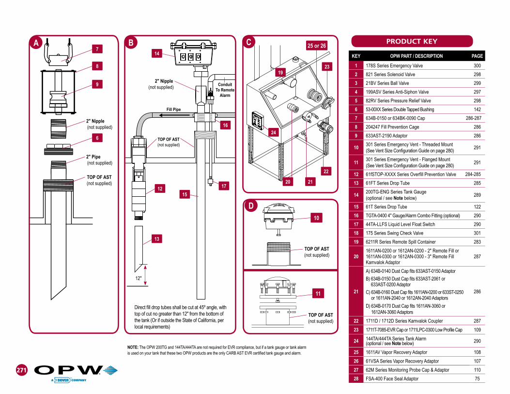
271
TOP OF AST(not supplied)
2" Nipple(not supplied)
Fill Pipe
271
KEY OPW PART / DESCRIPTION PAGE
1 178S Series Emergency Valve 300
2 821 Series Solenoid Valve 298
3 21BV Series Ball Valve 299
4 199ASV Series Anti-Siphon Valve 297
5 82RV Series Pressure Relief Valve 298
6 53-00XX Series Double Tapped Bushing 142
7 634B-0150 or 634BK-0090 Cap
8 204247 Fill Prevention Cage 286
9 633AST-2190 Adaptor 286
10301 Series Emergency Vent - Threaded Mount (See Vent Size Configuration Guide on page 280)
291
11301 Series Emergency Vent - Flanged Mount(See Vent Size Configuration Guide on page 280)
291
12 61fSTOP-XXXX Series Overfill Prevention Valve
13 61FT Series Drop Tube 285
14200TG-ENG Series Tank Gauge (optional / see Note below)
289
15 61T Series Drop Tube 122
16 TGTA-0400 4" Gauge/Alarm Combo Fitting (optional) 290
17 44TA-LLFS Liquid Level Float Switch 290
18 175 Series Swing Check Valve 301
19 6211R Series Remote Spill Container 283
201611AN-0200 or 1612AN-0200 - 2" Remote Fill or 1611AN-0300 or 1612AN-0300 - 3" Remote Fill Kamvalok Adaptor
287
21
A) 634B-0140 Dust Cap fits 633AST-0150 Adaptor
B) 634B-0150 Dust Cap fits 633AST-2061 or 633AST-0200 Adaptor
C) 634B-0160 Dust Cap fits 1611AN-0200 or 633ST-0250 or 1611AN-2040 or 1612AN-2040 Adaptors
D) 634B-0170 Dust Cap fits 1611AN-3060 or 1612AN-3060 Adaptors
286
22 1711D / 1712D Series Kamvalok Coupler 287
23 1711T-7085-EVR Cap or 1711LPC-0300 Low Profile Cap 109
24 144TA/444TA Series Tank Alarm(optional / see Note below) 290
25 1611AV Vapor Recovery Adaptor 108
26 61VSA Series Vapor Recovery Adaptor 107
27 62M Series Monitoring Probe Cap & Adaptor 110
28 FSA-400 Face Seal Adaptor 75
7
8
9
A C
2" Nipple(not supplied)
2" Pipe(not supplied)
TOP OF AST(not supplied)
6
16
17
24
20 21
22
1923
15
14
13
12
B PRODUCT KEY
Direct fill drop tubes shall be cut at 45º angle, with top of cut no greater than 12" from the bottom of the tank (Or if outside the State of California, per local requirements)
D
TOP OF AST(not supplied)
TOP OF AST(not supplied)
10
11
12"
Conduit To Remote
Alarm
25 or 26
NOTE: The OPW 200TG and 144TA/444TA are not required for EVR compliance, but if a tank gauge or tank alarm is used on your tank that these two OPW products are the only CARB AST EVR certified tank gauge and alarm.
284-285
286-287
272
To P
ress
ure
Vacu
um V
ent
272272
A
B
28
3
1
D
4 19 30
21
32
C
31
31
3 12
13
29
2
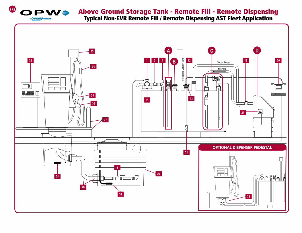
Vapor Return
Fill Pipe
Above Ground Storage Tank - Remote Fill - Remote Dispensing Typical Non-EVR Remote Fill / Remote Dispensing AST Fleet Application
33
34
36
38
35
OPTIONAL DISPENSER PEDESTAL31
37

273273
5
6
7
A
2" Nipple(not supplied)
2" Pipe(not supplied)
TOP OF AST(not supplied)
8
OPW PART / DESCRIPTION PAGE
1 821 Series Solenoid Valve 298
2 82RV Series Pressure Relief Valve 298
3 21BV Series Ball Valve 299
4 199ASV Series Anti-Siphon Valve 297
5 634B-0150 or 634BK-0090 Cap
6 204247 Fill Prevention Cage 286
7 633AST-2190 Adaptor 286
8 53-00XX Series Double Tapped Bushing 142
9 61T Series Drop Tube 122
10301 Series Emergency Vent - NPT Mount(See Vent Size Configuration Guide on page 280)
291
11301 Series Emergency Vent - Flanged Mount(See Vent Size Configuration Guide on page 280)
291
12 62M Series Monitoring Probe Cap & Adaptor 110
13 FSA-400 Face Seal Adaptor 75
14 61fSTOP-XXXX Series Overfill Prevention Valve
15 61FT Series Drop Tube 285
16 200TG-ENG Series Tank Gauge (optional / see Note below) 289
17 TGTA-0400 4" Gauge/Alarm Combo Fitting 290
18 44TA-LLFS Liquid Level Float Switch 290
19 175 Series Swing Check Valve 301
20 6211R Series Remote Spill Container 283
21 144TA/444TA Series Tank Alarm(optional / see Note below) 290
221611AN-0200 or 1612AN-0200 - 2" Remote Fill or 1611AN-0300 or 1612AN-0300 - 3" Remote Fill Kamvalok Adaptor
287
23
A) 634B-0140 Dust Cap fits 633AST-0150 Adaptor
B) 634B-0150 Dust Cap fits 633AST-2061 or 633AST-0200 Adaptor
C) 634B-0160 Dust Cap fits 1611AN-0200 or 633ST-0250 or 1611AN-2040 or 1612AN-2040 Adaptors
D) 634B-0170 Dust Cap fits 1611AN-3060 or 1612AN-3060 Adaptors
286
24 1711D / 1712D Series Kamvalok Coupler 287
25 1711T-7085-EVR Cap or 1711LPC-0300 Low Profile Cap 109
26 1611AV Vapor Recovery Adaptor 108
27 61VSA Series Vapor Recovery Adaptor 107
28Flexible Piping Systems for Fuel Oil & Generator Applications
29 Underground Containment Systems 52
PRODUCT KEY
D
C
Direct fill drop tubes shall be cut at 45º angle, with top of cut no greater than 12" from the bottom of the tank (Or if outside the State of California, per local requirements)
16
17
18
9
14
15
2520
21
22 23
24
B
TOP OF AST(not supplied)
10
11
TOP OF AST(not supplied)
Fill Pipe
TOP OF AST(not supplied)
30 Automatic Tank Monitoring & Leak Detection Equipment 314-328
31 Probes & Sensors for Liquid & Vapors 320-326
32 Automated Fuel Control System 332-342
12"
2" Nipple(not supplied) Conduit
To Remote Alarm
26 or 27
286-287
284-285
50-51
33 100 & 102 Series Hose Retractors
34 Breakaways
35 Fueling Nozzles
36 Swivels
37 Island Forms and Bumper Guards
38 Dispenser Pedestal 139
260-264
254-258
178-185
161-175 & 215
178-181 & 216-218
NOTE: The OPW 200TG and 144TA/444TA are not required for EVR compliance, but if a tank gauge or tank alarm is used on your tank that these two OPW products are the only CARB AST EVR certified tank gauge and alarm.

274 Above Ground Storage Tank - Remote Fill Typical Diesel/Fuel Oil/Generator Application
28
30
3
3
1
29
AA
BD
To P
ress
ure
Vacu
um V
ent
3
2
4 12
13
19Vapor Return
Fill Pipe
C
31
31

Direct fill drop tubes shall be cut at 45º angle, with top of cut no greater than 12" from the bottom of the tank (Or if outside the State of California, per local requirements)
275
5
6
7
A
2" Nipple(not supplied)
2" Pipe(not supplied)
TOP OF AST(not supplied)
8
PRODUCT KEYB
TOP OF AST(not supplied)
D
2" Nipple(not supplied)
Fill Pipe
ConduitTo Remote
Alarm
TOP OF AST(not supplied)
C16
17
18 9
14
15
10
26 or 27
2520
21
22 23
24
NOTE: The OPW 200TG and 144TA/444TA are not required for EVR compliance, but if a tank gauge or tank alarm is used on your tank that these two OPW products are the only CARB AST EVR certified tank gauge and alarm.
11
TOP OF AST(not supplied)
12"
OPW PART / DESCRIPTION PAGE
1 821 Series Solenoid Valve 298
2 82RV Series Pressure Relief Valve 298
3 21BV Series Ball Valve 299
4 199ASV Series Anti-Siphon Valve 297
5 634B-0150 or 634BK-0090 Cap
6 204247 Fill Prevention Cage 286
7 633AST-2190 Adaptor 286
8 53-00XX Series Double Tapped Bushing 142
9 61T Series Drop Tube 122
10301 Series Emergency Vent - NPT Mount(See Vent Size Configuration Guide on page 280)
291
11301 Series Emergency Vent - Flanged Mount(See Vent Size Configuration Guide on page 280)
291
12 62M Series Monitoring Probe Cap & Adaptor 110
13 FSA-400 Face Seal Adaptor 75
14 61fSTOP-XXXX Series Overfill Prevention Valve
15 61FT Series Drop Tube 285
16 200TG-ENG Series Tank Gauge (optional / see Note below) 289
17 TGTA-0400 4" Gauge/Alarm Combo Fitting 290
18 44TA-LLFS Liquid Level Float Switch 290
19 175 Series Swing Check Valve 301
20 6211R Series Remote Spill Container 283
21 144TA/444TA Series Tank Alarm(optional / see Note below) 287
221611AN-0200 or 1612AN-0200 - 2" Remote Fill or 1611AN-0300 or 1612AN-0300 - 3" Remote Fill Kamvalok Adaptor
287
23
A) 634B-0140 Dust Cap fits 633AST-0150 Adaptor B) 634B-0150 Dust Cap fits 633AST-2061 or
633AST-0200 AdaptorC) 634B-0160 Dust Cap fits 1611AN-0200 or 633ST-0250
or 1611AN-2040 or 1612AN-2040 AdaptorsD) 634B-0170 Dust Cap fits 1611AN-3060 or
1612AN-3060 Adaptors
286
24 1711D / 1712D Series Kamvalok Coupler 287
25 1711T-7085-EVR Cap or 1711LPC-0300 Low Profile Cap 109
26 1611AV Vapor Recovery Adaptor 108
27 61VSA Series Vapor Recovery Adaptor 100
28Flexible Piping Systems for Fuel Oil & Generator Applications
29 Underground Containment Systems 52
30 Automatic Tank Monitoring & Leak Detection Equipment 314-328
31 Probes & Sensors for Liquid & Vapors 320-326
286-287
284-285
50-51
276
DC
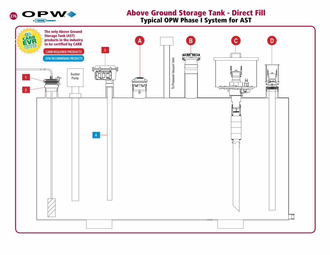
276 Above Ground Storage Tank - Direct Fill Typical OPW Phase I System for AST
3
1
2
4
Suction Pump
A B
To P
ress
ure
Vacu
um V
entOPW RECOMMENDED PRODUCTS
CARB REQUIRED PRODUCTS
The only Above Ground Storage Tank (AST) products in the industry to be certified by CARB

277277
TOP OF AST(not supplied)
1DK-2100EVR Drain Valve
17
18
19
11
12
13
15
16
14 with 1DK-2100EVR
Drain Valve
Direct fill drop tubes shall be cut at 45º angle, with top of cut no greater than 6" from the bottom of the tank (Or if outside the State of California, per local requirements)
C D
2" Nipple(not supplied)
2" Pipe(not supplied)
TOP OF AST(not supplied)
20
4" Nipple (not supplied)
2" Nipple (supplied)
OPW PART / DESCRIPTION PAGE
1 62M Series Monitoring Probe Cap & Adaptor 110
2 FSA-400 Face Seal Adaptor 75
3 200TG-ENG Series Tank Gauge (optional / see Note below) 289
4 61T Series Drop Tube 122
5301 Series Emergency Vent - NPT Mount(See Vent Size Configuration Guide on page 280)
291
6301 Series Emergency Vent - Flanged Mount(See Vent Size Configuration Guide on page 280)
291
7 1711T-7085-EVR Cap 109
8 1611AV Vapor Recovery Adaptor 108
9 1711LPC-0300 Low Profile Cap 109
10 61VSA Series Vapor Recovery Adaptor 107
11 1711D / 1712D Series Kamvalok Coupler 287
12
A) 634B-0140 Dust Cap fits 633AST-0150 Adaptor
B) 634B-0150 Dust Cap fits 633AST-2061 or 633AST-0200 Adaptor
C) 634B-0160 Dust Cap fits 1611AN-0200 or 633ST-0250 or 1611AN-2040 or 1612AN-2040 Adaptors
D) 634B-0170 Dust Cap fits 1611AN-3060 or 1612AN-3060 Adaptors
286
131611AN-2040 or 1612AN-2040 - 2" Direct Fill or 1611AN-3060 or 1612AN-3060 - 3" Direct Fill Kamvalok Adaptor
287
14 331 or 332 Series Spill Container 282
15 61fSTOP-XXXXT Series Overfill Prevention Valve 284
16 61FT Drop Tube 285
17 634B-0150 or 634BK-0090 Cap
18 204247 Fill Prevention Cage 286
19 633AST-2190 Adaptor 286
20 53-00XX Series Double Tapped Bushing 142
A
6
TOP OF AST(not supplied)
NOTE: The OPW 200TG and 144TA/444TA are not required for EVR compliance, but if a tank gauge or tank alarm is used on your tank that these two OPW products are the only CARB AST EVR certified tank gauge and alarm.
OPW RECOMMENDED PRODUCTSCARB REQUIRED PRODUCTS
The only Above Ground Storage Tank (AST) products in the industry to be certified by CARB5
TOP OF AST(not supplied)
6"
7
8 10
9
TOP OF AST(not supplied)
B
OR
Any Comination
286-287

278 Above Ground Storage Tank - Remote Fill - Remote Dispensing Typical OPW Phase I System for AST
27
26
To P
ress
ure
Vacu
um V
ent
AB
D
C
OPW RECOMMENDED PRODUCTS
CARB REQUIRED PRODUCTS
The only Above Ground Storage Tank (AST) products in the industry to be certified by CARB
5
18
3 42
1
Fill Pipe
Vapor Return
28
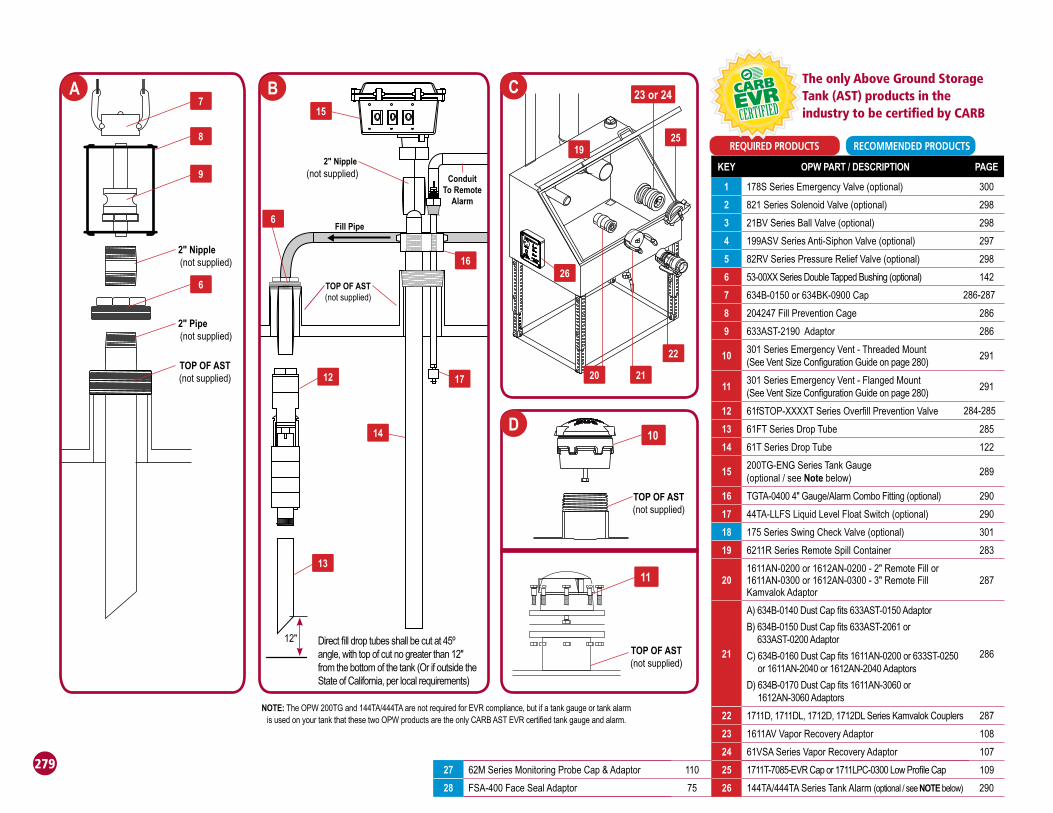
27 62M Series Monitoring Probe Cap & Adaptor 110
28 FSA-400 Face Seal Adaptor 75
279
7
8
9
A C
2" Nipple(not supplied)
2" Pipe(not supplied)
TOP OF AST(not supplied)
6
1626
20 21
22
1925
14
15
13
12
6
B
D
Direct fill drop tubes shall be cut at 45º angle, with top of cut no greater than 12" from the bottom of the tank (Or if outside the State of California, per local requirements)
KEY OPW PART / DESCRIPTION PAGE
1 178S Series Emergency Valve (optional) 300
2 821 Series Solenoid Valve (optional) 298
3 21BV Series Ball Valve (optional) 298
4 199ASV Series Anti-Siphon Valve (optional) 297
5 82RV Series Pressure Relief Valve (optional) 298
6 53-00XX Series Double Tapped Bushing (optional) 142
7 634B-0150 or 634BK-0900 Cap
8 204247 Fill Prevention Cage 286
9 633AST-2190 Adaptor 286
10301 Series Emergency Vent - Threaded Mount (See Vent Size Configuration Guide on page 280)
291
11301 Series Emergency Vent - Flanged Mount(See Vent Size Configuration Guide on page 280)
291
12 61fSTOP-XXXXT Series Overfill Prevention Valve
13 61FT Series Drop Tube 285
14 61T Series Drop Tube 122
15200TG-ENG Series Tank Gauge (optional / see Note below)
289
16 TGTA-0400 4" Gauge/Alarm Combo Fitting (optional) 290
17 44TA-LLFS Liquid Level Float Switch (optional) 290
18 175 Series Swing Check Valve (optional) 301
19 6211R Series Remote Spill Container 283
201611AN-0200 or 1612AN-0200 - 2" Remote Fill or 1611AN-0300 or 1612AN-0300 - 3" Remote Fill Kamvalok Adaptor
287
21
A) 634B-0140 Dust Cap fits 633AST-0150 Adaptor
B) 634B-0150 Dust Cap fits 633AST-2061 or 633AST-0200 Adaptor
C) 634B-0160 Dust Cap fits 1611AN-0200 or 633ST-0250 or 1611AN-2040 or 1612AN-2040 Adaptors
D) 634B-0170 Dust Cap fits 1611AN-3060 or 1612AN-3060 Adaptors
286
22 1711D, 1711DL, 1712D, 1712DL Series Kamvalok Couplers 287
23 1611AV Vapor Recovery Adaptor 108
24 61VSA Series Vapor Recovery Adaptor 107
25 1711T-7085-EVR Cap or 1711LPC-0300 Low Profile Cap 109
26 144TA/444TA Series Tank Alarm (optional / see NOTE below) 290
NOTE: The OPW 200TG and 144TA/444TA are not required for EVR compliance, but if a tank gauge or tank alarm is used on your tank that these two OPW products are the only CARB AST EVR certified tank gauge and alarm.
RECOMMENDED PRODUCTSREQUIRED PRODUCTS
The only Above Ground Storage Tank (AST) products in the industry to be certified by CARB
TOP OF AST(not supplied)
10
TOP OF AST(not supplied)
11
TOP OF AST(not supplied)
17
Fill Pipe
12"
2" Nipple(not supplied) Conduit
To RemoteAlarm
23 or 24
286-287
284-285
280
AB
OVE
GR
OU
ND
STO
RA
GE
TAN
K
EMER
GEN
CY
VEN
T G
UID
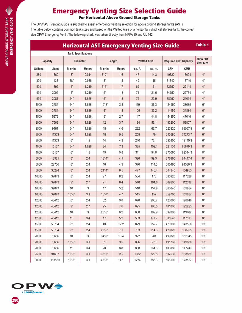
EEmergency Venting Size Selection Guide
For Horizontal Above Ground Storage Tanks
The OPW AST Venting Guide is supplied to assist emergency venting selection for above ground storage tanks (AST).
The table below contains common tank sizes and based on the Wetted Area of a horizontal cylindrical storage tank, the correct
size OPW Emergency Vent . The following chart, was taken directly from NPFA 30 and UL 142.
Horizontal AST Emergency Venting Size GuideTank Specifications
Capacity Diameter Length Wetted Area Required Vent CapacityOPW 301 Vent Size
Gallons Liters ft. or in. Meters ft. or in. Meters sq. ft. sq. m. CFH CMH
280 1560 3' 0.914 5'-2" 1.6 47 14.3 49520 15094 4"
300 1135 38" 0.965 5' 1.5 49 15 51640 15740 4"
500 1892 4' 1.219 5'-5" 1.7 69 21 72650 22144 4"
530 2006 4' 1.219 6' 1.8 71 21.6 74750 22784 4"
550 2081 64" 1.626 6' 1.8 75 22.9 78950 24064 4"
1000 3784 64" 1.626 10'-8" 3.3 119 36.3 124950 38085 6"
1000 3784 64" 1.626 6' 1.8 109 33.2 114450 34884 6"
1500 5676 64" 1.626 9' 2.7 147 44.8 154350 47046 6"
2000 7569 64" 1.626 12' 3.7 184 56.1 193200 58807 6"
2500 9461 64" 1.626 15' 4.6 222 67.7 223320 68067.9 6"
3000 11353 64" 1.626 18' 5.5 259 79 243680 74273.7 6"
3000 11353 6' 1.8 14' 4.3 240 73.1 233400 12140.3 6"
4000 15137 64" 1.626 24' 7.3 335 102.1 281100 85679.3 8"
4000 15137 6' 1.8 19' 5.8 311 94.8 270060 82314.3 8"
5000 18921 8' 2.4 13'-4" 4.1 326 99.3 276960 84417.4 8"
6000 22706 8' 2.4 16' 4.9 376 114.6 300480 91586.3 8"
8000 30274 8' 2.4 21'-4" 6.5 477 145.4 344340 104955 8"
10000 37843 8' 2.4 27' 8.2 584 178 385920 117628 8"
10000 37843 9' 2.7 21' 6.4 540 164.6 369200 112532 8"
10000 37843 10' 3 17' 5.2 518 157.9 360840 109984 8"
10000 37843 10'-6" 3.1 15'-7" 4.7 515 157 359700 109637 8"
12000 45412 8' 2.4 32' 9.8 678 206.7 420080 128040 8"
12000 45412 9' 2.7 25' 7.6 625 190.5 401000 122225 8"
12000 45412 10' 3 20'-6" 6.2 600 182.9 392000 119482 8"
12000 45412 11' 3.4 17' 5.2 583 177.7 385540 117513 8"
15000 56764 8' 2.4 40' 12.2 829 252.7 470990 143558 10"
15000 56764 8' 2.4 23'-5" 7.1 703 214.3 429020 130765 10"
20000 75686 10' 3 34'-2" 10.4 922 281 499820 152345 10"
20000 75686 10'-6" 3.1 31' 9.5 896 273 491760 149888 10"
20000 75686 11' 3.4 28' 8.8 868 264.6 483080 147243 10"
25000 94607 10'-6" 3.1 38'-6" 11.7 1082 329.8 537530 163839 10"
30000 113529 10'-6" 3.1 46'-3" 14.1 1274 388.3 568100 173157 10"
Table 1

281
AB
OVE
GR
OU
ND
STO
RA
GE
TAN
K
EMER
GEN
CY
VEN
T G
UID
E
Horizontal AST Emergency Vent Selection For Horizontal Above Ground Storage Tanks
TABLE 1 is a pre-calculated chart that may have all the information needed to choose the proper emergency vent. If the tank size is not in the pre-calculated chart, use the example below as a guide to figure out the wetted area, cubic feet per hour (CFH), and proper vent selection for the particular tank.
**EXAMPLE:
Given: Tank capacity is 10,000 gallons; 10 feet in diameter x 17 feet long.
Step 1
From TABLE 1: WA = 518 sq. ft.
If not in the table, do the following to calculate the wetted area:
Formula: WA=.75 2 + pdl =.75 + pdl
WA = wetted area in square feet75% = horizontal tank factorp = 3.14d = diameter of tank end in feetl = length of tank in feet
WA=.75 + (3.14 x 10 x 17) WA=.75(157.0 + 533.8) = 518 square feet rounded
Step 2
If the tank size is in the chart, use the supplied CFH values to determine the emergency vent size needed in TABLE 1.
If not in the charts, continue the following example:
Using 518 square feet, the cubic feet per hour (CFH) can be found using TABLE 1. Since 518 falls between the values of 500 and 600, interpolation is necessary as follows:
600 sq. ft. 392,000 CFH -500 sq. ft. -354,000 CFH Difference: 100 sq. ft. 38,000 CFH
38,000 x
100 518-500 Total CFH required = 354,000 CFH + 6,840 CFH = 360,840 CFH
Step 3
Vent selection: using TABLE 1, find the range in which 360,840 CFH falls. The tables show that an 8" emergency vent is needed.
**PEI Recommended Practices 200-96
; x =6,840 CFH
3.4 x10²
2
pd 2
4pd 2
2

DimensionsCapacity A B
Model # gal. liter in. cm in. cm
331 7 26.5 15 38 17 43
332 7 26.5 14 35 17 43
282
POM
ECO
/OPW
331
AST
& 33
2AST
DIR
ECT-
FILL
AB
OVE
GRO
UND
STO
RAG
E TA
NK S
PILL
CO
NTAI
NERS
uEasy Installation – 4" and 6" NPT threaded base screws directly to the tank riser pipe. No further adjustments are needed.
uIntegral Drain Valve – allows high-speed drainage of spilled product back into the tank.
uCapacity – available in 7-gallon (26.5 liter) container capacity. Larger 7-gallon capacity spill containers provide additional clearance for 61ƒSTOP Overfi ll Prevention Valves (3.5 gallon-221 only).
uRain-Shedding Cover Design – hooded cover design helps prevent water or snow entry by extending thelip of the cover over the body of thespill container.
uWelded-Hinge, Lockable Hatch – the cover includes a provision for a padlock and a welded-hinge assembly for added security.
u12 Gauge Epoxy-Powder Coated Construction – heavy-duty materials, compatible with hydrocarbons, for long service life and added security.
u331AST Heavyweight, Welded Base Design – all versions have cast-iron base and 12-gauge steel walls (model 331) and 14-gauge steel wall (model 332) provide solid strength for heavy-duty applications.
u332AST Spun Steel Design – spun steel construction provides a lightweight, one-piece design for easy installation and a clean, sleek appearance onaboveground tanks.
uAll Models Are ULC Listed – clearly labeled to identify the listing.
uCARB EVR Certifi ed
POMECO/OPW 331AST & 332AST Direct-Fill Above Ground Storage Tank Spill Containers
POMECO/OPW Direct-Fill AST Spill
Containers are designed to prevent
spilled product from entering soil near
the fi ll and vapor return riser connections
on an above ground storage tank during
normal tank fi lling operation. The spill
containers catch spillage to help prevent
soil contamination and groundwater
pollution. POMECO/OPW Direct-Fill AST
Spill Containers thread on the top of an
above ground tank and allow for drainage
of spilled product back into the tank.
Features
331AST
331AST and 332AST Spill Containers Instruction Sheet Order Number: 203168
CARB APPROVED AST EQUIPMENT
Product No. Description Liters
331-ASTW74 Welded, 7 gallon, 4" NPT Welded, 26.4 liter, 4" NPT
331-ASTW76 Welded, 7 gallon, 6" NPT Welded, 26.4 liter, 6" NPT
332-ASTW74 Spun, 7 gallon, 4" NPT Spun, 26.4 liter, 4" NPT
332-ASTW76 Spun, 7 gallon, 6" NPT Spun, 26.4 liter, 6" NPT
Ordering Specifi cations:
Listings and Certifi cations
CARB Certifi edAST Phase 1 Enhanced Vapor Recovery (EVR) SystemEO-VR 401-B
B
A
331-AST
B
A
332-AST
283
POM
ECO
/OPW
211
-RM
OT
L – Adjustable legs and No base drain valve
LD – Adjustable legs with base drain valve
N – No legs and No base drain valveND – No legs with base
drain valve
6 R – 211 15 0 B2 L 211SS 20 1 B3 LD 30 2 B4 N N ND
0 – No entry holes1 – 1, 4" entry hole2 – 2, 4" entry holes
(30 Gallon Only)
211 – 12 Gauge Powder-
Coated Steel Construction
211SS – Stainless Steel Construction
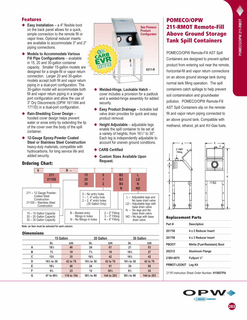
POMECO/OPW 211-RMOT Remote-Fill Above Ground Storage Tank Spill Containers
POMECO/OPW Remote-Fill AST Spill
Containers are designed to prevent spilled
product from entering soil near the remote,
horizontal-fill and vapor return connections
on an above ground storage tank during
normal tank filling operation. The spill
containers catch spillage to help prevent
soil contamination and groundwater
pollution. POMECO/OPW Remote-Fill
AST Spill Containers slip on the remote-
fill and vapor return piping connected to
an above ground tank. Compatible with
methanol, ethanol, jet and AV-Gas fuels.
D
C
B
A
2" FNPTFitting
FE
G
Featuresu Easy Installation – a 4" flexible boot
on the back panel allows for a quick, simple connection to the remote fill or vapor lines. Optional reducer inserts are available to accommodate 3" and 2" piping connections.
u Models to Accommodate Various Fill Pipe Configurations – available in 15, 20 and 30-gallon container capacity. Smaller 15-gallon models are designed for a single-fill or vapor return connection. Larger 20 and 30-gallon models accept both fill and vapor return piping in a dual-port configuration. The 30-gallon model will accommodate both fill and vapor return piping in a single-port configuration and allow the use of 3" Dry Disconnects (OPW 1611AN and 1711D) in a dual-port configuration.
u Rain-Shedding Cover Design – hooded cover design helps prevent water or snow entry by extending the lip of the cover over the body of the spill container.
u 12-Gauge Epoxy-Powder Coated Steel or Stainless Steel Construction heavy-duty materials, compatible with hydrocarbons, for long service life and added security.
u Welded-Hinge, Lockable Hatch – cover includes a provision for a padlock and a welded-hinge assembly for added security.
u Easy Product Drainage – lockable ball valve drain provides for quick and easy product removal.
u Height Adjustable – adjustable legs enable the spill container to be set at a variety of heights, from 161/2" to 30". Each leg is independently adjustable to account for uneven ground conditions.
uCARB Certified
u Custom Sizes Available Upon Request.
Dimensions15 Gallon 20 Gallon 30 Gallon
in. cm in. cm in. cmA 181/4 46 24 61 21 53
B 73⁄8 19 71/2 19 101/2 27
C 135⁄8 35 161/2 42 161/2 42
D 161/2 to 30 42 to 76 161/2 to 30 42 to 76 161/2 to 30 42 to 76E 181/4 46 24 61 34 86F 91/8 23 12 301/2 91/2 24
G 47 to 601/2 119 to 154 561/2 to 80 144 to 203 561/2 to 80 144 to 203
Replacement Parts
Part # Description
201758 4 x 2 Reducer Insert
201759 4 x 3 Reducer Insert
PBOOT Nitrile (Fuel-Resistant) Boot
202312 Aluminum Flange
21BV-0075 Fullport 3/4"
PRMOT-LEGKIT Leg Kit
Ordering Chart:
6211-R
15 – 15 Gallon Capacity 20 – 20 Gallon Capacity 30 – 30 Gallon Capacity
2 – 2" Fitting 3 – 3" Fitting 4 – 4" Fitting
B – Booted entry fittings in holes
N – No fittings in holes
Note: an item must be selected for each column.
See Pomeco Product Configurator
211R Instruction Sheet Order Number: H15857PA

284
OPW
OVE
RFI
LL P
REV
ENTI
ON
VA
LVES OPW 61ƒSTOP
“THE STOPPER” Overfi ll Prevention Valves
The OPW 61ƒSTOP Overfi ll Prevention
Valve (“The Stopper”) is designed to prevent
overfi lling of above ground storage tanks
by providing a positive shut-off during a
pressurized-fill (pump-on fill) delivery.
“The Stopper” threads into the fi ll opening
and is an integral part of the fill tube.
The OPW61ƒSTOP is fully adjustable to
allow for easy installation in new or existing
above ground tanks of various heights and
storage capacities.
The Stopper is a single-action, complete
shut-off valve. When the liquid level rises to
your specifi c, pre-determined tank capacity,
the valve mechanism is released and
automatically closes with the flow of the
product. Any excess product left between
the valve and the fuel delivery coupler is
drained into the tank through internal drain
vents. The drain vents on the 61fSTOP act as
an anti-siphon, by introducing air/vapor into the
fi ll line, to help isolate the tank from a potential
siphon due to a broken or leaking fi ll pipe.
The 61ƒSTOP, available in either 2" or 3"
full-fl ow models, maximizes fl ow rates and
minimizes delivery times. The 2" 61ƒSTOP
requires a 4" tank opening and minimum tank
ullage (space from the top of the stored product
to the inside top of the tank) of 8" on the
61ƒSTOP-1000 Cylindrical Float model and
a minimum ullage of 4" on the 61ƒSTOP-
2000 Float Arm model. The 61ƒSTOP-1000,
with the cylindrical fl oat, eliminates the need
to position the valve to avoid tank walls or
cross-bracing. The 61ƒSTOP-2000 with the
fl oat arm allows for increased usable storage
capacity in the tank, and is well-suited for
small capacity rectangular ASTs. The 3"
61ƒSTOP requires a 6" tank opening and
incorporates a cylindrical fl oat requiring 8"
of tank ullage space.
61ƒStop-1000 61ƒStop-3050
u A Special Crossbar Tank-Inlet Adaptor –is provided with each Stopper to provide for tight-fi lls and help prohibit open-fi lls. Mounting hardware, upper drop tube and 14" lower drop tube provided (longer-length drop tubes can be purchased or added).
u Completely Automatic Operation – no pre-checks to perform, no resets, and no overrides to be broken or abused.
u Direct or Remote-Fill Compatible – fuel delivery couplers can be connected directly to the 61ƒSTOP, or steel pipe can be threaded into the top of the valve and piped to a remote location where the couplers are contained in a 211-RMOT Spill Container.
u Integral Anti-Siphon Valve – drain vents on the 61ƒSTOP act as an anti-siphon, by introducing air/vapor into the fi ll line after the valve actuates, to help isolate the tank from a potential siphon due toa broken or leaking remote-fi ll pipe.
u 150 psi (10 bar) Pressure Rated* with Low Pressure Drop – to enable quick, safe delivery of fuel into the tank.
u 25 GPM (95 lpm) Minimum Flow Rate Required.
u UL and ULC Listed – to satisfyThird Party accreditationrequirements of many jurisdictions.
u CARB Approved VR-401-A; VR-401-B
Features
Valve Body, Adaptor and Collar: cast aluminum
Poppet: Cast aluminum, hard-coated
Cam: Stainless steel
Follower: brass
Shaft: CRS zinc-plated
Bearing: Sintered bronze
Float: Closed-cell nitrile
Nipple: 2" - 3" schedule 40 steel pipe
Lower Nipple: 2" - 3" schedule 40 steel pipe with Duragard® coating
Materials
* OPW does not recommend pumping pressures above 100 psi for Class 1B fuels or remote applications and we make no warranties for products use in conjunction with the 61ƒSTOP.
NOTE: OPW recommends the use of the 61ƒSTOP with clean product only. Debris and other products such as contaminated waste oil may cause improper operation of the valve.
NOTE: The 61ƒStop can be used in gravity drop provided the minimum fl ow rate is maintained. A tight shut-off is not achieved in the closed position. However with a minimum tank size of 1,000 gallons, the leak rate will provide a 30- minute warning before the tank is full.
CARB EVR Certifi edVR-401-A; VR-401-B
Approvals and Listings
61ƒStop-2000T 61ƒStop-3050T61ƒStop-1000T
61ƒStop-2000

285
Ordering Specifi cations and DimensionsA B C D E F
Product # Description in. cm in. cm in. cm in. cm in. cm in. cm
61fSTOP-1000 2" Cyl. Float 3 7.6 10 25.4 2 5.1 9 22.4 315⁄16 10 n/a n/a
61fSTOP-2000 2" Float Arm 3 7.6 10 25.4 1/2 3.8 5-18 22.4 131⁄32 5 6 15.2
61fSTOP-3050 3" Cyl. Float 3 7.6 105/8 27 2 5.1 8 20.3 51/8 13 n/a n/a
Replacement Parts 3"
Product # Description
D02037M 6" Retaining Collar
C04474RS 14" Nipple
Replacement Parts 2"
Product # Description
C04093M 4" Retaining Collar
C04114RS 14" Nipple
OPW
61ƒ
STO
P O
VER
FILL
PR
EVEN
TIO
N V
ALV
ES
61ƒStop-1000
2" Schedule 40 Pipe Nipple
4" NPTInternal
2" Schedule 40 Pipe Nipple
ED
B
A
C
61ƒStop-1000T
2" Schedule 40 Pipe Nipple
D
B
A
C
A
BF
C D
E
61ƒStop-2000
A
B
E
C
D
61ƒStop-2000T
B
C
3" Schedule 40Pipe Nipple
6" NPT Internal Threads
E
3" Schedule 40Pipe Nipple
D
271/2"
A
61ƒStop-3050
B
C
3" Schedule 40 Pipe Nipple
D
271/2"
A
61ƒStop-3050T
61ƒStop-2"PR
ESSU
RE
DR
OP
- PSI
FLOW RATE - GPM
61ƒStop-3"
PRES
SUR
E D
RO
P - P
SI
FLOW RATE - GPM
Replacement Parts 3"
Product # Description
C04438M Float (4 pieces required for 3050)
OPW 61FT Drop TubeThe OPW 61FT Drop Tube is designed to install on the bottom of the 61ƒSTOP AST Overfi ll Prevention Valves when a lightweight, longer, lower drop tube is required. Constructed of extruded aluminum, the OPW 61FT is connected to the bottom of the 61ƒSTOP by a clevis and cotter pin assembly, and allows for submerged fi lling of ASTs.
Replacement Parts 2"
Product # Description
H12617M Float for 1000 (4 pieces required)
61ARM-2000 Floating Arm Retrofi t Kit For 2000
CARB APPROVED AST EQUIPMENT
Product # Description
61FT-0206 2" x 6' Drop Tube Kit
61FT-0312 3" x 12' Drop Tube Kit
Ordering Specifi cations and Dimensions
61FT Drop Tube Instruction Sheet Order Number: H14428PA
61FSTOP-1000, 100M, 200M Instruction Sheet Order Number: H12676M
61FSTOP-2000 Instruction Sheet Order Number: H13337M
61FSTOP-3000, 3050, 305A Instruction Sheet Order Number: H13315M
61FT-0312, 0206 Instruction Sheet Order Number: H14428PA
61FSTOP-1000T, 2000T, 3050T Instruction Sheet Order Number: 203163
CARB APPROVED AST EQUIPMENT
A B C D E
Product # Description in. cm in. cm in. cm in. cm in. cm
61FSTOP-1000T 2" NPT with cylindrical fl oat 10 25.4 2 5.1 9 22.4 315⁄16 10 n/a n/a
61FSTOP-2000T 2" NPT with fl oat arm 10 25.4 1/2 3.8 5-18 22.4 131⁄32 5 6 15.2
61FSTOP-3050T 3" NPT with cylindrical fl oat 105/8 27 2 5.1 8 20.3 51/8 13 n/a n/a
*Recommended for E85
NOTE: When ordering a CARB EVR Certifi ed OPW 61ƒ STOP, the Fill Adaptor
must be ordered separately.

286
OPW
FU
EL D
ELIV
ERY
CO
UPL
ERS
AN
D A
CC
ESSO
RIE
S
Typical AST Filling Application
Fuel Delivery Couplers And Accessories
Fuel Delivery Couplers and Accessories
are designed to connect fuel delivery
transport truck hoses or nozzles to the
fi ll pipe of an aboveground storage tank.
633B Coupler
Kamlok® Couplers
The 633BD has a Kamlok® Coupler on one end and external threads on the other end. This coupler should be threaded into an OPW 190 Nozzle and then coupled to the 61ƒSTOP for fi lling ASTs.
Ordering Specifi cationsElbow/Thread
Product # in. mm
633BD-1261 2 x 11/2 51 x 38
633B-0150 2 x 2 51 x 51
633AST Spout Adaptor
Ordering Specifi cationsElbow/Thread
Product # in. mm
633AST-2061 2 x 2 51 x 51
633AST-3061 3 x 3 77 x 77
Tank Inlet Spout Adaptors With Crossbar
The 633AST Series Adaptors, with a boss installed across the inlet, are designed to prohibit open-fi lls. Adaptors are supplied with the 61ƒSTOP to provide for tight-fi lls.
633AST Spout Adaptor
Tank Inlet Spout Adaptors
The 633AST is an adaptor that can be threaded onto a 297 Spout. The spout and adaptor assembly may then be attached to a 190 Nozzle equipped with a 633BD Kamlok® coupler for open fi lling of ASTs when a 61ƒSTOP is not installed.
Dust Caps
The 634B Dust Caps are installed on 633AST Adaptors when not in use. The 634B is designed to deter dust, debris and water from entering the tank.
DedicatedGauging Port
For use with 633AST-0XXXFemale NPT Kamlok Gauging Port.
Ordering Specifi cationsCARB APPROVED AST EQUIPMENT
Product # Description in. mm
634B-0140 For 633AST-0150 1-1/2 38
634B-0150 Caps 633AST-2061 or 633AST-0200 Adaptor 2 51
634B-0160Caps 1611AN-0200 or 633AST-0250 or
1611AN-2040 or 1612AN-2040 Adaptors2-1/2 64
634B-0170Caps 61ƒSTOP (633AST-3061) or 366AST-0300 or 1611AN-3060 or
1612AN-3060 Adaptors3 77
634B-01801611AN-0300 Kamvalok® Adaptor or
633AST-0400 Adaptor4 103
Ordering Specifi cationsCARB APPROVED AST EQUIPMENT
Product # Description
204247 Dedicated Gauging Port
OPW 190High-Flow
Nozzle
OPW 633BDKamlok Coupler
OPW 633AST Spout Adaptor
Pomeco 211AST
AST Spill Container
OPW 634B Dust Cap
(covers inletwhen not fi lling)
OPW 61fSTOPOverfi ll
PreventionValve
Typical AST Filling Application
OPW 190High-Flow
Nozzle
OPW 633BDKamlok Coupler
Pomeco 211ASTAST Spill Container
OPW 633AST Spout Adaptor
OPW 297 Aluminum Spout
For more information contact OPW Customer Service at 1-800-422-2525; International call 1-513-870-3315.
Ordering Specifi cationsCARB APPROVED AST EQUIPMENT
Elbow/Thread
Product # in. mm
633AST-0150 1.5 x 1.5 38 x 38
633AST-0200 2 x 2 51 x 51
633AST-0250 2.5 x 2.5 64 x 64
633AST-0300 3 x 3 76 x 76
633AST-0400 4 x 4 102 x 102
366FAST-XXXX, Male Thread Equivelent of Adaptors above
Dust Cap

287
OPW
FU
EL D
ELIV
ERY
CO
UPL
ERS
AN
D A
CC
ESSO
RIE
S
Dust Plug
Lockable Dust Plug
Lockable Dust Caps
The 634BK-0090 is a 2" lockable dust cap for the 61ƒSTOP. It will cap off any 2" 633AST Tank Inlet Spout Adaptor and offers the added feature of being lockable.
Ordering Specifi cationsCARB APPROVED AST EQUIPMENT
Product # Description in. mm
634BK-0090 Caps 633AST Adaptor 2 51
634BK-0100 Caps 633AST Adaptor 3 77
634BK-0200 Caps 633AST Adaptor 4 103
Spout Kits And Delivery Couplers And Accessories
Fuel Delivery Couplers and Accessories are designed to connect fuel delivery transport truck hoses or nozzles to the fi ll pipe of an aboveground storage tank.
Poppeted Kamvalok® Adaptors
The 1611AN Series Kamvalok® Adaptor is installed at the fi ll pipe and replaces the 633AST. The 1611AN contains an internal spring-loaded valve assembly that automatically closes to help prevent fuel spillage. The 1611AN mates with the 1711D Coupler to open the spring-loaded valve and proceed with a delivery 204016.
1611 & 1612 Series Kamvalok® Adaptors
Installed onto the 61ƒSTOP overfi ll prevention valve. Contains an internal spring loaded valve assembly that automatically closes to help prevent fuel spillage.
Ordering Specifi cationsCARB APPROVED AST EQUIPMENT
Product # Seal in. mm
1611AN-0200 Remote Fill with Buna Seal 2 51
1611AN-0300 Remote Fill with Buna Seal 3 77
1612AN-0150 Remote Fill with Viton® Seal 11/2 38
1612AN-0200 Remote Fill with Viton® Seal 2 51
1612AN-0300 Remote Fill with Viton® Seal 3 77
* Thread and Kamvalok® same size
Poppeted Kamvalok® Couplers
The 1711D Series Kamvalok® Couplers are installed on the fuel delivery transport truck hose and mate with the 1611AN Adaptors. The combination of the 1711D and 1611AN enable dry connection and dry disconnection of delivery fi ttings to help prevent accidental spillage of product.
Ordering Specifi cationsCARB APPROVED AST EQUIPMENT
Product # Seal in. mm
1711D-1075 Buna 2 51
1711D-1080 Buna 3 77
1712D-1085 Viton® 11/2 38
1712D-1090 Viton® 2 51
1712D-1095 Viton® 3 77
* Thread and Kamvalok® same size
Dust Plugs
The 634A Dust Plug is installed in the end of the 1711D, when not in use. The 634A is designed to help prevent dust, dirt and debris from damaging the internal components of the 1711D Kamvalok® Coupler.
Ordering Specifi cationsProduct # Description in. mm
634A-0160 Plugs 1711D or 1712D - 2" Kamvalok® Coupler 2 1/2 64
634A-0180 Plugs 1711D or 1712D - 3" Kamvalok® Coupler 4 103
Poppeted Kamvalok® Couplers
Poppeted Kamvalok® Couplersfor Remote Fill
Kamvalok® Adaptor for Direct Fill
Typical AST Filling Application
OPW 1611AN or 1612AN Kamvalok Adaptor
OPW 1711D or 1712D Kamvalok Coupler
OPW 211-RMOT Remote Fill
Spill Container
CARB APPROVED AST EQUIPMENTProduct # Seal in. mm
1611AN-2040 Direct Fill with Buna seal 2 51
1612AN-2040 Direct Fill with Viton seal 2 51
1611AN-3060 Direct Fill with Buna seal 3 77
1612AN-3060 Direct Fill with Viton seal 3 77
Ordering Specifi cations
1611AN Adaptor Instruction Sheet Order Number: 204016
1611AN Adaptor Instruction Sheet Order Number: 204016
H32116PA Coupler Instruction Sheet Order Number: 204016

288288
OPW
200
TG A
ST M
ECH
AN
ICA
LTA
NK
GA
UG
E

289
OPW
200
TG A
ST M
ECH
AN
ICA
LTA
NK
GA
UG
E
C
Listings and Certifications
OPW 200TG AST Mechanical Tank Gauge
The OPW 200TG Tank Gauge is designed for reading liquid levels in horizontal or vertical above ground storage tanks. The 200TG Tank Gauge provides an accurate numerical counter readout, eliminating the need for any on-site manual gauging.
u Vapor-Tight – allows for standard tank pressure testing and sealing up to 25-psig (1.72 bar).
u Angled Face – improves visibility from ground on large diameter tanks. May be read easily up to 30 feet away (9.14 m).
u Swivel Adaptor Base – allows for 360° of rotation of gauge face for easy viewing wherever needed.
u Easy Installation – 2" NPT-threaded base reduces labor time, and comes standard with female thread. A H11421RS may be purchased for male threaded applications.
u Corrosion-Resistant Construction – powder-coated die cast-aluminum body assures for long service life in many fluids.
u Drop Tube – prevents float entanglement in the tank, and gives the gauge a more accurate reading when turbulence is present (Drop Tubes sold separately. They are recommended for use in tanks with high turbulence, and where other piping and structures inside the tank may cause entanglement).
u Float Buoyancy – designed to float in all approved fuels with a specific gravity of 0.65 and greater.
u Tank Height – unit designed for use on any horizontal or vertical aboveground tank up to 18 feet (5.5 m) in depth. Specials available upon request.
u Numbering – black letters on white background for ultimate contrast and better visibility. Characters stand over 1" (25 mm) tall.
u Unit Measurement – Can be purchased in metric units to read in meters, 1/10, 1/100, or in English units to read in feet and inches.
u Maintenance – No annual maintenance required.
u U.S. Patent No.: 6,523,404 - Other patents pending.
u Compatible Fuels– see chart on page 303.
uTemperature Rating – 120°F to -40°F (49°C to -40°C)
Underwriters Laboratory Listed UL Listing MH29367. Liquid level gauges which are intended to be used on above ground storage tanks and monitor the level of petroleum-based flammable or combustible fluids.
A
B
E
D
Features
Materials
Enclosure: Powder-coated aluminum
Swivel Base: Hard-coat aluminum
Float: 304 stainless steel
Lenses: Tempered borosilicate
Gears: Acetal
Gaskets & O-Rings: Nitrile®
All Hardware: Stainless steel
Accuracy: + or - 2"
Dimensions:in. cm
A 8 1/4 21
B 10 1/4 26
C 9 22.75
D 6 3/4 17.25
E 11/2 3.75
Replacement Parts:Part # Description
C05165M Float
H14358M Lens
H14909M Lid Gasket
Ordering Specifications:Product # Description lb. kg
200TG-ENG English Unit Tank Gauge up to 18 ft. 7.75 3.52
200TG-ENG40 English Unit Tank Gauge - 40 ft. 7.75 3.52
200TG-MET Metric Unit Tank Gauge up to 6 m 7.75 3.52
200TG-MET40 Metric Unit Tank Gauge - 10 m 7.75 3.52
(Ancillary Equipment)Product # Description lb. kg
H11421RS 2" NPT Male x Male Nipple 1.5 0.68
CARB CERTIFIED AST EQUIPMENT
61T-0208 2" Dia. x 8' Long Drop Tube 2.67 1.21
61T-0212 2" Dia. x 12' Long Drop Tube 4.00 1.81
61T-0216 2" Dia. x 16' Long Drop Tube 5.33 2.42
200TG
200TG Tank Gauge Instruction Sheet Order Number: H14912PA

290
Ordering Specifications:Product # Description lb. kg
444TA-0100* Four Signal Tank Alarm, does not include Float Switch 4 1.8
44TA-LLFS* 36" Liquid-Level Float Switch Sub-Assembly 0 0.0
144TA-0100Single Channel Liquid Level Tank Alarm, does not include Float Switch
4 1.8
TGTA-04004" Tank Bung Gauge and Alarm Combo Fitting (OPW 61T required for use)
10 4.5
The OPW 144TA Requires the OPW 44TA-LLFS, the OPW 44TA-LLFS must be purchased as a separate item.
OPW
444
TA A
ST
FOU
R S
IGN
AL
TAN
K A
LAR
M
144TA Dimensions:in. cm
A 5 1⁄32 12.8B 51⁄32 12.8C 3 7.6D 43⁄16 10.6E 115⁄16 4.9F 35 88.9G 115⁄16 4.9H 1 2.5
u Up to four alarm signals (444TA) – can be used for high or low liquid level sensing, interstitial monitoring, and/or other signals in one to 4 separate tanks.
uSelf-Powered – lithium battery with a 10-year shelf life for long service life.
u Audible Alarm – sounds a 90-decibel alarm at 4 feet away.
uVisual Notifications – red alarm light will flash during use for notification to the user. Low battery light indicates when battery needs replaced.
uCorrosion-Resistant Construction – petroleum and environmental resistant housing and all stainless steel pipe fitting ensure a long product life.
uProduct /Alarm Identification Label – located on top of the alarm for quick and easy identification, allowing you to correspond alarms to signals. Label
has a protective covering.
u Intrinsically Safe – complies with ANSI/UL 913 for Class 1, Division 1 & 2 for Groups C & D hazardous locations.
u Cold Weather Resistant – all components are safe for temperatures down to -40ºF operation (and up to 120º F).
uLong Life Lithium Battery – self-powered by a lithium battery which includes a 10-year shelf life to ensure peace of mind for the owner.
u Easy Installation – requires no calibration and installs easily into a 1" tank bung. May be assembled remotely or directly on top of tank.
Features
Materials
Enclosure: Polybutylene terephthalate
Wire Grommet: Nylon w/ buna seal
Float Switch: Closed cell buna float & stainless steel rod
Pipe: Stainless steel
Tank Adaptor: Aluminum hardcoat anodized
Conforms to ANSI / UL STD 913Certified to CAN / CSA STD C22.2 No. 157-92Florida EQ-610CARB Certified
444TA Dimensions:in. cm
A 5 1/32 12.8B 5 1/32 12.8C 43/16 10.6
Replacement Parts:Part # Description44TA-LLFS Liquid-Level Float Switch ASSY H15412M Wire Fitting H15411M Float Switch Items to Convert to a Low Level Alarm:202430 1/8" SST NippleC05295M SST TubeBattery Module H15937M 444TA-0100See Note 144TA-0100*
444TA
Approvals and Listings
TGTA-0400 4" Tank Bung Combo FittingNote: Drop Tube must be used with TGTA-0400.
3069027
444TA and 144TA Instruction Sheet Order Number: 200655
*NOTE: When replacing the battery for the 144TA-0100, open the alarm box and locate the OPW number on the black battery module. If the number reads “C05346” then use the replacement part 15615M. If the number reads “144TA-0100” then use the replacement part 202891.
OPW 444TA AST Four Signal Tank Alarm and OPW 144TA AST Liquid Level Tank AlarmThe OPW AST remote Four Signal Tank Alarm is designed to sense up to four different liquid levels or other signals using just one device.
The OPW 144TA Tank Alarm is designed for liquid level sensing.
Alarm Technical Information:Hazardous Location Approval: Class I, Groups C & DMaximum Voltage: 7.2 VoltsMaximum Current: 8 ma. per input (32 ma. total)Maximum Internal Capacitance: 23 uFMaximum Internal Inductance: 33 mHMaximum Ambient Temperature Rating: 60° CMaximum Surface Temperature Classification:T4 Surface CodeWiring limitations: 1000 foot maximum between the 144TA/444TA unit and any remote switch for each channel of the alarm. This assumes that maximum capacitance for any input is 60 nanoFarads and that the maximum inductance is 0.2 milliHenry per input (UL-913 A7.3)Note: This device is designed to work independently and should not be wired in parallel with another device, except as defined in the following instructions. Requirements for devices wired to the 144TA/444TA:• Attached wiring and devices must be classed
Intrinsically Safe
• No voltage or current source
• Maximum capacitance: 60 nanoFarads (.06 uF) per input
• Maximum inductance: 200 microHenrys (.2 mH) per input
Float Switch Technical Information: Minimum liquid specific gravity: 0.45. Stem material:
Stainless steel. Float Material: Closed Cell Buna-N (UL
Approved) for gasoline services. Max Pressure: 150 psi @ 70° F. Thread 1/8" NPT.

291
OPW
201
EM
ERG
ENC
Y VE
NTSMaterials
Approvals and Listings
OPW 301 Emergency Vents
The OPW 301 Emergency Vent is designed to prevent an above ground storage tank from becoming over-pressurized by providing high-capacity venting in the event of a fire or blockage. The 301 is a weighted, mushroom-style emergency vent. When the AST builds pressure, the weighted cast iron lid is forced up off its seat to relieve the pressure. When pressure is relieved, the lid lowers and is automatically reset. The appropriate 301 Series vent is determined by the emergency venting capacity requirements of the AST and the type of connection at the tank’s emergency vent opening. The OPW 301 Emergency Vent is available in 4", 6", 8" and 10" openings with female NPT, male NPT or flanged connections (8"-10") to allow for easy installation in new or existing above ground tanks. Various lid pressure settings determine the initial venting of the valve.
Lid: Cast iron with powder-coated finish
Body: Aluminum
Shaft: Zinc-plated steel
O-Ring: Buna-N
301 SCFH @ 21/2 PSI (0.17 bar) 4 "- 101,000 6 "- 250,000 8 "- 471,000
Ordering Specifications CARB APPROVED AST EQUIPMENT
Pressure Mounting A B Weight
Model # in. mm Setting Connection in. mm in. mm lbs. kg
301-3080 3 76 8 oz. Female NPT 4.7 119.4 5.1 129.5 6.7 3
301M-3081 3 76 8 oz. Male NPT 4.7 119.4 5.1 129.5 6.7 3
301-3160 3 76 16 oz. Female NPT 5.7 144.8 5.1 129.5 11.4 5.2
301M-3161 3 76 16 oz. Male NPT 5.7 144.8 5.1 129.5 11.4 5.2
301-4080 4 101.5 8 oz. Female NPT 4.9 124.5 6.1 154.9 10.6 4.8
301M-4081 4 101.5 8 oz. Male NPT 4.9 124.5 6.1 154.9 10.6 4.8
301-4160 4 101.5 16 oz. Female NPT 6.1 154.9 6 152.4 18.1 8.2
301M-4161 4 101.5 16 oz. Male NPT 6.1 154.9 6 152.4 18.1 8.2
301-6080 6 152 8 oz. Female NPT 5.9 149.9 8.1 205.7 20.9 9.5
301M-6081 6 152 8 oz. Male NPT 5.9 149.9 8.1 205.7 20.9 9.5
301-6160 6 152 16 oz. Female NPT 7.4 188 8.1 205.7 37.5 17
301M-6161 6 152 16 oz. Male NPT 7.4 188 8.1 205.7 37.5 17
301-8080 8 203 8 oz. Female NPT 6.2 157.5 10.1 256.5 33.9 15.4
301M-8081 8 203 8 oz. Male NPT 6.2 157.5 10.1 256.5 33.9 15.4
301-8160 8 203 16 oz. Female NPT 7.8 198.1 10.1 256.5 61.9 28
301M-8161 8 203 16 oz. Male NPT 7.8 198.1 10.1 256.5 61.9 28
301F-8085 8 203 8 oz. Flange 6.2 157.5 10.1 256.5 41.8 19
301F-8165 8 203 16 oz. Flange 7.8 198.1 10.1 256.5 70 31.8
301F-1085 10 254 8 oz. Flange 6.5 165.1 13 330.2 65.2 29.6
Featuresu Automatically Resets – weighted cast
iron cover reseats once the pressure in the tank is relieved.
u Aluminum Body and Cast Iron Lid
u Epoxy Powder-Coated Cover – prevents rusting of the cover to protect expensive finishes on ASTs.
u UL Listed – to satisfy third party accreditation requirements of many jurisdictions.
u CARB Certified – AST Phase 1 Enhanced Vapor Recovery (EVR) System
301 Series Instruction Sheet Order Number: 203568
CARB CertifiedAST Phase 1 Enhanced Vapor Recovery (EVR) System
A
B
Replacement PartsPart # Description
201877 4" Seal
202721 6" Seal
203325 8" Seal

292
OPW
202
EM
ERG
ENC
Y VE
NTS OPW 202
EMERGEnCy VEnTS
The OPW 202 Emergency Vent is designed to prevent an aboveground storage tank from becoming over-pressurized by providing full-bore, high-capacity venting in the event of a fire or blockage of the OPW 23, 113, 523V, or 623V. The 202 is a vapor-tight, spring-loaded emergency vent. When the AST builds pressure to 2.5 psi, the spring-loaded lid opens full-bore and discharges vapors upward to relieve the pressure. The lid remains open for inspection to indicate a problem with the normal tank venting, or if a fire has taken place, until manually reset. The appropriate 202 Series vent is determined by the emergency venting capacity requirements of the AST and the type of connection at the tank’s emergency vent opening. The OPW 202 Emergency Vent is available in 4", 6", and 8" openings with female NPT connections.
uLightweight Construction – Allows
for safe, easy installation on large
aboveground tanks.
uSpring-Loaded, O-Ring Sealed
Cover with Teflon-Coated Seat –
Ensures smooth, vapor-tight sealing
surface and reliable service life.
uFull-Bore, High-Capacity Upward
Venting – Enables smaller diameter
vents, with higher venting capacity, to
be used on ASTs when compared to
weighted, mushroom-style vents.
uAluminum Cover and Body with
Stainless Steel Components –
Corrosion-resistant construction to
protect expensive finish or epoxy
coatings on ASTs.
uMounts Vertical or Horizontal.
uAlerts Tank Operators of Possible
Venting Problems – When the
emergency vent is actuated, the lid
remains open for inspection until
manually reset. The actuation of the
emergency vent indicates abnormal
excessive pressure build-up in the tank
due to either a blockage in the normal
tank vent or in the event of a rapid
expansion of vapors possibly from a fire.
uEasy Vent Reset – No extra parts
required. Simply push the vent lid closed
until an audible “click” is heard, indicating
the vent is back in operation.
uUL Listed – To satisfy Third Party
accreditation requirements
of many jurisdictions.
B
A
C
Ordering SpecificationsModel # in. mm lbs. kg
202-0640 4 102 2.05 .95
202-0660 6 152 3.55 1.6
202-0680 8 203 5.1 2.3
Dimensions 2024" (102mm) 6" (152mm) 8" (203mm)in. mm in. mm in. mm
A 23/8 60 23/8 60 25/8 67
B 4 102 5 127 57/8 149
C 61/2 165 89/16 218 103/4 273
Features
Materials
Cover and body: aluminum
Link: Duratuff®
Spring: stainless steel
Sealing surface: Teflon®-coated aluminum
202 SCFH @ 21/2 PSI (0.17 bar) 4 “ 150,000 6 “ 335,000 8 “ 555,000
Ordering Specifications Flange MountModel # in. mm lbs. kg
202F-0600 (Flange Mount)
8 203 5.2 2.4
202 Series Instruction Sheet Order Number: H11792M
Listings and Certifications

293
OPW
623
V PR
ESSU
RE
VAC
UU
M V
ENTS
ATEX Approved
Patent No.WO2004/036096AZ
OPW 623V Pressure Vacuum Vent
Pressure Vacuum Vents are installed on
the top of vent pipes from underground
or above ground fuel storage tanks.
The vent cap and internal wire screen
are designed to protect the tank vent
lines against intrusion and blockage
from water, debris or insects. A normally
closed poppet in the valve opens at
a predetermined pressure or vacuum
setting to allow the tank to vent.
Listings and Certifi cations
OPW 623V & 523V
Replacement Parts Part Number Description
C05086M Lower Screen
H14895M Upper Screen
C05089 2" Threaded Base Adaptor
C05122 3" Threaded Base Adaptor
Materials
Top/Body: Polypropylene
Base: Anodized aluminum
Poppet: Anodized aluminum
Screen: Stainless steel mesh
Gasket: Closed cell foam
Features
623VVent Must Be Mounted
Vertically
623V Instruction Sheet Order Number: H14898PA
Ordering Specifi cations
Product # DescriptionIdentifi cationLabel Color lb. kg
623V-2203 2.5" to 6" WC Pres., -6" to -10" WC Vac. Thread-On Yellow 1.55 .70
623V-3203 2.5" to 6" WC Pres., -6" to -10" WC Vac. Thread-On Yellow 2.20 1.00
Conversion Table
Measurement Units
In H2O In Hg
= Oz. PSI (WC) (Merc) Bar
Bar x 236.0 14.5 401.4 29.53
In. Hg (Mercury) x 7.843 0.49 13.6 0.034
In H2O (WC) x 0.578 0.04 0.074 0.002
PSI x 16.00 27.68 2.04 0.069
Oz. x 0.063 1.73 0.128 0.004
u Pressure/Vacuum Setting – 2.5" to 6" water column pressure settings and -6" to -10" water column vacuum settings are factory preset and tested.
u Reliable Service – cycle tested to the equivalent of 80 years of service in the most severe environment without leakage problems.
u Corrosion-Resistant Construction – a Duratuff® composite body ensures a long service life.
u Easy Installation – the 623V is available in 2" and 3" threaded versions.
u Complies with NFPA 30 Requirements – for venting gasoline vapors upward.
u Manifold Vent Pipes – vent pipes may be manifolded to produce a single Pressure Vacuum Vent line. The 623V exceeds California’s requirements of a maximum vapor leak rate of 0.17 SCFH at 2.00 inches H2O.
u High Maximum Flow Rate – 6450 SCFH at 2 psi (0.1 bar) pressure drop.
u Leak Rate – multiple pressure vacuum vents may be installed on a single site. The 623V exceeds California standards with a leak rate of 0.05 SCFH or less at 2.00 inches H2O.
u Maintenance – no tools required. A removable snap fi t top allows for easy maintenance (recommended yearly).
u 100-Mesh Stainless Steel Wire Screens – helps prevent debris and insects from entering the tank vent lines. An added screen installed at the base prevents debris from intruding from the vent stack.
u Adaptor Bushing – removable hex threaded bushing designed for easy installation on NPT threaded risers. Allows easy access to lower screen.
u ATEX Approved – for fl ame arrestor applications

294
OPW
523
V PR
ESSU
RE
VAC
UU
M V
ENTS
OPW 523V Series Adaptor Bushings
The 523V Series Adaptor Bushings are
designed to thread into the base of 2"
threaded 523V vents. The adaptor bushings
convert a 2" 523V to 3" threaded, 2" slip-on
or 3" slip-on connection.
Replacement Parts Part Number Description
H11432M O-Ring for 2" Thread
H11456M O-Ring for 3" Thread
523V Instruction Sheet Order Number: H11972M
Features
523V
Ordering Specifications Identification
Product # Description Label Color lb. kg
523V-1100 2" 8 oz pres., 1/2 oz. Vac. Thread-On Red 1.65 .75
523V-1150 2" 8 oz pres., 1/2 oz. Vac. Slip-On Red 1.65 .75
523V-3100 3" 8 oz pres., 1/2 oz. Vac. Thread-On Red 3.2 1.45
523V-3150 3" 8 oz pres., 1/2 oz. Vac. Slip-On Red 3.2 1.45
523V-2300 2" 12 oz pres., 1/2 oz. Vac. Thread-On Blue 1.65 .75
523V-2350 2" 12 oz pres., 1/2 oz. Vac. Slip-On Blue 1.65 .75
523V-2200 2" 1 oz pres., 1/2 oz. Vac. Thread-On Silver 1.65 .75
523V-2250 2" 1 oz pres., 1/2 oz. Vac. Slip-On Silver 1.65 .75
523V-3200 3" 1 oz pres., 1/2 oz. Vac. Thread-On Silver 3.2 1.45
523V-2203 2" 3" WC pres., 8" WC Vac. Thread-On Yellow 1.65 .75
523V-2253 2" 3" WC pres., 8" WC Vac. Slip-On Yellow 1.65 .75
523V-3203 3" 3" WC pres., 8" WC Vac. Thread-On Yellow 3.2 1.45
523V-3253 3" 3" WC pres., 8" WC Vac. Slip-On Yellow 3.2 1.45
u Complies with NFPA 30 Requirements – for venting gasoline vapors upward.
u High Maximum Flow Rate – 7000 SCFH at 2 psi pressure drop.
u 40-Mesh Stainless Steel Wire Screen – helps prevent debris and insects from entering the tank vent lines.
u A Variety of Pressure/Vacuum Settings – 3" water column, 1 oz., 8 oz., 12 oz. pressure settings and 8" water column or 1/2 oz. vacuum settings are factory preset and tested.
u Reliable Service – self-guided poppet assembly ensures consistent seating of the pressure/vacuum valve.
u Corrosion-Resistant Construction – Duratuff® composite body assures a long service life.
u Easy Installation – 523V is available in 2" and 3" threaded versions or slip-on models that provide for attachment to the vent line with allen head screws and radial sealing O-ring.
Materials
Body: aluminum
O-Ring: Nitrile
523SA(Bottom View)
523SA(Top View)
Ordering Specifications Product # Description in. mm lb. kg
523A-1003 3" Thread-On Adaptor for use with 523V Pressure / Vacuum Vents 2 x 3 51 x 76 .47 .213
523SA-1003 3" Slip-On Adaptor for use with 523V Pressure / Vacuum Vents 2 x 3 51 x 76 .63 .286
523SA-1002 2" Slip-On Adaptor for use with 523V Pressure / Vacuum Vents 2 x 2 51 x 51 .31 .141
OPW 523V Pressure Vacuum Vent
Pressure Vacuum Vents are installed on
the top of vent pipes from underground or
above ground fuel storage tanks. The vent
cap and internal wire screen are designed
to protect the tank vent lines against
intrusion and blockage from water, debris
or insects. A normally closed poppet
in the valve opens at a predetermined
pressure or vacuum setting to allow the
tank to vent.
Conversion Table
Measurement Units
In H2O In Hg
= Oz. PSI (WC) (Merc) Bar
Bar x 236.0 14.5 401.4 29.53
In. Hg (Mercury) x 7.843 0.49 13.6 0.034
In H2O (WC) x 0.578 0.04 0.074 0.002
PSI x 16.00 27.68 2.04 0.069
Oz. x 0.063 1.73 0.128 0.004

295
OPW
UTI
LITY
TAN
K VE
NTSOPW Utility Tank Vents
OPW Utility Tank Vents are installed directly on the top of above ground storage tank or utility tank vent pipes. The vent cap is designed to protect the tank against intrusion of water, debris or insects. The 515ML incorporates a flame arrestor screen for jurisdictions that require these on tanks. A normally closed poppet in the valve opens at a predetermined pressure or vacuum setting to allow the tank to vent.
515ML
123
45
B
11
109
8
DC
67B
7A
514F
A
B
123
C
DE
46578
F
Dimensions (514F)in. mm
A 25/16 59B 25/16 75C 15/16 24D 2 21/32 67E 115/16 49F 7/16 11
Dimensions (515ML)in. mm
A 25/16 59B 51/4 133C 31/8 79D 115/16 49
Features
Materials
Features
Materials
u 3-Pound Pressure and 1 oz. Vacuum Settings – factory preset and tested to protect against product vapor loss and allow for rapid withdrawal of product from the tank.
u Reliable Service – precision-machined, lapped bronze pressure and vacuum seats ensure consistent seating of the pressure/vacuum valve.
u Corrosion-Resistant Construction – zinc/aluminum alloy body and zinc-plated steel dome assure a long service life.
u Easy Installation – 514F is available in 2" (111/2" NPSH) female straight threads with a Buna-N gasket.
u High Maximum Flow Rate – 3500 SCFH at 4.5 psi (0.31 bar) pressure drop.
u Lockable Base - a provision for padlocking the vent to the tank is integrated into the base.
Ordering SpecificationsProduct # in. mm lbs. kg
514F-3050 2 51 .46 .21
Replacement PartsKey Part # Description
1 H01967M Nut2 H10096M Pressure Spring3 H07355M Screen4 H11432M Seal5 C03991M Dome6 H07356B Vacuum Disc7 H08380AH Pressure Disc8 H07353M Vacuum Spring
Ordering SpecificationsProduct # in. mm lbs. kg515ML-1030 2 51 1.80 .82
Key Part # Description7A H11211M O-Ring7B H03636M Cap Gasket8 C03991M Dome9 H07356B Vacuum Disc
10 H08380AH Pressure Disc11 H07353M Vacuum Spring
Cap Body: High-tensile aluminum alloy construction. Has straight pipe threads with Nitrile gasket for tight seal to tank. Dome: Plated steelScreen: 40 mesh brass 515ML
514F
u Flame Arrestor Screen – for jurisdictions that require flame arrestors on tank vents.
u 5 PSI (0.34 bar) Pressure and 1 oz. Vacuum Settings – factory preset and tested to protect against product vapor loss and allow for rapid withdrawal of product from the tank.
u Reliable Service – precision-machined, lapped bronze pressure and vacuum seats ensure consistent seating of the pressure/vacuum valve.
u Corrosion-Resistant Construction – zinc/aluminum alloy body and zinc-plated steel dome assure a long service life.
u Easy Installation – 515ML is available in 2" (111/2" NPSH) male straight threads.
u High-Maximum Flow Rate – 3500 SCFH at 7.5 psi (0.52 bar) pressure drop.
Cap body: High-tensile aluminum alloy construction. Has straight pipe threads with Nitrile for tight seal to tank. 2" - 111/2" NPSH threads.Dome: Plated steelScreen: 40-mesh brass
296
OPW
23 S
ERIE
S OP
EN A
TMOS
PHER
IC V
ENTS
35/8" 92mm
37/8" 99mm
B
C
A
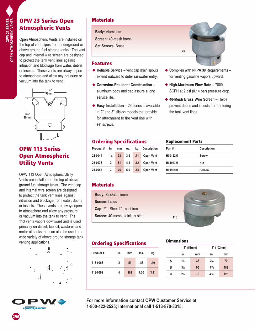
OPW 23 Series Open Atmospheric Vents
Open Atmospheric Vents are installed on the top of vent pipes from underground or above ground fuel storage tanks. The vent cap and internal wire screen are designed to protect the tank vent lines against intrusion and blockage from water, debris or insects. These vents are always open to atmosphere and allow any pressure or vacuum into the tank to vent.
OPW 113 Series Open Atmospheric Utility Vents
OPW 113 Open Atmospheric Utility Vents are installed on the top of above ground fuel storage tanks. The vent cap and internal wire screen are designed to protect the tank vent lines against intrusion and blockage from water, debris or insects. These vents are always open to atmosphere and allow any pressure or vacuum into the tank to vent. The 113 vents vapors downward and is used primarily on diesel, fuel oil, waste-oil and motor-oil tanks, but can also be used on a wide variety of above ground storage tank venting applications.
Materials
Features
Materials
23
Body: AluminumScreen: 40-mesh brassSet Screws: Brass
u Reliable Service – vent cap drain spouts extend outward to deter rainwater entry.
u Corrosion-Resistant Construction – aluminum body and cap assure a long service life.
u Easy Installation – 23 series is available in 2" and 3" slip-on models that provide for attachment to the vent line with set screws.
u Complies with NFPA 30 Requirements – for venting gasoline vapors upward.
u High-Maximum Flow Rate – 7000 SCFH at 2 psi (0.14 bar) pressure drop.
u 40-Mesh Brass Wire Screen – Helps prevent debris and insects from entering the tank vent lines.
Ordering SpecificationsProduct # in. mm oz. kg Description
23-0044 11/2 38 3.8 .11 Open Vent
23-0033 2 51 4.3 .12 Open Vent
23-0055 3 76 5.0 .14 Open Vent
Replacement Parts
Part # Description
H00122M Screw
H01967M Nut
H01969M Screen
Ordering Specifications
Product # in. mm lbs. kg
113-0066 2 51 .88 .40
113-0099 4 102 7.50 3.41
Dimensions
2" (51mm) 4" (102mm)
in. mm in. mm
A 11/2 38 23/4 70
B 33/4 95 77/16 189
C 23/4 70 415/16 125
Body: Zinc/aluminumScreen: brassCap: 2" - Steel 4" - cast ironScreen: 40-mesh stainless steel 113
For more information contact OPW Customer Service at 1-800-422-2525; International call 1-513-870-3315.

297
OPW
199
ASV
AN
TI-S
IPH
ON
VA
LVE
83/32"(21cm)
OR61/2"
(16.5cm)
OPW 199ASV Anti-Siphon Valve
The OPW 199ASV Anti-Siphon Valve is
designed to help prevent siphoning of an
above ground storage tank should a leak
or break occur in the fuel supply line.
The 199ASV installs on the top of an
above ground storage tank with a suction
rod on the inlet and the fuel supply line
(to a remote pump) on the outlet of the
valve. A poppet in the valve remains
normally closed, isolating the tank from
siphoning. When the remote pump is
activated, it overcomes a factory-adjusted
spring set to a predetermined hydrostatic
head pressure and allows fl ow of fuel
out of the AST. An internal pressure
relief valve helps absorb thermal expansion
in the fuel supply line. The 199ASV is
available in female NPT threads with
four different factory-adjusted hydrostatic
head pressure settings.
• 8 3/32" model for 11/2" and 2"(20.55cm model for 3.81cm and 5.08cm)
• 61/2" model for 3/4" and 1"(16.51cm model for 1.90cm and 2.54cm)
Listings and Certifi cations
Warning: Do not disassemble.Do not field adjust.
Features
Materials
Aboveground Storage Tank
199ASV Anti-Siphon Valve
Top of Tank
A
Lowest Point of Fuel Supply Line
199ASV
Body: Clear anodized aluminum
Bonnet: Powder-coated aluminum
Cap: Powder-coated aluminum
Spring: Stainless steel
Poppet: Hard-coated aluminum
Screw: Hard-coated aluminum
Poppet Seal: Nitrile
Ordering Specifi cationsHydrostatic
HeadPressure*
Product # in. mm lbs. kgs (Dimension A)
199ASV-1075 3/4 19 1.6 .725 0'-5'
199ASV-2075 3/4 19 1.6 .725 5'-10'
199ASV-3075 3/4 19 1.6 .725 10'-15'
199ASV-1100 1 25 1.6 .725 0'-5'
199ASV-2100 1 25 1.6 .725 5'-10'
199ASV-3100 1 25 1.6 .725 10'-15'
199ASV-1150 11/2 38 2.0 .907 0'-5'
199ASV-2150 11/2 38 2.0 .907 5'-10'
199ASV-3150 11/2 38 2.0 .907 10'-15'
199ASV-1200 2 51 2.0 .907 0'-5'
199ASV-2200 2 51 2.0 .907 5'-10'
199ASV-3200 2 51 2.0 .907 10'-15'
PSI ft. H2O in. H2O in. Hg ft. Gas ft. Diesel
0-5 1.88 4.33 51.96 3.85 6.2 5.35
5-10 3.68 8.48 101.76 7.53 12.12 10.47
10-15 5.6 12.92 155.04 11.47 18.51 15.95
15-20 7.4 17.07 204.84 15.16 24.4 21.07
uFactory-Adjusted Hydrostatic Head Pressure Settings – allow for quick, safe and easy installation on above ground tanks.
uInternal Pressure Relief Valve – helps protect piping and fi ttings from damage due to thermal expansion.Set to operate between 20 to 40 PSI (1.3 to 2.7 bar).
uAluminum Bodies – compatible with gasoline, diesel, kerosene, ethanol, methanol, fuel oil and jet fuels.
uTemperature Rating – -20°F - 120°F(29°C - 49°C)
Valve Ratingft of gasoline
S.G. = 0.7
*Note: Head Pressure calculated for gasoline.
Approximate Cracking Pressure
*Note: Some suction pumps may not have enough horsepower to open valve properly.

298
OPW
821
SO
LEN
OID
VA
LVE
A
BC
D
OPW 821 Solenoid Valve
The OPW 821 Solenoid Valve is designed
to prevent accidental siphoning of
above ground storage tanks if a leak
or break occurs in the fuel supply line.
The 821 valve is a two-way, normally
closed diaphragm valve that opens when
energized to allow fuel to fl ow to the
pump or dispenser. Available in female
NPT threads.
OPW 82RVThermal Pressure Relief Valve
To Dispenser
OPW 821Solenoid
Valve
OPW 82RVThe 82RV is designed to give thermal pressure relief to our 821 Series Solenoid Valve line. Made of allstainless steel construction with a Viton® seal, it is suitable for all petroleum products. The 82RV is precision setat the factory at 25 PSI (1.7 bar), andis fi eld adjustable from 5 to 30 psi (.34 to 2 bar).
Features
Materials
u Aluminum Body - compatible with gasoline, diesel, kerosene, low grades ethanol/methanol, fuel oil and jet fuels.
u Strainer - strainer with 100-mesh screen is recommended at the inlet.
u Mount - vertical.
u Explosion Proof Shell & Water-Tight
u Standard Operation - 120/60 volts AC.
u Thermal Expansion
u Power Draw - 20 Watts @ 60 Hz.
Body: Aluminum
Diaphragm: Viton®
Seals & Disc: Viton®
Springs: Stainless steel
Rider Rings: Tefl on®
Disc Holder: Nylon
Core Guide: Acetal, delrin
Core & Plugnut: Stainless steel
DimensionsA B C D
Product # in. mm in. mm in. mm in. mm
821-0075AC 3.31 84 3.64 92 4.46 113 2.33 59
821-0100AC 5.00 127 5.59 142 6.84 174 5.38 137
821-0150AC 5.00 127 5.59 142 6.84 174 5.38 137
821-0200AC 6.09 155 5.94 151 7.47 190 6.31 160
Ordering Specifi cationsOperatingPressure
OperatingPressure
NPT Size General *CV Fluid Differential (PSI) Differential (BAR) Weight Mounting
Product # in. mm Purpose Flow Temp. Min. Max. Min. Max. lbs. kg Position
821-0075AC 3⁄4 19 AC 5.1 125 0 50 0 3.4 2.75 1.25 Any Position
821-0100AC 1 25 AC 21 125 0 25 0 1.7 5.25 2.38 Upright & Vertical
821-0150AC 11⁄2 38 AC 35 125 0 25 0 1.7 7.25 3.29 Upright & Vertical
821-0200AC 2 51 AC 60 125 0 25 0 1.7 7.25 3.29 Upright & Vertical
821-0200AC2"
821-0100AC 1"
821-0075AC3/4"
821-0150AC1-1/2"
OPW 82RV - Thermal Pressure Relief Valve
Product #NPT Size
Operating Pressure 25 psi, Stainless Steel Construction
Weight
in. mm lbs. kg
82RV-2505 1⁄2 19 .25 .113
*CV Flow: GPM @ 1 psi Pressure Drop
82RV-2505 Series Pressure Relief Valve Instruction Sheet Order Number: 200517
CSA Certifi ed UL Listed
Listings and Certifi cations

299
OPW
21B
V FU
LL P
OR
T TW
O-W
AY
BA
LL V
ALV
ESOPW 21BV Full Port Two-Way Ball Valve
OPW Ball Valves are used throughout fueling systems where a shut-off point is desirable to isolate a section of the piping system. These full-port, forged brass valves feature a manual open-close arm and a quick quarter-turn handle, allowing easy shut down of your AST or UST system. Compatible with gasoline, alcohol fuels, diesel and MTBE. Available with Lockable Handle (LH).
Listings and Certifications
Featuresu Pressure rated to 600 psig (41 bar) WOG
u Blowout-proof stem
u Chrome-plated brass ball
u Secondary O-ring stem seal
u PTFE seats, thrust bearing and stem packing
D
B
A
C
Ordering Specifications and DimensionsDimensions (in.)
Model # Size (in.) A B C D
21BV-0050 1/2 0.59 2.28 1.81 3.35
21BV-0075 3/4 0.78 2.51 2.36 4.29
21BV-0100 1 0.98 2.97 2.52 4.29
21BV-0150 11/2 1.57 3.87 2.72 5.63
21BV-0200 2 1.96 4.29 3.03 5.63
21BV-0200SS 2 1.96 4.80 3.66 7.09
21BV-0300 3 3.15 6.10 5.12 8.35
*SS denotes Stainless Steel.
202233 Lockable Handle Kit for 1/2" Model
202234 Lockable Handle Kit for 3/4" and 1" Models
202235 Lockable Handle Kit for 1-1/2" and 2" Models
21BV
Materials
Body: Brass
Ball: Hard chrome plated
Seal: Teflon®

300
OPW
178S
SER
IES
EXTE
RNAL
AST
EME
RGEN
CY
SHUT
-OFF
VAL
VE OPW 178S Series External AST Emergency Shut-Off Valve
The OPW 178S Series External AST Shut-Off Valve is designed to shut off product flow from an above ground storage tank, bulk loading rack or any place in the fuel supply line in the event of a fire. The 178S installs in-line on fuel supply piping. A fusible link attached to a spring-operated lever holds the poppet normally open. In the event of a fire, the fusible link melts at 160˚ F, allowing the spring-actuated poppet to shut off the flow of product in the fuel supply line. The 178S is available in 2" female NPT connections.
A
1
3
45
67 8 9
C
B
16
17
13
1413
1211
10
2
Dimensions
in. mm
A 517/32 140
B 31/16 78
C 31/16 62
Features
Materials
u 178S Ductile Iron Construction – valve is manufactured from a ferrous metal to resist fracturing from high temperatures.
u Full-Bore Inside Diameter for Superior Flow Rates – maximizes flow rates in the fuel supply lines.
u Protected Main Poppet Disc – main poppet seal is held out of the main flow stream and protected from damage due to dirt or debris in the fuel.
u Compensator Ring on Main Poppet Carrier – ensures full seating of the main poppet for a tight seal.
u Viton® Main Disc and Stem Seat – compatible with gasoline, diesel, kerosene, ethanol, methanol, MTBE, fuel oil, mogas, motor oil and various other blends of fuel.
u Rated At Normal Pressure Limit of 125 psi (8.6 bar) (cold)
u Non-Shock Pressure Limit of 200 psi (13.8 bar)
u Temperature Limit 225˚ F
Body and Cap: Ductile ironPacking Nut and Stem: Stainless steelDisc: Viton®
Stem Seat: Viton®
Seat Ring: BrassCap and Packing Nut Seals: Viton®
(Valve Shown in Closed Position)
(Valve Shown in Open Position)
Ordering SpecificationsProduct # in. mm lbs. kg
178S-6130 2 51 5.35 2.43
Replacement Parts
Key Part No. Description1 H05973M Spring2 H12070M O-ring (Viton®)3 H7635RB Packing Nut4 H10445M O-ring (Viton®)5 H01344M Fusible Link Sub-Assy.6 H01505RB Pin7 C01533RB Stem8 H07644M Set Screw9 H07642ZA Lever10 H03295M Washer11 H04035M Disc Nut12 H12071R Disc (Viton®)13 H10004A Disc Holder14 H11293M Compensating Ring15 C03144M Carrier16 H11547DI Cap17 H10003M Retaining Ring
For more information contact OPW Customer Service at 1-800-422-2525; International call 1-513-870-3315.

301
OPW
SW
ING
CHEC
K VA
LVESOPW Swing Check
Valve
The OPW Swing Check Valves are designed to allow one-way product flow in fuel supply lines. OPW Swing Check Valves are installed in-line on fuel supply or transfer piping. A free-swinging poppet in the valve opens with flow of product and closes to prevent back-flow. The swing check valves can be located in either horizontal or vertical piping. The 175 is available in 2" female NPT connections. The 175B is similar to the 175 except it has an internal pressure relief valve to help absorb thermal expansion in the fuel supply or transfer line, pressure relief set at approx. 25 psi (1.7 bar). The 1175 is available in 3" female NPT connections.
A
1
C
B
98
5
7
3
Dimensionsin. mm
A 71/2 191
B 73/16 183
C 219/32 66
Features
Materials
Body: BronzeSeat Ring: BrassDisc: Viton®
Cap: Bronze
u Viton Main Disc - compatible with gasoline, diesel, kerosene, ethanol, methanol, MTBE, fuel oil, mogas, motor oil and various other blends of fuel.
u Full-Bore Inside Diameter for Superior Flow Rates – maximizes flow rates in the fuel supply lines.
u Easy Service Entry – threaded cap assembly allows removal, replacement or servicing of the carrier, disc or disc holder.
u Rated Normal Pressure Limit: 125 psi (8.6 bar)
u Cold Non-Shock Pressure Limit: 200 psi. (13.8 bar)
u Temperature Limit: 225˚ F
Ordering Specifications
Product # in. mm lbs. kg
175-0044 2 51 4.7 2.14
175B-1544 2 51 4.6 2.10
1175-0050 3 76 16.8 7.60
Replacement Parts
OPW 175, 175B, 1175
Key Part # Description
1 (175,175B) H00409RB Pin
1 (1175) H06797RB Stem
2 (175,175B) H00404RB Plug
2 (1175) H06798RB Plug
3 (175,175B) H00642B Cap
3 (1175) H06800B Cap
4 (175,175B) H12071R Disc
4 (1175) H06799 Disc Sub-Assy.
5 (175, 175B) H04035M Disc Nut
6 (175) H07488A Disc Holder
6 (175B) H07495A Disc Holder
7 (175, 175B) H07610RB Carrier
7 (1175) H06796B Carrier
8 (175, 175B) H05792M Retaining Ring
9 (175, 175B) H03295M Washer
10 (1175) H04250M Lock Nut
Swing Check Valve
4

302
AB
OVE
GR
OU
ND
PR
OD
UC
TS F
UEL
C
OM
PATI
BIL
ITY
MA
TRIX
Dispensing Description Unleaded
Fuels up to 10% Ethanol
Petroleum Diesel
Up to 15%
Ethanol
Up to E85
E100Bio-Diesel Av-
GasJet Fuel
Kerosene/ Fuel OilB5 B20
11A Series Automatic Conventional Nozzles UL/ULC X * X
11AP Series Automatic Conventional Nozzles UL/ULC X
11AF Series Farm Nozzles UL/ULC X * X
11APF Series Farm Nozzles UL/ULC X
11B® SeriesPressure Sensing Automatic Conventional Nozzles
UL/ULC X * X
11BP SeriesPressure Sensing Automatic Conventional Nozzles
UL/ULC X
21Ge SeriesPressure Sensing Automatic Nickel Plated Conventional Nozzles
UL UL UL X
7H SeriesAutomatic High Flow Conventional Nozzles
UL/ULC X * X
7HB SeriesPressure Sensing Automatic High Flow Conventional Nozzles
UL/ULC X * X
12VW Series Vacuum Assist Nozzles UL
11VA Series Vacuum Assist Nozzles UL
11VF Series Balance Nozzles UL
311/811 Series General Duty Manual Nozzles UL UL X * X
190/210/295SC Series
Manual Bulk Nozzles X X X X * X
295SAJ Manual Jet Fuel Nozzle X X X
295SA/SAC Series Manual Av-Gas Nozzles X X X X X
1290 Series Automatic Bulk Fueling Nozzles X X X X * X
241 Swivels Two Plane Hose Swivels UL/ULC UL/ULC X X * X
241TPS-0492 Nickel Plated Two Plane Hose Swivels UL UL UL X X * X
45 Swivels Two Plane Hose Swivels UL/ULC UL/ULC X X * X
36S Swivels Straight Swivels UL UL X * X
20S Swivels Two Plane Hose Swivels - Cold Weather UL/ULC UL/ULC X X * X
25 Swivels Bulk Straight Swivel X X X X * X X X
66V Series Breakaways
Single Use Conventional Breakaways UL/ULC UL/ULC X X * X
66V-0492Nickel Plated Single Use Conventional Breakaways
UL UL UL X X * X
66 Series Breakaways
Various Reconnectable and Single Use Vac Assist Breakaways
UL/ULC UL/ULC X X * X
38CS Adaptor Balance Adaptor X X X X * X
VaporSaver™ 1 Tank Pressure Management System UL / ATEX
CVS2™ Central Vacuum System UL
UL - UL listed X - Compatible ULC - UL Canada *Pending Investigation
Revised 12/1/2010
Above Ground Products Fuel Compatibility Matrix

303
AB
OVE
GR
OU
ND
PR
OD
UC
TS F
UEL
C
OM
PATI
BIL
ITY
MA
TRIX
Revised 12/1/2010
Above Ground Storage Tank Equipment Fuel Compatibility Matrix
Above Ground Storage Tank Products Description
UnleadedFuel
Petroleum Diesel
Up to 15% Ethanol
E85 / E100
Bio-DieselAv-Gas Jet Fuel
Kerosene/ Fuel OilB2 B5 B20
523V Series Pressure Vacuum Vent UL UL UL X X X X X X UL
623V Series Pressure Vacuum Vent UL UL UL X X X X X X UL
61VSA-1020-EVR Vapor Swivel Adaptor X X X X X X X X X X
1611AVB-1625 Vapor Adaptor X X X X X X X X X X
1711T-7085-EVR Vapor Cap X X X X X X X X X X
1711LPC-0300 Low Profile Vapor Cap X X X X X X X X X X
301 & 201 Series Emergency Vents UL UL UL X X X X X X UL
200TG Series AST Mechanical Gauge UL UL UL X X X X X X UL
444TA Series Tank Alarms ETL ETL ETL X X X X X X ETL
821 Series Solenoid Valves UL UL UL X X X X UL
21BV SSFull Port Stainless Steel Ball Valves
UL UL UL X X X UL
331 / 332 Series AST Spill Containers UL/ULC UL/ULC UL/ULC X X X X X X UL/ULC
61ƒ STOP AST Overfill Valve UL/ULC UL/ULC UL/ULC X X ULC
61ƒ STOP - A or M Version AST Overfill Valve Anodized UL/ULC UL/ULC UL/ULC X X X X X ULC
UL - UL listed X - Compatible ULC - UL Canada

304
OPW
PA
TEN
TS A
BO
VE G
RO
UN
D
STO
RA
GE
TAN
K E
QU
IPM
ENT
OPW Patents - Above Ground Products
Nozzles
Patent No. Country
5645115 USA
5454602 USA
5813443 USA
5620030 USA
5435357 USA
5577538 USA
6851628 USA
6951229 USA
93130770 Taiwan
7134580 USA
6024140 USA
9178054.4 EPC
5832970 USA
Breakaways
5695221 USA
5564471 USA
5570719 USA
5529085 USA
Vapor Recovery Systems & Dispensers
6834686 USA
ZL03164816.9 China
2003-326774 Japan
4108438.9 Hong Kong
6174351 USA
APP12-193908 USA
5636667 USA
5484000 USA
6648175 USA
6575206 USA
5494409 USA
EP1438506 EPC
Island Forms
Patent No. Country
6,099,202, 6,375,384B1 USA
1227417C China
2,322,216 Canada
221,155 Mexico
Storage Tank Emergency Vent Valve (AST)
5,141,020 USA
723V Pressure Vacuum Vent
61/033571 USA
Storage Tank Shut-Off Valve (61ƒSTOP) AST
5,472,012 USA
5,850,849 USA
Tank Gauge (AST)
6,523,404, 7,174,784 USA
P10501119-1 Brazil
2492346 Canada
94100860 Taiwan
05-10002326.9 China
22/che/2005 India
2005-7183 Japan
4005/2005 Korea

305
OPW
PA
TEN
TS A
BO
VE G
RO
UN
D
STO
RA
GE
TAN
K E
QU
IPM
ENT
305
OPW
APP
RO
VALS
/ LI
STIN
GS
AB
OVE
GR
OU
ND
PR
OD
UC
TSOPW Approvals / Listings Above Ground Products
UL Listed Products
Product: Description: File Number:
11A Series & Astro Automatic Nozzle MH1942
11B Series & AstroB Pressure-Sensing Automatic Nozzle MH1942
1A Series Automatic Nozzle MH1942
7H Series Automatic Nozzle MH1942
7HB Series Pressure-Sensing Automatic Nozzle MH1942
44 & 44N Flow Limiters MH27237
11AF Farm Nozzle MH1942
21Ge Pressure-Sensing Automatic Nozzle for E85 MH1942
241TPS Two-Plane Swivel MH4542
241TPS-0492 Two-Plane Swivel for E85 MH4542
45 Hose Swivel MH5452
20S Hose Swivel MH12551
66REC 3/4" Reconnectable Breakaway MH18037
66RB 1" Reconnectable Breakaway MH17834
66V Breakaway MH18037
66V-0492 Breakaway for E85 MH18037
66SB Swivel Breakaway MH17834
36S Hose Swivel MH4542
21Gv Vacuum-Assist Nozzle for ORVR MH1942
12VW Vacuum-Assist Nozzle MH1942
AstroVac Vacuum-Assist Nozzle MH1942
11VAI Series Vacuum-Assist Nozzle MH1942
11VAA Series Vacuum-Assist Nozzle MH1942
66CAS Dry Reconnect Inverted Breakaway MH18037
66ISU Vacuum-Assist Vapor Recovery Breakaway MH17834
66ISB Vacuum-Assist Vapor Recovery Breakaway MH17834
MFVA Vacuum-Assist Vapor Recovery Swivel MH17834
66FL-1000 Vacuum-Assist Flow Limiter MH10040
11VF Balance Nozzle MH1942
66CL/CSU/CLP Coaxial Breakaways MH18037
38CS Balance Adaptor MH10040
X44TA-0100 Liquid-Level and Overfill Alarm ETL302278-HO1
44TA-LLFS Liquid-Level Float Switch Sub Assembly E177423
199ASV Anti-Siphon Valve MH8488
523, 523V, 523AV Pressure/Vacuum Vents MH10040
623V XXXX Pressure Vacuum Vent MH27236 Listed 644R
821 Series Solenoid Valve E12264
200TG Mechanical Tank Gauge MH29367
211-AST AST Spill Container MH25724
202 Series Emergency Vents MH25724
301 Series Emergency Vents MH25724
VaporSaver™ 1 Tank Pressure Management System MH10040
61ƒ STOP-XXXT Version AST Overfill Valve MH25724

306
OPW
APP
RO
VALS
/ LI
STIN
GS
AB
OVE
GR
OU
ND
PR
OD
UC
TS OPW Approvals / Listings Above Ground Products ULC Listed Products
Product: Description: File Number:
11A Series & Astro Automatic Nozzle MH27234
11B Series & AstroB Pressure-Sensing Automatic Nozzle MH27234
1A Nozzle Automatic Nozzle MH27234
7H Series Automatic Nozzle MH27234
7HB Series Pressure-Sensing Automatic Nozzle MH27234
44 & 44N Flow Limiters MH27237
11AF Farm Nozzle MH27234
241TPS Two-Plane Swivel MH27235
20S Hose Swivel MH27235
45 Hose Swivel MH27235
66SB 3/4" Swivel Breakaway MH27235
66REC Reconnectable Breakaway MH27235
66RB 1" Reconnectable Breakaway MH27235
66V Breakaway MH27235
61ƒSTOP-XXXX Series Overfill Prevention Valve MH25724, MH21147
61ƒSTOP-XXXXT Series Overfill Prevention Valve MH25724, MH21147
331 / 332 Series AST Spill Containers MH19391
MoPETP (Missouri Performance Evaluation Testing Procedures)
11VF-47 Balance Nozzle MoPETP 99-03
66CL/CSU/CLP Coaxial Breakaway MoPETP 99-03
523V Pressure/Vacuum Vent APCP-0002-001-99
Florida
211AST, 211 REMOTE AST Spill Containers EQ-226
61ƒSTOP Series AST Overfill Prevention Valve EQ-225
New York City Fire Department Certification Number
61ƒStop AST Overfill Prevention Valve 4949
KIWA Approvals
199-ASV Anti-Siphon Valve K22656/01
Other VaporSaver Approvals
ATEX – SIRA 03ATEX 9535 Texas ORVR Certification Approval Letter: 12/01/04
TUV – 97-11.1 Mexico – SEGEMDGPCCAT- MTSRVDOVER/001/2004
Independent 3rd Party Certified C-030501 Japan – KHK File# 16-4-5
MDE Regulation Chapter 02.03 c(5)b

307
OPW
APP
RO
VALS
/ LI
STIN
GS
AB
OVE
GR
OU
ND
PR
OD
UC
TSCARB AST EVR Certified Products
CARB / Fire MarshalProduct Description CARB Certification CA Fire Marshal
12VW Vacuum-Assist NozzleG-70-153G-70-150G-70-199
GVRC: 005:008:059
11VAI-27Vacuum-Assist Nozzle w/o Vapor Valve
G-70-150G-70-150/94-8
G-70-199
GVRC: 005:008:050 (applies to all)
11VAI-37 Vacuum-Assist Nozzle w/o Vapor Valve
G-70-164/95-29G-70-199
GVRC: 005:008:050(applies to all)
11VAI-68 Vacuum-Assist Nozzle
G-70-154G-70-163G-70-169G-70-199
GVRC: 005:008:050(applies to all)
11VAI-69 Vacuum-Assist NozzleG-70-153G-70-199
GVRC: 005:008:050 (applies to all)
11VAA-61 Vacuum-Assist Nozzle G-70-118 GVRC: 005:008:049
66CAS Dry Reconnect Inverted Breakaway 96-18 GVRC: 005:008:056
66ISU Vacuum-Assist Breakaway 94-9 GVRC: 005:031:009
66ISB Swivel/Breakaways 95-35 GVRC: 005:031:016
11VF-47 Balance Nozzle G-70-52 GVRC: 005:008:037
66CL/CSU/CLP Coaxial Breakaway 91-14 GVRC: 005:008:047
Vacurite®
00-40005CCentralized Vacuum-Assist Vapor Recovery System
G-70-164-AAG-70-175 GVRC: 004:001:001
Max Vacurite® AST 00-40001C
Centralized Vacuum-Assist Vapor Recovery System
G-70-164-AAG-70-175-AST GVRC: 004:001:001
Micro Vacurite®
00-40003.ULCentralized Vacuum-Assist Vapor Recovery System
98-13G-70-164-AA GVRC: 004:001:002
VacuSmart™ Air to Liquid Test Equipment CARB ApprovedAlternative to TP-201.5 N/A
VacuChek™ Air to Liquid Test Equipment CARB ApprovedAlternative to TP-201.5 N/A
VaporSaver™ Tank Pressure Management System G-70-204A GVRC: 005:008:062
61fSTOP AST Overfill Valve CARB No. ATG-01-01 N/A
523V Pressure/Vacuum Vent CARB No. 98-1 N/A
Product: Description: EO Number:
301-XXXX Emergency Vent EO-VR 401-B
61ƒSTOP-XXXX Overfill Prevention Valve EO-VR 401-B
331-ASTWXX & 332-ASTWXX Direct Fill Spill Container EO-VR 401-B
1611AN-XXXX & 1612AN-XXXX Kamvalok Adaptor EO-VR 401-B
634B-XXXX & 634BK-XXXX Dust Cap EO-VR 401-B
61VSA-1020-EVR Rotatable Swivel Adaptor EO-VR 401-B
1711T-7085-EVR & 1711LPC-0300 Vapor Recovery Caps EO-VR 401-B
61FT-XXXX Drop Tube EO-VR 401-B
200TG-ENG, 200TG-ENG40, 200TG-MET, 200TG-MET40
Mechanical Tank Gauge EO-VR 401-B
144TA-XXX Tank Alarm EO-VR 401-B
44TA-LLFS Liquid Level Float Switch EO-VR 401-B

FOR THOSE WHO LIKE TO GET AWAY FROM IT ALL…