abstract - wireilla.com · curves, enhancement of ... matlab/simulink, ... where v ds and v qs are...
TRANSCRIPT

International Journal of Soft Computing, Mathematics and Control (IJSCMC), Vol. 3, No. 4, November 2014
DOI : 10.14810/ijscmc.2014.3403 33
DYNAMIC RESPONSES IMPROVEMENT OF
GRID CONNECTED WPGS USING FLC IN HIGH
WIND SPEEDS
Maziar izadbakhsh
1*, Majid Gandomkar
1, Alireza Rezvani
1 and Saeed Vafaei
1
1Department of Electrical Engineering, Saveh Branch, Islamic Azad University, Saveh,
Iran
ABSTRACT Environmental and sustainability concerns are developing the significance of distributed generation (DG)
based on renewable energy sources. In this paper, dynamic responses investigation of grid connected wind
turbine using permanent magnet synchronous generator (PMSG) under variable wind speeds and load
circumstances is carried out. In order to control of turbine output power using Fuzzy Logic controller
(FLC) in comparison with PI controller is proposed. Furthermore, the pitch angle based on FLC using
wind speed and active power as inputs, can have faster responses, thereby leading to smoother power
curves, enhancement of dynamic performance of wind turbine and prevention of mechanical damages to
PMSG. Inverter adjusted the DC link voltage and active power is fed by d-axis and reactive power is fed by
q-axis (using P-Q control mode). Simulation of wind power generation system (WPGS) is carried out in
Matlab/Simulink, and the results verify the correctness and feasibility of control strategy.
Keywords
Dynamic responses, FLC, Pitch Angle, PMSG, P-Q control
1. INTRODUCTION
Renewable energy systems are of significance as being modular, nature-friendly and domestic.
Virtually, all regions of the world have renewable resources. By this point of view studies on
renewable energies concentrate more attention. Solar energy and wind energy are the two
renewable energy sources most common in use. Among those renewable energy sources, wind
energy stands as a true alternative to conventional technologies for electricity generation. Wind
energy also has the clean energy aspect which is especially important, considering the effects of
global warming [1, 2]. Fixed speed and variable speed wind turbine generator systems are
emerging in the wind power industry, although the former is rarely considered for new
installations. One of the major drawbacks of fixed speed wind turbine generator system is that it
cannot capture maximum power from the wind. A few types of variable speed wind turbine
generator systems are commercially available today. A PMSG is recognized as a promising
technology to use as a wind generator in both the direct-drive system and the system using a
simple single-stage gearbox. One of the major advantages is the high power density of this type of
machine [2, 3].
Another advantage of variable wind turbines is the capability of maximum power point tracking
(MPPT) from wind energy sources [4]. Variable speed wind turbines operate in two primary

International Journal of Soft Computing, Mathematics and Control (IJSCMC), Vol. 3, No. 4, November 2014
34
regions, below rated power and above rated power. When power production is below the rated
power for the machine, the turbine operates at variable rotor speeds to capture the maximum
amount of energy available in the wind [5, 6]. In above-rated power conditions, the primary
objective is to maintain a constant power output. This is generally achieved by holding the
generator torque constant and varying the blade pitch angle. MPPT controller somehow changes
the rotor speed according to variation of wind speed that the tip speed ratio (TSR) is maintained
in optimum value.
One of the methods to reach the maximum power point (MPP) is pitch angle control (B). In high
speeds wind the extra production of active power via wind turbine lead to increases consuming of
reactive power in generator and in which case, it should utilizes the reactive power compensator
for injecting reactive power that has extra cost too [7]. In the past, PIDs is used mostly in
controllers design but, by introduction of fuzzy logic instead of PID, created a better performance
and best preventative way to eliminate the profound mathematical understanding of system. In
comparing PIDs and Fuzzy logic systems, fuzzy logic has more stability, faster and smoother
response, smaller overshoot and does not need a fast processor, Also it's more powerful than other
non-linear controllers [8, 9]. Some authors have already presented on variable wind turbine using
PMSG technology, including dynamic and transient characteristics [10, 11]. Various control
strategies can be adopted for the operation of the generator and grid side converter, as proposed in
[11, 12].
In these papers [13-15], pitch angle based on FLC is presented. In [15] active power and in [13,
14] both reactive power and rotational rotor speed are used as input signals and because in
mentioned items wind speed's been ignored, the controller has not fast response and may cause
mechanical damages to synchronous generator. Also, another problem in these articles that it is
not practically connected to grid [14-18], but the grid connected mode in this paper is proposed to
analyse the system performance. In recent years, many topologies based on power electronic
devices with different level of complexity and cost is developed investigated in order to connect a
PMSG to network. There are two modes for inverter operating: 1) Active and reactive control
mode (P-Q control), 2) Voltage and frequency control mode (V-F control) [19, 20].
Analysis performance of grid connected PMSG wind turbine in P-Q control mode under load
circumstances and variable wind speeds and also, enhancement of dynamic performance in
WPGS using pitch angle based on FLC is investigated. P-Q control strategy is derived from Park
transformation and it’s simulated in Matlab software. The pitch angle is designed based on FLC
by adding wind speed as an input signal to adjust the turbine output power in extra high speed.
2. STURUCTURE OF GRID CONNECTED WPGS
The diagram of a WPGS based on PMSG integrated to grid is illustrated in Figure 1. Turbine
output is rectified by using uncontrolled rectifier. Then DC link voltage is adjusted by PI
controller until it reaches a constant value and then, the constant voltage is inverted to AC voltage
using sinusoidal PWM inverter. Inverter adjusted the DC link voltage and injected active power
by d-axis and injected reactive power by q-axis using PQ control method. Furthermore, turbine
output is regulated through pitch angle based on FLC in extra high wind speeds. By increasing
pitch angle via fuzzy controller, the exceeding power of wind turbine is limited, reaching to the
nominal value and reducing inverter output current. Therefore, by the reduction of injected output
power of wind turbine, the injection of extra total active power to grid is decreased.

International Journal of Soft Computing, Mathematics and Control (IJSCMC), Vol. 3, No. 4, November 2014
35
Figure 1. The block diagram of WPGS
2.1. Variable Wind Turbine Modelling
The amount of electricity that a turbine is able to produce depends on the speed of rotor and the
speed of the wind that propels the rotor [21, 22]. Aerodynamic wind power is calculated in
equation (1).
3
p w(P 0 AC ).5 , V= λ βρ (1)
W
λ = m
w
R
V (2)
Where P, ρ , A , Vw, Wm and R are power, air density, rotor swept area of the wind turbine ,
wind speed in m/sec, rotor speed in rad/sec and radius of turbine respectively. Also, Cp is the
aerodynamic efficiency of rotor.
21
p
116C , 0.5176 0.) 4 5(
−
λ β = − −
iλ
i
β e λ
(3)
1
i 3
1 0.035
0.08 1
− λ = − + + λ β β
(4)
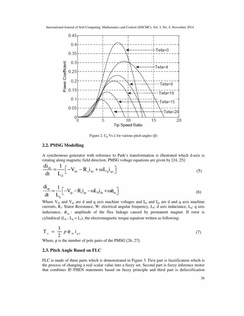
Furthermore, the Cp depends on TSR and blade pitch angle. Figure 2 shows the typical variation
of Cp respect to the TSR or various values of the pitch angle (β) [23].
International Journal of Soft Computing, Mathematics and Control (IJSCMC), Vol. 3, No. 4, November 2014
36
Figure 2. Cp Vs λ for various pitch angles (β)
2.2. PMSG Modelling
A synchronous generator with reference to Park’s transformation is illustrated which d-axis is
rotating along magnetic field direction. PMSG voltage equations are given by [24, 25]:
dsds s ds q qs
d
di 1V R i ωL i
dt L = − − + (5)
qs
qs s qs d ds m
q
di 1V R i ωL i ω
dt L = − − − + φ (6)
Where Vds and Vqs are d and q axis machine voltages and Ids and Iqs are d and q axis machine
currents, Rs: Stator Resistance, W: electrical angular frequency, Ld: d axis inductance, Lq: q axis
inductance, mφ : amplitude of the flux linkage caused by permanent magnet. If rotor is
cylindrical (Ld ≈ Lq = Ls), the electromagnetic torque equation written as following:
e
3T
2= φ m q sp i (7)
Where, p is the number of pole pairs of the PMSG [26, 27].
2.3. Pitch Angle Based on FLC
FLC is made of three parts which is demonstrated in Figure 3. First part is fuzzification which is
the process of changing a real scalar value into a fuzzy set. Second part is fuzzy inference motor
that combines IF-THEN statements based on fuzzy principle and third part is defuzzification

International Journal of Soft Computing, Mathematics and Control (IJSCMC), Vol. 3, No. 4, November 2014
37
which is the process that changes a fuzzy set into a real value in output [28, 29].
Figure 3. The Structure of FLC System
Proposed FLC is consisting of two input signal and one output signal. The first input signal is
based on deviation between active power from the rated value in P.U and it’s mentioned as error
signal. Thus, positive value indicate turbine’s normal operation and negative value shows the
extra power generation during above rated wind speed. In this case, controller should modify in
pitch angle degree which is done by increase the nominal value. The pitch angle degree is
regulated on zero in a normal condition, the whole wind energy can be converted to mechanical
energy and when the pitch angle start to increase from zero value, the wind attach angle to blades
is increase that lead to aerodynamic power reduction and consequently the output power is draw
down. Besides, the second signal taken from anemometer which is located on top of nacelle.
Controller’s response is so faster when wind speed is used as an input signal comparing to the
time that inputs are rotor rotational speed, reactive power and active power in large turbines with
high moment of inertia [13-15]. However, mechanical erosion in large and high speed turbines is
diminished by adjusting the FLC. Designing of pitch angle based on FLC for wind turbine power
adjustment in high wind speeds, is being proposed. By increasing pitch angle via fuzzy controller,
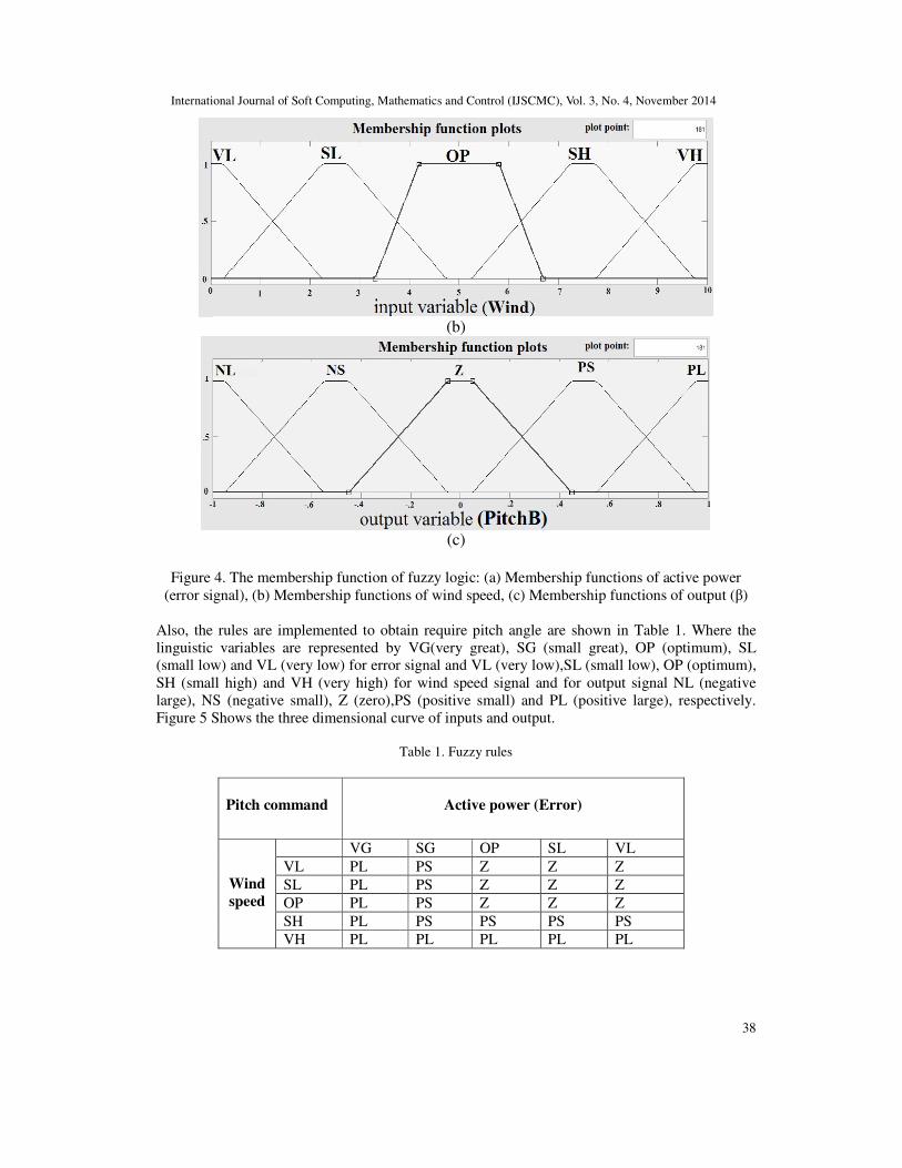
the exceeding power of wind turbine is limited, reaching to the nominal value. Three Trapezoidal
membership functions are considered in this paper. Also Min-Max method is used as a
defuzzification reference mechanism for centroid. Given membership functions are shown in
Figure 4.
(a)
International Journal of Soft Computing, Mathematics and Control (IJSCMC), Vol. 3, No. 4, November 2014
38
(b)
(c)
Figure 4. The membership function of fuzzy logic: (a) Membership functions of active power
(error signal), (b) Membership functions of wind speed, (c) Membership functions of output (β)
Also, the rules are implemented to obtain require pitch angle are shown in Table 1. Where the
linguistic variables are represented by VG(very great), SG (small great), OP (optimum), SL
(small low) and VL (very low) for error signal and VL (very low),SL (small low), OP (optimum),
SH (small high) and VH (very high) for wind speed signal and for output signal NL (negative
large), NS (negative small), Z (zero),PS (positive small) and PL (positive large), respectively.
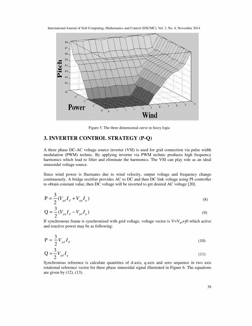
Figure 5 Shows the three dimensional curve of inputs and output.
Table 1. Fuzzy rules
Pitch command
Active power (Error)
Wind
speed
VG SG OP SL VL
VL PL PS Z Z Z
SL PL PS Z Z Z
OP PL PS Z Z Z
SH PL PS PS PS PS
VH PL PL PL PL PL
International Journal of Soft Computing, Mathematics and Control (IJSCMC), Vol. 3, No. 4, November 2014
39
Figure 5. The three dimensional curve in fuzzy logic
3. INVERTER CONTROL STRATEGY (P-Q)
A three phase DC-AC voltage source inverter (VSI) is used for grid connection via pulse width
modulation (PWM) technic. By applying inverter via PWM technic produces high frequency
harmonics which lead to filter and eliminate the harmonics. The VSI can play role as an ideal
sinusoidal voltage source.
Since wind power is fluctuates due to wind velocity, output voltage and frequency change
continuously. A bridge rectifier provides AC to DC and then DC link voltage using PI controller
to obtain constant value, then DC voltage will be inverted to get desired AC voltage [20].
3P ( )
2= +gd d gq qV I V I (8)
3Q ( )
2= −gq d gd qV I V I (9)
If synchronous frame is synchronized with grid voltage, voltage vector is V=Vgd+j0 which active
and reactive power may be as following:
3P
2= gd dV I (10)
3Q
2=
gd q V I (11)
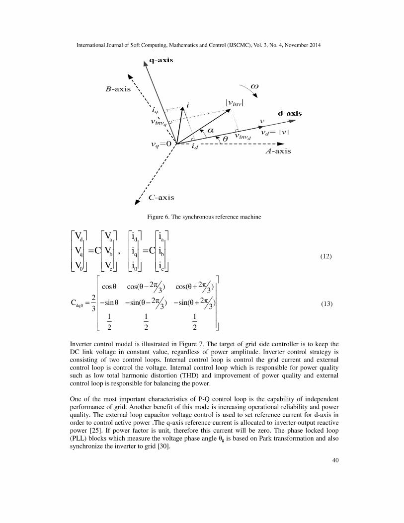
Synchronous reference is calculate quantities of d-axis, q-axis and zero sequence in two axis
rotational reference vector for three phase sinusoidal signal illustrated in Figure 6. The equations
are given by (12), (13).
International Journal of Soft Computing, Mathematics and Control (IJSCMC), Vol. 3, No. 4, November 2014
40
Figure 6. The synchronous reference machine
d a d a
q b q b
0 c 0 c
V V i i
V C V , i C i
V V i i
= =
(12)
dq0
2π 2πcosθ cos(θ ) cos(θ )3 3
2 2π 2πC sinθ sin(θ ) sin(θ )3 33
1 1 1
2 2 2
− +
− − − − +
=
(13)
Inverter control model is illustrated in Figure 7. The target of grid side controller is to keep the
DC link voltage in constant value, regardless of power amplitude. Inverter control strategy is
consisting of two control loops. Internal control loop is control the grid current and external
control loop is control the voltage. Internal control loop which is responsible for power quality
such as low total harmonic distortion (THD) and improvement of power quality and external
control loop is responsible for balancing the power.
One of the most important characteristics of P-Q control loop is the capability of independent
performance of grid. Another benefit of this mode is increasing operational reliability and power
quality. The external loop capacitor voltage control is used to set reference current for d-axis in
order to control active power .The q-axis reference current is allocated to inverter output reactive
power [25]. If power factor is unit, therefore this current will be zero. The phase locked loop
(PLL) blocks which measure the voltage phase angle θg is based on Park transformation and also
synchronize the inverter to grid [30].

International Journal of Soft Computing, Mathematics and Control (IJSCMC), Vol. 3, No. 4, November 2014
41
Figure 7. The inverter control model
4. SIMULATION RESULTS
In this section, simulation results under different terms of operation using Matlab/Simulink are
presented. System block diagram is shown in Figure 8.
PMSG parameters: Stator resistance per phase: 2.5Ω, Inertia: 0.82e-3
kg-m2, Torque constant:
12N-M/A, Pole pairs: 8, Output power: 90kW, Nominal speed: 12 m/s, Ld =La= 7.2 mH. Grid
parameters: X/R: 7, F: 60 Hz, Vgrid: 220V and other parameters, DC link capacitor: 5100µF, DC
link voltage: 1100V, Type of load: inductive, Load power: 90kW.
Figure 8. The block diagram of grid connected WPGS in Matlab/Simulink

International Journal of Soft Computing, Mathematics and Control (IJSCMC), Vol. 3, No. 4, November 2014
42
4.1. Case Study
In this case, the evaluation of FLC with comparing to conventional PI controller in pitch angle of
WPGS is carried out. The dynamic performance of WPGS under variations of wind speed and
load circumstances is investigated. There is no power exchange between WPGS and grid in
normal condition.
During 0 < t < 1 s, the load power is 90kW and at t= 1 s, it has %25 step increase in load that is
constant until t=2 s. Then, at t=3 s, it has step decrease 40% in load power, that is constant until
t=4 s. Wind speed during 0< t <5 s is 12 m/s and at t= 5 s, it is reduced to 10 m/s. Then, during 5<
t < 7, wind speed is 10 m/s and after that, at t=7 s, it is extremely increased to 19m/s. By
designing FLC, when wind speed is more than nominal speed (12 m/s), turbine output power is
increased by extremely increasing wind speed; however, with PI controller, the power is constant
at a high level and in the presence of FLC, it is reduced to the nominal power and made smoother,
thereby leading to the prevention of mechanical fatigue to generator.
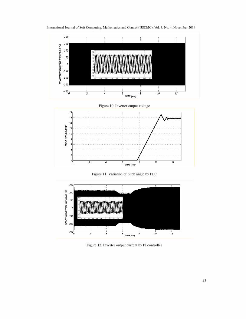
Figure 9 shows the variation of wind speed in proposed system. Inverter output voltage is
invariant, which is shown in Figure 10. The variation of pitch angle in the presence of FLC is
depicted in Figure 11. As can be seen, in normal situations, the pitch angle is set as zero. At wind
speeds above the rated wind, the extracted wind power has to be limited by increasing the pitch
angle (β). Figures 12 and 13 show the inverter output current with the PI controller and in the
presence of FLC, respectively. It shows the effectiveness of fuzzy controller by increasing pitch
angle. The exceeding power of wind turbine is limited and also, the inverter output current is
reduced by FLC in comparison to PI controller. Figures 14 and 15 show the turbine output power
with PI controller and in the presence of FLC according to variation of wind speed. By increasing
the pitch angle via FLC, the exceeding power of wind turbine is limited, reaching to the nominal
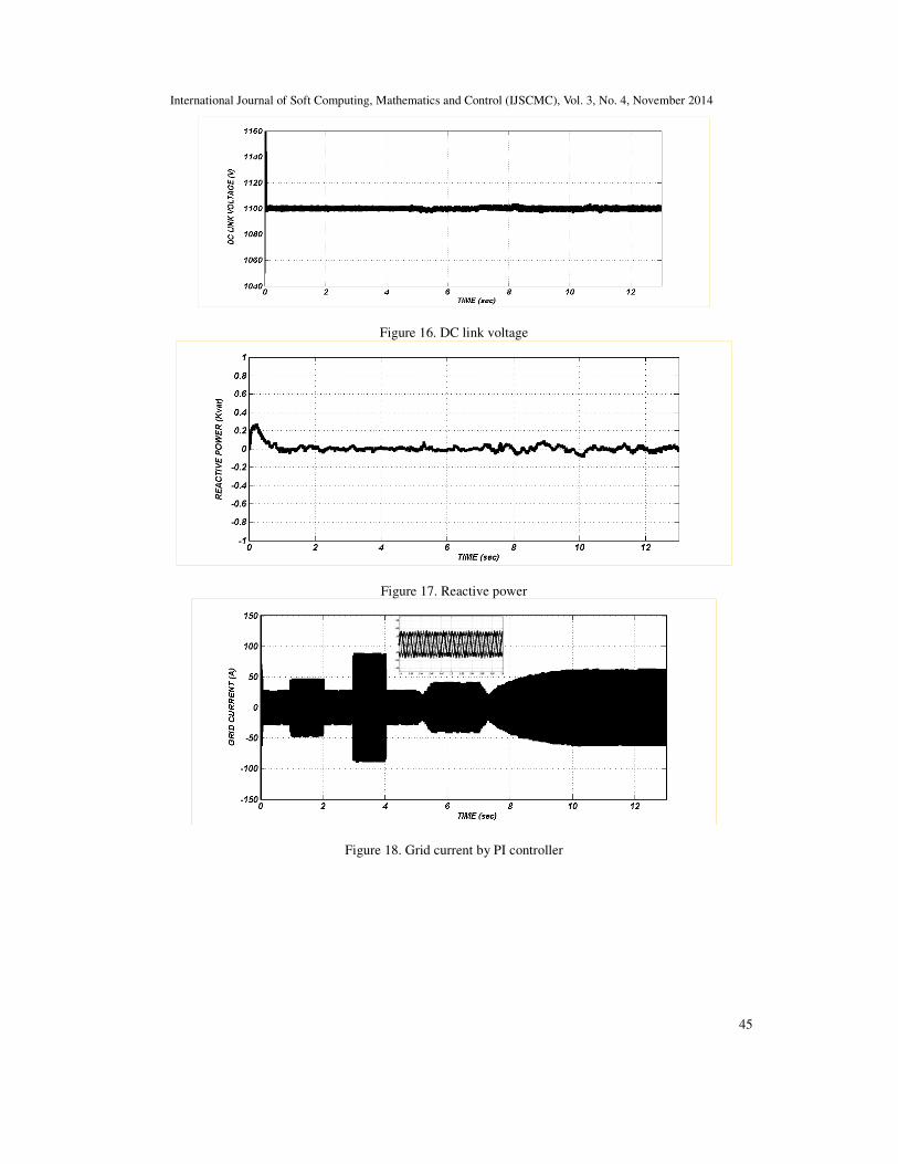
value. DC link voltage remains at a constant value (1100V), thereby proving the effectiveness of
the established P-Q controller as illustrated in Figure 16. The reactive power produced by the
WPGS is regulated at zero that, the power factor maintained unity as shown in Figure 17. The
grid current with PI controller and FLC are shown in Figures 18 and 19, respectively.
One of the most important aspects of using DG sources and connecting them to grid is keeping
the THD at the minimum of its value. According to IEEE Std.1547.2003, it should be around 5%.
In THD curve, it is around 5% to 7%, which is shown Figure 20. Grid voltage is depicted in
Figure 21. It can be observed from Figure 15, that pitch angle based on FLC can limit the
exceeding output power of wind turbine. Therefore, by the reduction of output power of wind
turbine, the injection of extra total active power to grid is declined. The exchange active powers
among grid and WPGS are illustrated in Figures 22 and 23.
Figure 9. Variation of wind speed
International Journal of Soft Computing, Mathematics and Control (IJSCMC), Vol. 3, No. 4, November 2014
43
Figure 10. Inverter output voltage
Figure 11. Variation of pitch angle by FLC
Figure 12. Inverter output current by PI controller

International Journal of Soft Computing, Mathematics and Control (IJSCMC), Vol. 3, No. 4, November 2014
44
Figure 13. Inverter output current by FLC
Figure 14. Turbine output power by PI controller
Figure 15. Turbine output power by FLC
International Journal of Soft Computing, Mathematics and Control (IJSCMC), Vol. 3, No. 4, November 2014
45
Figure 16. DC link voltage
Figure 17. Reactive power
Figure 18. Grid current by PI controller

International Journal of Soft Computing, Mathematics and Control (IJSCMC), Vol. 3, No. 4, November 2014
46
Figure 19. Grid current by FLC
Figure 20. THD (%)
Figure 21. Grid voltage

International Journal of Soft Computing, Mathematics and Control (IJSCMC), Vol. 3, No. 4, November 2014
47
Figure 22. Active powers by PI controller
Figure 23. Active powers by FLC
5. CONCLUSIONS
In the proposed paper, the dynamic responses of grid connected wind turbine using PMSG under
load circumstances and variation of wind speed was carried out. Control strategy and precise
modelling of DC/AC grid connected converter was presented. Inverter adjusted the DC link
voltage and active power was fed by d-axis and reactive power was fed by q-axis (using P-Q
control mode).
The simulation results indicated that using FLC could dramatically reduce the disadvantages of PI
method. Moreover, the presented FLC in the WPGS, by adding wind speed as an input signal,
could have faster and smoother, prevent more mechanical fatigue and also, the dynamic
performance of wind turbine could be improved. On the other hand, by increasing pitch angle via
FLC, the exceeding power of wind turbine was limited, reaching to the nominal value and
reduced inverter output current. Therefore, by the reduction of injected output power of wind
turbine, the injection of extra total active power to grid was declined. It was clear that, the WPGS
by applying FLC in pitch angle and also, with the cooperation of grid could easily meet the load
demand.

International Journal of Soft Computing, Mathematics and Control (IJSCMC), Vol. 3, No. 4, November 2014
48
REFERENCES
[1] M.Izadbakhsh, M.Gandomkar, A.Rezvani and A.Ahmadi,‘’Short-term resource scheduling of a
renewable energy based micro grid’’, Renewable Energy,Vol.75, pp.598-606, 2015.
[2] A.Rezvani, M.Gandomkar, M.Izadbakhsh and A.Ahmadi,‘’Environmental/economic scheduling of a
micro-grid with renewable energy resources’’, Journal of Cleaner Production,Vol.87, pp. 216-226,
2015.
[3] P. Vas, Electrical Machines and Drives: A Space Vector Theory Approach. New York, USA: Oxford
Univ. Press, 1992.
[4] J. F. Manwell, J. G. Mcgowan, A. L. Rogers, Wind Energy Explained: Theory, Design and
Application, John Wiley & Sons Ltd, Chichester, 2002.
[5] M.G. Simoes, B.K. Bose, and R.J. Spiegel, “Fuzzy Logic Based Intelligent Control Of A Variable
Speed Cage Machine Wind Generation System,” IEEE Transactions On Power Electronics, vol. 12,
no 1, pp.87-95, 1997.
[6] E.B.Muhandoa, T. Senjyua, H. Kinjob and T. Funabashi, “Augmented LQG controller for
enhancement of online dynamic performance for WTG system”, Renewable Energy, vol.33, pp.1942–
1952, 2008.
[7] K.Y. Lo, Y. M. Chen, and Y. R. Chang,’’ MPPT Battery Charger for Stand-Alone Wind Power
System’’, IEEE transactions on power electronics, vol. 26, no. 6, pp. 1631 – 1638, 2011.
[8] J.Y.M. Cheung, A.S. Kamal,” Fuzzy Logic Control of refrigerant flow”, UKACC International
Conference on Control, Conference Publication,Vol.96, No. 427 ,pp. 2-5 ,September 1996.
[9] Gaurav, A. Kaur," Comparison between Conventional PID and Fuzzy Logic Controller for Liquid
Flow Control: Performance Evaluation of Fuzzy Logic and PID Controller by Using
MATLAB/Simulink", International Journal of Innovative Technology and Exploring Engineering
(IJITEE), Vol.1, no.1, pp. 84-88, June 2012.
[10] M. Chinchilla, S. Arnaltes, and J. C. Busgos, “Control of permanent magnet synchronous generators
applied to variable-speed wind-energy systems connected to the grid,” IEEE Trans. Energy Convers.,
vol. 21, no. 1, pp. 130–135, Mar. 2006.
[11] S. Morimoto, T. Nakamura, and Y. Takeda, “ Power maximization control of variable-speed wind
generation system using permanent magnet synchronous generator,” IEEJ Trans. Power Energy, vol.
123, no. 12, pp. 1573–1579, 2003.
[12] N. A. Cutululis, E. Ceanga, A. D. Hansen, and P. Sørensen, “Robust multi-model control of an
autonomous wind power system,” Wind Energy, vol. 9, no. 5, pp. 399–419, 2006.
[13] X. Lingfeng, Y. Xiyun, L. Xinran, and X. Daping, "Based on adaptive fuzzy sliding mode controller,"
in Intelligent Control and Automation, WCICA 7th World Congress on china, pp. 2970-2975, 2008.
[14] C. A. M. Amendola and D. P. Gonzaga, "Fuzzy-Logic Control System of a Variable-Speed Variable-
Pitch Wind-Turbine and a Double-Fed Induction Generator", in Intelligent Systems Design and
Applications, Seventh International Conference on Brazil, pp. 252-257, 2007.
[15] T. Senjyu, R. Sakamoto, N. Urasaki, T. Funabashi, and H. Sekine, "Output power leveling of wind
farm using pitch angle control with fuzzy neural network," in Power Engineering Society General
Meeting, IEEE, Japan, pp.1- 8,2006.
[16] X. Yao, Ch. Guo and Z. Xing, Y. Li, S. Liu’’ Variable Speed Wind Turbine Maximum Power
Extraction Based on Fuzzy Logic Control’’, International Conference on Intelligent Human-Machine
Systems and Cybernetics ,China, pp.202 – 205,2009.
[17] Q. Zeng , L. Chang , R. Shao ,’’ Fuzzy-logic-based maximum power point tracking strategy for
PMSG variable-speed wind turbine generation systems ’’ , Electrical and Computer Engineering,
CCE Canadian Conference on, pp. 405-410,2008.
[18] T.L.Van , D.CH.Lee ,’’ Output power smoothening of variable - speed wind turbine systems by
pitch angle control’’ , IPEC 2012 Conference on Power & Energy, pp.166-171, 2012.
[19] A. Kahrobaeian , Y.A.-R.I. Mohamed , “Analysis and Mitigation of Low-Frequency Instabilities in
Autonomous Medium-Voltage Converter-Based Microgrids With Dynamic Loads ”, IEEE Trans. on
Industrial Electronics ,vol. 61, no.4, pp. 1643 - 1658, 2014.
[20] C.T. Lee , R.P. Jiang , P.T. Cheng , “A Grid Synchronization Method for Droop-Controlled
Distributed Energy Resource Converters”, IEEE Trans. on Industry Application, Vol.49, no.2, pp. 954
- 962, 2013.

International Journal of Soft Computing, Mathematics and Control (IJSCMC), Vol. 3, No. 4, November 2014
49
[21] Md. Arifujjaman, “Modeling, Simulation and Control of Grid Connected Permanent Magnet
Generator (PMG)-based Small Wind Energy Conversion System” IEEE Electrical Power & Energy
Conference, Canada, pp.1-6, 2010.
[22] Z. Lubosny,‘’ Wind Turbine Operation in Electric Power Systems’’, Berlin, Springer, 2003.
[23] A. Uehara , A.Pratap , T. Goya , T. Senjyu, A. Yona , N. Urasaki and T. Funabashi, “A Coordinated
Control Method to Smooth Wind Power Fluctuations of a PMSG-Based WECS” IEEE Transactions
on Energy Conversion, Vol. 26, No. 2, pp. 550-558, June 2011.
[24] M. Rosyadi , S. M. Muyeen , R. Takahashi , J. Tamura’’ Fuzzy-PI Controller Design for PM Wind
Generator to Improve Fault Ride Through of Wind Farm’’, International journal of renewable energy
research Marwan Rosyadi et al., Vol.3, No.2,pp.308-314, 2013.
[25] C. Krause, ‘’Analysis of electric machinery’’, 2nd Edition, United States of America: Willey, 2002.
[26] L. barote, C. marinescu ‘’Modeling and Operational Testing of an Isolated Variable Speed PMSG
Wind Turbine with Battery Energy Storage’’ Advances in Electrical and Computer Engineering, Vol.
12, No. 2, pp.81-88, 2012.
[27] Y. oner, N. bekiroglu, S. ozcira ‘’Dynamic Analysis of Permanent Magnet Synchronous Generator
with Power Electronics ’’,Advances in Electrical and Computer Engineering, Vol. 10, No. 2, pp.11-
15, 2010.
[28] M. Rosyadi, S.M. Muyeen, R. Takahashi, J. Tamura, “Transient stability enhancement of variable
speed permanent magnet wind generator using adaptive pi-fuzzy controller,” in Proc. Trondheim
Power Tech. Conf, Germany, pp.1-6,2011.
[29] L. X. Wang, ‘’ A course in fuzzy systems and control’’, New Jersey: Prentice Hall, 1997.
[30] A. Rolan , A. Luna, G. Vazquez, D. Aguilar and G. Azevedo , “Modeling of a Variable Speed Wind
Turbine with a Permanent Magnet Synchronous Generator”, IEEE International Symposium on
Industrial Electronics (ISlE 2009), Korea , July 5-8, pp. 734-739, 2009.
Authors
MaziarIzadbakhshwas born in Tehran, Iran in 1989. Hereceived his B.Sc and M.Sc degrees
in electrical power engineering from Islamic Azad University,Saveh Branch, Iran in 2011 and
2014, respectively. His research interests include the renewable energy, microgrid, Power
system planning and operation, hybrid systemand optimization
MajidGandomkar was born in the Saveh, Iran. He received PHD degree of Electrical
Engineering from Science and Research Branch of Islamic Azad University. His research
interests include distribution systems, DG systems ,optimization. Now, he is Assistant
Professor at Islamic Azad University, Saveh Branch.
AlirezaRezvaniwas born in Tehran, Iran in 1989. Hereceived his B.Sc and M.Sc degrees in
electrical power engineering from Islamic Azad University,Saveh Branch, Iran in 2011 and
2014, respectively. His research interests include the renewable energy, microgrid,Power
system planning and operation, hybrid systemand optimization.