abstract - university of groningengert/as/download/scripties/...tion about distant animals, but...
TRANSCRIPT

Abstract
Gaze stabilization is the process in which the image projected on the retina is keptstationary. The goal of this thesis is to give an outline of how other species solve thisproblem and what mechanisms are involved in this behavior. Based on these findingsa biologically plausible model, the so-called Elementary Motion Detector or ReichardtDetector (Reichardt, 1969; Borst and Egelhaaf, 1993; Iida, 2001), is proposed and im-plemented in a walking robot dog, which has a novel musculo-skeletal design based onanatomical studies of the canine.
This research project focuses on the analysis of the optokinetic reflex. The model isa method to measure the amount of retinal slip, the displacement of the surroundingenvironment of the world. This model is implemented in a closed-loop manner in anartificial robot dog. The output of the model generates compensatory eye movementsignals to control the eyes of the dog. The performance of this model is tested in areal-world office environment.
i


Acknowledgements
Zurich, Switzerland
The final stage of my study of Artificial Intelligence was a graduation project, con-sisting of a six month research period. I preferred a project abroad, and arranged anundergraduate position at the AI-lab, university of Zurich. Hereby I want to show mygratitude to Prof. Dr. Rolf Pfeifer, the leading professor at the lab, for giving me theopportunity to work in his lab.
The robot dog project was initiated by Fumiya Iida, a PhD-student at the AI-labin Zurich and my supervisor. I would like to thank Fumiya for his enormous time-investments in realizing the hardware aspects of the robot dog. So that I was able to domy experiments and achieve the results presented in this thesis. Thanks also to GertKootstra for giving me many good ideas and definitely for the great time in Zurich.Furthermore I would like to thank my local supervisor prof. dr. Lambert Schomakerfor his useful suggestions in the final stage of my thesis, Sarah and Bartje for readingand correcting my thesis and finally thanks to all the AI-lab members.
iii


Table of Contents
1 Introduction 11.1 Research Questions . . . . . . . . . . . . . . . . . . . . . . . . . . . . . . 21.2 The AI-lab in Zurich, Switzerland . . . . . . . . . . . . . . . . . . . . . 31.3 Thesis Outline . . . . . . . . . . . . . . . . . . . . . . . . . . . . . . . . 4
2 How is a Stable Image realized in Biological Systems? 52.1 Stabilizing Reflexes . . . . . . . . . . . . . . . . . . . . . . . . . . . . . . 52.2 Gaze Stabilization in Biological Systems . . . . . . . . . . . . . . . . . . 82.3 Three-dimensional Projection of the Vestibular and Visual Signals . . . 142.4 Characteristics of Optical Flow . . . . . . . . . . . . . . . . . . . . . . . 152.5 What does Biological Information teach us . . . . . . . . . . . . . . . . . 162.6 Conclusion . . . . . . . . . . . . . . . . . . . . . . . . . . . . . . . . . . 18
3 Gaze stabilization in existing Artificial Systems 193.1 Shibata and Schaal . . . . . . . . . . . . . . . . . . . . . . . . . . . . . . 193.2 The Babybot Project . . . . . . . . . . . . . . . . . . . . . . . . . . . . . 203.3 Cog Project . . . . . . . . . . . . . . . . . . . . . . . . . . . . . . . . . . 203.4 The Kismet Project . . . . . . . . . . . . . . . . . . . . . . . . . . . . . 21
4 A Biologically Plausible Model to Detect Image Motion 234.1 Processing of Optic Flow in Biological Systems . . . . . . . . . . . . . . 234.2 Development of the Elementary Motion Detector . . . . . . . . . . . . . 244.3 Implementation of the Motion Detector . . . . . . . . . . . . . . . . . . 294.4 The Extended Elementary Motion Detector . . . . . . . . . . . . . . . . 324.5 Discussion . . . . . . . . . . . . . . . . . . . . . . . . . . . . . . . . . . . 34
5 Gaze Stabilization in the Robot Dog 355.1 The Robot Dog . . . . . . . . . . . . . . . . . . . . . . . . . . . . . . . . 355.2 Experimental Results . . . . . . . . . . . . . . . . . . . . . . . . . . . . . 375.3 Gaze Stabilization Results . . . . . . . . . . . . . . . . . . . . . . . . . . 445.4 Discussion . . . . . . . . . . . . . . . . . . . . . . . . . . . . . . . . . . . 45
6 Conclusion 47
A Pictures of the Robot Dog 55
B Detection Range of the EEMD 57
C Additional Gaze Stabilization Results 59
v

Chapter 1
Introduction
Every organism has adapted itself to its environment, in a way that increases thechances of surviving and reproducing. Surviving is a matter of coping with suddenchanges in the environment; a predator can appear suddenly or a beautiful womancan pass by. But in order for its movements to be regulated by the environment, itmust be able to detect structures and events in its surroundings. Several mechanismshave been developed by evolution to perceive information about the environment. Forinstance abilities to detect smell, pressures on the body surface, forces on the limbsand muscles, sound waves in the air (or in water) and in some instances, to senseelectric and magnetic fields are a few examples.
An animal, which is able to smell, can detect the presence of nearby food or preda-tors, but is it also able to pinpoint their location based on smell only? The abilityto perceive pressures on the body surface and forces on the limbs and muscles onlygive information about the animals direct surrounding, and do not supply anythingabout the environment three meters away for instance. Sound can provide informa-tion about distant animals, but mostly, except for example in bats, sound tells nothingabout inanimate structures present in the environment.
Thus sensitivity to these signals gives an animal considerable perceptual abilities, butleaves it unable to detect information rapidly about either its animate surroundingsor about a silent animal, prey or predator at a distance from itself. Therefore ani-mals have developed the sensitivity for light, the ability to perceive their surroundingsthrough vision. Most animals use this information source thoroughly, although somespecies are known to move about rapidly without vision, such as bats, dolphins andother cetaceans (Bruce, Green, and Georgeson, 1996). These species use an echo-location system based on ultrasonic cries. Some fish species living in murky water,detect objects in their surroundings by distortion of their own electric fields.
The overall conclusion is that visual perception of the surrounding world is an impor-tant source of information for the survivability of an animal. Therefore it is extremelyrelevant to use this source as efficiently as possible. Through vision an animal is ableto detect the 3D-structure of its surrounding, food from a distance, a predator orprey, where to put its feet while walking etc. But a problem arises because the visualsensors, the eyes, are attached to the head. The problem of gaining information fromthis sensor is that motion, either elicited by the surrounding or by the animal itself,for instance ego-motion caused by running, disturbs the signals. If the head movesthe eyes are also moving. Imagine that you are jumping. As you will notice, your
1

2 Chapter 1. Introduction
eyes are making stabilizing movements. If this were not the case you would not beable to perceive anything sensible from the wildly moving projections of the surround-ings on your retina. Therefore the basic task of this visual system basic task, beforesuccessfully-perceiving the world, consists of dealing with the problem of maintaininga stable visual representation during ego-motion.
Figure 1.1: The mechanical robot dog design
1.1 Research Questions
This graduation project had the goal to give an answer to the following three questions:
• What are the mechanisms behind gaze stabilization during ego- move-ments?
• How can these mechanisms be realized in artificial systems?
• How does the proposed gaze stabilization help higher cognitive taskssuch as object recognition?
As we will see in this thesis, not only visual signals are used in gaze stabilization.Nature came up with several mechanisms to cope with the disturbance of the visualsignal by ego-motion. Every species has its own specialized solution.
In building walking and running robots, gaze stabilization is a feature that must beimplemented, because otherwise the robot suffers from translational and rotationalimage flow. Biological organisms have been dealing with this problem for millionsof years, and evolution has fine tuned their entire body structure and functionalitiesto optimize their survival chances. Inspired by the efficient locomotion of a biologi-cal organism like the dog, a project was initiated by Fumiya Iida, a PhD-student atthe AI-lab. The objective of this project was to understand the perceptive processeswhich are the consequence of the physical structure of the dog. In the design of thedog (Fig. 1.1), we tried to imitate the physical properties; the proportion, the skele-ton’s weight, number and positions of joints and the location of the actuators (muscles).
2

1.2. The AI-lab in Zurich, Switzerland 3
The first goal of the project is to realize locomotion. Locomotion is a crucial featurefor an animal, the project’s aim is to build a robot that mimics the efficient locomo-tion of a canine, for example in walking, running and jumping (see fig. 1.2 1). Thesecond goal of the project is to understand sensory-motor control. The first focus wasthe coupling of visual input to the eye motors to provide a stable view of the worldwhile the dog is jumping, running or walking. Therefore the gaze of the robot dogneeded stabilization. In this project we have analyzed in what way gaze stabilizationis obtained in the original biological organism, the dog itself. We created a model ofhow motion is perceived by the eyes of a biological organism and how we could usethis signal to send stabilizing signals to the eyes of the robot dog.
Figure 1.2: The Real Robot Dog
1.2 The AI-lab in Zurich, Switzerland
At the AI-lab research is conducted with a very clear philosophy. The researchers atthe AI-lab aim, not only to create systems that produce intelligent behavior, but tocomprehend the principles that underlie this behavior in other robust systems. Goodexamples of robust autonomous systems are found in nature (humans, animals andinsects). Research at the lab is focussed on these systems. A good understanding isreached by analyzing these natural forms of intelligence and understanding their effi-cient way of problem solving. Inspired by these findings, artificial intelligent systemsare designed and built. This results first of all in proving the assumed model in thebiological system and second in the creation of a robust artificial system.Instead of the analytic approach, universally applied in all empirical sciences, theAI-lab uses a synthetic methodology. This methodology operates by creating an arti-ficial system that reproduces certain aspects of a natural system. Instead of focusing
1Appendix A contains more robot dog pictures
3

4 Chapter 1. Introduction
on merely producing the correct experimental results, i.e., obtaining the correct out-put, this methodology strives to understand the internal mechanism that producedthese particular results. The discipline that uses this methodology is called “embodiedcognitive science” (Pfeifer and Scheier, 1999). This approach can be characterized as”Understanding by building”. The interaction between biology and autonomous agentsresearch is interesting. For example, we may want to replicate an idea from nature,say, the path finding behavior of an ant. After defining the internal model of thispath-finding mechanism, the proof that the model could be correct can be obtainedby creating an artificial agent, on which this model is implemented. By analyzing thebehavior of this artificial agent and comparing it to the natural agent, conclusions canbe drawn about the correctness of the proposed model. In the AI-lab, biologists andpsychologists learn from building robots and developing computer programs, and en-gineers and computer scientists can learn about nature. The AI-lab consists, then, ofa large diversity of backgrounds. This is based on the conviction that the interactionbetween various disciplines is highly productive.
1.3 Thesis Outline
The thesis is structured as follows; in chapter two we give an overview of the mecha-nisms behind gaze stabilization in biological systems. The optokinetic reflex (OKR),the reflex that stabilize the eyes based on visual information, the vestibulo-ocular reflex(VOR), the reflex that relies on signal from the vestibular organ and some other as-sisting reflexes are discussed in this chapter. Next, an overview is presented of severalspecies and their gaze stabilization techniques. Then we present the characteristicsof optical flow. In the final section of chapter two we discuss the potential fruitfulcooperation between biologists and engineers. In chapter three gaze stabilization inexisting artificial systems will be treated. After that a biologically inspired motiondetection model based on the results from biological research performed by Reichardtin insects will be developed in chapter four. The pros and cons of this model and itsimplementation will be discussed. In chapter five we present the gaze stabilizationresults obtained from the robot dog. And with the conclusion we finish this thesis.
4

Chapter 2
How is a Stable Image realizedin Biological Systems?
In the first section we will analyze the reflexes that cooperate to maximize the perfor-mance of gaze stabilization. First the two dominant reflexes are treated: the optokineticreflex (OKR) and vestibulo-ocular reflex (VOR), followed by a section that gives anoverview of the other supporting reflexes. We then present in what way biological sys-tems gain gaze stabilization. We mention insects, birds, chameleons, rabbits and finallyprimates. After that, we analyze the characteristics of optical flow and we close thischapter with a discussion about what this biological information teach us in buildingartificial intelligent systems.
2.1 Stabilizing Reflexes
Gaze stabilization is a mechanism, driven by several reflexes. According to the Englishdictionary the definition of a reflex is: “a non-conscious reaction to a nerve stimu-lation”. Therefore gaze stabilization is a mechanism the animal is not aware of. Inother words it cannot control or suppress gaze stabilization, the mechanism is executedautomatically.
2.1.1 Optokinetic Reflex
As an introduction to the optokinetic reflex, the following personal anecdote:
One day, I was traveling by train from Groningen to Arnhem. I saw a girlin front of me staring out of the window acting really strange with her eyes.Her eyes were focussed on a location outside of the train. While tracking theobject her eyes were moving very fast to the left. The moment her eyes almostdisappeared in the corner of her eye, the eye jumped back to the middle, andstarted tracking a new object. I wondered what kind of mechanism was thesource of this behavior.
The phenomenon presented here is called the optokinetic reflex. Barany mentioned italready in 1921 and came up with the word ’train-nystagmus’1 (Oey, 1979). In animalswith move-able eyes, the oculomotor system generates compensatory eye movementsfunctioning to stabilize the retinal image. Animals whose eyes are fixed, insects for
1Nystagmus: a rapid, involuntary, oscillatory motion of the eyeball
5

6 Chapter 2. How is a Stable Image realized in Biological Systems?
instance, generally attempt to stabilize the head, as some animals with small headsand flexible necks also do. In all cases the intent is to stabilize the gaze, i.e. theposition of the eyes with respect to the surrounding environment.
As an example to show the importance of the gaze stabilizing system, hold your fingerin front of your face, and swing your finger slowly from left to right, while looking atthis finger. Try to extract the details of an object in the background. As you see, thebackground is extremely blurred (Howard, 1993). This blurring is an extreme form ofretinal slip. As you might have noticed, relying on such an unstable information sourceis very inconvenient. Without the gaze stabilization mechanism, images on the retinawould always be blurred like this. If, for instance, a dog is running or jumping upand down, the world that he visually perceives also bounces on its retina, but becauseevery natural system has its way to cope with this problem, to the dog it will not looklike the entire world is bouncing. The dog will make stabilizing movements with theeye/neck muscles, in order to keep the world stationary on the retina. By means ofthis gaze stability system the possibility is created to perceive visual information aboutevents that happen in front of the dog undisturbed.
The optokinetic reflex functions to minimize the retinal slip. Retinal slip is defined asthe overall velocity with which an image drifts on the retina (Shibata and Schaal, 2001).The optokinetic reflex relies on visual information coming from the entire retina, andnot just the fovea (Draper, 1998). The goal of the OKR is to keep the image still on thefovea, the center of the retina. This process is called ’smooth pursuit’. On the otherhand the eye has to make saccades, quick correcting movements to prevent the eyefrom moving in its corner. This is called ’nystagmus’. The optokinetic reflex controllingthe eyes functions as a visually driven closed-loop negative feedback tracking system,i.e. an output is produced, the eye movement, that operates to reduce the input, theretinal image motion.
2.1.2 Vestibulo-ocular Reflex
A short anecdote about the vestibular mechanism:
◦ Do not move your head, wave your hand in front of your eyes at a moderatefrequency, while you try to keep track of the hand. It seems blurred, your eyesare not able to track your hand properly.
◦ Do not move your hand, turn your head from left to right at a similarfrequency, keep an eye on your hand. There is no blurring.(Shibata and Schaal, 2001; Burdess, 1996)
Tracking of the hand based on visual information, the first condition of the anecdote,is clearly slower than the second example. In this case information from the vestibularorgan, measurement of the head movements, is used to correct the eyes directly. Thisis an example of the vestibulo-ocular reflex (VOR). The vestibulo-ocular reflex controlsthe eyes as an open-loop, i.e. output is produced, the eye movement, that does notaffect the input, the head movement. The VOR is very rapid and functions best athigh frequencies and movements of the head.
The vestibulo-ocular reflex is based on signals produced by the vestibular labyrinth inthe middle ear. The task of this vestibular organ is to determine the absolute move-ments of the head in three dimensional space, i.e. three linear- and three rotationalmovements. There is one vestibular system on each side of the head. Each system
6

2.1. Stabilizing Reflexes 7
consists of two types of sensors; the otholith organs, which sense the linear movement;and a set of three semicircular canals arranged at right angles to each other, sensingrotation movement in three planes (Burdess, 1996). The otholith organs are able tosense the orientation and the magnitude of the gravitational vector relative to the head(Tan, 1992). The otholith organs consist of the utricle, lying in the horizontal plane,and the saccule, lying the vertical plane. These two sensors respond to respectivelylinear horizontal- and vertical forces. By combining these two signals, the third di-mension can be extracted.
Figure 2.1: The vestibular System
The three semicircular canals are more or less or-thogonal with respect to each other. Rotationalangular acceleration of the whole canal causes fluidto be left behind on account of its inertia, whichis translated in a signal according to this accelera-tion. The canal system measures the acceleration,but performs an integration on this signal to extractthe velocity signal. Thus the semicircular canal sys-tem acts as a angular speedometer. Its neural out-put is directly proportional to the angular velocityof head movements. By combining the output ofthe three canals, the brain can create a represen-tation of the vector, which describes the speed ofhead rotation in three dimensions.
2.1.3 Supporting Reflexes
Besides these main two reflexes, other reflexes also play a minor role in the gazestabilization process, although most papers do not mention them (Shibata and Schaal,2001; Metta, Panerai, and Sandini, 2000; Scassellati, 2001). Therefore in this thesisthese reflexes will be mentioned if necessary, otherwise the assumption is that gazestabilization consists only of the optokinetic reflex and vestibular reflex. The threesupporting reflexes are briefly described below.
Vestibulo-collicular Reflex
This reflex relies on signals from the vestibular organ, but instead of executing stabi-lizing eye movements, neck movements stabilize the image on the retina. This reflex isclearly used for example in birds with long, flexible necks, as we will see in section 2.2.2on page 11.
Opto-collicular Reflex
Instead of relying on the vestibular organ, this reflex uses the amount of retinal slipto minimize this optic flow with stabilizing neck movements. An example of the opto-collicular reflex is mentioned in section 2.2.2.
Cervico-ocular Reflex
The cervico-ocular reflex reacts on signals from the neck muscles with stabilizing eyemovements (section 2.2.3). In biological experiments this reflex is elicited by strainingthe head, while the rest of the body performs sinoidal movements. The function ofthe cervico-ocular reflex is unclear, especially because the eye movements often alter-nate between compensatory and anti-compensatory movements (Gioanni, Bennis, and
7

8 Chapter 2. How is a Stable Image realized in Biological Systems?
Sansonetti, 1993). This might be the reason that in most gaze stabilization literaturethe cervico-ocular reflex is not mentioned at all.
2.2 Gaze Stabilization in Biological Systems
In every species gaze stabilization is achieved by a cooperation of multiple reflexesto perceive the world with a minimized retinal slip. These reflexes are mainly theoptokinetic reflex (OKR) and the vestibulo-ocular reflex (VOR) assisted by severalother reflexes. But in every organism these reflexes are developed in a different manner.In the following sections we present an overview of several animals and their way ofobtaining and using the signals to gain gaze stabilization, starting with insects, followedby birds, chameleons, rabbits and finally primates.
2.2.1 Gaze Stabilization in Insects
Figure 2.2: The haltere
Let’s concentrate first on the several sensor types insectshave developed to perceive the world.
Propioceptors (self-perception receptors)
Halteres: The halteres are the evolutionary remnants ofa second set of wings. More ancestral insects, like thedragon-fly still possess 2 pair of wings. The haltere is themechanical equivalent of a gyroscope and this structureis responsible for why flies fly so well. It measures theamount of self-motion during flight (Hengstenberg, 1993).The halteres relay signals to the wing muscles to alter their stroke or angle. Halteres(fig. 2.2) are small knobs that beat in time, but out of phase of the wings. When thethorax alters direction, the haltere is twisted, and the fly can respond accordingly.
Hair Plates: Hair plates are tight clusters of short hairs on sock-ets. They are found at the articulation of joints or body parts wherethey are stimulated as the segments move in relation to one another,providing feedback on limb position (Gullan and Cranston, 2000).This is used for instance to measure the gravitational vector on atilted surface, while the insect is walking (in this state the halteresdo not function). The head is move-able to the thorax, in the in-sect’s body by ca. 20 muscles per side. For example, the insect can yaw and pitch itshead ± 20 deg and roll its head ± 90 degrees (Schilstra, 1999).
The Visual System
There are two main considerations in analyzing the visual system of insects: (i) theirresolving power for images, i.e. the fine amount of detail that can be resolved; and (ii)their light sensitivity, i.e. the minimum ambient light level at which insects can see(Gullan and Cranston, 2000).
Dermal detection: Light detection through their body surface is defined as dermaldetection. The insect has sensory receptors below the body cuticle, i.e. the upper skin.An insect with dermal detection would be able to use the light changes detected by thebody surface to orient defensive responsive methods according to the rough direction
8

2.2. Gaze Stabilization in Biological Systems 9
of approach of a predator (Bruce, Green, and Georgeson, 1996).
Ocelli: Typically three small ocelli lie in a triangle on top of the head. Ocelli aresmall, and have a single, under-focussed wide-angle lens and a few hundred photore-ceptors (Hengstenberg, 1993). They are sensitive to low light intensities and to subtlechanges in light, but not suited for high-resolution vision. They appear to function ashorizon detectors for control of roll and pitch movements in flight (Srinivasan, 1993).An ocellus also called an eyecup, is the simplest way to form a directional sensitivereceptor. It is created by sinking a patch of receptor cells into the skin.
Figure 2.3: The compoundEye of a Mosquito
Compound eye: The compound eye is the most obviousand familiar visual organ of an insect. A compound eyeis made up of a number of ommatidia. Each one is small,elongated eyecup with a crystalline cone at the tip andthe light-sensitive photoreceptor below it. Every eyecuphas its own lens, which sample an individual point in thevisual field. At the moment, the assumption is that thereis no overlap in the images caught by the individual eye-cups. A transparent cuticle, the upper skin, covers thewhole array of ommatidia (Bruce, Green, and Georgeson,1996). Compound eyes vary in several ways around thisbasic plan. The number of ommatidia vary greatly. Theeye of a blowfly consists of about 5000 ommatidia, whicheach have a field of view of about 1-2 degrees (Smakman,Hateren, and Stavenga, 1984). Thus the spatial resolutionis much lower than in the vertebrate eye. Together the ommatidia sample an almost360◦-view of the surrounding visual environment.
Another kind of variability is the degree of optical isolation between adjacent omma-tidia. Depending on the task of the insect, the ommatidia ordering in the compoundeye differs. Two researchers at the AI-lab investigated the evolution of the morphologyof an artificial compound eye, in which the ordering of the ommatidia was adapted tocreate a balance between the morphology, neural control, task and the environment(Lichtensteiger and Eggenberger, 1999). They showed that for robots with differenttasks the ideal placement of the ommatidia varied. This has also been found in differ-ent types of bees.
In comparison with the vertebrate eye, the spatial resolution of the compound eye islower, but the temporal resolution is higher. A photoreceptor in the blowfly has animpulse response much faster than the impulse response in the human eye (Hateren,1992). Therefore, the lower spatial and higher temporal resolution makes the fly’svisual system less sensitive to motion blur (Schilstra, 1999).
For the purpose of flight control, navigation, prey capture, predator avoidance andmate finding, they obviously do a splendid job. Bees are able to memorize quitesophisticated shapes and patterns, and flies hunt down prey insects in extremely fastand acrobatic flight manoeuvres. Insects in general are exquisitely sensitive to imagemotion, which provides them with useful cues for obstacle avoidance and landing, butalso for distance judgments.
9

10 Chapter 2. How is a Stable Image realized in Biological Systems?
Gaze stabilization in a blowfly
Flies can see movement faster than humans can. The compound eyes of the blowflyare attached to its head and cannot move independently from the head. Thus headmovements in flies are equal to eye movements The head can move with respect to thethorax by means of an extensive system of muscles. During flight the head as well asthe thorax make short, rapid turns about ten times a second. In humans we can seesimilar short rapid movements of the eye, called saccades, alternated with periods ofstable gaze. Because of the resemblance, the fast turns in the blowfly are also calledsaccades.
In the horizontal plane, the thorax turns during the first 10 milliseconds while the headstill looks in the original direction. The turning movements of the thorax are registeredin a mechanical way by sensors called halteres, discussed above. After the movementof the thorax, the head rapidly turns in the same direction with a higher rotationalvelocity than the thorax and arrives earlier than the thorax (Schilstra, 1999). Thishead movement is comparable to the stabilizing head movements of a figure skatermaking a pirouette.
The Consequences to the Visual System
Every visual system has an amount of inertia in processing the visual input.The firstresult is that fine details are blurred during simultaneous head movements and visualprocessing. Secondly, it results in disturbances in the normal optic flow. An eye andhead movement adds noise to the optic flow, that later has to be separated from thenormal optic flow by the visual system. The aim of the visual system is to keep theeye as stable as possible. The blowfly achieves this by moving its head faster than itsthorax, minimizing the time-span of the saccade and maximizing the stable period.
2.2.2 Gaze Stabilization in Birds
One big difference between birds and mammals is that birds do not have only sevenneck vertebrae or massive skulls anchoring powerful jaws. Instead there are many birdswith small heads on long, flexible necks. Those birds are able to keep their visual in-put quite stationary with head stabilizing movements even during locomotion. Thegaze stabilization experiments with birds are performed by measuring the head/eyemovements of the bird while it walks on a treadmill. The bird does not fly duringexperiments.
Thus a pigeon or chicken walking does not suffer the visual streaming of the optic flowas mammals do, but keeps its head stationary with respect to the surroundings mostof the time, while the legs move the body forward (Wallman and Letelier, 1989); whenthe legs have overtaken the head, the bird thrusts its head forward, a head saccade,
putting the head again in front of the body and then again stabi-lizing it with respect to the surroundings. Using this behavior thebird reduces interruptions of stable gaze by making fast head sac-cades, which is exactly the same behavior as the insect (explainedin the section 2.2.1, page 8). During these head saccades, changesare also made in which direction the eyes are looking, thereby im-proving the stable visual input again (Pratt, 1982). The ability of
birds to stabilize their heads in space can be demonstrated by holding a long-neckedbird in one’s hand and twisting or translating its body; the degree of stabilization is sogood that it almost seems as if the head is fixed in space with the neck passively joining
10

2.2. Gaze Stabilization in Biological Systems 11
it to the moving body. In this case, gaze stabilization is achieved by head movements;the vestibulo-collicular reflex, neck movements based on vestibular signals.
In this situation, as in the walking one, many cues - proprioceptive, vestibular, andvisual - help stabilize the head. A variety of experiments have demonstrated thatvisual signals are by far the most important, generally overriding conflicting signalsfrom other sources. This visual predominance has been shown by several experimentson the head-bobbing during locomotion described just above. Friedman (1975) showedthat when the visual environment is made to move with the head, walking pigeons donot bob with their heads anymore. Similarly, if the birds do not move with respect tothe surroundings because they are on a treadmill head-bobbing also ceases. Even moveconvincing, if one positions a bird on a stationary perch surrounded by an oscillatingvisual environment, the head moves with the visual surroundings. This reflex is calledthe opto-collicular reflex , even though this visual stabilizing behavior perturbs thevestibular stabilizing mechanism.
In conclusion, the reason we mention the visual predominance is to alert the readerto the fact that visual information is the error-signal of the fine-tuning process of allthe reflexes. And therefore the foundation of the gaze stability performance (Wallmanand Letelier, 1989).
2.2.3 Gaze stabilization in Chameleons
Chameleons, animals that adapt the color of their skin accordingto their surroundings, generally live in shrubs and climb on smallbranches to catch small insects with their sticky tongues. To lo-cate their prey, chameleons scan their environment with saccadiceye movements that are independent (non-conjugate) in the twoeyes, although the two eyes are not able to track two targetssimultaneously (Walls, 1942). This phenomenon is quite inter-esting; the chameleon is able to explore its surroundings twice asfast. Once the prey is located, the head is aligned and the twoeyes converge to fixate the target binocularly (Gioanni, Bennis,and Sansonetti, 1993). The eye of the chameleon possesses afovea, which is used in binocular vision. The eyes are placed laterally in tube-like en-closures which permit movements of 180 degrees horizontally and 80 degrees vertically(Walls, 1942). The chameleon’s eyes are able to make completely independent largesaccades that permit the animal to foveate targets with a single eye movement. Thiscontrasts with birds and mammals, who often use multiple small saccades to acquireunusual targets. This allows the chameleon to scan most of its environment quickly.The assumption is this compensates for a limitation of the peripheral visual field dueto the severely constrained view-angle of its tube-like pupil.
Optokinetic Reflex
As mentioned above, the eye movements are independent of each-other, i.e. hardlyany binocular interaction between the two eyes, this also counts for the fast phases ofthe optokinetic reflex. Thus the chameleon uses binocular vision only during distanceestimation of a located target. Another aspect of gaze stabilization worth mentioningis that during optokinetic stimulation, eye movements contribute more than headmovements to gaze stabilization. In experiments in which the chameleon can move itshead, most visual exploring movement are done by eye saccades (gain 0.5). If a head
11

12 Chapter 2. How is a Stable Image realized in Biological Systems?
movement occurs it is normally slow and smooth, but infrequent.
Vestibulo-ocular Reflex
Vestibular reflexes were evoked by rotating the animal in the horizontal plane. Whenthe animal was in the dark, the gain of the vestibular ocular reflex was very low(max 0.3). In the light and with the animal in a the head-restrained condition visuo-vestibular interaction improves the gaze stabilization. But in experiments in whichthe head was free to move and with visuo-vestibular stimulation (closest to naturalconditions) gaze stabilization is optimal and presents a constant gain of 0.8 over theentire frequency range of stimulation studied (0.05-1.0 Hz) Thus, one can see thatadding the visual stimulus to the experiment has an important increase in the gazestabilization performance.
Cervico-ocular Reflex
The cervico-ocular reflex (COR) stabilizes the eyes based on signals elicited by the neckmuscles. In experiments this is evoked by restraining the head, while the body un-dergoes sinoidal movements. This stimulation provokes a compensatory cervico-ocularreflex (COR) with a gain of 0.2-0.4 as well as ocular saccades, which are especiallynumerous in the presence of a visual surrounding. The direction of these saccadesin the chameleon occurs in the compensatory direction, i.e. opposite to the relativemovement of the head with respect to the trunk. Additionally, the contribution of theCOR in the actual gaze stabilization remains unclear (Gioanni, Bennis, and Sansonetti,1993).
Conclusion
Optimal gaze stabilization (gain of 0.8) is only obtained in chameleons with combinedvisual and vestibular stimulation in the free-head condition. This experimental setupapproximates a natural situation. When the head is free to move, the chameleonuses both its head and its eyes to stabilize its gaze during horizontal motion of theoptokinetic stimulus. Eye-head coupling in the form of concomitant fast head and eyemovements appears to be exceptional in the chameleon as contrasted with most othervertebrates in which there is a tight linkage between fast eye and head movements(Collewijn, 1977). Overall one can conclude that the chameleon is making the fasteye saccades, while his head, if needed, makes smooth pursuit movements. Mostamphibians, reptiles, and birds depend mainly on head reflexes to stabilize their gaze,while mammals use reflex movements of the eyes, their head reflexes being weak oreven absent (McCollum and Boyle, 2001). Thus, the manner in which the chameleonstabilizes its gaze differs from that of other reptiles, and appears to be intermediatebetween that used by birds (see the pigeon example on page 11) and by mammals.
2.2.4 Gaze stabilization in Rabbits
The interesting detail of the rabbit is that this animal lacks a fovea. Accordingly, itseye movements are fully dedicated to gaze stabilization. The oculo-motor system of therabbit provides the opportunity to study gaze stabilization in a strictly isolated form.But the rabbit’s eye does contain a horizontal zone of elevated density of ganglion cellsand other receptive elements, the visual streak, that is aligned with the horizon (Tan,1992). Due to this elongated receptive area on the retina, the rabbit enjoys almostpanoramic vision. Since there is no distinctly preferred area in the projection of thehorizon on the retina, the main concern of gaze stabilization in the horizontal plane is
12

2.2. Gaze Stabilization in Biological Systems 13
that the surroundings are stationary projected on the retina. The moment the eye isalmost disappearing in the eye-socket, the eye undergoes a fast resetting in the oppo-site direction, called nystagmus, to allow the rabbit to continue the tracking movement.
The input to the optokinetic reflex, the retinal image-slip, is conveyed by direction-selective ganglion cells in the retina (Tan, 1992). In the retina of the rabbit two typesof direction-sensitive ganglion-cells were found. The first reacts as well as on the ap-pearance of the light stimulus as to the disappearance, i.e. the on/off ganglion-cell.The second only reacts to the appearance of the stimulus, the ’on ganglion cell. Thesecells also show a preference in the direction in which they react maximally, in theopposite direction they do not show any activity at all.
Experiments in the rabbit showed that the optokinetic reflex in rabbits is most sen-sitive to very slow motion (1-10 grad of the retinal image). This was also shown inexperiments with humans. This is in contrast to the vestibulo-ocular reflex that ismost sensitive to fast head perturbations.
2.2.5 Gaze Stabilization in Primates
Primates have a frontal eye position, although many vertebrates have laterally placedeyes. Laterally placed eyes enable an animal to detect predators from any direction,but an advantage of a frontal eye position is that it increases the size of the binocularfield, the segment of the view sampled by both eyes simultaneously. When the sameinformation is obtained by two eyes, greater accuracy can be achieved in discriminat-ing spatial and temporal patterns from noise. Information about distances of objectscan also be obtained.The frontal eye position must find a way to compensate for the ability to obtain in-formation from any direction at one time. By rapidly changing the directional viewby moving the head, eyes, or both, this constraint can be overcome. Most vertebratescan move their eyes to some extent, but few by large angles. Primates with a frontaleye position have all kinds of different eye movements (Bruce, Green, and Georgeson,1996). In humans gaze movements are often made using the eyes alone (McCollumand Boyle, 2001).Many studies, especially with humans indicate top-down influences like attention andcognition (Pola and Wyatt, 1993). Dubois found in 1978 that subjects with dimin-ished attention had slower eye movements, but that only a small incitement was oftenenough to reach the maximum velocity again (Oey, 1979). Jung and Kornhuber (1975)noticed that the optokinetic reflex was dependent on the cooperation and attention ofthe subject. It appears that attention is important for providing a flexible response tothe complex visual surrounding. The quality of the response is clearly dependent onthe amount of attention of the subject, especially in tasks like tracking target motionacross a complex background field.
Their eye movements can be classified into 3 categories:
1. Gaze-shifting Movements
The purpose of gaze-shifting movements is to bring the image of a selected object ontothe fovea and keep it there. The fovea, the high-resolution central area of the visualfield, lies in the center of the retina.
Saccades: Rapid and intermittent jumps of eye position, that focus an object on the
13

14 Chapter 2. How is a Stable Image realized in Biological Systems?
fovea. As a person reads, the eyes make several saccades each second to scan the page.In humans, saccades are extremely rapid, often up to 900o per second.Pursuit: Once an object is focussed on the fovea, pursuit movements keeps it on thefovea as it moves, or as the observer moves, at speeds below 100o per second (tracking).Vergence: these movements adjust the eyes for viewing objects at varying depths.The object will be fixated by the fovea of both eyes. As an object moves closer,vergence movements will turn the direction of gaze of both eyes towards the nose. Ifan object comes too close, further vergence is impossible and diplopia (double vision)occurs.
2. Gaze-holding Movements
Optokinetic-reflex (OKR): This reflex is based on the retinal slip and corrects it.Retinal slip is defined as the overall velocity with which an image drifts on the retina(Shibata and Schaal, 2001). The goal of the OKR is to keep the image still on thefovea, which is the center of the retina, while making saccades to prevent the eye frommoving in its corner. The reflex is slow (latency of 80-100 ms).
Vestibulo-ocular-reflex (VOR): The VOR achieves stabilization of the object inthe visual field by controlling the eye muscles in such a way as to compensate for headmovements. The VOR uses the head velocity signal acquired by the vestibular organ inthe semicircular canals as sensory input. The VOR (latency of 15-30 ms) is faster thanthe OKR and can thus stabilize the image on the retina during rapid head movements(Shibata and Schaal, 2001). In normal primates the gain of the VOR, defined as eyespeed over head speed, is very close to 1.0 even in darkness and at head speeds upto 300 deg/s due to its dependence on vestibular rather than visual stimuli (Burdess,1996).
3. Fixational Movements
Tremor: The human eye is held in position by a dynamic balance between three pairsof muscles. Instability in this balance causes a continuous small-amplitude tremor.Drift: Drift occurs during fixations and consists of slow drifts followed by very smallsaccades (micro-saccades) that have a drift-correcting function. These movements areinvoluntary.
2.3 Three-dimensional Projection of the Vestibularand Visual Signals
As mentioned before, the vestibular signals and the visual signals complement eachother to achieve optimal gaze stabilization. To accomplish this cooperation betweenthe VOR and the OKR, it is necessary for the brain to transform the different sen-sory input modalities of the two reflexes into a common coding in three-dimensional(3-D) space (Tan, 1992). The coding of the vestibular signals is directly related tothe architecture of the vestibular canal system. The three semicircular canals arepositioned orthogonally with respect to each other. By combining the output of thethree canals, the brain is able to represent the speed of head rotation in three dimen-sions. (Burdess, 1996). This representation along three rotational axes has also beenfound in the optokinetic reflex. The input to the OKR, the retinal slip, is conveyedby direction-selective ganglion cells in the retina. By studying subsequent levels ofprocessing of retinal-slip information it was recognized that flow-detection by ganglioncells and subsequent neural stages is organized in three pairs of channels, each pair
14
2.4. Characteristics of Optical Flow 15
specialized in one of the three rotational axes, the same axes as those measured by thesemicircular canals as well as those axes of the extra-ocular muscles (Wallman, 1993).
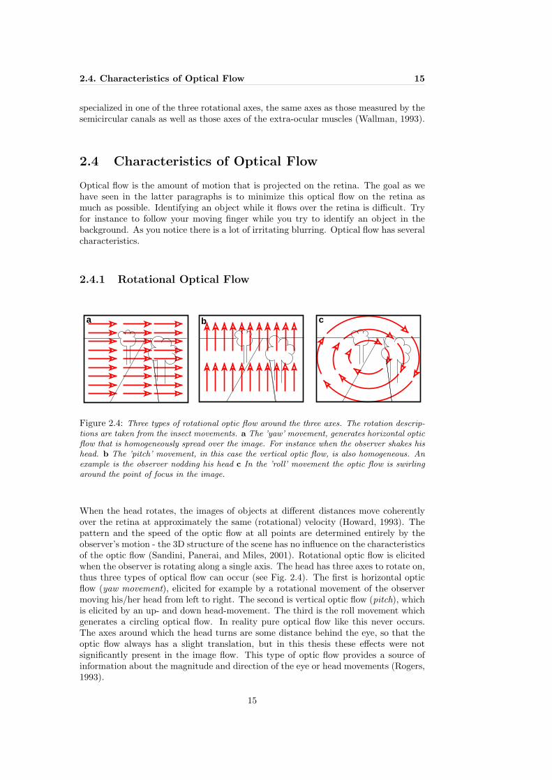
2.4 Characteristics of Optical Flow
Optical flow is the amount of motion that is projected on the retina. The goal as wehave seen in the latter paragraphs is to minimize this optical flow on the retina asmuch as possible. Identifying an object while it flows over the retina is difficult. Tryfor instance to follow your moving finger while you try to identify an object in thebackground. As you notice there is a lot of irritating blurring. Optical flow has severalcharacteristics.
2.4.1 Rotational Optical Flow
a b c
Figure 2.4: Three types of rotational optic flow around the three axes. The rotation descrip-tions are taken from the insect movements. a The ’yaw’ movement, generates horizontal opticflow that is homogeneously spread over the image. For instance when the observer shakes hishead. b The ’pitch’ movement, in this case the vertical optic flow, is also homogeneous. Anexample is the observer nodding his head c In the ’roll’ movement the optic flow is swirlingaround the point of focus in the image.
When the head rotates, the images of objects at different distances move coherentlyover the retina at approximately the same (rotational) velocity (Howard, 1993). Thepattern and the speed of the optic flow at all points are determined entirely by theobserver’s motion - the 3D structure of the scene has no influence on the characteristicsof the optic flow (Sandini, Panerai, and Miles, 2001). Rotational optic flow is elicitedwhen the observer is rotating along a single axis. The head has three axes to rotate on,thus three types of optical flow can occur (see Fig. 2.4). The first is horizontal opticflow (yaw movement), elicited for example by a rotational movement of the observermoving his/her head from left to right. The second is vertical optic flow (pitch), whichis elicited by an up- and down head-movement. The third is the roll movement whichgenerates a circling optical flow. In reality pure optical flow like this never occurs.The axes around which the head turns are some distance behind the eye, so that theoptic flow always has a slight translation, but in this thesis these effects were notsignificantly present in the image flow. This type of optic flow provides a source ofinformation about the magnitude and direction of the eye or head movements (Rogers,1993).
15

16 Chapter 2. How is a Stable Image realized in Biological Systems?
2.4.2 Translational Optical Flow
When the passive observer undergoes a pure translation, the optical flow has distinc-tively different characteristics. As shown in figure 2.5A the observer sees the opticflow emerging from its point of focus and speeding up as objects come nearer. In thiscase the 3D structure of the environment can be detected by this type of optical flow;nearby objects move faster on the retina. This phenomenon is called motion parallax(Sandini, Panerai, and Miles, 2001). If the observer is oriented side-ways the opticalflow is spread over the retina according to figure 2.5B. Also in this case, objects furtheroff move slower over the retina than objects closer by. Insects for instance use thisfeature to estimate the distance to an object (Srinivasan, 1993; Kootstra, 2002).
a b c
Figure 2.5: Translational optic flow, a The characteristics of the translational optic flow,experienced by the observer looking in the direction of the heading. b The optic flow experi-enced by a moving observer looking sideways, without making stabilizing movements. c Againthe moving observer is looking sideways, but this time the observer focuses on the telephoneplaced in the middle of the road. The scene now appears to pivot around this telephone.
Humans have a symmetrical OKR and we can stabilize images of objects at one dis-tance while ignoring distracting motion signals arising from objects at other distances,as we see in figure 2.5C.
2.5 What does Biological Information teach us inbuilding Artificial Intelligent Systems
”There is clearly something we can learn from biology, . . . , we’d be foolish toignore a billion years of evolution.” (Prof. Dr. Dorio) 2
Now that we know how a stable image is realized in biological systems, what does thisinformation tells us? One thing for sure, natural and artificial systems that share thesame environment may adopt similar solutions to cope with similar problems. There-fore biologists and engineers are often unintentionally focusing on the same topics, butfrom completely different points of view. The biologist analyzes behavior, while theengineer builds artificial systems with functionalities that fulfill certain desired behav-iors. Occasionally, these behaviors overlap in functionality. In this case a dialoguebetween the two fields would be fruitful. The challenge is to find a common groundfrom where the biologist and the engineer can take advantage of a direct interaction.
The biologist can inspire the engineer, but on the other hand the engineer is able togive the biologist a better understanding of his described biological model, by building
2Prof. Dr. Dorio at the university of Washington
16

2.5. What does Biological Information teach us 17
an artificial system according to the model. This approach is formally known as un-derstanding by building and is discussed on page 4. Multidisciplinary research groupswould be an ideal solution to stimulate the sharing of knowledge. The AI-lab in Zurichis an example.
Gaze stabilization is an example of common ground. The biological information dis-cussed in this chapter, has provided a detailed overview of the gaze stabilization mech-anism in natural organisms, in such a way that the engineer can create a formal modelapplicable for building an artificial system.
The biological information presented in this chapter gives us directly some ideas forbuilding a gaze stabilization system in an autonomous agent. Why would there betwo separate systems in biological systems to perform essentially the same image sta-bilizing task? The vestibulo-ocular reflex (VOR) is a very fast reflex with a latencyof 15-30 ms (Shibata and Schaal, 2001) that serves mainly to compensate for the veryfast head movements at frequencies in the range of approximately 1 to 7 Hz (Draper,1998). However, the VOR is less accurate at lower frequencies, especially those lowerthan 0.1 Hz where the gain drops significantly and a phase lead appears. Over therange of frequencies contained in normal head movements, the gain of the VOR is onlyabout 0.6 (Fuchs and Mustari, 1993).
The standard method in simulating a vestibular organ, is using a 3-axis gyroscope(Shibata and Schaal, 2001; Scassellati, 1998). The gyroscope is not sensitive to lowfrequency movements, in these two methods the optical flow is used to correct thisproblem. This project is planning to use slightly different hardware. To measure thetilt and roll, we want to use the ADX202E Dual-Axis Accelerometer with Duty CycleOutput. This hardware has been used for instance in autonomous flying machines(Stancliff, Laine, and Nechyba, 1994) to measure the tilt and roll. Their problem withthe ADXL202 was that it is very sensitive to engine vibrations.
When the accelerometers oriented so both its X and Y axes are parallel to the earth’ssurface it can be used as a two axis tilt sensor with a roll and a tilt axis. Once theoutput signal from the accelerometer has been converted to an acceleration that variesbetween -1 g and + 1 g, the output tilt in degrees is calculated as follows:
Tilt = arcsin (Ax/1g) (2.1)
Roll = arcsin (Ay/1g) (2.2)
The accelerometer uses the force of gravity as an input vector to determine orientationof an object in space. It is most sensitive to tilt when its sensitive axis is perpendicularto the force of gravity. At this orientation its sensitivity to changes in tilt is highest.When the accelerometer is oriented on axis to gravity, i.e., near its +1g or -1g reading,the change in output acceleration is negligible. When the accelerometer is perpendic-ular to gravity, its output will change nearly 17.5 mg per degree of tilt, but at 45o it ischanging only at 12.2 mg per degree and resolution declines. To measure the panningmovements, we are planning to use an angular velocity sensor with a Murata ceramicbimorph vibrating unit from Gyrostar.
17

18 Chapter 2. How is a Stable Image realized in Biological Systems?
2.6 Conclusion
Compared to the VOR, the optokinetic reflex (OKR) has the opposite characteristics.It takes time to process the visual information, therefore a latency occurs of 80-100 ms(Shibata and Schaal, 2001). But at low frequencies, i.e. less than 0.1 Hz, the OKR hasa gain of approximately 1.0 and no phase lead. From 0.1 Hz to 1.0 Hz the OKR losesgain and develops a phase lag due to its processing latency. Clearly, the vestibular andvisual reflexes are complementary. Therefore the combination of the two mechanismsallow for maximal image stabilization across all frequencies.
On the other hand, we also realize that the retinal slip is used as an error signal for thetuning of the VOR, therefore a reliable implementation of the OKR has priority numberone. In the next chapter we present an overview of some successful artificial gazestabilization systems. After that we develop a biologically plausible model to detectoptical flow, which will be tested in simulation and in a real-world office surrounding.
18

Chapter 3
Gaze stabilization in existingArtificial Systems
Many artificial eye/head systems are developed in which gaze stabilization has been an-alyzed, since this mechanism is a crucial feature to address in building visually guidedautonomous robots. Among other approaches in conventional vision- and robotic re-search, biological models have often been applied to artificial mechanical systems. Fol-lowing are some examples of successful implementations;
3.1 Shibata and Schaal
Shibata and Schaal developed a humanoid robot, able to stabilize its gaze by beingcapable of learning the accurate control of nonlinearities of the geometry of binocularvision as well as the possible nonlinearities of the oculomotor system. The controlcomponents in the oculo motor system resembled the known functional anatomy ofthe primate oculomotor system (Shibata and Schaal, 2001).
The optical flow was calculated by means of a block-matching method, i.e. the image is divided into a numberof square blocks. The best-matching block compared tothe template-image is found based on correlation by us-ing least-prediction error, with minimization of the mean-square difference. This implementation is not really ro-bust, except in the case of significant manual fine-tuningof the luminance differences and the image distortions.The learning system consisted of a biologically inspiredfeedback-error learning method combined with a non-parametric statistical learning network. By using eligi-bility traces, a concept from biology, and reinforcementlearning, they solved the problem of the unknown de-lays in the sensory feedback pathways, for example delayscaused by the complex visual information calculated. Shibata and Schaal (2001) actu-ally created an accurate mathematical control plant similar to the human optomotorsystem.
19

20 Chapter 3. Gaze stabilization in existing Artificial Systems
3.2 The Babybot Project
This project, performed at the LiraLab, the university of Genova, focuses on the devel-opment of learning and adaptive behavior (Metta, Panerai, and Sandini, 2000). Theacquisition of the appropriate behavior is obtained from an interplay with the agent’senvironment. The interaction of the agent’s adaptive structure and the dynamics ofits surrounding constrain the development of the otherwise difficult learning problem.The control structure of the robot evolves in stages therefore it constrains the learningprocess and potentially simplifies it. The agent is a physical robot interacting with theenvironment, i.e. the training set is collected on- line. Their interest is the develop-ment of the process of learning. The agent learns what it is capable of at that moment,constricted by the actual state of robot’s system (Panerai, Metta, and Sandini, 2000).E.g. the robot cannot move the neck without controlling the eyes first. The robotis equipped with module containing three rotational and three linear accelerometersmeasuring head movements, similar to the vestibular organ in humans, plus an activevision module measuring the optical flow (Metta, 2000). The integration of these twomodules results in a robust gaze stabilization system, that simulates the developmentalstages similar to the stages a newborn child passes.
3.3 Cog Project
The goal of the Cog project at the MIT Artificial Intelligence Laboratory is to createa human-like robot that closely mimics the sensory and sensori-motor capabilities ofthe human visual system (Scassellati, 1998;2001). This robot should be able to detectstimuli relevant to humans, and respond to these stimuli in a human-like manner. Cogis capable of performing the following human-like eye movements:
1. saccades: fast eye movement towards an interesting object
2. smooth pursuit: maintains a (slow) moving object of the fovea
3. vergence: adjusts the eyes for viewing object at varying depths
4. vestibulo-ocular reflex: stabilize the eyes while the head moves based on a gyro-scope
5. optokinetic reflex: stabilizes the eyes based on the retinal slip (image motion)
For the smooth pursuit eye movements, optical flow was measured as follows. A 7x7pixels central window, the center of the camera image, was appointed as the target im-age. In the successive frames this windows was correlated with a 44x44 pixels centralwindow. The 7x7 window was selected by an attention module based on three modulesthat searched in the image for motion, colorful objects and flesh-colored objects. Thebest correlation value gave the location of the target window in the new image, andthe distance from the center of the visual field gave the motion vector. This motionvector was scaled by a constant and used as a velocity command to the motors. Thisresembles the method used in the Shibata en Schaal humanoid project in which theycalled this eye movements the optokinetic reflex. In the Cog project, another modulecalculated the optical flow of the entire background, which also resulted in a motionvector. In this case the optical flow estimate was the displacement vector for the entirescene and not only for this small 7x7 object-tracking window, although it was calcu-lated in a similar manner.
20

3.4. The Kismet Project 21
Figure 3.1: The Humanoid Robot Kismet interacting with Cynthia Breazeal
The vestibulo-ocular reflex was constructed by integrating the velocity signals fromthree rate gyroscopes mounted on orthogonal axes. Because of the integration, thesystems tended to accumulate drift and the scaling constant to generate the appro-priate motor command had to be selected empirically. This problem was solved withadding the optokinetic reflex. The optokinetic reflex (OKR) was used to train thevestibulo-ocular reflex (VOR) scale constant and the accumulated drift was correctedbased on the optical slip.
3.4 The Kismet Project
We mention another a project at MIT, in this project social interaction with humanswas investigated. Based on the capabilities of Cog, this project made another steptowards a human-like robot. We mention this example to show that a humanoid robotequipped with a human-like gaze stabilization mechanism quickly gives humans theimpression of social intelligence (Breazeal, 1999). The robot platform Kismet, a move-able head with a human-like face, consisted of an attention system that integratedseparate perceptions, i.e. an auditory module, a motion detection module, a modulesensitive to bright colors (toys) and a module able to recognize faces in the image.The goal of this attention system was to make the robot interact with humans. Theinteresting detail of this research was that the robot was not aware of the fact that itwas communicating with humans, although it gave humans this feeling. Kismet wasable to display a large variety of facial expression combined with head postures. Inone experiment Kismet learned to react to people in an emotional way. By simplyanalyzing the change of the pitch in the human voice, the robot knew if he was praisedor punished. The robot reacted accordingly with the appropriate facial expression andhead posture. Its attention system also functioned in this experiment. The result wasthat the robot appeared to be socially intelligent (Breazeal, 1999). Another comparableapproach in this field by (Kuniyoshi et al., 2000) has investigated engineering solutionsfor biologically plausible models of visual processing of a humanoid robot for versatileinteraction with humans.
21

Chapter 4
A Biologically PlausibleModel to Detect ImageMotion
We now know the characteristics of optical flow. How is this information calculatedin biological systems? In the visual system of vertebrates on-off directionally selec-tive ganglion cells have been found (Ibbotson, 2001) These cells respond much betterto motion in one direction than to motion in the opposite direction. Aspects of thedetection of image motion for gaze stabilization appear to be calculated by directionallyselective ganglion cells (Amthor and Grzywacz, 1993). In this chapter we present thedevelopment of a motion detector based on the directionally selective ganglion cell, theelementary motion detector (EMD). The overall idea is to implement the optokineticreflex (OKR), i.e., to measure the amount of optical flow in the image of the robot dogin order to stabilize its gaze.
4.1 Processing of Optic Flow in Biological Systems
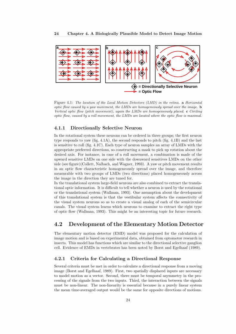
Directionally selective ganglion cells have been found in several vertebrates, althoughmonkeys and cats do not possess many of them. In cats only about two percent ofall ganglion cells are directionally selective (Amthor and Grzywacz, 1993). In rabbitsand squirrels this percentage is 20 to 25 percent. The same amount is also found inamphibians, birds, turtles and reptiles. The response properties in all these speciesand also within species differ in sensitivity to movement of light compared to darkobjects, preference for slow or fast speeds, and sensitivity to object shape.In insects similar receptors have been found. Collett, Nalbach, andWagner (1993) mention large-field neurons that sum the activitiesof many local motion detectors (LMDs), which give informationabout the direction of motion over a small area of the retina. Thesewide-neurons may be involved in decomposing optic flow (Collett,Nalbach, and Wagner, 1993). Two separate systems exist, one sys-tem sensitive to rotational flow and another system to translationalflow. These systems makes use of large-field neurons, but how neurons are used de-pends on the type of flow the system detects (Wallman, 1993).
23
24 Chapter 4. A Biologically Plausible Model to Detect Image Motion
b ca
= Directionally Selective Neuron= Optic Flow
Figure 4.1: The location of the Local Motion Detectors (LMD) in the retina. a Horizontaloptic flow caused by a yaw movement, the LMDs are homogeneously spread over the image. bVertical optic flow (pitch movement), again the LMDs are homogeneously placed. c Circlingoptic flow, caused by a roll movement, the LMDs are located where the optic flow is maximal.
4.1.1 Directionally Selective Neuron
In the rotational system these neurons can be ordered in three groups; the first neurontype responds to yaw (fig. 4.1A), the second responds to pitch (fig. 4.1B) and the lastis sensitive to roll (fig. 4.1C). Each type of neuron samples an array of LMDs with theappropriate preferred directions, so constructing a mask to pick up rotation about thedesired axis. For instance, in case of a roll movement, a combination is made of theupward sensitive LMDs on one side with the downward sensitives LMDs on the otherside (see figure)(Collett, Nalbach, and Wagner, 1993). A yaw or pitch movement resultsin an optic flow characteristic homogeneously spread over the image, and thereforemeasurable with two groups of LMDs (two directions) placed homogeneously acrossthe image in the direction they are tuned for.In the translational system large-field neurons are also combined to extract the transla-tional optic information. It is difficult to tell whether a neuron is used by the rotationalor the translational system (Wallman, 1993). One assumption about the developmentof this translational system is that the vestibular system affects the connectivity ofthe visual system neurons so as to create a visual analog of each of the semicircularcanals. The visual system learns which neurons to examine to extract the right typeof optic flow (Wallman, 1993). This might be an interesting topic for future research.
4.2 Development of the Elementary Motion Detector
The elementary motion detector (EMD) model was proposed for the calculation ofimage motion and is based on experimental data, obtained from optomotor research ininsects. This model has functions which are similar to the directional selective ganglioncell. Evidence of EMDs in vertebrates has been noted by Borst and Egelhaaf (1989).
4.2.1 Criteria for Calculating a Directional Response
Several criteria must be met in order to calculate a directional response from a movingimage (Borst and Egelhaaf, 1989). First, two spatially displaced inputs are necessaryto model motion as a vector. Second, there must be temporal asymmetry in the pro-cessing of the signals from the two inputs. Third, the interaction between the signalsmust be non-linear. The non-linearity is essential because in a purely linear systemthe mean time-averaged output would be the same for opposite directions of motions.
24

4.2. Development of the Elementary Motion Detector 25
According to these criteria, Reichardt developed the elementary motion detector (EMD)model in 1956, based on the optomotor response in insects (Reichardt, 1969). Thenon-linear factor in this model is multiplication, and the asymmetry is representedby delaying one input signal, which will be thoroughly treated in the next section.Several derivatives of his models have been developed based on his findings. Themotion-energy model by Adelson and Bergen (1985) and the Barlow-Levick Model byBarlow and Levick (1965) are two examples.
The EMD model has been implemented successfully in several robotic projects. Forexample, Viollet and Franceschini (1999) built an aerial minirobot which stabilizedin yaw by means of a visual feedback loop based on a single EMD. Iida (2000)(2001)successfully implemented a biologically inspired model of the bee’s visual “odometer”based on EMDs. The model was used to estimate the distance traveled based on theaccumulated amount of optic flow measured by EMDs. The model was implementedon an autonomous flying zeppelin robot, called Melissa. Kootstra (2002) also usingMelissa, created a landmark selection system based on EMDs. By using the charac-teristics of the translational optic flow, i.e. objects closer by move faster on the retina,relevant nearby landmarks for visual navigation were selected.
4.2.2 The Half-Detector
In 1956 Reichardt came up with his elementary motion detector (EMD) model. To givea clear picture of what this EMD is capable of, first we will introduce the half-detector(see Fig. 4.2). The half-detector is directionally selective, similar to the functionalityof the Local Motion Detector (section 4.1). After this section we will present the ele-mentary motion detector itself, which consists of two anti-symmetrical half-detectors,and thus able to detect optic flow in two directions.
The detector consists of two photoreceptors (P1 and P2). Each photoreceptor hasthree input values per pixel; red, green and blue. It gives as output the luminance,calculated as follows;
L = (R+G+B)/3.0 (4.1)
Furthermore, the half-detector has two high-pass filters (H1 and H2), a low-pass filter(L1) and a multiplication unit (M1). This half-detector extracts a motion signal fromthe spatiotemporal correlations that are present in the moving image in only onedirection (Reichardt, 1969). Let’s take a closer look at fig. 4.2.
High-pass Filter (H1 & H2)
H1(t) = P1(t)− P1(t− 1) (4.2)
The goal of the filter is edge-detection. The input signal P1(t) contains only luminanceinformation. As you can see in figure 4.2, the image that moves across the photore-ceptors, is first black, then white then black again. The filter only reacts to changesin luminance. P1(t) and P2(t) contain the luminance information that are received bytwo photoreceptors separated by distance S. By subtracting P1(t) from P1(t− 1) thisfilter only transmits the signal change.
Low-pass Filter (L1)
L1(t) = αH1(t) + (1.0− α)H1(t− 1) (4.3)
25

26 Chapter 4. A Biologically Plausible Model to Detect Image Motion
P
HH
L
M
1
1
1
2P
2
d
V0
1
t0 t1
����������������������������������������������������������������������
����������������������������������������������������������������������
�������������������������������������������������������
���������������������������������
���������������������������������
���������������������������������
������������������������������������������������������������������������������������������
������������������������������������������������������������������������������������������
Figure 4.2: Half-Detector, a one-directional motion detector. The half-detector perceivesluminance information from the image. The detector consists of two photoreceptors (P1 andP2), two high-pass filters (H1 and H2), one low-pass filter (L1) and a multiplication unit(M1). The photoreceptors are separated from one-another by distance d. The stimulus movesfrom left to right with velocity V0 across the photoreceptors. V0 is the velocity this half-detectoris tuned for. V0 depends on; 1. (t0 - t1), 2. how fast the perceived edge crosses d (the distancebetween the photoreceptors) and 3. α (the parameter of the low-pass filter). This figure showsa perfect match situation, the stimulus moves exactly as fast as the low-pass filter delays thesignal, and therefore the signals L1 and H2 cause M1 to give a high correlation signal (twopeaks = two matched edges). The full EMD contains an additional mirrored version of thehalf-detector, and the detector becomes bi-directionally sensitive
26

4.2. Development of the Elementary Motion Detector 27
0
0.1
0.2
0.3
0.4
0.5
0.6
0.7
0.8
0.9
1 2 3 4 5 6 7
Low
-Pas
s O
utpu
t
Time (seconds)
Low-Pass (alpha = 0.2)Low-Pass (alpha = 0.5)Low-Pass (alpha = 0.8)
Figure 4.3: The characteristics of the Low-Pass filter, in this figure α was varied. As youcan see the smaller the α the longer and smaller the response from the low-pass filter.
The low-pass filter is a time delay filter, the smaller the value of α the bigger the delay.The parameter α specifies the image speed this half-detector is tuned for. Actuallythe graph in figure 4.2 is incorrect, in this figure we used a real time delay. If you takea closer look at equation 4.3, you will see that the signal should slowly decay to zeroafter receiving an impulse. This decay is set by parameter α. According to eq. 4.3L1(t) is (1.0− α) times the previous value plus α times the signal delivered by P1(t).
Non-linear Filter (M1)
M1(t) = L1(t)H2(t) (4.4)
This filter compares two signals, in this case L1(t) and H2(t). Multiplying these signalsresults in a peak if the time-delay is exactly as long as it takes for the edge to movedistance d across the photoreceptors. Otherwise no match is found and M1(t) will notfire. We have now constructed a directionally selective motion detector, i.e. it reactsonly to stimuli in its “preferred direction” (see fig. 4.4) and does not give a responsefor motion stimuli in its “null-direction”.
4.2.3 The Elementary Motion Detector (Reichardt Detector)
An elementary motion detector (EMD) consists of two mirror-symmetrical half-detectors.The “preferred direction” in one half-detector is the “null-direction” and vice versa inthe other. The only addition is the subtraction unit. The response from the secondhalf-detector shows exactly the same response characteristics to motion in the oppositedirection as the half-detector in figure 4.2.
Role of the Subtraction Unit (S)
S(t) = M1(t)−M2(t) (4.5)
The signals from the two half-detectors have the same polarity, therefore the subtrac-tion unit is added to the model. M1(t) detects image motion from left to right, andM2(t) has the opposite preferred direction, thus the polarities of the two signals are
27

28 Chapter 4. A Biologically Plausible Model to Detect Image Motion
Figure 4.4: For motion in one direction (“the preferred direction”) the time-delay filtercompensates for the time-shift caused by the photoreceptor distance and the half-detector fires.For motion in the opposite direction (“the null-direction”) the time-delay causes that themultiplication unit finds no match at all. Note that in this figure t is an absolute time-delay.We use this type of delay to explain the functionality of the EMD. In our implementation weused a low-pass filter L1,2 in fig. 4.2
.
P
HH
L
M
1
1
P
2
M
L2
21
S
d
1 2
Figure 4.5: A full Elementary Motion Detector, consisting of two photoreceptors (P1 andP2), two high-pass filters (H1 and H2), two low-pass filters(L1 and L2), two multiplicationunits (M1 and M2) and a summation unit (S). This model is a bidirectional selective motiondetector.
also contrary. Otherwise it is not possible to distinguish the two opposite directionsof the optic flow across the photoreceptors. This results in a bidirectional selectivemotion detector.
if M1 < M2 ⇒ S < 0 Motion from left to rightif M1 > M2 ⇒ S > 0 Motion from right to left
28

4.3. Implementation of the Motion Detector 29
As a general reference to the EMD function of the two pixel luminances we will use:
En(t) = Γ(P1(t), P2(t)
)(4.6)
4.3 Implementation of the Motion Detector
We will now test the characteristics of the current motion detector model. We arelooking for a motion detector that gives a deterministic, linear reaction to the perceivedimage velocities. The ideal curve would be a linear curve that gives exactly the sameresponse for each bar width. Thus in the ideal case we demand a detector that is notdependent on the characteristics of the surroundings (in this case the bar-width) andonly depends on the amount of the image flow.
0
0.2
0.4
0.6
0.8
1
0 5 10 15 20 25 30
Ave
rage
EM
D o
utpu
t (A
ctiv
atio
n/ fr
ame)
�
Speed (pixels/ frame)
EMD 2 photocells with adjacent pixels
Single lineBar width(2 pix.)Bar-width(5 pix.)
Bar-width (20 pix.)
Figure 4.6: In this graph we present the performance of the elementary motion detector(EMD) with adjacent photoreceptors for four moving patterns. The results are obtained in asimulated environment in which for every experiment bars with different widths and differentspeeds moved across the EMDs on a black background. The y-axis displays the average EMD-output per frame, and the x-axis displays the speed in pixels per frame. Note that, based onthe average EMD output, no distinction between different image-flow velocities can be made,therefore this model is not good enough. We want to see a linear relation between EMD-outputand speed.
4.3.1 EMD Results in Simulation
The elementary motion detector is sensitive to image motion. In this section wepresent the characteristics of the EMD with adjacent photoreceptors in a simulated
29

30 Chapter 4. A Biologically Plausible Model to Detect Image Motion
environment. The simulation consists of a simple black image in which one hundredEMDs were placed homogeneously in the image. Across this black background a whitebar, with four different bar-widths (1, 2, 5 and 20 pixels) moves with an increased speedper cycle of the experiment. Speed is defined as the amount of pixels by which thebar-position is changed for every frame. In fig. 4.6 we plotted the outcome of thisexperiment. The y-axis displays the average EMD output per frame and the x-axisdisplays the speed of the respective white-bar per frame. The average EMD outputper frame is calculated by averaging the total EMD output sum of the hundred EMDsin the image examined per frame. As we can see in fig. 4.6 the EMD mostly reactsmaximally to image motion, and is therefore only sensitive to one particular value ofimage flow velocity, i.e. based on the average EMD output no distinction betweendifferent image flow speeds can be made. As we see, a standard EMD approach isable to detect the image flow velocity v0 it is tuned for. But it is not able to givea quantitative judgment of image flow velocity. Therefore, in the next section animproved version will be proposed.
4.3.2 Improvement of the Motion Detector
With the composition of the EMD, a motion detector is created that reacts maximallyto its optimal velocity v0. This velocity, v0, can be varied in two ways:
• Changing the distance d between the photoreceptors
• Changing the time-delay parameter α
Changing the time-delay parameter α has two disadvantages. First, if the parametersetting is specified for detecting slow image motion, a small α will result in a motiondetector tuned for a small v0 image velocity. But the slope of the decay causes thatthe low-pass filter to send a (decaying) signal (see fig. 4.3). This results in the factthat other faster edges will also react with the signal from the low-pass filter. There-fore you cannot be sure if the correlation found by the EMD results from the same edge.
= 0.5
= 0.2
= 0.8
v v+− 0v
EM
D o
utpu
t
Figure 4.7: This graph displays the dependency of the EMD sensitivity (v0) on the low-passparameter. The α-parameter tunes the sensitivity to the image velocity. The smaller the αthe more sensitive the EMD is to a wider range of image flow.
On the other hand, again in case of a small α other edges will enter this low-passfilter, before it empties itself after the first edge. Therefore the output-signal of thislow-pass filter will increase although the edges do not move faster. This will result ina higher response from the EMD. This means that the EMD becomes more and moredependent on the amount of edges, in other words dependent on the characteristics ofthe surroundings. An EMD detects if its v0 velocity is present in the image motion.
30

4.3. Implementation of the Motion Detector 31
But the accuracy depends on the parameter α. In case of a small α the EMD respondsto a large variety of image motion (see fig.4.7), but this is not what we are lookingfor, because in this case we lose detailed information about the exact amount of imageflow.
0
0.2
0.4
0.6
0.8
1
0 5 10 15 20 25 30 35
Ave
rage
EE
MD
out
put (
Act
ivat
ion/
fram
e)
Speed (pixels/ frame)
EMD 2 photocells with distance of 6 pixels
Single lineBar-width (2 pix.)Bar-width (5 pix.)
Bar-width (20 pix.)
Figure 4.8: In this graph we present the performance of the elementary motion detector(EMD) with a distance between its photoreceptors of five pixels for four moving bar-widths.The results are obtained in a simulated environment in which on a black background barswith different widths and different speeds per experiment moved across the EMDs. The y-axisdisplays the normalized average EMD-output per frame, and the x-axis displays the speed inpixels per frame. Note the distance of 5 pixels between the photoreceptors. This causes theEMD to show a maximum response for image velocity v0 = 6 pixels per frame. Thus byalternating the distance between the photoreceptors we can construct an EMD tuned for aparticular image speed v0. But still this is not good enough, the EMD does not react anymoreto small objects.
The final argument against changing the parameter α to create EMDs that are tunedfor different velocities is, that with changing α slower image motion becomes mea-surable, but in case of gaze stabilization motion detection also includes fast imagemotion. The frame-rate of our artificial system was fixed at 20 Hz. Detecting fasterimage motion is a prerequisite.
A single EMD is capable of detecting whether the image motion approximates thev0 velocity of the EMD. The goal of a gaze stabilization system is to adjust the eyevelocity to the image velocity, so that there is no more retinal slip. Therefore we need toconstruct a motion detector able to provide a quantitative signal of the image motion.As displayed in fig. 4.8 we see that changing the distance between the photoreceptorsresults in this altered EMD firing maximally at another velocity v0 compared to the
31

32 Chapter 4. A Biologically Plausible Model to Detect Image Motion
EMD with adjacent photoreceptors.
4.4 The Extended Elementary Motion Detector
The solution is simple, we present the extended elementary motion detector (EEMD).This EEMD consists of several EMDs each with a different distance d between itsphotoreceptors (Fig. 4.9). Therefore an EEMD is sensitive for several image-flowvelocities, each EMD is tuned for a different v0.
E1(t) = Γ(P3(t), P4(t)
)(4.7)
E2(t) = Γ(P2(t), P5(t)
)(4.8)
E3(t) = Γ(P1(t), P6(t)
)(4.9)
P P P P P P421 3 5 6
dd2
3
M A X
d1
E
E
E 3
2
1
Figure 4.9: Extended Elementary Motion Detector (EEMD). E1, E2, E3 are elementarymotion detectors (with the same low-pass parameter α). Each EMD has its own two photo-receptors with a different dn between its photoreceptors. Each EMD is therefore tuned for adifferent image motion v0. The weighted output of each EMD is analyzed by the MAX unit,in which a winner-takes-all principle prefers the EMD with the highest value and multipliesthis signal with dn, the distance between the photoreceptors of the particular ’winning’ EMD.
where the Γ-function stands for the EMD calculation (eq. 4.1 - 4.5), presented in equa-tion 4.6 .where En(t) is the bidirectional motion signal detected by the EMD En(t).Pn(t) are photoreceptors that receive luminance information.
32

4.4. The Extended Elementary Motion Detector 33
dmax = dargmax3n=1(En(t)) (4.10)
EEMD(t) = dmax3
maxn=1
(En(t)
)(4.11)
0
0.2
0.4
0.6
0.8
1
0 5 10 15 20
Ave
rage
EE
MD
out
put (
Act
ivat
ion/
fram
e)
Speed (pixels/ frame)
EMD 5 photocells (combi of 4 EMDs) with max-function, pixel-location: 0, 1, 3, 5, 7
Single lineBar-width (2 pixels)Bar-width (5 pixels)
Bar-width (20 pixels)
Figure 4.10: This graph represents the performance of the extended elementary motion de-tector (EEMD). The EEMD consists of 4 EMDs, with distances between the photoreceptors of1, 3, 5 and 7 pixels. The results are obtained in the same simulated environment as in fig. 4.6and 4.8. The y-axis displays the average EEMD-output per frame, and the x-axis displaysthe speed in pixels per frame. Note that the response to a single line clearly shows the fourEMDs with their own response multiplied by dmax from equation 4.10. This graph alreadycomes closer to the graph that we are looking for, because every curve contains an aspect of adeterministic relation.
4.4.1 EEMD Results in Simulation
By constructing the extended elementary motion detector (EEMD), we have createda detector able to detect four different image velocities. We have tested this EEMD inthe same simulated environment, i.e. a moving whitebar on a black background withbar widths ranging from one to twenty pixels, as used in testing the EMD character-istics. Speed is defined as the amount of pixels that the bar-position is changed everyframe. In graph 4.10 the characteristics of the EEMD output are plotted. The x-axisrepresents the speed of the respective white bar in every frame. The y-axis displays theaverage EEMD output. Again one hundred EEMDs are homogeneously placed acrossthe image and the total EEMD output was divided by the number of EEMD’s (onehundred). The curve of the “single line”-bar clearly displays the four separate EMD
33

34 Chapter 4. A Biologically Plausible Model to Detect Image Motion
responses multiplied by the distance between the corresponding photoreceptors. Thecurve of the bar with a width of two pixels results in a continuous version, becausethe low-pass filter value is not empty yet. The graph 4.10 does not show us exactlywhat we are looking for but the curve does show a deterministic response for everybar width, although not perfectly linear.
4.5 Discussion
As we see, the response for every bar-width quite different. The width of the white barinfluences the curvature. In a real-world implementation we do not expect difficultieswith this feature. Our assumption is that in a real-world environment all bar widths(or any other variations) are present simultaneously through a wide variety of object,colors etc. Therefore it is hypothesized that placing several EEMDs in a dispersedorder in the camera image and averaging the total EEMD output per time cycle willresult in a smooth deterministic graph of the detected image motion. In the nextchapter we will test the latter extended elementary motion detector (EEMD) in areal-world office environment and apply this model to obtain gaze stabilization in therobot dog.
34
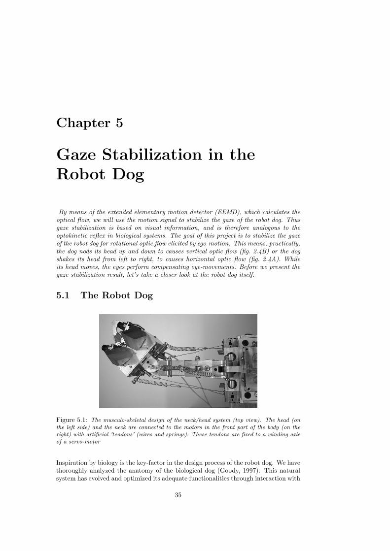
Chapter 5
Gaze Stabilization in theRobot Dog
By means of the extended elementary motion detector (EEMD), which calculates theoptical flow, we will use the motion signal to stabilize the gaze of the robot dog. Thusgaze stabilization is based on visual information, and is therefore analogous to theoptokinetic reflex in biological systems. The goal of this project is to stabilize the gazeof the robot dog for rotational optic flow elicited by ego-motion. This means, practically,the dog nods its head up and down to causes vertical optic flow (fig. 2.4B) or the dogshakes its head from left to right, to causes horizontal optic flow (fig. 2.4A). Whileits head moves, the eyes perform compensating eye-movements. Before we present thegaze stabilization result, let’s take a closer look at the robot dog itself.
5.1 The Robot Dog
Figure 5.1: The musculo-skeletal design of the neck/head system (top view). The head (onthe left side) and the neck are connected to the motors in the front part of the body (on theright) with artificial ’tendons’ (wires and springs). These tendons are fixed to a winding axleof a servo-motor
Inspiration by biology is the key-factor in the design process of the robot dog. We havethoroughly analyzed the anatomy of the biological dog (Goody, 1997). This naturalsystem has evolved and optimized its adequate functionalities through interaction with
35

36 Chapter 5. Gaze Stabilization in the Robot Dog
its environment. Therefore we carefully considered the physical properties of the robotdog, such as its sensors, actuators, materials and body-structure. Recent studies inembodied cognitive science show that an appropriate design of the morphology helpsthe learning process significantly in successfully fulfilling a certain task. In the designof the robot dog’s morphology we tried to imitate the physical properties of a naturaldog, i.e., the proportion and weight of the skeleton structure, the number and positionof the joints and the location of the actuators.
Figure 5.2: The control architecture of a pan-tilt active vision system. Motion detectorscover the entire image along both the horizontal and vertical axes. The outputs are spatiallyintegrated and averaged by the number of active EEMDs, and finally low-pass filtered. Thecorresponding motor outputs are determined by using function approximation based on theEEMD-output.
The skeleton of the robot is constructed out of alu-minium, and the dimension of the body is approximately750x600x300mm. The skeleton contains 28 passive joints,the rotational angles of each joint are mechanically re-stricted, and each joint is capable of a small translationaldisplacement as well. The passive joints are controlled by amuscle-like actuation method in which we incorporated elec-tric motors connected with a wire, and a spring in series.This artificial muscle mimics the properties of the muscle-tendon system of animals. Thus one motor can control mul-tiple passive joints. This approach has the advantage that
36

5.2. Experimental Results 37
joints are controllable in a non-linear fashion, while it closely mimics biological systems.
In the following section we focus only on the eye/head/neck part of the robot for thegaze stabilization task. The six muscles are installed in the frontal part of the bodywhich control eight passive degrees of freedom in the spinal block of the neck (fig. 5.1).In the skull of the robot a binocular active vision system is placed, which consists offour servo-motors (S3106 Futaba) and two miniature CMOS cameras. These servo-motors in the active vision system have a maximum angular speed of approximately 550deg/sec. The maximum rotational angles are restricted to 120 degrees in the horizontaldirection and 65 degrees vertically. All the motors are controlled by an external host-computer through communication with micro-controllers. Visual processing is alsoconducted at the same host-computer in which two frame-grabber devices are installed.
5.2 Experimental Results
0
0.2
0.4
0.6
0.8
1
0 20 40 60 80 100
Ave
rage
EE
MD
out
put
�
SpeedCommand[0-110]
EEMD output, delay 600.000
Motion/ nrActCells
Figure 5.3: This graph represents the EEMD output during a motor velocity gradually in-creasing from 0 to 110. We obtained this graph by sending commands ranging from 0-110to the motors while recording the EEMD-output. We repeated the experiment 100 times, andaveraged the outcome Additionally the standard deviation of the EEMD-output (±σ) is plottedas the dashed lines. The delay of 600.000, mentioned in the header of the graph, is the delaywith which commands were sent to the motor board to control the eye motors. This graphshows that the hypothesis assumed in chapter four is correct. The relation between speed andEEMD-output is now deterministic, and usable for gaze stabilization.
Concluding from figure 5.3 we clearly see that the extended elementary motion detector(EEMD) shows a beautiful deterministic response, which is usable for gaze stabiliza-tion. The hypothesis proposed in the previous chapter on page 4.5 is confirmed. This
37
38 Chapter 5. Gaze Stabilization in the Robot Dog
graph is obtained in a real-world office environment and shows that our assumptionthat the characteristics of this environment have a smoothing effect on the EEMD-output is correct.
In our experiments we implemented 3200 vertical and 3120 horizontal EEMDs. Thereason we used this number is that, while we performed the experiments in a real-officeenvironment, a lot of noise was present. The chance of a single EEMD giving an erro-neous output is quite high and averaging over several EEMDs minimizes this chance.The EEMDs cover 69x92 degrees in absolute angles, which is digitized into a 160x120pixel image. For the gaze control, the outputs of the EEMDs are spatially integratedinto mean vertical and a mean horizontal speeds, which are proportionally connectedto the eye servo-motors after low-pass filtering of the EEMD-output (fig. 5.2). Themotors are then controlled in such a way that apparent image motion induced byego-motion is canceled. Since the output of the proposed detector is highly non-linear(fig. 5.3), we need to find the correct mathematical function to translate the motionsignal to the appropriate motor command, so that it compensates for the perceivedamount of motion.
5.2.1 Function Fitting
In order to achieve live gaze stabilization, we have to find a function that matches theExtended Elementary Motion curve presented in figure 5.3. This graph is created bysending motor commands ranging from 0 to 110 to the eye motor, while the EEMDmodule measured the amount of motion. As we take notice of the graph, it shows anon-linear curve. On the other hand the characteristics of the motor are also non-linear, as we see in fig. B.2 in appendix B. In this graph we plotted the given motorcommand against the actual motor speed in degrees per second. What we are lookingfor, is the inverse curve of the EEMD plot (fig 5.3) Two methods were used: first,a mathematical approach in which the formal exponential curve was approximatedand second, a neural network approach, in which we let a neural network learn therelationship between the EEMD output and the corresponding motor command.
5.2.2 Exponential Curve Fitting
The main focus in programming the robot dog is minimizing the computational load,while the whole system operates real-time. Therefore speed-optimization is a veryrelevant aspect. We first tried a piece-wise linear approach, because it is simple andfast.The idea is as follows, we approximate the EEMD-curve with two linear equationsshown in figure 5.4. The appropriate values of a, b, c and d were deducted from theEEMD-curve. But we discovered that the EEMD-output curve was non-linear andtherefore this piece-wise linear approach was not good enough.
Examining figure 5.3, we notice that the form of the EEMD-curve shows the typicalform of an exponential function.
f(x) = a ∗ eb(x−c) + d (5.1)
38

5.2. Experimental Results 39
f(x)
g(x)
Figure 5.4: This graph presents the form of the two linear curves that are used to approximatethe EEMD-output function (for details, see text)
By using a mathematical approach we can construct an exact replication of the EEMDcurve as follows:
a Maximum value of the EEMD-output
b Roundness of the exponential curve
c Maximum speed measurable by EEMD
d Vertical shifting of the graph, the minimum EEMD value
Parameters a and c were deduced manually from the graph in fig 5.3. Parameter brepresents the roundness of the exponential curve, calculated as follows:
f(x) = y = a ∗ eb(x−c) + d (5.2)
(y
a− d) = eb(x−c) (5.3)
ln(y
a− d) = b(x− c) (5.4)
b =ln( ya − d)(x− c)
(5.5)
We acquire the correct value for b by filling in the EEMD-value that is elicited with amotor command of 60 to approximate the roundness of the exponential function. Inthe implementation we used the inverse-function of the exponential curve:
speed =(ln( (EEMD
a − d) + bc)b
(5.6)
Results Exponential Curve-Fitting Method
To test the performance of this approach, we let the motor swing from left to rightwith different motor commands and we let the function approximation module esti-mate what motor command was given to the motor based on the visual signal resultingfrom the EEMD module. The idea behind it is, if we can estimate the given motorcommand based on the measured image flow, we can also generate the same motorcommand, which will result in stabilizing behavior.
39
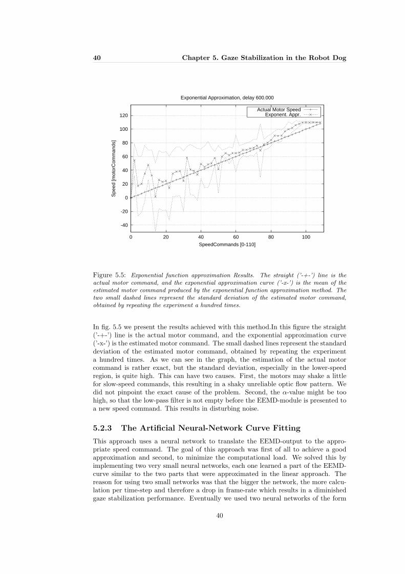
40 Chapter 5. Gaze Stabilization in the Robot Dog
-40
-20
0
20
40
60
80
100
120
0 20 40 60 80 100
Spe
ed [m
otor
Com
man
ds]
SpeedCommands [0-110]
Exponential Approximation, delay 600.000
Actual Motor SpeedExponent. Appr.
Figure 5.5: Exponential function approximation Results. The straight (’-+-’) line is theactual motor command, and the exponential approximation curve (’-x-’) is the mean of theestimated motor command produced by the exponential function approximation method. Thetwo small dashed lines represent the standard deviation of the estimated motor command,obtained by repeating the experiment a hundred times.
In fig. 5.5 we present the results achieved with this method.In this figure the straight(’-+-’) line is the actual motor command, and the exponential approximation curve(’-x-’) is the estimated motor command. The small dashed lines represent the standarddeviation of the estimated motor command, obtained by repeating the experimenta hundred times. As we can see in the graph, the estimation of the actual motorcommand is rather exact, but the standard deviation, especially in the lower-speedregion, is quite high. This can have two causes. First, the motors may shake a littlefor slow-speed commands, this resulting in a shaky unreliable optic flow pattern. Wedid not pinpoint the exact cause of the problem. Second, the α-value might be toohigh, so that the low-pass filter is not empty before the EEMD-module is presented toa new speed command. This results in disturbing noise.
5.2.3 The Artificial Neural-Network Curve Fitting
This approach uses a neural network to translate the EEMD-output to the appro-priate speed command. The goal of this approach was first of all to achieve a goodapproximation and second, to minimize the computational load. We solved this byimplementing two very small neural networks, each one learned a part of the EEMD-curve similar to the two parts that were approximated in the linear approach. Thereason for using two small networks was that the bigger the network, the more calcu-lation per time-step and therefore a drop in frame-rate which results in a diminishedgaze stabilization performance. Eventually we used two neural networks of the form
40

5.2. Experimental Results 41
presented in fig. 5.6, which we trained with the back-propagation algorithm (Haykin,1999).
Figure 5.6: The neural network used in the function approximation, it represents the simplestnetwork possible, containing one input neuron, two hidden neuron and a single output neuron.
5.2.4 Summary of the Back-Propagation Algorithm
The training method used for training the two small neural networks is according tothe back-propagation rules.
Initialization
The weights and thresholds are initialized according to a uniform distribution whosemean is zero and whose variance is chosen in such a way that the standard deviationof the weighted sum of all synaptic inputs plus the bias lies in the transition betweenthe linear and saturated parts of the sigmoid activation function
Presentation of the Training Examples
We present the network with an epoch of training examples. For each example in theset, ordered in a random order, the sequence of forward and backward computation,described in the following points were performed.
Forward Computation
A training example is denoted by [x(n), d(n)], with x(n) as the EEMD-output appliedto the input-layer and desired response d(n), the stabilizing speed command. Theactivity v(l)
j for neuron j in layer l is:
v(l)j (n) =
m0∑i=0
w(l)ji (n)y(l−1)
i (n) (5.7)
where y(l−1)i (n) is the output (function) signal of neuron i in the previous layer l - 1
at iteration n and w(l)ji (n) is the synaptic weight of neuron j in layer l that is fed from
neuron i in layer l -1. For i = 0, we have y(l−1)0 (n) = +1 and w
(l)j0 (n) = b
(l)j (n) is the
bias applied to neuron j in layer l. The output signal of neuron j in layer l is:
y(l)j = φj(vj(n)) (5.8)
where φ(x) represents a sigmoid-function. If neuron j is in the first layer (i.e., l = 1);
y(0)j (n) = xj(n) (5.9)
41

42 Chapter 5. Gaze Stabilization in the Robot Dog
where xj(n) is the jth element of the input vector x(n). If neuron j is in the output-layer(i.e., l = L, where L is the depth of the network)
y(l)j = oj(n) (5.10)
where oj(n) represents the network output. The error signal is computed:
ej(n) = dj(n)− oj(n) (5.11)
where dj(n) is the jth element of the desired response vector d(n).
Backward Computation
The computation of the local gradients of the network is defined by:
δ(l)j (n) =
[e
(L)j (n)φ
′
j(v(L)j (n)) for neuron j in out-layer L
φ′
j(v(l)j (n)
∑k δ
(l+1)k (n)w(l+1)
kj (n) for neuron j in hid-layer l(5.12)
where the prime in φ′
j(·) denotes differentiation with respect to the argument. Adjustthe synaptic weights of the network in layer l according to the generalized delta rule:
w(l)ji (n+ 1) = w
(l)ji (n) + α[w(l)
ji (n− 1)] + ηδ(l)j (n)y(l−1)
i (n) (5.13)
where η is the learning-rate parameter and α is the momentum constant.
Iteration
The forward and backward computation are repeated by presenting new epochs oftraining examples to the network until the stopping criteria is met; the absolute rateof change in averaged square error per epoch is smaller that 1.0 %
E2av =
1N
N∑n=1
(dj − oj)2 (5.14)
where E2av represents the averaged square error energy.
5.2.5 Results of the Neural-Network Curve-Fitting Method
Figure 5.7 presents the results achieved with the curve fitting network based on aneural network method. The two small networks are trained according to the rulesexplained the latter section. The method was tested in the way the exponential curvefitting method was tested. The motor was swung from left to right with differentspeeds, while our system estimated the given motor command. In fig. 5.7 the straightline (’-+-’) is the actual motor command, and the ’-x-’-line represents the mean outputof the neural network curve fitting method. The experiment was repeated 100 timesin order to get a good impression of the performance of the system. The small dashedline is the ± standard deviation of this signal. As shown in the graph, the estimationof the given motor command is good. Another thing we can deduct from the graph iswhether noise is present in the lower speed regions.
42

5.2. Experimental Results 43
-40
-20
0
20
40
60
80
100
120
0 20 40 60 80 100
Spe
ed [m
otor
Com
man
ds]
SpeedCommand [0-110]
Neural Approximation, delay 600.000
Actual Motor SpeedNeural Appr.
Figure 5.7: The Neural Network function approximation results. The straight (’-+-’) line isthe actual motor command, the ’-x-’ line is produced by the neural network function approxi-mation approach. The two dashed lines represent the standard deviation (±σ) As we see, thisapproach is able to estimate the given motor command, although the σ shows the presence ofnoise in the system. Note the noise in the lower speed region.
5.2.6 Comparing the Results
To compare the two curve fitting methods, the root mean square (RMS) is applied.The RMS-error has the same scaling as the curves have in fig. 5.7.
Erms =√E2av (5.15)
Comparing figure 5.7 with figure 5.5, we see many resemblances. But in table 5.1 theRMS error (equation 5.14) shows that the neural network approach is better than theexponential method, although this is only a minimal difference. The computationalload for instance is also approximately equal. This data is obtained by calculating theRMS error of the estimated motor command, estimated by one of the two curve fittingmethods, minus the actual given motor command (see graph 5.7 and 5.5).
Curve Fitting Method ErmsExponential 12.85Neural network 11.13
Table 5.1: This table shows the average square error of the exponential and the neural networkcurve fitting. This data-comparison shows that the neural network method is slightly betterthan the exponential curve fitting method.
The reason we also implemented the neural network method is that in the future this
43

44 Chapter 5. Gaze Stabilization in the Robot Dog
learning method is to be used for adjusting the network online. This is necessary tocope with sudden changes in the environment (indoor/outdoor light intensities) andit will result in a robust performance. Also, this method does not rely on manuallydetermined parameters and is therefore easier to rehearse.
5.3 Gaze Stabilization Results
The neural network approach and the exponential approach show rather good approx-imation results as shown in the latter sections. In this section we present the gazestabilization results based on the exponential and the neural-network approach in therobot dog. To test our system we moved the head of the robot from left to right.One camera of the robot head was fixed to its head, while the other was performingstabilizing movements in order to keep the image in the camera stationary. We trackedthe same small object in both camera images, the absolute pixel-location of this objectwas plotted in figure 5.8. 1
-60
-40
-20
0
20
40
0 1 2 3 4 5 6
Hor
izon
tal O
rient
atio
n [p
ixel
s]
�
Time [seconds]
Performance of Stabilization with BackProp Curve Fitting Method
Orientation of Gaze stabilized EyeOrientation of Fixed Eye
Figure 5.8: Gaze stabilization results based on the back-propagation trained neural network,that learned what EEMD-output corresponded to motor command, in order to sent stabilizingcommands to the motors. The ’-+-’ line represents the view-direction of the stabilizing eye.The ’-x-’line is created by the eye fixed to the head, and therefore shows the trajectory of thehead itself. The gaze stabilizing eye performs stabilizing movements (see text for details).
We conducted a performance test of the proposed gaze stabilization method, in whicha simple neck/head behavior was programmed by using 6 motors. The target behaviorof neck/head system was prepared, i.e. the swing motions between right and left. Theactuation of the neck/head motors was not sensory motor coordinated, but simplysupplied constant energy (constant duty ratio), and changed the direction after a cer-
1Movies of the gaze stabilization behavior can be acquired by sending an email to [email protected]
44

5.4. Discussion 45
tain period of time. One of the camera systems is simply fixed on the head, and isused to analyze the motion of the head in later stage, whereas the other camera sys-tem stabilizes the gaze by using the model described in the previous section (Fig. 4.2).After the experiments, the performance is evaluated by motion of the stored image, inwhich a fixed reference point in the environment was tracked. This information pro-vides angular displacement of the image during the computational time steps, whichcorresponds to the ego-motion of cameras. Namely, while the neck/head system inaction, if the trajectories of this reference point in the image stays at a point, gazestabilization is successful. The experiments were conducted in an uncontrolled officeenvironment. The sample snapshot from the robot perspective is shown in figure 5.9,captured by the active vision system. The frame-rate of the image processing is fixedto 20 frames per second.
Figure 5.82 illustrates two trajectories, one from the fixed camera and the other fromthe camera with gaze stabilization based on the back-propagation curve fitting method.The values in the vertical axis indicate the angular distance of the external referencepoint with respect to the camera image. Therefore the angular velocity of the ego-motion can be obtained by the corresponding derivatives in this figure.
5.4 Discussion
Due to the non-linear dynamics of the musculo-skeletal structure, the motion of thehead shows relatively complex behavior, which make gaze stabilization very difficult.One explanation of the sub-optimal gaze stabilization results is that the elasticity ofthe spring factor in the muscles produces a totally non-linear force, irrespective ofthe neck-motors constant velocity. Another explanation is that because of the lack ofaccuracy of the lower speed region of the function approximation, this module doesnot always generates the proper velocity command. In this gaze stabilization process,this gives rise to an incorrect compensating movement. The implication of this fault isthat visually-based gaze stabilization generates its “own” image flow, while it is com-pensating for another source of ego-motion. The system sometimes reacts to motionelicited by itself.
Figure 5.9: A snapshot of the uncontrolled office environment, which is used in the experi-ment. The image is captured by the active vision system.
In the gaze stabilization experiment higher optical flow velocities do occur. Althoughthe extended model of motion detection enhances the range of the optical flow velocitycompared to the single EMD, it does not result in perfect gaze stabilization behavior.
2Appendix C contains the gaze stabilization graph based on the exponential curve fitting method
45

46 Chapter 5. Gaze Stabilization in the Robot Dog
An obvious solution to increase the performance of the robot dog appears to be theaddition of another EMD in the extended elementary motion detector. This additionalEMD would have a bigger distance between its photoreceptors, which would result ina detector able to measure higher optical flow values. But the motion detector is ableto measure optical flow up to a maximum of 70 deg/s, which corresponds to a motorcommand of 120. As we see in appendix B, the real motor speed increases non-linearas the motor command increases. In the higher speed command region, we lack ex-pression power to correct the high speed optical flow exactly, therefore we did notgenerated speed command higher than 110. This value was manually determined.
In biological systems as well as in the robot dog, it takes time to process the visual in-formation which causes a latency to occur. This is the reason for the performance of theoptokinetic reflex to decrease as the image speed increases. The system should reactfaster in this situation, but the visual processing speed (CPU-speed) is a bottle-neck.This conflict is also present in the robot dog: The frame-rate of the frame-grabberhad to be limited to a fixed 20 Hz. Which means that very fast image motion (aboveapproximately 70 deg/s) will appear as a blur and thus the robot is not able to copewith such fast motion. The solution to this problem would be to increase the frame-rate of the frame-grabber and the CPU-speed of the visual processor. The maximalperceivable image flow velocity does not depend on the detector but depends more onthe frame-rate of the frame-grabber. With an increasing frame-rate, the EEMD canbe modified to detect higher velocities.
An argument against this enhancement is how fast this optokinetic reflex actuallyshould be. As mentioned earlier (section 2.6), since the vestibulo-ocular reflex in na-ture considerably contributes to stabilize the gaze during the high speed head move-ments, visually-based gaze stabilization might not need to cope with these high speedimage velocities. In the natural habitat of the dog image flow up to 70 deg/s occurs forinstance as the dog walks or nods its head. Higher image flow velocities occur whenthe dog is running and especially when the dog jumps. The additional enhancementthis system needs is an implementation of the vestibulo-ocular reflex. This reflex isable to detect head velocities, much greater than our recent implementation of theoptokinetic reflex. Therefore we can say that our implementation of the optokineticreflex is successful. We have created a motion detector able to measure optical flow ina deterministic manner, and we used this detector to stabilize the gaze of the robot dog.
Compared to other existing artificial intelligence projects mentioned in chapter threethis project differs from those projects on several aspects. First, this is not a hu-manoid project, but a canine project. Second, the robot dog project has its focuson locomotion, while the other artificial projects work with a stationary robot torso.These projects do not include topics like locomotion. Third, the gaze stabilizationapproach used in the robot dog project is characterized by biological plausibility andthe goal is to built a fully plausible mimicked mechanism of the canine’s stabilizationmechanism, starting with the optokinetic reflex. The four existing projects have im-plemented an analogous version of the optokinetic reflex based on a non biologicallyinspired mathematical correlation method to calculate image motion.
46

Chapter 6
Conclusion
Visual perception of the surrounding world is an important source of information forthe survivability of an animal. The problem in using this source is that motion, eitherelicited by the surroundings or by the animal itself, disturbs the source. The task ofthe visual system is to cope with wildly moving projections of the surroundings onthe animals retina. When the disturbances are caused by ego-motion, this process iscalled gaze stabilization. Gaze stabilization has the goal of keeping the image, whichis projected on the retina, stationary while the animal itself disturbs the projection bylocomotion. Good examples of robust autonomous systems are found in nature. Theirefficient way of problem solving can be used in the creation of robust artificial systems.At the AI-lab in Zurich the philosophy is to strive for a good comprehension of the in-ternal mechanism that produces this robust behavior, a methodology characterized asunderstanding by building. This project was initially inspired by the efficient locomo-tion of the biological dog. The project’s goal is to understand the perceptive processeswhich are the consequences of the physical structure of the dog. Therefore in design-ing the robot dog, we mimicked the dog’s physical properties. The first task, achievinglocomotion, is directly coupled to my graduation project: “Biologically inspired gazestabilization” in which I examined the coupling of the eye motors to provide a stableview while the robot is walking.
What are the mechanisms behind gaze stabilization during ego-movements?
In biological systems gaze stabilization is achieved by the cooperation of several re-flexes:1. The optokinetic reflex (OKR), which relies on visual information, i.e., translationaland rotational optic flow, measured in the entire retina. The aim of the OKR is tokeep the image still on the fovea. The OKR functions as a visually-driven closed-loopnegative feedback tracking system.2. The vestibulo-ocular reflex (VOR), which relies on signals produced by the vestibu-lar organ in the middle ear. This organ determines the absolute movement of the headin three dimensional space, i.e., three linear- and three rotational movements.3. Three supporting reflexes; vestibulo-collicular reflex, opto-collicular reflex and thecervico-ocular reflex.
Insects stabilize their gaze, while flying and turning, by moving their head faster thatthe thorax. Hereby is the time-span of the head-saccade minimized. Thus the sta-tionary and stable view is maximized. In birds a similar approach can be observed, awalking pigeon bobs with its head making fast head-saccades to reduce the interruption
47

48 Chapter 6. Conclusion
of stable gaze. This phenomenon is called saccade because of the resemblance betweenthe jump-like eye-movements which are called saccades. Generating a conflict betweenthe vestibular and the visual signals by positioning the bird on a stationary perchsurrounded by an oscillating environment results in the behavior that the head movesalong with the surroundings. This shows the visual predominance in the gaze sta-bilization process. Chameleons scan their environment with saccadic eye movementsthat are independent in the two eyes. Once the prey is located, the head is aligned andthe two eyes converge to fixate the target binocularly. The chameleon’s gaze stabiliza-tion behavior is characterized by fast eye-saccades, while its head, if needed, makessmooth pursuit movements. The interesting detail of the rabbit is that it lacks a fovea,which means that this animal provides the opportunity to study gaze stabilization ina strictly isolated form. In humans reflex-based gaze movements are often performedusing eyes only. Humans have a frontal eye position, therefore information about dis-tances of objects can accurately be obtained.
The goal of gaze stabilization is to minimize two types of optical flow on the retina.The first is rotational optical flow, which is elicited when the observer rotates alongone of its three axes. The second is translational optical flow, which occurs when apassive observer undergoes a pure translational movement. Now that we know how astable image is realized in biological systems, what does this information tells us inbuilding artificial systems? Well, biological and artificial systems that share the sameenvironment may adapt similar solutions to cope with similar problems.
How can these mechanisms be realized in artificial systems?
Gaze stabilization has the goal to minimize retinal slip. The vestibulo-ocular reflex(VOR) can be implemented using a gyroscopic device, which simulates the function-alities of the vestibular organ. In this project we first focus on the optokinetic reflex(OKR), as a first step toward a fully-integrated gaze stabilization model. Other exist-ing artificial system projects, also inspired by biological solutions, also integrated thetwo reflexes to build a robust gaze stabilization system.
To calculate the optical flow in the image, we used a biologically plausible model, thathas been developed by Reichardt based on the directionally selective ganglion cellsfound in insects and several vertebrates. This model is named the ’elementary motiondetector’ (EMD). The EMD consists of two photoreceptors, low-pass filters, multipli-cation and a subtraction. The motion signal is calculated as follows. Two spatiallyadjacent photoreceptors receive luminance information. These signals are delayed bya temporal low-pass filter, a good approximation that biology also appears to use. Thedelayed channels are then correlated with adjacent non-delayed channels by means ofa multiplication operation. Finally, the output of two anti-symmetrical half-detectors,each sensitive for motion in one direction, are subtracted to obtain a directional mo-tion response.
In our implementation of the EMD we extended this model. Instead of using onlytwo adjacent photoreceptors, we added pairs of photoreceptors with a wider distance.The maximum activation of the outputs of the extended elementary motion detector(EEMD) are selected as output. Compared to the original models, the EEMD providesa wider range of motion velocity measurement. The motion signal produced by theEEMD is used to stabilize the gaze of the robot dog. Thus gaze stabilization based onvisual information, and is therefore analogous to the optokinetic reflex.
48

49
The design of the robot dog mimics the physical properties of the anatomy of thebiological dog. In this project we mainly used the neck/head/eye-system. Six muscles(wires and springs) are installed in the frontal part of the dog, which control eightpassive degrees of freedom in the spinal blocks. A binocular active vision system isplaced in the skull of the robot. EEMDs cover the entire image along both horizontaland vertical axes. The outputs are spatially integrated, averaged and low-pass filtered.The corresponding motor command to generate the appropriate stabilizing behavioris calculated using two different types of curve fitting methods. First a mathemat-ical approach, which uses the exponential form of the EEMD-curve to calculate themotor command and second an artificial neural-network approach, in which a back-propagation learning method adjusts the weights of two small neural networks. Theaverage square error of the neural network method was lower, and thus this methodis considered better. This method was used in successfully stabilizing the gaze of therobot dog. While the motion detector is able to measure optical flow up to 70 deg/s,the system cannot respond to optical flow of a higher order, because of image blur.This maximal image flow velocity can be increased by increasing the frame-rate ofthe frame-grabber. It seems reasonable to assume, that similar limitations exist inthe biological gaze stabilization, necessitating an additional sensing signal apart fromvision. In many species this signal is delivered by the vestibular organ. This organmeasures head velocities higher than measurable by method based on optical flow. Toobtain a perfect gaze stabilization performance the robot dog needs to be equippedwith the optokinetic reflex and with a device with the functionality of the vestibularorgan.
How does the proposed gaze stabilization help higher cognitive tasks suchas object recognition?
In this thesis we have discussed the need for a gaze stabilizing mechanism; The prob-lem of relying on visual sensor information is that motion, caused by ego-motion, suchas walking or running, disturbs this sensor. Consequently, a robot that walks or runsdefinitely needs to stabilize its gaze before it is able to do tasks such as object recog-nition. Although gaze can be stabilized, a visual perception system, will always haveto deal with residual optical flow. This flow is in many cases not a nuisance, buta means to solve, e.g., 3D object-perception. Thus the extended elementary motiondetector (EEMD), developed in this project, can also deliberately use image flow todetect objects.
A future topic might be object-tracking based on motion in a local area of image.Preliminary experiments with the robot dog show that just a small modification of theactual system, enables object-tracking with a stationary background. More sophisti-cated techniques with a non-stationary (counter-moving) background is definitely aninteresting feature to explore.
49


References
Adelson, E.H. and J.R. Bergen. (1985). Spatiotemporal energy models for the per-ception of motion. J. Opt. Soc. Am., 2:284–299.
Amthor, F. and N.M. Grzywacz. (1993). Directional selectivity invertebrate retinalganglion cells. In F.A. Miles and J. Wallman, editors, Visual Motion and Its Role inthe Stabilization of Gaze, volume 5. Elsevier Science Publishers B.V., pages 79–100.
Barlow, H.B. and W.R. Levick. (1965). The mechanism of directionally selective unitsin the rabbit’s retina. J. Physiol., 178:477–504.
Borst, A. and M. Egelhaaf. (1989). Principles of visual motion detection. TrendsNeurosci, 12:297–306.
Borst, A. and M. Egelhaaf. (1993). Detecting visual motion: Theory and models. InF.A. Miles and J. Wallman, editors, Visual Motion and Its Role in the Stabilization ofGaze, volume 5. Elsevier Science Publishers B.V., pages 3–27.
Breazeal, C. (1999). Imitation as social exchange between humans and robots. InProceedings of the 1999 Symposium on Imitation in Animals and Artifacts (AISB99),pages 96–104. Edinburg, Scotland.
Bruce, Vicki, Patrick R. Green, and Mark A. Georgeson. (1996). Visual Perception,Physiology, Psychology, and Ecology. 3rd edition. 27 Church Road, Hove, East Sussex,BNA 2FA, UK: Psychology Press, Bookcraft Ltd., Bath, United Kingdom. ISBN 0-86377-451-2(Pbk).
Burdess, C. (1996). The vestibulo-ocular reflex: computation in the cerebellar floccu-lus. Ph.D. thesis, University of Edinburgh.
Collett, T.S., H-O. Nalbach, and H. Wagner. (1993). Visual stabilization in arthro-pods. In F.A. Miles and J. Wallman, editors, Visual Motion and Its Role in theStabilization of Gaze, volume 5. Elsevier Science Publishers B.V., pages 239–264.
Collewijn, H. (1977). Eye and head movements in freely moving rabbits. Journal ofPhysiology, (266):471–498.
Draper, Mark. (1998). The adaptive effects of virtual interfaces: Vestibulo-ocularreflex and simulator sickness.
Friedman, M.B. (1975). Visual control of head movements during avian locomotion.In Nature. London, pages 67–69.
Fuchs, A.F. and M.J. Mustari. (1993). The optokinetic response in primates and itspossible neuronal substrate. In F.A. Miles and J. Wallman, editors, Visual Motionand Its Role in the Stabilization of Gaze, volume 5. Elsevier Science Publishers B.V.,pages 343–370.
51

52 References
Gioanni, H., M. Bennis, and A. Sansonetti. (1993). Visual and vestibular reflexesthat stabilize gaze in the chameleon. Visual Neuroscience, 10:947–956. CambridgeUniversity Press.
Goody, P.C. (1997). Dog Anatomy: A Pictorial Approach to Canine Structure. J.A.,Allen & Co. Ltd.
Gullan, P.J. and P.S. Cranston. (2000). The insects, an Outline of Entomology.Second edition. Chapman and Hall.
Hateren, J.H. van. (1992). Theoretical predictions of spatio-temporal receptive fieldsof fly lmcs, and experimental validation. J.Comp.Physiol, (155):157–170.
Haykin, S. (1999). Neural Networks, a comprehensive foundation. Second edition.Robbins, T.
Hengstenberg, R. (1993). Multisensory control in insect oculomotor systems. In F.A.Miles and J. Wallman, editors, Visual Motion and Its Role in the Stabilization of Gaze,volume 5. Elsevier Science Publishers B.V., pages 285–298.
Howard, I.F. (1993). The stability of the visual world. In F.A. Miles and J. Wallman,editors, Visual Motion and Its Role in the Stabilization of Gaze, volume 5. ElsevierScience Publishers B.V., pages 103–118.
Ibbotson, Michael. (2001). identification of mechanisms underlying motion detec-tion in mammals. In J.M. Zanker and J. Zeil, editors, Motion vision, computa-tional,neural,an ecological constraints. Springer Verlag, Berlin, Heidelberg, New York.
Iida, F. (2001). Goal-directed navigation of an autonomous flying robot using biologi-cally inspired cheap vision. In Proceedings of the 32nd ISR (International Symposiumon Robotics), pages 1404–1409, 19-21 April.
Iida, F. and D. Lambrinos. (2000). Navigation in an autonomous flying robot by usinga biologically inspired visual odometer. In Sensor Fusion and Decentralized Control inRobotic System III, volume 4196, pages 86–97. Proceeding of SPIE, Photonics East.
Kootstra, G.W. (2002). Selection of landmarks for visual navigation. Master’s thesis,University of Groningen.
Kuniyoshi, Y., S. Rougeaux, O. Stasse, G. Cheng, and A. Nagakubo. (2000). Ahumanoid vision system from versatile interaction. In BMCV 2000, LNCS 1811, pages512–526. S.W. Lee, H.H. Buelthoff, T. Poggio (Eds.).
Lichtensteiger, Lukas and Peter Eggenberger. (1999). Evolving the morphology of acompound eye on a robot. In proceedings of the third european workshop on advancedmobile robot, pages 127–134. eurobot ’99, IEEE.
McCollum, G. and R. Boyle. (2001). Conditional transitions in gaze dynamics roleof vestibular nuclei in eye-only and eye/head gaze behaviors. Biological Cybernetics,85:423–436.
Metta, G. (2000). Babybot - a study on sensori-motor development -. Ph.D. thesis,LIRA-lab, DIST, University of Genova, Italy.
Metta, G., R. Panerai, F. Manzotti, and G. Sandini. (2000). Babybot: an artificialdeveloping robotic agent. SAB 2000, France.
52

References 53
Oey, P.L. (1979). Enige aspecten van het optokinetische onderzoek. Ph.D. thesis,University of Rotterdam.
Panerai, F., G. Metta, and G. Sandini. (2000). Vor-like stabilization reflexes in robots.In 8th European Symposium on Artificial Neural Network, pages 26–28. (ESANN 2000),April. Bruges, Belgium.
Pfeifer, R. and C. Scheier. (1999). Understanding Intelligence. Cambridge, Mas-sachussets.
Pola, J. and H. Wyatt. (1993). The role of attention and cognitive processes. In F.A.Miles and J. Wallman, editors, Visual Motion and Its Role in the Stabilization of Gaze,volume 5. Elsevier Science Publishers B.V., pages 371–392.
Pratt, D.W. (1982). Saccadic eye movements are coordinated with head movementsin walking chickens. In J. exp. Biol 97. The MIT press, pages 217–223.
Reichardt, W. (1969). Movement perception in insects. In W. Reichardt, editor,Processing of Optical Data by Organisms and Machines. Academic Press, New York,pages 465–493.
Rogers, B. (1993). Motion parallax and other dynamic cues for depth in humans. InF.A. Miles and J. Wallman, editors, Visual Motion and Its Role in the Stabilization ofGaze, volume 5. Elsevier Science Publishers B.V., pages 119–138.
Sandini, G., F. Panerai, and F.A. Miles. (2001). The role o inertial and visual mecha-nisms in the stabilization of gaze in natural and artificial systems. In J.M. Zanker andJ. Zeil, editors, Motion vision, computational,neural,an ecological constraints. SpringerVerlag, Berlin, Heidelberg, New York.
Scassellati, Brain. (1998). A binocular, foveated active vision system. Technicalreport, Massachussetts Institute of Technology.
Scassellati, Brian. (2001). Foundations for a Theory of Mind for a Humanoid Robot.Ph.D. thesis, Massachussetts Institute of Technology, May.
Schilstra, C. (1999). Insect flight, eye movements and vision. Master’s thesis, BCN,June.
Shibata, T. and S. Schaal. (2001). Biomimetic gaze stabilization based on feedback-error-learning with nonparametric regression networks. In Neural Networks. pages201–216.
Smakman, J.G.J., J.H.van Hateren, and D.G. Stavenga. (1984). Angular sensitivity ofblowfly receptors: intracellular measurements and wave-optical predictions. J. Comp.Physiol., (155):239–247.
Srinivasan, M.V. (1993). How insects infer range from visual motion. In F.A. Milesand J. Wallman, editors, Visual Motion and Its Role in the Stabilization of Gaze,volume 5. Elsevier Science Publishers B.V., pages 139–156.
Stancliff, Stephen B., Jennifer L. Laine, and Michael C. Nechyba. (1994). Learning tofly: Design and construction of an autonomous airplane.
Tan, H.S. (1992). Gaze stabilization in the rabbit. Ph.D. thesis, Erasmus UniversiteitRotterdam.
53

54 References
Viollet, S and N. Franceschini, (1999). “Biorobotics, Methods & Applications”. chap-ter : Aerial minirobot that stabilizes and tracks with a bio-inspired visual scanningsensor. AAAI Press/ The MIT Press.
Wallman, J. (1993). Subcortical optokinetic mechanisms. In F.A. Miles and J. Wall-man, editors, Visual Motion and Its Role in the Stabilization of Gaze, volume 5. Else-vier Science Publishers B.V., pages 321–342.
Wallman, Josh and Juan-Carlos Letelier. (1989). Eye movements, head movements,and gaze stability in birds. In Vision, Brain, and Behavior in Birds. The MIT Press,pages 245–263.
Walls, G.L. (1942). The vertebrate eye and its adaptive radiation. The CranbookPress.
54

Appendix A
Pictures of the Robot Dog
55

56 Chapter A. Pictures of the Robot Dog
56

Appendix B
Detection Range of theEEMD
0
0.2
0.4
0.6
0.8
1
0 20 40 60 80 100 120 140 160 180 200
EE
MD
out
put /
nrA
ctiv
eCel
ls
�
Real Motor Speed (deg /s)
EEMD Output - Real Motor Speed
EEMD Output / motorSpeed
Figure B.1: The range of the extended elementary motion detector (EEMD). We obtainedthis graph by plotting the graph of the characteristics of the motor (fig. B.2) against theEEMD-curve (fig. 5.3) showing the response of the EEMD to natural image motion. Thisgraph shows the maximum image velocity the EEMD is able to measure, which is about 70deg/s
57

58 Chapter B. Detection Range of the EEMD
0
50
100
150
200
0 20 40 60 80 100 120
Rea
l Mot
or S
peed
[deg
/ s]
�
SpeedCommand [0-127]
Real Motor Speed - Motor Command
speed
Figure B.2: Characteristics of the motor. This graph was obtained by measuring the speed ofthe motor in degrees per second. It shows the non-linearity of the motor, a linear increase interms of motor command, does not correspond to a linear increase of the actual motor speed.From this graph we can deduct the maximum image speed that the motion detection is ableto measure. Using the maximum image velocity that the EEMD can measure from the lattergraph (70 deg/s), we can deduct from this graph that this corresponds to the motor-command120.
58

Appendix C
Additional Gaze StabilizationResults
-40
-20
0
20
40
0 1 2 3 4 5 6 7 8 9
Hor
izon
tal O
rient
atio
n [p
ixel
s]
�
Time [s]
Performance of Stabilization with Exponential Function Approximation
View Stab. EyeView Unstab. Eye
Figure C.1: Gaze Stabilization Results based on the exponential curve-fitting method. The’-+-’ line represents the view-direction of the stabilizing eye. The ’-x-’line is created by theeye fixed to the head, and therefore shows the trajectory of the head itself. As we see, the gazestabilizing eye performs stabilizing movements.
59