ac mobile control gateway (syng1030ha-bms) · pdf fileinstallation manual product: ac mobile...
TRANSCRIPT
INSTALLATION MANUAL
Product: AC Mobile Control (ACMC)
Communication Gateway for LG Electronics Air Conditioning
P/N: SYNG1030-HA SYNG1030-BMS
ATTENTION • Read whole manual before installation of the produc t. • Installation of this product can be done only by a qualified
personnel. • After reading keep this manual for future use.
2 Communication Gateway (ACMC) for LG Electronics
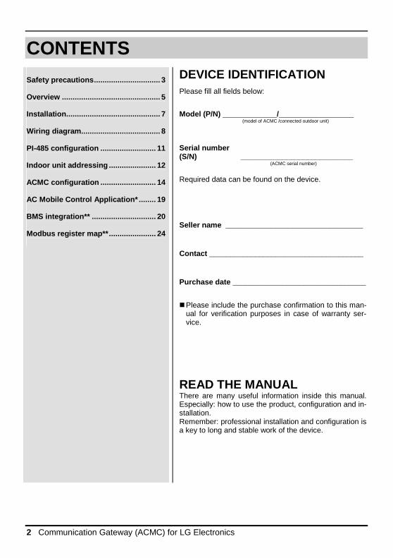
CONTENTS
Safety precautions ............................... 3
Overview .......................................... .... 5
Installation ...................................... ...... 7
Wiring diagram .................................... . 8
PI-485 configuration .......................... 11
Indoor unit addressing ...................... 12
ACMC configuration .......................... 14
AC Mobile Control Application* ........ 19
BMS integration** .............................. 20
Modbus register map** ...................... 24
DEVICE IDENTIFICATION Please fill all fields below:
Model (P/N) _____________/__________________ (model of ACMC /connected outdoor unit)
Serial number (S/N) ___________________________ (ACMC serial number) Required data can be found on the device.
Seller name _________________________________
Contact _____________________________________
Purchase date ________________________________
� Please include the purchase confirmation to this man-
ual for verification purposes in case of warranty ser-vice.
READ THE MANUAL There are many useful information inside this manual. Especially: how to use the product, configuration and in-stallation. Remember: professional installation and configuration is a key to long and stable work of the device.
Safety precautions
Installation manual 3
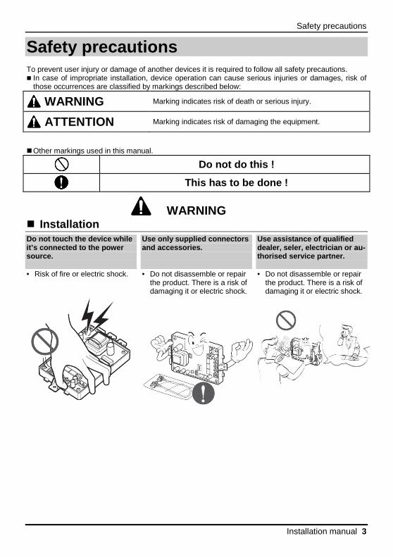
Safety precautions To prevent user injury or damage of another devices it is required to follow all safety precautions. � In case of impropriate installation, device operation can cause serious injuries or damages, risk of
those occurrences are classified by markings described below:
WARNING Marking indicates risk of death or serious injury.
ATTENTION Marking indicates risk of damaging the equipment.
� Other markings used in this manual.
Do not do this !
This has to be done !
WARNING � Installation Do not touch the device while it’s connected to the power source. • Risk of fire or electric shock.
Use only supplied connectors and accessories. • Do not disassemble or repair
the product. There is a risk of damaging it or electric shock.
Use assistance of qualified dealer, seler, electrician or au-thorised service partner. • Do not disassemble or repair
the product. There is a risk of damaging it or electric shock.

Safety precautions
4 Communication Gateway (ACMC) for LG Electronics
Use the correct fuses. • Risk of fire or electric shock.
Customer can’ t install, r e-move, reinstall or uninstall the device by it’s own. • Risk of electric shock and
injury.
For installation always use help of qualified personnel. • Risk of electric shock and injury.
� Operation Contact seler is the product was soaked (flooded or submerged). • Risk of fire or electric shock.
Product can’t be in direct contact with water (also rain, snow, ice). • Risk of fire, electric shock or product damage.

Installation
Installation manual 5
Overview
� Functions
• Remote control of 20* (or 250**) indoor units
• changing indoor units operation modes: Cool / Fan / Dry / Heat / Auto
• changing fan speed: Auto / Low / Medium / Hi / V. Hi / Power
• setting room temperature
• reading actual room temperature
• turning on/off the Swing option
• turning on/off the Plasma option (function availability depends on indoor unit model)
• turning on/off the indoor units
• setting schedules for indoor units (up to 4 for each)*
• turning on/off the local control**
• operation with: AC Mobile Control Application* � Technical data
• Power supply: 9 ÷ 30 V DC
• Dimensions (W x H x D): 110 x 135 x 70 [mm]
• Connected units: many systems (max. 20 junits in the system for HA wersion and 250 units for BMS version)
• Network interface: 10/100BaseT auto-MDIX Ethernet (Modbus TCP**)
• Installation in place without direct exposure to atmospheric agents
*for SYNG1030-HA **for SYNG1030-BMS
Safety precautions
6 Communication Gateway (ACMC) for LG Electronics
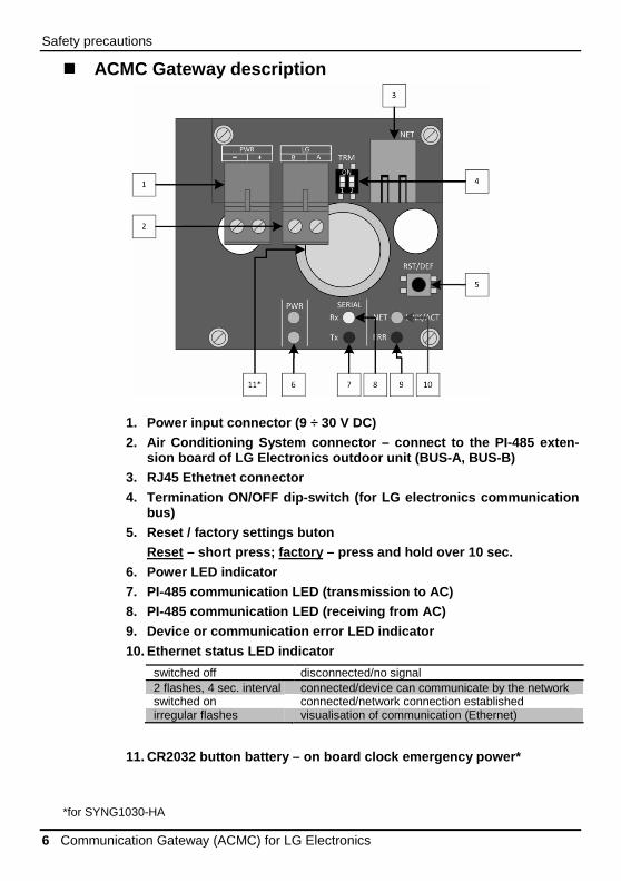
� ACMC Gateway description
1. Power input connector (9 ÷ 30 V DC) 2. Air Conditioning System connector – connect to t he PI-485 exten-
sion board of LG Electronics outdoor unit (BUS-A, B US-B) 3. RJ45 Ethetnet connector
4. Termination ON/OFF dip-switch (for LG electronic s communication bus)
5. Reset / factory settings buton Reset – short press; factory – press and hold over 10 sec.
6. Power LED indicator 7. PI-485 communication LED (transmission to AC) 8. PI-485 communication LED (receiving from AC) 9. Device or communication error LED indicator
10. Ethernet status LED indicator
11. CR2032 button battery – on board clock emergenc y power*
*for SYNG1030-HA
switched off disconnected/no signal 2 flashes, 4 sec. interval connected/device can communicate by the network switched on connected/network connection established irregular flashes visualisation of communication (Ethernet)
Installation
Installation manual 7
Installation
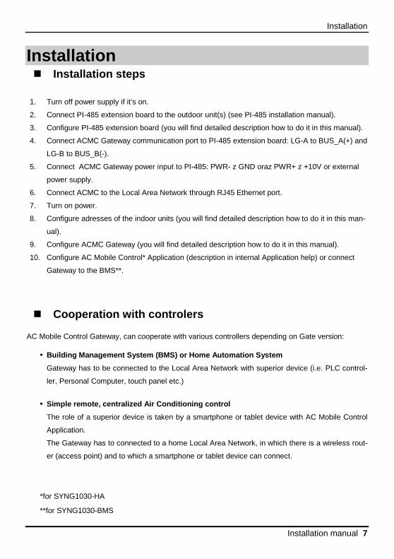
� Installation steps
1. Turn off power supply if it’s on.
2. Connect PI-485 extension board to the outdoor unit(s) (see PI-485 installation manual).
3. Configure PI-485 extension board (you will find detailed description how to do it in this manual).
4. Connect ACMC Gateway communication port to PI-485 extension board: LG-A to BUS_A(+) and
LG-B to BUS_B(-).
5. Connect ACMC Gateway power input to PI-485: PWR- z GND oraz PWR+ z +10V or external
power supply.
6. Connect ACMC to the Local Area Network through RJ45 Ethernet port.
7. Turn on power.
8. Configure adresses of the indoor units (you will find detailed description how to do it in this man-
ual).
9. Configure ACMC Gateway (you will find detailed description how to do it in this manual).
10. Configure AC Mobile Control* Application (description in internal Application help) or connect
Gateway to the BMS**.
� Cooperation with controlers AC Mobile Control Gateway, can cooperate with various controllers depending on Gate version:
• Building Management System (BMS) or Home Automation System
Gateway has to be connected to the Local Area Network with superior device (i.e. PLC control-
ler, Personal Computer, touch panel etc.)
• Simple remote, centralized Air Conditioning control
The role of a superior device is taken by a smartphone or tablet device with AC Mobile Control
Application.
The Gateway has to connected to a home Local Area Network, in which there is a wireless rout-
er (access point) and to which a smartphone or tablet device can connect.
*for SYNG1030-HA
**for SYNG1030-BMS
Installation
8 Communication Gateway (ACMC) for LG Electronics
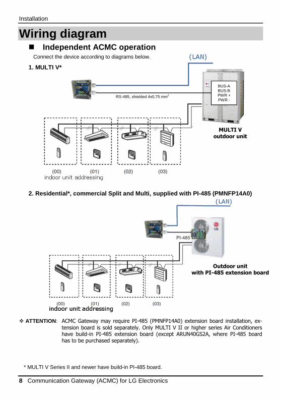
Wiring diagram � Independent ACMC operation
Connect the device according to diagrams below.
1. MULTI V*
2. Residential*, commercial Split and Multi, suppli ed with PI-485 (PMNFP14A0)
� ATTENTION: ACMC Gateway may require PI-485 (PMNFP14A0) extension board installation, ex-
tension board is sold separately. Only MULTI V II or higher series Air Conditioners have build-in PI-485 extension board (except ARUN40GS2A, where PI-485 board has to be purchased separately).
* MULTI V Series II and newer have build-in PI-485 board.
BUS-A BUS-B PWR + PWR -
RS-485, shielded 4x0,75 mm2
Outdoor unit
with PI-485 extension board
MULTI V
outdoor unit
Installation
Installation manual 9
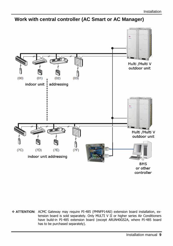
Work with central controller (AC Smart or AC Manage r)
� ATTENTION: ACMC Gateway may require PI-485 (PMNFP14A0) extension board installation, ex-
tension board is sold separately. Only MULTI V II or higher series Air Conditioners have build-in PI-485 extension board (except ARUN40GS2A, where PI-485 board has to be purchased separately).
Installation
10 Communication Gateway (ACMC) for LG Electronics
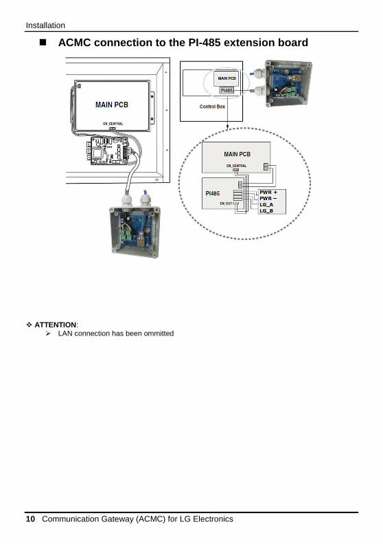
� ACMC connection to the PI-485 extension board
� ATTENTION:
� LAN connection has been ommitted

Installation
Installation manual 11
PI-485 configuration
PI-485 dip switch configuration:
1 i 4 ON, rest OFF
− MULTI V Plus (without MULTI V II or newer and CRUN series) − Multi Split Inverter
3 i 4 ON, rest OFF
− commercial Split and room air conditioners − centrale rekuperacyjne ecoV (PHNFP14A0 board)
ATTENTION Wrong dip-switch setting can cause malfunction.
* - only PI-485 extension board enabled products
always „ON”

Installation
12 Communication Gateway (ACMC) for LG Electronics
Indoor unit addressing
� Wired controller
1. Press and hold the key for more than 3 seconds.
If the key was pressed for less than 3 seconds, the controller will go into user settings mode.
1. Keep pushing the key till you reach address setting mode – the result is visible below.
2. Set up the indoor group number using the temperature adjustment key (range: 0 ~ F).
3. Use keys to select unit number setting.
4. Set up the indoor unit number using the temperature adjustment key (range: 0 ~ F).
5. Press the key to save new settings.
6. Press the key to exit setup mode.
unit no.
group no.
func. code
Installation
Installation manual 13
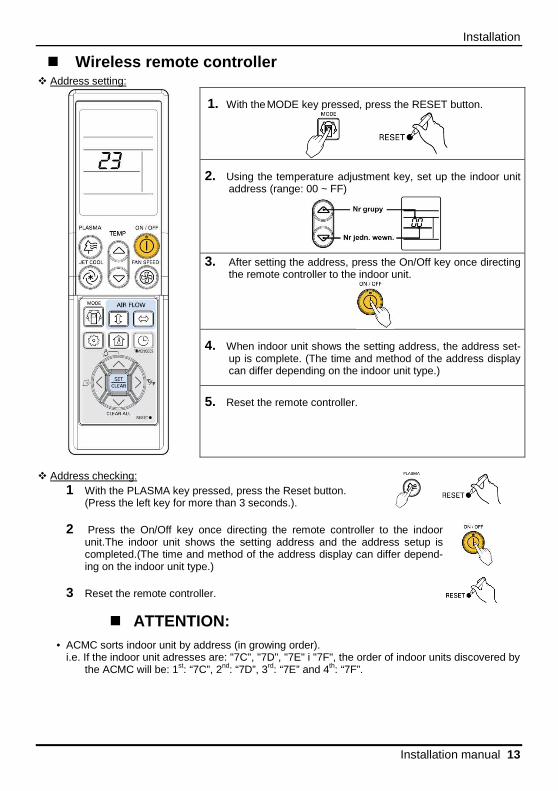
� Wireless remote controller � Address setting:
1. With the MODE key pressed, press the RESET button.
2. Using the temperature adjustment key, set up the indoor unit address (range: 00 ~ FF)
3. After setting the address, press the On/Off key once directing
the remote controller to the indoor unit.
4. When indoor unit shows the setting address, the address set-up is complete. (The time and method of the address display can differ depending on the indoor unit type.)
5. Reset the remote controller.
� Address checking:
1 With the PLASMA key pressed, press the Reset button. (Press the left key for more than 3 seconds.).
2 Press the On/Off key once directing the remote controller to the indoor
unit.The indoor unit shows the setting address and the address setup is completed.(The time and method of the address display can differ depend-ing on the indoor unit type.)
3 Reset the remote controller.
� ATTENTION: • ACMC sorts indoor unit by address (in growing order).
i.e. If the indoor unit adresses are: "7C", "7D", "7E" i "7F", the order of indoor units discovered by the ACMC will be: 1st: “7C”, 2nd: “7D”, 3rd: “7E” and 4th: “7F”.
Installation
14 Communication Gateway (ACMC) for LG Electronics
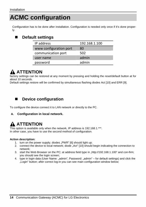
ACMC configuration
Configuration has to be done after installation. Configuration is needed only once if it’s done proper-ly.
� Default settings IP address 192.168.1.100
www configuration port 80
communication port 502
user name admin
password admin
ATTENTION factory settings can be restored at any moment by pressing and holding the reset/default button at for about 10 seconds. Default settings restore will be confirmed by simultaneous flashing diodes Act [10] and ERR [9].
� Device configuration To configure the device connect it to LAN network or directly to the PC. A. Configuration in local network.
ATTENTION This option is available only when the network, IP address is 192.168.1.***. In other case, you have to use the second method of configuration.
Action description:
1. turn on the power supply; diodes „PWR” [6] should light up; 2. connect the device to local network; diode „Act” [10] should begin indicating the connection to
network; 3. start the Web Browser on the PC; at address field type in „http://192.168.1.100” and con-firm;
you should see the login screen; 4. type in login data (User Name: „admin”, Password: „admin” – for default settings) and click the
„Login” button; after correct log-in you can see main configuration window below;
Installation
Installation manual 15
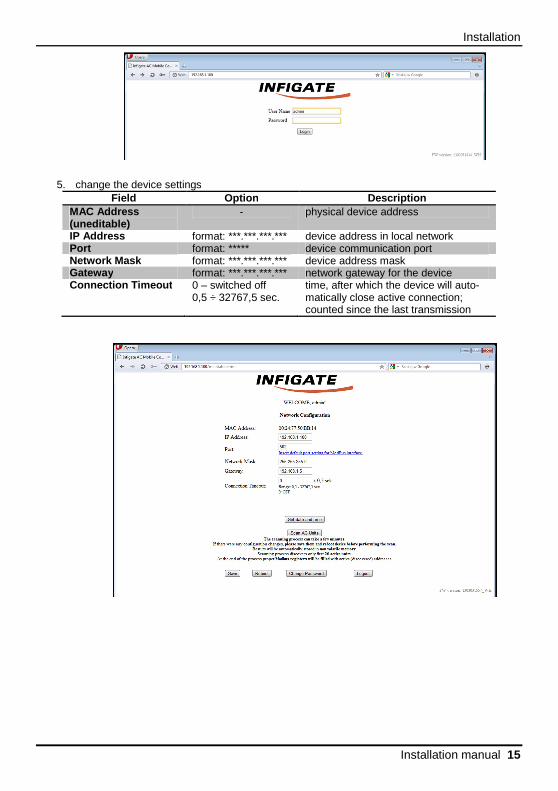
5. change the device settings Field Option Description
MAC Address (uneditable)
- physical device address
IP Address format: ***.***.***.*** device address in local network Port format: ***** device communication port Network Mask format: ***.***.***.*** device address mask Gateway format: ***.***.***.*** network gateway for the device Connection Timeout 0 – switched off
0,5 ÷ 32767,5 sec. time, after which the device will auto-matically close active connection; counted since the last transmission

Installation
16 Communication Gateway (ACMC) for LG Electronics
6. confirm changes in general configuration – by pressing the „Save” button; save confirmation screen will be displayed;
7. device reset – press the „Reboot” button; reboot confirmation screen will be displayed (graph 5); after about 15 seconds you can press the „Refresh” button, which allows you to relogin and ver-ify settings.
ATTENTION New settings will take effect after reboot !
8. (optional – only for SYNG-1030-HA) configure actual date, time and day of week. Click „Set date and time” button. Real Time Clock setting window will appear. Input correct data and click „Save”.

Installation
Installation manual 17
9. scan air-conditioners connected to LG bus. After network interface configuration, you can scan the LG bus. Press „Scan AC Units” button. This engage LG bus scanning process. Start of the process will be confirmed by a confirmation screen. Very important is not to close the device configuration site, until the confirmation page is dis-played. After automatic page reload (you will see main configuration screen), you can log out and close the browser window. Searching process will be uninterrupted. End of searching process is visible in device status register (Modbus), which is described in „Modbus Functions” chapter.

Installation
18 Communication Gateway (ACMC) for LG Electronics
B. Configuration with direct PC connection. Activietes description: 1. turn on the power supply; diodes „PWR” [6] should light up; 2. connect the device to local network; diode „Act” [10] should begin indicating the con-
nection to network; 3. configure PC network card so that both devices are in the same network; example
configuration of network card (in Microsoft Windows 7) is showed at graph 7; configu-ration options in Windows 7 are situated in „Control panel”: Control panel\Web and In-ternet\Network conenction -> properties of network card, which with device is con-nected to;
4. proceed according to instructions included in underpoint „a”, since point 3 inclusive;
Installation
Installation manual 19
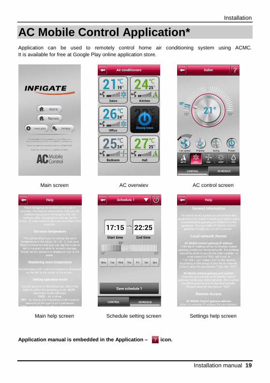
AC Mobile Control Application* Application can be used to remotely control home air conditioning system using ACMC. It is available for free at Google Play online application store.
Main screen
AC overwiev
AC control screen
Main help screen
Schedule setting screen
Settings help screen Application manual is embedded in the Application – icon.
Installation
20 Communication Gateway (ACMC) for LG Electronics
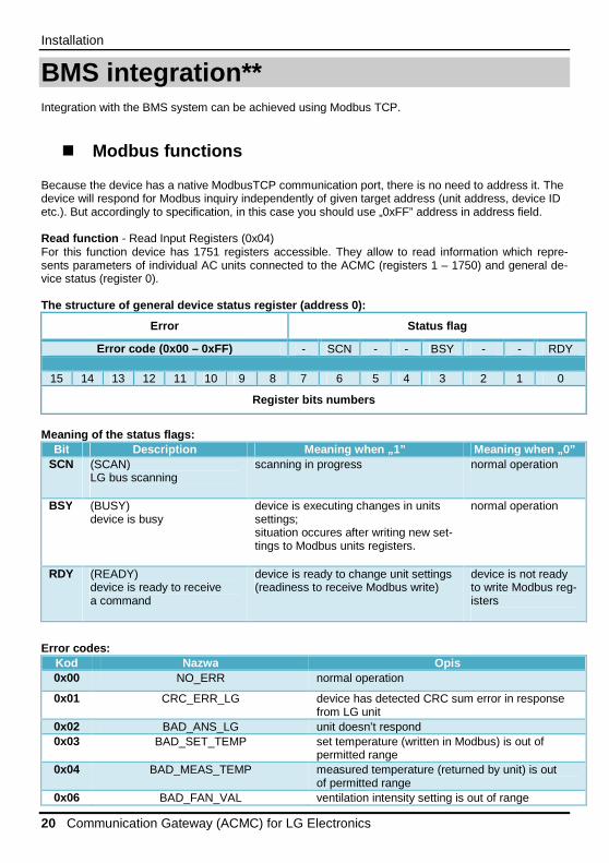
BMS integration** Integration with the BMS system can be achieved using Modbus TCP.
� Modbus functions Because the device has a native ModbusTCP communication port, there is no need to address it. The device will respond for Modbus inquiry independently of given target address (unit address, device ID etc.). But accordingly to specification, in this case you should use „0xFF” address in address field. Read function - Read Input Registers (0x04) For this function device has 1751 registers accessible. They allow to read information which repre-sents parameters of individual AC units connected to the ACMC (registers 1 – 1750) and general de-vice status (register 0). The structure of general device status register (ad dress 0):
Error Status flag
Error code (0x00 – 0xFF) - SCN - - BSY - - RDY
15 14 13 12 11 10 9 8 7 6 5 4 3 2 1 0
Register bits numbers
Meaning of the status flags:
Bit Description Meaning when „1” Meaning when „0” SCN (SCAN)
LG bus scanning
scanning in progress normal operation
BSY (BUSY) device is busy
device is executing changes in units settings; situation occures after writing new set-tings to Modbus units registers.
normal operation
RDY (READY) device is ready to receive a command
device is ready to change unit settings (readiness to receive Modbus write)
device is not ready to write Modbus reg-isters
Error codes: Kod Nazwa Opis 0x00 NO_ERR normal operation
0x01 CRC_ERR_LG device has detected CRC sum error in response from LG unit
0x02 BAD_ANS_LG unit doesn’t respond 0x03 BAD_SET_TEMP set temperature (written in Modbus) is out of
permitted range 0x04 BAD_MEAS_TEMP measured temperature (returned by unit) is out
of permitted range 0x06 BAD_FAN_VAL ventilation intensity setting is out of range
Installation
Installation manual 21
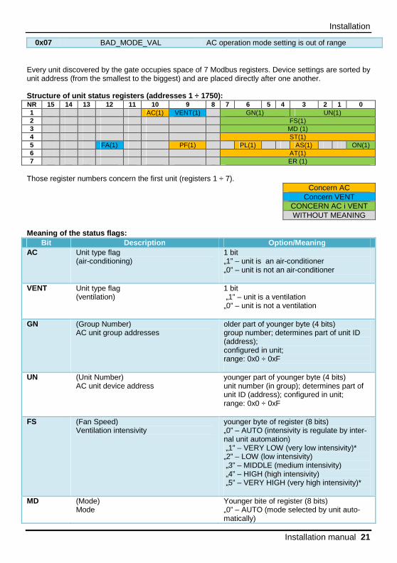
0x07 BAD_MODE_VAL AC operation mode setting is out of range Every unit discovered by the gate occupies space of 7 Modbus registers. Device settings are sorted by unit address (from the smallest to the biggest) and are placed directly after one another. Structure of unit status registers (addresses 1 ÷ 1 750): NR 15 14 13 12 11 10 9 8 7 6 5 4 3 2 1 0 1 AC(1) VENT(1) GN(1) UN(1) 2 FS(1) 3 MD (1) 4 ST(1) 5 FA(1) PF(1) PL(1) AS(1) ON(1) 6 AT(1) 7 ER (1)
Those register numbers concern the first unit (registers 1 ÷ 7).
Concern AC Concern VENT
CONCERN AC i VENT WITHOUT MEANING
Meaning of the status flags:
Bit Description Option/Meaning AC Unit type flag
(air-conditioning) 1 bit „1” – unit is an air-conditioner „0” – unit is not an air-conditioner
VENT Unit type flag (ventilation)
1 bit „1” – unit is a ventilation „0” – unit is not a ventilation
GN (Group Number) AC unit group addresses
older part of younger byte (4 bits) group number; determines part of unit ID (address); configured in unit; range: 0x0 ÷ 0xF
UN (Unit Number) AC unit device address
younger part of younger byte (4 bits) unit number (in group); determines part of unit ID (address); configured in unit; range: 0x0 ÷ 0xF
FS (Fan Speed) Ventilation intensivity
younger byte of register (8 bits) „0” – AUTO (intensivity is regulate by inter-nal unit automation) „1” – VERY LOW (very low intensivity)* „2” – LOW (low intensivity) „3” – MIDDLE (medium intensivity) „4” – HIGH (high intensivity) „5” – VERY HIGH (very high intensivity)*
MD (Mode) Mode
Younger bite of register (8 bits) „0” – AUTO (mode selected by unit auto-matically)
Installation
22 Communication Gateway (ACMC) for LG Electronics
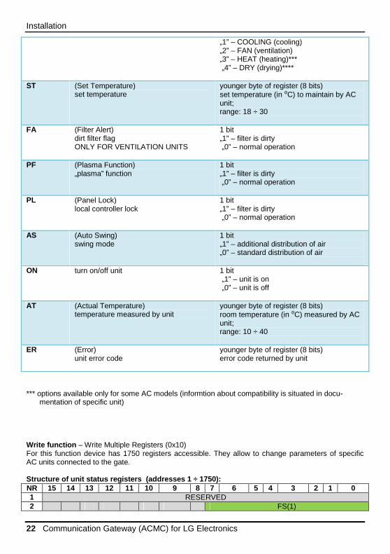
„1” – COOLING (cooling) „2” – FAN (ventilation) „3” – HEAT (heating)*** „4” – DRY (drying)****
ST (Set Temperature) set temperature
younger byte of register (8 bits) set temperature (in ⁰C) to maintain by AC unit; range: 18 ÷ 30
FA (Filter Alert) dirt filter flag ONLY FOR VENTILATION UNITS
1 bit „1” – filter is dirty „0” – normal operation
PF (Plasma Function) „plasma” function
1 bit „1” – filter is dirty „0” – normal operation
PL (Panel Lock) local controller lock
1 bit „1” – filter is dirty „0” – normal operation
AS (Auto Swing) swing mode
1 bit „1” – additional distribution of air „0” – standard distribution of air
ON turn on/off unit 1 bit „1” – unit is on „0” – unit is off
AT (Actual Temperature) temperature measured by unit
younger byte of register (8 bits) room temperature (in ⁰C) measured by AC unit; range: 10 ÷ 40
ER (Error) unit error code
younger byte of register (8 bits) error code returned by unit
*** options available only for some AC models (informtion about compatibility is situated in docu-
mentation of specific unit) Write function – Write Multiple Registers (0x10) For this function device has 1750 registers accessible. They allow to change parameters of specific AC units connected to the gate. Structure of unit status registers (addresses 1 ÷ 1750): NR 15 14 13 12 11 10 9 8 7 6 5 4 3 2 1 0 1 RESERVED 2 FS(1)

Installation
Installation manual 23
3 MD (1) 4 ST(1) 5 PF(1) PL(1) AS(1) ON(1) 6 RESERVED 7 RESERVED
Those register numbers concern the first unit (registers 1 ÷ 7).
Concern AC Concern VENT
CONCERN AC i VENT WITHOUT MEANING
Meaning of individual fields is identical with description for read function. Registers which contain ad-dress and device type, current temperature and error code are registers only for reading. So they are not available in function „Write Multiple Registers”.
ATTENTION • You should not write to more than one unit in the same time. • Before you start to writeModbus registes, you should definitely check device readiness flag
(look: general status register). • Every unit parameter write should include full set of its parameters.

Installation
24 Communication Gateway (ACMC) for LG Electronics
Modbus register map** Table below describes placement of the Modbus registers of ACMC. Meaning of particular bits were described in previous sections of this manual.
Notes
Communication Gateway (ACMC) for LG Electronics 25

Notes
26 Communication Gateway (ACMC) for LG Electronics

Notes
Communication Gateway (ACMC) for LG Electronics 27

Infigate Technology Sp. z o.o. Walbrzyska 11/85 02-739 Warsaw, Poland oreders : [email protected] support : [email protected] www.infigate.com