accessories - abb group · accessories - 2 - wireless automation ... for that reason the...
TRANSCRIPT

Technical Description
Wireless AutomationAccessories
- 2 -Accessories
Wireless Automation AccessoriesTechnical description
Wireless Automation / Issue: 07.2012
Please note the following
Target group
This description is intended for the use of trained specialists in electrical installation and control and auto-mation engineering, who are familiar with the applicable national standards.
Safety requirements
The responsible staff must ensure that the application or use of the products described satisfy all the requirements for safety, including all the relevant laws, regulations, guidelines and standards.
Liability
The documentation has been prepared with care. The products described are, however, constantly under development. For that reason the documentation is not in every case checked for consistency with per-formance data, standards or other characteristics, and does not represent an assurance of characteristics in the sense of § 459, Para. 2 of the German Civil Code. In the event that it contains technical or editorial errors, we retain the right to make alterations at any time and without warning.
No claims for the modification of products that have already been supplied may be made on the basis of the data, diagrams and descriptions in this documentation.
© This manual is copyrighted. Any reproduction or third party use of this protected publication, whether in whole or in part, without the written permission of ABB Automation Products GmbH, is forbidden.

- 3 - Accessories
Wireless Automation AccessoriesTechnical description
Wireless Automation / Issue: 07.2012
Content
WSC100-N000 Holder for communication module WSIX100 with M12 feedthrough ..........................4
WSC100-N003 Connection cable (0.3m) and holder for communication module ................................5
WSC100-N006 Connection cable (0.6m) and holder for communication module ................................5
WSC100-N007 Connection cable (0.7m) and holder for communication module ................................5
WSC100-N010 Connection cable (1.0m) and holder for communication module ................................5
SZC7-5pol-S 7/8"-connector, socket, 5 pole for I/O pad WIOP100 ..................................................7
SZC7-5pol-P 7/8"-connector, plug, 5 pole for I/O pad WIOP100......................................................8
SZC1-YU0 Y-connector M12 plug (5 pole) onto 2 x M12 socket (5-polig) for 2 sensors or actuators ......................................................................................................................9
SZC8-YU0 Y-connector M12 plug (5-pole) onto 2 x M8 socket (3 pole) for 2 sensors or actuators ....................................................................................................................10
WSC1-YU0 Y-connector M12 plug (5-pole) onto 2 x M8 socket (3 pole) for 2 sensor pads WSP ...........................................................................................................................11
WPI100 Wireless Power Indicator ...........................................................................................12

- 4 -
WSIX100
67 14
60
23
Accessories
Wireless Automation AccessoriesTechnical description
Wireless Automation / Issue: 07.2012
WSC100-N000Fixing bracket with M12 feedthrough male/female for WSIX communication module connection via a user cable to the WSIN/WSIF sensor heads.
Description
Feedthrough Receptacle
M12 male connector for WSIX connection (without pin1), extended thread for fastening to the fixing bracket, 3 pins (2,4,3), pin assigment same as WSIX100
M12 jack 5 pin for user cable (4 pole)
EMC tests were done with a length of 3 m (unshielded cable)
Electrical Data
Nominal voltage < 300 V AC
Test voltage 2.0 kV
Temperature range -25°C ... + 80°C
Mechanical data
Degree of protection IP 67 (only in fully locked position)
fixing bracket high-grade steel
thickness: 2 mm, 2 slotted holes for M6 screws
Ordering data
Type Cable length Order number EAN number
WSC100-N000 0,0 m 1SAF 900 100 R1000 4013614386336
Fig. 1a: WSC100-N000
All dimensions in mm
fixing bracket high-grade steel (2 mm), 2 slotted holes for M6 screws
Fig. 1b: Mechanical dimensions
M12 female
M12 male

- 5 -
2421
Accessories
Wireless Automation AccessoriesTechnical description
Wireless Automation / Issue: 07.2012
WSC100-N003, WSC100-N006, WSC100-N007, WSC100-N010
Connection cable and holder for communication module WSIX100, assembled (0.3 m / 0.6 m / 0.7 m /1.0 m)
Description
Connection cable free of halogen, resistant to ultraviolet rays (only indoor)
conductor bare litz wire (Cu) 43 x 0.1 mm diameter, extra finely stranded, 0.34 mm²
insulation PP (Polypropylen), core diameter 1.3 mm
sheath TPU Polyetheruethan, colour: black, external diameter 4.3 mm
M12 right-angle plug extended threat and square for fastening to the fixing bracket; 3 pins (2,4,3); pin assigment same as WSIX100 (pin 1 missing)
M12 right-angle jack 3 contacts (2,4,3); pin assigment same as WSIX100 (contact 1 sealed)
fixing bracket high-grade steel
thickness: 2 mm, 2 slotted holes for M6 screws, square location hole for the right-angle plug
Electrical Data
Nominal voltage < 300 V AC
Test voltage 2.0 kV
Temperature range moved as trailing cable
-25°C ... + 80°C + 60°C
Mechanical data
Degree of protection IP 67 (only in fully locked position) Good resistance to oil and chemicals
Bending radius static dynamic
25 mm 50 mm
Scope of delivery: Cable, assembled with M12 plug and M12 jack (both are right-angle), a M12 nut, a washer and a fixing bracket (high-grade steel)
Fig. 2: Mounting configuration WSC100-N0xx
communication module
washer
nut
fixing bracket (high-grade steel) connection cable, 3 pole
All dimensions in mm
M12 plug M12 jack
sensor

- 6 -
WSIX100
66 16,5
60
23
Accessories
Wireless Automation AccessoriesTechnical description
Wireless Automation / Issue: 07.2012
WSC100-N003, WSC100-N006, WSC100-N007, WSC100-N010
Connection cable and holder for communication module WSIX100, assembled (0.3 m / 0.6 m / 0.7 m /1.0 m)
Ordering data
Type Cable length Order number EAN number
WSC100-N003 0,3 m 1SAF 900 100 R1003 4013614379444
WSC100-N006 0,6 m 1SAF 900 100 R1006 4013614379468
WSC100-N007 0.7m 1SAF 900 100 R1007 4013614382864
WSC100-N010 1,0 m 1SAF 900 100 R1010 4013614379505
Fig. 3: Mechanical dimensions
All dimensions in mm
fixing bracket high-grade steel (2 mm), 2 slotted holes for M6 screws

- 7 -
SZC7-5pol-S
*a Montagehilfepin or screwdriver asassembly tool
*b O-ringO-Ring
Stift oder Schraubendreher als
3
1
2 4
5
Accessories
Wireless Automation AccessoriesTechnical description
Wireless Automation / Issue: 07.2012
Technical data
Temperature range -40°C ... + 90°C
Electrical data
Contact resistance m 5 m q
Nominal current at 40°C 9 A
Nominal voltage 240 V
Rated voltage 250 V
Test voltage 2.0 kV eff. / 60s
Insulation resistance L 109 q
Pollution degree 3
Mechanical data
Degree of protection IP 67 (Only in locked position with its proper counterparts.)
The application of these products in harsh environ-ments should always be checked before use
Mode of connection screw terminals
Connectable conductor max. 1.0 mm2
Screw joint for cable X 8.0 - 10.0 mm2
Materials
Housing / Molded body PA
Insert TPU, self-extinguishing
Contact CuZn, pre-nickeled and 0.8 mm gold-plated
Receptacle shell / knurled screw / nut / hexagon screw / hexagon nut / sleeve Al anodized
O-Ring NBR
Ordering data
Type Order number EAN number
SZC7-5pol-S 1SAF 938 781 R1000 4013614389436
All dimensions in mm
Mechanical dimensions
*a pin or screwdriver as assembly tool *b O-ring
SZC7-5pol-S
7/8"-connector (socket 5 pole) for I/O pad WIOP100, assembling with screw terminals
Fig. 4:

- 8 -
*a O-ring
*b Stift oder Schraubendreher als Montagehilfepin or screwdriver asassembly tool
* Kontakt 1,5 voreilendcontact 1.5 leading
*
O-Ring
3
1
24
5
SZC7-5pol-P
Accessories
Wireless Automation AccessoriesTechnical description
Wireless Automation / Issue: 07.2012
Fig. 5:
*a pin or screwdriver as assembly tool *b O-ring
contact 1.5 leadingd
Technical data
Temperature range -40°C ... + 90°C
Electrical data
Contact resistance m 5 m q
Nominal current at 40°C 9 A
Nominal voltage 240 V
Rated voltage 250 V
Test voltage 2.0 kV eff. / 60s
Insulation resistance L 109 q
Pollution degree 3
Mechanical data
Degree of protection IP 67 (Only in locked position with its proper counterparts.)
The application of these products in harsh environ-ments should always be checked before use.
Mode of connection screw terminals
Connectable conductor max. 1.0 mm2
Screw joint for cable X 8.0 - 10.0 mm2
Materials
Housing / Molded body PA
Insert TPU, self-extinguishing
Contact CuZn, pre-nickeled and 0.8 mm gold-plated
Receptacle shell / knurled screw / nut / hexagon screw / hexagon nut / sleeve Al anodized
O-Ring NBR
Ordering data
Type Order number EAN number
SZC7-5pol-P 1SAF 938 780 R1000 4013614389429
SZC7-5pol-P
7/8"-connector (plug 5 pole) for I/O pad WIOP100, assembling with screw terminals
All dimensions in mm
Mechanical dimensions

- 9 -
SZC1-YU0
*a Mutter schwarzcoupling nut black
*b Mutter vernickeltcoupling nut nickel-plated
*c O-RingO-ring
A B
1 432 5
1 432 5 1 432 5
Accessories
Wireless Automation AccessoriesTechnical description
Wireless Automation / Issue: 07.2012
Technical data
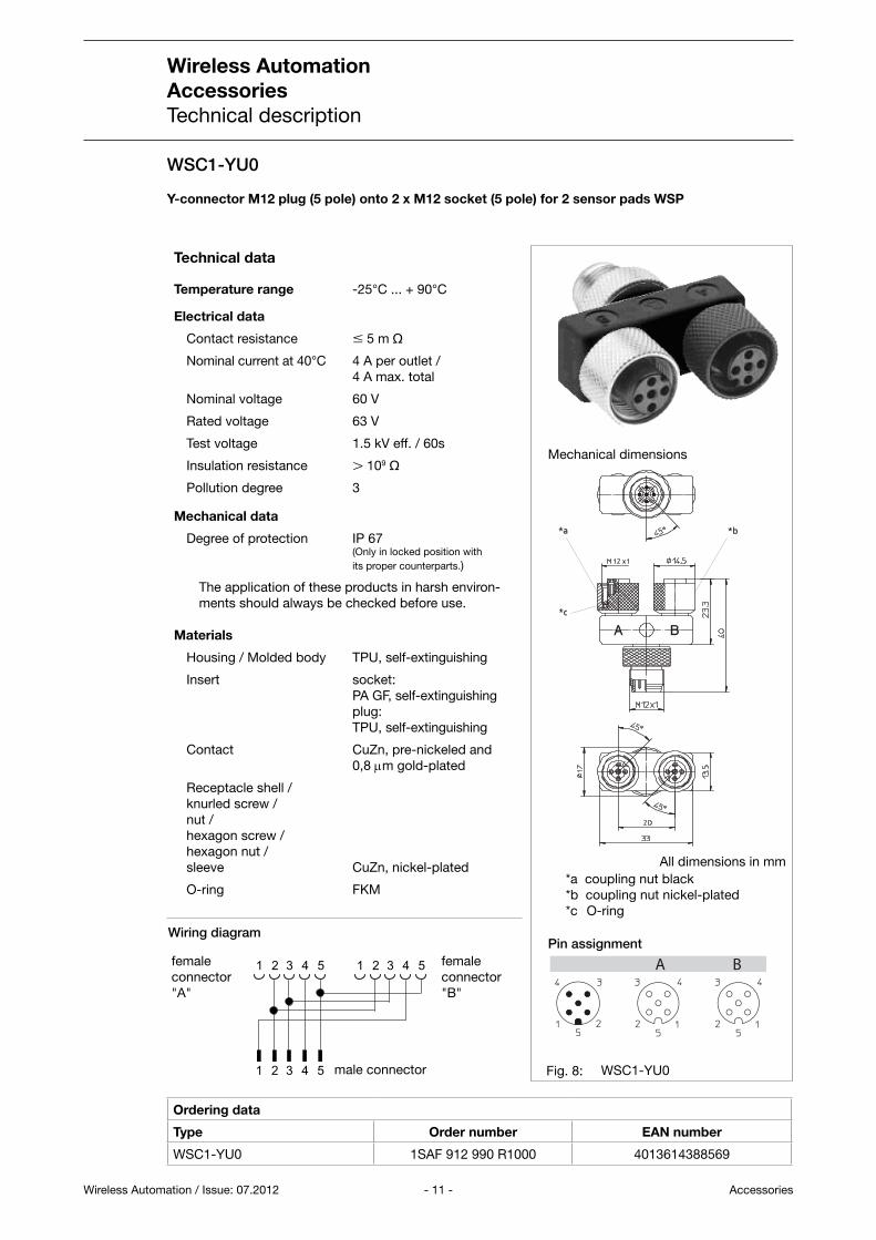
Temperature range -25°C ... + 90°C
Electrical data
Contact resistance m 5 m q
Nominal current at 40°C 4 A per outlet / 4 A max. total
Nominal voltage 60 V
Rated voltage 63 V
Test voltage 1.5 kV eff. / 60s
Insulation resistance L 109 q
Pollution degree 3
Mechanical data
Degree of protection IP 67 (Only in locked position with its proper counterparts.)
The application of these products in harsh environ-ments should always be checked before use.
Materials
Housing / Molded body TPU, self-extinguishing
Insert socket: PA GF, self-extinguishing plug: TPU, self-extinguishing
Contact CuZn, pre-nickeled and 0,8 mm gold-plated
Receptacle shell / knurled screw / nut / hexagon screw / hexagon nut / sleeve CuZn, nickel-plated
O-ring FKM
Ordering data
Type Order number EAN number
SZC1-YU0 1SAF 912 910 R1000 4013614386343
SZC1-YU0
Y-connector M12 plug (5 pole) onto 2 x M12 socket (5 pole) for 2 sensors or actuators
All dimensions in mm
Mechanical dimensions
Fig. 6:
*a coupling nut black *b coupling nut nickel-plated *c O-ring
Pin assignment
male connector
female connector "A"
female connector "B"
Wiring diagram

- 10 -
SZC8-YU0
A B
Mutter schwarz Mutter vernickelt
coupling nut black coupling nut nickel-plated
*a *b
*a *b
1 432
1 43 1 43
Accessories
Wireless Automation AccessoriesTechnical description
Wireless Automation / Issue: 07.2012
Ordering data
Type Order number EAN number
SZC8-YU0 1SAF 912 911 R1000 4013614391217
SZC8-YU0
Y-connector M12 plug (5 pole) onto 2 x M8 socket (3 pole) for 2 sensors or actuators
Technical data
Temperature range -25°C ... + 90°C
Electrical data
Contact resistance m 5 m q
Nominal current at 40°C 4 A per outlet / 4 A max. total
Nominal voltage 60 V
Rated voltage 63 V
Test voltage 1.5 kV eff. / 60s
Insulation resistance L 109 q
Pollution degree 3
Mechanical data
Degree of protection IP 67 (Only in locked position with its proper counterparts.)
The application of these products in harsh environ-ments should always be checked before use.
Materials
Housing / Molded body TPU, self-extinguishing
Insert socket: TPU, self-extinguishing plug: TPU, self-extinguishing
Contact CuZn, pre-nickeled and 0,8 mm gold-plated
Receptacle shell / knurled screw / nut / hexagon screw / hexagon nut / sleeve CuZn, nickel-plated
O-ring FKM
All dimensions in mm
Mechanical dimensions
Fig. 7:
*a coupling nut black *b coupling nut nickel-plated
Pin assignment
male connector
female connector "A"
female connector "B"
Wiring diagram
- 11 -
WSC1-YU0
*a Mutter schwarzcoupling nut black
*b Mutter vernickeltcoupling nut nickel-plated
*c O-RingO-ring
A B
1 432 5
1 432 5 1 432 5
Accessories
Wireless Automation AccessoriesTechnical description
Wireless Automation / Issue: 07.2012
Ordering data
Type Order number EAN number
WSC1-YU0 1SAF 912 990 R1000 4013614388569
WSC1-YU0
Y-connector M12 plug (5 pole) onto 2 x M12 socket (5 pole) for 2 sensor pads WSP
Technical data
Temperature range -25°C ... + 90°C
Electrical data
Contact resistance m 5 m q
Nominal current at 40°C 4 A per outlet / 4 A max. total
Nominal voltage 60 V
Rated voltage 63 V
Test voltage 1.5 kV eff. / 60s
Insulation resistance L 109 q
Pollution degree 3
Mechanical data
Degree of protection IP 67 (Only in locked position with its proper counterparts.)
The application of these products in harsh environ-ments should always be checked before use.
Materials
Housing / Molded body TPU, self-extinguishing
Insert socket: PA GF, self-extinguishing plug: TPU, self-extinguishing
Contact CuZn, pre-nickeled and 0,8 mm gold-plated
Receptacle shell / knurled screw / nut / hexagon screw / hexagon nut / sleeve CuZn, nickel-plated
O-ring FKM
All dimensions in mm
Mechanical dimensions
Fig. 8:
*a coupling nut black *b coupling nut nickel-plated *c O-ring
Pin assignment
male connector
female connector "A"
female connector "B"
Wiring diagram

- 12 -
2CD
C35
1037
F000
8
Accessories
Wireless Automation AccessoriesTechnical description
Wireless Automation / Issue: 07.2012
WPI100 - Wireless Power Indicator
Warning!
Service device only - No Measurement device! Do not use in continuous operation
WPI100 - Wireless Power Indicator
(foil-switch, without function)
Front label
Yellow LED / Green LED Display for Indication of wireless power
WPI100 - View, indicators and operating elements
M12 plug with sleeve nut
Type plate incl. ordering number of the WPI100
Purpose and short description
The WPI100 (Wireless Power Indicator) is used for indicating the field strength needed for the function of a wireless power product, especially the wireless proximity switch WSIX or sensor pad WSP.
It may not be used as measurement device for analysis of a regulatory sitiation. Such analysis have to be done via calculations as described in the planning and installation manual, simulations or via official calibrated measurement devices (as stated by the regulations and the BG in Germany)
Functions of the WPI100
The WPI100 has the following functions:1. Indication of Wireless power availability and quality via LEDs
2. Remote reading of field strength with a standard voltmeter (proportional voltage generated)
- 13 -
+-1V ~ 1A/m
± 15 %
WPI100
+-1
3
5
+
-
WPI100
WPI100
Accessories
Wireless Automation AccessoriesTechnical description
Wireless Automation / Issue: 07.2012
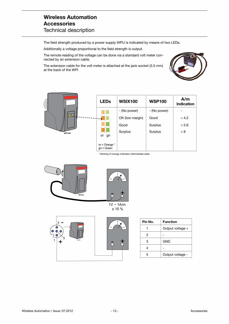
The field strength produced by a power supply WPU is indicated by means of two LEDs.
Additionally a voltage proportional to the field strength is output.
The remote reading of the voltage can be done via a standard volt meter con-nected by an extension cable.
The extension cable for the volt meter is attached at the jack socket (3.5 mm) at the back of the WPI
Pin No. Function
1 Output voltage +
2 -
3 GND
4 -
5 Output voltage -
LEDs WSIX100 WSP100 A/m Indication
or gn
- (No power) - (No power) -
OK (low margin) Good > 4.2
Good Surplus > 5.6
Surplus Surplus > 8
or = Orange *) gn = Green*) blinking of orange indicates intermediate state

- 14 -Accessories
Wireless Automation AccessoriesTechnical description
Wireless Automation / Issue: 07.2012
Ordering data
Type Ordering number EAN number
WPI100 1SAF 902 800 R1000 4013614395611
Label 1SVR 366 017 R0100 4016779570459
Technical data
Diagnosis indication LEDs, orange / greenOperating temperature -25 ... +55 °CStorage temperature -40 ... +70 °CConnection voltmeter 3.5 mm jack socket (alternative M12 socket) Frequency of fields trength 120 kHzWeight 125 g

- 15 -
46
58
15,5
31
20
WPI 100
31
53
WS
IX 100
1SA
F900100R3000
52
16
53
45,5
57,5
1200
2 x 0.5 mm2
1SV
C11
0000
F018
1
Accessories
Wireless Automation AccessoriesTechnical description
Wireless Automation / Issue: 07.2012
WPI100, mechanical dimensions
Mechanical dimensions
WPI100 - Extension cable for the volt meter, mechanical dimensions
Label for WPI100
All dimensions in mm
Note:
We reserve the right to make technical changes or
modify the contents of this document without prior
notice. With regard to purchase orders, the agreed
particulars shall prevail. ABB AG does not accept
any responsibility whatsoever for potential errors or
possible lack of information in this document.
We reserve all rights in this document and in the
subject matter and illustrations contained therein.
Any reproduction, disclosure to third parties or
utilization of its contents – in whole or in parts – is
forbidden without prior written consent of ABB AG.
Copyright© 2012 ABB
All rights reserved
Contact us
3AD
R07
1009
D02
01
07.2
012
ABB Automation Products GmbHWallstadter Str. 5968526 Ladenburg, GermanyPhone: +49 62 21 701 1444Fax : +49 62 21 701 1382E-Mail: [email protected]
www.abb.com/plc