accommodation of the carbonate ion in fluorapatite synthesized at
TRANSCRIPT

American Mineralogist, Volume 93, pages 1460–1469, 2008
0003-004X/08/0809–1460$05.00/DOI: 10.2138/am.2008.2786 1460
Accommodation of the carbonate ion in fluorapatite synthesized at high pressure
Michael e. Fleet* and Xi liu
Department of Earth Sciences, University of Western Ontario, London, Ontario N6A 5B7, Canada
abstract
Sodium-bearing, type A-B carbonate fluorapatites {Ca10–1.5yNayn0.5y[(PO4)6–2y(CO3)2y][F2–2x(CO3)x], with x ≈ y ≈ 0.1; CFAP} have been synthesized at 1150–1300 °C and 1.0 GPa, and investigated by single-crystal X-ray diffraction and FTIR spectroscopy. Typical crystal and compositional data are a = 9.3659(3), c = 6.8901(4) Å, space group P63/m, R = 0.023, Rw = 0.021, x = 0.14(3), and 2y = 0.23(1). Crystal-chemical features and FTIR spectra are similar to Na-bearing, type A-B carbonate hydroxy-lapatites (CHAP) reported recently. However, uptake of carbonate is significantly lower in CFAP than in CHAP for similar conditions of crystal synthesis. Structural accommodation of the substitutions requires local coupling of the Na cation and channel (type A) and phosphate (type B) carbonate ion defects, as in CHAP but now in the approximate ratio 1:1:2. The type B carbonate ion is located on the sloping faces of the substituted phosphate group, and tilted only 3.5° from the mirror plane. The presence of weak electron density in the outer wall of the c-axis channel of apatite and in triangular coordination with one Ca1 and two Ca2 cations appears to represent a trace amount of excess fluoride, the controversial crystal-chemical feature of francolite.
Keywords: Apatite structure, fluorapatite, carbonate ion, biomineralization, dental enamel, crystallography
introduction
The crystal chemistry of carbonate in hydroxylapatite [Ca10(PO4)6(OH)2; HAP] and fluorapatite [Ca10(PO4)6F2; FAP] has been extensively investigated (e.g., LeGeros et al. 1969; McClellan and Lehr 1969; Bonel 1972; Elliott 1964, 1994, 2002; Perdikatsis 1991; McClellan 1980; Beshah et al. 1990; Regnier et al. 1994; Nathan 1996; Comodi and Liu 2000; El Feki et al. 2000; Leventouri et al. 2000, 2001; Suetsugu et al. 2000; Ivanova et al. 2001; Boskey 2003; Fleet and Liu 2003, 2004, 2005, 2007; Fleet et al. 2004; Wopenka and Pasteris 2005; Wilson et al. 1999, 2004, 2006; Antonakos et al. 2007; Rey et al. 2007) and found to be complex. The carbonate ion can be accommodated in either the c-axis structural channel or as a substituent for the phosphate group: the former is known as type A carbonate and the latter as type B. Carbonate-bearing HAP is herewith abbreviated as CHAP and carbonate-bearing FAP as CFAP. Study of apatite biomineralization and of apatite synthesized under low-temperature laboratory conditions has been limited by small crystal size. This problem has been circumvented in our laboratory by crystallizing apatites from carbonate-rich bulk compositions at high temperature and pressure (1–3 GPa), allow-ing study by single-crystal X-ray diffraction methods. We found that the type A carbonate ion was oriented in the apatite channel with two O atoms close to the c axis, but with precise location and orientation dependent on bulk apatite composition (Fleet and Liu 2003, 2005, 2007). The type B carbonate ion was located close to the sloping faces of the substituted PO4 group (Fleet and
Liu 2004, 2007; Fleet et al. 2004), in agreement with the neutron powder diffraction study of Wilson et al. (2004). Fleet and Liu (2007) investigated a suite of Na-bearing, type A-B CHAP of general composition Ca10–yNay[(PO4)6–y(CO3)y][(OH)2–2x(CO3)x], x ≈ y ≤ 1.0. They showed that the Na cation and channel and phosphate carbonate ion defects were coupled locally by charge and spatial compensation requirements. Moreover, one synthetic preparation was equivalent in composition and infrared spectrum to apatite in bone and human dental enamel (cf. Aparicio et al. 2002; Elliott 2002;), allowing these important biomineralizations to be reinterpreted as Na-bearing, type A-B CHAP with channel carbonate up to 50% of total carbonate. We recognize that the biomineralization in bone does differ from high-temperature crystallized HAP with respect to nanocrystalline grain size, poor crystallinity, and lack of Raman and infrared bands for structur-ally bound hydroxyl (e.g., Wopenka and Pasteris 2005).
We presently use the high-pressure synthesis approach to investigate the accommodation of the carbonate ion in FAP. Beyond the evident crystal-chemical interest (e.g., Antonakos et al. 2007; McClellan 1980; Beshah et al. 1990; Regnier et al. 1994; Nathan 1996), fluoride hosted by CHAP is the important anticaries component of dental enamel; there is only ~100 ppm F in the interior of dental enamel (Elliott 2002) but up to 1 wt% in the outermost micrometer-scale layer (Brudevold et al. 1956). Moreover, fluorapatite is a practical host for the containment of high-level nuclear waste, as evidenced by its occurrence in the natural reactor at Oklo, Gabon (e.g., Bros et al. 1996). This study also provides an opportunity to compare the uptake of carbonate by HAP and FAP from high-temperature melts. * E-mail: [email protected]
FLEET AND LIU: SyNTHETIC CARBONATE FLUORAPATITE 1461
eXperiMental MethodsSingle crystals of CFAP were prepared by direct reaction of analytical grade
reagents (Ca2P2O7, CaF2, CaCO3, Na2CO3, ±CaO) at high pressure and temperature using a Depths of the Earth Company Quickpress piston-cylinder apparatus. The starting materials were mixed in the stoichiometric proportions of the nominal type-B CFAP composition Ca8Na2[(PO4)4(CO3)2]F2 with selected components in excess, as reported in the footnote to Table 1. Calcium fluoride (CaF2) and Ca2P2O7 were heated at 800 °C for 24 h to remove water, CaCO3 and Na2CO3 were dried at 200 °C and 1 atm for 48 h, and CaO was heated at 1050 °C for 12 h to eliminate traces of CaCO3. Starting materials were mixed and ground under acetone in an agate mortar, and stored at 110 °C. In addition, furnace parts were previously fired at 1000 °C in air. The starting mixture was encapsulated in a sealed platinum tube, with a diameter of 5 mm and a height of 10 mm, which was separated by crushable MgO tubing from a graphite sleeve. Operation of the piston-cylinder apparatus is detailed in Fleet et al. (2004). Run conditions are summarized in Table 1. All experiments were quenched at pressure by switching off the furnace.
The products were characterized by optical microscopy, powder X-ray diffrac-tion (XRD Rigaku D/MAX-B rotating anode system; CoKα X-radiation), electron probe micro-analysis (EPMA; JEOL JXA-8600, using a lead stearate spectrometer crystal for carbon), and Fourier transform infrared (FTIR) spectroscopy (Nicolet Nexus 670 FTIR spectrometer). The infrared spectra were obtained for both hand-separated CFAP crystals and bulk samples using KBr pellets (Fig. 1). About 10 mg of apatite crystal product was first ground to a powder, then diluted in an agate mortar with 1 g of KBr, and ground under an infrared heating lamp to a grain size <25 µm. Transparent pellets were made under vacuum at a pressure of 200 kg/cm2.
The temperature of the sample under the infrared heating lamp was 60 ± 5 °C, and the exposure time was typically 10–30 min.
Prismatic single crystals from experiments LM130, LM136, and LM142 (Table 1) were evaluated for X-ray structure analysis by optical microscopy. Single-crystal measurements were made at room temperature and pressure with a Nonius Kappa CCD diffractometer and graphite-monochromatized MoKα X-radiation (50 kV, 32 mA, λ = 0.7107 Å). The COLLECT software (Nonius 1997) was used for unit-cell refinement and data collection. The reflection data were processed with SORTAV-COLLECT, using an empirical procedure for absorption correction, and SHELXTL/PC (Siemens 1993). Structure refinements were made with LINEX77 (Coppens 1977). Scattering factors for neutral-atomic species and values of the anomalous scattering factors f ′ and f″ were taken, respectively, from Tables 2.2A and 2.3.1 of the International Tables for X-ray Crystallography (Ibers and Ham-ilton 1974). Relevant experimental details are given in Table 2, final parameters in Tables 3 and 4, selected bond distances in Table 5, and observed and calculated structure factors in Table 61.
results and discussion
Experimental productsThe products of the five experiments listed in Table 1 were
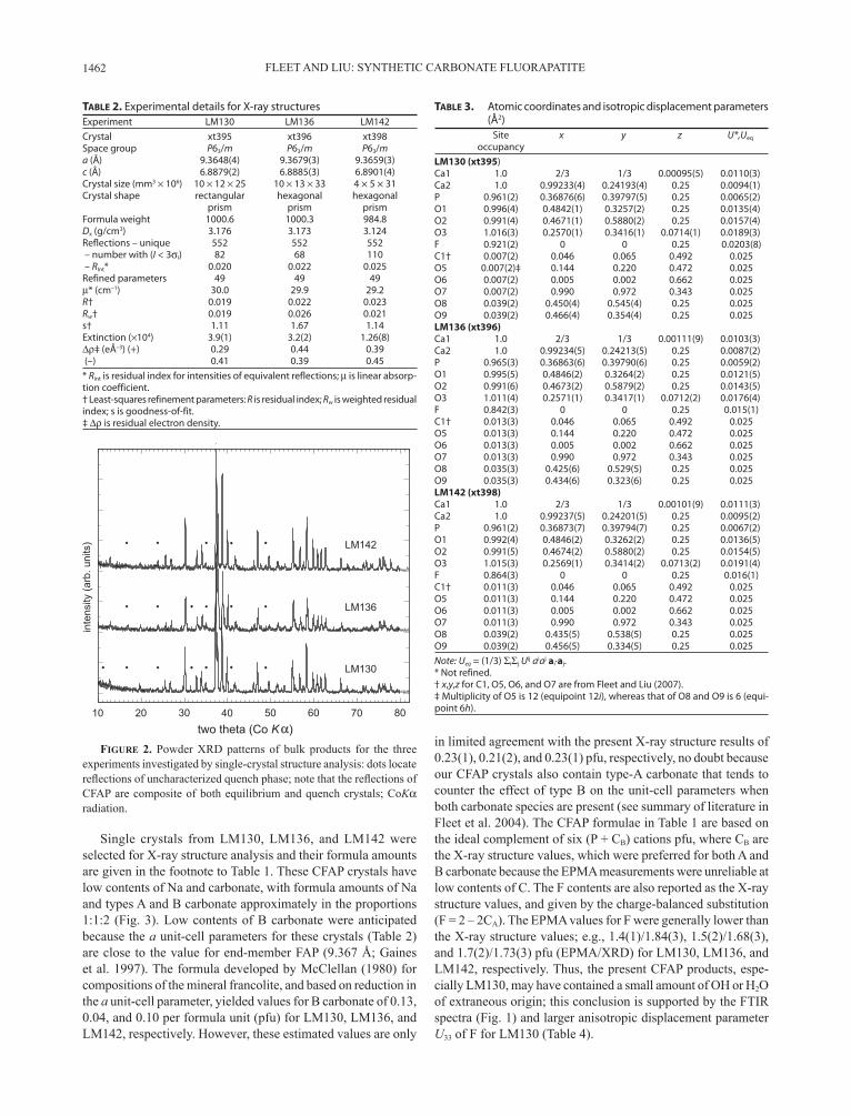
dominated by Na- and carbonate-bearing CFAP with minor amounts of other quench phases. CFAP was present in two grain sizes, as larger prismatic crystals up to 200 µm in length and as a fine-grained matrix. Experiments LM134, LM130, and LM142 produced sufficiently large crystals for study by FTIR spectroscopy (Fig. 1). There were insufficient experiments for detailed phase relations, but it appeared that the four different bulk compositions were run at above-solidus experimental conditions, with the large crystals representing near-liquidus growth and the fine-grained matrix quench material. This conclusion is consistent with the phase relations in the system CaO-CaF2-P2O5-H2O at 0.1 GPa (Biggar 1967). Powder XRD patterns of the bulk products for the experiments investigated by single-crystal structure analysis (LM130, LM136, and LM142) are reproduced in Figure 2, with reflections of an uncharacter-ized quench phase indicated by dots. Of the two products not investigated by structure analysis, LM133 was essentially pure CFAP but LM134 yielded about 20% of non-apatite phases, which included fluorite, calcite, and the new uncharacterized phase flagged in Figure 2.
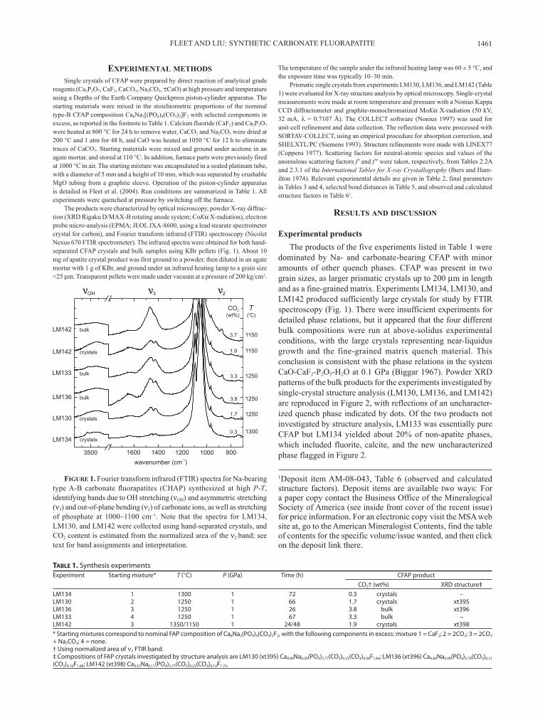
Figure 1. Fourier transform infrared (FTIR) spectra for Na-bearing type A-B carbonate fluorapatites (CHAP) synthesized at high P-T, identifying bands due to OH stretching (νOH) and asymmetric stretching (ν3) and out-of-plane bending (ν2) of carbonate ions, as well as stretching of phosphate at 1000–1100 cm–1. Note that the spectra for LM134, LM130, and LM142 were collected using hand-separated crystals, and CO2 content is estimated from the normalized area of the ν2 band; see text for band assignments and interpretation.
1Deposit item AM-08-043, Table 6 (observed and calculated structure factors). Deposit items are available two ways: For a paper copy contact the Business Office of the Mineralogical Society of America (see inside front cover of the recent issue) for price information. For an electronic copy visit the MSA web site at, go to the American Mineralogist Contents, find the table of contents for the specific volume/issue wanted, and then click on the deposit link there.
Table 1. Synthesis experiments Experiment Starting mixture* T (°C) P (GPa) Time (h) CFAP product CO2† (wt%) XRD structure‡LM134 1 1300 1 72 0.3 crystals –LM130 2 1250 1 66 1.7 crystals xt395LM136 3 1250 1 26 3.8 bulk xt396LM133 4 1250 1 67 3.3 bulk –LM142 3 1350/1150 1 24/48 1.9 crystals xt398* Starting mixtures correspond to nominal FAP composition of Ca8Na2(PO4)4(CO3)2F2, with the following components in excess: mixture 1 = CaF2; 2 = 2CO2; 3 = 2CO2 + Na2CO3; 4 = none. † Using normalized area of ν2 FTIR band. ‡ Compositions of FAP crystals investigated by structure analysis are LM130 (xt395) Ca9.89Na0.09(PO4)5.77(CO3)0.23(CO3)0.08F1.84; LM136 (xt396) Ca9.84Na0.09(PO4)5.79(CO3)0.21
(CO3)0.16F1.68; LM142 (xt398) Ca9.57Na0.11(PO4)5.77(CO3)0.23(CO3)0.14F1.73.
FLEET AND LIU: SyNTHETIC CARBONATE FLUORAPATITE1462
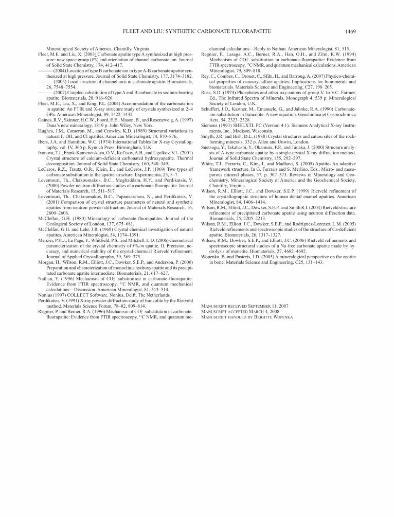
Single crystals from LM130, LM136, and LM142 were selected for X-ray structure analysis and their formula amounts are given in the footnote to Table 1. These CFAP crystals have low contents of Na and carbonate, with formula amounts of Na and types A and B carbonate approximately in the proportions 1:1:2 (Fig. 3). Low contents of B carbonate were anticipated because the a unit-cell parameters for these crystals (Table 2) are close to the value for end-member FAP (9.367 Å; Gaines et al. 1997). The formula developed by McClellan (1980) for compositions of the mineral francolite, and based on reduction in the a unit-cell parameter, yielded values for B carbonate of 0.13, 0.04, and 0.10 per formula unit (pfu) for LM130, LM136, and LM142, respectively. However, these estimated values are only
in limited agreement with the present X-ray structure results of 0.23(1), 0.21(2), and 0.23(1) pfu, respectively, no doubt because our CFAP crystals also contain type-A carbonate that tends to counter the effect of type B on the unit-cell parameters when both carbonate species are present (see summary of literature in Fleet et al. 2004). The CFAP formulae in Table 1 are based on the ideal complement of six (P + CB) cations pfu, where CB are the X-ray structure values, which were preferred for both A and B carbonate because the EPMA measurements were unreliable at low contents of C. The F contents are also reported as the X-ray structure values, and given by the charge-balanced substitution (F = 2 – 2CA). The EPMA values for F were generally lower than the X-ray structure values; e.g., 1.4(1)/1.84(3), 1.5(2)/1.68(3), and 1.7(2)/1.73(3) pfu (EPMA/XRD) for LM130, LM136, and LM142, respectively. Thus, the present CFAP products, espe-cially LM130, may have contained a small amount of OH or H2O of extraneous origin; this conclusion is supported by the FTIR spectra (Fig. 1) and larger anisotropic displacement parameter U33 of F for LM130 (Table 4).
Table 2. Experimental details for X-ray structuresExperiment LM130 LM136 LM142Crystal xt395 xt396 xt398Space group P63/m P63/m P63/ma (Å) 9.3648(4) 9.3679(3) 9.3659(3)c (Å) 6.8879(2) 6.8885(3) 6.8901(4)Crystal size (mm3 × 106) 10 × 12 × 25 10 × 13 × 33 4 × 5 × 31Crystal shape rectangular hexagonal hexagonal prism prism prismFormula weight 1000.6 1000.3 984.8Dx (g/cm3) 3.176 3.173 3.124Reflections – unique 552 552 552 – number with (I < 3σI) 82 68 110 – RInt* 0.020 0.022 0.025Refined parameters 49 49 49µ* (cm–1) 30.0 29.9 29.2R† 0.019 0.022 0.023Rw† 0.019 0.026 0.021s† 1.11 1.67 1.14Extinction (×104) 3.9(1) 3.2(2) 1.26(8)∆ρ‡ (eÅ–3) (+) 0.29 0.44 0.39 (–) 0.41 0.39 0.45* Rint is residual index for intensities of equivalent reflections; µ is linear absorp-tion coefficient. † Least-squares refinement parameters: R is residual index; Rw is weighted residual index; s is goodness-of-fit. ‡ ∆ρ is residual electron density.
Table 3. Atomic coordinates and isotropic displacement parameters (Å2)
Site x y z U*,Ueq
occupancyLM130 (xt395)Ca1 1.0 2/3 1/3 0.00095(5) 0.0110(3)Ca2 1.0 0.99233(4) 0.24193(4) 0.25 0.0094(1)P 0.961(2) 0.36876(6) 0.39797(5) 0.25 0.0065(2)O1 0.996(4) 0.4842(1) 0.3257(2) 0.25 0.0135(4)O2 0.991(4) 0.4671(1) 0.5880(2) 0.25 0.0157(4)O3 1.016(3) 0.2570(1) 0.3416(1) 0.0714(1) 0.0189(3)F 0.921(2) 0 0 0.25 0.0203(8)C1† 0.007(2) 0.046 0.065 0.492 0.025O5 0.007(2)‡ 0.144 0.220 0.472 0.025O6 0.007(2) 0.005 0.002 0.662 0.025O7 0.007(2) 0.990 0.972 0.343 0.025O8 0.039(2) 0.450(4) 0.545(4) 0.25 0.025O9 0.039(2) 0.466(4) 0.354(4) 0.25 0.025LM136 (xt396)Ca1 1.0 2/3 1/3 0.00111(9) 0.0103(3)Ca2 1.0 0.99234(5) 0.24213(5) 0.25 0.0087(2)P 0.965(3) 0.36863(6) 0.39790(6) 0.25 0.0059(2)O1 0.995(5) 0.4846(2) 0.3264(2) 0.25 0.0121(5)O2 0.991(6) 0.4673(2) 0.5879(2) 0.25 0.0143(5)O3 1.011(4) 0.2571(1) 0.3417(1) 0.0712(2) 0.0176(4)F 0.842(3) 0 0 0.25 0.015(1)C1† 0.013(3) 0.046 0.065 0.492 0.025O5 0.013(3) 0.144 0.220 0.472 0.025O6 0.013(3) 0.005 0.002 0.662 0.025O7 0.013(3) 0.990 0.972 0.343 0.025O8 0.035(3) 0.425(6) 0.529(5) 0.25 0.025O9 0.035(3) 0.434(6) 0.323(6) 0.25 0.025LM142 (xt398)Ca1 1.0 2/3 1/3 0.00101(9) 0.0111(3)Ca2 1.0 0.99237(5) 0.24201(5) 0.25 0.0095(2)P 0.961(2) 0.36873(7) 0.39794(7) 0.25 0.0067(2)O1 0.992(4) 0.4846(2) 0.3262(2) 0.25 0.0136(5)O2 0.991(5) 0.4674(2) 0.5880(2) 0.25 0.0154(5)O3 1.015(3) 0.2569(1) 0.3414(2) 0.0713(2) 0.0191(4)F 0.864(3) 0 0 0.25 0.016(1)C1† 0.011(3) 0.046 0.065 0.492 0.025O5 0.011(3) 0.144 0.220 0.472 0.025O6 0.011(3) 0.005 0.002 0.662 0.025O7 0.011(3) 0.990 0.972 0.343 0.025O8 0.039(2) 0.435(5) 0.538(5) 0.25 0.025O9 0.039(2) 0.456(5) 0.334(5) 0.25 0.025Note: Ueq = (1/3) ΣiΣj Uij aiaj ai·aj.* Not refined. † x,y,z for C1, O5, O6, and O7 are from Fleet and Liu (2007). ‡ Multiplicity of O5 is 12 (equipoint 12i), whereas that of O8 and O9 is 6 (equi-point 6h).
Figure 2. Powder XRD patterns of bulk products for the three experiments investigated by single-crystal structure analysis: dots locate reflections of uncharacterized quench phase; note that the reflections of CFAP are composite of both equilibrium and quench crystals; CoKα radiation.

FLEET AND LIU: SyNTHETIC CARBONATE FLUORAPATITE 1463
FTIR spectroscopyThe FTIR spectra (Fig. 1) are dominated by a complex band
at about 1000–1100 cm–1 for the asymmetric stretch vibration of the phosphate group. In addition, they reveal a weak band for the stretch vibration of structurally bound OH at 3537 cm–1, very broad bands for molecular water at about 3300–3600 (OH stretch) and 1600–1700 cm–1 (H2O in-plane bend), and bands for carbonate at 1400–1500 cm–1 (asymmetric stretch vibration; ν3) and 873–880 cm–1 (out-of-plane bend vibration; ν2). The structur-ally bound OH vibration is at a significantly lower wavenumber in CFAP than in HAP or CHAP [e.g., 3573 cm–1, Ross (1974); 3570 cm–1, Wilson et al. (2005); 3571 cm–1, Fleet et al. (2004); and 3572 cm–1, Fleet and Liu (2007)]. This difference appears to be consistent with the downward shift to 3546 cm–1 due to the interaction between OH and F in mixed hydroxyl-fluorapatites (Ross 1974), although Regnier et al. (1994) reported a faint band for a trace amount of hydroxyl in FAP at 3570 cm–1, which is essentially unchanged from the position of the OH band in end-member HAP.
Interpretation of the ν3 carbonate band in the FTIR spectra of apatites with multiple carbonate species is complicated by band overlap and asymmetry of the doublet for the channel (type A) carbonate species (e.g., Fleet et al. 2004). Band overlap in the 1470–1450 cm–1 interval is particularly troublesome. Earlier stud-ies on natural and synthetic CHAP (e.g., Bonel 1972; LeGeros et al. 1969; Elliott 1964, 2002; Fleet et al. 2004) found that type A carbonate was characterized by a doublet band at about 1545 and 1460–1450 cm–1 (ν3) and a singlet band at about 878 cm–1 (ν2), whereas type-B carbonate has these bands at about 1450–1455, 1410–1420, and 873 cm–1, respectively. However, Fleet and Liu (2007) found recently that, in synthetic Na-bearing CHAP, the ν3 doublet for type-A carbonate is apparently shifted to lower wavenumbers into the region normally associated with type-B
carbonate. The present spectra for the large Na-bearing CFAP crystals have the same overall form in the ν3 region as the CHAP spectra of Fleet and Liu (2007) with resolved bands at 1418, 1452, and 1463 cm–1, but the high-wavenumber components are weaker, consistent with more type-B carbonate than type A. This conclusion is reinforced by the appearance of the compound band for the out-of-plane bend vibration (ν2), which has a dominant component at 873 cm–1 (type B carbonate) and a weak shoulder at 880 cm–1 (type A; Fig. 1). The separate contributions of type-B and -A carbonate to the ν2 bands have been quantified using fitted spectra. The area ratio B/A is indeed greater than unity and in good agreement with the corresponding X-ray structure results for all three crystals studied (Table 7; note that the bulk FTIR spectrum has been used for LM136). In comparison, the ratios for B and A carbonate in Na-bearing CHAP (sample LM005; Fleet and Liu 2007) are 0.9 for the ν2 band areas and 0.8 for the X-ray structure.
Table 4. Comparison of anisotropic displacement parameters (Å2) Position Sample U11 U22 U33 U12 U13 U23 Ca1 LM130 0.0129(3) 0.0129(3) 0.0073(2) 0.0065(3) – – LM136 0.0124(3) 0.0124(3) 0.0062(4) 0.0062(3) – – LM142 0.0133(3) 0.0133(3) 0.0069(3) 0.0066(3) – – HCC* 0.0132(2) 0.0132(2) 0.0079(2) 0.0066(2) – –Ca2 LM130 0.0091(2) 0.0099(2) 0.0091(2) 0.0045(2) – – LM136 0.0085(2) 0.0095(3) 0.0078(3) 0.0044(2) – – LM142 0.0097(2) 0.0105(2) 0.0082(3) 0.0049(2) – – HCC 0.0086(2) 0.0121(2) 0.0081(2) 0.0050(2) – –P LM130 0.0063(3) 0.0071(3) 0.0066(3) 0.0036(2) – – LM136 0.0057(3) 0.0064(3) 0.0058(4) 0.0032(2) – – LM142 0.0067(3) 0.0071(3) 0.0065(4) 0.0036(2) – – HCC 0.0070(2) 0.0078(2) 0.0077(2) 0.0042(2) – –O1 LM130 0.0149(7) 0.0165(7) 0.0145(7) 0.0119(6) – – LM136 0.0116(8) 0.0163(9) 0.013(1) 0.0101(7) – – LM142 0.0151(9) 0.0171(9) 0.014(1) 0.0123(7) – – HCC 0.0124(7) 0.0148(7) 0.013(1) 0.0089(5) – –O2 LM130 0.0129(7) 0.0096(7) 0.0239(7) 0.0052(6) – – LM136 0.0116(8) 0.0081(8) 0.022(1) 0.0042(6) – – LM142 0.0136(9) 0.0102(9) 0.022(1) 0.0057(7) – – HCC 0.0128(7) 0.0101(7) 0.021(1) 0.0047(5) – –O3 LM130 0.0162(5) 0.0295(6) 0.0149(5) 0.0144(5) –0.0043(4) –0.0078(4) LM136 0.0155(6) 0.0290(7) 0.0124(7) 0.0142(5) –0.0050(5) –0.0083(6) LM142 0.0165(6) 0.0297(7) 0.0144(8) 0.0140(6) –0.0042(5) –0.0078(6) HCC 0.0144(7) 0.0258(7) 0.0132(7) 0.0128(4) –0.0045(7) –0.0070(7)F LM130 0.011(1) 0.011(1) 0.039(1) 0.006(1) – – LM136 0.008(1) 0.008(1) 0.029(2) 0.004(1) – – LM142 0.010(1) 0.010(1) 0.028(2) 0.005(1) – – HCC 0.010(1) 0.010(1) 0.053(2) 0.005(1) – –* HCC is fluorapatite from Durango, Mexico (Hughes et al. 1989).
Table 5. Selected bond distances (Å) LM130 (xt395) LM136 (xt396) LM142 (xt398) Ca1-O1 × 3 2.3971(9) 2.396(1) 2.396(1)Ca1-O2a × 3 2.4539(9) 2.457(1) 2.457(1)Ca1-O3a × 3 2.802(1) 2.802(1) 2.804(1)Mean 2.551 2.552 2.552 Ca2-O1b 2.675(1) 2.680(2) 2.680(2)Ca2-O2c 2.365(1) 2.363(1) 2.362(2)Ca2-O3d × 2 2.4927(9) 2.495(1) 2.493(1)Ca2-O3e × 2 2.3543(8) 2.353(1) 2.353(1)Mean 2.456 2.456 2.456Ca2-F 2.3024(4) 2.3050(4) 2.3032(4) P-O1 1.536(1) 1.535(2) 1.536(2)P-O2 1.542(1) 1.542(2) 1.542(2)P-O3 × 2 1.5278(9) 1.528(1) 1.530(1)Mean 1.533 1.533 1.534 Note: a = 1 – x, 1 – y, –z; b = 1 – y, x – y, z; c = 1 – x + y, 1 – x, z; d = 1 + x, y, z; e = 1 + x – y, x, –z.

FLEET AND LIU: SyNTHETIC CARBONATE FLUORAPATITE1464
The FTIR band areas of the carbonate vibration modes are consistently higher for bulk samples than for crystal samples (Fig. 1), showing that more carbonate is incorporated in quench CFAP than in CFAP grown under equilibrium conditions. The individual components of the ν3 carbonate band of LM142 are partially resolved in the bulk sample spectrum, and yield mea-sured positions of 1417, 1452, 1467, and 1508 cm–1. Interestingly, this ν3 band is similar in appearance to the ν3 band in the FTIR spectrum of LM005, the CHAP crystal sample with the highest total carbonate content in Fleet and Liu (2007): the resolved components for the LM005 spectrum are at 1415, 1452, 1469, and 1506 cm–1. The ratio of the areas of the B and A contributions to the ν2 band in the bulk spectrum of LM142 is 1.5, showing that the proportion of A and B carbonate in the bulk sample is essentially the same as that of the coexisting crystal, which has a ratio of 1.6 (Table 7).
The FTIR spectra also show that the uptake of carbonate is significantly lower in Na-bearing CFAP than in the Na-bearing CHAP synthesized in Fleet and Liu (2007), for broadly similar experimental conditions. Total (A + B) carbonate contents for the CFAP products have been estimated from ν3 and ν2 band areas,
normalized against the O-P-O bending mode band (at about 600–650 cm–1) and calibrated against the CHAP crystal sample from experiment LM005 in Fleet and Liu (2007), which had a CO2 content of 8.2 wt%. Where comparisons can be made (i.e., for LM130 and LM142), estimates using the ν2 band are in good agreement with the X-ray structure results (Table 7) but the CO2 contents obtained using the ν3 band are consistently too high by a factor of about 1.4.
X-ray structuresThe X-ray structure refinements using single crystals from
experiments LM130, LM136, and LM142 generally followed previous studies (Fleet and Liu 2004, 2007; Fleet et al. 2004). Preliminary refinements starting with ideal FAP stoichiometry resulted in three structures very close to that of end-member and near-end-member FAP (e.g., Hughes et al. 1989), in terms of occupancy, and positional and thermal parameters. Weak peaks in residual electron density maps located O atoms of the carbonate ions in the apatite channel (type A) and in the vicin-ity of the phosphate group (type B). Various constraints were added to promote convergence of the structure refinements, as detailed in Table 3, because the electron densities of atoms of the A and B carbonate ions were close to background amounts. The scattering factors and dispersion corrections for the Ca1 and Ca2 positions were weighted in proportion to the formula amounts of Ca and Na given in Table 1. The structure refinements confirmed that Ca1 and Ca2 were essentially fully occupied by (Ca + Na), but refinement of the individual site occupancies was ambiguous due to the minor content of Na and vacancies. Therefore, Ca1 and Ca2 occupancies were fixed at 1.0, with the small proportion of large-cation-site vacancies being ignored. On the other hand, the occupancy of P was somewhat less than unity, consistent with substitution of the phosphate group by the type B carbonate ion (e.g., Wilson et al. 1999; Morgan et al. 2000; Leventouri et al. 2000). The atom positions of the channel (type A) carbonate ion (C1, O5, O6, and O7) were taken from the CHAP structure of sample LM005 in Fleet and Liu (2007), and were not further refined. The oxygen O5, which was furthest away from the c-axis and least affected by the presence of the dominant fluoride anion in the apatite channel, was used for the occupancy refinement. Also, for all three crystals investigated, the residual electron density peaks consistent with C1 and O5
Figure 3. Correlation of Na and A and B carbonate in carbonate-bearing hydroxylapatite (CHAP = open squares; Fleet and Liu 2007) and fluorapatite (CFAP = filled squares; this study), consistent with local coupling of substituents: formula amounts approximate to Na = A = B in CHAP and Na = A = B/2 in CFAP.
Table 7. O-O distances and carbonate ion contents Carbonate content/ O-O distance LM130 LM136 LM142Total carbonate content (CO2; wt%) X-ray structure 1.4 1.6 1.6FTIR (ν2 band area) 1.7 – 1.9Contents of carbonate O atoms (pfu) O5 (A carbonate) 0.08(3) 0.16(3) 0.14(3)O8,O9 (B carbonate) 0.23(1) 0.21(2) 0.23(1)Ratio of B carbonate to A carbonate (B/A) X-ray structure 2.9 1.3 1.6FTIR (ν2 band areas) 2.6 1.2* 1.5O-O distances for possible B carbonate ions (Å)† Single B carbonateO9-O8 1.87(6) 1.97(8) 2.02(7)O8-O3 2.23(2) 2.08(3) 2.15(3)O3-O9 2.27(4) 2.14(5) 2.27(4)B1 carbonateO8-O3 2.23(2) 2.08(3) 2.15(3)O3-O1 2.526(1) 2.527(2) 2.528(2)O1-O8 2.23(5) 2.23(6) 2.25(5)B2 carbonateO9-O2 2.19(4) 2.34(6) 2.33(5)O2-O3 2.484(1) 2.484(2) 2.487(2)O3-O9 2.27(4) 2.14(5) 2.27(4)* Ratio for bulk spectrum. † Carbonate ion O-O in calcite is 2.219 Å (Smyth and Bish 1988).

FLEET AND LIU: SyNTHETIC CARBONATE FLUORAPATITE 1465
were present in difference Fourier maps compiled after refine-ment of the structure with ideal FAP stoichiometry. Finally, the occupancies of the two resolved B carbonate O atoms (O8 and O9) were constrained according to: O8 = O9 = (6 – P), as in Fleet and Liu (2007).
The three crystals investigated were of high diffraction qual-ity and yielded essentially the same ideal FAP structure (Tables 3 to 5). With the exception of the F occupancies, the values for each of the variable parameters agree within three standard deviations. This agreement is remarkable in light of the quite different size and shape of the crystals (Table 2). There is also good agreement with the refined structure of natural fluorapatite from Durango, Mexico (Hughes et al. 1989). This similarity even extends to the anisotropic displacement parameters (Table 4), which are generally the most sensitive to errors associated with poor crystal quality, crystal setting, absorption, and extinction correction, etc. The natural product does have larger unit-cell parameters and interatomic distances but these reflect the 8 mol% substitution by chlorapatite. The electron densities of the carbonate O atoms in the present structures were equivalent to only about 0.1 and 0.3 of an H atom for types A and B carbon-ate ions, respectively. Resolution of these very weak electron density features in close proximity to F and O atoms of the host FAP structure is attributable entirely to the high quality of the present X-ray structure refinements.
Within the apatite channel, O6 and O7 were too close to the fluoride anion on the c-axis at z = ¼, ¾ for meaningful inde-pendent refinement of their weak electron densities. Also, the C atom electron density was both weak and diffuse because the A carbonate ion is disordered within the ideal FAP structure of the host apatite with a multiplicity of twelve, and because the C atoms (C1; Table 3) of the twelve orientations overlap near 0,0,0 and 0,0,½. Fortunately, O5 is located off the c axis (Figs. 4 and 5) and its refined occupancy does establish the presence and amount of type-A carbonate in the three structures, even though the precise position and orientation of the carbonate ion are indeterminate. The total formula amount of type-A car-bonate is given by the product (O site-occupancy × 12), and is 0.08(3), 0.16(3), and 0.14(3) for LM130, LM136, and LM142, respectively (Table 7).
In residual electron density maps for the ideal FAP structure of the host apatite, the two strongest peaks and the only O atom positions in the vicinity of the phosphate group that could be attributed to partial replacement by carbonate gave rise to O8 and O9, each with a multiplicity of six (Table 1). Their refined occupancies (Table 3) are equivalent to about 0.23 B carbonate ions pfu; i.e., approximately twice the contents of A carbonate. Electron density consistent with the B carbon atom was present but too diffuse and weak for meaningful refinement. The new O atoms (O8 and O9) can be associated with either one or two non-equivalent B carbonate ions pfu oriented closely parallel to the sloping faces of the substituted phosphate group and defined by the O atoms O8-O9-O3 for a single-B carbonate ion and O8-O3-O1 and O9-O2-O3 for two non-equivalent B carbonate ions, labeled B1 and B2, respectively (Table 7). The structure with the single-B carbonate ion is preferred based on the satisfactory agreement of the O-O distances with that for the ideal carbonate ion geometry (e.g., 2.219 Å in calcite; Smyth
and Bish 1988) and consistency with previous X-ray structure studies on type A-B CHAP (e.g., Fleet and Liu 2004, 2007; Fleet et al. 2004). Discrepancies with the ideal O-O distance represent errors in locating atom positions in structures determined at the lower limit of resolution of the X-ray structure method using conventional laboratory equipment and do not imply that the carbonate ion geometries in CFAP are anomalously distorted. The O-O distances for the structure with two non-equivalent B carbonate ions also show good agreement with the ideal distance (Table 7), taking into account that the long O3-O1 and O2-O3 distances for B1 and B2, respectively, could indicate that the electron densities of the second and third (unresolved) O atoms are buried within the electron densities of O1/O2 and O3 in the average structure. In fact, it is the overlap (or partial overlap) of carbonate and phosphate O atoms that has made precise location of the B carbonate ion in apatite so difficult in previous studies. However, the site occupancies for this alternative structure have to be one-half of the values for the single B carbonate structure and, also, a crystal-chemical explanation for the presence of two non-equivalent B carbonate ions is not readily apparent.
Figure 4. Fragment of structures of (a) carbonate-bearing hydroxylapatite (CHAP; Fleet and Liu 2007) and (b) CFAP, showing location of B carbonate ion close to the sloping faces of the substituted phosphate tetrahedron: multiplicities due to P63/m symmetry of the host apatite structures are not shown. Note that the symmetry-related O3 is removed to avoid short interaction with O5 of the type A carbonate ion: elevation view; interatomic distances are Å.
Figure 5. Fragment of the structure of CFAP viewed in c-axis projection, detailing spatial relationships of A and B carbonate ions and charge-compensating Na cation: interatomic distances are Å.

FLEET AND LIU: SyNTHETIC CARBONATE FLUORAPATITE1466
Accommodation of B carbonate ionThe present high-pressure synthesized crystals are Na-
bearing, type A-B carbonate fluorapatites with compositions analogous to those of Na-bearing CHAP (Fleet and Liu 2007), but with approximately twice as much B carbonate as A. For the CHAP crystals, Na and types A and B carbonate were present in approximately equal amounts, consistent with a substitution formula of Ca10–yNay[(PO4)6–y(CO3)y][(OH)2–2x(CO3)x], with x ≈ y ≤ 1.0, and an idealized substitution scheme for B carbonate of:
[Na + (BCO3) = Ca + (PO4)]. (1)
For the present CFAP crystals, the substitution formula ap-pears to be Ca10–1.5yNayn0.5y[(PO4)6–2y(CO3)2y][F2–2x(CO3)x], with x ≈ y ≈ 0.1, and an overall idealized substitution scheme for B carbonate of:
[Na + 0.5n + 2(BCO3) = 1.5Ca + 2(PO4)]. (2)
The small fraction of large-cation site vacancies (represented by n in Eq. 2) is undetectable by present methods and has been ignored in reporting crystal compositions in Table 1. The cor-relation of Na with B and A carbonate in CHAP and with B/2 and A in CFAP (Fig. 3) confirms that Na has an active role in the substitution of carbonate into these apatites.
Fleet and Liu (2007) concluded that the introduction of Na and A and B carbonate into HAP is coupled by charge balance and spatial accommodation requirements. Sodium is the principal charge-balancing agent and the bulky channel carbonate ion, with its protruding off-axis O atom (O5; Fig. 4a), uses some of the space created in the carbonate-for-phosphate substitution. Thus, the Na cation and A and B carbonate ions are present as randomly distributed defect clusters within the host apatite structure. The B carbonate ion in Na-bearing CHAP is located near the sloping faces of the substituted phosphate group, but inclined at an angle of 53° to the mirror plane; i.e., it is tilted 18° away from the space of the phosphate tetrahedron). One of the O3 O atoms of the phosphate group is displaced to O8 and the second, symmetry-related O3 is lost to maintain charge bal-ance. The O1 atom is displaced slightly to O9 and the third B carbonate O atom is concealed by the electron density of O2. For the crystal from experiment LM005 of Fleet and Liu (2007), the O-O distances are O8-O9 = 2.38, O9-O2 = 2.33, and O2-O8 = 1.92 Å and the apatite channel site is fully occupied by carbon-ate. In the absence of a proximal B carbonate ion, the off-axis O atom (O5) of the channel carbonate would be only 1.14 Å from an O3 of the phosphate group. Displacement of O3 to O8 extends this distance to 2.01 C, which is still too short for an O-O distance between two different strongly bonded structural units. Therefore, in the preferred configuration (Fig. 4a), the O3 atom in question is removed entirely from the structure. Logi-cally, charge balance requirements favor placing the Na cation closest to this vacant O3 site.
The accommodation of the B carbonate ion in CFAP (Figs. 4b and 5) is analogous to that in CHAP. The B carbonate ion is now more closely parallel to the sloping faces of the substituted phosphate groups, being inclined into the space of the phos-phate tetrahedron at an angle of only 3.5°. Its oxygen cluster is
formed from the O3 atom most distant from O5 of the channel carbonate, O8 by displacement of O2, and O9 by displacement of O1, with O-O distances given in Table 7. Differences with the accommodation of B carbonate in CHAP are related to the stron-ger bonding within the apatite channel of FAP and consequent limited substitution by carbonate. The four substituents—Na cation, large-cation vacancy, and A and B carbonate ions—are most probably present as a single defect cluster, as suggested by substitution Equation 2. Alternatively, in view of the decrease in the importance of type-A carbonate, there might be two types of defect clusters in these CFAP crystals; the coupled Na + A + B carbonate cluster described above, and an independent cluster consisting of a large-cation vacancy coupled to two B carbonate ions. This revision would require modification of the substitution formula to Ca10–y+zNayn0.5z[(PO4)6–(y+z)(CO3)y+z][F2–2x(CO3)x], with x ≈ y ≈ z ≈ 0.1, and with substitution schemes for B carbonate of:
[Na + (BCO3) = Ca + (PO4)] (3)
for the y stoichiometric coefficient, and
[n + 2(BCO3) = Ca + 2(PO4)] (4)
for the z coefficient. Note that the Ca1 and Ca2 site occupancies of Na in these carbonate-bearing apatites have not been deter-mined, although the presently described models for CHAP and CFAP (Fig. 4) have placed them at the Ca2 site.
Francolite
The present CFAP crystals are the products of high-tempera-ture and -pressure synthesis and seemingly distinct from franco-lite, the variety of carbonate-fluorapatite with excess F and the principal phosphate mineral in sedimentary phosphorites (Mc-Clellan and Lehr 1969; McClellan 1980; Schuffert et al. 1990; Regnier et al. 1994). Francolite is characterized by an excess amount of F, but the structural accommodation of this feature remains unclear due to the fine grain size of francolite crystals. As emphasized in McClellan (1980) and this study, structural studies on carbonate apatite are frustrated by the overall inverse correlation between crystal size and carbonate content. Francolite and low-temperature, laboratory synthesized apatites contain sufficient carbonate to resolve structural details by single-crystal XRD, but their crystals are generally sub-micrometer in size and of poor quality. On the other hand, relatively large apatite crystals may be grown at high temperature and pressure, under equilibrium conditions above the carbonate-apatite solidus, but their carbonate contents are low. Also, our various attempts at growing suitably sized crystals of CFAP, CHAP, and carbonate-bearing chlorapatite by hydrothermal synthesis at intermediate temperatures have been uniformly unsuccessful.
It has been known for some time that the B carbonate con-tent of francolite is more-or-less proportional to the amount of excess F; e.g., McClellan (1980) used the relationship B = 0.4Fx, where Fx is excess F, in calculating the theoretical francolite compositions in phosphate rocks from various localities. This interesting aspect of the complex crystal chemistry of francolite has been discussed at length, especially following the proposal

FLEET AND LIU: SyNTHETIC CARBONATE FLUORAPATITE 1467
of Bornemann-Starinkevitch (1938) that the B carbonate and excess fluorine were present as the (CO3·F)3– ion that substituted directly for the phosphate group (e.g., McClellan 1980; Regnier et al. 1994; Nathan 1996; Regnier and Berner 1996). Although continuation of this discussion is beyond the scope of this pa-per, we should point out that the perfect curvilinear correlation between excess F and total carbonate reported in Nathan (1996) is just an artifact of the assumptions made by McClellan (1980) in deriving his model compositions.
We did not expect to see any evidence of excess F in the present CFAP crystals because the F contents were <2 pfu and the crystals were high-temperature products. However, differ-ence Fourier maps for LM142 revealed a weak residual electron density peak at x = –0.213, y = 0.174, and z = 0.5 (equipoint 12i), which was present after both refinement of the ideal FAP structure of the host apatite and the final refinement reported in Table 3. This residual peak is in near equilateral triangular coordination with one Ca1 and two Ca2 cations, giving inter-atomic distances and bond angles (~2.28, 2.32, 2.42 Å and 123, 115, 122°, respectively) similar to those of the channel fluoride anion (2.303 Å, 120°; Table 5). Therefore, it is tentatively as-signed to a minor-trace amount of excess fluorine (Fig. 6). The occupancy of the new site (labeled Fx) in LM142 has been refined by iteration, giving a value of 0.0044(1) or 0.053(1) pfu. The Fx atom has to be located adjacent to a B carbonate ion to avoid a prohibitively close Fx-O3 distance of 1.2 Å. Thus, possible substitution schemes are
[Fx + CO3 = PO4] (5)
and,
[Na + F + 2CO3 = Ca + 2PO4]. (6)
The presently determined location and orientation of the B carbonate ion in CFAP crystallized at high temperature and pres-sure is at variance with the conclusion of Leventouri et al. (2000, 2001) and Antonakos et al. (2007), who proposed that it was located on the (horizontal) mirror plane, with O atoms at O1, O2, and a third location mid-way between the two symmetry related O3 atoms of the substituted phosphate group. Their conclusions were based on a Rietveld neutron powder diffraction study of francolite from Epirus, Greece and its heat-treated products, as well as shifts in the ν3c asymmetric stretching band of phosphate and lattice dynamics calculations. The structure refinements did not yield direct evidence of the B carbonate ion, but there was indirect evidence from systematic changes in anisotropic displacement parameters as a function of temperature and in P-O bond lengths for the average structure, in that P-O1 and P-O2 decreased with substitution of phosphate by carbonate and P-O3 increased. The P-O distances for the present CFAP crystals do not show this trend; rather, P-O2 and P-O3 actually increase and decrease, respectively, relative to Durango fluorapatite (Hughes et al. 1989). Also, residual electron density consistent with the third carbonate O atom on the mirror plane was absent in both this study and Leventouri et al. (2000). It is well known that O atom positions are determined with poor precision in conventional Rietveld powder structure refinement of apatites (e.g., White
et al. 2005; Mercier et al. 2006). The present study emphasizes the unique advantage of single-crystal diffraction methods in locating weak electron densities.
The pertinent experimental observations in Leventouri et al. (2000) and this study however are not significantly discrepant, since both studies found that O1 and O2 are shifted on the mir-ror plane toward the center of the phosphate tetrahedron. The neutron powder diffraction study of Leventouri et al. (2000) sim-ply detected the average position of O1 and O2 in the annealed francolite structure, whereas the present study resolves separate O1/O9 and O2/O8 positions for the phosphate and carbonate O atoms. Substitution by type B carbonate results in observed atom shifts of 0.31 Å for O1 to O9 and 0.41 Å for O2 to O8. When these shifts are weighted by the proportion of type-B carbonate estimated for the Epirus francolite (0.95 pfu), the corresponding apparent shortening of the P-O1 and P-O2 bond lengths in the average structure is calculated to be about 0.05 and 0.06 Å, which compares favorably with about 0.04 and 0.04 Å, respectively, in Leventouri et al. (2000).
Appraisal of X-ray structuresSubstitution of the carbonate ion into apatite is limited in
extent and, unlike atom-for-atom solid solution, introduces new atomic positions. Also, individual substituents (or defect clusters) are disordered within the host structure. The single-crystal XRD pattern represents only the average structure, a composite of the host structure and the carbonate ions, which are randomly distributed throughout crystals but locally ordered in minimum energy locations and configurations. In addition, local displacements of atoms of the host structure occur to ac-
Figure 6. Suggested location of excess fluoride anion (Fx) in high-pressure synthesized CFAP (and authigenic francolite as well) viewed in c-axis projection: Fx lies in the outer wall of the apatite channel and must be adjacent to at least one B carbonate ion to avoid a short interaction with an O3 atom of a phosphate group. Note that the threefold coordination of Fx with Ca2, Ca1 cations is similar to that of the channel fluoride anion with Ca2: interatomic distances are Å.
FLEET AND LIU: SyNTHETIC CARBONATE FLUORAPATITE1468
commodate the carbonate ions, and result in anomalous increase in anisotropic displacement parameters (Leventouri et al. 2000; Fleet et al. 2004). As a result of these problems, X-ray structures of carbonate apatites present numerous challenges in interpre-tation, especially where carbonate contents are very low. In particular, overlap of carbonate and host structure atoms limits the amount of structural information that can be extracted from X-ray structure analysis.
One consequence of this limited structural information is that formal calculation of bond distances using the average CFAP structures reported in Table 3 results in two anomalously short Ca2-O5 distances, of about 2.1 Å for Na-O5 (Fig. 4) and 2.2 Å for Ca-O5. The appropriate interpretation here is that in the actual CFAP crystals about 1–2% of the Ca2 atoms are locally displaced to accommodate A and B carbonate ions. Similarly, formal cal-culation results in an unacceptably short O5-O3 distance of 1.1 Å, but in the actual crystals these O3 positions are vacant (Fig. 4). Because a small proportion of O3 atoms is predicted to be missing, the refined occupancies of O3 might be expected to be marginally less than unity. Instead, the site occupancies of the phosphate O atom positions (O1, O2, and O3) are all marginally greater than anticipated by the present structural interpretation. However, the structures in Table 3 have been refined using neutral atomic species, and do not take into account the effects of covalence and polarizability, which typically result in excess electron density at O atom anion positions.
Resolution and refinement of the very weak electron density associated with A and B carbonate atoms in the present Na-bear-ing CFAP crystals is attributable to the good diffraction quality of the crystals and the high symmetry of the host fluorapatite structure. This statement is supported by the high proportion of reflections with non-zero intensity (80–88%). Also, the excel-lent sample-to-sample reproducibility for structure parameters using crystals of different size and shape excludes significant error from absorption and extinction. Studies on three separate compositional series of carbonate apatite crystals grown in the presence of excess sodium carbonate, including CHAP (Fleet et al. 2007), CFAP (present study), and carbonate chlorapatite (CCLAP; work in progress), have yielded essentially the same environments for the A and B carbonate ions. These studies encompass a wide range in A and B carbonate content, extend-ing from 0.1–0.2 pfu in CFAP, to 0.4 pfu in CCLAP, and up to 1.0 pfu in CHAP. The occupancies of A carbonate in CFAP are based on refinement of the off-axis O atom O5, which, in residual electron density maps at z = 0.0 and 0.5, results in well-resolved residual peaks in the six equivalent positions consistent with the hexagonal symmetry of the host structure. The inferred locations of C1, O6, and O7 follow directly from study of CHAP structures with high contents of carbonate in the apatite channel (Fleet and Liu 2003, 2005, 2007). The refined amounts of A carbonate in Na-bearing CFAP, CCLAP, and CHAP correlate essentially one-to-one with Na content over the whole composition range investigated. This correlation surely confirms that the reported amounts of A carbonate in the present CFAP crystals are real and not artifacts of the refinement procedures.
Interpretation of the location of the B carbonate ion is more problematical. Logically, the B carbonate ion is located in the vicinity of the substituted phosphate group and uses as many
of the phosphate O atom sites as possible. As noted above, the presence of B carbonate is indicated by significant reduction in the occupancy of the P position. Indeed, for apatites with both A and B carbonate, the P occupancy decreases systematically with increase in total carbonate content through the series CFAP, CCLAP, and CHAP. Also, our various studies have failed to de-tect any significant residual electron density in the vicinity of the phosphate group except for that associated with B carbonate lying close to sloping (i.e., inclined to c-axis) faces of the phosphate tetrahedron. In addition, the coupling of A and B carbonate ions requires the omission of one of the two symmetry-related O3 atoms. In summary, the only likely location for the B carbon-ate ion is close to the sloping faces. Of course, this conclusion applies only to apatites with both A and B carbonate. Apatite with only B carbonate has not been studied by the single-crystal X-ray structure method. Fleet and Liu (2003) did investigate an Na-free type-A CHAP and found that, although the A carbonate was shifted slightly in the apatite channel relative to Na-bearing A-B structures, the O5 atom still projected into the channel wall. Since there was no basis for assuming omission of O3 in this case, significant local displacements were required to avoid close contact of the two O atoms. These adjustments were manifest in high values for anisotropic displacement parameters.
acknowledgMentsWe thank three reviewers for helpful comments, Michael Jennings for collection
of the X-ray reflection data, and the Natural Sciences and Engineering Research Council of Canada for financial support.
reFerences citedAntonakos, A., Liarokapis, E., and Leventouri, T. (2007) Micro-Raman and FTIR
studies of synthetic and natural apatites. Biomaterials, 28, 3043–3054.Aparicio, S., Doty, S.B., Camacho, N.P., Paschalis, E.P., Spevak, L., Mendelsohn,
R., and Boskey, A.L. (2002) Optimal methods for processing mineralized tissues for fourier transform infrared microspectroscopy. Calcified Tissue International, 70, 422–429.
Beshah, K., Rey, C., Glimcher, M.J., Schimizu, M., and Griffin, R.G. (1990) Solid state carbon-13 and proton NMR studies of carbonate-containing calcium phosphates and enamel. Journal of Solid State Chemistry, 84, 71–81.
Biggar, G.M. (1967) Apatite compositions and liquidus phase relationships on the join Ca(OH)2-CaF2-Ca3(PO4)2-H2O from 250 to 4000 bars. Mineralogical Magazine, 36, 539–564.
Bonel, G. (1972) Contribution à l’étude de la carbonatation des apatites. I. Synthèse et étude des propriétés physico-chimiques des apatites carbonatées du type A. Annales de Chimie (Paris, France), 7, 65–88.
Bornemann-Starinkevitch, I.D. (1938) On some isomorphic substitutions in apatite. Doklady Akademii Nauk SSSR, 22, 89–92.
Boskey, A.L. (2003) Mineral analysis provides insights into the mechanism of biomineralization. Calcified Tissue International, 72, 533–536.
Bros, R., Carpena, J., Sere, V., and Beltritti, A. (1996) Occurrence of Pu and fis-siogenic REE in hydrothermal apatites from the fossil nuclear reactor 16 at Oklo (Gabon). Radiochimica Acta, 74, 277–282.
Brudevold, F., Gardner, D.E., and Smith, F.A. (1956) Distribution of fluorine in human enamel. Journal of Dental Research, 35, 420–429.
Comodi, P. and Liu, y. (2000) CO3 substitution in apatite: further insight from new crystal-chemical data of Kasekere (Uganda) apatite. European Journal of Mineralogy, 12, 965–974.
Coppens, P. (1977) LINEX77. State University of New york, Buffalo.El Feki, H., Savariault, J.M., Ben Salah, A., and Jemal, M. (2000) Sodium and
carbonate distribution in substituted calcium hydroxyapatite. Solid State Sciences, 2, 577–586.
Elliott, J.C. (1964) The interpretation of the infra-red absorption spectra of some carbonate-containing apatites. In R.W. Fearnhead and M.V. Stack, Eds., Tooth Enamel: Its Composition, Properties, and Fundamental Structure, p. 20–22. John Wright and Sons, Bristol, U.K.
——— (1994) Structure and chemistry of the apatites and other calcium ortho-phosphates, 389 p. Elsevier, Amsterdam.
——— (2002) Calcium phosphate biominerals. In M.J. Kohn, J. Rakovan, and J.M. Hughes, Eds., Phosphates: Geochemical, Geobiological, and Materials Importance, 48, p. 427–453. Reviews in Mineralogy and Geochemistry,
FLEET AND LIU: SyNTHETIC CARBONATE FLUORAPATITE 1469
Mineralogical Society of America, Chantilly, Virginia.Fleet, M.E. and Liu, X. (2003) Carbonate apatite type A synthesized at high pres-
sure: new space group (P3) and orientation of channel carbonate ion. Journal of Solid State Chemistry, 174, 412–417.
——— (2004) Location of type B carbonate ion in type A-B carbonate apatite syn-thesized at high pressure. Journal of Solid State Chemistry, 177, 3174–3182.
——— (2005) Local structure of channel ions in carbonate apatite. Biomaterials, 26, 7548–7554.
——— (2007) Coupled substitution of type A and B carbonate in sodium-bearing apatite. Biomaterials, 28, 916–926.
Fleet, M.E., Liu, X., and King, P.L. (2004) Accommodation of the carbonate ion in apatite: An FTIR and X-ray structure study of crystals synthesized at 2–4 GPa. American Mineralogist, 89, 1422–1432.
Gaines, R.V., Skinner, H.C.W., Foord, E.E., Mason, B., and Rosenzweig, A. (1997) Dana’s new mineralogy, 1819 p. John Wiley, New york.
Hughes, J.M., Cameron, M., and Crowley, K.D. (1989) Structural variations in natural F, OH, and Cl apatites. American Mineralogist, 74, 870–876.
Ibers, J.A. and Hamilton, W.C. (1974) International Tables for X-ray Crystallog-raphy, vol. IV, 366 p. Kynoch Press, Birmingham, U.K.
Ivanova, T.I., Frank-Kamenetskaya, O.V., Kol’tsov, A.B., and Ugolkov, V.L. (2001) Crystal structure of calcium-deficient carbonated hydroxyapatite. Thermal decomposition. Journal of Solid State Chemistry, 160, 340–349.
LeGeros, R.Z., Trautz, O.R., Klein, E., and LeGeros, J.P. (1969) Two types of carbonate substitution in the apatite structure. Experimentia, 25, 5–7.
Leventouri, Th., Chakoumakos, B.C., Moghaddam, H.y., and Perdikatsis, V. (2000) Powder neutron diffraction studies of a carbonate fluorapatite. Journal of Materials Research, 15, 511–517.
Leventouri, Th., Chakoumakos, B.C., Papanearchou, N., and Perdikatsis, V. (2001) Comparison of crystal structure parameters of natural and synthetic apatites from neutron powder diffraction. Journal of Materials Research, 16, 2600–2606.
McClellan, G.H. (1980) Mineralogy of carbonate fluorapatites. Journal of the Geological Society of London, 137, 675–681.
McClellan, G.H. and Lehr, J.R. (1969) Crystal chemical investigation of natural apatites. American Mineralogist, 54, 1374–1391.
Mercier, P.H.J., Le Page, y., Whitfield, P.S., and Mitchell, L.D. (2006) Geometrical parameterization of the crystal chemistry of P63/m apatite. II. Precision, ac-curacy, and numerical stability of the crystal-chemical Rietveld refinement. Journal of Applied Crystallography, 39, 369–375.
Morgan, H., Wilson, R.M., Elliott, J.C., Dowker, S.E.P., and Anderson, P. (2000) Preparation and characterization of monoclinic hydroxyapatite and its precipi-tated carbonate apatite intermediate. Biomaterials, 21, 617–627.
Nathan, y. (1996) Mechanism of CO32– substitution in carbonate-fluorapatite:
Evidence from FTIR spectroscopy, 13C NMR, and quantum mechanical calculations—Discussion. American Mineralogist, 81, 513–514.
Nonius (1997) COLLECT Software. Nonius, Delft, The Netherlands.Perdikatsis, V. (1991) X-ray powder diffraction study of francolite by the Rietveld
method. Materials Science Forum, 78–82, 809–814.Regnier, P. and Berner, R.A. (1996) Mechanism of CO3
2– substitution in carbonate-fluorapatite: Evidence from FTIR spectroscopy, 13C NMR, and quantum me-
chanical calculations—Reply to Nathan. American Mineralogist, 81, 515.Regnier, P., Lasaga, A.C., Berner, R.A., Han, O.H., and Zilm, K.W. (1994)
Mechanism of CO32– substitution in carbonate-fluorapatite: Evidence from
FTIR spectroscopy, 13C NMR, and quantum mechanical calculations. American Mineralogist, 79, 809–818.
Rey, C., Combes, C., Drouet, C., Sfihi, H., and Barroug, A. (2007) Physico-chemi-cal properties of nanocrystalline apatites: Implications for biominerals and biomaterials. Materials Science and Engineering, C27, 198–205.
Ross, S.D. (1974) Phosphates and other oxy-anions of group V. In V.C. Farmer, Ed., The Infrared Spectra of Minerals, Monograph 4, 539 p. Mineralogical Society of London, U.K.
Schuffert, J.D., Kastner, M., Emanuele, G., and Jahnke, R.A. (1990) Carbonate-ion substitution in francolite: A new equation. Geochimica et Cosmochimica Acta, 54, 2323–2328.
Siemens (1993) SHELXTL PC (Version 4.1). Siemens Analytical X-ray Instru-ments, Inc., Madison, Wisconsin.
Smyth, J.R. and Bish, D.L. (1988) Crystal structures and cation sites of the rock-forming minerals, 332 p. Allen and Unwin, London.
Suetsugu, y., Takahashi, y., Okamura, F.P., and Tanaka, J. (2000) Structure analy-sis of A-type carbonate apatite by a single-crystal X-ray diffraction method. Journal of Solid State Chemistry, 155, 292–297.
White, T.J., Ferraris, C., Kim, J., and Madhavi, S. (2005) Apatite- An adaptive framework structure. In G. Ferraris and S. Merlino, Eds., Micro- and meso-porous mineral phases, 57, p. 307–373. Reviews in Mineralogy and Geo-chemistry, Mineralogical Society of America and the Geochemical Society, Chantilly, Virginia.
Wilson, R.M., Elliott, J.C., and Dowker, S.E.P. (1999) Rietveld refinement of the crystallographic structure of human dental enamel apatites. American Mineralogist, 84, 1406–1414.
Wilson, R.M., Elliott, J.C., Dowker, S.E.P., and Smith R.I. (2004) Rietveld structure refinement of precipitated carbonate apatite using neutron diffraction data. Biomaterials, 25, 2205–2213.
Wilson, R.M., Elliott, J.C., Dowker, S.E.P., and Rodriguez-Lorenzo, L.M. (2005) Rietveld refinements and spectroscopic studies of the structure of Ca-deficient apatite. Biomaterials, 26, 1317–1327.
Wilson, R.M., Dowker, S.E.P., and Elliott, J.C. (2006) Rietveld refinements and spectroscopic structural studies of a Na-free carbonate apatite made by hy-drolysis of monetite. Biomaterials, 27, 4682–4692.
Wopenka, B. and Pasteris, J.D. (2005) A mineralogical perspective on the apatite in bone. Materials Science and Engineering, C25, 131–143.
Manuscript received septeMber 11, 2007Manuscript accepted March 4, 2008Manuscript handled by brigitte Wopenka