accuracy and precision of die spacer thickness with
TRANSCRIPT
Marquette Universitye-Publications@Marquette
Master's Theses (2009 -) Dissertations, Theses, and Professional Projects
Accuracy and Precision of Die Spacer Thicknesswith Combined Computer-Aided Design and 3-DPrinting TechnologyLisa HoangMarquette University
Recommended CitationHoang, Lisa, "Accuracy and Precision of Die Spacer Thickness with Combined Computer-Aided Design and 3-D PrintingTechnology" (2014). Master's Theses (2009 -). Paper 245.http://epublications.marquette.edu/theses_open/245
ACCURACY AND PRECISION OF DIE SPACER THICKNESS WITH COMBINED
COMPUTER-AIDED DESIGN AND 3-D PRINTING TECHNOLOGY
by
Lisa Hoang, D.M.D.
A Thesis submitted to the Faculty of the Graduate School,
Marquette University,
In Partial Fulfillment of the Requirements for
the Degree of Master of Science
Milwaukee, Wisconsin
May 2014
ABSTRACT
ACCURACY AND PRECISION OF DIE SPACER THICKNESS WITH COMBINED
COMPUTER-AIDED DESIGN AND 3-D PRINTING TECHNOLOGY
Lisa Hoang, D.M.D.
Marquette University, 2014
Purpose: The purpose of this study was to evaluate the accuracy and precision of
die-spacer thickness achieved by the combination of computer aided design and 3-
dimension printing technology.
Materials and Methods: An ivorine maxillary central incisor was prepared for
an all ceramic crown. The prepared tooth was duplicated by using poly (vinyl siloxane)
duplicating silicone and 80 die-stone models were produced using type IV dental stone.
Dies were randomly divided into 5 groups with assigned die spacer thickness of (25 µm,
45 µm, 65 µm, 85 µm, 105 µm) (n=16/group). The printed resin copings, obtained from
3D Systems ProJet DP 3000 printer, were cemented onto their respective die-stone
models with Relyx Unicem 2 and stored at room temperature until sectioning into two
halves, in the bucco-lingual direction. The internal gap was measured at 5 defined
locations per side of the sectioned die: (A) facial chamfer, (B) facial mid-axial, (C)
incisal, (D) lingual mid-axial, and lingual (E) chamfer. Images of the printed resin
coping/die-stone model internal gap dimension were obtained with an inverted bright
field metallurgical microscope at 100x magnification. The acquired digital image was
calibrated and measurements were made using image analysis software. The results were
compared using the mixed models ANOVA with repeated measurements to analyze the
paired data and the level of significance was set at .05. The coefficients of variation (CV)
were obtained by standard deviation divided by the mean and multiplied by 100.
Results: The accuracy expressed in term of mean differences between prescribed
die spacer thickness and measured internal gap width (standard deviation) were 50 µm
(10) for the 25 µm group simulated die-spacer thickness, 30 µm (11) for the 45 µm
group, 15 µm (14) for the 65 µm group, 3 µm (24) for the 85 µm group, and - 10 µm (32)
for the 105 µm group. The precision mean of the measurements, expressed in
percentages, ranged between 14 - 33% per the groups.
Conclusions: The accuracy of die spacer thickness showed statistically
significant difference for all the groups. The precision of the all groups was above 10%
of CV.

i
ACKNOWLEDGEMENTS
Lisa Hoang, D.M.D.
I would like to thank my husband, Dr. Haidang Hoang for his love and support
throughout my residency.
I would like express my deepest gratitude to Dr. Geoffrey Thompson, Dr. Seok-
Hwan Cho, and Dr. David Berzins, my thesis advisors, for their enormous support, help
and advice throughout my thesis process.
I would like to thank Mr. Jon Irelan, Dr. Carolyn Strash, Mr. Masaaki Izumi, fellow
residents, and supporting staff for their help.
I would like to thank Dr. Arthur Hefti, Kwang-Woo Ahn, and Dr. Jessica
Pruszynski, for their help with data analysis.
I would like to thank Professor R. Fournelle for granting the permission to use the
microscope laboratory. Mr. Lord and Mr. Zanon for helping with the scanning and
printing of the copings. Last and not least, many thanks to my co-residents who have
always been there for me.
Special thanks to the American Academy of Fixed Prosthodontics Tylman Research
Fund for funding the project, without which this project would not have been possible.
Marquette University School of Dentistry for the research grant.
ii
TABLE OF CONTENTS
ACKNOWLEDGEMENTS……………………………………………….............…….....i
LIST OF TABLES…………………………………………………………….................iii
LIST OF FIGURES……………………………………………………………..……..…iv
CHAPTER
INTRODUCTION & LITERATURE REVIEW.………………..………..…..…1
MATERIALS AND METHODS……………………………………………...…5
RESULTS………………………………………………………………….....…22
DISCUSSION………………………………………………………….….……25
CONCLUSIONS……………………………………………………….…...…..28
BIBLIOGRAPHY……………………………………………………………….………29

iii
LIST OF TABLES
Table 1. Mixed models ANOVA with p = .05, Standard Deviation (SD), False Discovery
Rate (FDR) at level .05, Coefficient of Variance (CV)………………….………………23
Table 2. Coefficient of Variance of each group at locations A, B, C, D, and E…..……..23

iv
LIST OF FIGURES
Figure 1. Ivorine tooth preparation………………………………………………………..5
Figure 2. Triad base with Ivorine tooth..…………………………………………….…....6
Figure 3. Duplicating flask…………………….………………...……………………......7
Figure 4. Duplicating silicone molds……………….………….….………………….…...7
Figure 5. Die-stone model ……………………………………………...............................8
Figure 6. D700 3Shape Scanner ……………………..………………………….….……..9
Figure 7. ProJet DP 3000…………………………………….……………………………9
Figure 8. Printed resin patterns with the supportive wax ..……………………………....10
Figure 9. Convection Oven …………………………….……………………………......10
Figure 10. Softened supportive wax …………………………………..…………..….…11
Figure 11. Ultrasonic cleansing in 100% corn oil………………………………………..11
Figure 12. Removal of resin copings from the corn oil solution……………………..….12
Figure 13. Removing residual corn oil from copings……………………………...…….12
Figure 14. Final resin coping…………………………………………………………….13
Figure 15. Resin copings and their respective stone dies for the 65 µm group………….13
Figure 16. Sealed copings prior to cementation procedure………………………………14
Figure 17. Cementation procedure armamentarium……………………………………..14
Figure 18. Static deadweight load of 5 kg………………………………………….……15
Figure 19. A. Mitutoya digital micrometer
B. 1 click of mixed RelyX Unicem 2 cement………………………………...15
Figure 20. Tested cement under static deadweight of 5 kg………………………………16
Figure 21. Sectioning of the specimen with the low speed saw…………………...…….16

v
Figure 22. Sectioned specimen into two halves………………………………………….17
Figure 23. . Locations of the internal gap measurements: A – Facial chamfer, B – Mid
facial, C – Incisal, D – Mid lingual , E – lingual chamfer…………………….…………18
Figure 24. Metallograph/ Microscope to linked to a digital image acquisition device and
computer software ……………………………………………………………..………..18
Figure 25. Digital image of location A and the 5 measurements……….………………..19
Figure 26. Digital image of location B and the 5 measurements……..………………….19
Figure 27. Digital image of location C and the measurements……………….………….20
Figure 28. Digital image of location D and the 5 measurements…………….…………..20
Figure 29. Digital image of location E and the 5 measurements……………..………….21
Figure 30. Mean measured internal gap at each defined location
for all assigned groups………………………………………………………..23
Figure 31. Scattered graph of mean internal gap measured for all groups…………...….24

1
CHAPTER I
INTRODUCTION & Literature Review
Venting [1], axial grooves [2], and provision of axial cement space [3,4] are
methods that have been used to create space between the intaglio surface of crowns and
the tooth preparation. The application of paint-on die spacer prior to waxing is the most
popular method for providing this space. [4,5] The use of die spacer can reduce the
hydraulic pressure between the cement and restoration; hence it allows better seating of a
cast restoration, decreases seating time and allows excess cement to escape. [6-9] In
addition, die spacer has been shown to improve the marginal fit between the restoration
and tooth preparation, decreasing the risk of cement dissolution, plaque accumulation,
recurrent decay, and periodontal problems. [10] Holmes et al defined the internal gap as
the perpendicular measurement from the internal surface of the casting to the axial wall
of the preparation; the same measurement at the margin was referred to as the marginal
gap. [11] According to Tuntiprawon and Wilson [12], all ceramic crowns displayed a
greater fracture strength when the mean internal gap at the axial wall was < 73 um. A
lower failure strength was reported when the mean internal gap was > 122 µm without
any significant improvement in seating. [12] A possible explanation is the inability to
minimize stress concentration on the tensile surface of the restoration, leading to greater
viscoplastic deformation of the adhesive under cyclic loading. [12,13] Also, it is
extremely important for all ceramic restorations, brittle in nature, to have good prep
design and appropriate cement space thickness to prevent crown fractures. [14,15]

2
McLean et al. suggested an ideal die-spacer thickness of 25 to 40 µm, which
corresponds to the film thickness of zinc phosphate cements Type I and Type II,
respectively. [16] Die spacers have been used in fixed dental prostheses for many years.
[4,17-20] Many products are available, and one of the most commonly used die spacers
is Tru-fit. According to its manufacturer (Tru-fit, Georg Taub Products & Fusion Co),
four thin layers of Tru-fit die spacer equal 25 µm internal spacing. However, previous
studies have reported on the thickness variations with two layers of Tru-fit die spacer
ranged from 13.3 to 26.5 µm. [6,20,21] Applying four product layers resulted in an even
greater range from 37.5 to 79.2 µm. [21,22] Single layer thickness discrepancies between
a new and a 6-month old die-spacer varied from 15 to 36 µm and 23 to 29 µm for the
gold-colored and the silver-colored materials, respectively. [4,6] With four layers of die
spacer, the marginal gap ranged from 29 to 45 µm. [3,4] Variations in the marginal gap
between the presence and absence of die spacers have been reported [6]; without die
spacer, the marginal gap was between 333 to 649 µm. [4,23] According to Campagni
[20], paint on die spacer tends to flow away from the sharp line angles and cusp tips
because of the increased surface tension. The marginal gap improvement is seen with
adding an additional layer of die spacer thickness at the axio-occlusal line angles. [24]
Obviously, the inability of manual methods to produce die spacer layers of defined
thickness and uniformity is of great concern to dental practitioners.
Computer-aided design (CAD) technology provides the ability to virtually design
a wax-up and program the die spacer thickness. The virtual coping can be produced by
rapid prototyping (RP) technology or milling technology. The average internal gaps
obtained from CAD/milling technology have been previously investigated. Kokubo et al,

3
investigated the internal gaps of 82 In-ceram crowns produced by CAD/milling
technology where the programmed die spacer thickness was set at 50 µm. The average
internal gaps obtained ranged from 165.9 - 200.3 µm which was 3 - 4x greater than the
expected values. [25] Moldovan et al, reported on the internal gap of zirconia copings
produced by CAD/Cercon and CAD/Cerec technologies. The programmed die spacer
thickness for CAD/Cercon was 10 - 20 µm and CAD/Cerec was -100 µm; the average
internal gaps obtained were 100 - 130 µm and 60 – 70 µm, respectively. [26] RP
technology uses the layer-to-layer fabrication of 3-dimensional physical models directly
from CAD data. [27] RP technology is further subdivided into stereolithography (SLA),
selective layer sintering (SLS), fused deposition modeling (FDM), laminated object
manufacturing (LOM), or 3-Dprinting technology (3-DPT). [17] 3-DPT is used for
copings, fixed partial dentures and full anatomy pressable patterns, and removable partial
denture framework which are available in either wax or acrylic plastic. According to
Silva et al [28], layer-to-layer printing process produces a “stair stepped” surface which is
a function of the nozzle diameter used for printing. Bhaskaran et al, a pilot study,
reported on the marginal and internal gap of Co-Cr copings casted from 3D printed resin
patterns to be 27.22 µm and 36.15 µm, respectively. [29] Further investigation has been
suggested to determine the optimal value for the programmed die spacer thickness.
[29,30] No studies have been published to date that assessed the achievable level of
accuracy and precision when using CAD/3-DPT technology. Accuracy is used to access
the degree of closeness of the measurements to the reference programmed die spacer
thicknesses. Precision is used to access the ability of CAD/3-DPT technology to produce
4
the same die spacer thickness for all the samples within an assigned die spacer thickness
group.
Therefore, the purpose of this study was to evaluate accuracy and precision of the
die spacer thickness achieved by the combination of CAD and 3-DPT. The internal gap
width, a measureable parameter, was used in this experiment to compare the congruency
between the virtual die-spacer thickness and the internal gap width (cement gap) between
the resin coping and its corresponding stone die. The null hypotheses were 1) the
accuracy null hypothesis for this investigation was that the programmed die spacer
thickness would be the same as the measured internal gap and 2) the precision null
hypothesis was that the internal gaps produced would be the same at all locations for all
16 specimens within the same assigned group.
Mixed models ANOVA with repeated measurements were used to analyze paired
data. The compound symmetry structure was used for the covariance matrix of errors.
The coefficients of variation (CV) were obtained by standard deviation divided by the
mean and multiplied by 100. False discovery rate (FDR) control at level .05 was
employed to account for multiple testing. All analyses were performed in SAS 9.3 (SAS
9.3; SAS Institute Inc).

5
CHAPTER II
MATERIALS AND METHODS
A power analysis was completed prior the experiment, the total sample size of 80
was determined to be sufficient for the detection of an effect size f = 0.4 with 80% power
and at a 5% significance level.
An ivorine maxillary central incisor (T1560; Columbia Dentoform Corporation)
was prepared to receive an all-ceramic crown restoration. The preparation consisted of
the following features: 1) a total convergence angle of 12 degrees (30), 2) incisal
reduction of 2 mm 3) uniform axial reduction of 1.5 mm, and 4) deep chamfer (Fig. 1).
.
Figure 1: Ivorine tooth preparation

6
Before duplication the prepared tooth was attached to a circular base with 3
rectangular extensions fabricated from a light cured urethane dimethacrylate tray material
(Triad; Dentsply). The material increased the diameter of the ivorine tooth shaft to
prevent breakage of tooth during separation from the silicone mold (Fig. 2). The base
addition was also necessary for the sectioning process in the low speed saw (IsoMet low
speed saw, Buehler Ltd).
Figure 2. Triad base with Ivorine tooth
The poly (vinyl siloxane) duplicating silicone (Double Take; Ivoclar Vivodent)
was used to generate 16 molds of the prepared tooth in a duplicating flask (Fig. 3,4).
Type IV dental stone (Resin Rock; Whip Mix) was used to cast 80 die stone models from
the 16 silicone molds (Fig. 5). The stone models were randomly divided into 5 groups
for the 5 die spacer thickness levels: 25 µm, 45 µm, 64 µm, 85 µm, and 105 µm (5x16 =
80).

7
Figure 3. Duplicating flask
Figure 4. Duplicating silicone molds
8
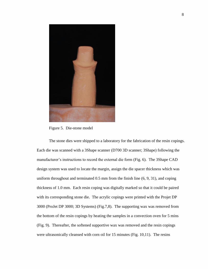
Figure 5. Die-stone model
The stone dies were shipped to a laboratory for the fabrication of the resin copings.
Each die was scanned with a 3Shape scanner (D700 3D scanner; 3Shape) following the
manufacturer’s instructions to record the external die form (Fig. 6). The 3Shape CAD
design system was used to locate the margin, assign the die spacer thickness which was
uniform throughout and terminated 0.5 mm from the finish line (6, 9, 31), and coping
thickness of 1.0 mm. Each resin coping was digitally marked so that it could be paired
with its corresponding stone die. The acrylic copings were printed with the Projet DP
3000 (ProJet DP 3000; 3D Systems) (Fig.7,8). The supporting wax was removed from
the bottom of the resin copings by heating the samples in a convection oven for 5 mins
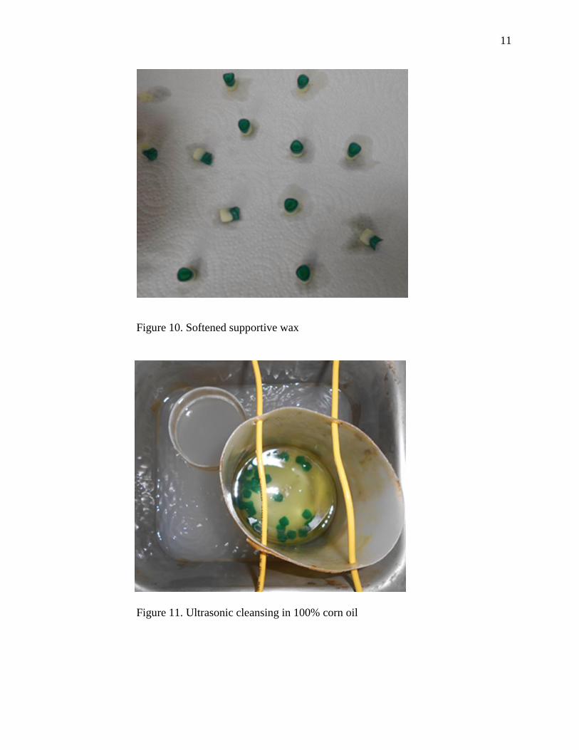
(Fig. 9). Thereafter, the softened supportive wax was removed and the resin copings
were ultrasonically cleansed with corn oil for 15 minutes (Fig. 10,11). The resins

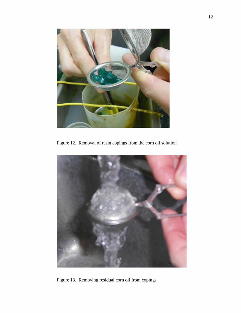
9
copings were removed from the oil and placed into a tea drainer which was dipped into a
mild solution containing dish soap and ran under running warm water faucet until all the
residual oil droplets were removed (Fig. 12-15). All of the laboratory processes were
completed by the same dental technician at a commercial laboratory.
Figure 6: D700 3Shape Scanner
Figure 7. ProJet DP 3000

10
Figure 8. Printed resin patterns with the supportive wax
Figure 9. Convection Oven
11
Figure 10. Softened supportive wax
Figure 11. Ultrasonic cleansing in 100% corn oil
12
Figure 12. Removal of resin copings from the corn oil solution
Figure 13. Removing residual corn oil from copings
13
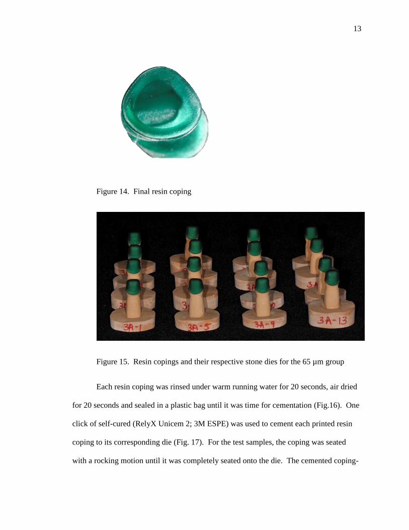
Figure 14. Final resin coping
Figure 15. Resin copings and their respective stone dies for the 65 µm group
Each resin coping was rinsed under warm running water for 20 seconds, air dried
for 20 seconds and sealed in a plastic bag until it was time for cementation (Fig.16). One
click of self-cured (RelyX Unicem 2; 3M ESPE) was used to cement each printed resin
coping to its corresponding die (Fig. 17). For the test samples, the coping was seated
with a rocking motion until it was completely seated onto the die. The cemented coping-

14
die assembly was placed under an apparatus capable of maintaining a static deadweight
load of 5 kg (32) and excess cement was removed with a fine microbrush (Fig. 18). The
Mesial, Distal, Buccal, Lingual surfaces were light cured (Demiplus; Kerr) for 20
seconds each, for a total of 80 seconds. The cemented coping-die assembly was kept
under the weighted-base apparatus for 6 minutes. The samples were stored at room
temperature for at room temperature until sectioning. The cement film thickness was
checked with the ADA Specification No. 8 protocol, section 4.3.4, however, the
recommended seating force was reduced to resemble the load used within this experiment
(5 kg) (Fig 19,20).
Figure 16. Sealed copings prior to cementation procedure
15
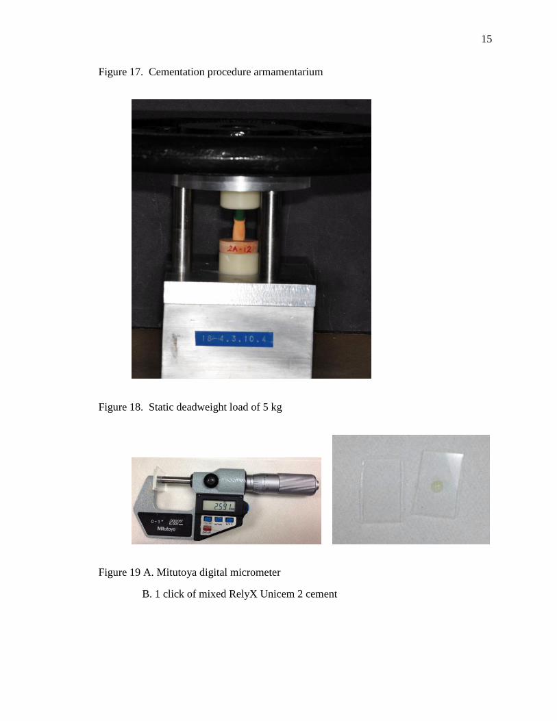
Figure 17. Cementation procedure armamentarium
Figure 18. Static deadweight load of 5 kg
Figure 19 A. Mitutoya digital micrometer
B. 1 click of mixed RelyX Unicem 2 cement
16
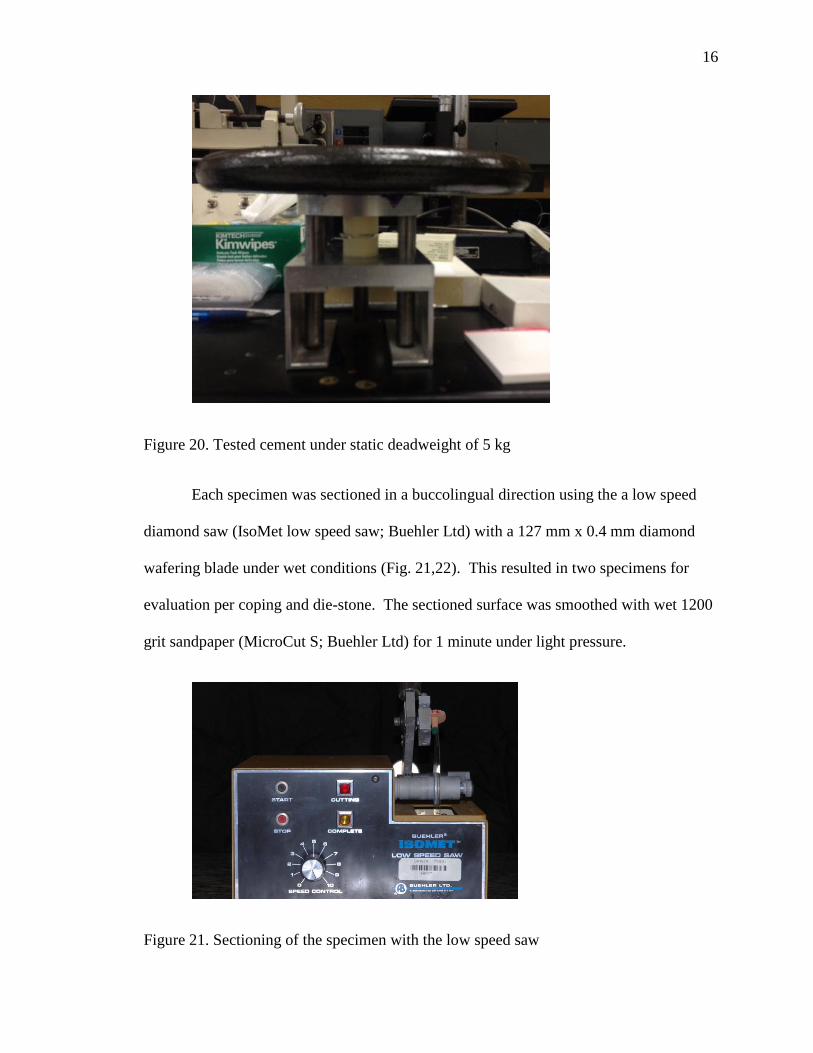
Figure 20. Tested cement under static deadweight of 5 kg
Each specimen was sectioned in a buccolingual direction using the a low speed
diamond saw (IsoMet low speed saw; Buehler Ltd) with a 127 mm x 0.4 mm diamond
wafering blade under wet conditions (Fig. 21,22). This resulted in two specimens for
evaluation per coping and die-stone. The sectioned surface was smoothed with wet 1200
grit sandpaper (MicroCut S; Buehler Ltd) for 1 minute under light pressure.
Figure 21. Sectioning of the specimen with the low speed saw

17
Figure 22. Sectioned specimen into two halves
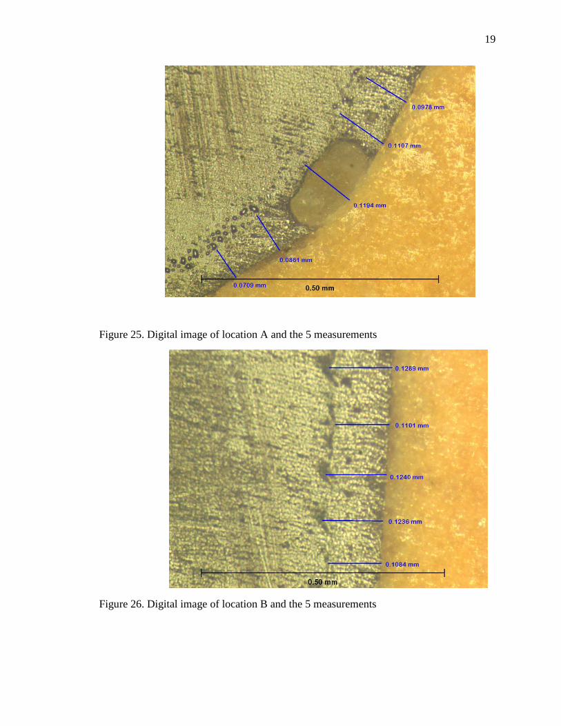
The internal gap between the printed resin coping and stone die, for each
sectioned specimen was measured at 5 defined locations: (A) facial chamfer, (B) facial
mid-axial, (C) incisal, (D) lingual mid-axial, (E) lingual chamfer (Fig. 23).
Figure 23. Locations of the internal gap measurements: A – Facial chamfer, B – Mid
facial, C – Incisal, D – Mid lingual , E – lingual chamfer

18
Five measurements were made to create an average value at each point leading to a total
of 50 measurements (5x2x5) per die. (33) Overall, 4000 measurements (50 x 80) were
obtained for the entire study. The internal gap width image was obtained with an
inverted bright field metallurgical microscope at 100x magnification (Metallograph/
Microscope; Leco/Olympus). The microscope was linked to a digital image acquisition
device and computer software (Spot v4.5 & v5.1; Spot Image) (Fig. 24-29).
Figure 24. Metallograph/ Microscope to linked to a digital image acquisition device and
computer software
19
Figure 25. Digital image of location A and the 5 measurements
Figure 26. Digital image of location B and the 5 measurements
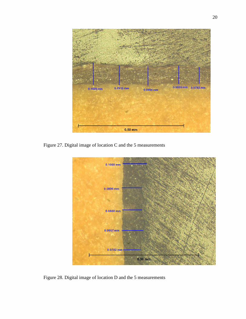
20
Figure 27. Digital image of location C and the 5 measurements
Figure 28. Digital image of location D and the 5 measurements

21
Figure 29. Digital image of location E and the 5 measurements
Mixed models ANOVA with repeated measurements were used to analyze paired
data. The coefficients of variation (CV) were obtained by standard deviation divided by
the mean and multiplied by 100. False discovery rate (FDR) control at level .05 was
employed to account for multiple testing. All analyses were performed in SAS 9.3 (SAS9;
SAS Institute Inc).
22
CHAPTER III
RESULTS
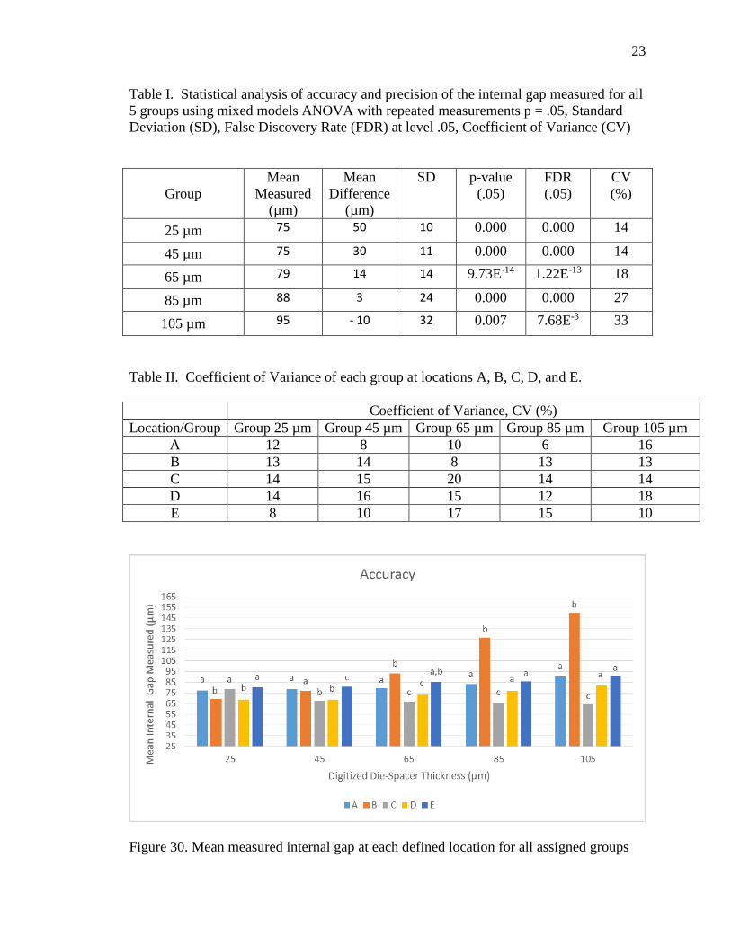
Table I summaries the mean internal gap measurements for the 5 groups along
with their corresponding mean differences. Positive value means the internal gap value
was greater than the prescribed die spacer setting thickness. Negative value means the
internal gap value was smaller than the prescribed die spacer thickness. Mixed models
ANOVA statistical test was used to determine if the differences were statistically
significant. The differences were statistically significant for all 5 groups with p < .05.
FDR values were all statistically significant with FDR < .05 for all groups. CV expressed
in percentages ranged from 14 – 33%.
In Table II summaries the CV values for locations A, B, C, D, and E of all the 5
groups.
Figure 30. A bar graph indicating accuracy of simulated die-spacer thickness of
different locations for all 5 groups. Within each group, same alphabet represents no
statistically significant difference (FDR < .05).
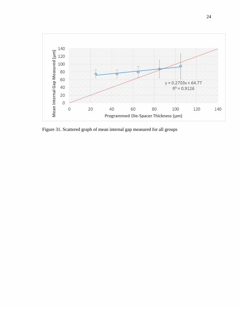
Figure 31. A scattered graph representing the relationship between the
programmed die spacer thickness and the measured internal gaps. With the trendline
equation indicating that even at 0 µm prescribed die spacer thickness the achievable
internal gap was at 65 µm.
23
Table I. Statistical analysis of accuracy and precision of the internal gap measured for all
5 groups using mixed models ANOVA with repeated measurements p = .05, Standard
Deviation (SD), False Discovery Rate (FDR) at level .05, Coefficient of Variance (CV)
Group
Mean
Measured
(µm)
Mean
Difference
(µm)
SD p-value
(.05)
FDR
(.05)
CV
(%)
25 µm 75 50 10 0.000 0.000 14
45 µm 75 30 11 0.000 0.000 14
65 µm 79 14 14 9.73E-14 1.22E-13 18
85 µm 88 3 24 0.000 0.000 27
105 µm 95 - 10 32 0.007 7.68E-3 33
Table II. Coefficient of Variance of each group at locations A, B, C, D, and E.
Coefficient of Variance, CV (%)
Location/Group Group 25 µm Group 45 µm Group 65 µm Group 85 µm Group 105 µm
A 12 8 10 6 16
B 13 14 8 13 13
C 14 15 20 14 14
D 14 16 15 12 18
E 8 10 17 15 10
Figure 30. Mean measured internal gap at each defined location for all assigned groups
24
Figure 31. Scattered graph of mean internal gap measured for all groups

25
CHAPTER IV
DISCUSSION
This study determined that the prescribed die spacer thickness values within the
CAD system differed from the measured internal gaps of the resin copings manufactured
by 3DPT. Therefore, the accuracy null hypothesis for this investigation, where the
programmed die spacer thickness would be the same as the measured internal gap, was
rejected. The machine was unable to produce the same die spacer thickness for all the
samples within an assigned group. The precision null hypothesis, where the internal
gaps produced would be the same at all locations for all the 16 specimens within the same
assigned group, was rejected.
All measurements of the internal gaps between printed resin coping and stone die
were significantly different from prescribed die spacer thickness in all groups. Groups 25
µm, 45 µm, and 65 µm possessed the greatest internal gaps. On the other hand, groups
85 µm and 105 µm had smaller measured values (Table I). However, the magnitude of
inaccuracy of the internal gap observed within this study for groups below the simulated
die-spacer thickness of 85 µm was above the clinical acceptable maximum value
suggested by a previous study of 73 µm for a ceramic crown.(12) The mean cement film
thickness for RelyX Unicem was confirmed to be 15 µm, which is less than the smallest
simulated die spacer thickness. Since the mean internal gap measured for all groups was
greater than 70 µm, the influence of film thickness on incomplete seating for this
experiment is unlikely. From Figure 6, using the trendline equation, at a setting where

26
there is no die spacer thickness (0 µm) in the CAD system, the graph indicates a 65 µm
internal gap would be expected.
The accuracy of die spacer reproduction improved with larger simulated die
spacer thicknesses for locations A, D, and E. However, mean internal gap difference at
location B was consistently 28 - 45 µm greater than the expected value. This
phenomenon might have been caused by the increase fit discrepancy between coping and
die-stone at vertical location on the die. In the absence of a horizontal stop, improved fit
from a seating load would not be anticipated. The opposite was observed for location C,
where occlusal internal gap dimension decreased as the programed die spacer thickness
increased. A greater programed die spacer thickness might have prevented the seating
interference at the occlusal-axial line angle, leading to a better seated coping at the incisal
portion.
The effect of die spacer thickness on crown retention has been reported with
conflicting results.(9, 17, 34) Whereas, the die-spacer thickness has been shown to
improve marginal fit of the coping by providing a physical space for the excess cement to
escape, hence decreasing the hydraulic pressure.(6-10) It has been previously reported
that four layers of die spacer provided marginal gap between 29-45 µm. (4,6) Without die
spacer, the marginal gaps ranged between 333 – 643 µm. (4,23) The internal gap of less
73 µm has been suggested for a ceramic restoration and an internal gap of 120 µm has
been shown to weaken the fracture strength of all ceramic restoration without
significantly improving marginal fit. (26)

27
Precision, expressed as CV in percentage, was used to determine the closeness of
the internal gap measurements to each other. A large CV percentage indicates low
precision. Overall, the precision for all groups in this study was within the range 14 –
33%. Since a precision value less than 10% is considered reasonable (35), the precision
of the CAD/3DPT combination used in this study was low. As programmed die spacer
thickness increased from 25 µm to 105 µm, the precision had greater deviation. That
means the larger die spacer settings were less precise. However, when considering the
measurements per location and for each group, there was no discernable trend for the
precision ranging from 6 - 20%. False discovery rate was less than .05 meaning the
results obtained not by chance.
There are several limitations of this research with respect to measurement location,
material, and technology used. Even though a total of 50 measurements per specimen was
obtained in this study(33), measurements were made in 5 areas. Moreover, it is prudent
to understand that the measurements obtained were specific to this software/hardware
combination (CAD and 3DPT). The results may not be applicable to other
software/hardware combinations. Thus, further studies will be needed to investigate the
accuracy and precision for other comparing technologies. In the future, other advanced
technologies with improved accuracy will be available for both the scanning and printing
systems.
28
CHAPTER V
CONCLUSIONS
Within the limitations of this study, the following conclusions may be drawn:
1. The accuracy of programmed die spacer thickness reproduction of CAD/3DPT
compared with the printed resin coping and stone die showed significant
differences for all the groups.
2. Precision of the measurements obtained for each group was above 10% showing
the machine inability to reproduce the same internal gap width for all locations
within the same group.

29
BIBLIOGRAPHY
1. Cooper TM, Christensen GJ, Laswell HR, Baxter R. Effect of venting on cast gold full
crowns. J Prosthet Dent. 1971;26(6):621-6.
2. Miller GD, Tjan AH. The internal escape channel: a solution to incomplete seating of
full cast crowns. J Am Dent Assoc. 1982;104(3):322-4.
3. Eames WB, O'Neal SJ, Monteiro J, Miller C, Roan JD, Jr., Cohen KS. Techniques to
improve the seating of castings. J Am Dent Assoc. 1978;96(3):432-7.
4. Grajower R, Zuberi Y, Lewinstein I. Improving the fit of crowns with die spacers. J
Prosthet Dent. 1989;61(5):555-63.
5. Aditya P, Madhav VN, Bhide SV, Aditya A. Marginal discrepancy as affected by
selective placement of die-spacer: an in vitro study. J Indian Prosthodont Soc.
2012;12(3):143-8.
6. Carter SM, Wilson PR. The effects of die-spacing on post-cementation crown
elevation and retention. Aust Dent J. 1997;42(3):192-8.
7. Wang CJ, Millstein PL, Nathanson D. Effects of cement, cement space, marginal
design, seating aid materials, and seating force on crown cementation. J Prosthet
Dent. 1992;67(6):786-90.
8. Cho SH, Chang WG, Lim BS, Lee YK. Effect of die spacer thickness on shear bond
strength of porcelain laminate veneers. J Prosthet Dent. 2006;95(3):201-8.
9. Carter SM, Wilson PR. The effect of die-spacing on crown retention. Int J Prosthodont.
1996;9(1):21-9.
10. Psillakis JJ, McAlarney ME, Wright RF, Urquiola J, MacDonald DE. Effect of
evaporation and mixing technique on die spacer thickness: a preliminary study. J
Prosthet Dent. 2001;85(1):82-7.
11. Holmes JR, Bayne SC, Holland GA, Sulik WD. Considerations in measurement of
marginal fit. J Prosthet Dent. 1989;62(4):405-8.
12. Tuntiprawon M, Wilson PR. The effect of cement thickness on the fracture strength
of all-ceramic crowns. Aust Dent J. 1995;40(1):17-21.
13. Rekow D, Thompson VP. Near-surface damage--a persistent problem in crowns
obtained by computer-aided design and manufacturing. Proc Inst Mech Eng H.
2005;219(4):233-43.
14. Nakamura T, Dei N, Kojima T, Wakabayashi K. Marginal and internal fit of Cerec 3
30
CAD/CAM all-ceramic crowns. Int J Prosthodont. 2003;16(3):244-8.
15. Rekow ED. A review of the developments in dental CAD/CAM systems. Curr Opin
Dent. 1992;2:25-33.
16. Alghazzawi TF, Liu PR, Essig ME. The effect of different fabrication steps on the
marginal adaptation of two types of glass-infiltrated ceramic crown copings
fabricated by CAD/CAM technology. J Prosthodont. 2012;21(3):167-72.
17. Passon C, Lambert RH, Lambert RL, Newman S. The effect of multiple layers of
die-spacer on crown retention. Oper Dent. 1992;17(2):42-9.
18. Gegauff AG, Rosenstiel SF. Reassessment of die-spacer with dynamic loading during
cementation. J Prosthet Dent. 1989;61(6):655-8.
19. Campagni WV, Wright W, Martinoff JT. Effect of die spacer on the seating of
complete cast gold crowns with grooves. J Prosthet Dent. 1986;55(3):324-8.
20. Campagni WV, Preston JD, Reisbick MH. Measurement of paint-on die spacers used
for casting relief. J Prosthet Dent. 1982;47(6):606-11.
21. Campbell SD. Comparison of conventional paint-on die spacers and those used with
the all-ceramic restorations. J Prosthet Dent. 1990;63(2):151-5.
22. Oliva RA, Lowe JA. Effect of die spacer on the seating of cast restorations on
composite core preparations. J Prosthet Dent. 1987;58(1):29-35.
23. Van Nortwick WT, Gettleman L. Effect of internal relief, vibration, and venting on
the vertical seating of cemented crowns. J Prosthet Dent. 1981;45(4):395-9.
24. Hager TS, Gardner FM, Edge MJ. The effect of selective die spacer placement
techniques on the seatability of castings. J Prosthodont. 1993;2(1):56-60.
25. KG C. Rapid Prototyping Technology. 1st Ed ed. New York:Basel2005.
26. Silva NR, Witek L, Coelho PG, Thompson VP, Rekow ED, Smay J. Additive
CAD/CAM process for dental prostheses. J Prosthodont. 2011;20(2):93-6.
27. Moldovan O, Luthardt RG, Corcodel N, Rudolph H. Three-dimensional fit of
CAD/CAM-made zirconia copings. Dent Mater. 2011;27(12):1273-8.
28. Tan PL, Gratton DG, Diaz-Arnold AM, Holmes DC. An in vitro comparison of
vertical marginal gaps of CAD/CAM titanium and conventional cast restorations.
J Prosthodont. 2008;17(5):378-83.
29. Beuer F, Aggstaller H, Edelhoff D, Gernet W, Sorensen J. Marginal and internal fits
31
of fixed dental prostheses zirconia retainers. Dent Mater. 2009;25(1):94-102.
30. Bhaskaran E, Azhagarasan NS, Miglani S, Ilango T, Krishna GP, Gajapathi B.
Comparative Evaluation of Marginal and Internal Gap of Co-Cr Copings
Fabricated from Conventional Wax Pattern, 3D Printed Resin Pattern and DMLS
Tech: An In Vitro Study. J Indian Prosthodont Soc. 2013;13(3):189-95.
31. Beuer F, Aggstaller H, Richter J, Edelhoff D, Gernet W. Influence of preparation
angle on marginal and internal fit of CAD/CAM-fabricated zirconia crown
copings. Quintessence Int. 2009;40(3):243-50.
32. Olivera AB, Saito T. The effect of die spacer on retention and fitting of complete cast
crowns. J Prosthodont. 2006;15(4):243-9.
33. Wood KC, Berzins DW, Luo Q, Thompson GA, Toth JM, Nagy WW. Resistance to
fracture of two all-ceramic crown materials following endodontic access. J
Prosthet Dent. 2006;95(1):33-41.
34. Nawafleh NA, Mack F, Evans J, Mackay J, Hatamleh MM. Accuracy and reliability
of methods to measure marginal adaptation of crowns and FDPs: a literature
review. J Prosthodont. 2013;22(5):419-28.
35. Vermilyea SG, Kuffler MJ, Huget EF. The effects of die relief agent on the retention
of full coverage castings. J Prosthet Dent. 1983;50(2):207-10.
36. ÖHman C, Baleani M, Viceconti M. Repeatability of experimental procedures to
determine mechanical behaviour of ligaments. Acta of Bioengineering &
Biomechanics. 2009;11(1):19-23.