achieving flexibility and performance for packet...
TRANSCRIPT

Achieving Flexibility and Performance for Packet Forwardingand Data Center Management
by
Daekyeong Moon
A dissertation submitted in partial satisfaction of the
requirements for the degree of
Doctor of Philosophy
in
Computer Science
in the
Graduate Division
of the
University of California, Berkeley
Committee in charge:
Professor Scott J. Shenker, ChairProfessor Ion Stoica
Professor Tapan Parikh
Spring 2010
Achieving Flexibility and Performance for Packet Forwardingand Data Center Management
Copyright c© 2010
by
Daekyeong Moon

1
Abstract
Achieving Flexibility and Performance for Packet Forwardingand Data Center Management
by
Daekyeong MoonDoctor of Philosophy in Computer Science
University of California, Berkeley
Professor Scott J. Shenker, Chair
Although today’s networking equipment has achieved high performance and lowcost by embedding forwarding logic in hardware, this has come at the price of severelyreduced flexibility. In this dissertation, we address the problem of achieving both flexi-bility and performance in two networking domains: packet forwarding and data centernetworking. In packet forwarding, we present Software Defined Forwarding, a hybriddesign that attempts to combine the high speed and low cost of hardware with thesuperior flexibility of software. Within the data center context, we propose Ripcord,a platform for data center routing and management. Through simulation, prototypeimplementation and testbed experiments, we demonstrate that these solutions achieveboth flexibility and high performance in their respective contexts.
Professor Scott J. ShenkerDissertation Committee Chair

i
To my family and Hayan.

ii
Contents
List of Figures v
List of Tables vi
1 Introduction 11.1 Problem statement . . . . . . . . . . . . . . . . . . . . . . . . . . . . 21.2 Contribution . . . . . . . . . . . . . . . . . . . . . . . . . . . . . . . . 2
1.2.1 Software Defined Forwarding . . . . . . . . . . . . . . . . . . . 21.2.2 Ripcord: Data Center Routing/Management Platform . . . . 3
1.3 Dissertation Organization . . . . . . . . . . . . . . . . . . . . . . . . 4
2 Background 52.1 The Status Quo in Packet Forwarding . . . . . . . . . . . . . . . . . . 52.2 Data Center Networking Aspects . . . . . . . . . . . . . . . . . . . . 72.3 Summary . . . . . . . . . . . . . . . . . . . . . . . . . . . . . . . . . 8
3 Software Defined Forwarding 93.1 Goals, Limitations, and Applicability . . . . . . . . . . . . . . . . . . 9
3.1.1 Goals . . . . . . . . . . . . . . . . . . . . . . . . . . . . . . . . 93.1.2 Limitations . . . . . . . . . . . . . . . . . . . . . . . . . . . . 103.1.3 Applicability . . . . . . . . . . . . . . . . . . . . . . . . . . . 10
3.2 Overview . . . . . . . . . . . . . . . . . . . . . . . . . . . . . . . . . . 113.2.1 System Functionality and Components . . . . . . . . . . . . . 113.2.2 Forwarding Steps . . . . . . . . . . . . . . . . . . . . . . . . . 133.2.3 Sound Familiar? . . . . . . . . . . . . . . . . . . . . . . . . . . 14
3.3 System Design . . . . . . . . . . . . . . . . . . . . . . . . . . . . . . . 153.3.1 API . . . . . . . . . . . . . . . . . . . . . . . . . . . . . . . . 153.3.2 System Software . . . . . . . . . . . . . . . . . . . . . . . . . 193.3.3 Hardware . . . . . . . . . . . . . . . . . . . . . . . . . . . . . 20
3.4 Implementation . . . . . . . . . . . . . . . . . . . . . . . . . . . . . . 223.4.1 NetFPGA prototype . . . . . . . . . . . . . . . . . . . . . . . 223.4.2 Microbenchmarks. . . . . . . . . . . . . . . . . . . . . . . . . 24

iii
3.5 Summary . . . . . . . . . . . . . . . . . . . . . . . . . . . . . . . . . 24
4 SDF Use Cases 264.1 Accelerating Existing Software Routers . . . . . . . . . . . . . . . . . 264.2 Virtualization . . . . . . . . . . . . . . . . . . . . . . . . . . . . . . . 274.3 Implementing Forwarding Algorithms . . . . . . . . . . . . . . . . . . 29
4.3.1 L2 Learning Switch . . . . . . . . . . . . . . . . . . . . . . . . 294.3.2 IPv4 and IPv6 Forwarding . . . . . . . . . . . . . . . . . . . . 304.3.3 Floodless in SEATTLE . . . . . . . . . . . . . . . . . . . . . . 324.3.4 i3 and Chord . . . . . . . . . . . . . . . . . . . . . . . . . . . 33
4.4 Summary . . . . . . . . . . . . . . . . . . . . . . . . . . . . . . . . . 33
5 SDF Performance Study 345.1 Assumption . . . . . . . . . . . . . . . . . . . . . . . . . . . . . . . . 345.2 L2 learning . . . . . . . . . . . . . . . . . . . . . . . . . . . . . . . . 365.3 IPv4 forwarding . . . . . . . . . . . . . . . . . . . . . . . . . . . . . . 365.4 Performance under stressful conditions . . . . . . . . . . . . . . . . . 385.5 Summary . . . . . . . . . . . . . . . . . . . . . . . . . . . . . . . . . 40
6 Ripcord: Platform for Data Center Routing and Management 416.1 Overview . . . . . . . . . . . . . . . . . . . . . . . . . . . . . . . . . . 41
6.1.1 Design Requirements . . . . . . . . . . . . . . . . . . . . . . . 426.1.2 Key Criteria for Data Center Networking . . . . . . . . . . . . 426.1.3 Ripcord’s Design Principles . . . . . . . . . . . . . . . . . . . 426.1.4 Prototype . . . . . . . . . . . . . . . . . . . . . . . . . . . . . 43
6.2 Design . . . . . . . . . . . . . . . . . . . . . . . . . . . . . . . . . . . 446.2.1 Example Walkthrough . . . . . . . . . . . . . . . . . . . . . . 446.2.2 Components . . . . . . . . . . . . . . . . . . . . . . . . . . . . 45
6.3 Implementation . . . . . . . . . . . . . . . . . . . . . . . . . . . . . . 486.3.1 Configuration & Policy Database . . . . . . . . . . . . . . . . 486.3.2 Topology Engine . . . . . . . . . . . . . . . . . . . . . . . . . 486.3.3 Authenticator-Demultiplexer . . . . . . . . . . . . . . . . . . . 486.3.4 App Engine and Management Apps . . . . . . . . . . . . . . . 496.3.5 Routing Engine and Per-tenant Routing Pipeline . . . . . . . 506.3.6 Monitoring Implementation . . . . . . . . . . . . . . . . . . . 516.3.7 Flow Installer . . . . . . . . . . . . . . . . . . . . . . . . . . . 516.3.8 Virtual-to-Physical Mapping . . . . . . . . . . . . . . . . . . . 52
6.4 Case studies . . . . . . . . . . . . . . . . . . . . . . . . . . . . . . . . 536.4.1 Proactive L2 routing . . . . . . . . . . . . . . . . . . . . . . . 536.4.2 VL2 . . . . . . . . . . . . . . . . . . . . . . . . . . . . . . . . 536.4.3 PortLand . . . . . . . . . . . . . . . . . . . . . . . . . . . . . 546.4.4 Additional Capabilities . . . . . . . . . . . . . . . . . . . . . . 55

iv
6.5 Evaluation . . . . . . . . . . . . . . . . . . . . . . . . . . . . . . . . . 566.5.1 Software testbed . . . . . . . . . . . . . . . . . . . . . . . . . 566.5.2 Hardware testbed . . . . . . . . . . . . . . . . . . . . . . . . . 566.5.3 Experiments on Software Testbed . . . . . . . . . . . . . . . . 576.5.4 Experiment on Hardware Testbed . . . . . . . . . . . . . . . . 596.5.5 Flow Table Size . . . . . . . . . . . . . . . . . . . . . . . . . . 606.5.6 Running Simultaneous Ripcord Applications . . . . . . . . . . 60
6.6 Scalability . . . . . . . . . . . . . . . . . . . . . . . . . . . . . . . . . 616.7 Related Work . . . . . . . . . . . . . . . . . . . . . . . . . . . . . . . 64
7 Conclusion 667.1 Contribution Summary . . . . . . . . . . . . . . . . . . . . . . . . . . 667.2 Future Directions . . . . . . . . . . . . . . . . . . . . . . . . . . . . . 67
Bibliography 68

v
List of Figures
3.1 High-level view of software defined forwarding. . . . . . . . . . . . . . 113.2 A distributed forwarding architecture. . . . . . . . . . . . . . . . . . . 203.3 Packet processing pipeline of the NetFPGA prototype. User data path
refers to custom logic on the FPGA. . . . . . . . . . . . . . . . . . . 23
4.1 Supporting an existing software router by a simple forwarding appli-cation implementing the forwarding engine abstraction of the softwarerouter. . . . . . . . . . . . . . . . . . . . . . . . . . . . . . . . . . . . 27
4.2 Supporting network virtualization in SDF. . . . . . . . . . . . . . . . 29
5.1 Simulations of cache miss rates for L2 learning with the enterprise trace. 365.2 Cache miss rates for ISP-US trace (top) and ISP-EU trace (bottom). 375.3 Cache miss rates with forwarding on the /16 and /24 granularities for
the OC-48 (top) and the OC192-C trace (bottom). . . . . . . . . . . 385.4 Cache miss rates with (and without) random DoS traffic comprising
50% of the traffic for the ISP-EU trace (top). Cache miss rates withrandom DoS traffic for the ISP-US trace (bottom). . . . . . . . . . . 39
6.1 Ripcord architecture and event flow diagram . . . . . . . . . . . . . . 466.2 App configuration example (PortLand). Each app is assigned a unique
app ID. It also specifies a routing pipeline in the form of a list of routingmodules. . . . . . . . . . . . . . . . . . . . . . . . . . . . . . . . . . . 49
6.3 Global routing policy example. . . . . . . . . . . . . . . . . . . . . . . 506.4 Fat Tree topology and CDF of 1-to-many host ping delays on the soft-
ware test using the topology. Leaf nodes in the topology represent endhosts. Proactive means proactively installed APSP. . . . . . . . . . . 57
6.5 Clos topology and CDF of 1-to-many host ping delays on the softwaretestbed using the topology. Leaf nodes in the topology represent endhosts. . . . . . . . . . . . . . . . . . . . . . . . . . . . . . . . . . . . 58
6.6 CDF of 1 to many host ping delays on the hardware testbed. . . . . . 596.7 Simultaneous running of multiple Ripcord Management Applications 62

vi
List of Tables
3.1 Forwarding API. The core calls are for receiving/sending packets, “InPkt”and “OutPkt” are for packet operations, while “Control” is for controlplane parts of the application. . . . . . . . . . . . . . . . . . . . . . . 16
3.2 Cache insertion/deletion performance of the NetFPGA prototype. . . 243.3 Throughput of the NetFPGA prototype. . . . . . . . . . . . . . . . . 24
5.1 Traces used in the cache hit-rate evaluations. . . . . . . . . . . . . . . 35
6.1 Network events that Ripcord expects from switch. . . . . . . . . . . . 436.2 Switch commands expected by Ripcord. . . . . . . . . . . . . . . . . 446.3 Ripcord’s routing pipeline stages. Earlier stages in the table cannot
appear later in routing pipeline. Each routing module should be in oneof these stages. . . . . . . . . . . . . . . . . . . . . . . . . . . . . . . 47
6.4 Information included in a monitoring snapshot. . . . . . . . . . . . . 516.5 API exposed by the monitoring module for active statistics collection. 526.6 Lines of code of sample routing implementation . . . . . . . . . . . . 536.7 OpenFlow entries realizing compact VL2 routing. . . . . . . . . . . . 546.8 The number of flow entries installed at each switch by VL2 implemen-
tation with no flow idle timeout. . . . . . . . . . . . . . . . . . . . . . 606.9 The number of flow entries installed at each switch by VL2 implemen-
tation with flow idle timeout of 3 seconds. . . . . . . . . . . . . . . . 61

vii
Acknowledgments
It is always difficult to write acknowledgements, since I am afraid of accidentallyexcluding people who really deserve appreciation. My life as a graduate student at UCBerkeley would never have been possible without help from my outstanding advisors,talented colleagues, and supportive friends and family. Therefore, my graduationis merely an opportunity to acknowledge their valuable help and great kindness tome. In a sense, this space is too small to enumerate all their names. Despite adissertation bearing only a single name, I believe that it must be they who mostdeserve the recognition.
My appreciation for my research advisor, Professor Scott J. Shenker, has no bounds.He was the best source of research ideas and the most dependable person to ask forfeedback throughout my Ph.D. course. The ideas in this dissertation could not havebeen fully explored without his great insight and guidance. Not only has he guidedme in research, he has also treated me as an individual and encouraged me when Iwas at my most difficult moments. I also believe that I have learned a lot from hishumility and respect for others.
I am very grateful to my dissertation committee members Professor Ion Stoica andProfessor Tapan Parikh for their valuable feedback during my qualifying exam andreview of this dissertation. I also greatly enjoyed working with Ion as his teachingassistant. I also have to thank Professor Randy H. Katz for serving on my qualifyingexam committee and providing valuable comments.
It is my great fortune to have had the chance to work with Martin Casado andTeemu Koponen. It was Martin who has occasionally provided me with high-levelresearch direction and inspired me to pursue this dissertation. I marveled at Teemu’sbroad and in-depth understanding of computer networking and technologies. I learneda lot from discussion with him and from his source code.
I also deeply appreciate the help of my colleague students in the Shenker group.Projects with them has taught me about teamwork and collaboration. Especially, Ithank Andrey Ermolinskiy and Byung-gon Chun for the Minuet project and JundaLiu, Igor Ganichev and Kyriakos Zarifis for the SDF project and NOX-related projects.I also have to thank Brandon Heller, David Erickson and Professor Nick McKeownat Stanford for their amazing collaboration during the Ripcord project.
I am grateful to my parents who have remained consistently supportive throughoutmy studies. Finally, I thank Hayan Yoon for encouraging me throughout the lastthree years.

1
Chapter 1
Introduction
It is a tired cliche to remark on the success that the Internet has over the lasttwo decades, but that success is undeniable and unprecedented. Much of this successis due to the structure of the Internet architecture, with its “narrow waist” of IPenabling radical innovations both above and below this internetworking layer. Thenetworking industry has in turn built equipment (i.e. routers and switches) withrapidly improving performance/cost ratios by embedding IP and other features inthe forwarding hardware.
Although the use of specialized hardware has succeeded in offering high perfor-mance, it often requires a major infrastructure upgrade to implement changes innetwork architecture. This hardware rigidity has created an innovation deadlock;new ideas require infrastructure support to evaluate and verify, while operators won’tdeploy new ideas until they are verified through experiments and implemented inhardware. By relying on specialized hardware for its implementation of the forward-ing path, the networking industry has given up the ability to innovate on the for-warding path in return for performance. Therefore, the today’s Internet has difficultyaccommodating new networking requirements (e.g., security, management, etc.) andoperating environments (e.g. data centers, developing regions, etc.).
Researchers have tried to overcome this innovation impasse. For example, researchon overlay networks blossomed in early 2000s, and these networks have great flexi-bility, but their performance is lacking. Many thought network processors would theanswer in this regard, but they have not proven capable of providing the necessaryperformance for a reasonable price.
The lack of innovation is not only felt in the standard networking settings, but alsoin more recent operating environments such as data center networking and network-ing in developing regions. Designs for these new operating environments often adopt

2
home-brewed solutions to tackle domain-specific problems (e.g., full bisectional band-width in the data center, delay-tolerance in developing regions, etc.). Hence, solutionsare barely interchangeable, even in the same domain. This means new operating en-vironments are at the risk of being locked into non-standard architectures/protocolsby their hardware rigidity.
For instance, the many proposals (e.g., [12, 14, 17, 20, 32]) for data center network-ing make specific assumptions about the low-level topology or are otherwise limitedin their applicability. A more flexible approach, that can apply to a broader set ofuse cases, would be far more desirable. In this way, achieving flexibility in data cen-ter networking shares many high-level ideas with accomplishing flexibility in packetforwarding.
1.1 Problem statement
This dissertation focuses on how to achieve both high flexibility and low cost intwo networking domains: classical packet forwarding and data center networking.
1.2 Contribution
Our contribution is twofold:
1. We present a new hardware design approach called “Software Defined Forward-ing” to the classical high-speed packet-forwarding problem. We have imple-mented and evaluated the proposed approach in both software and hardware.
2. We propose a general routing and management platform called “Ripcord” fordata center networking. We have implemented a prototype and evaluated it byrunning recent data center routing algorithms.
1.2.1 Software Defined Forwarding
In packet forwarding, we propose a hybrid design that attempts to combine thehigh speed and low cost of hardware with the superior flexibility of software. We mo-tivate our approach by noting that current hardware-accelerated packet-forwardingimplements the forwarding logic in hardware. In contrast, in our approach all for-warding decisions are first made in software and thereafter imitated by hardware.The hardware uses a classification engine to match software-made decisions with theincoming packets to which they apply (e.g., all packets destined for the same prefix).Thus, the hardware does not need to understand the logic of packet forwarding, itmerely stores the results of forwarding decisions (previously made by software) and

3
applies them to packets with the appropriate headers. In short, hardware caches thedecisions made by software and executes them at high-speed.
Similarly, the forwarding software is not tied to a particular hardware implementa-tion. Instead, forwarding algorithms are programmed against a high-level API, whichincreases portability and reduces the complexity of implementation. This forwardingsoftware is not speed-critical, so it can be written in a high-level language (in ourimplementations we have used Python as well as C++).
For lack of a better term, we call this decision-caching approach Software-DefinedForwarding (SDF), since all forwarding decisions are made in software. To demon-strate the viability of SDF, we built a complete system in hardware and software. Ontop of it, we have implemented a number of conventional forwarding algorithms (L2Ethernet forwarding and L3 longest-prefix-matching), ported an existing code base(XORP), as well as implemented several recently proposed algorithms (SEATTLE,i3, Chord). We have also implemented a virtualization layer in software that allowsmultiple forwarding algorithms to operate in parallel on the same hardware; doing sodid not require any change to the hardware forwarding model.
1.2.2 Ripcord: Data Center Routing/Management Platform
In data center networking, we present (based on joint work with the Stanfordteam) a new routing and management platform, called Ripcord. Ripcord providesa uniform control interface to a physical network so as to abstract high-level datacenter networking solutions from underlying network. This control interface is logi-cally centralized so that schemes using the interface do not suffer from the need toimplement complex distributed algorithms.
In addition, Ripcord supports multiple tenants. Each tenant on Ripcord is a logicalentity (e.g., data center customers, services, jobs, etc) requiring a separate treatmentin routing/management. These tenants are isolated from each other and can cus-tomize their routing and management with Ripcord modules. A researcher may usethis capability to evaluate two schemes side by side (or even simultaneously); an ex-perimental data center can host multiple researchers at the same time; a multi-tenanthosting service may provide different customers with different logical networks; anda multi-service data center may use schemes optimized for different services. For ex-ample, one scheme could be for MapReduce, alongside another for video streaming.We later illustrate this by running VL2 [12] and Portland [32] at the same time.
Ripcord is also modular in order to facilitate code re-use and rapid prototyping.Ripcord consists of a collection of key components with a well-defined interface and

4
additional routing/management modules. Thus, data center operators may developa new module for their data centers or share modules to add features into their datacenters. Tenants can easily benefit from the new features in additional modules.
We guided the development of Ripcord from our observation that recent data cen-ter networking proposals (e.g., VL2 [12], Monsoon [14], BCube [17], PLayer [20],and PortLand [32]) present solutions based on specific requirements, some of whichoverlap across solutions, but may be prioritized differently in each solution. As a con-sequence, specific architectural choices often make it difficult to accommodate newrequirements, changes to data center environments or modifications to the solutionthat attempt to tailor/tweak it for another data center environment. Ripcord is not indirect competition with any of these networking proposals; rather, it provides a plat-form that allows network administrators to experiment with one or more data centernetworking proposals (side by side if necessary), make modifications, and evaluatethe proposal in their own data center environments.
1.3 Dissertation Organization
In the following chapter, we review the limitation of current design options to buildpacket-forwarding devices and discuss the incompatibility of data center networkingsolutions. Chapter 3 presents the SDF approach and describes our prototype imple-mentation, followed by the use case study and performance study of SDF in Chapters 4and Chapter 5. In Chapter 6, we describe the Ripcord framework and demonstratehow Ripcord can achieve flexibility in data center networking by implementing recentdata center algorithms.

5
Chapter 2
Background
This chapter reviews the shortcomings of current design approaches to buildingpacket forwarding devices and discuss the inability of data centers to implementchanges.
2.1 The Status Quo in Packet Forwarding
As network speeds increase, and network requirements diversify, networking hard-ware vendors are being pressed on two distinct fronts. To remain competitive, theymust continually improve their cost/performance ratio at a pace faster than Moore’sLaw. Over the past fifteen years, enterprise network speeds have increased by threeorders of magnitude, from 10Mbps to 10Gbps, requiring that the cost of a unit ofbandwidth (a gigabit port, or Gport) drop precipitously. At the same time, networksare expected to address myriad application, management and security requirementsthat were unheard of fifteen years ago, creating pressure to develop network forward-ing devices that can flexibly accommodate these new demands as they arise. Thistrend is reflected in the many “open” platform initiatives launched by system ven-dors [29, 9, 21].
Despite significant research and engineering efforts, the industry has failed to simul-taneously achieve low cost/performance and high flexibility.1 There are three basicapproaches to building network forwarding devices currently pursued in the field and,as we relate below, they offer quite different tradeoffs between these two goals.
1When we refer to flexibility, we mean the flexibility in forwarding algorithms, not general pro-grammability for sophisticated packet processing. As we clarify later, we are not addressing network“appliances” that provide deep packet inspection. Our concern here is only for packet forwardingdecisions: to which output port does this packet go, and how should its header be rewritten?

6
In the commercial world, where cost concerns dominate, the most prevalent ap-proach to building network forwarding devices (this includes both switches and routers,but hereafter we will use the term “switch” as shorthand) involves embedding thebasic forwarding logic in ASICs. There are commodity forwarding chips (from, forexample, Broadcom, Marvell, and Fulcrum) that cost as little as $20/10Gport, a price-point that would have been unthinkable only a few years ago. Multi-layer switchesusing these commodity chips support 240Gbps (24x10Gbps) of capacity for under$100/10Gport, and 640Gbps (64x10Gbps) chipsets will be generally available thisyear which should lower the cost even further. However, one cannot modify the hard-ware forwarding algorithm without respinning the chip. This forces packet forwardingto evolve on hardware design timescales, which are glacially slow compared to the rateat which network requirements are changing.
In the research community, where flexibility is paramount, there has been renewedinterest in purely software-based switches (i.e., switches running commodity operat-ing systems on general-purpose CPUs); see, for example, [10]. These designs havethe requisite flexibility, since new forwarding algorithms merely require additionalprogramming, but their port-density and cost/performance remains poor. For exam-ple, software routers on general CPUs have been shown to support 10Gbps of trivialforwarding for minimum size packets [10], achieving roughly $1000/10Gport, an or-der of magnitude more than the ASIC-based switches. While prevalent in low-speedwireless devices, pure software switches have made almost no penetration into thehigh-speed, high-fanout wireline market.
The industry has tried to bridge the divide between these two extremes with “net-work processors”, whose goal was to provide programmable functionality at near-commodity hardware costs. Unfortunately, network processors have not realized thisgoal, as designers have yet to find a sweet-spot in the tradeoff between hardwaresimplicity and flexible functionality. The cost/performance ratios have lagged wellbehind commodity networking chips and the interface provided to software has provenhard to use, requiring protocol implementors to painstakingly contort their code tothe idiosyncrasies of the particular underlying hardware to achieve reasonable per-formance.2 These two problems (among others) have prevented network processorsfrom dislodging the more narrowly targeted commodity packet-forwarding hardwarethat dominates the market today. One area in which network processors are widelyused is in network appliances, which go beyond mere forwarding to do deep packetinspection; but even here, after initial success, network processors are starting tolose market share as the forwarding performance of general-purpose CPUs has signif-icantly improved. Today many market-leading middleboxes (such as load balancers)are implemented on standard x86 platforms.
2However, CAFE [27] is a promising approach for datacenter forwarding.

7
2.2 Data Center Networking Aspects
The meteoric growth of data centers over the past decade has redefined how theyare designed and built. Today, a large data center may contain over one hundred thou-sand servers and tens of thousands of individual networking components (switches,routers or both). Data centers often host many applications with dynamic capacityrequirements, and differing service requirements. For example, it is not uncommon forthe same data center to host applications requiring terabytes of internal bandwidth,and others requiring low-latency streaming to the Internet.
Their sheer scale, coupled with application dynamics and diversity, makes datacenters unlike any systems that have come before. And to construct and managethem, network designers have had to rethink traditional methodologies. A prevailingdesign principle is to use “scale-out” system design. Scale-out systems are generallycharacterized by the use of redundant commodity components. Managed workloadsare constructed so the system can gracefully tolerate component failures. Capacityis increased by adding hardware without requiring new configuration state or systemsoftware.
While scale-out design is well understood for building compute services from com-modity end-hosts, it is a relatively new way to build out network capacity whileretaining a rich service model to applications. Researches [12, 32] have explainedclearly how traditional data center networks stood in the way of supporting highlydynamic applications, scale-out bandwidth, and the commodity cost model such sys-tems are suited for.
Due to these limitations, the research community, and the largest data center oper-ators – those with the deepest pockets – innovate fast, moving towards new schemesthat allow them to construct systems with the requisite properties for their operations.While many schemes remain proprietary and unpublished, some notable data centernetwork designs have been described. VL2 [12] uses Valiant load balancing [24, 53]and IP-in-IP encapsulation to spread traffic over a network of unmodified switches.On the other hand, PortLand [32] modifies the switches to route based on a pseudo-MAC header, and aims to eliminate switch configuration. Other researchers haveproposed Monsoon [14] and FatTree [1]; Trill [51] and DCE [8] have been proposedas standards.
Each proposal holds a unique point in the design space, and subtle differences canhave large ramifications on cost and performance, leading research questions that howwe can evaluate which scheme is best for a given data center (or service) and how
8
we can build on the work of others, modifying an existing scheme to suit particularneeds.
2.3 Summary
In this chapter, we have described the current practices to design packet forward-ing hardware and data center networking. All the traditional approaches to buildingpacket forwarding equipments have limitations to simultaneously achieve flexibilityand low cost/performance. In data center networking, due to use of home-brewedsolutions data centers suffer inability to compare solutions and to adopt foreign solu-tions.
In the next chapter, we present software defined forwarding (SDF) and explain howSDF enables packet forwarding equipments both high flexibility and low cost/perfor-mance, leaving our solution to data center networking for Chapter 6.

9
Chapter 3
Software Defined Forwarding
As described in Chapter 2, current design approaches to building switches do notsimultaneously guarantee flexibility in forwarding algorithms and high performance-to-cost rate. In this chapter, we explore a new design point, called “Software DefinedForwarding (SDF)”, in the design spectrum. SDF is a hybrid approach that attemptsto combine the high speed and low cost of hardware with the superior flexibility ofsoftware. In SDF, all the forwarding decisions are first made in software and thenmimicked by hardware by caching them in a classification engine.
In the rest of the chapter, we first clarify the goals and limitations of SDF, thenpresent its design details, and finally, describe our prototypes in software and hard-ware. In the following Chapter 4 and 5, we illustrate how a wide range of forwardingbehaviors can be implemented on top of SDF and present its performance studyresults, respectively.
3.1 Goals, Limitations, and Applicability
Before delving into design details and performance results, we first articulateSDF’s goals, limitations and applicability.
3.1.1 Goals
The immediate goal of the SDF approach is to build switches with more forward-ing flexibility by having all forwarding decisions determined completely in softwareand then imitated by hardware. This will allow networks to deploy new forwardingalgorithms (such as to support a new protocol) without changing their networkinghardware. In fact, as we discuss later, this will enable networks to run several differentforwarding algorithms in parallel on the same switch.

10
The longer term goal is to create an environment where both hardware and softwaredesigners can independently focus on their respective tasks. Hardware designers canfocus on building “decision caches” with higher speeds, greater fanouts, larger mem-ory, lower power and lower cost. Similarly, software designers can address emergingnetworking requirements by implementing new forwarding algorithms against a sim-ple and fixed hardware interface. This strict separation of concerns should engenderrapid progress in both hardware and software.
3.1.2 Limitations
We reiterate that the SDF approach only supports standard header-based forward-ing and does not apply to more complex networking behaviors such as deep-packetinspection or arbitrary packet modification (like encryption). More specifically, theforwarding decisions can depend only on the header of the incoming packet (wherethe definition of “header” is the first n bits of the packet, where n is flexible) and onthe internal state of the forwarding logic implementation. The output packets candiffer from the incoming packet in the content (and the length) of the header, but thisnew header content can not depend on any forwarding logic state modified per packet(that is, for all packets matching a particular entry, the headers must be modified inthe same way). Thus, the model does not include, for example, en/de-capsulation,en/de-cryption, nor complex modifications to the packet payload. Such operationsrequiring unique modifications per packet are handled outside the model, by a logicaloutput port to which the packet is forwarded to. We note this is consistent with themodel commonly used in routers and switches of using logical interfaces for tunneling(e.g., IPsec or GRE).
While the packet processing model is limited, we have been surprised by howbroadly it applies to traditional and newly proposed forwarding paradigms. For exam-ple, the SDF approach can implement aggregation, basic tagging, address overwrit-ing (e.g., VLAN, or layered addressing), dynamic learning and filtering, all withoutchanges to the hardware forwarding model.
3.1.3 Applicability
The SDF approach is most relevant in settings that need a high degree of flexibility.Research is an obvious arena where it would be important to deploy new forward-ing algorithms, running at high speeds on commercial-grade equipment, merely byrewriting the forwarding software. In addition, the ability to run several forwardingalgorithms in parallel, as is envisioned in GENI and other networking testbeds, wouldbe very valuable.

11
However, it is an open question whether production networks need this degree offlexibility. Some have predicted that the future of networking lies in the ability to vir-tualize low-level packet transport, in which case this flexibility would be crucial. Butit is also true that current forwarding algorithms evolve slowly, which suggests thatperhaps flexibility is not relevant to production networks. The question is whetherthis slow evolution reflects the inability to evolve more quickly or the lack of a needto. We don’t pretend to know the answer.
Since SDF, as described so far, relies on “decision-caching”, it would be natural toassume that its applicability is limited to regimes where caching is effective. However,as we describe later, SDF can also be run in a “proactive” mode, where all softwareforwarding decisions are made proactively and stored in hardware. In this case, SDFfunctions at hardware speeds.
There are some cases where, in order to reduce the state required to cache decisions,it would be advantageous to augment the hardware with a few basic computationalprimitives — such as decrement by 1, compute a checksum, or compute a hash — thatcan be applied to a specified set of bits. These primitives are trivial to implement inhardware, and would only be required in cases where performance was critical (e.g.,Internet backbone). We discuss this more fully in Chapter 4.
3.2 Overview
In this section we present a high-level overview of our approach, leaving designdetails for Section 3.3 and a description of our implementation for Section 3.4. Belowwe first discuss the system functionality and components, then walk through thevarious steps in forwarding a packet.
3.2.1 System Functionality and Components
System Software
Forwarding Application
Forwarding Hardware
Figure 3.1: High-level view of software defined forwarding.
12
Figure 3.1 provides a high-level view of the proposed forwarding architecture: itcontains three components: the system software, the forwarding hardware, and theforwarding software. In SDF, a forwarding device accepts an (in port, in packet)pair, and then outputs one or more (out port, out packet) pairs. Packets can takeone of two paths through the system. A packet matching an entry in the hardwareis immediately forwarded out the appropriate port(s). A received packet without amatching entry in the hardware is passed to the forwarding application, which makesa forwarding decision and sends the packet out. The system software then stores thisdecision in the hardware.
The hardware performs packet header lookup, header rewriting, and forwarding(passing the packet from the input port to the appropriate output port). In ourimplementation, a central component of the hardware is a wide TCAM, which per-forms packet classification based on the packet header (e.g., the first 576 bits of thepacket); and, if a match is found, the hardware sends the packet to the specifiedoutput port(s) after modifying the packet headers. The hardware also maintains hitcounters for TCAM entries but it does not manage the entries without instructionsfrom the system software; in particular, it does not implement inactivity timeouts ofany sort.
Forwarding logic (in the form of a forwarding application) is built on the APIprovided by the system software. The system software is responsible for translatingthe forwarding application’s decisions into entries in the packet classification engine (aTCAM in our design); it is also responsible for revoking these entries when the relevantinternal forwarding application state changes. More specifically, for a forwardingdecision the system records a) the incoming port, b) the relevant header bits of theincoming packet (i.e., which header bit should match and what the bit values shouldbe in order for the decision to apply), c) the outgoing ports, and d) the associatedoutgoing packet headers. It also records what forwarding application internal statethe forwarding decision was based on, so it can revoke the classification engine entrycorresponding to the decision when the internal state changes. For example, withstandard L3 forwarding, the forwarding decision depends on the matching (software)FIB entry, and if that changes the TCAM entry would be revoked.
The forwarding application is written in a high-level language such as C/C++,Java, or even Python. Our goal is to provide a high-level programming model whichapproaches that of a pure software router. However, due to the difficulty in inferringstate dependencies precisely and efficiently, in our current implementation the for-warding application has the responsibility to explicitly mark which header bits andinternal state it relied on in a forwarding decision. We discuss the API in more detailin Section 3.3.

13
3.2.2 Forwarding Steps
We now step through a simplified IP forwarding decision to illustrate hardware statesetup and revocation. For clarity we ignore TTL decrement and header checksumrecomputation in this example (and discuss them in Cahpter 4).
Step 1. A packet is received on portin.
Step 2. Packet classification hardware checks the incoming port and the packet headeragainst its lookup table. Assuming there is no matching entry, the hardwareforwards the packet to the system software which passes it on to the forward-ing application.
Step 3. The application checks for the Ethernet type in the packet and reads thedestination IP address.
Step 4. The application looks into its software-FIB and finds a matching entry.
Step 5. The application reads the destination MAC address from the ARP cache andoverwrites the destination MAC address in the packet header with it.
Step 6. The forwarding application sends the packet out of portout.
Step 7. The system software intercepts the outgoing packet, saving the new packetheader with any changes it may have.
Step 8. The system software creates a hardware packet classification entry whichmatches on the Ethernet type, and the destination IP address. It creates andassociates with the entry an action of overwriting the header with the newheader (which has a modified destination MAC), and the action of sendingthe packet out of portout.
Step 9. The system software also maintains a mapping from the dependent software-FIB and ARP entries to the new hardware forwarding entry.
Step 10. Assuming a second packet is received to the same destination IP address(whether or not from the same transport connection), the hardware willmatch on the Ethernet type and destination IP address, overwrite the headerwith the correct destination MAC, and forward it out of port1.
Step 11. If the FIB or ARP entries are modified (e.g., due to a routing update ortimeout), the system software removes the associated forwarding entry fromthe hardware.

14
3.2.3 Sound Familiar?
Superficially, SDF seems much like flow or route caching, a technique popular adecade ago (see [22] for a recent revival of the concept). Roughly, flow caching expectsthe software to use the first packet of every network flow to make a complex forwardingdecision (such as IP lookup using LPM) after which the flow is added to a flow cache.The cache entry is only valid for the duration of that flow. However, due to the smallaverage flow sizes (e.g., 10 packets), hit rates tend not to be sufficient for overcomingthe difference between hardware and software processing speeds (i.e., the switch islimited by the rate at which software can forward, because it must handle roughlyone out of every ten packets). Our approach differs from the classic flow and routecaching in three essential ways.
First, we do not couple hardware state to network flows, but to forwarding decisions(which usually apply to many flows and do not time out, but instead are explicitly re-voked as needed). Thus, the forwarding hardware experiences vastly lower miss rates,similar to other soft state commonly found in networks today such as L2 learning ta-bles and ARP caches. We explore the performance of decision caching in Chapter 5.
Second, flow caching is generally tied to a particular forwarding mechanism (tradi-tionally LPM) and was not designed to increase the flexibility of the system, merely toreduce state requirements. In contrast, our approach is intended to support arbitraryforwarding logic over arbitrary headers with the same simple hardware.
Finally, the SDF approach is not limited to reactively populating the hardware for-warding state after a cache miss, as is done in route/flow caching. As we describe laterin Section 3.3, our proposed implementation supports proactively pushing decisionsinto the hardware before any cache miss occurs. Doing so avoids all caching-relatedperformance issues and allows the system to forward at hardware speeds. Thus, whilewe believe SDF is capable of running reactively in many production deployment en-vironments, it can also be used in environments where caching is not applicable.
It is also important at this point to clarify the relationship between this work andongoing work on OpenFlow [28] and NOX [15].1 The goal of OpenFlow is to provide alow-level interface to the hardware that is sufficiently general for network innovation.The goal of NOX is to build a centralized network operating system on top of thishardware interface. SDF lies somewhere in between.
1This discussion also applies to Orphal [29]; there are important technical differences betweenOrphal and OpenFlow but they are not relevant for our discussion here.

15
In contrast to OpenFlow, we are not focusing on the definition of the hardwareinterface, but instead are investigating how to build the hardware and software fora router-like system in which the forwarding logic is insulated from the hardware.This requires us to focus on a high-level API instead of just the low-level hardwareinterface. We envision OpenFlow as a natural candidate for the underlying hardwareinterface to our higher-layer software forwarding layer, but don’t limit ourselves tothat choice since our point is more general; forwarding applications should be writtento the SDF interface, and in turn SDF could use OpenFlow as an interface to managethe switch hardware, or could use the chip vendors native SDK.
In contrast to the NOX, we are not advocating a centralized management paradigm,but only whether single-box routers and switches could be built in a far more flexiblemanner.2 To this end, we provide trace-based performance numbers of this approach,which can be seen as evidence that an OpenFlow-like hardware interface providessufficient performance for a variety of today’s forwarding tasks.
3.3 System Design
In this section we first describe the API we designed while implementing our system.This API reflects lessons learned while implementing a range of protocols (describedin Chapter 4), but it is only one example of many possible software interfaces. Wethen discuss the system software design, followed by an overview of the hardwaredesign.
3.3.1 API
Basic operations
For basic packet sending and receiving, our API is modeled around a standarddatagram socket interface. To gain access to traffic, a forwarding application invokeslisten() while providing a callback to be signaled on each new received packet forwhich there is no matching hardware entry and which is ready for the applicationto retrieve using receive(). On packet receipt, the forwarding application can thenprocess the packet internally (e.g., if the packet is control traffic), or it can make aforwarding decision, modify the packet, and send it out of one or more ports througha call to send().
2The NOX approach is sometimes referred to as Software-Defined Networking; our use of theterm Software-Defined Forwarding is intended to emphasize this distinction between our narrowfocus on forwarding in a single box, and NOX’s emphasis on global network abstractions.

16
Function signature Description
Core
listen(callback) Registers a callback to be signaled on everypacket ready to be received.
receive() Fetches a packet and returns (in port, in pkt).send(out pkt, final) Sends a packet. If final is true, the system
knows the decision is complete.
InPkt
mark(in pkt, bit pos, len) Marks packet header bits as used in the decision.mark ingress(in port) Marks the ingress port as used in the decision.unmark(in pkt, bit pos, len) Unmarks matching bit markings.clear(in pkt) Cancels all earlier bit markings.new in pkt(in port) Prepares a new synthetic inbound packet. Used
in proactive caching.
OutP
kt
new out pkt(in pkt) Prepares a new outbound packet. If it is to beforwarded and not self-generated, a reference toa received packet is required and used to copythe packet contents.
register(out pkt, state id) Registers an application state used in a forward-ing decision resulting in the outbound packet.
add dest(out pkt, port) Adds a destination port to send the packet to.clear(out pkt) Cancels all earlier state identifiers bindings, bit
modifications, and port additions.
Control
new state id() Constructs a state identifier to store into appli-cation state data structures.
removed(state id) Informs system of application state change.get ports() Returns a list of port identifiers the system has.create port(type) &
remove port(id)
Creates/removes a virtual port. Type definesthe type of tunneling/encryption (possibly im-plemented in hardware) to use.
set property(port id, key, val) Sets a port property. (e.g., configuring encryp-tion in IPSec tunnel ports).
get property(port id, key) Retrieves a current port property value.get stats(port id) Reads the latest port statistics. Format of
statistics is port type specific.
Table 3.1: Forwarding API. The core calls are for receiving/sending packets, “InPkt”and “OutPkt” are for packet operations, while “Control” is for control plane parts ofthe application.

17
In addition to basic sending and receiving, the API provides methods for the for-warding software to declare the state dependencies of the forwarding decision. Thisincludes methods for annotating which header bits and what application state thedecision relied on, and signaling when the application state has changed (to induce arevocation of any cached state). Modifications to packets are mimicked by the systemsoftware by simply copying the modified outgoing header bits of each sent packet andforcing an overwrite of them for every match. Because these additional methods com-prise the portion of the API which constrains the programmer beyond the traditionalsoftware model, we describe them in more detail below. For a complete summary ofthe API, see Table 3.1.
Annotating dependencies
It is difficult to build a system software layer that can automatically – withoutany help from the developer – infer header and state dependencies without incurringexorbitant runtime overheads. Rather than aiming at full transparency, we choseinstead to put the onus on the programmer to explicitly mark headers and state usedin forwarding decisions.
This is done through so-called state identifiers. State identifiers are used to trackapplication state that is used to make forwarding decisions. The canonical exampleof such state is the routing table. For each uniquely identifiable component of systemstate used for forwarding decisions, such as a RIB entry, the forwarding applicationmust request and associate a new state identifier from the API.
This identifier is used to signal state changes to the system. For example, whenremoving an entry from an internal data structure representing the forwarding table,the application is responsible for calling the removed() call on the associated stateidentifier. This will trigger the system to revoke all hardware entries associated withthat particular entry. If instead of deleting the entry, the application modifies it,the application still must obtain a new identifier to replace the old one which is nowinvalid.
While making a forwarding decision for a received packet, the application is re-quired to register() any state it uses in a decision; since the state identifiers areconveniently stored in the data structures, the application can register() the ap-plication state used into the outbound packet (abstraction) while traversing the ap-plication data structures and making the forwarding decision. Once the applicationthen sends the packet, the system records the state identifiers related to the decisionto be cached. If the application subsequently removes the data structure entry (andinforms the API about it), the system can identify the cached decisions to removefrom hardware, and hence, maintain the correctness of the forwarding function.
18
Similarly to annotating state, in order to provide bit-level dependency informationfor the packet header, the application uses the mark() method to mark the header bitsit used in making a forwarding decision on a given packet. For headers in which theforwarding application marked the bits, the system software will generate a hardwareclassification entry whose bits matched those of of the packet. All other header bitsare set to “don’t care”.
The system software can infer packet header modifications by observing the packetsas they are sent by the application. This works so long as for each incoming packet,the resulting outgoing packets are modifications of the original packet. Unfortunately,this is not always the case. In certain protocols, incoming packets require intermediatepackets to be sent before forwarding decisions are made. For example, if the MACaddress is not cached for a given next hop IP address, the packet is queued and anARP packet is sent instead. To aid in such scenarios, our API considers the specialcase of no packet header bits nor state dependencies marked as a sign not to cacheanything. Hence, the application can respond to the ARP request by itself.
Finally, the forwarding application must send the packet to one or more destinationports. As with standard forwarding software, ports are represented via a program-matic abstraction. When a forwarding application sends a packet out of a port,the system software uses the information annotated by the application during theforwarding decision and sets up a hardware entry correspondingly.
Prioritizing control protocols
Networking forwarding software can often be divided into a control plane and adata plane. Under this model, the data plane is responsible for performing packetlookups against one or more data structures which are maintained by the controlplane. The control plane maintains the data structure(s) by sending control trafficbetween participating nodes.
In our approach both standard network traffic and control traffic share the (limited)bandwidth between the hardware and the CPU. Further, on failure conditions suchas a link failure, many hardware entries may be invalidated causing a flood of packetsto the CPU. This has the potential of starving out the control traffic when it is mostneeded. To prevent such cases, the API provides a method for setting up entries inhardware that have prioritized service to the CPU. Thus, during failure conditionssuch as routing instabilities, the control traffic is given precedence allowing the systemto converge quickly.
The entries for control traffic have the same expressibility as other hardware entries(they can be defined over any header field or incoming port). However, instead of
19
sending to an egress port, the forwarding application can send the control trafficpackets to a logical “control” port, which represents ingress queues given weightedpriority compared to the queue reserved for sending data plane packets from hardwareto CPU.
The method for identifying control traffic is identical to other forwarding operations.If the data plane makes a decision to send a packet to the logical “control” port, acorresponding entry to the hardware is put in place by the system software. Generallythese entries are maintained in hardware for the lifetime of the forwarding application.
Proactive decisions
In the reactive mode, the API operates in pull mode; whenever the system soft-ware receives a packet from the hardware requiring a forwarding decision, it asks theapplication for the decision. While this allows the application to remain oblivious tothe decision replacement process, the simplicity comes with a cost; a new decisionabout a revoked decision can only be made when a new packet requiring the oldentry arrives. This causes some additional forwarding delay for this first packet, asit takes some time for the decision to be made and the entry installed, but for someapplications this is of little concern. However, if the stream of packets that woulduse this revoked entry exceeds the capacity of the bus and/or the system CPU, thesystem has to drop packets until the new entry has been inserted into hardware.
For these demanding environments and applications, the API provides a mecha-nism to proactively push replacement decision(s) at the same time the correspondinghardware entries are removed. This is done by having the application create an ap-propriate synthetic packet(s) whenever an entry is revoked, so a new entry is installedat the same time the old one is revoked. The system software does not forward thesesynthetic packets, it only uses them to construct and enqueue update(s) to hardwareentries.
3.3.2 System Software
The system software is responsible for implementing and exposing the program-matic API used by the forwarding application, and directly managing the hardware.While designing the API, we tried to strike a balance between relatively unconstrainedprogram design, and the ability to efficiently implement the system software. TheAPI itself imposes few restrictions on how the system software realizes the requiredfunctionality for applications.

20
Language support
One can consider the proposed API as the low-level “Sockets API” for router-s/switches; in a manner similar to the Sockets API, how the functionality is exposedfor applications depends on the programming language and development environ-ment in question. Moreover, how the API relates to other interfaces provided for theforwarding applications also depends on the chosen language and environment. Forexample, for C/C++ applications, it is natural to align our API next to the SocketsAPI and provide it as a part of the basic system libraries, while for applications writ-ten in Java, Python, or C#, the API would be written using the design patterns ofthe object-oriented networking APIs.
Application portability
From an application perspective, the system software implementation is irrelevantas long as the application’s language is supported and the different API implementa-tions for the same language remain binary compatible. In Section 3.4, we discuss ourimplementation in which the system software is implemented entirely in user-spaceproviding both a C and Python interface, both backed by an FPGA-based hardwareforwarding plane.
3.3.3 Hardware
Figure 3.2: A distributed forwarding architecture.
At a component-level, the idealized hardware design is the standard high-speed,high-fanout distributed forwarding architecture (as shown in Figure 3.2). A system-level CPU manages the shared state between CPUs local to each line card. Theline card-local CPUs directly manage a packet classification engine, which is used bythe high-speed packet processing logic to perform the lookups. The line cards alsocontain high-speed random access memory to store the forwarding actions; the packet
21
processing logic uses the random access memory to retrieve the required modificationsfor packets, as well as to determine the destination port(s) to forward the packet to.All line cards are interconnected via a high-speed backplane.
A less scalable version can be implemented in a manner similar to commodityswitches and routers available today. In such an instantiation, a control CPU controlsa single hardware forwarding engine (consisting of classification engine and high-speed packet processing logic). This is the approach we took with our prototypeimplementation which we describe in Section 3.4.
In these designs, the feasibility and implications of performing packet classificationsusing wide search masks are most essential. While our design does not dictate aparticular packet classification component, for the following discussion we considerthe use of TCAMs [47, 52] since they are widely used in networking hardware.3
The largest TCAMs on the market today are 36Mbits in size and have an entrywith of 288 or 576 bits. Assuming standard protocols, a 576 bit entry is sufficient forlookups covering the Ethernet header, the IP header (without options), as well as theTCP/UDP headers, while 288 bits is sufficient for both the Ethernet and IP headers.Given these wide entries, the maximum number of rules a TCAM chip can store iseither 128k or 64k, respectively for 288 and 576 bit entries. In addition, TCAMsare designed to support stacked use in backs of 4 or 8, allowing for the (expensive)possibility of building a forwarding engine which contains 512K, 576-bit entries.
While TCAMs cannot match header values against 576 bit wide entries in a singleclock cycle, they still manage extremely high throughput. For example, to match 576bits, a modern TCAM typically requires 4 clock cycles. Therefore, at 200MHz a chipwhich sells for roughly $300 can support 40Gbps of bandwidth. A TCAM with 288bit wide entries uses less cycles for lookups, and therefore, can sustain 80Gbps. Givenour design, if the additional hardware logic does not introduce additional overhead, awide TCAM (576 bits) can support four 10Gbps Ethernet ports, or a more standardconfiguration of 24 ports of gigabit Ethernet.
The main complexity of the system software is the optimal management of entriesin TCAMs and forwarding actions in SRAMs on line cards; i.e., keeping the cardsbusy forwarding without dedicating extensive periods of time to updating the entriesin TCAMs and in SRAMs. As long as the TCAM entries are non-conflicting, thesystem software can implement a simple cache replacement policy and remove theleast used entries from a TCAM and SRAM as necessary; this is possible since as
3Some of the information here are gathered from private discussions with a TCAM vendor. Publicinformation regarding commercially available TCAMs are available at [19, 31].

22
the order of non-conflicting TCAM entries doesn’t matter. If the number of requiredTCAM entries is less than the number of TCAM entries available in total, the taskis even simpler. The maximum update speed is determined by bandwidth availableon CPU bus towards line card(s) (and by the CPU itself).
A commonly raised concern with the use of TCAMs (besides price) is power con-sumption. It is true that TCAMs consume more power and are more expensive thaneither DRAM or SRAM, however a single TCAM can sustain considerable trafficbandwidth. When compared to a commodity processor (which has been argued as aflexible alternative to standard switching hardware [3, 11]), TCAM power use is farmore modest. For instance, in practice a TCAM can consume up to 30 watts, whichis significantly less than the typical power consumption of a Pentium 4 at 2.8GHzrated at 68 watts. Certainly when measured in terms of power consumed per packetforwarded, TCAMs are far more attractive than commodity processors.
3.4 Implementation
We have implemented a prototype system to validate the design, as well as to bet-ter understand the implications of our design decisions. We have implemented theAPI with two language bindings: C/C++ and Python. We choose to support thelatter because we believe it emphasizes the flexibility of the approach. In particu-lar, it demonstrates that we can use a (very) high-level language for implementingforwarding algorithms and still achieve wire forwarding speeds. Indeed, even thoughPython is a scripting language and performs roughly 20 times slower than an equiv-alent C/C++ program, we were able to get hit rates which allowed us to take fulladvantage of the hardware datapath.
The Python forwarding applications run on a Python interpreter embedded withina C++ system software implementation. The system software manages two “linecards” we implemented (for now, we do not support their simultaneous use): onerunning as a process in user-space and written in C/C++ (and running in the samehost as the system software, connecting to it over TCP); and one implemented asa NetFPGA [30] device. The user-space line card uses the network interfaces of thehost it runs on; its implementation is straightforward and not of independent interest.We describe the NetFPGA implementation below.
3.4.1 NetFPGA prototype
We have implemented a NetFPGA based hardware “line card” with a simulatedTCAM with thirty-two 512-bit wide matching entries and four 1Gbps Ethernet ports.
23
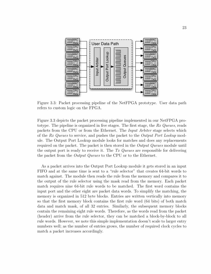
Figure 3.3: Packet processing pipeline of the NetFPGA prototype. User data pathrefers to custom logic on the FPGA.
Figure 3.3 depicts the packet processing pipeline implemented in our NetFPGA pro-totype. The pipeline is organized in five stages. The first stage, the Rx Queues, readspackets from the CPU or from the Ethernet. The Input Arbiter stage selects whichof the Rx Queues to service, and pushes the packet to the Output Port Lookup mod-ule. The Output Port Lookup module looks for matches and does any replacementsrequired on the packet. The packet is then stored in the Output Queues module untilthe output port is ready to receive it. The Tx Queues are responsible for deliveringthe packet from the Output Queues to the CPU or to the Ethernet.
As a packet arrives into the Output Port Lookup module it gets stored in an inputFIFO and at the same time is sent to a “rule selector” that creates 64-bit words tomatch against. The module then reads the rule from the memory and compares it tothe output of the rule selector using the mask read from the memory. Each packetmatch requires nine 64-bit rule words to be matched. The first word contains theinput port and the other eight are packet data words. To simplify the matching, thememory is organized in 512 byte blocks. Entries are written vertically into memoryso that the first memory block contains the first rule word (64 bits) of both matchdata and match mask, of all 32 entries. Similarly, the subsequent memory blockscontain the remaining eight rule words. Therefore, as the words read from the packet(header) arrive from the rule selector, they can be matched a block-by-block to allrule words. However, we note this simple implementation doesn’t scale to larger entrynumbers well; as the number of entries grows, the number of required clock cycles tomatch a packet increases accordingly.

24
The memory is also used to store the lookup results: the replacement data, thereplacement mask, and the hit packet and byte counters. The entries are writtenhorizontally such that each memory word contains all the data for a single match.When a match is found, the Output Port Lookup module reads the packet out of theinput FIFO, and uses the result from the match to replace the first 64 bytes (512bits) of the packet headers as required. If a match is not found, the module reads thepacket from the input FIFO and sends it to the CPU over PCI.
3.4.2 Microbenchmarks.
Table 3.2 contains latency and throughput rates for cache entry insertion and dele-tion for our NetFPGA prototype. The entry insertion is far slower because it requireswriting the full lookup entry, the header modifications, and it requires overwritingthe packet and byte counts. Deletion on the other hand simply overwrites the enablebit for the entry.
Overhead Latency Throughput
Entry insert 300 bytes 55.5 ms 18,018/s
Entry delete 4 bytes 740 ns 1,351,351/s
Table 3.2: Cache insertion/deletion performance of the NetFPGA prototype.
We also performed throughput testing for the data path using a hardware packetgenerator which can perform line speed testing of various packet sizes (Table 3.3).Tests were performed with full line rate on all four ports. Results include the EthernetCRC, the inter-packet gap, and the packet preamble.
Packet size (bytes) 64 128 512 1500
Throughput (Gbps) 3.8 3.8 3.8 3.8
Table 3.3: Throughput of the NetFPGA prototype.
3.5 Summary
In this chapter, we have presented SDF architecture, core API and prototypesin both software and NetFPGA hardware. SDF is a hybrid approach combining thesuperior flexibility of software and the high speed and low cost of hardware. In SDF,
25
all the forwarding decisions are first determined by software and then cached in hard-ware to expedite forwarding similar packets. SDF API is designed after the SocketAPI and allows packet manipulation and internal state tagging. Our prototypes sup-port the API in both C/C++ and Python. The following chapter explores a widespectrum of forwarding supported by SDF.
26
Chapter 4
SDF Use Cases
The goal of SDF is to allow software to define a wide range of forwarding behaviors,all of which can then be accelerated by the same underlying hardware. To illustratethe kinds of forwarding that can be supported, this chapter describes several usecases.
4.1 Accelerating Existing Software Routers
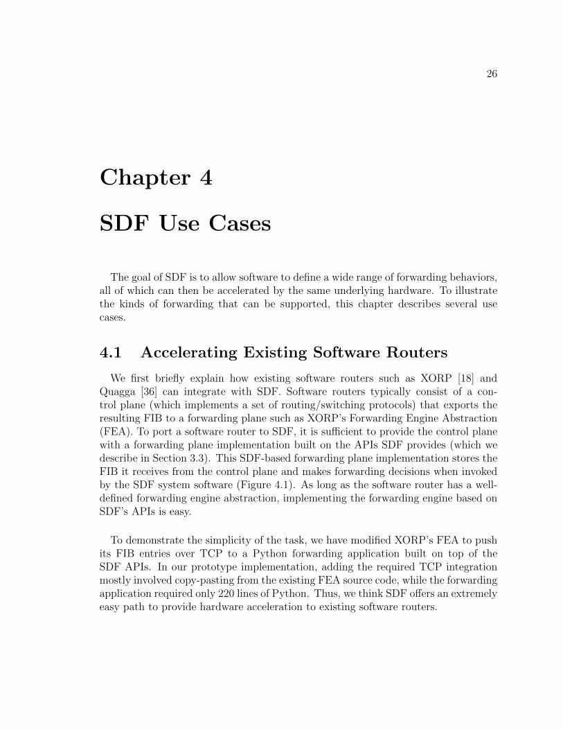
We first briefly explain how existing software routers such as XORP [18] andQuagga [36] can integrate with SDF. Software routers typically consist of a con-trol plane (which implements a set of routing/switching protocols) that exports theresulting FIB to a forwarding plane such as XORP’s Forwarding Engine Abstraction(FEA). To port a software router to SDF, it is sufficient to provide the control planewith a forwarding plane implementation built on the APIs SDF provides (which wedescribe in Section 3.3). This SDF-based forwarding plane implementation stores theFIB it receives from the control plane and makes forwarding decisions when invokedby the SDF system software (Figure 4.1). As long as the software router has a well-defined forwarding engine abstraction, implementing the forwarding engine based onSDF’s APIs is easy.
To demonstrate the simplicity of the task, we have modified XORP’s FEA to pushits FIB entries over TCP to a Python forwarding application built on top of theSDF APIs. In our prototype implementation, adding the required TCP integrationmostly involved copy-pasting from the existing FEA source code, while the forwardingapplication required only 220 lines of Python. Thus, we think SDF offers an extremelyeasy path to provide hardware acceleration to existing software routers.

27
Routing Protocols Suite
(XORP, ...)
Forwarding plane (as a Forwarding App)
Pushing FIB
Forwarding Hardware(Packet classification engine)
System Software
Proposed Architecture
Invoking for cache misses
FIB inDRAM
Control-planeactivities
DataPkts
DataPkts
Figure 4.1: Supporting an existing software router by a simple forwarding applicationimplementing the forwarding engine abstraction of the software router.
4.2 Virtualization
There is a growing research literature (see [2, 5, 39] for a small sampling) on networkvirtualization, which is the ability to run separate network architectures in paralleleach within their own “slice” of the network. These slices can implement their ownrouting and forwarding algorithms, and essentially operate as independent networks.1
To create slices, the network traffic must be partitioned in some way so that it is clearwhich packets belong to which slices. This demultiplexing criterion can be defined interms of input ports or VLANs or other fields in the packet header.
The key challenge in network virtualization is to support separate forwarding algo-rithms on the same hardware infrastructure. Note that it is simple to do so in softwareby having separate forwarding processes. When a packet arrives at a software switch,it is sent to the appropriate forwarding process based on the demultiplexing criterion,and that process then makes the forwarding decision for that packet.
1We are using the term network virtualization as it is primarily used in the research community.In the commercial world, network virtualization does not involve different forwarding algorithms butis mostly focused on sharing physical infrastructure, managing logical link topology, and supportingvirtual server mobility.

28
Initial attempts at producing the same virtualization behavior in hardware werecumbersome and expensive, involving separate network processors for each slice. Thisis because traditional hardware-based packet forwarding embeds the forwarding logicdirectly in the hardware, and it is difficult to implement several different forwardinglogics simultaneously in the same ASIC.
However, because SDF uses software for all forwarding decisions, and these deci-sions are merely imitated in hardware, supporting multiple forwarding algorithms isrelatively straightforward (as long as each forwarding algorithm individually is com-patible with the SDF forwarding model). This is because the ability to imitate aforwarding decision based on a packet header is architecture-neutral. Also, the de-multiplexing step is based on either the input port or the packet header, and thusdemultiplexing is codified in the resulting decision entry in the hardware. That is,SDF treats the demultiplexing decision as part of the overall forwarding decision.2
To do this in a manner in which each forwarding application gets its fair share ofsystem resources, the system software should segment the classification engine (e.g.,TCAM) between each of the applications. This requires either the applications betrusted to provide a unique segment ID, or for the system software to be able todetermine which application made a particular forwarding decision. Of course thisis only a first order protection measure as errant applications could still consumedisproportionate amounts of CPU or control bandwidth. Protecting against suchcases requires isolation measures, which are orthogonal to our proposal and wellunderstood by the research community (see e.g., [34]).
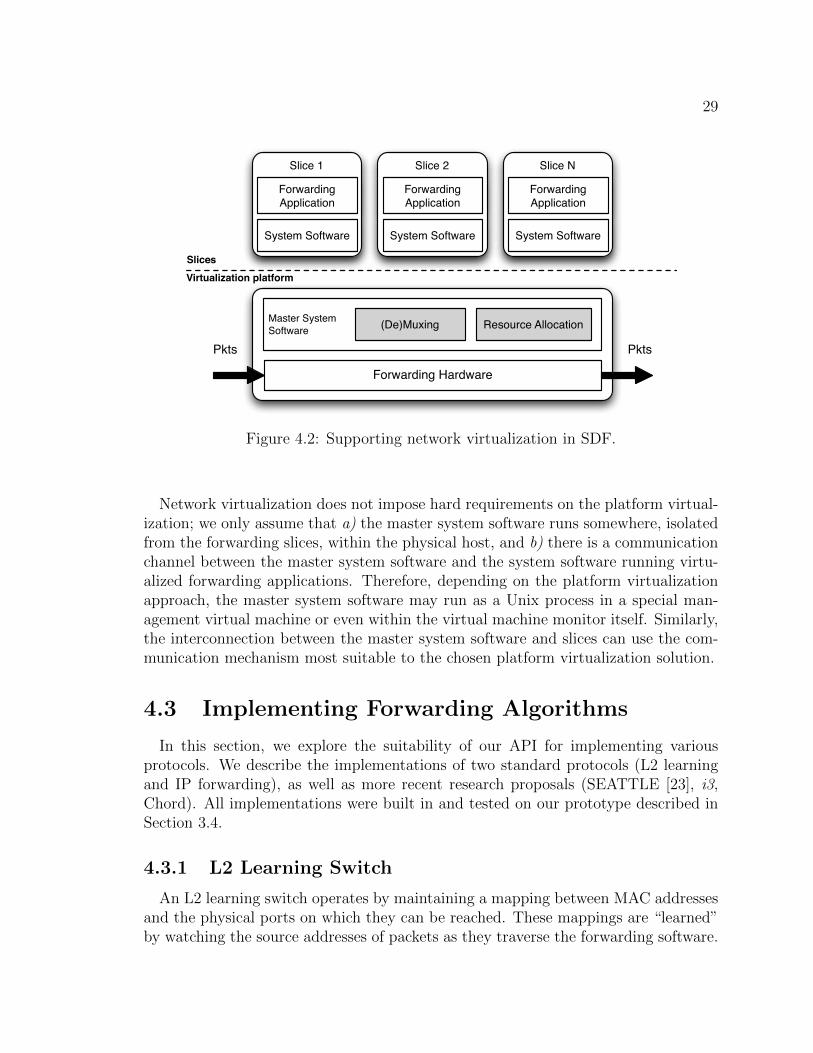
Figure 4.2 depicts our virtualization prototype based on Linux-VServer [26]. Eachforwarding application runs in its own slice, on top of a local copy of system software.These system software instances in the slices are then connected to the master sys-tem software instance in the “root” slice, which maintains a table of demultiplexingkeys (e.g., VLAN IDs) to uniquely identify the destination slice for incoming packetsrequiring a forwarding decision. The master system software is also responsible forensuring fair resource allocation. In our prototype, we assume administrator config-ures the slices, their demultiplexing key and resource allocation a priori. We haveused our prototype to run several different forwarding algorithms simultaneously, in-cluding XORP, Chord [49], i3 [48], and VL2 [12], and have achieved hardware speedsand good isolation.
2This virtualization approach is similar to FlowVisor (in the submission of SIGCOMM ’2010):these two pieces of work were done simultaneously. The FlowVisor work explores the applications ofvirtualization while the study here focuses on the software API and merely identifies virtualizationas a natural and straightforward byproduct of software-defined networking.
29
Forwarding Hardware
Master SystemSoftware
Pkts Pkts
(De)Muxing
System Software
ForwardingApplication
Slice 1
System Software
ForwardingApplication
Slice 2
Resource Allocation
Virtualization platform
System Software
ForwardingApplication
Slice N
Slices
Figure 4.2: Supporting network virtualization in SDF.
Network virtualization does not impose hard requirements on the platform virtual-ization; we only assume that a) the master system software runs somewhere, isolatedfrom the forwarding slices, within the physical host, and b) there is a communicationchannel between the master system software and the system software running virtu-alized forwarding applications. Therefore, depending on the platform virtualizationapproach, the master system software may run as a Unix process in a special man-agement virtual machine or even within the virtual machine monitor itself. Similarly,the interconnection between the master system software and slices can use the com-munication mechanism most suitable to the chosen platform virtualization solution.
4.3 Implementing Forwarding Algorithms
In this section, we explore the suitability of our API for implementing variousprotocols. We describe the implementations of two standard protocols (L2 learningand IP forwarding), as well as more recent research proposals (SEATTLE [23], i3,Chord). All implementations were built in and tested on our prototype described inSection 3.4.
4.3.1 L2 Learning Switch
An L2 learning switch operates by maintaining a mapping between MAC addressesand the physical ports on which they can be reached. These mappings are “learned”by watching the source addresses of packets as they traverse the forwarding software.

30
Learned addresses expire after some period of inactivity, and each entry is updatedwhen the switch receives a frame with the same source address through a differentport (e.g., during host movement). Incoming packets for which there is no learnedMAC address are flooded.
When a packet arrives and there is a mapping for its destination MAC address, anentry is created in the TCAM with the destination MAC address field marked as adependency. We also mark the incoming port as a dependency to ensure that we cansee packets from other hosts on the network. If the switch does not find a mapping,the cached forwarding decision is simply to broadcast the packet. In addition, torevoke the entry when the mapping changes, we annotate the forwarding decisionwith a particular state identifier associated to the mapping entry.
4.3.2 IPv4 and IPv6 Forwarding
IP forwarding proved to be a challenging forwarding algorithm to support on ourplatform. The challenges stem from both the contents of the IP header as well asfrom the complicated lookup algorithm involved, LPM.
To forward IPv6 packets, the forwarding software has to inspect the destinationaddress and modify the TTL. Thus, the dependencies are the address and TTL, andthe rewritten packet header modifies the TTL. IPv4 is more complicated, becausein addition the forwarding software must verify the IP header checksum and thenrecompute the checksum after the TTL has been modified – and therefore, it needs tomark the entire packet header as a dependency (because the entire packet header isinvolved in the header checksum recomputation). The obvious remedy is to supportchecksumming and TTL decrementing in hardware, as is currently done. This can bedone by providing some basic arithmetic primitives (decrementing, checksum, hash,etc.) that can be applied to specified sets of bits (i.e., the hardware does not have tounderstand where the TTL field is). The SDF API could be extended with these ad-ditional operation-specific calls to convey enough information to the system softwarefrom the forwarding application to imitate these operations in hardware, assumingthe forwarding hardware supports them.
LPM as a lookup algorithm is challenging for our API due to its implicit use of aconflict resolution scheme (longest match) for deciding the correct forwarding action.In our Python implementation of a simplified IPv4 router, the router pre-loads aFIB (from a RIB obtained from RouteViews [38]) and builds a trie. When it isinvoked by cache misses, it looks up the trie to figure out the next hop address. Sincethis next-hop result is valid until the FIB changes again for that entry, the softwaremarks the destination IP address and TTL, and associates the sent packet with the

31
corresponding “IP-to-next hop” mapping entry in the FIB data structure. Whenupdating the FIB, the software creates a new trie and checks whether the new trieyields the same next hop for each IP address in the old trie. If the result differs foran address, the software revokes the corresponding old entry and constructs a newone, otherwise using the old entry in the new trie. To maintain the correctness of theforwarding, the router implementation calls revoke() for all FIB entries sharing thesame prefix as the newly added prefix.
In our approach, the software is oblivious to the existence of the TCAM.3 Further,because the software is deterministically making a forwarding decision over the packetheaders, and the system software is revoking these decisions as the system statechanges, the TCAM should never contain conflicting entries. The trade-off of usingnon-conflicting entries is that there is the potential for substantial hardware stateexplosion which is generally ameliorated through the use of priorities. For example,the default entry in longest prefix match (LPM) conflicts with every other entry.In our approach, this would require every non-conflicting destination address prefixwhich matches the default route to be added as a separate hardware entry.
Although, SDF doesn’t assume the use of priorities in hardware classification rules,the system software could maintain the header bit values and the masks of cacheddecisions in an order suitable for TCAMs to reduce the number of TCAM entriesusing the following algorithm:
Step 1. First consider only decisions not having a “don’t-care” bit set in the beginningof the search mask. Assign these decisions to groups based on their longest,first consecutive exact match; the group having the longest exact match ofall will have the highest priority and the group with least exact match bitswill have the lowest priority.
Step 2. Then assign all the remaining headers (which all have a “don’t-care” bit ormore set in the beginning of their masks) to groups based on the number ofconsecutive “don’t care” bits; the decisions in a group with only one “don’t-care” bit get a priority number just below the lowest priority assigned forgroup in the step one. The group with most “don’t -care” bits gets thelowest priority of all groups processed in the steps one and two.
Step 3. Repeat steps one and two, recursively, for each group to sort the entrieswithin the group. Repeat until no cached decision has search mask bits leftfor processing.
3Modulo API calls aiding the system in tracking the header bits and internal application stateused in forwarding decisions.

32
However, this does not solve the problem of determining how to update TCAM en-tries without requiring the rewriting of all entries, which could result in relatively longperiods of time (even seconds) when TCAMs cannot be used in packet forwarding.We do not present a fast update algorithm here, but view the algorithms for per-forming incremental updates developed for IP addresses [40] and for general packetclassification [46] as excellent starting points.
4.3.3 Floodless in SEATTLE
We also implemented SEATTLE [23] within our prototype. Like i3, SEATTLEdemonstrates that our approach can support hardware forwarding speeds of nonstan-dard protocols. SEATTLE performs host discovery without resorting to flooding [23].It does so by forming a link-layer DHT, that stores information about host locations(i.e., associated switches), IP addresses, and MAC addresses. Briefly, when a switchS1 detects a directly connected host H1, it learns H1’s MAC address and IP addressfrom traffic and publishes the IPH1 → (MACH1
, S1) and the MACH1 → S1 mappingsin the DHT. When a remote host H2 then sends a packet to H1, H2’s local switch S2
resolves H1’s address and location through the DHT, and tunnels the packet to S1
on behalf of H2. If the mapping changes (e.g., host migration or NIC replacement),S1 performs DHT operations to update the mapping.
We limit the description of our implementation to location resolution since addressresolution is handled in a similar manner in SEATTLE. On receipt of an Ethernetframe from a host, our Python forwarding software first publishes the “MACSRC →Switch” mapping if the address has not been published before. Next, if it finds anentry in its local mapping table, it sends the frame to the cached location (i.e., theassociated switch) via the shortest path. To do so, the switch encapsulates the frameby sending it out of a logical port which maintains a tunnel to the destination switch.The software marks the destination MAC of the received packet as a dependencythereby ensuring that the decision remains cached until the mapping changes.
If there is no mapping entry found, the forwarding software initiates the DHTlookup process, and marks the destination address in the packet header as a depen-dency; then the software sends the packet to a special “null port”; this caches thedecision to drop frames destined to the address. This decision is also annotated withstate identifiers corresponding to the (pending) mapping lookup sent to the DHT;once the DHT reply arrives (or software timeouts while waiting for it), the cacheddecision will be revoked. On receipt of a DHT message, our SEATTLE implementa-tion performs the appropriate DHT operation (i.e., insert, delete, lookup). Note thatsince DHT messages are control messages, they are not subject to caching.

33
Finally, when the software receives an outer frame, it inspects the encapsulatingheader to determine whether it requires further forwarding or not. If the framerequires forwarding, it marks the destination address of the outer header and forwardsthe packet further without en/decapsulation. Since this decision is valid until theswitch topology changes, the sent frame is annotated by the relevant entries in thedata structure holding the information about switch topology. If the frame does notrequire forwarding to another switch (i.e., the frame is addressed to the switch itself),the switch marks the destination address of the encapsulating header and sends theframe to a “decapsulation port” (coupled to the actual physical output port connecteddestined to a host) removing the encapsulation header before sending the packet outon the wire. Forwarding the packet to the decapsulation port signals the systemsoftware to include hardware-implemented decapsulation in the cached decision.
4.3.4 i3 and Chord
We used our prototype to implement another non-standard design, i3 (InternetIndirection Infrastructure) [48]. In i3 servers register listeners (i.e. triggers) in thenetwork and obtain trigger identifiers, which they publish to allow senders to findthem. In our implementation, trigger identifiers are published in a DHT for whichwe used Chord [49]. To send a packet to a server registered with i3, the sender looksup the server in the DHT by traversing Chord’s node ring until it finds the server’strigger identifier, which it can use to forward the packet to the trigger. The triggerthen forwards the packet to the server.
We have implemented both Chord and i3 forwarding on SDF. This required match-ing packet headers below the transport layer at the Chord and i3 layers, demonstratingthe flexibility of the SDF approach. Both Chord and i3 forwarding require only exactmatches on their respective identifier fields. Specifically, Chord’s cached decisionsinclude the 8 bit packet type field, the 160 bit Chord identifier, and the 8 bit ChordTTL. For i3, the cached decisions include the 32 bit identifier stack size (the numberof stacked identifiers) and a 256 bit i3 identifier. The required TCAM search masklength is therefore well beyond the standard maximum of 576 bits.
4.4 Summary
This chapter has demonstrated SDF’s flexibility in forwarding algorithms by im-plementing the following forwarding examples on top of the proposed architecture:a) accelerating XORP software router, b) network virtualization, c) classical L2/L3forwarding and d) more recent i3 and SEATTLE. In the following chapter, we presentthe performance study result of SDF.

34
Chapter 5
SDF Performance Study
Our design contains both a software component (the forwarding application andthe system software, running on a general CPU) and hardware component (based ona classification engine, in our case a TCAM). If the system is run in proactive mode,and the hardware can store enough state to capture all possible forwarding decisions,then the system will run at hardware forwarding speeds. This is how we imagine thesystem will be run in performance-critical scenarios (such as the Internet backbone).If the system is run in reactive mode, as would be appropriate for most experimentaluses where performance is not critical but a simple and convenient programmaticAPI is essential, then the resulting speed depends on how many packets are handledby software, and the relative speed of the hardware and software forwarding actions.This is our focus in this chapter.
5.1 Assumption
While the ability of commodity CPUs to perform packet forwarding has increasedsignificantly over the last few years, TCAMs remain significantly faster. For example,an 8-core PC supports forwarding capacities of 4.9 million packets/s [11], while mod-ern TCAMs can achieve rates of 150–200 million packets/s.1 Even special purposegeneral processors which include network hardware on die (e.g. [7]) are an order ofmagnitude slower than TCAMs.
In order to marry a slower software path with a much faster hardware path in amanner that takes full advantage of the system, the ratio of the number of packetsprocessed by hardware versus software must be commensurate with the differential
1The classification rate largely defines the maximum hardware forwarding speed since applyingpacket modifications is easier than classification. Similarly, the high-speed switch fabric connectingports is not a limiting factor.
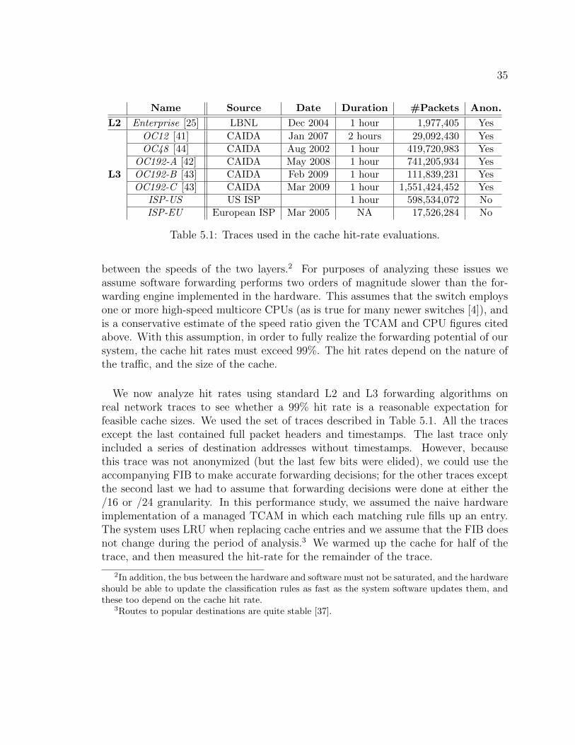
35
Name Source Date Duration #Packets Anon.
L2 Enterprise [25] LBNL Dec 2004 1 hour 1,977,405 Yes
L3
OC12 [41] CAIDA Jan 2007 2 hours 29,092,430 YesOC48 [44] CAIDA Aug 2002 1 hour 419,720,983 Yes
OC192-A [42] CAIDA May 2008 1 hour 741,205,934 YesOC192-B [43] CAIDA Feb 2009 1 hour 111,839,231 YesOC192-C [43] CAIDA Mar 2009 1 hour 1,551,424,452 Yes
ISP-US US ISP 1 hour 598,534,072 NoISP-EU European ISP Mar 2005 NA 17,526,284 No
Table 5.1: Traces used in the cache hit-rate evaluations.
between the speeds of the two layers.2 For purposes of analyzing these issues weassume software forwarding performs two orders of magnitude slower than the for-warding engine implemented in the hardware. This assumes that the switch employsone or more high-speed multicore CPUs (as is true for many newer switches [4]), andis a conservative estimate of the speed ratio given the TCAM and CPU figures citedabove. With this assumption, in order to fully realize the forwarding potential of oursystem, the cache hit rates must exceed 99%. The hit rates depend on the nature ofthe traffic, and the size of the cache.
We now analyze hit rates using standard L2 and L3 forwarding algorithms onreal network traces to see whether a 99% hit rate is a reasonable expectation forfeasible cache sizes. We used the set of traces described in Table 5.1. All the tracesexcept the last contained full packet headers and timestamps. The last trace onlyincluded a series of destination addresses without timestamps. However, becausethis trace was not anonymized (but the last few bits were elided), we could use theaccompanying FIB to make accurate forwarding decisions; for the other traces exceptthe second last we had to assume that forwarding decisions were done at either the/16 or /24 granularity. In this performance study, we assumed the naive hardwareimplementation of a managed TCAM in which each matching rule fills up an entry.The system uses LRU when replacing cache entries and we assume that the FIB doesnot change during the period of analysis.3 We warmed up the cache for half of thetrace, and then measured the hit-rate for the remainder of the trace.
2In addition, the bus between the hardware and software must not be saturated, and the hardwareshould be able to update the classification rules as fast as the system software updates them, andthese too depend on the cache hit rate.
3Routes to popular destinations are quite stable [37].

36
5.2 L2 learning
Our MAC learning implementation uses 15 second timeouts. For analysis, wehave used the first trace in Table 5.1, and the resulting cache hit rates are shown inFigure 5.1.
0.0001
0.001
0.01
0.1
1
16 32 64 128 256
Mis
s r
ate
(lo
g s
ca
le)
The number of cache entries (log scale)
L2 switch
Figure 5.1: Simulations of cache miss rates for L2 learning with the enterprise trace.
The cache miss rate is less than 1% for cache sizes larger than 64, and is nearly0.01% for a cache with 256 entries. Note that these TCAM state sizes are significantlysmaller than today’s commercial Ethernet switches, which commonly hold 1 millionEthernet addresses (6MB of TCAM). Thus, using our approach in reactive modewould easily reach the requisite 99% hit rate with very moderate state requirementsin this particular enterprise setting. We have looked at other enterprise traces, andfound similarly encouraging results.
5.3 IPv4 forwarding
We next explore the cache behavior of standard IPv4 forwarding, assuming thatthe hardware supports TTL decrementing and checksum recomputation (so the for-warding decision depends only on the destination address). We had two traces withassociated FIBs, which are the ISP-US trace and ISP-EU in Table 5.1. In order toobtain conservative results, we used no warm-up period, so every cache entry experi-ences at least one miss. The cache hit rates of this analysis are shown in Figure 5.2.
There are three curves: one assuming that the forwarding decisions are based onthe FIB, one assuming that the forwarding decisions are based on /16 prefixes, andone assuming that the forwarding decisions are based on /24 prefixes. For now wefocus on the FIB-based curve, since that represents what would happen in practice.Here, the miss rate is less than 1% when the cache holds more than about 16K entriesfor the ISP-US trace and 64k entries for the ISP-EU trace, which is a small amountof state for an ISP-class router.

37
0.00001
0.00010
0.00100
0.01000
0.10000
1.00000
8K 16K 32K 64K 128K
Mis
s ra
te (l
og s
cale
)
The number of cache entries (log scale)
LPM/16/24
0.001
0.010
0.100
1.000
10K 20K 40K 100K 200K 400K
Mis
s r
ate
(lo
g s
ca
le)
The number of cache entries (log scale)
LPM/16/24
Figure 5.2: Cache miss rates for ISP-US trace (top) and ISP-EU trace (bottom).
We do not know the link’s speed for these traces, so to investigate hit-rates onvery high-speed links we used several traces from CAIDA. For these traces we did nothave an associated FIB (because the traces were anonymized); we therefore measuredthe hit-rates assuming that the forwarding decisions were done on either a /16 or /24granularity. The data from the ISP traces indicate that, in that example, the /16granularity is a better estimate of the hit rate, and that the /24 granularity is veryconservative (roughly two orders of magnitude higher miss rate than the FIB resultsfor large caches).
Figure 5.3 shows the results for the OC-48 trace and the OC-192C trace (the resultsfor the other OC-192 traces are qualitatively similar). When using /16 forwarding,even tiny cache sizes (2k entries for OC-48 and 1k entries for OC-192; the 1k point liesoff the graph in Figure 5.2) are sufficient to achieve 1% miss rates. For /24 forwarding(which the ISP trace suggests is a very pessimistic estimate), cache sizes of 20k entriesand 40k entries are required for 1% miss rates, which is again quite reasonable for ISP-class routers. If these traces are representative, these results suggest only moderate-sized caches are needed to achieve sufficiently high cache hit rates in both enterpriseand ISP networks.

38
1e-06
1e-05
0.0001
0.001
0.01
0.1
1
1K 2K 4K 10K 20K 40K 100K
Mis
s r
ate
(lo
g s
ca
le)
The number of cache entries (log scale)
/16/24
1e-06
1e-05
0.0001
0.001
0.01
0.1
10K 20K 40K 100K 200K 400K
Mis
s r
ate
(lo
g s
ca
le)
The number of cache entries (log scale)
/16/24
Figure 5.3: Cache miss rates with forwarding on the /16 and /24 granularities for theOC-48 (top) and the OC192-C trace (bottom).
5.4 Performance under stressful conditions
We now discuss two situations where caching’s performance may get stressed: whenthe software FIB changes and when the switch is under attack. First, when the FIBchanges, this will change a large number of forwarding entries. In traditional flowcaching, this requires flushing the cache and enduring a high miss rate until the cacheis warmed up again. However, in our approach, when the routing state changes, theapplication can push updated decisions to the hardware after revoking the invaliddecisions, rather than merely revoking them. This does require a fast channel toupdate the hardware component, which may be the limiting factor, but there is noneed for a long cache warmup period after a routing event.
Second, in a denial-of-service attack, attackers can inject spurious traffic in thehope of dislodging valid cache entries, which would increase the miss rate. Once themiss rate goes over 1% (assuming the two order of magnitude difference between linespeeds and the CPU), then some of the cache-miss packets will be dropped. We

39
0.001
0.01
0.1
10K 20K 40K 100K 200K 400K
Mis
s r
ate
(lo
g s
ca
le)
Cache sizes (log scale)
w/o attackw/ attack
0.0001
0.001
0.01
0.1
1
0 0.1 0.2 0.3 0.4 0.5 0.6 0.7 0.8 0.9
Mis
s ra
te (l
og s
cale
)
The ratio of DoS traffic to total traffic
16K entries64K entries
Figure 5.4: Cache miss rates with (and without) random DoS traffic comprising 50%of the traffic for the ISP-EU trace (top). Cache miss rates with random DoS trafficfor the ISP-US trace (bottom).
now investigate how effective such an attack might be, assuming the cache uses aleast-recently-used cache replacement policy.4
Using the ISP-US trace and ISP-EU trace in Table 5.1 (again, with no warm-up period), we examine the effect of a DoS attack that sends traffic with randomdestinations. The top graph in Figure 5.4 compares the miss rate with no attackto the miss rate when the attack traffic comprises half of the total traffic. Withan attack of this magnitude, overloading the link is likely to be more of a problemof cache misses, but we wanted to look at an extreme scenario. Somewhat to oursurprise, this massive attack only has a very limited impact on the miss rate; thisis because the long-tailed distribution of network destinations makes it unlikely thatany of the frequently used cache entries is ever evicted. In fact, for the larger cachesizes, the miss rate with the attack traffic is lower than without the attack traffic
4The network can take more explicit measures against such attacks, such as rate-limiting thenumber of new flow entries from any port, which would limit the scope of such an attack. Howeverhere we just focus on the attack traffic’s impact on the cache miss rate.

40
(this is because the random addresses tend to fall on the large prefixes, whereas thetrace traffic more systematically explores the address space). Another experimentusing the ISP-US trace shows a consistent result (the bottom graph in Figure 5.4)that random denial-of-service attack only has limited impact on cache performance.
5.5 Summary
This chapter has evaluated SDF under a conservative assumption that slowersoftware components perform two orders of magnitude slower than hardware. Thus,to keep up with the hardware speed the hit rates of decision caching must exceed99%. Our experiments based on real packet traces have shown that SDF would easilybe able to achieve the 99% hit rates goal. In addition, our experiments have indicatedthat stressful conditions like denial-of-service attacks might have only limited impacton cache performance due to high skewness in address access patterns.
We do not claim to have solved all performance problems associated with caching.However, if caching is mainly used in environments where performance is not critical,then these issues discussed above (and other performance issues) may not be fatal.While the proactive mode is clearly safer, the reactive mode may still be an attractivechoice considering how small the state requirements are to achieve low miss rates.

41
Chapter 6
Ripcord: Platform for Data CenterRouting and Management
This chapter presents a new platform, called Ripcord, for data center routing andmanagement. Ripcord provides a uniform, high-level interface to an underlying phys-ical network so that a data center can free itself from a particular solution tightlycoupled with its physical network, and have flexibility in routing and management.Ripcord enables to quickly prototype new data center network solutions, and (per-haps more interestingly) to run several schemes simultaneously on the same physicalnetwork. A researcher may use this capability to evaluate two schemes side by side;an experimental data center can host multiple researchers at the same time; a multi-tenant hosting service may provide different customers with different networks; and amulti-service data center may use schemes optimized for different services (e.g., onescheme for map-reduce, alongside another for video streaming).
In the following section, we briefly review core criteria on which data center net-working solutions focus. Then, Section 6.2 describes Ripcord’s architecture to sup-port the key criteria, followed by our prototype implementation in Section 6.3. InSection 6.4, we illustrate the generality of Ripcord by implementing recent data centerproposals (e.g., VL2 [12] and PortLand [32]) and running them in tandem in software,and individually in both software and on a test data center made from commercialhardware. We present their performance comparison in Section 6.5 and conclude thechapter.
6.1 Overview
This section outlines Ripcord’s high-level design decisions after describing designrequirements at which Ripcord targets, and challenging criteria that a data centernetworking platform must address. In the next section, we describe the Ripcord’s
42
design in greater detail.
6.1.1 Design Requirements
Ripcord’s design follows directly from four high-level design requirements: a) Thesystem must allow researchers to prototype quickly, with minimum interference fromthe platform itself. b) Ripcord must allow experimenters to evaluate a new scheme,and c) compare it side-by-side with others. d) Finally, it must be easy to transferand deploy a new scheme to physical hardware.
6.1.2 Key Criteria for Data Center Networking
If we are to help experimenters evaluate and compare different schemes, we needto understand the main criteria they will use, and how a platform housing thoseschemes support the criteria. Based on recent proposals [12, 32] (and the needs ofdata centers) the most challenging criteria are:
• Scalability : Large data centers scale to thousands of servers or millions of vir-tual machines (VMs). The experimenter will need ways to compare topologies,routing and addressing schemes and their consequences on forwarding tablesand broadcasts.
• Location Independence: Dynamic resource provisioning in data centers is muchmore efficient if resources can be assigned in a location-agnostic manner andVMs can migrate without service-interruption. Ripcord must support routingthat operates at different layers, and novel addressing schemes.
• Failure Management : Scale-out data centers are designed to tolerate networkfailures. Ripcord must provide a means to inject failures to links and switches,to explore how different schemes react.
• Load balancing : Data centers commonly spread load to avoid hotspots. Ripcordmust enable randomized, deterministic and pre-defined load-balancing schemes.
• Isolation and Resource Management : If multiple experiments are to run simul-taneously - just as multiple services run concurrently in a real data center -Ripcord must isolate one from another.
6.1.3 Ripcord’s Design Principles
The requirements and criteria presented above have led to the following high-levelapproach. The next section explores the design in details.

43
• Logically centralized control: At the heart of Ripcord is a logically central-ized control platform. Ripcord’s centralized approach reflects a common trendin recent proposals (e.g., VL2’s directory service, PortLand’s fabric manager).While logically centralized, Ripcord can scale by running several controllers inparallel.
• Multi-tenant: In Ripcord, each “tenant” manages a portion of the data centerand controls routing. A tenant can be a real customer sharing the data center,an experiment requiring a separate management and/or routing control, or evena service (e.g., MapReduce job or content delivery). Ripcord supports multipletenants concurrently by managing the resources they use in the network andenforces resource isolation between tenants.
• Modular: The central platform is modular and includes a collection of librarycomponents to facilitate code re-use and fast prototyping. Its capability canbe extended by simply adding library modules (e.g., DHCP module, firewallmodule, etc), and Ripcord users may share modules to quickly prototype newrouting/management schemes. Tenants can also select among a variety of rout-ing schemes, arranged as modules connected in a pipeline.
6.1.4 Prototype
Our Ripcord prototype builds upon and replaces the default applications of NOX [16].NOX is a logically centralized platform for controlling network switches via the Open-Flow [28] control protocol. We summarize NOX and OpenFlow briefly in the ap-pendix. We have chosen these particular technologies because they provide a cleanvendor-agnostic abstraction of the underlying network, and NOX provides a well-defined API to control the network as a whole. In principle, however, our prototypecould be built on any network control abstraction offering the set of events and com-mands listed in Table 6.1 and Table 6.2.
Events Semantics
SWITCH JOIN Switch joined network.
SWITCH LEAVE Switch left network.
PACKET IN Packet without matching flows came in.
STATS REPLY Flow stats are available.
Table 6.1: Network events that Ripcord expects from switch.

44
Commands Semantics
FLOW MOD Installs/removes flows.
PACKET OUT Sends out a given packet.
STATS REQUEST Polls flow stats.
Table 6.2: Switch commands expected by Ripcord.
6.2 Design
To help orient the reader we use an example walkthrough as a a high-level intro-duction to key components in the system. The following steps describe how Ripcordhandles incoming flows by passing them to the correct tenant for routing and setupin the network.
6.2.1 Example Walkthrough
Configuration phase. The first step in the deployment of a Ripcord data centeris to provide the “Configuration and Policy Database” with the particulars of thenetwork. This includes topology characteristics (e.g., FatTree, Clos, etc), the tenants,and a mapping from the tenants to the available routing applications (e.g., PortLand,VL2, etc).
Startup phase. The “App Engine”, “Routing Engine” and “Topology Engine”are instantiated based on administrative information fed to the Configuration andPolicy Database. At this point, optional network bootstrap operations (e.g. proactiveinstallation of flows) are carried out. In addition, the Routing Engine and the AppEngine register to receive notification on each incoming flow.
Running phase. In this phase, Ripcord listens for incoming routing requests.These requests are generated as events by switches each time they receive a packetfor which there is no existing flow table entry. When Ripcord receives the routingrequest it makes sure that the packet is either processed by a responsible (per-tenant)“Management App” and its routing pipeline or discarded. The sequence of steps forhandling routing requests is outlined below:
Step 1. When a switch receives a packet for which there is no matching flow-tableentry it creates a routing request containing the packet and notifies the“Authenticator-Demultiplexer”.
Step 2. The Authenticator-Demultiplexer, receives the routing request, tags it withthe identifier of the tenant that should handle it, and, if the routing request islegitimate, notifies the “App Engine”. If the routing request is not legitimate

45
(e.g., it would result in traffic between isolated networking domains), it isdenied and the packet is discarded.
Step 3. The App Engine dispatches routing requests to the point of contact associatedwith each tenant – its “Management App”. The Management App determineswhether it should discard the incoming packet, process it (e.g., to handlecontrol requests like ARP), or propagate the request to the “Routing Engine”.
Step 4. When the Routing Engine receives the routing request it invokes the tenant’spredefined routing pipeline, which computes a route and then the RoutingEngine informs the “Flow Installer”.
Step 5. Finally, the Flow Installer sends out commands to select switches, along thepath inserting flow entries in their tables thus establishing the new flow onthe selected path.
Monitoring phase. Under normal operation, the Monitoring module tracks switchesas they join or leave the network. With “always-on” passive monitoring, the networkis constantly supervised for abnormalities. If an aberrant behavior is detected, theoperator can invoke active monitoring commands to delve into the problem and trou-bleshoot.
6.2.2 Components
Figure 6.1 depicts Ripcord’s high-level architecture. It consists of the followingseven components:
Configuration & Policy DB. This component is a simple storage for platform-level configuration and data center policy information. Administrators configure theDatabase with global network characteristics as well as tenant-specific policies. Thiscentralized configuration provides ease of management. As this module merely storesthe configuration, the actual policy enforcement is delegated to other componentssuch as Authenticator-Demultiplexer (explained below).
Topology Engine. This component maintains a global topology view by trackingSWITCH JOIN as well as SWITCH LEAVE events. This allows for real-time network vi-sualization, expedites fault-detection and simplifies troubleshooting. The componentalso builds per-tenant logical topology views which are used by App and RoutingEngines when serving a specific tenant.

46
PhysicalDC Network Programmable Switches
Authenticator &Demultiplexer
App Engine
Tenants
Monitor
Topology Engine
RawTopo DB
LogicalTopoViews
Routing Engine
Routing Pipelines
FlowInstaller
Flow In
Flow In
Flow Out
SWITCH_JOINSWITCH_LEAVEPACKET_IN
SWITCH_JOINSWITCH_LEAVE
STATS_REQSTATS_REP
Event flowCommand
FLOW_MODPACKET_OUT
Config &Policy
DB
Topo Update
Figure 6.1: Ripcord architecture and event flow diagram
Authenticator-Demultiplexer. It performs admission control and demultiplexesto the correct application. Upon receipt of a PACKET IN event, it invokes the Configu-ration/Policy DB and resolves the tenant in charge of the packet. If the packet is notlegitimate, the component drops it. Otherwise, it passes on the routing request tothe App and Routing Engines, as a FLOW IN event tagged with the packet and tenantinformation.
App Engine. Each tenant can have its own management app. Hence, managementapp can be seen as a centralized controller for a particular tenant. This componenttypically inspects incoming packets in a FLOW IN event and updates its internal state.For example, PortLand’s fabric manager can be implemented as a management appon Ripcord. On receipt of a FLOW IN event, the App Engine dispatches the event toa proper app based on tenant information associated with the event.
Routing Engine. This module calculates routes through a multi-stage process:starting as a loose source route between the source-destination pair, a path is gradu-ally filled through each of the routing pipeline stages. One pipeline stage may consistof zero or more routing modules. Ripcord does not limit the size of routing pipeline.It does, however, enforce the order of stages so as to help verify routing modules’composability. Table 6.3 describes these stages.

47
Routing Stage Description
TweakSrcDst The source/destination information is altered at this stage.This is usually for the purpose of loadbalancing among hosts.
InsertWayPoints This stage inserts particular switches or middleboxes to traverse (e.g.for security reasons)
Loadbalance This stage can alter a loose source route computed so far to loadbalanceamong switches and links.
ComputeRoute This stage completes route(s). If previous stages generated multipleroutes, this stage selects a final one.
TriggerFlowOut This stage triggers Flow Out event with the computed route.
Table 6.3: Ripcord’s routing pipeline stages. Earlier stages in the table cannot appearlater in routing pipeline. Each routing module should be in one of these stages.
This small routing module is far easier to verify and manage than a larger, all-in-one routing algorithm package. At the same time, it gives great flexibility asthe routing algorithm is not predetermined, but defined by the arrangement of therouting modules. Hence, new routing algorithms can be easily deployed as long asthe underlying topology supports them. One can, for instance, shift from shortest-path to policy-based routing merely by replacing one of its routing modules in the“ComputeRoute” stage. The routing pipeline for each Ripcord tenant is configuredin the Configuration/Policy DB as a list of routing modules. We envision that opensource developers will contribute routing modules and datacenter administrators willevaluate new routing algorithms on Ripcord.
Flow Installer. This component is in charge of translating FLOW OUT event intohardware-dependent control message to modify the switch flow table (e.g., OpenFlowmessage). We introduce this indirection layer to make Ripcord independent of aparticular switch control technology.
Monitor. Monitor component provides support for passive and active statisticscollection from network elements. Passive collection periodically polls switches foraggregate statistics, while active collection is targeted to probe a particular flow inthe network. When a switch joins the network, the component records its capabilities(e.g., port speeds supported) and then maintains a limited history of its statistics“snapshots”. Snapshots contain aggregate flow statistics (e.g., flow, packet and bytecounts for a switch), summary table statistics (e.g., number of active flow entries andentry hit-rates), port statistics (e.g., bytes/packets received, transmitted or dropped)and their changes since the last collection.

48
6.3 Implementation
Our Ripcord prototype consists of a technology-independent core library (imple-menting the seven components explained in Section 3.2), and NOX-dependent wrap-per code. It totals 6,988 lines of Python code plus NOX’s standard library.
6.3.1 Configuration & Policy Database
When Ripcord starts, this module reads a directory of configuration files describingthe configuration and policy, expressed as key-value pairs. The configuration languageis described in JSON because of its ability to richly express dictionary and arraytypes. New configurations can be loaded dynamically via command line arguments,for example to instantiate a new tenant or debug a running system. The policydatabase needs to be quite general: For example, an administrator might set a policysuch as ‘Packets sent from the host with MAC address A to the host with IP addressB should be routed by tenant Y’. The policy may be based on any combination of thefollowing fields: the unique ID of the switch the packet was received at, the incomingport on that switch, source MAC and IP addresses, and destination MAC and IPaddresses.
6.3.2 Topology Engine
When Ripcord starts, this module loads the topology from a configuration file. Weassume the topology is known in advance, has a regular layered structure (e.g. tree,multi-root tree, fat-tree, Clos, etc), and is relatively static. Each layer is assumedto consist of identical switches; but the number of layers, ports and link speeds mayvary. The regular structure makes it quick and easy for the routing engines to traversethe topology. Routing engines may view the entire topology, or be restricted to viewonly the part of the topology they control. The module has APIs to filter by layeror power status, or return the physical port numbers connecting two switches. SeeFigure 6.4 and Figure 6.5 below for examples of pre-existing Ripcord topologies.
6.3.3 Authenticator-Demultiplexer
When Ripcord starts, this module builds a lookup table from the Configurationand Policy Database, to map incoming traffic to the correct tenants. The processis triggered by a new PACKET IN event when a switch doesn’t recognize a flow. TheAuthenticator-Demultiplexer generates a FLOW IN event and hands the App Engine atenant ID identifying which tenant(s) to alert.
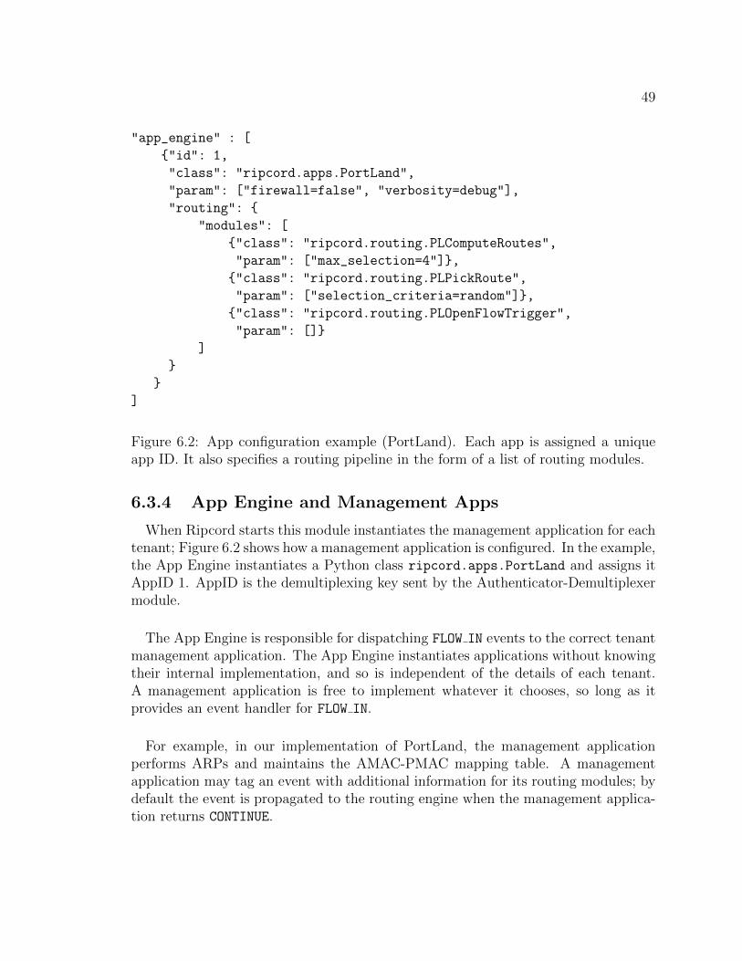
49
"app_engine" : [
{"id": 1,
"class": "ripcord.apps.PortLand",
"param": ["firewall=false", "verbosity=debug"],
"routing": {
"modules": [
{"class": "ripcord.routing.PLComputeRoutes",
"param": ["max_selection=4"]},
{"class": "ripcord.routing.PLPickRoute",
"param": ["selection_criteria=random"]},
{"class": "ripcord.routing.PLOpenFlowTrigger",
"param": []}
]
}
}
]
Figure 6.2: App configuration example (PortLand). Each app is assigned a uniqueapp ID. It also specifies a routing pipeline in the form of a list of routing modules.
6.3.4 App Engine and Management Apps
When Ripcord starts this module instantiates the management application for eachtenant; Figure 6.2 shows how a management application is configured. In the example,the App Engine instantiates a Python class ripcord.apps.PortLand and assigns itAppID 1. AppID is the demultiplexing key sent by the Authenticator-Demultiplexermodule.
The App Engine is responsible for dispatching FLOW IN events to the correct tenantmanagement application. The App Engine instantiates applications without knowingtheir internal implementation, and so is independent of the details of each tenant.A management application is free to implement whatever it chooses, so long as itprovides an event handler for FLOW IN.
For example, in our implementation of PortLand, the management applicationperforms ARPs and maintains the AMAC-PMAC mapping table. A managementapplication may tag an event with additional information for its routing modules; bydefault the event is propagated to the routing engine when the management applica-tion returns CONTINUE.

50
6.3.5 Routing Engine and Per-tenant Routing Pipeline
"default": {
"routing": {
"expandable": true,
"modules": [
{"class": "ripcord.routing.FixSwitch",
"param": [],
"mandatory": true},
{"class": "ripcord.routing.InsertMB",
"param": ["10.0.0.2", "10.0.0.3"],
"mandatory": true}
]
}
}
Figure 6.3: Global routing policy example.
The Routing Engine is responsible — for each tenant — for passing FLOW IN
events to the correct sequence of routing modules (based on the AppID). When Rip-cord starts, the module generates a pipeline for each tenant from the configurationdatabase. For example, Figure 6.2 shows how a pipeline of three routing modules isdefined for PortLand. The name of each routing module is its Python class name sothat the routing engine can correctly locate the module. The routing pipeline can beof any length, although each routing module must be in one of the routing stages inTable 6.3 and follows the order of routing stages as described in Section 3.2. Eachstage invokes associated routing modules to progressively complete a source route.The last stage triggers FLOW OUT to convert the computed source route into a seriesof flow entries and to program switches.
In addition to per-tenant routing pipelines, the data center operator may want toimpose global routing constraints. For example, traffic for all tenants may be forcedto pass through a firewall; or, each tenant may be required to run on isolated paths.Ripcord represents these constraints by a global routing policy. For instance, thepolicy represented in Figure 6.3 means that an application can define its own routingpipeline (i.e., expandable), but is subject to two mandatory routing modules.

51
6.3.6 Monitoring Implementation
The Monitoring module listens for SWITCH JOIN/SWITCH LEAVE events, and period-ically collects switch-level aggregate statistics, flow table statistics and port statistics.The module maintains statistics in the same time frame as a “snapshot” (Table 6.4)so that operators can detect and debug networking anomalies.
Fields Semantics
dpid switch idcollection epoch collection cycleepoch delta distance from previous cyclecollection timestamp time capturedports active number of active portsnumber of flows flows currently activebytes in flows size of active flowspackets in flows packets in active flowstotal rx bytes total bytes receivedtotal tx bytes total bytes transmittedtotal rx packets dropped receive dropstotal tx packets dropped transmit dropstotal rx errors receive errors (frame,crc)total tx errors transmit errorsdelta rx bytes change in bytes receiveddelta tx bytes change in bytes transmitteddelta rx packets dropped change in receive dropsdelta tx packets dropped change in transmit dropsdelta rx errors change in receive errorsdelta tx errors change in transmit errors
Table 6.4: Information included in a monitoring snapshot.
The module keeps snapshot histories, and operators can tune how the history ismanaged (e.g., the size of the history, collection frequency and the location of oldsnapshots) through the Configuration/Policy Database module. In addition, themodule also provides an API for “active” statistics collection, for detailed metricsof a particular switch or a flow (Table 6.5). Hence, it can be used to build high-levelmodules to visualize the entire network or for troubleshooting.
6.3.7 Flow Installer
When the route for a particular flow has been decided, the switches need to beprogrammed. The Flow Installer module takes FLOW OUT events, and generates binaryOpenFlow control packet(s) which are passed to NOX for delivery to the correct

52
Functions Description
get all switch stats(swid) returns all snapshots for a switchget latest switch stats(swid) returns last snapshot for a switchget all port capabilities(swid) returns the port capability map for SWget port capabilities(swid,port id) returns capabilities of a specific portget flow stats(swid, flow spec) returns specific flow statistics
Table 6.5: API exposed by the monitoring module for active statistics collection.
switches. The FLOW OUT event includes the <header match, action> pair for eachswitch the flow traverses.
6.3.8 Virtual-to-Physical Mapping
When we have a working implementation in software, we need to transfer it tohardware. Ideally, we would have access to a huge network of switches each withlarge numbers of ports. Given this is unlikely, we can slice a physical switch intomultiple “virtual” switches. Some OpenFlow switches can be sliced by physical port.For example, a k=4 three layer Fat Tree, which requires twenty 4-port virtual switches,can be emulated by two 48-port physical switches and a number of physical loopbackcables. Unfortunately, not every OpenFlow switch supports slicing.
Instead, we chose to slice switches at the controller, by implementing a virtual-to-physical mapping layer between Ripcord components and the NOX API. Sincein Ripcord the base topology is known in advance, the mapping can be staticallydefined. The result is that Ripcord routing engines and applications use virtualaddresses, while NOX sees physical addresses. For example, when a switch connects,it has an ID that must be translated from physical to virtual, which may cause onephysical switch join event to become multiple virtual switch join events. Almostevery OpenFlow message type must undergo this virtual-physical translation in bothdirections, including flow modifications, packet ins, packet outs, and stats messages.In many ways the slicing layer resembles FlowVisor [45] which also sits between theswitch and controller layers.
Ripcord’s slicing layer has been used to build k=4, 80-port Fat Trees from a rangeof hardware configurations, including two 48-port switches, one 48-port switch andtwo 24-port switches, and even from eight 4-port switches combined with a 48-portswitch, for the testbed described in Section 6.5.

53
6.4 Case studies
To illustrate Ripcord’s generality, we have implemented three data center routingalgorithms on Ripcord: Proactive L2 routing, VL2 and PortLand. As a metric ofcomplexity, Table 6.6 reports the lines of code needed for each implementation.1 Therest of this section details how we have implemented the routing schemes.
Implementation Lines of code (Python)
Proactive L2 200
VL2 576
VL2 w/ middlebox traversal 616
PortLand 627
Table 6.6: Lines of code of sample routing implementation
6.4.1 Proactive L2 routing
This is the simplest base design. Host addresses and locations are loaded from thetopology database, paths are chosen using spanning-tree, hashes, or random selection,and corresponding flow entries are installed into the switches. This eliminates flowsetup time for applications which cannot tolerate reactive flow installation, at theexpense of more entries in the flow table. As an extension—although really as abaseline—Ripcord can also learn MAC addresses, and reactively install flows usingthe listed path selection methods, similar to today’s traditional layer-2 networks.
Our VL2 routing engine uses a pipeline with three routing modules. The firstmodule VL2LoadBalancer is in the Loadbalance stage, and implements the Valiantload balancing. It picks a random intermediate core router (from the set that are up),creating a partial route with the source, intermediary and destination (and optionallyother nodes such as middle boxes, or switches added for QoS). We add the optionaloptimization to route flows directly when the source and destination share a commonTop-of-Rack (or ToR) switch.
6.4.2 VL2
Next, in the ComputeRoute stage, the VL2ComputeRoute module completes theroute by identifying the shortest path from source to intermediary, and intermediaryto destination. If there are multiple shortest paths, one is chosen at random (butonly if the switches are up). If a switch is marked down (e.g., for maintenance) it isnot used.
1Because we do not have the source code from the authors’ implementations, our versions arefrom our own implementations of their schemes.
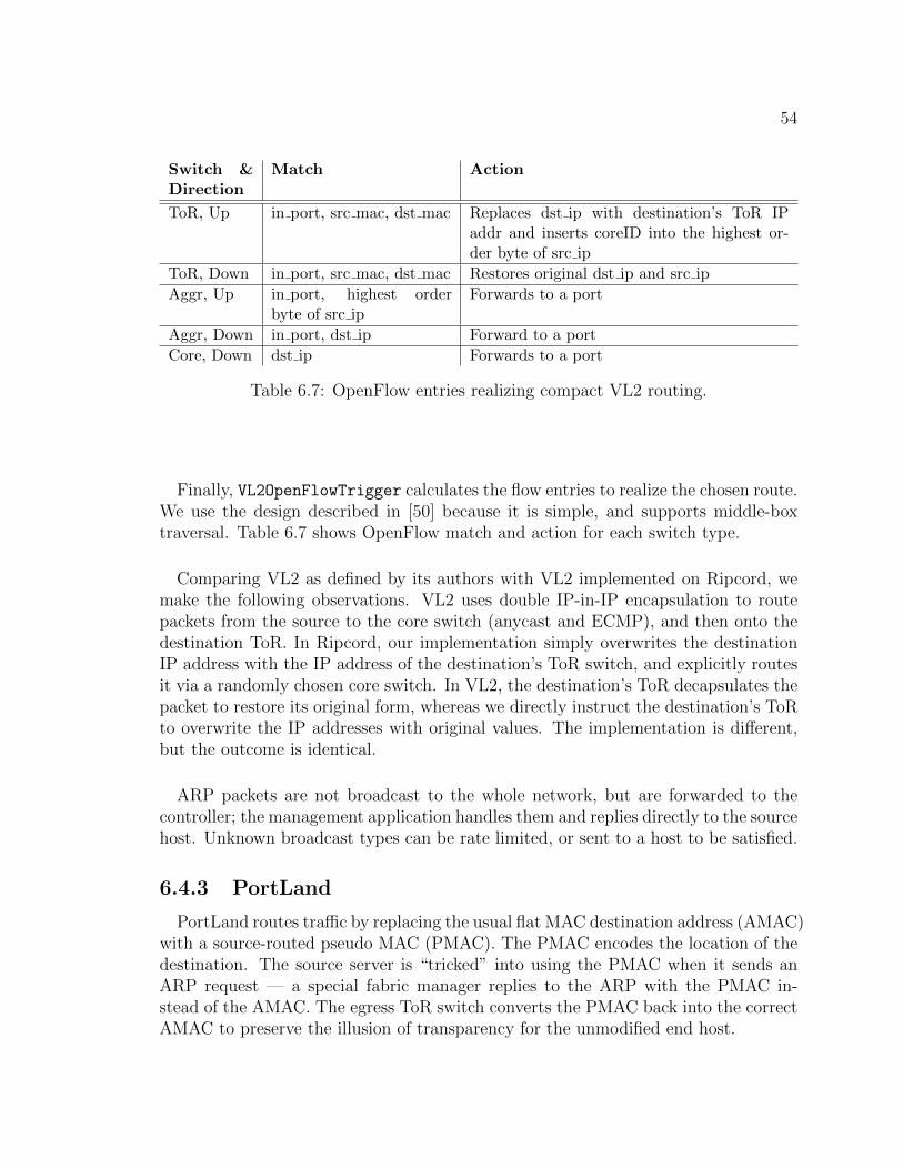
54
Switch &Direction
Match Action
ToR, Up in port, src mac, dst mac Replaces dst ip with destination’s ToR IPaddr and inserts coreID into the highest or-der byte of src ip
ToR, Down in port, src mac, dst mac Restores original dst ip and src ip
Aggr, Up in port, highest orderbyte of src ip
Forwards to a port
Aggr, Down in port, dst ip Forward to a port
Core, Down dst ip Forwards to a port
Table 6.7: OpenFlow entries realizing compact VL2 routing.
Finally, VL2OpenFlowTrigger calculates the flow entries to realize the chosen route.We use the design described in [50] because it is simple, and supports middle-boxtraversal. Table 6.7 shows OpenFlow match and action for each switch type.
Comparing VL2 as defined by its authors with VL2 implemented on Ripcord, wemake the following observations. VL2 uses double IP-in-IP encapsulation to routepackets from the source to the core switch (anycast and ECMP), and then onto thedestination ToR. In Ripcord, our implementation simply overwrites the destinationIP address with the IP address of the destination’s ToR switch, and explicitly routesit via a randomly chosen core switch. In VL2, the destination’s ToR decapsulates thepacket to restore its original form, whereas we directly instruct the destination’s ToRto overwrite the IP addresses with original values. The implementation is different,but the outcome is identical.
ARP packets are not broadcast to the whole network, but are forwarded to thecontroller; the management application handles them and replies directly to the sourcehost. Unknown broadcast types can be rate limited, or sent to a host to be satisfied.
6.4.3 PortLand
PortLand routes traffic by replacing the usual flat MAC destination address (AMAC)with a source-routed pseudo MAC (PMAC). The PMAC encodes the location of thedestination. The source server is “tricked” into using the PMAC when it sends anARP request — a special fabric manager replies to the ARP with the PMAC in-stead of the AMAC. The egress ToR switch converts the PMAC back into the correctAMAC to preserve the illusion of transparency for the unmodified end host.

55
Portland’s fabric manager is centralized, and is naturally implemented as a Ripcordmanagement application. The application assigns each AMAC a PMAC based on itsToR switch. Like in PortLand, ARP requests are intercepted and the managementapplication replies (without routing the ARP request).
PortLand routes flows with a pipeline of three routing modules: PLComputeRoutes,PLPickRoute and PLOpenFlowTrigger. Although the modules are sufficient to imple-ment the PortLand’s routing, we allow it to be extended with other routing modules(e.g., middlebox interposition module or load balancer). Hence, PLComputeRoutes,which belongs to the ComputeRoute stage, first examines loose source routes com-puted by the previous routing stages. If no route is given, it takes a pair of ingressswitch and the ToR switch of destination address as a loose source route. Then,it completes each loose source route by computing a shortest path between eachtwo consecutive hops in the source route. Hence, this routing module results in alist of complete source routes. PLPickRoute is also in the ComputeRoute stage andit randomly selects a route among those computed by PLComputeRoutes. Finally,PLOpenFlowTrigger converts the selected route into a sequence of flow entries to beinstalled in OpenFlow switches along the path.
The ingress ToR replaces the source AMAC with the source PMAC for the returnjourney. Aggregate switches and core switches route solely based on the destina-tion PMAC. Because our OpenFlow implementation does not support longest prefixmatching on MAC addressesx, we currently match full destination address. A flowentry in the egress ToR switch is to restore the destination PMAC back to AMAC.
6.4.4 Additional Capabilities
Because of its fine-grained control over routing, Ripcord can do many things acurrent data center network cannot. We describe some examples below.
Middle-box Traversal
Flows can easily be routed through arbitrary middle-boxes by inserting a waypointin a loose source route (in the InsertWayPoints routing stage). In the ComputeRoutestage, the complete path is calculated to traverse the waypoints. As an experiment,we implemented a routing module VL2MiddleBoxInserter to insert a random middle-box (specified in a configuration file) into the VL2 routing pipeline. Thus, the com-plete VL2 pipeline becomes:

56
VL2MiddleBoxInserter
=⇒VL2LoadBalancer
=⇒VL2ComputeRoute
=⇒VL2OpenFlowTrigger
If the middle box doesn’t modify the packet header, our implementation handlesan arbitrary number of middle-boxes per path. If the packet header is changed, theportion of the route after the middle-box needs to be recomputed. Alternatively,we could define a model for each middle-box class. While out of the scope of thisdissertation, [20] indicates that this approach has potential.
Seamless fail-over
Topology changes are detected by the Topology Database and any managementapplication affected by the change is immediately notified, so it can take remedialactions. This failure detection mechanism is superior in terms of detection latency totime-out-based, classical approaches.
6.5 Evaluation
We evaluate Ripcord against its intended purpose, to evaluate and compare differ-ent approaches in a consistent way. With this goal in mind, we demonstrate threerouting engines (All Pairs Shortest Path [APSP], PortLand, VL2) and an application,Middlebox Traversal. We evaluate each one on a software OpenFlow implementation,and then deploy it on a hardware testbed. We evaluate relative differences betweenimplementations, looking at how flow setup delays and switch state requirements vary.
6.5.1 Software testbed
The software testbed runs inside a Debian Lenny virtual machine, allocated oneCPU core and 256MB of memory, on a machine with Intel Q6600 quad-core 2.4GHzCPU. The testbed spawns kernel-mode software OpenFlow reference switches (avail-able from [33]), running version 0.8.9r2. The controller is NOX 0.6, with Ripcordcore components and applications on top.
6.5.2 Hardware testbed
The hardware testbed implements a k=4 three-layer Fat Tree topology running at1Gbps. Aggregation and core switches are implemented by slicing a 48-port 1GEswitch (Quanta LB4G) running OpenFlow. Eight 4-port NetFPGAs act as edgeswitches. The OpenFlow implementation on the NetFPGAs can rewrite source and
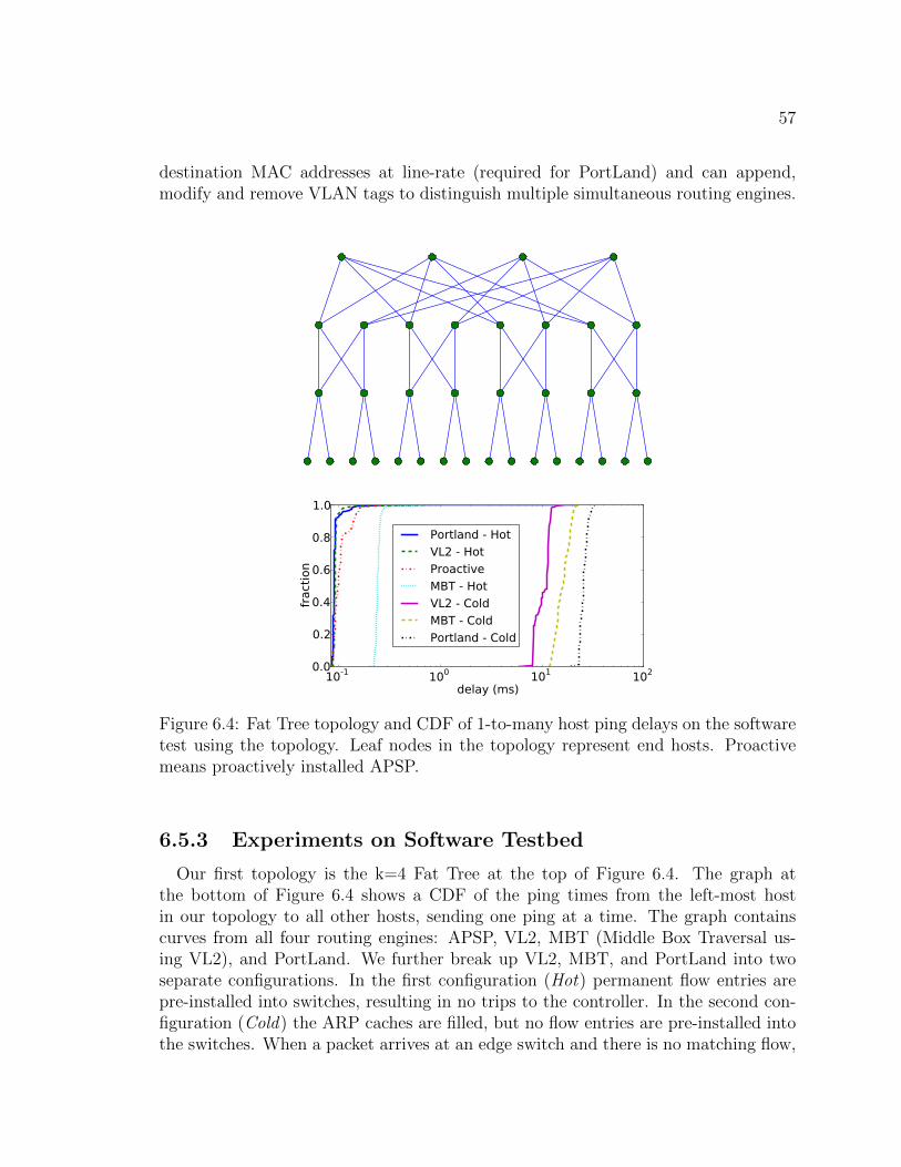
57
destination MAC addresses at line-rate (required for PortLand) and can append,modify and remove VLAN tags to distinguish multiple simultaneous routing engines.
10-1 100 101 102
delay (ms)
0.0
0.2
0.4
0.6
0.8
1.0
fract
ion
Portland - Hot
VL2 - Hot
Proactive
MBT - Hot
VL2 - Cold
MBT - Cold
Portland - Cold
Figure 6.4: Fat Tree topology and CDF of 1-to-many host ping delays on the softwaretest using the topology. Leaf nodes in the topology represent end hosts. Proactivemeans proactively installed APSP.
6.5.3 Experiments on Software Testbed
Our first topology is the k=4 Fat Tree at the top of Figure 6.4. The graph atthe bottom of Figure 6.4 shows a CDF of the ping times from the left-most hostin our topology to all other hosts, sending one ping at a time. The graph containscurves from all four routing engines: APSP, VL2, MBT (Middle Box Traversal us-ing VL2), and PortLand. We further break up VL2, MBT, and PortLand into twoseparate configurations. In the first configuration (Hot) permanent flow entries arepre-installed into switches, resulting in no trips to the controller. In the second con-figuration (Cold) the ARP caches are filled, but no flow entries are pre-installed intothe switches. When a packet arrives at an edge switch and there is no matching flow,

58
it heads for the controller, where its trip through the routing engine pipeline maygenerate flow entries for multiple switches. The APSP routing engine only supportsHot operation. It does no reactive lookups and simply pushes out all possible pathsdirectly to the switches.
10-1 100 101 102 103
delay (ms)
0.0
0.2
0.4
0.6
0.8
1.0
fract
ion PortLand - Hot
VL2 - Hot
MBT - Hot
VL2 - Cold
PortLand - Cold
MBT - Cold
Figure 6.5: Clos topology and CDF of 1-to-many host ping delays on the softwaretestbed using the topology. Leaf nodes in the topology represent end hosts.
APSP experiences slightly higher delay compared to PortLand-Hot and VL2-Hot,due to the higher number of wildcard flow entries in the software switch, which arescanned linearly to determine a match. PortLand-Hot and VL2-Hot both show similarcurves, and since they leverage topology information to reduce flow state, switchtraversal is faster. MBT-Hot is roughly one and a half times worse than regularVL2-Hot because it must traverse a middle box in both directions, and experiencesdelays from our repeater agent running on the middle box. VL2-Cold, MBT-Cold,and PortLand-Cold, as expected, trail by over two orders of magnitude, becauseboth the ping request and response must pass up to the controller and back. Notethat these numbers are from an unoptimized Python implementation, running on a

59
single thread, with a worst case traffic pattern. Thus, the specific ping time of 10ms is unimportant; our goal here is functional correctness and relative comparisonbetween routing schemes. For example, we can see from the graph that our PortLandimplementation is slower than the VL2 implementation in the Cold setting, possiblybecause of its unoptimized memory accesses (i.e. PMAC-AMAC mapping table) andthe latency to install more entries at core switches and aggregation switches.
Our second topology is a Clos network shown at the top of Figure 6.5. This is thetopology used in the VL2 paper’s evaluation, except instead of a mix of 10 Gb/s and1 Gb/s links, we have one link speed of whatever the CPU will support. As withthe result of Fat Tree topology, the bottom graph of Figure 6.5 shows a CDF of pingtimes from the left-most host in the topology. The general trends are the same; flowsetups are two orders of magnitude more expensive than forwarding (due to trip tothe controller). Middlebox traversal has an unexpected knee. We conjecture thatthe additional flow entries required by multiple hops exceeds the CPU cache, whichgiven linear lookups, would cause poor cache locality. These graphs are useful forcomparing the different routing engines, but clearly CPU overheads from running insoftware result in low performance fidelity.
6.5.4 Experiment on Hardware Testbed
The hardware testbed described in Section 6.5.2 implements a k=4 Fat Tree, withtwelve core and aggregation switches and eight NetFPGAs for edge switches. Indi-vidual virtual switches are connected together via physical loopback cables, and allpackets are processed in hardware at line-rate. Both switch types use the OpenFlow0.8.9 reference distribution.
100 101 102
delay (ms)
0.0
0.2
0.4
0.6
0.8
1.0
fract
ion
Proactive
Portland - Hot
Portland - Cold
Figure 6.6: CDF of 1 to many host ping delays on the hardware testbed.

60
Figure 6.6 confirms our expectation of lower variance in hardware than in software— overall we can expect greater performance fidelity. PortLand-Hot and APSP showidentical delay curves, with minimal variation. Next, we attempt to gain insight intotradeoffs between state management and flow setup delay.
6.5.5 Flow Table Size
To test our implementation and to illustrate the consequences of choosing differentflow entry timeout intervals, we preformed the following two tests. First, we runour VL2 Ripcord application on the Clos topology on the software testbed, withpermanent flow entries, and perform an all-to-all ping. After the test, we query allthe switches and record the number of flows entries in each switch. Table 6.8 presentsthe result. The choice of a CRC-based hash function to pick a path, combined witha symmetric test and topology, yields evenly distributed flow entries at each level.The ToR switch has many entries because it keeps per flow state. As discussed insection 6.6, one way to solve this problem is to move the per-flow packet manipulationfunctionality to the hosts. Indeed, [12] performs the IP-in-IP encapsulation at thehost. In the context of OpenFlow, this solution can be best realized by running anOpen vSwitch [35] at the hosts. Ripcord would control it just like any other OpenFlowswitch because of vSwitch’s support for the OpenFlow protocol.
The second experiment is the same as the first one, except that the idle flow timeoutinterval is set to 3 seconds. Every 10 ms, we poll the switches and record the numberof flow entries. Table 6.9 shows the average, maximum, and 95th percentile of thenumber of flow entries in each switch. As the table shows, because only a few entriesare actively used at any given time, expiring the idle ones dramatically reduces thetable size.
Switch Type # Instances # Entries (per instance)
Core 2 4
Aggregation 4 10
ToR 4 2780
Table 6.8: The number of flow entries installed at each switch by VL2 implementationwith no flow idle timeout.
6.5.6 Running Simultaneous Ripcord Applications
To test Ripcord’s ability to run multiple management applications simultaneously,we run several experiments with both VL2 and Portland controlling a subset of traffic.We randomly divided the hosts into two groups and configured the Authenticator-Demultiplexer to classify the traffic within the first group as belonging to VL2 and

61
Switch ID Switch Type Avg #Entries Max 95th percentile
0 Core 3.88 4 4
1 Core 3.86 4 4
2 Aggr 7.61 10 8
3 Aggr 7.50 10 9
4 Aggr 7.73 10 9
5 Aggr 7.75 10 9
6 ToR 142.78 336 74
7 ToR 140.00 292 190
8 ToR 141.40 294 64
9 ToR 143.69 325 154
Table 6.9: The number of flow entries installed at each switch by VL2 implementationwith flow idle timeout of 3 seconds.
the traffic within the second group as belonging to Portland. In each experiment, werun pings between hosts in each group and repeated the experiments on both Closand FatTree topologies.
Figure 6.7 illustrates a simplified scenario and shows the informaton flow. HostsH1 and H3 belong to VL2 and hosts H2 and H4 belong to Portland. H1 is sendingpackets to H3 (path is shown in bold), and H4 is sending packets to H2 (path isshown with a dashed line). When the first packets from these flows hit the first hopToR switches, the switches do not have any matching entry, and hence they forwardthe packets to Ripcord. There Authenticator-Demultiplexer classifies the traffic anddelivers the FLOW IN event to the appropriate application, which eventually installsthe necessary entries in all switches on the path.
As the figure shows, some switches can be common to both paths. These switcheswill contain flow entries for both applications. Hence, it is critical to make surethat applications do not install conflicting entries. In general, this separation canbe achieved by tagging traffic belonging to different applications with diffrent VLANIDs. In our case, because of the specifics of Portland’s and VL2’s implementations,their flow entries could not possibly collide and we did not implement VLAN taggingbecause our hardware testbed did not support this optional functionality.
6.6 Scalability
A primary goal of Ripcord is to provide a research platform for data center net-work architecture experimentation. To this end, a fundamental requirement for theplatform is that it does not hinder experiments with reasonable network sizes or limit
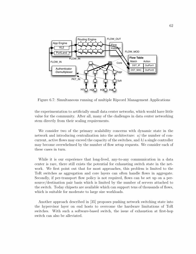
62
H1 H2 H3 H4
Authenticator-Demultiplexer
App EngineVL2
PortLand
ToR
Aggr
Core
Routing Engine
PKT_IN
FLOW_INFLOW_IN
FlowInstaller
Flow Table
DST_IP
DST_MAC
FLOW_OUT
FLOW_MOD
OutPort1
OutPort2
Match Action
Figure 6.7: Simultaneous running of multiple Ripcord Management Applications
the experimentation to artificially small data center networks, which would have littlevalue for the community. After all, many of the challenges in data center networkingstem directly from their scaling requirements.
We consider two of the primary scalability concerns with dynamic state in thenetwork and introducing centralization into the architecture: a) the number of con-current, active flows may exceed the capacity of the switches, and b) a single controllermay become overwhelmed by the number of flow setup requests. We consider each ofthese cases in turn.
While it is our experience that long-lived, any-to-any communication in a datacenter is rare, there still exists the potential for exhausting switch state in the net-work. We first point out that for most approaches, this problem is limited to theToR switches as aggregation and core layers can often handle flows in aggregate.Secondly, if per-transport flow policy is not required, flows can be set up on a per-source/destination pair basis which is limited by the number of servers attached tothe switch. Today chipsets are available which can support tens of thousands of flows,which is suitable for moderate to large size workloads.
Another approach described in [35] proposes pushing network switching state intothe hypervisor layer on end hosts to overcome the hardware limitations of ToRswitches. With such a software-based switch, the issue of exhaustion at first-hopswitch can also be alleviated.
63
Flow setups can become a scalability bottleneck of the platform in terms of flowsetup latencies and throughput. We’ll discuss the scalability of setup latency first.While many of the data center applications like MapReduce tolerate delays on theorder of tens of milliseconds, applications that have strict latency requirements maynot tolerate any extra delay incurred by setting up flow entries. For such demandingapplications, assuming a large enough flow table at the ToR switch either in hard-ware or software, Ripcord can pre-install flow entries towards all possible networkdestinations into the switch. In this proactive mode, therefore, the network virtuallybehaves as if MPLS-tunneled, and applications are not exposed to additional latencyfor flow setup. If the luxury of large flow tables is not available, additional decisionhints such as application priorities or communication pair likelihood can be used toselect pre-loaded flows. In our current prototype, such information could be storedin the Configuration/Policy database module and/or topology database module.
Scaling flow setup throughput beyond the limits of a single controller requires thatthe platform support multiple controller instances. However, before diving into thedetails, it is worthwhile to explicitly differentiate between the scalability requirementsresearch and production quality platforms for data center networks.
The goal of Ripcord, at least in its current incarnation, is not to provide a researcherwith a production quality implementation. The implementation lacks in many as-pects, such as in efficiency, robustness, and importantly Ripcord is built around asimple, centralized, single-host state sharing mechanism. If subjected to the extremescalability and availability requirements of data center networks in production, thismechanism is clearly insufficient.
In research experiments the lack of extreme scalability and availability propertiesis a non-issue as long as the programming abstractions offered for the applicationdevelopers are similar to the ones, which would be provided in systems designed toscale for production use. To this end, we briefly overview the scalability approachesof both Portland and VL2:
• Portland centralizes all state sharing into a fabric manager component, whichmanages the switch modules over OpenFlow. As such, the fabric managercorresponds directly with a single Ripcord controller instance.
• VL2 assumes no single, centralized controller instance, but uses a distributeddirectory system to share state among multiple controllers (agents). The direc-tory system is essentially a strongly-consistent, reliable and centralized store,which has an eventually consistent caching layer for reads on top.

64
The descriptions above suggest that the design of Ripcord is well aligned withthe scalability approaches of these individual proposals. In particular, Ripcord canprovide the platform for centralized single-controller designs like PortLand, while forVL2 like designs, which rely on a distributed state sharing mechanism, Ripcord canprovide a single-host configuration database with the identical semantics. This isclearly not scalable (nor highly-available), but the programming abstractions withinthe controllers connected to the database will be the same as if a distributed statesharing mechanism were used. Eventually, as Ripcord matures, it could also replacethis centralized, single-host configuration database with a distributed database.
6.7 Related Work
Ripcord is built on top of programmable switches and a logically centralized con-trol platform. In our prototype we use OpenFlow [28] switches and NOX [16], anopen-source OpenFlow controller. OpenFlow is a vendor-agnostic interface to con-trol network switches and routers. In particular, it provides an abstraction of theflow-tables already present in most devices - they were originally placed there to holdfirewall rules. OpenFlow allows rules to be placed in a table, consisting of a <headerpattern, action> pair. If an arriving packet matches the header pattern, the as-sociated action is performed. Actions are generally simple, such as forward to a portor set of ports, drop, or send to the controller. Our use of OpenFlow was a matterof familiarity and convenience. However, other than the table and port abstractions,no low-level details of OpenFlow are exposed through Ripcord. Therefore, the Rip-cord design should be compatible with other programmable switch technologies thatmaintain table-entry level control of the network.
NOX is a network-wide operating system that controls a collection of switches androuters using the OpenFlow protocol. NOX provides a global view of the topology,and presents an API to hosted applications to both view and control the network state.A hosted application might reactively respond to new flows, choose whether to allowthem and then install rules to determine their path. Otherwise, it could proactivelyadd rules to define how new flows will be routed. While NOX was designed to be ageneral controller platform applicable to many environments, Ripcord was designedaround needs specific to the datacenter. This includes providing infrastructure formanaging structured topology, location independence, and service quality as well asexposing higher-level abstractions, such as tenants. We chose NOX in large part dueto our familiarity with it, Ripcord could also have been implemented within othercentralized network control platforms such as Tesseract [13] or Maestro [6]. LikeNOX, both of these projects provide centralized development platforms on top ofwhich network control logics can be implemented.

65
Having described related technologies for programmable switches and controllers wenow discuss Ripcord in the context of recent data center networking proposals (e.g.,VL2 [12], Monsoon [14], BCube [17], PLayer [20], and PortLand [32]). We note thateach of these networking proposals presents a solution based on specific requirements,some of which overlap across solutions, but may be prioritized differently in eachsolution. As a consequence specific architectural choices are made that may make itdifficult to accommodate new requirements, changes to data center environments ormodifications to the solution that attempt to tailor/tweak it for another data centerenvironment.
Ripcord is not in direct competition with any of these networking proposals, ratherit provides a platform that allows network administrators to experiment with one ormore of data center networking proposals (side-by-side if necessary), make modifi-cations and evaluate the proposal in their own data center environments. Further,whereas Ripcord does not include or propose any novel distributed algorithms formanaging data center networks, we posit that it provides a suitable platform forexperimentation in this space based on its modular design.
Ripcord is also similar in spirit to the broad testbased work which allows mult-ple experiments to share the same infrastructure. Notable recent proposals includeVINI [5], and FlowVisor [45]. Ripcord differs from these and similar proposals inthat our goal is to construct a modular platform at the control level which providesprimitives useful in the data center context. To this end, we have designed multiplecomponents (such as the topology and monitoring interfaces) which aid (and limit!)the applications suitable for running on Ripcord.

66
Chapter 7
Conclusion
7.1 Contribution Summary
This dissertation consists of two main contribution to achieve both high flexibilityand low cost/performance in packet forwarding and data center networking.
We have proposed SDF as a hybrid approach to building packet forwarding de-vices. The SDF approach we have presented here contains nothing new; it merelyglues together two well-known components (software decisions and hardware classifi-cation) into a complete forwarding solution. We have designed a high-level API thatallows forwarding solutions to be developed in a high-level language independent ofthe low-level hardware implementation. The approach can be implemented on top ofOpenFlow or other similar hardware interfaces, or could be ported directly to com-mercial switch SDKs. Our preliminary work suggests that this combination of knowncomponents provides a flexible packet forwarding platform that, because it is basedon standard hardware (e.g., TCAMs), should offer competitive cost/performance.
Next we have presented Ripcord as a general platform for data center networkingand management. Instead of exposing a low-level interface, Ripcord provides a well-defined, high-level interface across underlying networks. Ripcord is designed logicallycentralized, multi-tenant friendly, and modular so as to have a complete networkview and to facilitate algorithms comparison and rapid prototyping. The platformcan be implemented on top of programmable switch technologies (e.g., OpenFlowlike our prototype) and centralized network controllers such as NOX. Our preliminaryexperience with Ripcord suggests that Ripcord can be a good platform for data centernetwork architecture experiments.

67
7.2 Future Directions
More study on cache performance of SDF. Although our preliminary ex-periments have shown promising results about cache locality and random denial-of-service attacks, we do not claim to have solved all performance problems associatedwith caching in SDF. While the proactive mode is clearly safer, the reactive modemay still be an attractive choice considering how small the state requirements are toachieve low miss rates. Thus, it would be interesting to evaluate more packet tracesand routing algorithms to figure out what operating environments well fit or does notfit to SDF.
Forwarding flexibility in production networks? We think that SDF may provequite useful in building experimental networks. Especially, network architecture re-searches could find a great value from SDF. However, its relevance to productionnetworks is more questionable, as the need for flexibility in that context remains anopen question.
Study on scalability of Ripcord. It is still an open question to what extentthe platform should scale to provide value to different communities. The researchcommunity, which principally targets devising, rapidly developing, and evaluatingnew ideas, could be an immediate beneficiary, even with networks on smaller scales.For those networks, even our current Ripcord prototype can be an ideal vehicle sinceit is capable of emulating a 100-node data center on a modern laptop computer andit supports seamless porting from software emulation to real hardware testbeds. Fora designer of a production data center seeking radically new approaches to improvenetworking performance, or trying to introduce competitive features, Ripcord mayalso prove valuable, as long as the size of the testbed is not on the order of theproduction network.

68
Bibliography
[1] Mohammad Al-Fares, Alexander Loukissas, and Amin Vahdat. A scalable, com-modity data center network architecture. In SIGCOMM ’08: Proceedings of theACM SIGCOMM 2008 conference on Data communication, pages 63–74, NewYork, NY, USA, 2008. ACM. pages 7
[2] Thomas Anderson, Larry Peterson, Scott Shenker, and Jonathan Turner. Over-coming the internet impasse through virtualization. Computer, 38(4):34–41,2005. pages 27
[3] Katerina J. Argyraki, Salman Baset, Byung-Gon Chun, Kevin R. Fall, GianlucaIannaccone, Allan Knies, Eddie Kohler, Maziar Manesh, Sergiu Nedevschi, andSylvia Ratnasamy. Can Software Routers Scale? In Proc. of PRESTO, 2008.pages 22
[4] Arista Networks. http://www.aristanetworks.com. pages 35
[5] Andy Bavier, Nick Feamster, Mark Huang, Larry Peterson, and Jennifer Rexford.In VINI Veritas: Realistic and Controlled Network Experimentation. In Proc. ofSIGCOMM, Pisa, Italy, 2006. pages 27, 65
[6] Zheng Cai, Florin Dinu, Jie Zheng, Alan L. Cox, and T. S. Eugene Ng. ThePreliminary Design and Implementation of the Maestro Network Control Plat-form. Technical Report TR08-13, Rice University, 2008. Available athttp://www.cs.rice.edu/~eugeneng/papers/Maestro-TR.pdf. pages 64
[7] Cavium Networks. http://www.caviumnetworks.com/. pages 34
[8] Cisco. Data Center Ethernet. http://www.cisco.com/go/dce. pages 7
[9] ControlPoint Developers Alliance. http://www.fulcrummicro.com/cda/. pages5
[10] Mihai Dobrescu, Norbert Egi, Katerina Argyraki, Byung-Gon Chun, KevinFall, Gianluca Iannaccone, Allan Knies, Maziar Manesh, and Sylvia Ratnasamy.

69
Routebricks: exploiting parallelism to scale software routers. In SOSP ’09: Pro-ceedings of the ACM SIGOPS 22nd symposium on Operating systems principles,pages 15–28, New York, NY, USA, 2009. ACM. pages 6
[11] Norbert Egi, Adam Greenhalgh, Mark Handley, Mickael Hoerdt, Felipe Huici,and Laurent Mathy. Towards High Performance Virtual Routers on CommodityHardware. In Proc. of CoNEXT, 2008. pages 22, 34
[12] Albert Greenberg, James R. Hamilton, Navendu Jain, Srikanth Kandula,Changhoon Kim, Parantap Lahiri, David A. Maltz, Parveen Patel, and SudiptaSengupta. VL2: A Scalable and Flexible Data Center Network. In Proc. ofSIGCOMM, Barcelona, Spain, 2009. pages 2, 3, 4, 7, 28, 41, 42, 60, 65
[13] Albert Greenberg, Gisli Hjalmtysson, David A. Maltz, Andy Myers, JenniferRexford, Geoffrey Xie, Hong Yan, Jibin Zhan, and Hui Zhang. A Clean Slate4D Approach to Network Control and Management. ACM SIGCOMM CCR,35(5):41–54, 2005. pages 64
[14] Albert Greenberg, Parantap Lahiri, David A. Maltz, Parveen Patel, and SudiptaSengupta. Towards a next generation data center architecture: scalability andcommoditization. In PRESTO ’08: Proceedings of the ACM workshop on Pro-grammable routers for extensible services of tomorrow, pages 57–62, New York,NY, USA, 2008. ACM. pages 2, 4, 7, 65
[15] Natasha Gude, Teemu Koponen, Justin Pettit, Ben Pfaff, Martın Casado, NickMcKeown, and Scott Shenker. Nox: towards an operating system for networks.SIGCOMM Comput. Commun. Rev., 38(3):105–110, 2008. pages 14
[16] Natasha Gude, Teemu Koponen, Justin Pettit, Ben Pfaff, Martın Casado, NickMcKeown, and Scott Shenker. Nox: towards an operating system for networks.SIGCOMM Comput. Commun. Rev., 38(3):105–110, 2008. pages 43, 64
[17] Chuanxiong Guo, Guohan Lu, Dan Li, Haitao Wu, Xuan Zhang, Yunfeng Shi,Chen Tian, Yongguang Zhang, and Songwu Lu. Bcube: a high performance,server-centric network architecture for modular data centers. In SIGCOMM,pages 63–74, 2009. pages 2, 4, 65
[18] Mark Handley, Eddie Kohler, Atanu Ghosh, Orion Hodson, and Pavlin Ra-doslavov. Designing Extensible IP Router Software. In Proc. of NSDI, 2005.pages 26
[19] Integrated Device Technology (IDT). http://www.idt.com/. pages 21
[20] Dilip A. Joseph, Arsalan Tavakoli, and Ion Stoica. A policy-aware switchinglayer for data centers. SIGCOMM Comput. Commun. Rev., 38(4):51–62, 2008.pages 2, 4, 56, 65

70
[21] James Kelly, Wladimir Araujo, and Kallol Banerjee. Rapid Service Creationusing the JUNOS SDK. In Proc. of PRESTO, 2009. pages 5
[22] Changhoon Kim, Matthew Caesar, Alexandre Gerber, and Jennifer Rexford.Revisiting Route Caching: The World Should Be Flat. In Proc. of PAM, 2009.pages 14
[23] Changhoon Kim, Matthew Caesar, and Jennifer Rexford. Floodless in Seattle:A Scalable Ethernet Architecture for Large Enterprises. In Proc. of SIGCOMM,2008. pages 29, 32
[24] Murali Kodialam, T. V. Lakshman, and Sudipta Sengupta. Efficient and robustrouting of highly variable traffic. In In Proceedings of Third Workshop on HotTopics in Networks (HotNets-III, 2004. pages 7
[25] LBNL/ICSI Enterprise Tracing Project. http://www.icir.org/
enterprise-tracing. pages 35
[26] Linux-VServer, 2009. http://www.linux-vserver.org/. pages 28
[27] Guohan Lu, Yunfeng Shi, Chuanxiong Guo, and Yongguang Zhang. CAFE: AConfigurable pAcket Forwarding Engine for Data Center Networks. In Proc. ofPRESTO, pages 25–30, 2009. pages 6
[28] Nick McKeown, Tom Anderson, Hari Balakrishnan, Guru Parulkar, Larry Pe-terson, Jennifer Rexford, Scott Shenker, and Jonathan Turner. OpenFlow: En-abling Innovation in Campus Networks. ACM SIGCOMM CCR, 38(2):69–74,2008. pages 14, 43, 64
[29] Jeffrey C. Mogul, Praveen Yalagandula, Jean Tourrilhes, Rick McGeer, SujataBanerjee, Tim Connors, and Puneet Sharma. Orphal: API Design Challengesfor Open Router Platforms on Proprietary Hardware. In Proc. of HotNets, 2008.pages 5, 14
[30] Jad Naous, Glen Gibb, Sara Bolouki, and Nick McKeown. NetFPGA: ReusableRouter Architecture for Experimental Research. In Proc. of PRESTO, 2008.pages 22
[31] Netlogic Microsystems. http://www.netlogicmicro.com/. pages 21
[32] Radhika Niranjan Mysore, Andreas Pamboris, Nathan Farrington, NelsonHuang, Pardis Miri, Sivasankar Radhakrishnan, Vikram Subramanya, and AminVahdat. Portland: a scalable fault-tolerant layer 2 data center network fabric. InSIGCOMM ’09: Proceedings of the ACM SIGCOMM 2009 conference on Datacommunication, pages 39–50, New York, NY, USA, 2009. ACM. pages 2, 3, 4,7, 41, 42, 65

71
[33] OpenFlow Switch Consortium. http://www.openflowswitch.org. pages 56
[34] Larry Peterson, Andy Bavier, Marc E. Fiuczynski, and Steve Muir. ExperiencesBuilding PlanetLab. In Proc. of OSDI, pages 351–366, 2006. pages 28
[35] Ben Pfaff, Justin Pettit, Teemu Koponen, Keith Amidon, Martin Casado, andScott Shenker. Extending Networking into the Virtualization Layer. In 8th ACMWorkshop on Hot Topics in Networking (Hotnets), New York City, NY, October2009. pages 60, 62
[36] Quagga Routing Suite. http://www.quagga.net. pages 26
[37] Jennifer Rexford, Jia Wang, Zhen Xiao, and Yin Zhang. BGP Routing Stabilityof Popular Destinations. In Proc. of IMW, pages 197–202, 2002. pages 35
[38] University of Oregon Route Views Project. http://www.routeviews.org. pages30
[39] Gregor Schaffrath, Christoph Werle, Panagiotis Papadimitriou, Anja Feldmann,Roland Bless, Adam Greenhalgh, Andreas Wundsam, Mario Kind, Olaf Maennel,and Laurent Mathy. Network Virtualization Architecture: Proposal and InitialPrototype. In Proc. of VISA, pages 63–72, Barcelona, Spain, 2009. pages 27
[40] Devavrat Shah and Pankaj Gupta. Fast Incremental Updates on Ternary-CAMsfor Routing Lookups and Packet Classification. In Proc. of HotI, 2000. pages 32
[41] Colleen Shannon, Emile Aben, kc claffy, and Dan Andersen. The CAIDAAnonymized 2007 Internet Traces - Jan 2007. http://www.caida.org/data/
passive/passive_2007_dataset.xml. pages 35
[42] Colleen Shannon, Emile Aben, kc claffy, and Dan Andersen. The CAIDAAnonymized 2008 Internet Traces - May 2008. http://www.caida.org/data/
passive/passive_2008_dataset.xml. pages 35
[43] Colleen Shannon, Emile Aben, kc claffy, and Dan Andersen. The CAIDAAnonymized 2009 Internet Traces - Feb, Mar 2009. http:// www.caida.org/
data/passive/passive_2009_dataset.xml. pages 35
[44] Colleen Shannon, Emile Aben, kc claffy, Dan Andersen, and Nevil Brownlee.The CAIDA OC48 Traces Dataset - Aug 2002. http://www.caida.org/data/
passive/passive_oc48_dataset.xml. pages 35
[45] Rob Sherwood, Michael Chan, Glen Gibb, Nikhil Handigol, , Te-Yuan Huang,Peyman Kazemian, Masayoshi Kobayashi, David Underhill, Kok-Kiong Yap,Guido Appenzeller, and Nick McKeown. Carving Research Slices Out of YourProduction Networks with OpenFlow, 2009. pages 52, 65

72
[46] Haoyu Song and Jonathan S. Turner. Fast Filter Updates in TCAMs for PacketClassification. In Proc. of GLOBECOM, pages 147–160, 2006. pages 32
[47] Ed Spitznagel, David E. Taylor, and Jonathan S. Turner. Packet ClassificationUsing Extended TCAMs. In Proc. of ICNP, pages 120–131, November 2003.pages 21
[48] Ion Stoica, Daniel Adkins, Shelley Zhuang, Scott Shenker, and Sonesh Surana.Internet Indirection Infrastructure. In Proc. of SIGCOMM, 2002. pages 28, 33
[49] Ion Stoica, Robert Morris, David Karger, M. Frans Kaashoek, and Hari Balakr-ishnan. Chord: A Scalable Peer-to-peer Lookup Service for Internet Applications.In Proc. of SIGCOMM, pages 149–160, 2001. pages 28, 33
[50] Arsalan Tavakoli, Martin Casado, Teemu Koponen, and Scott Shenker. ApplyingNOX to the Datacenter. In 8th ACM Workshop on Hot Topics in Networking(Hotnets), New York City, NY, October 2009. pages 54
[51] J. Touch and R. Perlman. Transparent Interconnection of Lots of Links (TRILL):Problem and Applicability Statement. RFC 5556 (Informational), May 2009.pages 7
[52] Fang Yu, Randy H. Katz, and T. V. Lakshman. Efficient Multimatch PacketClassification and Lookup with TCAM. In Proc. of HotI, 2004. pages 21
[53] Rui Zhang-Shen. Designing a predictable backbone network using valiant load-balancing. PhD thesis, Stanford, CA, USA, 2007. Adviser-Mckeown, Nick. pages7