acknowledgements mission statement asphalt qms …€¦ · their permission to use quotations,...
TRANSCRIPT

Table of Contents Asphalt QMS - 2019
i
PREFACE
This manual has been prepared as a practical guide for asphalt technicians in the construction and inspection of
asphalt pavements. It is intended to serve as a basic introduction to asphalt construction for the new technician as well as
a reference source to those with considerable experience. While it is fully recognized that this manual alone cannot make
a person a totally competent asphalt technician, it should provide the basic knowledge and direction for one truly interested
in becoming qualified, to do so.
The terms “technician”, “inspector”, and “contractor” are used throughout the manual. Generally, when reference
is made to the technician, both the Contractor's representative and the agency's (NCDOT) representative are implied.
Where reference is made to the “inspector” or the “contractor”, then either the agency's (NCDOT) or the contractor's
representative, respectively, are specifically implied. The term “Department Personnel” is utilized throughout this manual.
Historically, all construction inspection has been performed by NCDOT technicians; however, due to increasing work load
and a decreasing number of construction technicians, the Department is utilizing private engineering firms to perform a
portion of the construction inspection. Therefore, when reference is made to “Department Personnel”, this refers to either
an individual working for the NCDOT or an appointed representative of the Department.
The requirements stated herein may be revised or amended from time to time by Supplemental Specifications, by
Standard Special Provisions which are unique to a select group of projects, or by Project Special Provisions which are unique
to the specific bid proposal or contract.
In this manual only masculine pronouns are used in reference to technicians, inspectors and contractors. This
convention is used for the sake of brevity and is intended to refer to persons of either sex or corporate entities.
ACKNOWLEDGEMENTS
The North Carolina Department of Transportation would like to express appreciation to the Asphalt Institute for
their permission to use quotations, graphs, illustrations and other literature in the preparation of this manual.
Appreciation is also expressed to Astec, Blaw-Knox, CMI, Caterpillar, Compaction America, Dynapac, Gencor,
Ingersoll-Rand, Roadtec, Wirtgen, and other equipment manufacturers for the use of their illustrations and information.
Use of specific trade names or manufacturers' illustrations does not imply endorsement by the Department. These are used
solely because they are considered necessary in meeting the objective of this manual.
The Department also expresses appreciation to the Carolina Asphalt Pavement Association, the Federal Highway
Administration, the Transportation Research Board, and others for the use of their materials in the preparation of this
manual.
MISSION STATEMENT
Asphalt QMS Program
The Mission of the Asphalt QMS Program is to continuously improve the overall quality of Asphalt
Pavements in a cost-effective manner through Quality Control and Quality Assurance Processes.
NCDOT MATERIALS AND TESTS UNIT WEBSITE
https://connect.ncdot.gov/resources/Materials/Pages/default.aspx

Asphalt QMS - 2019 Table of Contents
ii
MAJOR CHANGES FOR QMS MANUAL
Section 1: Quality Management System (QMS) for Asphalt Pavements
Page No. Subsection Change
1-4 1.3.6 Updated information on management of QMS Certification programs and website.
1-7 1.3.8 Updated requirements for technician class enrollment. (Online registration required)
1-9 1.4.4 Clarified how a sample can be directed for use in a technician assessment.
Section 2: Materials Used In Asphalt Paving
Page No. Subsection Change
2-2 2.4.3 Removed references to Cutback Asphalts.
Section 3: Asphalt Pavement Design
Page No. Subsection Change
3-3 3.3 Updated Pavement Layer Depth table to match Roadway Design Manual format.
3-3 3.3 Updated Minimum Lift Thickness for S4.75A mixes.
3-3 3.4 Removed Single Layer Thickness/Rate Column to remove confusion.
Various Various Removed all use of Metric measurements.
Section 4: Asphalt Mix Design and Job Mix Formulas
Page No. Subsection Change
4-7 4.5 Added requirement for Binder Producer COA to be included with Mix Design submittals
as a check of binder specific gravity and temperatures.
4-11 4.8 Added reference to AASHTO M 332 test that is used with PG Binder testing.
Section 5: Asphalt Plant Equipment
Page No. Subsection Change
5-7 5.7 Edited requirements for Anti-Strip Additives.
5-7 5.8 Restructured section and added four distinct subsections.
5-8 5.8.3 Added allowance for Batch-Metering system at the Asphalt Mix plant.
Section 6: Asphalt Plant Operations
Page No. Subsection Change
6-4 6.4 Removed paragraph discussing JMF change requests – these are covered in Section 7.4.
6-10 6.5.8 (D) Updated Anti-Strip system calibration requirements to match new allowances.
Section 7: Asphalt Mixture Sampling and Testing
Page No. Subsection Change
7-2 7.2 Allowance for option of Fax Machine OR Scanner for submittal of QMS Forms.
7-13 Table 7-1 Removed Row and Column numbers to encourage proper use of Random No. tables.
7-16 7.4.2 Added word “calendar” to match time requirement in Section 609 of the Specifications.
7-49 7.16.1 Clarified frequency requirements for Verification TSR tests.
7-52 7.16.5 Inserted requirement for leaving vacuum-saturated specimens submerged in water for a
short time to meet requirements of AASHTO and make saturation more consistent.
7-58 7.18.8 Changed wording to “shall” so as to ensure better compliance with QC data entry to QAP
within 24 hours.
7-61 Table 609-3 Added Limits of Precision for S4.75A mixes on the 1.18mm Control Sieve.

Table of Contents Asphalt QMS - 2019
iii
MAJOR CHANGES FOR QMS MANUAL
Section 8: Recycling of Asphalt Pavements
Page No. Subsection Change
8-3 8.3 Added correct Table 610-5 to match 2018 Specifications.
Section 9: Roadway Paving Operations
Page No. Subsection Change
9-3 9.2.1 Added Approved Products website link for finding Approved Prime Coat materials.
9-5 9.3 Added Note to emphasize the importance of allowing Tack to break BEFORE paving.
9-6 9.3.1 Added Approved Products website link for finding Non-Tracking Tack Coat materials.
9-10 9.4.3 Updated second paragraph to match Article 610-4 of 2018 Specifications.
9-11 9.5.1 (C) Added Approved Products website link for finding Truck Release Agents.
9-11 9.5.1 (C) Added qualifier: “If the asphalt plant uses platform scales…” for establishing tare weights.
9-15 9.5.1 Changed “at least four” to “a minimum of three” for required referencing stations.
9-21, 9-22 9.6.3 Changed “at least four” to “a minimum of three” for required referencing stations.
Section 10: Roadway Inspection and Testing of Asphalt Pavements
Page No. Subsection Change
10-3 10.1.3 Added emphasis that Gross/Tare Weights are required if Platform Scales are used.
10-15 10.3.5 Added emphasis that DOT Representative should complete Form QA-5.
10-51 10.7 Added clarification on required DOT density sampling frequency.
Section 11: Pavement Smoothness / Rideability
No Major Changes
Section 12: Records and Reports
Page No. Subsection Change
Various Various Removed references to faxing of forms.

Asphalt QMS - 2019 Table of Contents
iv
TABLE OF CONTENTS
SECTION 1: QUALITY MANAGEMENT SYSTEM (QMS) FOR ASPHALT PAVEMENTS PAGE NO.
General 1-1
Contractor’s Quality Control Plan 1-1
Asphalt QMS Technician Qualifications and Certifications 1-1
Purpose of Inspection and Testing 1-2
DOT Technician’s Authority 1-2
DOT Technician’s Relationship with Contractor 1-2
Qualifications of QC and QA Technicians 1-3
QMS Technician Requirements 1-4
NCDOT Asphalt Technician Certification Program 1-4
NCDOT Asphalt Technician Certification - Enrollment Procedures 1-7
QMS Laboratory Technician Assessment Program 1-9
Ethics and Falsification 1-11
FHWA Form 10-22 1-13
SECTION 2: MATERIALS USED IN ASPHALT PAVING
General Description of Asphalt Paving Materials / Pavements 2-1
Technician Responsibilities 2-1
Asphalt Materials 2-1
Asphalt Binder 2-1
Refining Crude Petroleum 2-2
Classification and Grading of Paving Grade Asphalts 2-2
Asphalt Binders 2-3
Emulsified Asphalts 2-3
Characteristics of Asphalt 2-3
Testing the Properties of Performance Graded Asphalt Binders 2-4
Asphalt Additives 2-5
Asphalt Binder Storage 2-5
Delivery and Acceptance of Asphalt Materials 2-5
NCDOT Specifications for Asphalts (Figure 2-3) 2-7
Emulsified Asphalts (Figure 2-4) 2-7
Temperature-Volume Relationships of Asphalts 2-7
Mineral Aggregates 2-8
Sources of Aggregates 2-8
Evaluating the Quality of Aggregates 2-9
Aggregate Consensus Properties (Table 1012-1) 2-9
Aggregate Gradation Table 1005-1 (Coarse Aggregate) 2-11
SECTION 3: ASPHALT PAVEMENT DESIGN
Designing an Asphalt Pavement Structure (Thickness) 3-1
Asphalt Mix Types 3-2
Pavement Layer Depth Guidelines (For Pavement Design Purposes) 3-3
Application Rates of Spread per Inch Depth 3-3
Typical Asphalt Binder Contents 3-4
Example Roadway Typical Section 3-4
SECTION 4: ASPHALT MIX DESIGN AND JOB MIX FORMULAS
Purposes of Mix Designs 4-1
Performance Characteristics Considered in Mix Design 4-1
Permanent Deformation (Rut Resistance) 4-1
Durability 4-2
Flexibility 4-2
Fatigue (Cracking) Resistance 4-2

Table of Contents Asphalt QMS - 2019
v
SECTION 4: ASPHALT MIX DESIGN AND JOB MIX FORMULAS (cont.) PAGE NO.
Skid Resistance 4-3
Impermeability 4-3
Low Temperature/Shrinkage Cracking 4-3
Workability 4-3
Economics 4-3
The Mix Design Process 4-3
Aggregate Properties and Gradation Requirements 4-3
Asphalt Binder Grade Selection and Requirements 4-4
Mixture Volumetric Properties and Requirements 4-4
Dust to Effective Binder Ratio 4-5
Moisture Susceptibility 4-5
Permanent Deformation (Rut Resistance) 4-5
NCDOT Mix Design Procedures 4-6
The Job Mix Formula 4-8
Aggregate Gradation Criteria (Table 610-2) 4-8
Mix Design Criteria (Table 610-3) 4-9
Maximum Recycled Binder Replacement Percentage (RBR%) (Table 610-4) 4-9
Binder Grade Requirements (Based On RBR%) (Table 610-5) 4-9
NCDOT “Master” Job Mix Formula Procedures 4-10
Composition of Recycled Mixtures (JMF) 4-10
Project File Job Mix Formula Procedures 4-11
Mix Type Designations 4-12
Job Mix Formula Numbering System 4-12
Job Mix Formula Example 4-13
Asphalt Mix Design and Testing Calculations / Formulas 4-14
SECTION 5: ASPHALT PLANT EQUIPMENT AND REQUIREMENTS
Basic Operation of an Asphalt Plant 5-1
Types of Asphalt Plants 5-1
Certification of Asphalt Plants 5-1
Asphalt Plant Specification Checklist 5-3
Batch Plant Operations and Components 5-5
Drum-Mix Plant Operations and Components 5-6
Introduction of Anti-Strip Additive at Batch Plants or Drum Plants 5-7
Introduction of Anti-Strip Additive at Binder Supplier’s Terminal 5-7
Warm Mix Asphalt (WMA) Technologies 5-8
NC Dept. of Agriculture & Consumer Services (NCDA & CS) Scales Certification 5-8
SECTION 6: ASPHALT PLANT OPERATIONS
Asphalt Binder Storage and Handling 6-1
Asphalt Mix Temperature Requirements 6-1
Aggregate Storage 6-2
Aggregate Cold Feed System 6-2
Calibration of Cold Feed Blend Ratios 6-4
Table 6-1: Plant Calibration Frequencies 6-6
Batch Plant Operations 6-6
The Dryer 6-6
Screening Unit 6-7
Hot Bins 6-7
Aggregate Weigh Hopper 6-8
Asphalt Binder Bucket or Meter 6-8
The Mixer Unit (Pugmill) 6-8
Automatic Control of Proportioning and Mixing 6-9
Calibration of Batch Plant Asphalt Scales, Weigh Bridges and Meters 6-9
Setting of Batch Weights 6-11

Asphalt QMS - 2019 Table of Contents
vi
SECTION 6: ASPHALT PLANT OPERATIONS (cont.) PAGE NO.
Drum Mix Plant Operations 6-16
Cold Feed System 6-16
Vibratory Scalping Screen 6-17
Weight Measurement of Aggregate and RAP / RAS 6-17
Asphalt Binder Meter System 6-18
Anti-Strip Additive Meter System 6-20
Drum-Mixer Dryer 6-20
Surge Storage Bins (Silos) 6-20
Segregation of Asphalt Mixtures 6-21
Scales and Public Weighmaster 6-22
Hauling of Asphalt Mixtures 6-22
Pollution Control Equipment 6-23
Safety Requirements 6-23
Production Consistency and Automatic Equipment 6-23
SECTION 7: ASPHALT MIXTURE SAMPLING AND TESTING
Introduction 7-1
QMS Certified Field Laboratory 7-2
QMS Lab Required Equipment List for Asphalt Mix Testing 7-2
QMS Lab Equipment Calibration Requirements 7-4
QMS Plant Sampling Schedule 7-9
Quality Control (QC) Minimum Sampling and Testing Schedule 7-10
Sample Location for Mix 7-11
Sample Location for Aggregates, RAP, & RAS 7-12
NCDOT Random Numbers Table to be used for the QC-9 Form 7-13
Mix Verification, JMF Adjustments, and Corrective Action Procedures 7-16
Mix Verification Requirements 7-16
Allowable Mix Adjustments 7-17
Control Charts (QA/QC-6 Form) 7-18
Table 609-1: Control Limits 7-19
Corrective Actions 7-19
Sampling Procedures 7-22
Aggregate, RAP, and RAS Sampling 7-22
Numbering of Mix Samples 7-22
Sampling Mix from the Truck 7-23
Sampling Device 7-23
Sample Location in Truck 7-23
Obtaining Mix Samples (Full & Partial Test Series) 7-24
QC Quartering (Mix Sample for Full and Partial Test Series) 7-24
QC Quartering (RAP or RAS Samples) 7-25
QA Quartering (Mix Sample for Full and Partial Test Series) 7-25
QA Quartering (Aggregates, RAP, and RAS) 7-26
Test Procedures – General 7-26
Sieve Analysis of Fine and Coarse Aggregates 7-27
Moisture Content of Aggregate by Drying 7-30
Sieve Analysis of Recovered Aggregate 7-31
Asphalt Binder Content of Asphalt Mix by the Ignition Method 7-33
Gyratory Compactor Field Test Procedure 7-37
Maximum Specific Gravity (Gmm) of Asphalt Mix – Rice Method 7-40
Maximum Specific Gravity (Gmm) of Asphalt Mix – Vacuum Method 7-42
Bulk Specific Gravity of Compacted Asphalt Mix – SSD Method 7-44
Bulk Specific Gravity of Compacted Asphalt Mix – Vacuum Method 7-46
Tensile Strength Ratio (TSR) Test 7-48
Draindown Characteristics in Uncompacted Asphalt Mix 7-53

Table of Contents Asphalt QMS - 2019
vii
SECTION 7: ASPHALT MIXTURE SAMPLING AND TESTING (cont.) PAGE NO.
QMS Field Calculations 7-55
Significant Decimals 7-55
Voids in Total Mix (VTM) Calculation 7-55
Aggregate Effective Specific Gravity(Gse) Calculation 7-56
Voids in Mineral Aggregate (VMA) Calculation 7-56
Voids Filled with Asphalt (VFA) Calculation 7-57
Dust / Effective Binder Ratio (P0.075 / Pbe) Calculation 7-57
Percent Gmm @ Nini Calculation 7-58
Reporting of Test Data 7-58
Allowable Resampling and Retesting for Mix Deficiencies 7-59
Guidelines for Retests of Plant Mix Deficiencies 7-59
Retest Procedures 7-59
Quality Assurance (QA) Sampling and Testing 7-60
Split Sampling and Testing Guidelines for Plant Mix 7-60
Verification Sampling and Testing Guidelines for Plant Mix 7-62
Dispute Resolution Testing Guidelines for Plant Mix 7-63
Acceptance Based on Mix Testing 7-63
SECTION 8: RECYCLING OF ASPHALT PAVEMENTS
Asphalt Mixture Recycling 8-1
Recycling Methods 8-1
Composition of Recycled Asphalt Mixtures (Mix Design & JMF) 8-2
Plant Calculations and Control for Recycled Mixes 8-3
Quality Control, Handling, and Processing of RAP and RAS Materials 8-4
Compensation for Recycled Asphalt Pavements 8-6
Milling of Asphalt Pavements 8-6
SECTION 9: ROADWAY PAVING OPERATIONS
Introduction 9-1
Asphalt Distributors 9-1
Asphalt Delivery Tickets for Emulsified Asphalts 9-3
Prime Coat 9-3
Grades, Application Rates and Temperatures for Prime Coats 9-3
Application of Prime Coat 9-4
Determination of Prime Coat Rates and Pay Quantities 9-5
Tack Coat 9-5
Tack Coat Grades 9-6
Application Rates and Temperatures 9-6
Application of Tack Coat 9-7
Determination of Tack Coat Rate 9-8
Asphalt Mix Placement and Compaction Operations 9-8
Planning Paving Operations 9-9
Weather, Temperature, and Seasonal Limitations 9-9
Spreading and Finishing of Asphalt Pavements 9-10
Equipment 9-10
Incidental Tools 9-11
Asphalt Distributor 9-11
Haul Trucks 9-11
Asphalt Pavers 9-12
Material Transfer Vehicle (MTV) 9-15
Coordinating Plant Production and Paver Speed 9-15
The Placing Operation 9-16
The Spreading Operation 9-17
Fundamentals of Screed Operation 9-18
Use of Automatic Screed Controls 9-20

Asphalt QMS - 2019 Table of Contents
viii
SECTION 9: ROADWAY PAVING OPERATIONS (cont.) PAGE NO.
Handwork 9-23
Shoulder Wedge 9-23
Compaction of Asphalt Pavements 9-23
General 9-23
Compaction Specifications 9-24
Asphalt Roller Types 9-25
Compaction Equipment Inspection 9-27
Rolling and Compaction Procedures 9-27
Factors Affecting Compaction 9-30
Three Phases of Rolling 9-32
Roller Patterns 9-33
Constructing Transverse Joints 9-35
Transverse Joint Specifications 9-35
Construction Procedures 9-35
Constructing Longitudinal Joints 9-37
Longitudinal Joint Specifications 9-37
Location of Longitudinal Joints 9-37
Construction Procedures 9-37
Construction of the Adjoining Lane 9-37
Rolling and Compaction of Longitudinal Joints 9-38
Significant Decimals for Roadway Calculations 9-40
SECTION 10: ROADWAY INSPECTION AND TESTING OF ASPHALT PAVEMENTS
Roadway Inspection 10-1
General 10-1
QC/QA Technicians Checklist for Roadway Operations 10-1
Required Information for Asphalt Weight Certificates 10-3
Visual Inspection of the Mix (Plant and Roadway) 10-4
Identifying Mat Problems, Causes, and Cures 10-5
Determination of Rate of Spread and Tonnage Required 10-5
Temperature of the Mix at Roadway 10-6
Segregation of Mixes on the Roadway 10-7
Checking the Mat Cross-Slope and Thickness 10-8
Surface Texture 10-8
Limited Production Policy for Unsatisfactory Laydown 10-9
Pavement Density QMS Testing Procedures - General 10-9
Density Testing Methods 10-9
Minimum Density Requirements 10-10
Determination of “Lots” 10-11
Density Control Sampling and Testing Frequencies 10-13
Procedures for Placing and Obtaining Core Samples 10-14
Determining Random Sample Locations 10-15
Random Numbers Table for Determining Density Locations 10-16
Density Gauge Quality Control (QC) 10-26
Density Gauge QC Procedures 10-26
Location of QC Density Gauge Control Strips 10-26
Frequency of QC Density Gauge Control Strips 10-26
Numbering of Density Gauge Control Strips 10-27
Construction of Density Gauge Control Strips (QC Procedures) 10-27
Core Samples from Density Gauge Control Strips 10-27
Determination of QC Density Gauge Control Strip Target Density 10-27
Establishment of QC Density Gauge Test Sections 10-31
Testing a QC Density Gauge Test Section 10-31
Procedures for Re-Testing a QC Density Gauge Test Section 10-32
Numbering QC Density Gauge Test Sections 10-34

Table of Contents Asphalt QMS - 2019
ix
SECTION 10: ROADWAY INSPECTION AND TESTING OF ASPHALT PAVEMENTS (cont.) PAGE NO.
Reporting QC Density Gauge Test Sections (M&T 516 QC) 10-34
Density Gauge Quality Assurance (QA) 10-36
Density Gauge QA Procedures 10-36
Quality Assurance (QA) Density Gauge Control Strip Procedures 10-36
Quality Assurance (QA) Density Gauge Test Section Procedures 10-37
Quality Assurance (QA) Density Gauge Verification & Dispute Resolution Process 10-37
Core Sample Density Quality Control (QC) 10-41
Core Sample Density Control - General 10-41
Core Sample QC Control Strip Requirements and Procedures 10-41
Numbering of Core Sample Control Strips and Core Samples 10-41
Construction of Core Sample Control Strips (QC Procedures) 10-42
Determination of QC Core Sample Control Strip Density 10-44
Establishment of QC Core Sample Test Sections 10-44
Determining Random Sample Locations for QC Core Sample Density Testing 10-44
Testing a Core Sample Test Section (QC) 10-48
Numbering Quality Control (QC) Core Samples 10-48
Checking QC Core Samples 10-48
Numbering Quality Control (QC) Check Core Samples 10-49
Reporting Core Sample Control (QC) Test Sections (Form QC-5) 10-49
Core Sample Density Quality Assurance (QA) 10-51
Core Sample Test Section Procedures 10-51
Quality Assurance (QA) Core Sample Verification & DR Process 10-51
Acceptance of Density (Density Gauge and/or Core Sample Control 10-52
Limited Production Procedures Gauge & Core Sample Density Control Failures 10-55
Independent Assurance (IA) Sampling and Testing for Density Control 10-56
SECTION 11: PAVEMENT SMOOTHNESS / RIDEABILITY
Pavement Smoothness 11-1
Profile Testing 11-1
Details on the Inertial Profiler (Option 1) using IRI 11-2
Final Surface Testing – Asphalt Pavements – Specifications 11-2
MRI Price Adjustments per 0.10-Mile Section (Table 610-8) 11-3
Option 2 – North Carolina Hearne Straightedge 11-4
Pay Adjustment Schedule for CSI (Table 610-9) 11-4
Calibration of the Hearne Straightedge 11-5
Determination of the Cumulative Straightedge Index 11-5
Hearne Straightedge Summary (QA/QC-7 Form) 11-10
SECTION 12: RECORDS AND REPORTS
General Information 12-1
Records and Report Documentation 12-1
Retention of QMS Forms 12-2
Falsification of Records 12-2
Forms and Instructions 12-2
Summary of All QMS Forms and Instructions 12-3
INDEX I-1
APPENDICES
Definitions of Asphalt Pavement Terminology A-1
Deficiencies in Hot Mix Asphalt Chart A-7
Binder Content Diagnostic Chart A-8
Mat Problem Trouble-Shooting Guide A-10
Segregation Diagnostic Chart A-11

Section 1 QMS for Asphalt Pavements - 2019
1-1
SECTION 1
QUALITY MANAGEMENT SYSTEM (QMS) FOR ASPHALT PAVEMENTS
1.1 GENERAL
Section 609 of the NCDOT Standard Specifications and all applicable Project or Standard Special Provisions provide
for Quality Control and Quality Assurance of asphalt pavements by use of a Quality Management System (QMS). The basic
concept of this process is that the Contractor performs adequate testing and inspection to insure a quality asphalt pavement
and the Department performs adequate testing and inspection to insure that the Contractor’s results are accurate. This
system requires both the Department and the Contractor to have technicians that are competent in production,
construction, testing, and inspection of asphalt pavements. The general idea is for the Contractor to perform the necessary
tests and inspection to insure the likelihood that all mix meets the Specifications instead of “after-the-fact” testing to see if
it does meet the Specifications. This approach gives the Contractor much more control over his total operations. He is
responsible for his product from the design of the mix to the final acceptance of the pavement. The Department simply
monitors his process to be sure that what he is doing is adequate and accurate; and, then performs independent testing to
verify the quality of the end product.
The Contractor’s responsibility under the QMS process is referred to as Quality Control (QC). The Department’s
responsibility under the QMS process is referred to as Quality Assurance (QA). The Contractor is responsible to provide
competent personnel to perform his quality control and the Department is responsible to provide competent personnel to
perform their quality assurance. The requirements and details of certification for these personnel to perform the QC/QA
work is given in Sections 1.3.6 and 1.3.7.
The requirements for the Contractor’s QC sampling and testing are contained in Section 609 of the Specifications
and Section 7. The frequency of these activities may vary with the process and the materials. When test results vary from
the design and/or specifications, changes to the process shall be made. The frequency of the appropriate QC activities shall
be increased until the proper conditions have been restored. The Department’s minimum frequency requirements for QA
sampling and testing are specified in Section 7 and covered in detail later in this manual.
The Contractor may utilize innovative equipment or techniques not addressed by the specifications or these
provisions to produce or monitor the production of the mix, subject to approval by the Department's Asphalt Mix Design
Engineer.
QMS is a total process that encompasses the Contractor’s mix design, the QC testing and inspection, and the
Department’s quality assurance and acceptance of the Contractor’s process and procedures. Each of these aspects of the
total process will be addressed in detail later in this manual. While all of these are very important, the real success of this
program is that the Contractor and the Department carry out every aspect of the process such that a quality asphalt
pavement is the final product.
1.2 CONTRACTOR'S QUALITY CONTROL PLAN
The Contractor will not be required to submit a written quality control plan to the Department; however, the
Contractor, at a minimum, shall perform all quality control activities required by the specifications as well as accepted
asphalt industry quality control practices and procedures.
1.3 ASPHALT QMS TECHNICIAN QUALIFICATIONS AND CERTIFICATIONS
1.3.1 General
The technician's role is extremely vital in every road construction project, especially in asphalt construction. He
has the job of ensuring that the pavement design as described in the plans and specifications produces a strong, durable,
and reliable pavement on the roadway. The technician's job is one that demands knowledge, awareness, keen observa-
tional skills, and diplomacy. It is among the toughest jobs in the construction industry.
Most road and highway construction in North Carolina is performed under contract. One party (the Contractor)
agrees to perform certain work that meets specified standards. In return for this work, the Contractor is paid by the other
contractual party (the owner) who is often a local, state or federal government agency. The contract between Contractor
and owner includes plans and specifications that must be followed during pavement construction and be met by the finished
product. Whether or not these requirements are fulfilled determines the quality level of the finished pavement and how
well the pavement will serve the public.

QMS for Asphalt Pavements - 2019 Section 1
1-2
Because asphalt pavement construction is often complex, plans and specifications are often detailed and lengthy.
Ensuring that the plans are followed precisely demands the owner and the Contractor have an agent acting as their eyes
and ears, and who is on-hand throughout the construction process. That agent is the asphalt technician. It is the
technician's duty to see that construction operations produce the results called for by the plans and specifications. In this
capacity, both the DOT's technician and the Contractor's technician have certain areas of responsibility to identify deviations
from project specifications and to see that they are corrected immediately. In any case, neither technician has the authority
to change or modify the contract or specifications.
Knowledge is the path every technician must follow to improve his performance and capability. Whether a
technician is new to the job or seasoned, his learning never stops. New developments that affect his job are constantly
appearing. Additionally, every technician needs to refresh his knowledge periodically and to brush up on procedures that
are used infrequently. This manual is a good source of refresher information, as well as a basic text for training the new
asphalt technician.
A manual alone, however, is not enough. It must be used in conjunction with other learning tools. The most
effective learning tool is on-the-job training. The job site is where things are happening that a technician must know. It is
the ideal place to observe, to ask questions, to get answers. On the job, the new technician develops inspection skills first-
hand and discovers what occurs during asphalt mix construction and why certain methods achieve certain results.
Combined with this course of instruction, on-the-job training provides the technician with the necessary tools to carry out
his duties and responsibilities.
1.3.2 Purpose of Inspection and Testing
The purpose of inspecting and testing asphalt construction is to ensure the quality of the work meets project
requirements and specifications. To accomplish this, the asphalt technician must be familiar with the parts of the
construction contract that apply to his job.
The contract is the agreement between the owner or contracting agency and the Contractor. It states the
obligations of both parties, including labor, materials, performance and payment. While there are many documents that
make up the construction contract, the technician is concerned primarily with the plans and specifications. Together, plans
and specifications explain requirements that the Contractor must fulfill to build a satisfactory pavement and get paid in full
for his work.
Plans are the contract documents that show the location, physical aspects, details and dimensions of the work.
The plans include layouts, profiles, cross-sections and other details.
Specifications are the written technical directions and requirements for the work; also, the standard specifications
and the special provisions complement the plans by providing instructions that are not specifically indicated on the
drawings. Specifications are the means of communication among the designer, the Contractor, and the technician.
Specifications include Standard Special Provisions and Project Special Provisions, which simply are revisions to the
specifications.
1.3.3 DOT Technician's Authority
The Division Engineer or project Resident Engineer assigns the DOT’s technicians, and their authority is stated in
the Standard Specifications under Duties and Authority of the Inspector (Article 105-10). The technician assists the Engineer
in determining that the work done and the materials used meet contract requirements. The technician has the authority
to reject defective materials and to advise the Contractor that payment will be withheld for work that is being done
improperly. The Engineer may delegate additional authority to him; however, the technician is not authorized to make any
final acceptance of the work. The technician is generally responsible to ensure that the contractor is utilizing good
construction practices in order to deliver a satisfactory product at a reasonable cost.
1.3.4 DOT Technician's Relationship with Contractor
It is required by the Specifications that a preconstruction conference be held between the inspection and
engineering personnel of the owner and the Contractor's supervisory personnel. At such a meeting the plans and
specifications are reviewed, material deliveries and construction techniques discussed, traffic control procedures agreed
upon, specific project responsibilities and lines of authority defined, and any other necessary items that may have a bearing
on the project are discussed.
One of the most important aspects of the technician's job is his relationship with the Contractor. This relationship
affects the management of the project. A good personal rapport assists the technician in resolving problems that might
arise. When dealing with the Contractor and his personnel, the technician should be friendly, but he must be firm and
impartial in making decisions. If the technician experiences difficulties with the Contractor, he should immediately inform
the Engineer.

Section 1 QMS for Asphalt Pavements - 2019
1-3
The technician will assist himself, as well as the Contractor, by trying to understand the project from the
Contractor's point of view. The technician is primarily interested in quality (how good the pavement is); the Contractor is
primarily interested in quantity (how much pavement is placed in a given time). Under no condition should the technician
permit a reduction in quality in the interests of quantity. However, as long as pavement quality is maintained, the technician
should assist the Contractor's efforts to place asphalt mix as efficiently as practical and within specifications.
The technician has the obligation to influence the construction process so that the best possible roadway is
constructed. He cannot simply take a passive role when observing a problem. He must be willing to help solve it. For
example, after observing a particular situation, the technician may be able to suggest a change in procedures that could
improve the quality of the work while increasing the efficiency of the operation. Such a suggestion benefits both the
Contractor and the Department of Transportation.
When offering assistance in solving problems, however, the technician must be careful to avoid involving himself
in the supervision of construction. He should avoid giving the impression that he wants to control the work, and he must
never issue an order to the Contractor's workers. Assuming supervision of the work puts the technician in the undesirable
position of judging the quality of work by means that he dictated.
1.3.5 Qualifications of QC and QA Technicians
The personal attributes required of a technician go beyond those expected of an ordinary workman. The technician
must be honest. He must conduct himself in a fair and straightforward manner. While under stress, he must be able to
maintain his composure and make good decisions. He must have keen common sense for making competent decisions. He
must be frank and sincere in his relationships with people and must be a skilled diplomat, able to handle tough situations
without arousing hostility. Above all, he must be observant and be capable of keeping good records.
Some technical study and construction experience is helpful. As a minimum, however, the technician must be able
to perform accurate mathematical calculations and should be familiar with the fundamentals of engineering equations. It
is essential that he knows how to read and understand plans, specifications and other contract documents in order to
understand requirements of the work. Although not responsible for the design of roadways, the technician should
understand the basic engineering principles involved. He should be familiar with the characteristics of materials and know
the principles of material testing, including the interpretation of test results.
The technician must have specialized knowledge pertaining to his particular job. For example, a plant technician
must have a thorough working knowledge of asphalt plants, but he must also have a broad general knowledge of asphalt
materials, production, and construction procedures. Practical experience with asphalt mix production, roadway
construction, and asphalt laboratory testing is a valuable asset.
If all the qualifications of a technician could be reduced to four, they would be: (1) knowledge, (2) common sense,
(3) observational skills, and (4) courtesy. The basic summary of each is presented below.
(1) Knowledge--The technician must know about the work that he is inspecting. He should be familiar with
materials, equipment and asphalt pavement construction procedures. The more knowledgeable a technician
is, the better prepared he is to perform his duties.
(2) Common Sense--A good technician must have abundant common sense. While common sense is no
substitute for knowledge, it is the means of interpreting the specifications to properly enforce their intent.
Common sense grows out of knowledge, but it cannot be learned out of a book.
(3) Observational Skills--A technician can act only on what he observes. What is not seen is missed. Thus, it is
important not only for a technician to look carefully at everything going on around him, but also to see what
he looks at. "Seeing" in this context means thinking carefully about what the eyes observe. Without seeing,
a technician can observe an incorrect condition and not realize it.
(4) Courtesy--A major part of the technician's job is to inform others when unsatisfactory conditions exist or when
the specifications are not being met. Both parties expect valid criticism and objections from the other, yet
the manner of presenting comments can often become the source of poor relations between Contractor and
technician. Experience shows that it is not what is said, so much as the way it is said that is important. Gruff,
bossy and sarcastic comments are unacceptable from any technician, even if given in answer to aggravating
remarks from others.
Once Contractor-DOT relations deteriorate, the work suffers. Since the technician's primary concern is to preserve
the quality of the work, he should show common courtesy at all times, even when tempted not to do so. Although desired
qualities for prospective technicians can be listed, the bottom line is this: To do a professional job, the technician must
want to do a good job, know how to do it, and go about it in a manner that contributes favorably to the project.

QMS for Asphalt Pavements - 2019 Section 1
1-4
1.3.6 QMS Technician Requirements
On Quality Management System projects, all asphalt plant mix testing technicians (both Contractor & DOT) are
required to be certified through the Department's current Asphalt Technician Certification Program. All plant technicians
(both Contractor and DOT) must be certified as Plant technicians. Certified QMS Level I Plant Technicians are testing
personnel and are required to be at the plant site at all times during production of material for the project. A plant operator
who is a certified QMS Level I Plant Technician may be utilized to meet this requirement when daily production for each
mix design is less than 100 tons provided the randomly scheduled increment sample as defined in Section 7.3 is not within
that tonnage. When performing in this capacity, the plant operator will be responsible for all quality control activities which
are necessary and required. Absences of the Level I Plant Technician, other than those for normal breaks and emergencies
must be pre-approved in writing by the appropriate Pavement Specialist or his designated representative(s). Any extended
absence of the technician that has not been approved will result in immediate suspension of production by the Engineer.
All mix produced during an unexcused absence of the Level I technician will be accepted in accordance with Article 105-3
of the Specifications. The Contractor is also required to have readily available (on-call) a QMS Level II Plant Technician
responsible for making process control adjustments and solving mix problems. He must be located such as to be able to
respond to all plant mix problems in a timely manner. The Department will have at least one certified QMS Level II Plant
Technician on its' Quality Assurance (QA) team as well as several Level I Plant Technicians. Either a QC or QA Level II
Technician may also function as a Level I Technician, in which case he/she would fulfill the requirements for both the Level
I and II technicians.
All Roadway Technicians are required to be certified through the Department’s current certification program. The
Contractor is required to have at least one certified roadway technician on the project at all times during normal laydown
operations. This person is responsible for monitoring all roadway paving operations and all quality control processes and
activities, to include stopping production or implementing corrective measures when warranted. The Contractor’s
technician(s) must meet the same requirements as DOT personnel and will be certified by the same certification program.
A certified DOT Roadway Technician will also be on-site at all times during paving operations.
The Department's Certification Program for QMS plant and roadway technicians is managed by the Materials and
Tests Unit. 's Asphalt Laboratory. This section The Materials and Tests Unit will maintain a listing of all plant, roadway,
design, and density personnel certified by NCDOT. This listing will be maintained in a computer database (HiCAMS), and is
accessible via the NCDOT’s Materials & Tests website: This listing will be maintained in an internal computer database
(HiCAMS).
https://apps.ncdot.gov/vendor/approvedproducts/Technician.aspx
The Asphalt Laboratory may be contacted at (919) 329-4060 for further instructions on how to access this
information. This listing may be used to verify certification of personnel working on QMS projects.
It is required that both DOT and Contractor Density Gauge Operators be certified through the Department’s current
QMS Density Gauge Technician’s Program. The Materials and Tests Unit will maintain a listing of all certified QMS Density
Gauge Technicians. This listing will be maintained in a computer database, and is accessible via the NCDOT’s Materials &
Tests website.
The QMS Specification requires that the Contractor design his own asphalt mixes. He may do so by use of his own
personnel or by hiring an approved company to do it for him. Whichever the case, any technician performing mix designs
for use on NCDOT specification projects must be certified through the Department’s current mix design certification
program. This certification program is managed by the Asphalt Laboratory of the Department’s Materials and Tests Unit.
This listing will be maintained in a computer database, and is accessible via the NCDOT’s Materials & Tests website.
An organizational chart, including names, telephone numbers, and current certification numbers of all the
Contractor's personnel responsible for the quality control program shall be posted in the Contractor's laboratory while the
asphalt paving work is in progress.
1.3.7 NCDOT Asphalt Technician Certification Program
1. General
The certification of asphalt technicians is a program by which it can be reasonably assured that both the DOT's
quality assurance personnel and the Contractor's quality control personnel are knowledgeable and qualified to perform the
required sampling, testing and inspection of asphalt mixtures and pavements. Certification will also include a general
knowledge of the techniques and equipment used in the construction of asphalt pavements, including asphalt plant
operations, placement operations and compaction operations. Under the NCDOT program, a technician may be certified
in either mix design techniques, plant operations, roadway operations, density gauge operations, or all of these.
Certification in either area will include some overlap into the other area. For example, a certification in plant operations

Section 1 QMS for Asphalt Pavements - 2019
1-5
will include a basic knowledge and understanding of roadway procedures, etc. This is required since it can be readily seen
that proficiency in one area requires some general knowledge of the overall operation.
The certification program will be operated on a continuing basis. There will be classes and examinations scheduled
throughout each year. In addition, there will be an “on-the-job” training program for Level I Plant & Roadway technicians.
Applications and schedules may be accessed from the Materials and Tests Unit’s web site located at the following web
address:
https://connect.ncdot.gov/resources/Materials/Pages/QMSAsphaltTrainingSchool.aspx
Enrollment procedures for these training classes are included at the end of this section. All certifications will generally be
effective for five (5) years beginning from the date of passing the certification test and then must be renewed. Details for
renewal of certifications are covered later in this section.
2. Types of Certifications
Listed next are the different types of certifications related to asphalt pavements and a basic job description for
each. As mentioned previously, a technician may be certified as any one or more of these, or possibly all of these. As noted
in the prerequisites listed later, some certifications require a lower level certification before advancement to the next level
of certification.
A. QMS Certifications
1. QMS Level I Plant Technician A technician trained and competent in testing and inspection of asphalt
mix at the plant.
2. QMS Level II Plant Technician A technician trained and competent in making mix adjustments and
solving asphalt mix problems.
3. QMS Mix Sampling Technician A technician trained and competent in sampling of asphalt mix at the
plant.
4. QMS Roadway Technician A technician trained and competent in roadway laydown, compaction, and
density procedures.
5. QMS Density Gauge Operator A technician trained and competent in the use of a density gauge in
accordance with the QMS specification.
6. Mix Design Technician A technician trained and competent in the area of asphalt mix design
procedures.
B. QMS Certification Requirements
The basic requirements for these five types of certifications are listed as follows:
A. QMS Level I Plant Technician
1. Prerequisite(s): Introduction to Asphalt Pavements Course with Passing Exam.
2. Training:
Step 1: Level I Plant Technician OJT Program (See Section 12 for the QMS-3 checklist with
instructions)
Step 2: Level I Plant Technician Class with Passing Exam
3. Experience Requirement: Minimum 10 working days per OJT Program *
B. QMS Level II Plant Technician
CURRENT LEVEL I PLANT TECHNICIAN
1. Prerequisite(s): Minimum of 1 year‘s experience as Level I Plant Technician
2. Training:
Step 1: Approved Mix Design Course with Passing Exam
Step 2: Level II Plant Technician Class with Passing Exam
3. Experience Requirement: One (1) year as Level I Technician or Equivalent
Experience as Determined by the Engineer.
C. QMS Mix Sampling Technician
1. Prerequisite(s): None
2. Training:

QMS for Asphalt Pavements - 2019 Section 1
1-6
Step 1: Attend 1 Day Training Class
Step 2: Pass Written Exam and Complete Hands on Training
D. QMS Roadway Technician
1. Prerequisite(s): Introduction to Asphalt Pavements Course with Passing Exam.
2. Training:
Step 1: Roadway Technician OJT Program (See Section 12 for the QMS-5 checklist with
instructions)
Step 2: Roadway Technician Class with Passing Exam
3. Experience Requirement: Minimum 10 working days per OJT Program **
* In lieu of the 10-day minimum training and the minimum requirements in Parts II, III and IV of the OJT Checklist, a current
asphalt plant mix testing certification from another State or other approved testing agency may be substituted. In this case,
a copy of the certification shall be attached to the back of the OJT checklist. In addition, the OJT technician must perform
one repetition of all requirements in Parts II, III, and IV in the presence of a certified plant technician prior to the check off
by a final review technician. All other requirements of this OJT checklist shall be completed as specified.
** In lieu of the 10-day minimum training, either of the following may be substituted: 1) A current roadway paving
certification from another state or other approved testing agency, or 2) Certification verifying a minimum of 1 year asphalt
roadway paving experience from a supervisor who has direct knowledge of the applicant's roadway paving experience. In
either case, the appropriate certification shall be attached to the back of the OJT checklist and included with the class
application package. All other requirements of the OJT checklist shall be completed in full as specified, including the Final
Review Check off by an Approved Final Review Technician.
E. QMS Density Gauge Operator
1. NCDOT TECHNICIANS
a. Prerequisite(s): NCDOT Nuclear Safety Training Course
b. Training: QMS Density Gauge Technician Course with Passing Exam.
c. Experience Requirement: "Hands-on" QMS training after completion of class.
2. NON - NCDOT TECHNICIANS
a. Prerequisite(s): Nuclear Safety Training Course
b. Training: QMS Density Gauge Technician Course with Passing Exam.
c. Experience Requirement: "Hands-on" training after completion of class.
F. Mix Design Technician
1. Prerequisite(s):
(a) QMS Level I or II Technician OR
(b) Completion of the Level I OJT Program and Enrollment in a Level I Class OR
(c) Equivalent Experience as Determined by the Asphalt Mix Design Engineer.
(d) Completed Aggregate Consensus Properties Checklist
2. Training:
Step 1: Approved Mix Design Course with passing exam
Step 2: Check-off on Aggregate Consensus Property Tests
(Contact Local Pavement Specialist for Details)
Step 3: NCDOT Mix Design Certification Class including Passing Exam.
A certificate will be issued for each type certification. Initial certification will generally be effective for
five (5) years beginning from the date of passing the appropriate written exam until December 31st of the 5th year.
A Mix Sampling Technician Certification has no expiration date. Failure of an exam will require the person to re-
attend the regular class and pass the exam to become certified / re-certified. Upon two consecutive failures of the
exam, the person will be required to perform the OJT (On-the-Job-Training) prior to re-attending the full class and
taking the exam, unless otherwise approved by the Engineer. Upon satisfactory completion of all requirements,
the technician will be issued a certificate.

Section 1 QMS for Asphalt Pavements - 2019
1-7
It should be noted that there is no certification for the Introduction to Asphalt Pavements Course. This is
a very basic asphalt course designed to provide general knowledge of both plant and roadway operations to
personnel with little or no experience. It is a prerequisite for several other certifications; therefore, a “completion”
certificate will be issued to verify satisfactory completion. An online exam will be given at the end of the course
and will be used to judge satisfactory completion.
3. Renewal Certification
A technician is required to renew his certification prior to the expiration of the current certificate. If a
technician’s certification expires, he will not be permitted to perform the duties of this expired QMS Certification
until renewal occurs. He will also be required to complete all initial requirements as outlined above. Requirements
for renewal of certifications are as follows.
Level I & II Plant Technicians: Attend the Level I or Level II Plant Technician class including passing a written
exam.
Roadway Technicians: Attend the regular roadway technician class including passing a written exam.
Density Gauge Operators: Attend the regular density gauge operators class, including passing a written
exam, and a "hands-on" checkoff.
Mix Design Technicians: Attend the regular mix design certification class including passing a written
exam.
4. Loss of Certification by Suspension or Revocation
All certified technicians are subject to loss of their certification by suspension or revocation. The primary
reason for the loss of a certification would be the falsifying of test results, records and/or reports. Other reasons
that might lead to loss of certification include insubordination, gross negligence and apparent incompetence on
the part of the technician. All reported occurrences of violations, misuse or abuse of this certification will be
documented by the appropriate person(s).
The Engineer may suspend or permanently revoke any certification. Suspension or revocation of a
certification will be sent by certified mail to the technician, the Quality Control Manager and the Corporate Head
of the company that employs the technician.
A technician has the right to appeal any adverse action which results in suspension or permanent
revocation of certification by responding, in writing, to the State Materials Engineer within 10 calendar days after
receiving notice of the proposed adverse action. Failure to appeal within 10 days will result in the proposed
adverse action becoming effective on the date specified on the certified notice. Failure to appeal within the time
specified will result in a waiver of all future appeal rights regarding the adverse action taken. The technician will
not be allowed to perform duties associated with the certification during the appeal process.
The State Materials Engineer will hear the appeal and make a decision within 7 days of hearing the appeal.
Decision of the State Materials Engineer shall be final and shall be made in writing to the technician.
If a certification is temporarily suspended, the technician must pass any applicable written examination,
any proficiency examination, and other requirements as required by the Engineer prior to having the certification
reinstated.
1.3.8 NCDOT Asphalt Technician Certification - Enrollment Procedures
The Department requires all students to enroll in the appropriate class(es) prior to attendance. Below are the
guidelines for class enrollment. It is extremely important that these guidelines be followed in order to ensure correct
enrollment data.
1. Students will only be enrolled by submission of application registration, applicable fee, and all other required
documents. Class space or slots will not be held or reserved.
2. Mailed or Online registration is applications are accepted required for ALL enrollees via the appropriate Cvent®
(RegOnline) links on the Materials and Tests Unit website.
3. Applicants must meet all prerequisites at the time of registration. application submittal. Required Verification of
prerequisites must be submitted upon request. marked on and/or attached to the application form.
4. Non-NCDOT agencies must attach a non-refundable check(s) to the application. NCDOT Divisions / Units funds
will be drafted to cover their fees.
5. When registering multiple students, send one check per class. One check per student is preferred.

QMS for Asphalt Pavements - 2019 Section 1
1-8
4. Registration form & payment must be received no more than 90 and no less than 7 calendar days prior to class
start date, unless otherwise noted. Application(s)/check(s) will be returned if not received within this time
frame.
5. NCDOT personnel registered through HiCAMS are not enrolled until all required documentation is received and
approved by the Materials & Tests Unit. Non-NCDOT personnel are not enrolled until all required
documentation is received and approved via hard copy. Confirmation notices will be sent to all enrolled
students. If confirmation notice is not received within 5 business days of class start date, notify the appropriate
class contact person.
6. Substitution, deletion or transfer of enrolled students must occur no later than 5 business days prior to class start
date, and must be approved by the Materials & Tests Unit conducting the class. If substitution or transfer of an
enrolled student is allowed, a new confirmation notice will be furnished.
7. Absent students will not be transferred to another class. If enrollment is desired for a different class, the
enrollment process must be repeated for that student, including payment of the fee.
8. Applications received after a class is full will be returned. Maximum class size depends on the classroom size. If
a class is full at the time of registration, the enrollee will be given the option of adding their name to the class
waitlist. Waitlist assignments are made on a first come, first-served basis.
9. Level I, Level II, and Mix Design Certification Classes are subject to cancellation if not more than 10 students are
registered within 7 calendar days of class start date.
10. QMS Roadway Classes are subject to cancellation if not more than 20 students are enrolled within 7 calendar
days of class start date.
11. Students attending a class but failing to pass the exam must repeat the enrollment process and pay the class fee
and attend the class again before taking the exam. These applicants should mark "Retest" on their application.
12. Any student attending the class but not taking the exam for a valid reason, shall have 10 calendar days to take
the exam without having to reattend the class. This must be coordinated through the Materials & Tests Unit.
Asphalt Laboratory.
PREREQUISITES FOR NCDOT QMS CLASSES
Application
Intro.
(1)
OJT
(2)
Mix Design
(3)
Level I
(4)
Introduction to Asphalt Pavements X
Level I Plant Tech. (New) X X X
Level I Plant Tech. (ReCert.) X
Level II Plant Tech. (New) X X X
Level II Plant Tech. (ReCert.) X
Roadway Tech. (New) X X X
Roadway Tech. (ReCert.) X
(1) Either attach copy of Introduction to Asphalt Pavements certificate of completion or email confirmation of
completion
(2) Attach front & back pages of completed OJT checklist to application. Applicants using exception for being
certified in another state must attach copy of that certification. Applicants utilizing the exception for 1 year's
roadway paving experience, must attach the experience certification.
(3) Attach copy of Mix Design Course certificate.
(4) Attach copy of Level I Plant Technician certificate.

Section 1 QMS for Asphalt Pavements - 2019
1-9
1.4 QMS LABORATORY TECHNICIAN ASSESSMENT PROGRAM
1.4.1 General
The mission of the Assessment Program is to determine the competency of the Quality Control and the Quality
Assurance technicians in the QMS program by observation and by comparison of sampling and testing results.
1.4.2 Technician Assessments
It is the intent of this program to validate the competency of the personnel performing quality control and quality
assurance testing of Asphalt Mix and QC/QA Laboratory Equipment used in the QMS program is in compliance with
specifications. In order to determine this competency, the following rating system will be used to grade QMS technicians:
• Satisfactory – all test procedures are performed with no corrections or exceptions.
• Acceptable with Exceptions – while performing test procedures, the technician made mistakes, but did not or
could not make corrections during the procedure. The technician will be reassessed.
• Unsatisfactory – while performing test procedures, the technician made mistakes and did not make
corrections during the procedure. The technician demonstrated a lack of knowledge about the testing
procedures. This may require remedial training, and could result in suspension of certification. The technician
will be reassessed.
A review by the Engineer may be performed prior to any action in the case of an unsatisfactory assessment. Any
unsatisfactory assessments that the Engineer regards as requiring more than remedial training, or if remedial training has
not been effective, will be brought to the attention of the Review Committee. A reassessment will be performed on any
technician that receives any rating other than satisfactory. It will be the determination of the Engineer if the reassessment
process should include an additional material correlation. An assessment can be performed at any time regardless of the
fact that the material is being transported to a NCDOT project or private work.
The technician will be allowed two postponements in the event of an emergency that prevents him/her from
meeting an agreed upon assessment schedule. If the assessor has made three attempts to assess the technician, or if the
requested postponement does not fit the definition of an emergency, the Engineer will immediately notify the technician’s
supervisor to set a date and time for the assessment. An emergency, in this case, would be defined as an event requiring
the complete attention of the technician to the exclusion of performing any testing.
1.4.3 Frequency
The following guidelines shall be used in determining assessment frequencies for personnel:
A) All Level I and Level II Plant Technicians are eligible to be assessed.
B) Pavement Specialists shall be assessed once a year.
C) All Final Review Technicians shall be assessed once a year.
D) All technicians who are actively testing asphalt mix are subjected to be assessed.
1.4.4 Sampling
All personnel being assessed shall perform all sampling in accordance with Section 7.5. In addition, an IA portion
of the sample will be taken at the same time as the QC or QA sample. In conjunction with QA approval An additional sample
may be directed at any time and any location during production (in lieu of the next randomly scheduled sample for that
increment).
1.4.5 Testing
All personnel being assessed shall perform all tests in accordance with their respective procedures as stated in
Section 7.
1.4.6 Equipment
All equipment used in the testing must be properly calibrated and maintained as required by Section 7.2 prior to
the QC or QA technicians performing the tests. The assessor will perform an equipment assessment during which they will
verify the calibration of the testing equipment. The equipment assessment will typically be performed during the scheduled
technician assessment visit. If during the assessment visit, equipment is found to out of specification, the equipment must
be brought into compliance or replaced as per the requirements of Section 7.2. Once the equipment issue has been
resolved, notify the assessor so the assessment can be completed. If the laboratory fails to comply with the above

QMS for Asphalt Pavements - 2019 Section 1
1-10
requirements, the Engineer may stop production as detailed in Section 7.3. If the verification determines that the
equipment is out of calibration, testing of the mix shall stop and cannot resume until the equipment is brought into
compliance or is replaced by equipment that is within compliance.
1.4.7 Loss of Certification
All certified technicians are subject to the loss of certification by suspension or revocation as defined in
Section 1.3.7. In addition, the following provisions shall apply to any technician assessed under this program.
If the technician receives an unsatisfactory on any procedure, the assessor will review all parts of each test method
that were performed incorrectly to ensure that the technician clearly understands their mistakes. A reassessment will be
required only on those test procedures that received an unsatisfactory. Following any unsatisfactory assessment, the QC
Manager/M&T Regional Lab Supervisor will be notified by e-mail.
The technician will have the option of performing the reassessment for each unsatisfactory procedure on the same
day if mutually agreed upon by the assessor and the technician. [A Process Control (PC) sample can be used for this
purpose]. However, the technician can request that the reassessment occur at a later date. If this option is used by the
technician, the QC Manager/M&T Regional Lab Supervisor should review the assessment with the technician and perform
whatever corrective actions they deem necessary within ten (10) calendar days. The Engineer will contact the assessor who
will then perform a reassessment within ten (10) calendar days.
Failure by the technician to perform the proper methods after reassessment will result in an overall rating of
Unsatisfactory and the following actions may occur:
1. Suspension:
Failure of the QC/QA technician to satisfactorily complete the reassessment may result in the suspension of the
technician’s certification. Notification of the suspension will be in the form of a letter to the company’s
management or the appropriate Division Engineer. Once a technician’s certification is suspended, he/she will be
required to complete the OJT program and have a satisfactory assessment before their certification will be
reinstated. However, the technician can appeal, but the certification will remain suspended until the appeal
process is completed. If the assessment following the OJT process is unsatisfactory, the technician’s certification
will be revoked. However, the technician can request a hearing with the Review Committee. The Review
Committee will review the assessment documentation, as well as any other documentation deemed necessary.
The Review Committee can request that additional OJT be performed, overturn the reassessment and have a new
assessment performed, or they can uphold the revocation of certification.
2. Revocation:
Revocation of the technician’s certification may occur if an unsatisfactory reassessment occurs after the OJT
completion. Also, if the technician has two suspensions in the same certification period, their certification may be
revoked. The final revocation decision will be made by the Review Committee and will be effective on the date of
the letter sent to the technician. Copies of the letter will be sent to the producer, the Division Engineer, the M&T
Regional Lab Supervisor, and FHWA.
3. Reinstatement of Certification:
All certified technicians may regain their certification in the manner defined in Section 1.3.7.
1.4.8 Correlation
At the completion of the assessment, the assessor will retain the IA portion of the sample and a copy of the QC or
QA worksheet. This sample will be returned to either the Central Asphalt Laboratory or to an appropriate M&T Regional
Laboratory. The sample information will be entered into HiCAMS by the assessor. Upon completion of the tests, the assessor
will correlate the results. Depending on the outcome of the sample correlation, an investigation may be conducted to
determine the cause of any testing disparity.
1.4.9 Record Keeping
At the completion of each assessment, the assessor will provide a completed hard copy of the M&T 901 form to
the assessed technician. The assessor will also send a follow-up copy via email to the QC Manager/M&T Regional Lab
Supervisor after each assessment.

Section 1 QMS for Asphalt Pavements - 2019
1-11
1.5 ETHICS AND FALSIFICATION
False statements, misrepresentations, false reporting, or false claims made concerning the acceptability of
materials on highway projects are prohibited by North Carolina General Statutes and the United States Code of Federal
Regulations.
Fraudulent activities include: falsification of test results, false documentation of observations, falsification of
inspection records, adjustments to the process, discarding of samples and/or test results, or any other deliberate
manipulation of the facts. Such activities will result in the revocation of the applicable person’s QMS certification. In
addition, state and/or federal authorities may also pursue criminal charges. The Engineer will determine acceptability of
the mix and/or pavement represented by the falsified results or documentation. If the mix and/or pavement in question is
determined to be acceptable, the Engineer may allow the mix to remain in place at no pay for any asphalt mix, binder, or
other mix components. If the mix and/or pavement represented by the falsified results is determined not to be acceptable,
it shall be removed and replaced with mix that meets the Specifications.
1.5.1 North Carolina Requirements
The following is set forth in G.S. § 136-13.2, “Falsifying Highway Inspection Reports”:
(a) Any person who knowingly falsifies any inspection report or test report required by the Department of
Transportation in connection with the construction of highways, shall be guilty of a Class H felony.
(b) Any person who directs a subordinate under his direct or indirect supervision to falsify an inspection report or
test report required by the Department of Transportation in connection with the construction of
highways, shall be guilty of a Class H felony.
1.5.2 Federal Requirements
Any suspected fraudulent activity – whether it involves a Federal or State employee, contractor, subcontractor, or
any other participant in a Federally-assisted highway project – should be reported to the Office of the Inspector General
(OIG) Office of Investigations, USDOT. The OIG is responsible for investigating charges of fraud, waste, and abuse in FHWA
programs.
Code of Federal Regulations (23 CFR 635.119) requires that the Office of Inspector General (OIG) will maintain a
hotline for receiving allegations of fraud, waste, abuse, or mismanagement in U.S. Department of Transportation (DOT)
programs or operations. Allegations may be reported 24 hours a day, seven days a week by DOT employees, contractors,
or the general public. The FHWA Fraud Notice (Form FHWA 1022) is required to be posted on all Federally-Funded
Construction Projects. This awareness poster points out the consequences of impropriety on the part of any Contractor or
Department employee working on Projects.

QMS for Asphalt Pavements - 2019 Section 1
1-12
This Page Intentionally Left Blank

Section 1 QMS for Asphalt Pavements - 2019
1-13
U.S. Department of Transportation
Federal Highway Administration
NOTICE
The highway construction underway at this location is a Federal or Federal-aid
project and is subject to applicable State and Federal laws, including Title 18,
United States Code, Section 1020, which reads as follows:
“Whoever, being an officer, agent, or employee of the United States, or any State or Territory, or whoever, whether a person, association, firm or corporation, knowingly makes any false statement, false representation or false report as to the character, quality, quantity, or the cost of the material used or to be used, or the quantity or quality of the work performed or to be performed, or the costs thereof in connection with the submission of plans, maps, specifications, contracts, or costs of construction of any highway or related project submitted for approval to the Secretary of Transportation; or
Whoever, knowingly makes any false statement, false representation, false report, or false claim with respect to the character, quality, quantity or cost of any work performed or to be performed, or materials furnished or to be furnished, in connection with the construction of any highway or related project approved by the Secretary of Transportation; or
Whoever knowingly makes any false statement or false representation as to a material fact in any statement, certificate, or report submitted pursuant to the provisions of the Federal- Aid Road Act approved July 11, 1916 (39 Stat. 355) as amended and supplemented,
Shall be fined under this title or imprisoned not more than five years, or both.”
Any person having reason to believe this statute is being violated should report the same to the agency representative(s) named below.
(Federal-aid Projects Only) State Highway Department
Tim Little, PE
NCDOT – Chief Engineer 1536 Mail Service Center Raleigh NC 27699-1536
(Both Federal and Federal-aid Projects)
Federal Highway Division Administrator
John F. Sullivan, III, PE FHWA – NC Division
310 New Bern Avenue, Suite 410 Raleigh, NC 27601-1418
(Both Federal and Federal-aid projects)
Department of Transportation
Office of Inspector General Toll Free Hotline 1-800-424-9071
Form FHWA-1022 (Rev 11-11)
NCDOT Update 09/2017

QMS for Asphalt Pavements - 2019 Section 1
1-14

Section 2 Materials Used In Asphalt Paving - 2019
2-1
SECTION 2
MATERIALS USED IN ASPHALT PAVING
2.1 DESCRIPTION OF ASPHALT PAVING MATERIALS / PAVEMENTS
Asphalt pavements are composed of three basic components: 1) asphalt binder, 2) aggregates, and 3) air voids.
Aggregates are generally classified into two groups - coarse and fine, and normally constitute 90 to 96 percent by weight of
the total mixture. Asphalt binders are classified by various grading systems and normally constitute 4 to 10 percent of the
total mixture. Probably the most important but often overlooked component of an asphalt mix is air voids. In this section,
only asphalt binder, aggregates and other additives are discussed. Air voids and the role it has in asphalt mixtures and
pavement performance will be discussed in later sections of this manual.
There are many different types of asphalt and many different types of aggregates. Consequently, it is possible to
make different kinds of asphalt pavements. Among the most common types of asphalt pavements are:
* Dense-Graded Hot Mix Asphalt (HMA);
* Warm-Mix Asphalt (WMA);
* Open-Graded Friction Course; Permeable Asphalt Drainage Course;
* Ultra-Thin Bonded Wearing Course;
* Asphalt Surface Treatments;
* Emulsified Asphalt Mixes (Cold Mixes);
* Others, SMA, In-Place Recycled Mixes (both hot and cold)
This manual primarily addresses dense-graded asphalt concrete which is a paving material that consists of asphalt
binder and mineral aggregate with appropriate air voids. The asphalt binder, either an asphalt cement or a modified asphalt
cement, acts as a binding agent to glue aggregate particles into a dense mass and to waterproof the mixture. When bound
together, the mineral aggregate acts as a stone framework to impart strength and toughness to the system. The
performance of the mixture is affected both by the properties of the individual components and the combined reaction in
the system.
2.3 TECHNICIAN RESPONSIBILITIES
The Contractor’s Quality Control technicians and the DOT’s Quality Assurance technicians are responsible for the
way asphalt and aggregate materials are handled, stored, sampled, mixed, hauled, placed, and compacted. They have
responsibilities to check such things as material sources, grades, types, temperatures, and moisture contents. Both must
also be fully capable of reviewing and interpreting mix design data, laboratory test results and specifications, when
necessary, as well as being able to perform sampling and testing.
The technician will be unable to perform his job without a working knowledge of the materials from which an
asphalt concrete pavement is made, particularly material characteristics and their role in pavement performance. He must
also understand how improper handling of materials can adversely affect their properties and ultimately, their behavior in
the finished pavement. Having such information will give him the confidence to make proper day-to-day decisions and will
eliminate the role of guesswork in the job, ensuring that good quality control is maintained.
Materials inspection and control demands accurate and thorough documentation. Facts, figures, dates, names,
locations, and conditions are important elements in daily record-keeping. Experience has taught us over the years that a
scrap of information that seems unimportant when recorded can later turn out to be the very piece of information needed
to analyze a serious problem.
2.4 ASPHALT MATERIALS
2.4.1 Asphalt Binder
As mentioned earlier, one of the basic components of asphalt mixes is asphalt binder. Asphalt binder at normal
atmospheric (ambient) temperatures is a black, sticky, semi-solid, highly viscous, cementitious material. Asphalt binder is
typically a solid to semisolid at normal air temperatures and becomes a liquid at high temperatures. Asphalt is made up
largely of a hydrocarbon called bitumen and therefore is often called a bituminous material. Because asphalt binder is sticky,
it adheres to aggregate particles and can be used to cement or bind the aggregate in an asphalt concrete mixture. Asphalt
binder is an excellent waterproofing material and is unaffected by most acids, alkalis, and salts. This unique combination
of characteristics and properties is a fundamental reason why asphalt is an important paving material.

Materials Used In Asphalt Paving - 2019 Section 2
2-2
2.4.2 Refining Crude Petroleum
Asphalt is a constituent of crude petroleum (crude oil). Most crude oil sources contain some asphalt. However,
some crude oil sources may be almost entirely asphalt and some crude oils contain little or no asphalt. The primary source
for asphalt cement used in the United States today is from the refining of crude petroleum (crude oil). Crude petroleum
from oil wells is separated into its constituents or fractions in a refinery. (see Fig. 2-1). Accordingly, asphalt is obtained as a
residue or residual product, and is valuable and essential for a great variety of engineering and architectural uses.
Petroleum asphalt for use in pavements is usually called paving asphalt, or asphalt binder to distinguish it from asphalt
made for non-paving uses, such as roofing and industrial purposes.
2.4.3 Classification and Grading of Paving Grade Asphalts
Paving grade asphalts are classified into two three general types:
(1) Asphalt Cements (Binders)
(2) Emulsified Asphalts
(3) Cutback Asphalts*
*It should be noted that North Carolina Specifications do not allow for any use of cutback asphalts primarily due to
environmental concerns.
Asphalt Binder is the residual by-product from the distillation process. Emulsified asphalts and cutback asphalts
are then made from asphalt cements and are frequently referred to as liquid asphalts. Included in the Standard
Specifications and Special Provisions are the specific requirements for the various grades and types of asphalt materials.
Figures 2-3 and 2-4 included in this manual summarize the various grades and typical applications of asphaltic materials
used in pavement construction by the NCDOT. However, the technician should always review the project special provisions
to determine if there are any additional grades or specific requirements which must be utilized on a specific project.
Paving grade asphalt binder must be made fluid (liquefied) for handling and use during construction operations,
such as pumping through pipes, transporting in tanks, spraying through nozzles, and mixing with aggregate. Asphalt binder
can be made temporarily fluid (liquefied) for construction operations in two three ways:
1. By heating the asphalt binder with indirect heat in a storage tank: After construction operations (mixing, spraying,
etc.) the hot liquid asphalt binder cools and changes from a fluid back to a semi-solid condition at ambient air
conditions. During the heating process the asphalt binder temperature must not exceed the manufacturer’s
recommended temperature. If the asphalt binder is overheated, a process known as oxidation will occur.
Oxidation causes the asphalt to become more brittle, leading to the term oxidative, or age, hardening. Oxidation
occurs more rapidly at higher temperatures. A considerable amount of hardening occurs during mix production,
when the asphalt binder is heated to facilitate mixing and compaction. When pavement construction operations
are finished, the asphalt binder cools and reverts to its normal semi-solid condition and functions as the cementing
and waterproofing agent that makes the pavement stable and durable.
2. By emulsifying the asphalt with water: Emulsified asphalts are a mixture of asphalt binder, water, and an
emulsifying agent (such as soap). While asphalt and water ordinarily do not mix, they can be made to mix by
mechanically milling asphalt in a colloid mill with water and a small amount of emulsifying agent under high
pressure. The resulting product, called emulsified asphalt, is a fluid and can be handled and sprayed at relatively
low temperatures. Emulsified asphalts are normally liquid at room temperature. After application, the water
evaporates and the asphalt particles coalesce (join together) into a continuous film that bonds the aggregate
particles together. When the water and asphalt separate, it is said that the emulsion breaks or sets and the asphalt
residue remains.
3. By dissolving the asphalt with a petroleum solvent such as naphtha, gasoline, kerosene, or diesel oil: Mixing the
solvent with the asphalt liquefies the asphalt at ambient air temperatures such that it can be sprayed or mixed
with aggregate during construction. The solvent then evaporates over time, the residual asphalt returns to its
semi-solid state and performs its intended function. As noted earlier, cutback asphalts are not used by NCDOT
because of environmental concerns.

Section 2 Materials Used In Asphalt Paving - 2019
2-3
(A) Asphalt Binders
Performance Grade “binder” specifications are based on tests which measure physical properties of the asphalt
“binder” that can be related directly to field performance by engineering principles. The tests are conducted at
temperatures encountered by in-service pavements. These “binder” specifications have now been adopted by AASHTO and
are referenced under AASHTO M 320.
Performance graded (PG) binders are designated with grades such as PG 64-22. The first number, 64, is often
called the “high temperature grade.” This means that the binder would possess adequate physical properties to perform
satisfactorily at least up to 64º C (147º F). This would be the high pavement temperature corresponding to the climate in
which the binder is actually expected to satisfactorily serve. Likewise, the second number, -22, is often called the “low
temperature grade” and means that the binder would possess adequate physical properties in pavements to perform
satisfactorily at least down to -22º C (-8º F).
Additional consideration in selecting the grade to be used is given to the time of loading (vehicle speed on open
highway, city streets, intersections, etc.) the magnitude of loads (heavy trucks), and at what level the material is within the
pavement structure. Figure 2-3 shows the current binder grades in AASHTO M 320. Under these specifications, the binder
grade used in standard asphalt mix pavements in North Carolina is Performance Grade 64-22 (PG 64-22). Other grades are
required under certain conditions, such as heavy traffic and in recycled mixes.
(B) Emulsified Asphalts
Another method to liquefy the asphalt is to emulsify the asphalt in water. Asphalt liquefied by this method is
known as emulsified asphalt. With emulsified asphalt, the basic idea is that the water will escape by absorption and
evaporation, leaving the asphalt binder to do its job. The object is to make a dispersion of the asphalt binder in water,
stable enough for pumping, prolonged storage, and mixing. Furthermore, the emulsion should break down quickly after
contact with aggregate in a mixer, or after spraying on the roadbed. Upon curing, the residual asphalt retains all of the
adhesive, durability, and water-resistant properties of the asphalt binder from which it was produced.
By proper selection of an emulsifying agent and other manufacturing controls, emulsified asphalts can be produced
in several types and grades. By choice of emulsifying agent, the emulsified asphalt can be anionic (asphalt globules electro-
negatively charged) or cationic (asphalt globules are electro-positively charged) or nonionic (asphalt globules are neutrally
charged). In practice, the first two types are ordinarily used in roadway construction and maintenance activities. The letter
“C” in front of the emulsion type denotes cationic. The absence of the “C” denotes anionic or nonionic. For example, RS-1
is anionic or nonionic and CRS-1 is cationic.
Because particles having a like electrostatic charge repel each other, the asphalt globules are kept apart until the
emulsion is deposited on the surface of the aggregate particles. At this point, the asphalt globules coalesce (join together)
through neutralization of the electrostatic charges or water evaporation. Coalescence of the asphalt globules occurs in
rapid and medium-setting grades. When this coalescence takes place, it is referred to as "breaking" or "setting".
Emulsions are further classified on the basis of how quickly the asphalt will coalesce; i.e., revert to asphalt binder.
The terms RS, MS, and SS have been adopted to simplify and standardize this classification. They are relative terms only
and mean rapid-setting (RS), medium-setting (MS), and slow-setting (SS). The tendency to coalesce is closely related to the
mixing of an emulsion. An RS emulsion has little or no ability to mix with an aggregate, an MS emulsion is expected to mix
with coarse but not fine aggregate, and an SS emulsion is designed to mix with fine aggregate.
Additional grades of high-float medium-setting anionic emulsions, designated HFMS, have been added to standard
AASHTO and ASTM specifications. These grades are used primarily in cold and hot plant mixes, coarse aggregate seal coats,
road mixes, and tack coats. High float emulsions have a specific quality that permits a thicker film coating without danger
of runoff. A quick-set type of emulsion (QS) has been developed for slurry seals. Its use is rapidly increasing as the unique
quick-setting property solves one of the major problems associated with the use of slurry seals.
(C) Cutback Asphalts
Cutback asphalts are not used by NCDOT because of environmental concerns and therefore are not discussed further
in this Manual.
2.4.4 Characteristics of Asphalt
The characteristics of asphalt binder under varying temperatures, rates of loading, and stages of aging determine
its ability to perform as a binder in the pavement system. The tests and specifications used to measure and control these
characteristics are discussed in Performance Graded Asphalt Binder Specification and Testing, (SP-1), The Asphalt Institute.

Materials Used In Asphalt Paving - 2019 Section 2
2-4
Figure 2-1
Typical Refining Process
2.4.5 Testing Properties of Performance Graded Asphalt Binders
A key feature in the Performance Grading system is that physical properties are measured on binders that have
been laboratory aged to simulate their aged condition in a real pavement. Various tests are used for determining and
measuring the properties of an asphalt binder. The ASTM and AASHTO references that describe in detail the equipment
and procedures required to conduct these tests are available from a number of sources. These tests are normally conducted
by the asphalt supplier or the Materials and Tests Laboratory in Raleigh. The Contractor shall furnish a certified delivery
ticket for all asphalt materials to be used on a project (See Article 1020-1 of the Standard Specifications).
2.4.6 Specific Gravity of Asphalt Binder
Specific gravity is the ratio of the weight of any volume of a material to the weight of an equal volume of
water, both at a specified temperature. As an example, an aggregate with a specific gravity of 2.653 weighs 2.653
times as much as water. Asphalt binder has a specific gravity of approximately 1.030 at 60° F (15.6° C).
The specific gravity of an asphalt binder is not normally indicated in the job specifications. Nonetheless,
knowing the specific gravity of the asphalt binder being used is important for two reasons. Asphalt binder expands
when heated and contracts when cooled. This means that the volume of a given amount of asphalt binder will be
greater at higher temperatures than at lower ones. Specific gravity measurements provide a means for making
temperature-volume corrections, which are discussed later.

Section 2 Materials Used In Asphalt Paving - 2019
2-5
2.4.7 Asphalt Additives
(A) Silicone: Silicone is used in asphalt because of its foam suppressing capabilities and also because
it helps prevent the tearing and pulling of an asphalt mix behind the paving machine. Article
620-3 of the Standard Specifications requires that silicone is to be added to asphalt binder used
in all surface course mixtures, including open-graded asphalt friction courses, unless otherwise
directed. The silicone is added at the rate of 1 ounce per 2000-2500 gallons (4 ml per 1000-1250
liters) of asphalt binder and may be added either at the asphalt plant or at the supplier's terminal
when so noted on the delivery ticket. The silicone should be adequately circulated throughout
the asphalt binder storage tank prior to use. The brand used must have been previously approved
by the Department. A listing of approved sources of silicone may be obtained through the M&T
Lab in Raleigh, N.C.
(B) Anti-Strip Additive: Heat stable liquid chemical or hydrated lime anti-strip additives are required
to be incorporated into asphalt mixes in an effort to prevent the separation of the asphalt from
the aggregate particles (stripping). Chemical anti-strip additives are blended with the asphalt
binder prior to introduction of the binder into the aggregate. Hydrated lime is blended with the
aggregate prior to the aggregate entering the dryer. All mixes including recycled mixes require
either chemical or lime anti-strip additive or a combination of both. The technician should always
refer to the JMF to determine the type, rate required and the brand specified. The Contractor
may use a different brand or grade, provided the proper TSR testing has been performed with
satisfactory results prior to its use. If a different rate is required, the Contractor must obtain a
new JMF.
(C) Warm-Mix Asphalt Additives: Chemical additives that allow for lower mixing and placement
temperatures. These additives are commonly categorized as: foaming agents, surfactants, or
wax-based agents. The technician should always refer to the JMF to determine the type, rate
required and the brand specified.
2.4.8 Asphalt Binder Storage
The asphalt binder storage capacity at the plant must be sufficient to allow uniform plant operation. Where more
than one grade of asphalt binder is required for a project, at least one tank will be needed for each grade or the tank must
be completely emptied before a different grade is added. Different grades must not be mixed.
Asphalt contents of storage tanks must be capable of being measured so that the amount of materials remaining
in the tank can be determined at any time. This is necessary in order to determine the amount of an additive to be added,
when required. They also must be heated to keep the asphalt fluid enough to move through the delivery and return lines;
however, the maximum storage temperature should not exceed the supplier’s recommendation. Heating is done either
electrically or by circulating steam or hot oil through coils in the tank. Regardless of the heating method used, an open
flame must never come in direct contact with the tank or contents. Where circulating hot oil is used, the oil level in the
reservoir of the heating unit should be checked frequently. A drop in the level could indicate leakage of the hot oil into the
tank, leakage which results in contamination of the asphalt. All transfer lines, pumps and weigh buckets also must have
heating coils or jackets so that the asphalt will remain fluid enough to pump. One or more thermometers must be placed
in the asphalt feed line to ensure control of the asphalt temperature, as it is being introduced into the mixer or drum. The
asphalt tanks must be equipped with a circulation system capable of uniformly dispersing and mixing additives throughout
the total quantity of asphalt binder in the tank.
Adequate pumps must be furnished so that asphalt binder can be unloaded from tankers and still continue to
operate the plant. A sampling valve or a spigot must be installed in the circulating system or tank to allow sampling of the
asphalt. When sampling from the circulating system, exercise extreme care, as pressure in the lines may cause the hot
asphalt binder to splatter.
Safety: Asphalt binder, if heated to a high enough temperature, will flash in the presence of a spark or
open flame. The Minimum Flash Point temperature specified for all performance graded (PG)
asphalts is 446°F (230°C). This temperature is well above the temperatures normally used in
paving operations; however, to be sure there is an adequate margin of safety, the flash point
of the asphalt should be known.
2.4.9 Delivery and Acceptance of Asphalt Materials
Obtain Performance graded asphalt binder (PGAB) only from sources participating in the Department’s Quality
Control/Quality Assurance (QC/QA) program. The PGAB QC/QA program is designed to give Producers or Suppliers more

Materials Used In Asphalt Paving - 2019 Section 2
2-6
responsibility for controlling the quality of material they produce and to utilize the QC information they provide in the
acceptance process by the Department. It requires Producers or Suppliers to perform QC sampling, testing, and
recordkeeping on materials they ship for use by the Department. Also, it requires the Department to perform QA sampling,
testing, and recordkeeping to confirm the performance of the Producer’s quality control plan set forth in the QC/QA
program.
Asphalt materials used in asphalt pavement construction shall be tested and certified as meeting all applicable
specification requirements. This certification for acceptance purposes is furnished with each delivered load of material,
subject to certain conditions outlined in the specifications. All asphalt transport tankers, rail, and truck tankers must
have a sampling valve in accordance with Asphalt Institute Publication MS-18, Sampling Asphalt Products for Specification
Compliance and ASTM D 140 or a comparable device acceptable to the Engineer. A picture of a typical sampling device is
shown in Figure 2-2.
Figure 2-2
Typical Liquid Asphalt Sampling Device
The sample must be taken from the sampling device on the transport tanker. Sample containers must be new and
are available from the M & T Laboratory. Glass containers should not be used. The sample container should not be washed,
rinsed out, or wiped off with oily cloths. The top of the container must fit securely. In obtaining a sample from the sampling
valve, approximately 1 gallon (4 liters) of the asphalt material should be drawn from the valve and discarded for sampling
purposes. The container should then be filled from the valve and the lid securely fastened to the container. Samples shall
not be transferred from one container to another. The sample should then be forwarded to the Materials and Tests Unit
with the appropriate sample identification cards.
Article 1020-1 also outlines the information that is to be shown on load delivery tickets for all asphalt materials.
Also included is an example statement of certification forms which must be included on the delivery ticket. The Contractor
must furnish a ticket from the supplier, which includes a statement of certification of the grade and amount of asphalt
material, including a statement relative to the brand, grade, and quantity or rate of anti-strip additive added to the material.
In addition, a separate statement of certification that the tanker was clean and free of contaminating material is required
from the transporter on the ticket. Each certification shall be signed by an authorized representative of the supplier or
transporter. These certifications may be either stamped, written, or printed on the delivery ticket, or may be attached to
the delivery ticket. Failure to include or sign the certifications by either the supplier or transporter will be cause to withhold
use of the material until a sample can be taken and tested, except where an alternative testing and invoicing procedure has
been preapproved by the Engineer.
It will not be necessary to fill out Materials Received Reports (MRRs) for asphalt binder or emulsions. All asphalt
materials will be accepted by certification in accordance with Article 1020-1 of the Standard Specifications and the following
procedures. When a shipment of asphalt binder is received at the asphalt plant, a copy of the bill of lading will be furnished
to the Pavement Specialist, attached to the appropriate QC-1 report from that plant, and maintained in the appropriate
plant file with Materials and Tests. Detailed procedures for maintaining bills of lading for prime and tack coat materials are
covered in Section 9.1.
M&T Unit representatives will take verification samples from the asphalt terminals, which will be logged in and
tested at the M&T central facility with results entered into an Asphalt Materials Database. If a sample fails but the failure is
considered by the Engineer to be immaterial, the terminal will be notified of the test results and allowed to continue
shipping, provided corrective action is taken. Samples will continue to be taken at the normal frequency.
If a sample fails and the failure is considered by the Engineer to be significant, the terminal will be notified of the
results and they will be instructed to discontinue shipments and take corrective action. M&T will resample and retest the
material at the terminal. Any materials from this batch in a Contractor’s storage tank will be evaluated for acceptability.

Section 2 Materials Used In Asphalt Paving - 2019
2-7
In the case of a significant material failure, the Engineer will send a failure notification form to all Pavement
Specialists. The Pavement Specialists will review the bills of lading in their files to determine if they have received any
material from that batch. If so, they will notify the appropriate Resident Engineers. They will then review the appropriate
QC records for any possible related test deviations. The failure notification form will include an investigation section to be
filled out by the Pavement Specialist. They should include information concerning test deviations and any actions they took
concerning or involving the Resident Engineers on this form and attach it to the appropriate bill of lading and QC-1 report
in their file and send a copy to the Engineer.
Resident Engineers will not be receiving direct notification of failures from the Engineer because there is no way
he can determine who should receive the notifications. By sending these notifications to the Pavement Specialists, a
relatively small number of forms can be sent out and the appropriate Resident Engineers will be notified by the Pavement
Specialists. All actions taken by the Pavement Specialists and Resident Engineers will be noted by the Materials and Tests
Asphalt Laboratory in the binder database summary.
Figure 2-3
Performance-Graded Binder Grades (from AASHTO M 320)
High Temperature Grade Low Temperature Grade
PG 58 (-) 16, 22, 28, 34, 40
PG 64* (-) 10, 16, 22*, 28, 34, 40
PG 70 (-) 10, 16, 22, 28, 34, 40
PG 76 (-) 10, 16, 22, 28, 34
*Standard Grade based on high and low pavement temperature requirements for NCDOT Asphalt mixes is PG 64-22 unless otherwise specified.
Figure 2-4
Emulsified Asphalts
Type Grade Uses
Anionic RS-1h Tack Coat; AST Seal Coat
(from AASHTO M 140) HFMS-1 Tack Coat
CRS-1 Tack Coat; AST Seal Coat
Cationic CRS-1h Tack Coat; AST Seal Coat
(from AASHTO M 208) CRS-2 Tack Coat; AST Mat Coat; AST Seal Coat
CRS-2P AST Mat Coat; AST Seal Coat
CSS-1h Prime Coat
CQS-1h Prime Coat
2.4.10 Temperature-Volume Relationships of Asphalts
As with all liquids and most solids, asphalt expands when heated and contracts when cooled. These changes in
volume must be taken into consideration because, regardless of the temperature at which asphalt is shipped and
stored, the basis for buying and selling asphalt materials, for making asphalt plant settings and mix design calculations
is the asphalt's volume and specific gravity at 60°F (15.6°C). The calculation involved is rather simple. It requires that two pieces of information be known:
• The temperature of the asphalt when used.
• The asphalt specific gravity or Group No. @ 60°F (15.6°C).
The asphalt temperature and specific gravity are used to locate the proper correction factor on one of the following
tables. These tables have been in use for decades and are the only data currently available for temperature corrections
above 300°F (149°C). (See Figure 2-5)
When the technician knows the asphalt temperature and the necessary correction factor, the following formula is
used to calculate the asphalt volume at 60°F (15.6°C):
��� = �� ��
where, V60 = Volume at 60°F (15.6°C)
V t = Volume at given temperature
CF = Correction Factor from TABLE.

Materials Used In Asphalt Paving - 2019 Section 2
2-8
The following example illustrates how the calculation is made:
A truck has just delivered 5,000 gallons (19,000 liters) of asphalt at a temperature of 300°F (149°C). The Specific
Gravity (Sp.Gr.) of the asphalt is 0.970. What would the asphalt's volume be at 60°F (15.6°C)?
Because the asphalt Specific Gravity is above 0.966, the tables for Group O (Figure 2-5) are used to find the correction
factor. For 300°F (149°C), the correction factor listed is 0.9187.
Therefore, V60 = 5,000 gallons x 0.9187 V60 = 19,000 liters x 0.9187
= 4,594 gallons or = 17,455 liters
The volume of the particular asphalt at 60°F (15°C) is therefore, 4,594 gallons (17,455 liters).
Figure 2-5
Multipliers for Correcting Asphalt Volumes to the Basis of 60°F / 15.6°C
(Tables Derived from ASTM D 4311)
°F / °C 0 10 20 30 40 50 60 70 80 900 / -18 1.0211 1.0176 1.0141 1.0105 1.0070 1.0035 1.0000 0.9965 0.9930 0.9896
100 / 38 0.9861 0.9826 0.9792 0.9758 0.9723 0.9689 0.9655 0.9621 0.9587 0.9553200 / 93 0.9520 0.9486 0.9452 0.9419 0.9385 0.9352 0.9319 0.9286 0.9253 0.9220
300 / 150 0.9187 0.9154 0.9122 0.9089 0.9057 0.9024 0.8992 0.8960 0.8928 0.8896400 / 200 0.8864 0.8832 0.8800 0.8768 0.8737 0.8705 0.8674 0.8643 0.8611 0.8580
(Group 0 - Specific Gravity at 60°F / 15.6°C above 0.966)
°F / °C 0 10 20 30 40 50 60 70 80 900 / -18 1.0241 1.0201 1.0160 1.0120 1.0080 1.0040 1.0000 0.9960 0.9921 0.9881
100 / 38 0.9842 0.9803 0.9763 0.9725 0.9686 0.9647 0.9609 0.9570 0.9532 0.9494200 / 93 0.9456 0.9418 0.9380 0.9343 0.9305 0.9268 0.9231 0.9194 0.9157 0.9120
300 / 150 0.9083 0.9047 0.9010 0.8974 0.8938 0.8902 0.8866 0.8831 0.8795 0.8760400 / 200 0.8724 0.8689 0.8654 0.8619 0.8585 0.8550 0.8516 0.8481 0.8447 0.8413
(Group 1 - Specific Gravity at 60°F / 15.6°C of 0.8 50 to 0. 966)
2.5 MINERAL AGGREGATES
2.5.1 Introduction
The amount of mineral aggregate in asphalt paving mixtures is generally 90 to 96 percent by weight and 75 to 85
percent by volume. Mineral aggregate is primarily responsible for the load supporting capacity of pavement. Asphalt
pavement performance is also heavily influenced by aggregate characteristics and properties. Mineral aggregate has been
defined as any hard, inert mineral material used for mixing in graduated particles or fragments. It includes sand, gravel,
crushed stone, slag, rock dust or powder. Aggregates may also include recycled materials, such as reclaimed asphalt
pavement (RAP) or reclaimed asphalt shingle material (RAS).
2.5.2 Sources of Aggregates
Aggregates for asphalt paving are generally classified according to their source or means of preparation. They
include natural aggregate (pit or bank-run aggregates), processed aggregates (from quarries), synthetic or artificial
aggregates (manufactured), and recycled aggregates. A listing of approved sources of aggregates may be obtained through
the Materials and Tests Lab in Raleigh.
a. Natural Aggregates: Gravel and sand are natural aggregates and are typically pit or bank-run (river
deposits) material. Exposed rocks are eroded and degraded by many processes of nature, both physical
and chemical. The products of the degradation processes are usually moved by wind, water, or moving
ice, and deposited as a soil material in various landforms.
b. Processed Aggregate: Processed aggregate includes both quarried stone and natural gravel that has been
crushed and screened to desired sizes. Natural gravel is usually crushed to make it more suitable for use

Section 2 Materials Used In Asphalt Paving - 2019
2-9
in asphalt paving mixtures and to meet specification requirements for fractured faces. The quality may
be improved by crushing, which changes the surface texture of the particles, changes the rounded particle
shapes to angular shapes, and improves the distribution and range of particle sizes.
c. Synthetic or Artificial Aggregates: Aggregates resulting from the modification of materials, which may
involve both physical and chemical changes, are sometimes called synthetic or artificial aggregates. They
may take the form of the by-product that is developed in the refining of ore, or those specially produced
or processed from raw materials for ultimate use as aggregate.
d. Recycled Aggregates: These are salvaged aggregates obtained from the reclaiming of existing pavements
(both asphalt and concrete), from waste shingle manufacturing material, or from other sources.
Normally, recycled aggregate from pavements are obtained by milling an existing pavement or by
breaking up the pavement and then processing the material through a crusher. Waste shingle material is
obtained by processing manufacturing waste by grinding and screening to acceptable sizes.
2.5.3 Evaluating the Quality of Aggregates
(a) Aggregate Gradation
To specify aggregate gradation, the 0.45 power gradation chart is used with control limits to specify
the mix gradation limits and to develop a design aggregate structure. A design aggregate structure must pass
between the control points. The maximum density gradation is drawn from the 100 percent passing the
maximum aggregate size through the origin. Maximum aggregate size is defined as one size larger than the
nominal maximum aggregate size. Nominal maximum size is defined as one size larger that the first sieve size
to retain more than 10 percent. The design aggregate structure approach ensures that the aggregate will
develop a strong, stone skeleton to enhance resistance to permanent deformation while achieving sufficient
void space (VMA) for mixture durability. Standard sizes of coarse and fine aggregate are shown in Table 1005-
1 of the Standard Specifications (See Table 1005-1 at the end of this section). Other requirements for
aggregates for asphalt pavements can be found in Section 1012 of the Specifications.
Selecting an aggregate material for use in an asphalt pavement depends upon the availability, cost,
and quality of the material, as well as the type of construction that is intended. Mineral aggregates play a key
role in asphalt mix performance. Two types of aggregate properties are specified: source properties and
consensus properties.
(b) Source Properties
Source properties are those which are often used to qualify local sources of aggregate. These tests
must be completed prior to allowing the use of any particular aggregate in an asphalt mix. These properties
are determined on the individual components rather than the aggregate blend. The source properties are:
(1) Toughness: Toughness is the percent loss of materials from an aggregate blend during the
Los Angeles Abrasion test. The procedure is stated in AASHTO T 96, “Resistance to Abrasion
of Small Size Coarse Aggregate by Use of the Los Angeles Machine.” This test estimates the
resistance of coarse aggregate to abrasion and mechanical degradation during handling,
construction, and in-service performance.
(2) Soundness: Soundness is the percent loss of materials from an aggregate blend during the
sodium sulfate soundness test. The procedure is stated in AASHTO T 104, “Soundness of
Aggregate by Use of Sodium Sulfate or Magnesium Sulfate.” This test estimates the
resistance of aggregate to weathering while in-service. It can be performed on both coarse
and fine aggregate.
(3) Deleterious Materials: Deleterious materials are defined as the weight percentage of
contaminants such as shale, wood, mica, and coal in the blended aggregate. This property
is measured by AASHTO T 112, “Clay Lumps and Friable Particles in Aggregates.” It can be
performed on coarse and fine aggregate.
(c) Consensus Properties
Once the aggregate sources have been selected and the source properties approved for use in asphalt
mixes, an aggregate blend will be determined. The aggregate blend will consist of the percentages needed to
meet the Job Mix Formula. Once the blend is determined, the following consensus properties will be analyzed
to determine if the blend conforms to NCDOT requirements.

Materials Used In Asphalt Paving - 2019 Section 2
2-10
Consensus properties are those properties which are critical in achieving high performance asphalt
pavement. These properties are determined on the aggregate blend rather than individual components. They
are:
(1) Coarse Aggregate Angularity (Fractured Faces): This property ensures a high degree of
aggregate internal friction and rutting resistance. It is defined as the percent by weight of
aggregates larger than 4.75 mm with one or more fractured faces. Coarse aggregate
angularity is to be determined in accordance with ASTM D 5821. The Specifications include
the minimum requirements for coarse aggregate angularity for each mix type.
(2) Fine Aggregate Angularity: This property ensures a high degree of fine aggregate internal
friction and rutting resistance. It is defined as the percent air voids present in loosely
compacted aggregates smaller than 2.36 mm. Higher void contents mean more fractured
faces. The test procedure used to measure this property is AASHTO T 304 (Method A). The
Specifications include the minimum requirements for fine aggregate angularity
(uncompacted void content) for each mix type.
(3) Flat and Elongated Particles: This characteristic is the percentage by weight of coarse
aggregates that have a ratio of maximum to minimum dimension greater than a specified
value. Elongated particles are undesirable because they have a tendency to break during
construction and under traffic. The test procedure used is ASTM D 4791 (Section 8.4), “Flat
and Elongated Particles in Coarse Aggregate” and it is performed on coarse aggregate larger
than 4.75 mm sieve.
(4) Clay Content (Sand Equivalent): Clay content is the percentage of clay material contained in
the aggregate fraction that is finer than a 4.75 mm sieve. It is measured by AASHTO T 176,
“Plastic Fines in Graded Aggregates and Soils by Use of the Sand Equivalent Test.” The sand
equivalent value is computed as a ratio of the sand to clay height readings expressed as a
percentage.
TABLE 1012-1
AGGREGATE CONSENSUS PROPERTIES A
Mix Type
Coarse
Aggregate
Angularity B
Fine
Aggregate
Angularity
% Minimum
Sand
Equivalent
% Minimum
Flat and
Elongated
5 : 1 Ratio
% Maximum
Test Method ASTM D5821 AASHTO T 304 AASHTO T 176 ASTM D4791
S4.75A; S9.5B 75 / - 40 40 -
S9.5C;
I19.0C; B25.0C 95 / 90 45 45 10
S9.5D 100 / 100 45 50 10
OGFC 100 / 100 45 45 10
UBWC 100 / 85 45 45 10
A. Requirements apply to the design aggregate blend.
B. 95 / 90 denotes that 95% of the coarse aggregate has one fractured face and 90% has 2 or
more fractured faces.

Section 2 Materials Used In Asphalt Paving - 2019
2-11
Lig
ht-
wei
ghtC
AB
C
(M)
AB
C
9M
14M
78M
67
6M
57M
57
5
467M
4
Std.
Si
ze #
Per
cent
age
of T
otal
by
Wei
ght
Pas
sing
TA
BL
E 1
005-
1 A
GG
RE
GA
TE
GR
AD
AT
ION
- C
OA
RSE
AG
GR
EG
AT
E
A.
See
Suba
rtic
le 1
005-
4(A
).
B.
See
Suba
rtic
le 1
005-
4(B
).
C.
For
Lig
htw
eigh
t Agg
rega
te u
sed
in S
truc
tura
l Con
cret
e, s
ee S
ubar
ticle
101
4-2(
E)(
6).
- - - - - - - - - - -
100
100
2"
-
100
100 - - - - -
100
100
100
95-1
00
90-1
00
1 1/
2"
-
75-
100
75-9
7
- - -
100
100
95-1
00
95-1
00
90-1
00
-
20-5
5
1"
- - - - -
100
90-1
00
90-1
00
- -
20-5
5
35-7
0
0-15
3/4"
100
45-7
9
55-8
0
100
100
98-1
00
-
20-5
5
25-4
5
25-6
0
0-10
- -
1/2"
80-1
00
- -
98-1
00
98-1
00
75-1
00
20-5
5
0-20
- - 0-5
0-30
0-5
3/8"
5- 4
0
20-4
0
35-5
5
85-1
00
35-7
0
20-4
5
0-10
0-8
0-10
0-10
- 0-5 - #4
0-20
- -
10-4
0
5-20
0-15
0-5 - 0-5
0-5 - - - #8
-
0- 2
5
25-4
5
- - - - - - - - - -
#10
0-10
- -
0-10
0-8 - - - - - - - -
#16
- -
14-3
0
- - - - - - - - - -
#40
0-2.
5
0-12
B
4-12
B
A
A
A
A
A
A
A
A
A
A
#200
AST
Mai
nten
ance
Sta
biliz
atio
n
Agg
rega
te B
ase
Cou
rse,
Agg
rega
te
Stab
iliza
tion
AST
Asp
halt
Plan
t Mix
, AST
, W
eep
Hol
e D
rain
s,
Str
Con
cret
e
AST
, Str
. Con
c., W
eep
Hol
e D
rain
s, A
spha
lt Pl
ant M
ix
AST
, Str
. Con
cret
e,
Asp
halt
Plan
t Mix
AST
AST
, Con
cret
e Pa
vem
ent
AST
, Str
. Con
cret
e,
Sho
ulde
r D
rain
, Se
dim
ent C
ontr
ol S
tone
AST
, Sed
imen
t Con
trol
Sto
ne
Asp
halt
Plan
t Mix
Asp
halt
Plan
t Mix
Rem
arks
Materials Used In Asphalt Paving - 2019 Section 2
2-12
Notes for Table 1005-1
(A) When aggregates are used for Portland cement concrete, asphalt treatment, and asphalt plant mix, the requirements
pertaining to material passing the No. 200 sieve are as follows:
(1) When tested in a stockpile at the quarry site, the amount of material passing the No. 200 sieve shall be no
greater than 1.0%.
(2) When tested at the job site before use, the amount of material passing the No. 200 sieve shall:
(a) be no greater than 1.5% for aggregate used in Portland cement concrete or asphalt surface treatment.
(b) be no greater than 2.0% for aggregate used in asphalt plant mix.
(3) If a stockpile at the job site is found to contain in excess of the specified amount of material passing the No. 200
sieve before use, the Engineer may approve its use provided:
(a) For aggregate used in Portland cement concrete, the total percentage by weight passing the No. 200 sieve in
the combined coarse and fine aggregate in the mix does not exceed 3.5%, and provided no increase in
water-cement ratio is required by the use of this aggregate.
(b) For aggregate used in asphalt plant mix, the total percentage by weight of minus No. 200 material in the
plant mix being produced, as determined by the extraction test, can be maintained within the limits allowed
by the job mix formula.
(B) For ABC and ABC(M), in addition to the gradation requirements, the material passing the No. 40 sieve shall not have a
LL in excess of 30 nor a PI in excess of 4. For ABC used in asphalt plant mix, when tested during production, in a
stockpile at the quarry site or at the job site before use, the amount of material passing the No. 200 sieve shall be
from 0.0% to 12.0% by weight and the gradation requirements for material passing the No. 10 sieve (soil mortar)
required in Section 1010 for ABC will not apply. For ABC not used in asphalt plant mix, the gradation requirements for
material passing the No. 10 sieve (soil mortar) will be as required in Section 1010.

Section 3 Asphalt Pavement Design - 2019
3-1
SECTION 3
ASPHALT PAVEMENT DESIGN
3.1 DESIGNING AN ASPHALT PAVEMENT STRUCTURE (THICKNESS)
Pavements constructed of asphalt mix are typically designed based on traffic projections over a 20 year period.
Yet despite our best efforts, it is not uncommon to see severe rutting and cracking in asphalt pavements well before then
as environmental conditions and heavy traffic loading take their toll. The result: rougher rides, higher user costs, higher
pavement maintenance and rehabilitation costs, and more work zones for motorists to negotiate. In order to provide a
pavement which will serve its intended purpose for a reasonable time at a reasonable costs, Engineers must utilize proper
design procedures based on projected traffic over the design period and consider the environmental conditions, subgrade
strength, material properties and other factors that will allow construction of a pavement that will perform satisfactorily.
When designing and building a road for all-weather use by vehicles, the basic objectives are to:
(a) Have sufficient total thickness and internal strength to carry expected traffic loads.
(b) Prevent the penetration and/or internal accumulation of moisture, and
(c) Have a top surface that is smooth, skid resistant, and resistant to wear, distortion and
deterioration by traffic, weather and deicing chemicals.
The subgrade ultimately carries all traffic loads; therefore, the structural function of a pavement is to support a
wheel load on the pavement surface and transfer and spread that load to the subgrade, without over-taxing either the
strength of the subgrade or the internal strength of the pavement itself. Figure 3-1 shows the wheel load being transmitted
to the pavement surface through the tire. The pavement then spreads the wheel load to the subgrade which reduces the
stress applied to the subgrade. Figure 3-2 shows how a wheel load, W, slightly deflects the pavement structure, causing
both tensile and compressive stresses within the pavement. By proper selection of pavement materials and with adequate
pavement thickness and strength, the stress at the bottom of the pavement will be small enough to be easily supported by
the subgrade and the pavement will be able to resist the internal stresses caused by the loading.
Figure 3-1
Spread of Wheel-Load through Pavement Structure
In determining pavement thickness, the following factors are considered:
(a) Traffic - The amount of traffic predicted to use the facility. The number of trucks predicted to use the
highway is particularly important, as one pass of a tractor-trailer truck equals approximately 4,000 passenger
vehicles;
(b) Soil Support Value - The soil subgrade strength, i.e., the type of soil of which the subgrade is composed -
sand, clay, silt, etc.;
(c) Regional Factor - Accounts for the effect of various climatic conditions. For instance, the effect and number
of freeze-thaw cycles in the mountain region will require a thicker pavement structure than the milder
climate in the eastern part of the state;
(d) Strength and other influencing characteristics of the materials available or chosen or the layers or courses in
the total asphalt pavement structure;
(e) Economics.
Not Drawn
To Scale Pavement Structure
Subgrade
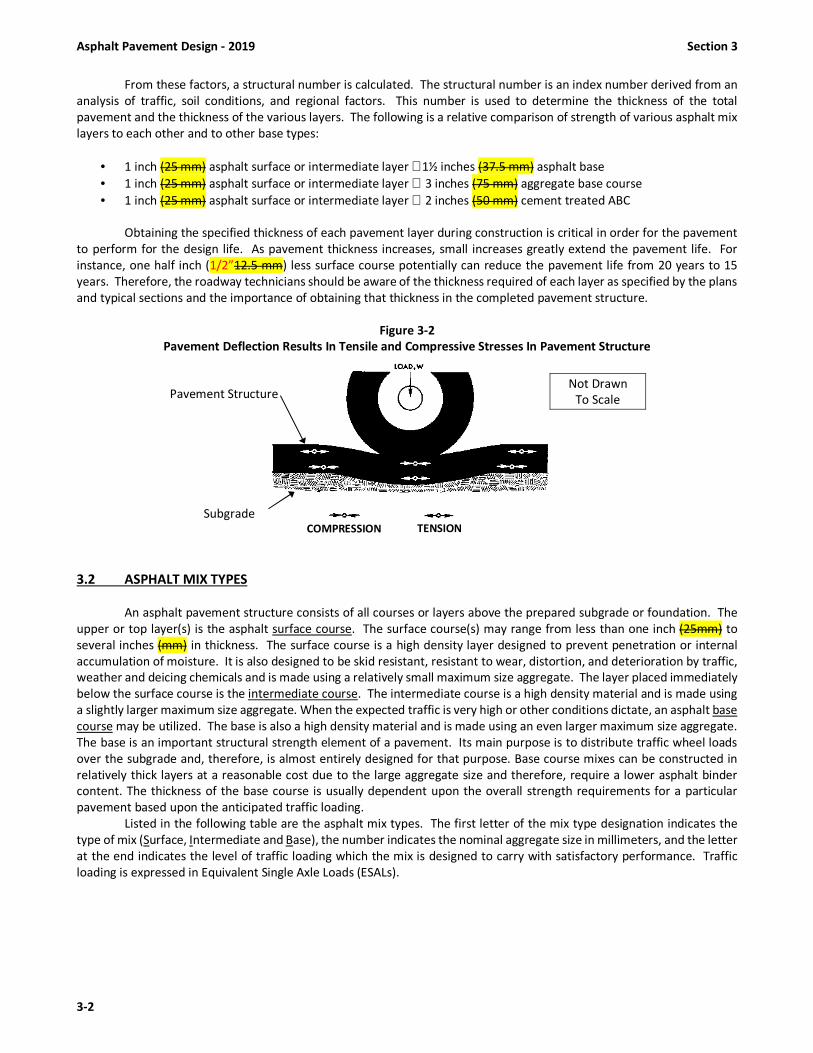
Asphalt Pavement Design - 2019 Section 3
3-2
From these factors, a structural number is calculated. The structural number is an index number derived from an
analysis of traffic, soil conditions, and regional factors. This number is used to determine the thickness of the total
pavement and the thickness of the various layers. The following is a relative comparison of strength of various asphalt mix
layers to each other and to other base types:
• 1 inch (25 mm) asphalt surface or intermediate layer ≅ 1½ inches (37.5 mm) asphalt base
• 1 inch (25 mm) asphalt surface or intermediate layer ≅ 3 inches (75 mm) aggregate base course
• 1 inch (25 mm) asphalt surface or intermediate layer ≅ 2 inches (50 mm) cement treated ABC
Obtaining the specified thickness of each pavement layer during construction is critical in order for the pavement
to perform for the design life. As pavement thickness increases, small increases greatly extend the pavement life. For
instance, one half inch (1/2”12.5 mm) less surface course potentially can reduce the pavement life from 20 years to 15
years. Therefore, the roadway technicians should be aware of the thickness required of each layer as specified by the plans
and typical sections and the importance of obtaining that thickness in the completed pavement structure.
Figure 3-2
Pavement Deflection Results In Tensile and Compressive Stresses In Pavement Structure
3.2 ASPHALT MIX TYPES
An asphalt pavement structure consists of all courses or layers above the prepared subgrade or foundation. The
upper or top layer(s) is the asphalt surface course. The surface course(s) may range from less than one inch (25mm) to
several inches (mm) in thickness. The surface course is a high density layer designed to prevent penetration or internal
accumulation of moisture. It is also designed to be skid resistant, resistant to wear, distortion, and deterioration by traffic,
weather and deicing chemicals and is made using a relatively small maximum size aggregate. The layer placed immediately
below the surface course is the intermediate course. The intermediate course is a high density material and is made using
a slightly larger maximum size aggregate. When the expected traffic is very high or other conditions dictate, an asphalt base
course may be utilized. The base is also a high density material and is made using an even larger maximum size aggregate.
The base is an important structural strength element of a pavement. Its main purpose is to distribute traffic wheel loads
over the subgrade and, therefore, is almost entirely designed for that purpose. Base course mixes can be constructed in
relatively thick layers at a reasonable cost due to the large aggregate size and therefore, require a lower asphalt binder
content. The thickness of the base course is usually dependent upon the overall strength requirements for a particular
pavement based upon the anticipated traffic loading.
Listed in the following table are the asphalt mix types. The first letter of the mix type designation indicates the
type of mix (Surface, Intermediate and Base), the number indicates the nominal aggregate size in millimeters, and the letter
at the end indicates the level of traffic loading which the mix is designed to carry with satisfactory performance. Traffic
loading is expressed in Equivalent Single Axle Loads (ESALs).
Pavement Structure Not Drawn
To Scale
Subgrade COMPRESSION TENSION

Section 3 Asphalt Pavement Design - 2019
3-3
Figure 3-3
ASPHALT MIX TYPES
Mix Type General Use ESAL Range (Million) Binder PG Grade
SA-1 Surface Course Less than 0.3 64-22
S4.75A Surface Course Less than 1.0 64-22
S9.5B Surface Course 0 to 3 64-22
S9.5C Surface Course 3 to 30 64-22
S9.5D Surface Course More than 30 76-22
I19.0C Intermediate Course ALL 64-22
B25.0C Base Course ALL 64-22
3.3 PAVEMENT LAYER DEPTH GUIDELINES (FOR PAVEMENT DESIGN PURPOSES)
Mix Type Lift Thickness (Inches)
Minimum Lift (1) Maximum Lift Normal Total Layer
SA-1 0.50 1.0 2.0
S4.75A 0.75 1.0 2.0
S9.5B 1.0 1.5 3.0
S9.5C, D 1.5 2.0 3.0
I19.0 C 2.5 4.0 4.0
B25.0 C 3.0 (2) 5.5 ---
(1) Approximate Minimum Thickness; lower rates may be used for leveling courses. (2) For B25.0C placed on unstabilized subgrade, minimum lift thickness is 4.0 in. (100 mm).
3.4 APPLICATION RATES OF SPREAD PER INCH DEPTH
Mix Type Approximate Rate (lbs/sy/in) (1) Single Layer Thickness/Rate (2)
SA-1 100 0.75 in @ 75 lbs/sy
S4.75A 110 0.75 in @ 85 lbs/sy
S9.5B 110 1.25 in @ 138 lbs/sy
S9.5C, D 112 1.50 in @ 168 lbs/sy
I19.0C 114 2.50 in @ 285 lbs/sy
B25.0C 114 3.00 in @ 342 lbs/sy
(1) Always refer to the contract and/or typical sections for the specified average rate and approximate depth.
(2) Approximate Minimum Thickness; lower rates may be used for leveling courses.

Asphalt Pavement Design - 2019 Section 3
3-4
3.5 TYPICAL ASPHALT BINDER CONTENTS (BY WEIGHT OF TOTAL MIX)
PG 64-22 PG 76-22
SA-1 6.8%
S 4.75 A 7.0%
S 9.5 B 6.7%
S 9.5 C 6.0% S 9.5 D 5.7%
I 19.0 C 4.8%
B 25.0 C 4.5%
PADC, Type P-57 2.5% OGFC, Type FC-1 Mod. 6.1%
PADC, Type P-78M 3.0%
Note: Rates and depths shown are
examples only. See specific project
Pavement Schedule for exact rates
and depths.
Example Roadway Typical Section
Pavement Schedule
(English Units)
C1
Proposed approx. 3” ACSC, Type S 9.5 C
at an average rate of 168 lbs. per sq. yd.
in each of two layers.
D1 Proposed approx. 2 1/2” ACIC, Type I 19.0 C
at an average rate of 285 lbs. per sq. yd.
E1 Proposed approx. 5” ACBC, Type B 25.0 C
at an average rate of 570 lbs. per sq. yd.
J Proposed 8” Aggregate Base Course
Section 4 Asphalt Mix Design & Job Mix Formulas - 2019
4-1
SECTION 4
ASPHALT MIX DESIGN AND JOB MIX FORMULAS
4.1 INTRODUCTION TO MIX DESIGN
As stated in Section 2, an asphalt mixture is composed of three basic components: 1) asphalt binder, 2) aggregates
and 3) air voids. Mineral filler, additives, and other modifiers are used when needed or required. The asphalt material,
which can be asphalt binder, modified asphalt binder, emulsified liquid asphalt or some other form of asphaltic material,
acts as a binding agent to glue the aggregate particles into a cohesive mass. Asphalt Concrete is a paving material that
consist primarily of asphalt binder and mineral aggregate and is mixed in an asphalt mix plant or by some other procedure.
When bound by the asphalt binder, the mineral aggregate acts as a stone framework to impart strength and toughness to
the system. Because it is relatively impervious to water, the asphalt binder also functions to waterproof the mixture.
Because asphalt mix contains both asphalt binder and mineral aggregate, the volumetric properties and subsequently the
behavior of the mixture is affected by the properties of the individual components and how they react with each other in
the system. In order to determine if the behavior and performance of the mixture under traffic will be satisfactory, a mix
design must be performed to determine the proper combination of the individual materials prior to beginning mix
production.
4.2 PURPOSES OF MIX DESIGNS
While there are many types of asphalt mixtures used in highway construction, there are three basic types: surface
mixes, intermediate mixes and base mixes. As noted above, there are certain properties and performance characteristics
that are desirable in an asphalt mix. The relative proportions of aggregate, asphalt binder, and air voids significantly affect
the physical properties of the mix and ultimately, how it will perform as a finished pavement. While it would be very easy
to "mix some asphalt with some rock", this very likely would result in a poor quality mix. Designing asphalt mixes, as with
other engineering materials designs, is largely a matter of selecting and proportioning materials to obtain the desired
qualities and properties in the finished construction. The overall objective is to determine an economical blend and
gradation of aggregates (within the specification limits) and a corresponding asphalt content that yields a mix having:
(a) Sufficient asphalt to ensure a durable pavement by thoroughly coating the aggregate particles and
waterproofing and bonding them together under suitable compaction.
(b) Sufficient mix resistance to permanent deformation to satisfy the service requirement and demands of traffic
without distortion or displacement.
(c) Sufficient voids in the total compacted mix to provide for a slight additional amount of compaction under
traffic loading without bleeding and rutting, yet be low enough to keep out excessive air and moisture.
(d) Sufficient workability to permit efficient placement and proper compaction operations without segregation.
4.3 PERFORMANCE CHARACTERISTICS CONSIDERED IN MIX DESIGN
Asphalt pavements function properly when they are designed, produced and placed in such a manner as to give
them certain desirable performance characteristics. These characteristics contribute to the quality of asphalt pavements.
These include permanent deformation (rutting) resistance, durability, flexibility, fatigue resistance, skid resistance,
impermeability, workability and economics.
Ensuring that a paving mixture has each of these properties is a major goal of the mix-design procedure. Therefore,
the technician should be aware of what each of the properties is, how it is evaluated, and what it means in terms of
pavement performance. These properties are discussed below.
4.3.1 Permanent Deformation (Rut Resistance)
The ability of an asphalt mix to resist permanent deformation from imposed loads. Unstable mixes are marked by
channeling (ruts), corrugations (washboarding), pushing and shoving in the pavement. Rut resistance is dependent upon
both internal friction of aggregate and cohesion within the mix.
Internal friction is dependent on particle shape, surface texture, gradation of aggregate, density of mix, binder
grade and quantity of asphalt. Rut resistance results from a combination of the frictional forces within the aggregate
structure and the interlocking resistance of the aggregate in the mix. Frictional resistance increases with the surface
roughness of the aggregate particles and with the area of particle contact. Interlocking resistance is dependent upon
particle size and shape.

Asphalt Mix Design & Job Mix Formulas - 2019 Section 4
4-2
Figure 4-1 Contrasting Aggregate Structures
Cubical Aggregate Rounded Aggregate
The figure above demonstrates that with more angular (cubical) particle shape and more contact between particles
greater resistance to rutting and permanent deformation is achieved. For any given aggregate, the rut resistance
increases with the density of the confined particles, which is achieved by dense gradations and adequate compaction.
Excessive asphalt in the mix tends to lubricate the aggregate particles and lower the internal friction of the stone
framework.
Cohesion is that binding force that is inherent in the asphalt mixes. The asphalt serves to maintain contact
pressures developed between aggregate particles. Cohesion varies directly with the rate of loading, loaded area, and
viscosity of the asphalt. It varies inversely with the temperature. Cohesion increases with increasing asphalt content up to
a maximum point and then decreases.
4.3.2 Durability
Durability is how well an asphalt mix resists disintegration by weathering and traffic. Included under weathering
are changes in the characteristics of asphalt such as oxidation, volatilization and changes in the pavement and aggregate
due to the action of water, including stripping, freezing and thawing. Durability is generally enhanced by high asphalt
contents, dense aggregate gradations, and well-compacted, impervious mixes. One argument for an increased amount of
asphalt is the resultant thicker asphalt film coating around the aggregate particles. Thicker films are more resistant to age-
hardening. Another reason for an increased amount of asphalt is to reduce the pore size of the interconnected voids or to
seal them off in the mix, making it more difficult for air and water to enter the interior of the mix and cause damage. To
resist the action of water, the same requirements (dense-graded aggregates, high asphalt contents, and adequate
compaction) apply. It is desirable to use aggregates that retain an asphalt coating in the presence of water.
Sufficient asphalt must be incorporated in the mix to provide bonding properties adequate to resist the abrasive
forces of traffic. Insufficient asphalt may result in aggregate being dislodged from the surface. This is known as raveling.
Abrasion may also take place if the asphalt has become brittle. Overheating of asphalt in the mixing process is a cause of
brittleness, which leads to pavement disintegration. A mix having a high asphalt content with voids completely filled with
asphalt would provide the ultimate in durability. However, this would be undesirable from the standpoint of rut resistance.
When placed in the roadway, the mix would rut and displace under traffic. Bleeding or flushing of asphalt to the surface
would also take place, thereby reducing skid resistance. Maximum rut resistance is not reached in an aggregate mass until
the amount of asphalt coating the particles has reached some critical value. Additional asphalt then tends to act as a
lubricant rather than a binder, reducing rut resistance of the mix, even though durability may be increased. It is necessary
to compromise by keeping the asphalt content as high as possible while maintaining adequate rut resistance.
4.3.3 Flexibility
This is the ability of an asphalt mix to conform to gradual settlements and movements of the base and subgrade.
Differential settlements in the fill embankment occasionally occur. Thus, it is impossible to develop uniform density in the
subgrade during construction because sections or portions of the pavement tend to compress and settle under traffic.
Therefore, the asphalt pavement must have the ability to conform to localized and differential settlement without cracking.
Generally, flexibility of the asphalt mix is enhanced by high asphalt content and relatively open-graded aggregates.
4.3.4 Fatigue (Cracking) Resistance
The ability of asphalt pavement to withstand repeated flexing of the pavement structure caused by the passage of
wheel loads. Tests have shown that the quantity of asphalt is extremely important when considering the fatigue resistance
of a pavement. As a rule, the higher the asphalt content, the greater the fatigue resistance. Tests indicate that low air-void
content asphalt mixes have more fatigue resistance than higher air-void content mixes. Well-graded aggregates that permit
higher asphalt content without causing flushing or bleeding in compacted pavement should be incorporated in the mix.

Section 4 Asphalt Mix Design & Job Mix Formulas - 2019
4-3
4.3.5 Skid Resistance
The ability of an asphalt surface, particularly when wet, to provide resistance to slipping or skidding of vehicles.
The factors for obtaining high skid resistance are generally the same as those for obtaining high stability. Proper asphalt
contents and aggregates with a rough surface texture are the greatest contributors. However, not only must the aggregate
have a rough surface texture, it must also resist polishing. Aggregates containing non-polishing minerals with different
wear or abrasion characteristics provide continuous renewal of the pavement's texture, maintaining a skid-resistant
surface. Examples of non-polishing aggregates are granites, crushed gravel, silica sands and slag. An example of a polishing
type aggregate is limestone. Mixes so rich in asphalt as to fill the voids in the compacted pavement will probably cause
asphalt to flush to the surface, which is called bleeding. Asphalt on pavement surface can cause slippery conditions.
4.3.6 Impermeability
The ability an asphalt pavement to provide resistance to the passage of air and water into or through the
pavement. While the void content may be an indication of the susceptibility of a compacted mix to the passage of air and
water; of more significance is the interconnection of voids and their access to the surface. Imperviousness to air and water
is extremely important from the standpoint of lasting durability.
4.3.7 Low Temperature / Shrinkage Cracking
The ability of an asphalt pavement to resist low temperature/shrinkage cracking. Low temperature/shrinkage
cracking is caused by adverse environmental conditions rather than applied traffic loads. It is characterized by surprisingly
consistently spaced transverse cracks (perpendicular to the direction of traffic). It is caused by a build-up of tensile stresses
as the pavement shrinks due to extremely cold weather or due to shrinkage caused by oxidation (aging) of the pavement.
Hard asphalt binders or binders which have hardened (oxidized) due to high void content in the as constructed mix are
more prone to low temperature cracking.
4.3.8 Workability
The ease with which an asphalt mix may be placed and compacted. With careful attention to proper design and
with the use of machine spreading, workability is not a problem. At times, the properties of the aggregates that promote
high rut resistance make asphalt mixes containing these aggregates difficult to spread or compact and may promote
segregation. Since workability problems are discovered most frequently during the paving operation, mix design
adjustments should be made quickly to allow the job to proceed as efficiently as possible.
4.3.9 Economics
The cost of the in-place pavement must be considered. Mix components, production and placement costs, haul
distances, safety considerations, quality, expected pavement performance and other factors need to be evaluated when
selecting the final mix design.
4.4 THE MIX DESIGN PROCESS
The mix design process is based on volumetric proportioning of the asphalt and aggregate materials and laboratory
compaction of trial mixes using the Gyratory Compactor. The basic mixture design procedures consist of an evaluation of
the following characteristics once the type and amount of traffic and the environmental conditions under which the
pavement will be expected to perform have been determined:
4.4.1 Aggregate Properties and Gradation Requirements
Aggregate physical properties for asphalt mixes are specified on the basis of both “consensus” (blend) properties
and “source” (individual) properties. These criteria are discussed in more detail in Section 2. To specify gradation, the 0.45-
power gradation chart is used with control points on various sieves to define a permissible gradation of the designated mix
type. Control points function as master ranges through which gradations must pass. Control points are placed at the
nominal maximum size sieve, an intermediate size sieve (2.36 mm), and the smallest sieve (0.075 mm). The control points
vary, depending on the nominal maximum size of the mix. This chart uses a unique graphing technique to judge the
cumulative particle size distribution of an aggregates blend. The vertical axis of the chart is the percent passing. The
horizontal axis is an arithmetic scale of sieve sizes in millimeters, raised to the 0.45 power.

Asphalt Mix Design & Job Mix Formulas - 2019 Section 4
4-4
An important feature of the 0.45-power chart is the maximum density gradation. This gradation plots as a straight
line from the maximum aggregate size through the origin and uses the following definitions with respect to aggregate size:
Maximum Size: One sieve size larger than the nominal maximum size.
Nominal Maximum Size: One sieve size larger than the first sieve to retain more than 10%
(Mix types are defined in terms of their nominal maximum aggregate size;
for example, an I 19.0C mix has a nominal maximum aggregate size of 19.0 mm.)
The maximum density gradation represents a gradation in which the aggregate particles fit together in their most
dense possible arrangement. In general, this is a gradation to avoid because there will most likely be inadequate void space
within the aggregate structure to allow adding adequate asphalt binder in order to develop sufficiently thick asphalt films
for a durable mixture and still maintain the desired air void content. The design gradation should lie between the control
points and meet the aggregate gradation requirements detailed in Table 610-2.
4.4.2 Asphalt Binder Grade Selection and Requirements
The binder grade selection process utilizes procedures that directly relate laboratory analysis with laboratory
performance. In general, mix design guidelines specify that the binder grade to be used in a mix be initially selected based
on the climate (average high and average low temperatures), in which the pavement will be performing. The designation,
called Performance Grading (PG) contains two temperatures: the average 7 day high pavement temperature and the
average 7 day low temperature. The high temperature is important because rutting failure occurs when the pavement is
hot and becomes soft. The low temperature number indicates the low temperature cracking properties of the binder. The
lower the second number, the greater the ability the binder has to resist cracking due to shrinkage caused by freeze/thaw
cycles. See Table 610-3 for the PG grade required for the various mix types specified by NCDOT.
PG 64-22 is the “standard” grade for North Carolina based on climatic conditions.
4.4.3 Mixture Volumetric Properties and Requirements
A major factor that must be taken into account when considering asphalt mixture behavior is the volumetric
properties of the mixture. Mixture volumetric requirements consist of air voids (VTM), voids in the mineral aggregate
(VMA), voids filled with asphalt (VFA) and effective asphalt content (Pbe). These volumetric properties for NCDOT mixes are
illustrated in Figure 4-2.
Air void content (VTM) is an extremely important property because it is used as the basis for selecting the asphalt
binder content. The design air void content is usually 4.0%; however, the mix designer should always check the
specifications.
Voids in the mineral aggregate (VMA) is defined as the sum of the volume of air voids and effective (i.e.,
unabsorbed) binder in a compacted sample. It represents the void space between the aggregate particles. Specified
minimum values for VMA at the design air void content of 4.0% are a function of nominal maximum aggregate size. Table
610-3 shows mix VMA requirements.
Voids filled with asphalt (VFA) is defined as the percentage of the VMA containing asphalt binder. Consequently,
VFA is the volume of effective asphalt binder expressed as a percentage of the VMA. The acceptable range of design VFA
is a function of traffic level as shown in Table 610-3. Effective asphalt content (Pbe) is defined as the total asphalt content
of a paving mixture minus the portion of asphalt absorbed into the aggregate particles (see Fig. 4-3).
Obtaining the correct air void content is critical in both mix design and the in-service performance of a pavement.
As discussed in Section 2, asphalt binder expands and contracts with variations in temperature. In hot weather, air voids in
the mix provide room for the expanding asphalt binder. If there are not enough voids within the mix to allow for the
expansion, the asphalt binder expands to fill all existing voids, and then begins pushing the aggregate particles apart,
reducing aggregate interlock and contact friction. This causes the pavement to become unstable, more susceptible to
pushing, shoving, and rutting. The binder eventually may bleed or flush to the surface. This significantly reduces the skid
resistance of the pavement.
Imperviousness to air and water is extremely important for the mix to be and remain durable. If the air void content
is too high, the air voids may interconnect and allow water and air to penetrate into the mix. Water penetration may cause
the asphalt binder to strip from the aggregate. Exposing asphalt binder to both water and air will cause it to oxidize more
rapidly, causing it to become hard and brittle, and therefore resulting in early fatigue failure.

Section 4 Asphalt Mix Design & Job Mix Formulas - 2019
4-5
4.4.4 Dust to Effective Binder Ratio
Another mixture requirement is the dust to effective binder ratio. This is computed as the ratio of the percentage
by weight of aggregate finer than the 0.075 mm sieve (by washing) to the effective asphalt content expressed as a percent
by weight of total mix. Effective binder content is the total binder used in the mixture less the percentage of absorbed
binder. Dust / Binder Ratio is used during the mixture design phase as a design criteria. See Table 610-3 for the required
Dust / Binder Ratio for the various mix types specified by NCDOT.
4.4.5 Moisture Susceptibility
Moisture Susceptibility, also known as stripping, is the separation of the asphalt film from the aggregate through
the action of water and may make an aggregate material unsuitable for use in asphalt paving mixes. Such material is referred
to as hydrophilic (water loving). Siliceous aggregates such as quartzite and some granites are examples of aggregates that
may require evaluation of stripping potential. Aggregates that exhibit a high degree of resistance to asphalt film stripping
in the presence of water are usually most suitable in asphalt paving mixes. Such aggregates are referred to as hydrophobic
(water hating) aggregates. Limestone, dolomite, and traprock are usually highly resistant to asphalt film stripping. Why
hydrophobic or hydrophilic aggregates behave as they do is not completely understood. The explanation is not as important
as the ability to detect the properties and avoid use of aggregates conductive to asphalt stripping.
The moisture susceptibility test used to evaluate asphalt mix for stripping is NCDOT-T-283. This test serves two
purposes. First, it identifies whether a combination of asphalt binder and aggregate is moisture susceptible. Second, it
measures the effectiveness of anti-stripping additives.
4.4.6 Permanent Deformation (Rut Resistance)
One of the major objectives of mix design is to provide pavements which would be highly resistant to permanent
deformation (rut resistance). As stated earlier, rut resistance is the ability of an asphalt mix to resist permanent deformation
from imposed loads. This is especially important for surface mixes since this is where the wheel loads are concentrated and
the potential for rutting is greatest. The aggregate and binder specifications are established such that a rut resistant mix
should be obtained; however, once a mix has been designed based on the specified criteria, the mix should be physically
tested to evaluate the anticipated performance under traffic. To accomplish this objective the Department will perform rut
resistance evaluation on surface mix specimens prepared by the Contractor as a part of the mix design process. In addition to the required mix design submittal forms, the Contractor will prepare and deliver six (6) Gyratory
Compactor specimens to the Department’s Central Asphalt Laboratory for the following surface mix types: S4.75A, S9.5B,
S9.5C, and S9.5D. The Contractor will prepare these specimens using lab produced mix in accordance with NCDOT-T-312.
These specimens shall be compacted to a height of 75 ± 2 mm and to a void content (VTM) of 4.0% ± 0.5% (except, S4.75A
rut specimens should be compacted to a VTM of 5.0% ± 0.5%). These specimens will be tested for rutting susceptibility
using the Asphalt Pavement Analyzer in the Materials and Tests Central facility. The maximum rut depth allowed for the
various surface mixes is specified in Table 610-3.

Asphalt Mix Design & Job Mix Formulas - 2019 Section 4
4-6
MIXTURE VOLUMETRIC PROPERTIES AND RELATIONSHIPS
Figure 4-2
Illustration of VMA in a Compacted Mix Specimen
(Note: For simplification the volume of absorbed asphalt is not shown.)
Figure 4-3 Diagram Illustrating the Air Voids and Voids in Mineral Aggregate (VMA)
4.5 NCDOT MIX DESIGN PROCEDURES
The Contractor is required to design the asphalt mix and to obtain an approved Job Mix Formula (JMF) issued by
the Department. A mix design and proposed JMF targets for each required mix type and combination of aggregates must
be submitted both in writing and in electronic format to the NCDOT Asphalt Mix Design Engineer for review and approval
at least 10 days (at least 20 days for OGFC and UWBC mixes) prior to start of asphalt mix production.
The mix design must be prepared in an approved mix design laboratory by a certified Mix Design Technician. The
design laboratory must be approved by the Asphalt Mix Design Engineer prior to submission of the mix design. The mix
design shall be prepared in accordance with AASHTO R 35, “Superpave Volumetric Design for Asphalt Mixtures” as modified
by the Department, recommended procedures in the latest edition of the Asphalt Institute publication “MS-2: Asphalt Mix
Design Methods” and the latest edition of Department mix design computer programs, policies, procedures, and forms.
The request for the AMD/JMF approval will be submitted to the Asphalt Mix Design Engineer on Form QMS-1 with attached
design data, proposed JMF target values, and forms as noted. In addition, the Contractor is required to submit the design
data in electronic form using the Department’s mix design program.

Section 4 Asphalt Mix Design & Job Mix Formulas - 2019
4-7
Prepare all proposed mix design data in accordance with Department policies and procedures including but not
limited to, the following information:
(1) Source and percentage of each aggregate component to be used in the design aggregate blend gradation, including
RAP and RAS.
(2) Percentage of asphalt binder in RAP and RAS.
(3) Gradation of each aggregates component, including RAP and RAS.
(4) The following aggregate properties: current bulk specific gravity (Gsb), current apparent specific gravity (Gsa) and
absorption of the individual aggregate components to be used when tested in accordance with AASHTO T84 and
T85, except report the effective bulk specific gravity (Gse) of RAP and RAS aggregate as determined by NCDOT-T-
209. Report coarse aggregate angularity, fine aggregate angularity, flat and elongated percentages, and sand
equivalent for the total aggregate blend.
(5) Source(s), modification method, and percent of modifier by weight of asphalt binder, if modified.
(6) Supplier, source, grade, and equi-viscous mixing and compaction temperatures of the asphalt binder. Include a
copy of the binder producer’s Certificate of Analysis (COA) showing test data for Determine equi-viscous
temperatures using the rotational viscometer testing in accordance with ASTM D4402 corresponding to the
following recommended viscosity ranges:
Range for mixing = 0.150 to 0.190 Pa-s
Range for compaction = 0.250 to 0.310 Pa-s
When PG 76-22 or other modified binders are used, base the temperatures on the documented supplier’s
recommendations.
(7) Brand name, manufacturer, shipping point, and percentage of anti-strip additive used in the mix design. Determine
TSR data in accordance with NCDOT-T-283.
(8) Target value for percent passing each standard sieve for the design aggregate gradation. Data will show the
percent passing for all standard sieves listed in Table 610-2 for the specified mix type. Show the percentages in
units of one percent of aggregate passing, except for the 0.075 mm (No. 200) sieve, show in units to one-tenth of
one percent. Base percentages on the dry weight of aggregate determined in accordance with NCDOT-T-11 and
NCDOT-T-27.
(9) Volumetric properties of the compacted mixture calculated on the basis of the mixture's maximum specific gravity
as determined by NCDOT-T-209. The mixture shall be aged in accordance with AASHTO R 30 and the bulk specific
gravity of specimens determined by NCDOT-T-166 or NCDOT-T-331, for each asphalt content tested. Determine
and report properties in accordance with the requirements of AASHTO R 35 except as modified herein, and
Department Mix Design Policies and Procedures.
(10) Graphical plots of percent asphalt binder by total weight of mix (Pb) versus the following properties at the design
number of gyrations, Ndes, specified:
(a) SGC bulk gravity, Gmb @ Ndes
(b) % Gmm @ Nini
(c) Voids in total Mix (VTM)
(d) Voids Filled with Asphalt (VFA)
(e) Voids in Mineral Aggregate (VMA)
(f) % Compaction vs. Log of Gyrations
(11) Graphical plot of the design aggregate gradation (design blend) on FHWA 0.45 power chart showing the applicable
control points, and maximum density line. Plot all standard sieves for the applicable mix type.
(12) Proposed target value of asphalt binder content by weight of total mix and specification design properties at that
percentage.
(13) TSR test data in accordance with NCDOT-T-283.
When the mix design is submitted, include the original recording charts detailing the TSR results to the Asphalt Mix
Design Engineer in accordance with Section 7.14. In addition, when requested by the Asphalt Mix Design Engineer, the
Contractor must submit representative samples of each mix component, including RAP, RAS, mineral filler, asphalt binder,
chemical anti-strip additive and hydrated lime to the Department’s mix design laboratory.
In addition, the Contractor will prepare and deliver six (6) Gyratory Compactor specimens to the Department’s
Central Asphalt Laboratory for the following surface mix types: S4.75A, S9.5B, S9.5C, and S9.5D. These specimens are used
for rut testing.

Asphalt Mix Design & Job Mix Formulas - 2019 Section 4
4-8
4.6 THE JOB MIX FORMULA
All asphalt plant mixes, either virgin or recycled, be proportioned and graded such that they meet the requirements
of a job mix formula approved and issued by the Department. This job mix formula will be based on a mix design performed
by the Contractor and approved by the Materials and Tests Asphalt Lab. Once the Asphalt Mix Design Engineer has evaluated
and/or confirmed the data, the mix design will be approved if it meets specifications. The mix design and job mix formula
target values must be within the design criteria for the particular type of asphalt mixture specified. The source and grades
of material, blend proportions of each of the various aggregates used, specific gravity information, and other applicable
data and notes will be given on the formula. Specific details on “Master” job mix formula procedures are discussed below.
Once the JMF has been approved and production is ready to begin, the component materials must be combined
in such proportions that the completed mixture meets the specification requirements for the particular mix type specified.
During production the materials are heated and blended together in an asphalt mix plant such that the mixture is uniformly
mixed and coated with asphalt binder. The mixture is then transported to the roadway where it is spread, finished and
compacted to the required grades, thickness and typical section required by the plans and contract.
The job mix formula (JMF) gradation target values will be established within the design criteria specified for the
particular type of asphalt mixture to be produced. The JMF asphalt binder content will be established at the percentage
which will produce voids in total mix (VTM) at the midpoint of the specification design range for VTM, unless otherwise
approved. The formula for each mixture will establish the following: blend percentage of each aggregate fraction, the
percentage of reclaimed aggregate, if applicable, a single percentage of combined aggregate passing each required sieve
size, the total percentage (by weight of total mixture) and grade of asphalt binder required for that mix type as in Table
610-3 unless otherwise approved by the Engineer, the percentage and grade of asphalt binder actually to be added to the
mixture (for recycled mixtures), the percentage of chemical anti-strip additive to be added to the asphalt binder or
percentage of hydrated lime to be added to the aggregate, the temperature at which the mixture is to be discharged from
the plant, the required field density, and other volumetric properties.
The mixing temperature during production at the asphalt plant will be established on the job mix formula. The
mixing temperature is based on the grade of asphalt binder required for a specific mix type as in Table 610-3, unless
otherwise approved by the Engineer. The mixing temperatures will be different depending on which grade of asphalt binder
is being used.
At the end of this section are examples of the currently approved computer generated mix design forms and
supporting mix design data forms for the Contractor's use in preparing and submitting Mix Design/JMF request. The
Contractor is required to use and therefore, must obtain from the Department, at no charge, the Mix Design computer
spreadsheet program that will perform the calculations and generate the completed forms once the appropriate data has
been entered. To obtain a copy of this spreadsheet, contact the Asphalt Mix Design Engineer at (919) 329-4060.
TABLE 610-2
AGGREGATE GRADATION CRITERIA
(Percent Passing Control Points)
Standard
Sieves (mm)
Mix Type (Nominal Max. Aggregate Size)
4.75 mm 9.5 mmA 19.0 mm 25.0 mm
Min Max Min Max Min Max Min Max
50.0 - - - - - - - -
37.5 - - - - - - 100 -
25.0 - - - - 100 - 90.0 100
19.0 - - - - 90.0 100 - 90.0
12.5 100.0 - 100 - - 90.0 - -
9.50 95.0 100.0 90.0 100 - - - -
4.75 90.0 100.0 - 90.0 - - - -
2.36 - - 32.0B 67.0B 23.0 49.0 19.0 45.0
1.18 30.0 60.0 - - - - - -
0.075 6.0 12.0 4.0 8.0 3.0 8.0 3.0 7.0
A. For the final surface layer of the specified mix type, use a mix design with an aggregate blend gradation
above the maximum density line on the 2.36 mm and larger sieves.
B. For Type S9.5B, the percent passing the 2.36 mm sieve shall be a minimum of 60% and a maximum of
70%.

Section 4 Asphalt Mix Design & Job Mix Formulas - 2019
4-9
TABLE 610-3
MIX DESIGN CRITERIA
Mix
Type
Design
ESALs
millions A
Binder
PG
Grade B
Compaction
Levels
Max.
Rut
Depth
(mm)
Volumetric Properties
Gmm @ VMA VTM VFA %Gmm
@ Nini Nini Ndes % Min. % Min.-Max.
S4.75A < 1 64 - 22 6 50 11.5 16.0 4.0 - 6.0 65 - 80 ≤ 91.5
S9.5B 0 - 3 64 - 22 6 50 9.5 16.0 3.0 - 5.0 70 - 80 ≤ 91.5
S9.5C 3 - 30 64 - 22 7 65 6.5 15.5 3.0 - 5.0 65 - 78 ≤ 90.5
S9.5D > 30 76 - 22 8 100 4.5 15.5 3.0 - 5.0 65 - 78 ≤ 90.0
I19.0C ALL 64 - 22 7 65 - 13.5 3.0 - 5.0 65 - 78 ≤ 90.5
B25.0C ALL 64 - 22 7 65 - 12.5 3.0 - 5.0 65 - 78 ≤ 90.5
Design Parameter Design Criteria
All Mix
Types
Dust to Binder Ratio (P0.075 / Pbe) 0.6 - 1.4 C
Tensile Strength Ratio (TSR) D 85% minimum E
A. Based on 20 year design traffic.
B. Volumetric Properties based on specimens compacted to Ndes as modified by the Department.
C. Dust to Binder Ratio (P0.075 / Pbe) for Type S4.75A is 1.0 - 2.0.
D. NCDOT-T-283 (No Freeze-Thaw cycle required).
E. TSR for Type S4.75A & B25.0C mixes is 80% minimum.
TABLE 610-4
MAXIMUM RECYCLED BINDER REPLACEMENT PERCENTAGE (RBR%)
Recycled Material Intermediate & Base Mixes Surface Mixes Mixes Using
PG 76-22
RAS 23% 20% 18%
RAP or RAP/RAS
Combination 45% 40% 18%
TABLE 610-5
BINDER GRADE REQUIREMENTS (BASED ON RBR%)
Mix Type %RBR ≤ 20% 21% ≤ %RBR ≤ 30% %RBR > 30%
S4.75A,
S9.5B, S9.5C
I19.0C, B25.0C
PG 64-22 PG 64-22 A PG 58-28
S9.5D, OGFC PG 76-22 B n/a n/a
A. If the mix contains any amount of RAS, the virgin binder shall be PG 58-28.
B. Maximum Recycled Binder Replacement (%RBR) is 18% for mixes using PG 76-22 binder.

Asphalt Mix Design & Job Mix Formulas - 2019 Section 4
4-10
4.7 NCDOT "MASTER" JOB MIX FORMULA PROCEDURES
Once a mix design for a specified mix type has been approved, and if the Asphalt Mix Design Engineer is in
concurrence with the design and proposed target values, the JMF data will be entered into the NCDOT HiCAMS computer
system. This "Master" JMF will be for a specific plant and will serve for all projects on which that given JMF for the specified
mix type is to be used. The Contractor will then place one copy of this AMD/JMF assembly on file at the asphalt plant QC
field laboratory for use by all QMS personnel. It is suggested that a bulletin board, preferably with a glass enclosure or a
durable notebook with transparent plastic sheeting be used for this purpose. In situations where the JMF is to be used for
DOT work and no lab is present, the JMF should be placed on file in the plant control room.
This is the JMF that both the Contractor QC and the DOT QA personnel will be using for producing and testing the
mixture, respectively. This JMF will possibly be used for a significant period of time and must be kept in a safeguarded
manner. This posted copy will be readily available to all QC/QA personnel and will also serve for all projects until voided or
revisions are authorized by the Asphalt Mix Design Engineer or his representative.
When the Contractor is ready to begin producing mixture, he will advise the Pavement Specialist which JMF he
intends to produce. Inasmuch as there will very likely be several valid JMF's for a given mix type at each plant using different
material sources and combinations, the Contractor must use caution to ensure that the appropriate materials as required
by the formula are being used. In addition, he must ensure that the latest version of the formula is being used and the
correct JMF number is being recorded on weight tickets. The Department will compare its test results with this JMF for
compliance with specifications.
As a JMF is revised in the field for whatever reasons, the Asphalt Mix Design Engineer will send to the Contractor
an updated copy showing the revisions and the effective date. The Contractor must make certain that these updated copies
are posted in the field lab as quickly as possible and that the voided copies are removed. (There may be situations where
verbal approval is given by the Asphalt Laboratory prior to the actual posting of the JMF data). While it would be desirable
to have the valid JMF posted at the plant at all times, it is realized that delays due to mailing will occur. Verbal approval
can be given in these situations but everyone must strive to keep this to a minimum. Master Job Mix Formulas for the
standard mix types covered by the specifications will not be issued directly by the Asphalt Mix Design Engineer for a specific
project unless some special circumstance exists.
Included in this Manual are examples of both virgin mix JMF's and recycled mix JMF's. Note that the owner's name,
plant location, and plant certification number shown on the JMF are the same as shown on the plant certification certificate.
JMF's will indicate a specific anti-strip additive supplier, brand, and rate and must be used unless otherwise approved by
the Engineer.
4.8 COMPOSITION OF RECYCLED MIXTURES (JOB MIX FORMULA)
When the Contractor elects to use a recycled mixture on a project, he must submit to the Department's Materials
and Tests Unit his proposed mix design and JMF target values in accordance with Article 610-3 of the Standard Specifications
and this Manual. The reclaimed asphalt materials (RAP or RAS) shall be tested for the following properties: (1) asphalt
content, (2) aggregate gradation, (3) aggregate effective specific gravity, and (4) performance grade (PG) of the RAP/RAS
asphalt (shown in blending charts), when required.
The gradation of the reclaimed aggregates is analyzed to determine the gradation of the virgin aggregates required.
Using the gradation of the aggregate from the RAP material and the new aggregates, the approved design lab will design a
combined gradation meeting the specifications. The asphalt content of the RAP material is used to determine the amount
of asphalt binder to be added in the recycled mixture. The performance grade parameters of the asphalt in the RAP/RAS
material will determine the required grade of the additional asphalt binder in the recycled mixture. The new asphalt binder
added to the recycled mix serves two purposes. It increases the total asphalt content to meet the requirements of the mix
and it blends with the aged asphalt in the reclaimed portion of the mix to yield an asphalt meeting the desired specifications.
Reclaimed Asphalt Pavement (RAP) or Reclaimed Asphalt Shingles (RAS) may be incorporated into asphalt plant
mixes in accordance with Article 1012-1 and the following applicable requirements. However, use of RAP materials is not
allowed in Open Graded Friction Course (OGFC) mixes or Ultra-Thin Bonded Wearing Course (UBWC) mixes. Use of RAS
materials is not allowed in Ultra-Thin Bonded Wearing Course (UBWC) mixes. RAS material may constitute up to 6% by
weight of total mixture, except for Open Graded Friction Course (OGFC) mixes, which are limited to 5% RAS by weight of
total mixture. Also, when the percentage of RAP is greater than 30% by weight of total mixture, use Fractionated RAP (FRAP)
meeting the requirements of Subarticle 1012-1(F)(c).

Section 4 Asphalt Mix Design & Job Mix Formulas - 2019
4-11
When RAP, RAS, or a combination of both is used in asphalt mixtures, the recycled binder replacement percentage
(RBR%) shall not exceed the amounts specified in Table 610-4 for the mix type. For recycled mixtures, the virgin binder
Performance Grade (PG) grade to be used is specified in Table 610-5 for the mix type based on the recycled binder
replacement percentage (RBR%).
If the Contractor wishes to submit mix designs containing recycled material amounts exceeding the specified
maximums, additional testing will be required to verify the Performance Grade (PG) of the reclaimed binder. Also, the
Contractor has the option to have additional testing performed to determine if the mix can be approved using a virgin
binder grade different than specified in Table 610-5. The Engineer will determine if the binder grade is acceptable for use
based on the test data submitted with the mix design. If the mix design is acceptable, the Engineer will establish and approve
the grade and percentage of virgin asphalt binder to be used.
If a change in the source of RAP or RAS be made, a new mix design and JMF may be required in accordance with
Article 1012-1. Samples of the completed recycled mixture may be taken by the Department on a random basis to determine
the PG grading on the recovered asphalt binder in accordance with AASHTO M 320/M 332. If the grading is determined to
be a value other than required for the specified mix type, the Engineer may require the Contractor to adjust any
combination of the grade, the percentage of additional asphalt binder or the blend of reclaimed material 1 to bring the
grade to the specified value.
Once the total asphalt demand has been determined, the amount of new asphalt binder to be added in the recycled
mixture is then calculated. This quantity equals the calculated asphalt demand minus the percentage of asphalt in the
reclaimed asphalt pavement. Trial mix designs are then made using the mix design procedures to determine the estimated
design asphalt content. The same design criteria are used for recycled mixes as are used with virgin mixes of the same type.
The Job Mix Formula will establish the percentage of reclaimed aggregate, the percentage of each additional
aggregate required, a single percentage of combined aggregate passing each sieve size, the total percentage of asphalt
binder in the mixture, a single percentage of additional asphalt material to be added, the percentage of chemical anti-strip
additive to be added to the additional asphalt material or percentage of hydrated lime to be added to the aggregate, a
single temperature at which the mixture is to be discharged from the plant, the required field density, and other volumetric
properties. In addition, the Job Mix Formula will establish the blend ratio and percent binder in the RAP. Should a
change in the source of virgin aggregate be made, a new job mix formula will be required before the new mixture is
produced. Should a change in the source or properties of the RAP be made, a new mix design and/or JMF may be required
based on the requirements of Article 1012-1 of the Standard Specifications (see Section 8.3). Samples of the
completed recycled asphalt mixture may be taken by the Department on a random basis to determine the performance
grading on the recovered asphalt binder in accordance with AASHTO M 320/M 332. If the viscosity is determined to be out
of this specified range, the Engineer may require the Contractor to adjust the additional asphalt material formulation and/or
blend of reclaimed material to bring the viscosity within the allowable range.
4.9 PROJECT FILE JOB MIX FORMULA PROCEDURES
Job Mix Formulas (JMF) are maintained in the Highway Construction and Materials System (HiCAMS), including
revised and voided JMF’s. HiCAMS automatically pulls information from the JMF to calculate the quantity of asphalt binder
to be paid based upon the quantity of plant mix material placed and JMF in effect at the time the work is performed. Since
copies of those JMF can be obtained at any time, the Resident Engineer is not required to maintain paper copies of the JMF
within the project Files.
When a given JMF is revised, the void date will be entered on the voided formula by the Asphalt Mix Design
Engineer and this date will appear on all copies obtained through the computer after that date. The new or revised JMF
will show the new number assigned and the effective date. This new JMF will be entered into the computer system and
the cycle repeated as noted in the "Master" JMF procedures. Again, it is critical that the QC technician has the correct JMF
number and shows same on his daily reports. If the JMF is revised, the technician at the plant will be advised of the new
JMF number at that time and will note the revised number and date on the copy posted at the plant. This revised JMF will
be used until the Contractor receives and posts the new JMF at the plant.
A listing of all Job Mix Formulas issued to a specific asphalt plant can be obtained from the Materials and Tests
Asphalt Laboratory. It should be noted that this listing shows all Job Mix Formulas issued to a plant including any "voided"
formulas. Therefore, everyone must be careful to assure that the Contractor is using the most current JMF and not a voided
formula.

Asphalt Mix Design & Job Mix Formulas - 2019 Section 4
4-12
4.9.1 Mix Type Designations
Virgin Recycled Asphalt Concrete Surface Course, Type SA-1 SA-1 RSA-1
Asphalt Concrete Surface Course, Type S 4.75 A S 4.75A RS 4.75A
Asphalt Concrete Surface Course, Type S 9.5 B S 9.5B RS 9.5B Asphalt Concrete Surface Course, Type S 9.5 C S 9.5C RS 9.5C Asphalt Concrete Surface Course, Type S 9.5 D S 9.5D RS 9.5D
Asphalt Concrete Intermediate Course, Type I 19.0 C I 19.0C RI 19.0C
Asphalt Concrete Base Course, Type B 25.0 C B 25.0C RB 25.0C
4.9.2 Job Mix Formula Numbering System
Job Mix Formula numbers will be 9 digits with a 4 character code at the end. This is the number shown on the JMF posted
at the plant and shown on all appropriate reports. Job Mix Formulas are accessible via HiCAMS.
Ex: xx-yyyy-abc-defg where: xx = Calendar Year
yyyy = Sequential number assigned by HiCAMS System
a = plant number, (1 for 1st plant 2 for a 2nd plant, etc.)
b = anti-strip percentage (2 for 0.25%, 5 for 0.5% etc.)
c = JMF revision number
defg = Code for Mix Type (see the following Table)
CODE Mix Type Description CODE Mix Type Description
HMAC Hot-Mix Asphalt Concrete [Default] WMDB Warm Mix Astec Double Barrel Green
WM3G Warm Mix Evotherm 3G
MRAS Manufacturer RAS WMU3 Warm Mix Evotherm U3
PRAS Post-Consumer RAS WMUF Warm Mix Gencor Ultrafoam
RPAS RAP-RAS Mixture WMHT Warm Mix Honeywell Titan
WMAC Warm Mix Ad-Here 62-40 + CecaBase RT
RP15 RAP Mix 15% WMLC Warm Mix LOF6500 + CecaBase RT
RP20 RAP Mix 20% WMAB Warm Mix Maxam AquaBlack
RP21 RAP Mix 21% WMAF Warm Mix Meeker AquaFoam
RP25 RAP Mix 25% WMHG Warm Mix Meridian Hydrogreen
RP30 RAP Mix 30% WMSB Warm Mix Sasol Sasobit
RP40 RAP Mix 40% WMAD Warm Mix PQ Corp. Advera
RP45 RAP Mix 45% WMTX Warm Mix Terex WMA
DC78 Permeable Asphalt Drainage Course, Type P-78M UBWC Ultra-thin Bonded Wearing Course
DC57 Permeable Asphalt Drainage Course, Type P-57
MCS2 Micro-surfacing, Type II FC1A OGFC Type FC-1 w/Additive
MCS3 Micro-surfacing, Type III FC1F OGFC Type FC-1 w/Fibers
SSTB Slurry Seal, Type B FC1S OGFC Type FC-1 w/Shingles
SSTC Slurry Seal, Type C

Section 4 Asphalt Mix Design & Job Mix Formulas - 2019
4-13

Asphalt Mix Design & Job Mix Formulas - 2019 Section 4
4-14
4.10 ASPHALT MIX DESIGN AND TESTING CALCULATIONS/FORMULAS
(from Asphalt Institute’s, SP-2, 3rd ed.)
1. Combined Aggregate Bulk Specific Gravity (Gsb):
��� = ��� = 100%���.#1������. #1 + %���. #2������. #2 +⋯+ %���.#�������. #�
= �� + �� +⋯+�� ���� +���� +⋯+ ����
2. Effective Specific Gravity of Aggregate Using Rice MSG (Gse):
��� = ���. �� = 100 −%������100� !. �� − %��������������
= �"" −���""�"" −����#ℎ���, �"" = 100
3. Maximum Specific Gravity of Mix With Different Binder Contents (Gmm):
�"" = � !. �� = 100%���.���.���. �� + %��������������
= �""����� +����
#ℎ���, �"" = 100
4. % Asphalt Absorption by Weight of Total Aggregate (Pba):
��& = 100 '(���. ��) −(���.�*+,��)(���.�*+,��)(���. ��) - (��������) = 100 .��� −���(���)(���)/ ��
5. % Effective Binder Content (by Weight of Total Mixture) (Pbe):
��� = %������ −.%�01. ������100 (%���. )/ = �� − .��&100 (��)/
6. Percent Voids in Mineral Aggregate (VMA) in Compacted Mixture:
2�� = 100 −'(3 0��)(%���. )���.�*+,�� - = 100 −4�"������ 5 #ℎ���, �� = %���. 06#7. 8�787 +9�!
Note: NCDOT Mix Composition is by Weight of Total Mixture: Example: 6.0% binder is by weight of total mixture.
7. Percent Air Voids (Va) in Compacted Mixture or Voids in Total Mix (VTM):
2:� = 100 (� !. �� − 3 0��)(� !��) = 100 4�"" −�"��""
5
8. % Voids Filled with Asphalt (VFA) in Compacted Mixture:
2;� = 100%28+. ������(����<7�=�)%2�� = 100 (2�� − 2:�)
2��

Section 4 Asphalt Mix Design & Job Mix Formulas - 2019
4-15
9. Bulk Specific Gravity of Compacted Mix Specimen or Core (Gmb):
�"� = >���ℎ7�����(��?>���ℎ7 −>���ℎ7��> 7��) = �
� − @(��89:166)
10. Unit Weight Total Mix (γγγγm):
B" = C��7>���ℎ7(+0 �7D⁄ ) =(��!��)(BF&G�H) = �"�(62.4)#ℎ���, C��7>7. 8�> 7��(BF&G�H) = 62.4 +0 �7D⁄
11. % Solids by Volume Total Mix (Psolids):
��JKLM� = 3 0��� !�� × 100 = �"��""× 100
12. Percent Asphalt Absorption by Weight of Total Mixture (P’ba):
�′�& =(%�������018�P7�8�06>7. 8����. ) (%���. )100 = ��& 4 ��1005 #ℎ���, �� = %���. 06#7. 8�787 +9�!
13. Percent by Volume of Effective Binder (Vbe):
2�� = %28+. (���. )������ = (%���.������06>7. )(3 0��)(��������) = (���)(�"�)��
14. % Solids by Volume of Aggregate Only (P(solids-agg.only)):
��JKLM�Q&RR.J�KS = %�8+��10628+*9�:87 +��! − %28+*9�(����<7�=�)������ = ��JKLM� −2��
15. % Binder (Back Calculated from Rice SG) (Pb)*:
�� = (100)(��������) .4���. ��� !. ��5 − 1/
(���. �� − ��������) = 100�� TU����""V − 1W
(��� −��)
*Note: Cannot be used when Eff. S.G. is computed from the same Rice Test.
17. General Voids In Mineral Aggregate Relationship:
2�� = %���28��1 + %���. ������0628+. = 2:� +2��
18. Dust/Binder Ratio P0.075/Pbe:
?*17/������Y 7�8 = Z[.[\]Z^_ Where: P0.075 = % Passing 0.075mm (#200) Sieve by Washing
Pbe = % Effective Binder by Wt. of Total Mixture

Asphalt Mix Design & Job Mix Formulas - 2019 Section 4
4-16

Section 5 Asphalt Plant Equipment - 2019
5-1
SECTION 5
ASPHALT PLANT EQUIPMENT
5.1 BASIC OPERATION OF AN ASPHALT PLANT
Asphalt paving mixes made with asphalt binder are prepared at an asphalt mixing plant. Aggregates are blended,
heated and dried, and mixed with asphalt binder to produce a hot asphalt paving mixture. The mixing plant may be small
and simple or it may be large and complex, depending on the type and quantity of asphalt mixture being produced. The
plant may be stationary (permanent) or portable.
5.2 TYPES OF ASPHALT PLANTS
Asphalt plants are basically of three general types:
(1) Batch plant; (2) Drum mix plant; (3) Continuous mix plant
However, the two most common types of asphalt plants are batch plants and drum mix plants and will be
discussed in detail in this manual. Continuous mix plants are not covered, since these are very similar to Batch Plants. They
are essentially batch plants that are controlled by the cold feeds.
5.3 CERTIFICATION OF ASPHALT PLANTS
All plants used to produce asphalt mix for NCDOT projects are certified by the Division of Highways as meeting the
requirements of the specifications. The initial inspection for plant certification will be made by the Pavement Specialist
upon request from the Contractor. A certificate of compliance, (Figure 5-1), including a copy of the certification checklist,
will be issued to the plant owner. The Certificate shall be displayed in the plant control room. This certification is effective
from the date of issuance and is non-expiring, subject to continued compliance. Any plant which is significantly modified,
relocated or which changes ownership must be recertified prior to use and a new certificate issued.
A list of all certified Asphalt Plants is available by contacting the Asphalt Laboratory or using the
“Producer/Supplier” website at:
https://apps.dot.state.nc.us/vendor/approvedproducts/Producer.aspx
Changes in certifications and the addition of new certifications will be updated in the system as they occur by the Engineer.
At the beginning of each season, and any time deemed necessary by the Engineer, each plant site will be checked
for compliance with the specifications. This check will be performed by the Pavement Specialist and documented in writing
in a daily log or diary. When the Pavement Specialist finds anything out of compliance with the specifications, it will be
documented in writing. The Contractor and the Engineer shall be notified immediately.
This certification covers all plant equipment, including recycling equipment. This certification does not certify the
Contractor’s Quality Control Laboratory nor does it ensure the plant’s mix quality. Field Lab tests performed during
production is required to ensure mix quality. The plant certification also doesn’t ensure accuracy of weighing devices. Refer
to the appropriate section of this manual for specific requirements of weighing devices.
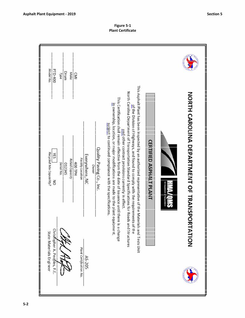
Asphalt Plant Equipment - 2019 Section 5
5-2
Figure 5-1
Plant Certificate

Section 5 Asphalt Plant Equipment - 2019
5-3
5.4 ASPHALT PLANT SPECIFICATION CHECKLIST
The following inspection checks are to be made and used frequently by both QA and QC Technicians at the asphalt
plant. In addition to performing the following checklist, the Quality Assurance personnel should periodically perform an
inspection of the QC operations. Frequent visits to the plant should be made.
ITEMS TO BE CHECKED:
GENERAL REQUIREMENTS FOR ALL PLANTS
1. Check to see if the plant is certified in accordance with specifications?
If so, document for QA records on QA-4 or diary.
2. Check the stockpiles for:
(a) gradation
(b) uniformity
(c) segregation
(d) contamination
(e) ample space or bulkheads between stockpiles
(f) availability of materials as specified on job mix formula
3. Check cold feeders for:
(a) separate bin for each material size to be used
(b) a separate bin provided for mineral filler, if required
(c) bins loaded in a manner such that materials will not be mixed
(d) all gates in workable condition
(e) synchronized proportioning system when two or more bins used
(f) vibrators on bins where needed in workable order
(g) all cold feeders equipped with “no-flow” sensors and in good operating condition
(h) cold feeders calibrated in accordance with the job mix formula and documented as required
4. Check dryer drum for:
(a) capability of continuously agitating aggregate
(b) thermometric instrument in discharge chute functioning properly
(c) automatic burner control functioning
(d) operation of Warm Mix water injection system
5. Check trucks for:
(a) the truck bodies are smooth and clean
(b) the body is washed down with an approved release agent and well drained before loading
(c) covers are being used on trucks and are of adequate size such that they will cover the load and prevent
the entrance of moisture or rapid loss of temperature
(d) proper loading ( three dumps at different locations within the bed of the truck )
(e) each truck body has a hole at least 3/8 inch in diameter on each side of the body six inches (6”) above
the floor to facilitate the checking of temperature
6. Check to see if a satisfactory truck access (sampling platform) is provided
7. Check truck scales for:
(a) truck scales accurately calibrated and certified by Department of Agriculture in accordance with
Article 106-7 of the Standard Specifications
(b) automatic weighing and recording equipment is operating properly, if used
(c) the Contractor's public weighmaster is properly licensed and current
(d) certified weigh tickets are being issued in accordance with Article 106-7
8. Check Field Laboratory and Testing Equipment for:
(a) The laboratory is certified as meeting the requirements of Article 609-5 of the Specifications
(b) All testing equipment is available and in good operating condition and properly calibrated
9. Have the proper field mix verification tests been performed in accordance with Article 609-3 of the Specifications and
this manual on the mix type being produced?

Asphalt Plant Equipment - 2019 Section 5
5-4
BATCH PLANT OPERATIONS
10. Check hot bins and screens for:
(a) screens and screen deck are in satisfactory condition
(b) screening system is capable of removing oversize material
(c) hot bin sampling devices are operational
(d) hot bin overflow chutes are functional so as to prevent spillage into other bins
(e) gates close tightly to prevent leakage
(f) no holes exist in bin partitions
11. Mineral Filler, if needed, is introduced into the mix as specifications require
12. Check weigh box or hopper for:
(a) capability of weighing each size aggregate automatically
(b) gates closing tightly to prevent spillage into mixer
(c) Form QC-2 (scale check) completed for aggregate scales and asphalt scales and posted at plant site, and
a copy provided to the Pavement Specialist
13. Check mixer for:
(a) no leaks occur in mixer box during mixing
(b) condition and clearance of mixer blades from fixed and moving parts adequate to assure complete
mixing and coating of aggregate
(c) timing device set and locked at desired mixing time
(d) batches are being mixed at rated capacity of mixer
(e) required mixing time is being obtained after the asphalt starts being discharged into the pugmill
(f) the mix is of uniform appearance and temperature
14. Recycling Equipment, if applicable: ( RAP/RAS )
(a) is plant equipped to automatically weigh and proportion the reclaimed material according to the
job mix formula requirements?
(b) have weighing devices for reclaimed material been checked and calibrated to meet specification
tolerances?
DRYER-DRUM OPERATIONS
15. Check plant for:
(a) aggregate belt scales have been calibrated
(b) asphalt binder metering system has been calibrated
(c) aggregate moisture percentage has been determined and entered into control system
(d) asphalt binder specific gravity data from mix design or most recent load ticket been entered correctly
(e) vibratory scalping screen is functional
(f) aggregate and asphalt binder feed rates are automatically interlocked
16. Check asphalt binder system for:
(a) adequate circulation of asphalt binder and anti-strip additives
(b) silicone has been added for surface mixes
(c) anti-strip additive has been added in correct amounts at the terminal when required by the
job mix formula or either in-line blending to be done at plant
(d) totalizer flow meter properly installed and operating properly (If anti-strip additive introduced at
plant site).
(e) thermometer in binder feedline operating and temperature of asphalt binder is at mixing temperature
(f) no leaks in system occur in work area
(g) asphalt binder scales or meter are accurately calibrated
(h) form QC-2 (scale check) completed for aggregate weigh bridges, binder meters and anti- strip additive
meters with a copy provided to the Pavement Specialist
17. Check if automatic proportioning and mixing equipment (including anti-strip, WMA, or fiber additive equipment) is
operating properly and being used to produce mix
18. Recycling equipment, if applicable:
(a) is plant equipped to automatically weigh and proportion the reclaimed material according to the
job mix formula requirements?
(b) have weighing devices for reclaimed material been checked and calibrated to meet specification
tolerances with form QC-2 completed and furnished to the Pavement Specialist?

Section 5 Asphalt Plant Equipment - 2019
5-5
5.5 BATCH PLANT OPERATIONS AND COMPONENTS
Batch plants get their name from the fact that, during operation, they produce asphalt mix in batches, producing
one batch at a time, one after the other. The size of a batch varies according to the capacity of the plant's pugmill (the
mixing chamber where aggregate and binder are blended together). A minimum batch capacity of 3,000 lbs. is required. A
typical batch capacity is about 6,000 lbs.; however, this may be as great as 12,000 lbs.
Certain basic operations are common to all batch plants. They are:
• Aggregate storage and cold feeding.
• Aggregate drying and heating.
• Screening and storage of hot aggregates.
• Storage and heating of asphalt binder.
• Measuring and mixing of asphalt binder and aggregate.
• Loading of finished asphalt mix.
Figure 5-2 illustrates the major components of a typical asphalt batch plant. Each component or group of related
components is discussed in detail in sections that follow; however, an overview of the processes involved in plant operations
will help the technician to understand the functions and relationships of the various plant components.
Figure 5-2
Major Batch Plant Components
Cold (unheated) aggregates stored in the cold bins (1) are proportioned by cold-feed gates (2) on to a belt
conveyor or bucket elevator (3), which delivers the aggregates to the dryer (4), where they are dried and heated. The
baghouse (5) removes undesirable amounts of dust from the dryer exhaust. Remaining exhaust gases are eliminated
through the plant exhaust stack (6). The dried and heated aggregates are delivered by hot elevator (7) to the screening
unit (8) equipped with a scalping screen to remove any oversized material. This oversized material is deposited into a reject
chute (15) for disposal. The material is then sized into different sized fractions and deposited into separate hot bins (9) for
temporary storage. When needed, the heated aggregates are measured in controlled amounts into the weigh box (10).
The aggregates are then dumped into the mixing chamber or pugmill (11), along with the proper amount of mineral filler,
if needed, from mineral filler or baghouse fines storage (12). If the plant is capable of producing recycled mixes then a
RAP Bin and conveyor (16) is needed. Heated asphalt binder from the hot asphalt binder storage tank (13) is pumped into
the asphalt binder weigh bucket (14) which weighs the asphalt binder prior to delivering it to the mixing chamber or pugmill
where it is combined thoroughly with the aggregates, baghouse fines or mineral filler if used. From the mixing chamber
asphalt mix is deposited into waiting trucks or delivered into storage silos or surge bins (17). When anti-strip additives are
introduced at the plant site an additive storage tank (18) is required with a totalizing flowmeter (19), which is not capable
of being reset, mounted in the additive feed line just prior to introduction into the binder feed line.

Asphalt Plant Equipment - 2019 Section 5
5-6
5.6 DRUM-MIX PLANT OPERATIONS AND COMPONENTS
Drum mixing is a relatively simple process of producing asphalt mix. The mixing drum from which this type of plant
gets its name is very similar in appearance to a batch plant dryer drum. The difference between drum-mix plants and batch
plants is that, in the more conventional drum-mix plants the aggregate is not only dried and heated within the drum, but
also mixed with the asphalt binder. However, there are some more recent model drum mix plants that introduce the asphalt
binder outside the drum. The addition of a coater box, which is a pugmill type device, located at the discharge end of the
drum allows the asphalt binder to be added into the coater box instead of into the drum. Still other "double barrel" type
drum mix plants will add the asphalt binder between an inner and outer drum. The basic concept of all these types is the
same though -- a continuous mixing process as compared to the mixing of batches at batch plants. There are no gradation
screens, hot bins, or weigh hoppers in a drum-mix plant. Aggregate gradation is controlled at the cold feed and by the
gradations of the individual aggregates being used.
Figure 5-3
Basic Drum-Mix Plant
Drum mix plants vary in size and rated capacities from approximately 60 tons per hour up to several hundred tons
per hour. A minimum production capacity of 90 tons per hour for drum mix plants is required on all NCDOT construction
contracts.
Referring to Figure 5-3, the following is a brief, general description of the sequence of processes involved in a
typical drum-mix plant operation: Aggregates are deposited in the cold feed bins (1) from which they fed in exact
proportions cold feeders (2) across a vibratory scalping screen (3) on to a cold-feed conveyor (4). An automatic aggregate
weighing system or weigh bridges (5) monitors the amount of aggregate flowing into the drum mixer (6). The weighing
system is interlocked with the controls on the asphalt binder storage pump which draws asphalt binder from a storage tank
(7) and introduces it into either the drum, coater box, or between an inner and outer drum, where asphalt and aggregate
are thoroughly blended by a mixing action. A dust collection system baghouse (8) captures excess dust escaping from the
drum. From the drum, the asphalt concrete is transported by mix conveyor (9) to a surge bin or silo (10) from which it is
loaded into trucks and hauled to the paving site. All plant operations are monitored and controlled from instruments in the
control room. When anti-strip additives are introduced at the plant site an additive storage tank (11) is required with a
totalizing flowmeter (12), which is not capable of being reset, mounted in the additive feed line just prior to introduction
into the binder feed line.

Section 5 Asphalt Plant Equipment - 2019
5-7
5.7 INTRODUCTION OF ANTI-STRIP ADDITIVES AT BATCH PLANT OR DRUM PLANTS
Use an anti-strip additive in all asphalt mixes. It may be hydrated lime or a chemical additive or a combination of
both as needed to meet the retained strength requirements as specified in Table 610-3. When a chemical additive is used,
add at a rate of not less than 0.25% by weight of binder in the mix, or as approved by the Engineer. When hydrated lime is
used, add at a rate of not less than 1.0% by weight of the total dry aggregate. When anti-strip additives are required in
asphalt mix, the anti-strip may be either chemical or hydrated lime or a combination of both.
When a chemical additive is used, it shall be added to the asphalt binder prior to introduction to the aggregate.
Any chemical additive or particular concentration of chemical additive found to be harmful to the asphalt material or which
causes the performance grading of the original asphalt binder to be out of specifications for the grade required shall not be
used. When anti-strip additives are required the anti-strip shall be introduced and mixed into the asphalt binder at either
the supplier's terminal or at the asphalt plant site. In-line blending equipment shall be used at either location. When
hydrated lime is used, it shall conform to the requirements of ASTM C 977. Hydrated lime shall be added at a rate of not
less than 1.0 percent by weight of the total dry aggregate. When chemical anti-strip additive is to be added at the asphalt plant in lieu of at the terminal, equip the plant with
an in-line blending system capable of metering the additive within plus or minus 10 percent of the amount specified.
Interlock the metering device with the asphalt binder control equipment in such a manner as to automatically vary the
additive feed rate to maintain the required proportions and which will automatically indicate in the plant control room
when flow is obstructed or stops. Inject the additive into the asphalt binder feed line prior to introduction into the
aggregate. Equip the feed line with a blending device to thoroughly mix the additive with the asphalt binder prior to mixing
with the aggregate. Provide a system capable of being calibrated, checked, and monitored for accuracy and quantity of the
amount used. Anti-strip additives are required in all NCDOT asphalt mixes. The quantity of anti-strip additive to be added
will be based on the new or additional binder in the mix. Technicians should refer to the Job Mix Formula for the actual %
of anti-strip additive for each mix type being produced. The in-line blending system will be equipped with an in-line totalizing
flowmeter. The following are the guidelines for checking the totalizing flowmeters:
1. Totalizer Flowmeter is required if the chemical additive is introduced to the binder at the plant site.
2. Totalizer Flowmeter must be mounted in the additive feedline past the calibration bypass valve.
3. Totalizer Flowmeters must not be capable of being reset. Meter readings will be the accumulated total flow of
additive through the meter.
4. Totalizer Flowmeter is in addition to the calibration meter that is standard on additive systems.
5. Calibration Meters must be mounted in the additive feedline prior to the calibration bypass valve and as close to
the actual point of additive introduction into the feedline as practical.
6. Additive storage tanks should be capable of being checked for quantity used. Checked either with a calibrated
stick or a measuring gauge on the tank.
7. Additive storage tanks shall be equipped with a thermostatically controlled heating system capable of heating
and maintaining the additive tank, contents and distribution system at the additive supplier’s recommended
temperature for the type of additive being used.
8. Any metering system not fully meeting the above requirements may only be used with the approval of the
Engineer.
Note: Quality Control personnel are required to read the flowmeter prior to production, during production and at the end
of production and record the readings on forms QC-1 and QC-3 as per instructions in Section 12.
When hydrated lime is used as anti-strip additive, provide a separate bin or tank and feeder system to store and
proportion the lime into the aggregate in either dry or slurry form. Mix the lime and aggregate by pugmill or other approved
means to achieve a uniform lime coating of the aggregate before entering the drier. When the lime is added in dry form,
the aggregate shall contain at least 3% free moisture. The stockpiling of lime treated aggregate will not be permitted.
Control the lime feeder system by a proportioning device that is accurate to within ± 10% of the specified amount. Provide
a proportioning device with a convenient and accurate means of calibration and that is interlocked with the aggregate feed
or weigh system so as to maintain the correct proportion. Provide a flow indicator or sensor that is interlocked with the
plant controls such that production of the mixture will be interrupted if there is a stoppage or reduction of the lime feed.
5.8 INTRODUCTION OF ANTI-STRIP ADDITIVE AT BINDER SUPPLIER’S TERMINAL
The anti-strip shall be introduced and mixed into the asphalt binder at either the supplier's terminal or at the
asphalt plant site.

Asphalt Plant Equipment - 2019 Section 5
5-8
5.8.1 Introduction of Chemical Anti-Strip at the Binder Terminal
When the additive is introduced at the supplier's terminal, the additive shall be blended in-line for a minimum of
80% of the asphalt binder loading time. The asphalt binder delivery ticket shall show the rate, (or quantity), brand and
grade of the additive. The Contractor shall furnish the name of the supplier, shipping point and grade of the anti-strip
additive if blended at the plant site. The blending system shall be capable of being calibrated, checked, and monitored for
accuracy, and amount used. A thermostatically-controlled heating system capable of heating and maintaining the additive
tank’s contents and distribution system at the temperature recommended by the additive supplier for the type additive
being used is required. The frequency of calibration of the additive system at the plant site will be the same as for the
asphalt binder scales or asphalt binder meters, or as deemed necessary by the Engineer.
5.8.2 Introduction of Chemical Anti-Strip at the Asphalt Mix Plant via In-Line Interlocked Metering System
Equip the plant with an in-line blending system capable of metering the additive within plus or minus 10 percent
of the amount specified. Interlock the metering device with the asphalt binder control equipment in such a manner as to
automatically vary the additive feed rate to maintain the required proportions and which will automatically indicate in the
plant control room when flow is obstructed or stops. Inject the additive into the asphalt binder feed line prior to
introduction into the aggregate. Equip the feed line with a blending device to thoroughly mix the additive with the asphalt
binder prior to mixing with the aggregate. Provide a system capable of being calibrated, checked, and monitored for
accuracy and quantity of the amount used. The in-line blending system will be equipped with an in-line totalizing flowmeter.
The following are the guidelines for checking the totalizing flowmeters:
1. Totalizer Flowmeter must be mounted in the additive feedline past the calibration bypass valve.
2. Totalizer Flowmeters must not be capable of being reset. Meter readings will be the accumulated total flow of
additive through the meter.
3. Totalizer Flowmeter is in addition to the calibration meter that is standard on additive systems.
4. Calibration Meters must be mounted in the additive feedline prior to the calibration bypass valve and as close to
the actual point of additive introduction into the feedline as practical.
5. Additive storage tanks should be capable of being checked for quantity used. Checked either with a calibrated
stick or a measuring gauge on the tank.
6. Additive storage tanks shall be equipped with a thermostatically controlled heating system capable of heating
and maintaining the additive tank, contents and distribution system at the additive supplier’s recommended
temperature for the type of additive being used.
Note: Quality Control personnel are required to read the flowmeter prior to production, during production and at the end
of production and record the readings on forms QC-1 and QC-3 as per instructions in Section 12.
5.8.3 Introduction of Chemical Anti-Strip at the Asphalt Mix Plant via In-Line Batch-Metering System
When the additive is introduced at the asphalt mix plant by a batch-metering system, the additive shall be blended
in-line for a minimum of 80% of the asphalt binder unloading time. The anti-strip additive may be introduced at or before
the asphalt binder storage tank strainer and unload pump. This method shall achieve thorough mixing of the additive and
the asphalt binder during unload. The blending system shall be capable of being calibrated, checked, and monitored for
accuracy, and amount used. Use a thermostatically-controlled heating system capable of heating and maintaining the
additive tank’s contents and distribution system at the temperature recommended by the additive supplier. The frequency
of calibration of the additive system at the plant site will be the same as for the asphalt binder scales/meters or as deemed
necessary by the Engineer.
5.8.4 Introduction of Hydrated Lime as an Anti-Strip Additive
When hydrated lime is used as anti-strip additive, provide a separate bin or tank and feeder system to store and
proportion the lime into the aggregate in either dry or slurry form. Mix the lime and aggregate by pugmill or other approved
means to achieve a uniform lime coating of the aggregate before entering the drier. When the lime is added in dry form,
the aggregate shall contain at least 3% free moisture. The stockpiling of lime treated aggregate will not be permitted.
Control the lime feeder system by a proportioning device that is accurate to within ± 10% of the specified amount. Provide
a proportioning device with a convenient and accurate means of calibration and that is interlocked with the aggregate feed
or weigh system so as to maintain the correct proportion. Provide a flow indicator or sensor that is interlocked with the
plant controls such that production of the mixture will be interrupted if there is a stoppage or reduction of the lime feed.

Section 5 Asphalt Plant Equipment - 2019
5-9
5.9 WARM MIX ASPHALT (WMA) TECHNOLOGIES
Warm Mix Asphalt typically incorporates the use of an additive to allow a reduction in the temperatures at which
asphalt mixes are produced and placed. Thus, asphalt can be placed in cooler temperature conditions often found at night,
early and late in the paving season, and during changing weather conditions. An additional important benefit of the Warm
Mix Asphalt technology is the reduction in energy consumption. When Warm Mix Asphalt technologies are implemented,
the overall temperature of the mix is often reduced. This means less fuel required at the production plant to heat the
aggregates to the traditional hot mix asphalt (HMA) temperatures. With the decreased production temperature comes the
additional benefit of reduced emissions at the plant and during lay down. There are many known technologies that have
been developed and used to produce WMA. They include the following:
• Plant production with nozzles injecting water into the stream of hot asphalt binder causing it to foam the asphalt
inside the mixing drum. This foaming process allows for better coating of all the aggregate materials in the mix.
• The addition of a synthetic zeolite to create a foaming effect in the asphalt binder.
• The use of organic additives with a low molecular weight wax.
• The addition of a surfactant to reduce the surface tension of the asphalt to allow better coating at lower
temperatures without changing the viscosity of the asphalt binder.
An approved products listing of Warm Mix Asphalt (WMA) Technologies for use in North Carolina is available by contacting
the Asphalt Laboratory or at the following web link:
https://connect.ncdot.gov/resources/Materials/MaterialsResources/Warm%20Mix%20Asphalt%20Approved%20List.pdf
5.10 N.C. DEPARTMENT OF AGRICULTURE & CONSUMER SERVICES (NCDA & CS) SCALES CERTIFICATION
Scales used to weigh materials for payment shall be certified in accordance with rules and regulations set forth by
the Standards Division of the Department of Agriculture & Consumer Services (NCDA & CS) in accordance with the General
Statutes of North Carolina. These requirements apply to scales used to weigh asphalt mixes for pay purposes. These
procedures and regulations are outlined below. Note that the length of certification is generally one year. Satisfactory
evidence of certification will be a NCDA & CS sticker placed on the weighing equipment.
NCDA & CS Rules, Regulations and Procedures
1) Contractors, Subcontractors, and suppliers who utilize scales to weigh materials for payment shall have the scales
certified by the NCDA & CS in accordance with the rules and regulations set forth by that agency.
2) The NCDA & CS will certify, if appropriate, all existing scales during each calendar year. The effective period of this
certification is through December 31 of the following year. For example, any scale certification issued during a calendar
year will be effective through the end of the following calendar year.
3) The NCDA & CS will schedule and inspect all existing platform scales during their normal work schedule. The owners of
existing platform scales do not need to schedule NCDA & CS for a scale check.
4) On platform scales that have not been certified previously or platform scales that have been relocated, the owners of
the scales shall notify the Standards Division of NCDA & CS at least thirty days prior to commencement of any use. If the
thirty day notification cannot be met, the owners of the scales may engage a scale company licensed by the NCDA & CS
to test and certify the scales. The certification by the licensed scale company will be acceptable until the NCDA & CS
inspects and certifies the platform scales.
5) On all other type scales utilized to weigh materials for pay purposes, such as batch plant scales or load cells on silos, the
scales owner shall notify the NCDA & CS at least two weeks prior to the actual scales check. NCDA & CS prefers that
these type scales be checked during the months of January thru March and will make every effort to check those during
that time frame. This type of scale check will not be conducted by NCDA & CS personnel but must be monitored by them
for certification. Either the Contractor or a certified scales company may perform this check, but in either case, it must
be done under the supervision of NCDA & CS personnel in order for the scales to be certified.
6) No additional compensation or time extension will be allowed for use of a scale company.
7) All scales check should be conducted either prior to any use of new or relocated scales, or prior to the expiration of
certification of existing scales.

Asphalt Plant Equipment - 2019 Section 5
5-10
Note: Section 6 continues in detail with asphalt plant equipment and procedures for both the batch and drum
plants. It also outlines procedures and frequency for calibrating the following:
1) cold feed calibrations and different methods (batch and drum plants)
2) asphalt scales, weigh bridges and meter systems (batch and drum plants)
3) computing percentages and weights for hot bins at a batch plant
4) aggregate scale and weigh bridge frequencies (batch and drum plants)
5) anti-strip additive meters system calibration (if anti-strip is introduced at plant site)

Section 6 Asphalt Plant Operations - 2019
6-1
SECTION 6
ASPHALT PLANT OPERATIONS
6.1 GENERAL ASPHALT PLANT REQUIREMENTS
6.1.1 Asphalt Binder Storage and Handling
There are numerous grades of asphalt binder, asphalt emulsions, and other asphalt materials used in highway
construction. For asphalt mix production, it is the responsibility of both the QC & QA technicians to insure that the proper
grade of asphalt binder as shown on the job mix formula is being used. It is also the responsibility of the technicians to see that
the asphalt binder is handled and stored properly. Asphalt binder used for NCDOT work must be certified or tested prior to
use (See Delivery and Acceptance of Asphalt Materials in Section 2).
The QC technician should check to see that the asphalt binder is properly stored and protected. Before production is
started, the QC & QA technicians should determine that the asphalt binder to be used is the grade and from the source as that
stated on the job mix formula. The technicians should also determine if the asphalt binder has been certified or tested. If there
is no evidence of the asphalt binder being certified or tested, the QC technician should immediately notify the Pavement
Specialist.
The asphalt binder storage capacity at the plant must be sufficient to allow uniform plant operation. Where more
than one grade of asphalt binder is required for a project, at least one tank will be needed for each grade or the tank must be
completely emptied before a different grade is added. Different grades of binders shall not be mixed.
Asphalt binder storage tanks must be capable of being measured so that the amount of material remaining in the tank
can be determined at any time. They also must be heated to keep the asphalt binder fluid enough to move through the delivery
and return lines. Heating is done either electrically or by circulating hot oil through coils in the tank. Regardless of the heating
method used, an open flame must never come in direct contact with the tank or its contents. The asphalt binder shall not be
heated to a temperature in excess of the supplier's recommendation while stored or when being used in production of the mix
at the plant. Where circulating hot oil is used, the oil level in the reservoir of the heating unit should be checked frequently. A
drop in the level could indicate leakage of the hot oil into the tank, leakage which results in contamination of the asphalt binder.
All transfer lines, pumps and weigh buckets also must have heating coils or jackets so that the asphalt binder will remain fluid
enough to pump. One or more thermometers must be placed in the asphalt binder feed line to ensure control of the asphalt
binder temperature, as it is being introduced into the mixer or drum.
The asphalt binder tanks must be equipped with a circulation system capable of uniformly dispersing and mixing
additives throughout the total quantity of asphalt binder in the tank. Required additives must be added sufficiently in advance
of production so as to insure that they are thoroughly distributed throughout the asphalt binder. See Section 5 for more specific
requirements for in-line blending of anti-strip additives. Adequate pumps must be furnished so that asphalt binder can
be unloaded from tankers and still continue to operate the plant. A sampling valve or a spigot must be installed in the circulating
system or tank to allow sampling of the asphalt binder. When sampling from the circulating system, exercise extreme care, as
pressure in the lines may cause the hot asphalt binder to splatter.
6.1.2 Asphalt Mix Temperature Requirements
The temperature of the binder and aggregates must be adequate to allow for proper coating of the aggregate with
the binder and sufficient mixing action to produce a uniform asphalt mixture. The completed asphalt mixture must be within
a desired range to allow for proper placement and compaction without having damaged the binder in the mix.
The mixing temperature at the asphalt plant will be established on the job mix formula. The mixing temperature will
be different depending on the grade of asphalt binder specified in Table 610-3. The JMF mix temperature shall be within the
ranges shown in Table 610-1 unless otherwise approved:
TABLE 610-1
MIXING TEMPERATURE AT THE ASPHALT PLANT
Binder Grade JMF Mix Temperature
PG 58-28; PG 64-22 250 - 290° F
PG 76-22 300 - 325° F
When RAS is used, the JMF mix temperature shall be established at 275°F or higher.
These are normal mixing temperatures; however, certain circumstances may call for a higher or lower mixing
temperature. Plant and Roadway Technicians should always refer to the most current Job Mix Formula for the correct mixing

Asphalt Plant Operations - 2019 Section 6
6-2
temperature. The temperature of all mixes when checked in the truck at the asphalt plant shall be within ±±±± 25° F of the JMF
temperature. The temperature of the mixture, when discharged from the mixer, shall not exceed 350° F.
6.2 AGGREGATE STORAGE
Good stockpiling and storage procedures are crucial to the production of top-quality asphalt mix. When stockpiled
properly, aggregates retain their proper gradation. When stockpiled poorly, aggregate particles segregate (separate by size),
and gradation varies at different levels within the stockpile. All handling degrades (breaks down) individual aggregate particles
to some extent, and, where different-sized aggregate particles are involved, may cause particle segregation. Therefore,
handling should be kept to a minimum to prevent degradation and segregation that could make the aggregate unsuitable for
use. The technician should be aware of the effect of various stockpiling and handling practices on aggregate gradation and
should encourage good practices at all times.
Aggregates must be handled and stored in a manner that will minimize segregation and avoid contamination. The
aggregates should be stockpiled in the vicinity of the plant on firm ground that drains well and has been cleared of vegetation
and prepared in such a manner as to protect the aggregates from contamination. Stockpiles must be separated to prevent
intermingling. This can be accomplished by positive separation of the stockpiles (space), by using adequate bulkheads, by the
use of silos, or other means. If bulkheads are used, they should extend to the full depth of the stockpiles and must be strong
enough to withstand the pressures that will be exerted under operating conditions.
Stockpiles should be constructed in layers, rather than in cone shaped piles. Individual truckloads should be spotted
close together over the entire stockpile surface. When stockpiling with a crane, each bucketful should be deposited adjacent
to another, over the entire area, so that the layers will be of uniform thickness. When constructing, maintaining, or removing
aggregates from coarse aggregate stockpiles, one should be careful to minimize degradation caused by the equipment.
Operating on top of the stockpiles with either rubber-tired or tracked equipment should be minimized.
6.3 AGGREGATE COLD FEED SYSTEM
The flow of aggregate through an asphalt plant begins at the cold feed bins. The cold feed system (Fig. 6-1) for both
batch and drum mix plants consists of a series of cold bins (usually 3 to 5) with gates and feeders mounted under the bins and
the entire unit positioned over a collector conveyor belt. There must be a separate cold feed bin for each aggregate size used
in a particular mix type. The usual setup will be four cold bins. Separate feeder bins must be used when RAP / RAS is being
incorporated into the mixture.
Each cold bin should be large enough to hold an adequate supply of aggregate. When the bins are mounted together,
there should be a baffle between adjacent bins that will prevent one bin from overflowing into the adjacent bin, causing
variations in the gradation and properties of the mix. Each bin will be equipped with an adjustable gate opening and a feeder
belt to draw aggregate out of each bin at a controlled rate. The aggregate from each feeder is then deposited onto a collector
conveyor and then fed into the dryer. The gate openings and feeder belt speeds for the various aggregate feeders must be
synchronized and calibrated to deliver the proper amount of each material required by the JMF for each mix. Section 6.4
discusses how to calibrate the cold feed blend ratio being fed into the plant based on specific gate openings and belt speeds to
determine conformance with the aggregate blend on the JMF.
Figure 6-1
Three-Bin Cold Feeder and Belt

Section 6 Asphalt Plant Operations - 2019
6-3
There are several types of cold feeders used on plants, including:
1. Continuous Belt Feeder (Variable Speed Belt), Fig. 6-2
2. Vibratory Feeder, Fig. 6-3
3. Gravity Flow Feeder, Fig. 6-4
Generally, continuous belt and vibratory feeders are best for accurately metering of both coarse and fine aggregates
and most commonly used on plants today. A continuous belt feeder system in conjunction with a scalping screen is the type
normally used to provide the necessary control for drum mix plants. For a uniform output from the asphalt plant, input must
be accurately measured and controlled. Cold feeders must be synchronized so that a change in the feed rate of one is
proportional to the feed rate of all others. Each bin must be equipped with a no-flow sensor that will alert the plant operator
and/or shut down the plant if aggregate flow stops or becomes restricted. The importance of feeding the required amounts of
each size aggregate into the dryer at the correct rate of flow cannot be over-emphasized. This is doubly important when the
plant is a drum mixer, since there is no re-grading of the aggregates by a screening unit as at a batch plant.
Figure 6-2
Continuous Belt Feeder (Variable Speed Belt)
Figure 6-3
Electromagnetic Vibratory Feeder
Figure 6-4
Gravity Flow Feeder

Asphalt Plant Operations - 2019 Section 6
6-4
6.4 CALIBRATION OF COLD FEED BLEND RATIOS
The production and construction of a high quality asphalt pavement meeting the mix design requirements and with
the required density begins with the cold feeders at the asphalt plant. The job mix formula is based on a mix design, which was
developed based on a specific blend or ratio of coarse aggregate, fine aggregate, and RAP/RAS (when used) with individual
specific gravities and gradations. During mix design, these materials are combined in such proportions that will result in a
combination gradation and asphalt binder percentage that meets the design criteria for that particular type of mix. This blend
ratio must be maintained during production if the design criteria are to remain valid. Excessive deviation from this blend may
change the optimum asphalt binder percentage, result in a low stability mix, deficient or excessive air void content, a different
mix specific gravity or other changes. It is for these reasons that the blend ratio shown on the job mix formula must be closely
maintained at the asphalt plant.
The cold feeder aggregate blend ratio must be calibrated in accordance with Table 6-1 and as directed by the Engineer.
While this calibration is the responsibility of the Contractor, the QA technician must be aware of the methods and procedures
used and, be able to check or verify the calibration. Approval of mix verification by the Pavement Specialist will not be granted
without satisfactory evidence of the cold feed blend calibration.
There are instances where the gradation of one or more of the individual aggregates and/or RAP/RAS may have
significantly changed from that used in the initial mix design. This may make it impossible to meet the combined mix gradation
if the blend ratio is still maintained. While it is usually best to maintain the blend ratio and adjust the gradation target values,
there may be situations where it is better to change the aggregate blend ratio. This is especially true when two or more “same”
source aggregates are being used. In these situations, QC personnel may make per aggregate cold feed blend changes of ±10%
or less from the JMF target without prior QA approval. A cold feed blend change in excess of ±10% can only be authorized by
the Asphalt Laboratory. In most cases, a blend change in excess of ±10% will cause a new mix design to be considered.
Calibration of the Cold Feeders can be done by various methods. Any method is satisfactory provided the blend ratio
can be determined with reasonable accuracy. Reasonable accuracy is normally considered to be within ±5% of the JMF target
for each aggregate and RAP/RAS components. This tolerance should not be confused with the allowable adjustments covered
in Section 7.4. This ±5% tolerance is only for calibration evaluation purposes and is not applicable to allowable blend
adjustments. Whichever method is used, aggregate and RAP/RAS samples must be actually weighed in order to determine the
cold feed blend percentages. Some of the more commonly used methods of calibration are listed below:
• Pan Method: A pan or shallow container is passed beneath each operating feeder unit to obtain a sample of
material that will be weighed and then converted to a percentage of the total aggregate weight (including
RAP/RAS) being furnished.
• Length-of-Belt Method: A sample of each material being used (including RAP/RAS) is taken from a constant belt
length, weighed, and then converted to a percentage of the total aggregate weight being furnished.
• Weigh Bridge Method: Each material being used (including RAP/RAS) is run across the aggregate weigh bridge
and into a truck at a normal production rate for a fixed amount of time. Individual bin feed rates are then
converted to a percentage of the total weight being furnished.
• Manufacturer's Method: Most manufacturers’ plant manuals contain specific procedures for cold feed
calibrations. These are acceptable methods, provided the aggregates are actually weighed in some manner
during the process.
While these are some of the more commonly used calibration methods, there may be other acceptable methods. As
mentioned before, any method is satisfactory provided the blend ratio can be accurately determined by actually weighing the
aggregate or RAP/RAS samples. While acceptable accuracy is generally within ±5% of the JMF target for each aggregate and
RAP/RAS component, the blend ratio at a drum mix plant probably needs to be maintained more accurately than this since
there is no secondary screening unit as in a batch plant. Again, this tolerance is for blend calibration purposes only and is not
applicable to allowable blend adjustments. The percentage of RAP/RAS shown on the JMF may not be adjusted except with
the specific approval of the Asphalt Mix Design Engineer. Figures 6-5 and 6-6 are examples of a length-of-belt method of
calibration and a JMF comparison. While this is the example used in this manual, it in no way implies that this is a better or
more accurate method than the others listed above.

Section 6 Asphalt Plant Operations - 2019
6-5
Figure 6-5 Cold Feed Blend Calibration Example (Length-of-Belt Method)
Given a total of 50.0 lbs. of aggregate (A+B+C+D) taken from a cross-section of cold feed belt, determine the percentage of
each aggregate being used:
No. 67 Stone = 5 - 0 = 5 lbs. 5 ÷ 50 = 10%
No. 78M Stone = 35 - 5 = 30 lbs. 30 ÷ 50 = 60%
D. Scrgs = 45 - 35 = 10 lbs. 10 ÷ 50 = 20%
C. Sand = 50 - 45 = 5 lbs. 5 ÷ 50 = 10%
Total = 50 lbs. Total = 100%
Note: Sample across the entire cross-section of belt for a minimum of two (2) feet.
Each section removed after each feeder must be the same length for all feeders.
Figure 6-6
NCDOT JMF – Compare Cold Feed Calibrations
Compare Cold Feed Calibration Results
With JMF Blend Percentages
#67
A
78M
B
D. Scrgs.
C
C. Sand
D
50 lb 45 lb 35 lb 5 lb

Asphalt Plant Operations - 2019 Section 6
6-6
Table 6-1
Plant Calibration Frequencies
Device/Control Minimum Frequency*
Cold Feeder Aggregate Blend Ratio 12 months
Aggregate Scales/Weigh Bridges 12 months
Asphalt Binder Scales 12 months
Asphalt Binder Meters 12 months
Anti-Strip Meter System 12 months
*NOTES: 1) Perform Calibrations at the minimum frequency above and anytime the Plant has been idle for 90 days or
more.
2) A new calibration of all proportioning devices or plant controls shall be performed after any malfunction and
all necessary repairs of the equipment have been completed OR after any device/control is moved or
exchanged.
3) All original calibration records shall be kept on site at the plant for audit by the Engineer.
6.5 BATCH PLANT OPERATIONS
6.5.1 The Dryer
The aggregates are delivered from the cold feeder to the dryer. The dryer accomplishes two things: (1) it removes
moisture from the aggregates and (2) it raises the aggregate temperature to the desired level. The component parts of the
dryer are: (1) a revolving cylinder usually from 3 to 10 feet in diameter and from 20 to 40 feet long; (2) a burner which is either
gas or oiled fired; and (3) a fan, which may be considered part of the dust collector system, but its primary function is to provide
the draft air for combustion in the dryer. The dryer is equipped with longitudinal troughs or channels, called lifting flights,
which lift the aggregate and drop it in veils through the burner flame and hot gases.
The slope of the drum, its speed of rotation, diameter, length, and the arrangement and number of flights control the
length of time required for the aggregate to pass through the dryer. The aggregate then passes to the hot elevator through a
discharge chute near the burner end of the dryer.
The dryer will have an automatic burner control device with an approved thermometric instrument located in the
aggregate discharge chute to actuate the automatic burner control. The purpose of the automatic burner control is to insure
a uniform mix temperature and to prevent overheating of the aggregate, which can cause damage to the asphalt during mixing.
Fluctuating mix temperatures often result in poor laydown and compaction results. Uniform density at the required degree of
compaction cannot be achieved when the mix temperature varies from one batch or load to the next.
Figure 6-7
Dryer

Section 6 Asphalt Plant Operations - 2019
6-7
6.5.2 Screening Unit
The screening unit (see Fig. 6-8) includes a set of several different sized vibrating screens. The first in the series of
screens is a scalping screen which rejects and carries off oversized aggregates. This is followed by one or two intermediate-
sized screens, decreasing in size from top to bottom. At the bottom of the stack is a fine screen, occasionally referred to as a
"sand" screen (see Figure 6-9). The screens serve to separate the aggregates into specific sizes. To perform this function
properly, the total screen area must be large enough to handle the total amount of feed delivered. Here again, the screens
must be clean and in good condition. The capacity of the screens must be in balance with the capacity of the dryer and the
capacity of the pugmill. When too much material is fed to the screens or the screen openings are plugged, many particles,
which should pass through, ride over the screens and drop into a bin designated for larger size particles. Similarly, when screens
are worn or torn, resulting in enlarged openings and holes, oversized material will go into bins intended for smaller-sized
aggregate. Any misdirection of a finer aggregate into a bin intended to contain the next larger size fraction is called "carry-
over". Excessive carry-over can add to the amount of fine aggregate in the total mix, thus increasing the surface area to be
covered with asphalt binder. If the amount of carry-over is unknown or if it fluctuates, particularly in the No. 2 bin, it can
seriously affect the mix design in both gradation and asphalt binder content. Excessive carry-over can be detected by a sieve
analysis of the contents of the individual hot bins and must be corrected immediately by cleaning the screens or reducing the
quantity of material coming from the cold feed, or both. Some carry-over is to be expected and permitted in normal screening
operations, provided it remains relatively uniform.
Figure 6-8
Screening Unit
The No. 2 bin (intermediate fine aggregate) is the critical bin for carry-over. This is the bin that will receive the finest
aggregate in carry-over and which will affect the asphalt binder demand of the mix the most. Typically, the carry-over in the
No. 2 bin should not exceed 10 percent. Running a sample of the No. 2 bin material over a No. 8 (2.36mm) sieve will indicate
the amount of carry-over. To prevent excessive carry-over, daily visual inspection of the screens for cleanliness and overall
condition is recommended, preferably before starting each day's operation. When conditions warrant, the screens shall be
cleaned or replaced.
6.5.3 Hot Bins
Hot bins are used to temporarily store the heated and screened aggregates in the various sizes required. Each bin is
an individual compartment or a segment of a larger compartment divided by partitions (see Fig. 6-9). Properly sized hot bin
installation should be large enough to hold sufficient material of each size when the mixer is operating at full capacity. The bin
partitions must be tight, free from holes, and high enough to prevent intermingling of the aggregates. Each hot bin shall be
equipped with an overflow pipe to prevent aggregate from backing up into other bins. The overflow pipes shall be checked
frequently to make sure they are functioning and thus prevent contamination by intermingling sizes from adjacent bins. The
bottom of each bin is fitted with a discharge gate which shall close tightly so that no material is allowed to leak into the weigh
hopper.
All hot bins are to be equipped with a device to permit sampling of the aggregate from each bin. Samples of aggregates
from these bins may be taken from "gates" or "windows" in the sides of the bins, or by diverting the flow of aggregates from
the bins into the sampling container. It is essential that the sampling devices or methods be such that representative samples
of the materials in the hot bins can be obtained. Gradations of the samples from the different bins will then be analyzed to
determine the hot bin pulls, as discussed later.

Asphalt Plant Operations - 2019 Section 6
6-8
Figure 6-9
Typical Batch Plant Setup for Screens and Hot Bins
6.5.4 Aggregate Weigh Hopper
Aggregates are released from the hot bins directly into the weigh hopper, generally beginning with the largest size
aggregate and progressing down to the finest size, where the mineral filler usually is used, sandwiched between the larger
aggregates. The amount from each bin is determined by the batch size and the proportions or percentages required to be
blended. Determination of hot bin percentages and hot bin pull weights will be discussed later in this section.
The weigh hopper is suspended from a scale beam and the amounts of aggregate are weighed cumulatively. Before
withdrawal starts, there should always be sufficient materials in the hot bins for a complete batch. If a bin is near depletion or
is running over, chances are that an adjustment in the cold feed rates or hot bin pulls are required.
6.5.5 Asphalt Binder Bucket or Meter
Asphalt binder may be weighed in a special bucket, or it may be measured by a meter for each batch. When weighed
into a batch, asphalt binder is pumped into a bucket of known weight and weighed on a scale.
When metering devices are used, a volumetric measurement is made. The volume of asphalt binder changes with
temperature. Some asphalt binder meters have built-in temperature-compensating devices that correct the flow of asphalt
binder when changes in temperature occur. The volume of asphalt binder pumped between two meter readings may be
weighed as a means of calibrating the meter.
6.5.6 The Mixer Unit (Pugmill)
After proportioning, the aggregate and binder are introduced into the pugmill for mixing. Batch plants are equipped
with a pugmill mixer, which consists of twin shafts equipped with paddles for mixing the ingredients into a homogeneous mass
(see Fig. 6-10). Main parts are: the paddle tips, paddle shanks, spray bar, liners, shafts, discharge gate and heated jacket.
Efficient mixing is dependent upon the number, shape, and condition of the paddle tips, speed of the mixing shafts, length of
mixing time, temperature of the material, quantity of materials in the mixer, and specifically the clearance between the paddle
tips and liner plates. All batch plants shall have a mixer with a rated capacity of not less than 3,000 lbs.
Close attention should be given, through visual inspection, to the uniformity and coating of the mix. Excessive
clearance between paddle tips and mixer liners, broken, worn or missing paddle tips and the batch size are factors which can
contribute to a lack of uniformity and coating of the mixture. Batch sizes should be determined by the rated capacity of the
mixer. The rated capacity of the pugmill mixer will be indicated on the plant certification. Underfilling or overfilling should not
be allowed. The mixers of batch mix plants and continuous mix plants are essentially of the same design, except for the
variations in arrangement of the paddle tips. In the batch-mix mixer, the materials are dumped into the center of the mixer
and the paddles are arranged to give an end-to-center mixing or a run-around (“figure-eight”) mixing pattern. The material is
held in the mixer the required mixing time and then discharged through the discharge gate into the transporting vehicles. The
mixer shall be equipped with an automatic timing device to automatically regulate the dry-mixing and wet-mixing periods.
Hot Elevator
Hot bin #1 Hot bin #2 Hot bin #3 Hot bin #4
Gate Gate Gate Gate
Reject Chute
2 ” (50mm) or 2 ¼” (57mm) Square opening 1” (25mm) or 1¼” (32mm) Square opening
3/4” (19mm) Square opening # 6 Slotted (3.35mm)

Section 6 Asphalt Plant Operations - 2019
6-9
Figure 6-10
Pugmill Mixer for a Batch Plant
6.5.7 Automatic Control of Proportioning and Mixing
All plants shall have fully automated controls for proportioning and mixing. A fully automatic system is defined as one
such that once mix proportions and timers are set and the plant operation is started, it will automatically complete the
proportioning and mixing cycle without further effort of the plant operator or until a shortage of material or some extraordinary
event causes the plant itself to halt the operation.
The mixer must be equipped with an interlocking timing device, capable of being set at intervals of five seconds or
less, to control the operations during the mixing cycle. The mixing time will be established by the plant operator or the QC
technician. The mixing time should be long enough to get a uniform distribution of aggregate sizes and a uniform coating of
asphalt binder on all aggregate particles; however, excessive mixing should not occur due to the hardening effect of the asphalt
binder film on the aggregate by exposure to air and heat.
6.5.8 Calibration of Batch Plant Asphalt Scales, Weigh Bridges, and Meters
A certified Level I or Level II plant technician shall be present during this calibration. A Level II Technician signs the
QC-2 Form certifying the accuracy of the scales check when completed. Separate sets of scales are used to weigh asphalt
binder, aggregates, RAP and RAS (if applicable), being used in the mix. The Contractor is required to check the calibration of
these aggregate scales, asphalt binder scales, and weigh bridges (recycled mixes) in accordance with Table 6-1 and as directed
by the Engineer. All plant scales shall be accurate to 0.5 percent of the anticipated scale settings that may be required. The
Contractor shall have on hand not less than ten 50 lb. weights for testing the plant scales. The procedures and documentation
of this calibration are described below:
(A) AGGREGATE SCALES & WEIGH BRIDGES:
The aggregate scales are checked as follows: Scales are first checked with the weigh hopper empty
to be sure they show zero. Then ten 50 lb. standard weights are either placed on or attached to the aggregate
weigh hopper and the scales reading is read and recorded. This will be the increment check. Care should be
taken in evenly distributing these weights in order to prevent scale misalignment. The weights are then
removed and the same amount of aggregate is drawn from the hot bins and deposited into the weigh hopper
to replace the standard weights. The ten weights are again placed on or attached to the weigh hopper and
another scale’s reading is taken and recorded. This would be the 1000 lb. increment check. This procedure
is repeated at 500 lb. intervals until the total weight checked is slightly more than the pounds of aggregate
that will be used in each batch of mix. At anticipated scale settings, the scales must be within 0.5 % accuracy.
If not, it is the Contractor's responsibility to make the necessary adjustments or have scales repaired by a
qualified scales technician. A recheck of the scales would then be made to ensure their accuracy.
During normal operations, aggregate scales should be monitored to be sure they zero correctly
during weighing operations and that they show no signs of binding or dragging which would cause erroneous
readings. Some common causes of scale malfunction are: build-up of asphalt binder, dust, corrosion or
dulling of the scales' knife edges, or aggregates lodging in the scale supports. Belt scales (weigh bridges) are
utilized at some batch plants to monitor the RAP material percentage used in recycled mixes. When used,
these belt scales will be checked using the same procedure for checking belt scales on a drum mix plant (See
Section 6.6.3 for this procedure).

Asphalt Plant Operations - 2019 Section 6
6-10
(B) ASPHALT BINDER SCALES:
The asphalt binder scales are calibrated in nearly the same manner as the aggregate scales, but only
one weighing operation is required. The 50 lb. standard weights are placed on or attached to the asphalt
binder bucket one at a time, and readings are recorded as each weight is added. This is continued until the
combined weight is slightly in excess of the pounds of asphalt binder required per batch of paving mixture.
Asphalt binder scales, if in true adjustment, should indicate the same value as the total of the standard
weights used, and must be within the required 0.5 % accuracy at the anticipated scale setting. If the weighing
scales error exceeds the tolerance permitted by specifications, plant operations should not be started until
the scales are adjusted or repaired by a qualified scale technician. This corrective measure is the Contractor's
responsibility. During normal operations, the tare weight of the empty bucket should be watched carefully
to see that the bucket is drained completely and to compensate for any asphalt binder and dust clinging to
it. The asphalt binder bucket should be tared at the beginning of each day and checked after the first few
loads are discharged. Quite often, asphalt binder accumulates on the side and bottom and reduces the
weight of asphalt binder actually used in the mix.
(C) ASPHALT BINDER METERS:
Asphalt binder meters are volume displacement mechanisms, and when used they should be
checked for accuracy. The metering system should also be within 0.5 % accuracy. Since asphalt binder
content is usually expressed as a percent by weight, a correlation between meter readings and weight should
be established. A simple method to determine the correlation is to read the meter, pump a quantity of
asphalt binder into a tared container, and then read the meter again. The weight of asphalt binder divided
by the difference in meter readings determines the weight of asphalt binder pumped per division. For a
more detailed explanation of checking an asphalt binder metering system, see Section 6.6. The viscosity and
unit weight of the asphalt binder change with a change in temperature. When the temperature is increased
the viscosity decreases. The unit weight decreases about 1 % for each increment of increase in temperature
of 28° F. Pumping efficiency may be affected by a change in temperature, and it may be desirable to calibrate
the pump over a range of asphalt binder temperatures. Volumes and viscosities can be determined later for
calibration and plotting purposes if necessary. Some asphalt binder meters have built-in temperature-
compensating devices that correct the flow of asphalt binder when temperature changes occur. When a
meter without a temperature-compensating device is used, it is necessary to adjust the delivery setting for
each change in asphalt binder temperature. The technician should refer to the plant manual for additional
details.
(D) ANTI-STRIP METERING SYSTEM:
The anti-strip metering system shall be capable of being calibrated, checked, and monitored for
accuracy, and amount used. If the anti-strip additive is introduced into the binder at the plant site, When an
In-Line Interlocked Metering System is used, a calibration flowmeter is mounted in the anti-strip additive
feed line near the additive storage tank. This meter is to insure that the additive pump is operating properly
and the correct amount of additive is being uniformly introduced into the binder at all times. The metering
device will be interlocked with the asphalt binder control equipment in such a manner as to automatically
vary the additive feed rate to maintain the required proportions and which will automatically indicate in the
plant control room when the additive feed rate is obstructed or stops. This meter should be checked for
accuracy at both batch and drum plants and should be within ±10% of the amount of additive specified on
the JMF.
NOTE: This calibration flowmeter should not be confused with the Totalizer Flowmeter that is also required
on the additive feed line if additive is introduced to the binder at the plant. See Section 5.7 for
details on the requirements for the totalizer flowmeter.
Since the additive is introduced at minor dosages, it is adequate to pump off only a small quantity
to check the meter. The procedure is as follows: Check and record the current meter reading. Pump off 4-
5 gallons of additive (based on the meter reading) through the by-pass valve into a tared container.
Determine the additive weight by weighing contents of tared container on scales accurate to at least the
nearest pound. Calculate the actual gallons pumped off by dividing this weight by the pounds per gallon
weight of the additive. The pounds per gallon weight is determined by multiplying 8.33 times the specific
gravity of the additive. The specific gravity of the additive can normally be found on the additive delivery
ticket or by contacting the supplier. The gallons shown to have been pumped off by the meter reading should

Section 6 Asphalt Plant Operations - 2019
6-11
be within ±10% of the actual gallons. If not, the meter must be adjusted and this procedure repeated until
the required tolerance is met.
(E) DOCUMENTATION:
A plant scales calibration Form QC-2 (see Section 12) and/or certification by the Department of
Agriculture or a certified scale company will suffice for either the initial check or for a periodic check,
provided the date of the certification is within the timeframe noted in Table 6-1. A single scales check may
and should serve for several different projects if the check was conducted within the above noted time.
Form QC-2 (see Section 12) should be submitted to the Pavement Specialist at the completion of each scales
check. As noted, the QC Technician should post a copy of Form QC-2 in the QC Laboratory when the scales
are actually calibrated.
6.5.9 Setting of Batch Weights
Normally it is the Contractor's responsibility to calibrate the hot bins; however, the QA technician should observe and
be aware of the procedures used to arrive at an aggregate combination that meets the job-mix formula. To produce the desired
asphalt mix; it is necessary to pull a certain amount of aggregate from each hot bin. The amount that is pulled from each bin
is dependent upon what the Job Mix Formula calls for and what each hot bin contains (the gradation); which means the content
of each bin must be analyzed.
The first step is to start running the plant, the cold feed, the dryer and the screens. After the plant has settled down
so that the material in the bins is representative of the proportions established at the cold gates, a sample of aggregate is taken
from each bin.
(A) HOT BIN SAMPLING:
This method describes a procedure for obtaining representative aggregate samples from the
asphalt plant hot bins. An approved sampling device is used that will retain a representative sample of
aggregates when passed through a veil of material flowing out of the bin chute. The device must be of a
dimension so that it will extend slightly more than the distance from the outside edge of the predominantly
fine material to the outside edge of the predominantly coarse material as the device enters the stream of
flowing aggregates. A shovel is not acceptable.
In the flow of material over the plant screens, finer particles fall to the near side of the bins and
coarser particles fall to the far side, particularly in the No. 1 bins (See Fig. 6-11). When material is drawn
from the bin by opening a gate at the bottom, the stream consists predominantly of fine material at one
edge and coarse material at the other. This condition is critical in the No. 1 (fine) bin, since the asphalt binder
demand is influenced heavily by the material from this bin. Therefore, the relative position of the sampling
device in the stream determines whether the sample will be composed of the fine portion, the coarse
portion, or will be an accurate representation of the total material in the bin (see Fig. 6-11). Each
compartment shall be equipped with adequate and convenient devices to provide for sampling. This means
that the plant must be constructed to either (a) enable a sampling device to be inserted and used effectively,
(b) to have an approved gate, window or slide under each bin for diverting the flow of aggregates from the
bins into the sampling device, or (c) to contain an automatic bin sampling device.
Figure 6-11
Segregation of Aggregates in Hot Bins (Note Segregation Inside Each Bin)

Asphalt Plant Operations - 2019 Section 6
6-12
The sampling procedure is as follows: Verify that the containers and sampling device are clean. Pass the
sampling device through the veil of material as it flows from the bin. The sampling device must be inserted
under the stream of material in such a way that the device simultaneously collects the predominantly fine
material at the other edge (see Fig. 6-12). The sampling device will be withdrawn before it overflows and
the contents deposited in a clean container. This procedure will be repeated for each bin to be analyzed.
Figure 6-12
Correct Use of Sampling Device
(B) SIEVE ANALYSIS OF EACH BIN:
A sieve analysis will be run on each sample taken from the hot bins. This is done as soon as the
samples cool down to the point they can be handled. The equipment and test procedures are those specified
for running sieve analysis of coarse and fine aggregates according to NCDOT-T-27. The information is
recorded on the standard form B-75-2 (see Fig. 6-13).
(C) DETERMINING HOT BIN PERCENTAGES:
Once the gradation of material in each hot bin is determined, the percentage to be pulled from each
bin to meet the job mix formula gradation can be calculated. This is best done by use of a trial and error
method. In determining proper calibration of the hot-bin feeds, the job-mix formula is the starting point. It
is necessary to determine what percentage of each size of the aggregate in the hot bin should be
incorporated into the mix in order to meet the job mix formula gradation requirements. It should be stressed
that there can be numerous sets of hot bin pull percentages that are correct. Any combination of bin
materials that will meet the job mix formula gradations, with the Specification tolerances applied will be
acceptable and satisfactory. The purpose of this trial and error Form B-75-2 procedure is to arrive at a
starting point for plant production to ensure that the mix will be reasonably close to our job mix formula.
First the gradation of material in each of the hot bins is determined. Aggregate proportions are then
estimated as follows. The raw material passing the 2.36 mm sieve and the 0.075 mm sieve is used as a starting
point. Of the three hot bins used for this I19.0C mix, bin No. 1 carries most of the minus 2.36 mm and minus
0.075 mm material. This will generally be true in all batch plants since the screen over the No. 1 bin is of
such size to normally control the mix gradation from the 2.36 mm sieve down through the 0.075 mm sieve.
This being the case, the 2.36 mm sieve through 0.075 mm sieve gradations in the asphalt mix can be
controlled by the percentage of material pulled from the No. 1 hot bin.
Beginning with the 2.36 mm, the job mix formula requires that 52% pass this sieve. Note that there
is 93 % passing the 2.36 mm sieve in hot bin No. 1. Since this 93 % represents the majority of minus 2.36mm
material in all three hot bins, the 52 % required in the mix can be controlled from this 93 %. The 52 is divided
by the 93 for a percentage result of 56 % that is to be pulled from the No. 1 bin. In other words, what percent
of the No. 1 bin minus 2.36 mm material is needed to give the desired percent passing the 2.36 mm on the
job mix formula. The 0.075 mm sieve is now checked in the same manner, as was the 2.36 mm above. The
job mix formula requires that 4.8 % pass the 0.075 mm sieve. The No. 1 bin has 8.9 % minus 0.075 mm
material. The 4.8 is divided by the 8.9 for a result of 54 %. Either the 56 % (arrived at by use of 2.36 mm) or
the 54 % (arrived at by use of 0.075 mm) will meet the job mix formula requirements. The example in Figure
6-14 uses 55 % out of hot bin No. 1.
As the hot bin containing the finest graded material had certain characteristics that enabled us to
control certain portions of our mix gradation, so does the hot bin containing the coarsest graded material.

Section 6 Asphalt Plant Operations - 2019
6-13
This characteristic is different, or opposite, from that in the fine bin in that this is large stone, which is
generally retained on the majority of sieves instead of passing most sieves. This retainage characteristic is
used to estimate the percentage to be pulled from the bin containing the coarsest material.

Asphalt Plant Operations - 2019 Section 6
6-14
Figure 6-13
Aggregate Blending Worksheet (Form B-75-2)
For
m B
-75-
2
Pro
ject
Num
ber
8.11
2233
44H
ot B
inX
Sto
ckpi
leD
ate
5/27
/201
7Ti
me
12:3
0C
ount
yC
old
Fee
dO
ther
Con
trac
tor
Qua
lity
Asp
halt
Pa
ving
Co.
Type
Mix
I 19
.0 C
JMF
No.
17-0
004-
151
Pla
nt L
ocat
ion
Eve
ryw
here
N
C.
Mat
eria
lM
.F.
Com
bina
tion
Sou
rce
Hot
Bin
1H
ot B
in 2
Hot
Bin
3of
Mat
eria
ls
Sam
ple
Wt.
H
ot B
in,
Sto
ckpi
le
Dry
Wt.
850.
011
03.0
1215
.0
or C
old
Fee
d
% M
oist
.1
23
4R
apM
.F.
Ble
ndJM
F
Acc
. W
t.%
Ret
.%
Pas
sA
cc.
Wt.
% R
et.
% P
ass
Acc
. W
t.%
Ret
.%
Pas
sA
cc.
Wt.
% R
et.
% P
ass
% P
ass
%%
%%
%%
Sie
ve S
ize
55.0
15.0
30.0
100.
0
50.0
mm
100.
010
0.0
100.
055
.015
.030
.0
100
100
37.5
mm
100.
010
0.0
100.
055
.015
.030
.0
100
100
25.0
mm
100.
010
0.0
100.
055
.015
.030
.0
100
100
19.0
mm
100.
010
0.0
100.
055
.015
.030
.0
100
100
12.5
mm
100.
010
0.0
142.
011
.788
.355
.015
.026
.5
9695
9.50
mm
100.
010
0.0
440.
036
.263
.855
.015
.019
.1
8989
4.75
mm
18.0
2.0
98.0
125.
011
.388
.710
50.0
86.4
13.6
53.9
13.3
4.1
71
70
2.36
mm
59.5
7.0
93.0
960.
087
.013
.012
00.0
98.8
1.2
51.2
1.9
0.4
53
52
1.18
mm
290.
034
.165
.910
30.0
93.4
6.6
1205
.099
.20.
836
.21.
00.
2
3737
0.60
0 m
m42
5.0
50.0
50.0
1090
.098
.81.
212
08.0
99.4
0.6
27.5
0.2
0.2
28
28
0.30
0 m
m54
0.0
63.5
36.5
1092
.099
.01.
012
13.0
99.8
0.2
20.1
0.1
0.0
20
20
0.15
0 m
m70
0.0
82.4
17.6
1100
.099
.70.
312
13.0
99.8
0.2
9.7
0.0
0.0
10
10
0.07
5 m
m77
4.0
91.1
8.9
1101
.099
.80.
212
14.0
99.9
0.1
4.9
0.03
0.02
5.
04.
8
Pan
850.
011
30.0
1215
.0To
tal M
oist
ure
Ble
nd:
Test
Per
form
ed b
y:I. B. DeM
an
Gra
datio
n
Ag
gre
gat
e B
len
din
g W
ork
shee
t
Rap
Bin
Rap

Section 6 Asphalt Plant Operations - 2019
6-15
The example in Figure 6-13 uses three hot bins to make this I19.0C mix, with No. 3 bin containing
the coarsest graded material. (The hot bin farthest to the right from the plant's hot elevator will always
contain the coarsest material.) Keep in mind that the No. 1 hot bin is already set at 55 % which controls the
2.36 mm through 0.075 mm sieves; therefore, we need not be concerned about these sieves any more. The
concern now is for the sieves above, or larger than, the 2.36 mm.
In order to select a controlling sieve which determines the amount to pull out of the No. 3 bin, the
gradation for all sieves above the 2.36 mm in all three bins need to be compared. The first sieve above the
2.36 mm that differs drastically in gradation, from that same sieve's gradation in the Nos. 1 and 2 bins, will
be the controlling sieve. The 4.75 mm is the first sieve above the 2.36 mm. The 4.75 mm gradation is 98%
in the No. 1 bin, 89% in the No. 2 bin, and 13.6% in the No. 3 bin. The 4.75 mm sieve gradation is very much
different in bin No. 3 from that in Bin Nos. 1 and 2; therefore, this will be our controlling sieve. These
gradations show that there is basically no plus 4.75 mm material in bin Nos. 1 and 2, with bin No. 3 containing
86.4% plus 4.75 mm; therefore, bin No. 3 is the only bin from which the plus 4.75 mm material in the mix
can be controlled. The job mix formula requires that 70 % pass the 4.75 mm sieve, which means that 30 %
would be retained on that sieve. Since the No. 3 bin is basically the only hot bin with plus 4.75 mm material,
30 % would be pulled from this bin in order to have 30 % plus 4.75 mm in the mix.
The remaining bin (No. 2 in our example) will be set at the difference between 100 % and the total
percent of bin Nos. 1 and 2. This would be 100 minus 85 (55 plus 30) or 15 % to be pulled out of the No. 2
bin. At times only two hot bins will be used. In those cases, the No. 1 hot bin will be set as outlined previously
and the balance percentage will be pulled from the No. 2 bin. Also, there will be times when four hot bins
will be used for 19.0 mm and 25.0 mm mixes. In these cases, the Nos. 1 and 4 hot bins will be set as previously
outlined and the balance percentage should be split 1/3 out of the No. 2 bin and 2/3 of the balance out of
the No. 3 bin. This 1/3:2/3 split comes from experience and has proven to normally meet the job mix formula
needs.
After deciding on a set of hot bin percentages, it is necessary to verify that these percentages will
meet the job mix formula requirements. This is done by blending the hot bin materials together, on paper,
at the percentages decided upon. Following this procedure through in our example, it will be seen that the
55-15-30 percent combination of hot bin materials will produce a mix gradation that is very close to the job
mix formula.
(D) CALCULATING BATCH WEIGHTS
After determining the proportions required for each hot bin, we can calculate the weight of asphalt binder
and the amount of aggregate to be pulled from each bin to produce a single batch of asphalt mix. First, we select
a batch size, which will be mainly dependent upon the pugmill capacity of the asphalt plant. Assume that we have
a 4,000 lbs. capacity pugmill.
Summarize the information we have available:
Batch size: 4,000 lbs.
% Binder: 5.8% (given on JMF)
Bin #1 (% to be pulled): 55%
Bin #2 (% to be pulled): 15%
Bin #3 (% to be pulled): 30%
From this information, the weight of asphalt binder in each batch can be calculated by multiplying the
batch weight by the percentage of asphalt binder in each batch: 4000 lbs. x 0.058 (5.8%)= 232 lbs.
The total weight of aggregates in each batch is determined by subtracting the weight of the asphalt binder
from the total batch weight: 4000 lbs. – 232 lbs. = 3768 lbs.
From Trial and Error
Method in
Section 6.5.9(C)

Asphalt Plant Operations - 2019 Section 6
6-16
Knowing the total weight of all aggregates needed for a batch of asphalt mix, along with the estimated hot
bin percentages, allows calculation of the weights of aggregate to be pulled from the bins. This calculation is shown
below.
Bin
No.
Proportion
Percent
Aggregate
Weight (lbs)
Required
Weight (lbs)
1 55 % X 3768 = 2073
2 15 % X 3768 = 565
3 30 % X 3768 = 1130
Total Aggregate Weight = 3768
(E) SETTING THE BATCH WEIGHTS
(1) AGGREGATE SCALES:
From the hot bins the aggregates are withdrawn for deposit into a weigh hopper. The weigh
hopper is suspended from scale beams and weighs accumulatively the amounts of aggregate
entering it (see Fig. 6-14).
These settings should be marked on the scale and used until adjustments are required (see Fig. 6-15).
Bin Batch Sequence 1, 2, 3: Hot Bin #1 = 2073 lbs.
Hot Bin #2 = Hot Bin #1 2073 lbs. +
Hot Bin #2 565 lbs. = 2637 lbs.
Hot Bin #3 = Hot Bin #1 2073 lbs. +
Hot Bin #2 565 lbs. +
Hot Bin #3 1130 lbs. = 3768 lbs.
Figure 6-15
Asphalt Plant Scale Settings
(2) ASPHALT BINDER SCALES:
From the weigh hopper, the aggregates are deposited into the plant's pugmill (mixing
chamber), where they are blended with the proper proportion of asphalt binder. In a typical
plant system, asphalt binder is weighed separately in a weigh bucket before being introduced
into the pugmill (see Fig. 6-16). This weight is set on a separate asphalt binder scale from the
aggregate scales. From the previous computations, our asphalt binder scales setting would be
232 lbs. (see Fig. 6-15).
0 0
Aggregate
Scales
Binder
Scales
3768 lbs.
2638 lbs.
2073 lbs. 232 lbs.

Section 6 Asphalt Plant Operations - 2019
6-17
Figure 6-16
Typical Asphalt Binder Measuring and Delivery System
(3) AUTOMATIC PLANTS:
The batch weights for the mix are normally set on the control panel of an automatic plant by
various formula setting devices. The three methods used on most automatic plants are as follows:
(a) Preset Dial Type: Each dial is set to the individual weight to be pulled from the
corresponding hot bin. A separate dial is also used for the asphalt binder.
(b) Batch Plug: A batch plug consists of several potentiometers; each set for the individual
component weight and enclosed in a case about half the size of a cigarette pack. A
number of these can be stored at the plant for various mixes.
(c) Central Processor Unit: Computer System capable of storing different mix types, printing
batch weights and controlling most plant operations.
6.6 DRUM MIX PLANT OPERATIONS
Drum mixing is a relatively simple process of producing asphalt mix. The mixing drum from which this type of plant
gets its name is very similar in appearance to a batch plant dryer drum. The difference between drum-mix plants and batch
plants is that, in most drum-mix plants the aggregate is not only dried and heated within the drum, but also mixed with the
asphalt binder. However, there are some more recent model drum mix plants that introduce the asphalt binder outside the
drum. The addition of a coater box, which is a pugmill type device, located at the discharge end of the drum allows the asphalt
binder to be added into the coater box instead of into the drum. Still other "double barrel" type drum mix plants will add the
asphalt binder between an inner and outer drum. The basic concept of all these types is the same though -- a continuous mixing
process as compared to the mixing of batches at batch plants. There are no gradation screens, hot bins, weigh hoppers or
pugmills in a drum-mix plant. Aggregate gradation is controlled at the cold feed.
6.6.1 Cold Feed System
Since the drum mix plant does not incorporate a gradation screening unit, the aggregate must be accurately
proportioned prior to entry into the mixing drum. Mix gradation and uniformity are entirely dependent on the cold-feed
system. The plant must be equipped with provisions to conveniently obtain representative samples of the full flow of material
from each cold feed and the total cold feed for calibration purposes. Calibration of the cold feeds to determine compliance
with the job mix formula is essentially the same as for batch plants. The technician should refer to Section 6.4 for these
procedures and see Table 6.1 for frequency of calibration.
Each feeder shall be equipped with an automatic device which activates a warning alarm and/or flasher light when any
bin becomes empty or when aggregate flow becomes restricted. The automatic device shall be interlocked into the plant
control system so as to automatically stop production if normal aggregate flow is not resumed within 60 seconds. Each feeding
system shall be so constructed that samples can be readily obtained.

Asphalt Plant Operations - 2019 Section 6
6-18
6.6.2 Vibratory Scalping Screen
A vibratory screening system capable of removing all oversize materials for the particular mix being produced shall be
provided prior to entry of the aggregate into the dryer-drum mixer. Normally, a screen size just slightly larger than the
maximum aggregate size for the type mix being produced is satisfactory. It is also desirable that the scalping screen unit be
located just after the material leaves the cold feed bins and prior to the material passing over the weigh bridge of the aggregate
weighing system. This serves to uniformly distribute the material on the belt and results in less fluctuation of the aggregate
feed rate data being conveyed to the plant control blending system.
6.6.3 Weight Measurement of Aggregate and RAP/RAS
Drum-mix plants require a continuous weighing system on the cold feed conveyor belts (including RAP/RAS conveyor
belts). In-line belt weighing devices, also called weigh bridges (Fig. 6-17) are continuous belt-weighing devices used for this
purpose. Combined aggregates or RAP/RAS passing over the conveyor belt are continuously weighed and a readout (in the
control room) indicates the weight of the flow over the scale at any given instant. No material should ever be diverted from
the conveyor belt after it passes the belt weigh bridge during actual production.
Figure 6-17 shows one of the conveyor idlers (designated the weigh idler) of the belt weigh bridge which is mounted
on a pivoted scale carriage. As the loaded belt passes over this idler, the weight is read in tons and/or tons per hour and a
reading displayed at the control console in the control trailer. This reading is normally corrected to account for moisture in the
aggregate (since dry-aggregate data is used to establish the required percentage of asphalt binder) and is a key reading in
monitoring plant operations. The in-line belt weigh bridge is usually located midway between the head and tail pulley of the
cold feed belt conveyor. This location tends to lessen variations in reading caused by impact loading, roll-back of aggregate or
changes in belt tension. A check of this device should be performed to ensure this accuracy at a frequency in accordance with
Table 6-1 and as directed by the Engineer. The device must be accurate within ±0.5 % at normal production rate.
Figure 6-17
Weigh Bridge
There are several various methods for checking these weigh bridges. Any method that will verify that the actual weight
passing across the weigh bridge as compared to the plant's digital readout will be satisfactory. Some of these methods are
briefly described next. These methods apply to and are acceptable for either virgin aggregate weigh bridges or RAP/RAS weigh
bridges. Before running either method, it is suggested that at least four (4) tons of one size aggregate be passed over the cold
feed conveyor belt and into a truck by means of a diversion chute. This quantity can then be dumped back onto the stockpile.
This precaution insures proper seating of the conveyor belt on the rollers and insures better accuracy. If this precaution is not
taken, the first test may give misleading results.
If the plant controls are equipped with a readout that gives actual weight (tons, not tons per hour) crossing the weigh
bridge, this check is as follows. First, set the plant's moisture compensator to zero and then zero out the belt scales. Next, run
approximately 15 tons of clean coarse aggregate for aggregate weigh bridges or a minimum of 10 tons for RAP and RAS weigh
bridges across the appropriate weigh bridge at normal production rate, and check the readout weight by use of a certified set
of scales. A coarse aggregate is preferable due to less chance of loss of fines during the weighing process, less moisture in the
material, and ease of handling as compared to finer materials. Means should be provided for diverting the aggregate into trucks,
or other containers. This is normally done by use of a diversion chute located at the end of the cold feed conveyor belt. The
quantity of test material will be run across the weigh bridge, through this diversion chute into a container, and then weighed
on an approved set of scales. The net weight will then be determined by subtracting the container weight from this gross

Section 6 Asphalt Plant Operations - 2019
6-19
weight. This net weight is then compared with the weight reading displayed in the plant control console. The readout should
compare within ± 0.5% of this net weight.
The plant may be equipped with a weigh bridge digital readout that only gives a rate in tons per hour. In this case, the
above procedure can generally be used but the actual weight will be converted to tons per hour. When making these checks,
it is very important that the plant be operated at normal production rate and this rate be uniformly maintained during the test.
As above, approximately 15 tons of clean coarse aggregate for virgin aggregate bins or 10 tons for RAP or RAS bins will be run
across the weigh bridge, through a diversion chute into a container, weighed, and a net weight determined. The difference
being that this is a timed test to be performed over some measured period of time. Time the material from its first crossing
the weigh bridge until the last material clears the weighbridge. The conversion to tons per hour is made by use of the following
formula:
���� ����⁄ = ����� ��������������(���. )�, ��� × ��� ��������(� ��. )
This figure is compared to the weigh bridge tons per hour shown on the readout. The readout must be within the ±
0.5% accuracy of the computed rate for either aggregate scales or RAP/RAS weigh bridges. Any necessary adjustments are made
in the electronics of the weigh bridge scale to compensate for the difference between the actual weight or tons per hour and
the digital readout. This adjustment is the Contractor's responsibility.
In drum-mix plants the aggregate is weighed before drying. Since the undried material may contain an appreciable
amount of moisture that can influence the aggregate's weight, an accurate measurement of aggregate moisture content is
important. From this measurement, adjustments can be made to the automatic asphalt binder metering system to ensure that
the amount of asphalt binder delivered to the drum is proper for the amount of aggregate minus its moisture content. The
technician should monitor the moisture content of the cold feed aggregate before beginning each day's operation and again
about the middle of the day, and the Contractor should adjust the moisture control equipment accordingly. If the moisture
content is believed to vary during the day, it should be checked more frequently. The moisture content may be determined
manually or electronically. A minimum of one moisture test per normal day's operation shall be performed by the plant
technician. See Section 7 for moisture test procedures. Provisions must be made for electronically correcting wet aggregate
weight readings to dry aggregate weight readings in the plant control system.
6.6.4 Asphalt Binder Meter System
Most drum-mixers are typically equipped with a device (Fig. 6-18) to add asphalt binder to the aggregate inside the
drum mixer. Some more recent model drum mix plants may be equipped to add the asphalt binder to the aggregate outside
the drum-mixer into a coater box, which is a pugmill type device.
Still other "double barrel" type drum plants will add the asphalt binder between an inner and outer drum. Either of
these will utilize an asphalt binder metering and delivery system which is a continuous mechanical proportioning system
interlocked with the aggregate weigh system to ensure the exact asphalt binder content of the mix. The weight of aggregate
going into the mixer, as measured by the weigh belt, is the basis of determining the quantity of asphalt binder delivered into
the drum or coater box, whichever is applicable.
Figure 6-18
Zones in Drum Mixer

Asphalt Plant Operations - 2019 Section 6
6-20
Most metering systems measure the volume (gallons) of asphalt binder being delivered by use of a volumetric
flowmeter. This volume must be converted to a weight rate of flow. Since the volume and weight are temperature dependent,
the plant control system must include a means to allow for temperature and specific gravity variations in asphalt binders. The
system must also have a temperature indicating device in the asphalt binder feed line. Procedures for making these
adjustments are usually included in the manufacturer’s plant operations manual.
Some drum mix plants are equipped with mass flowmeters that measure the mass of asphalt binder being delivered
instead of volume. These normally read out in a weight (instead of a volume) and, are not temperature and/or specific gravity
dependent.
The proportioning of asphalt binder is accomplished by establishing the necessary rate of asphalt binder delivery to
match the aggregate delivery rate in tons of dry aggregate per hour. The asphalt binder delivery rate is automatically increased
or decreased proportionately according to the corrected dry weight measurement of aggregate passing over the belt scale. The
rate of asphalt binder delivery is normally indicated in tons per hour on a rate meter on the control panel.
Means must be provided for checking the accuracy of the asphalt binder metering system. This check should be
performed at a frequency in accordance with Table 6-1 and as directed by the Engineer and should check within ±0.5 percent
accuracy.
Most drum-mixer plants are equipped with a by-pass valve system which will allow the asphalt binder to be pumped
through the flowmeter and into a container, instead of into the drum-mixer. By means of this by-pass system, a minimum of
500 gallons (or the appropriate quantity as recommended by the manufacturer) will be pumped off into a container. Due to
the quantity to be pumped off, this container will normally be either an asphalt distributor tanker or a supply tanker. This
container will need to have been previously weighed empty, in order to obtain the net weight of the pumped-off asphalt binder.
These weights should be made by use of a certified set of scales of sufficient capacity. The net weight of the asphalt binder
should be compared to the number of gallons shown pumped through the flowmeter, if a volumetric flowmeter is being used,
or compared to the weight shown if a mass flowmeter is being used. If a mass flowmeter is being checked, a direct weight to
weight comparison is made and no conversion is necessary. If a volumetric flowmeter is being checked, a conversion of either
pounds to gallons, or gallons to pounds, will have to be made in order to make the necessary comparison. This conversion can
be made by use of one of the following formulas:
������� = ������(�����. )(�. )× ! ����"#�$ � $���% �&@��℉
������ = ������� ×(�. ) × ! ����"#�$ � $���% �&@��℉
The specific gravity at 60°F should be given on the asphalt binder delivery ticket. The above conversion formulas are
useable only if the drum-mixer plant is equipped with systems that automatically compensate for varying asphalt binder
temperatures and specific gravities. It is very important to be sure these compensating systems are operating correctly before
checking the metering system. Most manufacturers’ manuals contain instructions for checking to see if these systems are
functioning properly.
The plant manual should always be consulted prior to the meter check for the manufacturer's recommended
procedures. This is important because some plant meter readouts show weights, some show gallons (liters) @ 60°F, and others
show liters (gallons) @ the actual binder temperature. The plant manual will always give the correct method of calibration and
conversion.
The flowmeter readout should check within ± 0.5% accuracy. Any necessary adjustments to be made to the metering
system are the Contractor's responsibility. Use form QC-2 (see Section 12) for documentation of this meter check.
The plant control read-out will show binder tons per hour being added to the mix. This read-out figure is calculated by the
plant control computer system utilizing the aggregate weigh bridge weights and the JMF % binder. This read-out should be
mathematically checked occasionally to be sure that the binder quantity is being calculated correctly. The following formula
should be used for this calculation:
)�*! ���� = )�*+�&,�������� - ./0��1�� − ./0��
3

Section 6 Asphalt Plant Operations - 2019
6-21
EXAMPLE CALCULATION:
Given: JMFPb= 6.2% (from JMF)
TPHDryAggregate = 160.0 (from Aggregate Weigh Bridge)
)�*! ���� = 1��.� - �. �
1�� − �. �3 = 1��.�(�. ����C���)
)�*! ���� = 1�.�����/���� This calculated TPH binder number should be within approximately 8% -10% (not tons per hour) of the readout. If the
plant is equipped with an additive metering system it should be calibrated at the same time the binder meter is calibrated. This
system should be accurate within ± 10% of amount specified. A similar process to the binder meter calibration will be followed
except that only a minimum of 5 gallons must be pumped off and weighed on calibrated scales of sufficient capacity.
6.6.5 Anti-Strip Additive Meter System
If the anti-strip additive is introduced into the binder at a drum mix plant, the additive meter system shall be
calibrated at a frequency in accordance with Table 6-1 and as directed by the Engineer and using the procedures in
Section 6.5.8.
6.6.6 Documentation
Drum plant weigh bridges / asphalt binder meters calibration Form QC-2 and/or certification by the Department of
Agriculture or a certified scale company will suffice for either the initial check or for a periodic check, provided the date of the
certification is within the time frame noted. A single scales check may and should serve for several different projects if the
check was conducted within the above noted time. Form QC-2 (see Section 12) should be submitted to the Pavement Specialist
at the completion of each scales check. As noted, the QC Technician should post a copy of Form QC-2 in the QC Laboratory
once the scales are actually calibrated.
6.6.7 Drum-Mixer Dryer
The heart of the drum-mix plant is the drum dryer itself (see Fig. 6-18). The dryer is similar in design and construction
to a conventional rotary dryer, except that most drum dryers utilize the parallel flow principle as opposed to the counter flow
principle used in conventional batch plants. The burner is mounted at the high end of the drum where the cold proportioned
aggregates are introduced. By using this approach, the hottest gases and flame are at the charging end of the drum. When
the asphalt binder is introduced further down the drum, it is protected from the excessive harmful effects of the burner flame
by the evaporating moisture on the aggregate. The exception to this is the newer model double barrel drum mix plants which
have the burner located on the lower end of the drum with the aggregate flow being toward the flame. This is because the
inner drum of this type plant serves the purpose of a drying chamber only and not that of a mixing chamber.
Some more recent model drum mix plants have been modified from the more conventional method, to methods that
will further protect the asphalt binder from excessive heat. The addition of a coater box at the discharge end of the drum and
the double-barrel drum mix plants both serve this purpose. The asphalt binder may be added into the coater box or between
the inner and outer drums; both being removed from direct flame exposure. The mix temperature is monitored on all type
drum plants by a thermometric device in the dryer discharge chute, which automatically activates the burner controls, and
therefore, controls the mix temperature. Dryer drum mixers shall have a rated capacity of at least 90 tons per hour when
producing a finished mixture at 300°F with removal of 5% moisture from the combined aggregate.
6.6.8 Surge-Storage Bins (Silos)
In a drum-mix operation, which produces a continuous flow of fresh asphalt mix, it is necessary to have a surge silo
for temporary storage of the material and for controlled loading of trucks. A weigh system may be connected to the holding
bin of the silo to monitor the amount of material loaded into each truck. Weight measurements are normally recorded by the
weigh system control panel, located in the control van or trailer.
Insulated silos or bins can store hot asphalt mix up to twelve (12) hours with no significant loss of heat or quality.
Capacities range as high as several hundred tons. Non-insulated storage structures are usually quite small and can store hot
mix only for short periods of time. Storage silos work well if certain precautions are followed, but they can cause segregation
of the mix if not used properly. It is good practice to use baffle plates, a batching hopper, a rotating chute, or similar devices
at the discharge end of the conveyor used to load the silo. These devices help to prevent the mix from coning and segregating

Asphalt Plant Operations - 2019 Section 6
6-22
as it drops into the silo. It is also recommended to keep the silo at least one-third full to avoid segregation as the silo empties
and to help to keep the mix hot.
Hot asphalt mix is dumped into the top of the bin and falls vertically into the structure. The bin must be designed so
that segregation of the mix is held to a minimum. The subsequent loading of trucks should be made with a minimum of three
dumps (see Figure 6-19 below). Three-dump loading as illustrated below greatly reduces the risks of segregation. Frequent
visual checks of the mix must be made by the QC Technician to make certain segregation has not occurred during the charging
of the bin and/or during loading into trucks. Coarse mixes must be watched closely since they are more subject to segregation.
Sample of the mix for testing purposes will be taken directly from the truck body in accordance with procedures outlined in
Section 7. Figure 6-19
Proper 3-Dump Loading of Truck
6.7 SEGREGATION OF ASPHALT MIXTURES
Segregation refers to a condition in asphalt in which there is non-uniform distribution of the various aggregate sizes
across the mat to the point where the mix no longer conforms to the specified job mix formula. Segregation is the tendency
of larger particles to separate from a mass of particles of different sizes under certain conditions. Segregation may be brought
about by the methods of mixing, storing, transporting, and handling the mix wherein there is a condition created that favors
non-random distribution of the aggregate sizes. Segregation problems are most often associated with drum mix plants. There
is, however, nothing to indicate that drum mix plants themselves are more prone to segregation problems than batch plants.
Segregation in asphalt pavements is more closely associated with surge-storage systems, which are most often used with drum
mix plants. The previous Section 6.6.8 explains the uses of these surge-storage systems, inherit segregation problems, and
some possible solutions.
Coarse graded mixes, such as the 25.0 mm Base mixes, are naturally more prone to segregate due to their stone
content, low asphalt binder content, and possible gap-grading. Finer graded mixes, such as the 9.5 mm surface mixes, do not
tend to have severe segregation problems for the opposite reasons of those noted with coarse graded mixes.
Segregation can originate at virtually any point in the process of asphalt production. It can get its start in the mix
design, in the aggregate stockpile, in the cold-feed bin, in the batch plant hot bin, in the drum mixer, in the drag-slat conveyor,
or in the surge-storage bin. In some cases, segregation doesn't start until the truck is being loaded out. The earlier segregation
begins during the process, the worse the problem tends to be due to more movement of the mix in completing the process.
Whenever segregation does occur, all of these areas should be closely monitored for their extent of contribution to the
problem.
The solution to segregation problems usually lies within several of these problem areas. Modifications in the mix
design may be needed; improper handling of the aggregates may need to be addressed; modifications to the plant, drag-slat
conveyor, and/or the surge-storage bin may be necessary; and the handling and movement of the mix through the surge-
storage bin and into the truck. It's most important to remember that for whatever the reason and at whatever the location
segregation begins, after it does, any unrestricted movement, especially down slope movement, will compound the problem
drastically. Because of this, down slope movement of the mix should be kept to a minimum throughout the asphalt process.
Reference should be made to the segregation diagnostic charts in the Appendix for possible solutions to various types of
segregation problems.

Section 6 Asphalt Plant Operations - 2019
6-23
6.8 SCALES AND PUBLIC WEIGHMASTER (ARTICLE 106-7)
Specifications for weighing asphalt materials, which are to be paid for on a ton basis, can be found in Article 106-7 of
the Standard Specifications. This Article requires that any scales, which are to be used to determine the weight for payment
purposes, shall be certified by the North Carolina Department of Agriculture and Consumer Services. This may include platform
scales and/or the plant aggregate and asphalt binder scales, depending upon which scales are being used by the Contractor's
public weighmaster to issue the weigh ticket. See Section 5.9 for specific details of the NCDA & CS certification requirements.
Requirements for automatic weighing, recording and printing of tickets are listed under Article 106-7. It should be noted that
this Article also requires that the JMF No. be recorded on each asphalt weigh ticket. Also included in Article 106-7 are provisions
for checking the scales by re-weighing a truck load of material on another set of approved platform scales.
It is the Resident Engineer’s and Pavement Specialist’s responsibility to assure that the Contractor is meeting the
requirements of Article 106-7 before any weigh tickets are issued. The requirements of this Article or approval of the weighing
equipment is not covered by the plant certification. Weigh tickets provide essential records for the control of project
operations, quality, and quantity of mix delivered. Although different systems are used by various agencies, certain items
related to tickets remain generally the same from project to project. Weigh tickets numbered consecutively are generally
issued at the asphalt plant. They must state the project number, the origin of the load, time loaded, the temperature and
weight of the load, the truck number, the type of mix, the JMF Number, Plant Certification Number and location (station
number) where the mix was placed. It will also list the weight and roadway temperature of the mixture. See Section 10.1.3,
the Project Special Provisions, and the Construction Manual for detailed requirements for asphalt weigh tickets.
6.9 HAULING OF ASPHALT MIXTURES
The QC and QA technicians must inspect truck bodies in which the mix is to be hauled to be sure that they comply with
Article 610-7 of the Standard Specifications and Section 9.5.1(c). The truck body should be inspected to make sure that the
bed has been lightly coated with an approved release agent to prevent the mixture from adhering to the bed. After the bed is
coated, any excess solution must be adequately drained before any mix is allowed to be loaded. Excess solution can be
extremely detrimental to mixture in which it comes in contact. Fuel Oil and Kerosene shall not be used. For an approved list
of truck release agents, use the Approved Products List website:
https://apps.ncdot.gov/vendor/approvedproducts/Default.aspx
The mixing temperature at the asphalt plant will be established on the job mix formula. See Section 6.1 for the normal
mixing temperatures. Plant and Roadway Technicians should always refer to the most current Job Mix Formula for the correct
mixing temperature. The temperature of all mixes when checked in the truck at the asphalt plant shall be within ±±±± 25° F of the
JMF temperature. The temperature of the mix immediately prior to discharge from the hauling vehicle at the roadway shall
be within ±±±± 25° F of the JMF temperature.
The mix should be observed frequently and the temperature checked at regular intervals and recorded. The
Contractor shall provide a platform near the truck loading area from which the mix may be observed and from which the
samples of the mix may be secured, as well as the temperature of the mix determined. Cover each load of mixture with a solid,
waterproof tarp constructed of canvas, vinyl, or other suitable material. Tarps should be free of rips or holes and at least as
wide as the dump box to prevent the entrance of moisture and the rapid loss of temperature.
Truck or Platform Scales must meet requirements of Standard Specifications Article 106-7, "Scales and Public
Weighmaster". The platform scales shall be certified according to NC Department of Agriculture regulations. (see Section 5.10
for details of DOA certification requirements) The Engineer may require occasional loads to be re-weighed on another set of
approved platform scales. Different scales at the same site may be used provided they are DOA approved. When reweighing
is being done to check scales accuracy, the weights should compare within 0.4%, plus or minus. (See Form QMS-7 in Section
12)
6.10 POLLUTION CONTROL EQUIPMENT
All plants shall be equipped and operated with the necessary pollution control equipment in order to meet all
applicable State, Federal and Local pollution and environmental regulations. The Contractor must make certain that the plant
has been properly registered and permitted by the N. C. Division of Air Quality prior to the plant being certified by the NCDOT.
The Plant Certification will indicate the air quality permit number and the date of expiration.

Asphalt Plant Operations - 2019 Section 6
6-24
6.11 SAFETY REQUIREMENTS
Adequate safety devices must be provided by the Contractor at all points where accessibility to plant operations is
required. Accessibility to the top of truck bodies will be provided by a platform or other suitable device to enable the technician
to obtain samples and mixture temperatures. All gears, pulleys, chains, sprockets, and other dangerous moving parts shall be
thoroughly guarded and protected. A clear and unobstructed passage must be maintained at all times in and around the truck
loading area. All work areas shall be kept free from asphalt binder drippings.
6.12 PRODUCTION CONSISTENCY AND AUTOMATIC EQUIPMENT
Any asphalt plant that cannot consistently produce a uniform mix meeting the requirements of the job mix formula
and other applicable specifications will be considered in non-compliance and may have its certification revoked. These
requirements include proper gradation, proper asphalt binder content, uniform mix temperature, and operation of all required
automatic equipment.
Upon a malfunction of the required automatic equipment of a batch plant, the plant may continue to operate manually
for the following two (2) consecutive working days. If the automatic equipment is not repaired within two (2) working days
production of all mix must stop until all repairs are made.
When a malfunction of required automatic equipment occurs at a drum-mix plant, manual operation of the plant will
not be allowed except that if, in the opinion of the Engineer, an emergency traffic condition exists, the plant may be allowed
to operate manually until the unsafe traffic condition is corrected. This mix is subject to the same specification requirements
as the mix that is produced automatically. No other production from this plant will be allowed until the malfunction is repaired.
It is the intent of these specifications that all automatic equipment properly operate at all times, except in situations
where legitimate breakdowns occur. The Contractor must make every effort to repair any breakdowns of automatic controls
immediately.

Section 6 Asphalt Plant Operations - 2019
6-25

Section 7 Asphalt Mixture Sampling & Testing - 2019
7-1
SECTION 7
ASPHALT MIXTURE SAMPLING AND TESTING
7.1 INTRODUCTION
Sampling and testing of asphalt mix are two of the most important functions performed by QC/QA technicians to
assure that a quality product is obtained. Data derived from sampling and testing during production and placement of the
mixture are used to control the production process and to determine whether or not the final product meets specification
requirements. For these reasons, sampling and testing techniques and procedures must be followed exactly to ensure that
results give a true picture of mix quality and characteristics. In addition to performing other responsibilities, a competent
QC/QA technician must be able to get representative samples, conduct field tests, interpret the test data, relay the test
results to appropriate parties and maintain accurate and adequate records and reports.
Once the job mix formula is issued and before actual construction begins, Mix Verification tests must be performed
to determine any differences which may exist between the properties of the asphalt mix designed in the laboratory and the
same asphalt mix produced in a batch or drum mix plant. Even though the same material sources are used, quite frequently
the plant-produced mix may exhibit different mix properties from that indicated by the mix design. QC testing of the
mixture during production is essential to ensure that a satisfactory mix is being obtained. In addition, the Department will
perform QA sampling and testing as specified in this manual.
The JMF based on the mix design produced in the laboratory should be treated only as a “start-up” JMF. As
production begins, the desired properties of the mix should be checked and monitored on the plant produced, field lab
compacted asphalt mixture. Tests that should be performed during manufacture and placement include: aggregate
gradations, cold feed calibrations, asphalt binder content, volumetric properties, temperature, theoretical maximum
density, in-place density, smoothness and visual inspections, and others as necessary. All of the mix properties on the plant-
produced mix should be within the ranges required by the JMF and also within the tolerances set by the QMS Specifications.
If the test results on the plant-produced mix indicate compliance with the QMS Specifications, the plant may continue to
operate. If one or more of the mix properties is outside the desired range, appropriate actions, as described elsewhere in
this Manual, shall be taken immediately.
In addition to sampling and testing performed by QC/QA technicians, assessments will be performed by the
Materials and Tests Unit’s Independent Assurance (IA) personnel. The Independent Assurance (IA) program ensures that
the personnel performing QMS testing remain proficient. If the assessment finds problems with the technician’s
proficiency, corrective action will be required and the technician will be reassessed (see Section 1.4 for details of the
Technician Assessment Program). This program also assures that the laboratory equipment used in the testing is properly
maintained and calibrated. This is achieved by taking samples (typically a split sample) at either the QC or QA lab and testing
those samples at a Materials and Tests Unit facility. The results are compared to a correlation rating system derived from
statistical analysis of previous comparative tests. If the results of the comparative samples are within the Excellent/Good
range, no investigation is required. If the results are in the Fair/Poor range, an investigation is initiated by IA personnel in
an attempt to determine the reason for the disparity. This investigation shall include, but is not limited to: analysis of all
calculations performed and procedures used by the QC/QA personnel, investigation of the testing equipment used, and the
personnel performing the IA testing. Analysis of all test results, and if necessary, re-sampling and testing under observation,
are other investigation tools available. The IA personnel will normally coordinate their visits with the QC/QA technician in
order to prevent unnecessary sampling. Full cooperation should be given to the IA personnel to insure that their sampling
requirements are met.
This Section describes in detail the sampling and testing frequencies, procedures and test methods utilized by
NCDOT. As everyone is aware, there is much concern by the Division of Highways, the Federal Highway Administration and
Asphalt Industry Representatives about the quality of asphalt pavement construction in North Carolina. Full cooperation
and efforts by all parties is necessary in order to assure that pavements are produced and constructed so as to perform as
intended. If the Resident Engineer, QMS Technician, Contractor or others should have questions or need further
clarification about the guidelines, procedures, or instructions noted in this Manual, please contact the Materials and Tests
Unit at any time. All forms and worksheets utilized for Sampling and Testing of mix and aggregates are contained in Section
12 along with detailed instructions.

Asphalt Mixture Sampling & Testing - 2019 Section 7
7-2
7.2 QMS CERTIFIED FIELD LABORATORY
For a contract with 5,000 or more total tons (metric tons) of mix, the Contractor shall furnish and maintain a
certified laboratory at the plant site. The laboratory shall be furnished with the necessary space for equipment, and supplies
for performing contractor quality control testing. A minimum of 320 square feet, exclusive of toilet facilities is required for
all QC labs. A 500 square feet facility is suggested. There should also be an accurate organizational chart, updated annually,
with phone numbers for QC personnel posted in the QC Lab.
For a contract with less than 5,000 total tons (metric tons) of asphalt mix, the Contractor may conduct the quality
control testing in a certified off-site laboratory. The Contractor may utilize private testing labs and technicians provided
the Department has certified them. The Contractor is still required to have a QMS Level I certified technician at the plant
site while producing mix for a NCDOT QMS project.
The laboratory testing equipment shall meet the requirements of the test methods herein and outlined in Section
7.3. Laboratory equipment furnished by the Contractor or his representative shall be properly calibrated and maintained.
In the event of a malfunction of laboratory equipment, which cannot be corrected within twenty-four (24) hours, another
certified offsite laboratory may be used if approved by the Engineer. The Contractor shall document and maintain
calibration results of all equipment at the QC laboratory. See Section 7.2.2 for QMS Lab Equipment Calibration
Requirements. The Engineer shall be allowed to inspect measuring and testing devices to confirm both calibration and
condition. If at any time the Engineer determines that the equipment is not operating properly or is not within the limits
of dimensions or calibration described in the applicable test method, the Engineer may stop production until corrective
action is taken.
The Contractor shall notify the Pavement Specialist as to when the QC lab is ready for inspection and certification.
This should be done as much as possible in advance of the paving operation (approx. 10 days) so that the Pavement
Specialist can complete the QC Lab Certification Checklist and submit it to the Engineer for approval and certification. Once
the field lab is certified, a copy of the checklist and certification will be forwarded to the Contractor. This certification shall
be posted in the field lab at all times. The paving operations shall not begin until the lab is certified.
The Department will maintain a number of M&T Asphalt Laboratories throughout the state for performing Quality
Assurance (QA) testing. These labs will be for the purpose of performing all necessary tests in monitoring the Contractor’s
QC process and for maintaining all documentation of this process.
7.2.1 QMS Lab Required Equipment List For Asphalt Mix Testing
The Asphalt Mix Design Engineer maintains a listing of the required equipment for a QMS Lab. Copies of this list are
distributed anytime updates are made.
REQUIRED EQUIPMENT FOR QMS CERTIFIED LABORATORIES
QUANTITY DESCRIPTION
1 each Computer with Internet Access & capable of data input to the Department’s QAP System.
1 each Fax Machine or Scanner (for electronic transmittal of QMS Forms must be functioning properly)
1 each Infrared Thermometer (0° - 400°F, minimum)
1 each Digital Thermometer (0° - 400°F, minimum) with Probe
2 each Asphalt Dial Thermometer (50° - 400°F, minimum) (Optional)
1 each Thermostatically-Controlled Hot Plate & Frying Pan
OR Electric Skillet (Optional, if using Ovens for Drying)
1 each Sieve Shaker w/ Timer (able to accommodate both 8” & 12” diameter sieves)
1 each Mechanical Aggregate Washer (Optional)
1 set Electronic Balances (12,000 gram minimum capacity with center suspension point)
1 each Stainless Steel Weighing Cradle
1 set Electronic Balances (8,000 gram minimum capacity)
1 each Vacuum Pump
1 each Manometer
1 set Vacuum Pycnometer & Lid with Two Vacuum Hose Connections for Rice Gravity
1 each Mechanical Agitation Device for Rice Sample
1 each Electric Timer with 15 Minute Capacity or more
1 each Thermostatic Heater for Water Container

Section 7 Asphalt Mixture Sampling & Testing - 2019
7-3
1 each Immersion Circulation Pump
1 each Temperature Chart Recorder w/ remote probe
OR Digital Data Logger with temperature display and USB interface for data download
2 each Electric Fans, 16” (406 mm) minimum
1 each Water Trap for Vacuum Pump
1 each Bleeder Valve for Vacuum Pump Line
1 each Refrigerator, Apt. Size or Larger
4 each Metal or Plastic Buckets, 5 gal. (19 L)
1 each Plastic Water Container w/ Overflow, 24” diameter minimum or 24” x 18” x 18” minimum
1 each Stainless Steel Bowl, 5 qt. (5.0 L)
1 each Stainless Steel Bowl, 8 qt. (8.0 L)
1 each Square Shovel or Modified Shovel with approx. 2 - 4 inch sides for Sampling
1 each Metal Top Splitting Table, 3 ½ ft. x 3 ½ ft. minimum
6 each Metal Mix Sample Pans, 12 ½” x 10 ½” minimum
1 each Shop Vac
1 set Calibration Weights
1 each Trowel, Straight Sided (Optional)
1 set Spatulas (1 @ 4” & 1 @ 6”)
1 each Flat Bottom Sampling Scoop
1 each Metal Quartering Template – w/ sides of sufficient height that form a 90° angle
OR Acceptable Alternate
2 each Large Spoons, 8” min. length
1 pair Rubber Gloves
2 pair Welder’s Gloves
2 each Assortment of Brushes for cleaning sieves
- - - Clean Rags
- - - Wetting Agent (any dispersing agent such as liquid dish washing detergent, or soap which will
promote the separation of fine material.)
- - - Permanent Paint Marking Pens
- - - Large Cloth Sample Bags (Good Condition)
- - - Lab Oven(s) minimum 10.0 CF capacity. Must be forced air convection, thermostatically controlled &
operable.
1 each Approved Ignition Furnace (meeting the requirements of AASHTO T 308)
1 each NCDOT Approved 150mm Gyratory Compactor w/Printer (meeting the requirements of AASHTO T
312)
1 each 150 mm Gyratory Specimen Extractor (unless built into the compactor)
3 each 150 mm Gyratory Specimen Molds (See section 7.2.2 (A-8))
4 each 12” x 15” (305 mm x 380 mm) Metal Mix Sample Pans
1 each Ruler (for measuring core sample height)
1 set 12 inch Diameter Sieves (with cover & pan)
1 50.0 mm 1 19.0 mm 1 4.75 mm 1 0.600 mm 2* 0.075 mm
1 37.5mm 1 12.5 mm 1 2.36 mm 1 0.300 mm
1 25.0 mm 1 9.50 mm 2* 1.18 mm 1 0.150 mm
*Additional sieves required for washed gradation (1.18 mm & 0.075 mm nest) may be 8” diameter.
The following will be required for TSR testing at each Lab used for Mix Designs:
1 each Loading Jack or Test Press with Calibration Spring (capable of printing hardcopy graphs such as a chart
recorder or downloadable to a computer for printout)
1 each 150 mm TSR Breaking Head
1 each Hot Water Bath with Agitator
1 each Infrared Thermometer (0° - 400°F, minimum)

Asphalt Mixture Sampling & Testing - 2019 Section 7
7-4
7.2.2 QMS Lab Equipment Calibration Requirements
Laboratory equipment furnished by the Contractor or his representative shall be properly calibrated and
maintained as specified below. QC process control may require additional equipment verifications to ensure accurate test
results.
The Contractor shall document and maintain all QC records, forms and calibrations for a minimum of 3 years after
completion. It is recommended that all records be kept in one (1) binder. This binder shall be readily available for review
by the Department or its representative. Periodically, each lab may be audited by the Department or its representative.
The audit will consist of a review of calibration records and random verifications of equipment for compliance. In the event
a plant does no NCDOT work for an extended period of time and these checks are not performed, this period of inactivity
should be documented in the QC diary.
Test methods and forms listed (Italics) are available through the NCDOT Materials and Tests Unit in Raleigh at (919)
329-4060. If the M&T Forms listed are not utilized, then the replacement form must include the identical information listed
on the referenced M&T Forms and be labeled clearly for each piece of equipment verified/calibrated.
The gyratory compactor and ignition furnace time and date stamp shall be checked daily to ensure accurate
information is displayed on the printout. The time and date shall be accurate and consistent with the time and date
displayed within 5-10 minutes of the time printed on the certified weight certificate (load tickets).
A. Gyratory Compactors and Molds
1. Standardization on the compactor shall be performed every 12 months and must be performed by the manufacturer
or a certified representative (certified by manufacturer). This standardization must include internal angle verification.
Paperwork (or certification sticker affixed to device) shall be provided showing the following information:
a. Date of standardization/verification and maintenance
b. Value for internal angle
c. Type of internal angle device used
d. Individual Mold Diameter Measurements
e. Personnel who performed standardization/verification
f. Any repair work performed
2. Internal Angle shall be standardized every 12 months as per AASHTO T 344 (1.16 ± 0.02°)
3. Pressure shall be standardized every 12 months, as per manufacturer specifications (600 ± 18 kPa)
4. Frequency of gyration shall be standardized every 12 months (30.0 ± 0.5 gyrations per minute)
5. Height shall be verified daily, as used (± 0.1 mm of plug height)
6. The above standardizations/verifications for each calendar year shall be printed (if applicable) and kept in a
folder/binder that shall be labeled “Gyratory Compactor Verifications”.
7. The above standardizations/verifications shall be performed within 10 calendar days of moving the compactor from
one laboratory to another. A compactor that has been moved cannot be used for mix testing until the required
recalibration has been performed. The compactor must also be recalibrated after any repairs or replacement of parts.
8. Gyratory Molds shall be uniquely identified* and the diameter verified every 12 months by the manufacturer or a
certified representative, using a three-point internal bore gauge in accordance AASHTO T 312, Annex A. The inside
diameter of new molds shall be 149.90 mm to 150.00 mm (measured at room temperature). If any in-service mold
exceeds 150.20 mm, it shall be taken out of service and replaced.
9. Gyratory ram face and mold base plates shall be checked for critical dimensions every 12 months.
10. Mold, ram head, and base plate measurement information shall be stored in a binder or folder.
* Uniquely identified molds refer to individual molds that are permanently etched and can be matched with
calibration paperwork and tracked over time.
B. Balances and Water Tanks
1. Balances - general purpose balances shall be standardized every 12 months using NIST Class F traceable weights by a
registered scale technician through the North Carolina Department of Agriculture and Consumer Services Standards
Division. These balances shall be verified weekly by QC/QA lab personnel following the procedures in Test Method MT-
3V and recorded on Form 3V or equivalent.
2. Balances must meet requirements of AASHTO M 231. When standardized every 12 months, each balance shall have a
certification/sticker that provides:
a. Date of standardization.
b. Scale technician who performed standardization.

Section 7 Asphalt Mixture Sampling & Testing - 2019
7-5
3. If the balances are being used for bulk specific gravity or maximum gravity methods and utilize a suspended cable, the
steel cable or wire shall be of the smallest practical size to minimize any possible effects of variable immersed length.
Also, the opening in the table or stand shall allow the cable free movement with no restrictions. Linked chain of any
kind shall not be allowed.
4. The water tanks shall be made of a non-corroding material and have provisions for automatic control of the water
temperature as well as a circulation pump.
5. Each tank shall be equipped with a recording thermometer with its bulb located in the water. (Recording charts shall
be replaced monthly (or at the appropriate recording interval).
6. The tanks shall be deep enough to completely submerse the specimen and cradle and be equipped with an overflow
outlet for maintaining a constant water level. The water tanks shall be visually inspected weekly and water replaced
at least once per month (or more often as needed).
C. Ovens and Water Baths
1. Asphalt mix ovens - shall be a forced draft oven, thermostatically controlled, capable of maintaining any desired
temperature setting from room temperature to at least 350°F (176°C).
2. Ovens shall be in proper working order with doors that seal properly with no broken hinges.
3. Ovens shall be standardized every 12 months using a NIST traceable thermocouple thermometer and following the
procedures of Test Method MT-2V and recorded on Form 2V or equivalent. If the temperature readout does not match
the NIST thermocouple, it shall be adjusted so the temperature readout is correct.
4. A record shall be kept of all annual standardizations as well as any repairs made to the ovens and shall include the
following:
a. Date of last standardization
b. Temperature at which oven was standardized
c. Personnel who performed standardization
5. Water baths shall be thermostatically controlled and shall be standardized every 12 months using an NIST traceable
thermocouple thermometer and following the procedures of Test Method MT-2V and recorded on Form 2V or
equivalent. If the temperature readout does not match the NIST thermocouple, it shall be adjusted so the temperature
readout is correct.
D. Ignition Furnace
1. Forced air ignition furnaces shall be capable of maintaining the temperature at 1072°F (578°C). The furnace shall have
an internal balance capable of weighing a 3500 gram sample in addition to the basket assembly. Ovens shall be in good
working condition. All safeguards shall be in place and shall function properly.
2. The internal oven balance shall be standardized every 12 months by a registered scale technician through the North
Carolina Department of Agriculture and Consumer Services Standards Division using NIST Class F weights following Test
Method MT-35V and the results recorded on Form 35V or equivalent. (8000 gram weight required)
3. Each ignition furnace shall have a lift test performed monthly when the furnace is at room temperature, following the
procedures of Test Method 35V(A). These results shall be recorded on Form 35V(A) or equivalent.
E. Vacuum Pump(s) and Rice Gravity System
1. Vacuum pumps used for maximum gravity testing shall conform to the standards of AASHTO T 209, Section 6.
2. The vacuum system shall include a vacuum gauge, a water vapor trap, hoses, a vacuum pump, and a manometer
(absolute pressure gauge).
3. The vacuum within the pycnometer shall be verified every 3 months with an absolute vacuum gauge and the
manometer should be adjusted accordingly. The system shall be verified following the procedures of Test Method 28V
and documented on Form 28V or equivalent. Additionally, this verification shall be conducted anytime maintenance
or adjustments are performed.
4. Vacuum settings for Automatic Sealing and/or Rapid Drying equipment shall be verified every 3 months, any time after
repairs are performed, and anytime the unit is relocated.
5. The calibrated vacuum gauge used for the above checks shall be capable of being placed inside the device’s vacuum
chamber to verify vacuum performance and seal integrity. The gauge shall have a minimum range of 10 to 0 mmHg (10
to 0 torr) and readable to 1 mmHg (1 torr) increments as a minimum. This vacuum gauge shall be standardized once
every 12 months.
6. Verify the dry weight and under water weight of the Rice pycnometer monthly, using water at 77 ± 2 °F (25 ± 1 °C).

Asphalt Mixture Sampling & Testing - 2019 Section 7
7-6
F. Shakers and Sieves
1. Shakers shall be visually inspected weekly and maintained.
2. Sieves shall be visually inspected weekly following Test Method MT-11V and documented on Form 11V or equivalent.
3. Any sieve that is damaged or broken shall be immediately replaced with a new sieve.
G. Compression Testing Machines
1. The test press shall be capable of loading at a speed of 2 inches/minute (50 mm/min).
2. The test press shall be standardized using the manufacturer’s recommended method which usually involves using a
proving spring or a proving load ring. The test press shall be standardized every 12 months and the data shall be
stored and be available for review.
H. Thermometers
1. Thermometers shall be standardized every 12 months.
2. Thermometers shall be visually inspected daily for damage or defects. Any thermometers that are found to be
defective shall be removed from service immediately.
I. Scale Weights
1. Scale Weights used for checking balances and scales shall be calibrated every 12 months.
2. Certificates of calibration shall be available upon request.
Items listed above shall adhere to the requirements of this Manual and Department policies. Failure to comply with these
requirements may result in lab certification being suspended until all testing equipment meets calibration requirements.
In the event of an equipment malfunction that cannot be corrected within 24 hours, the laboratory must provide
documentation from the service company detailing the repairs and/or parts needed. Also, provide documentation from
the service company outlining the timeframe for when the service/repair can be completed. Send documentation to the
Asphalt Mix Design Engineer.

Section 7 Asphalt Mixture Sampling & Testing - 2019
7-7
QMS Lab Equipment Calibration Requirements
Equipment Requirement Minimum Interval
Gyratory Compactor
Standardize: Internal Angle of
Gyration, Ram Pressure, Frequency of
Gyration, Ram Head dimension
12 months
Verify: Height Daily
Gyratory Mold Verify: Inside Diameter, Base Plate
diameter 12 months
Balance/Scale Standardize: Weight measurement 12 months
Water Tank Visually Inspect Daily
Replace Water Monthly (or as needed)
Oven Standardize: Temperature setting 12 months
Water Bath Standardize: Temperature setting 12 months
Ignition Furnace Standardize: Internal Balance 12 months
Perform Lift Test Monthly
Vacuum Pump and System Verify: Pressure inside pycnometer 3 months
Verify: Dry & Underwater weights
of pycnometer Monthly
Automatic Sealing equipment &
Rapid Drying equipment Verify: Pressure inside chamber 3 months
Shakers and Sieves Visually Inspect & Maintain Weekly
Compression Testing Machines Standardize: Load & Loading Speed 12 months
Thermometers Standardize: Temperature reading 12 months
Visually Inspect Daily
Scale Weights Calibrate: mass 12 months

Asphalt Mixture Sampling & Testing - 2019 Section 7
7-8

Section 7 Asphalt Mixture Sampling & Testing - 2019
7-9
QMS Plant Sampling Schedule
Plant Mix
Material
Point at which
Sample is
taken
Minimum
Sample
Size
Sampled
By
Frequency of
Test Test
Tested
By
ASPHALT
MIXTURE:
FULL
TEST SERIES
From truck at
plant site
(Section 7.5
QMS Manual)
200 lbs.
Split
and quartered
(Section 7.5
QMS Manual)
QC & QA
Personnel
One per each
750 tons of
Accumulated Mix Produced
(per AMD per plant per year)
Binder Content
(NCDOT-T-308)
Bulk Specific Gravity
(NCDOT-T-312)
AND (NCDOT-T-166)
OR (NCDOT-T-331)
Gmm
(NCDOT-T-209)
OR (NCDOT-D-6857)
Recovered Agg. Gradation
(NCDOT-T-30)
QC & QA
Personnel
ASPHALT
MIXTURE:
PARTIAL
TEST SERIES
From Truck at
plant site
(Section 7.5
QMS Manual)
100 lbs.
Split and
quartered into
sample size.
(Section 7.5
QMS Manual)
QC
Personnel
One per Day when
more than 100 tons
is produced and a
Full Test Series
does not occur
Binder Content
(NCDOT-T-308)
Recovered Blended
Aggregate Gradation
(NCDOT-T-30)
Gmm required
for Maintenance Version
(NCDOT-T-209)
OR (NCDOT-D-6857)
QC & QA
Personnel
AGGREGATE
STOCKPILE
GRADATION
(1)
Stockpile or
Cold Feed Belt
at Plant Site
Fine Agg.
10 lbs.
(No Split Req'd.)
QC & QA
Personnel
Mix Verification
(within one week prior)
and Weekly (2)
and Plant Mix Problems Aggregate Gradation
(NCDOT-T-11 & T-27)
QC & QA
Personnel Coarse Agg.
25 lbs.
(No Split Req'd.)
QC & QA
Personnel
Beginning Production (2)
AND
Weekly (2)
RAP and/or
RAS
MATERIAL
Stockpile or
Cold Feed Belt
at Plant Site
25 lbs.
Split and
quartered into
sample size.
QC & QA
Personnel
Beginning of
Production
and Weekly thereafter
Binder Content
(NCDOT-T-308)
Recovered Agg. Gradation
(NCDOT-T-30)
QC & QA
Personnel
RETAINED
TENSILE
STRENGTH
TEST(TSR)
(3)
From Truck at
Plant Site
200 lbs.
Split and
quartered into
sample size.
(Section 7.5
QMS Manual)
QC & QA
Personnel
Provide test results within
7 calendar days after
beginning production, when
change in anti-strip source,
dosage, or as deemed
necessary by the Engineer.
[for WMA, see Section 7.16.1 (D)]
Tensile Strength Ratio in
accordance with
NCDOT-T-283
QC & QA
Personnel
COMBINED
AGGREGATE
MOISTURE
CONTENT
Stockpile
or Conveyor Belt
or Discharge Chute
Sample size in
accordance with
NCDOT-T-255
(No Split Req'd.)
QC
Personnel
Minimum of once
Daily at Drum Mix Plants
Moisture Content in
accordance with
NCDOT-T-255
QC
Personnel
(1) Note: QA Sample will be a Verification sample.
(2) Note: In lieu of aggregate stockpile gradations, the Contractor may furnish gradation quality control test data
conducted by the aggregate producer, which is representative of the Contractor's current stockpiles.
(3) Note: TSR not required for HMA Mix Verification but acceptable to be done at that time.

Asphalt Mixture Sampling & Testing - 2019 Section 7
7-10
7.3 QUALITY CONTROL (QC) MINIMUM SAMPLING AND TESTING SCHEDULE
Sampling and testing are methods of evaluating and documenting the quality of the product. The QC/QA
technician must know what frequency of sampling and testing is required for both Plant and Roadway Operations, the
manner and location in which samples are to be taken, and the number of samples required for a given day’s production.
It is the QC Technician’s responsibility to ensure that representative samples are obtained in accordance with the specific
contract guidelines. He must also ensure that samples are properly identified with the time, date and location. The QC/QA
technician shall know the procedures for tests he must conduct and should follow those procedures to ensure accurate
results. If laboratory testing of samples is required, the QC/QA technician should follow-up to ensure that tests are made
as scheduled and that results are promptly evaluated.
The Contractor shall maintain minimum test frequencies as established below. All tests shall be completed within
24 hours of the time the sample was taken. If not completed within this timeframe, all asphalt mix production shall cease
until the tests are completed. An essential element of quality control is the ability to react and make changes if asphalt mix
deficiencies occur. Therefore, it is intended for all tests to be performed directly after being sampled to allow the producer
to react to the test results.
Mix control criteria are the 2.36 mm and 0.075 mm sieves, % Binder Content (Pb), Voids in Total Mix (VTM),
Dust/Binder Ratio (P0.075/Pbe), Voids in Mineral Aggregate (VMA), %Gmm @ Nini, and TSR.
The Contractor shall sample and perform a full test series on the completed mixture from each mix design per
plant per year (mix used on NCDOT projects) at the following minimum frequency during mix production.
Accumulative Production Increment Number of Samples per Increment
750 tons (750 metric tons) 1
If production is discontinued or interrupted before the accumulative production increment tonnage is completed,
continue the increment on the next production day(s) until the increment tonnage is completed. Obtain the random sample
within the specified increment at the location determined in accordance with the most current edition of this manual.
When daily production of each mix design exceeds 100 tons (100 metric tons) and a regularly scheduled random sample
location for that mix design does not occur during that day’s production, perform at least one partial test series as outlined
in the schedule below. These partial test series and associated tests do not substitute for the regularly scheduled random
sample for that increment.
If the contractor’s frequency fails to meet the minimum frequency requirements as specified, all mix without the
specified test representation will be unsatisfactory. The Engineer will evaluate if the mix may remain in place with
accordance with Article 105-3.
Any additional contractor samples taken and tested at times other than the regularly scheduled random samples
or directed samples which do not take the place of regularly scheduled samples will be considered Process Control (PC)
samples and shall be designated accordingly on the appropriate forms. Process Control test results will not be plotted on
control charts nor reported to the Department.
During production of mix used on NCDOT projects the Contractor shall conduct quality control sampling and testing
on the asphalt mixture consisting of:
I. Full Test Series
Asphalt Mixture - 200 lbs. Sampled From Truck at Plant (Section 7.5)
(Split Sample Required. Shall be retained for 7 calendar days)
A. Binder Content, % Ignition Furnace (NCDOT-T-308)
Note: Contractor may request and use other means (namely AASHTO T 164) of determining percent asphalt binder,
subject to approval by the Engineer.
B. Gradation on Recovered Blended Aggregate from Mix Sample (NCDOT-T-30) Gradation required on all of the sieves
specified on JMF.
C. Maximum Specific Gravity (NCDOT-T-209 OR NCDOT-D-6857)
D. Bulk Specific Gravity of Compacted Specimens (NCDOT-T-166 OR NCDOT-T-331), average of 3 specimens at Ndes
gyrations (NCDOT-T-312) (Specimens shall be retained for 7 calendar days)
E. Air Voids (VTM), average of 3 specimens at Ndes gyrations
F. Voids in Mineral Aggregate (VMA) (calculation)
G. Voids Filled with Asphalt (VFA) (calculation)
H. P0.075/Pbe Ratio
I. % Maximum Specific Gravity at Nini (calculation)

Section 7 Asphalt Mixture Sampling & Testing - 2019
7-11
II. Partial Test Series
Asphalt Mixture – 100 lbs. Sampled from the truck at plant (Section 7.5)
(Split Sample Required. Shall be retained for 7 calendar days)
A. Binder Content, % Ignition Furnace (NCDOT-T-308)
Note: Contractor may request and use other means (namely AASHTO T 164) of determining percent asphalt binder,
subject to approval by the Engineer.
B. Gradation on Recovered Blended Aggregate from Mix Sample (NCDOT-T-30) Gradation required on all of the sieves
specified on JMF.
C. Gmm is required for a partial test series in accordance with Maintenance Version.
III. In addition to the above schedule, conduct the following sampling and testing as indicated:
A. Aggregate Stockpile Gradations (NCDOT-T-11 & T-27) (sampled from stockpiles or cold feed system as follows; split
samples not required)
1. Coarse Aggregates (Approved Standard Sizes)
a. At beginning of production *
b. Weekly thereafter *
2. Fine Aggregates (Stone Screenings, Natural Sands, etc.)
a. At or within 1 week prior to mix verification
(Gradations Valid for Multiple Mix Designs)
b. Anytime production is stopped due to plant mix gradation related problems
c. Weekly after mix verification
*In lieu of the aggregate stockpile gradations performed by QC, gradation quality control data conducted by the
aggregate producer, which is representative of the Contractor’s current stockpiles, may be furnished.
B. Reclaimed Asphalt Pavement (RAP) Binder Content and Washed Gradation (NCDOT-T-30 & T-308). Sampled from
stockpiles or cold feed system at beginning of production & weekly thereafter. (If RAP mixes are being produced)
Have RAP approved for use in accordance with Article 1012-1(E) of the Standard Specifications. (Split Sample
Required. Shall be retained for 7 calendar days)
C. Reclaimed Asphalt Shingle Material (RAS) Binder Content and gradation (NCDOT-T-30 & T-308). Sampled from
stockpiles or cold feed system at beginning of production & weekly thereafter. (If RAP mixes are being produced)
Have RAS approved for use in accordance with Article 1012-1(F) of the Standard Specifications. (Split Sample
Required. Shall be retained for 7 calendar days)
D. Combined Aggregate Moisture Content (NCDOT-T-255) Drum Plant Only (sampled from stockpiles or cold feed
system a minimum of once daily).
E. Tensile Strength Ratio (TSR) (NCDOT-T-283). Additional TSR testing is required when a change is made in anti-strip
additive dosage or when a new anti-strip additive source or grade is utilized, unless otherwise approved. Other
TSR test(s) may be directed as deemed necessary. TSR testing is not required for mix verification, but may be
performed at that time.
FOR WMA: See Section 7.16.1 (D) of QMS Manual.
F. Draindown Test for Uncompacted Asphalt Mixtures (NCDOT-T-305)
NOTE: Any retained samples shall be stored by the Contractor in a safe, dry place for 7 calendar days, or until disposal
permission is given by Department personnel, whichever occurs first.
7.3.1 Sample Location for Mix
Prior to beginning production each day, the Contractor shall specify the projected tonnage of each mix type to be
produced from a plant and furnish this information to the appropriate Pavement Specialist and M&T Lab on the QC-9 form,
along with the random sample locations for that day's production. (See Section 12 for detailed instructions for this form.)
This tonnage is not project specific but plant specific.
The approximate location of each sample within the increments shall be determined by selecting random numbers
from Table 7-1 in accordance with the procedures detailed in ASTM D3665. This is the only acceptable means of
determining random numbers for plant mix test locations. The random numbers selected shall then be multiplied by the
750 tonnage increment. This number shall then be added to the final tonnage of the previous increment to yield the
approximate total tonnage when the sample is to be taken. A copy of the certified weight certificate from the load the
sample was obtained shall be attached to the QA/QC-1 form.
Sample tonnage(s) shall be computed to the nearest whole ton (metric ton). This process shall be recorded on the
QC-9 form prior to beginning production of each increment, with the original maintained at the QC Lab for inspection by

Asphalt Mixture Sampling & Testing - 2019 Section 7
7-12
Department personnel. This form should also be sent to the appropriate Pavement Specialist and M&T Lab prior to
production each day or at the beginning of producing a different mix during the day. Instructions for completing the QC-
9 form can be found in Section 12. In the event of production over a night shift, weekend, or holiday, the Contractor
shall contact the Pavement Specialist via a telephone call, text, etc. so that he can make any needed arrangements for
obtaining possible samples during this time.
All regularly scheduled random samples shall be taken at the sample tonnage as determined above. The random
sample locations shall not be made known to the plant operator in order to maintain the integrity of the random sampling
process. As an exception to these regularly scheduled random samples, a mix sample shall be taken and a full test series
performed on mix incorporated into a control strip when proceeding on limited production procedures due to failing
densities. When a mix sample is obtained in conjunction with a control strip, that sample will not substitute for the next
randomly scheduled QC mix sample for that tonnage increment, nor shall it be plotted on the control charts. However, all
applicable plant mix tests results shall be reported to the Department. The maximum specific gravity (Gmm) used to calculate
percent compaction for the control strip placed shall be the individual Gmm for the sample of mix taken from the mix
incorporated into the control strip (See Section 10.9).
7.3.2 Sample Location for Aggregates, RAP, & RAS
Aggregate samples shall be taken from either the stockpiles or the cold feed system and washed gradations
performed at the frequencies specified below:
A. Coarse Aggregates (approved standard sizes) Split samples not required
1. At beginning of production
2. Weekly thereafter
B. Fine Aggregates (stone screenings, natural sands, etc.) Split samples not required
1. At or within 1 week prior to mix verification
(Gradations Valid for Multiple Mix Designs),
2. Anytime production is stopped due to plant mix gradation related problems,
3. Weekly after mix verification
C. Reclaimed Asphalt Pavement (RAP) and Reclaimed Asphalt Shingles (RAS) Split samples required
1. Moisture at beginning of production and daily during production
2. Gradations at beginning of production and weekly thereafter
NOTE: Daily moisture calculations (weights and percentages) shall be recorded on an acceptable format.
In lieu of the beginning of production gradations on coarse aggregates and the weekly required gradations on both
coarse and fine aggregates, the Contractor may furnish gradation quality control data conducted by the aggregate producer,
which is representative of the Contractor’s current stockpiles.
The weekly requirement for aggregate, RAP and RAS is defined as a calendar week unless there has been no
production during that calendar week. The Contractor must maintain records of all aggregate, RAP, and RAS stockpile
gradations and furnish these upon request to Department personnel. Maintain at the plant site a record system for all
approved RAP stockpiles. Include at a minimum the following: Stockpile identification and a sketch of all stockpile areas at
the plant site; all RAP test results (including asphalt content, gradation, and asphalt binder characteristics). All mix samples
taken must be reported on the QC-1 Form by the beginning of the next work day after the sample(s) is taken, not to exceed
3 calendar days.
7.3.3 Determining Random Sample Numbers Using Table 7-1 (for the QC-9 Form)
ASTM D3665 is the only acceptable method used to produce random numbers for the QC-9 Form with the following
stipulations:
1. Start in the upper left corner of the random number table and progress down the numbers in that column.
2. Once all fifty (50) numbers in a column have been used, proceed to the top of the next column and repeat the
process. Once all 300 numbers on Page 1 are used, flip over to Page 2 and continue the process of using each
column of 50 before moving to the next column to repeat the process across the page.
3. As random numbers are used from the table, each used random number shall be lined through (not obliterated)
to show that they have been used. In addition, the mix type should be noted beside the random number used.
4. Use the same random numbers table for all mix designs per plant per calendar year. If all random numbers in
Table 7-1 are used prior to the end of the calendar year, start this process over with a new, blank table and continue
thru the end of that same calendar year.

Section 7 Asphalt Mixture Sampling & Testing - 2019
7-13
Table 7-1
[Page 1] Mix Type Mix Type Mix Type Mix Type Mix Type Mix Type
0.569 0.739 0.628 0.857 0.547 0.241 0.599 0.320 0.633 0.561 0.016 0.035 0.230 0.827 0.309 0.605 0.544 0.127 0.857 0.576 0.162 0.161 0.691 0.745 0.780 0.840 0.346 0.909 0.789 0.785 0.687 0.471 0.406 0.081 0.496 0.698 0.535 0.929 0.312 0.017 0.455 0.130 0.074 0.423 0.577 0.576 0.208 0.972 0.361 0.199 0.354 0.639 0.598 0.063 0.448 0.983 0.138 0.261 0.883 0.950 0.293 0.800 0.169 0.805 0.795 0.975 0.758 0.619 0.226 0.085 0.797 0.246 0.486 0.527 0.088 0.403 0.371 0.846 0.737 0.704 0.027 0.207 0.255 0.096 0.064 0.284 0.205 0.388 0.703 0.090 0.164 0.165 0.674 0.422 0.363 0.843 0.074 0.952 0.045 0.094 0.679 0.068 0.959 0.545 0.572 0.223 0.693 0.300 0.278 0.567 0.378 0.007 0.661 0.673 0.932 0.640 0.399 0.312 0.632 0.089 0.563 0.214 0.337 0.833 0.924 0.847 0.191 0.829 0.559 0.254 0.034 0.191 0.186 0.542 0.438 0.341 0.259 0.731 0.299 0.328 0.088 0.013 0.336 0.848 0.550 0.825 0.613 0.134 0.534 0.847 0.879 0.533 0.160 0.029 0.694 0.513 0.024 0.521 0.135 0.833 0.436 0.741 0.027 0.629 0.810 0.784 0.472 0.502 0.035 0.365 0.110 0.327 0.157 0.863 0.124 0.867 0.089 0.185 0.259 0.036 0.684 0.413 0.938 0.750 0.435 0.453 0.953 0.178 0.231 0.090 0.044 0.887 0.533 0.343 0.562 0.526 0.651 0.689 0.725 0.777 0.056 0.617 0.777 0.488 0.526 0.840 0.647 0.943 0.140 0.795 0.780 0.138 0.789 0.651 0.727 0.613 0.532 0.343 0.586 0.778 0.845 0.236 0.949 0.909 0.358 0.820 0.607 0.163 0.734 0.647 0.871 0.242 0.468 0.702 0.808 0.020 0.243 0.194 0.084 0.044 0.270 0.118 0.297 0.878 0.255 0.147 0.577 0.418 0.077 0.863 0.966 0.267 0.226 0.021 0.953 0.864 0.184 0.905 0.728 0.269 0.278 0.281 0.033 0.269 0.469 0.369 0.609 0.741 0.936 0.414 0.719 0.963 0.227 0.635 0.676 0.318 0.719 0.678 0.845 0.313 0.339 0.807 0.664 0.801 0.943 0.642 0.894 0.114 0.127 0.703 0.275 0.207 0.795 0.381 0.883 0.378 0.848 0.686 0.097 0.461

Asphalt Mixture Sampling & Testing - 2019 Section 7
7-14
Table 7-1
[Page 2] Mix Type Mix Type Mix Type Mix Type Mix Type Mix Type
0.485 0.472 0.553 0.508 0.541 0.737 0.842 0.128 0.738 0.351 0.257 0.070 0.816 0.799 0.166 0.680 0.335 0.375 0.962 0.191 0.563 0.191 0.189 0.435 0.904 0.952 0.685 0.184 0.066 0.876 0.011 0.609 0.095 0.091 0.961 0.122 0.815 0.491 0.136 0.358 0.530 0.957 0.881 0.739 0.118 0.655 0.149 0.344 0.523 0.732 0.074 0.539 0.833 0.720 0.308 0.976 0.267 0.519 0.715 0.381 0.361 0.782 0.906 0.352 0.917 0.075 0.432 0.317 0.161 0.943 0.539 0.771 0.579 0.170 0.686 0.029 0.653 0.174 0.430 0.902 0.238 0.357 0.931 0.838 0.864 0.661 0.982 0.075 0.294 0.899 0.045 0.845 0.214 0.108 0.222 0.355 0.058 0.256 0.543 0.726 0.126 0.671 0.132 0.960 0.346 0.353 0.130 0.104 0.280 0.199 0.527 0.869 0.210 0.888 0.552 0.941 0.427 0.363 0.218 0.222 0.126 0.245 0.370 0.013 0.261 0.449 0.574 0.539 0.588 0.327 0.932 0.488 0.792 0.623 0.780 0.047 0.983 0.402 0.318 0.370 0.400 0.460 0.920 0.686 0.296 0.732 0.606 0.674 0.650 0.990 0.009 0.876 0.317 0.716 0.873 0.854 0.734 0.359 0.207 0.084 0.384 0.240 0.203 0.810 0.516 0.052 0.646 0.459 0.217 0.887 0.255 0.105 0.068 0.194 0.345 0.256 0.220 0.881 0.061 0.685 0.957 0.165 0.169 0.955 0.977 0.459 0.026 0.313 0.856 0.390 0.120 0.524 0.603 0.172 0.356 0.819 0.344 0.837 0.973 0.233 0.316 0.074 0.503 0.495 0.234 0.135 0.834 0.015 0.367 0.396 0.426 0.743 0.738 0.761 0.894 0.030 0.302 0.702 0.029 0.494 0.964 0.073 0.022 0.858 0.967 0.514 0.919 0.730 0.491 0.134 0.406 0.629 0.829 0.703 0.529 0.385 0.074 0.062 0.611 0.813 0.813 0.225 0.790 0.245 0.219 0.359 0.974 0.108 0.416 0.436 0.796 0.615 0.189 0.684 0.137 0.928 0.809 0.410 0.866 0.098 0.245 0.496 0.718 0.975 0.861 0.783 0.805 0.654 0.788 0.133 0.444 0.436 0.945 0.028 0.215 0.988 0.571 0.916 0.385 0.382 0.856 0.637 0.812 0.432 0.727 0.603 0.825 0.367 0.817 0.555 0.753 0.753 0.918 0.879 0.676 0.645 0.576 0.424 0.505 0.005

Section 7 Asphalt Mixture Sampling & Testing - 2019
7-15
QC
-9 R
evi
sed
12/1
/200
4
Con
tract
or _
____
____
____
____
____
____
_P
lant
Loc
atio
n __
____
____
____
____
____
____
Mix
Typ
e _
____
____
____
___
Mix
De
sign
No.
___
____
____
____
____
___
Pre
viou
sS
ampl
eE
nd o
fT
ons
to T
oda
y's
Da
teA
ccum
.
Tod
ay'
sP
roje
cted
Sa
mpl
eR
and
omIn
crem
ent
Incr
em
ent
Tonn
age
Last
Day
's1
st S
ampl
eS
am
ple
Tonn
age
@**
QC
Te
chni
cia
n
Dat
eT
onna
geN
umbe
rN
umbe
rT
ons
C =
A x
BTo
nsE
= D
+ C
To
nnag
e* G
= E
- F
Take
nE
nd o
f Tod
aysi
gna
ture
(A)
(B)
(C)
(D)
(E)
(F)
(G)
(H)
(I)
11/8
/2016
300
16-1
0.245
750
184
0184
0184
11/8
375
11/9
/2016
2200
16-2
0.539
750
404
750
1154
375
779
11/9
-----
11/9
/2016
2200
16-3
0.623
750
467
1500
1967
-----
-----
"2025
11/12/2
016
900
16-4
p1
0.370
750
278
2250
2528
2025
503
11/12
2175
11/13/2
016
300
16-4
p2
0.370
750
278
2250
2528
2175
353
11/13
2300
11/16/2
016
600
16-4
0.370
750
278
2250
2528
2300
228
11/16
-----
11/16/2
016
600
16-5
0.732
750
549
3000
3549
"2950
2950
* I
f the
ne
xt r
egu
larl
y sc
hedu
led
sam
ple
tonn
age
for
an
incr
em
ent
is n
ot r
each
ed,
this
will
be
the
tonn
age
re
ma
inin
g fr
om th
e e
nd o
f the
last
da
y's
to
nnag
e to
the
firs
t sa
mpl
e to
nna
ge th
e n
ext
pro
duct
ion
day.
NO
TE
: T
his
form
to b
e c
ompl
ete
d a
nd fa
xed
to a
ppro
pria
te Q
A S
upe
rvis
or p
rior
to p
rodu
ctio
n of
ea
ch m
ix
desi
gn e
ach
da
y.
Ori
gina
l ma
inta
ine
d a
t QC
La
b.
** B
y pr
ovid
ing
this
dat
a un
der
my
sign
atur
e an
d/or
HI
CAM
S c
ertif
icat
ion
num
ber,
I at
test
to th
e ac
cura
cy a
nd v
alid
ity o
f the
dat
a co
ntai
ned
o
n th
is fo
rm a
nd c
ert
ify th
at n
o de
liber
ate
mis
rep
rese
ntat
ion
of te
st r
esul
ts, i
n an
y m
anne
r, h
as o
ccur
red.
Nor
th C
arol
ina
Dep
artm
ent o
f Tra
nspo
rtatio
nQ
C R
ando
m S
ampl
e W
orks
heet
Quality Paving Co.,In
c.
16-0411-151
Everywhere, N
CRI 19.0 C

Asphalt Mixture Sampling & Testing - 2019 Section 7
7-16
7.4 MIX VERIFICATION, JMF ADJUSTMENTS, AND CORRECTIVE ACTION PROCEDURES
All forms referred to in this Section have detailed instructions in Section 12.
7.4.1 Mix Verification Requirements
The Contractor shall conduct field verification of the mix at each plant within 45 calendar days prior to initial
production of each mix design, when required by the Allowable Mix Adjustment policy and when directed as deemed
necessary. Prior to beginning mix verification, the Contractor shall ensure that all preliminary inspections and plant
calibrations are either current or performed as indicated on the QC-11 form. The contractor must repeat the mix verification
if the initial QC full-test series does not occur within 45 calendar days of the initial verification. Mix obtained from NCDOT
or non-NCDOT work may be used for verification purposes provided it is sampled, tested, and the test data handled in
accordance with current procedures in this manual and the following provisions. If non-NCDOT mix is used, the appropriate
Pavement Specialist should be notified prior to performing the sampling and testing. Mix verification tests for Asphalt Mixes will consist of those required on the QC-11 form which includes recovered
aggregate gradation, binder content, dust-to-binder ratio, Maximum Specific Gravity (Gmm), Gyratory Bulk Specific Gravity
(Gmb@Ndes), Gyratory printouts for Ndes gyrations, VTM, VMA, VFA, %Gmm@Nini calculations, cold feed blend calibration and
moisture content (if required). Other preliminary inspections, calibrations, aggregate stockpile washed gradations, RAP and
RAS binder content and gradations (if applicable), are required to be current and on file at the Contractor’s QC Lab.
Satisfactory verification shall be when all volumetric properties meet the applicable mix design criteria except the gradation,
binder content and %Gmm@Nini are within the individual test limits for the mix type being produced.
Verification is considered satisfactory for Warm Mix Asphalt (WMA) when all volumetric properties except
%Gmm@Nini are within the applicable mix design criteria, the TSR is equal to or above the minimum design criteria, and the
gradation, binder content, and %Gmm@Nini are within the individual limits for the mix type being produced.
A 200 pound sample of mix shall be taken for mix verification testing. This 200 pound shall be quartered, bagged,
tagged, and the QA and referee portions retained until either procured by or disposal permission is given by Department
personnel. Plant production shall not begin until all QC field verification test results have been completed and the mix has
been satisfactorily verified by the Contractor’s Level II technician. In addition, QC shall retain records of these calibrations
and mix verification tests and furnish copies (as required on the QC-11 form) to the Engineer for review and approval within
one working day after beginning production of that mix. Failure by the Contractor to fully comply with the above mix
verification requirements shall result in immediate production stoppage by the Engineer. Production of that mix shall not
resume until all mix verification sampling and testing, calibrations, and plant inspections have been performed and
approved by the Engineer. Any mix produced that is not verified may be assessed a price reduction at the discretion of the
Engineer in addition to any reduction in pay due to mix or density deficiencies.
The initial mix verification of all new mix designs shall be conducted with the plant set up to produce the aggregate
blend and binder content in accordance with the initial JMF, unless otherwise approved by the Engineer. If QC test results
indicate that adjustments to the aggregate blend and/or binder content are necessary to obtain the desired volumetric
properties, QC adjustments as deemed necessary may be made prior to any mix production to the project. After these
adjustments are made, all related test results and data substantiating the change must be furnished to the appropriate
Pavement Specialist, including the gyratory specimen printouts and the 0.45 power chart with the original and proposed
blend gradations plotted if any blend / gradation change is being requested. The Pavement Specialist will furnish this data
to the Asphalt Mix Design Engineer for approval, prior to production of that mix. In addition, all test results and data for
the initial mix verification (with the plant set up to produce the initial aggregate blend and binder content) shall also be
furnished at that time.
If the Contractor and/or the Pavement Specialist determine from results of quality control tests conducted during
verification that adjustments to the JMF are necessary to achieve the specified mix properties, adjustments to the JMF may
be made within the tolerances permitted for the particular mix type being produced. All Contractor requested JMF
adjustments must be approved by the Asphalt Mix Design Engineer and documented in writing before the new mix is
produced for a NCDOT project. If these mix adjustments achieve the desired mix properties, the Asphalt Mix Design
Engineer will be contacted by the Pavement Specialist for this approval and issuance of a revised JMF.
The Contractor shall maintain records of all mix verification tests, calibrations and plant checks. Failure to have
results available may require additional mix verification tests prior to production of a mix.

Section 7 Asphalt Mixture Sampling & Testing - 2019
7-17
7.4.2 Allowable Mix Adjustments
Listed below are allowable mix adjustments during normal production, the extent of these adjustments allowed,
and designation as to who is authorized to make and/or approve these changes. These allowable adjustments only apply
during normal production of asphalt mixes. (See Section 7.4.1 above for allowable changes during the plant mix verification
process). Any mix placed without a properly approved Job Mix Formula will be subject to removal.
A. Mix Changes Allowed by QC without Prior Pavement Specialist Approval (QA Notification Required):
1. Cold feed blend change of ± 10% or less from the original JMF target blend percentage per aggregate.
[Deletion of a sole source aggregate is not allowed. Blend changes to RAP/RAS are not allowed.]
2. Change in source of asphalt binder. All binder grades must come from sources certified under the Department’s
PG Asphalt Binder QC/QA Program (proper delivery documents are required).
3. Use of a new source recycled product. Gradation & binder content must meet Section 1012. [All mix properties
must meet all Specification requirements.]
NOTE: Above changes shall be documented by QC and documentation sent to the Asphalt Mix Design Engineer. These
changes will not require a change in the JMF Number, but a comment will be made on the JMF.
B. Mix Changes Allowed with Pavement Specialist’s Approval:
1. Change of JMF Control Data
a. Gradation requirements
b. Gmm, Gmb, Gsb, or Gse
c. % asphalt binder content change of ± 0.1 – 0.5 % from original JMF target.
NOTE: For mixes where the recycled binder replacement percentage (RBR%) exceeds 30% of the total binder in the
mix, a percent virgin asphalt binder content reduction of up to 0.2% can be made. Percent minimum VMA in
the mix is required and approved methods will be referenced to determine if an increase in percent recycled
contributed binder from the ORIGINAL JMF will be allowed.
2. Per aggregate cold feed blend change of 10 – 15 % of original JMF target.
3. Addition or deletion of a same source aggregate to better control mix properties [JMF change required].
4. Change in JMF mixing temperature of up to plus or minus 15°F (8°C).
5. Use of a new source recycled product if gradation & binder content do not meet Section 1012. [All mix properties
must meet all Specification requirements.]
6. Any change in anti-strip dosage rate.
NOTE: No additional TSRs will be required if the contractor has passing TSRs with the new anti-strip additive and a
given set of materials from previous production tests.
C. Mix Changes Only Allowed with Asphalt Mix Design Engineer’s Approval:
1. Percent asphalt binder content change of greater than 0.5 % from original JMF target.
NOTE: For mixes where the recycled binder replacement percentage (RBR%) exceeds 30% of the total binder in the
mix, a percent virgin asphalt binder content reduction of up to 0.2% can be made. Percent minimum VMA in
the mix is required and approved methods will be referenced to determine if an increase in percent recycled
contributed binder from the ORIGINAL JMF will be allowed.
2. Per aggregate cold feed blend change greater than ±15 % of original JMF target.
[A 0.45 power chart with original and new gradations is required.]
3. Grade of asphalt binder being used.
4. Any % RAP/RAS change from original JMF target.
5. Deletion of a sole source aggregate.
6. Change in JMF mixing temperature greater than plus or minus 15°F (8°C).
NOTES: 1. Items B.1 thru B.3 or C.1 thru C.4 require mix verification prior to normal production*
2. If Item B.6 occurs, a TSR shall be required prior to normal production*
3. All items above may require rut testing prior to approval of mix change*
4. Notify appropriate Pavement Specialist of ALL requests for mix changes.
*Unless otherwise approved by the Asphalt Mix Design Engineer or his representative.

Asphalt Mixture Sampling & Testing - 2019 Section 7
7-18
7.4.3 Control Charts (QA/QC-6 Form): Standardized control charts shall be maintained by the Contractor at the Quality Control field laboratory on forms
furnished by the Department or produced and stored using the NCDOT QAP program. For mix incorporated into the project,
record full test series data from all regularly scheduled random samples, or directed samples which replace regularly
scheduled samples, on control charts the same day the tests results are obtained. Partial test series results obtained due
to reasons outlined in Section 7.3 will be reported to the Department on the proper forms, but will not be plotted on the
control charts. Process Control (PC) samples which are taken within an increment other than regularly scheduled random
samples or directed samples that do not replace the scheduled random sample will not be plotted on control charts nor
reported to the Department.
Results of quality assurance tests performed by the Engineer will be posted on the Contractor’s control charts as
data becomes available. The following data shall be recorded on standardized control charts:
1. Aggregate Gradation Test Results:
a. For each mix type: one sieve size smaller than the mix nominal maximum size.
b. For all mix types: 2.36 mm and 0.075 mm sieves
2. Binder Content, (%Pb)
3. Bulk Specific Gravity of Compacted Specimens (Gmb@Ndes) (NCDOT-T-166 OR NCDOT-T-331)
4. Maximum Specific Gravity, (Gmm) (NCDOT-T-209 OR NCDOT-D-6857)
5. Percent Voids in Total Mix, (VTM)
6. Percent Voids in Mineral Aggregate, (VMA)
7. Dust / Effective Binder Ratio, (P0.075/Pbe)
8. Percent Maximum Specific Gravity at Nini gyrations, (%Gmm @ Nini)
Both the full test series individual test values and the moving average of the last four (4) data points will be plotted
on each chart. The Contractor’s individual test data will be shown in black and the moving average in red. The Engineer’s
assurance data will be plotted in blue. Denote moving average control limits with a dash green line, and individual test
limits with a dash red line (See example Control Chart on page 7-25).
The moving average(s) shall be continuous except that a new moving average(s) shall be re-established only when:
1. Change in the binder percentage, aggregate blend or Gmm is made on the JMF, or
2. When the Contractor elects to stop or is required to stop production after one or two moving average values,
respectively, fall outside the control limits outlined in Table 609-1.
3. Failure to stop production after two consecutive moving averages exceed the moving average limits occurs, but
production does stop at a subsequent time, re-establish a new moving average beginning at the actual production
stop point.
In these cases re-establish the moving averages for all mix properties. Moving averages will not be re-established
when production stoppage occurs due to an individual test result exceeding the individual test limits and/or specifications.
NOTE: New Moving Averages will be established at the beginning of each calendar year.
All individual test results for randomly scheduled or directed samples that replace randomly scheduled samples
are part of plant quality control records and must be included in moving average calculations with the following exception.
When the Contractor’s testing data has been proven incorrect, use the correct data as determined by the Engineer in lieu
of the Contractor’s data in accordance with Section 7.21. In this case, replace the data in question and any related data
proven incorrect.
7.4.4 Control Limits:
The following are established as control limits for mix production. The individual limit shall apply to the individual
test results. Control limits for the moving average limits are based on a moving average of the last four (4) data points.
Apply all control limits to the applicable target source.

Section 7 Asphalt Mixture Sampling & Testing - 2019
7-19
TABLE 609-1
CONTROL LIMITS
Mix Control Criteria Target Source Moving Average Limit Individual Limit
12.5mm Sieve (Type P-57 only) JMF ±5.0 % ±8.0 %
4.75mm Sieve (Type P-57 only) JMF ±5.0 % ±8.0 %
2.36mm Sieve JMF ±4.0 % ±8.0 %
1.18mm Sieve (S4.75A only) JMF ±4.0 % ±8.0 %
0.075mm Sieve JMF ±1.5 % ±2.5 %
Binder Content JMF ±0.3 % ±0.7 %
VTM @ Ndes JMF ±1.0 % ±2.0 %
VMA @ Ndes Min. Spec. Limit Min. Spec. Limit -1.0 %
P0.075/ Pbe Ratio 1.0 ±0.4 ±0.8
%Gmm @ Nini Max. Spec. Limit N/A +2.0 %
TSR Min. Spec. Limit N/A - 15 %
7.4.5 Corrective Actions
All required corrective actions are based upon initial test results and must be taken immediately upon obtaining
those results. In the event situations occur which warrant more than one corrective action and/or adjustment, give
precedence to the more severe of these actions. Stopping production when required takes precedence over all other
corrective actions. All corrective actions shall be documented. QC personnel will not be held retroactively responsible for
any actions that would have been required as a result of replacement of QC data by QA data.
A. Individual Test Exceeding Individual Test Limits
When any of the following occur, production of a mix shall cease immediately:
1. An individual test result for a mix control criteria (including results for required partial test series on mix) exceeds
both the individual test control limits and the applicable specification design criteria, or,
2. Two consecutive field TSR values fail to meet the minimum specification requirement, or,
3. Two consecutive binder content test results exceed the individual limits.
4. Two consecutive moving average values for any one of the mix control criteria fall outside the moving average
limits.
Production of the mix in question shall not resume until one of the following has occurred:
Option 1: Approval has been granted by the appropriate Pavement Specialist.
Option 2: The mix in question has been satisfactorily verified in accordance with Section 7.4. Normal
production may resume based on the approval of the contractor’s Level II technician, provided
notification and the verification test results have been furnished to the Pavement Specialist.
Failure to fully comply with any of the above corrective actions will result in immediate production stoppage by the
Engineer. Normal production shall not then resume until a complete verification process has been performed and approved
by the Engineer.
Acceptance of all mix failing to meet the individual test control limits (including results for both full and partial test
series on mix) or minimum TSR requirements as described above will be determined in accordance with Article 105-3. In
addition, any mix, which is obviously unacceptable, will be rejected for use in the work.
Failure to stop production when required due to an individual test(s) not meeting the specified requirements shall
subject all mix from the stop point tonnage to the point when the next individual test is back on or within the moving
average limits, or to the tonnage point when production is actually stopped, whichever occurs first, to be considered
unacceptable. Failure to stop production when required due to two consecutive TSR tests failing to meet the specification
requirements shall subject all mix from the stop point tonnage to the point when the next TSR test meets or exceeds
specification requirement, or to the tonnage point when production is actually stopped, whichever occurs first, to be

Asphalt Mixture Sampling & Testing - 2019 Section 7
7-20
considered unacceptable. In either case, this material shall be removed and replaced with materials, which comply with
the specifications. Payment will be made for the actual quantities of materials required to replace the removed quantities,
not to exceed the original amounts.
B. Moving Average Exceeding Moving Average Limits
The Contractor shall immediately notify the Engineer whenever moving average values exceed the moving average
limits.
If two consecutive moving average values for any one of the mix control criteria fall outside the moving average
limits, the Contractor shall cease production of that mix and make adjustments. The Contractor may elect to stop
production after only one moving average value falls outside the moving average limits. In either case, a new moving
average shall not be determined until the fourth test after the elective or mandatory stop in production. Production of the
mix in question shall not be resumed until one of the following has occurred:
Option 1: Approval has been granted by the appropriate Pavement Specialist.
Option 2: The mix in question has been satisfactorily verified in accordance with Section 7.4. Normal
production may resume based on the approval of the contractor’s Level II technician, provided
notification and the verification test results have been furnished to the Pavement Specialist.
Failure to fully comply with one of the above provisions will result in immediate production stoppage by the Engineer.
Normal production shall not then resume until a complete verification process has been performed and approved by the
Engineer. If the process adjustment improves the property in question such that the moving average after four additional
tests is on or within the moving average limits, the Contractor may continue production with no reduction in payment.
If the adjustment does not improve the property in question such that the moving average after four additional
individual tests is outside the moving average limits, the mix shall be evaluated for acceptance in accordance with Article
105-3. Reduced payment for or removal of the mix in question will be applied starting from the plant sample tonnage at
the stop point to the sample tonnage when the moving average is on or within the moving average limits. In addition, any
mix which is obviously unacceptable will be rejected for use in the work.
Failure to stop production and make adjustments as described above due to two consecutive moving average values
falling outside the moving average limits shall subject all mix produced from the stop point tonnage to the tonnage point
when the moving average is back on or within the moving average limits or to the tonnage point when production is actually
stopped, whichever occurs first, to be considered unacceptable. This material shall be removed and replaced with
materials, which comply with the specifications, unless otherwise approved by the Engineer. Payment will be made for the
actual quantities of materials required to replace the removed quantities, not to exceed the original amounts.

Section 7 Asphalt Mixture Sampling & Testing - 2019
7-21
QA
/QC
-6 (
SP
)
Typ
e M
ix:
RS
9.5
BC
ontr
acto
r:E
xcel
lent
Pav
ing
Co.
Mix
Par
amet
er:
0.07
5mm
JMF
No:
09-0
01-1
51P
lant
Loc
atio
n:Q
ualit
y, N
CJM
F T
arge
t:4.
0
Yea
r: 2
010
1.0
1.5
2.0
2.5
3.0
3.5
4.0
4.5
5.0
5.5
6.0
6.5
7.0
12
34
56
78
910
1112
1314
1516
1718
1920
2122
2324
25
Sam
ple
No.
JMF
IND
_LIM
IT
Mov
ing
Avg
. Lim
it
QC
QA
AV
G
Mov
ing
Avg
. Lim
it
IND
_LIM
IT
Ver
./Com
p.
D
ashe
d R
ed Das
hed
Gre
en
Indi
vidu
al T
est (
Bla
ck)
Mov
ing
Ave
rage
(R
ed)
Das
hed
Gre
en
Das
hed
Red
Nor
th C
arol
ina
Dep
artm
ent o
f Tra
nspo
rtat
ion
Hot
Mix
Asp
halt
Qua
lity
Con
trol
Cha
rt

Asphalt Mixture Sampling & Testing - 2019 Section 7
7-22
7.5 SAMPLING PROCEDURES
7.5.1 Aggregate, RAP, and RAS Sampling
Since the reason for sampling aggregates is to determine the gradation, it is necessary that they be sampled
correctly. The results of a sieve analysis should reflect the condition and characteristics of the aggregate from which the
sample is obtained. Therefore, when sampling, it is important to obtain a representative sample. Unless it is truly
representative, tests apply to the sample only and not to the entire aggregate shipment or stockpile. Accuracy in sampling
is equally as important as accuracy in testing.
Sampling methods will be as specified in AASHTO T 2. Sample sizes shall be at least 10 lbs. for fine aggregates and
25 lbs. for coarse aggregates, RAP, and RAS. Samples of RAP and RAS shall be mixed and quartered as specified in “Reduction
of Samples to Testing Size” below. Split aggregate samples are not required, however, split RAP and RAS samples are
required.
In many cases, a representative sampling cannot be obtained by a single sample. Multiple samples may be
necessary to obtain a true picture of the properties of a stockpile or source of material. As the maximum particle size in
the aggregate increases, the size of the sample must increase to maintain accuracy in testing. In addition, the number and
types of tests determine the size sample needed.
There are four principal aggregate sampling points that are of concern at an asphalt plant. These are (1) the source
of materials, (2) the stockpile, (3) the cold feed and (4) the hot storage bin at a batch plant. When sampling at the source
of materials, it would be well to remember one general rule. It is easier to obtain a representative sample from the
production stream, such as from the conveyor belt, than from trucks, storage bins or stockpiles. However, if the sample is
taken from the conveyor belt, it must be removed from the entire cross-section of the belt. The same would be true when
sampling from the chutes of cold feeders or hot bins at batch plants.
Getting a sample from a stockpile is not easy, and great care must be taken to obtain a truly representative sample.
Segregation usually occurs when the material is stockpiled, because the coarser particles will roll to the base of the pile. If
a stockpile of sand is to be sampled, it is usually only necessary to remove the dry layer where the segregation occurs and
sample the damp material below. Samples of coarse aggregates from stockpiles should be taken at or near the top and
base, and at a number of locations in the stockpile. To prevent further segregation while sampling, a board may be shoved
into the pile just above the sampling area. Another method of sampling coarse aggregate materials would be to expose the
face of the stockpile from the top to the bottom, with a front end loader. The samples could then be taken from the exposed
face. Another method would be to have the front end loader take a scoop from bottom to top and dump the material in a
convenient location for sampling. The sample bag could then be filled from various locations around the scoop of material.
Fine aggregate may also be sampled with a sampling tube approximately 1-1/4 in. in diameter and 6 ft. long.
A sample of coarse or fine aggregate may be obtained by passing a container through the complete flow of that
particular material under the cold storage bins. If stockpile variation is to be determined, samples should be taken at various
points and tested separately. The outer layer of the stockpile should be pushed aside and not included in the sample
because it may have dried and become segregated. In sampling coarse aggregate, a board may be pushed into the pile at
this point and the sample taken below the board. This should be done near the top, middle and bottom of coarse aggregate
stockpiles and then the three samples blended. When sampling local sands from pits or proposed pits, using some type of
auger, it is desirable to retain different strata as separate samples.
7.5.2 Numbering of Mix Samples
The numbering of all samples shall be the responsibility of the Contractor’s QC personnel. QC sample numbers
shall be assigned to all samples taken for mix that will be incorporated into a QMS project. This QC sample number shall
also be assigned to all related samples and tests. A separate series of numbers will be maintained for each mix design for
each plant location. Each series of numbers will begin with the first sample taken for each mix design at each plant location
and will progress in sequential order until the end of the calendar year. A new number series and accumulative tonnage
will start over at the beginning of production each calendar year.
The sample numbers will be assigned to full test series as follows. The first two digits will be the last two numbers
of the current calendar year followed by a dash (-), followed by a sequence number beginning with one and progressing in
numerical order as samples are taken. For example: 12-1 and 12-2 would be the first two samples taken in 2012 for a
particular mix design at a particular plant location.
Partial test series mix samples will be numbered with the same number as the full test series sample number for
that increment, except it will be followed by a P1 for the first partial test within a test increment, P2 for the second one in
the same increment, etc. For example, if two partial test samples were taken from the increment represented by sample
number 12-2 above, these partial test sample numbers would be 12-2P1 and 12-2P2. This numbering procedure applies

Section 7 Asphalt Mixture Sampling & Testing - 2019
7-23
regardless of whether or not a full test series sample has been taken for the applicable increment.
7.5.3 Sampling Mix from the Truck
Quality Control sampling will primarily be the Contractor’s responsibility. QA personnel will direct the QC
technician to obtain the Verification samples. The QA technician shall be present throughout the Verification sampling
process to witness procedures and will take immediate possession of the sample for transport back to the M&T laboratory.
If a properly certified QC technician is not available at the time of the sampling, the QA technician will obtain the sample as
required. The mix sampling and splitting process shall be in accordance with the procedures covered in Sections 7.5.
A suitable sampling platform shall be provided on which the technician is able to stand and sample the material in
the truck bed. It is recommended that the platform be constructed such that the truck is able to park on either side in order
to prevent the technician from having to climb into the truck bed. If it is not possible for the platform to be constructed in
this manner then two appropriately constructed separate platforms shall be provided or the truck required to reverse
direction so that the sample may be obtained.
7.5.4 Sampling Device
The square shovel or shovel with modified sides shall be of such size and configuration that each portion of a
sample can be obtained in one attempt without spilling or rolling off.
7.5.5 Sample Location in Truck
When the last batch has been dumped into the truck box, establish a point on the surface of the load, either at the
high point, if some semblance of a conical shape exists, or near the middle of the truck box if the surface shows no such
conical shape. Then establish at least three incremental sample points about midway between the previously established
point and the sides of the truck and equally spaced around the load (see sketch).
At each of these sampling points, remove the upper 6 - 12 inches of mix, insert the sampling shovel or other device
into the mix and extract the sample material. This sampling should begin at one of the three locations and then continue
in a rotational manner in such a way as to insure that each container/bucket contains mix from each sampling point in the
truck. The total full test series sample shall weigh at least 200 lbs. All partial test series samples shall weigh at least 100 lbs.
NOTE: When any sample (QC, QA, or V) is taken from the truck at the plant site, the technician shall take the mix
temperature in the truck at the sampling location and record it on the QC-1 Form. In addition, the technician shall
record the sample number (“QC-x”, “V-x”, etc.) and their initials on the load delivery ticket. With QA “V” samples, the
temperature will be recorded in the Remarks section on the QA-1 form.
**IF TRUCK IS LOADED CORRECTLY THERE WILL BE THREE HIGH POINTS
A
B
X C
X = High Points in Truck
A = Sample Point
B = Sample Point
C = Sample Point
X X

Asphalt Mixture Sampling & Testing - 2019 Section 7
7-24
7.5.6 Obtaining Mix Samples (Full and Partial Test Series)
A minimum 200 lbs. sample for a Full Test Series (or 100 lbs. for a Partial Test Series) will be taken from the truck
in 4 separate buckets. Each bucket will have approximately 50 lbs. of material for a Full Test Series (or 25 lbs. for a Partial
Test Series) and each bucket shall contain material from each sampling point in the truck.
The two buckets that form the QA Split sample shall be put into two separate cloth sample bags furnished by the
Contractor. A white sample card (QC-7) shall be attached to the sample bag(s). This sample shall be stored by the
Contractor in a safe, dry place for 7 calendar days, or until disposal permission is given by Department personnel, whichever
occurs first.
One of the QC buckets shall be considered the Referee sample. The Referee sample shall also be put into a cloth
sample bag furnished by the Contractor. An orange sample card (QC-7), shall be attached to the sample bag(s). The Referee
sample shall be stored by the Contractor in a safe, dry place for a period of up to 7 calendar days, or until disposal permission
is given by Department personnel, whichever occurs first. When the Department picks up its portion of a split sample, the
matching Referee sample shall also be procured by the Department personnel. If differences exist between the QA and QC
test results, the Referee sample may be tested in accordance with Section 7.20.
The remaining QC Split sample shall be reduced in size to the appropriate test samples as indicated next.
7.5.7 QC Quartering (Mix Sample for Full and Partial Test Series)
Step 1 (QC):
The remaining bucket from the Contractor’s portion of the sample should be emptied onto the splitting table and shaped
into a conical pile. Carefully flatten the conical pile to a uniform thickness and diameter by pressing down the apex. Divide
the flattened mass into four quarters by inserting the quartering template and pressing down until the template is in
complete contact with the splitting table surface. The samples for the needed tests shall then be removed from the quarters
according to the following sketch:
Mix for Full Test Series = 50 lbs.
Mix for Partial Test Series = 25 lbs.
QA
Split
QA
Split
QC
Split
Referee
Mix = 200 lbs. Full Test Series
(approx. 50 lbs. in each bucket)
Mix = 100 lbs. Partial Test Series
A
Gyratory
Specimen #1
B
Gyratory
Specimen #2
C
Gyratory
Specimen #3 Binder
Content +
Gradation
Gmm D

Section 7 Asphalt Mixture Sampling & Testing - 2019
7-25
Step 2 (QC):
With the quartering template in place, material from each quarter (A, B, & C) from Step 1 (QC) should be scooped out and
used to weigh out the necessary amount of mix for compaction of each Gyratory specimen as required. Care should be
taken when scooping from each quarter such that no segregation occurs. Once the necessary amount of mix needed for
each specimen is removed from each quarter, any remaining material should be discarded.
Step 3 (QC):
With the quartering template still in place, material from the remaining quarter (D) from Step 1 (QC) shall be split again
with an approved tool and one half used to weigh out the necessary amount of mix for a maximum specific gravity (Gmm)
test sample and the other half used for a binder content & gradation test sample. Any remaining material should be
discarded.
Note: For the above method of quartering to achieve proper test results, it is imperative that each bucket from 7.5.6 be
filled in the rotational manner described such that each bucket contains mix from each sampling point in the truck.
7.5.8 QC Quartering (RAP or RAS Samples)
The 25 lbs. RAP or RAS sample shall be quartered by the Contractor to obtain the appropriate size sample for binder content
and gradation tests. Split portions of RAP or RAS samples will be retained for a period of 7 calendar days, commencing the
day the sample(s) is tested, or until disposal permission from QA personnel is given, whichever occurs first. QA personnel
will also take verification RAP or RAS samples directly from the cold feed or stockpile.
7.5.9 QA Quartering (Mix Sample for Full and Partial Test Series)
Step 1 (QA):
For samples that the Engineer elects to test, the QA Split and the corresponding Referee sample shall be brought to the
M&T Lab. If this sample is a mix sample, reheating to a workable condition in an oven will be necessary for cold samples.
The QA Split bag should be emptied onto the splitting table and shaped into a conical pile. Carefully flatten the conical pile
to a uniform thickness and diameter by pressing down the apex. Divide the flattened mass into four quarters by inserting
the quartering template and pressing down until the template is in complete contact with the splitting table surface. The
samples for the needed tests shall then be removed from the quarters according to the following sketch:
The Referee sample bag will be retained for possible testing as needed.
Step 2 (QA):
With the quartering template in place, material from each quarter (A, B, & C) from Step 1 (QA) should be scooped out and
used to weigh out the necessary amount of mix for compaction of each Gyratory specimen as required. Care should be
taken when scooping from each quarter such that no segregation occurs. Once the necessary amount of mix needed for
each specimen is removed from each quarter, any remaining material should be discarded.
Mix for Full Test Series = 50 lbs.
Mix for Partial Test Series = 25 lbs.
A
Gyratory
Specimen #1
B
Gyratory
Specimen #2
C
Gyratory
Specimen #3 Binder
Content +
Gradation
Gmm D

Asphalt Mixture Sampling & Testing - 2019 Section 7
7-26
Step 3 (QA):
With the quartering template still in place, material from the remaining quarter (D) from Step 1 (QA) shall be split again
with an approved tool and one half used to weigh out the necessary amount of mix for a maximum specific gravity (Gmm)
test sample and the other half used for a binder content & gradation test sample. Any remaining material should be
discarded.
7.5.10 QA Quartering (Aggregates, RAP & RAS)
When aggregate, RAP or RAS samples are taken by QA personnel, the reduction of samples to testing size shall be
accomplished by either using a sample splitter or the quartering method. These samples will be taken at the specified
frequency for quality assurance testing.
7.6 TEST PROCEDURES - GENERAL
All test procedures utilized by the Department are generally in accordance with AASHTO or ASTM standards. Any
modifications to these procedures are covered in detail in the following sections. Other test procedures may be used by
the Contractor provided they are preapproved by the Department. Whenever specified tests apply to either or both the
Contractor and/or Department, the same standard test procedures will be followed by each.
Procedure No. Title Page No.
NCDOT-T-11 Materials Finer Than 75 μm (No. 200) Sieve in Mineral Aggregates by Washing 7-27
NCDOT-T-27 Sieve Analysis of Fine and Coarse Aggregates 7-28
NCDOT-T-255 Moisture Content of Aggregate by Drying 7-30
NCDOT-T-30 Sieve Analysis of Recovered Aggregate 7-31
NCDOT-T-308 Asphalt Binder Content of Asphalt Mix by the Ignition Method 7-33
NCDOT-T-312 Gyratory Compactor Field Test Procedure 7-37
NCDOT-T-209 Maximum Specific Gravity (Gmm) of Asphalt Mix – Rice Method 7-40
NCDOT-D-6857 Maximum Specific Gravity (Gmm) of Asphalt Mix – Vacuum Sealing Method 7-42
NCDOT-T-166 Bulk Specific Gravity of Compacted Asphalt Mix – SSD Method 7-44
NCDOT-T-331 Bulk Specific Gravity of Compacted Asphalt Mix – Vacuum Sealing Method 7-46
NCDOT-T-283 Tensile Strength Ratio (TSR) Test 7-48
NCDOT-T-305 Draindown Characteristics of Uncompacted Asphalt Mix 7-53

Section 7 Asphalt Mixture Sampling & Testing - 2019
7-27
7.7 MATERIALS FINER THAN 75 μm (No. 200) SIEVE IN MINERAL AGGREGATES BY WASHING
(NCDOT-T-11) and SIEVE ANALYSIS OF FINE AND COARSE AGGREGATES (NCDOT-T -27)
These test methods cover determination of the amount of material finer than a 75 μm (No. 200) sieve in aggregate
by washing and the determination of the particle size distribution of fine and coarse aggregates, by sieving. Clay particles
and other aggregate particles that are dispersed by the wash water, as well as water-soluble materials, will be removed
from the aggregate during the test.
7.7.1 General
A. A sample of the aggregate is washed in a prescribed manner, using water containing a wetting agent, as specified. The
decanted wash water, containing suspended and dissolved material, is passed through a 75-μm (No. 200) sieve. The
loss in weight resulting from the wash treatment is calculated as mass percent of the original sample and is reported
as the percentage of material finer than a 75-μm (No. 200) sieve by washing.
B. This method is used primarily to determine the grading of materials proposed for use as aggregates or being used as
aggregates. The results are used to determine compliance of the particle size distribution with applicable specification
requirements and to provide necessary data for control of the production of various aggregate products and mixtures
containing aggregates.
7.7.2 Materials Finer Than 75 μm (No. 200) Sieve In Mineral Aggregates By Washing (NCDOT-T-11)
7.7.2.1 Equipment
A. Balance - The balance or scale shall be sensitive to within 0.1 percent of the weight of the sample to be tested.
B. Sieves - A nest of two sieves, the lower being a 75 μm (No. 200) sieve and the upper being a 1.18 mm (No. 16), both
conforming to the requirements of M 92.
C. Oven - The oven shall be capable of maintaining a uniform temperature of 120 - 350°F (49 - 177°C). A hot plate or
electric skillet may be satisfactory if turned to a lower temperature and the aggregate stirred to prevent local
overheating.
D. Container - The container (bowl) shall be of sufficient size to contain the sample covered with water and to permit
vigorous agitation without any loss of material or wash water.
E. Wetting Agent - any dispersing agent such as liquid dishwashing detergent which will promote separation of the fine
material.
7.7.2.2 Sample
A. Samples for sieves analysis shall be obtained from the material to be tested by the use of a sample splitter or by the
method of quartering. Fine aggregate sampled by the quartering method shall be thoroughly mixed and in a moist
condition. The sample for testing shall be approximately the weight desired and shall be the end result of the splitting
or quartering method. The selection of samples of an exact predetermined weight shall not be attempted.
B. Thoroughly mix the sample of aggregate to be tested and reduce the quantity to an amount suitable for testing using
the applicable methods described in T 248. If the same test sample is to be tested according to T 27, the minimum
weight shall be as described in the applicable sections of that method. Otherwise, the weight of the test sample, after
drying, shall conform with the following:
Nominal Maximum Aggregate Size Minimum Weight Of Test Sample
37.5 mm or larger
5000 grams
25.0 mm
2500 grams
19.0 mm 2000 grams
12.5 mm
1500 grams
9.50 mm
1000 grams
4.75 mm
500 grams

Asphalt Mixture Sampling & Testing - 2019 Section 7
7-28
7.7.2.3 Procedure
1) Dry the sample at 220 - 325°F (105 - 163°C) to a constant weight and determine the weight to the nearest 0.1 gram.
2) The test sample, after being dried and weighed, shall be placed in a container and covered with water. Add a sufficient
amount of wetting agent to assure a thorough separation of the material finer than the 75 μm (No. 200) sieve from
the coarser particles. The contents of the container shall be agitated vigorously and the wash water immediately
poured over a nest of two sieves consisting of a No. 10 or No. 16 (2.00 or 1.18 mm) sieve over a 75 μm (No. 200) sieve.
The use of a large spoon to stir and agitate the aggregate in the wash water has been found satisfactory.
3) The agitation shall be sufficiently vigorous to result in the complete separation of all particles finer than the 75 μm
(No. 200) sieve from the coarse particles and bring them into suspension in order that they may be removed by
decantation of the wash water. Care should be taken to avoid, as much as possible, the decantation of the coarse
particles of the sample. The operation shall be repeated until the wash water is clear.
4) All material retained on the nested sieves shall be returned to the container. The washed aggregate in the container
shall be dried to a constant weight at 220 - 325°F (105 - 163°C). The material shall then be cooled to 120°F (49°C) or
less and weighed to the nearest 0.1 gram.
7.7.2.4 Report
The percentage passing the 75 μm (No. 200) sieve shall be reported to the nearest 0.1 percent. Percentages shall be
calculated on the basis of the total dry weight of the sample.
7.7.3 Sieve Analysis of Fine and Coarse Aggregates (NCDOT-T-27)
7.7.3.1 Equipment
A. Balance - The balance or scale shall be sensitive to within 0.1 percent of the weight of the sample to be tested.
B. Sieves - The sieves with square openings shall be mounted on substantial frames constructed in a manner that will
prevent loss of material during sieving. Suitable sieve sizes shall be selected to furnish the information required by
the specifications covering the material to be tested. The woven wire cloth sieves shall conform to AASHTO M 92.
C.
Sieve Shaker - a mechanical sieving device that shall create motion of the sieves to cause the particles to bounce,
tumble, or otherwise turn so as to present different orientations to the sieving surface. The sieving action shall be such
that the criterion for adequacy of sieving described in AASHTO T 30, Section 6.7 is met in a reasonable time period.
The sieve shaker shall have a timer that will automatically control sieving time.
D. Oven - The oven shall be capable of maintaining a uniform temperature of 120 - 350°F (49 - 177°C). A hot plate or
electric skillet may be satisfactory if turned to a lower temperature and the aggregate stirred to prevent local
overheating.
7.7.3.2 Sample
A. Samples for sieves analysis shall be obtained from the material to be tested by the use of a sample splitter or by the
method of quartering. Fine aggregate sampled by the quartering method shall be thoroughly mixed and in a moist
condition. The sample for testing shall be approximately the weight desired and shall be the end result of the splitting
or quartering method.
The selection of samples of an exact predetermined weight shall not be attempted.
B. In no case shall the fraction retained on any sieve at the completion of the sieving operation weigh more than 4 g/in2
of sieving surface.
Note: This amounts to 450 grams for the usual 12 in. diameter sieve. The amount of material retained on the critical
sieve may be regulated by:
a. Placing a sieve with larger openings than the overloaded sieve, above that sieve
or b. By the proper selection of the size of the sample.
C. Samples of coarse aggregate for sieve analysis shall weigh, after drying, not less than the amount indicated in the
following table:

Section 7 Asphalt Mixture Sampling & Testing - 2019
7-29
Nominal Maximum Aggregate Size Minimum Wt. of Stockpile Sample Minimum Wt. of Test Sample
37.5 mm
15000 grams
3000 grams
25.0 mm
10000 grams
3000 grams
19.0 mm
5000 grams
2000 grams
12.5 mm
5000 grams
1500 grams
9.50 mm
5000 grams
1200 grams
4.75 mm 5000 grams 1200 grams
Note: All gradations shall be performed using 12” diameter sieves.
Note: The Nominal Maximum Particle Size is defined as the sieve size which is one sieve size larger than the first
sieve to retain more than 10 percent of the total material.
D. In the case of mixtures of fine and coarse aggregates, the material shall be separated into two sizes on the 2.36 mm
sieve and the samples of fine and coarse aggregates shall be prepared in accordance with the table above.
E. Whenever the amount of material finer than the 75 μm (No. 200) sieve is to be determined by washing, first test the
sample in accordance with the steps for NCDOT-T-11 through the final drying operation.
7.7.3.3 Procedure
1) Dry the sample at 220 - 325°F (105 - 163°C) to a constant weight and determine the weight to the nearest 0.1 gram.
2) The test sample, after being dried and weighed, shall be tested according to NCDOT-T-11.
3) All material retained on the nested sieves shall be returned to the container. The washed aggregate in the container
shall be dried to a constant weight at 220 - 325°F (105 - 163°C). The material shall then be cooled to 120°F (49°C) or
less and weighed to the nearest 0.1 gram.
4) The aggregate shall then be sieved over sieves of various sizes required by the specification covering the material to
be tested, including the 75 μm (No. 200) sieve. Nest the sieves in order of decreasing size of opening from top to
bottom and place the sample on the top sieve.
5) Agitate the sieves by hand or by mechanical apparatus for a period of 10 minutes. The sieving operation shall be
conducted by means of a lateral and vertical motion of the sieve, accompanied by jarring action so as to keep the
sample moving continuously over the surface of the sieve. In no case shall fragments in the sample be turned or
manipulated through the sieve by hand.
Note: It is important to limit the quantity of material on a given sieve so that all particles have opportunity to reach
sieve openings a number of times during the sieving operation. If overloading of a sieve is suspected, the sieving
adequacy should be checked as per the requirements of AASHTO T 27, Sections 8.3 and 8.4.
6) Determine the weight of each size increment by weighing on a balance. The total weight of the material after sieving
should check closely with the original weight of the sample placed on the sieves.
7) If the sample has previously been tested by NCDOT-T-11, add the weight finer than the 75 μm (No. 200) sieve
determined by that method to the weight passing the 75 μm (No. 200) sieve by dry sieving of the sample.
7.7.3.3 Report
The results of the sieve analysis shall be reported as total percentages passing each sieve. Final percentages shall
be reported to the nearest whole number, except the percentage passing the 75 μm (No. 200) sieve shall be reported to
the nearest 0.1 percent. Percentages shall be calculated on the basis of the total dry weight of the sample. The QA/QC-1
form shall be used to report sieve analysis of coarse and fine aggregates.

Asphalt Mixture Sampling & Testing - 2019 Section 7
7-30
7.8 MOISTURE CONTENT OF AGGREGATE BY DRYING (NCDOT-T-255)
Since aggregate in a drum mix operation, unlike that of a batch operation, is weighed before drying, moisture content of
the aggregate must be determined. The weighing of aggregate and the metering of asphalt binder are interlocked
electronically in drum mix operations. To ensure proper metering of asphalt binder, adjustments for aggregate, RAP, and
RAS moisture must be made. The moisture content should be determined and proper allowance made for the water
content, prior to mixing.
7.8.1 General
A. Moisture determination shall be performed prior to starting of mixing and subsequently thereafter as changes occur in
the condition of the aggregate. A minimum of one (1) moisture test per day’s operation shall be performed by the
QC technician at a drum mix plant operation. Additional tests should be made when conditions in the stockpiles or
supply change.
B. Calculations of the percent moisture in the aggregate, RAP, and RAS samples will be to the nearest 0.1 percent (x.x).
To determine moisture content, it is necessary to secure a representative sample of the aggregate. The size of the
sample taken is determined by the nominal maximum aggregate size of the material. Regardless of the size of the
aggregate, the procedure for making a moisture determination is basically the same.
Note: It is easier to obtain a representative sample from the production stream, such as from the conveyor belt,
than from storage bins or stockpiles. When the sample is taken from the conveyor belt, it should be removed
from the entire cross-section of the belt for a minimum of two (2) feet.
7.8.2 Equipment
A. Balance - the balance shall have sufficient capacity, be readable to 0.1 percent of the sample weight, or better, and
conform to the requirements of AASHTO M 231.
B. Oven - a ventilated oven of appropriate size capable of maintaining a uniform temperature of 120 - 350°F (49 - 177°C).
A hot plate or electric skillet may be satisfactory if turned to a lower temperature and the aggregate stirred to prevent
local overheating.
7.8.3 Sample
Obtain a representative sample of the material from the stockpile or production line (conveyor belt) and having a minimum
weight as shown below:
Nominal Maximum Aggregate Size Minimum Weight of Sample
37.5 mm 6000 grams
25.0 mm 4000 grams
19.0 mm 3000 grams
12.5 mm 2000 grams
9.50 mm 1500 grams
4.75 mm 500 grams
7.8.4 Procedure
1) Determine the weight of the sample to the nearest 0.1 gram. [Wet Weight]
2) Dry the sample to a constant weight at 220 - 325°F (105 - 163°C) in the sample container by means of the selected
source of heat, exercising care to avoid loss of any particles. Very rapid heating may cause some particles to explode,
resulting in loss of particles. Use a controlled temperature oven when excessive heat may alter the character of the
aggregate, or where more precise measurement is required. If a hot plate or electric skillet is used, stir the sample
during drying to accelerate the operation and avoid localized overheating.
3) The material shall then be cooled to 120°F (49°C) or less and weighed to the nearest 0.1 gram. [Dry Weight]
4) Determine the moisture content of the sample. The percent moisture is determined by the following formula:
%������ = � � ��ℎ� − �� ��ℎ���� ��ℎ� × 100

Section 7 Asphalt Mixture Sampling & Testing - 2019
7-31
Example: Wet Weight = 1225.0 grams
Dry Weight = 1175.0 grams
%������ = �1225.0 − 1175.0�1175.0 × 100 = �. �%
7.8.5 Report
Report results to nearest 0.1% (x.x). Moisture content results should be maintained as a part of the QC or QA
Lab records.
7.9 SIEVE ANALYSIS OF RECOVERED AGGREGATE (NCDOT-T-30)
This test method outlines the procedure for determination of particle size distribution of aggregate recovered from asphalt
mixtures and RAP/RAS materials. The results of this procedure are used to determine compliance of the gradation of the
recovered aggregates with applicable specification requirements.
7.9.1 General
A. Washed gradations will be performed on the recovered aggregate from the mix and individual RAP samples.
B. Final calculations of the percent passing each sieve size will be to the nearest whole number except that the 75 μm
(No. 200) sieve will be to the nearest 0.1 percent (x.x).
7.9.2 Equipment
A. Balance - the balance shall have sufficient capacity, be readable to 0.1 percent of the sample weight or better, and
conform to AASHTO M 231.
B. Sieves - the sieves with square openings shall be mounted on substantial frames constructed in a manner that will
prevent loss of material during sieving. Suitable sieve sizes shall be selected to furnish the information required by the
specifications covering the material to be tested. The woven wire-cloth sieves shall conform to AASHTO M 92.
C. Oven - an oven of sufficient size, capable of maintaining a uniform temperature of 120 - 350°F (49 - 177°C).
D. Mechanical Sieve Shaker - a mechanical sieving device that continually reorients the particles on the sieving surface.
The sieving action shall meet the requirements for sieving adequacy described in AASHTO T 30 in a reasonable time
period. The sieve shaker shall have a timer that will automatically control sieving time.
E. Wetting Agent - any dispersing agent, such as dishwashing detergent, that will promote separation of the fine
materials.
F. Container - a pan or vessel of a size sufficient to contain the sample covered with water and to permit vigorous
agitation without loss of any part of the sample or water.
G. Spoon or Mixing Utensil - or similar device for agitating the sample during the washing procedure.
Note: The use of a mechanical apparatus to perform the washing operation is allowable, provided the results are
consistent with those obtained using manual operations. The use of some mechanical washing equipment
with some samples may cause degradation of the sample. Any mechanical washing apparatus must meet the
requirements of AASHTO T 30.
7.9.3 Sample
The sample shall consist of the entire sample of aggregate obtained according NCDOT-T-308. The material shall
be cooled to 120°F (49°C) or less.
Note: If more than 24 hours pass between the completion of T 308 and the beginning of this test procedure, or if
the sample has been stored in a high-humidity environment, or has otherwise been subjected to moisture,
the sample should be dried again to constant weight.

Asphalt Mixture Sampling & Testing - 2019 Section 7
7-32
7.9.4 Procedure
1) Dry the sample, if necessary, until further drying at 220 - 325°F (105 - 163°C) does not alter the weight by more than
0.1 percent.
2) Determine and record the weight of the sample to the nearest 0.1 gram.
3) Place the test sample in a container and cover it with water. Add a sufficient amount of wetting agent to assure a
thorough separation of the material finer than the 75 μm (No. 200) sieve from the coarser particles. Add the wetting
agent. Agitate the contents of the container vigorously and immediately decant the wash water over a nest of two
sieves consisting of a 2.00 mm (No. 10) or 1.18 mm (No. 16) sieve superimposed on a 75-μm (No. 200) sieve. The use
of a large spoon or similar device is recommended to aid the process of agitating the contents of the container.
Note: Add enough wetting agent to produce a small amount of suds when the sample is agitated. The quantity will
depend on the hardness of the water, the quality of the detergent, and the agitation process. Excessive suds
may overflow the sieves and carry some material with them.
4) Use care to avoid, as much as possible, the decantation of the coarse particles of the sample onto the sieve nest. Do
not overflow or overload the 75 μm (No. 200) sieve. Repeat the operation until the wash water is clear. Return all
material retained on the nested sieves directly to the container. Do not rinse the material on to the 75 μm (No. 200)
sieve.
Note: When mechanical washing equipment is used, the introduction of water, agitating, and decanting may be a
continuous operation. Limit agitation by mechanical washing equipment to a maximum of 10 minutes.
5) Dry the washed aggregate in the container to constant weight at 220 - 325°F (105 - 163°C). The material shall then be
cooled to 120°F (49°C) or less and weigh the sample to the nearest 0.1 gram.
6) Sieve the aggregate over various sieve sizes, including the 75-μm (No. 200) sieve, as required by the specification
covering the asphalt mixtures. Nest the sieves in order of decreasing size of opening from top to bottom and place the
sample on the top sieve. Agitate the sieves by mechanical apparatus for a minimum of 10 minutes.
Note: It is important to limit the quantity of material on a given sieve so that all particles have opportunity to reach
sieve openings a number of times during the sieving operation. If overloading of a sieve is suspected, the
sieving adequacy should be checked as per the requirements of AASHTO T 30.
7) Record the weight of material passing each sieve, the weight retained on the next sieve, and the amount passing the
75 μm (No. 200) sieve (the Pan weight).
Note: The sum of these weights must be within 0.2 percent of the weight after washing. Add the weight of dry
material passing the 75 μm (No. 200) sieve by dry sieving to the weight removed by washing in order to obtain
the total passing the 75 μm (No. 200) sieve.
Example: Aggregate Weight After Ignition = 1518.1 grams
Aggregate Weight After Washing = 1435.1 grams
Weight Loss From Washing = (1518.1 - 1435.1) = 83.0 grams
���� �!��" = #�$�%!��& ��ℎ� �!��"��!� ��ℎ� + ��ℎ�(���)�$ !�ℎ����× 100
�����!����� = 100% − ���� �!��"
Sieve Size Cumulative Wt. Retained Percent Retained Percent Passing
3/4" --- --- 100
1/2" 150.3 9.9 90
3/8” 402.1 26.5 74
#4 789.7 52.0 48
#8 1064.6 70.1 30
#16 1207.4 79.5 21
#30 1300.0 85.6 14
#50 1362.6 89.8 10
#100 1408.6 92.8 7
#200 1428.6 94.1 5.9
PAN 1434.9 --- ---

Section 7 Asphalt Mixture Sampling & Testing - 2019
7-33
Note 1: Formula for the Constant Method: ���� �!��" = #�$�%!��& ��ℎ� �!��" × #����!��
where,
#����!�� = 100��!� ��ℎ� + ��ℎ�(���)�$ !�ℎ����
*+!$,%#����!��)�$-.�& = 100�1434.9 + 83.0� = 0.0658805
Note 2: The Pan Weight after sieving must equal the Aggregate Weight after Washing within 0.2 %.
�-��. �. -)� !�ℎ���� −��!� �. �-��. �. -)� !�ℎ��� × 100 = �1435.1 − 1434.9�
1435.1 × 100 = 0.014% < 5. 6%
7.9.5 Report
The QA/QC-1 form will be used to record weights and calculate percent aggregate passing each sieve size. Report
each sieve size to the nearest whole number, except the amount passing the 75 μm (No. 200) sieve which is to be reported
to the nearest one-tenth percent (0.1%).
7.10 ASPHALT BINDER CONTENT OF ASPHALT MIX BY THE IGNITION METHOD (NCDOT-T-308)
The Contractor and/or Department may determine binder content by using an ignition furnace. Results of each
test must be recorded on either a standardized data sheet or a computer printout from the ignition furnace. This test data
must be included with all other QC or QA test results for each sample tested.
7.10.1 General
This procedure can be used for the quantitative determination of asphalt binder content of asphalt paving mixtures
or RAP/RAS materials by ignition of the asphalt binder at temperatures that reach the flashpoint of the binder in a furnace.
This method does not require the use of solvents. The aggregate remaining after burning can be used for washed sieve
analysis using NCDOT-T-30.
This procedure may involve hazardous materials, operations, and equipment. This procedure does not purport to
address all of the safety problems associated with its use. It is the responsibility of the user of this procedure to consult
and establish appropriate safety and health practices.
The asphalt binder in the paving mixture is ignited using the furnace equipment applicable to this procedure. The
asphalt binder content is calculated as the difference between the initial weight of the asphalt paving mixture and the
weight of the residual aggregate, the calibration factor, and moisture content. The asphalt binder content is expressed as
weight percent of moisture-free mixture.
7.10.2 Equipment
A. Ignition Furnace - a forced air ignition furnace that heats the sample by either convection or direct infrared (IR)
irradiation method. The convection type furnace must be capable of maintaining the temperature at 1072°F (578°C),
with an internal balance thermally isolated from the furnace chamber accurate to 0.1 g. The balance shall be capable
of weighing a 3500 gram sample in addition to the sample basket assembly. A data collection system will be included
so that the weight can be automatically determined and displayed during the test. The furnace shall have a built in
computer program to calculate change in weight of the sample and provide for the input of a calibration factor for
aggregate loss. The furnace shall provide a printed ticket with the initial sample weight, per minute sample weight
loss, temperature compensation, calibration factor, corrected asphalt binder content (%), test time, and test
temperature. The furnace chamber dimensions shall be adequate to accommodate a sample size of 3500 grams. The
furnace shall provide an audible alarm and indicator light when the sample weight loss does not exceed 0.01 percent
of the total sample weight for three consecutive minutes. The furnace shall be equipped so that the door cannot be
opened during the ignition test. A method for reducing furnace emissions shall be provided. The furnace shall be
vented into a hood or to the outside and, when set up properly, shall have no noticeable odors escaping into the
� OK

Asphalt Mixture Sampling & Testing - 2019 Section 7
7-34
laboratory. The furnace shall have a fan with the capability to pull air through the furnace to expedite the test and to
reduce the escape of smoke into the laboratory.
B. Sample Basket Assembly – Consisting of sample baskets, a lid, a catch pan, and an assembly guard to secure the sample
baskets to the catch pan. Sets with two or more baskets shall be nested. The sample shall be completely enclosed
with screen mesh, perforated stainless steel plate, or other suitable material.
Note: Screen mesh with maximum and minimum openings of No. 8 (2.36 mm) and No. 30 (0.600 mm),
respectively, has been found to perform well.
C. Oven - an oven capable of maintaining a temperature of 120 - 350°F (49 - 177°C).
D. Balance - a balance having sufficient capacity and conforming to the requirements of AASHTO M 231 for weighing the
sample and basket assembly.
E. Safety Equipment - this equipment should include: safety glasses or face shield, high temperature gloves, long sleeve
jacket, a heat resistant surface capable of withstanding 1200°F (650°C) and a protective cage capable of surrounding
the sample basket assembly during the cooling period.
F. Miscellaneous Equipment - this equipment should include: a pan larger than the sample baskets for transferring
samples after ignition, spatulas, bowls, and wire brushes.
7.10.3 Sample
A. Obtain samples of freshly produced asphalt mix in accordance with Section 7.5. If the mixture is not sufficiently soft to
separate with a spatula, place it in a large flat pan in an oven at 220 - 325°F (105 - 163°C) until it is workable. Do not
leave the sample in the oven for an extended period of time.
B. The size of the test sample shall be governed by the nominal maximum aggregate size of the mixture and shall conform
to the weight requirements shown below. When the weight of the test sample exceeds the capacity of the equipment
used, the test sample may be divided into suitable increments, tested, and the results appropriately combined for
calculation of the asphalt binder content (weighted average). Sample sizes shall not be more than 500 grams greater
than the minimum recommended sample weight.
Note: Large samples of fine mixes tend to result in incomplete ignition of the binder.
Nominal Maximum Aggregate Size Minimum Weight Of Sample
37.5 mm 4000 grams
25.0 mm 3000 grams
19.0 mm 2000 grams
9.50 mm 1200 grams
4.75 mm 1200 grams
C. The following three calibration factor methods may be affected by the type of aggregate in the mixture. Accordingly,
to optimize accuracy, one or more of the following procedures must be performed before any acceptance testing is
performed. Procedure C3 shall be used to determine the mix calibration factor at mix design. The calibration factor
should be indicated on the M&T 601 Form. During production, either of the three methods may be used. However,
certain aggregate types may result in unusually high calibration factors (>0.5%) and erroneous gradation results due to
aggregate breakdown. If either of these occurs during procedure C1 then procedure C2 shall be followed. If after that
procedure is performed, it also gives a calibration factor of >0.5, or a significant gradation change occurs, procedure
C3 shall be followed. If questions arise as to whether a significant gradation change has occurred, contact the Asphalt
Laboratory.
C1. Calibration Factors: Individual Aggregate Samples
1) Obtain individual aggregate samples in accordance with AASHTO T 2.
2) Split sample according to AASHTO T 248.
3) The size of the test sample shall conform to the weight requirement shown in Section 7.10.3(B).
4) Samples must be preheated in a 257 ± 9°F (125 ± 5°C) oven for a minimum of 25 minutes. Do not preheat the sample
basket assembly.
5) Perform aggregate gradation according to NCDOT-T-27. (Do not wash the sample).

Section 7 Asphalt Mixture Sampling & Testing - 2019
7-35
6.1) For the convection-type furnace: Preheat the ignition oven temperature to 1072°F (578°C).
6.2) For the direct IR irradiation-type furnace: Set the ignition burn profile to OPTION 2.
7) Set the calibration factor on the ignition furnace to 0.00 and ensure the printer is on.
8) Weigh and record the weight of the sample basket assembly (with lid and guards in place).
9) Evenly distribute the aggregate in the sample baskets (do not place any aggregate on the catch pan). Ensure that the
sample is level in the baskets.
10) Weigh and record the total weight of the sample, baskets, catch pan, lid, and basket guards. Calculate and record the
initial weight of the sample.
(Sample Weight = total weight minus weight of the sample basket assembly)
11) Input the initial weight of the sample in whole grams into the ignition furnace.
12) Place sample into ignition oven, close the door, and confirm that the sample weight (including basket assembly) is
correct.
13) Press the Start button.
14) Burn the aggregate sample for 40 minutes and then press Stop. Determine the percentage of burn loss from the
printout of test.
15) Perform an aggregate gradation according to NCDOT-T-27 on the samples. Compare to the original gradation in C1(5).
16) Repeat this process for each aggregate in a mix.
17) Multiply the percentage of each aggregate in the mix times the percentage of burn loss for each aggregate. Total these
results for a calibration factor for that mix.
18) Recycled Asphalt Pavement (RAP) will have an assumed calibration factor of 0.5%, unless prior test results confirm a
different calibration factor.
19) If the combined calibration factor is <0.5%, use that calibration factor. If the combined calibration factor is >0.5%, or if
there is a significant gradation change in the aggregate, perform C2. below.
20) Percentage of burn loss for individual aggregates shall be re-verified ANNUALLY.
Example for a RS9.5B mix
Aggregate % % of Burn Loss Results
78M Stone 30% X 0.3% = 0.09%
Dry Screenings 20% X 0.4% = 0.08%
Washed Screenings 35% X 0.4% = 0.14%
RAP 15% X 0.5% = 0.08%
100% 0.39%
[Calibration Factor for RS9.5B mix]
C2. Calibration Factors: Blended Aggregate Samples
1) Prepare two blended aggregate samples. The size of the samples shall be in accordance with Section 7.10.3(B).
2) Individual aggregates used to prepare the blended aggregate samples shall be sampled from stockpiled material. The
method used to combine the aggregates shall be the same procedure used during the mix design process.
3) Samples must be preheated in a 257 ± 9°F (125 ± 5°C) oven for a minimum of 25 minutes. Do not preheat the sample
baskets.
4) Perform a gradation according to NCDOT-T-27 on one sample. (Do not wash the sample)
5) Burn both samples for 40 minutes and determine the average percent burn loss in accordance with C1(6) through
C1(14). If the difference between the two calibration factors exceeds 0.15%, repeat the process for two more blended
aggregate samples. From the total of these four calibration factors, discard the high and the low, and average the
remaining two factors.
6) Perform aggregate gradation (NCDOT-T-27) on one burnt sample that is being used in the average calibration factor.
Compare this gradation to the gradation of the unburned “blank” sample in C2(4) to evaluate the amount of aggregate
breakdown.
7) If the final calibration factor is >0.5% or there is a significant gradation change, perform C3 below.

Asphalt Mixture Sampling & Testing - 2019 Section 7
7-36
C3. Calibration Factors: Asphalt Mix Samples
1) Prepare two calibration factor mix samples at the design asphalt binder content for the applicable mix.
2) The size of the samples shall be in accordance with section 7.10.3(B).
3) Prior to mixing, prepare a butter mix at the design binder content. The purpose of the butter mix is to condition the
mixing bowl by providing a coating of asphalt binder and fines in the bowl. Mix and discard the butter mix prior to
mixing any of the calibration factor mix samples to ensure an accurate binder content. Aggregate used for the
calibration factor samples shall be sampled from stockpiled material. The method used to combine the aggregates
shall be the same procedure used during the mix design process. In addition a “blank” blended aggregate sample shall
be batched and tested for aggregate gradation according to NCDOT-T-30. The washed gradation shall fall within the
individual test limits for that mix type.
4) The freshly mixed samples may be placed directly in the sample baskets. If allowed to cool, the samples must be
preheated in a 257 ± 9°F (125 ± 5°C) oven for a minimum of 25 minutes. Do not preheat the sample baskets.
5) Burn mix samples at 1,000°F (538°C) in accordance with 7.10.4 of this procedure.
6) Perform a gradation analysis according to NCDOT-T-30 on the residual aggregate from one of the burnt samples.
Compare this gradation to the gradation of the unburned, “blank” sample to evaluate the amount of aggregate
breakdown.
7) Once all of the calibration factor samples have been burned determine the measured asphalt binder contents for each
sample by calculation or from the printed tickets.
8) If the difference between the measured asphalt binder contents of the two samples exceeds 0.15 percent, repeat the
two tests and, from the four tests, discard the high and low results. Determine the calibration factor from the two
remaining results. Calculate the difference between the actual and measured asphalt binder contents for each sample.
The calibration factor is the average of the differences expressed in percent by weight of the HMA.
9.1) For the convection-type furnace, if the calibration factor exceeds 1.0 percent, lower the test temperature to 900 ± 8°F
(482 ± 5°C) and repeat test. Use the calibration factor obtained at 900 ± 8°F (482 ± 5°C) even if it exceeds 1.0 percent.
9.2) For the direct IR irradiation-type furnace, the DEFAULT burn profile should be used for most materials. The operator
may select burn-profile OPTION 1 or OPTION 2 to optimize the burn cycle. OPTION 1 is designed for samples that require
a large aggregate calibration factor (greater than 1.0 percent) - typically very soft aggregate. OPTION 2 is designed for
samples that may not burn completely using the DEFAULT burn profile.
10.1) For the convection-type furnace, the temperature for testing HMA samples shall be the same temperature selected for
testing calibration factor samples for the furnace being used.
10.2) For the direct IR irradiation-type furnace, the burn profile for testing HMA samples shall be the same burn profile
selected for testing calibration factor samples.
11) The calibration factor shall be re-verified each time there is a change in the mix ingredients, design, or as required by
the Engineer.
7.10.4 Procedure
1.1) For the convection-type furnace, preheat the ignition furnace to 1000°F (538°C) or as determined in the calibration
procedure.
1.2) For the IR direct irradiation-type furnace, use the same burn profile as used during the calibration procedure.
2) Oven dry the HMA (if necessary), RAP or RAS sample to a constant weight at a temperature of 220 - 325°F (105 - 163°C).
3) Enter the calibration factor for the specific mix to be tested.
4) Weigh and record the weight of the sample basket assembly (with lid and guards in place).
5) Prepare the sample as described in Section (B). Evenly distribute the sample in the sample baskets that have been
placed in the catch pan, taking care to keep the material away from the edges of the baskets. Use a spatula to level the
sample.
6) Weigh and record the total weight of the sample, baskets, catch pan, lid, and basket guards. Calculate and record the
initial weight of the sample (total weight - weight of the sample basket assembly).
7) Input the initial weight of the sample in whole grams into the ignition furnace controller. Ensure that the correct weight
has been entered.
8) Place the sample basket assembly in the furnace, close the chamber door, and confirm that the sample weight
(including the baskets) displayed on the furnace scale equals the total weight recorded in Section 7.10.1(G)(6) within
±5 grams. (Differences greater than 5 grams or failure of the furnace scale to stabilize may indicate that the sample
baskets are contacting the furnace wall.)
Note: Do not start the furnace before performing this weight check.

Section 7 Asphalt Mixture Sampling & Testing - 2019
7-37
9) Initiate the test by pressing the start/stop button. This will lock the sample chamber door and start the combustion
blower.
Note: The furnace temperature will drop below the set point when the door is opened, but will recover with the
door closed and when ignition occurs. Sample ignition typically increases the temperature well above the set
point, depending on sample size and asphalt binder content.
10) Allow the test to continue until the stable light and audible stable indicator indicate the test is complete (the change in
weight does not exceed 0.01 percent for three consecutive minutes). Press the start/stop button. This will unlock the
sample chamber and cause the printer to print out the test results.
Note: An ending weight loss percentage of 0.02 may be used with Pavement Specialist approval when aggregates
that exhibit an excessive amount of loss during ignition testing are used. The precision and bias statement
was developed using 0.01 percent. Both precision and accuracy may be adversely affected by using 0.02.
11) Use the corrected asphalt binder content (%) from the printed ticket. If a moisture content has been determined,
subtract the moisture content from the printed ticket corrected asphalt binder content and report the difference as
the corrected asphalt binder content.
12) Open the chamber door, remove the sample basket assembly, and place it on a cooling plate or block. Place the
protective cage over the sample basket assembly, and allow it to cool to 120°F (49°C) or less (approximately 30 min).
Note: The sample baskets should not be placed directly in front of any cooling source (fan, vent, exhaust, etc.) that
could cause the loss of fines from the sample.
13) Empty the contents of the baskets into a flat pan. Use a small wire sieve brush to ensure that any residual fines are
removed from the baskets. Perform the gradation analysis according to NCDOT-T-30.
7.10.5 Report
Always report the corrected asphalt binder content, calibration factor, temperature compensation factor (if
applicable), total percent loss, sample weight, moisture content (if determined) and test temperature. Report all ignition
furnace % binder and gradation result information on the QA/QC-1 or 1A Form. Also attach the entire original printed ticket
from the ignition furnace to the QA/QC-1 or 1A Form.
7.11 GYRATORY COMPACTOR FIELD TEST PROCEDURE (NCDOT-T-312)
This is one of the most important tests the technician will conduct and is used in conjunction with the maximum
specific gravity (Gmm) test to determine a density-voids (VTM) analysis of the mixture that is being produced. When
checking VTM the mix is gyrated to the Ndes number of gyrations. Also, a back calculation is performed to check %Gmm at
Nini.
The JMF will give the targets for maximum specific gravity (Gmm), bulk specific gravity of the compacted mix (Gmb),
and percent air voids in the total mix (VTM). Due to normal testing error, material variations, changes that occur in the
plant, and other possible causes, deviations from the established JMF values may occur. Therefore, occasional changes in
the JMF values will need to be made based on the results obtained from QC/QA test data on actual mix production.
7.11.1 General
The following guidelines and tolerances will be utilized when comparing field bulk specific gravity of the compacted
mix (Gmb), the field maximum specific gravity (Gmm), and the field VTM with JMF values to determine compliance and/or if
a new JMF is needed.
A. A combined gradation (NCDOT-T-30), binder content test (NCDOT-T-308) and maximum specific gravity (NCDOT-T-209
OR NCDOT-D-6857) will be performed in conjunction with the Gyratory Compactor field test.
B. VTM determined by use of the Gyratory Compactor field test (Gmb) and maximum specific gravity test (Gmm) is subject
to a ±2.0% Individual Test Control Limit against the JMF target VTM.
C. All Gyratory specimens will be tested utilizing the 150 mm Gyratory Compactor field test method.
D. Height, pressure, and external angle calibrations are required to be performed prior to initially using the Gyratory
Compactor. Periodic calibrations for height, pressure, internal angle and rotation shall be performed at minimum
frequencies specified in Section 7.2.2.

Asphalt Mixture Sampling & Testing - 2019 Section 7
7-38
7.11.2 Equipment
A. Gyratory Compactor - A compactor meeting the requirements of AASHTO T 312. The ram shall apply and maintain a
pressure of 600 ± 18 kPa perpendicular to the cylindrical axis of the specimen during compaction. The compactor shall
tilt the specimen molds at an average internal angle of 1.16 ± 0.02° (20.2 ± 0.35 mrad), determined in accordance with
AASHTO T 344. The compactor shall gyrate the specimen molds at a rate of 30.0 ± 0.5 gyrations per minute throughout
compaction. The compactor shall also continuously measure and record the height of the specimen to the nearest 0.1
mm during compaction once per gyration.
B. Specimen Molds - Specimen molds shall have steel walls that are at least 7.5 mm thick and are hardened to at least a
Rockwell hardness of C48. The initial inside finish of the molds shall have a root mean square (rms) of 1.60 μm or
smoother. The average inside diameter of new molds shall be 149.90 mm to 150.00 mm (measured at room
temperature). If any in-service mold exceeds 150.20 mm, it shall be taken out of service and replaced. Ram heads and
mold bottoms shall be fabricated from steel with a minimum Rockwell hardness of C48. The ram heads shall stay
perpendicular to their axis. The platen side of each mold bottom shall be flat and parallel to its face. All ram and base
plate faces (the sides presented to the specimen) shall be flat to meet the smoothness requirement in AASHTO T 312
and shall have a diameter of 149.50 to 149.75 mm.
C. Balance - A balance meeting the requirements of AASHTO M 231 and readable to the nearest 0.1 gram
D. Oven - A forced-draft, thermostatically-controlled oven, capable of maintaining a uniform temperature of 120 - 350°F
(49 - 177°C).
E. Thermometers - Digital or dial-type thermometers with metal stems for determining the temperature of asphalt mix.
F. Protection Discs – paper discs used for protection of specimens during compaction.
G. Extruder – An apparatus for extruding specimens from molds.
H. Miscellaneous Items - Flat-bottom metal pans for heating aggregates, scoop for batching aggregates, containers (grill-
type tins, beakers, containers for heating asphalt), large mixing spoon, large spatula, gloves for handling hot equipment,
paper disks, mechanical mixer (optional), lubricating materials recommended by the compactor manufacturer.
7.11.3 Sample
A. Mix and quarter the sample material as described in “Reduction of Samples to Testing Size”, in Section 7.5. Weigh out
the appropriate amount of mix to produce a compacted specimen height of 115 ± 5 mm at the desired number of
gyrations. In order to determine the approximate weight of uncompacted mix, the following formula may be used:
789":4 ; ℎ ×<== × 0.96> ÷ 1000
Note: This formula will give a weight, which is an estimate only. If it does not produce the proper specimen
height, trial and error should be then performed to determine the desired target weight for the proper
height (115 ± 5 mm).
B. If necessary, heat the 3 pans of mix until the mix reaches a field mix compaction temperature recommended for the
binder type. The gyratory compaction temperatures for asphalt mix types are as follows:
[If the temperature of the mix is at or above this compaction temperature, it is not necessary to put the mix in
an oven since there is no curing time required.]
Mix Sample Compaction Temperature (ALL Binder Grades)
10 °°°°F lower than the Mixing temperature shown on the JMF,
and then apply a range of ±5 °F.
Note: Mixing and Compaction temperatures are based on the specified (pay) PG binder grade for each mix type in
Table 610-3. When using RAP or RAS with a different binder than specified, use mixing and compaction
temperatures based on the original binder grade for that mix type shown in Table 610-3.

Section 7 Asphalt Mixture Sampling & Testing - 2019
7-39
7.11.4 Procedure
1) Place three (3) 150 mm gyratory mold assemblies in an oven at 300 ± 25 °F (149 ± 14 °C) for a minimum of 30 minutes
prior to estimated beginning of compaction.
2) Ensure that the settings on the compactor are as required by the specific JMF.
3) Once the compaction temperature is achieved, remove a heated mold assembly from the oven. Place a paper
specimen protection disc in the bottom of the heated gyratory compaction mold.
4) Place the mixture into the mold in one lift. Care should be taken to avoid segregation in the mold. After all the mix is
in the mold, level the mix and measure the temperature of the mix in the mold by placing a thermometer in the center
of the specimen. Once the temperature is at the mix compaction temperature recommended for the binder type,
place a specimen protection disc on top of the leveled material and place the mold assembly with mix into the Gyratory
compactor and gyrate the number of Ndes gyrations given on the JMF. If the mix is too hot, allow sufficient time for it
to cool to above the specified range before compacting.
5) Place the mold assembly with mix into the Gyratory compactor and apply 600 ± 18 kPa of pressure to the mixture and
introduce the 1.16 ± 0.02° average internal angle. Gyrate to the specified Ndes number of gyrations, which is given on
the JMF.
6) Procedures outlined in steps C. through E. should be done as quickly as possible as to not allow the mix to cool below
the required temperature for that type Binder being compacted.
7) When the compaction is complete, remove the compaction angle and raise the gyratory ram. Remove the mold
assembly from the gyratory compactor.
8) Extrude the specimen from the mold assembly. The specimens can be extruded from the mold immediately after
compaction for most asphalt types. However, a cooling period of 5 to 10 minutes in front of a fan may be necessary
before extruding some specimens to ensure the specimens are not damaged.
9) Remove the specimen protection discs. It is important to remove the paper specimen protection discs as soon as
possible, because removal is difficult after the specimens have cooled.
Note: Before reusing a mold, place it back into an oven at compaction temperature for a minimum of 5 minutes.
10) Place the three specimens in front of a cooling fan until they cool to room temperature of 77 ± 9°F (25 ± 5°C). It is
helpful to set the specimen in front of the fan on some type material that absorbs heat (such as concrete).
11) Identify each sample by marking with the appropriate QC/QA sample number and proper suffix (i.e. 02-1a, 02-1b, and
02-1c).
12) Determine bulk specific gravity (Gmb) using NCDOT-T-166 or NCDOT-T-331.
M. Determine the void content (VTM) of each specimen using the bulk lab specific gravity (Gmb) of each specimen and the
actual maximum specific gravity (Gmm) determined from the maximum specific gravity using the formula given below
and record the results.
%@A�@CDEF = <== −<=G @CDEF<== × 100
N. Determine the average gyratory bulk specific gravity (Gmb) and void content (VTM) for the three specimens. Discard
an individual Gyratory bulk specific gravity that deviates more than ±0.015 from the average and recalculate the
average, based on the remaining two specimens. If more than one-value deviates by more than ±0.015, the entire set
of results are considered suspect and a new set of specimens must be made and tested.
7.11.5 Report
Report the entire test results of each gyratory specimen at both Nini and Ndes on the QA/QC-1 Form. Report
results to the following significant decimals:
Height = 0.1 mm
Weight = 0.1 gram
Specific Gravity = 0.001
VTM = 0.1 %
VMA = 0.1 %
VFA = 1 %
%Gmm @ Nini = 0.1%

Asphalt Mixture Sampling & Testing - 2019 Section 7
7-40
7.12 MAXIMUM SPECIFIC GRAVITY (Gmm) OF ASPHALT MIX – RICE METHOD (NCDOT-T-209)
This procedure is used to determine the maximum specific gravity (Gmm) of uncompacted asphalt paving mixtures.
This procedure determines the specific gravity of a “voidless” mixture of the aggregate and asphalt binder. The maximum
specific gravity procedure may be performed on either a loose sample of the mix or on previously compacted mixture,
which has been reheated and broken apart to facilitate removal of trapped air in the mixture. In this test method, dry,
loose mix is placed in a vacuum container and covered with water. A vacuum is then applied to reduce the residual pressure
in the vacuum container and remove entrapped air from the mixture. After the vacuum is released, the sample and
container are immersed in a water tank and the volume of the mix sample is determined. From the weight-volume
relationship, the maximum specific gravity of the asphalt mixture can be calculated.
7.12.1 General
A. The most important reason for knowing the maximum specific gravity of a paving mixture is to aid in calculating the
percentage of air voids (VTM) in lab compacted specimens and/or in the final compacted mixture. As was explained in
Section 3, Mix Design, asphalt pavements must include a certain percentage (by volume) of air spaces or voids. These
spaces perform important functions and are significantly related to the performance and service life of the completed
pavement.
B. Maximum specific gravity tests will be performed by both the Contractor and the Department on all full test series mix
samples. This procedure will be performed in conjunction with Gyratory testing on all asphalt mixes, along with binder
content and washed gradation analysis. (An example of the maximum specific gravity determination worksheet is
illustrated in Section 12).
7.12.2 Equipment
A. Vacuum Container – a metal or plastic pot or bowl with a diameter of approximately 7 to 10.25 in. (180 to 260 mm)
and a bowl height of at least 6.3 in. (160 mm) shall be equipped with a transparent cover fitted with a rubber gasket
and connections for the vacuum lines. Both the bowl and cover should be sufficiently stiff to withstand the applied
vacuum pressure without visibly deforming. The hose connections shall be covered with a small piece of fine wire mesh
to minimize the loss of any fine material.
B. Vacuum Pump or Water Aspirator - capable of evacuating air from the vacuum container to a residual pressure of 30
mm of Hg (4.0 kPa) or less. A suitable trap shall be installed between the vacuum vessel and vacuum source to reduce
the amount of water vapor entering the vacuum pump.
C. Water Trap – A trap system installed between pump and sample container to protect the pump from moisture (not
required if using a Water Aspirator).
D. Bleeder Valve - attached to the vacuum train to facilitate both the adjustment of the vacuum being applied to the
vacuum vessel and the slow release of vacuum pressure.
E. Residual Pressure Manometer or vacuum gauge – traceable to NIST (mandatory) to be connected directly to the
vacuum vessel and to be capable of measuring residual pressure down to 30 mm of Hg (4.0 kPa) or less. It is to be
connected at the end of the vacuum line using an appropriate tube and using a separate opening (from the vacuum
line) in the top of the container to attach the hose.
F. Mechanical Agitation Device - capable of applying a gentle but consistent agitation of the sample. This device shall be
equipped with a means of firmly anchoring the container so that it does not move on the surface of the device.
Additionally, the device must be equipped with an electric timer with a minimum 15-minute capacity.
G. Balance - capable of being read to the nearest 0.1 gram. For the pot or bowl method, the balance shall be equipped
with a suitable apparatus and cradle to permit weighing the sample while suspended below the balance. The wire
suspending the cradle should be the smallest practical size to minimize any possible effects of a variable immersed
length and made of stranded wire or fishing line.
H. Water Tank - capable of maintaining a constant temperature of 77 ± 2°F (25 ± 1°C). The water tank must be large
enough for entirely immersing the suspended vacuum container and equipped with an overflow outlet for maintaining
a constant water level.
I. Oven - an oven of appropriate size, capable of maintaining a uniform temperature of 120 - 350°F (49 - 177°C).
J. Temperature Chart Recorder (Digital Temperature Data Logger) – Recording device for monitoring and logging
temperature of water tank.
K. Thermometers - calibrated liquid-in-glass thermometers of suitable range with subdivisions and maximum scale error
of 0.9°F (0.5°C), or any other thermometric device of equal accuracy, precision, and sensitivity shall be used.
Thermometers shall conform to the requirements of Specification ASTM E1.

Section 7 Asphalt Mixture Sampling & Testing - 2019
7-41
L. Miscellaneous Items - pans of sufficient size for heating and cooling samples; spatulas and/or scoops for transferring
mix samples.
7.12.3 Sample
Mix, quarter and select sample as described in “Reduction of Samples to Testing Size”, in Section 7.5. The size of the test
sample shall be governed by the nominal maximum aggregate size of the mixture and shall conform to the weight
requirements shown below. Sample size shall not be more than 200 grams greater than the minimum recommended sample
weight. Weigh mix into an appropriately-sized container.
Nominal Maximum Aggregate Size Minimum Weight Of Sample
25.0 mm 2000 grams
19.0 mm 2000 grams
9.50 mm 1500 grams
4.75 mm 1500 grams
7.12.4 Procedure
1) Spread the mix uniformly in a large flat pan. Thoroughly break up the mix using care not to fracture the mineral
particles, so that the particles of the fine aggregate portion are not larger than 1/4 inch (6.3 mm).
2) Cool the sample to room temperature of 77 ± 9°F (25 ± 5°C) [a portable electric fan can be used to speed the cooling
process – however, care should be taken with airflow to prevent the loss of fines]. Place the entire amount of the
sample in the appropriate container (bowl or pot) and weigh. Add water at 77 ± 2°F (25 ± 1°C) until the sample is
covered completely.
3) Remove entrapped air by subjecting the contents of the container to a partial vacuum of 27.5 ± 2.5 mm Hg (3.7 ± 0.3
kPa), absolute pressure for 15 ± 2 minutes. The residual pressure of the container shall be measured by a manometer
attached independently to the container. The container and contents shall be continuously shaken by a mechanical
device in order to assist the removal of air bubbles.
Note: Depending on the manufacturer and model of Vacuum Pump used, it may be necessary to run the pump for
5 – 10 minutes before and after the test to remove trapped water vapor that can cause damage.
4) At the end of the vacuum period, release the vacuum by increasing the pressure at a rate not to exceed 60 mmHg (8
kPa) per second.
5) Suspend the bowl or pot and contents (without the lid) in 77 ± 2°F (25 ± 1°C) water for 10 ± 1 minutes. Maintain the
water temperature at 77 ± 2°F (25 ± 1°C) by adding hot or cold water, or more preferably by using a small submergible
heater. Record the weight of the suspended sample.
Note: The water tank circulation pump shall not be in use while recording sample weights.
6) Calculate the maximum specific gravity (Gmm) of the test sample to three decimal places (x.xxx).
<== = -
�- − #�
where, A = weight of oven-dry sample in air, grams
C = weight of sample in water after vacuum, grams
7.12.5 Dryback Procedure
For all mixes containing any aggregate having a water absorption of greater than 1.5%, the following dryback procedure
must also be performed. The Department reserves the right to require a dryback procedure for any maximum specific
gravity test. For a listing of quarries requiring the dryback procedure, contact the Materials and Tests Unit Asphalt
Laboratory at (919) 329-4060.
1) Drain the water from the sample. To prevent loss of fine particles, decant the water through a 75 μm (No. 200) sieve
or a towel held over the top of the container.
2) Spread the sample in a tared pan in front of an electric fan to speed evaporation and remove surface moisture.
Agglomerations of mix shall be broken up by hand. The dryback pan may be lined with newspaper to speed up moisture
removal.

Asphalt Mixture Sampling & Testing - 2019 Section 7
7-42
3) After the pan is visibly dry, begin weighing it at 15-minute intervals, and when the loss in weight is less than 0.05% for
this interval, the sample may be considered to be surface dry. The procedure shall be accompanied by intermittent
stirring of the sample. Care must be taken to prevent loss of particles of mix.
4) Calculate the maximum specific gravity (Gmm) of the test sample to three decimal places (x.xxx).
<== = -�H − #�
where, A = weight of oven-dry sample in air, grams
B = weight of surface dry sample in air after vacuum & dryback, grams
C = weight of sample in water after vacuum, grams
7.12.5 Report
Report the final Maximum Specific Gravity value (Gmm) on the QA/QC-1 Form.
If the Dryback Procedure is required, report the Rice Dryback Correction Factor data on the QA/QC-4 Form.
7.13 MAXIMUM SPECIFIC GRAVITY (Gmm) OF ASPHALT MIX – VACUUM SEALING METHOD (NCDOT-D-6857)
This procedure is used to determine the maximum specific gravity (Gmm) of uncompacted asphalt paving mixtures.
This procedure determines the specific gravity of a “voidless” mixture of the aggregate and asphalt binder. The maximum
specific gravity procedure may be performed on either a loose sample of the mix or on previously compacted mixture,
which has been reheated and broken apart to facilitate removal of trapped air in the mixture. In this test, dry, loose mix is
placed inside two plastic bags. The double-bagged sample is placed into a vacuum chamber which automatically seals the
bag with the sample inside. The bags are then removed from the vacuum chamber and placed into a large water tank
equipped with a balance for weighing the sample under water. The bags are then cut open to allow water to enter the bag
and surround the sample. The underwater weight of the mixture can be measured and from the weight-volume
relationship, the maximum specific gravity of the asphalt mixture can be calculated.
7.13.1 General
A. The most important reason for knowing the maximum specific gravity of a paving mixture is to aid in calculating
the percentage of air voids (VTM) in lab compacted specimens and/or in the final compacted mixture. As was
explained in Section 3, Mix Design, asphalt pavements must include a certain percentage (by volume) of air spaces
or voids. These spaces perform important functions and are significantly related to the performance and service
life of the completed pavement.
B. Maximum specific gravity tests will be performed by both the Contractor and the Department on all full test series
mix samples. This procedure will be performed in conjunction with Gyratory testing on all asphalt mixes, along
with binder content and washed gradation analysis. (An example of the maximum specific gravity determination
worksheet is illustrated in Section 12).
7.13.2 Equipment
A. Balance - capable of being read to the nearest 0.1 gram. The balance shall be equipped with a suitable apparatus and
cradle to permit weighing the sample while suspended below the balance. The wire suspending the cradle should be
the smallest practical size to minimize any possible effects of a variable immersed length and made of stranded wire
or fishing line.
B. Water Tank - for immersing the sample in water while suspended under the weighing device, equipped with an
overflow outlet for maintaining a constant water level and thermostatically controlled so as to maintain the tank at 77
± 2°F (25 ± 1°C). A heater and circulator may be attached. The circulator shall not be in use while recording sample
weights. It is important that the water tank be of sufficient size to ensure sufficient space for the sample and the
suspension cradle.
C. Vacuum Chamber - with a minimum 1.25 hp (0.93 kW) pump capable of evacuating a sealed and enclosed chamber to
5.6 mm Hg. The chamber shall be large enough to seal samples as large as 2200 grams. The device shall automatically
seal the plastic bag and exhaust air back into the chamber in a controlled manner to ensure proper conformance of the
plastic to the asphalt mixture. The air exhaust and vacuum operation time should be calibrated at the factory prior to

Section 7 Asphalt Mixture Sampling & Testing - 2019
7-43
initial use. The air exhaust system should be calibrated to bring the chamber to atmospheric pressure in 80 to 150
seconds after the completion of the vacuum operation. The vacuum system should be provided with a latch to control
the chamber door opening.
D. Absolute Vacuum Measurement Gage - a gage independent of the vacuum sealing device which can be placed directly
inside the chamber to verify vacuum performance and the chamber door sealing condition of the unit. The gage shall
be capable of reading pressure to 3 mm Hg (3 TORR).
E. Plastic Bags - Internal Bags shall have random channels built into at least one side to aid in evacuating all air from the
sample. The internal bags shall have a minimum opening of 12 in. (305 mm) and maximum opening of 13.5 in. (340
mm). The External Bags shall have a minimum opening of 14.75 in. (375 mm) and a maximum opening of 15.5 in. (394
mm). Each bag shall be of material that will not adhere to asphalt film, puncture resistant, and impermeable to air. The
bags shall have a minimum thickness of 0.004 in. (0.100 mm) and maximum thickness of 0.006 in. (0.152 mm). The
combined apparent specific gravity of the two bags shall be provided by the manufacturer.
Note: Care should be taken to protect the bags during storage. Refer to the manufacturer’s procedures for safe
handling and storage of bags.
F. Filler Plates - to position the sample and the bags in the same plane as the sealing bar.
G. Bag Cutting Knife or scissors - for opening bags during testing.
H. Oven - an oven of appropriate size, capable of maintaining a uniform temperature of 120 - 350°F (49 - 177°C).
I. Temperature Chart Recorder (Digital Temperature Data Logger) – Recording device for monitoring and logging
temperature of water tank.
J. Thermometers - calibrated liquid-in-glass thermometers of suitable range with subdivisions and maximum scale error
of 0.9°F (0.5°C), or any other thermometric device of equal accuracy, precision, and sensitivity shall be used.
Thermometers shall conform to the requirements of Specification ASTM E1.
7.13.3 Sample
Mix, quarter and select sample as described in “Reduction of Samples to Testing Size”, in Section 7.5. The size of the test
sample shall be governed by the nominal maximum aggregate size of the mixture and shall conform to the weight
requirements shown below. Sample size shall not be more than 200 grams greater than the minimum recommended
sample weight.
Nominal Maximum Aggregate Size Minimum Weight Of Sample
25.0 mm 2000 grams
19.0 mm 2000 grams
9.50 mm 1500 grams
4.75 mm 1500 grams
7.13.4 Procedure
1) Spread the mix uniformly in a large flat pan. Thoroughly break up the mix using care not to fracture the mineral
particles, so that the particles of the fine aggregate portion are not larger than 1/4 inch (6.3 mm).
2) Cool the sample to room temperature of 77 ± 9°F (25 ± 5°C) [a portable electric fan can be used to speed the cooling
process – however, care should be taken with airflow to prevent the loss of fines]. Record the weight of the dry sample
in air.
3) Set the vacuum sealing machine according to the manufacturer’s recommendation to create at least a 5.6 mm Hg
absolute pressure inside the chamber (Program #2).
Note: For asphalt mixtures that contain polymers, follow the manufacturer’s recommendations.
4) If after examining the bags there are no punctures or cuts, weigh one internal and one external bag.
5) Record the combined weight of the two bags.
6) Place the empty external bag inside the vacuum chamber.
7) Place the entire sample in the internal bag. Ensure that none of the sample is lost during this transfer.
8) Place the internal bag containing the sample with the channel side (rough side) down into the external bag. The rough
side is placed under the sample to protect against trapped air and to help in the evacuation of the air from the bag.
9) Spread the sample so that it is evenly distributed within the internal bag. Do not spread the sample by squeezing down
on the sample from outside the bag.
10) Push in the opening of the internal bag away from the opening of the external bag to prevent the opening of the internal
bag from being sealed. Make sure that the opening of the internal bag is flat and that the opening is not restricted by
a fold in the bag.

Asphalt Mixture Sampling & Testing - 2019 Section 7
7-44
11) Place the opening of the external bag over the seal bar, making sure the internal bag is not over the seal bar.
12) Close the chamber door.
13) Allow the vacuum chamber to remove the air from the chamber and the plastic bag. The vacuum chamber shall
automatically seal the bag once the air is removed.
14) Exhaust air into the chamber until the chamber door opens indicating atmospheric pressure within the chamber. The
chamber door latch can be used to avoid automatic opening of the door after completion of the test.
15) Remove the sealed sample from the vacuum chamber. Perform a visual inspection of the bag and listen for any leaks. Gently pull on the bag at any areas that appear loose. Loose areas indicate a poor seal and the process must then be
restarted with a new outer bag and a new initial weight. The time between the lid opening after sealing and the time
to placement of the sample into the water tank should not exceed one (1) minute to reduce the potential for bag leaks.
Note: While transferring the sample to the water tank, handle the sealed sample with extreme care. Avoid any
impacts with hard surfaces that could cause leaks in the bag and allow air to enter the sample.
16) Immediately transfer the sample to the water tank at 77 ± 2°F (25 ± 1°C) equipped with a scale.
Note: The water tank circulation pump shall not be in use while recording sample weights.
17) Submerge the sealed bag containing the sample completely under water and cut open the external bag all the way
across the top, leaving approximately 1 in. (25 mm) intact. When cutting the bag, make certain the sealed portion of
the bag is under water and remains under water throughout the entire process.
18) Open both bags with your fingers and hold open for 10 to 15 seconds to allow the water to flow in the bags.
19) Secure the sample over a suspended scale and allow the weight to stabilize. Make certain the bags or the suspension
equipment is not contacting the sides or the bottom of the water tank and that no part of the plastic bag is breaking
the water surface at any time.
20) Allow the scales to stabilize, and record the weight of the mix and bags underwater.
21) Calculate maximum specific gravity (Gmm) of test sample to three decimal places (x.xxx).
7.13.5 Report
Maximum Specific Gravity data may be recorded on the manufacturer’s data collection table or similar form.
Report the final Maximum Specific Gravity value (Gmm) on the QA/QC-1A Form.
7.14 BULK SPECIFIC GRAVITY OF COMPACTED ASPHALT MIX – SSD METHOD (NCDOT-T-166)
7.14.1 General
This test procedure is used to determine the bulk specific gravity (Gmb) of compacted asphalt mixtures, including
either Roadway cored samples, Gyratory specimens or other compacted specimens. The bulk specific gravity of Gyratory
specimens is used in the density-voids analysis in the mix design process and in field testing of the mixture. The specific
gravity of cored pavement samples is used for comparison with the Density Control Specific Gravity (Gmm) for density
compliance purposes.
In the Saturated Surface-Dry (SSD) specimen method, a compacted specimen is manually weighed in air, under water,
and at the saturated surface-dry condition to determine the specimen’s bulk specific gravity (Gmb). If testing OGFC or other
permeable asphalt mixes with interconnected voids, NCDOT-T-331 shall be used to determine bulk specific gravity.
7.14.2 Equipment
A. Balance - capable of being read to the nearest 0.1 gram. The balance shall be equipped with a suitable apparatus and
cradle to permit weighing the sample while suspended below the balance. The wire suspending the cradle should be
the smallest practical size to minimize any possible effects of a variable immersed length and made of stranded wire
or fishing line. The suspension apparatus shall be constructed to enable the cradle to be immersed to a depth sufficient
to cover it and the test sample during weighing. Care should be exercised to ensure no trapped air bubbles exist under
the specimen.
B. Water Tank - for immersing the specimen in water while suspended under the weighing device, equipped with an
overflow outlet for maintaining a constant water level and thermostatically controlled so as to maintain the tank at 77
± 2°F (25 ± 1°C). A heater and circulator may be attached. The circulator shall not be in use while recording sample
weights. It is important that the water tank be of sufficient size to ensure sufficient space for the sample and the
suspension cradle.

Section 7 Asphalt Mixture Sampling & Testing - 2019
7-45
C. Core-Drying Apparatus – For drying cored samples prior to testing. The apparatus must have a pump capable of
evacuating a sealed chamber to a pressure of 6 mmHg. The chamber must be capable of accommodating specimens of
6 in. diameter by 7 in. height. The display shows a pressure value that indicates a dry point in the chamber and the
number of cycles.
D. Oven - an oven of appropriate size, capable of maintaining a uniform temperature of 120 - 350°F (49 - 177°C).
E. Temperature Chart Recorder (Digital Temperature Data Logger) – Recording device for monitoring and logging
temperature of water tank.
F. Thermometers - calibrated liquid-in-glass thermometers of suitable range with subdivisions and maximum scale error
of 0.9°F (0.5°C), or any other thermometric device of equal accuracy, precision, and sensitivity shall be used.
Thermometers shall conform to the requirements of ASTM E1.
7.14.3 Sample
A. Test specimens may be either laboratory molded from hot asphalt mix or cored samples from compacted roadway
pavement.
B. Samples taken from the compacted pavement shall have a minimum diameter of 6 in. (150 mm).
C. Specimens shall be free from foreign materials such as tack coat, foundation material, soil, etc.
D. If needed, specimens may be separated from other pavement layers by sawing or other suitable means. Care should
be exercised to ensure sawing does not damage the specimens.
7.14.4 Methods of Drying
A. Laboratory Molded Specimen – recently compacted specimens which have not been exposed to moisture do not
require drying. Cool the specimens to room temperature of 77 ± 9°F (25 ± 5°C) prior to testing.
B. Cored Samples – use one of the following drying methods:
• Oven Drying: Samples saturated with water shall initially be dried to a constant weight in an oven overnight
at 125 ± 5°F (52 ± 3°C) and then weighed at 2-hour drying intervals. Constant weight is defined as the weight
at which further drying does not alter the weight by more than 0.05 percent when weighed at 2-hour intervals.
• Core-Drying Apparatus: This method can be used to determine moisture content and amount of water loss
during drying by weighing the sample before and after the drying operations. Record the weight of the
specimen and place in the apparatus. Run one cycle to completion, remove specimen, and re-weigh. Calculate
the water loss. Continue the drying process using additional cycles as needed to achieve constant weight.
Constant weight is defined as the weight at which further drying does not alter the weight by more than 0.05
percent when weighed after at least two drying cycles.
7.14.5 Procedure
1) Cool the specimen to room temperature at 77 ± 9°F (25 ± 5°C). Weigh and record the specimen dry weight (A).
2) Immerse the specimen in the water tank at 77 ± 2°F (25 ± 1°C) for 4 ± 1 minutes and record the immersed weight (C).
Note: The water tank circulation pump shall not be in use while recording sample weights.
3) Remove the specimen from the water tank; damp-dry the specimen by blotting it with a damp towel, and determine
the surface-dry weight (B) as quickly as possible (the entire operation is not to exceed 25 seconds). Each specimen
shall be immersed and weighed individually.
Note: Completely immerse entire towel in water and wring out.
Damp is considered to be when no water can be wrung from the towel.
4) Calculate the specimen bulk gravity (Gmb) of the test specimen as follows:
<=G = -�H − #�
where, A = weight of the dry specimen in air, grams
B = weight of the saturated surface-dry specimen, grams
C = weight of the specimen in water, grams
7.14.6 Report
Report the Bulk Specific Gravity (Gmb) of laboratory-molded samples on Form QA/QC-1.
Report the Bulk Specific Gravity (Gmb) of cored samples on form QA/QC-5.

Asphalt Mixture Sampling & Testing - 2019 Section 7
7-46
7.15 BULK SPECIFIC GRAVITY OF COMPACTED ASPHALT MIX – VACUUM SEALING METHOD (NCDOT-T-331)
7.15.1 General
In the Vacuum Sealing Method, a compacted specimen is placed inside a plastic bag which is then automatically
sealed in a vacuum chamber. The sealed bag can then be placed into a large water tank equipped with a balance for
weighing the sample under water. From this weight-volume relationship, the bulk specific gravity of the specimen can be
calculated. If testing OGFC or other permeable asphalt mixes with interconnected voids, NCDOT-T-331 shall be used to
determine bulk specific gravity.
7.15.2 Equipment
A. Balance - capable of being read to the nearest 0.1 gram. The balance shall be equipped with a suitable apparatus and
cradle to permit weighing the sample while suspended below the balance. The wire suspending the cradle should be
the smallest practical size to minimize any possible effects of a variable immersed length and made of stranded wire
or fishing line. The suspension apparatus shall be constructed to enable the cradle to be immersed to a depth sufficient
to cover it and the test sample during weighing. Care should be exercised to ensure no trapped air bubbles exist under
the specimen. The sample cradle should have no sharp edges to prevent puncture of the plastic bags.
B. Water Tank - for immersing the specimen in water while suspended under the weighing device, equipped with an
overflow outlet for maintaining a constant water level and thermostatically controlled so as to maintain the tank at 77
± 2°F (25 ± 1°C). A heater and circulator may be attached. The circulator shall not be in use while recording sample
weights. It is important that the water tank be of sufficient size to ensure sufficient space for the sample and the
suspension cradle.
C. Vacuum Chamber - with a minimum 1.25 hp (0.93 kW) pump capable of evacuating a sealed and enclosed chamber to
a minimum pressure of 10 mm Hg in less than 60 s, when at sea level. The chamber shall be large enough to seal
samples of 150 mm wide by 350 mm long by 150 mm thick. The device shall automatically seal the plastic bag and
exhaust air back into the chamber in a controlled manner to ensure proper conformance of the plastic to the asphalt
specimen. The air exhaust and vacuum operation time should be calibrated at the factory prior to initial use. The air
exhaust system should be calibrated to bring the chamber to atmospheric pressure in 80 to 120 s, after the completion
of the vacuum operation. The vacuum system should be provided with a latch to control the chamber door opening.
D. Vacuum Gauge - shall be capable of being placed inside the automatic vacuum sealing device to verify vacuum
performance and seal integrity. The gauge shall have a minimum range of 10 to 0 mmHg (10 to 0 torr) and readable to
1 mmHg (1 torr) increments as a minimum.
E. Core-Drying Apparatus – For drying cored samples prior to testing. The apparatus must have a pump capable of
evacuating a sealed chamber to a pressure of 6 mmHg. The chamber must be capable of accommodating specimens of
6 in. diameter by 7 in. height. The display shows a pressure value that indicates a dry point in the chamber and the
number of cycles.
F. Plastic Bags - the two most commonly used sizes of bags are designated as small and large size bags. The small bags
shall have a minimum opening of 9.25 in. (235 mm) and a maximum opening of 10.25 in. (260 mm) with a mass of less
than 35 g. The large bags shall have a minimum opening of 14.75 in. (375 mm) and a maximum opening of 15.5 in. (394
mm) with a mass of 35 g or more. The bags shall be made of a plastic material that will not adhere to asphalt film,
puncture resistant, capable of withstanding sample temperatures of up to 158°F (70°C), impermeable to water, and
contain no air channels for evacuation of air from the bag. The bags shall have a minimum thickness of 0.004 in. (0.100
mm) and a maximum thickness of 0.006 in. (0.152 mm). The manufacturer shall provide the bag correction factor
(apparent specific gravity) of the bags (usually located in the operator’s manual). See the manufacturer’s
recommendations to ensure proper handling of bags.
G. Specimen Sliding Plates—Level and smooth-sided planar filler plates shall be inserted into the chamber to keep the
samples of various heights level with the seal bar while being sealed. The plates shall be removable and of the
appropriate dimensions to easily fit into the vacuum chamber. A smooth-sided specimen supporting plate shall easily
slide on top of the smooth-sided plates. The opposite side of the smooth-sided specimen supporting plate shall have a
cushioning membrane to help prevent tears in the plastic bag. The plate shall be large enough to fully support the
specimen but small enough to allow movement during the sealing process.
H. Bag Cutting Knife or Scissors - for quickly opening bags during testing.
I. Oven - an oven of appropriate size, capable of maintaining a uniform temperature of 120 - 350°F (49 - 177°C).
J. Temperature Chart Recorder (Digital Temperature Data Logger) – Recording device for monitoring and logging
temperature of water tank.

Section 7 Asphalt Mixture Sampling & Testing - 2019
7-47
K. Thermometer—ASTM 17F (17C), having a range of 66 to 80°F (19 to 27°C), graduated and conforming to ASTM E1. An
electronic temperature measuring device, such as a resistance thermometer or thermocouple, may be used.
7.15.3 Sample
A. Test specimens may be either laboratory molded from hot asphalt mixtures or cored samples from compacted roadway
pavement.
B. Samples taken from the compacted pavement shall have a minimum diameter of 6 in. (150 mm).
C. Specimens shall be free from foreign materials such as tack coat, foundation material, soil, etc.
D. If needed, specimens may be separated from other pavement layers by sawing or other suitable means. Care should
be exercised to ensure sawing does not damage the specimens.
7.15.4 Methods of Drying
A. Laboratory Molded Specimen – recently compacted specimens which have not been exposed to moisture do not
require drying. Cool the specimens to room temperature of 77 ± 9°F (25 ± 5°C) prior to testing.
B. Cored Samples – use one of the following drying methods:
• Oven Drying: Samples saturated with water shall initially be dried to a constant weight in an oven overnight
at 125 ± 5°F (52 ± 3°C) and then weighed at 2-hour drying intervals. Constant weight is defined as the weight
at which further drying does not alter the weight by more than 0.05 percent when weighed at 2-hour intervals.
• Core-Drying Apparatus: This method can be used to determine moisture content and amount of water loss
during drying by weighing the sample before and after the drying operations. Record the weight of the
specimen and place in the apparatus. Run one cycle to completion, remove specimen, and re-weigh. Calculate
the water loss. Continue the drying process using additional cycles as needed to achieve constant weight.
Constant weight is defined as the weight at which further drying does not alter the weight by more than 0.05
percent when weighed after at least two drying cycles.
7.15.5 Procedure
1) Cool the specimen to room temperature at 77 ± 9°F (25 ± 5°C). Weigh and record the specimen dry weight (A).
Note: It is important that the sample contain less than 5 g of water before it is exposed to vacuum. At high vacuum,
water will evaporate, potentially causing the bag around the sample to loosen due to trapped gas, thus
resulting in a higher volume determination and a lower bulk specific gravity result.
2) Select an appropriately sized bag for the specimen. Specimens of 150 mm in diameter by up to 2 in. in thickness are
usually tested with the small bag. Specimens of 150 mm in diameter by 2 in. or greater in thickness will usually be
tested with a large bag.
3) Set the vacuum sealing machine according to the manufacturer’s recommendations for the proper heat-sealing bar
temperature (Program #1).
4) Inspect the bag for holes and irregularities, then record the bag weight. Place the bag inside the vacuum chamber on
top of the specimen sliding plate.
5) Insert the specimen into the bag with the smoothest plane of the specimen on the bottom. This operation may be
done inside the chamber while holding the bag open with one hand over the sliding plate and gently inserting the
specimen with the other hand. There should be about 1 in. of slack between the presealed bag end and the specimen.
6) If needed, filler plates should be added or removed prior to inserting the specimen. Grab the unsealed end of the bag
on each side, and gently pull and center it over the seal bar, overlapping the bag at least 1 in.
7) Ensure that there are no wrinkles in the bag along the seal bar just prior to closing the lid.
8) Close the lid, and engage the lid-retaining latch. The vacuum pump light will illuminate “red,” and the vacuum gauge
on the exterior of the chamber will become active, or a digital reading will show the vacuum state. It is normal for the
bag to expand or “puff up” during this process.
9) Once sealed, the “de-vac” valve will open, and air will enter the chamber, causing atmospheric pressure to collapse
the bag around the specimen.
10) Disengage the lid-retaining latch, and carefully remove the sealed specimen from the chamber. Gently pull on the bag
at any areas that appear loose. Loose areas indicate a poor seal and the process must then be restarted with a new
bag and a new initial weight.
11) Determine the weight of the sealed specimen in air by summing the dry specimen weight in (1) and the bag weight in
(4) above. Designate this weight as (B).
12) Quickly weigh the sealed specimen in a water tank at 77 ± 2°F (25 ± 1°C). Fully submerge the specimen and bag to
ensure no trapped air bubbles exist under the specimen. Ensure that the bag is completely underwater and that it is

Asphalt Mixture Sampling & Testing - 2019 Section 7
7-48
not touching the edges of the water tank. The time between the lid opening after sealing and the time to placement
of the specimen into the water tank should not exceed one (1) minute to reduce the potential for bag leaks. Designate
this weight as (E).
Note: The water tank circulation pump shall not be in use while recording sample weights.
13) To ensure a tight seal in the bag, remove the sample from the water, and cut the bag open. Remove the sample from
the bag, and determine its weight (C). Compare this weight with initial dry weight (A).
Note: If (A) is more than ±5 grams of dry specimen weight (C), the results from this method may not be accurate.
The check passes if less than 0.08 percent is lost or no more than 0.04 percent is gained. A loss indicates
sample material loss, and a gain indicates a possible bag leakage problem. Remove the bag, and restart the
process at Section 1 if this check fails.
14) Calculate the specimen bulk gravity (Gmb) of the test specimen to three decimal places (x.xxx) using the following
equation (the bag correction factor is designated as (F):
<$. = -I# + �H − -�J − * − K�H − -�L M
7.15.6 Report
Report the Bulk Specific Gravity (Gmb) of laboratory-molded samples on Form QA/QC-1A.
Report the Bulk Specific Gravity (Gmb) of cored samples on form QA/QC-5.
7.16 TENSILE STRENGTH RATIO (TSR) TEST (NCDOT-T-283)
This procedure covers the preparation of specimens and measurement of diametral tensile strength resulting from
the effects of saturation and accelerated water conditioning of asphalt mixtures in the laboratory. The results are used to
predict the long-term stripping susceptibility of the asphalt mixtures and to evaluate the effects of anti-stripping additives.
7.16.1 General
A. Mix Design TSRs:
(1) The Contractor shall prepare one set of test specimens to be tested by QC personnel at the QC mix design or field
lab site.
(2) The 150 mm Gyratory Compactor specimens for ALL mix types shall have a void content (VTM) of 7.0 ± 0.5%.
(3) The Maximum Specific Gravity (Gmm) determined during the mix design process will be used to determine the VTM
of the compacted specimens.
(4) The compacted specimens must be tested on a test press meeting the requirements of AASHTO T 283.
(5) The test data shall be submitted to the Asphalt Mix Design Engineer on Form M&T 612 along with all other required
mix design data and forms for approval.
B. Field TSRs:
OPTION 1:
(1) Contractor will sample, test, and furnish TSR results to the Engineer within 7 calendar days after beginning
production of each new mix design.
(2) The 150 mm Gyratory Compactor specimens for ALL mix types shall have a void content (VTM) of 7.0 ± 0.5%. QC
tested TSR specimens shall be retained at the QC lab for five (5) calendar days commencing the day the samples
are tested or until disposal permission is given by QA personnel, whichever occurs first.
(3) The Contractor will prepare an additional set of specimens and submit these within five (5) calendar days of
obtaining the mix sample to the M&T Lab for testing.
(4) Along with these compacted specimens, the Contractor shall furnish 5,000 grams of loose mix from the same
sample. QA will perform the Maximum Specific Gravity test as required by mix type.
(5) If the QC’s first production TSR results fail to meet the minimum TSR specification requirements, but do not exceed
the individual test control limit for that mix type, the Contractor will immediately resample. The Contractor will

Section 7 Asphalt Mixture Sampling & Testing - 2019
7-49
then compact another set of specimens for testing. The process specified in steps (1) through (3) above shall be
repeated.
(6) If the first production TSR results exceed the applicable individual test control limits, production of that mix design
will cease immediately and shall not resume until approval is given by the Engineer.
(7) If the QC’s first production TSR results meet minimum requirements, but the corresponding QA split sample results
fail to meet the minimum requirement and the QA split sample results are not more than 5% below minimum with
no visual stripping in either set, the results will be considered reasonably acceptable. (The determination of visual
stripping will be made by QA personnel). If the corresponding QA split sample results are more than 5% below the
minimum requirement or exhibit stripping, the Contractor shall be directed to take a second production TSR
sample.
(8) If the QC's second production TSR results fail to meet the minimum TSR specification requirement, the Contractor's
production of that mix design shall be stopped. Production may resume once joint testing as outlined in OPTION 2
below indicates the minimum requirement has been met and the results are approved by the Engineer.
(9) If the QC’s second production TSR results meet minimum requirements, but the corresponding QA results fail to
meet the minimum requirement and the QA results are not more than 5% below minimum with no visual stripping
in either set, the results will be considered reasonably acceptable. If the corresponding QA split sample results are
more than 5% below the minimum requirement or exhibit stripping, the Contractor shall stop production.
Production may resume once joint testing as outlined in OPTION 2 below indicates the minimum requirement has
been met and the results are approved by the Engineer.
OPTION 2:
(1) The Contractor may elect to sample and prepare one set of specimens to be tested jointly by QC/QA personnel at
a mutually agreed upon lab site with the results being determined within 7 calendar days of beginning normal
production. TSR testing shall not be performed until both parties are present.
(2) The 150 mm Gyratory Compactor specimens for ALL mix types shall have a void content (VTM) of 7.0 ± 0.5%. QA
shall confirm void content prior to testing.
(3) The Contractor will also furnish 5,000 grams of loose mix from the same sample the TSR sample was taken. This
mix shall be tested jointly to determine the Maximum Specific Gravity (Gmm).
(4) If the first production QC TSR fails to meet the minimum TSR requirements for that mix type, but does not exceed
the individual TSR test control limits, or is not reasonably acceptable as described in (6) below, the Contractor shall
immediately resample and compact another set of specimens for testing. The process specified in steps (1) through
(3) above shall be repeated. If the first production QC TSR fails to meet the minimum and exceeds the individual
test control limits for that mix type, the Contractor shall immediately stop production of that mix design and not
resume until given approval by the Engineer.
(5) If the QC's second production TSR results fail to meet the minimum requirement, or is not reasonably acceptable
as determined in (6) below, the Contractor's production of that mix shall be stopped until field tests indicate the
minimum requirement has been met, and approved by the Engineer.
(6) When results fail to meet minimum requirements and the results are not more than 5% below minimum with no
visual stripping, the results will be considered reasonably acceptable. The determination of visual stripping will be
made by QA personnel. Any other failing results will be considered unacceptable, unless otherwise approved by
the Engineer.
C. Verification TSRs:
(1) After the minimum specification requirement is met on plant produced mix, QA will obtain random verification
TSR test samples when deemed necessary by the Engineer. at a minimum frequency of 10% of QC’s frequency. QA
personnel will prepare, test, and furnish results of these verification TSR samples to QC within 7 calendar days of
the sample being taken.
(2) If the verification TSR results do not meet the minimum requirement and the results are not more than 5% below
minimum with no visual stripping the results will be considered reasonably acceptable.
(3) If two consecutive randomly sampled and tested verification TSRs fail to meet the minimum requirement, or are
not reasonably acceptable as described above, production of that mix design shall cease until additional TSR tests
indicate the minimum requirement has been met and approved by the Engineer.
(4) At this point, the Contractor and QA personnel will sample, prepare and test all non-production TSR specimens
together. At this same time, another sample of the same mix will be taken and submitted by QA to the Asphalt
Mix Design Engineer for TSR testing. Test results of the QC/QA TSR will be forwarded to the Asphalt Mix Design

Asphalt Mixture Sampling & Testing - 2019 Section 7
7-50
Engineer as soon as the results are known. If the QC/QA test meets the minimum requirement, the Asphalt Mix
Design Engineer may elect not to perform TSR testing on the split portion of this sample.
(5) The Contractor has the option of preparing extra sets of specimens at any time for his own QC testing.
D. Additional TSR Testing is Required:
(1) When Warm Mix Asphalt (WMA) is being produced using new WMA technologies or NCDOT-Approved WMA
Technologies with “Trial Approval” status:
a) One TSR prior to initial production for each plant at the following minimums: one TSR for Surface mixes, one
TSR for Intermediate mixes, and one TSR for Base mixes; and
b) One TSR for every 15,000 tons for each JMF, with the first production TSR coming within 7 calendar days
after beginning production of each new mix design.
(2) When Warm Mix Asphalt (WMA) is being produced using Approved WMA Technologies with “Limited Approval”
(or higher) status:
One TSR within 7 calendar days after beginning production of each new mix design.
(3) When a change is made using an anti-strip additive from the NCDOT QPL with no change in dosage rate:
a) A change will be made on the JMF to reflect the change in anti-strip additive.
b) A comment will be added to the JMF noting the change.
c) The JMF Number will remain the same.
d) Additional TSRs will be required within 7 calendar days after beginning production for each plant.
NOTE: No additional TSRs will be required if the contractor has passing TSRs with the new anti-strip additive
and a given set of materials from previous production tests.
(4) When a change is made using an anti-strip additive from the NCDOT QPL with any change in dosage rate:
a) New TSR testing is required prior to production. (Mix Design TSRs meet this requirement).
b) Once acceptable TSR results are submitted, an updated JMF No. will be issued.
[JMF No. will be updated, ex: “-151” will be updated to “-122” for a dosage reduction].
c) An additional TSR will be required within 7 calendar days after beginning production.
NOTE: The requirement for a new Mix Verification and new production TSRs may be waived for JMFs with an
increased dosage rate and no history of TSR problems.
(5) When deemed necessary by the Engineer.
NOTE: The Engineer may allow TSR testing for each plant at the following minimums: one TSR for Surface, one TSR for
Intermediate, and one TSR for Base. This can only be allowed where a given set of materials have shown a good
history of TSR results.
7.16.2 Equipment
A. Gyratory Compactor - meeting the requirements of Section 7.11.2.
B. Vacuum Container - meeting the requirements of Section 7.12.2 (Maximum Specific Gravity).
C. Vacuum Pump - meeting the requirements of Section 7.12.2 (Maximum Specific Gravity).
D. Manometer and Vacuum Gauge - meeting the requirements of Section 7.12.2 (Maximum Specific Gravity).
E. Balance and Water Tank - meeting the requirements of Section 7.14.2 (Bulk Specific Gravity).
F. Water Bath - capable of maintaining a temperature of 140 ± 2°F (60 ± 1°C).
G. Water Tank - capable of maintaining a temperature of 77 ± 2°F (25 ± 1°C).
H. Bags or Containers - heavy-duty leak proof plastic bags or containers for temperature conditioning of specimens.
I. Loading Jack or Test Press - with ring dynamometer or load cell as required in AASHTO T 245 that produces a uniform
vertical movement of 2 in. (50 mm) per minute. Must be a recording test press, or a test press that will maintain the
peak load reading after the specimen has broken.
K. Loading Strips - steel loading strips with a concave surface having a radius of curvature equal to the nominal radius of
the test specimen. The loading strips shall be 0.75 in (19.1 mm) wide for specimens 150 mm in diameter. The length
of the loading strips shall exceed the final compacted thickness of the specimens. The edges of the loading strips shall
be rounded by grinding. The Lottman Breaking Head is an acceptable substitute for the Loading Strips.
L. Oven - a forced-draft oven, thermostatically controlled, capable of maintaining any desired
temperature setting from room temperature to 350°F ±5 °F (176°C ± 3°C).
M. Metal Pans - having a surface area of 75-200 in.2 (48,400-129,000 mm2) and a depth of 1 - 2 in. (25 - 50 mm).

Section 7 Asphalt Mixture Sampling & Testing - 2019
7-51
7.16.3 Sample
A. Laboratory-Mixed, Laboratory-Compacted Specimens:
(1) Prepare at least eight (8) gyratory test specimens using the same blend as the mix design and the optimum binder
content. Compaction of the test specimens shall be completed using a Gyratory Compactor.
(2) After mixing, the mixture shall be placed in the required pan at a depth of approximately 1 in. (25 mm) and cooled
at room temperature for 2 ± 0.5 hours. Then, the mixture shall be placed in a 140 ± 5°F (60 ± 3°C) oven for 16 ± 1
hours for curing. The pans should be placed on spacers to allow air circulation under the pan if the shelves are not
perforated.
Note: If the minimum TSR value can be achieved without the curing period, the Engineer may waive this
requirement once satisfactory results are shown.
(3) After curing, place the mixture in an oven for 2 hours ± 10 minutes at the compaction temperature ±5°F (3°C)
prior to compaction.
Note: The compaction temperature for the specimen should be that recommended for the type binder being
used (See Section 7.11.3 for temperatures).
(4) The mixture shall be compacted to a height of 95 ± 5 mm with 7.0 ± 0.5% air voids (ALL mix types).
(5) All other factors should remain constant during the compaction process.
Note: Due to the elevated void content and potential instability of the specimens, ensure each is adequately
cool and stable prior to removal from the mold.
B. Plant-Mixed, Laboratory-Compacted Specimens:
(1) Obtain a 200 lbs. sample of plant mix from a truck in accordance with Section 7.5.
(2) Prepare at least eight (8) gyratory test specimen using plant-produced mix meeting the individual control limits
of the applicable Job Mix Formula. Compaction of the test specimens shall be completed using a Gyratory
Compactor.
(3) No loose-mix curing as described in Section (A) above shall be performed on plant-produced samples. After
sampling, place the mixture in an oven until it reaches the compaction temperature ±5°F (3°C).
Note: The compaction temperature for the specimen should be that recommended for the type binder being
used (See Section 7.11.3 for temperatures).
(4) The mixture shall be compacted to a height of 95 ± 5 mm with 7.0 ± 0.5 % air voids (ALL mix types).
(5) All other factors should remain constant during the compaction process.
Note: Due to the elevated void content and potential instability of the specimens, ensure each is adequately
cool and stable prior to removal from the mold.
7.16.4 Evaluation of Test Specimens and Grouping
1) Allow the compacted specimens to cool to room temperature 77 ± 9°F (25 ± 5°C).
2) Determine the height of each specimen from the Gyratory Printout.
3) Determine the Bulk Gravity (Gmb) of each specimen using the methods described in Section 7.14 or 7.15.
4) Determine the Maximum Specific Gravity (Gmm) on an uncompacted sample of the same mix using the methods
described in Section 7.12 or 7.13.
5) Calculate the Percent Air Voids (VTM) for each specimen. Specimens for ALL mix types must have 7.0 ± 0.5% voids.
6) Sort specimens into two (2) subsets so that the average air voids of the two subsets are approximately equal.
7) Allow specimens to remain at room temperature for 24 hours before proceeding.
7.16.5 Preconditioning and Testing of Specimens
One subset will be tested dry and the other will be partially vacuum-saturated, and warm water conditioned before
testing. Both subsets shall be tested at the same time.
A. DRY Subset
1) The four dry specimens should be stored at room temperature 77 ± 9°F (25 ± 5°C) until testing.
2) Before testing, the dry specimens shall be placed in heavy-duty leak-proof plastic containers.
3) The specimens shall then be placed in a 77 ± 2°F (25 ± 1°C) water tank for 2 hours ± 10 minutes. The specimens
should have a minimum of 1 in. (25 mm) of water above their surface.
4) Remove the specimens from the water tank and place in the testing head. Care must be taken so that the load
will be applied along the diameter of the specimen.

Asphalt Mixture Sampling & Testing - 2019 Section 7
7-52
5) Apply the load to the specimen using the loading jack until the specimen fails. The rate of loading should be
constant at 2 in. (50 mm) per minute. Record the load at failure in Newtons.
6) Remove the specimen from the machine and pull apart at the break in the specimen. Inspect the interior surface
for stripping and record the observations.
7) Using an infrared thermometer, record the internal temperature of each specimen after they are broken apart.
B. WET Subset
1) Place a specimen in the vacuum container supported above the container bottom by a perforated spacer.
2) Fill the container with water at 77 ± 2°F (25 ± 1°C) so that the specimen has at least 1 in. (25 mm) of water above
its surface.
3) Apply a vacuum of 10 - 26 in. of Hg (13 - 67 kPa) for a short time (approximately 5 to 10 minutes) to saturate the
specimen. Remove the vacuum and leave the specimen submerged in water for a short time (approximately 5 to
10 minutes).
4) The acceptable percent saturation is between 70 - 80 %.
Note: Saturation times vary with vacuum pump type and condition.
5) Determine Percent Water Pickup by comparing SSD weight after saturation with SSD weight before Saturation.
6) Determine the Percent Saturation by comparing the volume of absorbed water after saturation with the volume
of air voids before saturation. Preferred saturation is approximately 75%.
a) If the Percent Saturation is between 70 - 80 %, proceed to the next step.
b) If the Percent Saturation is less than 70 %, repeat above steps (1) - (3) using more vacuum and/or time.
c) If the Percent Saturation is above 80 %, the specimen should be considered damaged and will be discarded.
Repeat above steps (1) - (3) on the remaining specimens using less vacuum and/or time.
7) After all of the Wet Subset have been correctly saturated, place the specimens in a water bath at 140 ± 2°F (60 ±
1°C) for 24 ± 1 hours. The specimens should have a minimum of 1 in. (25 mm) of water above their surface.
8) Remove the specimens from the 140 ± 2°F (60 ± 1°C) water bath and place in another water tank at 77 ± 2°F (25
± 1°C) for 2 hours ± 10 minutes. The specimens should have a minimum of 1 in. (25 mm) of water above their
surface. It may be necessary to add ice to the water tank to prevent the water temperature from rising above 77
± 2°F (25 ± 1°C). Not more than 15 minutes should be required for the water tank to reach 77 ± 2°F (25 ± 1°C).
Note: The Dry Subset should also be put in the 77 ± 2°F (25 ± 1°C) water tank at this time.
9) Remove the specimens from the water tank and place in the testing head. Care must be taken so that the load
will be applied along the diameter of the specimen.
10) Apply the load to the specimen using the loading jack until the specimen fails. The rate of loading should be
constant at 2 in. (50 mm) per minute. Record the load at failure in Newtons.
11) Remove the specimen from the machine and pull apart at the break in the specimen. Inspect the interior surface
for stripping and record the observations.
12) Using an infrared thermometer, record the internal temperature of each specimen after they are broken apart.
13) Visually compare the fractured surfaces of the Wet and Dry Subset of the pills and record these results on the
worksheet.
14) The Tensile Strength Ratio (TSR) is the percentage that the average wet tensile strength is of the average dry
tensile strength. The averages will be computed from the two remaining specimens after discarding the high and
low specimens of each subset.
7.16.6 Report
Report the TSR test results using Form M&T 612. The TSR will be reported to the nearest whole percent (1 %).

Section 7 Asphalt Mixture Sampling & Testing - 2019
7-53
7.17 DRAINDOWN CHARACTERISTICS OF UNCOMPACTED ASPHALT MIX (NCDOT-T-305)
This test method covers the determination of the amount of draindown in an uncompacted asphalt mixture sample
when the sample is held at elevated temperatures comparable to those encountered during the production, storage,
transport, and placement of the mixture. The test is particularly applicable to mixtures such as porous asphalt (open-graded
friction course) and Stone Matrix Asphalt (SMA).
7.17.1 General
This procedure can be used to determine whether the amount of draindown measured for a given asphalt mixture
is within acceptable levels. The test provides an evaluation of the draindown potential of an asphalt mixture during mixture
design and/or during field production.
This procedure may involve hazardous materials, operations, and equipment. This procedure does not purport
to address all of the safety problems associated with its use. It is the responsibility of the user of this procedure to consult
and establish appropriate safety and health practices.
For the purpose of this test method, draindown is considered to be that portion of material that separates itself
from the sample as a whole and is deposited outside the wire basket during the test. The material that drains may be
composed of either asphalt binder or a combination of asphalt binder and fine aggregate.
A sample of the asphalt mixture to be tested is prepared in the laboratory or obtained from field production. The
sample is placed in a wire basket, which is positioned on a suitable container of known weight. The sample, basket, and
container are placed in a forced draft oven for one hour at a pre-selected temperature. At the end of one hour, the basket
containing the sample is removed from the oven along with the container and the weight of the container is determined.
The amount of draindown is then calculated.
7.17.2 Equipment
A. Forced Draft Oven - capable of maintaining the temperature in a range from 250 - 350° F (120 - 175° C). The oven should
maintain the set temperature to within ±3.6° F (±2° C).
B. Containers – plates or other suitable containers of appropriate size. The containers used should be of appropriate
durability to withstand the oven temperatures. Cake pans or pie tins are examples of suitable types of containers.
C. Standard Basket - meeting the dimensions shown in Figure 1. The basket shall be constructed using standard 1/4 inch
(6.3 mm) sieve cloth as specified in AASHTO M 92.
D. Balance - capable of being read to the nearest 0.1 gram.
E. Spatula, mixer, and bowls as needed.
7.17.3 Sample
A. Laboratory Prepared Samples:
1) Two samples are required at the optimum asphalt binder content. The draindown should be determined at two
different temperatures: the anticipated plant production temperature as well as 27° F (15° C) above. For each
temperature, two samples should be tested. Thus for one asphalt mixture, a minimum of four samples will be
tested.
2) Dry the aggregate to constant weight and sieve it into appropriate size fractions.
3) Determine the anticipated plant production temperature.
4) Place into separate pans for each test sample the amount of each size fraction required to produce completed
mixture samples having a weight of 1,200 ± 200 grams. The aggregate fractions shall be combined such that the
resulting aggregate blend has the same gradation as the mix design. Place the aggregate samples in an oven and
heat to a temperature not to exceed the mixing temperature determined above by more than approximately 50°
F (28° C).
5) Heat the asphalt binder to the temperature determined above.
6) Place the heated aggregate in the mixing bowl. Add stabilizing fibers, hydrated lime, and/or other dry admixtures
as specified to the dried aggregate. Thoroughly mix the dry components before the addition of the asphalt binder.
Form a crater in the aggregate and add the required amount of asphalt binder. The amount of asphalt shall be
such that the final sample has the same asphalt content as the mix design. At this point, the temperature of the
aggregate and asphalt binder shall be within the limits of the mixing temperature established in Section (3) above.
Using a spatula (if mixing by hand) or a mixer, mix the aggregate (and stabilizer if any) and asphalt binder quickly
until the aggregate is thoroughly coated.

Asphalt Mixture Sampling & Testing - 2019 Section 7
7-54
B. Plant Produced Samples:
1) Two samples should be tested at the plant production temperature.
2) Obtain samples of freshly produced asphalt mix in accordance with Section 7.5. Each sample should have a total
weight of 1,200 ± 200 grams.
7.17.4 Procedure
1) Transfer the hot laboratory produced or plant produced uncompacted mixture sample to a tared wire basket. Place
the entire sample in the wire basket. Do not consolidate or otherwise disturb the sample after transfer to the basket.
Determine the weight of the sample to the nearest 0.1 gram (M). Care should be exercised to ensure that the sample
does not cool more than 25° C below the test temperature.
2) Determine and record the weight of a container to the nearest 0.1 gram (Pi). Place the basket on the container and
place the assembly into the oven at the determined production temperature for 1 hour ± 5 minutes. If the sample has
cooled more than 25° C below the test temperature, the test should be conducted for 70 ± 5 minutes.
3) After the sample has been in the oven for the time specified, remove the basket and container from the oven.
Determine and record the weight of the container plus draindown material to the nearest 0.1 gram (Pf).
4) Calculate the percent of mixture that drained by subtracting the initial container weight from the final container
weight and divide this by the initial total sample weight. Multiply the result by 100 to obtain a percentage:
� = N�O −�PQ� R100
where, Pi = initial plate weight (grams)
Pf = final plate weight (grams)
M = initial total sample weight (grams)
D = Percent Draindown (%)
7.17.4 Report
Report the average percent draindown to nearest one decimal place (x.x%) and include the test temperature
used.
Figure 1
Wire Basket Assembly (Not To Scale)
Top View
108 ± 10.8 mm
Side View
165 ± 16.5 mm
25 ± 2.5 mm
Basket Bottom

Section 7 Asphalt Mixture Sampling & Testing - 2019
7-55
7.18 QMS FIELD CALCULATIONS
In order to monitor mix quality, several calculations other than those covered within specific test procedures, are
necessary. Forms QA/QC-1 and QA/QC-1A contain the majority of those calculations. This section covers significant
decimals and these calculations in detail.
7.18.1 Significant Decimals
The following rule for “rounding off” shall be used in all calculations. When the digit to be dropped (one digit
beyond significant digit) is 0, 1, 2, 3, or 4, the preceding digit will not change. When the digit to be dropped (one digit
beyond significant digit) is 5, 6, 7, 8, or 9, the preceding digit will be increased by one.
Example: Required significant decimal of 0.001
2.3954 will be 2.395 (Drop the 4 and leave the 5 as is)
2.3955 will be 2.396 (Drop the last 5 round up the first 5 to a 6)
Note: Each internal calculation used to arrive at a final combined result shall be calculated to at least one decimal place
farther than the specified significant decimal. Do not round until after performing the final calculation.
Significant Decimals
ALL Specific Gravities 0.001 Gradation
Binder Content 0.1% 50 mm through 150 μm Sieves 1%
% Effective Binder Content (Pbe) 0.1% 75 μm Sieve 0.1%
% Volume of Pbe (Effective) 0.1%
% Binder Absorption (Pba) 0.1% Density
% Air Voids (VTM) 0.1% % Compaction 0.1%
% Voids in Mineral Aggregate (VMA) 0.1%
% Voids Filled with Binder (VFA) 1% Tensile Strength Ratio (TSR) 1%
% Draindown 0.1%
Dust/Effective Binder Ratio 0.1% % Gmm @ Nini and % Gmm @ Ndes 0.1%
Unit Weight Total Mix 0.1 lbs. Gmb @ Nini Correction Factor 0.001
% Moisture 0.1% Corrected Gsb 0.001
7.18.2 Voids in Total Mix (VTM) Calculation
The air voids determination is a relationship between maximum specific gravity (Gmm) and Gyratory bulk specific
gravity (Gmb @Ndes). Air voids can be calculated for both Gyratory compacted specimens and roadway compacted
pavements (cores) using the following formulas.
A. Gyratory Compacted Specimens:
Voids in Total Mix (VTM) for each specimen will be calculated using the following formula:
%@A�@CDEF =<== −<=G @CDEF<== R100
where:
- Gmm is the sample maximum specific gravity, and
- Gmb @ Ndes is the individual bulk specific gravity of each specimen
Note: The VTM of the 3 specimens will be averaged to determine the VTM for the total sample.

Asphalt Mixture Sampling & Testing - 2019 Section 7
7-56
B. Roadway Compacted Specimens (cores):
In-place pavement air voids for each core sample may be calculated using the following formula:
�!&$��S�-�%!�@��"� =��&���-&�. <== − �!&$��#�<=G��&���-&�. <== R100
where:
- Moving Avg. Gmm is the last moving average for that day’s mix, and
- Pavement Core Gmb is the pavement core sample Gmb
Calculate air voids (VTM) to the nearest 0.1 percent (x.x %).
7.18.3 Aggregate Effective Specific Gravity (Gse) Calculation
The Aggregate Effective Specific Gravity (Gse) includes all void spaces in the aggregate particles
except those that absorb asphalt.
Calculate the Gse value of the actual sample by using the following formula:
#!%��%!�"<FE = 100 −�GU 100<==V −U
�G<GV
where:
- Pb is the actual sample asphalt percentage (ignition test results)
- Gmm is the actual sample Maximum Specific Gravity Test result
- Gb is from the JMF
Calculate Gse to three decimal places (x.xxx).
7.18.4 Voids in Mineral Aggregate (VMA) Calculation
VMA is the intergranular void space between the aggregate particles in a compacted paving mix that includes both
the air voids and the volume of effective asphalt binder content, expressed as a percentage of the total volume of the
sample. During mix design, VMA is calculated using the actual Gsb determined for the design mix. However, during field
production, fluctuations of the aggregate blend rates, fluctuations of individual aggregate’s specific gravity, and other
factors may cause Gsb to change from the mix design value. Since it is impractical to determine the actual Gsb on each sample
due to time constraints, the Gsb from the mix design can be corrected to reflect these variations. The sample Gse can easily
be calculated from the sample Gmm. The mix design Gsb is then corrected based on the ratio of the mix design Gse to
calculated Gse. The corrected Gsb is then used in calculating the sample VMA.
Step (1): Calculated the Corrected Gsb for the sample as follows:
#���"<FG = #!%��%!�"<FE × ��+�����<FG��+�����<FE
where:
- Calculated Gse is from actual sample (See 7.18.3 above)
- Mix Design Gse is from original mix design
- Mix Design Gsb is from original mix design
Calculate Corrected Gsb to 3 decimal places (x.xxx)

Section 7 Asphalt Mixture Sampling & Testing - 2019
7-57
Step (2): Then calculate the VMA for the sample using the following formula:
%@�- = 100 − 7<=G@CDEF × �100 −�G�#���"<FG >
where:
- Gmb @ Ndes is the average specimen bulk specific gravity from QA/QC-1 Form
- Pb is the actual percent binder from the field test, and
- Corrected Gsb is the corrected aggregate bulk specific gravity from Step (1) above
Calculate VMA to the nearest 0.1 percent (x.x %).
7.18.5 Voids Filled with Asphalt Binder (VFA) Calculation
The voids filled with asphalt binder (VFA) is a relationship between the voids in the mineral aggregate (VMA) and
the voids in the total mix (VTM). The voids filled with asphalt binder (VFA) is a determination of the percentage of the voids
in the mineral aggregate (VMA) that is filled with effective asphalt (not including absorbed asphalt).
VFA is calculated using the following formula:
%@L- =%@�-− %@A�%@�- × 100
where:
- %VMA is the sample VMA as computed in 7.18.4 above (from QA/QC-1), and
- %VTM is the sample average as indicated in 7.18.2 above (from QA/QC-1)
Calculate VFA to the nearest 1 percent (x %).
7.18.6 Dust / Effective Binder (P0.075 / Pbe) Ratio Calculation
The Dust / Effective Binder ratio is a relationship between the Effective (non-absorbed) Asphalt Binder (Pbe) and
the amount of the P0.075 in the mix. The Mix Design Specification requirement is 0.6 to 1.4 for all mixes.
The dust/effective binder ratio of the plant produced mix sample is calculated using the following formula:
����/*))���&H��" !��� = !�ℎ"�X.XYZ==�G − %-.��,�������+������
where:
- Washed P0.075 is the actual washed percent passing the 0.075 mm sieve,
- Pb is the actual percent asphalt binder from the field test, and
- % Absorption is the percent binder absorption from the Mix Design/JMF.
Calculate the Dust / Binder ratio to the nearest 0.1 percent (x.x%)

Asphalt Mixture Sampling & Testing - 2019 Section 7
7-58
7.18.7 Percent Gmm @ Nini Calculation
The Percent Gmm @ Nini is a percentage number indicating resistance of a mix to compaction. It is the percentage
that the mix bulk specific gravity achieved at the specified number of gyrations (Nini) is of the known Gmm of the mix. Lower
percentages generally indicate more resistance to compaction and therefore, more rut resistance under traffic.
Calculate % Gmm @ Nini using the following formula:
%<== @CP[P = -&!�<=G @CP[P-���!%A��<== × 100
where:
- Average Gmb @ Nini is test result from the QA/QC-1SP Form and
- Actual Test %Gmm is test results from QA/QC-2 Form for the current mix test
Calculate %Gmm @ Nini to the nearest 0.1 percent (x.x%).
7.18.8 Reporting of Test Data
The Contractor shall make all records available to the Engineer, upon request, at any time during project
construction. All QC records and forms shall be completed and distributed in accordance with the most current version of
this manual. In general, mix test data is required to be documented on the QC-1 Form and sent to the appropriate M&T
Lab by the beginning of the next work day after the test is completed, not to exceed 3 calendar days.
All mix test results are also to be input into the Quality Assurance Program (QAP) within 24 hours after the test is completed.
If problems arise in meeting this requirement, QC personnel shall immediately notify QA personnel.
The Quality Assurance Webpage may be accessed via the following link:
https://apps.dot.state.nc.us/Vendor/QAP/login.aspx?ReturnUrl=%2fvendor%2fqap%2fDefault.aspx

Section 7 Asphalt Mixture Sampling & Testing - 2019
7-59
7.19 ALLOWABLE RESAMPLING AND RETESTING FOR MIX DEFICIENCIES
The Contractor shall resample and retest for plant mix deficiencies when warranted as outlined in Section 7.20.3.
Retesting shall be in accordance with the steps outlined below. The retesting shall be performed within 10 days of
notification of QA test results. Retests for any mix deficiency other than those listed below will not be allowed unless
otherwise approved by the Engineer. Should the Contractor elect not to resample and retest as outlined, all applicable mix
shall be removed and replaced with mix that meets the Specifications.
TABLE 609-2
RETEST LIMITS FOR MIX DEFICIENCIES
Property Limit
VTM by more than ± 2.5%
VMA by more than ± 2.0%
% Binder Content by more than ± 1.0%
0.075 mm sieve by more than ± 3.0%
2.36 mm sieve
[1.18 mm sieve for S4.75A] [12.5mm & 4.75mm Sieves for Type P-57]
exceeds both the Specification mix design limits
and one or more of the above tolerances
TSR by more than - 15% from Specification limit
7.19.1 Guidelines for Retests of Plant Mix Deficiencies
1. The Pavement Specialist shall confirm that the test results meet the requirements for retesting as defined in
Table 609-2 or in Section 7.20.3.
2. The Pavement Specialist will verbally notify the Contractor, Division, and Project Engineer of removal and
replacement due to deficiency, as soon as possible.
3. All proposed sampling and testing must meet NCDOT minimum specification requirements.
4. Sampling for retests will be by coring in-place mix from the roadway.
5. The increment of mix in question will be divided into sub-lots for retesting.
6. QC sampling and testing shall be in the DOT representative’s presence. Testing shall be performed at the
appropriate Contractor’s QC Lab, unless otherwise specified by the Engineer.
7. Retest results will be evaluated by the Pavement Specialist, through consultation with the Project Engineer
and the Area Construction Engineer. The Contractor will be notified of the acceptance decision in writing by
the Engineer.
7.19.2 Retest Procedures
1. Increment tonnage in question shall be located by station numbers on the roadway.
2. Increment tonnage in question shall be divided into approximate equal sub-lots, unless otherwise approved.
3. Increment tonnage of 375 tons or more must be divided into 3 sub-lots.
4. Increment tonnage of less than 375 tons will be divided into a minimum of 2 sub-lots, unless otherwise
directed by the Engineer.
5. All sub-lots shall be marked on the roadway by the Contractor and verified by the Engineer.
6. Each sub-lot shall be cored at one random location sufficiently to yield enough mix to perform a full set of tests
(% Binder, Gradation, Gmb, Gmm, VTM, and in-place Density). Only one set of samples will be allowed in each
sub-lot, unless otherwise approved. Sub-lot samples shall be cores with a minimum diameter of 6 in. (150
mm). Pavement slabs or other irregular shapes will not be allowed, unless directed by the Engineer.
7. Within one working day of the samples being taken, the Contractor shall: square up the area from where the
cores were taken by saw-cutting, remove all excess material, and clean, tack, and fill the area with hot asphalt
mix of the same type. The Contractor shall then compact the area to conform to the surrounding pavement to
the Engineer’s satisfaction.
8. Full depth cores must be satisfactorily separated by mix layer by the Contractor.
9. All necessary traffic control shall be the Contractor’s responsibility.
10. Core samples from the same sub-lot will be combined for testing, samples from different sub-lots shall not be
combined for testing.

Asphalt Mixture Sampling & Testing - 2019 Section 7
7-60
11. QC test results shall be reported on Form QA-2A separately by sub-lot. All QC test results must be immediately
furnished to the Pavement Specialist.
12. Department personnel shall be present during all sampling and testing. Testing shall be performed by the QC
personnel at the appropriate Contractor’s QC Lab, unless otherwise specified by the Engineer.
13. The average test results from asphalt mix accepted and allowed to remain in place shall be used in place of
the original QC plant test results. This would include QMS Forms and charts used for acceptance.
14. Sub-lot values are for final disposition and payment only. The appropriate QMS forms and charts will use
original QC test results.
15. The increment tonnage in question will be evaluated and may be accepted based on each sub-lot’s test results.
QC personnel will not be held retroactively responsible for any actions that would have been required as a
result of replacement of QC data by QA data.
7.20 QUALITY ASSURANCE (QA) SAMPLING AND TESTING
Quality Assurance (QA) is the Department’s process of assuring that the Contractor’s Quality Control (QC)
process and testing is an accurate representation of the quality of the mix being produced. This process applies to all
materials that are included in asphalt mix production, including asphalt mix, binder, aggregates, RAP, and RAS. Quality
Assurance will be accomplished in the following ways:
1. by testing Verification Samples taken independently of the Contractor’s QC samples at a frequency equal to or
greater than 20% of the QC sample frequency for Full-Test series samples;
2. by conducting Assurance testing of split samples obtained by the Contractor at a frequency equal to or greater
than 5% of the quality control frequency for Full-Test series samples;
3. by periodically observing sampling and testing procedures performed by the Contractor;
4. by monitoring required control charts tracking test results of control parameters;
5. by directing the Contractor to take additional samples at any time and any location during production (in lieu of
the next scheduled random sample for that increment);
6. by conducting audits;
7. by any combination of the above.
NOTE: The above Verification and Quality Assurance percentages will reset at the beginning of each calendar year.
This is done in conjunction with the accumulative tonnage reset of Quality Control lot tonnages at the beginning
of each calendar year. The first Verification sample for each mix design shall fall within the first five (5) Full-
Test series samples.
In all cases, the Department’s Quality Assurance and Verification testing will be independent of the Contractor’s
tests. The Department’s program will be conducted by certified QMS technicians. The Engineer will conduct assurance
tests on both split QC samples taken by the Contractor and verification samples witnessed or taken by the Department.
These samples may be obtained from any location in the process, and selected at random by the Department. The
frequencies will be equal to or greater than those specified above. Results of QA tests (including verification tests) will be
provided to the Contractor within 5 calendar days (excluding official state holidays) after the sample has been obtained.
7.20.1 Split Sampling and Testing Guidelines for Plant Mix
The Engineer may select any or all split samples for assurance testing. When the Department picks up its portion
of any split sample, the matching Referee sample shall also be taken into possession by QA personnel. Differences
between the Contractor’s and the Department’s split sample test results from a given lot will be considered acceptable if
within the Limits of Precision from Table 609-3. In addition, RAP samples must meet the % binder and gradation
tolerances specified in Table 1012-4 and RAS samples must meet the % binder and gradation tolerances from Table 1012-
2 (See Section 8).

Section 7 Asphalt Mixture Sampling & Testing - 2019
7-61
TABLE 609-3
LIMITS OF PRECISION FOR TEST RESULTS
Mix Property Limits of Precision
25.0 mm sieve (Base Mix) ± 10.0%
19.0 mm sieve (Base Mix) ± 10.0%
12.5 mm sieve (Intermediate & Type P-57) ± 6.0%
9.5 mm sieve (Surface Mix) ± 5.0%
4.75 mm sieve (Surface Mix) ± 5.0%
2.36 mm sieve (All Mixes, except S4.75A) ± 5.0%
1.18 mm sieve (S4.75A) ± 5.0%
0.075 mm sieve (All Mixes) ± 2.0%
Asphalt Binder Content ± 0.5%
Maximum Specific Gravity (Gmm) ± 0.020
Bulk Specific Gravity (Gmb) ± 0.030
TSR ± 15.0%
QA retest of prepared QC Gyratory
Compacted Volumetric Specimens ± 0.015
Retest of QC Core Sample ± 1.2% (% Compaction)
Comparison QA Core Sample ± 2.0% (% Compaction)
QA Verification Core Sample ± 2.0% (% Compaction)
Density Gauge Comparison of QC Test ± 2.0% (% Compaction)
QA Density Gauge Verification Test ± 2.0% (% Compaction)
The Engineer will immediately investigate the reason for differences if any of the following occur:
1. QA test results of QC split sample do not meet the limits of precision (Table 609-3), or
2. QA test results or QC split sample do not meet the allowable re-test limits (Table 609-2), individual test control
limits, or the specification requirements.
If the potential for a pavement failure exists, the Engineer may suspend production, wholly or in part, in accordance with
Article 108-7 while the investigation is in progress. The Engineer's investigation may include, but not be limited to:
review and observation of the QC technician's sampling and testing procedures, evaluation and calibration of QC and QA
testing equipment, comparison testing of other retained quality control samples, and/or comparison testing of additional
density core samples.
The Referee testing process for Split samples is as follows:
1. When differences between the QC and QA Split samples are not within the allowable limits of Table 609-3, the
Referee sample will be tested jointly by QA and QC personnel.
2. If the Referee sample is within the limits of precision as defined in Table 609-3, when compared to the QC
sample representing that lot, the QC result will be used as the final test result.
3. If the Referee sample fails to be within the limits of precision as defined in Table 609-3, when compared to the
QC sample representing that lot, the results of the Referee test will replace the QC test results for the lot.
The Engineer will periodically witness the sampling and testing being performed by the Contractor. If the Engineer
observes that the sampling and quality control tests are not being performed in accordance with the applicable test
procedures, the Engineer may stop production until corrective action is taken. The Engineer will promptly notify the
Contractor of observed deficiencies, both verbally and in writing. The Engineer will document all witnessed samples and
tests.

Asphalt Mixture Sampling & Testing - 2019 Section 7
7-62
7.20.2 Verification Sampling and Testing Guidelines for Plant Mix
The FHWA Regulations for Quality Control/Quality Assurance programs utilized for acceptance of asphalt
pavements contain specific requirements for verification sampling and testing. These must be adhered to in order to
conform to the FHWA requirements. The Engineer will obtain verification samples for testing independent of the
Contractor’s quality control process. These samples will be split for testing by the Department and optional testing by the
Central lab (or another M&T Lab) if there are unacceptable differences in QC/QA results.
When the Engineer takes a Verification sample, enough mix will be obtained to allow for two separate testing
portions. The first portion will be tested and designated as the Verification sample. The second portion will be designated
as the Dispute Resolution (DR) sample. This sample will be used in the investigation process should any discrepancies
between Contractor and Department samples occur for a given lot.
The Department’s current guidelines related to mix testing for verification purposes are as follows:
a. A minimum 100 lbs. sample taken at any point during production at either the plant site or on the roadway. All
samples shall be split in accordance with Section 7.5, with the appropriate portion being given to the Contractor
for optional testing. The Dispute Resolution (DR) portion of the sample shall be stored at the QA Lab until it is
either needed for testing or determined that it is no longer needed.
b. QA Personnel will direct the QC technician to obtain the verification sample. The QA technician shall be present
throughout the Verification sampling process to witness procedures and will take immediate possession of the
sample for transport back to the M&T laboratory. If a properly certified QC technician is not available at the time
of the sampling, the QA technician will obtain the sample as required. The sample shall be taken by either certified
NCDOT Level I or Level II Plant technician.
c. Samples taken at a rate of 20% of the required number of QC samples.
d. Verification samples will be in addition to the 5% minimum required QA comparison test of the QC split samples.
e. The Department’s Verification sample test results from a given lot shall be within the Individual Test Control Limits
of Table 609-1 and meet all applicable specification requirements when compared to the appropriate Job Mix
Formula (JMF). The Verification sample test results will be compared to the JMF using the following parameters:
gradation (2.36 and 0.075mm sieves), binder content, VTM, & VMA.
f. If the Verification test results are not within the Individual Test Control Limits of Table 609-1, the Pavement
Specialist will investigate the reason(s) for the difference. If the potential for a pavement failure exists, the Engineer
may suspend production, wholly or in part, in accordance with Article 108-7 while the investigation is in progress.
The Engineer's investigation may include, but not be limited to: review and observation of the QC technician's
sampling and testing procedures, evaluation and calibration of QC and QA testing equipment, comparison testing
of other retained quality control samples, and/or comparison testing of additional density core samples.
g. Verification samples will be assigned numbers by the Pavement Specialist. These numbers will be per mix design
per plant and will correspond to the QC sample numbers. The number will begin with the year, followed by a dash,
followed by the corresponding QC sample number for that 750 ton increment, followed by a “V”. For example: 12-
1V if from 1st 750 ton QC increment, 12-12V if from 12th 750 QC increment, etc.
h. Documentation of verification sampling and testing will be on QAP and the appropriate QMS forms, which will be
maintained by the Pavement Specialist in the appropriate plant file. These samples shall be logged by the
Pavement Specialist on Form QA-3. If the verification sample results validate the QC results for the same 750 ton
increment, these verification results shall be plotted on the Contractor’s QC charts for information. Should the
verification results and/or the investigation by the Pavement Specialist determine the QC results for that same lot
to be incorrect, the correct results as determined by the Department shall replace the applicable QC data on the
control charts.
i. Verification TSR tests shall be conducted at the frequency and in accordance with the procedures specified in
Section 7.16.1.

Section 7 Asphalt Mixture Sampling & Testing - 2019
7-63
7.20.3 Dispute Resolution Testing Guidelines for Plant Mix
The Dispute Resolution process for lots with both V and QC samples will be based on the following criteria:
1. IF both QC and V results are within the Individual Limits defined in Table 609-1,
THEN – Use QC results for acceptance of the lot.
2. IF either QC or V results are outside of the Retest Limits (in Remove and Replace category) defined in Table 609-2,
THEN – Sublot based on the retest procedures (Section 7.19) where applicable.
3. IF both QC and V results are outside the Individual Limits (Table 609-1), but are within the Retest Limits (Table 609-2),
THEN – Use QC to calculate the appropriate pay factor for the lot.
4. IF V results are outside the Individual Limits defined in Table 609-1 and within the Retest limits, but QC passes,
THEN – Sublot based on the retest procedures (Section 7.19) where applicable.
5. IF QC results are outside the Individual Limits defined in Table 609-1, but V passes,
THEN – Use QC to calculate the appropriate pay factor for the lot.
Notes:
A. For the above scenarios, if the V results fall outside either the Individual or Retest limits, the DR sample will be
tested at the Central Lab (or another M&T Lab) and the DR results will replace the V results for disposition.
B. For the above scenarios, if the QC results fall outside either the Individual or Retest limits, the QA split will be
tested (and, if required, the Referee). Based on the findings, the Referee results may replace the QC results for
disposition.
7.21 ACCEPTANCE BASED ON MIX TESTING
A high frequency of asphalt plant mix or density deficiencies may result in future deficient asphalt being excluded
from acceptance at an adjusted contract unit price in accordance with Article 105-3. The Engineer shall document cases of
frequent deficiencies and provide in writing the details of deficiencies to the Contractor with copies to the Construction
Unit and Materials & Tests. Upon receipt of these details, the Contractor shall develop a plan for corrective action and
submit it to the Engineer in writing. Failure to satisfactorily correct repeated deficiencies may result in future deficient
asphalt being excluded from acceptance at an adjusted contract unit price in accordance with Article 105-3. This acceptance
process will apply to all asphalt produced or placed and will continue until the Engineer determines a history of quality
asphalt production and placement is reestablished.
The Engineer will base final acceptance of the mix on the results of random testing made on split samples during
the assurance process, verification samples, retests (if applicable) and validation of the Contractor’s quality control process
as outlined above.
QC test results that have been proven incorrect, for any reason, will be replaced with the correct test results and
related data as determined by the Engineer. QA comparison test results, verification test results, referee test results, and
retest results may be used in making this determination. Any one of these or none of these results may be used as the
correct results. Just because the referee sample is tested does not mean that its results will automatically be used. The
data and the disposition of the replaced data are left to the discretion of the Engineer. Assistance in making this decision
is available through the Asphalt Laboratory.

Section 8 Recycling of Asphalt Pavements - 2019
8-1
SECTION 8
RECYCLING OF ASPHALT PAVEMENTS
8.1 ASPHALT MIXTURE RECYCLING
Asphalt recycling is not a new idea, since the concept of recycling of asphalt pavements has been around for many
decades. However, with increasing economic and environmental needs, asphalt recycling has become a more viable
alternative. Aggregate, asphalt binder and fuel costs can be significantly reduced. Depending on the method of milling, the
availability and quality of Reclaimed Asphalt Pavement (RAP) material, location of the plant relative to the project, the type
of plant used and the amount of moisture in the RAP, a 20% to 40% cost savings may be realized. Also, in most cases where
milling is specified, the Contractor retains the RAP material, which has no cost other than milling, processing and hauling.
In addition to recycling of asphalt pavement material, recycling of post manufacturing waste Reclaimed Asphalt Shingle
(RAS) material, recycled concrete, tires, glass, slag, and other items is allowed.
8.2 RECYCLING METHODS
Recycled mixtures are produced successfully in both batch and drum-mix plants with some plant modifications
required for both. All recycling of RAP/RAS is done by the "mixer heat transfer method".
In batch plant recycling, the RAP/RAS is fed either into the plant weigh box or into the hot elevator at stockpile
ambient temperature. This is accomplished by use of a system made up of stockpiles, feeding bin, feeder and conveyor
system. The virgin aggregate is processed as normal through the regular plant feeding system, dryer, elevator, and tower.
The virgin aggregate is superheated in the dryer and transfers its heat to the cold RAP material either in the weigh box and
plant mixer, or in the hot elevator, hot bins, weigh box, and plant mixer, depending on which type RAP/RAS introduction
method is used. Additional asphalt binder is added into the plant mixer unit.
Drum mix plants are more suited for recycling. The most common technique used is the center inlet method,
where the virgin aggregate enters into the burner end of the drum and the RAP material enters at approximately the center
of the drum. The virgin aggregate has time to cool down the exhaust gases to prevent smoking of the recycled material.
As higher percentages of RAP material are used, less virgin aggregate enters the drum, which increases the temperature
exposed to the RAP material. Generally, the asphalt line is moved further down in the drum to a cooler zone to prevent
excessive smoking of the recycled mixture. Probably the most complex problem of recycling with drum mix plants is air
pollution. Smoke should be eliminated and if dust is generated, it should be captured in either a wet wash system or a
baghouse. Both of these systems work fine, although certain precautions must be taken with baghouses. Generally, all of
the minus P0.075 particles in the RAP material are coated and cannot absorb unburned fuel oil or light ends from asphalt as
the virgin fines do. This results in a slow buildup of a sticky cake on the bags and these bags have to be replaced more
often. To reduce this problem, highly efficient combustion should be obtained and high quality asphalt should be used
which does not emit excessive light ends.
In an attempt to control this air pollution problem, some drum mix manufacturers have modified their plants to
further prevent the RAP and/or asphalt binder from direct exposure to the burner flame. Some drum plants utilize a coater
box, located past the discharge chute to do this, while others use an inner and outer drum system to accomplish this
objective. With the addition of a coater box to a drum plant, the RAP can be introduced further down in the drum and the
asphalt binder can be added into the coater box. With the inner and outer drum system ("double barrel drum"), the RAP
and asphalt binder are introduced between the two drums. Both of these methods will reduce pollution problems by
reducing the amount of RAP and/or asphalt binder exposure to the heat source.
The RAP material is fed to the plant with a conventional cold feeder, although the bin should have a relatively small
capacity with steep sides and a wide and long bottom opening for easy discharge and minimal sticking problems. To prevent
further compaction of the RAP material, vibrators should not be used on the bin and the RAP should be fed slowly into the
bin. Air cannons on the cold bin can satisfactorily prevent RAP consolidation. The belt or slat feeders used to transport the
RAP to the weigh hopper or drum should be fairly wide and have sufficient horsepower to be used in a start-stop operation.
The RAP feed system should be such that it will provide a good uniform flow of RAP to the mixer unit at all times.
RAP/RAS is required to be automatically weighed and proportioned into the mix, whatever the type plant and/or
method of RAP/RAS introduction being used. Batch plants that introduce the RAP into the weigh box accomplish this by
simply weighing the RAP in the weigh box the same as it does the virgin aggregates. Batch plants which feed the RAP into
the hot elevator, and all recycle drum mix plants normally will have a belt scale on both the RAP conveyor belt and the virgin
aggregate conveyor belt which monitors the weights of these materials. These two belt scales must be interlocked to
automatically adjust to the correct percentages. These belt scales should be checked according to the requirements of

Recycling of Asphalt Pavements - 2019 Section 8
8-2
Section 6 of this Manual to insure 0.5% accuracy, and more importantly that the correct proportions of RAP/RAS and virgin
aggregates are being maintained.
The amount of RAP/RAS which can be used in a recycled mix is controlled by:
1) the type plant being used;
2) the method of RAP/RAS introduction being used;
3) the desired grade of asphalt binder to be used;
4) the viscosity and penetration of the RAP/RAS asphalt binder;
5) the moisture content of the RAP/RAS;
6) the stockpile temperature of the RAP/RAS;
7) the temperature to which the virgin aggregate must be heated; and
8) the required temperature of the completed mix.
When recycled mixtures are being produced where more than one grade of asphalt binder is required, at least one
tank will be needed for each grade of binder or the tank must be completely emptied before a different grade is added.
Different grades of asphalt binder shall not be mixed.
8.3 COMPOSITION OF RECYCLED ASPHALT MIXTURES (MIX DESIGN & JMF)
Reclaimed Asphalt Pavement (RAP) or Reclaimed Asphalt Shingles (RAS) may be incorporated into asphalt plant
mixes in accordance with Article 1012-1 and the following applicable requirements. However, use of RAP materials is not
allowed in Open Graded Friction Course (OGFC) mixes or Ultra-Thin Bonded Wearing Course (UBWC) mixes. Use of RAS
materials is not allowed in Ultra-Thin Bonded Wearing Course (UBWC) mixes.
RAS material may constitute up to 6% by weight of total mixture, except for Open Graded Friction Course (OGFC)
mixes, which are limited to 5% RAS by weight of total mixture. Also, when the percentage of RAP is greater than 30% by
weight of total mixture, use Fractionated RAP (FRAP) meeting the requirements of Subarticle 1012-30 1(F)(c).
When RAP, RAS, or a combination of both is used in asphalt mixtures, the recycled binder replacement percentage
(RBR%) shall not exceed the amounts specified in Table 610-4 for the mix type. For recycled mixtures, the virgin binder
Performance Grade (PG) grade to be used is specified in Table 610-5 for the mix type based on the recycled binder
replacement percentage (RBR%).
If the Contractor wishes to submit mix designs containing recycled material amounts exceeding the specified
maximums, additional testing will be required to verify the Performance Grade (PG) of the reclaimed binder. Also, the
Contractor has the option to have additional testing performed to determine if the mix can be approved using a virgin
40 binder grade different than specified in Table 610-5. The Engineer will determine if the binder grade is acceptable for
use based on the test data submitted with the mix design. If the mix design is acceptable, the Engineer will establish and
approve the grade and percentage of virgin asphalt binder to be used.
If a change in the RAP or RAS material occurs, a new mix design and JMF may be required in accordance with Article
1012-1. Samples of the completed recycled mixture may be taken by the Department on a random basis to determine the
PG grading on the recovered asphalt binder in accordance with AASHTO M 320. If the grading is determined to be a value
other than required for the specified mix type, the Engineer may require the Contractor to adjust any combination of the
grade, the percentage of additional asphalt binder or the blend of reclaimed material to bring the grade to the
specified value.
When using RAP or RAS with a different binder than specified, use mixing temperatures in Table 610-1 based on
the original binder grade for that mix type shown in Table 610-3. When RAS is used, the JMF mix temperature shall be
established at 275°F or higher. When a change in sources of RAP or RAS material is to be made, a new JMF is required and
a new mix design may be required.
TABLE 610-4
MAXIMUM RECYCLED BINDER REPLACEMENT PERCENTAGE (RBR%)
Recycled Material Intermediate & Base Mixes Surface Mixes Mixes Using
PG 76-22
RAS 23% 20% 18%
RAP or RAP/RAS
Combination 45% 40% 18%

Section 8 Recycling of Asphalt Pavements - 2019
8-3
TABLE 610-5
BINDER GRADE REQUIREMENTS (BASED ON RBR%)
Mix Type %RBR ≤ 20% 21% ≤ %RBR ≤ 30% %RBR > 30%
S4.75A,
S9.5B, S9.5C
I19.0C, B25.0C
PG 64-22 PG 64-22A PG 58-28
S9.5D, OGFC PG 76-22B n/a n/a
A. If the mix contains any amount of RAS, the virgin binder shall be PG 58-28.
B. Maximum Recycled Binder Replacement (%RBR) is 18% for mixes using PG 76-22 binder.
The specification limits shown in Tables 610-4 & 610-5 are based on the percentage of Recycled Binder
Replacement (%RBR) which should be calculated for each recycled mix based on the following equations. The first %RBR
limit is for those mixes containing any amount of recycled shingles. The second %RBR limit is for the total binder contributed
by all of the recycled materials in the mix.
%�������� = �%� �� �� × �%� ���������%� �� ��
�����%��� = ��%�� �� �� × �%� ����� + ��%� �� �� × �%� ����
������%� �� ��
8.4 PLANT CALCULATIONS AND CONTROL FOR RECYCLED MIXES
Depending on the type plant being used and the method of RAP introduction into the plant, some plant
adjustments may be necessary in such areas as cold feed percentages and hot bin pull percentages.
The RAP is normally fed through a separate cold feed bin from the series of bins handling the virgin aggregates.
Because of this, the blend percentages shown on the JMF cannot be used in setting and/or checking virgin cold feed bin
percentages alone. A recalculation of the virgin aggregate percentages, excluding the RAP aggregate, must be performed.
These percentages can be used for setting and checking the virgin aggregate blend by itself. The RAP cold feed percentage
is then controlled by either weighing in the correct percentage into the weigh box, or by use of interlocked RAP and virgin
belt scales which automatically proportions the correct RAP/Virgin percentage. This depends on the type plant and method
of RAP introduction being used.
During production of a recycled mixture, adjustments in the virgin aggregates blend percentages shown on the
JMF are occasionally needed; however, the % RAP, % RAS and % additional binder shall not be changed without the specific
approval of the Asphalt Mix Design Engineer or his representative.
Since drum mix plants do not have hot bins, naturally there will be no hot bin pull percentage adjustments
necessary. The recycled mix gradation is controlled by the cold feed bin percentages and the aggregate (virgin and RAP)
gradations. Neither will there be any hot bin percentage adjustments at a batch plant where the RAP is fed into the hot
elevator. Since the RAP passes over the hot bin screens, along with the virgin aggregates, and is sized into different hot
bins with the virgin aggregates, the hot bin pull percentages will be computed the same as for a virgin mix. Batch plants
that incorporate the RAP into the mix by weighing it directly into the weigh box will require some adjustments to the hot
bin pull percentages. The virgin aggregate batch weight must be reduced by the RAP batch weight and the hot bin
percentages adjusted based on the effective gradation yield of the RAP. The virgin aggregate batch weight is calculated by
subtracting the total of the percent aggregate of mix in the RAP, the percent binder of mix in the RAP, and the percent new
binder, from the total batch weight of the mix. The hot bin pull percentages are then determined in the same manner as

Recycling of Asphalt Pavements - 2019 Section 8
8-4
outlined for virgin mixes, except that the effective gradation yield of the RAP must be considered before determining these
percentages. The effective gradation yield of the RAP is computed by multiplying the percent of RAP aggregate only in the
mix times the gradation of the RAP. This effective gradation yield will be provided into the mix in addition to the virgin
aggregate gradation, which is controlled by the hot bin pull percentages. Therefore, this effective yield gradation of the
RAP must be deducted from the desired JMF gradation requirements prior to determining the virgin aggregate hot bin pull
percentages. When determining these percentages using this method, the figures derived will include both the virgin
aggregate and the RAP. It may then be necessary to convert the virgin percentages to equivalent percentages for virgin
aggregate only. This would be done simply by totaling the virgin aggregate percentages and dividing each individual
percentage by that total. This conversion is necessary because the virgin aggregate batch weight is separate from the RAP
batch weight and the combined virgin aggregate gradation can be better controlled by this method. The hot bin batch
weights are then computed by multiplying the virgin aggregate hot bin percentages times the virgin aggregate batch weight.
The RAP and new binder in the mix will be computed separately by multiplying those percentages times the total batch
weight of the mix. The scales settings will be accumulative with the virgin aggregate and RAP weight set on the aggregate
scales and the new binder weight set on the binder scales.
The QC technician is responsible for determining hot bin pull weights. QC technicians should refer to Section 7 of
this manual for allowable adjustments in blended aggregates and hot bin pull percentages.
8.5 QUALITY CONTROL, HANDLING AND PROCESSING OF RAP AND RAS MATERIALS
Recycled mix quality is directly dependent on the RAP/RAS quality, handling and processing. Only uniform, good
quality reclaimed asphalt materials should be used in recycled mixes. The RAP/RAS stockpiles should not be used as disposal
sites for all types of unwanted materials. Good quality control is needed to keep contaminants in the RAP/RAS material to
a minimum. Prior to stockpiling the RAP/RAS, the area should be cleared and leveled to provide a firm and level base. As
with different types of aggregates, each different type of RAP/RAS material should be stockpiled separately. The lowest
stockpile height that space will permit should be used and vehicle operation on the RAP/RAS stockpiles should be kept to a
minimum to prevent consolidation. While not a specification requirement, it is highly recommended that the RAP/RAS
stockpiles be covered to keep the material as dry as possible so that less fuel is needed to evaporate the excess moisture.
The RAP/RAS material should be pre-screened before crossing the belt scales on a drum plant or modified batch
plant, or before entering the weigh box in a batch plant. The quality control requirements become more stringent as the
amount of recycled content increases. When the percentage of RAP exceeds 30% of the mix, it is expected that approved
RAP stockpiles will be constructed and testing will be performed to determine the gradation, asphalt content, and binder
characteristics of the stockpile.
It is the Contractor's responsibility to monitor the RAP/RAS stockpiles and verify that the gradation and asphalt
content of the RAP/RAS being used is consistent and reasonably close to that of the RAP/RAS used when the recycled mix
was originally designed. Recycled mixes are originally designed using samples of RAP/RAS stockpiles that the Contractor
has on-hand at that time. These mix designs are considered current and may be usable for several years provided the
RAP/RAS remains reasonably consistent and mix quality can be maintained. Although the Contractor's RAP/RAS source may
change numerous times during that period, it would be almost impossible and very impractical to redesign these recycled
mixes each time the RAP/RAS source changes. The primary concern should continue to be that of maintaining mix quality.
Certain QC field tests must be performed on RAP/RAS stockpiles (See Section 7.3). Once a stockpile of RAP/RAS
has been sampled and these samples used in the mix design process, no other new source of RAP/RAS should be introduced
into that same stockpile without prior testing. If the RAP/RAS is from a source other than the mix design source, testing
must be performed to verify possible use in an existing job mix formula (JMF). Refer to Table 1012-4 of the Standard
Specifications for new source RAP field binder content and gradation tolerances. RAP/RAS from the same source may
continue to be placed into that stockpile. Normally this means that a different source of RAP/RAS should be stockpiled
separately and tested prior to its use, provided there is a sufficient quantity of RAP/RAS to justify a separate stockpile. It is
permissible to combine RAP/RAS from different sources, provided that it is processed and/or uniformly blended during
stockpiling and prior to its sampling and testing.
If a Contractor desires to use a new source RAP in an existing recycled mix, he shall submit data on the gradation
and binder content to the Pavement Specialist. The Pavement Specialist may elect to have additional gradation and binder
content tests run on the RAP. If the gradation and binder content are within the specified tolerances given in Table 1012-
4, the QC technician may use the new source RAP in a mix subject to satisfactory volumetric tests results on the mix. Once
mix production begins, normal random sampling of the mix shall be done. If a new source RAP stockpile is approved for
use, the QC technician will perform binder content and gradation tests weekly to verify that it meets the requirements of
Table 1012-4. This procedure applies to all recycled mixes. All required tests shall be performed. If these test results meet

Section 8 Recycling of Asphalt Pavements - 2019
8-5
the Specification requirements for the existing JMF, the new source RAP may continue to be used in the mix. If any of these
test results are unsatisfactory, the QC technician shall contact the Pavement Specialist.
If the QC gradation and/or binder content is not within the specified tolerances of Table 1012-4, the Asphalt Mix
Design Engineer should be notified. The Pavement Specialist may investigate to determine if the QC test results are correct.
A new mix design may be required prior to any further use of RAP that doesn’t meet requirements of Table 1012-4. The
Asphalt Mix Design Engineer will make this determination.
TABLE 1012-4
NEW SOURCE RAP GRADATION AND BINDER TOLERANCES
(Apply Tolerances to Mix Design Data)
0 - 20 % RAP 20 - 30 % RAP > 30 % RAP
Pb, % ±0.7% ± 0.4% ± 0.3%
Sieve Size Mix Type Mix Type Mix Type
(mm) Base Inter. Surf. Base Inter. Surf. Base Inter. Surf.
25.0 ±10 - - ±7 - - ±5 - -
19.0 ±10 ±10 - ±7 ±7 - ±5 ±5 -
12.5 - ±10 ±6 - ±7 ±3 - ±5 ±2
9.50 - - ±8 - - ±5 - - ±4
4.75 ±10 - ±10 ±7 - ±7 ±5 - ±5
2.36 ±8 ±8 ±8 ±5 ±5 ±5 ±4 ±4 ±4
1.18 ±8 ±8 ±8 ±5 ±5 ±5 ±4 ±4 ±4
0.300 ±8 ±8 ±8 ±5 ±5 ±5 ±4 ±4 ±4
0.150 - - ±8 - - ±5 - - ±4
0.075 ±4 ±4 ±4 ±2 ±2 ±2 ±1.5 ±1.5 ±1.5
NOTE: Tolerances shall be applied to the RAP gradation shown on the mix design currently being used (M&T Form 601).
New source RAP sampled and tested within these tolerances may be used in an existing JMF subject to satisfactory
Gyratory and maximum specific gravity test results on the new mix.
TABLE 1012-3
APPROVED STOCKPILED RAP GRADATION AND BINDER TOLERANCESA
(Apply Tolerances to Mix Design Data)
Pb % ± 0.3%
Sieve Size (mm) Tolerance
25.0 ± 5%
19.0 ± 5%
12.5 ± 5%
9.50 ± 5%
4.75 ± 5%
2.36 ± 4%
1.18 ± 4%
0.300 ± 4%
0.150 ± 4%
0.075 ± 1.5%
A. If more than 20% of the individual sieves are out of the gradation tolerances, or if more than 20% of the asphalt
binder content test results fall outside the appropriate tolerances, the RAP shall not be used in HMA unless
the RAP representing the failing tests is removed from the stockpile.
Do not add additional material to any approved RAP stockpile, unless otherwise approved by the Engineer.

Recycling of Asphalt Pavements - 2019 Section 8
8-6
Maintain a record system for all approved RAP stockpiles at the plant site. Include at a minimum the following:
Stockpile identification and a sketch of all stockpile areas at the plant site; all RAP test results (including asphalt
content, gradation and asphalt binder characteristics).
For RAS Stockpiles, if the gradation and binder content are within the specified tolerances given in the New Source
RAS Binder and Gradation Tolerances Table (Table 1012-2), the QC technician may use the new source RAS in a mix subject
to satisfactory volumetric test results on the mix. Once mix production begins, normal random sampling of the mix shall be
done. If a new source RAS stockpile is approved for use, the QC technician will perform binder content and gradation tests
weekly to verify that it meets the requirements of the New Source RAS Gradation and Binder Tolerances Table.
TABLE 1012-2
NEW SOURCE RAS BINDER and GRADATION TOLERANCES
(Apply Tolerances to Mix Design Data)
Pb % ±±±± 2.5
Sieve Size (mm) Tolerance
4.75 ±5
2.36 ±4
1.18 ±4
0.300 ±4
0.150 ±4
0.075 ±2.0
Subarticle 1012-1(E) of the NCDOT Standard Specifications addresses the requirements and policies concerning
recycling of Reclaimed Asphalt Shingles (RAS), Post-consumer RAS (PRAS) and Manufacturer-waste RAS (MRAS).
8.6 COMPENSATION FOR RECYCLED ASPHALT PAVEMENTS
The Contractor can furnish a recycled mixture in lieu of a standard virgin mixture, unless otherwise stated in the
contract. It should be noted that the contract line code bid items do not distinguish between recycled mixes and standard
mixes. Payment for a given type of mix will be at the same unit prices for both mixture and asphalt binder, regardless of
whether or not a recycled mixture is used. This method of payment for the mix is used with the assumption that if a
Contractor plans to use recycled mixes on a project, he will submit a cheaper bid price than if using virgin mixes, which
should result in a cost savings to the Department.
The adjusted contract unit price will then be applied to the theoretical quantity of asphalt binder authorized for
use in the plant mix placed during the partial payment period involved, except that where recycled plant mix is used, the
adjusted unit price will be applied only to the theoretical number of tons of additional asphalt binder materials required by
the JMF.
Adjusted contract unit prices for all grades of asphalt binder, including additional asphalt binder materials in
recycled mixtures, will be based on the average selling price and base price index for asphalt binder, Grade PG 64-22,
regardless of the actual grade required by the JMF.
No separate payment is made for anti-strip additive. Compensation is considered incidental to the mix and/or
binder price.
8.7 MILLING OF ASPHALT PAVEMENTS
Section 607 of the Standard Specifications covers milling of asphalt pavements; however, very often milling is
covered by project special provisions in contracts. Project special provisions should always be checked since the method of
measurement and payment may be different from the Standard Specifications.
When existing asphalt pavement is to be removed, the removal may be done by cold milling with equipment
("milling machine") that has been designed and built exclusively for pavement milling operations. There are many
advantages of milling versus other pavement removal methods. The pavement can be removed quickly with minimum

Section 8 Recycling of Asphalt Pavements - 2019
8-7
interruption to traffic flow and in some cases the restored pavement can be opened immediately to traffic. The milling
procedure consumes substantially less energy than other methods of pavement removal and the removed material can
usually be used again without further processing.
Milling can correct several pavement problems while saving time and money by not having to adjust adjacent
structures or geometric designs. Some of the problems which can be corrected by milling are rutting, washboarding,
pushing, shoving and bleeding of asphalt pavements. Milling improves the texture for bonding of additional asphalt
pavements and retains guardrail heights, curb heights, and bridge clearances. On multi-lane highways, the distressed lane
can be milled with limited inconvenience to the traveling public. Also, the desired profile and cross-sections or roadways
can be restored so that drainage systems can function properly.
Milling machines must be equipped with an electronic control system which will automatically control the
longitudinal profile and cross slope of the milled pavement surface through the use of a mobile grade reference(s), an
erected string line(s), joint matching shoe(s), slope control systems, or other methods or combination of approved methods.
An erected fixed string line must be used when required by the contract. Unless stated otherwise, a mobile grade reference
system capable of averaging the existing grade or pavement profile over a minimum 30 foot distance or by non-contacting
laser or sonar type ski systems with at least four referencing stations mounted on the milling machine at a minimum length
of 24 feet must be used. Locate the position of the grade control system such that the grade sensor is at the approximate
midpoint of the mobile reference system.
A machine capable of leaving a uniform surface suitable for handling traffic without excessive damage to the
underlying pavement structure must be used. Use a milling machine and other loading equipment capable of loading milled
material to be used in other parts of the work without excessive segregation.
The existing pavement must be milled in a manner which will restore the pavement surface to a uniform
longitudinal profile and cross section in accordance with typical sections shown in the plans. Where indicated in the plans
or project special provisions, remove pavement to the specified average depth and specified cross slope. Establish the
longitudinal profile of the milled surface by a mobile reference system on the side of the cut nearest the centerline of the
road. Establish the cross slope of the milled surface by an automatic cross slope control mechanism or by a second skid
sensing device located on the opposite edge of the cut. The Engineer may waive the requirement for automatic grade
and/or cross slope controls where conditions warrant.
Thoroughly clean the milled pavement surface of all loose aggregate particles, dust, and other objectionable
material. Disposing or wasting of oversize pieces of pavement or loose aggregate material will not be permitted within the
right of way.
Pavement removal operations must be conducted in a manner that effectively minimizes the amount of dust being
emitted. Plan and conduct the operation so it is safe for persons and property adjacent to the work, including the traveling
public.

Recycling of Asphalt Pavements - 2019 Section 8
8-8

Section 9 Roadway Paving Operations - 2019
9-1
SECTION 9
ROADWAY PAVING OPERATIONS
9.1 INTRODUCTION
This section of the manual addresses asphalt paving operations, including planning, equipment requirements,
spreading and finishing operations, compaction operations, and other related subjects. Also included are sections on the
use and application of prime coats and tack coats. In this section we primarily discuss the actual construction operations.
The following section of the manual will give more detail on the required sampling and testing requirements and
procedures.
The Department and the Contractor are required to both have a QMS certified Roadway technician with each
paving operation on the project at all times that mix is being placed. During paving operations, the Department’s certified
QMS Roadway technician has three primary responsibilities. These are:
1) to be certain that contract specifications are met;
2) to provide the Contractor every opportunity to meet the job specifications in the most cost-effective manner;
3) assist the contractor's QMS roadway technician in monitoring traffic control.
Likewise, the Contractor’s certified QMS Roadway technician has the responsibilities of:
1) monitoring all roadway paving operations;
2) monitoring all quality control processes and activities, to include stopping production or implementing corrective
measures when warranted;
3) ensuring that the specifications are being met, that a high standard of workmanship is being achieved, that the
required sampling and testing is being performed and traffic control devices are being used and maintained
properly.
When these responsibilities are met by both parties, the public is literally guaranteed a pavement that will perform
satisfactorily for a reasonable period of time. Meeting these responsibilities also ensures cooperation between the
Contractor and the Department, which is essential for the construction of a quality pavement. To meet these
responsibilities, the Contractor and Department personnel must have a courteous, cordial, cooperative, and professional
relationship with each other. All supervisors, technicians, and other involved parties must thoroughly understand the job
specifications. They must be familiar with the equipment necessary to perform all phases of the paving operations and be
knowledgeable of proper use of the equipment required.
Before beginning paving, the certified Asphalt Roadway technician for both the Department and the Contractor
must assure that the subgrade or base course is properly conditioned and true to grade and, cross-sectioned as shown on
the plans before paving operations begin. Prime coat must be applied when required in accordance with Section 600 of the
Standard Specifications. In addition, tack coat must be applied when required in accordance with Section 605 and
procedures detailed in this Manual. We will first discuss the placement of prime coats, next, the application of tack coats,
followed by the placement of the asphalt mix. The technicians, for both the Contractor and the Department, must be
familiar with all aspects of quality paving practices if long lasting pavements are to be constructed.
9.1.1 Asphalt Distributors
The asphalt distributor is one of the most important pieces of equipment on a paving project, prime coat, tack
coat, or surface treatment operation (see Fig. 9-1). It is made specifically to apply liquid asphalt material uniformly and in
proper quantities to a roadway surface. (see Article 600-5 of the Standard Specifications for distributor requirements). The
asphalt distributor includes a truck or trailer-mounted insulated tank containing a heating system that is normally oil-fired
to maintain the asphalt at the proper application temperature. An accurate thermometer must be mounted on the
distributor in such a manner that the dial or indicator remains in full view at all times. The distributor shall include a spray
bar system capable of uniformly applying the material and a hand-held spray attachment for applying asphalt to areas
inaccessible to the spray bars.
Asphalt sprayed at an improper temperature may not be applied uniformly and this is sometimes hard to detect
until months later when streaking and grooving may develop. The distributor has a power driven pump capable of handling
asphalt products ranging from light, cold application liquid to heavy asphalt binders, heated to spraying viscosity.

Roadway Paving Operations - 2019 Section 9
9-2
Figure 9-1
Asphalt Distributor
At the rear end of the tank is a system of spray bars and nozzles through which the asphalt is forced under pressure
onto the surface of the road. The spray bar must have a constant uniform pressure along its entire length for equal output
from all nozzles. Although the methods of maintaining pressure may vary, many distributors use gear type pumps to deliver
the asphalt to the spray bar. On some distributors, pressure is regulated by a variable speed pump, while on others by
constant pump speed and use of a pressure relief valve. The correct pressure is that which neither atomizes the asphalt
nor distorts the fan of spray. Low pressure results in streaking from a non-uniform discharge of material from the individual
nozzles, while excessively high pressure will atomize the asphalt and distort the spray fan. The manufacturer normally
supplies charts and data which gives the proper pump speed or pressure for determining the discharge in gallons per minute
for each nozzle size.
One of the most important parts of the distributor is the spray bar. To achieve proper results from the spray bar,
the correct size nozzles for the job conditions must be selected. Nozzles should be checked for damage before use. The
angle of the long axis of the nozzle openings must be adjusted so that the fans of spray will not interfere with each other.
The nozzle angle varies according to the make of distributor, but is usually between 15° and 30°. It is important that all
nozzles be set at the proper angle within close tolerances to provide proper overlap. In addition to a proper and uniform
nozzle angle, the most important adjustment to insure uniformity of asphalt spray is the height of the spray bar above the
pavement surface. It is important that the correct height be maintained during the entire application to provide proper
overlap. An incorrect height of spray bar will result in streaking. For example, the best result with a 4" nozzle spacing comes
from an exact triple lap of the fans, but with the 6" nozzle spacing, the height of the spray bar is too high and subject to
wind distortion. In such a case, a double lap pattern should be used. For best results, the height of the spray bar should
not vary more than 1/2". Some distributors have mechanical controls to maintain proper height.
Figure 9-2
Proper Nozzle Angle Setting

Section 9 Roadway Paving Operations - 2019
9-3
Controls for the distributor include a pressure gauge (which registers pump out-put) and odometer (which registers
distance traveled in rate of travel). The odometer has connected to it a rubber tired wheel mounted on a retractable frame
with a cable leading to the odometer dial in the cab of the vehicle. The rate of travel in feet per minute and the total
distance traveled in feet are indicated on the dial. The odometer should be checked for accuracy and cleanliness at regular
intervals.
Newer distributors usually have float type gauges and measuring sticks for indicating the volume of the contents
of the tank. The stick used should be calibrated so that tank contents can be determined to the nearest 25 gallons. The
calibration stick, chart, and the tank should have matching numbers. Calibration charts or devices must be kept with the
distributor at all times.
9.1.2 Asphalt Delivery Tickets for Emulsified Asphalt
When a shipment of asphalt emulsion that is to be used as either prime or tack coat is received at an asphalt
plant or on a project, a copy of the bill of lading will be furnished to the appropriate Resident Engineer and retained in
their project records. When receiving asphalt emulsion, follow these guidelines:
1) Verify source of tack coat on Bill of Lading (BOL) as coming from terminal on approved NCDOT list.
2) Verify that BOL contains NCDOT assigned batch numbers. (First two numbers are the Approved Asphalt Terminal
(AT) number).
3) Obtain a copy of the BOL for every shipment and include it with the materials received report (MRR) for each
project. Note that in most cases, one BOL may represent several distributor truck loads, since many Contractors
have tankers shipped to central locations and fill distributor trucks from the tanker.
4) BOLs may be obtained from the Contractor’s project personnel on site or may be sent from plant personnel
managing the tack shipment directly to the Resident Engineer’s office. Arrangements for obtaining the BOL should
be discussed prior to beginning work.
5) Confirm that all approved suppliers have an asphalt terminal (AT) number.
6) Confirm that BOL has supplier and transporters certifications recorded.
7) Create a record of net gallons delivered to the project.
8) Confirm that approved grade of material is recorded on BOL.
9) If BOL is lacking any required information, then decline that tack on the project until BOL is corrected.
10) For more detailed information refer to M&T Unit’s “Asphalt Emulsion Receiving Guide” at the following website:
https://connect.ncdot.gov/resources/Materials/MaterialsResources/Asphalt%20Emulision%20Receiving%20Guide.pdf
9.2 PRIME COAT
Prime Coat is a sprayed application of a low viscosity liquid asphalt to a base course of untreated material. It is the
initial incorporation of asphalt into the surface of a non-asphalt base course preparatory to any superimposed treatment
or construction. The objective of priming a non-asphalt base may be any one or all of the following:
1) To waterproof the surface in order to prevent surface water from penetrating the base course or subgrade
material.
2) To seal voids, coat and bond loose mineral particles and stabilize the surface being primed.
3) To provide temporary covers in cases of delayed pavement construction or planned stage construction.
4) To promote adherence of overlying asphalt courses or surface treatments to granular bases, including both
ABC and soil type bases.
Prime will be applied to a non-asphalt base beneath an asphalt plant mixed pavement when required by the Project
Special Provisions. Generally, prime is needed when any surface layer of asphalt pavement is being placed directly on an
aggregate or soil base. If prime is not specified in the contract when a surface layer is to be placed directly on aggregate or
soil base, consideration should be given to adding a prime coat. Prime required by the Project Special Provisions or
Specifications may not be eliminated nor the grade of asphalt material specified changed (if specified) without the specific
approval of the State Construction Engineer or his representative.
9.2.1 Grades, Application Rates and Temperatures for Prime Coats
All Prime Coat materials must meet the requirements of Article 1020-5 of the Standard Specifications. A particular
brand or grade must be approved prior to use. A listing of approved prime coat materials can be found on is maintained by
the NCDOT website under "Approved Products List - Prime Coat": Those parties who may not have access to this listing

Roadway Paving Operations - 2019 Section 9
9-4
may contact the Asphalt Mix Design Engineer at the Materials & Tests Unit at phone number (919) 329-4060 or may visit
their approved products web site located at:
https://apps.dot.state.nc.us/vendor/approvedproducts/
All currently approved prime coat materials are emulsified asphalts. Due to the Department's concerns about the
environment, the use of cut-back asphalt (ones pre-thinned with another petroleum product) has been phased out. Unless
the project special provisions specify that a particular prime coat material be used, the Contractor may select any grade
from the approved list.
Prime coat shall be uniformly applied at a rate of 0.20 to 0.50 gallons per yd2 or as noted on the approved list. The
exact rate for each application will be established by the Engineer to 0.01 gallons per yd2 and will be conveyed to the
Contractor prior to application. The required rates of asphalt materials will be based on the volume of material measured
at the application temperature. The application temperature of the prime coat material shall be in accordance with the
manufacturer's recommendations or as approved by the Engineer.
The asphalt distributor is the piece of equipment used to apply prime coat material (see Section 9.1). Most
distributors include gauges for measurement of the material within the tank. These may be used to determine the quantity
used provided they are accurate. It is also acceptable for the technician to "strap" the tank with a calibrated measuring stick
having increments of 25 gallons or less. Each distributor must either be measured by the gauge or "strapped" with the stick
before and after a "shot" in order to estimate the actual number of gallons to the nearest 10 gallons applied. When sticking
the tank, the measurements must be made from the same spot on the rim along the centerline of the truck on the top
opening with the tank level both times. The tank should always be level when measured, whether measured with the gauge
or the stick.
The Roadway technician should always check the amount of asphalt material applied against the amount received
for each tanker load. The amount applied obviously cannot be more than the amount received. The directed rate of
application and the actual rate of application of the prime coat will be recorded in the Pay Record Book.
The most current listing of approved Prime Coat Materials is on the Materials & Tests Unit’s website under
“Approved Products List-Prime Coats”
https://connect.ncdot.gov/resources/Materials/MaterialsResources/Approved%20Product%20List%20For%20Prime%20Coat%20Emulsions.pdf
9.2.2 Application of Prime Coat
Prime coat shall be applied only when the surface to be treated is free of standing water, at proper moisture
content, and the atmospheric temperature away from artificial heat is 40°F or above for plant mix and 50°F or above for
asphalt surface treatment. Prime shall not be applied on a frozen surface or when the weather is foggy or rainy. The base
shall be cleaned of any objectionable material or other deleterious matter prior to placing prime coat. Prime coat should
not be applied until the base to be treated has been approved by the Engineer. Requirements include approval by the
laboratory of aggregates used in base courses, adequate density, proper grade and proper conditioning of the base material
on which the prime is to be applied.
If in the opinion of the Resident Engineer or his technician, the surface of the base has dried to such an extent that
the surface dust will cause “dust bubbles” or “frog eye” in the prime coat, the Contractor will be required to dampen the
base surface prior to application of the asphalt material. Care must be taken to uniformly dampen the surface without over
wetting small areas. This dampening of the surface causes a greater and more uniform penetration of the prime coat
material into the base course and should be done if the “frog eye” effect mentioned above is evident.
After the base has been conditioned in an acceptable manner and is sufficiently dry, a string line shall be placed by
the Contractor and checked by the Technician to serve as a guide for the distributor. The use of a string line may be waived
by the Resident Engineer if prime is to be placed adjacent to a curb and gutter or other structure where a true alignment
can be obtained. For best application results, the following points should be observed:
1) Maintain uniform pressure on all spray nozzles. The fan of spray from each nozzle must be uniform and
set at the proper angle with the spray bar (see Fig. 9-2).
2) The spray bar must be maintained at the proper height above the road surface to provide complete and
uniform overlap of the spray fans.
3) The distributor road speed must be uniform.
4) Before the start of the work the spread of the distributor spray bars should be checked. The spraying
operation should be checked frequently to be sure that the nozzles are the proper height from the road
surface and are working fully.

Section 9 Roadway Paving Operations - 2019
9-5
5) When prime is to be utilized adjacent or parallel to bridge floors, curbs, handrails and all other
appurtenances, care must be taken to prevent spraying, splattering, or tracking the prime on the
structures.
The prime coat should be allowed to thoroughly penetrate the base as recommended by the manufacturer
(minimum 24 hours) before any traffic is permitted upon it. If at the end of the curing period there remains spots of excess
asphalt on the road's surface, the Resident Engineer may require such spots to be hand-broomed or blotted with aggregate
to prevent the prime from being picked up. When there are spots that have excess asphalt or for some other reasons the
asphalt fails to penetrate the base, hand-brooming or spreading of granular material may be necessary. Granular material
required to blot excess prime material applied due to the Contractor's negligence or convenience will be at his expense.
To insure a tight and smooth base, the Engineer may require that the prime be rolled with pneumatic rollers as
soon as the prime has penetrated the base enough to prevent it from picking up. Before beginning placement of any surface
treatment or plant mix, all the water must have evaporated and all loose granular material swept from the base. If in the
opinion of the Resident Engineer it is impracticable to keep traffic off the prime, the Contractor may be directed to spread
blotting sand over the prime coat to prevent it from being picked up, in accordance with Section 818 of the Standard
Specifications.
9.2.3 Determination of Prime Coat Rates and Pay Quantities
The procedures, which follow, serve as a guide by which rate applied and pay quantities for prime coat, curing seal
and other similar asphalt items will be computed and recorded.
The quantity of prime coat and curing seal to be paid for will be measured at the application temperature. The
pay records must indicate the actual computed rate for each shot. The quantity of prime coat to be paid for will be the
actual number of gallons of prime coat material satisfactorily placed on the roadway.
Example Calculation of Prime Coat Rate and Pay Quantity
945 gallons of EA-P was applied 12 ft. wide from Sta. 125+30 to 144+00.
The Engineer directed a rate of 0.35 gals./yd2. Compute the actual rate to be applied:
������������� = ���. ����� ���������. �������������������� = ��� ������������
ForaRectangularArea:+� ,�ℎ = . �� ,������ − 0�,� � ,������ = �144 + 00� − �125 + 30� = 1870+:
������������� = ; ���. ����� ������<+� ,�ℎ���. � ×>���ℎ���. �9 ��@ A�@⁄ CD= ; 945,��.<1870��. × 12��.9 ��@ A�@⁄ CD= 0.379,��/A�@
Say: 0.38 gals/yd2
Actual Pay Gallons = 945 gals.
(Note: Significant Decimal for Prime Coat Rate is 0.01)
9.3 TACK COAT
A tack coat is the spray application of liquid asphalt to an existing asphalt or concrete surface to promote a bond
between old pavement surfaces and the new asphalt layer. The four essential requirements for a satisfactory tack coat
application are: (1) Existing pavement surface must be thoroughly cleaned.
(2) Proper rate of application must be assured. (Table 605-1)
(3) Uniform coverage over the entire area to be paved must be assured.
(4) Allow tack to thoroughly break before placing the new asphalt layer.

Roadway Paving Operations - 2019 Section 9
9-6
NOTE: Emulsion Tack Coat will turn from a brown color after placement on the surface to a black color after it breaks.
The water in the tack must evaporate and leave the residual asphalt for proper bonding of the layers. Make sure
the tack breaks PRIOR TO trucks backing over the tack or paving a new asphalt layer.
Tack coat must be applied beneath each layer of asphalt plant mix to be placed. Where a prime coat or a newly
placed asphalt surface treatment mat coat (AST) has been applied, it is normally not necessary to tack (see Section 9.3.3 for
other exceptions). Tack coat should be applied only when the surface is dry and when the air temperature is 35oF or above
measured at the location of the paving operation away from artificial heat. Surface preparation is the key to a good tack
coat. Cleanliness of the existing asphalt or concrete surface cannot be overly stressed. Any dust, dirt, clay, fuel oil, grass,
or other foreign matter on the surface will prevent the tack coat from adhering to the surface, causing the overlay layer not
to be bonded and therefore, must be removed. This debris could cause it to "slip" or "shove" under rolling or traffic.
Oftentimes, this cleanliness can only be achieved with power brooms and/or by flushing with water and scrubbing. The
technician must assure that all areas are properly cleaned and tacked before the pavement layer is placed.
The Contractor must remove the grass, dirt and other material from the edge of the existing pavement prior to
placement of the tack coat. This is important since this will prevent the bonding of the asphalt overlay. However, the
Contractor should be cautioned about removing excessive amounts of grass and earth material from the pavement edge.
This operation should not be conducted in a manner which allows the material to be thrown into the roadway ditches or
which creates a hazardous traffic condition.
The Contractor should take necessary precautions to limit the tracking and/or accumulation of tack coat material
on either existing or newly constructed pavements. Excessive accumulation of tack may require corrective measures. To
assist internal and external field personnel with proper tack coat operations and guidelines, a “Tack Coat – Best Practices
Field Guide” was developed in 2012 and can be found at the following link:
https://connect.ncdot.gov/projects/construction/Documents/Tack%20Coat%20Best%20Practices%20Field%20Guide%202012.pdf
9.3.1 Tack Coat Grades
All tack coat materials shall meet the Standard Specification requirements and will be either Asphalt Binder Grade
PG 58-28 or PG 64-22 or Asphalt Emulsion, Grade RS-1H, CRS-1H, CRS-1, HFMS-1 or CRS-2 unless otherwise approved by
the Asphalt Mix Design Engineer. Asphalt Emulsions shall not be diluted with water. Different grades must not be
intermixed in a tanker or distributor since this can cause the material to break in the tank and become almost impossible
to spray.
“Non-Tracking” asphalt tack coats may be used at the Contractor’s option based on a new special provision. The
Contractor can select from various non-tracking tack coat products listed on the NCDOT website under "Approved Products
List - Non-Tracking Tack Coat": an approved list maintained by the Materials & Tests Unit.
https://connect.ncdot.gov/resources/Materials/MaterialsResources/Approved%20Non-Tracking%20Tack%20Coat%20Products%20for%20NC.pdf
https://apps.dot.state.nc.us/vendor/approvedproducts/
Unless otherwise specified in the Project Special Provisions, the Contractor may select the grade of tack coat
material he anticipates using. Any approved grades may be used provided the material is accompanied by a certified
delivery ticket in accordance with Section 1020 of the Standard Specifications. The Contractor will advise the Roadway
technician of the actual brand and grade being used and the QA technician will indicate the same on the Asphalt Roadway
Technician's Daily Report (M & T Form 605). Should there be any concern about the quality of material, samples should be
taken in approved containers and submitted to the M&T Unit for testing.
9.3.2 Application Rates and Temperatures
Target rates of application for different pavement surfaces have been established as shown in Table 605-1.

Section 9 Roadway Paving Operations - 2019
9-7
TABLE 605-1
APPLICATION RATES FOR TACK COAT
Existing Surface Target Rate (gal/yd2)
Emulsified Asphalt
New Asphalt 0.04 (+/- 0.01)
Oxidized Asphalt or Milled 0.06 (+/- 0.01)
Concrete 0.08 (+/- 0.01)
NOTE: The plus or minus 0.01 in the rate is to account for any equipment variability only.
Uniformity of application and proper application rate are the keys to success of the tack coat performance.
Between new layers of asphalt, a uniform target rate of 0.04 gal/yd2 is required. On all resurfacing projects, use a minimum
of 0.06 gal/yd2 to account for an oxidized asphalt surface. Milled asphalt surfaces need to be properly cleaned and prepared
prior to placing tack coat at a uniform target rate of 0.06 gal/yd2.
Emulsion and asphalt binder tack is considered equivalent from a service viewpoint when applied at the proper
rates. The primary advantage of emulsion is that it can be applied at a significantly lower temperature than asphalt binder
tack and can normally be applied more uniformly. This lower temperature makes it easier to store and handle and also is
much safer to use. However, regardless of the rate grade used, the tack coat material should be heated to the proper
temperature so that it is fluid enough to be sprayed from the nozzles instead of coming out in strings. The temperature of
the tack coat material at the time of application should be within the ranges in Table 605-2.
TABLE 605-2
APPLICATION TEMPERATURE FOR TACK COAT
Asphalt Material Temperature Range
Asphalt Binder, Grade PG 58-28 or PG 64-22 350 - 400°F
Emulsified Asphalt, Grade RS-1H 130 - 160°F
Emulsified Asphalt, Grade CRS-1 130 - 160°F
Emulsified Asphalt, Grade CRS-1H 130 - 160°F
Emulsified Asphalt, Grade HFMS-1 130 - 160°F
Emulsified Asphalt, Grade CRS-2 130 - 160°F
The proper amount of tack coat for any surface is a matter of judgment, and this judgment must be made with the
knowledge that too much asphalt could flush into the mix and cause loss of stability or could sometimes cause it to slip, and
that too little tack will not properly bond the surfaces. Regardless of the rate selected, if the tack is not applied uniformly
over the surface, the tack will not perform satisfactorily.
9.3.3 Application Of Tack Coat
The contractor shall provide a distributor for heating and applying the tack coat in accordance with Article 600-5
of the Standard Specifications and Section 9.1. No more tack coat material may be applied than can be covered with base,
intermediate, or surface course material during the next day's operation, except where public traffic is being maintained.
Where public traffic is being maintained, no more tack coat may be applied than can be covered during the same day’s
operation. However, the Resident Engineer may limit the application of tack coat in advance of any paving operation
depending on traffic conditions, project location, proximity to business or residential areas, or other reasons. In the event
that tack coat material is not covered in the same day's operation, the Resident Engineer may require the application of
suitable granular material or other means to provide a safe traffic condition at no additional cost to the Department.
Tack coat must be applied only in the presence of and as directed by the Engineer. No base, intermediate, or
surface mixture may be placed until the tack coat has been placed and sufficiently cured. Tack coat shall be uniformly
applied with the spray bar on a pressure distributor in the presence of, and as directed by, the Resident Engineer or his
technician. In places where the distributor bars cannot reach, it will be necessary to apply the tack coat with a hand spray
attached to the distributor by a hose. When hand spray methods are used, care should be taken to give the surface a
adequate and uniform application of tack coat. All pavement contact surfaces of headers, curbs, gutters, manholes, core
sample holes, vertical faces of old pavement and all exposed transverse and longitudinal edges of each course must be
painted or sprayed with tack before any mixture is placed adjacent to such surfaces.
After the tack coat has been applied, it shall be protected from all traffic until it has cured sufficiently. It can be
considered sufficiently cured when it is tacky to the touch. If emulsified asphalt is used, adequate time should be allowed

Roadway Paving Operations - 2019 Section 9
9-8
for the water to evaporate leaving only the asphalt binder residue. Normally emulsified asphalt is brownish in color when
first sprayed but will be black and tacky once the water has evaporated out of it. If a PG binder is used for tack, plant mix
can normally be placed on it almost immediately. After the tack has cured, it should still be protected as much as possible
from all traffic. In the event that a rain or shower falls on the freshly placed tack coat, the Contractor shall at the direction
of the Resident Engineer or his technician place whatever signs, lights, and pilot cars that are necessary to protect the
traveling public from the slippery tack coat and shall maintain this protection as long as the hazardous condition prevails.
NOTE: Each layer of asphalt is required to be tacked. The Engineer shall not waive the tack coat between
two layers placed on the same day. This is to prevent pavement layer slippage.
9.3.4 Determination of Tack Coat Rate
Table 605-1 specifies the tack coat application rates for different surfaces. DOT technicians should check tack coat
placement and insure the surface is clean, verify uniform coverage across the mat, and inform the Contractor that the tack
must be allowed to “break” prior to placing trucks on tack or beginning the paving operation. The DOT technician should
also periodically check that the distributor truck equipment is in proper working order such as spray nozzles and nozzle
angle settings, spray bar height, computerized application rate gauge in the truck, flowmeter gauge to measure gallons, etc.
Also, check the temperature gauge on outside of truck for proper application temperature of the tack coat.
The tack coat rate must be regularly checked by the DOT technician to determine that the specified amount is
being placed. The rate of application may be obtained at intervals by using the total gallons applied divided by the square
yards upon which the tack coat was placed. At the end of each operation, a technician must compute the actual rate of
tack coat applied and record this on the Asphalt Roadway Technician's Daily Report (M & T Form 605). The rate of
application should be calculated separately for each individual application or “shot”. An example of a tack coat rate
calculation is shown on the following page.
Example Calculation of Tack Coat Rate
275 gallons of CRS-1 was applied 12 feet wide from Sta. 12+00 to 45+00 at a directed rate of 0.06 gals/yd2.
What is the actual tack coat rate of application in gallons per square yard?
������������� = ���. ����� ���������. �������������F��G��� = ��� ������������
ForaRectangularArea:+� ,�ℎ = . �� ,������ − 0�,� � ,������ = �45 + 00� − �12 + 00� = 3300+:
������������� = ; ���. ����� ������<+� ,�ℎ���. � ×>���ℎ���. �9 ��@ A�@⁄ CD= ; 275,��.<3300��. × 12��.9 ��@ A�@⁄ CD= 0.063,��/A�@
Say: 0.06 gals/yd2
(Note: Significant Decimal for Prime Coat Rate is 0.01)
9.4 ASPHALT MIX PLACEMENT AND COMPACTION OPERATIONS
9.4.1 General Placing and compacting the asphalt mixture is the operation to which all the other processes are directed.
Aggregates have been selected and combined; the mix designed; the plant and its auxiliary equipment set up, calibrated
and inspected; and the materials mixed together and delivered to the paver.

Section 9 Roadway Paving Operations - 2019
9-9
Asphalt mix is delivered to the paving site in trucks and may be deposited directly into the paver, or in windrows
in front of the paver, or transferred to the paver by specially designed materials transfer equipment. The paver then spreads
the mix to the required grades, cross-section thickness, and widths shown on the plans and typical sections as it moves
forward. In doing so, the paver partially compacts the material and provides a smooth, uniform texture. Immediately
thereafter and while the mix is still hot, steel-wheeled, vibratory or rubber-tired rollers or some combination of these are
driven over the freshly paved mat, further compacting the mix to the required density and texture. Rolling is usually
continued until the pavement is compacted to the required density, or the temperature has dropped to a point where
further compaction may produce detrimental results. After the pavement course has been compacted and allowed to cool,
it is ready for additional paving courses or ready to support traffic loads.
9.4.2 Planning Paving Operations
Paving operations require careful planning, preparation, co-ordination, and communication between all parties.
The surface to be paved must be properly prepared. Enough vehicles and equipment must be available and in good
operation to provide a steady flow of materials and progress without delays. Plant production must be closely coordinated
with the paving operation, and the compaction of freshly placed mixture must be prompt and adequate.
Nowhere in the construction of asphalt pavements are the efforts and skills of workers, operators, and technicians
more apparent than in the placing and compacting of the mix on the roadway. Having the necessary knowledge and skills
of the paving operation and having pride in the final product can mean the difference between a durable, smooth-riding
pavement and a rough, unsound, unsightly pavement that will not perform as was intended, but also, is a nuisance to drive
on.
National surveys of the traveling public (taxpayers) indicate that their perceptions of high quality pavements are
those which are smooth and last for a long time. While the public is usually neither aware nor concerned about other
properties such as gradation, binder content, voids properties, density, etc., we as Engineers and Contractors know that
mix quality, smoothness, and density are significantly related. Smoothness is an indicator of a pavement that has uniform
and consistent mix properties without segregation during placement. Achieving uniform density at the proper level during
placement and compaction results in a pavement which will have more rut resistance, less permeability, less oxidation, less
fatigue cracking, be more durable, require less maintenance and therefore, last longer. The key is communication and
consistency. To meet these objectives requires substantial planning on the part of all parties involved.
Because planning and communication are so essential for successful paving operations, a pre-paving construction
conference should be held before work begins. Such a conference allows the Department’s Project Engineer, the
Contractor’s Paving Superintendent, Traffic Control personnel, Trucking personnel, Roadway and Density technicians, and
others directly involved with the operation the opportunity to discuss topics such as the following and to plan the paving
operation accordingly:
1. SAFETY 9. Intermingling of mixes from different sources
2. Continuity and sequence of operations 10. Use of automatic screed controls (Profile & Slope)
3. Number of pavers to be used on the project 11. Method of density control, smoothness control, etc.
4. Number and types of rollers needed 12. Construction of control strips
5. Number of trucks required 13. Drainage and Utility Adjustments
6. The chain of command for communication 14. Overruns/underruns
7. Traffic Control 15. QC/QA Checklist
8. Weather and temperature requirements/restrictions 16. MTV Required
The pre-paving construction conference is the time for questions to be answered, problems to be solved in
advance of construction, and channels of communication and command to be established. It is a time to establish
relationships with everyone involved in the project so that confusion and friction can be avoided once paving operations
begin. As many questions and issues as possible should be resolved prior to beginning paving operations. In most
circumstances, this will be reflected in a higher quality finished product.
9.4.3 Weather, Temperature and Seasonal Limitations

Roadway Paving Operations - 2019 Section 9
9-10
Article 610-4 of the Standard Specifications addresses air temperatures, road surface temperatures, seasonal
limitations, weather requirements, the layer being placed, and layer thickness that apply when producing and/or placing
the various mixture types.
Asphalt mixtures shall not be produced or placed during rainy weather, when the subgrade or base course is frozen,
nor when the moisture on the surface to be paved would prevent proper bond. Do not place asphalt material when air or
surface temperatures, measured at the location of the paving operation away from artificial heat, do not meet Table 610-6.

Section 9 Roadway Paving Operations - 2019
9-11
TABLE 610-6
PLACEMENT TEMPERATURES FOR ASPHALT
Asphalt Concrete Mix Type Minimum Surface and Air Temperature
B25.0C 35°F
I19.0C 35°F
S4.75A, S9.5B, S9.5C 40°F A
S9.5D 50°F
A. For the final layer of surface mixes containing recycled asphalt shingles (RAS), the minimum surface and
air temperature shall be 50°F.
In addition, surface course material which is to be the final layer of pavement shall not be placed between
December 15 and March 16, except that OGFC will not be placed between October 31 and April 1 of the next year, unless
otherwise approved by the Engineer. As an exception to this, when in any day's operations, the placement of a layer of
asphalt base course material or intermediate course material 2" or greater in thickness has started, it may continue until
the temperature drops to 32°F.
Do not place plant mix base course that will not be covered with surface or intermediate course during the same
calendar year or within 15 days of placement if the plant mix is placed in January or February. Failure by the Contractor to
cover the plant mix as required above will result in the Engineer notifying the Contractor in writing to cover the plant mix
with a sand seal. Apply the sand seal in accordance with Section 660, except that Articles 660-3 and 660-12 will not apply.
In the event the Contractor fails to apply the sand seal within 72 hours of receipt of such notice, the Engineer may proceed
to have such work performed with Department forces and equipment.
No plant mix base course or intermediate course shall be placed that will not be covered with surface course during
the same calendar year or within 15 days of placement if the plant mix is placed in January or February. Failure of the
Contractor to cover the plant mix as required above will result in the Engineer notifying the Contractor in writing to cover
the plant mix with a sand seal. The sand seal shall be applied in accordance with the requirements of Section 660 of the
Standard Specifications, except that Articles 660-3 and 660-12 will not apply. This work shall be performed by the
Contractor at no cost to the Department. In the event the Contractor fails to apply the sand seal within 72 hours of receipt
of such notice, the Engineer may proceed to have such work performed with Department forces and equipment. The cost
of such work performed by Department forces will be deducted from payments due or to become due to the Contractor.
Meeting the requirements of the weather and temperature limitations does not preclude the enforcement of
compaction and surface requirements of the Specifications. If the required density, surface tolerances and/or an acceptable
surface finish cannot be achieved, the Contractor must be so advised and paving operations should cease until these
requirements can be met. See Section 10 for limited production procedures for these problems.
Asphalt mixtures shall not be produced or placed during rainy weather. In no event should mixture be placed in
standing water or when the moisture on the surface to be paved would prevent proper bond. In the event unpredictable
rain begins after paving operations have started, the plant production should immediately cease. If the Contractor requests
and, the Engineer grants approval, he may be allowed to place any mixture which is in transit at his own risk. This material
will be subject to removal if problems are encountered, including but not limited to poor bond, low density or unsatisfactory
laydown.
9.5 SPREADING AND FINISHING OF ASPHALT PAVEMENTS
9.5.1 Equipment
Most asphalt plant mixtures are placed by asphalt pavers and compacted by either steel-wheeled static or vibratory
rollers, pneumatic-tired rollers, or some combination of these. This is the basic paving equipment. Other equipment used
in connection with the paving operation may include: milling equipment, the asphalt distributor, haul trucks, materials
transfer devices, motor grader, wind-rowing equipment, hand tools, and other machinery and implements. Specification
requirements for hauling, placing, and compaction equipment are included in Division 6 of the Standard Specifications and
in Sections 8 and 9.
The Contractor must furnish and utilize equipment, which meets the requirements of the Specifications, unless
otherwise approved by the Engineer. Prior to beginning paving operations, the Resident Engineer or the Roadway
technician must inspect the Contractor's spreading and finishing equipment to see that it meets all requirements of the
Specifications and is in good working order. If the equipment meets specifications and is in satisfactory operating condition
a statement shall be entered in the Technician's Daily Diary. If not, the Contractor should be advised accordingly and shall

Roadway Paving Operations - 2019 Section 9
9-12
take corrective actions before paving begins. See the Technician’s Checklist for QC/QA Roadway Operations in Section 10.1
and the following information.
(A) Incidental Tools
Adequate hand tools and proper equipment for cleaning and heating them should be available for the paving
operation. Incidental tools to be furnished by the Contractor include:
1. Rakes
2. Shovels
3. Lutes;
4. Tool heating torch;
5. Cleaning equipment;
6. Hand tampers;
7. Small mechanical vibrating compactors;
8. Blocks and shims for supporting the screed of the paver when beginning operations;
9. Heavy paper, or timbers for construction of joints at ends of runs;
10. Joint cutting and tacking tools
11. 10 foot straightedge (see Article 610-12 of Standard Specifications)
12. 6" (150mm) Core Drill with 6" (150mm) Internal Diameter of Cut Core Bits
13. 4 Foot Level
14. Depth Checking Device
15. Infrared Thermometer
16. Stringline for paver alignment
17. North Carolina Hearne Straightedge (when required by contract)
(B) Asphalt Distributor
An asphalt distributor is required to apply tack coat material before paving operations begin. Details on
requirements and use of the distributor are covered in Article 600-5 of the Standard Specifications and Section 9.1.
(C) Haul Trucks
Asphalt mix is delivered to the jobsite by trucks. The technician must be certain that the mixture being delivered
is within specifications and that it is being delivered in a manner that is safe.
Trucks are required to have tight, clean, smooth beds and free of holes. All trucks must meet minimum safety
criteria. Each truck must be clearly numbered for easy identification and must be equipped with a tarp. Tarps shall be of a
solid waterproof construction such as canvas, vinyl or other suitable material. A 3/8 – 5/8 inch diameter hole must be
located on each side for the purpose of inserting a thermometer to check the mix temperature.
Before being loaded, the truck bed must be cleaned of foreign material and hardened asphalt and then lightly
coated with an approved truck release agent that aids in preventing fresh asphalt mix from sticking to the surfaces of the
bed. Diesel Fuel, Kerosene, and Fuel Oil are strictly prohibited. Onboard systems that allow fuel from the truck tank to be
diverted and sprayed onto the truck bed are NOT allowed for this purpose. After the bed is coated, any excess release agent
must be drained from the bed.
For a current list of approved truck release agents, see the NCDOT website under "Approved Products List - Truck
Release Agents": contact the Materials and Tests Unit at phone number (919) 329-4060 or visit their approved products
web site located at:
https://apps.dot.state.nc.us/vendor/approvedproducts/
If the asphalt plant uses platform scales, Before loading, the trucks must also be weighed before loading to
establish a tare weight (unloaded weight). The tare weight is later subtracted from the loaded weight of the truck to
determine the weight of mix the truck is hauling. See weigh ticket requirements in Section 6.8.
The number of trucks required on the project is determined by many factors: the mix production rate at the plant,
the length of the haul, the type of traffic encountered, and the expected time needed for unloading. The truck must be
inspected to be certain the rear of the bed overhangs the rear wheels enough to discharge mix into the paver hopper. If it
does not, an apron with side plates must be added to the truck body to increase the overhang and prevent spillage of mix
in front of the paver.

Section 9 Roadway Paving Operations - 2019
9-13
The bed must also be of a size that will fit into the hopper without pressing down on the paver. The hydraulic
system for the truck bed hoist should be frequently inspected to guard against hydraulic fluid leakage. Such leakage on the
roadway surface will prevent good bonding between the roadway and the new mat. If enough oil or fuel is spilled that the
mix can absorb it, the mix can become unstable at the spot. As a result, leaking trucks must not be used.
Cover each load of mixture with a solid, waterproof tarp constructed of canvas, vinyl, or other suitable material.
Tarps should be free of rips or holes and at least as wide as the dump box to prevent the entrance of moisture and the rapid
loss of temperature. A cool mix forms lumps and a crust over its surface. A mix with excessive moisture in it will probably
blister and not lay smoothly, as it will pull and tear.
During the haul operation, the Contractor should take necessary precautions to limit the tracking and/or
accumulation of tack coat material on either existing or newly constructed pavements. Trucks should minimize their
distance traveled over freshly tacked pavement and avoid tack that has not broken.
During delivery, the driver must direct the truck squarely against the paver, and should stop the truck a few inches
from the paver, before the truck tires make contact with the paver push roller bar. Backing the truck against the paver can
force the screed back into the mat leaving a bump in the pavement even after the mat is rolled.
The truck bed should be partially raised and the load allowed to “break” before the tailgate is opened to prevent
the mix from dribbling from the load into the paver hopper. This technique will help to minimize segregation that occurs
between loads.
(D) Asphalt Pavers
Use a self-contained, power propelled paver capable of spreading and finishing the asphalt mixture to the required
grades, cross sections, thickness, and widths shown on the plans and typical sections and to uniform density and texture.
The asphalt paver spreads the mixture in a uniform layer of desired thickness, shape, elevation and cross section, ready for
compaction. Modern pavers are supported on crawler tracks or wheels. These machines can place a layer of less than 1 in.
to around 8 in. in thickness over a width of 6 to 32 ft. Working speeds generally range from 10 to 70 ft. per minute. The
basic asphalt paver consists essentially of a tractor unit and a screed unit. The paver used in highway construction is a
relatively large machine with many intricate parts and adjustments. Most pavers in use today may differ in detail, but they
are all similar in principle and operate based on the principle of the self-leveling, floating screed.
The plan and side views shown in Figure 9-3 trace the flow of asphalt mix from the receiving hopper at the front
of the paver to the finished pavement behind the screed unit at the rear of the machine. The mix is dumped into the
receiving hopper at the front of the machine from a truck that is pushed ahead by the paver. Rollers mounted on the front
of the paver contact the rear tires of the truck and allow the paver to push the truck while it is dumping into the hopper.
After receiving the material in the hopper, two independently controlled slat conveyors, sometimes called flights,
carry the mix back through the control gates to the spreading screws (augers). Each auger and its respective conveyor are
automatically controlled to allow the mix to be uniformly distributed and maintained in front of the screed unit.
The screed unit is attached to the tractor unit by two long pull arms that pivot well forward on the paver. The
arms provide no vertical support for the screed when it is in operating position. As the tractor pulls the screed into the
material, the screed will seek the level where the path of its bottom surface is parallel to the direction of pull of the tow
point.
An often overlooked but important item is the proper cleanup of the paving machine at the end of the working
day. While the machine is still warm, the hopper, feeders, spreading screws, tamper bars, and screed plates should be
given a light spray of release agent to ensure a smooth start the next day.
1. The Tractor Unit
The tractor unit provides the motive power through crawlers or pneumatic tires traveling on the road
base. It includes the propulsion system, push rollers, paver hopper, slat conveyors, flow gates, spreading screws
(augers), materials feed systems, and controls. Most pavers are equipped with dual controls so that the operator
can sit on either side while he operates the paver.
It is impractical to describe in detail all tractor units in current use. There are several features, however,
which are generally common to all and should be checked at the beginning of the paving operation and examined
periodically thereafter. Most points that should be checked involve moving or working parts. For more detailed
information, service manuals provided by the manufacturer should be carefully studied.
The governor on the engine should be checked for proper operation. It is important that the tractor unit
provide a smooth steady pull on the screed arms. If the paver is equipped with pneumatic tires, air pressure should
be as recommended. On crawler machines, crawlers should be snug but not tight. Any unnecessary movement

Roadway Paving Operations - 2019 Section 9
9-14
caused by low tire pressure or loose crawlers when the machine starts or stops will be reflected in the surface of
the mat as the screed is pulled forward.
The paver must be equipped with a receiving hopper and an automatically controlled distribution system
capable of uniformly maintaining a proper head of material in front of the full length of the screed, including screed
extensions, be utilized. In the bottom of the paver hopper are two slat conveyers. These conveyors are used to
carry the asphalt mix from the hopper through the tunnel on the paver and back to the augers. The slat conveyor
and auger on one side of the paver operates independently from the movement of the slat conveyor and auger on
the other side of the machine. However, the auger and slat conveyor on each side of the paver are interlocked
such that they operate simultaneously. Thus, the amount of mix that can be carried back through the paver on
one side can be varied from the amount of material that is being delivered on the other side. This capability allows
the automatic controls or the paver operator to manually feed more or less material to one side of the paver or
the other for various reasons, including paving ramps, mail box turnouts, tapers, variable widths, and variable
depth areas.
Flow control gates at the back end of the hopper over each of the slat conveyors can be individually
adjusted to control the material flow rate to the augers. These gates regulate the amount of material that can be
delivered by the conveyors to the augers.
Sensors mounted on the paver near the outer end of the augers detect the amount of material being
carried in front of the screed and activate the automatic controls when material is needed. The automatic controls
actuate the augers and the slat conveyors to keep a constant depth of material in front of the screed, including
screed extensions. The feed system should be adjusted so as to cause the conveyors and augers to operate as
close to 100% of the time as possible (at least 85% of the time) with a uniform head of material at a level at or just
above the center of the auger shaft in front of the screed at all times. Some newer pavers are equipped with
systems which allow the augers to run 100 percent of the time.
On some newer pavers, the slat conveyor system has been replaced by a screw conveyor system. The
purpose of this new system is to provide remixing of the mixture in the paver hopper to reduce both temperature
and aggregate segregation in the mat behind the screed.
The mix deposited in the auger chamber from the slat conveyors is distributed across the width of the
paver screed by the movement of the augers. At the junction of the two augers in the center of the paver, adjacent
to the auger gear box, there typically is a different shaped auger (reverse auger or paddle) to tuck mix under the
gear box and assure that mix placement at this location is the same as that across the rest of the width of the mat
being laid. If the reverse auger paddles are not operating properly or are in poor condition, a coarse segregated
streak of material will most likely show up in the middle of the mat. It is important that the augers carry a
consistent amount of mix across the front of the screed so that the pressure (head of material) on the screed is
kept as constant as possible. Auger extensions shall be used to provide a proper head of mix in front of the full
screed length. When the screed is extended by more than one foot, the auger on that side of the paver shall be
extended by an equivalent amount.
Figure 9-3
The Tractor Unit
2. The Screed Unit

Section 9 Roadway Paving Operations - 2019
9-15
The paver screed is a free floating unit that strikes off, partially compacts, and irons the surface of the mat
as it is pulled forward by the tractor unit. The screed is attached to the tractor unit at only one point on each side
of the paver called the pull point or tow point. This allows the screed to "float", dependent upon the forces acting
on the screed as it is being pulled forward into the mix by the tractor unit. The basic principle of the free floating
screed is employed on all modern asphalt pavers in use today. For specific details on a particular brand or model
paver, service manuals and literature by the manufacturer should be studied in detail. See Figure 9-4 for illustration
of various components of the screed unit.
Equip and operate the paver with a fully activated screed plate that is designed to be preheated for the
full width whenever necessary. The fully activated screed must have operational vibrators and heat source. The
vibrators cause the mixture to feed more uniformly under the screed and also impart some initial compaction to
the mat. This results in a more uniform mat thickness, increased density, improved smoothness and better surface
texture. This initial compaction also helps to minimize the amount the screed settles when the paver is stopped
for various reasons. Vibration may be accomplished with electrically operated mechanical vibrators or eccentrically
loaded turning shafts which produce vibration. The frequency of vibration may be controlled, thus helping to
obtain a maximum compacting and smoothing effect. The optimum frequency and amplitude for best results in
surface texture, smoothness and density is a trial and error process; however, vibrators must be used at all times
on all layers of mixture.
Both the leading and trailing edges of the screed have a crown adjustment. The leading edge (front)
should always have slightly more crown (normally about 1/8 inch) than the trailing edge (rear) to provide a smooth
flow of material under the screed. Too much lead crown, however, creates an open texture along the edges of the
mat while too little lead crown may create an open texture along the center of the mat. Optimum crown
adjustment also is a matter of trial and error. Crown adjustments to the leading edge or trailing edge of the screed
may be made independently or simultaneously during the paving operation. The objective is to achieve a smooth,
uniform texture across the entire width of the mat.
The screed must be equipped with heaters to prevent the mix from sticking to the screed plate. They
must always be used to pre-heat the screed to nearly the same temperature as the asphalt material passing under
it at the start of paving operations. Sometimes they are needed when paving during cool, windy days. However,
they should never be used to attempt to heat cool mixture being delivered to the paver. Pre-heating helps to
minimize the pulling and tearing that usually occurs on start-up.
Before paving begins, the screed should be raised and the bottom surface carefully checked for
smoothness, holes, and/or excessive wear. Screed plates first wear out about 4 to 6 inches in from the trailing
edge. Extensions should be flush with and in the same true plane as the bottom surface. Tampers should be
checked for excessive wear, adjustment, and proper operation. Excessive wear causes a pitted surface in the mat,
and improper adjustment gives the mat a scuffed appearance. The limit of the bottom stroke of the tamper bar
should extend 1/64 in. below the bottom of the screed plate (the thickness of a fingernail). If the screed is of the
vibrating type, the vibrators should be started with the screed in a raised position to see that adequate vibration
is being achieved. Their performance must also be checked during the paving operation. Either the tamper bars
or the vibrators, depending on the screed type, must be utilized at all times on all courses during the laydown
operation.
While the screed is raised, the strike-off device in front of the screed should be checked for condition and
adjustment in accordance with manufacturer's recommendations. An uneven, damaged, worn or improperly
adjusted strike-off can greatly affect the smoothness, texture and uniformity of the mat.
Figure 9-4
The Screed Unit

Roadway Paving Operations - 2019 Section 9
9-16
Pavers must be equipped with a screed control system which will automatically control the longitudinal
profile and cross slope of the pavement through the use of either a mobile grade reference(s), including
mechanical, sonic, and laser grade sensing and averaging devices, an erected string line (when specified), joint
matching shoe(s), slope control devices or other methods or combination of methods approved by the Engineer.
An erected fixed string line must be used when required by the contract; otherwise, a mobile grade reference
system capable of averaging the existing grade or pavement profile over a minimum 30 foot distance or by a non-
contacting laser or sonar type ski with at least four a minimum of three referencing stations mounted on the paver
at a minimum length of 24 feet shall be used. Position the system such that the grade sensor is at the approximate
midpoint of the grade reference system. The transverse cross-slope shall be controlled as directed by the Engineer.
A spirit level mounted on the screed or on a wedge board should be available so that a check on the
roadway crown can be made at any time. The heating unit should also be checked for proper operation by lighting
the burner and allowing it to burn a few minutes prior to beginning paving operations.
(E) Material Transfer Vehicle
A Material Transfer Vehicle (MTV) is basically a surge bin on wheels which transfers and remixes the mixture from
the haul vehicle to the paver hopper at a uniform and continuous rate so as to allow continuous movement of the paver
between truck exchanges, provided a continuous supply of material is received from the plant. This allows the paver to
operate almost continuously, without stopping between truck exchanges. The purpose of the MTV is to remix the mixture
prior to discharge into the paver conveyor system to minimize aggregate segregation and temperature variation that may
have occurred during mix production, loading from silos, and cooling during hauling.
The proper use of an MTV significantly improves the uniformity and ride quality of any pavement and is highly
encouraged by the Department. Article 610-8 specifically requires the use of a Material Transfer Vehicle (MTV) when
placing all asphalt concrete plant mix pavements which require the use of asphalt binder grade PG 76-22 and for all types
of OGFC, unless otherwise approved. Use an MTV for all surface mix regardless of binder grade placed on Interstate and
US Routes that have 4 or more lanes and are median divided. Where required above, utilize the MTV when placing all full
width travel lanes and collector lanes. Use MTV for all ramps, loops, -Y- line travel lanes, full width acceleration and
deceleration lanes, and full width turn lanes that are greater than 1,000 ft. in length.
One of the key factors in achieving smooth pavements is to maintain a uniform head of material in front of the
screed without stopping the paver. Keeping a constant stream of trucks supplying mix to the MTV is necessary if a
continuous paving operation is to be achieved. However, if a gap does occur, the MTV should be stopped without being
completely emptied when waiting for trucks, so that a consistent minimum amount of mix is retained on the augers to mix
with the new, possibly segregated, material delivered from the next haul truck. In addition, the paver should be stopped
with the hopper half full so that the amount of mix in front of the paver screed remains constant and the proper smoothness
of the mat can be achieved.
The MTV must transfer a uniform, non-segregated mixture that is of uniform temperature to the paver. There shall
be no more than 20°F difference between the highest and lowest temperatures when measured transversely across the
width of the mat in a straight line at a distance of one foot to three feet from the screed while the paver is operating. The
temperature measurements are taken approximately one foot from each edge and at least once in the middle of the mat.
Some MTVs are very heavy. Empty the MTV when crossing a bridge and move across without any other Contractor
vehicles or equipment being on the bridge. Move the MTV across a bridge in a travel lane and not on the shoulder. While
crossing a bridge move the MTV at a speed no greater than five miles per hour without any abrupt acceleration or
deceleration.

Section 9 Roadway Paving Operations - 2019
9-17
In the event the MTV malfunctions during paving operations, immediately discontinue plant operations and do not
resume operations until the MTV malfunctions have been remedied, unless otherwise directed by the Engineer due to
safety concerns. The Contractor may continue placement of the mix until any additional mix in transit has been placed,
provided satisfactory results are achieved. This procedure in no way alleviates the Contractor from meeting contract
requirements.
9.5.2 Coordinating Plant Production and Paver Speed
Operate pavers at a forward speed consistent with plant production, material delivery, and satisfactory laying of
the mixture so as to ensure a uniform and continuous laydown operation. Coordinate and adjust the paving operation and
loading operation so as to maintain an adequate amount of asphalt mixture in the paver hopper between truck exchanges.
Do not allow the paver hopper to become empty between loads. Should unevenness of texture, tearing, segregation, or
shoving occur during the paving operation due to unsatisfactory methods or equipment, immediately take such action as
may be necessary to correct such unsatisfactory work. Excessively throwing back material will not be permitted.
Uniformity of operations is essential in asphalt paving. Uniform, continuous operation and forward speed of the
paver produces the highest quality pavement. A smooth pavement with uniform density and surface texture is the ultimate
goal.
There is no advantage in the paver traveling at a speed that allows the mix to be placed faster than the plant can
produce mix and/or the mix can be delivered to the roadway. Paving too fast can result in the paver having to stop
frequently to wait for trucks to bring more mix. If the wait is too long (more than a few minutes on a cool day) the
smoothness and surface texture of the pavement will suffer. In manual operation, when the paver starts up again, the mix
in the paver that has cooled causes the screed to rise and then fall as warmer mix feeds through the paver and the screed
seeks the equilibrium level. If automatic screed controls are being used, the automatic system overcorrects the screed,
causing it to dip before finally leveling off, and thereby causing a rough riding surface in the pavement. In addition, these
areas are usually different in surface texture (open), many times the mix is segregated, and density is almost always lower,
if not failing. These areas can become A POTHOLE WAITING TO HAPPEN. Obviously, then, it is essential that plant
production and paving operations be coordinated. The paver must be continuously supplied with enough mix, and at the
same time, the trucks should not have to wait a long time to discharge their loads into the paver hopper.
The paving machine should never be operated at a speed in excess of that which will result in a properly placed
mixture. If the paver cannot properly place the mixture at a rate equal to plant capacity, the plant production rate will need
to be slowed, or other corrective measures taken. A chart similar to the one shown in Figure 9-5 may be helpful in balancing
paving machine speeds with plant production. However, it doesn’t take a rocket scientist to realize that if the paver is
waiting for extended periods between every load, then the paver needs to be slowed down.
Figure 9-5
Paving Machine Speeds Required to Handle Plant Production

Roadway Paving Operations - 2019 Section 9
9-18
9.6 THE PLACING OPERATION
Construct pavements using quality paving practices as detailed herein. Construct the pavement surface smooth
and true to the plan grade and cross slope. Immediately correct any defective areas with satisfactory material compacted
to conform with the surrounding area. Pavement imperfections resulting from unsatisfactory workmanship such as
segregation, improper longitudinal joint placement or alignment, non-uniform edge alignment and excessive pavement
repairs will be considered unsatisfactory and if allowed to remain in place will be accepted in accordance with Article 105-
3. When directed due to unsatisfactory laydown or workmanship, operate under the limited production procedures. (see
Section 10.2)
Prior to beginning operations a string line must be placed by the Contractor along the edge of the proposed
pavement to provide horizontal alignment control for the paver operator. The objective is to ensure a true and uniform
line for the pavement edge(s). A string line will not be required when the first course is placed adjacent to a curb section.
The Contractor and the technician must frequently check the string line to assure that it is correctly located and of uniform
alignment and is being followed.
Apply tack coat in accordance with the provisions of Section 605 of the Specifications and Section 9.3. Mixtures
produced simultaneously from different plant sources cannot be intermingled by hauling to the same paver on the roadway
unless the mixtures are being produced from the same material sources and same mix design.
The paver must be operated as continuously as possible. Pave intersections, auxiliary lanes, and other irregular
areas after the main line roadway has been paved, unless otherwise approved.
Some contracts require the use of an erected fixed string line for both and longitudinal profile and cross slope
control. When an erected fixed string line is required, the Contractor must furnish and erect the necessary guide line for
the equipment. Support the string line with grade stakes placed at maximum intervals of 25 feet for the finished pavement
grade.
9.6.1 The Spreading Operation
After the paver has been checked and has been positioned on the road, the screed should be lowered onto
“starting blocks” (shims) of the same thickness as the loose mat to be laid and the thickness control screws adjusted for
this depth. Or, if starting from a previously laid mat, “starting blocks” of the same thickness as the difference between the
loose and compacted mats should be used. A general rule of thumb is to increase the loose thickness by 1/4 inch per inch
of compacted thickness. The thickness control screws on the screed are then adjusted for this depth. When this is done,
the paver will then begin spreading the loose material at a depth such that after compaction, the desired depth of mat will
Section 9 Roadway Paving Operations - 2019
9-19
be achieved. It is desirable that the starting blocks (shims) be as long, or longer than the distance from the front edge to
the rear edge of the screed plate. This gives the screed plate full bearing at each end on a surface, which is close to parallel
with the grade, upon which the screed can be nulled out.
As soon as the first load of asphalt mix has been spread, the texture of the unrolled surface should be checked to
determine its uniformity. Adjustment of the screed, tamping bars or vibrators, spreading screws, hopper feed, and other
adjustment points should be checked frequently to assure uniform spreading of the mix to proper line and grade. A
straightedge should be used to determine whether or not a smooth surface is being obtained.
When the truck is dumping its load into the hopper, the wheels should firmly contact the truck push rollers of the
paver. This is done automatically on many pavers, with oscillating push rollers that permit some misalignment of the truck.
When the truck is skewed, the oscillating push rollers automatically adapt to that condition and the truck load is
concentrated at the center of the paver. If the paver is not equipped with oscillating push rollers and a truck is skewed so
that the rollers are pushing against one set of dual wheels only, the spreader tends to skew also. In this case, continual
correction is required by the operator, resulting in a ragged line with consequent irregular and poorly compacted joints. In
addition, the rollers must be clean and free to rotate to allow smooth forward travel of the paver.
The sides, or wings, of the hopper are movable. Mix, if left to stand for a long period of time in the corners of the
hopper, will cool and may appear as chunks of mix back of the screed when it passes through the paver. Thus, the mix is
periodically moved from the sides of the hopper into the middle of the hopper by folding the wings (sides) and allowing the
mix to be deposited into the area of the slat conveyors.
Many paver operators dump (fold) the wings of the paver after each truckload of mix has been emptied into the
hopper. Further, to prevent spillage of the mix out the front of the hopper, the operator often pulls the amount of mix left
in the hopper down during discharge and after the truck has left the hopper by continuing to run the slat conveyors to feed
mix back to the augers. This may result in the slat conveyor running completely empty. This practice can lead to increased
mat problems if segregated mix is deposited on the conveyor slats, either from the paver wings or from the haul truck, and
carried back to the augers and screed. It is not good practice to dump the paver wings after each truckload of mix has been
delivered or to deposit the mix held in the wings into an empty paver hopper, because either procedure can cause
segregation and decrease the quality of the finished mat.
Take necessary precautions during production, loading of trucks, transportation, truck exchanges with paver,
folding of the paver hopper wings, and conveying material in front of the screed to prevent segregation of the asphalt
mixtures.
To minimize segregation, the paver operator should fold the wings as seldom as possible. The frequency at which
the wings are dumped depends on the rate of delivery of the mix to the paver, the temperature of the mix, and the
environmental conditions. The wings should be emptied before the mix that collects in the corners of the hopper cools so
much that chunks are formed that cannot be broken up as that mix moves through the paver to the augers and under the
screed. On colder days, the hopper wings will need to be dumped more frequently than on warmer days. In some cases, it
may be better to allow the mix to remain on the wings until the end of the day and then remove and discard the cool,
hardened mix.
When the hopper wings are folded, the paver hopper should be at least partially full. The amount of mix in the
hopper should be approximately at the level of the bottom of the flow gates at the back of the hopper. This will provide
enough mix to heat the cooler material in the wings before it goes through the screed. The slat conveyors should not be
visible at the time that the wings are raised. As discussed later, keeping the hopper relatively full between truckloads of
mix keeps the head of asphalt mix in front of the paver screed constant and also reduces any segregation that might be
present in the mix. In addition, the wings should not be “banged” repeatedly as they are emptied.
Segregation of the mix must not occur. If segregation does occur, the spreading operation shall be stopped
immediately and not resumed until the cause is determined and corrected. See “Segregation of Mixes on the Roadway”
later in Section 10.1.
The amount of material carried ahead of the screed should be kept uniform in height. Variation may result in
surface roughness. If the mix pulls and tears under the screed, the condition should be investigated immediately. Common
causes of pulling are moisture in the mix, too cold a mix and too high a percentage of screenings in the fine aggregate. For
example, when the fine aggregate portion of the mix is composed of stone screenings and sand, an excessively high
proportion of screenings may toughen the mix unduly. A tough mix is very desirable for stability but sometimes pulls badly.
Even a slight change in the fine aggregate sometimes makes an appreciable difference in placing and rolling characteristics.
Some pavements may develop extreme crowns (either steep or flat) after many overlays have been placed. When
not restricted by existing curbs, leveling wedges may be placed on both sides of the crown. The mix should contain small-
size aggregates and be feathered near the center or edge of the existing crown.
Many paving operations consist of variable widths not common to multiples of the normal paver width. Cutoff
shoes or screed extensions may be used to vary the paver width. In multiple lane paving, the cutoff shoe should always be

Roadway Paving Operations - 2019 Section 9
9-20
opposite the joint matching side of the paver. The final lane should be at least the width of the paver. When adding
extensions, it is important that they match the screed on the paver, i.e., tamping, vibrating, or oscillating.
Urban paving poses additional problems. Intersections require changes in the crown to facilitate rainfall runoff.
This is achieved by reducing crown in the leading and trailing edges of the screed equally. Manholes and drop inlets require
handwork on base courses. The screed is lifted over the structure and relocated on the opposite side. Then the area around
the structure is filled in by hand. When the surface course is placed, the screed should ride across the structure and the
excess material removed.
When placing base courses next to the curb it is advisable to operate the paver 3 to 4 in. away from the curb. This
prevents the screed from becoming jammed or bound by the curb. Material is allowed to feed out of the spreading screw
chamber by raising the end plate and spreading by hand. The loose hand finished material must be slightly higher than that
placed by the screed to compensate for the lack of compaction by the screed.
After one or two truckloads have been spread, both the Department’s technician and the Contractor’s technician
should check the unrolled depth and rate of spread of the mix. The unrolled depth is determined with a ruler. To determine
the rate of spread, they must determine the area covered and the weight of material spread over that area. The mix must
be placed at a specified rate in pounds per square yard at an approximate depth. By dividing the weight in pounds of mix
placed by the number of square yards covered will give the average rate in pounds per square yard being placed.
Once the proper adjustments are made on the screed control system such that the required rate of mix is being
placed, an occasional check of the pounds per square yard being placed and an occasional check on the depth of the unrolled
mix will be sufficient to determine if the correct spread is being maintained.
If the specifications require that the mix be placed at a specified depth in inches (millimeters), the compacted
depth of the mix should also be checked so that a correlation ratio can be established between the loose depth and
compacted depth.
Note: See “Determination of Rate of Spread and Tonnage Required” in Section 10.1.
9.6.2 Fundamentals of Screed Operation
The screed unit, exclusive of any type of automatic control, is attached to the tractor unit by two tow arms that
pivot about a hinge point (tow point) just beyond the midpoint of the paver. In manual operation, these tow arms are
locked in a fixed position at the tow point. The basic principle of screed operation is that when pulled into the material
deposited in front of it by the spreading screws (augers), it floats on the mix, moving up or down seeking the level where
the forces acting on the screed are in equilibrium and the path of its flat bottom surface is approximately parallel to the
direction of pull.
Forces acting on the screed unit during paving operations are shown in Figure 9-6. While the paver is moving, the
pull, (P), at the pivot point always exceeds the horizontal resistance, (H), on the screed plate. When the thickness of the
mat is to be increased, the screed is tilted upward to allow more material to crowd under it. The result is that the vertical
uplift, (V), exceeds the weight, (W), and causes the screed plate to rise. As it rises, V becomes less until it again equals W,
at which time the vertical motion stops and the screed plate once again moves only in the horizontal direction in a path
parallel to the direction of pull. The thickness of the mat is changed by either by tilting the screed plate using the screw or
jack or by moving the pivot point of the pull arm vertically, assuming all other factors remain uniform.
"Nulling out the screed" is an expression used to describe adjusting the screed angle on both ends so that the
screed plate rests flatly on starting blocks or other surface. When both the front edge and the rear edge of screed plate
rest firmly on a surface, the adjusting screws will have a limited amount of free rotary movement. This means that the
angle of attack of the screed is in the neutral or flat position. This will indicate that the screed is nulled out. CAUTION:
Before attempting to null out the screed, be sure the screed lift is not restricting the full weight of the screed from resting
on the surface or surfaces upon which it is being nulled out. Once the screed is nulled out, it is good practice to increase
the angle of attack by turning each depth screw handle approximately one full turn (depending on the make of paver) from
the nulled out position of the screed and start paving, checking and adjusting until proper mat depth is obtained. This
practice usually results in an attack angle very close to that need to maintain the desired depth.
The weight of the screed exerts a compacting and compressing force as it passes over the asphalt mix. To
compensate for this, Angle of Attack is an adjustment, which raises only the front edge of the screed by an amount that
causes the screed to climb enough to equal the amount of compaction by the screed. Exact angle of attack is always an
unknown factor. Variation in mixes, temperature of mix, and paving speed are all variables, which effect the amount of
angle of attack that is required. These variations must be kept to a minimum if a smooth mat is to be accomplished.
In order to keep the forces acting on the screed constant, the amount of material carried ahead of the screed
should be kept uniform in height. Any variation in height will likely result in surface roughness. This will require maintaining
sufficient material in the hopper to supply the spreading screws (augers) with just enough mix to cover the midpoint of the

Section 9 Roadway Paving Operations - 2019
9-21
screws out to their ends. The material feed system, including the flow gates, augers, automatic feed control sensors and
paver speed should be set so the slat conveyors and augers feeders operate as close to 100% of the time as possible.
The screed is continually attempting to bring or keep all of the forces in balance. This is why it is important to set
the flow gates properly, keep the slat feeders operating uniformly and as continuously as possible, keep a uniform height
of material in front of the screed, not over-control the screed, and maintain a uniform forward speed of the paver. The
temperature of the mix must be kept uniform so that the viscosity of the mix does not change and influence the balance of
forces acting on the screed. Uniformity of the mix, uniform and continuous operation of the paver and proper adjustment
are the keys to smooth, dense pavements.
Figure 9-6
Forces Acting on the Screed During Paving Operations
The asphalt mixture must be spread and finished to the required grades, cross sections, thickness and widths
shown on the plans and typical sections and to uniform density and texture by the paver. Many
working conditions and adjustments can be checked only by the end results or more specifically, by the quality of the mat
that is placed. However, before work begins, certain checks on items that would obviously affect the work should be made.
The paver must be equipped with a fully activated and heated screed plate which is of adequate length to spread
and finish the full uniform width travel lane being placed. The use of strike off devices, either mechanically or manually
operated shall not be permitted in spreading and finishing the mixture within the uniform width travel lane(s) since poor
texture, low densities in these areas and an uneven mat are likely to occur. Strike off devices may be permitted where
curve widening, tapers, varying pavement widths and aprons are occasionally encountered.
Where the required uniform width of mat placement is different from the basic paver screed width, the use of cut-
off shoes may be used to reduce the width of the mat being placed. Likewise, factory manufactured, bolt on extensions
capable of being heated and vibrated may be used to extend the width beyond the basic width of the screed. Extensions,
which will produce a finished mat of the same texture and density as that of the basic screed, must be used. When screed
extensions are used, the augers shall be extended in order to maintain a uniform head of mix in front of the full length of
the extended screed.
9.6.3 Use of Automatic Screed Controls
A 30 foot minimum length mobile grade reference system or a non-contacting laser or sonar type ski with at least
four a minimum of three referencing stations mounted on the paver at a minimum length of 24 feet shall be used to control
the longitudinal profile when placing the initial lanes and all adjacent lanes of all layers, including resurfacing and asphalt
in-lays, unless otherwise specified or approved by the Engineer. A joint matching device short (6 inch shoe) may be used
only when approved by the Engineer.
Utilize the automatic slope control system unless otherwise approved by the Engineer. The Engineer may waive
the use of automatic slope controls in areas where the existing surface (subgrade, base, asphalt layer, etc.) exhibits the
desired cross slope of the final surface. The Engineer may also waive the use of automatic slope controls in areas where
the use of such equipment is impractical due to irregular shape or cross section (such as resurfacing). When the use of the
automatic slope controls is waived, the Engineer may require the use of mobile grade references on either or both sides of
the paver. Manual screed operation will be permitted in the construction of irregularly shaped and minor areas, subject to
approval. Waiver of the use of automatic screed control does not relieve the Contractor of achieving plan grades and cross
slopes.

Roadway Paving Operations - 2019 Section 9
9-22
In the case of malfunction of the automatic screed control equipment, the paver may be manually operated for
the remainder of the work day provided satisfactory laydown is being achieved. Do not resume work thereafter until the
automatic system is functional. The primary purpose of automatic screed controls is to produce a smoother pavement layer than the paver can
accomplish by its self or the screed operator can accomplish by continually changing the setting of the thickness-control
cranks. The automatic screed control functions by maintaining the elevation of the screed tow points in relation to a
reference other than the wheel base of the paver itself. The elevation of the tow point is kept at a constant elevation in
relation to a given grade reference. Automatic screed controls have five main components: (1) Grade sensor, (2) Pendulum,
(3) Control box, (4) Command panel, and (5) Motors or cylinders to change the screed tilt. A diagram showing the
components of one make of automatic screed control is shown in Figure 9-7. The automatic screed controls operate on the
principle that if the screed tow point(s) are made to follow a smooth line and all other forces acting on the screed are kept
constant, a smoother pavement profile grade will result, regardless of irregularities in the surface being paved. Slope, or
transverse profile, is controlled by a pendulum adjusted for a particular slope, or may be controlled by a second profile
control system on the opposite side of the paver.
Once the screed is set for the desired depth of spread, the automatic system takes over to produce a smooth mat.
The command panel, the grade sensor, and the pendulum feed electronic impulses to a control box which activates the
motors or hydraulic cylinders to change the relative elevation of the screed arm pull points, thereby changing the screed
tilt (angle of attack) and automatically compensating for road surface irregularities.
The automatic screed controls get information from a sensing device riding on either an erected string line that
has been set as the grade reference, from a mobile reference device capable of averaging the grade over a minimum 30
foot distance, or a non-contacting laser or sonar type ski with at least four a minimum of three referencing stations mounted
on the paver at a minimum length of 24 feet, a joint matching device or some combination of these. The devices references
from either the subgrade, base, adjacent lane, curb, or gutter or an erected string line. These devices can be used for
overlaying old pavements or for new construction. Sometimes a carefully installed string line is recommended for new
construction. The string line can be placed on either or both sides of the paver. When placing the initial lanes and adjacent
lanes of all courses, the paver must be equipped with a mobile reference device and should always be used where possible.
This will automatically improve the pavement smoothness as adjacent lanes and courses are placed. When done properly
provide depth control such that when completed it will match the depth of the existing lane. The joint matching device
(short ski) is used only when permitted by the Engineer. The joint matcher should not be permitted to ride on the gutter
when placing the final layer in a curb and gutter section. On all lanes of all layers, a minimum 30 foot mobile reference
(ski pole) or non-contacting laser or sonar type ski with at least four a minimum of three referencing stations mounted on
the paver at a minimum length of 24 feet should be used when placing the initial lane and all adjacent lanes. Paver
manufacturers are now recommending using the long referencing devices even when matching joints of adjacent lanes on
the final layer. Different types of grade followers are shown in Figures 9-8, 9-9, and 9-10.
It should be noted that new automatic screed control systems are now available that utilize sonic and/or laser
technology in lieu of or in conjunction with the 30-40 foot mobile string line. These systems have been used very
successfully and are permissible under current NCDOT specifications.
Sensors on pavers equipped with electronic controls can be checked by varying the positions of the sensors relative
to the surface being sensed and observing if the power on the screed controls respond and make the correct compensating
adjustment in the screed pull points.
The sensor riding on either an erected string line or mobile string line transmits signals to the screed control to
produce a paved mat behind the screed at a predetermined grade. The cross slope of the screed is normally set on the
control panel. When a sensor or grade follower is linked in with a short ski, long ski, or other traveling reference device, the
average thickness or average rate of spread may be adjusted by raising or lowering the sensor. Do not use the screw jacks
to change the angle of attack of the screed. The average rate of spread or thickness may then be rechecked as explained
earlier.
If the mat being placed is uniform and satisfactory in texture, and the thickness is correct, no screed adjustments
are required. But when adjustments are required, they should be made in small increments and time should be allowed
between the adjustments to permit the paver screed to complete reaction to the adjustments sequentially. The paver must
travel the equivalent of approximately 5 lengths of the leveling or tow arm before the adjustment is fully accomplished.
It is equally important that the thickness controls on the screed not be adjusted excessively either in amount or
frequency. Every adjustment of the thickness controls results in a change in elevation of the mat surface. Excessive changes
in the surface elevation at the edge of the first mat are extremely difficult to match in the companion lane when constructing
the longitudinal joint.
Figure 9-7
Components of an Automatic Screed Device

Section 9 Roadway Paving Operations - 2019
9-23
The automatic screed controls should be used all times possible because it can, in most cases, do a much better
job than the manual control. If the automatic control equipment malfunctions, the manual controls may be used for
remainder of that work day, provided satisfactory laydown is being achieved.

Roadway Paving Operations - 2019 Section 9
9-24
Figure 9-8
Short Mobile Grade Reference (Ski) (Joint Matching Device)
Figure 9-9
Long Mobile Grade Reference System (Sonic Type with 4 Referencing Sensors)
Figure 9-10
Long Mobile Grade Reference (Ski with Stringline)

Section 9 Roadway Paving Operations - 2019
9-25
9.6.4 Handwork
Hand raking behind the screed should not be done unless absolutely necessary. The most uniform surface texture
can be obtained by keeping hand work behind the screed to a minimum. This is especially true with crushed stone mixtures
and mixtures requiring stiff graded asphalt binders. If the operations ahead of the paver are properly performed, if the
equipment is in good condition and properly adjusted, and if the paver is not placing the mix at an excessive rate of speed,
there should be little or no need for hand work. The raker, however, should be alert to a crooked edge on the mat so he
can straighten it immediately. If the paver operator properly follows the guide line, the back work will not be necessary.
There are places on many jobs where spreading with a paver is either impractical or impossible. In these cases,
hand spreading may be permitted. The Engineer will waive the requirement for use of pavers for spreading and finishing
where irregularities or obstacles make their use impractical. Spread, rake, and lute the mixture by hand methods or other
approved methods in these areas.
Placing and spreading by hand should be done very carefully and the material distributed uniformly so there will
be no segregation of the coarse aggregate and the asphalt mortar. When the asphalt mix is dumped in piles it should be
placed far enough ahead of the crew members that are shoveling to necessitate moving the entire pile. Also, sufficient
space should be provided for the workmen to stand on the base and not on the mixed material. If the asphalt mix is
broadcast with shovels, almost complete segregation of the coarse and fine portions of the mix will result. A mixture placed
by hand will have a different surface appearance than the same mixture placed by a machine.
The material should be deposited from shovels into small piles and spread with lutes. In the spreading process, all
material should be thoroughly loosened and evenly distributed. Any part of the mix that has formed into lumps and does
not break down easily should be discarded. After the material has been placed and before rolling starts, the surface should
be checked with templates and straightedges and all irregularities corrected.
9.6.5 Shoulder Wedge
When required by the contract, the Contractor shall form the outside edge of the roadway pavement in accordance
with the Shoulder Wedge Special Provision and the details in the plans. The Contractor shall attach a device, mounted on
the paver screed, capable of constructing a shoulder wedge with an angle of 30 degrees plus or minus 4 degrees along the
outside edge of the roadway, measured from the horizontal plane in place after final compaction on the final surface course.
The contractor shall use an approved mechanical device that will form the asphalt mixture to produce a wedge with uniform
texture, shape, and density while automatically adjusting to varying heights. Regardless of the type of shoe being used to
form the edge, the Contractor and Roadway technician should ensure that the shoe has been properly engaged to create
the 30-degree angled shoulder wedge. The shoulder wedge device may be disengaged at paved driveways, side streets,
high shoulders, and other locations not feasible to construct as approved by the Engineer. Failure to disengage the device
can result in an unsatisfactory transition at these locations or damage to the device, especially if the drive or side road
slopes above the roadway being paved.
9.7 COMPACTION OF ASPHALT PAVEMENTS
9.7.1 General
Compaction is the process of compressing a given volume of asphalt mix into a smaller volume. Compaction is
accomplished by pressing the binder coated aggregate particles closer together, thereby reducing the air voids (space) in
the mix and increasing the density (weight to volume ratio) of the mixture.
The need for a pavement to be compacted to the required density is better understood when the effect of air,
water, and traffic on an under-compacted pavement is realized. The voids in an under-compacted mix tend to be
interconnected and therefore, permit the intrusion of air and water throughout the pavement. Air and water carry oxygen
which in turn, accelerates the oxidation of the asphalt binder in the mix, causing it to become brittle. Consequently, the
pavement itself will ultimately fail as it can no longer withstand the repeated deflections due to traffic loading. The internal
presence of water at freezing temperatures can also cause an early failure in the pavement due to expansion of the freezing
water.
Compaction is considered successful when the finished mat reaches the minimum specified density for that mix
type. All asphalt mixes shall be compacted to a minimum of 92.0 percent of the maximum specific gravity (Gmm), except for
S9.5B and S4.75A mixes, which shall be 90.0 and 85.0 percent of maximum specific gravity (Gmm), respectively.
A pavement that has not been adequately compacted during construction has not developed the full potential
design strength and therefore, may push, shove, and rut from traffic that is utilizing the pavement. However, unless the
mix is properly designed and adequate voids remain in the compacted mix, the pavement will likely flush and tend to
become unstable due to further reduction of void content under traffic and/or thermal expansion of the asphalt. The

Roadway Paving Operations - 2019 Section 9
9-26
desired as-constructed void content is approximately 8 percent or less for the dense-graded mixes. At this level, the voids
are usually not interconnected. When the air void content is too high, the pavement will tend to ravel and disintegrate.
When the air-void content is too low, there is a danger of the pavement flushing and becoming unstable.
Compaction is accomplished by arranging the aggregate particles closer together in a position in which the asphalt
binder can hold them in place. Compaction accomplishes two important goals:
(1) It develops the strength and rut resistance of the mix
(2) It closes passages through which water and air would otherwise penetrate thus causing faster aging, freeze-
thaw damage, and stripping.
Compaction is the final stage of asphalt paving operations. It is the stage at which the full strength of the mixture
is developed and the smoothness and texture of the mat is established. Therefore, the technician must be particularly
observant of the compaction process. In addition to keeping accurate detailed records and observing that the operation is
performed safely, the technician must also be sure that compaction is done properly and that the finished pavement meets
all specifications. To achieve this, the technician must understand the compaction procedure and the equipment involved.
The technician must acquire samples of the compacted mat or take readings with special instruments to determine mix
density and smoothness.
9.7.2 Compaction Specifications
Immediately after the asphalt mixture has been spread, struck off, and surface and edge irregularities adjusted,
thoroughly and uniformly compact the pavement. Compact the mix to the required degree of compaction for the type of
mixture being placed. Provide sufficient number and weight of rollers, except as noted, to compact the mixture to the
required density while it is still in a workable condition. Obtain approval of equipment used in compaction from the
Engineer prior to use. Where uniform density is not being obtained throughout the depth of the layer of material being
tested, change the type and/or weight of the compaction equipment as necessary to achieve uniform density even though
such equipment has been previously approved.
Compact all final wearing surfaces, except open-graded asphalt friction course, using a minimum of two (2) steel
wheel tandem rollers, unless otherwise approved. If one steel wheel roller malfunctions, the contractor may continue the
paving operation for the remainder of that work day provided satisfactory laydown and compaction is being achieved. I
provided satisfactory laydown is being achieved. Pneumatic-tired rollers with two (2) tandem axles and smooth tread tires
may be used for intermediate rolling. Limit rolling for open-graded asphalt friction course to one coverage with a tandem
steel wheel roller weighing a maximum of 10 tons, with additional rolling limited to one coverage with the roller where
necessary to improve the riding surface.
Steel wheel tandem vibratory rollers which have been specifically designed for the compaction of asphalt
pavements may be used on all layers one (1) inch or greater in thickness during the breakdown and intermediate rolling
phase. Do not operate vibratory rollers in the vibratory mode during the finish rolling phase on any mix type or pavement
course, open-graded asphalt friction course, or on permeable asphalt drainage course.
When vibratory rollers are used, use rollers that have variable amplitude and frequency capabilities and which are
designed specifically for asphalt pavement compaction. Provide rollers equipped with controls which automatically
disengage the vibration mechanism before the roller stops when being used in the vibratory mode. The Engineer may
prohibit or restrict the use of vibratory rollers where damage to the pavement being placed, the underlying pavement
structure, drainage structures, utilities, or other facilities is likely to occur or is evident.
Do not use rolling equipment which results in excessive crushing of the aggregate or excessive displacement of the
mixture. In areas inaccessible to standard rolling equipment, thoroughly compact the mixture by the use of hand tampers,
hand operated mechanical tampers, small rollers, or other approved methods.
Use rollers which are in good condition and capable of being reversed without backlash to compact the mixture.
Operate rollers with the drive wheels nearest the paver and at uniform speeds slow enough to avoid displacement of the
mixture. Equip steel wheel rollers with wetting devices which will prevent the mixture from sticking to the roller wheels.
Begin compaction of the material immediately after the material is spread and shaped to the required width and
depth. Carry out compaction in such a manner as to obtain uniform density over the entire section. Perform compaction
rolling at the maximum temperature at which the mix will support the rollers without moving horizontally. Complete the
compaction (including both breakdown and intermediate rolling) prior to the mixture cooling below a workable
temperature. Perform finish rolling to remove roller marks resulting from the compaction rolling operations.

Section 9 Roadway Paving Operations - 2019
9-27
9.7.3 Asphalt Roller Types
The three basic types of rollers utilized for compaction of asphalt pavements are:
(A) Steel-Wheeled Rollers
Steel-wheeled rollers are of two basic types: Three-wheel and tandem.
Three-wheel rollers are equipped with two drive wheels on the same axle and a steering drum (see Fig. 9-11). The
drive wheels are about 5 feet in diameter and 18 to 24 inches wide. The steering roll is smaller in diameter but wider.
Weights vary from 5 to 14 tons. Three-wheel rollers are used mostly for breakdown or initial rolling of asphalt mixtures.
Figure 9-11
Three-wheeled Roller
Tandem rollers may be either two-axle or three-axle. Two-axle tandem rollers (Fig. 9-12) vary in weight from 3 to
14 tons or more. Most have wheels to which ballast can be added to increase the weight. Three-axle tandem rollers are
made in sizes ranging from 10 to more than 20 tons. Most of these rollers can be increased in weight by adding ballast to
the wheels. The center axle roll on the three-axle tandem rollers is arranged so that a large part of the total weight of the
roller can be applied there, as required by high spots.
Steel-wheel rollers should be checked for wear on wheel rims. A sharp metal straightedge may be used for this
check. The roller should not be used if grooves or pits have worn into the rolling drum. These rollers have scrapers for
keeping rollers clean and wetting pads to keep rollers wet, so they do not pick up asphalt during the rolling operation. If
they are worn excessively, they should be replaced.
Figure 9-12
Two Axle Tandem, Steel Wheel Roller

Roadway Paving Operations - 2019 Section 9
9-28
(B) Pneumatic-Tired Rollers
Self-propelled pneumatic tired rollers (Fig. 9-13) have two to eight wheels in front and four to eight wheels in the
rear. The wheels on these rollers generally oscillate (axle moves up and down). Self-propelled pneumatic tired rollers vary
in weight from 3 to 35 tons. Ballast can be added to the machines to increase the weight.
Several models of self-propelled pneumatic tired rollers have a device to change tire inflation while the roller is
operating. This "inflation-on-the-run" system automatically maintains any present tire pressure or can raise or lower
inflation pressure while the roller is operating. Some compacting conditions and requirements require different inflation
pressures. It is important for all of the tires be the same ply and have the same air pressure. This ensures all tires apply the
same compactive effort on the pavement.
Figure 9-13
Self-Propelled Pneumatic-tired Roller
(C) Vibratory Rollers
Vibratory rollers are made with one or two smooth surfaced steel wheels 3 to 5 feet in diameter and 4 to 6 feet in
width and which are specifically designed for asphalt pavement compaction (see Fig. 9-14).
Vibratory rollers vary in static weight from 1-1/2 to 17 tons. Some large tandem roller models have provisions for
vibrating the third axle unit. Vibratory rollers normally may be used for compacting any type of asphalt mixture, provided
the appropriate amplitude, frequency and speed is selected for the type mixture and thickness being placed.
Vibratory rollers may be used on all layers of asphalt pavements, except that operation in the vibratory mode will
be permitted only during the breakdown and intermediate rolling phase on final wearing surfaces 1 inch (25mm) or greater
in thickness. Operation in the vibratory mode will not be permitted during the rolling of open-graded asphalt friction course,
during the finish rolling phase on any mix type or pavement course, or when the layer thickness is less than one (1) inch.
The Engineer may prohibit or restrict the use of vibratory rollers where damage to the underlying pavement
structure, drainage structures, utilities, or other components is likely to occur or is evident.
Three important factors to consider for vibratory roller operations:
1) Frequency (vpm);
2) Amplitude (height of bounce); and
3) Roller speed.
Recommended settings on vibratory rollers for different mixes are as follows:
Type Mix Frequency (VPM) Amplitude Roller Speed
B25.0C, I19.0C 3000 - 3200 high/low amplitude
2-3 mph
≥ 3” thickness (normal walking speed)
S9.5X, S4.75A 3000 - 3400 low amplitude
2-3 mph
≥ 1.5” thickness (normal walking speed)
Consult Manufacturer’s recommendations for proper settings.

Section 9 Roadway Paving Operations - 2019
9-29
Figure 9-14
Self-Propelled Tandem Vibrating Roller
9.7.4 Compaction Equipment Inspection
Prior to beginning paving operations, the Resident Engineer and/or the Roadway technician must inspect the
Contractor's compaction equipment to see that it meets all requirements of the Specifications and is in good working order.
If the equipment meets specifications and is in satisfactory operating condition a statement shall be entered in the
Technician's Daily Diary. If it is not, the Contractor should be advised accordingly and corrective actions taken before paving
begins. See the Checklist in this Section.
Before any of the rollers are used on a project they should be checked to see that they are in good mechanical
condition and to assure their compliance with project specifications, if any. Where applicable, the following should be
checked on all rollers:
1) Total weight;
2) Weight per unit of width (steel-wheeled rollers);
3) Average ground contact pressure (pneumatic-tired rollers);
4) Mechanical condition, Hydraulic Fluid & Fuel Leaks
5) Precise steering.
9.8 ROLLING AND COMPACTION PROCEDURES
Compaction of the pavement material must begin immediately after the material is spread, struck off, shaped to
the required width, depth, cross-section, and edge irregularities adjusted. The mix must be compacted to the required
degree of compaction for the type of mixture being placed. Compaction must be carried out in such a manner as to obtain
uniform density over the entire section. Perform compaction rolling at the maximum temperature at which the mix will
support the rollers without moving horizontally. Complete the compaction (including both breakdown and intermediate
rolling) prior to the mixture cooling below a workable temperature. Perform finish rolling to remove roller marks resulting
from the compaction rolling operations.
Most asphalt mixtures compact quite readily if spread and rolled at temperatures that assure proper asphalt
viscosity. Rolling should start as soon as possible after the material has been spread by the paver, but should be done with
care to prevent unduly roughening the surface.
A mix that is relatively stable at high temperatures as it leaves the spreader is compacted by the vertical movement
of the aggregate particles under the roller. On any paving mixture the roller wheel must settle into the mix until the area
of contact between the wheel and mix multiplied by the resistance of the mix is equal to the weight on the roller wheel. If
the asphalt mix is quite firm, the roller will not cause any horizontal mix displacement.
Horizontal displacement results from apparent crawling of the mix ahead of the roller and the forming of ridges
on either side of the roller path. If there is no horizontal displacement, there will be virtually no crawl or ridges along the
edge of the roller path (see Fig. 9-15).

Roadway Paving Operations - 2019 Section 9
9-30
Horizontal displacement also results in a rough and uneven surface, thus defeating the intentions of careful grade
control and good screed operation of the asphalt paver. Horizontal movement of the mix often occurs due to the
breakdown roller being operated too fast.
Figure 9-15
Impressions Made by Roller Wheel on Freshly Spread Asphalt Pavement
Mix temperature is a principal factor affecting compaction. Compaction can only occur while the asphalt binder is
fluid enough to act as a lubricant. When it cools enough to act as an adhesive, further compaction is extremely difficult to
achieve. The best time to roll an asphalt mixture is when its resistance to compaction is the least, while at the same time
it is capable of supporting the roller without excessive shoving.
The best rolling temperature is influenced by the internal particle friction of the aggregates, the gradation of the
mix, and the viscosity of the asphalt. Therefore, it can change if any of these factors change. The critical mix temperature
in an asphalt concrete paving project is the temperature at the time of compaction. This should determine the temperature
at which the plant is to produce the mixture. It is best to be able to compact the mix as quickly as possible after being
spread, which means that it's best for the mixing temperature and the compacting temperature to be reasonably close to
the same.
During rolling, roller wheels are kept moist with only enough water to avoid picking up material. Diesel Fuel,
Kerosene, or Fuel Oil shall not be used to moisten roller wheels since it will damage the mix. Rollers should move at a slow
but uniform speed with the drive roller or wheels nearest the paver. The speed should not exceed 3 mph for steel-wheeled
breakdown rollers or 5 mph for pneumatic-tired rollers. Rollers must be kept in good condition, capable of being reversed
without backlash. The line of rolling should not be suddenly changed or the direction of rolling suddenly reversed, thereby
displacing the mix. Any pronounced change in direction should be made on stable material.
If rolling causes material displacement, the affected areas are loosened at once with lutes or rakes and restored to
their original grade with loose material before being re-rolled. Heavy equipment, including rollers, should not be permitted
to stand on the finished surface before it has thoroughly cooled or set.
Rolling freshly placed asphalt mix is generally done in the following order:
1) Transverse joints;
2) Longitudinal joints (when adjoining a previously placed lane);
3) Initial or breakdown rolling;
4) Second or intermediate rolling; and
5) Finish rolling.

Section 9 Roadway Paving Operations - 2019
9-31
When paving in echelon, 2 or 3 in. of the edge that the second paver is following are left unrolled when the joint
between the lanes is rolled. Edges should not be exposed for more than 15 minutes without being rolled. Particular
attention must be given to the construction of transverse and longitudinal joints in all courses.
All final wearing surfaces except open-graded asphalt friction course shall be compacted using a minimum of two
(2) steel wheel tandem rollers. If one steel wheel roller malfunctions, the contractor may continue the paving operation
for the remainder of that work day provided satisfactory laydown and compaction is being achieved. Steel wheel tandem
vibratory rollers, which have been specifically designed for the compaction of asphalt pavements, may be used. Vibratory
rollers, operating in the vibratory mode, may generally be used on all pavement layers 1” or greater in thickness during the
breakdown and intermediate phases of rolling. Operation in the vibratory mode will not be permitted during the finish
rolling phase on any mix type or pavement course or when the layer thickness is less than 1 inch.
Vibratory rollers must have variable frequency and amplitude capability. The rollers must be equipped with
controls, which automatically disengage the vibration mechanism before the roller stops when being used in the vibratory
mode. Vibratory rollers used on asphalt mixtures should normally be operated at high frequencies and low amplitudes and
specifically designed for asphalt compaction.
Rolling of open-graded asphalt friction course will consist of one coverage with a tandem steel wheel roller
weighing a maximum of 10 tons with additional rolling limited to one coverage where necessary to remove roller marks.
Excessive rolling should not be allowed inasmuch as this leads to possible breakdown of the aggregate, thereby reducing
the drainage capacity of the friction course layer. Vibratory rollers may be used on friction course provided they are
operated in the static mode.
On all other mixtures, the number and weight of rollers shall be sufficient to compact the mixture to the required
density while it is still hot and in a workable condition. Vibratory rollers may be used, as specified in above paragraphs,
provided satisfactory results are obtained, excessive displacement or crushing of the aggregate does not occur, and no
vibratory roller marks (indentations) remain in the finished surface. The Engineer may prohibit or restrict the use of
vibratory rollers where damage to the underlying pavement structures, drainage structures, utilities, adjoining structures,
or the pavement itself is likely to occur or is evident.
The use of a pneumatic tired roller is optional for compaction purposes on all mixes, unless otherwise required
within a contract. Some Project Special Provisions within a contract may require the use of a rubber tired roller, therefore,
it is essential that the roadway technician review all contract Project Special Provisions for this possible requirement.
While it is the Contractor's responsibility to determine roller requirements based on contract specifications, the
technician is an essential part of this determination. The exact number of coverages (passes) that will be required to obtain
adequate density is initially unknown. This is due to some uncertainty about the mixture’s rate of cooling, among other
things. These uncertainties are cleared up by careful observation, measuring, and testing during the early stages of the
paving operation.
A number of studies have been made on the cooling rates of mixes under varying conditions of mix temperature,
lift thickness and base temperature. Temperature is a fairly accurate estimate of the time interval in which density must
be achieved. Table 9-2 can be used to determine the allowable time available in order to achieve satisfactory compaction.
The allowable time can then be used to determine the number and types of rollers needed on the job.
Table 9-2
Cessation Requirements (Asphalt Mix)
Recommended Minimum Laydown Temperatures for Various Thicknesses
1/2" 3/4" 1” 1-1/2” 2” 3” +
Base Temp.
°°°°F
Mix Temp.
°°°°F
Mix Temp.
°°°°F
Mix Temp.
°°°°F
Mix Temp.
°°°°F
Mix Temp.
°°°°F
Mix Temp.
°°°°F
20 – 32 ---- ---- ---- ---- ---- 285
32 – 40 ---- ---- ---- 305 295 280
40 – 50 ---- ---- 310 300 285 275
50 – 60 ---- 310 300 295 280 270
60 – 70 310 300 290 285 275 265
70 – 80 300 290 285 280 270 265
80 – 90 290 280 275 270 265 260
90 + 280 275 270 265 260 255
Rolling Time
(minutes) 4 6 8 12 15 15

Roadway Paving Operations - 2019 Section 9
9-32
9.8.1 Factors Affecting Compaction
Major factors affecting compaction can be categorized into five classes. These are:
(A) Mix properties (Aggregate, Binder, and Temperature)
(B) Environmental conditions (See Section 9.4)
(C) Layer (lift) thickness (See Section 9.4)
(D) Subgrade and Bases
(E) Compaction equipment and procedures
(A) Mix Properties
Properties of various asphalt binders and aggregates have a pronounced effect on the workability of mixes at
different temperatures. These properties, and the temperature of the mix at the time of compaction, must be considered
when deciding on a compaction procedure.
(1) Aggregate
Gradation, surface texture and angularity are the primary aggregate characteristics that affect workability
of the mix. As the maximum aggregate size or percentage of coarse aggregate in the mix increases, the workability
decreases and greater compactive effort is required to achieve target density. Similarly, a rough surface texture,
as opposed to a smooth, glassy aggregate surface, results in a more stable mixture and requires greater compactive
effort. Mixtures that are produced from gravel material, frequently are more rounded than quarry rock and thus
more workable.
Natural sands are often added to mixes in the interests of economy. Too much sand will result in tender
mixes (mixes with high workability, but low stability). Tender mixes are easily overstressed by heavy rollers and
too much rolling. They are often susceptible to scuffing and displacement by traffic after several weeks in place.
The fines or filler content in the mix will also affect the compaction process. It is the combination of filler and
asphalt that provides the binding force in asphalt pavements; therefore, the mix should contain sufficient fines to
combine with the asphalt to produce the necessary cohesion when the mix cools. The addition of mineral filler
will help to offset the tenderness or slow-setting properties of mixes containing too much sand. Conversely, if a
mix contains too many fines it will become "gummy" and very difficult to compact.
(2) Asphalt Binder
At room temperature asphalt binder is virtually a solid, whereas at 265° - 350°F it is a fluid. For a mix to
be properly compacted, the asphalt in it must be fluid enough to permit the aggregate particles to move past one
another. In effect, the binder acts as a lubricant during compaction. As the mix cools, the asphalt loses fluidity
(becomes more viscous) and becomes stiffer. At temperatures below approximately 185°F, the asphalt, in
combination with the fines in the mix, begins to bind the aggregate particles firmly in place. Consequently,
compaction of the mix is extremely difficult once the mix has cooled below a workable temperature. The grade of
asphalt binder that is used and the temperature at which the mix is produced determine its viscosity. Other factors
being equal, a higher viscosity asphalt in the mix may require a slightly higher compaction temperature and/or
greater compactive effort. The asphalt quantity in the mix will also affect workability. As the asphalt content
increases, the film thickness of the asphalt on the aggregate particles increases. At compaction temperatures, this
increased film thickness increases the lubricating effect of the asphalt and up to a certain point makes compaction
easier. However, excessive asphalt binder in the mix may cause the mix to be ”tender”, allowing it to push and
shove under the rollers and therefore, difficult to compact to the required density.
(3) Mix Temperature
Mix temperature is one of the principle factors affecting compaction. The temperature at which an
asphalt mixture is produced affects both the ease of compaction and the time it takes for the mix to cool below a
minimum workable temperature at which densification can normally take place. Up to a certain point the hotter
the mix, the more fluid the asphalt and the less resistant the mix is to compaction. The upper limit for mix
temperature is approximately 350°F. Higher temperatures may result in damage to the asphalt. The lower
temperature at which compaction is effective is approximately 185°F. Within these limiting values, 185° - 350°F,
the best temperature to begin rolling (compaction) is the maximum temperature at which the mix will support the
roller without damaging the mix in any form (i.e. horizontal movement, mix sticking to roller drums, etc.). The
upper end of this range, 250°- 350°F, will allow the most densification of the mix during the initial phase of the
rolling operation. The complete compaction rolling operation should be finished prior to the mix temperature
getting below a workable temperature.
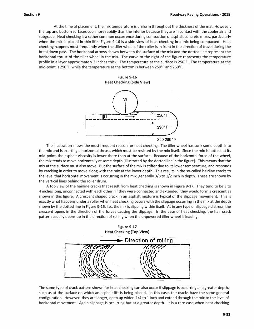
Section 9 Roadway Paving Operations - 2019
9-33
At the time of placement, the mix temperature is uniform throughout the thickness of the mat. However,
the top and bottom surfaces cool more rapidly than the interior because they are in contact with the cooler air and
subgrade. Heat checking is a rather common occurrence during compaction of asphalt concrete mixes, particularly
when the mix is placed in thin lifts. Figure 9-16 is a side view of heat checking in a mix being compacted. Heat
checking happens most frequently when the tiller wheel of the roller is in front in the direction of travel during the
breakdown pass. The horizontal arrows shown between the surface of the mix and the dotted line represent the
horizontal thrust of the tiller wheel in the mix. The curve to the right of the figure represents the temperature
profile in a layer approximately 2 inches thick. The temperature at the surface is 250°F. The temperature at the
mid-point is 290°F, while the temperature at the bottom is between 250°F and 260°F.
Figure 9-16
Heat Checking (Side View)
The illustration shows the most frequent reason for heat checking. The tiller wheel has sunk some depth into
the mix and is exerting a horizontal thrust, which must be resisted by the mix itself. Since the mix is hottest at its
mid-point, the asphalt viscosity is lower there than at the surface. Because of the horizontal force of the wheel,
the mix tends to move horizontally at some depth (illustrated by the dotted line in the figure). This means that the
mix at the surface must also move. But the surface of the mix is stiffer due to its lower temperature, and responds
by cracking in order to move along with the mix at the lower depth. This results in the so-called hairline cracks to
the level that horizontal movement is occurring in the mix, generally 3/8 to 1/2 inch in depth. These are shown by
the vertical lines behind the roller drum.
A top view of the hairline cracks that result from heat checking is shown in Figure 9-17. They tend to be 3 to
4 inches long, unconnected with each other. If they were connected and extended, they would form a crescent as
shown in this figure. A crescent shaped crack in an asphalt mixture is typical of the slippage movement. This is
exactly what happens under a roller when heat checking occurs with the slippage occurring in the mix at the depth
shown by the dotted line in Figure 9-16, i.e., the mix is slipping within itself. As in any type of slippage distress, the
crescent opens in the direction of the forces causing the slippage. In the case of heat checking, the hair crack
pattern usually opens up in the direction of rolling when the unpowered tiller wheel is leading.
Figure 9-17
Heat Checking (Top View)
The same type of crack pattern shown for heat checking can also occur if slippage is occurring at a greater depth,
such as at the surface on which an asphalt lift is being placed. In this case, the cracks have the same general
configuration. However, they are longer, open up wider, 1/4 to 1 inch and extend through the mix to the level of
horizontal movement. Again slippage is occurring but at a greater depth. It is a rare case when heat checking

Roadway Paving Operations - 2019 Section 9
9-34
occurs under a drive-wheel of a steel roller. It almost always occurs under the tiller wheel. Steel-wheeled rollers
should not have ballast in the tiller wheel. The heavier the weight in the small diameter wheel, the deeper it sinks
into the mix with a resulting increase of horizontal force being imparted during the rolling operation, and the
greater likelihood of heat checking or other slippage distress.
(B) Environmental Effects
As explained above, the rate at which the mix cools affects the length of time during which density can and must
be achieved. Cool air temperatures, high humidity, strong winds, and cool surfaces, either individually or in
combination shorten the time in which compaction must take place and may also make compaction more difficult.
When any of these conditions exist, it is extremely important that the compaction rolling operation follow closely
behind the paver so there is no delay between placing and compacting the mat. When thin lifts are being placed
from late fall to spring or during cool weather, this is especially true if specification density and tight, smooth
surface textures are to be achieved.
(C) Layer Thickness
Generally speaking, it is easier to achieve target density in thicker layer (lifts) of asphalt concrete than in thinner
ones. This is because the thicker the mat the longer it retains its heat and the longer the time during which
compaction can be achieved. This can be used to advantage when rolling lifts of highly stable mixes that are difficult
to compact, or when paving in weather that can cause rapid cooling of thin mats. Alternatively, increased course
thickness can permit lower mix temperatures to be used because of the reduced rate of cooling. (see Table 9-2)
(D) Subgrade and Bases
The subgrade or base must be firm and non-yielding under the haul trucks and other construction compaction
equipment. Subgrades or bases that show movement under trucks or construction equipment will need additional
compaction work or some type of remedial work to overcome the softness. The remedial work could be lime or
Portland cement stabilization, or in certain circumstances, removal and replacement with a more suitable material.
A yielding subgrade or base would require a thicker asphalt pavement in order to support the traffic loading. Haul
trucks may also be limited in size and weight to prevent pumping action of base materials. If remedial action is not
performed to correct a yielding subgrade or base, (i.e. a resurfacing project), then it may be difficult to achieve the
specified density.
(E) Compaction Equipment and Procedures
Compaction is done by any of several types of compactors, or rollers – vehicles which, by their weight or by exertion
of dynamic force, compact the pavement mat by driving over it in a specific pattern. Compaction aims at producing
a mat of specific density (target density) and smoothness. Although the compaction process appears rather simple
and straightforward, it is, in reality, a procedure requiring skill and knowledge on the part of the roller operator
and the technician. Both must have a thorough understanding of the mechanics of compaction and the factors
that affect the compaction effort.
9.8.2 Three Phases of Rolling
There are three basic phases in the compaction process of asphalt pavements:
(A) Breakdown phase;
(B) Intermediate phase;
(C) Finish phase.
Each of these are described in detail below.
(A) Breakdown Rolling
Breakdown rolling is best accomplished with steel-wheeled rollers. Either static-weight or vibratory tandem rollers
may be used. Vibratory rollers may be used in the vibratory mode on all mixes, except that on the final wearing
surface the thickness must be 1 inch or greater before use is permitted. The weight of the roller used for breakdown
rolling depends to a large degree upon the temperature, thickness, and stability of the mix being placed. Generally,
a roller weighing from 8 to 12 tons is used for this operation.
Many old compaction specifications recommend the compaction process begin on the low side of the pavement
lane and proceed upwards toward the high side. With modern compaction equipment and more stable mixes, this
process is usually unnecessary unless the superelevation is extreme or the mix lift is thick in relation to its aggregate
size. When adjoining lanes are placed, it is normally best to compact the longitudinal joint by placing the majority

Section 9 Roadway Paving Operations - 2019
9-35
of the roller on the hot (new) mat and overlapping the joint by a distance of approximately 6 inches over the cold
mat. This way the majority of the compaction effort is where it is needed - on the new mat.
(B) Intermediate Rolling
Second or intermediate rolling should closely follow breakdown rolling while the asphalt mix is still plastic and at a
temperature that is still well above the minimum temperature at which compaction can be achieved, preferably
225° - 250°F. Pneumatic-tired, steel-wheeled static and vibratory rollers may be used for intermediate rolling.
When using pneumatic rollers, keeping the tires hot is the most effective means of preventing pickup. Applying a
small amount of non-foaming detergent or water soluble oil on the wetting mat of a pneumatic-tired roller at the
beginning of rolling operations helps prevent asphalt from sticking to the tires until they warm up.
Pneumatic-tired rollers have several advantages:
a. They provide a more uniform degree of compaction than steel-wheeled rollers;
b. They improve the seal near the surface, thus decreasing the permeability of the layer; and
c. They orient the aggregate particles for greatest stability, as high pressure truck tires do after using the
asphalt surface for some time.
Tire contact pressures should be as high as possible without causing displacement of mix that cannot be remedied
in the final rolling. Pneumatic-tired rolling should be continuous after breakdown rolling until all of the mix placed
has been thoroughly compacted. At least three passes should be made. Turning of pneumatic-tired rollers on the
paving mix should not be permitted unless it can be done without causing undue displacement.
Vibratory tandem rollers of proper static weight, vibration frequency and amplitude are used to provide required
densities with fewer roller passes than static-weight tandem or pneumatic-tired rollers (or combinations of the
two). As mentioned previously, the vibratory roller may be used in the vibratory mode, at any time (subject to
Specification requirements) on all pavement layers during the breakdown and intermediate phases of rolling.
(C) Finish Rolling
Finish rolling is done primarily for the improvement of the surface. It should be accomplished with steel-wheeled,
static-weight tandems or non-vibrating vibratory tandems while the material is still warm enough for removal of
roller marks. Only enough passes should be made to remove the roller marks and smooth the mat. Finish roller
operators should be cautioned about over rolling the mat since it can decrease the mix density. Vibratory rollers
operated in the vibratory mode are not permitted as finish rollers.
9.8.3 Roller Patterns
A rolling pattern that provides the most uniform coverage of the lane being paved should be used. Rollers vary in
widths, and a single recommended pattern that applies to all rollers is impractical. For this reason, the best rolling pattern
for each roller being used should be worked out and followed to obtain the most uniform compaction across the lane. For
purposes of this and future discussion, the following definitions apply. A roller "pass" is defined as one trip of the roller in
one direction over any one spot in the pavement. A “coverage” is defined as the sufficient number of passes to cover the
entire laydown width of pavement.
The rolling pattern not only includes the number of passes, but also the location of the first pass, the sequence of
succeeding passes, and the overlapping between passes. Breakdown rolling speed should not exceed about 3 mph. In
addition, sharp turns and quick starts or stops are to be avoided. For thin lifts, a recommended rolling pattern for static
steel-tired rollers is shown in Figure 9-18. The rolling operation should start from the edge of the spread on the low side
with the roller moving forward as close behind the paver as possible. The second movement of the roller should be to
reverse in the same path until the roller has reached previously compacted material. At this point it should swing over and
move forward along path number 3, again going as close as possible behind the paver. The fourth movement is reversal in
the third path and a repetition of the previous operation. After the entire width of the mix being placed has been covered
in this fashion, the roller should swing across the spread to the low side and repeat the process. With this pattern, the lap
of the roller with succeeding passes need not be more than 3 to 4 inches.

Roadway Paving Operations - 2019 Section 9
9-36
Figure 9-18
Correct Rolling Pattern
For thick-lift construction, the rolling process should start 12 to 15 inches from the lower unsupported edge until
the center portion of the spread is compacted to some degree of stability. Succeeding passes of the roller should then
gradually progress toward the edges of the spread. The uncompacted edge provides initial confinement during the first
pass, thus minimizing lateral movement of the mix. After the central portion of the spread has been compacted, the mix
will support the roller and allow the edge to be compacted without lateral movement.
With steel-wheeled rollers the operation should always progress with the drive wheel forward in the direction of
paving. This is especially important in breakdown rolling. The greatest percentage of compaction occurs during a
breakdown pass. A main reason why breakdown rolling should be done with the drive wheel is that there is a more direct
vertical load applied by this wheel than the tiller wheel (see Fig. 9-19).
If the breakdown pass of the roller is made with the tiller wheel forward, the pushing force and the weight is slightly
ahead of vertical, causing material to push up in front of the wheel. The greater weight of the drive wheel carries out the
compaction while the turning force tends to tuck material under the front of the wheel. There are exceptions to rolling
with the drive wheel forward, however. They usually occur when superelevations are being constructed or if the grade on
which the asphalt mix is being placed is excessive. The exceptions occur when, due to these high grades, the drive wheel
of the roller begins to chatter on the mat, causing displacement of the mix and a very rough surface. In these cases the
roller must be turned around to allow the tiller wheel to partially compact the material so that the drive wheel can then
proceed over it.
Figure 9-19
Forces Acting When Tiller Wheel or Drive Wheel is Forward

Section 9 Roadway Paving Operations - 2019
9-37
9.9 CONSTRUCTING TRANSVERSE JOINTS
9.9.1 Transverse Joint Specifications
When the placing of the mixture is to be suspended long enough to permit the mixture to become chilled, construct
a transverse joint (see Table 9-2). If traffic will not pass over the end of the paving, a butt joint will be permitted, provided
proper compaction is achieved. If traffic will pass over the joint, construct a sloped wedge ahead of the end of the full depth
pavement to provide for proper compaction and protection of the full depth pavement. Construct the joint square to the
lane alignment and discard all excess material. Place a paper parting strip beneath this wedge to facilitate joint construction
unless waived by the Engineer.
Before paving operations are resumed, remove the sloped wedge and cut back into the previously constructed
pavement to the point of full pavement depth. Coat the exposed edge of the previously constructed pavement with tack
coat. When laying of the mixture is resumed at the joint, complete and then test the construction and smoothness of the
joint in accordance with Article 610-12 while the mixture is still in a workable condition and can be corrected.
9.9.2 Construction Procedures A transverse joint is constructed at any point where the paving operation is interrupted for a period of time (15
minutes or more) and the paving operation is to be resumed later. The type of transverse joint to be constructed depends
primarily on whether traffic will be traveling over the mat before paving is resumed. A poorly constructed transverse joint
is noticeable as a pronounced bump in the pavement. Consequently, the technician must be on hand whenever a transverse
joint is made in order to ensure it is done properly. Discovering hours after construction that a transverse joint is
unsatisfactory does no good, because joint construction can only be corrected while the mix is still hot and workable. Once
the mix cools, corrections can be made only by cutting out and replacing the joint.
Transverse joints are constructed in three steps: (A) ending the lane or width of pavement (with proper compaction
and thickness) at the point of work stoppage, (B) resumption of paving operations at a subsequent time, and (C) rolling the
transverse joint. These steps are described below.
(A) Ending a Lane:
When ending a lane (for whatever reason) and paving is to be later resumed, the objective is to end with full depth
pavement and to establish a vertical face on the mat such that when paving is resumed, full depth pavement can
be placed, beginning at the joint. This can be accomplished by the use of either a butt joint or a paper tapered joint
as required by the traffic situation. Ending a lane should generally be done in the following manner.
(1) When the paver is placing the last load, operate the paver in normal fashion as it approaches
the location of the proposed joint.
(2) As the hopper begins to empty and the amount of material in the screed chamber decreases
below normal operating level, the paver is stopped.
(3) The screed is raised and the paver moved out of the way.
(4) Excess asphalt mix is then shoveled away from the end of the mat to form a straight, full
thickness, clean, vertical edge at the selected location.
(5) If a butt joint is to be constructed, place runoff boards of sufficient thickness, length, and depth
next to the joint to support the roller during compaction so as to result in a full depth mat with
a vertical face. Complete compaction and remove boards as necessary.
(6) If a paper tapered joint is required, place treated release wrapping paper is placed along the
edge as shown in Figure 9-20. Paper joints are required per Standard Specifications Article
610-11, unless waived by the Engineer. The material that was shoveled away in Step 4 is
replaced and used to form a taper. The suggested minimum length to compacted thickness
ratio of the taper is 12:1.
(7) Compact the mat to the required density.

Roadway Paving Operations - 2019 Section 9
9-38
Figure 9-20
Paper Joint
(B) Resumption of Paving Operations:
When construction is ready to be resumed, the following procedure is used to form a smooth and durable
transverse joint.
(1) The taper material is removed and discarded or recycled along with the board or paper.
(2) A 10 ft. straightedge is used to check the longitudinal grade of the mat. Because the paver was running
out of material as it laid the last few feet of mat, it is possible that those last few feet taper slightly (ramp
down) from the specified level of the mat. If this is the case, a new transverse vertical edge must be cut
at the point of full pavement depth behind the point where the ramping down begins.
(3) The vertical face and pavement surface of the mat is tack-coated.
(4) The paver is backed up to the edge of the mat and the screed rested on the mat surface.
(5) The screed is heated while it rests on the mat. This provides some heat to the material at the edge of the
mat.
(6) The heated screed is raised and at least 3 shims or starting blocks as thick as the difference between the
uncompacted and compacted mat are positioned under it. The starting blocks should extend the full
length of the screed, front to back.
(7) Null the screed and set the proper angle of attack on both sides of the paver.
(8) The truck with the first load of mix is backed carefully to the hopper. During discharge of the mix from
the truck bed to the paver, it is essential that the truck not bump the paver, and cause it to move.
(9) Activate the material feed system and bring the head of material in the auger chamber up to the proper
level (up to the auger shaft) across the entire width of the screed.
(10) Start the paver forward, pull the screed off the starting blocks, and bring the paver to the desired laydown
speed as quickly as feasible. Adjust the angle of attack as necessary to provide the proper loose thickness
of the asphalt mat.
(11) Once the paver has moved away, excess mix is cleaned off the surface of the mat and the joint is checked
with a straightedge to assure smoothness and that adequate loose material has been placed to allow for
compaction.
(C) Rolling and Compacting Transverse Joints:
Ideally, a transverse joint should be rolled transversely; however, because of maintaining traffic, site restrictions,
safety, slopes, etc., most transverse joints are rolled in the longitudinal direction. This can be satisfactorily
accomplished as long as the initial elevation of the new mix is sufficiently above that of the old mix on the cold
side of the joint to allow for full compaction. Rolling and compaction should be accomplished as quickly as possible
after the paver has moved off the joint and checked for smoothness and loose thickness relative to the elevation
of the cold side of the joint. The roller should pass slowly and completely over the joint before the roller is reversed.
Once the joint has been compacted, it must be checked for smoothness. Do not exceed 1/8 in (3.2mm) variation
between any two contact points using a 10 ft. straightedge. If the joint is satisfactory, no further work is necessary.
If the straightedge shows an uneven joint, the surface of the new mat must be scarified while still warm and
workable. Scarification is done, preferably with a tined lute. Excess material can then be removed or additional
material added, and the joint rolled and rechecked.

Section 9 Roadway Paving Operations - 2019
9-39
9.10 CONSTRUCTING LONGITUDINAL JOINTS
9.10.1 Longitudinal Joint Specifications
Tack the exposed edge of all longitudinal joints prior to placing the adjoining pavement. Form longitudinal joints
by allowing the paver to deposit the mixture adjacent to the joint to such depth that maximum compaction can be obtained
along the joint. Pinch the joint by rolling immediately behind the paver.
When multi-lane multi-layer construction is required, offset the longitudinal joints in each layer from that in the
layer immediately below by approximately 6 inches. Construct the joints in the final layer, where possible, between
designated travel lanes of the final traffic pattern.
9.10.2 Location of Longitudinal Joints
The location of longitudinal joints must be carefully planned to achieve durable joints. The width of spread is
controlled in many instances by the location of the longitudinal joint. When a multi-lane multi-layer pavement is being
constructed, the longitudinal joints in each layer must be offset from the joint in the layer immediately below by
approximately 6 inches (see Fig. 9-22). Overlapping of successive courses rather than stacking the joint directly on top of
the joint below helps to prevent cracking and separation along the longitudinal joint. The locations of joints must also be
planned such that the joint in the final layer of pavement is located, where possible, between designated travel lanes of the
final traffic pattern. This will assure that the joint is not located in the wheel path of a lane. Joints located in a wheel path
have a detrimental effect on ride quality and are more susceptible to water intrusion under traffic during rain or snow.
Figure 9-22
Overlapping of Successive Courses To Prevent A Crack From Opening Along a Longitudinal Joint
9.10.3 Construction of the First Lane
Two key factors that affect the long term durability of a longitudinal joint are built into the pavement during
construction of the first lane. One is the importance of running the paver in a straight line so the joint can be matched on
the next pass of the paver. The other is the need to properly compact the unconfined edge of the first lane. In laying the
first lane, a string line, curb, or other reference line must be used to guide the paver on the proper course. It is also
important, for good results, that the thickness adjustment controls on the paver not be over-controlled. If an extendable
screed is used, its width must be kept constant. Moving the extension in and out will create an uneven edge that will be
very difficult to match.
To achieve proper density at the longitudinal joint, it is essential to compact the unconfined edge of the first lane
correctly. The edge of the drum on a vibratory or steel wheel roller should extend out over the edge of the mix a minimum
of 6 inches when the first lane is being compacted.
9.10.4 Construction of the Adjoining Lane
Tack the exposed edge of all longitudinal joints prior to placing the adjoining pavement.
Form the longitudinal joint by allowing the paver to deposit mixture adjacent to the joint to such depth that
maximum compaction can be obtained along the joint. If the level of the new uncompacted mix is even with or below the
level of the adjacent compacted mix, steel wheel compaction equipment will not be able to properly densify the mix along
the joint. Whether the first pass of the roller is primarily on the hot side of the joint or primarily on the cold side, the roller
will bridge the mix at the joint leaving it essentially uncompacted or only partially compacted. Therefore, it is imperative
that the level of the uncompacted mix at the longitudinal joint be above that of the compacted mix by approximately 1/4"
for each 1" of compacted pavement. The longitudinal joint should be rolled immediately behind the paving operation.

Roadway Paving Operations - 2019 Section 9
9-40
When placing the adjoining lane, it is important that the adjoining lane be placed so that the mix uniformly overlaps
the first lane by 1 to 1.5 in. (see Fig. 9-23a). The thickness of the overlap should be about one-fourth the desired compacted
thickness. This is the preferred method of longitudinal joint construction. If the longitudinal edge of the first lane is straight
and the correct amount of overlap is used, the amount of raking will be minimal. If the overlapped material is slightly
excessive, the excess overlapping material may be bumped or crowded back onto the hot lane so that the roller can crowd
the small excess into the hot side of the joint (see Fig. 9-23b). When the overlap is excessive, the excess material should be
trimmed off so that the bumped ridge of material along the joint is uniform. In no case should the raker broadcast the
excess mix across the width of the new lane.
A trimmed joint is sometimes used (see Fig. 9-23c). This joint is constructed by removing all freshly placed material
that has overlapped the rolled lane. This is best done by trimming the joint immediately behind the paver with a square-
ended shovel. Again, in no case should the mix be broadcast across the width of the new lane.
If the lanes are placed simultaneously with two pavers moving in echelon, the loose depths of the mats should
match exactly, with no overlap for a hot joint. The joints of a freshly paved mat are usually compacted before the rest of
the paved width.
Figure 9-23
Constructing and Preparing Longitudinal Joints
9.10.5 Rolling and Compaction of Longitudinal Joints
Longitudinal joints should be rolled directly behind the paving operation. The most efficient and recommended
way to compact a longitudinal joint is to place the roller on the hot (new) mat so that approximately six (6) inches rides on
the cold (existing) adjoining lane (Fig. 9-24 and Fig. 9-25). The roller is operated here to pinch and press the fines into place
and provide adequate compaction to the joint and the hot mat adjoining the joint.
In the past it was common practice to do the initial rolling of the longitudinal joint from the cold side of the joint,
frequently referred to as “pinching the joint”. On the first pass, only about 6 in. of the width of the roller rides over the
fresh mat, compressing the mix at the joint. The majority of the compactive force is wasted because the roller is essentially
applying its compactive force to an already compacted mat. In the meantime, the rest of the mat is cooling, possible causing
density to be more difficult to achieve.
Regardless of the rolling method or equipment used, the level of the uncompacted mix at the longitudinal joint
must be above that of the previously compacted mix by an amount equal to approximately 1/4 in. for each 1 in. of
compacted pavement if proper compaction of the mix at the joint is to be accomplished. If it is not, the compaction
equipment will bridge the mix at the joint, leaving it essentially uncompacted or only partially compacted.

Section 9 Roadway Paving Operations - 2019
9-41
Figure 9-24
Rolling a Longitudinal Joint
Figure 9-25
Joint Rolling Procedure
9.11 SIGNIFICANT DECIMALS FOR ROADWAY CALCULATIONS
The following rule of “rounding off” shall be used in all calculations. When the digit to be dropped (one digit beyond
significant digit) is 0, 1, 2, 3 and 4, the preceding digit will not change. When the digit to be dropped (one digit beyond
significant digit) is 5, 6, 7, 8 and 9, the preceding digit will be increased by one.
NOTE: Do not round one digit beyond the significant decimal prior to rounding to the specified significant decimal.
Example: Significant decimal of 0.1
91.74 will be 91.7 (Drop the 4 and leave the 7 as is)
91.75 will be 91.8 (Drop the 5, and round up the 7 to a 8)
NOTE: Each internal calculation used to arrive at a final combined result shall be calculated to at least one decimal
place farther than the specified significant decimal.
Significant Decimals
Specific Gravities (All) 0.001
Prime Coat Rate 0.01 gal/yd2
Tack Coat Rate 0.01 gal/yd2
Rate of Mix Spread 1 lbs/yd2
Tons of Mix 1 Ton
% Compaction (Density) 0.1%
Random Density Sample Locations 1 L.F. (Length and Width)
Nuclear Target Density 0.1 lbs./ft3

Roadway Paving Operations - 2019 Section 9
9-42

Section 10 Roadway Inspection & Testing – 2019
10-1
SECTION 10 ROADWAY INSPECTION AND TESTING OF ASPHALT PAVEMENTS
10.1 ROADWAY INSPECTION
10.1.1 General
Prior to beginning paving operations, the Resident Engineer and/or the DOT Roadway technician must inspect the
Contractor's equipment to assure that it meets all requirements of the Specifications and is in good working order. If the
equipment meets Specifications and is in satisfactory operating condition, a statement shall be entered in the Technician's
Daily Diary. If the equipment does not meet the Specifications, the Contractor should be advised accordingly and corrective
actions taken before paving begins. The technician should note in his daily diary on the first day of operation, and thereafter
as needed, that this check has been made and that all equipment is in compliance with specifications, or if not, what
measures are being taken to correct the deficiencies.
After paving begins on a contract, the DOT Roadway technician is responsible to insure the Contractor is utilizing
good construction practices in order to generate a satisfactory asphalt pavement. Article 105-10 authorizes the technician
to inspect all or any part of the work. If the Roadway technician finds the Contractor is not utilizing best paving practices,
he/she should notify the Contractor’s paving foreman and the Resident Engineer. The technician is not authorized to alter
or waive the requirements of the contract or to act as foreman for the Contractor; however, the technician does have the
authority to reject work or materials until a final decision is made by the Engineer.
10.1.2 QC/QA Technicians Checklist for Roadway Operations
Prior to beginning production and placement of asphalt mixtures, the following checklist should be reviewed by
project technicians, including both Contractor and Department technicians. The checklist is taken from the Construction
Manual and includes items related to preliminary planning, equipment specifications and requirements, preparation of the
existing pavement or base, spreading, compaction, traffic control, sampling/testing and required reports.
1. GENERAL
a) Have the Engineer and Inspectors held a preliminary paving conference with the appropriate Contractor personnel
and other involved parties? (See Section 9.4.2)
b) Has the continuity of operations been planned?
c) Has the number and type of rollers to be used been determined?
d) Has the width of spread and location of longitudinal joints been planned to coincide with lane markings, where
possible and feasible?
e) Is it understood who is to issue and receive instructions?
f) Has placement of control strips and coring of density samples been coordinated?
g) Has method of handling traffic been established?
h) Is a Materials Transfer Vehicle required?
2. PAVER
a) Does the paver comply with specifications?
b) Is the governor on the engine operating properly?
c) Are the slat feeders, the hopper gates, and spreader screws in good condition and adjustment?
d) Are the crawlers (power tracks) in good condition and adjusted properly?
e) If the paver has pneumatic tires, is the air pressure in accordance with manufacturer's specifications?
f) Is the screed heater working properly?
g) Are the reverse auger paddles in good condition?
h) Are auger extensions needed and installed?
i) Are the paver strike-off plates in place and correctly adjusted?
j) Are the surfaces of the screed plates true and in good condition?
k) Are screed cutoffs and/or extensions in accordance with specifications and properly adjusted?
l) Are mat thickness and crown controls in good condition and adjustment?
m) Are screed vibrators in good condition and adjustment and being used on all pavement courses?
n) Are the automatic screed controls operating properly, when required?
o) Is the mobile string line for the automatic grade controls of adequate length and operating properly, when
required?

Roadway Inspection & Testing - 2019 Section 10
10-2
3. ROLLERS
a) Does the type, number and weight of rollers comply with specifications?
b) Can each roller start, stop and reverse smoothly?
c) Are all steel wheels straight across and free from grooves or pits?
d) Are wheel bearings free from excessive wear?
e) Are scrapers and wetting pads in good condition?
f) Is the sprinkler system on each roller in good operating condition?
4. HAULING EQUIPMENT
a) Are truck beds smooth and free from holes and depressions?
b) Is there any leakage of gas or oil from trucks?
c) Are trucks equipped with adequate covers?
d) Do trucks and paver operate together without interference?
e) Is the method of coating of contact surfaces of truck beds agreed upon?
f) Are truck bodies being drained of excess release agent before being loaded?
g) Is there a hole provided for temperature check?
5. ASPHALT DISTRIBUTOR
a) Are the heaters and the pump in good working condition?
b) Does the distributor have a volume calibration chart certified by a private testing laboratory?
c) Are spray bar nozzles unclogged & set at proper angle for application of tack coat?
d) Is an adequate thermometer provided?
e) Is a hand held spray hose with nozzle provided to tack irregular areas?
6. MISCELLANEOUS TOOLS REQUIRED
a) Rakes, Shovels, Lutes, Etc.
b) Tool heating torch
c) Cleaning equipment
d) Hand tampers
e) Small mechanical vibrating compactors, when considerable areas require tamping
f) Blocks and shims for supporting the screed of the paver when beginning operations
g) Paper or timbers for construction of transverse joints at ends of runs
h) Joint cutting and painting (tacking) tools
i) Thin Lift Nuclear Density Gauge or Non-Nuclear Density Gauge (if density gauge control used)
j) 10 foot straightedge on hand for checking joints and other locations (see Article 610-12 of the Specifications)
k) 4 foot level for checking pavement crown or cross-slope
l) Infrared Thermometer
m) 6” Core Drill Bit – must be 6” (150mm) inside diameter
n) Depth Checking Device
o) Hearne Straightedge (when required by contract)
p) Inertial Profiler (when required by contract)
7. PREPARATION OF EXISTING PAVEMENT FOR OVERLAY
a) Has patching of all pot holes and other necessary patches been made?
b) Has all grass, dirt debris, etc. been properly removed from the pavement?
c) Have all vertical faces, which will come into contact with the asphalt mix, been cleaned and tacked with asphalt?
d) Has a uniform tack coat of correct quantity been applied?
e) Has stringline been placed for proper alignment?
8. PREPARATION OF BASE COURSES BEFORE APPLICATION OF ASPHALT PLANT MIX
a) Have all underlying base courses and/or subgrade been compacted to the required density?
b) Has base course been primed when required?
c) Has prime cured sufficiently and has excess prime been blotted to avoid pickup?
d) Has base been broomed to remove loose material if necessary?
e) Has stringline been placed for proper horizontal alignment of the pavement?

Section 10 Roadway Inspection & Testing – 2019
10-3
9. SPREADING
a) Is the mix of uniform texture?
b) Is the temperature of the mix uniform and according to requirements of Specifications and job mix formula?
c) Is the depth and rate in conformance with contract?
d) Is the alignment and cross-section according to typical section?
e) Are longitudinal and transverse joints being properly constructed and checked?
f) Is paver speed coordinated with plant production rate?
10. COMPACTION
a) Are the required number of rollers being used?
b) Are the rollers operating at the proper speed?
c) Is the proper rolling pattern being uniformly followed?
d) Is the mat being rolled at the proper temperature?
e) Are the joints and edges being rolled properly and checked?
f) Are transverse joints being properly constructed when necessary?
g) Is the required density being achieved?
11. HANDLING OF TRAFFIC
a) [See Project Special Provisions, Standard Specifications, and Roadway Standards.]
b) Is traffic being handled properly through project?
c) Are the signs of sufficient type and number?
d) Are there proper amount of flagmen to handle traffic where necessary?
e) Is Contractor's equipment being operated in a safe manner through project?
10.1.3 Required Information for Asphalt Weight Tickets
Upon delivery of asphalt to the roadway, the Contractor should immediately give the weight certificate to the DOT
roadway technician performing the inspection. Upon receipt of the certificate, the roadway technician should make sure
the ticket is legible and the following required information has been listed on the ticket correctly by the certified
weighmaster at the plant:
1. The Department Contract Number/ WBS Number.
2. The date the ticket is issued.
3. The time the ticket is issued.
4. The type of material represented by the ticket.
5. The gross weight of the vehicle. (if platform scales are used)
6. The tare weight of the vehicle. (if platform scales are used)
7. The net weight of the material.
8. The appropriate Job Mix Formula # (JMF) for the asphalt plant mix.
9. The asphalt plant certification number where the material was produced.
10. The truck number transporting the material.
11. The name of the Contractor.
12. The stamp or number of the public weighmaster weighing the material.*
13. The signature or initials of the public weighmaster in ink or in electronic format.*
(*Computer-generated weightmaster’s stamp & signature are acceptable as long as the system generating the tickets
meets the latest NCDA&CS Standards Division requirements.)
After verifying that the above information has been furnished on the weigh ticket, the DOT roadway technician should then
list the following information on the ticket:
1. Contract / WBS Number if different than that shown on the ticket.
2. Contract line item number by which the material will be paid.
3. Beginning station location where the material is being placed.
4. Lane or shoulder description where the material is being placed.
5. Time the material was placed.
6. The temperature of the mix when it is received.
7. Construction technician’s signature on first ticket for day and initials on subsequent tickets.
8. Quantity reduction for unused portion of material and reason for deduction.

Roadway Inspection & Testing - 2019 Section 10
10-4
10.1.4 Visual Inspection of the Mix (Plant and Roadway)
Close cooperation between the paving crew and the asphalt plant is essential in producing a high quality pavement
on the roadway. A fast means of communication must be established between the paving operation and the asphalt plant
so that any change in the mixture production process or the roadway operation can be made promptly. When possible,
the roadway technician and the plant technician should frequently exchange visits. When the roadway technician is familiar
with plant operations, he can easily determine if changes at the plant are necessary to improve the mix. The plant
technician, on the other hand, by being familiar with the paving operation can better understand related roadway problems
which might occur due to changes at the plant.
Every truckload of material should be observed as it arrives. Mistakes in batching, mixing, and temperature control
can and do occur, and these errors may sometimes go unnoticed by the plant technician. Consequently, loads arriving at
the spreader may be unsatisfactory, in which case, they should be rejected by either the Contractor or DOT technician.
When the roadway technician rejects a load, he should record his action, with the reason for rejection, both on the ticket
and in his diary so that the proper deduction can be made from the pay quantities. If appropriate, a sample should be
obtained for laboratory analysis. A record should also be kept of the loads accepted and placed. These records should be
checked daily, or more frequently, with those of the plant technician so that discrepancies do not exist when work is
completed.
Although the mix is inspected at the plant, there are times when the plant technician may inadvertently overlook
a defective load resulting from a plant malfunction. Some of these deficiencies can be readily noticed by a knowledgeable
and alert roadway technician prior to or immediately after dumping. When the temperature is checked or the truck bed is
raised, these deficiencies are usually readily apparent based on visual observation and knowledge of asphalt pavements.
Some indications of hot-mix deficiencies that may require close inspection and possible corrective action are:
(1) Blue Smoke: Blue smoke rising from the mix in the truck or the spreader hopper may indicate an overheated
batch. The temperature should be checked immediately.
(2) Stiff Appearance: Generally, a load that appears stiff or has peaked up in the truck body may be too cool to
meet specifications. The temperature should be checked. If it is below the optimum placing temperature, but
within the acceptable temperature range, immediate steps should be taken to correct the low temperature and
decrease the possibility of having to waste loads of mix.
(3) Mix Slumped in Truck: Normally the material in the truck is in the shape of a dome. If a load lies flat or nearly
flat, it may contain too much asphalt or excessive moisture. Close inspection should be made at once. Excess
asphalt also may be detected under the screed as excessive shininess on the mat surface. A mix containing a
large amount of coarse aggregate might be mistaken for an over-asphalted mix because of its shiny appearance.
Such a mix, however, usually will not slump in the haul truck.
(4) Lean, Dull Appearance: A mix that contains too little asphalt can generally be detected immediately in the truck
or in the spreader hopper by its lean (dry), granular appearance; improper coating of the aggregate, and lack of
typical shiny black luster. Lack of sufficient asphalt in the mix can be detected on the road by its lean, brown,
dull appearance on the surface and unsatisfactory compaction under the roller. Excess fine aggregate can cause
a mix to have the same look as a mix with too little asphalt. Excess fines can be detected by inspecting the mix
texture and by watching for shifting of the mix under the roller.
(5) Rising Steam: Excess moisture in the mix often appears as steam rising when it is dumped into the hopper of
the paver. The hot-mix mat behind the paver may be bubbling and popping as if it were boiling. Excessive
moisture causes the binder to expand, which in turn, may also cause the mix to appear and act as though it
contains excessive asphalt.
(6) Segregation: Segregation of the aggregates in the mix may occur during paving because of improper handling
or it may have happened at some point prior to the mix reaching the paver. In any case, corrective action should
be taken immediately. There are many possible causes of segregation. The cause of the segregation should be
corrected at its source. (See the “Segregation Diagnostic Chart” in the Appendix and “Segregation of Mixes
on the Roadway” in Section 10.1.8 for possible solutions).
(7) Contamination: Mixes can become contaminated by a number of foreign substances, including spilled gasoline,
kerosene, oil, rags, paper, trash and dirt. The contamination can be removed if it is not too extensive; however,
a load that has been thoroughly contaminated should be rejected.
Diesel fuel is NOT an approved Truck Release Agent and should NEVER be used. Excess diesel fuel that
collects in the truck bottom can be absorbed by the mix. Diesel fuel damages the asphalt and causes it to
ooze (bleed) to the surface, resulting in what is termed a "fat spot". Also, the excess diesel fuel will strip
the asphalt from the mix with which it comes into contact. Asphalt contaminated with diesel fuel should
be removed and replaced. Only non-petroleum/non-citrus based agents are allowed for spraying truck
beds. The approved list of release agents is available through the Asphalt Laboratory.

Section 10 Roadway Inspection & Testing – 2019
10-5
10.1.5 Identifying Mat Problems, Causes and Cures
Roadway technicians, including both Contractor and Department personnel, must be able to quickly identify
problems in the finished pavement and determine possible causes and cures of problems. A table of these and other
common pavement problems and their probable causes titled “Mat Troubleshooting Guide” can be found in the Appendix.
In referring to the table, keep in mind that a given deficiency may have several possible causes. Sampling and testing is not
the only means for analyzing a pavement problem. Problems can still occur on the Roadway even though asphalt test
results are within NCDOT specifications. The Contractor shall be placed on limited production as outlined in Section 10.2
for any mix that is obviously unacceptable. Any questionable mix shall be evaluated under Article 105-3 of the
specifications.
10.1.6 Determination of Rate of Spread and Tonnage Required
NCDOT project plans and specifications normally specify that asphalt mixtures be placed at a certain rate in pounds
per square yard; therefore, the rate of spread must be regularly checked by the technician to determine that the specified
amount is being placed. The running rate of spread may be obtained at intervals by using the running total pounds divided
by the square yards upon which the material was placed. At the end of each day's operation, the technician must also
compute the actual rate of spread from his record of the loads accepted and used in the work and record this on his daily
report. The rate of spread on mainline paving should be calculated and reported with separate calculations made for areas
of extra thickness, irregular areas, intersections, etc. An example of a rate of spread calculation is shown below:
Example Calculation of Rate of Spread
585.0 tons of Type S9.5B asphalt mix have been used to pave a mat 12 feet wide from Sta. 10+50 to 63+30 at
approximately 1.5 inches in depth. What is the rate of spread in pounds per square yard?
���������� = ��. �������������� ��. ��������������� = ��������������
ForaRectangularArea:*��+�ℎ = -����+������� − /�+�����+������� = 63 + 30� − 10 + 50� = 5280*8
���������� = 9:�����;�� × 2000=>�/����@*��+�ℎ ��. � ×A���ℎ ��. �9 ��C D�C⁄ F G= 9585���� × 2000=>�/����@5280��. × 12��.9 ��C D�C⁄ F G = 166.2=>�/D�C
Say: 166 lbs/yd2
(Note: Significant Decimal for Rate of Spread is 1 lbs/yd2)
[For Typical Rates of Spread, See Section 3.4]
Example Calculation of Tons of Mix Required
Quite frequently, the reverse of this calculation must be made when it is desired to know the number of tons of mix required
to cover a given area at a specified rate of spread.
For example, the Contractor needs to know the number of tons of material he would need to order from the plant to cover
a section of roadway 12 feet in width, from Sta. 0+00 to 28+00 with Type I19.0C mix at a specified rate of 285 lbs. per sq.
yd., at approximately 2.5 inches in depth.
:�������������� = ��. �������������>������� × �����������
:��������������� = HIJKLMNO PN.�×QRSNO PN.�TPNU VSU⁄ W× XYNKZP[\]KYS� C^^^_`a NZL⁄ � b = HICc^^PN×dCPNTPNU VSU⁄ W× I Cce_`a VSU⁄C^^^_`a NZL⁄ Wb = 532����
Say 532 tons
(Note: Significant Decimal for Tons Required is nearest 1 ton)
Also, note that the depth is not used in the rate of spread or tonnage required calculations using the above methods.

Roadway Inspection & Testing - 2019 Section 10
10-6
In addition, the actual width of spread being placed or to be placed must be used in field rate of spread or tonnage required
calculations. The width used may vary from the typical section surface width due to: (1) lane width variations due to
offsetting longitudinal joints; and (2) lower layers are wider than plan typical widths due to slope (normally 1 : 1).
10.1.7 Temperature of the Mix at Roadway
Mix temperature during laydown and compaction of the mat is critical if smoothness, texture and density are to
be achieved. It is extremely important that the temperature be at the proper level and that it be uniform throughout the
mix to achieve either and/or both of these objectives.
Trucks should be checked for the temperature requirements by measuring the temperature with a calibrated
digital or dial stem thermometer (having a probe length of 10” or greater) in the 3/8” – 5/8” hole in the side of the truck
bed prior to dumping mix into the paver. When checked in the truck at the roadway, the mix temperature must be within
±±±± 25° F of the temperature specified on the JMF. If any check of the mix temperature is outside of the above range, a
minimum of 3 additional readings should be made in different points of the load. The 4 readings should then be averaged
and the average used as the temperature of that load.
Note: Mix shall not be rejected based on the reading of a Dial Stem thermometer.
The mixing temperature at the asphalt plant will be established on the job mix formula and shall meet the
requirements of Table 610-1:
TABLE 610-1
MIXING TEMPERATURE AT THE ASPHALT PLANT
Binder Grade JMF Mix Temperature
PG 58-28; PG 64-22 250 - 290° F
PG 76-22 300 - 325° F
1) The Mix Temperature is set based on the
ranges shown in Table 610-1.
2) The Mix Temperature is found on each
JMF.
3) The Roadway Technician should use the
temperature shown on the JMF and then
apply the ±±±± 25° F for checking the mix
temperature in the truck.
Mix Temperature °F: 290
Example:
Mix Temperature (from JMF) = 290 ° F
290 ±±±± 25° F = 265 to 315 ° F
acceptable range of temperatures when
checked in the Truck at the Roadway.

Section 10 Roadway Inspection & Testing – 2019
10-7
In addition, mix temperature should be checked occasionally behind the paver or roller to determine if excessive
heat loss has occurred. Mix temperature should also be checked whenever the mix appears to be cold or when the
breakdown roller is falling behind. Mix compaction is most easily achieved and should be completed prior to mat
temperature dropping below a temperature where the mix is still workable.
Mat temperature can be taken by inserting the probe or stem of a thermometer into the uncompacted mat to the
mid-point of the mat's thickness and compacting the mat against the probe or stem by lightly tamping the mat surface, or
by use of an infrared thermometer. Asphalt mixtures cool very quickly when placed in windy conditions or on cold surfaces
in cold weather. Also, thin lifts cool more rapidly than thick lifts. If paving must be done in cold weather, then there is an
obvious advantage in placing the mix in thick lifts to gain additional time for the compaction process. (See Cessation
Requirements, Table 9-2).
10.1.8 Segregation of Mixes on the Roadway
Segregation can occur in asphalt hot mixes in two forms, either aggregate segregation or temperature segregation.
Both must be avoided if a high quality, dense, smooth, uniform surface texture mat is to be constructed. Take necessary
precautions during production, loading of trucks, transportation, truck exchanges with paver, folding of the paver hopper
wings, and conveying material in front of the screed to prevent segregation of the asphalt mixtures.
Aggregate segregation refers to a condition in hot-mix asphalt in which there is non-uniform distribution of the
various aggregate sizes across the mat to the point where the mix no longer conforms with the specified job mix formula in
gradation, asphalt content and mix properties. When segregation is present in a mixture, there is a concentration of coarse
materials in some areas of the paved mat, while other areas contain a concentration of finer materials. The resulting
pavement exhibits poor structural, textural, permeability, and smoothness characteristics, provides poor performance and
durability, and has a shorter life expectancy and higher maintenance costs.
Temperature segregation refers to a condition in which the mix varies significantly in temperature across the mat
to the point where some areas of the mat no longer comply with the temperature specification. When this happens, it
detrimentally affects the smoothness and compaction of the mat. The cold areas will not compact properly, leading to
areas with high in-place voids and overall pavement roughness. These high void areas will be more permeable and
therefore, more subject to water infiltration and significant loss of pavement life.
Problems associated with segregation of either type are serious. Segregation is one of the major causes of poor
performance and roughness of pavements. Some of the causes, and therefore the cure, of both types of segregation are
the same. Some are caused by poor production and paving practices. In any event, elimination is essential to the
construction of high quality, smooth pavements. Elimination or minimization of segregation is the responsibility of
everyone who is involved in the production and placement of HMA, including those who design the pavements and the mix,
Department personnel, Contractor personnel, aggregate producers and suppliers, those who haul the mixes, and
manufacturers who design and market asphalt mixing and paving equipment.
Segregation of either type can directly affect pavement durability by increasing the air void content of the mix in
the segregated areas and increasing the potential for moisture damage. Further, the segregated locations are susceptible
to raveling and, if bad enough, total disintegration under traffic. Segregation, in the form of coarse aggregate pockets,
longitudinal streak segregation, side-to-side segregation, or end of load (truck exchange) segregation is detrimental to the
long-term performance of the asphalt mixture. In addition, pavement roughness is almost always associated with either
type segregation.
Coarse graded mixes, such as base & intermediate mixes, are naturally more prone to aggregate segregation due
to their high coarse aggregate content, low binder content, and possibly due to gap-grading. Finer graded surface mixes do
not tend to have as severe segregation problems for the opposite reasons of those noted with coarse graded mixes;
however, they can and do frequently occur, especially in the area where the truck exchange occurs and poor paving
practices are being utilized. Aggregate segregation can originate at virtually any point in the process of hot-mix asphalt
production and placement. It can get its start in the mix design, in the aggregate stockpile, in the cold-feed bin, in the batch
plant hot bin, in the drum mixer, in the drag-slat conveyor, or in the surge-storage bin. In some cases, segregation doesn't
start until the truck is being loaded out; or even until the mix reaches the paver. The earlier in the hot mix process that
segregation begins, the worse the problem tends to be due to more movement of the mix in completing the process.
Whenever segregation does occur, all of these areas should be closely monitored for their extent of contribution to the
problem. The paving operation should be placed on limited production status until the problem is resolved. See the
“Segregation Diagnostic Chart” and “Mat Problem Troubleshooting Guide” in the Appendix.
The solution to segregation problems usually lies within several of these problem areas. Modifications in the mix
design may be needed; improper handling of the aggregates may need to be addressed; modifications to the plant, drag-
slat conveyor, and/or the surge-storage bin may be necessary; and the handling and movement of the mix through the
surge-storage bin, into the truck, and on into the paver, may need to be altered. It's most important to remember that for

Roadway Inspection & Testing - 2019 Section 10
10-8
whatever the reason and at whatever the location segregation begins, after it does, any unrestricted movement, especially
down slope movement, will compound the problem drastically. Because of this, down slope movement of the mix should
be kept to a minimum throughout the hot-mix asphalt process.
Two common mistakes often occur which greatly increases the likelihood of segregation of the mix on the roadway.
The emptying of the paver hopper and/or the dumping of the paver hopper wings between truckloads of mix promotes
both aggregate and temperature segregation. In fact, in most cases it causes segregation to be more likely to occur or to
be worse. It is best to always maintain an adequate quantity of mix in the paver hopper, even between truckloads.
Segregation problems are also substantially compounded if the paver hopper wings are dumped when the paver hopper is
empty. This is because the material on the wings will most likely be the coarser stone from the mix.
10.1.9 Checking the Mat Cross-Slope and Thickness
Some form of slope gauge is required to check mat cross-slope. There are several methods of improvising slope
checking devices. Boards cut with taper equal to a specific percent of slope, used with a level, will serve the purpose. The
fact that a level is usually required with any cross-slope testing method suggests adapting a level for slope checking. An
inexpensive 4-foot mason's level is adequate in length, and its length lends it well to providing adjustment for each one
percent of slope. One percent of slope is equal to 1/8 inch of rise per foot. This equals 1/2 in. total rise in the length of the
4-foot level to be equivalent to 1 % slope.
A threaded rod with a one inch diameter disc welded to one end, inserted into a threaded hole in one end of the
level with a locking nut to provide for adjusting is a good means to check the desired percent of slope. Provision for
adjustment up to three inches of rise will make possible checking slope up to six percent. The thread tapped hole should be
as near one end of the level as possible to provide close accuracy of slope checking.
As the paver spreads its first load of asphalt mix, the mat should frequently be "stabbed" or checked for thickness.
After 20 to 30 feet of operation, the paver should be stopped and the transverse joint and new surface checked for texture
and smoothness using a 10 foot straightedge. The texture of the unrolled surface should be uniform. If it is not, screed
adjustments may be necessary. The adjustment of the screed, tamping bars or vibrators, spreading screws, hopper feed,
and other adjustments should be checked frequently to assure uniform spreading of the mix to proper line and grade.
10.1.10 Surface Texture
The texture of the unrolled mat should appear uniformly dense, both transversely and longitudinally. If tearing or
open texture appears only at the beginning of a day's run, it is probably caused by the screed not being heated sufficiently.
If a tear appears under screed extensions, the alignment of the extension and the tamping bars and vibrators need to be
checked. When the center portion of the mat behind the screed appears smooth but the edges are rough and open
textured, the screed likely has too much lead crown. When the center portion of the mat behind the screed appears rough
and open textured but the edges are smooth, the screed likely has too little lead crown. As a general rule of thumb the
leading edge of the screed should have approximately 1/8 inch more crown than the trailing edge.
Tearing often occurs in a mix that is too cold, and which appears open and coarse. Tearing and scuffing will also
result from improper setting of a paver equipped with a tamping bar in the screed unit. A mix containing excess moisture
will not lay down properly and will have the appearance of an overly rich asphalted mix. In addition to possibly tearing, the
mix will bubble and blister and remain tender for a longer period. When an inspection of the mat reveals obvious
segregation or other surface texture problems the cause should be determined and corrected immediately. Possible causes
and cures of segregation and surface texture problems can be found in the “Mat Problem Troubleshooting Guide” in the
Appendix.

Section 10 Roadway Inspection & Testing – 2019
10-9
10.2 LIMITED PRODUCTION POLICY FOR UNSATISFACTORY LAYDOWN
Department personnel shall review the previous day’s roadway paving operations with Contractor personnel. Any
pavement mat problems resulting from unsatisfactory workmanship such as:
− Segregation
− Improper Joint Placement or Alignment
− Non-Uniform Edge Alignment
− Excessive Pavement Repairs
− Excessive Tearing of the Mat
− Poor Ride Quality
− Equipment Malfunctions or Improper Equipment Setup/Maintenance
OR any deficiencies resulting from obvious poor workmanship shall be reviewed in accordance Article 610-12.
The roadway technician shall advise the Contractor that the work is unsatisfactory and that steps must be taken
to obtain a satisfactory laydown. When directed due to unsatisfactory laydown or workmanship, the Contractor shall
operate under the limited production procedures.
Limited production for unsatisfactory laydown is defined as being restricted to the production, placement, and
compaction and final surface testing (if applicable) of a sufficient quantity of mix necessary to construct only 2500 feet of
pavement at the laydown width. The Contractor shall remain on limited production until such time as satisfactory laydown
results are obtained or until three consecutive 2500 foot sections have been attempted without achieving satisfactory
laydown results. If the Contractor fails to achieve satisfactory laydown results after three consecutive 2500 foot sections
have been attempted, cease production of that mix type until such time as the cause of the unsatisfactory laydown results
can be determined.
The Contractor may elect to produce a different mix design of the same mix type but if so, must begin under limited
production procedures. Once satisfactory laydown has been achieved normal production may resume. As an exception,
the Engineer may grant approval to produce a different mix design of the same mix type if the cause is related to mix
problem(s) rather than laydown procedures limited production would then not be required.
Mix placed under the limited production procedures for unsatisfactory laydown or workmanship will be evaluated
for acceptance in accordance with Article 105-3. If mix is removed due to unsatisfactory laydown, payment will be made
for the actual quantities of materials required to replace the removed quantities, not to exceed the original amounts.
The Contractor shall construct pavements using quality paving practices as detailed within this Manual. The
Contractor should construct the pavement surface smooth and true to the plan grade and cross slope and immediately
correct any defective areas with satisfactory material compacted to conform to the surrounding area. Pavement
imperfections resulting from unsatisfactory workmanship such as segregation, improper longitudinal joint placement or
alignment, non-uniform edge alignment and excessive pavement repairs will be considered unsatisfactory and if allowed to
remain in place will be accepted in accordance with Article 105-3.
The technician should refer to Section 7.4 when mix deficiencies occur or Section 10.9 when compaction
deficiencies occur to determine if and when the Contractor should be placed on a "limited production” basis for either of
those reasons.
10.3 PAVEMENT DENSITY QMS TESTING PROCEDURES – GENERAL
10.3.1 Density Testing Methods
The Contractor shall perform quality control (QC) of the compaction process in accordance with Article 609-7 of
the Standard Specifications and this Section. The Contractor may elect to use either pavement core samples or density
gauge readings as the method of density control. Non-Nuclear gauges (Troxler Pavetracker Plus Model 2701-B, TransTech
PQI Model 301, and PQI Model 380) may also be used for acceptance on surface mixes only. Non-Nuclear gauges may be
used to monitor density on base and binder mixes, but are not to be used for density acceptance. (25.0 and 19.0 mm mixes).
Once a method has been chosen by the Contractor, he should continue to utilize that method throughout the duration of
the contract. The Contractor should not be allowed to switch back and forth from one method to the other. The Contractor
should provide at the preconstruction conference the method of density quality control to be used and name of the
individual supervising QC density control procedures.
As stated above, the degree or amount of compaction obtained by rolling is determined by either obtaining cores
from the pavement or testing with a density gauge (see Fig. 10-1). The density gauge readings are correlated with core
densities by constructing control strips on a regular basis. Regardless of the method used, density test locations should be

Roadway Inspection & Testing - 2019 Section 10
10-10
determined on a random basis. The density gauge procedures (see Random Sampling in the QMS Density Gauge Operator’s
Manual) outline the use of a random numbers table to determine test site locations when using density gauge control. A
similar concept is utilized to determine core sample locations within the specified lay-down length. Refer to Section 10.6
for the core sample procedure.
Figure 10-1
Density Test Methods
10.3.2 Minimum Density Requirements
All mixes shall be compacted to a minimum percentage of the maximum specific gravity (Gmm) as specified in Table
610-7 below. Density compliance for nuclear & non-nuclear gauge control will be as provided in the current edition of the
QMS Density Gauge Operator’s Manual. Density compliance for core samples will be determined by use of an average
maximum specific gravity (Gmm) until a moving average of the last four maximum specific gravities is attained. Once a
moving average is established for density control specific gravity, the last Gmm moving average in effect at the end of the
same day's production will then be used to determine density compliance.
TABLE 610-7
DENSITY REQUIREMENTS
Mix Type Minimum % Gmm
(Maximum Specific Gravity)
S4.75A 85.0 A
S9.5B 90.0
S9.5C, S9.5D, I19.0C, B25.0C 92.0
A. Compaction to the above specified density will be required when the S4.75A
mix is applied at a rate of 100 lbs/sy or higher.
Troxler Pavetracker Plus 2701-B
(Density Acceptance for Surface Only)
TransTech PQI 301 (Non-Nuclear)
(Density Acceptance for Surface Only)
Nuclear Gauge (Troxler 4640-B or 3450) Roadway Core
TransTech PQI 380 (Non-Nuclear)
(Density Acceptance for Surface Only)

Section 10 Roadway Inspection & Testing – 2019
10-11
10.3.3 Determination of “Lots”
The pavement will be accepted for density on a lot by lot basis in accordance with Article 610-14 of the Standard
Specifications and Section 10.8. A lot will consist of one (1) day’s production of a given job mix formula on the contract,
except that separate lots will be established when one of the following occurs:
(1) Portions of the JMF are placed on a given day are placed in both “New” and “Other” construction categories as
defined below. A lot will be established for the portion of the pavement in the “New” construction category and
a separate lot for the portion of pavement in the “Other” construction category.
(2) Pavement is placed on multiple resurfacing maps, unless otherwise approved prior to paving.
(3) Pavement is being placed by multiple paving operations.
(4) Portions of the JMF are placed in different layers
(5) Control Strips that are placed during limited production
The Engineer will determine the final category and quantity of each lot for acceptance purposes.
The “new” construction category will be defined as pavements of uniform thickness, exclusive of irregular areas,
meeting all three of the following criteria. All “new” construction pavement that fails to meet the specification density
requirements will have an automatic price adjustment applied in accordance with the procedures in Section 10.8.
(1) Pavement placed on a new aggregate or soil base compacted to the specified density, or pavement placed on a
new asphalt mix layer (excluding wedging and leveling); and
(2) Pavement which is within a designated travel lane which will be the final traffic pattern; and
(3) Pavement which is 4.0 feet or wider.
As an exception, when the first layer of mix is a surface course placed directly on an unprimed aggregate or soil
base, the layer will be included in the “other” construction category.
The “other” construction category will include all pavement which does not meet all of the above “new”
construction category. Pavement in the “other” construction category which fails to meet the minimum density
specification requirements shall be accepted in accordance with Article 105-3 of the Specifications.
NOTE: See Section 10.8.2 for provisions concerning the Density Acceptance Process for Small Quantities. This small
quantities acceptance process is for individual structure replacements and projects having 1,500 linear feet or
less of roadway pavement. The pavement meeting the small quantities requirements will be included in the
“Other” construction category.

Roadway Inspection & Testing - 2019 Section 10
10-12
Lot Determination
A Lot is defined as ONE DAY’S production of a given Job Mix Formula, except separate lots will be established for:
1. New Construction (on New Base or New Mix in final travel lane 4' (1.2m) or greater),
2. Other Construction (not meeting New requirements as described above),
3. Individual resurfacing maps or portion thereof,
4. Different layers of same job mix formula placed in the same day,
5. Separate paving operations (crews) will be separate lots, unless otherwise approved by the Engineer,
6. Control strips placed during limited production.
Figure 10-2
Two Maps = Two Lots
Lots do not normally cross map lines
due to the possibility of different
pavement structures and/or different
contract specifications.
However, maps may be combined into
one lot if agreed upon by the Engineer
and the Contractor.
MAP A
MAP B
12’
Paved on 4-2-13
10+00 to 190+00
1050 tons
One (1) Lot
Paved on 4-2-13
190+00 to 395+00
1200 tons
One (1) Lot
Days Total = 2250 tons
10+00
190+00
395+00
18000’
20500’
Second Layer Resurfacing
Paved on 4-3-13
10+00 to 395+00
2250 tons placed
One (1) Lot
3 Lots placed during
2 days of production
First Layer Resurfacing
Paved on 4-2-13
10+00 to 190+00
1050 tons placed
One (1) Lot
First Layer Resurfacing
Paved on 4-3-13
190+00 to 395+00
1200 tons placed
One (1) Lot
10’
18000’
10+00
190+00
395+00
20500’

Section 10 Roadway Inspection & Testing – 2019
10-13
10.3.4 Density Control Sampling and Testing Frequencies
Whether utilizing core sample density control or density gauge control, the frequency of sampling and testing shall
be based upon test sections within a lot consisting of 2000 linear feet or fraction thereof placed during a single paver pull
width. Do not divide full test sections, consisting of 2000 linear feet, unless otherwise approved by the Engineer. As an
exception, when a day’s production is less than 6,000 linear feet of laydown width, the total length paved may be divided
into 3 equal test sections, provided that density gauge testing has not already occurred or core sample locations established.
If the fraction of a test section remaining at the end of a day is less than 100 linear feet, it is recommended that the density
be represented by the results of the previous section provided approved compaction equipment and procedures are used.
If the remaining fraction is 100 linear feet or more, it will be considered a separate test section and shall be sampled and
tested accordingly. See Section 10.3.3 for “lot” definition and density acceptance.
When cored sample control is being utilized, the testing frequency shall consist of a minimum of one random 6
inch (150 mm) core sample taken from each test section, except that not less than three core samples shall be taken from
each mix type and/or lot placed on a given day.
Note: Random core locations will be determined on the QC-5 form and shall be completed by either the
contractor’s certified roadway technician or certified density gauge operator.
When density gauge control is being utilized, the testing frequency shall consist of five random gauge readings
(one random reading from each of five equally spaced increments) from each test section except that not less than 5 gauge
readings shall be taken from each mix type and/or lot placed on a given day. When utilizing a non-nuclear gauge, the testing
frequency shall consist of five randomly located test sites from each test section. Five individual gauge readings will be
taken at each test site and the results will be averaged to determine the percent compaction. In addition, not less than one
test section (25 non-nuclear gauge readings) shall be taken from any acceptance lot of a given surface mix.
Sample and test all pavements that meet the following criteria unless otherwise approved:
1. All full width travel lane pavements, including:
a. Normal mainline and -Y- line travel lane pavements
b. Turn lanes
c. Collector lanes
d. Ramps and Loops
e. Temporary pavements
2. Pavement widening 4.0 feet or greater
3. Uniform width paved shoulders paved in the same operation as the travel lane. Uniform width paved
shoulders greater than 4.0 feet paved as a separate operation from the travel lane.
Perform the sampling and testing at the minimum test frequencies as specified. If the density testing frequency
fails to meet the minimum frequency as specified, all mix without the required density test representation will be
considered unsatisfactory. The Engineer will evaluate if the mix may remain in place in accordance with Article 105-3.
Sampling and testing will not be required for the following pavement provided it is compacted using acceptable
equipment and procedures. Compaction with equipment other than conventional steel drum rollers may be necessary to
achieve adequate compaction for the paving conditions listed below:
1. Pavement widening less than 4.0 feet.
2. Intersections and driveways paved as a separate operation and less than 100 feet.
3. Paving in irregular areas. Irregular areas are shapes such as tapers or bulb outs that may make them
difficult to compact.
4. Paving for patching, wedging, or leveling.

Roadway Inspection & Testing - 2019 Section 10
10-14
TABLE 10-1
QMS Minimum Density Sampling Schedule
Core Control Method
Location Point at which
Sample is taken
Minimum No.
of Samples Sampled By
Frequency of
Test Test
Test
Performed By
CONTROL
STRIP
(Limited
Production)
5 Random
Sample Locations
within the
Control Strip
5 - 6" (150mm)
Core Samples
QC/QA
Personnel
Core Sample
Control Strip
only required for
limited production
Bulk Specific Gravity
in accordance with
(NCDOT-T-166) or
(NCDOT-D-6752)
QC/QA
Personnel
TEST
SECTIONS
1 Sample located
randomly within
a Test Section
1 - 6" (150mm)
Core Sample
per test section
w/ Min. 3 core
samples per lot
QC/QA
Personnel
1-6"(150mm) Core every
2000 L.F. of laydown
width or fraction thereof
per laydown width
per day
Bulk Specific Gravity
in accordance with
(NCDOT-T-166) or
(NCDOT-D-6752)
QC/QA
Personnel
Nuclear / Non-Nuclear Control Method
Location Point at which
Sample is taken
Minimum No.
of Samples Sampled By
Frequency of
Test Test
Test
Performed By
CONTROL
STRIP
5 Random
sample locations
within the
Control Strip
5 - 6" (150mm)
Core Samples
10 Nuclear
Gauge Readings
(25 non-nuclear)
QC/QA
Personnel
Beginning of each
new JMF and bi-weekly
(± 14 cal. days) thereafter
or anytimemix or
underlying surface changes may
affect gauge readings
Density Gauge Readings
with Core Samples
Bulk Specific Gravity
in accordance with
(NCDOT-T-166) or
(NCDOT-D-6752)
QC/QA
Personnel
TEST
SECTIONS
5 Random
sample locations
within a
Test Section
5 Nuclear Gauge
Readings (25 non-
nuclear) per test
section w/ min. of
5 Gauge Readings
per lot
QC/QA
Personnel
5 Random Nuclear
Gauge Readings
(25 non-nuclear)
every 2000 L.F. or
fraction thereof per
laydown width per day
Density
Gauge Readings
to be averaged and
used for acceptance
of that Test Section.
QC/QA
Personnel
10.3.5 Procedures for Placing and Obtaining Core Samples
Core samples are utilized in both nuclear and non-nuclear gauge and core sample density control. This section
describes the general procedures for placing and obtaining cores for either method.
When cored samples are required by either density method, obtain cores from the full layer depth of the
compacted pavement to be tested at random locations determined in accordance with these procedures. When full depth
cores are taken, the Contractor is responsible for separating the layer of mix to be tested in a manner such that it is not
damaged. The use of a separator medium, including a shovel of asphalt mix, beneath the layer to be tested is prohibited.
Marking the core locations on the pavement shall not be done prior to completion of the compaction process.
Pavement layers may be cooled by approved artificial methods to allow cutting the required core samples as
quickly as possible. No additional compensation will be made for the costs of artificial cooling. All pavement specimens
taken by the Contractor for density testing purposes shall be obtained utilizing a 6 inch (150 mm) core drill. The coring
equipment shall be capable of taking a representative sample of the compacted pavement and shall be approved by the
Engineer. In the event a malfunction of the coring equipment occurs, the Contractor may utilize a diamond or carborundum
saw or other approved means to obtain the required samples. The coring equipment shall be repaired and restored to use
within three working days.
Where samples have been taken, clean the inside surfaces of the sample hole, dry, properly apply tack coat, place
and compact new mix of the same, or finer, type to conform with the surrounding area within one working day of the
sample being taken. Use a circular tamp or other approved device to achieve compaction (A Marshall hammer works well
for this). The samples must be handled with extreme care during the coring process, while being transported to the
laboratory, and during the density determination process to assure the test results obtained are representative of the actual
pavement density being obtained on the roadway. Many times, core samples are located, cored and handled in such a

Section 10 Roadway Inspection & Testing – 2019
10-15
careless manner that failing test results are imminent even though in actuality, the pavement may have the required
density.
Once samples are cored, it then becomes the Contractor's responsibility to assure that samples are immediately
transported to the QC field laboratory in a proper manner for density testing. In addition to being marked with the core
number, the core sample should be marked with the date and mix type. The QMS Certified Roadway technician should
ensure that core samples are taken for all pavements placed, as required, on the beginning of the next production day, not
to exceed 3 calendar days.
The Contractor's quality control density core samples shall be retained for 7 calendar days at the plant site or until
disposal permission is granted by Department personnel, whichever occurs first. The Department's quality assurance core
samples shall be retained in a sealed container at the plant site until obtained by Department personnel. All retained
density samples shall be stored on a smooth, flat surface in a cool, dry protected location.
All QC core samples will be recorded on form QC-5 (Fig. 10-10). This form will be initiated by the contractor’s
certified density gauge or roadway technician. All QA cores will be recorded on form QA-5 (Fig. 10-13) which will be initiated
by the DOT Representative certified roadway technician or certified density gauge operator. Core samples along with either
the QC-5 or QA-5 forms will then be taken to the appropriate QC or M&T Lab where the actual compaction results are
determined and recorded. Core sample testing at the QC or M&T Lab shall be performed by certified Level I or Level II plant
technicians. QC core test results are to be forwarded to the appropriate M&T Lab the same day. The QC-5 and/or QA-5
forms are then distributed to the appropriate personnel. (See Section 10.6.12 for distribution)
10.3.6 Determining Random Sample Locations
In random sampling, tables of random numbers are used to locate test sites to avoid bias (Refer to Table 10-2) and
to assure that all pavement has an equal chance of being tested. Once a random number has been used, it should be
marked through and not used again during that calendar year. If all of the random numbers have been exhausted, then the
process should be repeated.
For density testing, random sampling determines the length and width for testing locations. First, a random station
within a test section is determined and then a distance from the reference edge of pavement is determined. For example,
if a density test location is required in every 2000 feet, then it should be randomly located longitudinally and randomly
located from the reference edge of pavement within each 2000 foot test section.
The following are the basic procedures on how to determine random locations. Step-by-step instructions and a
completed QC-5 (Fig. 10-10), M&T 515 QA & 516 QC forms (Figs. 10-6 & 10-7) are included in Section 10.4 & Section 10.5.
Note: The QC-5 form shall be completed by either the contractor’s certified roadway technician or certified
density gauge operator.
1. Determine the test section length, control strip length, or length in question and the number of sample locations
required by referring to the appropriate procedures. Determine beginning station number of each test section.
2. Determine the random sample number by beginning in the upper left-hand corner of Table 10-2. The first two
digits of the four-digit number will be used to determine the longitudinal test location and the second two digits
to determine the transverse location.
3. Using the appropriate four digit random number that has been selected, place a decimal in front of the first two
digits. Going down the column in the same manner, repeat this process using the next random sample number
until the required number of locations has been determined.
4. Multiply each random sample number by the length of the test section determined in #1 above.
5. Add the distances determined in #4 to the beginning station number of each test section. This result will be the
longitudinal test location within the test section. 6. Refer to the same random sample numbers from Table 10-2 used in #2 above. Using the appropriate four digit
random number that has been selected, place a decimal in front of the second two digits. Going down the column
in the same manner, repeat this process using the next random sample number until the required number of
locations has been determined.
7. Multiply each random sample number determined in #6 above by the width of the test section. This result will be
the transverse test location within the test section. This location will be from the predetermined baseline or
reference line. No test site location should be located within one (1) foot of either edge of the test section.
8. Record the stations and distances from the reference line of each section on the appropriate form.
9. This random sampling procedure may be computed by either a certified QC roadway technician or a certified QC
density gauge operator.

Roadway Inspection & Testing - 2019 Section 10
10-16
Table 10-2 0 1 2 3 4 5 6 7 8 9
1 8045 4388 1802 1984 8110 1488 5712 0483 0340 0296
2 4553 4852 8751 9226 4132 0413 0429 4026 5563 4570
3 1841 7139 7704 3917 3592 5347 1661 4091 4791 9819
4 7610 9695 7825 8791 1878 9197 9528 3060 2547 1356
5 2546 1623 8208 5402 1007 8245 9346 5573 0579 2628
6 9765 0879 3310 4232 9633 2630 7529 6106 2436 2404
7 1717 9247 4761 3397 0005 3939 3251 7476 9842 1113
8 9179 2445 5448 0438 7131 0590 5449 6741 4670 2182
9 1514 8829 3943 2788 7365 8297 2038 5917 5759 6306
10 7032 3152 9141 7763 7017 4251 0487 2234 0583 6141
11 8198 9036 3945 2211 2262 6068 5404 2037 2897 0438
12 7871 7889 1022 5153 5660 1850 3544 3739 9890 4604
13 7405 4447 0345 4047 4368 3967 0078 4891 3747 8454
14 1204 0416 8165 5269 7070 0722 8953 2591 1222 2767
15 7705 8084 1970 4865 2580 8167 9346 4687 5016 1014
16 0263 4218 9948 3189 2122 9251 1184 8893 1072 6292
17 6126 7174 4780 3608 8402 9878 6999 7649 7189 5137
18 2209 9517 7310 9602 5554 1468 2915 0948 4379 9580
19 5283 5820 2870 1729 2482 5452 6931 7738 4006 6959
20 6719 4429 4081 9838 0025 4735 7484 7024 2918 4498
21 4619 1466 2729 6962 9278 8175 7765 3909 0537 9277
22 7933 5251 7794 2331 9557 7678 8060 7038 1048 4973
23 9161 8739 1848 7659 6637 7728 5880 0040 7234 9427
24 0519 3809 3206 5971 3438 7063 6535 3209 6274 5324
25 3654 7861 4314 0658 0061 4346 1620 2963 5962 2007
26 0027 8134 4694 8103 0059 7559 8788 3584 4798 0545
27 0118 1269 3083 1996 0360 9495 1243 4652 2926 3688
28 7281 1460 8647 9613 2755 5649 1849 5693 4351 0228
29 7857 4912 6148 4524 9206 5270 4629 6300 8839 0937
30 2330 6801 2587 1329 9379 1875 7285 9137 3542 0354
31 5285 1873 5046 3859 5741 1546 3320 2475 4965 6775
32 0791 6860 0700 6445 6868 9935 0923 1287 6469 6892
33 2481 1212 5419 3899 8433 1236 3185 1809 6508 7729
34 7005 1372 4944 4173 5496 3434 9552 1330 1122 1808
35 9068 3324 0081 9610 7369 7310 6158 7759 2562 6059
36 2997 0399 4646 5279 3455 6787 4365 5574 4558 3865
37 4814 3485 8478 8528 4334 6821 3592 9714 8303 9919
38 3913 3290 1674 9714 0101 9084 1615 3660 8533 4629
39 4487 4352 9527 8148 2270 2497 0542 1276 4582 1161
40 1282 2159 2722 0319 0170 4695 5988 6348 3756 6289
41 4906 6846 4182 1847 8216 4714 2964 4181 9789 4410
42 8987 2534 8433 9117 1443 0546 9802 0884 2031 4517
43 7740 7088 2172 7311 5623 6237 5441 8066 0950 5226
44 8699 7889 6722 3272 1648 8708 7627 5319 3162 4263
45 8715 0598 8128 1830 1198 2191 6180 6738 7234 4948
46 9436 4392 5317 8634 7924 7819 3562 2705 8187 3211
47 0236 3160 0035 5779 2986 0371 0744 4434 0156 6004
48 1444 1749 2600 6379 7578 8711 3521 7836 4289 5568
49 5233 7978 6809 9245 0492 3866 8885 2663 3112 7123
50 9720 7015 8588 6203 9377 3056 2763 4792 4179 1899

Section 10 Roadway Inspection & Testing – 2019
10-17
Table 10-2 0 1 2 3 4 5 6 7 8 9
51 4899 4440 6915 8404 7416 8231 4175 1738 1281 4030
52 4632 3883 6589 9321 0250 6201 7498 2439 7343 7953
53 3294 4025 0089 6374 8216 4788 1153 2930 4911 5201
54 8988 5436 2675 1636 5205 0559 8178 8522 0834 2337
55 6622 4871 8308 4023 3990 9900 7335 4694 8296 0093
56 0413 8669 6925 9155 7011 3160 7935 2473 3004 3671
57 0094 2156 5195 9006 4666 0547 8538 1829 0415 6457
58 1357 7084 5762 3249 4012 3372 4870 1286 0392 7352
59 3607 6401 8952 7096 7023 8651 9966 3068 5310 3595
60 4252 0007 8390 6189 2685 4718 9250 7782 4653 2760
61 1546 1846 0615 5935 9614 9279 7669 0065 6709 1135
62 0343 3256 6894 8705 7312 8158 3461 9981 0027 9994
63 0080 0089 0726 6105 3547 1079 6657 1580 4406 1849
64 3025 2577 4824 2615 2026 1806 9714 2480 6196 6052
65 8935 0328 3812 5914 9168 8717 7879 6914 9493 2852
66 0807 6387 4544 5322 6155 3165 8353 3263 2789 0712
67 7061 9558 1108 9270 0234 2661 1550 6072 7502 2077
68 4263 5775 7955 1917 1491 3998 5011 7174 6648 2066
69 4443 4664 9120 5595 6829 7870 3367 2297 3572 1728
70 1559 3012 6127 5165 7330 0805 9910 5432 6703 3402
71 4884 4683 5016 5654 8458 4603 3929 9407 5232 1237
72 7039 2740 2067 0266 1922 8687 1341 5444 6279 0938
73 5222 5950 7018 2726 7050 7358 1864 2143 0567 0244
74 8951 9637 3850 9196 8346 8977 1406 8073 3747 4537
75 8124 8725 1354 1128 8710 3220 0689 7859 2243 4151
76 0955 9632 2436 2601 9428 2838 1640 5215 8258 1940
77 9736 3280 1690 4175 5964 3292 2425 8824 1266 2598
78 9574 0897 9067 1395 9524 4032 4859 4608 0132 5250
79 2778 1809 5777 8494 8633 5971 2260 3876 8580 4451
80 2736 5075 9466 5244 2270 3353 4981 9786 4556 7259
81 1655 8683 5495 5616 4910 3117 1088 7528 7118 5837
82 1776 5232 4418 1325 0068 6394 0080 1202 7725 9307
83 0625 9633 6768 4882 5088 2796 4208 8982 5356 4872
84 4783 8313 2995 1070 4552 5630 8305 8047 9725 1392
85 0039 5050 5598 1741 0807 9517 8587 8724 0752 2822
86 9419 6169 8933 3388 8463 5021 1382 0810 5090 3287
87 7529 4328 1733 7041 1470 3454 9125 1837 0076 2765
88 2400 1631 9072 3377 8686 1300 3706 6749 5317 0214
89 9010 3022 2923 2711 5839 7963 8694 6754 6785 6635
90 5238 5283 0969 4664 4133 1035 0511 4392 0199 5866
91 2288 4852 9164 8634 2123 8854 6825 2916 8713 5461
92 2968 3385 8833 1465 3630 7494 8112 3989 0441 7770
93 7284 5019 5762 6016 7445 2982 8700 7461 8802 4389
94 6381 5102 2491 1240 9142 1484 7292 0709 7614 1465
95 2824 3562 3276 4407 6493 6883 1636 0697 4620 2519
96 6406 9579 5151 0336 4017 8175 0393 9922 3241 3060
97 5491 8116 4493 3441 4032 1463 9678 5162 1419 7953
98 3442 9167 0254 6887 6924 1576 7145 4136 9412 8524
99 9265 6486 3798 5364 5177 6598 2304 9711 7904 9260
100 2535 6864 1353 3174 5053 6721 7520 8104 2200 4982

Roadway Inspection & Testing - 2019 Section 10
10-18
Table 10-2 0 1 2 3 4 5 6 7 8 9
101 6855 6037 4218 4535 0347 3472 2750 3251 7870 1431
102 8248 7601 2580 4740 8810 5625 1155 9676 3296 7653
103 1401 3072 8084 0004 1645 1498 1849 7017 4315 2543
104 5538 5460 4448 0537 2549 7316 5383 7534 2303 7685
105 0665 3798 8800 5072 2608 8934 1582 4404 9757 8894
106 6009 3579 8473 9399 5081 1657 1666 9867 9866 1877
107 8859 9670 2529 3332 3949 9343 1190 5896 7264 0200
108 8980 3660 8403 5750 9359 3659 2789 1866 9490 3434
109 1593 9082 1908 1599 4246 2802 4342 1206 4490 5929
110 1007 2912 1879 1562 5008 9367 8684 6411 5009 0082
111 6169 9767 6517 2889 6825 1434 7398 7293 7077 7929
112 8042 0343 0836 2121 4454 5856 1020 4652 8388 8906
113 3408 0192 8940 7409 7880 4655 9509 4049 9288 9681
114 5388 3460 8408 2988 3981 1644 1954 7554 9973 1759
115 5183 1809 3007 0832 2474 4340 2162 1177 5621 2311
116 5042 3857 0699 7718 9170 7662 6407 5648 1392 8191
117 9173 6536 9916 4701 8907 0430 5053 3085 0115 3367
118 4856 2658 5239 0125 8613 9151 0638 6757 0522 6381
119 0217 2356 8665 5256 7134 0856 0293 6774 9442 8621
120 6529 2938 1459 0260 4157 0701 5199 7893 3280 5327
121 9181 1961 9460 2448 9306 1200 7656 7460 0526 5073
122 8263 5409 5071 4065 8979 1017 9962 1890 1299 8899
123 7970 6292 3069 4253 9873 1044 8702 3316 4814 8782
124 8720 4309 2200 0091 2846 0195 8111 0981 5060 8181
125 2267 4391 9913 7997 5389 5543 4103 1103 6473 2279
126 1695 2988 9495 0708 0444 9299 8828 1332 4614 3841
127 2631 7909 5900 5355 6153 9531 0275 9956 6082 6838
128 3585 1868 3712 6927 9928 8004 6498 2692 7393 5656
129 4351 0960 4696 2804 8940 7624 3617 4432 9035 5907
130 6142 6218 7934 1854 2431 6998 7630 0211 6777 7132
131 9771 1165 7651 4756 4589 6781 5490 8984 6032 9769
132 3655 4315 5597 8741 8218 7791 7477 1672 6051 4156
133 3976 3274 5468 1549 9759 6738 5128 9926 3204 7733
134 6288 7863 9779 6132 6515 9698 2320 8056 5241 5785
135 2353 5100 4385 5450 2093 0779 4491 8023 0045 1865
136 3358 1647 6616 7804 2224 8711 9582 1258 8287 5469
137 5296 9190 5789 1104 7521 3140 5953 1878 1249 6183
138 1338 8638 5267 1984 1716 4971 8607 4666 2178 5997
139 0819 1822 9191 0838 4674 0886 8883 2266 9213 2048
140 4647 7601 5355 2445 9166 6110 0188 5181 1298 1288
141 3675 2168 4052 9739 3860 9600 5717 4237 7703 9728
142 6942 1279 0721 5758 4223 3748 2534 8295 6555 8725
143 8288 6589 4950 6392 6621 6538 1545 0215 7289 3260
144 1923 5936 2422 1826 2497 5435 4325 3684 9244 3298
145 4441 9133 2306 5293 3890 6627 2281 0752 8413 0196
146 1564 6319 8814 2312 8787 6848 6791 7423 1028 4452
147 7268 7626 4322 8066 6909 4356 8418 2415 8101 1136
148 2995 2198 4325 8079 9408 6292 1886 7011 8017 3979
149 4586 5692 7052 5903 0642 0395 0119 8924 3747 9731
150 8085 4592 5011 3905 4678 9246 9849 0047 9754 1464

Section 10 Roadway Inspection & Testing – 2019
10-19
Table 10-2 0 1 2 3 4 5 6 7 8 9
151 7043 3018 4359 4585 2917 2142 4285 8733 6000 1162
152 8064 9162 7205 5552 3869 9542 2617 8938 1067 4645
153 5564 2834 7976 7031 7579 7296 2130 8256 4645 8821
154 0719 9768 8554 2289 3104 4907 9246 0639 8129 9530
155 2604 4995 1860 3202 8545 2394 9365 5624 7269 8223
156 2280 0960 4390 1678 8814 0467 8167 2279 8232 4030
157 7334 4592 6114 6862 3853 5835 9552 3981 2484 0453
158 1778 9604 1056 6404 6253 6498 0784 4644 2467 7646
159 8912 1188 9710 7400 1107 8552 7264 4134 0293 4546
160 5998 9007 6698 8745 6367 4642 5509 4191 3217 1129
161 3913 2563 8632 9217 8613 8580 3759 9747 6418 3856
162 1862 1100 9502 6510 1229 4818 2456 4622 0102 2564
163 1120 7498 8605 0638 9996 4586 3026 0733 1798 3571
164 6569 2476 1686 4002 8908 0171 9038 7244 1630 7087
165 4512 9636 4243 0580 2854 6401 3501 9055 0956 8580
166 0277 7142 7697 1845 0317 2951 0606 8674 9799 7749
167 9984 6652 7394 1816 3846 6698 3215 3064 8101 6610
168 7783 0568 9438 3585 2086 0149 6119 6998 9084 0280
169 7680 5735 4655 2336 1298 4090 5730 0048 0012 6883
170 2722 0028 5392 0011 2932 1210 2283 9030 6887 8103
171 7391 2151 3907 5967 6248 4021 2180 9225 2778 3309
172 6063 9417 2838 5689 1029 9350 2766 1663 8795 0294
173 5709 7435 1153 2269 9764 0205 5703 9070 2397 5914
174 4042 7019 9650 5405 8576 2392 0289 5517 1258 9409
175 7510 5493 0287 0742 4272 5123 0438 3071 3315 0929
176 3305 0321 2557 2636 0548 1799 4986 2081 7170 2725
177 1050 9758 1324 5545 1405 3458 0294 0030 2463 3836
178 8928 2977 2554 4011 7411 7563 1064 2816 5964 7917
179 6838 2382 6231 4770 0990 7788 9956 4423 7020 1178
180 1150 4748 5591 8754 0296 4968 1548 8987 0180 9074
181 7188 0064 6521 8051 5602 3910 7579 2315 0303 3950
182 9852 5130 3855 7214 4707 6785 8773 4130 2644 2219
183 7765 4947 4018 8622 7014 5134 8993 5879 7133 7802
184 7798 1377 0193 7223 9414 4038 7543 6354 1980 9879
185 7507 2360 3515 4348 3042 2472 6867 5264 7629 4985
186 5200 9570 8961 2254 1527 6812 9577 5974 0737 0723
187 0222 7466 0539 0555 2570 1395 8583 9374 3137 7218
188 1548 8793 0386 2494 2698 5237 8351 7880 4513 6833
189 6921 7920 3509 5845 0992 2254 4621 4442 5192 8570
190 9889 8034 6092 8604 3554 6999 2215 2183 7113 6109
191 5579 3354 1049 2077 9083 0815 7299 6659 3222 8461
192 7896 7623 1769 7161 9196 4044 6841 1745 8273 7397
193 0667 9811 6204 4491 3632 1401 2524 4418 4784 6003
194 8198 7867 7371 4413 0204 5476 6943 5159 2693 1222
195 5503 5465 9967 0117 6540 5966 7662 2999 1446 4833
196 8545 0000 6317 4040 0826 6876 9327 6762 0120 1362
197 9756 6322 6517 10000 1017 7877 2374 8344 6857 9735
198 3492 9543 7228 1767 1623 7230 9673 8601 0088 0447
199 4326 3363 9294 2462 2396 1855 4192 3591 0370 2072
200 6017 7155 7372 9859 0751 2674 4304 7315 8255 1682

Roadway Inspection & Testing - 2019 Section 10
10-20
Table 10-2 0 1 2 3 4 5 6 7 8 9
201 9055 6603 2781 6717 4332 8639 9714 6530 0284 8491
202 8169 8909 8414 3734 9969 1509 2394 9439 2877 5107
203 2201 5733 3808 7239 9098 5386 3537 0590 8158 4935
204 1620 2832 1142 8474 5757 0266 8290 4679 9944 9316
205 2624 8850 9746 3343 9190 7424 0015 1521 4924 8038
206 6999 2687 5181 5479 9621 3731 4420 8483 0098 3060
207 5454 0846 1698 9044 6261 6473 5539 7489 8075 7779
208 2382 3612 4446 7787 2652 9503 0192 0999 2221 1322
209 3471 9149 1904 6002 3387 0928 7794 8397 3466 5691
210 7359 2437 9669 3590 4458 2111 5195 5536 1859 0559
211 2347 9999 7195 4130 3432 2293 6864 3616 8183 3805
212 6595 7420 9374 5750 9254 7557 7768 6678 5087 9994
213 6365 9818 4749 9977 3552 5252 5783 9991 4268 1525
214 5170 2638 7740 6242 7739 3564 0991 2608 4340 1328
215 5369 9218 2820 1070 7964 1589 8346 3687 2603 1631
216 4833 1614 4036 7196 9396 1132 7287 0635 6637 9245
217 8116 7259 3188 5401 9087 1250 6978 0896 2834 4181
218 8745 3733 4241 3056 0727 3983 9045 9795 4005 5707
219 8055 2360 0829 8340 9937 1144 1121 4520 7522 8148
220 4564 3546 8363 7690 9718 7519 3641 4713 2946 7302
221 1802 3490 7909 0442 7216 3261 0115 0184 0815 4926
222 8576 3403 3289 3353 2769 6198 0521 0377 6449 7021
223 9394 9207 9954 1680 7462 6662 6942 6902 9538 0830
224 5863 9386 3524 5511 5437 8573 1623 5512 7999 0750
225 6260 0661 9433 3229 9724 8391 8050 9045 9949 4268
226 2545 2451 8970 4928 1047 5053 4758 9698 0752 8515
227 2128 8065 8095 6991 5057 0006 9961 5723 3852 2928
228 1999 3622 0436 6868 1809 2273 6051 2231 5065 5569
229 0835 8271 8648 4203 7733 5763 0873 5892 3101 1536
230 6440 9458 2155 6607 8676 1779 1845 5649 4166 2419
231 3372 7658 0482 7979 8235 7228 7762 7378 2908 0816
232 1926 9210 8166 7841 0260 8940 9624 9672 3392 3809
233 4549 8754 6569 1327 3474 7571 1849 8775 0806 8056
234 7081 2881 7447 9644 7410 9736 4806 7164 3737 6786
235 9996 5033 1981 2155 3005 9267 8672 9191 6681 3335
236 8203 4033 2051 8374 4584 6455 5918 2269 9711 2214
237 5523 6767 5480 3692 5234 6667 2401 6907 2853 3457
238 2247 0037 0723 0431 9997 8452 9183 3046 3648 3258
239 8903 6700 7069 5282 8432 5494 7534 8878 7237 2598
240 5060 3282 4392 9491 6303 0223 3940 7166 9167 4469
241 6706 0995 6214 4612 3476 1548 0978 7781 6488 4411
242 8096 3492 6841 7959 4401 7696 6678 5110 8767 3365
243 1540 7543 5615 9146 8669 2091 4669 4804 9170 8259
244 3416 5100 4180 4141 0136 7390 9705 0895 8542 8121
245 3247 8586 9766 4508 8317 5027 3019 0638 9544 3067
246 8893 2642 7335 9624 0197 2192 3919 0289 8580 8746
247 3501 9554 1274 9525 0160 4734 0973 0992 2532 4974
248 2329 3837 3537 9191 1394 3142 3817 9545 9983 3202
249 3479 5445 5867 0237 8009 1914 2713 1307 0322 2918
250 1105 3299 4423 2986 6626 5657 4198 2752 3816 7728

Section 10 Roadway Inspection & Testing – 2019
10-21
Table 10-2 0 1 2 3 4 5 6 7 8 9
251 4374 5232 7242 4257 0392 4484 9416 1634 4864 1767
252 4752 2070 2996 8522 0835 1463 8356 6005 0491 3484
253 6700 8451 9464 5374 2473 6566 7326 6904 8057 7468
254 8713 6143 4764 4414 3522 7423 3726 3500 7789 2425
255 8357 2603 4012 0270 6331 0922 5098 5218 5752 3964
256 6340 9302 4056 8003 6871 1989 2660 5614 1813 6576
257 8992 9626 6841 5397 9701 1098 3932 6315 5235 5085
258 2634 6369 8512 7567 5712 7020 5216 1938 1255 1374
259 7619 0847 0290 4004 4041 1185 3034 6547 9822 3644
260 9281 7841 4802 0788 9916 2674 2574 7043 4498 3741
261 2728 7394 5787 8546 1956 6819 0750 8050 2341 1571
262 8984 6531 4308 5114 7722 0144 8535 5244 6679 1942
263 4787 7178 3371 8760 1039 0117 6262 2377 5989 8398
264 7684 9094 9498 9186 6632 3220 1540 5298 8624 4869
265 4167 0085 9905 7115 4102 8912 8819 3618 4449 4767
266 5633 5724 6847 8492 5622 7559 3659 8742 9873 6368
267 9928 3837 8184 4812 5613 5678 8719 8634 4783 4225
268 8929 1509 1846 4291 3415 5599 8550 0261 9660 9603
269 3378 3202 6529 5245 0431 9001 5988 1837 1466 8946
270 5723 5995 4525 0781 3054 8313 1264 5585 0765 3173
271 8519 7109 9309 7630 8156 2909 0812 2163 4914 2415
272 0077 7826 0480 6641 1873 4667 8217 2825 9091 8353
273 3633 6568 7740 6561 3994 8430 6658 4185 0787 9498
274 5525 2971 1481 4285 3506 3666 1515 7560 8714 3592
275 7765 8144 5666 0466 5475 8054 1604 5393 0110 3123
276 3923 2383 1199 6293 9469 0712 3007 4023 9555 2670
277 1025 8538 5368 8228 3532 6015 7300 6190 6851 9709
278 5691 7680 0545 6249 3982 3204 4976 3118 3091 8978
279 1301 7699 9968 7165 3373 9403 2773 2335 2778 5161
280 1666 2085 8182 0268 7357 9747 0302 4940 8655 4049
281 1592 8926 1611 6924 0021 4082 9335 1303 0143 6751
282 7960 2515 4899 8465 0282 2487 6887 8813 9725 0062
283 0123 2093 1451 9435 1638 3400 1505 7100 0911 4763
284 7198 3095 1502 3488 8949 4872 0519 0003 4204 0461
285 2407 0802 4080 3780 8926 5108 0926 8408 8295 5933
286 2182 6297 2773 5776 2188 9460 3265 4742 3298 4821
287 5938 0029 8377 8646 3083 0852 8578 9367 9701 3527
288 3622 4078 8012 6138 5864 2989 4265 9952 2585 7804
289 9734 3374 1814 3456 0340 1114 2372 6763 4542 9223
290 1052 0802 9839 2582 1785 0920 6869 6337 1341 3616
291 2786 3211 7009 3499 6931 1140 9726 5018 3633 4608
292 8271 2604 2787 0447 2789 2036 9794 8780 2935 7125
293 4536 1148 7048 1151 3130 3187 3830 2483 7647 8580
294 0422 5101 6168 7816 4538 3272 4997 6405 9437 9745
295 6998 6374 5944 2392 9690 9942 5228 3413 2611 5614
296 0183 7628 7190 6186 7977 5856 4795 1650 8719 6782
297 4578 5094 6030 7730 0658 8089 7708 6345 1749 6301
298 8220 0663 1901 8616 7247 9704 5927 4299 4416 9298
299 9941 3039 8127 3681 3309 9037 0469 0073 4936 4200
300 7181 8800 7034 6324 6824 7544 6729 2053 0949 4103

Roadway Inspection & Testing - 2019 Section 10
10-22
Table 10-2 0 1 2 3 4 5 6 7 8 9
301 2597 3515 0550 2649 3945 5182 7955 2135 1524 6549
302 2346 1988 1491 6158 8685 1715 0663 3073 1788 4822
303 5228 3563 0670 0565 9384 3707 8227 4641 9741 9323
304 0232 3085 2556 2113 7170 0285 1556 5665 9579 2708
305 1382 5158 3784 2905 3363 1238 1168 1007 3546 5286
306 9670 6368 5725 1265 3391 5560 2176 2575 4512 9490
307 5094 4822 4472 4856 3947 8896 8355 5560 7516 6547
308 1683 1239 5490 4623 0105 4159 3710 4975 4746 4514
309 2694 2455 0852 7763 0564 0613 3721 3293 4137 1980
310 2603 5200 1653 9910 0664 9923 2767 7663 0533 3474
311 6560 2161 5133 0972 6392 6820 5515 3433 4189 0196
312 6501 4212 6015 5240 1901 3605 2008 2393 4450 3876
313 8057 2664 8345 9179 4287 1364 9120 2665 4661 8800
314 1325 3017 9038 4498 9592 7178 3794 4687 0816 1365
315 8999 7443 4176 4543 9981 1730 1262 5809 6628 9373
316 0921 4171 3860 8950 1993 3969 9556 2541 2536 9012
317 5332 9231 7460 5312 2857 2459 0300 8223 3929 8132
318 3593 3889 8968 1487 5851 1052 6337 3351 8658 6710
319 8679 3144 5316 1756 5345 8705 6816 5134 5542 5503
320 4989 3779 7891 8958 0539 2420 1343 7305 3677 3904
321 0568 3278 0901 8802 7376 3756 2687 1598 3267 4610
322 8488 9380 9283 6247 7733 1677 9650 3451 2202 3388
323 3594 6451 4911 2888 2561 7346 3391 7612 9183 6536
324 7365 7996 4094 5208 6853 2900 0714 0293 9468 8538
325 8601 3294 2180 2040 7406 2562 4603 8762 0720 0614
326 7703 9145 8477 9795 1724 5763 0480 0939 9874 4333
327 8015 8630 8189 3320 4145 7530 8704 9944 4337 8497
328 3978 8759 6009 8317 9683 2600 4569 6502 0031 1110
329 1277 3685 9169 6659 3406 0812 2569 9236 8932 6564
330 2978 3857 9696 7846 1314 6901 9824 7775 1377 2400
331 4562 6900 4940 0432 4953 1319 4260 7345 6468 1183
332 9048 4426 7399 0578 3274 0530 3560 4880 7586 3381
333 7106 7628 8761 4875 4751 3901 0451 6633 4087 7279
334 5589 8988 3379 4734 5594 0647 1534 1975 5579 8479
335 8751 9289 6749 8128 8270 1540 6745 6943 3524 1716
336 2504 3087 3903 2861 5939 9615 0371 4548 2223 5969
337 3484 2340 8269 6947 8911 8325 2534 0584 8823 2856
338 8000 3020 6437 7122 6825 3800 8233 5442 6695 8113
339 0799 6389 4799 0788 5038 1320 5089 8555 9740 3627
340 9514 7782 2641 6411 5658 6674 3237 1425 3798 0952
341 0971 6877 6359 0879 6761 1621 1778 1009 2647 6308
342 1381 3586 5493 5031 3605 3704 1881 0986 4881 5870
343 0210 7472 4364 6509 9826 5170 1267 5832 0125 3237
344 6655 1351 9648 6179 1973 7819 7559 7045 1516 1723
345 5777 3318 7751 8565 3426 0851 8718 3509 3317 1897
346 3585 7616 8654 3947 6690 4847 1056 4839 6747 8710
347 5459 2558 0604 1410 4161 8901 7425 7068 4834 0082
348 7285 8104 5525 9458 0546 5667 9548 6180 2366 6865
349 6946 2027 3296 8602 9225 9171 7392 4884 8491 1718
350 0237 9333 4943 6929 5057 8102 0250 8801 8704 7328

Section 10 Roadway Inspection & Testing – 2019
10-23
Table 10-2 0 1 2 3 4 5 6 7 8 9
351 0653 1227 9741 3960 3176 5064 5133 2034 6320 5556
352 2121 2602 2063 4416 6387 3372 5930 5151 3771 1012
353 7739 8443 0925 4946 5760 1909 0163 7723 3598 1811
354 3256 3214 2705 0297 9308 1004 7372 8955 2175 3039
355 8956 8340 1928 4317 3984 3946 6784 7676 3126 9629
356 4486 7503 5879 1824 9172 7354 1735 4943 5682 2983
357 0122 9193 2066 9771 2155 9296 3696 2758 2993 9131
358 9896 2089 7280 3976 9067 2636 9480 1152 1747 7379
359 3008 5347 4053 3512 2811 7428 7889 7412 9730 7336
360 5911 0918 2726 7940 4395 1165 6393 1213 2582 4880
361 7137 8909 1226 7498 2027 0719 5686 8813 9932 8503
362 4217 1740 8351 5177 5314 4286 6987 0114 2822 3171
363 7651 5989 3670 8935 6887 6015 5064 2245 3606 0509
364 1894 6945 3616 6129 2441 0433 2083 2551 4988 3059
365 3933 9503 3403 8108 5426 5883 4475 8176 7882 7736
366 5097 5233 8597 7252 6213 8742 0237 7283 9625 2074
367 1491 3537 4426 5611 3700 3725 5118 6274 0806 8691
368 1015 7955 5795 8641 6927 5062 3014 4097 6890 5698
369 6046 4857 7413 1460 2549 8913 6244 7599 2325 9603
370 2735 5325 4570 7889 3495 3422 7640 4535 8037 6906
371 7425 1404 7333 9258 9039 4569 9387 4993 1325 9930
372 1775 8114 8098 6385 0858 6679 1938 5568 1522 0720
373 1041 7309 4177 9634 5837 5505 4959 1153 9429 6113
374 0712 8297 9720 9747 8308 2738 8759 0793 3208 7195
375 3654 6867 8168 2718 4945 0758 3947 6145 6973 1722
376 8538 4105 0935 1886 1799 1978 5339 3679 2486 6847
377 5700 7869 5853 4204 9081 0102 3609 5132 1093 3276
378 9515 6221 6913 8636 0402 3119 3135 0399 2155 6760
379 4096 4875 5008 5334 8367 9487 7462 6940 3132 8910
380 6613 4968 7537 0421 7784 3639 4580 7915 5119 5512
381 6891 8703 7237 8368 7095 2276 2587 2561 9334 5866
382 0527 7466 2990 7069 3481 2452 9169 8381 9204 1574
383 7523 3764 7677 2935 4086 7135 8978 0320 1264 1962
384 4451 7267 4453 8911 6425 9921 1310 5918 1126 0858
385 9538 6772 7566 9245 8533 3271 1730 1821 5476 6390
386 6013 3412 5515 7547 0363 9053 9794 6008 1637 0142
387 0130 5784 5641 5203 3591 4794 7819 1498 3671 8764
388 2202 7786 4030 5733 2331 5117 5769 5099 3193 9853
389 2344 7159 9659 8847 7321 4759 1099 2329 4421 1680
390 9470 3936 9122 4225 4641 7037 2170 8044 5030 3839
391 7942 8006 3386 6339 1220 1444 6771 7780 8192 7996
392 0180 4416 3423 9844 3752 6002 6266 6092 9426 3755
393 8218 9880 2117 9773 8159 1337 3303 6211 4695 3163
394 5041 0870 0880 4877 6235 2029 6104 1714 9706 0487
395 2195 0915 3490 1041 0042 1457 3891 5911 2607 3085
396 7789 5097 2995 4838 9624 1715 5586 3528 2129 8636
397 6191 0389 3594 6739 6222 6735 1983 5622 4552 7523
398 4252 1634 9407 9007 9586 4970 1293 1164 0934 8829
399 9620 2167 1614 8160 7859 2925 1823 2998 2392 0682
400 1010 1470 1003 3208 0291 9618 4993 9430 9346 1487

Roadway Inspection & Testing - 2019 Section 10
10-24
Table 10-2 0 1 2 3 4 5 6 7 8 9
401 5602 1887 1456 3521 3218 0122 4787 4763 7589 0478
402 2005 9102 0229 0700 9713 0777 9864 4158 5240 1871
403 3731 2708 1427 3307 1289 6983 4676 3420 1786 1605
404 5312 5089 4565 0062 7712 2196 7862 0063 1097 1760
405 3628 7534 8230 7381 8691 0374 3760 6793 1488 4418
406 1470 9717 0256 8729 9104 1578 1819 3857 7578 8821
407 7125 3610 4756 7072 3042 4193 7492 1321 2898 7376
408 7502 1712 3029 3873 0577 3970 4373 1368 0563 8175
409 9950 3458 0486 0043 3883 1977 1340 2932 0644 8041
410 4327 6688 0167 3030 0616 3735 1142 5094 1891 5222
411 0431 3155 1521 7331 7805 3251 5606 4064 2505 0398
412 5476 6046 7447 2185 6738 3649 6729 9078 5282 0791
413 0100 4656 4730 8771 5787 8276 6137 4576 7881 0520
414 0564 0588 8519 5664 4249 1749 8015 3322 5254 3698
415 9777 5330 1457 1249 2272 9675 2364 4903 0736 6691
416 6913 8460 3732 6516 3002 0364 3452 9404 4350 5303
417 5983 2263 2386 0279 6791 2758 2628 9221 3480 2343
418 3285 1915 5278 6861 1757 4241 5349 3588 6635 9103
419 8101 4190 4431 8966 0224 0252 2047 9201 2654 3886
420 2030 4797 6621 7029 9649 5094 8003 3467 1539 5865
421 9259 8831 6203 4653 1334 0433 7798 5900 1375 0457
422 2625 0936 7514 2307 1034 9316 8210 3056 1864 4232
423 0953 1631 2006 9915 6404 5958 1982 8806 7736 4811
424 0876 2488 9847 0785 8528 5662 9526 9208 2175 4116
425 6084 9279 6099 6022 7087 8231 8742 3191 7382 5926
426 0497 5471 8760 4481 4727 2921 8567 1419 9007 6947
427 8609 2182 2615 3308 0319 1409 7636 2063 3620 3441
428 6352 5952 1188 6079 5840 9456 9424 0007 4196 1094
429 2431 8776 7681 9768 1339 8567 3530 2086 7910 3087
430 0847 8287 9946 2456 9239 5764 5574 2126 8533 3379
431 7982 9917 2968 5398 3281 3267 7425 1013 4773 9016
432 5139 5313 8743 1552 7550 7453 9894 5159 8281 9756
433 5165 6496 6997 9506 9506 2963 7813 3804 9976 3097
434 5075 1980 5195 8566 1501 7269 5233 8953 1302 1767
435 7675 1970 1547 3947 9139 0573 1769 2589 3743 5671
436 7465 5678 1105 8905 5111 0075 7451 2930 7689 1494
437 4544 9436 9396 5419 1963 7621 2850 2855 1788 9855
438 0915 7302 5986 0659 0951 9881 1259 0560 1088 1181
439 7987 2166 8301 8133 0133 5747 1458 6734 3646 7060
440 5099 7406 4230 1537 5003 0714 7555 4908 9554 4742
441 8462 2767 4585 3173 7033 8326 5121 1355 2932 5027
442 6007 5731 6950 4493 1893 6588 9409 7996 2422 0366
443 0673 4833 3928 0869 6827 8882 4452 0440 3332 9566
444 7012 2808 2532 0426 8755 9966 2934 5241 9901 4741
445 5196 7177 6037 1685 0805 4284 3279 0497 7937 2035
446 6615 4226 8668 2282 6998 1212 3051 3355 9233 8929
447 7347 9498 9083 0740 4775 2468 5851 6887 4038 9991
448 7443 7501 1595 5203 3979 9793 8487 2938 4890 5771
449 1009 9571 6029 0896 4989 5214 5753 9371 5705 1301
450 4724 5794 7427 0379 9191 0225 1552 7587 6187 7528

Section 10 Roadway Inspection & Testing – 2019
10-25
Table 10-2 0 1 2 3 4 5 6 7 8 9
451 5322 5955 9920 0376 3442 1502 7672 8594 5283 1890
452 1638 9905 1337 2494 1895 1767 3273 6553 0203 5623
453 0133 1058 7329 3759 7922 1771 8743 9988 5945 5620
454 8647 3550 7929 3287 5807 2765 7368 7074 8045 5875
455 4590 9192 5657 4630 5492 9265 6773 8094 7995 1985
456 6345 4845 7801 1950 8895 5353 0174 2636 5697 8950
457 9113 0381 0525 9511 2858 0195 9301 8561 0740 3324
458 6846 2688 6074 4838 3487 6913 2858 9742 8620 2707
459 7697 4187 1249 1639 7498 8597 6933 6761 4625 3020
460 5833 9814 2966 7468 4388 4159 0381 3740 2809 7041
461 2788 8548 1495 3288 6605 9356 5523 5013 2299 5327
462 3797 0918 8128 6348 7077 4162 2807 5889 5663 5470
463 1273 5807 6063 1466 0425 9488 9138 6747 5276 6665
464 8892 6425 0021 8776 8223 6479 3525 0801 8561 6328
465 5671 2464 9983 5265 7729 2206 5953 5941 4259 9691
466 7371 8644 0375 6704 6114 8791 3539 2821 9285 4697
467 6036 4183 9464 6703 9311 0529 0509 4372 4971 3427
468 4488 1259 2950 2916 6638 8001 0523 9733 2014 1867
469 2662 8707 7550 2012 7567 1530 6188 3657 0837 1568
470 4073 7879 0859 9048 0921 9293 4865 0814 1448 9469
471 5997 6585 8706 9519 9230 5338 9945 5009 6284 9387
472 5815 3327 2886 3767 1969 4781 4170 3777 7711 8585
473 1940 0861 1242 1047 8385 7056 6777 0345 2287 9892
474 1512 5939 0877 7461 9730 3903 3484 1945 8352 1230
475 6376 3571 9865 6571 8445 3511 3432 4172 9754 1985
476 5815 2369 5181 8019 2620 9748 8057 6511 6827 1176
477 4052 3549 8509 6320 9023 7050 6113 5902 3746 7412
478 3585 2831 3242 4356 5559 9181 5340 2489 4646 6393
479 2095 4856 1702 6978 2972 3159 1389 2831 1250 5950
480 3500 3574 2240 0941 5676 6836 3216 2263 6247 0134
481 2967 7759 8469 5020 5106 9952 6311 6848 4567 9387
482 9083 0794 5780 9034 2304 4396 7222 7591 1280 5652
483 0839 7721 0358 5730 6144 5559 4780 3542 1425 3342
484 4054 4299 0379 5014 3775 2183 1638 1035 5797 4248
485 0328 7681 5196 4684 1972 5136 1997 2431 1283 9580
486 9808 7746 1063 5130 4525 2195 2312 8481 3899 0995
487 9509 7641 2853 4680 0281 0992 4951 8674 6189 4547
488 0574 4268 2312 6207 3394 5704 9968 7655 4163 0287
489 8560 1845 3317 2294 1221 0407 8946 1674 0099 2125
490 9760 7490 0041 6528 0218 8334 0199 8351 4858 0236
491 0536 4806 7065 8562 1321 7244 9527 4905 4108 4344
492 3676 0017 5734 5774 6379 3359 6100 2480 4282 2204
493 1371 2143 1087 2450 1609 6484 2456 9310 0458 0018
494 6024 1100 5440 1505 3276 3885 0427 8668 6403 8414
495 0432 3606 9478 3269 5407 3190 7179 8167 8738 1092
496 5730 9262 4292 6181 8427 8964 5243 9128 9134 2534
497 9164 1453 7379 3497 4868 6391 0760 9595 7066 3396
498 5037 6133 8502 9426 2718 7954 7068 7813 9589 0514
499 4062 6232 9028 8214 9227 2275 2054 3780 2251 0162
500 7468 0197 4870 5889 9405 3690 7398 2317 4118 5840

Roadway Inspection & Testing - 2019 Section 10
10-26
10.4 DENSITY GAUGE QUALITY CONTROL (QC)
10.4.1 Density Gauge QC Procedures
Density gauge control procedures shall be in accordance with the Department's most current QMS Density Gauge
Operator's Manual. This manual may be obtained through the Department's Materials and Tests Soils Laboratory. The
Contractor shall furnish, maintain, and operate the density gauge. The density gauge shall have been calibrated within the
previous 12 months by a calibration service approved by NCDOT. The Contractor shall maintain documentation of such
calibration service for a 12 month period.
The gauge operator shall be certified by the Department. The QC Certified Density Gauge operator, although
possibly QMS Roadway Certified, will not be allowed to fulfill the requirement for a certified QMS Roadway technician to
be present with each paving operation. The certified QMS Roadway technician present with each paving operation is
responsible for monitoring all paving operations and directly supervising all quality control processes and activities. The
density gauge operator will not be able to function in this capacity and properly perform the activities associated with
density gauge control.
All density gauge readings taken for either density acceptance or establishment of a target density in a control
strip must be recorded and stored in gauge memory for printing. All density gauge readings must be marked on the
pavement by tracing the “foot print” of the device. If an area is re-rolled, the test site must be re-tested and a comment
placed on the test report as to the reason. Any repeated moving of the gauge to “cherry pick” or find a passing density
result or core site is a direct violation of testing procedures and shall be deemed as falsification. For resurfacing projects
where the condition of the existing pavement may influence the density results, it is recommended that the Contractor and
Engineer simultaneously evaluate the existing pavement prior to the placement of a new asphalt mix. The information
recorded from the evaluation can aid in the final acceptance process.
10.4.2 Location of QC Density Gauge Control Strips
It is the contractor's responsibility to determine roller patterns and establish acceptable control strips at locations
approved by the Engineer. The Contractor shall notify the Department’s Roadway Inspector sufficiently in advance of the
placement of control strips to allow establishment of QA target density and to witness the QC technician’s Standard Count
Procedure. The subgrade, base or existing roadway material on which the control strip is constructed must be
representative of the majority of the material on which test-sections will be constructed.
10.4.3 Frequency of QC Density Gauge Control Strips
A control strip shall be placed within the first density gauge test section of each job mix formula on a contract
provided sufficient mix is produced to construct a 300 foot control strip. A new control strip is only required for JMF changes
as shown in Item 1 below. After the initial control strip on each job mix formula is placed, a control strip shall be placed at
a minimum of once every 14 calendar days for each contract, unless otherwise approved by the Engineer. A control strip
placed for any of the below listed reasons will suffice for this 14 calendar day requirement.
1. Control strips shall be placed anytime one or more of the following JMF changes are made:
a. Any percentage change in total binder content
b. An aggregate blend change in excess of 10%
c. Any change in the Gmb or Gmm on the JMF
2. Control strips shall be placed for each layer of mix.
3. Control strips shall be placed anytime the underlying surface changes significantly.
4. Control strips shall be placed for different layer thickness of the same mix type when the specified thickness varies
by more than ± 1/2 inch.
5. Control strips shall be placed anytime the Contractor is proceeding on limited production due to failing densities.
6. Control strips shall be placed anytime a new, re-calibrated, or different density gauge is used.
7. Control strips shall be placed when different plants are being used.
8. The Engineer may require control strips anytime, as deemed necessary.
NOTE: Density gauge control strips are used to determine a target density. They are not for lot acceptance, unless
a control strip was placed due to limited production.

Section 10 Roadway Inspection & Testing – 2019
10-27
10.4.4 Numbering of Density Gauge Control Strips
Control strips for a given contract shall be numbered consecutively by mix type, regardless of plant furnishing
mix. However, if a control strip is constructed from mix out of a second plant, the control strip number will be followed
by the suffix A; if out of a third plant then the control strip number would be followed by a suffix B, etc.
For example: 1st plant Control Strip would be 1, 2, 3;
2nd plant Control Strip would be 4A, 5A, 6A;
3rd plant Control Strip would be 7B, 8B, 9B, etc.
Each mix type will have a separate series of control strip numbers. Recycled mixes will not be considered a
different mix type and will carry the same series of consecutive numbers. Both passing and failing control strips will be
numbered and reported to the Engineer.
If a secondary gauge is used on a control strip for back-up purposes, the secondary gauge control strip will be
numbered with the same numbers as used for the primary gauge except that it will be followed by the suffix "S".
10.4.5 Construction of Density Gauge Control Strips (QC Procedures)
To establish a control strip, asphalt shall be placed on a section of roadway approximately 300 feet in length. The
width shall be equal to the lay-down width of the paver. The material should be of a depth equivalent to the layer depth
shown in the plans or required by the Specifications. The Engineer may determine that the travel lane control strip is
representative of the shoulders and that the control strip may be used to determine the required density for the shoulders.
If shoulder control strips are constructed, they should be constructed to the full shoulder width and the depth shown on
the plans.
Since the control strip will assist in establishing the correct rolling pattern to obtain the specified density, it is
important that the compaction equipment used on the control strip is operating properly and is capable of compacting the
material. Reference should be made to the applicable sections of the Specifications for minimum equipment requirements
and rolling procedures.
In order to achieve a complete and uniform coverage, the compactive effort shall consist of roller passes made
over the entire control strip surface. The contractor will be responsible for carrying out the compaction operation in such
a manner as to obtain the required density uniformly over the entire control strip. In order to assure complete and uniform
coverage, the compactive effort shall consist of individual roller passes made over the entire control strip surface. Each
coverage should be completed before beginning the next. The density gauge operator should observe and monitor with
the gauge the rolling operation to insure that the control strip is rolled uniformly. The random locations of core samples
from the control strip will not be marked on the pavement until rolling of the control strip has been satisfactorily completed.
10.4.6 Core Samples From Density Gauge Control Strips
Five (5) core samples shall be taken in a control strip (see Fig. 10-3).
Core samples in the control strip shall be placed a distance of 50 feet apart.
Core samples shall be located at random locations across the width of the mat. Use Table 10-2 and Form QC-5.
Note: The results of the cored samples and their average will be reported at the top of M&T Form 514 QA/QC (Fig. 10-4)
and QC-5 (Fig. 10-10). See Section 10.6.3 for procedures for numbering core samples within a control strip.
10.4.7 Determination of QC Density Gauge Control Strip Target Density
Before establishing the QC target density, the QA Roadway Inspector and/or the QA density gauge operator will
witness the Standard Count procedure for the QC density gauge(s). Likewise, the QC density gauge technician will witness
the Standard Count procedure for QA density gauges. If the standard counts pass, these Standard Counts will be recorded
on the M&T 514 QA/QC form. It is not necessary to perform another daily standard count specifically for a control strip, so
long as the Department witnessed the QC standard count that day and the materials, and underlying base have not changed.
After the Contractor has completed compaction of the control strip, the QC Density Gauge operator will conduct
10 density gauge tests, 2 each at 5 random core locations in the control strip. The cores shall be taken from the control
strip the same day the mat is placed. The density gauge readings shall be performed at a distance of not more than 1 foot
from the center of the gauge to the center of the control strip cores. The surface of the material being tested shall be
smooth prior to any tests being performed. The results of the 10 tests will be averaged and the resulting average density
will be used in determining the target density for all test sections being constructed in conjunction with a particular control
strip. The target density will be determined by dividing the average density by the average percent compaction of the 5
core samples from the control strip. Test section densities will be expressed as a percentage of the target density. (see Fig.

Roadway Inspection & Testing - 2019 Section 10
10-28
10-7). When testing with a non-nuclear gauge, the gauge operator will conduct twenty-five (25) non-nuclear gauge density
tests, five (5) readings at each of the five (5) random core locations within the control strip.
The final density of the control strip shall be at least equal to the minimum density specified for that particular mix
type, based on the average maximum specific gravity (Gmm). In addition to determining the gauge target density, the
following procedures and tests will be performed to assure that the final density of the control strip meets the minimum
density requirements:
1. Prior to opening the control strip area to traffic or no later than the beginning of the next day following the
completion of the density gauge control strip, the Contractor will core 5 samples from the control strip. The
density of each cored sample will be determined in the QC field laboratory. Approved artificial cooling of the
pavement layers by the Contractor will be permitted in order to obtain the required core specimens as quickly as
possible. No compensation will be made for the cost of artificial cooling. Cored samples shall be taken in
accordance with this Manual.
2. During the time between the completion of control strip and the determination of the density of the cored
samples, the Contractor will be permitted to continue to place pavement which will be evaluated on the basis of
a target density determined by multiplying the unit weight of water (62.4 pcf) by the maximum specific gravity of
the mix, which was determined at mix verification. Evaluation of the test sections during this time period will be
based on this calculated target density, provided that all other specification requirements are met. Once an
acceptable correlated target is established, all previous test section densities shall be recalculated using this
correlated target. Should the Contractor elect to produce a different mix design of the same mix type, all of the
previous mix in question that has not been tested with a correlated target density will be accepted based on the
calculated target unless the Contractor elects to cut density acceptance cores.
3. If the average density of the 5 cored samples is equal to or greater than the minimum density specified for the
mix, the control strip is considered valid and paving may continue in the normal manner.
4. If the average density of the 5 cored samples fails to meet the minimum density specified for the mix the control
strip will be considered unacceptable. Immediately construct a new control strip in accordance with the provisions
of Items 1 through 3 above.
5. If the second control strip also fails to meet the minimum density specified for the mix, placing of pavement shall
proceed on a limited production basis as defined under “LIMITED PRODUCTION PROCEDURES” in Section 10-9.
6. Check samples may be taken for density gauge control strip core samples, but must be in accordance with Section
10.6.10. Specifically, if the control strip fails and a core(s) sample is more than 2% below the average of the 5
cores, check samples may be taken. If check core samples are taken, 2 density gauge readings must be taken at
each of the 3 check sample core sites. The gauge readings taken on the left side of each check core will be averaged
and will replace the left gauge reading taken at the original core site. The same procedure will be followed for the
gauge readings taken on the right. The results from the 3 check cores and 6 gauge readings will be used to calculate
the target density. A new target density will then be determined using the new core sample average and the new
average of the gauge readings. This process should be completed as soon as possible after the initial
determination of a target density since it is the controlling factor in checking density thereafter.
7. If using a non-nuclear gauge for density acceptance testing, 5 gauge readings will be taken at each of the 3 check
sample core sites. The non-nuclear gauge measurements taken at each check core site will replace the original
core site measurements. The results from the 3 check cores and 15 non-nuclear gauge readings will be used to
calculate the target density.
8. Once a correlated target density is established, it will be used thereafter to determine density acceptance until a
new acceptable target is obtained for that mix. For 14-calendar day control strips, the previously established
target density will be utilized to determine density compliance for all test sections placed the day when the new
control strip is constructed. Once the density results of the cored samples from the new control strip are
determined and a new acceptable target density established, the new target will be used thereafter until another
14-calendar day control strip is required, at which time this process is repeated.
9. When more than 14 calendar days has passed since the last passing control strip has been established, use the
procedures for obtaining a new correlated target, as detailed in items 1-7 above except the maximum specific
gravity moving average will be utilized to determine the calculated target.

Section 10 Roadway Inspection & Testing – 2019
10-29
Figure 10-3
QC/QA Density Gauge Control Strip Procedure
5 Core Samples placed at 50’ intervals, 2 nuclear gauge readings (10 gauge readings) OR 5 non-nuclear gauge readings (25
readings) @ each of the core locations will be taken within the control strip.
All density gauge operators (QC/QA) shall
be certified by the NCDOT.
QC gauge operator shall confirm with the
DOT Roadway Inspector on when and
where the control strips will be placed.
The DOT Roadway Inspector shall inform
the Pavement Specialist and/or the QA
gauge operator of the control strip
placement.
The QA Roadway Inspector and/or the QA
Nuclear gauge operator will witness the
Standard Count procedure for the QC
nuclear gauge(s). Likewise, the QC
Nuclear gauge technician will witness the
Standard Count procedure for QA nuclear
gauges. These Standard Counts will be
recorded on the M&T 514QA/QC form.
Two nuclear gauge readings OR 5 non-
nuclear gauge readings will be taken at
each core sample site directly on top of
the core site. The density gauge readings
shall be compared to the core sample
results and a nuclear target density shall
be determined using the M&T 514 QA/QC
form.
QA Personnel will establish their own
target density from control strip results, if
possible. If it is not possible to take QA
readings from the control strip, the QA
target density will be determined by
multiplying the Maximum Specific Gravity
(Gmm) by 62.4 lbs/ft3.
300 foot
Control
Strip
A control strip shall
be placed within the
first density gauge
test section of each
job mix formula on a
contract provided
sufficient mix is
produced to
construct a 300 foot
control strip.
= QC and/or QA density gauge reading
= Core Sample (5 cores per control strip)
14’
94+50
100+00
103+00
114+50
Begin Construction
and 1st test section
300’
End Control Strip
50’
longitudinally
End 1st Test Section
Begin 2nd Test Section
Begin Control Strip
14QC
13QC
11QC
15QC
12QC

Roadway Inspection & Testing - 2019 Section 10
10-30
Figure 10-4
M & T - 514QA/QC Rev. 10/08
NORTH CAROLINA DEPARTMENT OF TRANSPORTATION DIVISION OF HIGHWAYS
CONTROL STRIP DENSITY
Date 9-15-2008
Contract / Project No. 9.87654321 County Brunswick Control Strip No. 3 QC
From Sta. 100 + 00 to Sta. 103 + 00 Lane NBL Rt.
Layer 1st Depth 3.5” Width 14’ Route US 117 Job Mix Formula 07-503-151
Gauge Serial No. 2213 Material
STANDARD COUNTS ASPHALT CORE SAMPLES Density
6152
Core No. Sta. %Compaction
11 QC
100+50
93.4 %
2212
12 QC
101+ 00
93.1 %
Allowable Standard Count Range
6214 +1.0% System 1 - 1.0% 6090
13 QC
101+ 50
93.6 %
2239 +1.2% System 2 - 1.2% 2185
14 QC 102+00
94.0 %
15 QC 102+50 93.5 %
Avg. % Compaction 93.5 % (A)
Test Station ASPHALT (Wet Density)
1 100 + 50 � 142.8
2 “ 143.7
3 101 + 00 � 144.2
4 “ 139.9
5 101 + 50 � 141.5
6 “ 142.6
7 102 + 00 � 143.0
8 “ 142.5
9 102 + 50 � 140.9
10 “ 141.5
AVG.(PCF) 142.3 (B)
ASPHALT TARGET DENSITY Average of Control Strip (PCF) ÷÷÷÷ Average of Cores (B÷÷÷÷A) 100 = 152.2 Target Density (PCF)
A = Core Sample Average B = Average PCF of Control Strip cc: *Resident Engineer [White] *QA Copy Only QA/QC Technician [Gold] Soils Engineer [Pink] Print Name Legibly w/ HiCAMS #: I. R. Nuke (NDT 5159) QA/QC Technician Signature: I R Nu k e
NOTE: By providing this data under my signature and/or HiCAMS certification number, I attest to the accuracy and validity of the data contained on this form and certify that no deliberate misrepresentation of test results, in any manner, has occurred.

Section 10 Roadway Inspection & Testing – 2019
10-31
10.4.8 Establishment of QC Density Gauge Test Sections
Any pavement placed which requires density testing in accordance with Article 609-7 and Section 10.3 will be
divided into test sections for density testing. Test sections shall be 2000 linear feet, or fraction thereof per day, of the paver
laydown width, except for intersections as noted below. Do not divide full test sections consisting of 2000 LF, unless
otherwise approved by the Engineer. As an exception, when a day’s production is less than 6,000 linear feet of laydown
width, the total length paved may be divided into 3 equal test sections, provided that density gauge testing has not already
occurred. If the fraction remaining is less than 100 linear feet, it is recommended that the density be represented by the
results of the previous section provided approved compaction equipment and procedures are used. If the remaining
fraction is 100 linear feet or more it will be considered a separate test section and shall be accordingly sampled and tested.
See Section 10.3.3 for “lot” determination and density acceptance.
The material used in a test section shall be the same type as the material used in the applicable control strip and
shall be from the same source. The depth of a test section shall be equal (±1/2 inch) to that of the control strip previously
constructed for use with the test section involved except in cases where roadway control strips are used to determine
required density for shoulder material.
10.4.9 Testing a QC Density Gauge Test Section
Before testing begins with a nuclear gauge, the daily standard count should be compared to the standard count
used to construct the active control strip. The daily standard count should be within the allowable Standard Count Range.
The upper range limit is calculated by taking the standard count used for the construction of the active control strip and
adding 1% for System 1 and 1.2% for System 2. Likewise, the lower range limit is calculated by subtracting 1% for System 1
and subtracting 1.2% for System 2 from the standard count used to construct the active control strip. This allowable range
is computed and recorded on the M&T 514 QA/QC form.
As long as the daily standard count passes the system 1 and system 2 requirements of the gauge and is within the
allowable Standard Count Range for the active control strip, testing may be performed. However, if either the daily standard
count does not pass the system 1 and system 2 requirements, or if the standard count is outside of the allowable Standard
Count Range from the active control strip, then another standard count must be taken until it passes these criterion. Once
the daily standard count is accepted, nuclear testing may begin.
Before testing begins with a Pavetracker, a Reference Reading must be taken to ensure the device is measuring
the Reference Standard within ±0.5 pcf of the actual density stamped on the Reference Standard. During the days
production additional density measurements should be taken on the Reference Standard to ensure the Pavetracker is within
tolerance. If the result indicates the device is not within tolerance perform another Reference Reading.
Before testing begins with a PQI device, ensure a monthly Test Block Procedure has been performed as stated in
the PQI Test Block Procedure and the results of the Procedure are within tolerances. This Procedure should be conducted
if the PQI density results are questionable. Records of this Procedure should be maintained for verification.
If a non-nuclear gauge is being used 5 density measurements will be taken at each test site and the average of the
five readings will determine the density for that particular test site. Refer to Figure 8 in the latest QMS Density Gauge
Operator’s Manual for the testing pattern of a PQI 301 gauge and Figure 9 for the testing pattern of a Pavetracker Plus
2701B gauge. The results shall be in percent (%) compaction, tabulated on Test Section Density Form M&T 516QC and the
five test sites averaged.
Each test section, regardless of length, shall be divided into 5 equal increments with one gauge reading being
performed in each increment. In addition, for any day's production, each lot shall have a minimum of (5) five nuclear gauge
readings. The location of the test within the segment will be established randomly. See the random sampling instruction
in the QMS Density Gauge Operator’s Manual.
Once random locations have been determined, a density gauge reading will be taken at each location. The results
shall be recorded in percent compaction, tabulated on Test Section Density summary Form M&T 516QC, and the 5 test
locations averaged (see Fig. 10-7).
The following procedures shall apply to test sections which are tested using a target density established from any
control strip other than one placed every 14 calendar days for verification purposes. The first test section will begin with
the first load of mix for that day’s production. On the day the control strip, is placed the QC and QA density gauge
operator(s) will use a calculated target density to aid them in determining if an adequate compaction process is occurring.
See Section 10.4.7 for calculated target density. This calculated target density will be used to monitor the density until an
acceptable correlated target density is determined. Once an acceptable correlated target is established, all previous test
section densities shall be recalculated using this correlated target, since the correlated target is considered to be more
accurate than the calculated target density. Report both the original and re-calculated density results on form M&T 516-
QC. The recalculated densities of these test sections shall be used to determine density compliance and acceptance. The

Roadway Inspection & Testing - 2019 Section 10
10-32
correlated density results (not the original results) will be entered into HiCAMS. The correlated target density from this
control strip will also be used for all test sections that follow until the next acceptable target density is established, in
accordance with Section 10.4.7. If for any reason there is not a correlated target density established for mix that is placed
and compacted, that mix will be tested and accepted based on the calculated target unless the Contractor elects to cut
density acceptance cores.
If a correlated target density is not used within 17 calendar days, the contractor will use a calculated target density
based on the current moving average of the maximum specific gravity for that mix type to evaluate test sections until an
acceptable correlated target has been established. The density results based on the calculated target will be recalculated
once a control strip has been constructed and an acceptable correlated target is established.
10.4.10 Procedures for Re-testing a QC Density Gauge Test Section
When nuclear or non-nuclear control is being utilized and a test section is more than 2.0 percent below the lot
average, the Contractor may elect to re-test that test section. All re-testing shall be performed in the presence of a
representative of the Engineer. The re-testing of test sections must be performed within 2 calendar days of the date of the
initial sample. A test section will only be retested once. In addition, QA comparison nuclear or non-nuclear density readings
may be taken at all locations.
Re-testing of test sections will be performed as follows:
1) 5 new random test sites will be determined jointly with a representative of the Engineer.
2) All re-test readings must be stored and printed.
3) The average of these 5 new readings will replace the initial test section results.
4) The lot average will be recalculated.

Section 10 Roadway Inspection & Testing – 2019
10-33
Figure 10-5
Determining Number of Test Sections for Nuclear / Non-Nuclear Density Control
• Contractor’s Responsibility, subject to DOT roadway technician's concurrence.
• Done daily to assure the minimum testing frequency is being met.
• Contractor must advise the Roadway Inspector.
• Approved Gauge Operator on project during laydown procedures.
All test sections using Density Gauge
Control for density will be a maximum of
2000 feet or fraction thereof per day.
All test sections, regardless of length will
have 5 random nuclear gauge readings
taken.
(25 Non-Nuclear readings – 5 readings /
test site)
It is recommended that pavement less
than 100 feet at the end of the last full
test section be evaluated based on the last
full test section results.
In addition, any day’s production shall
have a minimum of 5 gauge readings.
79+00 – 10+00
= 6900 Linear Feet (LF)
@ 10 feet wide
= 6900 ÷ 2000 = 3.45 test sections
Therefore, rounding up:
4 test sections minimum required
10’
Beginning any day’s
production and / or
1st test section for
any lot.
10+00
70+00
50+00
30+00
79+00
2000’
2000’
2000’
900’

Roadway Inspection & Testing - 2019 Section 10
10-34
10.4.11 Numbering QC Density Gauge Test Sections
Density Gauge control test sections will have a separate series of numbers for each mix type, per paving operation,
for each contract. Test sections for a given contract shall be numbered consecutively by mix type, regardless of plant
furnishing mix. When the Contractor has more than one crew placing the same mix on the same project, the test section
numbering will run consecutively with the addition of an alphabetical designation behind it.
For example: Crew #1 will number test sections 1, 2, 3, etc.
Crew #2 will number test sections 1A, 2A, 3A, etc.
Crew #3 will number test sections 1B, 2B, 3B, etc.
10.4.12 Reporting QC Density Gauge Test Sections (M&T 516 QC)
Once random locations have been determined, a gauge reading will be taken at each location. Sample locations,
sample results in percent compaction, lot average, and other appropriate information shall be recorded on Nuclear Density
Test Section Summary Form M&T 516QC by the Contractor’s Density Gauge Control technician. (see Fig. 10-6) The results
shall be recorded in percent compaction, tabulated on the form, and the 5 test locations averaged. Once the compaction
results are determined, the form is distributed as follows: the gold copy is retained by QC density technician; one copy
(white) is furnished to the DOT’s Roadway technician, attached to the Daily Roadway Report (M&T 605) and forwarded
to the Resident Engineer.

Section 10 Roadway Inspection & Testing – 2019
10-35
Figure 10-6
North Carolina Department of Transportation
Division of Highways Density Gauge Test Section
Contract/Project No. _____________________Date______________ Division______ Crew No. _______Control Strip No. ________
Map/Route No. ____________ Contractor _____________________ J.M.F. ________- ________ -_______ Type Material ________
Layer ________ Gauge Serial No.___________ Standard Counts (nuclear gauge only) Sys1_____________Sys2 _______________
Core Sample Avg. _________% Avg. of gauge readings _____________PCF Correlated Target Density _______________PCF
Interim Density Calculated Target: 62.4 PCF x ______________ = ______________________Calculated Target PCF Gmm
Test Sect. No. Begin Sta. End Sta. Length: /5 = Increments Random No. Increments Random (calc.) Test Site Location Density Readings
Length Width Length Width Length Width Station Offset Lane PCF % A B C D A x C = B x D = ------ ----- ----- ------ -------
Comments: Test Section Average
Pass Fail
Test Sect. No. Begin Sta. End Sta. Length: /5 = Increments Random No. Increments Random (calc.) Test Site Location Density Readings
Length Width Length Width Length Width Station Offset Lane PCF % A B C D A x C = B x D = ------ ----- ----- ------ -------
Comments: Test Section Average
Pass Fail
Test Sect. No. Begin Sta. End Sta. Length: /5 = Increments Random No. Increments Random (calc.) Test Site Location Density Readings
Length Width Length Width Length Width Station Offset Lane PCF % A B C D A x C = B x D = ------ ----- ----- ------ -------
Comments: Test Section Average
Pass Fail
At end of production for the day, calculate lot average by averaging test section results: Daily Lot Average _______ % Pass / Fail *Print Name Legibly w/HiCAMS No. ______________________________________
*QC Technician Signature: __________________________________________
M&T – 516 QC Rev. 11/11
*By providing this data under my signature and/or HiCAMs certification number, I attest to the accuracy and validity of the data contained on this form and certify that no deliberate misrepresentation of test results, in any manner, has occurred.
Note: (1) All failing lots must be documented by Resident Engineer on the QA-2B form. Contractor must be notified by letter of any pay adjustment or pavement removal.
Roadway Inspection & Testing - 2019 Section 10
10-36
10.5 DENSITY GAUGE QUALITY ASSURANCE (QA)
10.5.1 Density Gauge QA Procedures
Quality Assurance is a process of sampling and testing the Contractor’s product and monitoring his operations to
confirm that the Quality Control results are adequate and accurate. This process is normally performed by Department
personnel. Quality Assurance testing shall be accomplished in the following ways:
1) By retesting 100% of quality control core samples from control strips (either core, nuclear, or non-nuclear);
2) By observing the Contractor perform the standard count procedure for the Quality Control nuclear gauge prior
establishing a nuclear density control strip;
3) Conducting verification sampling and testing on nuclear or non-nuclear test sections independently of the
Contractor’s quality control test sections at a frequency equal to or greater than 10% of the required QC sampling
and testing frequency;
4) Retesting randomly selected quality control nuclear or non-nuclear test sections at a frequency equal to or greater
than 5% of the required Quality Control nuclear sampling and testing frequency;
5) Periodically requiring the Contractor to re-test marked test site(s) in the presence of a certified QA density gauge
operator;
6) Periodically observing tests performed by the Contractor;
7) By periodically directing the recalculation of random numbers for the Quality Control (QC) density gauge test
locations. The original QC test locations may be tested by QA and evaluated as verification tests;
8) Witnessing the Pavetracker 2701B Reference Count;
9) Requesting the QC to take a reading on the Reference Block to verify Pavetracker is measuring correctly;
10) Witnessing the monthly PQI Test Block Procedure and/or verifying if results from the previous Test Block Procedure
are within tolerences (refer to latest edition of the PQI Test Block Procedure);
11) Any combination of the above.
Results of all density quality assurance tests will be provided to the Contractor within 3 working days after the samples or
tests have been obtained by the QA personnel. Differences between the Contractor's quality control and the Department's
quality assurance test results will be considered acceptable if within the following limits:
Test Acceptable Limits of Precision
Comparison of QC Density Gauge Test ± 2.0 % (percent compaction)
QA Density Gauge Verification Test * ± 2.0 % (percent compaction)
See Section 10.7 for Cores within the Density Gauge Control Strip
*Note: Verification tests will be compared to QC results from the same test section
In the event test results are outside the above acceptable limits of precision or the quality assurance test results
or verification test results fail to meet minimum specification requirements, the Engineer will immediately investigate the
reason for the difference. If the potential for a pavement failure is present, the Engineer may suspend production as stated
in Article 108-7 of the Standard Specifications while the investigation is in progress. The Engineer's investigation may
include checking of the Contractor's testing equipment, comparison testing of other retained quality control samples, or
additional core sample testing of the roadway pavement in question.
If additional core samples are necessary to resolve the difference, the Contractor shall core these samples at the
direction of the Engineer and these will be tested jointly by the Contractor's quality control and Department's quality
assurance personnel. If the reason for the difference cannot be determined, payment for the mix in question will be
determined in accordance with Article 105-3 of the Standard Specifications. If the reason for the difference is determined
to be an error or other discrepancy in the quality control test results, the applicable quality assurance test results or
verification test results will be used to determine compliance with the Specification density requirements.
10.5.2 Quality Assurance (QA) Density Gauge Control Strip Procedures
There will be no separate QA Density Gauge Control Strips constructed, unless directed by the Engineer. The
Engineer will monitor the construction of all QC Density Gauge control strips by having a representative present during
construction of all control strips. On days when a control strip is being placed, the Department’s QA technician must

Section 10 Roadway Inspection & Testing – 2019
10-37
witness the QC technician’s standard count procedure. The location of a nuclear control strip and the core samples within
it will be determined by the Contractor subject to the Engineer’s approval.
If density gauge control is used, the QA Density Gauge technician will, at all times possible, be present during
construction of control strips and establish the QA target density using the Contractor’s control strip and core samples. If
for whatever reason, the Density Gauge technician cannot determine a target by taking the 10 readings from a control strip,
he may elect to determine a QA target density by use of the maximum specific gravity. In this case, the target density will
be determined by multiplying the maximum specific gravity (Gmm) from either the mix verification or the moving average,
whichever is appropriate, by the unit weight of water (62.4 lbs/ft3) (1,000 kg/m3). (This method cannot be used when testing
with a non-nuclear gauge. Non-nuclear gauges must be calibrated to the mix by establishing a target density from a control
strip.)
The Quality Assurance gauge operator will conduct 10 nuclear density tests, 2 each at 5 core locations in the control
strip. These tests shall be taken at the same locations where the contractor’s gauge operator conducted tests. The nuclear
gauge readings shall be performed at a distance of not more than 1 foot from the center of the gauge to the center of the
control strip cores. The results of the 10 tests will be averaged and the resulting average density will be used in determining
the target density for all test sections being tested in conjunction with a particular control strip. When testing with a non-
nuclear gauge, the QA gauge operator will conduct twenty-five (25) non-nuclear gauge density tests, five (5) readings at
each of the five (5) random core locations within the control strip. The target density will be determined by dividing the
average density by the average percent compaction of the 5 core samples from the QC control strip. The Engineer may
elect to take QA comparison core samples adjacent to any or all QC core samples within a control strip. Test section
densities will be expressed as a percentage of the target density. The QA control strip shall have the same number as the
QC control strip with the addition of the suffix QA.
10.5.3 Quality Assurance (QA) Density Gauge Test Section Procedures (Comparison/Re-test)
The Department’s Quality Assurance Density Gauge operator will randomly select quality control test sections for
mainline and intersections at a frequency of 5% or more for Quality Assurance testing. The location of the test within each
of the 5 equal segments will be at the same random QC test locations. The QA test sections will have the same base
number as the QC test sections followed by the suffix QA. The QA test section number will be by mix type and by contract.
The results shall be in percent, tabulated on test section density form M&T 515QA and the 5 test locations averaged (see
Fig. 10-7). The average of these 5 test locations must be within ± 2% of the average percent compaction of the 5 QC gauge
readings (see “Limits of Precision” in Section 10.7).
10.5.4 Quality Assurance (QA) Density Gauge Verification & Dispute Resolution Process
The verification requirement will be satisfied by the Department’s Density Gauge operator assuring that at least
10% of the required number of Quality Control test sections are tested by determining a new set of random sample locations
other than those used by the QC Density Gauge operator. All verification sample numbers and random locations will be
documented in a field sample book by the QA Density Gauge operator (see example log book Fig. 10-8). These verification
test sections will be in addition to the minimum 5% required comparison test sections. Verification cores will not be taken
within a nuclear control strip.
QA Verification test sections will be numbered by the DOT Density Gauge operator. Verification test sections will
be numbered by using the same base number as the QC test section followed by the suffix “V”. i.e.: 1V, 5V, 10V, etc. When
the contractor has more than one paving crew on the same project the same day, using nuclear density control, verification
samples will have the same base number as the QC test section followed by the suffix “V”.
For example: If the QC test section number is 3A and nuclear verification sample is performed in that same
test section the number will be 3AV, 9AV, 15AV, if a third crew is used 3BV, 9BV,15BV etc.
Documentation of these verification test sections will be on the appropriate QMS nuclear density forms. These
forms shall be maintained in the project files by the Resident Engineer. In addition to the QA and Verification testing,
random cores will be taken by the Materials and Tests Unit as part of the Department’s Density Assessment Program.
When Limits of Precision for a QA Test Section and/or a Verification Test Section are exceeded (± 2.0%), a Dispute
Resolution Process will be implemented. The QA technician shall immediately notify the QC technician and the technicians
will perform a field confirmation of density gauges:

Roadway Inspection & Testing - 2019 Section 10
10-38
A. Field Confirmation of Density Gauges
1. QC and QA technicians should jointly verify all applicable gauge parameters for each device:
a. Lift thickness
b. Standard count results are within tolerances
c. Test mode
d. Count time
e. Target density
f. Correct any issue(s) prior to proceeding with field confirmation
2. QA technician will select a random site on the mat:
a. QC and QA technicians will take a 1 minute nuclear reading or 5 non-nuclear readings with their respective
gauges within the identical “footprint”.
b. Ensure nuclear gauges are at least 33 feet apart and 10 feet from large vertical objects including pick-up trucks
and construction equipment when taking reading.
3. If the QC and QA gauge field confirmation readings are not within Limits of Precision (± 2.0%), contact the Soils
Laboratory to request a detailed investigation.
4. If the QC and QA gauge field confirmation readings are within Limits of Precision (± 2.0%), the test section(s) in
question should be retested by both QC and QA personnel using the appropriate procedures listed below.
B. Verification Test Section - Dispute Resolution Procedures
1. QC technician will retest QA verification test sites for the test section in question while being observed by the QA
technician.
2. QA technician will retest QC test sites for the test section in question while being observed by the QC technician.
a. If the retest does not confirm the original density results (i.e. average of QC retest exceeds ± 2.0% of original
QA test section average, and/or average of QA retest exceeds ± 2.0% of original QC test section average), it
indicates a possible issue with the gauge(s) or a test procedural error. Contact the Soils Laboratory to request
a detailed investigation.
b. If the retest confirms the original density results (i.e. QC retest is within 2.0% of QA original readings, and QA
retest is within 2.0% of original QC readings), it indicates possible density non-uniformity across the mat. Notify
Assistant and/or Resident Engineer.
3. QC and QA (while communicating with the Engineer) should investigate to determine the cause (i.e. construction
issue, joint densities, material issue, condition of underlying layer, etc.).
4. If the investigation determines the issue is due to the condition of the underlying layer:
a. An entry will be made on the M&T 515 QA Form documenting the reason.
b. Where visibly evident, take pictures of the existing roadway prior to covering with resurfacing layer, as
supporting evidence.
c. Paving and testing operations should then proceed in a normal manner.
5. If the underlying layer is not suspect, the Contractor may take action to correct the density non-uniformity issue.
a. If the Contractor elects to re-roll the area in question as a corrective measure, QC and QA technicians must
retest the area and replace the original test result(s) with the new reading(s).
b. If the Contractor does not re-roll the area:
i. QC data will be used for acceptance of test section
ii. QA technician will perform a second Verification Test Section (following initial one). If results of the
second Verification Test Section exceed Limits of Precision, contact the Soils Laboratory to conduct a
detailed investigation.
C. QA Test Section - Dispute Resolution Procedures
The QC technician will retest all the original test sites in the presence of the QA technician and the QA technician will retest
all QC test sites in the presence of the QC technician.
1. If the retest indicates the Limits of Precision are within tolerance (average of 5 readings), continue operating and
testing in normal manner.
2. If the retest indicates the Limits of Precision are not within tolerance (average of 5 readings), contact the Soils
Laboratory to conduct a detailed investigation.

Section 10 Roadway Inspection & Testing – 2019
10-39
Figure 10-7
North Carolina Department of Transportation Division of Highways
Density Gauge Test Section
Contract/Project No. _____________________Date_______________ Division______ Crew No. _______Control Strip No. ________
Map/Route No. ____________ Contractor ______________________ J.M.F. ________- ________ -_______ Type Material ________
Layer ________ Gauge Serial No._____________ Standard Counts (nuclear gauge only) Sys1____________Sys2 _____________
Core Sample Avg. _________% Avg. of gauge readings _____________PCF Correlated Target Density _______________PCF
Interim Density Calculated Target: 62.4 PCF x ______________ = ______________________Calculated Target PCF Gmm
Test Sect. No. Begin Sta. End Sta. Length: /5 = Increments
Random No. Increments Random (calc.) Test Site Location Density Readings Length Width Length Width Length Width Station Offset Lane PCF %
A B C D A x C = B x D = ------ ----- ----- ------ -------
Comments:
Test Section Average
(%)
Pass Fail
QC Test Average (%)
Within Limits of Precision
Yes No
*Print Name Legibly w/HiCAMS No. _____________________________________
*QA Technician Signature: _____________________________________________ cc: Resident Engineer [White] QA Technician [Gold]
M&T – 515 QA Rev. 11/11
*By providing this data under my signature and/or HiCAMs certification number, I attest to the accuracy and validity of the data contained on this form and certify that no deliberate misrepresentation of test results, in any manner, has occurred.
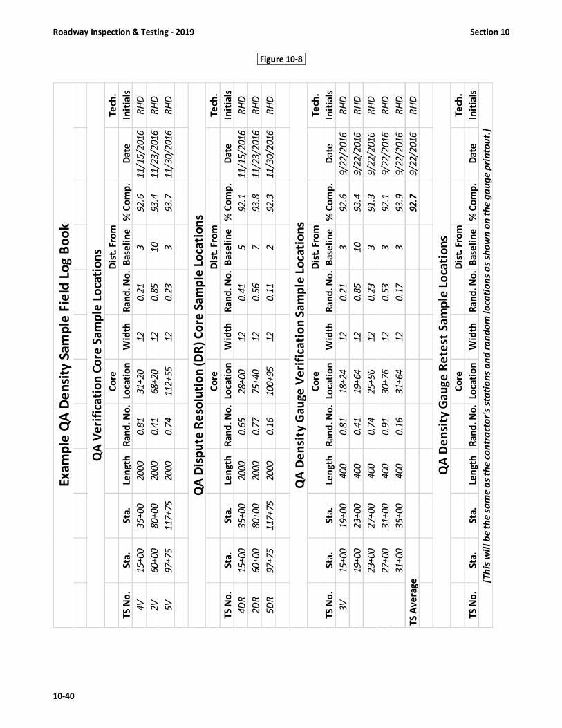
Roadway Inspection & Testing - 2019 Section 10
10-40
Figure 10-8-
Co
reD
ist.
Fro
mT
ech
.
TS
No
.S
ta.
Sta
.Le
ng
thR
an
d.
No
.Lo
cati
on
Wid
thR
an
d.
No
.B
ase
lin
e%
Co
mp
.D
ate
Init
ials
4V
15
+0
03
5+
00
20
00
0.8
13
1+
20
12
0.2
13
92
.61
1/1
5/2
01
6R
HD
2V
60
+0
08
0+
00
20
00
0.4
16
8+
20
12
0.8
51
09
3.4
11
/23
/20
16
RH
D
5V
97
+7
51
17
+7
52
00
00
.74
11
2+
55
12
0.2
33
93
.71
1/3
0/2
01
6R
HD
Co
reD
ist.
Fro
mT
ech
.
TS
No
.S
ta.
Sta
.Le
ng
thR
an
d.
No
.Lo
cati
on
Wid
thR
an
d.
No
.B
ase
lin
e%
Co
mp
.D
ate
Init
ials
4D
R1
5+
00
35
+0
02
00
00
.65
28
+0
01
20
.41
59
2.1
11
/15
/20
16
RH
D
2D
R6
0+
00
80
+0
02
00
00
.77
75
+4
01
20
.56
79
3.8
11
/23
/20
16
RH
D
5D
R9
7+
75
11
7+
75
20
00
0.1
61
00
+9
51
20
.11
29
2.3
11
/30
/20
16
RH
D
Co
reD
ist.
Fro
mT
ech
.
TS
No
.S
ta.
Sta
.Le
ng
thR
an
d.
No
.Lo
cati
on
Wid
thR
an
d.
No
.B
ase
lin
e%
Co
mp
.D
ate
Init
ials
3V
15
+0
01
9+
00
40
00
.81
18
+2
41
20
.21
39
2.6
9/2
2/2
01
6R
HD
19
+0
02
3+
00
40
00
.41
19
+6
41
20
.85
10
93
.49
/22
/20
16
RH
D
23
+0
02
7+
00
40
00
.74
25
+9
61
20
.23
39
1.3
9/2
2/2
01
6R
HD
27
+0
03
1+
00
40
00
.91
30
+7
61
20
.53
39
2.1
9/2
2/2
01
6R
HD
31
+0
03
5+
00
40
00
.16
31
+6
41
20
.17
39
3.9
9/2
2/2
01
6R
HD
TS
Av
era
ge
92
.79
/22
/20
16
RH
D
Co
reD
ist.
Fro
mT
ech
.
TS
No
.S
ta.
Sta
.Le
ng
thR
an
d.
No
.Lo
cati
on
Wid
thR
an
d.
No
.B
ase
lin
e%
Co
mp
.D
ate
Init
ials
[Th
is w
ill
be
th
e s
am
e a
s th
e c
on
tra
cto
r's
sta
tio
ns
an
d r
an
do
m l
oca
tio
ns
as
sho
wn
on
th
e g
au
ge
pri
nto
ut.
]
QA
Ve
rifi
cati
on
Co
re S
am
ple
Lo
cati
on
s
Ex
am
ple
QA
De
nsi
ty S
am
ple
Fie
ld L
og
Bo
ok
QA
De
nsi
ty G
au
ge
Ve
rifi
cati
on
Sa
mp
le L
oca
tio
ns
QA
De
nsi
ty G
au
ge
Re
test
Sa
mp
le L
oca
tio
ns
QA
Dis
pu
te R
eso
luti
on
(D
R)
Co
re S
am
ple
Lo
cati
on
s

Section 10 Roadway Inspection & Testing – 2019
10-41
10.6 CORE SAMPLE DENSITY QUALITY CONTROL (QC)
10.6.1 Core Sample Density Control - General
Core sample density control procedures shall be in accordance with this Manual. The Contractor is required to
furnish a certified QMS Roadway technician with each paving operation. The technician present with each paving operation
is responsible for monitoring all paving operations and directly supervising all quality control processes and activities related
to that operation.
10.6.2 Core Sample QC Control Strip Requirements and Procedures
When core sample density control is being utilized, an initial control strip at the beginning of each JMF and contract
is not required but is recommended for establishing rolling patterns to achieve the necessary compactive effort. Core
sample control strips will be required if production and placement is being performed under limited production procedures
due to failing densities. See "Limited Production Procedures" later in this section for details.
Frequency of Control Strips
1. Control strips are only required when the Contractor is proceeding on a limited production basis due to failing
densities. Limited Production consists of a 300-foot control strip plus 100-foot of pavement at the beginning and
end of the control strip. This 500 foot control strip is considered a separate lot.
2. In addition, the Engineer may require control strips anytime, as deemed necessary.
10.6.3 Numbering of Core Sample Control Strips and Core Samples
A. Control Strip
Control strips, if required, for a given contract shall be numbered consecutively by mix type, regardless of plant
furnishing mix. However, if a control strip is constructed from mix out of a second plant, the control strip number will be
followed by the suffix A; if out of a third plant then the control strip number would be followed by a suffix B, etc.
For example: 1st plant Control Strip would be 1, 2, 3;
2nd plant Control Strip would be 4A, 5A, 6A;
3rd plant Control Strip would be 7B, 8B, 9B, etc.
Each mix type will have a separate series of control strip numbers. Recycled mixes will not be considered a different
mix type and will carry the same series of consecutive numbers. Both passing and failing control strips will be numbered
and reported to the Engineer.
B. Control Strip Core Samples
QC Control Strip core samples will be numbered consecutively for each mix type being produced each day, except
will carry a suffix of QC, regardless of the plant producing the mix. In addition to being marked with the number, the core
sample should be marked with the date and mix type.
First Crew:
I19.0C 1st Control Strip: 1QC, 2QC, 3QC, 4QC, 5QC;
2nd Control Strip: 6QC, 7QC, 8QC, 9QC, 10QC
S9.5B 1st Control Strip: 1QC, 2QC, 3QC, 4QC, 5QC;
2nd Control Strip: 6QC, 7QC, 8QC, 9QC, 10QC
Second Crew:
I19.0C 1st Control Strip: 1QCA, 2QCA, 3QCA, 4QCA, 5QCA;
2nd Control Strip: 6QCA, 7QCA, 8QCA, 9QCA, 10QCA
S9.5B 1st Control Strip: 1QCA, 2QCA, 3QCA, 4QCA, 5QCA;
2nd Control Strip: 6QCA, 7QCA, 8QCA, 9QCA, 10QCA
If a third crew is used the consecutive numbers will continue with a suffix “B”

Roadway Inspection & Testing - 2019 Section 10
10-42
10.6.4 Construction of Core Sample Control Strips (QC Procedures)
To establish a control strip, asphalt shall be placed on a section of roadway approximately 300 feet in length. The
width shall be equal to the lay-down width of the paver. The material should be of a depth equivalent to the layer depth
shown in the plans or required by the Specifications. The Engineer may determine that the travel lane control strip is
representative of the shoulders and that the control strip may be used to determine the required density for the shoulders.
If shoulder control strips are constructed, they should be constructed to the full shoulder width and the depth shown on
the plans.
Since the control strip will assist in establishing the correct rolling pattern to obtain the specified density, it is very
important that the compaction equipment used on the control strip is operating properly. Reference should be made to the
applicable sections of the Specifications for minimum equipment requirements.
In order to achieve a complete and uniform coverage, the compactive effort shall consist of roller passes made
over the entire control strip surface. Breakdown rolling shall be performed at the maximum temperature at which the mix
will support the rollers without moving horizontally. The breakdown roller should normally be operated with the drive
wheel nearest the paver. The contractor will be responsible for carrying out the compaction operation in such a manner as
to obtain the required density uniformly over the entire control strip. The compaction rolling shall be completed prior to
the mixture cooling below a workable temperature.
To further assure complete and uniform coverage, the compactive effort shall consist of individual roller passes
made over the entire control strip surface. Each coverage should be completed before beginning the next. The QMS
Certified Roadway technician should observe the rolling operation to ensure that the control strip is rolled uniformly.
Core Samples from Control Strips shall be taken as shown below: (see Fig. 10-9)
1. A minimum of 5 core samples shall be placed in a control strip.
2. Core samples in the control strip shall be placed a distance of 50 feet apart.
3. Core samples shall be located at random across the width of the mat.

Section 10 Roadway Inspection & Testing – 2019
10-43
Figure 10-9 QC/QA Core Density Control Strip Procedure
5 Cores (5 random locations) will be taken within the 300’ control strip.
The 5 Core Samples will be taken at 50’ intervals in the longitudinal direction and at random locations transversely
across the width of the mat, but not less than one foot from the edge of pavement.
Core Control strips will only
be required when operating
under limited production
unless otherwise directed by
the Engineer.
QC shall confirm with the QA
Roadway Technician on when
and where the control strips
will be placed.
The 500 feet of pavement that
includes the control strip will
be considered a lot. The
average density of five control
strip cores will be used as the
density result for acceptance
of that lot.
Limited Production
consists of a 300-foot
Control Strip plus 100 feet
of pavement at the
beginning and end of the
Control Strip.
300-foot
Control
Strip
= Core Sample
(5 cores per control strip)
10’
0+00
1+00
4+00
5+00
300’
End Control Strip
End Limited Production
Begin Control Strip
4QC
3QC
1QC
5QC
2QC

Roadway Inspection & Testing - 2019 Section 10
10-44
10.6.5 Determination of QC Core Sample Control Strip Density
As stated previously, core sample control strips are only required when the Contractor is proceeding on a limited
production basis due to failing densities. After the Contractor has completed compaction of the control strip, cores samples
will be obtained as outlined above. The bulk specific gravity of each core will be obtained and compared to the maximum
specific gravity for the mix in accordance with Section 7.15.
If the average density of the 5 core samples (Gmb / Gmm) is equal to or greater than the specified density for the
mix, the control strip will be considered acceptable and paving may continue. If the average density of the 5 core samples
(Gmb / Gmm) fails to meet the specified density of the mix, then a new control strip should be immediately constructed. If
two control strips have been placed under limited production without achieving satisfactory density results, the Contractor
shall cease production of that mix type until such time as the cause of the failing test results can be determined. Unless
otherwise approved, the Contractor will not be allowed to produce this mix type on the contract until evidence is provided
that density can be obtained.
10.6.6 Establishment of QC Core Sample Test Sections
Any pavement placed which requires density testing in accordance with Section 10.3, will be divided into test
sections for density testing. Test sections shall be 2000 linear feet, or fraction thereof, of the paver laydown width, except
for intersections as noted below. Do not divide full test sections consisting of 2000 LF, unless otherwise approved by the
Engineer. As an exception, when a day’s production is less than 6,000 linear feet of laydown width, the total length paved
may be divided into 3 equal test sections, provided that core sample locations have not already been established.
If the fraction remaining is less than 100 linear feet, it is recommended that the density be represented by the
results of the previous section provided approved compaction equipment and procedures are used. If the remaining
fraction is 100 linear feet or more it will be considered a separate test section and shall be accordingly sampled and tested.
See Section 10.3.3 for “lot” definition and density acceptance.
If a control strip is constructed to establish the rolling pattern, the material used in a test section should be the
same type of material used in the applicable control strip and should be from the same source. The depth of a test section
should be equal (±1/2 inch) to that of the control strip previously constructed for use with the test section involved except
in cases where roadway control strips are used to determine required density for shoulder material.
Cored samples of the compacted pavement shall be taken at random locations from the full depth of the course.
Form QC-5 shall be used to determine the random location of each core (See example in Section 10.6.7). The samples shall
be taken no later than the beginning of the next production day, not to exceed 3 calendar days. The Contractor may elect
to cool the pavement layers by approved artificial methods to allow cutting the core samples as quickly as possible. No
compensation will be made for the costs of artificial cooling.
10.6.7 Determining Random Sample Locations for QC Core Sample Density Testing
Form QC-5 and tables of random numbers shall be used to randomly locate density test sites in order to avoid
repetition. The following Random Sampling Procedures and Random Sample Number Tables shall be used to locate both
density gauge and core sample locations within the normal density test sections. Control strip core samples are randomly
located transversely, but not longitudinally since these are required to be spaced 50 feet apart within the control strip. The
test section random sample locations shall be determined prior to beginning each test section and shall be documented on
Form QC-5. The Contractor’s QC technician should maintain a copy of this form and is also required to furnish a copy to the
Department’s QA roadway technician no later than the end of that production day. No other method of obtaining random
numbers for the location of either type density samples is acceptable. While the following procedures generally apply to
determining random locations for either density gauge or core sample density control, the example given applies primarily
to core sample control. The QMS Density Gauge Operator’s Manual should be consulted for a detailed example of locating
density gauge test sites.
Note: ASTM D3665 will be the only acceptable method used to produce random numbers for the QC-5 Form with the
following stipulations. Random numbers in Table 10-2 are to be used to calculate density test locations and are
to be used consecutively regardless of the mix type. The starting point will always be the upper left corner of
the random number table and the progression will be down the numbers in that column. Once all five hundred
numbers in a column have been used, the progression will be to the top of the next column and the process
repeated. As random numbers are used from the table, each used random number shall be lined through (not
obliterated) to show that they have been used. When ASTM D3665 is used, the following additional rules will
also apply. The same random numbers table will be used for all mix types per calendar year. If all random

Section 10 Roadway Inspection & Testing – 2019
10-45
numbers in Table 10-2 are used prior to the end of the calendar year, this process will begin anew and continue
through the end of that same calendar year.
The following are step-by-step instructions of how to locate the random test sites for five test sections. A
completed QC-5 form (Fig. 10-10) containing this example follows these instructions.
Note: QC-5 form shall be completed by either the contractor’s certified roadway technician or density gauge operator
1. Determine the test section length, control section length, or length in question and the number of sample locations
required by referring to the appropriate specification or procedures. Each test section length is 2000 feet or portion
thereof.
2. Determine the random sample numbers by referring to Table 10-2. Using the appropriate four digit random number
that has been selected, place a decimal in front of the first two digits. Going down the column in the same manner,
repeat this process using the next random sample numbers until the required number of locations has been
determined. In the example shown below, refer to the first column of four digits, use the first two digits which are 80.
By placing a decimal in front of these two digits, it becomes .80. Going down the column in the same manner, the next
four random sample numbers are .45, .18, .76, and .25.
3. Multiply each random sample number by the length of the test sections determined in #1 above.
In this example, a total of 9125 LF was paved. By dividing this length by 2000 it is determined that four full and one
partial test sections are required for this length of paving.
2000 LF X 4 full test sections = 8000 LF & 1125 LF (9125 LF total – 8000) for a partial test section.
Therefore: 2000 2000 2000 2000 1125
x .80 x .45 x .18 x .76 x .25
1600 900 360 1520 281
4. Add the distances determined in #3 to the beginning stations of each test section.
For this example, the beginning station of the 1st test section will be 0+00.
0+00 20+00 40+00 60+00 80+00
+ 16+00 + 9+00 + 3+60 + 15+20 + 2+81
16+00 29+00 43+60 75+20 82+81
5. Again referring to the same random sample numbers from Table 10-2 used in #2 above, determine a second set of
random sample numbers to be used in determining distances from the reference edge of the test sections. To do this,
place a decimal in front of the second two digits in each of the numbers and record. These random numbers become
.45, .53, .41, .10, and .46.
6. Multiply each random sample number determined in #5 by the width of the test section.
Calculate to the nearest whole number. In this example, the width is 12 feet.
Therefore: 12 12 12 12 12
x .45 x .53 x .41 x .10 x .46
5.40 (5 ft.) 6.36 (6 ft.) 4.92 (5 ft.) 1.20 (1 ft.) 5.52 (6 ft.)
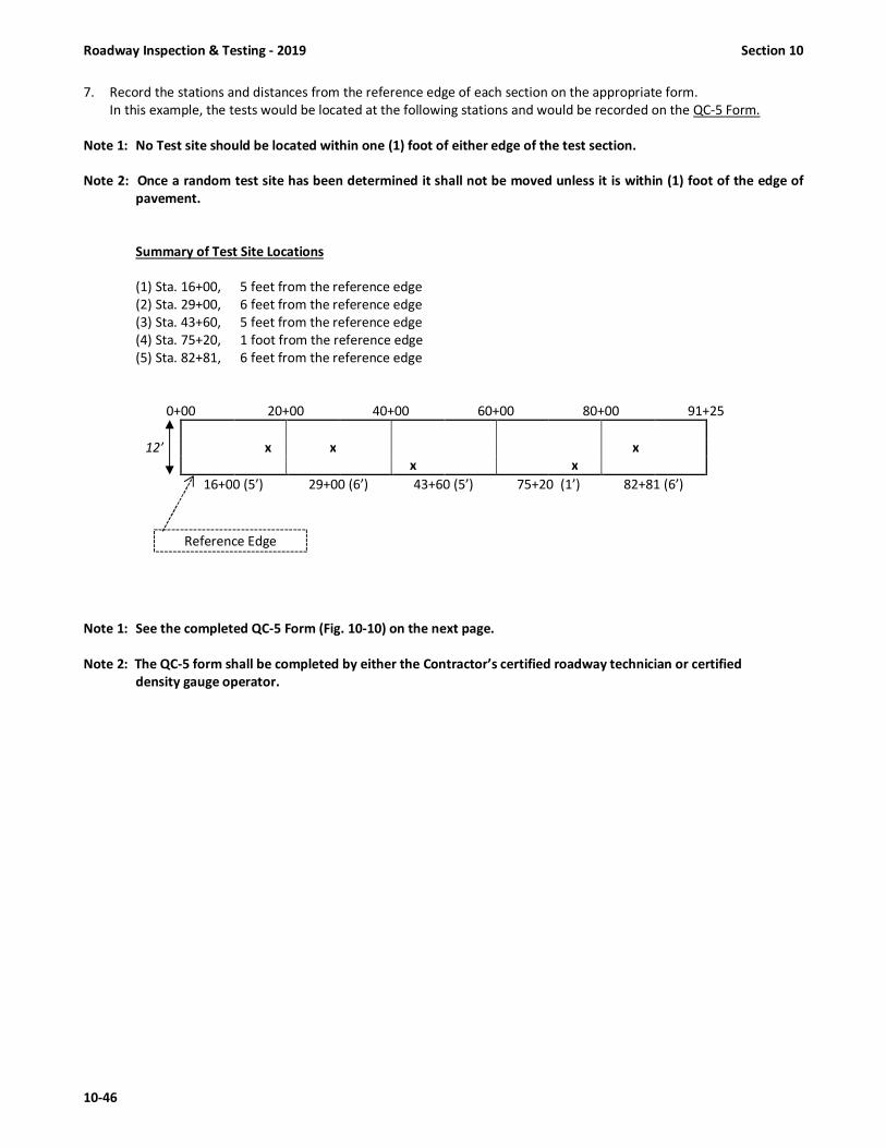
Roadway Inspection & Testing - 2019 Section 10
10-46
7. Record the stations and distances from the reference edge of each section on the appropriate form.
In this example, the tests would be located at the following stations and would be recorded on the QC-5 Form.
Note 1: No Test site should be located within one (1) foot of either edge of the test section.
Note 2: Once a random test site has been determined it shall not be moved unless it is within (1) foot of the edge of
pavement.
Summary of Test Site Locations
(1) Sta. 16+00, 5 feet from the reference edge
(2) Sta. 29+00, 6 feet from the reference edge
(3) Sta. 43+60, 5 feet from the reference edge
(4) Sta. 75+20, 1 foot from the reference edge
(5) Sta. 82+81, 6 feet from the reference edge
0+00 20+00 40+00 60+00 80+00 91+25
12’ x x x
x x
16+00 (5’) 29+00 (6’) 43+60 (5’) 75+20 (1’) 82+81 (6’)
Note 1: See the completed QC-5 Form (Fig. 10-10) on the next page.
Note 2: The QC-5 form shall be completed by either the Contractor’s certified roadway technician or certified
density gauge operator.
Reference Edge

Section 10 Roadway Inspection & Testing – 2019
10-47
Figure 10-10
QC
-5 R
ev.
Rev
. 1
0/
20
16
PR
OJE
CT
NO
. _
__
__
__
__
__
__
__
__
__
__
MA
P /
RT
. N
O.
__
__
__
__
__
__
__
__
__
_C
ON
TR
AC
TO
R:
__
__
__
__
__
__
__
__
_D
AT
E P
LAC
ED
: _
__
__
__
__
__
__
__
__
BA
SE
TY
PE
: _
__
__
__
__
__
__
__
__
__
__
LAN
E D
ES
C.:
__
__
__
__
__
__
__
__
__
__
_B
AS
ELI
NE
: _
__
__
__
__
__
__
__
__
__
__
PLA
NT
LO
CA
TIO
N:_
__
__
__
__
__
__
__
TY
PE
MIX
: _
__
__
__
__
__
__
__
__
__
__
JMF
NO
.: _
__
__
__
__
__
__
__
__
__
__
RE
S.
EN
GR
. :
__
__
__
__
__
__
__
__
__
__
_
CO
RE #
TE
ST
SE
CT
ION
Te
st
BE
GIN
NIN
GD
ist.
Fro
mC
OR
ES
Se
cti
on
Le
ng
thW
idth
Len
gth
Wid
thLe
ng
thW
idth
ST
AT
ION
#Sta
tio
nB
ase
lin
eS
AM
PLE
PE
RC
EN
T
No
.(A
)(B
)(C
)(D
)(E
= A
X C
)(F
= B
X D
)(G
)(G
+ E
)(F
)T
HIC
KN
ES
SC
OM
PA
CT
ION
11
2000
12 '
0.8
00.4
51600
5.4
00+00
16+00
51.5
"93.6
22
2000
12 '
0.4
50.5
3900
6.3
620+00
29+00
61.6
"92.8
33
2000
12 '
0.1
80.4
1360
4.9
240+00
43+60
51.4
"93.1
44
2000
12 '
0.7
60.1
01520
1.2
060+00
75+20
11.5
"93.5
55
1125
12 '
0.2
50.4
6281
5.5
280+00
82+81
61.5
"92.4
92.4
CO
NS
TRU
CTI
ON
CA
TEG
OR
Y:
"N
ew
"�
"O
the
r"
Pa
ss
es
SE
E S
EC
TIO
N 1
0.3
.3 O
F T
HE
LA
TE
ST
VE
RS
ION
OF
TH
E
"QM
S M
AN
UA
L" F
OR
GU
IDE
LIN
ES
FO
R D
ET
ER
MIN
ING
TH
E
CO
NS
TR
UC
TIO
N C
AT
EG
OR
Y F
OR
AC
CE
PT
AN
CE
PU
RP
OS
ES
.Fa
ils
**N
OT
E: B
Y P
RO
VID
ING
TH
IS D
AT
A U
ND
ER M
Y S
IGN
AT
UR
E A
ND
HiC
AM
S C
ER
TIF
ICA
TIO
N N
UM
BE
R,
I AT
TEST
TO
TH
E A
CC
UR
AC
Y A
ND
VA
LID
ITY
OF
TH
E D
ATA
CO
NT
AIN
ED
ON
TH
IS F
OR
M A
ND
CE
RTI
FY T
HA
T N
O D
ELI
BE
RA
TE
MIS
REP
RES
ENTA
TIO
N O
F T
EST
RE
SUL
TS, I
N A
NY
MA
NN
ER
, H
AS
OC
CU
RR
ED
.
**
CE
RT
IFIE
D Q
C L
AB
TE
CH
NIC
IAN
'S S
IGN
AT
UR
E
NO
RT
H C
AR
OLI
NA
DE
PA
RT
ME
NT
OF
TR
AN
SP
OR
TA
TIO
N
DA
ILY
CO
RE
LO
CA
TIO
N &
LO
T S
UM
MA
RY
TEST
SEC
TIO
NR
AN
DO
M #
RA
ND
# x
LE
NG
. /
WID
TH
CO
RE
LO
CA
TIO
N
Lot
Av
era
ge
�
**
CE
RT
IFIE
D Q
C R
OA
DW
AY
TE
CH
NIC
IAN
'S S
IGN
AT
UR
E
**
PR
INT
CE
RT
IFIE
D Q
C R
OA
DW
AY
TE
CH
NIC
IAN
'S N
AM
E /
W H
iCA
MS
#
**
PR
INT
CE
RT
IFIE
D Q
C L
AB
TE
CH
NIC
IAN
'S N
AM
E /
W H
iCA
MS
#
03/2
2/2
018
Quality
Pavi
ng
US 13
8.1
234567
RS 9.5
C17-0
610-1
51
Payfo
re D
aMix
Rt. EOP
Eve
rywhere
(New)RI 19.0
CNBL R
t.
QC
Roa
dtec
h
RD
1-58
8
QC R
oadte
ch
QC Labtech P1S-422
Q. C. Labtech
Q. C. Labtech
Q. C. Labtech
Q. C. Labtech

Roadway Inspection & Testing - 2019 Section 10
10-48
10.6.8 Testing a Core Sample Test Section (QC)
All asphalt mixes shall be compacted to a minimum of 92.0 percent of the maximum specific gravity (Gmm), except
for S9.5B and S4.75A mixes, which shall be 90.0 and 85.0 percent of maximum specific gravity (Gmm), respectively. The
density of each test section will be determined by comparing the bulk specific gravity of the core samples, which were
obtained at random locations, to the maximum specific gravity (Gmb / Gmm) of mix placed in accordance with Section 7.12.
Density compliance for core samples will be initially determined by use of the maximum specific gravity obtained during
initial mix verification. Once sampling and testing of the mix occurs, the average maximum specific gravity (Gmm) for the
number of tests performed will be utilized until a moving average of the last four maximum specific gravities are obtained.
Once a moving average of four tests is obtained it will be used from that point forward.
If the core sample density results for each test section fails to meet the Specifications requirements detailed above,
and in Table 610-7, the test section will fail and may require corrective action.
The density results from all Test Section constructed during a day’s production will be averaged to establish a lot. (See
Section 10.3.3 for the determination of lots). All test sections regardless of length will have a minimum of (1) one random
core taken. In addition, for any day's production, each lot shall have a minimum of (3) three core samples taken. As an
exception, when a day’s production is less than 6,000 linear feet of laydown width, the total length paved may be divided
into 3 equal test sections, provided that core sample locations have not already been established.
10.6.9 Numbering Quality Control (QC) Core Samples
A. Quality Control Cores will be numbered consecutively for each mix type being produced each day. QC core samples
numbers will start over with #1 each day for each mix type. In addition to being marked with the number, the core sample
should be marked with the date and mix type.
Example 1st Day: I19.0C: 1, 2, 3, etc. S9.5C: 1, 2, 3, etc.
2nd Day: I19.0C: 1, 2, 3, etc. S9.5C: 1, 2, 3, etc.
B. If the Contractor has more than one paving operation on the same project, the second crew will have a separate
series of consecutive numbers followed by a suffix “A”.
Example 1st Crew: I19.0C: 1, 2, 3, etc. S9.5C: 1, 2, 3, etc.
2nd Crew: I19.0C: 1A, 2A, 3A, etc. S9.5C: 1A, 2A, 3A, etc.
3rd Crew: I19.0C: 1B, 2B, 3B, etc. S9.5C: 1B, 2B, 3B, etc.
C. If a second or third plant is used on the same day’s operation, the numbers will continue consecutively with the
appropriate suffix, if a suffix is applicable.
Example 1st Plant: I19.0C: 1, 2, 3 S9.5C: 1, 2, 3, etc.
2nd Plant: I19.0C: 4, 5, 6, etc. S9.5C: 1A, 2A, 3A, etc.
10.6.10 Checking QC Core Samples
The Contractor may elect to take check core samples for any of the reasons below:
1. When cored sample control is being utilized and a core sample(s) is more than 2.0 percent below the average
of all core samples from the same lot, that core(s) sample may be checked.
2. When a control strip fails and a core sample(s) is more than 2.0 percent below the average of the control strip,
that core(s) may be checked.
For each core sample that is in question, there shall be 3 check samples taken: 1 adjacent (8 in. center-to-center
transversely) to the initial sample and 2 cores (10 feet on either side) longitudinally from the initial sample (see Fig. 10-11).
The results of these 3 check samples will be averaged and this average shall be used instead of the initial core results in
question. The initial core sample results will not be used if check samples are taken. Check samples must be taken within
2 calendar days of the date of the initial sample. Only 1 set of check samples per sample location will be allowed. If full
depth cores are necessary at these check sample locations, separation of the layer to be tested will be the responsibility of
the Contractor. All check samples shall be taken in the presence of a representative of the Engineer and transported by the
Contractor to the appropriate QC Lab. Core sample checking procedures and requirements are as follows:

Section 10 Roadway Inspection & Testing – 2019
10-49
(Only allowed if core result is below the lot average by more than 2.0%)
- Contractor’s option
- Must be taken within 2 calendar days of original sample
- Only 1 set of check samples per original core
- Contractor’s responsibility to separate layers of check samples
- Must be taken in presence DOT representative
Figure 10-11
Check Sample Procedure
10.6.11 Numbering Quality Control (QC) Check Core Samples
1. Check samples are allowed adjacent to the original core and 10 feet longitudinally each side of the original core.
2. All check samples will carry the same base number as the original core sample followed by a
C1, C2, C3 series of suffixes.
Example : If core number 8 is in question, the check core samples will be:
8C1 (10’ down station), 8C2 (adjacent), and 8C3 (10’ up station).
10.6.12 Reporting Core Sample Control (QC) Test Sections (Form QC-5)
Once random locations have been determined, a core sample will be taken at each location. Sample locations,
sample results in percent compaction, lot average, and other appropriate information shall be recorded on Form QC-5 (see
Fig. 10-10) The form shall be initiated by the Contractor’s QC technician by completing sample location information at the
paving site. The QC samples and Form QC-5 will be taken to the appropriate QC Lab by QC personnel. Once the compaction
results are determined, the QC Plant technician will complete the thickness and compaction information on the form. The
original form is returned to the DOT’s Roadway technician as soon as the test results are known. The DOT’s Roadway
technician will attach the form to the Daily Roadway Report (M&T 605) and forward to the Resident Engineer.
Original Sample #8 = 89.3%
Average of 3 check samples (88.6%)
shall replace original sample results
(89.3%) for payment.
Check Samples
8C1 = 88.4%
8C2 = 88.8%
8C3 = 88.7%
Avg. = 88.6%
Longitudinal Direction
8” center to center
8C1
8C2
8C3
Original
Core #8
10 ft. 10 ft.
down station up station

Roadway Inspection & Testing - 2019 Section 10
10-50
Figure 10-12
Determining Number of Test Sections Cored Density Control
• Contractor’s Responsibility, subject to DOT roadway technician's concurrence.
• Done daily to assure the minimum testing frequency is being met.
• Contractor must advise the Roadway Inspector.
All test sections for core sample
density will be a maximum of 2000
feet or fraction thereof per day.
All test sections, regardless of
length will have a minimum of 1
random core taken.
In addition, any day’s production
shall have a minimum of 3 core
samples taken.
4800 linear feet , 10 feet wide
4800 LF ÷ 2000 LF = 2.4
Therefore,
3 cores required, minimum.
10’
Beginning any day’s
production and / or
1st test section for
any lot.
10+00
58+00
50+00
30+00
2000’
2000’
800’

Section 10 Roadway Inspection & Testing – 2019
10-51
10.7 CORE SAMPLE DENSITY QUALITY ASSURANCE (QA)
Quality Assurance is a process of sampling and testing the Contractor’s product and monitoring his operations to
confirm that the Quality Control results are adequate and accurate. This process is normally performed by Department
personnel. Quality Assurance testing shall be accomplished in the following ways:
1. Conducting verification sampling and testing on test sections at random locations within the same QC test
sections at a frequency of 10% of the required QC sampling and testing frequency. This minimum Department
sampling frequency should be based on mix type.
1) Retesting randomly selected quality control core samples at a frequency equal to or greater than 10% of the
total Quality Control core samples per mix type, per calendar year, for each plant;
2) Periodically observing sampling and testing performed by the Contractor;
3) By periodically directing the recalculation of random numbers for the quality control core test locations. The
original QC test locations maybe tested by QA and evaluated as verification tests;
4) By any combination of the above.
Verification core samples shall be taken in the presence of a DOT technician, and either delivered directly to the
appropriate M&T Lab by a DOT technician or placed in a sealed container and delivered to the Contractor’s QC Lab for
pickup by Department personnel. Results of all density quality assurance tests will be provided to the Contractor within 3
working days after the samples have been obtained by Department personnel.
Differences between the Contractor's quality control and the Department's quality assurance test results will be
considered acceptable if within the following limits.
Test Acceptable Limits of Precision
Retest of QC Core Sample ± 1.2% (percent compaction)
QA Verification Core Samples* ± 2.0 % (percent compaction)
*Note: Verification tests will be compared to QC results from the same test section.
In the event test results are outside the above acceptable limits of precision or the quality assurance or verification
test results are below the minimum specification requirements, the Engineer will immediately investigate the reason for
the difference. If the potential for a pavement failure is present, the Engineer may suspend production as stated in
Article 108-7 of the Standard Specifications while the investigation is in progress.
The Engineer's investigation may include checking of the Contractor's testing equipment, comparison testing of
other retained quality control samples, or additional core sample testing of the roadway pavement in question. If additional
core samples are necessary to resolve the difference, the Contractor shall core these samples at the direction of the
Engineer and these will be tested jointly by the Contractor's quality control and Department's quality assurance personnel.
If the reason for the difference cannot be determined, payment for the mix in question will be determined in accordance
with Article 105-3 of the Standard Specifications. If the reason for the difference is determined to be an error or other
discrepancy in the quality control test results, the applicable quality assurance test results will be used to determine
compliance with the Specification density requirements.
10.7.1 Core Sample Test Section Procedures
Core samples to be tested at a Department laboratory will be taken in the presence of a DOT technician, and
either delivered directly to the appropriate M&T Lab by a DOT technician or delivered to the Contractor’s QC Lab for pickup
by Department personnel. If the cores are delivered to the QC lab for later pick-up, they should be placed inside a six (6)
inch diameter tin or plastic cylinder and then placed into a cloth sample bag. The sample bag should then be sealed with a
metal tag. These sample cylinders, sample bags and metal tags should be obtained from the M&T Lab. If core samples are
not delivered to the M&T Lab in accordance with either of the above methods, the samples will be discarded and not tested.
10.7.2 Quality Assurance (QA) Core Sample Verification & Dispute Resolution Process
Verification sampling and testing is an integral part of the Department's quality assurance process. When cutting
Verification Cores, a 2nd core will also be cut and designated as a Dispute Resolution core that may be used in the event
the Verification core fails to compare within limits of precision to the QC sample. The DR sample will be cut from the same
test section as the Verification sample at a separate and random location. This independent sampling and testing is
performed by QA personnel to help assure that QC density results are accurate. All verification sample numbers and random
locations will be documented in a field sample book by the QA Density Gauge operator (see example log book Fig. 10-8). It

Roadway Inspection & Testing - 2019 Section 10
10-52
is very important that all personnel involved with the QMS density sampling and testing procedures of asphalt pavements
be knowledgeable of these requirements and guidelines.
If the test results for the verification core and QC core within a test section are not within the required limits of
precision the following steps should be taken to determine the acceptability of the pavement:
1. The Engineer will determine any extenuating circumstances such as poor subgrade issues, leveling, or wedging and
may accept failing test sections in accordance with Article 105-3. If it is determined that the area the Verification
core was taken is not representative of the entire test section, the QC density results will be used for acceptance.
If the Engineer determines extenuating circumstances exist then that should be documented and the QC results
shall be used for acceptance.
2. If the Engineer determines extenuating circumstances do not exist then:
The Verification core and original QC cores from the failing test section will be jointly re-tested. At the same time,
Department personnel will take possession of all original QC cores from that day’s lot. If the re-test of the original
QC and V cores are within limits of precision, the original QC test result will be used for acceptance. No further re-
testing will be required if above is met.
3. After jointly retesting, if the original Verification test result is still not within the limits of precision when compared
to the QC result, the Dispute Resolution core from the Verification test section and QC cores from the remaining
test sections of that day’s lot will be tested at the Central or another M&T Lab.
a) The DR test result will be used in lieu of the original QC result for acceptance of that test section.
b) If the re-tests of the original QC cores from the remaining test sections are within limits of precision, the
original QC results will be used for the remaining test sections.
c) If the QC cores from one or more of the remaining test sections fail to meet the limits of precision, a DR core
will be taken from those test sections and tested at the Central or another M&T Lab. When required the DR
test result will be used in lieu of the QC result for the applicable test sections.
d) When complete with the dispute resolution process, the applicable QC or DR results from individual test
sections will be averaged to determine acceptance of the entire lot.
10.8 ACCEPTANCE OF DENSITY (DENSITY GAUGE AND/OR CORE SAMPLE CONTROL)
The Department will evaluate the asphalt pavement for density compliance after the asphalt mix has been placed
and compacted using the Contractor's quality control test results, the Department's quality assurance test results (including
verification samples), and by observation of the Contractor's total density quality control process. All asphalt mixes shall
be compacted to a minimum of 92.0 percent of the maximum specific gravity (Gmm), except for S9.5B and S4.75A mixes,
which shall be 90.0 and 85.0 percent of maximum specific gravity (Gmm), respectively.
The pavement will be accepted for density on a lot by lot basis. See Section 10.3.3 for the “Determination of Lots”.
A passing lot for density acceptance purposes is defined as a lot for which the average of all test sections meets minimum
specification requirements.
A failing lot for density acceptance purposes is defined as a lot for which the average of all test sections, and
portions thereof, fails to meet the minimum specification requirement. If additional density sampling and testing, beyond
the minimum requirement, is performed and additional test sections are thereby created, then all test results shall be
included in the lot average. A lot does not fail for acceptance purposes and cannot be penalized unless the average for that
lot fails to meet the minimum specification requirement. However, any portion of a lot that is obviously unacceptable in
the opinion of the Engineer will be rejected for use in the work and replaced with mix that meets the specification
requirements.

Section 10 Roadway Inspection & Testing – 2019
10-53
10.8.1 Pay Factor for Density
If the Engineer determines that a given lot of mix which falls in the “new” category does not meet the minimum
specification requirements but the work is determined to be reasonably acceptable and may remain in place, the lot may
be accepted at a reduced pay factor in accordance with the following formula. The reduced pay factor will apply only to
the mix unit price.
Reduced Pay Factor = 100 +f@gh���=i�����D − ��h�����i�����D2 F× 30j Where:
Actual Density = the lot average density, not to exceed 2.0% of the specified density
Specified Density = the density in Table 610-7 or as specified in the contract
Acceptance of all failing lots falling in the “other” category will be made under the provisions of Article 105-3 of
the Standard Specifications.
Any density lot not meeting the density requirements detailed in Table 610-7 will be evaluated for acceptance by
the Engineer. If the lot is determined to be reasonably acceptable, the mix will be paid at an adjusted contract price in
accordance with Article 105-3 of the Specifications. If the lot is determined not to be acceptable, the mix will be removed
and replaced with mix meeting and compacted to the requirement of the Standard Specifications.
A high frequency of asphalt plant mix or density deficiencies may result in future deficient asphalt being excluded
from acceptance at an adjusted contract unit price in accordance with Article 105-3. The Engineer shall document cases of
frequent deficiencies and provide in writing the details of deficiencies to the Contractor with copies to the Pavement
Construction Engineer and Asphalt Mix Design Engineer. Upon receipt of these details, the Contractor shall develop a plan
for corrective action and submit it to the Engineer in writing. Failure to satisfactorily correct repeated deficiencies may
result in future deficient asphalt being excluded from acceptance at an adjusted contract unit price in accordance with
Article 105-3. This acceptance process will apply to all asphalt produced or placed and will continue until the Engineer
determines a history of quality asphalt production and placement is reestablished.
Any reduction in pay due to failing densities will be in addition to any reduction in pay due to failing mix property
test results on the same mix. For example: If there is a 10% price reduction due to mix properties and a 30% reduction due
to failing densities, the total price reduction will be 40% or a pay factor of 60% that will be applied to the contract unit bid
price.
10.8.2 Small Quantities Density Acceptance Process
For individual structure replacements and projects having 1,500 linear feet or less of roadway pavement, a
modified density acceptance process shall be used.
This small quantities acceptance process will require core sample density control to be used. The pavement
meeting the requirements of this section will be included in the “other” construction category. Pavement in the “other”
construction category which fails to meet the minimum density specification requirements shall be accepted in accordance
with Article 105-3 of the Specifications.
A minimum of two (2) core samples per pavement layer per day will be required and shall be randomly located
according to the procedures of Section 10.6.7. However, if the project includes a structure (bridge, culvert, etc.) with asphalt
pavement on either side of the structure, the pavement shall be divided into two test sections (one test section on each
side of the structure). Then, a minimum of one (1) core sample per pavement layer will required from each test section.
No Verification or Dispute Resolution core samples are required for Small Quantities density acceptance.
The Contractor shall be responsible for cutting cores for testing by the Department. These Small Quantity (“SQ”)
core samples will be taken in the presence of a DOT technician, and uniquely numbered (SQ-1, SQ-2, etc.). The SQ cores
shall be delivered directly to the appropriate M&T Lab by either a DOT technician or a Contractor’s technician. In such cases
where the cores will not be in the Engineer’s possession during transport, the protocols of Section 10.7.1 for sealing and
identification shall be followed.
Testing shall be completed and test results reported to the Contractor within 3 calendar days of the core samples
being delivered to the M&T Lab. The Dispute Resolution process will be done by jointly re-testing of all cores at an agreed-
upon QMS laboratory.
For acceptance purposes, the results of the core samples will be averaged and compared to the minimum density
specification for that mix type.

Roadway Inspection & Testing - 2019 Section 10
10-54
Figure 10-13
QA-5 NORTH CAROLINA DEPARTMENT OF TRANSPORTATION 12-17-02
REPORT OF QUALITY ASSURANCE CORE SAMPLE DENSITY RESULTS
PRIME
PROJECT NO. 8.1234567 RESIDENT ENGINEER: I. B. DaMan CONTRACTOR: Quality Paving DIVISION: 1 PLANT LOCATION: Everywhere, NC
WITHIN LIMITS OF
PRECISION CORE
SAMPLE
NO.
DATE
PLACED
TYPE
MIX JMF NO.
MAP/
ROUTE
NUMBER
STATION
NUMBER
LANE
DESCRIPT.
QA CORE
RESULTS
QC CORE
RESULTS YES NO
6R 5/28 I19.0C 99-001-051 US 17 16+30 Lt. NBL
92.8 93.4 �
3V 5/29 S9.5C 04-121-151 US 17 21+45 Rt. NBL
94.1 93.8 �
4V 5/30 S9.5C 04-121-151 US 17 60+18 Lt. NBL
91.7 * 92.4 �
CODE: “R” = Retest of QC Sample “V” = Verification Sample
Rocky Road RD1 - 4273 **PRINT CERTIFIED QA ROADWAY TECHNICIAN’S NAME w/Hi CAMS #
R o c k y R o a d **CERTIFIED QA ROADWAY TECHNICIAN’S SIGNATURE
Distribution: 1. Original to Resident Engineer 2. FAX Copy to QC Lab 3. QC Lab to Forward Copy to NCDOT Roadway Technician
Libby Lab P1S - 5378 **PRINT CERTIFIED QA LAB TECHNICIAN’S NAME w/HiCAMS #
L i b b y L a b
**NOTE: BY PROVIDING THIS DATA UNDER MY SIGNATURE AND/OR HiCAMS CERTIFICATION NUMBER, I ATTEST TO THE ACCURACY AND VALIDITY OF THE DATA CONTAINED ON THIS FORM AND CERTIFY THAT NO DELIBERATE MISREPRESENTATION OF TEST RESULTS, IN ANY MANNER, HAS OCCURRED.
** CERTIFIED QA LAB TECHNICIAN’S SIGNATURE

Section 10 Roadway Inspection & Testing – 2019
10-55
10.9 LIMITED PRODUCTION PROCEDURES FOR DENSITY GAUGE AND CORE SAMPLE FAILURES
The Contractor shall operate on a limited production basis if, for the same mix type and contract, one of the following
items occurs (except as noted in the 1st paragraph below):
(1) Two consecutive failing lots, except on resurfacing*
(2) Three consecutive failing lots on resurfacing*.
(3) Two consecutive failing density gauge control strips.
*Resurfacing is defined as the first new uniform layer placed on an existing pavement.
As an exception to the above, pavement within each construction category (New and Other) as defined in Section
10.3.3, and pavement placed simultaneously by multiple paving operations will be evaluated independently for limited
production purposes.
Once the Contractor is placed on limited production he shall remain on limited production for that mix type
regardless of the plant or JMF. Recycled versions of the same mix will not be considered a different mix type. The Contractor
may elect to produce a different mix design of the same mix type but must begin under limited production procedures. As
an exception, the Engineer may grant approval to produce a different mix design of the same mix type if Quality Control
and Quality Assurance plant mix test indicate the failing densities are attributed to the mix problem(s) rather than
compaction related problems and limited production startup would not be required. The determination of whether a mix
problem exists at this time will be made by the Pavement Specialist. Should the Contractor elect to produce a different mix
design of the same mix type, all of the previous mix in question that has not been tested with a correlated target density
will be accepted based on the calculated target unless the Contractor elects to cut density acceptance cores.
Limited production is defined as the production, placement, and compaction of a sufficient quantity of mix to
construct a 300-foot control strip plus 100 feet of pavement adjacent to each end of the control strip.
The Contractor shall remain on limited production until such time as satisfactory density results are attained or
two consecutive control strips have been attempted without achieving acceptable density test results, whichever occurs
first. Should the Contractor fail to achieve satisfactory density at this point, production of that mix type shall cease until such
time as the cause of the failing density test results can be determined. Unless otherwise approved, the Contractor will be
required to place this mix type off the project limits for evaluation prior to the proceeding on the project.
When proceeding on limited production due to failing density for either density gauge or core control, the 500 feet
of pavement, which includes the control strip, will be considered a lot. The average density of the five control strip cores
will be used as the density result for acceptance of that lot in accordance with Article 610-14.
Quality control mix sampling and testing shall be performed at the frequencies detailed in Section 7.3, unless
placing mix on a limited production basis due to failing densities. When on limited production, a minimum of a partial test
series (including a new Maximum Specific Gravity test) shall be performed on the actual mix placed in each control strip.
When a mix sample is obtained in conjunction with a control strip, that sample will not substitute for the next randomly
scheduled QC mix sample for that tonnage increment, nor shall it be plotted on the control charts. However, all applicable
plant mix tests results shall be reported to the Department. The maximum specific gravity (Gmm) used to calculate percent compaction for the control strip placed shall be the
individual Gmm for the sample of mix taken from the mix incorporated into the control strip. If there is a Gmm change on the
Job Mix Formula in accordance Section 7.4.3, all moving averages shall be re-established. Subsequent QC mix samples will
be taken in accordance with normal random sampling procedures. When placing mix on a limited production basis, the
contractor’s QC plant personnel will notify roadway personnel from which truck the mix sample was taken. The notification
method will be at the Contractor’s option (radio, telephone, and note on load ticket, etc.) This load shall be included within
the 300-foot control strip.
If the Contractor does not operate by the limited production procedures as specified in the first paragraph of this
section, all applicable failing lots and mix produced thereafter will be considered unacceptable. This material shall be
removed and replaced with material which complies with the Specifications at no additional cost to the Department.
Payment will be made for the actual quantities of materials required to replace the removed quantities, not to exceed the
original amounts. The final in-place materials will be accepted in accordance with Article 105-3.

Roadway Inspection & Testing - 2019 Section 10
10-56
10.10 INDEPENDENT ASSURANCE (IA) SAMPLING & TESTING FOR DENSITY CONTROL
10.10.1 Density Gauge Correlation Program
It is the intent of this program to ensure continued competency of the personnel performing quality control and
quality assurance gauge density testing of asphalt pavements. The Materials & Tests technician is to observe and assess the
QC/QA personnel perform the test procedure, evaluate the testing equipment and record their observations on the
appropriate forms. All equipment utilized in the testing must be in good working order and the calibration should be current.
If the Materials & Tests technician observes the technician perform a testing procedure incorrectly the Materials & Tests
technician will note the incorrect procedure.
The Materials & Tests technician shall assess each QC and QA technician actively performing gauge density testing
at a minimum of once per year. Active is defined as the technician having tested at least five gauge density test sections
during the assessment cycle.
Once the Materials & Tests technician has observed the testing/sampling procedure, they will take a comparative
core sample from the gauge test site. This sample shall be sent to either the Central Asphalt Laboratory or the appropriate
M&T Regional Laboratory.
Any correlation that is greater than 3.0% shall be considered to be poor. All fair and poor ratings shall be
investigated in an attempt to determine the reason for the disparity.
10.10.2 Conventional Core Density Correlation Program
This program is designed to provide assurance of the on-going proficiency of the QC/QA Density program with
regards to conventional core testing procedures and equipment.
The Materials & Tests technician shall assess each QC and QA technician actively performing core testing at a
minimum of once per year. Active is defined as the technician having tested at least five gauge density test sections during
the assessment cycle. The core samples will be brought to the Materials and Tests Unit and comparatively tested for
density.
The QA and IA results shall be correlated according to the IAS Correlation Chart. Any correlation that is greater
than 0.06 shall be considered to be poor. All fair and poor ratings shall be investigated in an attempt to determine the
reason for the disparity.

Section 11 Pavement Smoothness/Rideability - 2019
11-1
SECTION 11 PAVEMENT SMOOTHNESS / RIDEABILITY
11.1 PAVEMENT SMOOTHNESS
Pavement smoothness is an important consideration for several reasons. Studies have indicated that the prime
factor that influences the user’s opinion of a road is longitudinal roughness. Rough riding pavements generate complaints
from motorists by providing uncomfortable ride, damaged vehicles, reduced travel speeds, and accelerating the wear of
the pavement structure itself. Many believe that pavement roughness is an indicator of overall quality of workmanship by
the Contractor. It is generally believed that if the Contractor provides a very smooth pavement, there is greater likelihood
that good quality workmanship has been provided throughout the many steps of roadway construction that span the
spectrum from subgrade preparation to rolling of the final surface layer. There is also a growing belief among pavement
engineers that smooth pavements not only provide a higher level of service but also last longer than otherwise equivalent
but initially rougher pavements. Because of these considerations, specifications have been developed in an effort to achieve
smoother pavements.
Roughness experienced by a roadway traveler is a function of pavement profile, vehicle speed, and various vehicle
parameters, including tire and suspension characteristics. A variation in any of these factors can make a road profile appear
either smooth or rough. From a passenger’s viewpoint, roughness can be defined as an undesirable combination of road
profile, vehicle parameters, and speed.
Pavement smoothness is adversely affected by a lack of uniformity in the paving operations, improper aggregate
gradations, variation in mix temperature, variation in paver speed, improper operation of trucks, poor joint-construction
practices, segregation, and improper rolling.
Stopping the paver can cause roughness in the pavement. Every time the paver stops, there is a possibility of the
screed leaving a mark on the surface of the mat. If the screed settles into the mix, it causes the automatic sensor to act as
if the paver has traveled into a depression. As the paver starts off, the screed lays a thicker mat. This continues until the
sensor recognizes the excessive thickness and decreases the slope of the screed. Then a dip is developed until the screed
levels out, approximately 30 feet from where the paver stopped.
Irregularities in the lower courses can usually be corrected by removing or adding material. In surface courses, the
entire affected area may need to be removed promptly and sufficient new material placed to form a true and even surface.
When the required smoothness is obtained on the first course or multi-layered pavements, the subsequent courses can
usually be placed uniformly by simply setting the paver for the thickness required and proper use and operation of the
automatic screed controls.
Rough pavements also result from changes in amounts of material introduced in front of the screed. If there is not
enough material in front of the screed, the screed will drop. If there is too much material in front of the screed, it will rise.
A uniform head of mix should be maintained at all times in front of the screed.
End of the load segregation, which is often times caused by emptying the paver hopper between loads, leaves a
rough pavement surface texture. An adequate quantity of mix should be maintained in the paver hopper at all times during
laydown operations to help prevent this problem.
11.1.1 Profile Testing
The importance of constructing a project to the plan profile and grade for driver safety and producing a smooth
pavement which meets or exceeds the testing tolerances cannot be overemphasized. Deviations from the acceptable
tolerances can result in expensive corrective actions and/or significant price adjustments. The methods of profile testing
utilized by NCDOT to determine specification compliance are as follows:
1) Article 610-12 of the Specifications requires that any location on the pavement selected by the Department and
all joints be checked using a 10-foot non-mobile straightedge and that the variation of the surface from the straightedge
shall not exceed 1/8 inch between any two contact points. This requirement applies to all layers of mix not just the final
surface. The 10-foot straightedge is furnished by the Contractor and must be used by both the Contractor and the DOT
technician to assure that the surface at joints and all other pavement surfaces meet this requirement. The paving operation
should not begin until this 10-foot straightedge is on hand at the paving site.
2) Article 610-13 of the Specifications requires that the finished pavement surface is tested using either an Inertial
Profiler (Option 1) or the North Carolina Hearne Straightedge (Option 2). The Contractor needs to submit in writing to the
Engineer the selected option for smoothness acceptance testing before any paving operations begin. If Option 1 is selected,
the Contractor shall furnish an Inertial profiler equipped with line laser technology to measure pavement smoothness. The

Pavement Smoothness/Rideability - 2019 Section 11
11-2
specification applies only to the final surface course; however, the Contractor should not wait until the final layer before
using one of these options for quality control purposes.
11.1.2 Details on the Inertial Profiler (Option 1) using IRI (International Roughness Index)
The International Roughness Index (IRI) is the roughness index obtained from measured longitudinal road profiles.
It is calculated using a quarter-car vehicle math model, whose response is accumulated to yield a roughness index with units
of slope (in/mi, m/km, etc.). IRI has become the road roughness index most commonly used worldwide for evaluating and
managing road systems. Inertial profilers measure the pavement surface profile using a distance measurement transducer,
noncontact vertical displacement transducer (which NCDOT requires line laser technology), an accelerometer, and a
computer. The distance measurement transducer operates similarly to a car’s odometer, but is more precise. The
noncontact vertical transducer measures the distance from the device and the pavement surface at selected intervals. The
accelerometer determines the inclination of the profiler as it ascends and descends hills and corrects for any movement of
the vertical displacement transducer relative to the ground caused by the suspension. The computer collects and records
all the data from the devices and uses it to calculate the IRI index to describe the ride quality of the pavement.
The system, the operator, and the testing requirements for inertial profilers are covered in several standards from
AASHTO and ASTM: AASHTO M328, ASTM E1926, AASHTO R56, and AASHTO R57, and are referenced in the NCDOT
Standard Specifications.
The equipment should be configured per the manufacturer’s recommendations and to record actual elevation of
the pavement surface. The profiler’s internal IRI calculation mode should not be used. The software is required to produce
electronic inertial road profiles in a format compatible with the latest version of FHWA’s ProVAL (Profile Viewing and
Analysis software). The Contractor shall provide raw data to the Engineer after each run. The profile data shall be filtered
with a cutoff wavelength of 300 feet. The interval at which relative profile elevations are reported can be approximately 2”.
FHWA’s ProVAL software will be used to analyze the raw data. Contact the Materials and Tests Unit for assistance
with the ProVAL software and reviewing data. The Contractor shall also submit a formal report with the details as required.
A tabular format is required that includes each 0.10 mile segment with a summary of the MRI values. In the same report
the localized roughness areas shall be denoted with the corresponding station numbers or acceptable reference points.
The report shall include the calculation of the pay adjustments for all segments in accordance with all formulas. The
Engineer will review and approve the pay adjustments or require corrective action.
Pay adjustments will be based on MRI values, which is the average of the IRI values for the left and right wheel path
for every 0.10-mile section. See the NCDOT Construction Manual for a step-by-step checklist for Contractor and Department
responsibilities.
11.1.3 Final Surface Testing – Asphalt Pavements – Specifications
Refer to ARTICLE 610-13 of the Standard Specifications and any associated Special Provisions.
Based on the Standard Specifications, Final Surface Testing (FST) is required on all projects. The following criteria are used
to exclude FST on a project:
1) Project is located on an SR route;
2) Any route where the speed limit is less than 45 mph; and
3) Project is less than one mile in length;
4) When existing conditions make it impractical to obtain rideability as determined by the Division.
Considerations include pavement width, traffic phasing constraints, type of facility, and large number of utility
adjustments, crossovers, intersections, driveways, or -Y-lines. Consideration should also be given to pre-existing
subgrade conditions on the project including: soft soil, pumping, or severe alligator-cracking that indicates poor
subgrade).
Projects that have the above criteria will have a provision that states the following:
“Final Surface Testing is not required on this project.”

Section 11 Pavement Smoothness/Rideability - 2019
11-3
(A) Option 1 – Inertial Profiler
(1) Acceptance for New Construction
IRI and MRI numbers recorded in inches per mile will be established for each 0.10-mile (528 feet) section for each
travel lane of the surface course designated by the contract. Inertial profiler will not be required on ramps, loops,
and turn lanes.
Areas excluded from testing by the profiler will be tested using a 10-foot straightedge in accordance with Article
610-12. Table 610-8 provides the acceptance quality rating scale of pavement based on the final rideability
determination:
TABLE 610-8
MRI PRICE ADJUSTMENT PER 0.10-MILE SECTION
MRI after Completion
(Inches Per Mile)
Price Adjustment Per Lane
(0.10-Mile Section)
45.0 and Under $200.00
45.1-55.0 PA = 600 – (10 * MRI)
55.1-70.0 Acceptable (No Pay Adjustment)
70.1-90.0 PA = 650 – (10 * MRI)
Over 90.1 Corrective Action Required
This price adjustment will apply to each 0.10-mile section or portion thereof prorated based on the Mean
Roughness Index (MRI), the average IRI values from both wheel paths.
(2) Localized Roughness
Localized roughness areas are isolated short sections of roughness detected by the inertial profiler. These areas
are analyzed and identified in the ProVAL software and corrected separately.
Areas of localized roughness shall be identified using the “Smoothness Assurance Module” (SAM) provided in the
ProVAL software. Use the SAM to optimize repair strategies by analyzing the measurements from profiles collected
using inertial profilers. The ride quality threshold for localized roughness shall be 165 in/mile for any sections that
are 15 to 100 feet in length at the continuous short interval of 25 feet.
Submit a continuous roughness report to identify sections outside the threshold and identify all localized
roughness based on Station numbers or reference points with the signature of the Operator included with the
submitted IRI trace and electronic files.
The Department may require that corrective action be taken regardless of final IRI. Re-profile the corrected area
to ensure that the corrective action was successful. If the corrective action is not successful, the Department may
assess a pay adjustment based on the formula below, or require additional corrective action.
Corrective work for localized roughness shall be approved by the Engineer before performing the work and shall
consist of either replacing the area by milling and inlaying or other methods approved by the Engineer. Any
corrective action performed shall not reduce the integrity or durability of the pavement that is to remain in place.
Milling and inlay or any corrective actions shall meet the requirements for ride quality over the entire length of
the correction. Notify the Engineer five (5) days before commencement of the corrective action.
If the Engineer does not require corrective action, the pay adjustment for localized roughness shall be based on
the following formula:
PA = (165 - LR#) X 5
where, PA = Pay Adjustment (this is a negative pay adjustment).
LR# = The Localized Roughness number from the ProVAL data for any sections beyond the
threshold criteria of 165 in/mile for any sections that are 15 feet to 100 feet in length.

Pavement Smoothness/Rideability - 2019 Section 11
11-4
EXAMPLE: For a Localized Roughness number of 275 in/mile, the pay adjustment is as follows:
PA = (165 – 275) X 5 = (-110) X 5 = -$550
Localized roughness correction work shall be for the entire traffic lane width. Pavement cross slope shall be maintained
through corrective areas.
(B) Option 2 – North Carolina Hearne Straightedge
At the beginning and end of each day's testing operations, and at such other times as determined by the Engineer,
operate the straightedge over a calibration strip so that the Engineer can verify correct operation of the straightedge.
The calibration strip shall be a 100 foot section of pavement that is reasonably level and smooth. Submit each day’s
calibration graphs with that day’s test section graphs to the Engineer. Calibrate the straightedge in accordance with
the current NCDOT procedure titled North Carolina Hearne Straightedge - Calibration and Determination of Cumulative
Straightedge Index. Copies of this procedure may be obtained from the Department's Materials and Tests Unit.
Upon completion of each day's testing, evaluate the graph, calculate the Cumulative Straightedge Index (CSI), and
determine which lots, if any, require corrective action. Document the evaluation of each lot on a QA/QC-7 form.
Submit the graphs along with the completed QA/QC-7 forms to the Engineer, within 24 hours after profiles are
completed, for verification of the results. The Engineer will furnish results of the acceptance evaluation to the
Contractor within 48 hours of receiving the graphs. In the event of discrepancies, the Engineer’s evaluation of the
graphs will prevail for acceptance purposes. The Engineer will retain all graphs and forms.
The pay adjustment schedule for the Cumulative Straightedge Index (CSI) test results per lot is in Table 610-9.
TABLE 610-9
PAY ADJUSTMENT SCHEDULE FOR CUMULATIVE STRAIGHTEDGE INDEX
(Obtained by adding SE Index of up to 25 consecutive 100-foot test sections)
CSIA Acceptance
Category
Corrective
Action
Pay Adjustment Before
Corrective
Pay Adjustment After
Corrective Action
0-0 Acceptable None $300 incentive None
1-0 or 2-0 Acceptable None $100 incentive None
3-0 or 4-0 Acceptable None No Adjustment No Adjustment
1-1, 2-1, Acceptable Allowed $300 disincentive $300 disincentive
5-0 or 6-0
3-1, 4-1, Acceptable Allowed $600 disincentive $600 disincentive
5-1 or 6-1
Any other
Number Unacceptable Required
Per CSI after Correction(s)
(not to exceed 100% Pay)
A. Either Before or After Corrective Actions
Furnish the North Carolina Hearne Straightedge(s) necessary to perform this work. Maintain responsibility for all costs
relating to the procurement, handling, and maintenance of these devices. The Department has entered into a license
agreement with a manufacturer to fabricate, sell, and distribute the N.C. Hearne Straightedge. The Materials and Tests
Unit may be contacted for the name of the current manufacturer of the straightedge.
The current manufacturer of the Hearne Straightedge is listed below.
Manufacturer: Myers Tool and Machine
Mailing Address: P. O. Box 219 Linwood, NC 27299
Shipping Address: 156 Dixon Street Lexington, NC 27295
Phone/Fax: 336-956-1324 336-956-1169 (Fax)

Section 11 Pavement Smoothness/Rideability - 2019
11-5
11.1.4 Calibration of the Hearne Straightedge
The straightedge must be operated over a calibration a strip at the beginning and end of each day’s testing
operations. The purpose of calibration is to ensure the straightedge is recording both vertical deviations and horizontal
distances accurately. The calibration strip will consist of a 100 foot section of pavement that is reasonably level and smooth
on which plywood or other approved sheets of known dimensions are placed at known intervals.
Items needed to prepare the calibration strip include: 100 foot measuring device, two sheets of 2’ x 4’ x ¼”
approved material, one sheet of 2’ x 4’ x ½” approved material, and marking paint, chalk, or crayon. Note that the three
sheets can be exterior plywood, Plexiglas, plastic, aluminum or other approved material. The approved material should be
kept in a protected location so it will remain flat and not warp. For approval of other material than those mentioned above
contact the Materials and Tests Unit.
To set up the calibration strip, the plywood sheets should be placed at exactly 50 foot intervals as shown in Figure
11-1. The profile of this strip (profilograph) is then obtained with the straightedge using normal testing procedures. The
profilograph of the calibration strip will indicate the profiles of the three approved sheets superimposed on the pavement
surface profile. The shape of the graph should reflect the thickness of the plywood sheets and all horizontal distances,
including the two foot widths of the plywood. The distance from the first to last sheet of plywood should be 100 feet.
(approximately 4 inches on the graph) If the recorded distance on the graph is not within 1/4” of 4” then either the recording
wheel is worn and should be replaced or the graph paper is not feeding properly into the recorder. The 1/4” and 1/2” sheet
thickness should be represented exactly on the graph. If the thickness is not recorded accurately, the linkage between the
recording wheel and pen is not operating correctly, and will require adjustment or repair. The Contractor should ensure
that the straightedge is operating correctly before testing is conducted. If the end of day calibration strip indicates that the
straightedge is not recording accurately, all necessary adjustments or repairs shall be made, and all test sections since the
last acceptable calibration strip must be retested.
Figure 11-1
Calibration Strip
(Not to Scale)
11.1.5 Determination of the Cumulative Straightedge Index
Profiles are taken and recorded on graphs for the entire length of travel lane pavement exclusive of -Y- line travel
lanes less than or equal to 1000 feet in length, turn lanes less than or equal to 1000 feet in length, structures, approach
slabs, paved shoulders, loops, tapers and other irregular areas. Full width acceleration or deceleration lanes, -Y- line travel
lanes greater than 1000 feet in length, ramps greater than 1000 feet in length, full width turn lanes greater than 1000 feet
in length, and collector lanes will also be tested. Ramps may be combined with the adjoining acceleration/deceleration
lanes for testing purposes, subject to the Engineer’s approval. Turn lanes and collector lanes shall be tested for the entire
length of full width pavement.

Pavement Smoothness/Rideability - 2019 Section 11
11-6
When a bridge is encountered on the project, the pavement should be rolled up to the point where the front wheel
is on the approach slab. When coming off of a bridge, rolling should begin at the point where the rear wheel is on the joint
at the approach slab. While deviations at the bridge approach slabs are not counted, they are subject to meeting the
requirements of the non-mobile 10 foot straightedge.
The contractor has the option of rolling either the left wheel path or the right wheel path for lanes adjacent to
curb and gutter, expressway gutter, or shoulder berm gutter. Rolling of the left wheel path is only allowed for test sections
where the lane is directly adjacent to either the curb and gutter, expressway gutter, or shoulder berm gutter. Only one
wheel path should be rolled for each lane.
The graph from the North Carolina Hearne Straightedge may be read by use of either a desktop reader box
specifically designed for this purpose or by use of appropriate blanking bands printed on transparency paper. Contractors
may purchase the reader box from the manufacturer of the N. C. Hearne Straightedge, whereas the Department will furnish
reader boxes to DOT field personnel. Both the Contractor and DOT field personnel may obtain blanking bands printed on
transparency paper from the NCDOT Materials and Tests Unit. The Contractor shall furnish each day’s graph and
appropriate QA/QC-7 form to the Engineer within 24 hours after the profiles are taken. The graph is first prepared for
evaluation by marking station numbers in 100 foot increments. Actual station numbers should be shown on the graph; for
example, 0+00, 1+00, 2+00, etc. Each 100 foot test section will be evaluated separately with 25 consecutive test sections
being accumulated to evaluate a lot.
Three different blanking bands are used to evaluate the graph. The widths of these blanking bands are 0.2", 0.3",
and 0.4". The graph is first evaluated using the 0.2" band; next, the 0.3" band; and lastly with the 0.4" band. Each blanking
band is placed over a 100 foot test section graph such that it covers as much of the pavement profile line as possible. Each
band may be maneuvered, both vertically and diagonally, as needed, to accomplish this. Care should be taken in any
attempted diagonal movement of the reader box blanking bands since these were not intended to be moved diagonally.
Once a blanking band position is selected, the total test section length must be read with the band in that position. The
blanking band must be placed at the same vertical location at the beginning of a test section, as it was located at the end
of the last adjoining test section. The graphs should be viewed from directly above and perpendicular to the graph for
evaluation.
Double peaked or multiple peaked deviations which do not go back into the blanking band are only counted once
(See Figure 11-4). Spikes are very sharp, almost vertical deviations, showing very little, if any, “white area”. Spikes are not
counted since these are normally an indication of rocks or dirt on the pavement (See Figure 11-5). If a deviation occurs at
the end of a test section, count the deviation only once. Place the deviation in the 100 foot test section where the peak is
the highest (See Figure 11-6). There may also be obvious deviations that may not be counted, such as manholes, valve
boxes, etc. These should be marked on the graph by the operator at the time of testing, along with any other pertinent
comments. While deviations of this type are not counted, they are subject to meeting the requirements of the non-mobile
10 foot straightedge.
The Straightedge Index (SEI) is a number determined by evaluating the graph using 0.2" and 0.3" blanking bands.
This SEI indicates the number of deviations that exceed the 0.2" band and the 0.3" band within each 100 foot test section.
The number of 0.4" blanking band deviations are not indicated in either the SEI or the CSI numbers, but they are included
in the 0.2" and 0.3" deviations. The Cumulative Straightedge Index (CSI) is a number representing the total of the SEIs for
one lot which consists of 25 consecutive 100 foot test sections.
To determine the SEI, the 0.2" blanking band is first placed over a 100 foot test section. All deviations in excess of
the 0.2" blanking band, both above and below the band, will be counted. Deviations must be significant enough to show
"white areas" outside the blanking band in order to be counted. Mark each deviation exceeding the 0.2" band with a short
vertical line (tick mark) just above the peak of the deviation. The number of deviations exceeding the 0.2" blanking band in
a 100 foot test section will be the first number of the Straightedge Index (SEI).
The 0.3" blanking band is then placed over the 100 foot test section and all deviations exceeding this blanking band
will be counted. Again, include all deviations both above and below the blanking band, with only deviations showing "white
areas" outside the blanking band being counted. Mark each deviation exceeding the 0.3" blanking band with another short
vertical tick mark placed just to the right of the tick mark for the corresponding 0.2" deviation. The number of deviations
exceeding the 0.3" blanking band in a 100 foot test section will be the second and final number of the SEI. The SEI for each
100 foot test section should be written above that same test section and circled.

Section 11 Pavement Smoothness/Rideability - 2019
11-7
In Figure 11-2, there are 2 deviations that exceed the 0.2” blanking band and 1 that exceeds the 0.3” blanking band; resulting
in a SEI of 2-1.
Figure 11-2
(Not to Scale)
In Figure 11-3, there is one deviation in excess of the 0.2” blanking band and none that exceed the 0.3” blanking band;
resulting in a SEI of 1-0.
Figure 11-3
(Not to Scale)
0.2” Band
1 deviation >0.2”
Pavement Profile SEI = 1-0
215+00 214+00
0.3” Band 215+00 214+00
0 deviations >0.3”
SEI = 2-1
0.2” Band 215+00 214+00
2 deviations > 0.2”
1 deviation > 0.3”
Pavement Profile
0.3” Band 215+00 214+00

Pavement Smoothness/Rideability - 2019 Section 11
11-8
The 0.4" blanking band is now placed over the 100-foot test section to check for "must correct" deviations. All
deviations exceeding the 0.4" blanking band should be marked with another short vertical tick mark just to the right of the
corresponding 0.3" deviation mark. Only deviations showing "white area" on either side of the blanking band will be
marked. All deviations exceeding the 0.4" blanking band must be corrected in accordance with the provisions of the
specifications (equal to or less than 0.3”). These 0.4" deviations do not change the initial SEI determined using the 0.2" and
0.3" blanking bands.
Test sections will normally be evaluated between even 100-foot station numbers: for example: 1+00 to 2+00.
However, there may be partial test sections that occur either at the beginning or ending of lanes, projects, bridges; or on
acceleration or deceleration lanes, ramps, turn lanes or collector lanes. For example, the beginning station on a project is
1+12. It is recommended to make a partial test section from Station 1+12 to 2+00. Another example would be a lane ending
at Station 20+55 which means that a 55-foot test section is left at the end. These partial test sections will be tested,
evaluated, and a SEI determined. This SEI will be included in the applicable CSI as if it were a full test section. This may
occur at the beginning or end of a project, the beginning or ending of a bridge, on acceleration or deceleration lanes, on
ramps, on turn lanes, or on collector lanes, but in all cases will be handled the same as described above.
Partial end of the day test sections less than 100-foot will be carried forward and evaluated with the next day’s
production, unless it occurs on the last day’s production which was covered above. In these cases, the straightedge should
be stopped on the last even 100-foot station number each day with the straightedge rolling process resumed at that point
on the following day’s production. For example: If paving stops at Station 88+45 one day, the straightedge testing would
stop at Station 88+00 and resume at Station 88+00 the following day.
Form QA/QC-7 is used to compile the SEIs and determine the CSI for a 2500 foot lot or partial lot. An example of
this form is shown in Figure 11-7. A QA/QC-7 form with numbered instructions is also included in Section 12 of this manual.
The 0.2" deviations and 0.3" deviations are added separately, with these two totals forming the Cumulative Straightedge
Index (CSI). The 0.2” deviations are added first and the result recorded. Do not carry over, as done in normal addition,
instead record the total number of 0.2” deviations. Repeat this process for the 0.3” deviations. In Figure 10-7, the total
SEIs for 0.2" deviations is 10 and the total for 0.3" deviations is 3. The CSI for that lot is 10-3. The total 0.3" deviations must
be equal to or less than the total 0.2" deviations within a lot.
Figure 11-4
(Not to Scale)
Double Peaked Deviations
(count highest point Only)
Figure 11-6
(Not to Scale)
End of Blanking Band
Count this Deviation in
next segment where
peak is the highest.
Figure 11-5
(Not to Scale)
Spikes Normally Indicate
Rock or Dirt on Pavement
(not counted)
Spikes Normal deviation
Section 11 Pavement Smoothness/Rideability - 2019
11-9
Pavement will be accepted on a lot by lot basis. A lot will normally consist of 25 consecutive test sections as
described previously, except that separate lots will be established for each travel lane, unless otherwise approved by the
Engineer. For example, if two adjoining travel lanes were paved from the beginning of the project, Station 0+00, to the end
of the project, Station 24+50, these would normally be tested as two separate lots, unless otherwise approved by the
Engineer. If the Contractor would request to continue the lot of the first lane paved to include the first 50 feet of the second
lane, the Engineer should evaluate such a request and approve or disapprove it to the best of his judgment. In addition to
the above specified lots, full width acceleration or deceleration lanes, ramps, collector lanes & turn lanes will be evaluated
as separate lots and not included with travel lanes.
Once the CSI for a lot or partial lot has been determined, it will be compared to the specification requirements to
see which pay adjustment, if any, is applicable or if corrective actions are necessary.
If after the placement of a pavement layer, a lot is less than 2500 feet, any applicable incentive shall be prorated
over that section. For example, if a lot were 1250 feet in length with a CSI of 1-0, an incentive of $50 would be paid for that
partial lot. This is determined by dividing the actual test section length of 1250 feet by 2500 feet and multiplying that result
times the incentive of $100, which would have been the incentive for a full section with a CSI of 1-0. Partial lots for normal
travel lanes, acceleration or deceleration lanes, ramps, collector lanes & turn lanes will all be prorated according to this
procedure. Any disincentive for partial lots of any type shall be applied in full and shall not be prorated, regardless of length.
Test sections and/or lots that are initially tested by the Contractor which indicate excessive deviations such that
either a disincentive or corrective action is necessary, may be rerolled with asphalt rollers, while the mix is still warm and
in a workable condition, to possibly correct the problem. No other corrective action will be permitted at that time. If the
area is rerolled, retesting of the area in question must be within 24 hours of pavement placement and shall begin at the last
even 100 foot station number prior to the area to be retested. For example: if the Contractor elected to reroll a section of
pavement between Sta. 21+60 and Sta. 24+10 with the asphalt rollers, the retesting of that area should begin at Sta. 21+00.
The graph for the retested area(s), with appropriate remarks on it, must be submitted to the Engineer for evaluation and
acceptance. In this case, both the Contractor and the Engineer evaluating the graph should enter the SEI after retesting as
the initial results on the QA/QC-7 Form.
If the final graph indicates “must correct” deviations in excess of 0.4" exists, appropriate corrective actions shall
be performed by the Contractor. Where corrective action is performed, the lot will be retested and accepted provided that
the retesting shows the lot to have an “Acceptable” CSI. If the CSI is 4-0 or better, no rideability incentive or disincentive
will be applied to that lot. If after the corrective action, the retesting indicates a CSI that warrants a disincentive (CSI of
either 1-1, 2-1, 3-1, 4-1, 5-0, 5-1, 6-0 or 6-1), the appropriate disincentive will be applied for that lot. If after initial corrective
actions are taken, the retesting indicates that further corrective actions are required, the Contractor shall take whatever
measures necessary to obtain an “Acceptable” CSI. All corrective actions, except those for minor deviations, shall have the
prior approval of the Engineer. The CSI obtained after the final corrective action will determine the pay factor for that lot,
not to exceed 100%.

Pavement Smoothness/Rideability - 2019 Section 11
11-10
Figure 11-7
12/17/2002 NORTH CAROLINA DEPARTMENT OF TRANSPORTATION QA/QC-7
DIVISION OF HIGHWAYSN.C. Hearne Straightedge Summary
Project No.: 8.12345678.12345678.12345678.1234567 Route: I-40I-40I-40I-40 Division: 7777Type Mix: S 12.5 CS 12.5 CS 12.5 CS 12.5 C Lane: WBL Rt.WBL Rt.WBL Rt.WBL Rt.Profile Location: Outside Wheelpath Outside Wheelpath Outside Wheelpath Outside WheelpathPaving Contractor: Old Smoothie Paving Old Smoothie Paving Old Smoothie Paving Old Smoothie Paving S.E. Operator: C. D. Bumps C. D. Bumps C. D. Bumps C. D. Bumps
Date T.S. # Beg. Station No. End. Station No. S.E.I. 0.4" Dev. Retest SEI Comments9/21/2002 1 1+12 2+00 3-2 1 2-0
9/21/2002 2 2+00 3+00 1-0 0-09/21/2002 3 3+00 4+00 0-0 0-09/21/2002 4 4+00 5+00 0-0 0-09/21/2002 5 5+00 6+00 0-0 0-09/21/2002 6 6+00 7+00 0-0 0-09/27/2002 7 7+00 8+00 1-0 0-09/27/2002 8 8+00 9+00 0-0 0-09/27/2002 9 9+00 10+00 0-0 0-09/27/2002 10 10+00 11+00 0-0 0-09/27/2002 11 11+00 12+00 0-0 0-09/27/2002 12 12+00 13+00 1-0 0-09/27/2002 13 13+00 14+00 0-0 0-09/27/2002 14 14+00 15+00 0-0 0-09/28/2002 15 15+00 16+00 0-0 0-09/29/2002 16 16+00 17+00 1-0 1-09/29/2002 17 17+00 18+00 0-0 0-09/29/2002 18 18+00 19+00 0-0 0-09/29/2002 19 19+00 20+00 1-0 0-09/29/2002 20 20+00 21+00 2-1 1 1-0
9/29/2002 21 21+00 22+00 0-0 0-09/30/2002 22 22+00 23+00 0-0 0-010/1/2002 23 23+00 24+00 0-0 0-010/2/2002 24 24+00 25+00 0-0 0-010/3/2002 25 25+00 26+00 0-0 0-0
C.S.I. 10-3 C.S.I. 4-0
*Print Name Legibly: U. Ride Goode
*Evaluators Signature: U. Ride GoodeU. Ride GoodeU. Ride GoodeU. Ride Goode*BY PROVIDING THIS DATA UNDER M Y SIGNATURE AND/OR HiCAM S NUM BER, I ATTEST TO THE
A CCURACY AND VALIDITY OF OF THE DATA CONTAINED ON THIS FORM AND CERTIFY THAT NO
DELIBERATE M ISREPRESENTATION OF TEST RESULTS, IN ANY M ANNER, HAS OCCRRED.
CC:
White: Resident Engineer
Yellow : Pavement Construction Engineer
Pink: Division Engineer
Gold: Resident Engineer(See Note 1)
Resident/District Engineer: May B. Knott, P.E.May B. Knott, P.E.May B. Knott, P.E.May B. Knott, P.E.Remarks:
0.4" @ 1+32
0.4" @ 20+48
0.4" deviations repaired @ Sta's 1+32 & 20+48 0.4" deviations repaired @ Sta's 1+32 & 20+48 0.4" deviations repaired @ Sta's 1+32 & 20+48 0.4" deviations repaired @ Sta's 1+32 & 20+48
Resident/District Engineers Certif ication Check One Block $300 Incentive
$100 Incentive Acceptable *$300 Disincentive
*$600 Disincentive
Note 1:Resident Engineer to furnish gold copy to M&T Unit upon completion of Federal Aid Projects only.
*Note 2:Contractor Must be notified by letter of any Pay Adjustments or Corrective Actions.