aclassofauxeticthree-dimensionallattices devices, better conformability for comfort and support, and...
TRANSCRIPT
A class of auxetic three-dimensional lattices
Luigi Cabrasa, Michele Bruna,∗
aDipartimento di Ingegneria Meccanica, Chimica e dei Materiali,Universitá degli Studi di Cagliari, Piazza d’Armi, I-09123 Cagliari, Italy
AbstractWe propose a class of auxetic three-dimensional lattice structures. The elastic mi-
crostructure can be designed in order to have omni-directional Poisson’s ratio arbitrarilyclose to the stability limit −1. The cubic behavior of the periodic system has been fullycharacterized; the minumum and maximum Poisson’s ratio and the associated principaldirections are given as a function of the microstructural parameters.
The initial microstructure is then modified into a body centered-cubic system that canachieve a Poisson’s ratio lower than −1 and that can also behave as an isotropic three-dimensional auxetic structure.
∗ Corresponding author. Tel.: +39 070 6755411; fax: +39 070 6755418.e-mail: [email protected]; web-page: http://people.unica.it/brunmi/
Keywords: Auxetic structure, microstructured medium, negative Poisson’s ratio, elasticity,metamaterials.
1 IntroductionThe Poisson’s ratio ν, the negative ratio between lateral and longitudinal deformations,is an indication of the capacity of a material to resist to different types of deformation.For almost incompressible materials like rubber, most liquids and granular solids, externalmechanical loads must spend much more work to change the volume rather than changingtheir shape. On the contrary re-entrant foams [37, 25] and some molecular structures [62,14, 32] can easily change the volume homotetically, but they are hardly deformable in shape.For a stable material the Poisson’s ratio ranges between the ‘dilational’ lower bound −1and the ‘incompressible’ upper bound 0.5 in the linear isotropic case, while for anisotropicmaterials constitutive stability defines a domain in a properly defined n−dimensional space,as shown in [31] and in [48] for the cubic case. For a perfect ‘dilational’ material a dilation
1
arX
iv:1
506.
0491
9v1
[ph
ysic
s.cl
ass-
ph]
16
Jun
2015
is the only easy mode of deformation [45, 46], which results in an isotropic material withν = −1.
Auxetic materials are materials with negative Poisson’s ratio, expanding (contracting)laterally in one or more directions, when stretched (compressed) longitudinally. The termauxetic, from the Greek αὔξησις (auxesis: increase, grow), was firstly proposed by Evans[23]. Such non standard materials are increasingly used in sport applications (impactprotector devices, better conformability for comfort and support, and enhanced energyabsorption for lighter and/or thinner components) [51, 29, 64], in biomedicine (efficientdesign of dilators and stents, arterial prostheses and bandages) [17, 26, 41, 8, 40], fabricand textile [6, 1, 53] and military applications [39]. The strong interest for engineeringapplications is related to enhanced properties, such as shear resistance [55, 33], indentationresistance [20, 5], synclastic curvature [24], crashworthiness [56], pore-size tunability [6, 7]and sound absorption and vibration damping [54, 12, 52, 50]. Recently, negative Poisson’sratio materials have been also associated with metamaterials [27, 36, 57]; concerning suchparallelism, it is important to correct a general misconception that identifies metamate-rials to all manmade microstructure media; properly speaking metamaterials concern thedynamic behavior in the low-frequency regime [21].
While Love in his famous treatise [38] already mentioned materials with negative Pois-son’s ratio, they started to become popular after the first artificial examples, such as there-entrant three-dimensional structure of [9, 35], the re-entrant polymeric foam of [37], andthe continuum models of [42, 43]. Extended reviews of existing models can be found in[30, 22, 41, 47].
A mechanism made of rotating rigid units can exhibit auxetic behaviour as proposedby [10]; it is composed of rigid cuboids connected at their edges, which deform throughrelative rotation with respect to each other. The system exhibits negative values for all thesix on-axis Poisson’s ratios. The use of three-dimensional models to predict or to explainauxetic behaviour is used in [2, 3, 4] where a three-dimensional rotating and/or dilatingtetrahedral model is applied to real crystalline auxetic materials such as α-cristobalite andα-quartz structures of both silica and germania. Auxetic responses have been demon-strated possible in many crystals [13, 14], and some artificial three-dimensional auxeticmaterials have been proposed especially with the advent of the 3D-printer. A new ma-terial, named ‘Bucklicrystals’, achieves a three-dimensional auxetic behavior through theelastic buckling [11]. In [15] it is described a dilational three-dimensional cubic auxeticmaterial with an ultimate Poisson’s ratio of ν = −1, based on a two-dimensional chiralmodel recently published [45]; the three-dimensional model is studied numerically and asample is fabricated with a 3D-printer. The development of the modern 3D-printers hasallowed the creation of metamaterials starting from theoretical models with unit cells inthe micro-meter range: in [16] the authors fabricated and characterized a truly three-dimensional crystalline mechanical metamaterial with unit cells in the micro-meter rangeand with adjustable Poisson’s ratios, including negative values. They modified appropri-ately the DLW technology (Direct Laser Writing) to create three-dimensional nano- andmicro-structures height only some tens of micro-meters, to get larger structures, and theyapply this new approach to a model previously introduced in [28].
Recently we have proposed a class two-dimensional lattice models having the Poisson’sratio arbitrarily close to −1 [18]; in this work we rediscovered a cubic model firstly given
2
in [58, 59], where an advanced topology optimization procedure was used in order to de-sign the optimal structure. In [18] we also generalized the cubic structure to an isotropicstructures with omni-directional negative Poisson’s ratio which remains arbitrarily closeto the stability limit −1. In the model internal hinges avoid concentration of deformationsthat can easily lead to plastic deformations. In addition, the superposition of two systemsrotating in opposite directions balances any internal couple canceling any chirality. Mi-crostructured media with omni-directional negative Poisson’s ratio have also been proposedin [65] for plane structures. Here, we extend such plane structures to a three-dimensionalcubic lattice as in [59] and we analyse in detail the effective behavior considering elasticelements and additional internal springs leading to overall stability. The initial system hasa simple cubic unit cell with strong directional dependance of the effective constitutiveproperties. A modified body-centered cubic microstructure is designed in order to haveomni-directional negative Poisson’s ratio.
The paper is organized as follows. In Section 2 we show the simple cubic auxetic latticeand we analyse the kinematics of the unimode structure. The effective properties aredetermined in Section 2.1 and 2.2, where we consider first the behavior along the principaldirections of the cubic system and then we search for the extremal values of the Young’smodulus and the Poisson’s ratio. The structure shows strong directional dependance anda modified body centered cubic structure, stiffened with respect to shear deformations, ispresented in Section 3. Such modified structure can be tailored to give isotropic behavioror Poisson’s ratio less than −1 along particular directions. Final considerations concludethe paper.
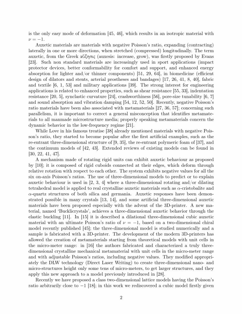
2 The auxetic latticeThe typical cell of the lattice is presented in Fig. 1a. It is composed of slender cross-shaped elements, represented in red and blue, joined by a hinge at the central point, asin Fig. 1b. Additional trusses, represented in green, connect the cross-shaped elementsat the end points. Introducing the terminology of crystal structure, the unit cell is acubic P (cP) Bravais or space lattice [34] with cubic symmetry. In Fig. 1b we indicatethe geometrical parameters characterizing the structure: p is the length of the arms ofthe cross-shaped elements and γ their inclination with respect to the truss elements. Thelongitudinal truss elements have cross section At, Young’s modulus Et and longitudinalstiffness kt = EtAt/(2p cos γ). The arms of the cross-shaped elements are considered asEuler beams with cross section Ac, second-moment of inertia Jc and Young’s modulus Ec.
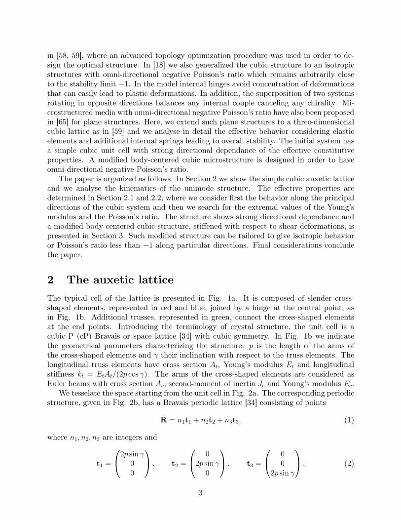
We tesselate the space starting from the unit cell in Fig. 2a. The corresponding periodicstructure, given in Fig. 2b, has a Bravais periodic lattice [34] consisting of points
R = n1t1 + n2t2 + n3t3, (1)
where n1, n2, n3 are integers and
t1 =
2p sin γ00
, t2 =
02p sin γ
0
, t3 =
00
2p sin γ
, (2)
3
x1
x2
x3
1
92
3
4
56
7
8
9
x2
x3
1 2
3
4
5 6
7
8
9
g
(a) (b)
Figure 1: (a) Three-dimensional cell of the cubic lattice. (b) Particular of a face of thetypical cell of the cubic lattice. The numbers identify the node in part (a) and (b).
x1
x2
x3
x1
x2
x3
(a) (b)
Figure 2: (a) Unit cell implemented in Comsol Multiphysics R©. (b) Three-dimensionalcubic lattice.
are the primitive vectors spanning the lattice.In the absence of trusses and for rigid cross-shaped elements we refer to [18] Section
3(a) and to [49] for the description of the kinematics of each couple of elements joinedat the central points. In particular, the only possible mode of deformation is homotheticexpansion or contraction. Following the systematic analysis for finite deformation given in
4
[43, 44, 45, 46] we show that the lattice is a unimode material. Let
T =[t1 t2 t3
]= 2p sin γ I (3)
be the ‘lattice matrix’, where I is the identity matrix. During the deformation the primitivevectors undergo an affine transformation and the matrix T describes a motion starting att = t0, with γ(t0) = γ0. At time t the deformation gradient is given by
F(t, t0) = [T(t)][T(t0)]−1. (4)
Then, the corresponding Cauchy-Green deformation tensor is the path
C(t, t0) = [T(t0)]−T [T(t)]T [T(t)][T(t0)]−1 =
(sin γ
sin γ0
)2
I. (5)
As for the planar square lattice in [18] the only possible path C(t, t0) lie on a one-dimensional curve and we can conclude that the lattice structure is unimode.
2.1 Effective propertiesThe lattice structure has cubic symmetry and its macroscopic behavior is described bythree independent elastic moduli. The elements of the lattice are sufficiently slender,so that classical structural theories can be conveniently applied to analyse the effectiveresponse. The structure has been studied numerically with the finite element code, ComsolMultiphysics R©. We have considered the following material and geometrical parameters:steel with Young’s modulus Ec = 200000 MPa, cross-shaped elements with length of thearms p = 10 mm and circular cross section having radius r = 0, 25 mm, so that the areais Ac = 0, 196 mm2. The truss elements have longitudinal stiffness kL and we introducethe non-dimensional stiffness ratio parameter α = kLp/(EcAc), between the longitudinalstiffness of the trusses and of the arms of the cross-shaped elements.
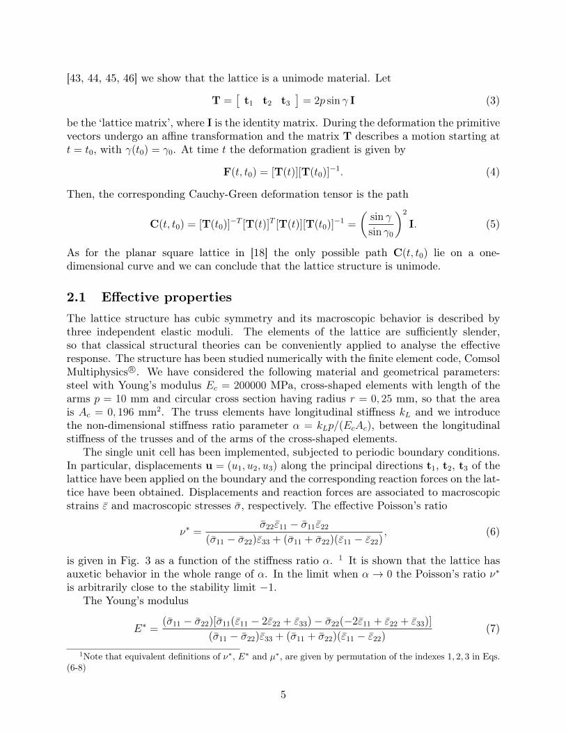
The single unit cell has been implemented, subjected to periodic boundary conditions.In particular, displacements u = (u1, u2, u3) along the principal directions t1, t2, t3 of thelattice have been applied on the boundary and the corresponding reaction forces on the lat-tice have been obtained. Displacements and reaction forces are associated to macroscopicstrains ε and macroscopic stresses σ, respectively. The effective Poisson’s ratio
ν∗ =σ22ε11 − σ11ε22
(σ11 − σ22)ε33 + (σ11 + σ22)(ε11 − ε22), (6)
is given in Fig. 3 as a function of the stiffness ratio α. 1 It is shown that the lattice hasauxetic behavior in the whole range of α. In the limit when α → 0 the Poisson’s ratio ν∗is arbitrarily close to the stability limit −1.
The Young’s modulus
E∗ =(σ11 − σ22)[σ11(ε11 − 2ε22 + ε33)− σ22(−2ε11 + ε22 + ε33)]
(σ11 − σ22)ε33 + (σ11 + σ22)(ε11 − ε22)(7)
1Note that equivalent definitions of ν∗, E∗ and µ∗, are given by permutation of the indexes 1, 2, 3 in Eqs.(6-8)
5
0.50.40.30.20.10
0
-0.1
-0.2
-0.3
-0.4
-0.5
-0.6
-0.7
-0.8
-0.9
-1.0
0.0250.020.0150.010.0050
-0.4
-0.5
-0.6
-0.7
-0.8
-0.9
-1.0
Figure 3: Poisson’s ratio ν∗ as a function of the non-dimensional stiffness ratio α =kLp/(EcAc).
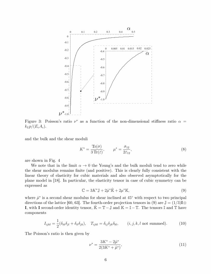
and the bulk and the shear moduli
K∗ =Tr(σ)
3Tr(ε), µ∗ =
σ12
2ε12
, (8)
are shown in Fig. 4We note that in the limit α → 0 the Young’s and the bulk moduli tend to zero while
the shear modulus remains finite (and positive). This is clearly fully consistent with thelinear theory of elasticity for cubic materials and also observed asymptotically for theplane model in [18]. In particular, the elasticity tensor in case of cubic symmetry can beexpressed as
C = 3K∗J + 2µ∗K + 2µ∗K, (9)
where µ∗ is a second shear modulus for shear inclined at 45◦ with respect to two principaldirections of the lattice [60, 63]. The fourth-order projection tensors in (9) are J = (1/3)I⊗I, with I second-order identity tensor, K = T− J and K = I−T. The tensors I and T havecomponents
Iijkl =1
2(δikδjl + δilδjk), Tijkl = δijδjkδkl, (i, j, k, l not summed). (10)
The Poisson’s ratio is then given by
ν∗ =3K∗ − 2µ∗
2(3K∗ + µ∗), (11)
6
0.50.40.30.20.10
300
400
500
600
700
200
100
0
0.50.40.30.20.1
0
0.025
0.05
0.075
0.10
0.125
0
(a) (b)
Figure 4: (a) Effective Young’s modulus E∗ and effective bulk modulus K∗. (b) Effectiveshear modulus µ∗. Elastic moduli are given as a function of the non-dimensional stiffnessratio α.
confirming that ν∗ → −1 when K∗ → 0 .From the results in Fig. 4b we also note that the shear modulus µ∗ is independent of the
ratio α, this is due to the fact that during shear deformation the longitudinal truss elementsare not deformed and the effective stiffness of the system is associated to longitudinaldeformations of the arms of the cross-shaped elements, a deformation mechanism alreadyobserved in the plane model [18].
2.2 Directional dependance of effective propertiesIn the previous Section the effective properties have been shown in the principal system ofthe lattice. Here we detail the directional dependance of the elastic moduli, in particularwe focus on the Poisson’s ratio and the Young’s modulus. It is convenient to consider thecompliance tensor S = C−1, which, for cubic material, in addition to the major and minorsymmetries Sijkl = Sklij and Sijkl = Sjikl = Sijlk, has
S1111 = S2222 = S3333, S1122 = S2233 = S3311, S1212 = S2323 = S3131, (12)
with the constrained of positive definiteness [61]
S1111 − S1122 > 0, S1111 + 2S1122 > 0, S1212 > 0. (13)
In a rotated frame of reference, where the rotation is described by the proper orthogonaltensor QT , the new components S ′ijkl of the compliance tensor are
S ′ijkl = QipQjqQkrQlsSpqrs. (14)
7
The elastic compliance S ′1111 and S ′1122 are:
S ′1111 = ninjnknlSijkl = S1111(n41 + n4
2 + n43) + (2S1122 + S1212)(n2
1n22 + n2
1n23 + n2
2n23), (15)
S ′1122 = ninjmkmlSijkl = S1111(n21m
21 + n2
2m22 + n2
3m23) + S1122(m2
1n22 +m2
2n21 +m2
1n23 +
m23n
21 + +m2
2n23 +m2
3n22) + S1212(n1n2m1m2 + n1n3m1m3 + n2n3m2m3), (16)
where n and m are orthogonal unit vectors.The dependance of the Young’s modulus on the direction, E∗ = E∗(n), can be obtained
from the relation1
E∗(n)= S ′1111, (17)
which, making use of Eq. (15) and the identity
n41 + n4
2 + n43 = 1− 2(n2
1n22 + n2
1n23 + n2
2n23), (18)
givesE∗(n) =
[S1111 − (2S1111 − 2S1122 − S1212)(n2
1n22 + n2
1n23 + n2
2n23)]−1
. (19)
The directional dependance of the Poisson’s ratio ν∗(n,m) is obtained from the relation
ν∗(n,m) = −S′1122
S ′1111
. (20)
We rewrite S ′1122 in Eq. (16) making use of the following identities:
1− (n21m
21 + n2
2m22 + n2
3m23) = (m2
1n22 +m2
2n21 +m2
1n23 +m2
3n21 +m2
2n23 +m2
3n22),
(n21m
21 + n2
2m22 + n2
3m23) = −2(n1n2m1m2 + n1n3m1m3 + n2n3m2m3), (21)
so that we have the simplified expression
S ′1122 = S1122 + (S1111 − S1122 − S1212/2)(n21m
21 + n2
2m22 + n2
3m23). (22)
Therefore, the directional dependance of the Poisson’s ratio ν∗(n,m) is
ν∗(n,m) = −S′1122
S ′1111
= −S1122 + (S1111 − S1122 − S1212/2)(n21m
21 + n2
2m22 + n2
3m23)
S1111 − 2(S1111 − S1122 − S1212/2)(n21n
22 + n2
2n23 + n2
3n21). (23)
2.2.1 Effective Young’s modulus
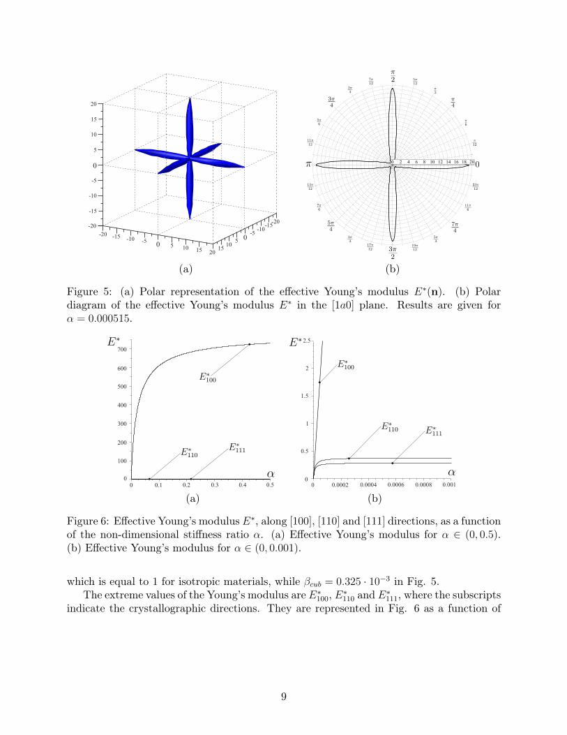
The Young’s modulus E∗ is shown in the polar plots in Fig. 5 as a function of the directionn. For low stiffness ratio α, which is equal to 0.000515 in Fig. 5, the structure has stronganisotropy highlighted by the strong variation of E∗, namely the ratio E∗max/E
∗min � 1.
Within the cubic behavior, the anisotropy can be quantified by the dimensionless Zeneranisotropy factor [19, 66]
βcub =2(S1111 − S1122)
4S1212
, (24)
8
0 5-5
-10-15
1015
20
-200
5
-5-10
-15
1015
-20
0
5
-5
-10
-15
10
15
20
-20
(a) (b)
Figure 5: (a) Polar representation of the effective Young’s modulus E∗(n). (b) Polardiagram of the effective Young’s modulus E∗ in the [1a0] plane. Results are given forα = 0.000515.
0.50.40.30.20.10
300
400
500
600
700
200
100
0
0.0010.00080.00060.00040.00020
0.5
1
1.5
2
2.5
0
(a) (b)
Figure 6: Effective Young’s modulus E∗, along [100], [110] and [111] directions, as a functionof the non-dimensional stiffness ratio α. (a) Effective Young’s modulus for α ∈ (0, 0.5).(b) Effective Young’s modulus for α ∈ (0, 0.001).
which is equal to 1 for isotropic materials, while βcub = 0.325 · 10−3 in Fig. 5.The extreme values of the Young’s modulus are E∗100, E∗110 and E∗111, where the subscripts
indicate the crystallographic directions. They are represented in Fig. 6 as a function of
9
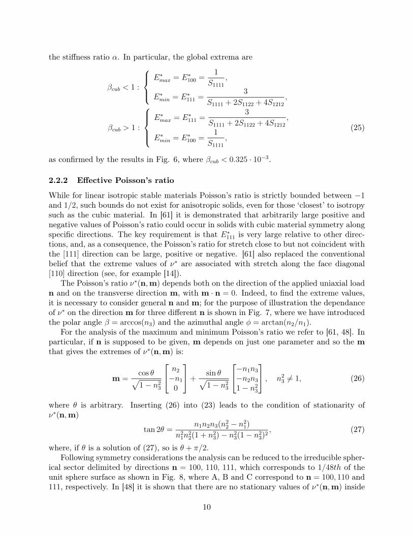
the stiffness ratio α. In particular, the global extrema are
βcub < 1 :
E∗max = E∗100 =
1
S1111
,
E∗min = E∗111 =3
S1111 + 2S1122 + 4S1212
,
βcub > 1 :
E∗max = E∗111 =
3
S1111 + 2S1122 + 4S1212
,
E∗min = E∗100 =1
S1111
,(25)
as confirmed by the results in Fig. 6, where βcub < 0.325 · 10−3.
2.2.2 Effective Poisson’s ratio
While for linear isotropic stable materials Poisson’s ratio is strictly bounded between −1and 1/2, such bounds do not exist for anisotropic solids, even for those ‘closest’ to isotropysuch as the cubic material. In [61] it is demonstrated that arbitrarily large positive andnegative values of Poisson’s ratio could occur in solids with cubic material symmetry alongspecific directions. The key requirement is that E∗111 is very large relative to other direc-tions, and, as a consequence, the Poisson’s ratio for stretch close to but not coincident withthe [111] direction can be large, positive or negative. [61] also replaced the conventionalbelief that the extreme values of ν∗ are associated with stretch along the face diagonal[110] direction (see, for example [14]).
The Poisson’s ratio ν∗(n,m) depends both on the direction of the applied uniaxial loadn and on the transverse direction m, with m · n = 0. Indeed, to find the extreme values,it is necessary to consider general n and m; for the purpose of illustration the dependanceof ν∗ on the direction m for three different n is shown in Fig. 7, where we have introducedthe polar angle β = arccos(n3) and the azimuthal angle φ = arctan(n2/n1).
For the analysis of the maximum and minimum Poisson’s ratio we refer to [61, 48]. Inparticular, if n is supposed to be given, m depends on just one parameter and so the mthat gives the extremes of ν∗(n,m) is:
m =cos θ√1− n2
3
n2
−n1
0
+sin θ√1− n2
3
−n1n3
−n2n3
1− n23
, n23 6= 1, (26)
where θ is arbitrary. Inserting (26) into (23) leads to the condition of stationarity ofν∗(n,m)
tan 2θ =n1n2n3(n2
2 − n21)
n21n
22(1 + n2
3)− n23(1− n2
3)2, (27)
where, if θ is a solution of (27), so is θ + π/2.Following symmetry considerations the analysis can be reduced to the irreducible spher-
ical sector delimited by directions n = 100, 110, 111, which corresponds to 1/48th of theunit sphere surface as shown in Fig. 8, where A, B and C correspond to n = 100, 110 and111, respectively. In [48] it is shown that there are no stationary values of ν∗(n,m) inside
10
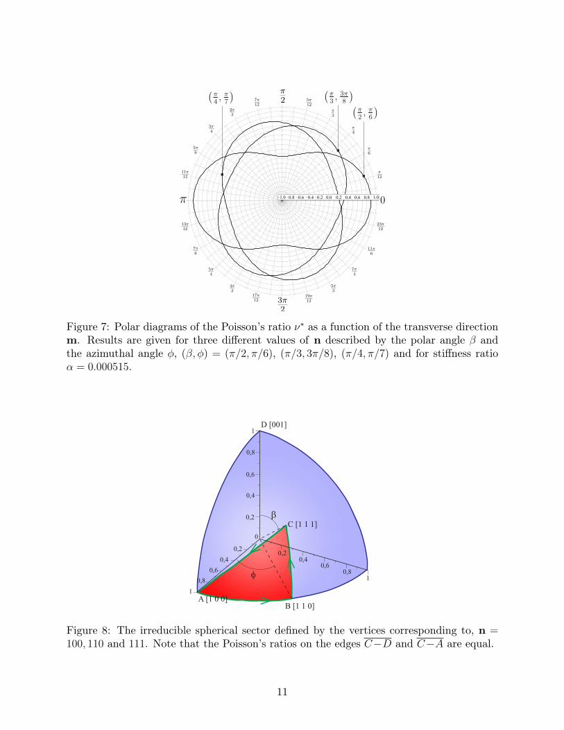
Figure 7: Polar diagrams of the Poisson’s ratio ν∗ as a function of the transverse directionm. Results are given for three different values of n described by the polar angle β andthe azimuthal angle φ, (β, φ) = (π/2, π/6), (π/3, 3π/8), (π/4, π/7) and for stiffness ratioα = 0.000515.
0
0,2
0,4
0,6
0,8
1
0,20,4
0,60,8
1
0,2
0,4
0,6
0,8
1
C [1 1 1]
B [1 1 0]A [1 0 0]
b
f
D [001]
Figure 8: The irreducible spherical sector defined by the vertices corresponding to, n =100, 110 and 111. Note that the Poisson’s ratios on the edges C−D and C−A are equal.
11
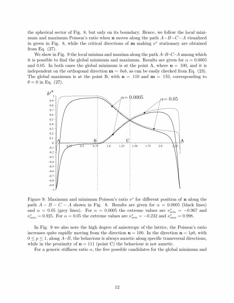
the spherical sector of Fig. 8, but only on its boundary. Hence, we follow the local mini-mum and maximum Poisson’s ratio when n moves along the path A−B−C−A visualizedin green in Fig. 8, while the critical directions of m making ν∗ stationary are obtainedfrom Eq. (27).
We show in Fig. 9 the local minima and maxima along the path A−B−C−A among whichit is possible to find the global minimum and maximum. Results are given for α = 0.0005and 0.05. In both cases the global minimum is at the point A, where n = 100, and it isindependent on the orthogonal direction m = 0ab, as can be easily checked from Eq. (23).The global maximum is at the point B, with n = 110 and m = 110, corresponding toθ = 0 in Eq. (27).
0.1
0.2
0.3
0.4
0.5
0.6
0.7
0.8
0.9
1
0BA
1.0-0.1
-0.2
-0.3
-0.4
-0.5
-0.6
-0.7
-0.8
-0.9
-1
1.25 1.50 1.75 2.0 2.250.750.50.25
C A
Figure 9: Maximum and minimum Poisson’s ratio ν∗ for different position of n along thepath A − B − C − A shown in Fig. 8. Results are given for α = 0.0005 (black lines)and α = 0.05 (grey lines). For α = 0.0005 the extreme values are ν∗min = −0.967 andν∗max = 0.925. For α = 0.05 the extreme values are ν∗min = −0.232 and ν∗max = 0.998.
In Fig. 9 we also note the high degree of anisotropy of the lattice, the Poisson’s ratioincreases quite rapidly moving from the direction n = 100. In the direction n = 1p0, with0 ≤ p ≤ 1, along A−B, the behaviour is always auxetic along specific transversal directions,while in the proximity of n = 111 (point C) the behaviour is not auxetic.
For a generic stiffness ratio α, the five possible candidates for the global minimum and
12
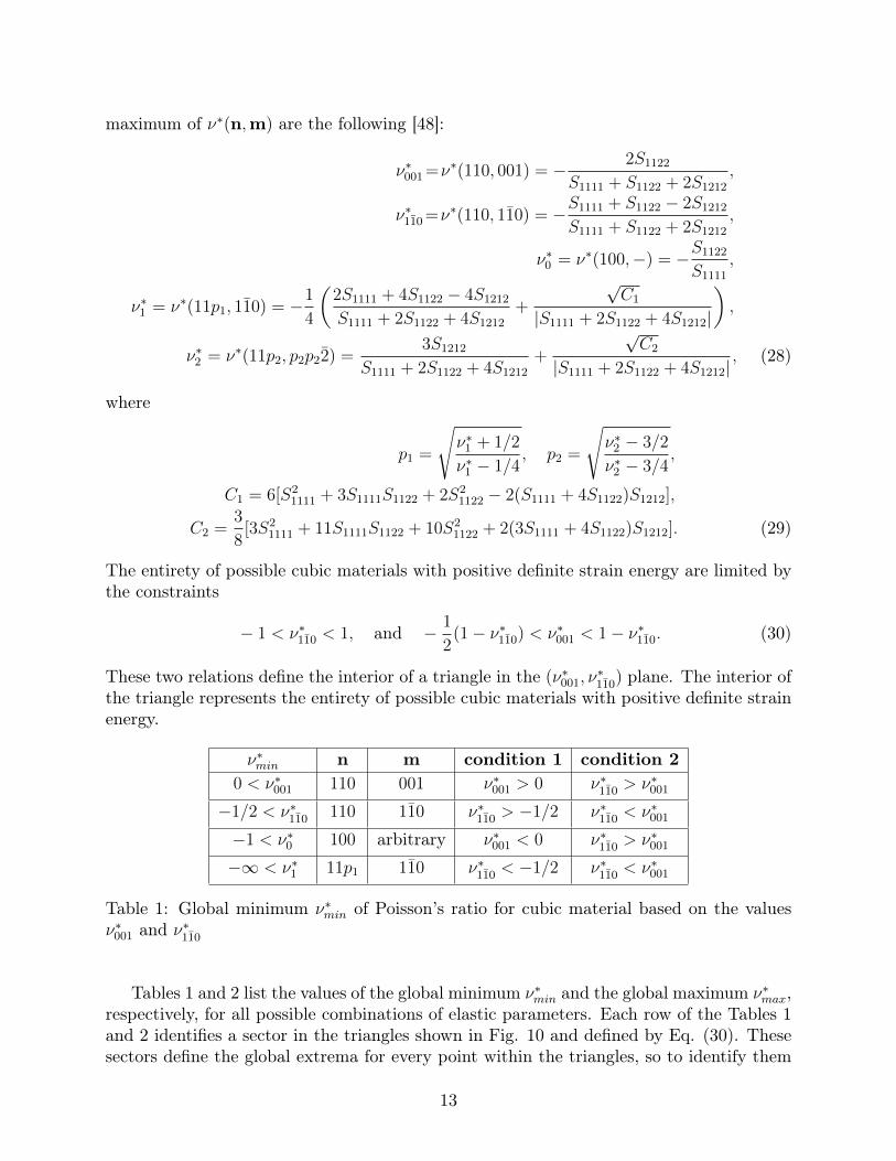
maximum of ν∗(n,m) are the following [48]:
ν∗001 =ν∗(110, 001) = − 2S1122
S1111 + S1122 + 2S1212
,
ν∗110 =ν∗(110, 110) = −S1111 + S1122 − 2S1212
S1111 + S1122 + 2S1212
,
ν∗0 = ν∗(100,−) = −S1122
S1111
,
ν∗1 = ν∗(11p1, 110) = −1
4
(2S1111 + 4S1122 − 4S1212
S1111 + 2S1122 + 4S1212
+
√C1
|S1111 + 2S1122 + 4S1212|
),
ν∗2 = ν∗(11p2, p2p22) =3S1212
S1111 + 2S1122 + 4S1212
+
√C2
|S1111 + 2S1122 + 4S1212|, (28)
where
p1 =
√ν∗1 + 1/2
ν∗1 − 1/4, p2 =
√ν∗2 − 3/2
ν∗2 − 3/4,
C1 = 6[S21111 + 3S1111S1122 + 2S2
1122 − 2(S1111 + 4S1122)S1212],
C2 =3
8[3S2
1111 + 11S1111S1122 + 10S21122 + 2(3S1111 + 4S1122)S1212]. (29)
The entirety of possible cubic materials with positive definite strain energy are limited bythe constraints
− 1 < ν∗110 < 1, and − 1
2(1− ν∗110) < ν∗001 < 1− ν∗110. (30)
These two relations define the interior of a triangle in the (ν∗001, ν∗110) plane. The interior of
the triangle represents the entirety of possible cubic materials with positive definite strainenergy.
ν∗min n m condition 1 condition 20 < ν∗001 110 001 ν∗001 > 0 ν∗110 > ν∗001
−1/2 < ν∗110 110 110 ν∗110 > −1/2 ν∗110 < ν∗001
−1 < ν∗0 100 arbitrary ν∗001 < 0 ν∗110 > ν∗001
−∞ < ν∗1 11p1 110 ν∗110 < −1/2 ν∗110 < ν∗001
Table 1: Global minimum ν∗min of Poisson’s ratio for cubic material based on the valuesν∗001 and ν∗110
Tables 1 and 2 list the values of the global minimum ν∗min and the global maximum ν∗max,respectively, for all possible combinations of elastic parameters. Each row of the Tables 1and 2 identifies a sector in the triangles shown in Fig. 10 and defined by Eq. (30). Thesesectors define the global extrema for every point within the triangles, so to identify them
13
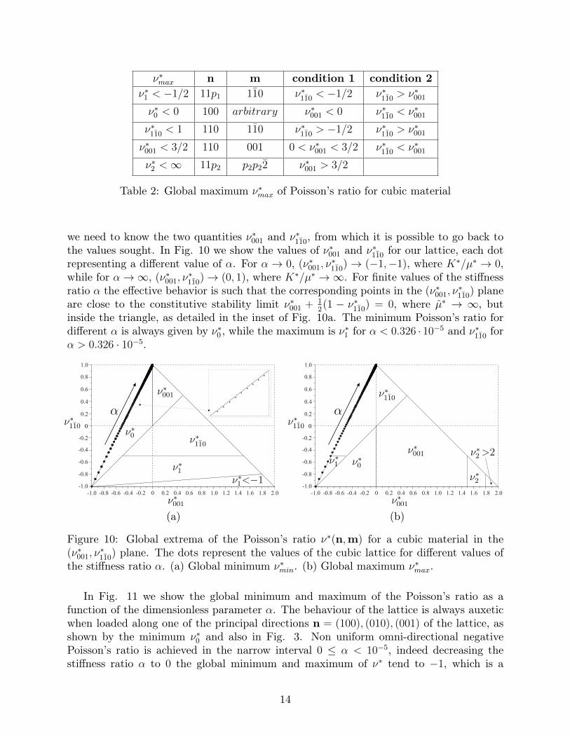
ν∗max n m condition 1 condition 2ν∗1 < −1/2 11p1 110 ν∗110 < −1/2 ν∗110 > ν∗001
ν∗0 < 0 100 arbitrary ν∗001 < 0 ν∗110 < ν∗001
ν∗110 < 1 110 110 ν∗110 > −1/2 ν∗110 > ν∗001
ν∗001 < 3/2 110 001 0 < ν∗001 < 3/2 ν∗110 < ν∗001
ν∗2 <∞ 11p2 p2p22 ν∗001 > 3/2
Table 2: Global maximum ν∗max of Poisson’s ratio for cubic material
we need to know the two quantities ν∗001 and ν∗110, from which it is possible to go back tothe values sought. In Fig. 10 we show the values of ν∗001 and ν∗110 for our lattice, each dotrepresenting a different value of α. For α → 0, (ν∗001, ν
∗110)→ (−1,−1), where K∗/µ∗ → 0,
while for α→∞, (ν∗001, ν∗110)→ (0, 1), where K∗/µ∗ →∞. For finite values of the stiffness
ratio α the effective behavior is such that the corresponding points in the (ν∗001, ν∗110) plane
are close to the constitutive stability limit ν∗001 + 12(1 − ν∗110) = 0, where µ∗ → ∞, but
inside the triangle, as detailed in the inset of Fig. 10a. The minimum Poisson’s ratio fordifferent α is always given by ν∗0 , while the maximum is ν∗1 for α < 0.326 · 10−5 and ν∗110 forα > 0.326 · 10−5.
0 0.2 0.4 0.6 0.8 1.21.0 1.4 1.6 1.8 2.0-1.0 -0.8 -0.6 -0.4 -0.2
-0.2
-0.4
-0.6
-0.8
-1.0
0.2
0.4
0.6
0.8
1.0
0 0.2 0.4 0.6 0.8 1.21.0 1.4 1.6 1.8 2.0-1.0 -0.8 -0.6 -0.4 -0.2
-0.2
-0.4
-0.6
-0.8
-1.0
0.2
0.4
0.6
0.8
1.0
(a) (b)
Figure 10: Global extrema of the Poisson’s ratio ν∗(n,m) for a cubic material in the(ν∗001, ν
∗110) plane. The dots represent the values of the cubic lattice for different values of
the stiffness ratio α. (a) Global minimum ν∗min. (b) Global maximum ν∗max.
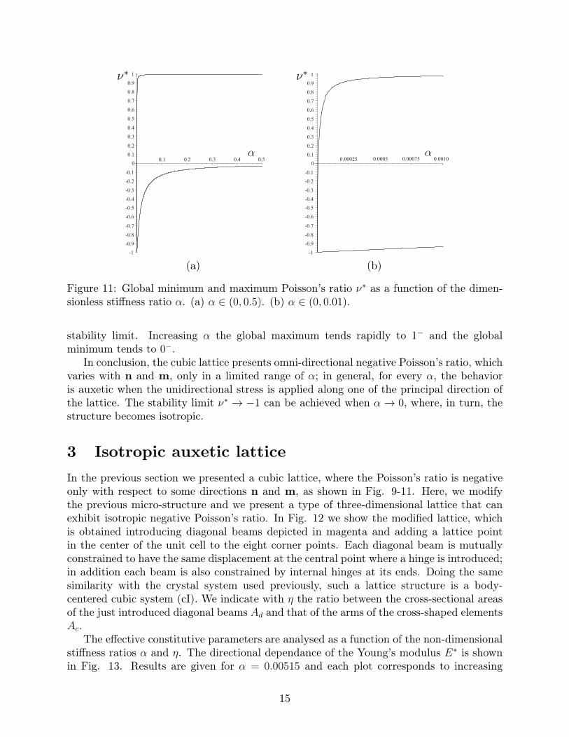
In Fig. 11 we show the global minimum and maximum of the Poisson’s ratio as afunction of the dimensionless parameter α. The behaviour of the lattice is always auxeticwhen loaded along one of the principal directions n = (100), (010), (001) of the lattice, asshown by the minimum ν∗0 and also in Fig. 3. Non uniform omni-directional negativePoisson’s ratio is achieved in the narrow interval 0 ≤ α < 10−5, indeed decreasing thestiffness ratio α to 0 the global minimum and maximum of ν∗ tend to −1, which is a
14
0.50.40.30.20.1
0.1
0.2
0.3
0.4
0.5
0.6
0.7
0.8
0.9
1
0
-0.1
-0.2
-0.3
-0.4
-0.5
-0.6
-0.7
-0.8
-0.9
-1
0.1
0.2
0.3
0.4
0.5
0.6
0.7
0.8
0.9
1
0
-0.1
0.00100.000750.00050.00025
-0.2
-0.3
-0.4
-0.5
-0.6
-0.7
-0.8
-0.9
-1
(a) (b)
Figure 11: Global minimum and maximum Poisson’s ratio ν∗ as a function of the dimen-sionless stiffness ratio α. (a) α ∈ (0, 0.5). (b) α ∈ (0, 0.01).
stability limit. Increasing α the global maximum tends rapidly to 1− and the globalminimum tends to 0−.
In conclusion, the cubic lattice presents omni-directional negative Poisson’s ratio, whichvaries with n and m, only in a limited range of α; in general, for every α, the behavioris auxetic when the unidirectional stress is applied along one of the principal direction ofthe lattice. The stability limit ν∗ → −1 can be achieved when α→ 0, where, in turn, thestructure becomes isotropic.
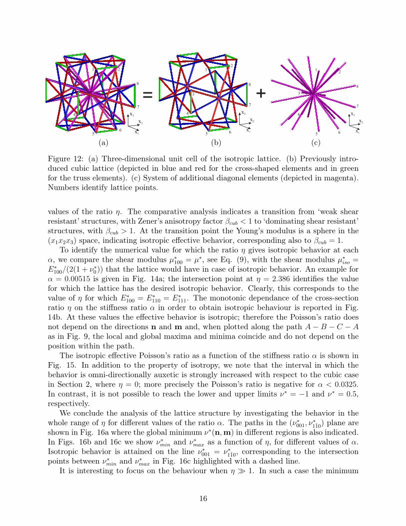
3 Isotropic auxetic latticeIn the previous section we presented a cubic lattice, where the Poisson’s ratio is negativeonly with respect to some directions n and m, as shown in Fig. 9-11. Here, we modifythe previous micro-structure and we present a type of three-dimensional lattice that canexhibit isotropic negative Poisson’s ratio. In Fig. 12 we show the modified lattice, whichis obtained introducing diagonal beams depicted in magenta and adding a lattice pointin the center of the unit cell to the eight corner points. Each diagonal beam is mutuallyconstrained to have the same displacement at the central point where a hinge is introduced;in addition each beam is also constrained by internal hinges at its ends. Doing the samesimilarity with the crystal system used previously, such a lattice structure is a body-centered cubic system (cI). We indicate with η the ratio between the cross-sectional areasof the just introduced diagonal beams Ad and that of the arms of the cross-shaped elementsAc.
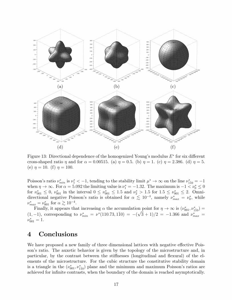
The effective constitutive parameters are analysed as a function of the non-dimensionalstiffness ratios α and η. The directional dependance of the Young’s modulus E∗ is shownin Fig. 13. Results are given for α = 0.00515 and each plot corresponds to increasing
15
=
x1
x2
x3
1 2
3
4
56
9
8
7
x1
x2
x3
1
2
3
4
56
7
8
+
x1
x2
x3
12
3
4
56
7
8
(a) (b) (c)
Figure 12: (a) Three-dimensional unit cell of the isotropic lattice. (b) Previously intro-duced cubic lattice (depicted in blue and red for the cross-shaped elements and in greenfor the truss elements). (c) System of additional diagonal elements (depicted in magenta).Numbers identify lattice points.
values of the ratio η. The comparative analysis indicates a transition from ‘weak shearresistant’ structures, with Zener’s anisotropy factor βcub < 1 to ‘dominating shear resistant’structures, with βcub > 1. At the transition point the Young’s modulus is a sphere in the(x1x2x3) space, indicating isotropic effective behavior, corresponding also to βcub = 1.
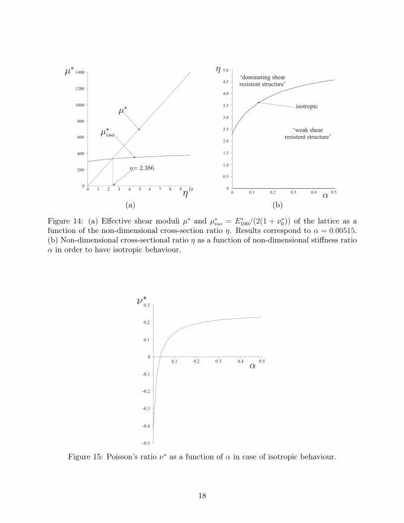
To identify the numerical value for which the ratio η gives isotropic behavior at eachα, we compare the shear modulus µ∗100 = µ∗, see Eq. (9), with the shear modulus µ∗iso =E∗100/(2(1 + ν∗0)) that the lattice would have in case of isotropic behavior. An example forα = 0.00515 is given in Fig. 14a; the intersection point at η = 2.386 identifies the valuefor which the lattice has the desired isotropic behavior. Clearly, this corresponds to thevalue of η for which E∗100 = E∗110 = E∗111. The monotonic dependance of the cross-sectionratio η on the stiffness ratio α in order to obtain isotropic behaviour is reported in Fig.14b. At these values the effective behavior is isotropic; therefore the Poisson’s ratio doesnot depend on the directions n and m and, when plotted along the path A − B − C − Aas in Fig. 9, the local and global maxima and minima coincide and do not depend on theposition within the path.
The isotropic effective Poisson’s ratio as a function of the stiffness ratio α is shown inFig. 15. In addition to the property of isotropy, we note that the interval in which thebehavior is omni-directionally auxetic is strongly increased with respect to the cubic casein Section 2, where η = 0; more precisely the Poisson’s ratio is negative for α < 0.0325.In contrast, it is not possible to reach the lower and upper limits ν∗ = −1 and ν∗ = 0.5,respectively.
We conclude the analysis of the lattice structure by investigating the behavior in thewhole range of η for different values of the ratio α. The paths in the (ν∗001, ν
∗110) plane are
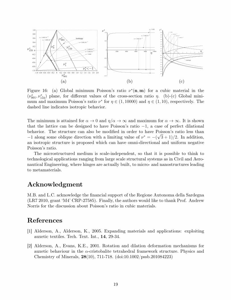
shown in Fig. 16a where the global minimum ν∗(n,m) in different regions is also indicated.In Figs. 16b and 16c we show ν∗min and ν∗max as a function of η, for different values of α.Isotropic behavior is attained on the line ν∗001 = ν∗110, corresponding to the intersectionpoints between ν∗min and ν∗max in Fig. 16c highlighted with a dashed line.
It is interesting to focus on the behaviour when η � 1. In such a case the minimum
16
-300
-200
-100
0
300
200
-300
-200
-100
0
200
100
-200
-100
0
300
200
100
300
100
-300
-200
-100
0
400
300
200
-300
-200
-100
0
400
200
100
-200
-300
-100
0
300
200
100
400
-400
300
100
-400
-300
-500-400
-200-100
0
500400
300200
100
-300
-500-400
-200-100
0
500400
300200
100
-300
-500
-400
-200
-100
0
500
400
300
200
100
(a) (b) (c)
-600
-400
-200
0
600
400
200
-600
-400
-200
0
600
400
200
-400
-600
-200
0
600
400
200
-1000
-600
-2000
1000
800
-1000
-800
-400
0
400200
-400
-200
0
1000
400
200
600 600
800
600
-600
-800
-600
-200
800
1000
400200
-400
-800-2000
-1200
-4000
2000
1600
-2000-1600
-800
0
800400
-800
-400
0
2000
800
400
1200 1200
1600
1200
-1200
-1600
-1200
-400
16002000
800400
-800
-1600
(d) (e) (f)
Figure 13: Directional dependence of the homogenized Young’s modulus E∗ for six differentcross-shaped ratio η and for α = 0.00515. (a) η = 0.5. (b) η = 1. (c) η = 2.386. (d) η = 5.(e) η = 10. (f) η = 100.
Poisson’s ratio ν∗min is ν∗1 < −1, tending to the stability limit µ∗ →∞ on the line ν∗110 = −1when η →∞. For α = 5.092 the limiting value is ν∗1 = −1.32. The maximum is−1 < ν∗0 ≤ 0for ν∗001 ≤ 0, ν∗001 in the interval 0 ≤ ν∗001 ≤ 1.5 and ν∗2 > 1.5 for 1.5 ≤ ν∗001 ≤ 2. Omni-directional negative Poisson’s ratio is obtained for α . 10−4, namely ν∗max = ν∗0 , whileν∗max = ν∗001 for α & 10−4.
Finally, it appears that increasing α the accumulation point for η →∞ is (ν∗001, ν∗110) =
(1,−1), corresponding to ν∗min = ν∗(110.73, 110) = −(√
3 + 1)/2 = −1.366 and ν∗max =ν∗001 = 1.
4 ConclusionsWe have proposed a new family of three dimensional lattices with negative effective Pois-son’s ratio. The auxetic behavior is given by the topology of the microstructure and, inparticular, by the contrast between the stiffnesses (longitudinal and flexural) of the el-ements of the microstructure. For the cubic structure the constitutive stability domainis a triangle in the (ν∗001, ν
∗110) plane and the minimum and maximum Poisson’s ratios are
achieved for infinite contrasts, when the boundary of the domain is reached asymptotically.
17
0 1 2 3 4 5 6 7 8 9 100
200
400
600
800
1000
1200
1400
0.50.40.30.20.1
0.5
1.5
2.0
2.5
3.0
3.5
4.0
4.5
5.0
00
1.0
‘dominating shearresistent structure’
‘weak shearresistent structure’
isotropic
(a) (b)
Figure 14: (a) Effective shear moduli µ∗ and µ∗iso = E∗100/(2(1 + ν∗0)) of the lattice as afunction of the non-dimensional cross-section ratio η. Results correspond to α = 0.00515.(b) Non-dimensional cross-sectional ratio η as a function of non-dimensional stiffness ratioα in order to have isotropic behaviour.
0.3
0.2
0
-0.1
-0.2
-0.3
-0.4
-0.5
0.1
0.50.40.30.20.1
Figure 15: Poisson’s ratio ν∗ as a function of α in case of isotropic behaviour.
18
0 0.2 0.4 0.6 0.8 1.21.0 1.4 1.6 1.8 2.0-1.0 -0.8 -0.6 -0.4 -0.2
-0.2
-0.4
-0.6
-0.8
-1.0
0.2
0.4
0.6
0.8
1.0
isotropy
0
1.0
0.5
-0.5
-1.0
-1.5
1000080006000400020000.1
0.2
0.3
0.4
0.5
0.6
0.7
0.8
0.9
1
0
-0.1
-0.2
-0.3
-0.4
-0.5
-0.6
-0.7
-0.8
-0.9
-1
105 6 87 94321
isotropy
(a) (b) (c)
Figure 16: (a) Global minimum Poisson’s ratio ν∗(n,m) for a cubic material in the(ν∗001, ν
∗110) plane, for different values of the cross-section ratio η. (b)-(c) Global mini-
mum and maximum Poisson’s ratio ν∗ for η ∈ (1, 10000) and η ∈ (1, 10), respectively. Thedashed line indicates isotropic behavior.
The minimum is attained for α→ 0 and η/α→∞ and maximum for α→∞. It is shownthat the lattice can be designed to have Poisson’s ratio −1, a case of perfect dilationalbehavior. The structure can also be modified in order to have Poisson’s ratio less than−1 along some oblique direction with a limiting value of ν∗ = −(
√3 + 1)/2. In addition,
an isotropic structure is proposed which can have omni-directional and uniform negativePoisson’s ratio.
The microstructured medium is scale-independent, so that it is possible to think totechnological applications ranging from large scale structural systems as in Civil and Aero-nautical Engineering, where hinges are actually built, to micro- and nanostructures leadingto metamaterials.
AcknowledgmentM.B. and L.C. acknowledge the financial support of the Regione Autonoma della Sardegna(LR7 2010, grant ‘M4’ CRP-27585). Finally, the authors would like to thank Prof. AndrewNorris for the discussion about Poisson’s ratio in cubic materials.
References[1] Alderson, A., Alderson, K., 2005. Expanding materials and applications: exploiting
auxetic textiles. Tech. Text. Int., 14, 29-34.
[2] Alderson, A., Evans, K.E., 2001. Rotation and dilation deformation mechanisms forauxetic behaviour in the α-cristobalite tetrahedral framework structure. Physics andChemistry of Minerals, 28(10), 711-718. (doi:10.1002/pssb.201084223)
19
[3] Alderson, A., Evans, K.E., 2002. Molecular origin of auxetic behav-ior in tetrahedral framework silicates. Phys. Rev. Lett., 89, 225503.(doi:10.1103/PhysRevLett.89.225503)
[4] Alderson, A., Evans, K.E., 2009. Deformation mechanisms leading to auxetic behaviourin the α-cristobalite and α-quartz structures of both silica and germania. Journal ofphysics: condensed matter, 21(025401). (doi:10.1088/0953-8984/21/2/025401)
[5] Alderson, K.L., Fitzgerald, A., Evans, K.E., 2000 The strain dependent indenta-tion resilience of auxetic microporous polyethylene. J. Mater. Sci., 35, 4039-4047.(doi:10.1023/A:1004830103411)
[6] Alderson, A., Rasburn, J., Ameer-Beg, S., Mullarkey, P.G., Perrie, W., Evans, K.E.,2000. An Auxetic Filter:? A Tuneable Filter Displaying Enhanced Size Selectivity orDefouling Properties. Ind. Eng. Chem. Res., 39(3), 654-665. (doi:10.1021/ie990572w)
[7] Alderson, A., Rasburn, J., Evans K.E., Grima, J.N., 2001. Auxetic polymeric filtersdisplay enhanced de-fouling and pressure compensation properties. Membr. Technol.,137, 6-8. (doi:10.1016/S0958-2118(01)80299-8)
[8] Ali, M.N., Busfield, J.J.C., Rehman, I.U., 2014. Auxetic oesophageal stents: struc-ture and mechanical properties. J. Mater. Sci. - Mater. Med. 25(2), 527-553.(doi:10.1007/s10856-013-5067-2)
[9] Almgren, R.F., 1985. An isotropic three-dimensional structure with Poisson’s ratio= −1. J. Elasticity, 15(4), 427-430. (doi:10.1007/BF00042531)
[10] Attard, D., Grima, J.N., 2012. A three-dimensional rotating rigid units networkexhibiting negative Poisson’s ratios. Phys. Status Solidi B, 249(7), 1330-1338.(doi:10.1002/pssb.201084223)
[11] Babaee, S., Shim, J., Weaver, J.C., Patel, N., Bertoldi, K., 2013. 3D SoftMetamaterials with Negative Poisson’s Ratio. New J. Phys., 25(36), 5044-5049.(doi:10.1002/adma.201301986)
[12] Baravellia, E., Ruzzene, M., 2013. Internally resonating lattices for bandgap gen-eration and low-frequency vibration control. J. Sound Vib., 332(25), 6562-6579.(doi:10.1016/j.jsv.2013.08.014)
[13] Baughman, R.H., Galvao, D.S., 1993. Negative Poisson’s ratio as a common featureof cubic metals. Nature, 365, 735-737. (doi:10.1038/365735a0)
[14] Baughman, R.H., Shacklette, J.M., Zakhidev, A.A., Stafstrom, S., 1998. Nega-tive Poisson’s ratio as a common feature of cubic metals. Nature, 392, 362-365.(doi:10.1038/32842)
[15] Buckmann, T., Schittny, R., Thiel, M., Kadic, M., Milton, G.W., Wegener, M., 2014.On three-dimensional dilational elastic metamaterials. New J. Phys., 16, 033032.(doi:10.1088/1367-2630/16/3/033032)
20
[16] Buckmann, T., Stenger, N., Kadic, M., Kaschke, J., Frolich, A., Kennerknecht,T., Eberl, C., Thiel, M., Wegener, M., 2012. Tailored 3D Mechanical Metamateri-als Made by Dip-in Direct-Laser-Writing Optical Lithography. Advanced Materials,24(20), 2710-2714. (doi:0.1002/adma.201200584)
[17] Caddock, B.D., Evans, K E., 1989. Microporous Materials with Negative Poisson’sRatios, I. Microstructure and Mechanical Properties. J. Phys. D: Appl. Phys., 22,1877. (doi:10.1088/0022-3727/22/12/012)
[18] Cabras, L. and Brun, M., 2014. Auxetic two-dimensional lattices with Pois-son’s ratio arbitrarily close to -1. Proc. R. Soc. Lond. A, 470, 20140538. (doi:10.1098/rspa.2014.0538)
[19] Cazzani, A., Rovati, M., 2003. Extrema of Young’s modulus for cubic and trans-versely isotropic solids. Int. J. Solids Struct., 40(7), 1713-1744. (doi:10.1016/S0020-7683(02)00668-6)
[20] Coenen, V.L., Alderson, K.L., 2011. Mechanisms of failure in the static indenta-tion resistance of auxetic carbon fibre laminates. Phys. Status Solidi B, 248, 66-72.(doi:10.1002/pssb.201083977)
[21] Craster, R.V., Guenneau, S., 2013. Acoustic Metamaterials: Negative Refraction,Imaging, Lensing and Cloaking (Springer Series in Materials Science). Soringer, UK.
[22] Elipe, J.C.A., Lantada, A.D., 2012. Comparative study of auxetic geometries bymeans of computer-aided design and engineering Smart Mater. Struct., 21, 105004.(doi:10.1088/0964-1726/21/10/105004)
[23] Evans, K.E., 1991. Auxetic polymers: a new range of materials. Endeavour, 15(4),170-174. (doi:10.1016/0160-9327(91)90123-S)
[24] Evans, K.E., Alderson, A., 2000. Auxetic materials: functional materials and struc-tures from lateral thinking! Adv. Mater., 12, 617-628. (doi:10.1002/(SICI)1521-4095(200005)12:9<617::AID-ADMA617>3.0.CO;2-3)
[25] Friis, E.A., Lakes, R.S., Park, J.B., 1988. Negative Poisson’s ratio polymeric andmetallic foams. J. Mater. Sci., 23, 4406-4414. (doi:10.1007/BF00551939)
[26] Gatt, R., Caruana-Gauci, R., Attard, D., Casha, A.R., Wolak, W., Dudek,K., Mizzi, L., Grima, J.N., 2014. On the properties of real finite-sized planarand tubular stent-like auxetic structures. Phys. Status Solidi B, 251(2), 321-327.(doi:10.1002/pssb.201384257)
[27] Gatt, R., Mizzi, L., Azzopardi, J.I., Azzopardi, K.M., Attard, D., Casha, A., Briffa,J., Grima, J.N., 2014. Hierarchical Auxetic Mechanical Metamaterials. Sci. Rep., 5,8395. (doi:10.1038/srep08395)
[28] Gibson, L.J., Ashby, M.F., 1997. Cellular Solids: Structure and Properties (2nd ed.).Cambridge University Press.
21
[29] Glazzard, M., Breedon, P., 2014. Weft-knitted auxetic textile design. Phys. StatusSolidi B, 251(2), 267-272. (doi:10.1002/pssb.201384240)
[30] Greaves, G.N., Greer, A.L., Lakes, R.S., Rouxel, T., 2011. Poisson’s ratio and modernmaterials. Nat. Mater., 10, 823-827. (doi:10.1038/nmat3134)
[31] Guo, C.Y., Wheeler, L., 2006. Extreme Poisson’s ratios and related elastic crystalproperties. J. Mech. Phys. Solids, 54(4), 690-707. (doi:10.1016/j.jmps.2005.11.002)
[32] Hall, L.J., Coluci, V.R., Galvao, D.S., Kozlov, M.E., Zhang, M., Dantas, S.O., Baugh-man, R.H., 2008. Sign change of Poisson’s ratio for carbon nanotube sheets. Science,320, 504-507. (doi:10.1126/science.1149815)
[33] Ju, J., Summers, J.D., 2011. Hyperelastic constitutive modeling of hexagonal hon-eycombs subjected to in-plane shear loading. J. Eng. Mater. Technol., 133, 011005.(doi:10.1115/1.4002640)
[34] Kittel, C., 1996. Introduction to Solid State Physics (7th ed.). New York: John Wiley& Sons.
[35] Kolpakov, A.G., 1985. Determination of the average characteristics of elastic frame-works. J. Appl. Math. Mech., 49(6), 0969-977. (doi:10.1016/0021-8928(85)90011-5)
[36] Krodel, S., Delpero, T., Bergamini, A., Ermanni, P., Kochmann, D.M.,2014. 3D Auxetic Microlattices with Independently Controllable Acoustic BandGaps and Quasi-Static Elastic Moduli. Adv. Eng. Mater., 16(4), 357-363.(odi:10.1002/adem.201300264)
[37] Lakes, R.S., 1987. Foam structures with a negative Poisson’s ratio. Science, 235, 1038-1040. (doi:10.1126/science.235.4792.1038)
[38] Love, A.E.H., 1944. A treatise on the mathematical theory of elasticity, 4th edn. NewYork, NY, Dover Publications.
[39] Ma, Z.D., Liu, Y.Y., Liu, X.M., Sun, C., Cui, Y., 2011. Ultralightweight runflat tiresbased upon negative Poisson ratio (NPR) auxetic structures. Patent 2011/0168313A1,USA.
[40] Martz, E.O., Lakes, R.S., Goel, V.K., Park, J.B., 2005. Design of an artificial inter-vertebral disc exhibiting a negative Poisson’s ratio. Cell. Polym., 24, 127-138.
[41] Mir, M., Ali, M.N., Sami, J., Ansari, U., 2014. Review of Mechanics and Applicationsof Auxetic Structures. Adv. Mater. Sci. Eng., 753496. (doi:10.1155/2014/753496)
[42] Milton, G.W., 1992. Composite materials with Poisson’s ratios close to -1. J. Mech.Phys. Solids, 40(5), 1105-1137. (doi:10.1016/0022-5096(92)90063-8)
[43] Milton, G.W., Cherkaev, A.V., 1995. Which elasticity tensors are realizable? J. Eng.Mat. Tech., 117, 483-493. (doi:10.1115/1.2804743)
22
[44] Milton, G.W., 2002. The Theory of Composites. Cambridge University Press.
[45] Milton, G.W., 2013. Complete characterization of the macroscopic deformations ofperiodic unimode metamaterials of rigid bars and pivots. J. Mech. Phys. Solids, 61(7),1543-1560. (doi:10.1016/j.jmps.2012.08.011)
[46] Milton, G.W., 2013. Adaptable nonlinear bimode metamaterials using rigidbars, pivots, and actuators. J. Mech. Phys. Solids, 61(7), 1561-1568.(doi:10.1016/j.jmps.2012.08.012)
[47] Milton, G.W., 2015. New examples of three-dimensional dilational materials. Phys.Status Solidi B, 1-5. (doi:10.1002/pssb.201552297)
[48] Norris, A.N., 2006. Poisson’s ratio in cubic materials. Proc. R. Soc. Lond. A,462(275), 3385-3405. (doi:10.1098/rspa.2006.1726)
[49] Patel, J., Ananthasuresh, GK., 2007. A kinematic theory for radially foldable planarlinkages. Int. J. Solids Struct., 44, 6279-6298. (doi:10.1016/j.ijsolstr.2007.02.023)
[50] Ruzzene, M., Scarpa, F., 2003. Control of Wave Propagation in SandwichBeams with Auxetic Core. J. Intell. Mater. Syst. Struct., 14(7), 443-453.(doi:10.1177/1045389X03035515)
[51] Sanamia, M., Raviralaa, N., Alderson, K., Alderson, A., 2014. Aux-etic materials for sports applications. Procedia Engineering 72, 453-458.(doi:10.1016/j.proeng.2014.06.079)
[52] Scarpa, F., Ciffo, L.G., Yates, J.R., 2004. Dynamic properties of high structural in-tegrity auxetic open cell foam. Smart Mater. Struct., 13, 49-56. (doi:10.1088/0964-1726/13/1/006)
[53] Scarpa, F., Giacomin, J., Zhang Y, Pastorino, P., 2005. Mechanical performance ofauxetic polyurethane foam for antivibration glove applications. Cell. Polym., 24(5),253-268.
[54] Scarpa, F., Smith, F.C., 2004. Passive and MR fluid-coated auxetic PU foam me-chanical, acoustic, and electromagnetic properties. J. Intell. Mater. Syst. Struct., 15,973-979. (doi:10.1177/1045389X04046610)
[55] Scarpa, F., Tomlin, P.J., 2000. On the transverse shear modulus of negative Poisson’sratio honeycomb structures. Fatigue Fract. Eng. M., 23, 717-720. (doi:10.1046/j.1460-2695.2000.00278.x)
[56] Scarpa, F., Yates, J.R., Ciffo, L.G., Patsias, S., 2002. Dynamic crushing of auxeticopen-cell polyurethane foam. Proc. Instn. Mech. Engrs. C - J. Mech. Eng. Sci., 216,1153-1156.
[57] Shin, D., Urzhumov, Y., Lim, D., Kim, K., Smith, D.R., 2014. A versatile smarttransformation optics device with auxetic elasto-electromagnetic metamaterials. Sci.Rep., 4, 4084. (doi:10.1038/srep04084)
23
[58] Sigmund, O., 1994. Materials with prescribed constitutive parameters: An inversehomogenization problem. Int. J. Solids Struct., 31(17), 2313-2329. (doi:10.1016/0020-7683(94)90154-6)
[59] Sigmund, O., 1995. Tailoring materials with prescribed elastic properties. Mech.Mater., 20, 351-368. (doi:10.1016/0167-6636(94)00069-7)
[60] Thomas, T.Y., (Lord Kelvin), 1965. On the stress-strain relations for cubic crystals.Proc. Natl. Acad. Sci. USA, 55, 235-239.
[61] Ting, T.C.T., Chen, T., 2005. Poisson’s ratio for anisotropic elastic materials can haveno bounds. Quart. J. Mech. Appl. Math., 58(1), 73-82. (doi: 10.1093/qjmamj/hbh021)
[62] Yeganeh-Haeri, A., Weidner, D.J., Parise, J.B., 1992. Elasticity of α-cristobalite:a silicon dioxide with a negative Poisson’s ratio. Science, 257, 650-652.(doi:10.1126/science.257.5070.650)
[63] Walpole, L.J., 1984. Fourth-rank tensors of the thirty two crystal classes: multiplica-tion tables. Proc. R. Soc. Lond. A, 391(1800), 149-179. (doi:10.1098/rspa.1984.0008)
[64] Wang, Z., Hu, H., 2014. 3D auxetic warp-knitted spacer fabrics. Phys. Status SolidiB, 251(2), 281-288. (doi:10.1002/pssb.201384239)
[65] Wang, F., Sigmund, O., Jensen, J.S., 2014. Design of materials with prescribed non-linear properties. J. Mech. Phys. Solids, 69, 156-174. (doi:10.1016/j.jmps.2014.05.003)
[66] Zener, C., 1948. Elasticity and Anelasticity of Metals. University of Chicago Press,Chicago.
24