acoustics ultrasonics: 1.1 1.1.2 basic requirement of
TRANSCRIPT

ACOUSTICS & ULTRASONICS:
1.1 Acoustics:
1.1.1 Introduction 1.1.2 Basic requirement of acoustically good hall 1.1.3 Reverberation �nd time of reverberation 1.1.4 Sabine's formula for reverberation time 1.1.5 Absorption coefficient (a) 1.1.6 Factors affecting the architectural acoustics and their remedy
1.2 Ultrasonics:
1.2.1 Introduction 1.2.2 Production of ultrasonic waves 1.2.3 Properties of ultrasonic waves
1.2.4 Determination of wavelength and velocity of ultrasonic waves 1.2.5 Applications of ultrasonic waves
Acoustics and Ultrasonic
Chapter 1
ACOUSTICS AND ULTRASONIC
1.1 AC0USTICS
1.1.1 INTRODUCTION:
Acoustics is the science of sound and deals with origin, propagation and sensation of sound The branch of the science which deals the planng of a building or a hall with a view to a�le sound to the is cal led I of
Or I Architectural aCOUStiCS'. �- ._. � - �
-
Before 1900, the architects and building engineers has no consideration about the acoustical properties of rooms and halls etc. some times a building was found to be unsatisfactory for the purpose for which it was built. The Fogg Art Museum hall of Harvard University, U.S.A was highly defective when it was built. The lectures given in it were not intelligible to audience.
�BASIC REQUIREMENT FOR THE ACOUSTICALLY GOOD HALL: 6 rrHYf1L .. Prof. Wallace C. Sabine, Professor of Physics, Harvard University in 1911 was en
trusted with the responsibility of eliminating the acoustical defects of the hall. He was the first scientist to tackle the problem of satisfactory speech and music in a hall and laid down the following essential features about good acoustics.
1. The sound heard must be loud in every part of the hall and no echoes be present.
2. The total quality of the speech and music must be unchanged i.e. the relative intensities of the several components of a lex sound must be maintained.
3. For the sake o c an , e successiVe syllables spoken must be clear anddistinct i.e. there must be no due to overlapping of
4. e. neither to large nor too small. The ---�
time should be 1-2 seconds for music is and O.S-1 second for speech. 5. There should be no consideration of sound in any part of the hall. 6. The boundaries should be sufficiently sound_12!"oof to exclude extraneous noise. 7. be
--
8. There should lore resonance the building. ---1'1 <)"�-
1

Engineering Physics 0
�pr.1.3 REVERBERATION AND TIME OF REVERBERATION:
When a sound is produced in a building, it lasts too long after its production. It reaches to the listener a number of times. Once it reaches directly from the source and subsequently after reflection from the walls, windows, ceiling and flour of hall. The
listener therefore receives series of sounds of diminishing intensity. By reverberation is meant the prolonged reflection of sound from the walls, floor and ceiling of a room.
The reverberation is defined as the of has
stopped to emit smmd. The duration for which the sound is called reverberation
is sound. -
1.0
�� f "'
! (Linear Scale)
Growth Steady Decay State
Time
Fig. l.l.l �'b The time of reverberation is defined as the time taken -fi:gm the sound to fall below
-·-·· - - - · · -·- - -·---- --- --" � --�- -the miniml audibility measured from the instant when the source emitting sound.
_., • .., ' -·• -· � • ._---� -- ·-- -,
According to Prof. W. C. Sabine, the standard reverberation time is defined as the time taken by sound to fall to one millionth of its intensity just before the sound is cutoff.
1.1.4 SABINE's FORMULA FOR REVERBERATION TIME:
According toW. C. Sabine, the time of reverberation depends up on
1. Size ofhall,
2. Loudness of the sound,
3. Kind of music or sound for which hall is to be used.
2

Acoustics and Ultrasonic
Reverberation Time =
T = 0.165 V
I as
Where V- Volume of hall in m3
a - Absorption coefficient
S - Area of reflecting surface in a square meter
L:aS absorption of hall.
rABSORPTION COEFFICIENT (a):
� 'JJ
�
The coefficient of absorption of material is defined as the ratio of the sound
surface to that ofthe total inci�ound
ffi . ( )
Sound absobed the oe Ictent a =
Total sound energy incident on the
As all sound waves falling on an open window pass through, it can be assumed that
an open window behaves as perfect absorber of sound and hence the standard of absorp
tion is taken as the unit area of an open window as a standard unit of absorption.
Thus, the absorption coefficient of a material is defined as the rate of the sound
surface to that of opel! window of same area. -- - � - �--
The absorption coefficient of a surface is defined as of its '
absorbs the same sound energy as a unit area of an open window. . -- ·--- �------�-
Let 10m2 of certain carpet absorbed the same amount of sound energy as absorbed
by 1 m2 of the open window, and then the absorption coefficient of a carpet is The
absorption coefficient is measured in open window unit and it is written as O.W.U. or
Sabine.
3

Engineering Physics
The absorption coefficient of some common material is as follows-
Sr. No. Material Absorption coefficient (a) in 0. W. U. or Sabine
1 Marble 0.01 2 Brick wall30 em thick 0.03 3 Brick wall painted 0.016 4 Carpet 0.15-0.30 5 Hair Felt (2.5 em. Thick) 0.58 6 Wooden chair 0.06 7 Glass 0.02 8 Ordinary chair 0 . . 7
9 Hmnan body 0.43-0.47 10 Open window 1.0
FACTORS AFFECTING THE ARCHITECTUR AL ACOUSTICS AND THEIR REMEDY:
Acoustically good hall we mean that in which syllable or musical note reaches an at of the hall and then quickly dies away to room ready for the next syllable or group of notes. Following are the factors affecting architectural acoustics:
1. Reverberation
In a hall, if the reverberation is there is of successive sounds, which loss of in hearing. However if the reverberation is very the loudness is
Thus the time of reverberation for a hall s�either t�o too preferred value of the time of reverberation is called the reverberation
According toW. C. Sabine standard reverberation time is given by:
cratwn 1me T = LaS =
where \1 - Volume of hall in m3 a -Absorption coefficient of surfac� S -Area of reflecting surface in square meter L,aS A Total absorption of hall.
4

Acoustics and Ultrasonic
The reverberation can be controlled by the following factors:
.. By providing windows and ventilators can be opened and closed to make the optimum time of reverberation.
vi{ Decorating the walls by pictures and maps.
c. Using heavy curtains with folds.
'\)Y. The walls are lined with absorbent material such as felt, fiberboard, glass wool etc.
� Having full capacity of audience.
vY By covering floor with carpet.
�- By providing acoustics tiles.
2. Adequate Loudness
With large absorption the time �f reverberation will be smaller which will minimize the chances of confusion, and may go below the level of intelligibility of hearing. Hence, sufficient loudness in every portion of the hall is an important factor for satisfactory hearing. The loudness can he maintained at desired by :
.._,;1. Using large sounding boards behind the speaker and facing the b. Large polished wooden reflecting surfaces immediately above the speakers.
'\.)/. Low ceiling are also useful in reflecting the sound energy towards the audience.
J. By providing additional sound energy using more number of speakers.
3. Focusing due to Walls and Ceilings
If there are focusing surfaces like concave, spherical, cylindrical or.parabolic etc. on the walls or ceiling or the floor of the hall, they produce concentration of the sound in to particular region, while in some other parts no sound reaches at all. Thus there will be nonuniformity in the distribution of sound energy in the hall. For uniform distribution of sound in the hall:
if There should he no curved surfaces. If such surfaces are present, they should be covered with absorbent material.
-Jf. Ceiling should be low.
v/. Arrange speaker at the focus of parabolic reflecting surface. This will helpful to reflect beam of sound in the hall.
5

Engineering Physics
4. Echoes
An echo is heard, when direct and reflected sound waves coming from the same
source reach the listener with time interval of about ( 110 r second. It should be avoided as
far as possible by absorption. Echoes can he avoided by:
a. covering long distant walls with curtain or absorbent material.
b. covering high ceiling with absorbent material.
5. Echelon effect
A set of railings, pillars or any regular spacing of reflected surfaces may produce a
musical note due to regular succession of the echoes of the original sound to the listener.
This makes the origina sound confused. This can be avoided by:
a covering steps with carpet.
b. covering flour with carpet
c. avoid pillars in the hall.
6. Balconies
There are chances of reflection of sound from the railing of balcony. This may lead to
the problem like echelon effect or echoes. This can be eliminated by:
a. adjust height to depth ratio as 2: 1.
b. use grills and bars for railings instead of bricks.
7. Seating a rrangement
This is one of the factors to be taken care at the time of arranging the seats. It pre
ferred to arge: a. seats perpendicular to the direction of sound for better audibility and
b. seats must be gradually elevated to take care of absorption of sound energy by
human body.
8. Extraneous Noise and Sound Insulation
In a good hall no noise should reach from outside. Noise may be defined as un
wanted sound such as:
Outside Noise: street traffic, hamering, drilling, operating machinery, moving of furni
ture, electrical generator etc.
Inside Noise: machincry, typewriters, telephone, mobiles, projector etc.
6

'
This extraneous noise can be avoided by:
a. avoiding openings for pipes and ventilators.
\1{ allotting suitable locations for doors and windows .
.. using heavy glasses to doors and windows.
Acoustics and Ultrasonic
"- by providing double wall construction with air space between them.
e. by interposing layers of some acoustical insulators.
f use of soft floor finish e.g. carpet, rubber etc.
g. insulating machines like refrigerators, lifts, typewriters, projector etc.
h. constructing small sound proof cabin for machine and office staff.
\i/ making hall sound proof
9. Freedom from Resonance
If the frequency of the created sound is equal to original sound, then the otigial music
will be reinforced. Due to the interference between original sound is distorted. Enclosed air
in the hall also causes resonance. This can be avoided by:
� using absorbing material on reflecting surfaces.
b. provideing decoration which include holes in the design on intetior wall.
v/. .. using ventilators whenever necessary.
7

Engineering Physics
1.2 ULTRASONICS
1.2.1 INTRODUCTION:
We all know that sound is due to vibrations of one or the other kind of particl . The human ear is sensitive to sound waves of frequency ranging from 20 Hzs to 20 This range is known as audible range. The sound waves having frequencies above the audible range (i.e. Frequencies more than 20KHz) are known as ultrasonic or supersonic waves.
The sound waves which have frequencies less than the audible range (i.e. 20 HZs) are called infrasonic waves .
Human ear cannot sense ultrasonic sounds but dogs and other animals like bats , rats etc. are endowed with an ability to hear the high frequency sounds. The wavelengths of ultrasonic waves are very small and are responsible for many of their interesting aplications such as flaw detection, drilling, welding, soldering, cleaning, marine applications, medical diagnostics, nondestructive testing of finished products and so on. Bats and erate waves and use the reflections of the waves to find their path .
Sr. No. Frequency Range TypeofWave
1 OHzs -20Hzs Infrasonic waves 2 20 Hzs -20 KHzs Audible waves 3 20 K.Hzs - above Ultrasonic waves or supersonic waves
PRODUCTION OF ULTRASONIC WAVES:
There are only two important methods for generating ultrasonic waves, which are based on two different phenomenons, namely magnetostriction and piezoelectric effect. Magnetostriction method is used to produce waves in the frequency range of20 KHz to 100 KHz, where as piezoelectric method is used for the production of waves of frequencies greater than 100 KHz. Here we shall discuss these two methods.
1.2.2.1 Megnetostriction Method:
Principle:
This method is based on the phenomenon of megnetostriction. According to this phenomenon, when a rod of ferromagnetic material such as iron or nickel, is kept in a magnetic field parallel to its length, the rod suffers a change in its length. The change in length
8

Acoustics and Ultrasonic .. , _ ..
is independent of the direction of the magnetic field and depends only on the magnitude of the field and nature ofthe material.
Ferromagnetic t y" Slight change rod
in length
� Fig.l.2.1
(If the rod is kept in an alternating magnetic field of frequency f, the rod changes in length once in each half cycle. It results in setting up vibrations in the rod whose frequency is twice the magnetic field frequency. Normally, the amplitude of the vibrations is small. But when the frequency ofthe alternating field is set equal to the natural frequency ofthe rod, resonance occurs and the amplitude of the vibrations will be considerably larger. Further, if the frequency of the alternating field lies in ultrasonic range, an ultrasound of frequency 2f will be generated in the medium that is in contact with the ends of the ro<I)
As the rod vibrates longitudinally, the frequency of oscillations is governed by the relation
Pierce oscillator:
n != 2L
where L- Length of the rod Y- Young's modulus p - the density of the rod.
N - 1 ,2,3, . ... integer.
G W. Pierce was the first to design an ultrasonic oscillator based on the phenomenon of megnetostriction.
The circuit diagram of magnetostriction ultrasonic generator using transistors is shown in Fig. 1.2.2. It is basically a Colpitt's oscillator. The transistor T is biased with the help of the resistances R1, �.�.and R4• The inductance Land capacitors C2 and C3 constitutes the tank circuit. When the circuit is switched on oscillations build up in tank circuit. The oscillations are fed back to the transistor base through the feed back capacitor C6• The
9

Engineering Physics
,----------------------------------------
I
I
I
I
I
I
I
: Amplifier
Tuning circuit
L
1 circuit
L ________________________________________ : Osr:illator cin:uit
Fig 1.2.2
appropriate frequencies are amplified and the oscillations corresponding to them are sus
tained. The oscillations appearing at the output terminals of the oscillator circuit are fed to a
curent amplifier, which raises the level of the oscillations. The output of the curent amplifier
is fed to the magnetostriction coil through a coupling capacitor C5• Under the action of the
high frequency electrical signal, the magnetostriction coil pro iuces ultrasonic waves. The
varying the values of capacitors C2 and C3, the tank circuit oscillation frequency can be
varied which in turn varies the frequency of the ultrasonic waves at the output.
1.2.2.2 Piezoelectric method:
Optic P�ssure
Pressure
Fig. L:.J
Principle: This method is based on piezo-electric effect.
According to this effect when certain crystal like quartz,
Rochelle salt, tourmaline crystal etc. are stretched or com
pressed along certain axis (known as mechanical axis) an
electric potential difference is produced along a perpen
dicular axis (known as electrical axis ) (Fig. 1.2.3 ). The
ccmverse of this effect is also true i.e. when an alternating
potential difference is applied along the electrical axis; the
crystal is set in to elastic vibration along the corresponding
mechanical axis. If the frequency of electric oscillations co
incides with the natural frequency of the crystal, the vibration will be of large amplitude to
produce ultrasonic waves. This can be also explained as follows:
10

Acoustics and Ultrasonic
. When an ac voltage is applied across a piezoelectric crystal, such as a quartz crystal,
it vibrates at frequency of the applied voltage. Vibrations of maximum amplitude occur
at the natural resonant frequency of the crystal, which is determined by the physical dimen
sions and by the way the crystal is cut. The frequency of the vibrations is given by:
X
......
(a)
z ·y
Fig. 1.2.4
where L-Length or thickness of crystal plate.
X
� --
�
(b)
Y -Young's modulus along the appropriate direction.
p- the density of the crystal.
� y
Piezoelectric crystals can oscillate in either of two modes; namely fundamental and
overtone. The fundamental frequency of a crystal is the lowest frequency at which it is
naturally resonant. Because a slab of crystal canot be cut too thin without fracturing, there
is an upper limit on the fundamental frequency. For most crystals, the upper limit is less than
20 MHz. For obtaining higher frequencies; the crystal must be operated in the overtone
mode. The overtone frequencies are usually but not always odd multiples (3, 5, 7 .... ) of the
fundamental. Thus, frequencies from about 150kHz to 500 MHz can be generated using
quartz crystals. (Fig. 1.2.4)
Piezoelectric oscillator: The ultrasonic wave generator using piezoelectric phenomenon was first designed in
1917 by Langevin.
11

Engineering Physics
The circuit diagram of a piezoelectric ultrasonic genemtor using transitors is shown in fig. 1.2.5. It is basically a Hartley oscillator. The transis . ..;rT is biased using the network of resistances R1, �' � and R4• The coils L 1, L2 and capa..;itor C 4 constitte the tuning circuit.
I W I I -------------------------
Oscillator circuit
Fig. 1.2.5
The tuning circuit is coupled to the amplifier T through the coupling capacitor C2• Capacitor c3 provides the positive feed back to the amplifier. The oscillations generated by the tuning circuit are sustained and the electrical signal obtained at the output is applied to the electrodes of piezoelectric crystal through the coupling capacitor C5• Because ofhigh frequency electrical signal applied to it, the piezoelectric crystal produces ultrasonic waves. The frequency of these ultrasonic waves can be varied by varying the values ofthe components of the tuning circuit.
,ft.2.3 PROPERTIES r')FULTRASONICWAVES: I
1. The speed of propagation of ultrasonic waves increases with increase in frequency. 2. The wave1en�:,:ll0f the wave is very small and the waves exhibit negligible diffraction
effect. 3. Hence they can be transmitted over long distances without any appreciable loss of
energy.
12
Acoustics and Ultrasonic
4. They are highly energetic. Owing to the high frequencies involved, ultrasonic waves
may have intensities up to 10 KW /m2• Normally 1 to 2 KW /m2 intensities are used.
5. When ultrasonic waves are propagated is to a liquid media, they include alternate
regions of rarefaction and compression. A negative local pressure at the spot of
rarefaction causes local boiling of the liquid accompanied by the bubble growth and
collapse. This phenomenon is known as cavitation.
6. When ultrasonc waves are propagated in to a liquid bath, stationary wave pattern
is formed due to the reflection of wave from the other end. The density of the liquid
thus varies from layer to layer along the direction of propagation. In this way the
plane diffraction grating is formed which can diffract light.
1.2.4 DETERMINATION OF WAVELENGTH AND VELOCITY OF ULTRA
,.ONIC:
The phenomenon of diffraction of light by ultrasonic waves passing through a liquid
was first observed by Debye and Sears in America in 1932. When ultrasonic waves are
propagated in a liquid, the density varies from layer to layer due to periodic variation of
pressure. If under this condition, monochromatic light is passed through the liquid at right
angles to the waves, the liquid behaves as a diffraction grating. Such a grating is known as
acoustical grating. This grating behaves in the same way as a ruled grating. Hence this
method can be for finding the wavelength and the velocity of ultrasonic waves in liquid.
This method is known as acoustic diffraction method.
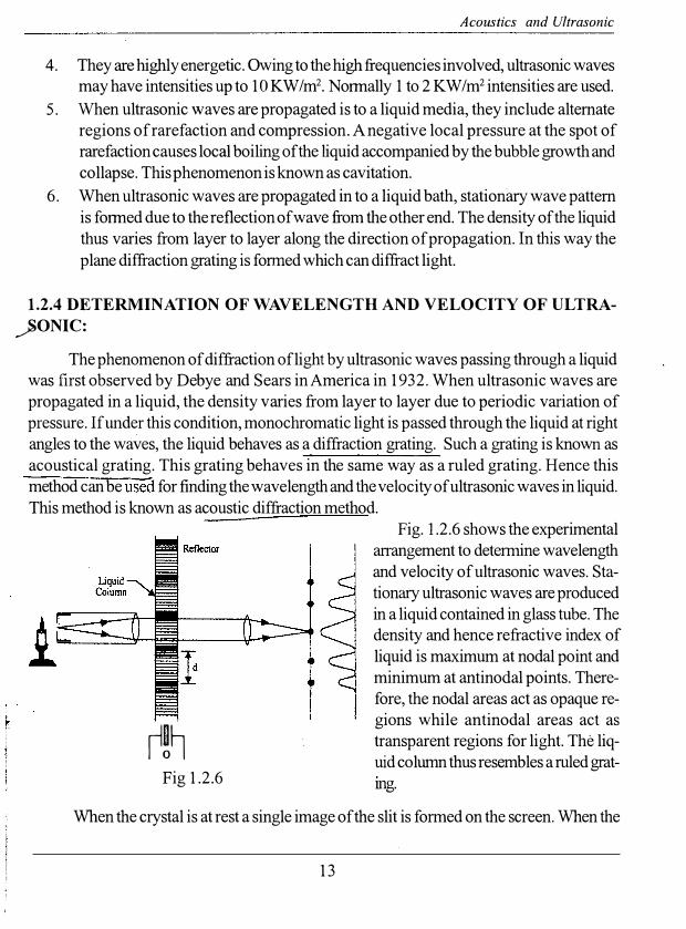
r!� Fig 1.2.6
Fig. 1.2.6 shows the experimental
arrangement to determine wavelength
and velocity of ultrasonic waves. Sta
tionary ultrasonic waves are produced
in a liquid contained in glass tube. The
density and hence refractive index of
liquid is maximum at nodal point and
minimum at antinodal points. There
fore, the nodal areas act as opaque re-
gions while antinodal areas act as
transparent regions for light. The liq
uid column thus resembles a ruledgrat
mg.
When the crystal is at rest a single image of the slit is formed on the screen. When the
13

Engineering Physics
crystal is excited a diffraction pattern is produced. It consists of a central maxima flanked by
1st order, 2nd order maxima and etc. the grating period d equals to � and is given 2
by
d sin9 =nA. (·: d = where Au- the wavelength of ultrasonic waves.
A - the wavelength of monochromatic light beam.
n - the order of the maxima.
2 d sin (} sin (} n ;t
.'. Au 2nJc sin(}
by knowing A and n and by measuring 9 the value ofA.u can be determined. The frequency
f of the waves is known from the frequency of the oscillator. The velocity of waves in the
liquid can be found out by the relation
v= fA.. u
APPLICATIONS OF ULTRASONICS: Ultrasonic are extensively used in industry, medicine and marine applications. We
study here some typical applications.
Transmitting transducer
R 0
A- Incident pulse
B- Pulse from flaw C - Re flee ted pulse
from bottom of specimen
Receiv1ng1 t ran sd u c e'r
Specimozn
Fig. 1.2.7
14
1. Detection of flaws in metal or non destructive testing:
The purpose of non destructive
testing is to find out whether any flaws exist
in a finished product without causing dam
age to the body. Ultrasonic waves can be
used to detect flaws in metal. We know
that flaw in the metal produces a change
in the medium due to which reflection of
ultrasonic waves takes place. Hence when
ultrasonic waves pass through a metal hav
ing some hole or crack inside it, an ap
preciable reflection occurs. The reflection

Acoustics and Ultrasonic
also takes place at the back surface of the metal. The reflected pulses are picked up by receiver and are suitably amplified. These pulses are now applied to one set of plates of cathode ray oscillograph. The transmitted signal and reflected signal from the flaw and back surface of metal produce a peak each. The position of the second perk on the time base of
oscillograph will give distance of flaw.
The experimental arrangement is shown in Fig. 1.2. 7. Here the transmitting transducer sends a beam of ultrasonic through the material under test. In the presence of flaw in the specimen, the waves will be reflected back and the corresponding recorded intensity in
the receiver will be very weak. Similarly, if there is a crack in the specimen, the transmitted
waves will have the intensity extremely small. The reflected beam is recorded by using cathode ray oscillograph (CRO).
2. Ultrasonic machining/drilling:
p � applications of ultrasonic waves. is a vibratory rocess which is now in co on use for the
mechanical treatment ofhard and brittle solids such as --
ceramics, glasses, precious stones, semiconductors and
hard alloys. The tool motion is produced by an acoustic concentrator to which the tool holder is threaded. The
acoustic concentrator consists of a needle type magnetostriction vibrator, illustrated in Fig. 1.2.8. The vibrator is made of thin isolated ferromagnetic plates of high magnetostriction such as nickel. A coil is wound on the needle, through which an alternating curent of frequency f passes. The resulting magnetic magnetizes the core and thus changes its length. The core of the vibrator vibrates at frequency 2 f. By choosing the frequency f to be equal to half the vibration frequency of the vibrator, the
Fig. 1.2.8 system is held at resonance as a result of which the vi-
brations ofthe needle will be oflarge amplitudes. A ta
pered waveguide of appropriate dimensions and rigidly attached to the vibrator concen
trates the vibrational energy and communicates to the tool. The tool oscillates linearly with
amplitude of0.013 to 0.1 mm at ultrasonic frequency of 20 KHz to 30KHz. In operation,
the needle vibrator is set in oscillation and the tool shank is pressed against the work piece.
15

Engineering Physics
An aqueous suspension of a solid abrasive powder is then fed through a tube to the working zone. Abrasive particles bombard the work surface at high velocity and shear off small pieces of the material. This action rapidly chips away the work piece in a pattern controlled by the tool shape and contour.
3. Ultrasonic Welding:
Practically, all metals and plastics can be welded using ultra�nic waves of suitable energy. The surfaces of the work pieces are cleaned and held together. They are subjected to ultrasonic oscillations at the spot where they are to be welded. The ultrasonic energy converts to heat at the contact area a result of friction arising between the surfaces. As the temperature of surface layers exceed the re-crystallization point, the layers melt and bond together to form a strong joint. The merits of this process are that it induces negligible stress at the spot of welding and that the structure of the materials remains unchanged.
4. Ultrasonic Soldering:
Normally, surfaces are covered with contaminants grease and oxide films. Such films prevent formation of a good joint. Therefore, prior to soldering the surfaces are cleaned with active fluxes. The fluxes, when heated, dissolve the oxide film and uncover the clean metal surfaces which readily allow the molten solder to forma firm joint. This method is however not suitable for soldering aluminum. Active metals such as aluminum can be soldered without fluxes with the help of ultrasonic waves. In this case soldering is done by a special iron which vibrates at a frequency of tens ofkilohertz. Ultrasonic waves can also be used for drilling and cutting processes in metals. These waves can also be used for soldering, for example, aluminum canot be soldered by normal methods. To solder aluminum ultrasonic wave along with electrical soldering iron is used. Ultrasonic welding can be done at room temperatures.
5. Ultrasonic Cleaning:
In the fabrication of electronic devices, it becomes highly essential to clean the surfaces of parts and components at different stages of production. Cleaning of the surfaces is commonly carried out in either organic solvents or weakly alkaline acqueous solutions containing surface active agents. To make the scrubbing of surfaces more effective, the phenomenon of cavitation is utilized. Ultrasonic cleaning baths are used for the purpose. The hydraulic shock arising at the surface of a part due to cavitation destroys any layer of contaminants. Bubbles penetrate under the layer, tear it off and break it down into minute pieces. The surface active agent pulls them away into the solution.
16

Acoustics and Ultrasonic
The chief advantage of this method is that it enables the surfaces of small products of intricate configuration. Jewelers use of ultrasonic baths to clean jewelry.
_)(.Echo Sounder:
- __ -_ -. _-- --=--
- =- -- - /IIIII
Fig. 1.2.9
..;:;. Sonar:
Ultrasonic waves can be produced in the fom1 of directed beams like beams oflight. Further, ultrasonic waves can travel long distances in water. As a result, ultrasound is widely used in marine applications. The depth of an ocean is determined using an echo sounder. The ship is equipped at its bottom with a source and a re
of ultrasound of a definite frequency. The source sends out short pulses of ultrasonic waves and the receiver receives reflected pulses. Measuring the time interval between pulse sent and the pulse received, the depth of the ocean can be computed with the help of the formula:
Depth I Distance vt
1 = ---------( 1) 2
The world sonar stands for sound navigation and ranging. The ultrasonic waves which arehighly directional can be used for locating objects and determining their distance in the seas. The idea of ultrasonic sonar was put forward first by the French Physicist Paul Langevin and was successfully by him during the first world war for detecting enemy submarines. The sonar acts in a way much similar to echo sounder. In the absence of an obstacle the ultrasonic pulses do not return to the ship. In the presence of an pulses are reflected and are picked up by the receiver. Knowing the speed of the ultrasound and elapsed time, the distance of the object can be determined using the formula (1 ) .
J-ish Finder:
Ultrasound can be used to locate shoals of fish, utilizing the fact that the swimming bladder of fish is filled with air which scatters ultrasonic waves. Ultrasonic sonar is used for this purpose. At present, ultrasonic locators are mainly used for detecting icebergs, fish shoals.
17

Engineering Physics
An interesting fact is that some animals have organs operating on the sonar principle.
For example, bats find their way in darkness and hunt for their prey using the sonar tech
niques. The bat emits a constant series of short ultrasonic pulses at a frequency of20 kHz to
60kHz. Its large ears are highly specialized to perceive these sounds and to determine the
direction and distance of objects from which the sounds are reflected. Some of the sea
animals such as whales and dolphins use ultrasound to locate their prey, avoid collision with
obstacles and even to converse with each other. In the depths of the sea, visibility is highly
restricted because of the strong absorption of light by water. It may be therefore that these
animals use ultrasound which is relatively less absorbed.
J· Formation of Alloys:
The constituents of alloys, having widely different densities, can be kept mixed uniformly by a beam of ultrasonic. Thus it is easy to get alloy of uniform composition.
10. Ultrasonic Mixing:
A colloid solution or emulsion of two non-miscible liquids like oil and water can be
formed by simultaneously subjecting to ultrasonic radiations. Now-a-days most of the emulsions like polishes, paints, food products and pharmaceutical preparations are prepared by
using ultrasonic mixing.
11. Coagulation and Crystallization:
The particles of suspended liquid, by ultrasonics, can be brought quite close to each other so that coagulation may take place. The crystallization rate is also affected by ultrasonics. The size of crystals, when molten metal is put to crystallization can be made smaller and more uniform by the use of ultrasonics.
12. Ultrasonic in Metallurgy:
To iradiate molten metals which are in the process of cooling so as to refine the grain
size and to prevent the formation of cores and to release trapped gases, the ultrasonic
waves are used.
� Cleaning and Clearing:
These waves can be used for cleaning utensils, washing clothes, removing dust and soot from the chimney.
18

le.
h
to
1e
�a
th
ly
;e
I-
e
y
1
Acoustics and Ultrasonic
14. Direction Signaling:
The ultrasonic waves can be concentrated into a sharp beam due to smaller wave
length and hence can be used for signaling in a particular direction.
�estruction of Lower Life:
The aninlals like rats, frogs, fishes etc. can be killed or injured by high intensity ultra
somes.
-tfreatment of Neuralgic Pain:
The body parts affected due to neuralgic or rheumatic pains on being exposed to
ultrasonics gets great relief from the pain.
Jif. Detection of Abnormal Growth:
Abnormal growth in the brain, certain tumors which canot be detected by X -rays
can be detected by ultrasonic waves.
*****
Question Bank
Objectives Type Questions Marks
1. List out essential features of good acoustics, according toW. C. 4
2 Explain the concept of reverberation and time of
reverberation in brief.
3 Define and explain in brief' Absorption coefficient'
4 List out various types of waves you know.
How will you differentiate them?
5 What is magnetostriction? Explain in brief.
6 What is piezoelectric effect? Explain in brief.
7 List out various properties of ultrasonic waves.
19
2each
4
3
4
4
4

Physics
Descriptive Type Questions or Notes
1 Explain in brief the magnetostliction method to generate ultrasonic waves.8
2 Explain in brief the piezoelectric method to generate ultrasonic waves. 8
3 How will you determine wavelength and velocity of ulti·asonic waves? 8
4 Write note on applications of ultrasonic waves.
5 Explain any four applications of ultrasonic waves in detail.
Numericals
8
8
Numericals will be asked based on articles such as: reverberation, time of
reverberation, Sabine's formula, absorption coefficient, determination of wave
length and velocity of ultrasonic waves etc.
****
20