acquity upc2 system guide...viii june 20, 2014, 715004521 rev. b audience and purpose this guide is...
TRANSCRIPT

ACQUITY UPC2
System Guide
715004521 / Revision B
Copyright © Waters Corporation 2014All rights reserved

Copyright notice
© 2014 WATERS CORPORATION. PRINTED IN THE UNITED STATES OF AMERICA AND IN IRELAND. ALL RIGHTS RESERVED. THIS DOCUMENT OR PARTS THEREOF MAY NOT BE REPRODUCED IN ANY FORM WITHOUT THE WRITTEN PERMISSION OF THE PUBLISHER.
The information in this document is subject to change without notice and should not be construed as a commitment by Waters Corporation. Waters Corporation assumes no responsibility for any errors that may appear in this document. This document is believed to be complete and accurate at the time of publication. In no event shall Waters Corporation be liable for incidental or consequential damages in connection with, or arising from, its use. For the most recent revision of this document, consult the Waters Web site (waters.com).
Trademarks
Waters, ACQUITY, ACQUITY UPLC, UPLC, Connections INSIGHT, Waters Quality Parts, Empower, MassLynx, UPC2, and “THE SCIENCE OF WHAT’S POSSIBLE.”are registered trademarks of Waters Corporation. ACQUITY UPC2and eCord are trademarks of Waters Corporation.
PEEK is a trademark of Victrex Corporation.
PharMed is a registered trademark of Saint-Gobain Performance Plastics.
Teflon is a registered trademark of E. I. du Pont de Nemours and Company.
Viton is a registered trademark of E. I. du Pont de Nemours and Company.
Other registered trademarks or trademarks are the sole property of their owners.
Customer comments
Waters’ Technical Communications organization invites you to report any errors that you encounter in this document or to suggest ideas for otherwise improving it. Help us better understand what you expect from our documentation so that we can continuously improve its accuracy and usability.
We seriously consider every customer comment we receive. You can reach us at [email protected].
ii June 20, 2014, 715004521 Rev. B

Contacting Waters
Contact Waters with enhancement requests or technical questions regarding the use, transportation, removal, or disposal of any Waters product. You can reach us via the Internet, telephone, or conventional mail.
Safety considerations
Some reagents and samples used with Waters instruments and devices can pose chemical, biological, or radiological hazards (or any combination thereof). You must know the potentially hazardous effects of all substances you work with. Always follow Good Laboratory Practice(GLP), and consult your organization’s standard operating procedures.
Safety hazard symbol notice
You must consult the appropriate documentation in all cases where the symbol appears to determine the nature of the potential hazard and any actions you must perform.
Waters contact information:
Contacting medium Information
Internet The Waters Web site includes contact information for Waters locations worldwide. Visit www.waters.com.
Telephone and fax From the USA or Canada, phone 800 252-4752, or fax 508 872 1990.For other locations worldwide, phone and fax numbers appear in the Waters Web site.
Conventional mail Waters Corporation34 Maple StreetMilford, MA 01757USA
June 20, 2014, 715004521 Rev. B iii

Considerations specific to the UPC2 system
The ACQUITY® UPC2™ (Ultra Performance Convergence Chromatography) system uses liquid CO2 collected from various industrial processes. Observe the following safety advisories that pertain to specific to the ACQUITY UPC2system and CO2.
Power cord replacement hazard
Hand crush hazard
High voltage hazard
CO2 hazards to humans
CO2 exhibits three primary hazards for humans:
• Frostbite from uncontrolled release of pressurized CO2 to atmosphere or contact with accumulated dry ice at a leak site.
• Asphyxiation caused by the displacement of oxygen.
Warning: To avoid electric shock, use the SVT-type power cord in the United States and HAR-type (or better) in Europe. The main power cord must only be replaced with one of adequate rating. For information regarding what cord to use in other countries, contact your local Waters distributor.
Warning: To avoid hazards associated with the reciprocating or rotating parts in the source, keep clear of the regions marked with yellow and gray labels.
Warning: To avoid electric shock, do not remove protective panels. The components they cover are not user-serviceable.
Warning: To prevent injury or death, install a CO2 Ambient Air Sensor/Alarm unit to ensure compliance with OSHA PEL for CO2 in locations where CO2 is used or stored, instead of or in addition to, an oxygen monitor. Monitors must be capable of detecting CO2 levels at a minimum of 5000 ppm or as required by your local regulating agency.
iv June 20, 2014, 715004521 Rev. B

Before proceeding with any monitoring safety configuration, consult with your environmental health and safety manager regarding applicable local, federal, and international safety regulations and requirements.
Bottle placement prohibition
FCC radiation emissions notice
Changes or modifications not expressly approved by the party responsible for compliance, could void the users authority to operate the equipment. This device complies with Part 15 of the FCC Rules. Operation is subject to the following two conditions: (1) this device may not cause harmful interference, and (2) this device must accept any interference received, including interference that may cause undesired operation.
Electrical power safety notice
Do not position the instrument so that it is difficult to operate the disconnecting device.
Equipment misuse notice
If the equipment is used in a manner not specified by the manufacturer, the protection provided by the equipment may be impaired.
Safety advisories
Consult Appendix A for a comprehensive list of warning advisories and notices.
Overview, maintenance, and safety information
Consult the following documentation for the ACQUITY UPC2 system located on the documentation CD.
Prohibited: To avoid injury from electric shock or fire, and to prevent damage to the workstation and ancillary equipment, do not place objects filled with liquid—such as solvent bottles—on these items, or expose them to dripping or splashing liquids.
June 20, 2014, 715004521 Rev. B v

Documentation for individual system modules:
UPC2 module Documentation
UPC2 photodiode array detector
The ACQUITY UPC2 Photodiode Array Detector Operator’s Overview and Maintenance Guide
Column manager and auxiliary column manager
The Column Compartment Operator’s Overview and Maintenance Guide
30-cm single-zone column manager
The ACQUITY 30-cm Single-Zone Column Manager Overview and Maintenance Guide
UPC2 sample manager - fixed loop
The ACQUITY UPLC Sample Manager - Fixed Loop Operator’s Overview and Maintenance Guide
UPC2 convergence chromatography manager
The ACQUITY UPC2 Convergence Manager Operator’s Overview and Maintenance Guide
UPC2 binary solvent manager
The ACQUITY UPC2 Binary Solvent Manager Operator’s Overview and Maintenance Guide
vi June 20, 2014, 715004521 Rev. B

Operating an ACQUITY UPC2 system
When operating an ACQUITY UPC2 system, follow standard quality-control (QC) procedures and the guidelines presented in this section.
Applicable symbols
Symbol Definition
Manufacturer
Date of manufacture
Authorized representative of the European Community
Confirms that a manufactured product complies with all applicable European Community directives
or
Australia EMC compliant
Confirms that a manufactured product complies with all applicable United States and Canadian safety requirements
Consult instructions for use
Supply ratings
June 20, 2014, 715004521 Rev. B vii

Audience and purpose
This guide is intended for personnel who operate and maintain the ACQUITY UPC2 system.
Intended use for an ACQUITY UPC2 system
The ACQUITY UPC2 system is intended only for research use. It is not intended for use in diagnostic or biologically hazardous applications. Use the system to perform normal phase separations in pharmaceutical development, discovery, and QA and QC environments, as well as, within the chemical materials, environmental, and food safety environments.
Calibrating
To calibrate LC systems, follow acceptable calibration methods using at least five standards to generate a standard curve. The concentration range for standards must include the entire range of QC samples, typical specimens, and atypical specimens.
Quality control
Routinely run three QC samples that represent subnormal, normal, and above-normal levels of a compound. Ensure that QC sample results fall within
Electrical and electronic equipment with this symbol may contain hazardous substances and should not be disposed of as general waste.For compliance with the Waste Electrical and Electronic Equipment Directive (WEEE) 2012/19/EU, contact Waters Corporation for the correct disposal and recycling instructions.
Serial number
Part number catalog number
Symbol Definition
���
viii June 20, 2014, 715004521 Rev. B

an acceptable range, and evaluate precision from day to day and run to run. Data collected when QC samples are out of range might not be valid. Do not report these data until you are certain that the instrument performs satisfactorily.
EMC considerations
Canada spectrum management emissions notice
This class A digital product apparatus complies with Canadian ICES-001.
Cet appareil numérique de la classe A est conforme à la norme NMB-001.
ISM Classification: ISM Group 1 Class B
This classification has been assigned in accordance with IEC CISPR 11 Industrial Scientific and Medical (ISM) instruments requirements. Group 1 products apply to intentionally generated and/or used conductively coupled radio-frequency energy that is necessary for the internal functioning of the equipment. Class B products are suitable for use in both commercial and residential locations and can be directly connected to a low voltage, power-supply network.
June 20, 2014, 715004521 Rev. B ix

EC authorized representative
Waters CorporationStamford AvenueAltrincham RoadWilmslow SK9 4AX UK
Telephone: +44-161-946-2400
Fax: +44-161-946-2480
Contact: Quality manager
x June 20, 2014, 715004521 Rev. B

Table of Contents
Copyright notice ................................................................................................... ii
Trademarks ............................................................................................................ ii
Customer comments ............................................................................................. ii
Contacting Waters ............................................................................................... iii
Safety considerations .......................................................................................... iii Safety hazard symbol notice.............................................................................. iii Considerations specific to the UPC2 system ..................................................... iv FCC radiation emissions notice .......................................................................... v Electrical power safety notice ............................................................................. v Equipment misuse notice .................................................................................... v Safety advisories .................................................................................................. v
Overview, maintenance, and safety information .......................................... v
Operating an ACQUITY UPC2 system ............................................................ vii Applicable symbols ........................................................................................... vii Audience and purpose...................................................................................... viii Intended use for an ACQUITY UPC2 system ................................................ viii Calibrating ....................................................................................................... viii Quality control ................................................................................................. viii
EMC considerations ............................................................................................ ix Canada spectrum management emissions notice ............................................. ix ISM Classification: ISM Group 1 Class B ......................................................... ix
EC authorized representative ........................................................................... x
1 ACQUITY UPC2 system .......................................................................... 15
Using ACQUITY UPC2 for normal-phase chromatography ..................... 15 Comparing supercritical fluid properties to those of other solvents............... 17
ACQUITY UPC2 system ..................................................................................... 17 ACQUITY UPC2 core system stack configurations and supported modules . 18
June 20, 2014, 715004521 Rev. B xi
Major components of the ACQUITY UPC2 system.......................................... 20
2 Preparing for operation ........................................................................ 25
Start the system hardware .............................................................................. 25 Before you start the system hardware.............................................................. 25
Starting the chromatography data software ............................................... 28 Starting the console ........................................................................................... 29
Priming and equilibrating the system .......................................................... 30 Priming the system............................................................................................ 30 Equilibrating the system................................................................................... 31
Observing the sample injection sequence .................................................... 31
Performing column screening ........................................................................ 38
Shutting down the ACQUITY UPC2 system ................................................. 39
3 Method parameters ................................................................................ 43
Creating methods in Empower software ...................................................... 43
Creating instrument methods for the UPC2 modules ............................... 43 ACQUITY UPC2 BSM instrument method settings........................................ 44 ACQUITY UPC2 sample manager instrument method settings..................... 44 ACQUITY column manager instrument method settings............................... 45 ACQUITY UPC2 convergence manager instrument method settings ............ 45 ACQUITY UPC2 PDA instrument method settings ........................................ 48
Creating methods in MassLynx software ..................................................... 48
4 External connections ............................................................................. 49
External connections ........................................................................................ 50
Connecting Ethernet cables ............................................................................ 51 Connecting external signal cables .................................................................... 52 Connecting the UPC2 PDA detector signal cables ........................................... 56
xii June 20, 2014, 715004521 Rev. B
Connecting the system to an electricity source ......................................... 56
5 Splitter configurations .......................................................................... 59
ACQUITY UPC2 splitter hardware components ......................................... 59 Core 1, 2, and 3 configuration splitter hardware components ........................ 60 Core 4 configuration splitter hardware components ....................................... 61 The ACQUITY ISM splitter .............................................................................. 62
Splitter bracket mount locations ................................................................... 64
Core 1 configuration: system diagrams and tubing connections ........... 68
Core 2 configuration: system diagrams and tubing connections ........... 76
Core 3 configuration: system diagrams and tubing connections ........... 80
Core 4 configuration: system diagrams and tubing connections ........... 88
6 Maintaining the ACQUITY UPC2 system ........................................... 97
Maintaining the ACQUITY UPC2 system modules ..................................... 97
Maintaining the automated backpressure regulator ................................ 98 Running an ABPR health test when the system includes a 30-cm single-zone
column manager .......................................................................................... 98
Spare parts ........................................................................................................ 100
Troubleshooting with Connections INSIGHT ........................................... 100
Safety and handling ........................................................................................ 102
A Safety advisories .................................................................................. 103
Warning symbols .............................................................................................. 103
Notices ................................................................................................................ 106
Warnings that apply to all Waters instruments and devices ................. 107
Warnings that address the replacing of fuses ........................................... 112
Electrical and handling symbols .................................................................. 114 Electrical symbols ............................................................................................ 114 Handling symbols ............................................................................................ 115
June 20, 2014, 715004521 Rev. B xiii

B Specifications ........................................................................................ 117
ACQUITY UPC2 system specifications ........................................................ 117
Solvents to use with liquid CO2 ........................................................................................ 120 Wetted materials ............................................................................................. 121
ACQUITY UPC2 binary solvent manager specifications ........................ 123
ACQUITY UPC2 convergence manager specifications ............................ 126
ACQUITY column manager with active preheating and auxiliary column manager specifications ............................................................................ 127
ACQUITY 30-cm single-zone column manager specifications ............... 129
ACQUITY UPC2 photodiode array detector specifications ................... 129
ACQUITY UPC2 sample manager - fixed loop specifications ................ 131
Physical specifications ................................................................................... 133
C Configuring the core 4 system variant ............................................ 135
Physical arrangement ..................................................................................... 136
Column configuration ..................................................................................... 137
Configuring software for dual column managers .................................... 138
xiv June 20, 2014, 715004521 Rev. B

Using ACQUITY UPC2 for normal-phase chromatography
1 ACQUITY UPC2 system
The ACQUITY UPC2 (Ultra Performance Convergence Chromatography) system uses liquid carbon dioxide (CO2) as the primary mobile phase for normal-phase, chiral, and achiral separations.
You control the system using the driver pack software that you access through one of these Waters’ data systems: Empower® software or MassLynx® software.
Using ACQUITY UPC2 for normal-phase chromatography
ACQUITY UPC2 chromatography is a normal-phase chromatographic technique that offers these advantages over traditional HPLC normal-phase chromatography:
• Uses liquid CO2, a chemically pure, stable, and nonpolar solvent, as the primary mobile phase.
• Combines liquid CO2 with one or more organic solvents, typically alcohols such as methanol and isopropanol, to increase the solvent strength for separating polar compounds.
• Minimizes health, safety, and environmental concerns associated with chemical solvents.
• Runs at higher flow rates (3 to 5 times higher than HPLC for the columns of the same dimension) because of its high diffusivity.
• Produces lower pressure drops across the column and faster separations, because of the mobile phases’s low viscosity.
Contents:
Topic Page
Using ACQUITY UPC2 for normal-phase chromatography.......... 15
ACQUITY UPC2 system.................................................................. 17
June 20, 2014, 715004521 Rev. B 15

1 ACQUITY UPC2 system
Pressure-temperature phase diagram for CO2:
Comparing supercritical fluid properties to those of other solvents
Supercritical CO2 fluid has a lower viscosity, higher diffusion rate, and no surface tension when compared to liquid CO2. Their supercritical CO2 physical properties are between those of liquids and gases. Diffusivities of solutes in supercritical CO2 are by as much as a factor of 10 higher than their diffusivities in liquid solvents. Because supercritical fluid properties are pressure-dependent near the critical point, they are highly tunable solvents.
Recommendation: Use only food-grade or better, liquid dip-tube or gas cylinder, or house supply CO2 at a flow pressure of 6,205 to 7,584 kPa (62 to 76 bar, 900 to 1100 psi).
Solvent viscosity comparison:
Solvent Viscosity range
Supercritical CO2 fluid 20-100 μPa.s (0.02-0.1 cP)
Liquids 500-1000 μPa.s (0.5-1.0 cP)
Gases 10 μPa.s (0.01 cP)
75 bar
Pre
ssur
e
Temperature
16 June 20, 2014, 715004521 Rev. B

ACQUITY UPC2 system
ACQUITY UPC2 system
The following illustrations show the four core configurations that comprise the ACQUITY UPC2 system. Your system configuration can differ according to the number and type of modules it contains. For example, if a system includes a mass spectrometer, the system modules can be arranged as two or three separate stacks.
ACQUITY UPC2 core system stack configurations and supported modules
Core 1 configuration:
�������
PDA
CM-A
Convergence manager
SM-FL
ccBSM
Side mount solvent tray
June 20, 2014, 715004521 Rev. B 17

1 ACQUITY UPC2 system
Core 2 configuration:
Core 3 configuration:
TP03523
Convergence manager
SM-FL
ccBSM
Solvent tray
PDA
CM-AUX
CM-A
TP03529
Solvent tray
SM-FL
ccBSM
PDA
CM-AUX
CM-A
CM-AUX
Convergence manager
18 June 20, 2014, 715004521 Rev. B

ACQUITY UPC2 system
Core 4 configuration:
See also: Appendix C for information about configuring a system with two CM-30S modules.
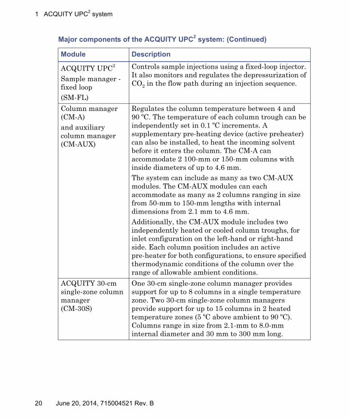
Major components of the ACQUITY UPC2 system
The following table describes the ACQUITY UPC2 system modules and their functions.
Major components of the ACQUITY UPC2 system:
Module Description
ACQUITY UPC2
Convergence manager
Regulates and monitors the incoming flow and pressure of liquid CO2 in the system through these mechanisms:• Electronically controlled CO2 inlet shutoff valve
• Overpressure protection• Auxiliary valve for venting the injection loop• Automated back pressure regulator (ABPR)
CM-30S
Solvent tray
Convergence manager
SM-FL
PDA
ccBSM
June 20, 2014, 715004521 Rev. B 19
1 ACQUITY UPC2 system
ACQUITY UPC2
Sample manager - fixed loop(SM-FL)
Controls sample injections using a fixed-loop injector. It also monitors and regulates the depressurization of CO2 in the flow path during an injection sequence.
Column manager (CM-A)and auxiliary column manager (CM-AUX)
Regulates the column temperature between 4 and 90 ºC. The temperature of each column trough can be independently set in 0.1 ºC increments. A supplementary pre-heating device (active preheater) can also be installed, to heat the incoming solvent before it enters the column. The CM-A can accommodate 2 100-mm or 150-mm columns with inside diameters of up to 4.6 mm. The system can include as many as two CM-AUX modules. The CM-AUX modules can each accommodate as many as 2 columns ranging in size from 50-mm to 150-mm lengths with internal dimensions from 2.1 mm to 4.6 mm.Additionally, the CM-AUX module includes two independently heated or cooled column troughs, for inlet configuration on the left-hand or right-hand side. Each column position includes an active pre-heater for both configurations, to ensure specified thermodynamic conditions of the column over the range of allowable ambient conditions.
ACQUITY 30-cm single-zone column manager(CM-30S)
One 30-cm single-zone column manager provides support for up to 8 columns in a single temperature zone. Two 30-cm single-zone column managers provide support for up to 15 columns in 2 heated temperature zones (5 ºC above ambient to 90 ºC). Columns range in size from 2.1-mm to 8.0-mm internal diameter and 30 mm to 300 mm long.
Major components of the ACQUITY UPC2 system: (Continued)
Module Description
20 June 20, 2014, 715004521 Rev. B

ACQUITY UPC2 system
Waste collection containers
Use only waste collection containers required by your local regulating agency with the ACQUITY UPC2 system.
ACQUITY UPC2
Binary solvent manager(ccBSM)
Under Empower, or MassLynx software control, the pump’s A side actively chills the CO2 fluid pumped into the system, while the pump’s B side can pump any one of four cosolvents. The pump operates at flow rates up to 4mL/minute and pressures up to 41,369 kPa (413 bar, 6000 psi).
ACQUITY UPC2
Photodiode array (PDA) detector
Incorporates 10-mm stainless steel flow cells that can withstand pressures as high as 41,369 kPa (413 bar, 6000 psi). Updated lens material improves sensitivity and performance. Reduced internal volume in the flow cell minimizes dispersion within the cell.
Side-mounted solvent tray
Provides easy access to the solvent bottles in an ACQUITY UPC2 system.
Top-mounted solvent tray
The optional top-mounted solvent tray is available for configurations of four or fewer modules in a stack.
Warning: To avoid serious injury never use a glass waste container with an ACQUITY UPC2 system because it can burst in the event of over-pressure conditions.
Notice: To avoid fluid backup, ensure proper drainage of waste:• Place the waste container below the system stack.• Ensure the waste tube does not crimp or bend. A crimp or bend can
impede flow to the waste container.• Ensure the exit of the waste tube is not immersed in waste solvent. If
necessary, shorten the tube so that no portion of it drops below the top of the waste container.
Major components of the ACQUITY UPC2 system: (Continued)
Module Description
June 20, 2014, 715004521 Rev. B 21
1 ACQUITY UPC2 system
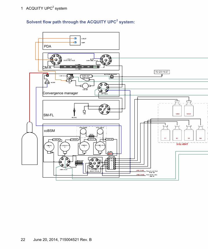
Solvent flow path through the ACQUITY UPC2 system:
PDA
CM-A
SM-FL
Convergence manager
ccBSM
22 June 20, 2014, 715004521 Rev. B

ACQUITY UPC2 system
June 20, 2014, 715004521 Rev. B 23

1 ACQUITY UPC2 system
24 June 20, 2014, 715004521 Rev. B
Start the system hardware
2 Preparing for operation
For normal-phase separations using the ACQUITY UPC2 system, you can use higher pressures (from 10,342 to 41,369 kPa, 103 to 413 bar, 1500 to 6000 psi) and temperatures ranging from 4º C to 90º C.
Perform the tasks in this section to prepare the system for use.
Prerequisite: Make sure you have performed all procedures in the module overview and maintenance guides in the preparing for operation sections before proceeding.
Start the system hardware
The system hardware can include the UPC2® instrument modules, UPC2 PDA, ELSD, or SQD/TQD detectors, 515 pump, pump controller module, QDa and ISM. A workstation computer is required to run the data system software and to configure and control system functions through the console user interface.
Before you start the system hardware
Verify that all fittings are properly tightened, to prevent leaks. Preventing leaks ensures that the system maintains adequate pressure, temperature, and sample integrity throughout an analysis.
Contents:
Topic Page
Start the system hardware.............................................................. 25
Starting the chromatography data software .................................. 28
Priming and equilibrating the system ............................................ 30
Observing the sample injection sequence ....................................... 31
Performing column screening.......................................................... 38
Shutting down the ACQUITY UPC2 system.................................. 39
June 20, 2014, 715004521 Rev. B 25

2 Preparing for operation
To turn on the CO2 supply to the system
Slowly open the large valve on the supply, and inspect the fitting for leaks.
To inspect the system for leaks
Leaks can occur at any tubing connection, gasket, or seal. Most often, however, they occur at tubing connections.
When required, tighten system fittings according to the features set forth in the in the overview and maintenance guides for each instrument. The techniques used to retighten fittings differ from those used to install fittings for the first time.
To start the system hardware:
1. Start the ACQUITY UPC2 workstation computer.
Requirement: Before you power-on the detector, prime the system to fill the flow cell with solvent and remove any air.
See also: “Priming and equilibrating the system”. Also see The ACQUITY UPC2 Photodiode Array Detector Overview and Maintenance Guide for more information on the PDA detector flow cell.
2. Press the power button to start all system modules operating.
See also: “Set a primary and secondary column manager” for more information on configuring a system with two column managers.
Requirement: When you power-on your system hardware, you must press the power button on the secondary column manager first, followed by the primary column manager second.
Workaround: To reset software, right click on a control panel and select reset or click reset on the control menu item in the console instrument page.
3. Observe the LED indicator on the right-hand side on each module to determine its operational status.
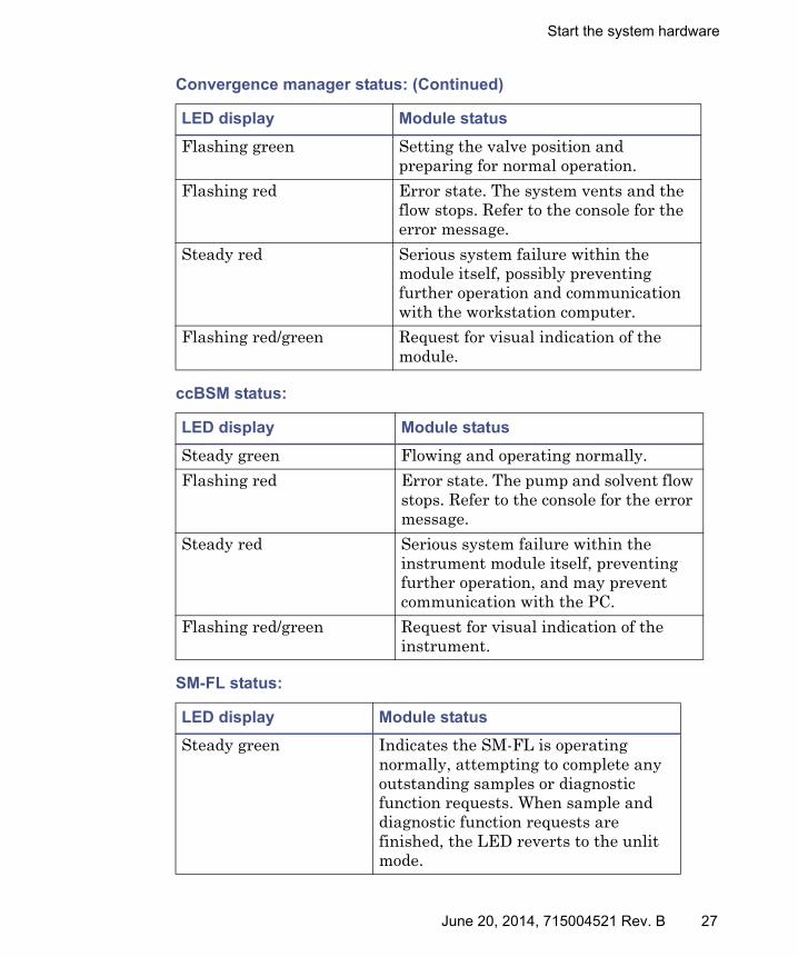
Convergence manager status:
LED display Module status
Steady green Liquid CO2 is on.
26 June 20, 2014, 715004521 Rev. B
Start the system hardware
Flashing green Setting the valve position and preparing for normal operation.
Flashing red Error state. The system vents and the flow stops. Refer to the console for the error message.
Steady red Serious system failure within the module itself, possibly preventing further operation and communication with the workstation computer.
Flashing red/green Request for visual indication of the module.
ccBSM status:
LED display Module status
Steady green Flowing and operating normally.
Flashing red Error state. The pump and solvent flow stops. Refer to the console for the error message.
Steady red Serious system failure within the instrument module itself, preventing further operation, and may prevent communication with the PC.
Flashing red/green Request for visual indication of the instrument.
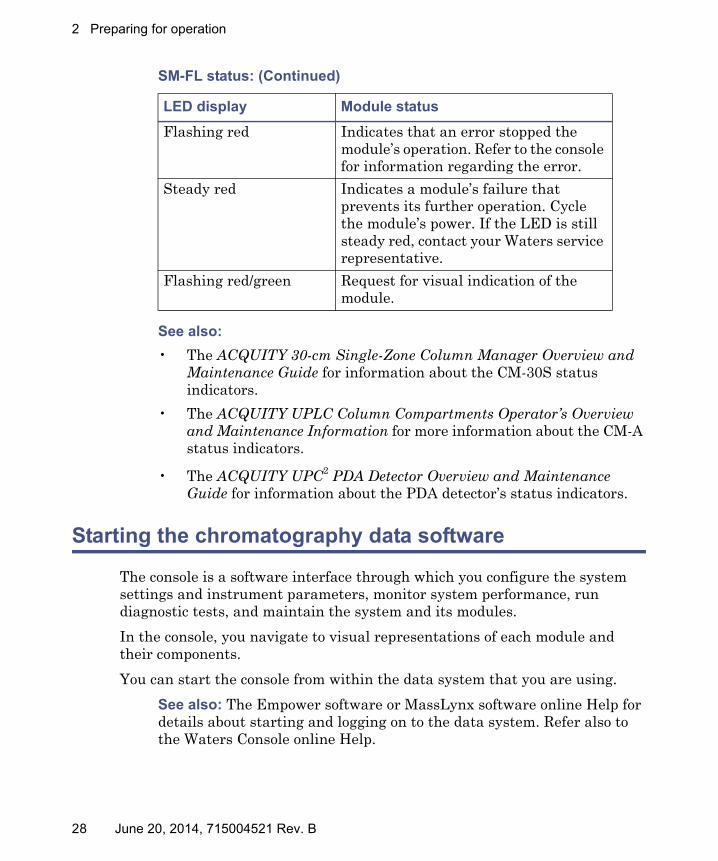
SM-FL status:
LED display Module status
Steady green Indicates the SM-FL is operating normally, attempting to complete any outstanding samples or diagnostic function requests. When sample and diagnostic function requests are finished, the LED reverts to the unlit mode.
Convergence manager status: (Continued)
LED display Module status
June 20, 2014, 715004521 Rev. B 27
2 Preparing for operation
See also:
• The ACQUITY 30-cm Single-Zone Column Manager Overview and Maintenance Guide for information about the CM-30S status indicators.
• The ACQUITY UPLC Column Compartments Operator’s Overview and Maintenance Information for more information about the CM-A status indicators.
• The ACQUITY UPC2 PDA Detector Overview and Maintenance Guide for information about the PDA detector’s status indicators.
Starting the chromatography data software
The console is a software interface through which you configure the system settings and instrument parameters, monitor system performance, run diagnostic tests, and maintain the system and its modules.
In the console, you navigate to visual representations of each module and their components.
You can start the console from within the data system that you are using.
See also: The Empower software or MassLynx software online Help for details about starting and logging on to the data system. Refer also to the Waters Console online Help.
Flashing red Indicates that an error stopped the module’s operation. Refer to the console for information regarding the error.
Steady red Indicates a module’s failure that prevents its further operation. Cycle the module’s power. If the LED is still steady red, contact your Waters service representative.
Flashing red/green Request for visual indication of the module.
SM-FL status: (Continued)
LED display Module status
28 June 20, 2014, 715004521 Rev. B
Starting the chromatography data software
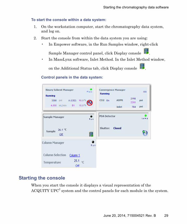
To start the console within a data system:
1. On the workstation computer, start the chromatography data system, and log on.
2. Start the console from within the data system you are using:
• In Empower software, in the Run Samples window, right-click
Sample Manager control panel, click Display console .
• In MassLynx software, Inlet Method. In the Inlet Method window,
on the Additional Status tab, click Display console .
Control panels in the data system:
Starting the console
When you start the console it displays a visual representation of the ACQUITY UPC2 system and the control panels for each module in the system.
June 20, 2014, 715004521 Rev. B 29
2 Preparing for operation
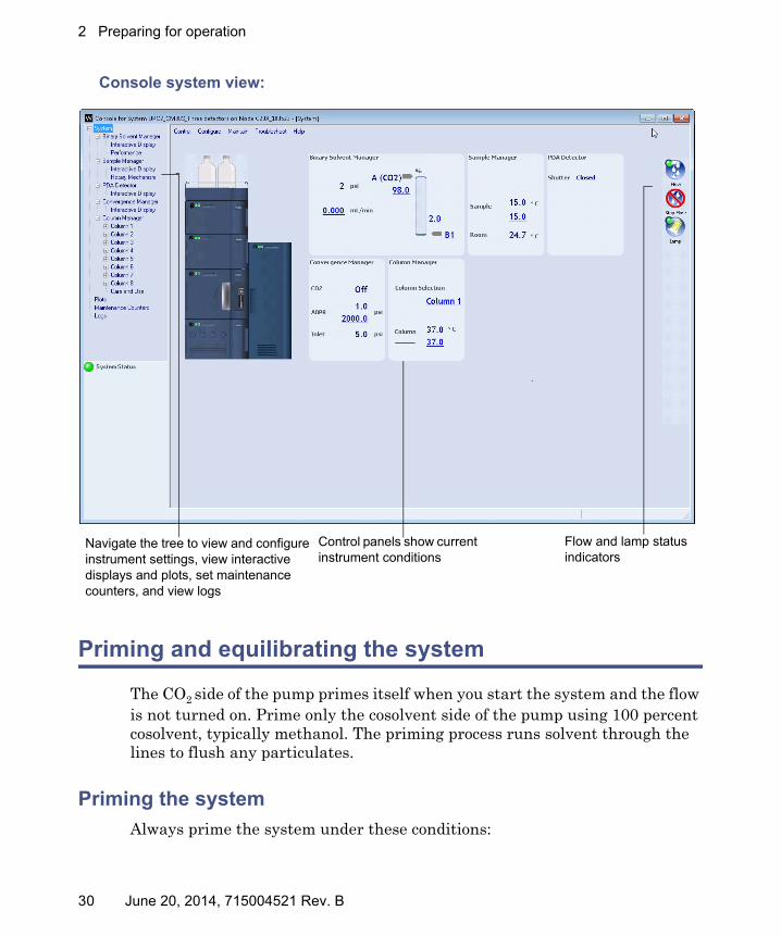
Console system view:
Priming and equilibrating the system
The CO2 side of the pump primes itself when you start the system and the flow is not turned on. Prime only the cosolvent side of the pump using 100 percent cosolvent, typically methanol. The priming process runs solvent through the lines to flush any particulates.
Priming the system
Always prime the system under these conditions:
Navigate the tree to view and configure instrument settings, view interactive displays and plots, set maintenance counters, and view logs
Flow and lamp status indicators
Control panels show current instrument conditions
30 June 20, 2014, 715004521 Rev. B

Observing the sample injection sequence
• After replacing the needle.
• When the system has been idle for a relatively long time, such as overnight.
• During system startup.
• When changing cosolvent.
Equilibrating the system
Equilibrating the system involves setting the conditions for the method you plan to run for your analysis. For example, setting the flow rate, solvent composition, column temperature, ABPR pressure and other such conditions.
See: The ACQUITY UPC2 Binary Solvent Manager Operator’s Overview and Maintenance Guide for details about priming and equilibrating the system. Also see the ACQUITY online Help.
Observing the sample injection sequence
The following diagrams illustrate the sample set up and injection sequence in an ACQUITY UPC2 system.
June 20, 2014, 715004521 Rev. B 31

2 Preparing for operation
Step 1: Sample manager runs internal setup tests and decompresses the sample loop:
At the start of an injection, the injection valve is in the “inject” position (from the previous injection). The SM-FL signals the auxiliary valve to turn 60° to the “load” position, to enable the connecting tubes from the 2 valves to vent to atmosphere (including the sample loop on the injection valve).
Waste Waste
Auxiliary valve (load position)
Metering syringeInjection valve (inject position)Sample
Liquid mobile phase (CO2)
Gas mobile phase (CO2)
Air gap
Buffer volume
Sample
Weak wash
From pump To column
Sample loop
32 June 20, 2014, 715004521 Rev. B
Observing the sample injection sequence
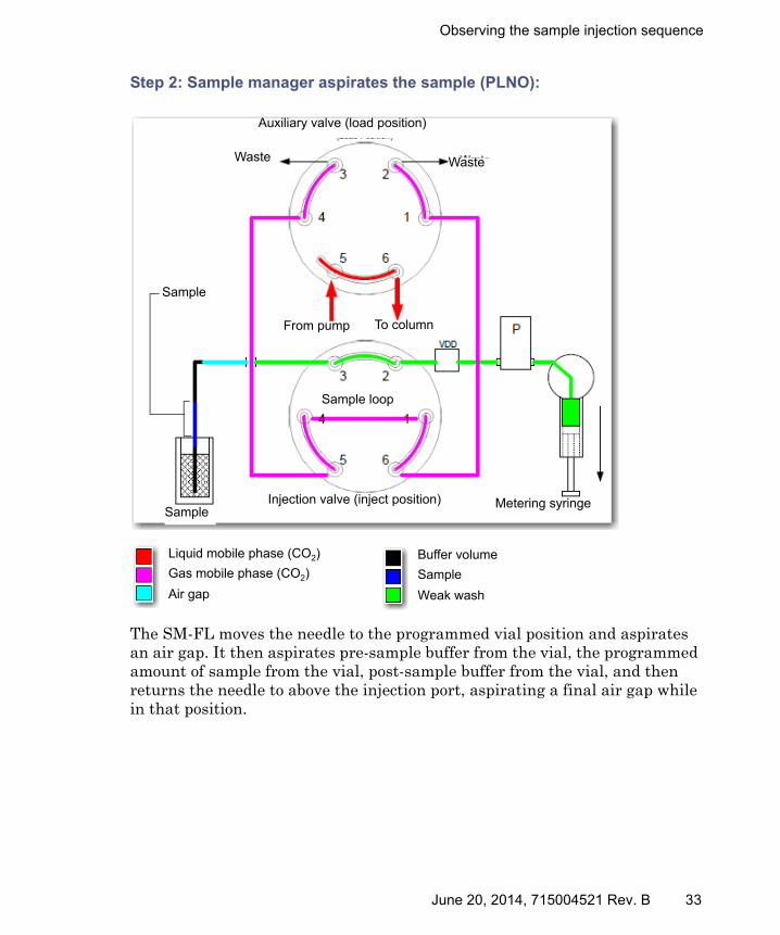
Step 2: Sample manager aspirates the sample (PLNO):
The SM-FL moves the needle to the programmed vial position and aspirates an air gap. It then aspirates pre-sample buffer from the vial, the programmed amount of sample from the vial, post-sample buffer from the vial, and then returns the needle to above the injection port, aspirating a final air gap while in that position.
Auxiliary valve (load position)
Waste Waste
Metering syringeInjection valve (inject position)Sample
Liquid mobile phase (CO2)
Gas mobile phase (CO2)
Air gap
Buffer volume
Sample
Weak wash
From pump To column
Sample loop
Sample
June 20, 2014, 715004521 Rev. B 33

2 Preparing for operation
Step 3: Metering syringe repositions the sample:
When the needle is over the injection port, the metering syringe pulls the sample aliquot past port 2 of the injection valve and into the VDD tubing.
Waste Waste
Auxiliary valve (load position)
Metering syringeInjection valve (inject position)Sample
From pump To column
Sample loop
Liquid mobile phase (CO2)
Gas mobile phase (CO2)
Air gap
Buffer volume
Sample
Weak wash
Sample
34 June 20, 2014, 715004521 Rev. B

Observing the sample injection sequence
Step 4: Metering syringe positions the sample in the sample loop:
The injection valve rotates into the load position. The metering syringe loads the programmed sample volume into the sample loop.
Waste Waste
Auxiliary valve (load position)
Metering syringeInjection valve (Load position)Sample
Liquid mobile phase (CO2)
Gas mobile phase (CO2)
Air gap
Buffer volume
Sample
Weak wash
From pump To column
Sample loopSample
June 20, 2014, 715004521 Rev. B 35

2 Preparing for operation
Step 5: Injection valve moves to the inject position:
The injection valve rotates to the inject position and places sample in line with the connecting tubes between the auxiliary valve and the injection valve.
Waste Waste
Auxiliary valve (load position)
Metering syringeInjection valve (inject position)Sample
Liquid mobile phase (CO2)
Gas mobile phase (CO2)
Air gap
Buffer volume
Sample
Weak wash
From pump To column
Sample loopSample
36 June 20, 2014, 715004521 Rev. B

Observing the sample injection sequence
Step 6: Auxiliary valve introduces sample into the liquid CO2 system:
The auxiliary valve rotates to the inject position and allows mobile phase to pass through the injection valve. This introduces sample into the high pressure liquid CO2 system, and injects the sample onto the column.
Waste Waste
Auxiliary valve (inject position)
Metering syringeInjection valve (inject position)Sample
Liquid mobile phase (CO2)
Gas mobile phase (CO2)
Air gap
Buffer volume
Sample
Weak wash
From pump To column
Sample loop
Sample
June 20, 2014, 715004521 Rev. B 37

2 Preparing for operation
Step 7: The sample manager washes the outside and inside of the needle:
With the injection and auxiliary valves in the inject position, after injecting the sample, the SM-FL washes the outside and inside of the sample needle. The wash syringes dispense the programmed amount of strong and weak washes through a single trace in the injection valve and out through the needle.
Performing column screening
Before running separations, best practice requires that you first screen the various UPC2 column chemistries, to determine the most suitable one to use for the compounds you want to separate.
Waste Waste
Auxiliary valve (inject position)
Injection valve (inject position)Sample
Liquid mobile phase (CO2)
Gas mobile phase (CO2)
Air gap
Buffer volume
Sample
Weak wash
From pump To column
Sample loop
Metering syringe
Wash syringes
38 June 20, 2014, 715004521 Rev. B

Shutting down the ACQUITY UPC2 system
A typical column screening workflow involves these actions:
• Create a method for each column that you want to screen.
• In each method, create a gradient consisting of two or three injections. Specify the first injection, to equilibrate the column, and the second and third injections, to inject the sample.
• Run the gradient for 5 minutes, starting with a mobile phase mixture of 5% organic solvent and 95% CO2, and ending with a maximum of 40% organic solvent and 60% CO2.
• Run the 40% organic solvent for at least 1 minute to wash the column.
Recommendation: Start with methanol as your cosolvent. If the column does not achieve a separation, you can use weaker solvents such as ethanol or isopropanol.
• Set the system parameters:
• Flow rate from 2.5 mL/minute for a 3.0 × 100-mm ID, sub-2 μm column.
Exception: For smaller ID columns and smaller particle sizes, use lower flow rates.
• Column temperature above the minimum 31° C.
• System pressure above 9997 kPa (100 bar, 1450 psi).
Tip: A good starting point system pressure is 11,996 kPa (120 bar, 1740 psi).
• ABPR pressure set to 13,789 kPa (138 bar, 2000 psi)
After you review the data and choose the column best suited for your application, you can run an isocratic method or a shallow gradient to further optimize your method.
Shutting down the ACQUITY UPC2 system
To shut down the ACQUITY UPC2 system for less than 24 hours:
1. Pump the initial mobile phase mixture through the column.
Result: Doing so maintains the column equilibrium necessary for good retention time reproducibility.
June 20, 2014, 715004521 Rev. B 39

2 Preparing for operation
2. To lengthen lamp life, extinguish the detector lamp by clicking Lamp Off in the detector control panel.
Tip: If you are running under MassLynx control, ensure that Auto-Shutdown for your shutdown method is deactivated.
3. If the next injection is not for several hours, slow the flow rate in the interim to approximately 0.3 mL/min to conserve solvent.
Tip: Ensure that the shutdown method is deactivated.
4. Ensure the detector is operating and the column compartment is at operating temperature during this period.
To shut down the ACQUITY UPC2 system for more than 24 hours:
1. Extinguish the detector lamp by clicking Lamp Off in the detector control panel.
2. Remove buffer salts and additives by flushing the system with water.
3. Flush the column and flow cell with 100% pure organic solvent.
Note: The system must remain in 100% CO2 at end of operation and during shutdown overnight to prevent column failure.
4. If the system includes:
• a column manager; in its method editor, select “Shut down all columns”, to override all temperature settings.
• a CM-30S; select Off for the temperature setting.
5. Power-off the detector.
6. Stop the solvent flow to vent the system:
• From the console, select ACQUITY UPC2 Binary Solvent Manager in the system tree.
Warning: To avoid electric shock, set a system instrument's power switch to Off, and then unplug the instrument’s power cord from the AC outlet, which completely interrupts power. The power switch on each system instrument controls the basic operational state of that instrument. Nevertheless, some instrument circuits remain live after the instrument is switched off.
40 June 20, 2014, 715004521 Rev. B
Shutting down the ACQUITY UPC2 system
• Enter zero flow in the composition field or press the Stop Flow icon and enter a flow rate of zero. The system will vent to atmospheric pressure through the vent valve in the ACQUITY UPC2 Convergence Manager.
7. Power-off the system.
Alternatives:
• If you prefer to leave the system powered-on, turn off the column compartment or reduce its temperature to 40° C.
• Create a system shutdown method.
Before using any system or instruments that have been shut down, under the recommended conditions, ensure that the new mobile phase is miscible with the recommended storage solvents: water/methanol or water/acetonitrile. If the mobile phase and solvents for the new analysis are not directly miscible with the recommended storage solvents –use an intermediate solvent, one that is miscible with both the storage solvents and those for the new analysis– to flush the storage solvents from the system and all of its components.
Warning: To avoid burn injuries resulting from skin contact with pressurized, liquid CO2 and breathing difficulties caused by the displacement of oxygen within the confines of the laboratory space, stop the solvent flow, and vent the system pressure before you attempt to maintain ACQUITY UPC2 systems.
June 20, 2014, 715004521 Rev. B 41

2 Preparing for operation
42 June 20, 2014, 715004521 Rev. B

3 Method parameters
Creating methods for UPC2 normal-phase chromatography is similar to creating them for HPLC normal-phase chromatography. The only difference is that you replace your mobile phase organic solvents with liquid CO2.
Creating methods in Empower software
In Empower software, you first create an instrument method in a method set to specify your instrument parameters. Create a processing method to specify how you want to process and view the results.
See also: The “Getting Started” section in the Empower software online Help, the topic “Using a quick-start guided tour to learn about Empower”. Click on the Empower Quick Start Tour link. Also see the topics in the “Define Methods” section in the Empower software online Help.
Creating instrument methods for the UPC2 modules
Configure an instrument method for each of the following ACQUITY UPC2 system modules that are part of your system:
• ccBSM
• SM-FL
• CM-A or CM-30S
Contents:
Topic Page
Creating methods in Empower software ........................................ 43
Creating instrument methods for the UPC2 modules ................... 43
Creating methods in MassLynx software ....................................... 48
June 20, 2014, 715004521 Rev. B 43
3 Method parameters
• Convergence manager
• PDA
• Mass spectrometers
ACQUITY UPC2 BSM instrument method settings
Follow these guidelines when setting up a method for the ACQUITY UPC2 binary solvent manager:
• Flow rate range is 0.010 to 4.000 mL/min.
• Maximum pressure is 41,369 kPa (414 bar, 6000 psi) up to 3.25 mL/min.
• Linear decrease to 29,303 kPa (293 bar, 4250 psi) at flow rates up to 4.00 mL/min.
• Solvent A is always liquid CO2.
• Solvent B can be one of four cosolvents.
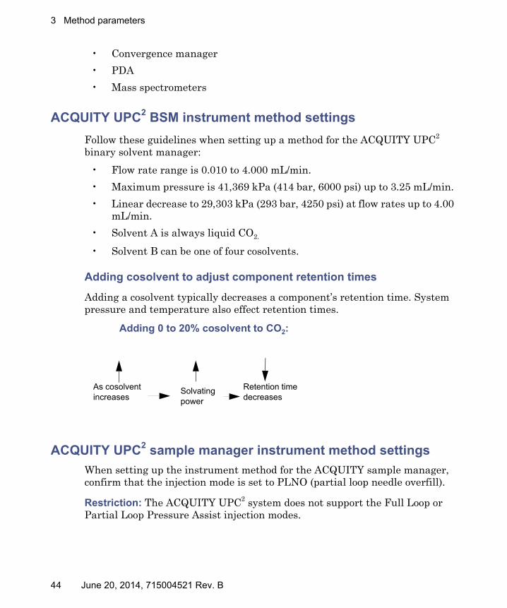
Adding cosolvent to adjust component retention times
Adding a cosolvent typically decreases a component’s retention time. System pressure and temperature also effect retention times.
ACQUITY UPC2 sample manager instrument method settings
When setting up the instrument method for the ACQUITY sample manager, confirm that the injection mode is set to PLNO (partial loop needle overfill).
Restriction: The ACQUITY UPC2 system does not support the Full Loop or Partial Loop Pressure Assist injection modes.
Adding 0 to 20% cosolvent to CO2:
As cosolvent increases
Solvating power
Retention time decreases
44 June 20, 2014, 715004521 Rev. B

Creating instrument methods for the UPC2 modules
Recommendation: Use your weak wash solvent, or a solvent weaker than the weak wash solvent, as the cosolvent.
When choosing a sample diluent, follow these guidelines:
• Do not dilute a sample in 100% methanol or similar strong solvent. Doing so can cause retention-time problems, selectivity problems, and split peaks.
• Dilute samples in heptane or similar weak solvents, instead of methanol.
• You can use as much as 20% methanol with heptane.
• Do not use water as the sample diluent or wash solvent.
ACQUITY column manager instrument method settings
The minimum and maximum temperature settings vary among different components. When configuring the instrument settings for an ACQUITY column manager in an ACQUITY UPC2 system, follow this general guideline.
• Maintain UPC2 column-heating temperature between ambient and 60° C.
ACQUITY UPC2 convergence manager instrument method settings
The convergence manager sets the automated back pressure regulator (ABPR) to prevent the mobile phase from phase separation. The minimum back pressure to maintain CO2 in a liquid state is 7,584 kPa (75 bar, 1100 psi).
Note: The minimum back pressure setting is 10,342 kPa (103 bar, 1500 psi).
Setting up a pressure gradient
Some classes of compounds require the use of 100% liquid CO2 to elute off the column. When using 100% liquid CO2, you can set up a pressure gradient to increase the solvent strength (density) of the liquid CO2, which is similar to setting up a solvent gradient to increase solvent strength.
Notice: To prevent damage to the needle, do not use the Cycle Injection Valve function in the Method Editor Events table for UPC2.
June 20, 2014, 715004521 Rev. B 45

3 Method parameters
Pressure gradient example:
46 June 20, 2014, 715004521 Rev. B

Creating instrument methods for the UPC2 modules
When setting pressure gradients, observe these guidelines:
• Higher ABPR pressures increase density and decrease retention times.
• Lower ABPR pressures decrease density and increase retention times.
ABPR pressure
ABPR pressure
Retention time
Longer retention time
Shorter retention time
CO2 No pressure range left to allow for a pressure drop across the column
June 20, 2014, 715004521 Rev. B 47

3 Method parameters
ACQUITY UPC2 PDA instrument method settings
The instrument settings parameters available for the UPC2 PDA are identical to those for the PDA detector.
See also: The console online Help for more information.
Creating methods in MassLynx software
If you are using MassLynx software, you create an inlet method to use in conjunction with an inlet system, such as an ACQUITY UPC2 system.
To create an inlet method in MassLynx, click the Instrument area in the MassLynx main window. Specify the pump, autosampler, and detector that you are using, and then configure the settings you want to use to acquire data.
Notes:
• When specifying column managers, note that they are configured as detectors.
• Waters pump control must be configured as the pump when the ccBSM, ISM or 515 makeup pump is used.
• You create methods offline. During offline method creation, all possible column positions, temperature set zones and external valve positions are available. An error message displays if you create a method that calls for a feature that does not exist in the current configuration.
See also:
• The MassLynx software online Help.
48 June 20, 2014, 715004521 Rev. B

4 External connections
A Waters Technical Service representative unpacks and installs your ACQUITY UPC2 system modules.
See also: The ACQUITY UPC2 System Site Preparation Guide.
Requirements:
• Contact Waters’ Technical Service department before moving the ACQUITY UPC2 system modules.
• If you must transport a system component, or remove it from service, contact Waters’ Technical Service department for recommended cleaning, flushing, and packaging procedures.
The information in this chapter explains how to connect the power cables, Ethernet cables, and external input/output cables on the rear panels of the system modules.
Warning: To avoid back injuries, do not attempt to lift the system modules without assistance.
Contents:
Topic Page
External connections........................................................................ 50
Connecting Ethernet cables............................................................. 51
Connecting the system to an electricity source .............................. 56
June 20, 2014, 715004521 Rev. B 49
4 External connections
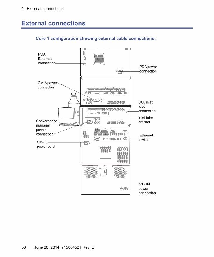
External connections
Core 1 configuration showing external cable connections:
TP03459
PDA power connection
Ethernet switch
PDA Ethernet connection
CO2 inlet tube connection
Inlet tube bracket
ccBSM power connection
CM-A power connection
Convergence manager power connection
SM-FL power cord
50 June 20, 2014, 715004521 Rev. B

Connecting Ethernet cables
Connecting Ethernet cables
The SM-FL includes an internal 10/100/1000 megabit Ethernet switch that accommodates the PC (workstation) and as many as 6 ACQUITY UPC2 system modules. Connect the shielded Ethernet cables from each module to the electronic connections on the rear panel of the SM-FL. The SM-FL is connected internally to the Ethernet switch.
Tip: If you are running more than 6 modules in addition to the SM-FL, use a Waters Ethernet switch box.
Required materials
• 9/32-inch nut driver
• Flat-blade screwdriver
• Connector
• Signal cable
Warning: To avoid electric shock, always disconnect system power before connecting or disconnecting external cables.
June 20, 2014, 715004521 Rev. B 51
4 External connections
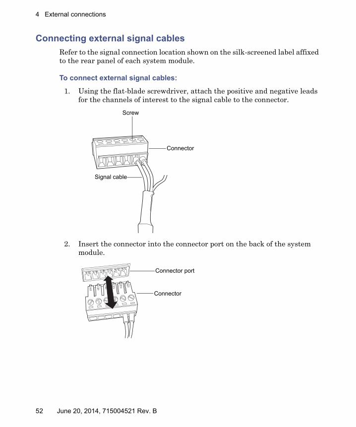
Connecting external signal cables
Refer to the signal connection location shown on the silk-screened label affixed to the rear panel of each system module.
To connect external signal cables:
1. Using the flat-blade screwdriver, attach the positive and negative leads for the channels of interest to the signal cable to the connector.
2. Insert the connector into the connector port on the back of the system module.
Signal cable
Screw
Connector
Connector
Connector port
52 June 20, 2014, 715004521 Rev. B
Connecting Ethernet cables
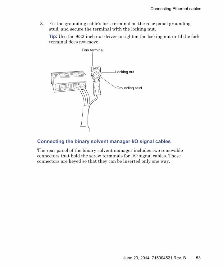
3. Fit the grounding cable’s fork terminal on the rear panel grounding stud, and secure the terminal with the locking nut.
Tip: Use the 9/32-inch nut driver to tighten the locking nut until the fork terminal does not move.
Connecting the binary solvent manager I/O signal cables
The rear panel of the binary solvent manager includes two removable connectors that hold the screw terminals for I/O signal cables. These connectors are keyed so that they can be inserted only one way.
Fork terminal
Locking nut
Grounding stud
June 20, 2014, 715004521 Rev. B 53

4 External connections
Binary solvent manager analog-out/event-in signal connectors:
For electrical specifications, see the ACQUITY UPC2 System Specifications Guide.
Binary solvent manager analog-out/event-in connections:
Signal connection Description
Auxiliary 1 In Reserved for future use.
Auxiliary 2 In Reserved for future use.
Run Stopped Out Indicates (with a contact closure) the binary solvent manager has ceased operation because of an error condition or operator request.
Switch 1 Out Reserved for future use.
0−2V Analog 1 Out Reserved for future use.
Gradient In Initiates the pumps to begin gradient operation by contact closure input or 0-volt input.
Stop Flow In Stops the flow from the binary solvent manager when an error condition or hardware failure occurs on another system module.
Connector I Connector II
1
2
3
4
5
6
7
8
9
10
11
12
+−+−
+−
Auxiliary 1 In
Auxiliary 1 In
Auxiliary 2 In
Auxiliary 2 In
Ground
Run Stopped Out
Run Stopped Out
Switch 1 Out
Switch 1 Out
Ground
0-2V Analog 1 Out
0-2V Analog 1 Out
1
2
3
4
5
6
7
8
9
10
11
12
+−+−
+−
Start Gradient In
Start Gradient In
Stop Flow
Stop Flow
Ground
Switch 2 Out
Switch 2 Out
Switch 3 Out
Switch 3 Out
Ground
0-2V Analog 2 Out
0-2V Analog 2 Out
54 June 20, 2014, 715004521 Rev. B

Connecting Ethernet cables
Connecting the SM-FL I/O signal cables
The rear panel of the SM-FL includes a removable connector that holds the screw terminals for I/O signal cables. This connector is keyed so that you can insert a signal cable only one way.
SM-FL I/O signal connectors:
For electrical specifications, see the ACQUITY UPC2 System Specifications Guide.
Switch 2 Out Reserved for future use.
Switch 3 Out Reserved for future use.
0−2V Analog 2 Out Reserved for future use.
SM-FL event-out/event-in connections:
Signal connections Description
Inject Start Out Indicates (with a contact closure output) that an injection has started.
Inject Hold In Delays the next injection when the SM-FL receives a contact closure input (from another system module, for example).
Binary solvent manager analog-out/event-in connections: (Continued)
Signal connection Description
1 2 3 4 5 6
Inje
ct S
tart
Ou
t +In
ject
Sta
rt O
ut -
Gro
und
Gro
und
Inje
ct H
old
In +
Inje
ct H
old
In -
June 20, 2014, 715004521 Rev. B 55

4 External connections
Connecting the UPC2 PDA detector signal cables
If your system includes a PDA detector, see the ACQUITY UPC2 Photodiode Array Detector Operator’s Overview and Maintenance Guide for information on signal connectors.
Connecting the system to an electricity source
Each system module requires a separate, grounded power source. The ground connection in all power outlets must be common and located in close proximity to the system.
Recommendation: Use a line conditioner and uninterrupted power supply (UPS) for optimum, long-term, input voltage stability.
To connect the system to an electricity source:
1. Connect the female end of the power cord to the receptacle on the rear panel of each module.
2. Connect the male end of the power cord to a grounded wall outlet.
Alternative: If your system includes the optional FlexCart, connect the female end of the FlexCart's electrical cables (included in the startup kit) to the receptacle on the rear panel of each system module. Connect the hooded, male end of the FlexCart's electrical cables to the power strips on the back of the cart. Finally, connect each power strip's cable to a wall outlet operating on its own circuit.
Note: The optional FlexCart is available for core 1 system configurations, only.
Warning: To avoid electrical shock,• use power cord SVT-type in the United States and HAR-type or
better in Europe. For other countries’ requirements, contact your local Waters distributor;
• power-off and unplug each system module before performing any maintenance operation on the module;
• connect each system module to a common ground.
56 June 20, 2014, 715004521 Rev. B

Connecting the system to an electricity source
FlexCart power connections:
To circuit A
To circuit B
1 meter
2 meters
1 meter
1 meter
1 meter
1 meter
2 meters
Universal IEC coupler
AC line
AC line
Network switch (if needed)
PDA
SM-FL
ccBSM
Convergence manager
LCD/monitor
Computer workstation
FlexCart power strips
CM-A, CM-AUX or CM-30S
June 20, 2014, 715004521 Rev. B 57

4 External connections
58 June 20, 2014, 715004521 Rev. B
5 Splitter configurations
ACQUITY UPC2 splitter hardware components
The following section defines the UPC2 splitter hardware components by supported core configuration and detection method.
Note: In accordance with high-pressure gas laws, Japanese customers must use stainless steel tubing instead of PEEK tubing.
Contents:
Topic Page
ACQUITY UPC2 splitter hardware components ........................... 59
Splitter bracket mount locations..................................................... 64
Core 1 configuration: system diagrams and tubing connec-tions............................................................................................. 68
Core 2 configuration: system diagrams and tubing connec-tions............................................................................................. 76
Core 3 configuration: system diagrams and tubing connec-tions............................................................................................. 80
Core 4 configuration: system diagrams and tubing connec-tions............................................................................................. 88
June 20, 2014, 715004521 Rev. B 59

5 Splitter configurations
Core 1, 2, and 3 configuration splitter hardware components
ELSD splitter:
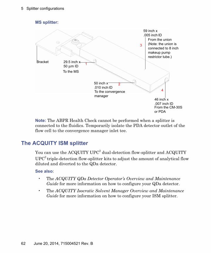
MS splitter:
29.5 inch x 50 μm ID
26.0 inch x .007 inch ID
50.0 inch x .010 inch ID
To the convergence manager
To the ELSD
From the column manager or PDA
Bracket1
2 3
29.5 inch x 50 μm ID
50 inch x .010 inch ID
59 inch x .005 inch ID
26 inch x .007 inch ID
To the MS
To the convergence manager
From the union(Note: the union is connected to 8 inch makeup pump restrictor tube.)
From the column manager or PDA
1
2
3
4
Bracket
60 June 20, 2014, 715004521 Rev. B

ACQUITY UPC2 splitter hardware components
Note: The ABPR Health Check cannot be performed when a splitter is connected to the fluidics. Temporarily isolate the PDA detector outlet of the flow cell to the convergence manager inlet tee.
Core 4 configuration splitter hardware components
ELSD splitter:
29.5 inch x 50 μm ID
46.0 inch x .007 inch ID
50.0 inch x .010 inch ID
To the convergence manager
To the ELSD
From the CM-30S or PDA
Bracket1
2 3
June 20, 2014, 715004521 Rev. B 61
5 Splitter configurations
MS splitter:
Note: The ABPR Health Check cannot be performed when a splitter is connected to the fluidics. Temporarily isolate the PDA detector outlet of the flow cell to the convergence manager inlet tee.
The ACQUITY ISM splitter
You can use the ACQUITY UPC2 dual-detection flow-splitter and ACQUITY UPC2 triple-detection flow-splitter kits to adjust the amount of analytical flow diluted and diverted to the QDa detector.
See also:
• The ACQUITY QDa Detector Operator’s Overview and Maintenance Guide for more information on how to configure your QDa detector.
• The ACQUITY Isocratic Solvent Manager Overview and Maintenance Guide for more information on how to configure your ISM splitter.
29.5 inch x 50 μm ID
50 inch x .010 inch ID
59 inch x .005 inch ID
46 inch x .007 inch ID
To the MS
To the convergence manager
From the union(Note: the union is connected to 8 inch makeup pump restrictor tube.)
From the CM-30S or PDA
1
2
3
4
Bracket
62 June 20, 2014, 715004521 Rev. B

ACQUITY UPC2 splitter hardware components
ISM splitter module for dual detection:
ISM splitter module for triple detection:
From the PDATo the convergence manager
QDa detector probe
0.010 inch ID PEEK 0.007 inch ID PEEK
12
From the PDA
To the convergence manager0.010 inch ID PEEK
0.007 inch ID PEEK To the
ELSD75 µm ID PEEKSIL
QDa detector probe
1
3 2
June 20, 2014, 715004521 Rev. B 63
5 Splitter configurations
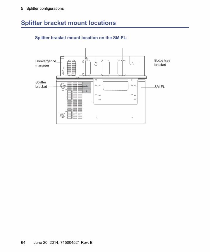
Splitter bracket mount locations
Splitter bracket mount location on the SM-FL:
TP03510
Convergence manager
SM-FL
Bottle tray bracket
Splitter bracket
64 June 20, 2014, 715004521 Rev. B

Splitter bracket mount locations
Splitter bracket mount location on the CM-A:
Splitter bracket mount location on the CM-Aux:
TP03511
Convergence manager
Bottle tray bracket
Splitter bracketColumn
manager
TP03508
Splitter bracket
CM-Aux
June 20, 2014, 715004521 Rev. B 65

5 Splitter configurations
Splitter bracket mount location on the CM-30S:
Splitter bracket mount location on the PDA:
Splitter bracket
CM-30S
TP03507
PDA
Splitter bracket
66 June 20, 2014, 715004521 Rev. B

Splitter bracket mount locations
Splitter bracket mount location on the 515 makeup pump:
515 makeup pump
Splitter bracket
June 20, 2014, 715004521 Rev. B 67

5 Splitter configurations
Core 1 configuration: system diagrams and tubing connections
Core 1 configuration with a PDA, ELSD, and splitter:
TP03523
ELSD
Convergence manager
Solvent tray
ELSD splitter mounted to the SM-FL
PDA
SM-FL CM-AccBSM
1
2
3
68 June 20, 2014, 715004521 Rev. B

Core 1 configuration: system diagrams and tubing connections
The following table describes final tubing connections and does not list factory-installed tubing connections.
Core 1configuration with a PDA, ELSD, and splitter:
TubeTube description
From To ID inches
Notes:recommendedtrim length
1 29.5 inch PEEK-sil tubing
Splitter module
ELSD 50 μm Do not trim
2 26 inchPEEK tubing(pre-connected to the splitter)
CM-A or PDA
Splitter module
0.007 Do not trim more than 3 inches
3 50 inch PEEK tubing(pre-connected to the splitter)
Splitter module
Left side of the convergence manager tee
0.010 Do not trim more than 20 inches
June 20, 2014, 715004521 Rev. B 69

5 Splitter configurations
Core 1 configuration with a PDA, SQD, and splitter:
TP03524
PDA
CM-A
MS splitter mounted to CM-A
Solvent traySQD
515 makeup pumpConvergence manager
SM-FL
ccBSM
Pump control module
1
2
3
4
70 June 20, 2014, 715004521 Rev. B

Core 1 configuration: system diagrams and tubing connections
The following table describes final tubing connections and does not list factory-installed tubing connections.
Core 1 configuration with a PDA, SQD, and splitter:
TubeTube description
From To ID inches
Notes:recommendedtrim length
1 29.5 inch PEEK-sil tubing (pre-connected to the splitter)
Splitter module
SQD probe 50 μm Do not trim
2 50 inch PEEK tubing(pre-connected to the splitter)
Splitter module
Left side of the convergence manager tee
0.010 Do not trim more than 23 inches
3 59 inchPEEK tubing (pre-connected to the splitter)
Top of the PEEK union on the 515 makeup pump
Splitter module
0.005 Trim as required
4 26 inch PEEK tubing(pre-connected to the splitter)
CM-A or PDA
Splitter module
0.007 Do not trim
June 20, 2014, 715004521 Rev. B 71

5 Splitter configurations
Core 1 configuration with a PDA, ISM, and QDa:
������
Solvent tray
Convergence manager
ccBSM
CM-A
PDA
ISM with UPC2
splitter
QDa
SM-FL
2
1
3
ISM splitter module
72 June 20, 2014, 715004521 Rev. B

Core 1 configuration: system diagrams and tubing connections
The following table describes final tubing connections and does not list factory-installed tubing connections.
Core 1 configuration with a PDA, ISM, and QDa:
TubeTube description
From To ID inches
Notes:recommendedtrim length
1 60.0 inch PEEK tubing
ISM splitter module
Convergence manager vent valve tee
0.007 Optional trim up to 30 inches
2 28.0 inch PEEK tubing
CM-A or PDA ISM splitter module
0.007 Trim to 15 inches
3 Probe ISM splitter module
QDa probe N/A N/A
June 20, 2014, 715004521 Rev. B 73

5 Splitter configurations
Core 1 configuration with a PDA, ELSD, ISM, and QDa:
�����
Solvent tray
Convergence manager
ccBSM
CM-A
PDA
ISM with UPC2 splitter
QDa
SM-FL
ELSD
4
21
3
ISM splitter module
74 June 20, 2014, 715004521 Rev. B
Core 1 configuration: system diagrams and tubing connections
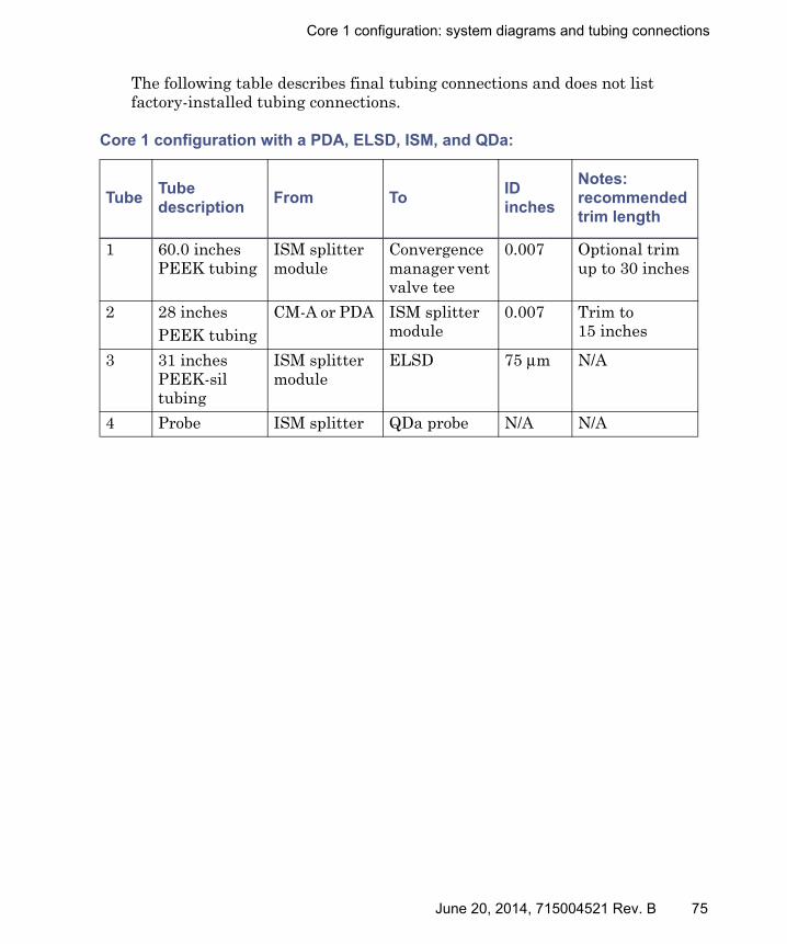
The following table describes final tubing connections and does not list factory-installed tubing connections.
Core 1 configuration with a PDA, ELSD, ISM, and QDa:
TubeTube description
From To ID inches
Notes:recommendedtrim length
1 60.0 inches PEEK tubing
ISM splitter module
Convergence manager vent valve tee
0.007 Optional trim up to 30 inches
2 28 inchesPEEK tubing
CM-A or PDA ISM splitter module
0.007 Trim to 15 inches
3 31 inchesPEEK-sil tubing
ISM splitter module
ELSD 75 μm N/A
4 Probe ISM splitter QDa probe N/A N/A
June 20, 2014, 715004521 Rev. B 75
5 Splitter configurations
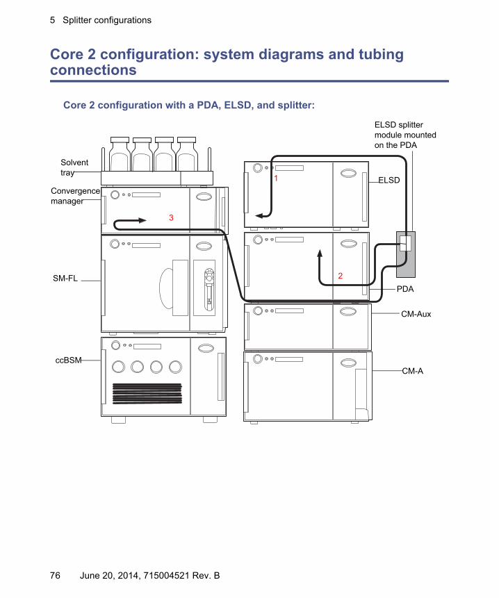
Core 2 configuration: system diagrams and tubing connections
Core 2 configuration with a PDA, ELSD, and splitter:
TP03524
SM-FL
ccBSM
Solvent tray
ELSD
PDA
CM-Aux
CM-A
ELSD splitter module mounted on the PDA
Convergence manager
2
1
3
76 June 20, 2014, 715004521 Rev. B

Core 2 configuration: system diagrams and tubing connections
The following table describes final tubing connections and does not list factory-installed tubing connections.
Core 2 configuration with a PDA, ELSD, and splitter:
TubeTube description
From To ID inches
Notes:recommendedtrim length
1 29.5 inch PEEK-sil tubing (pre-connected to the splitter)
Splitter module
ELSD 50 μm Do not trim
2 26 inch PEEK tubing(pre-connected to the splitter)
CM-A or PDA
Splitter module
0.007 Do not trim more than 10 inches
3 50 inchPEEK tubing(pre-connected to the splitter)
Splitter module
Left side of the convergence manager tee
0.010 Do not trim more than 6 inches
June 20, 2014, 715004521 Rev. B 77

5 Splitter configurations
Core 2 configuration with a PDA, SQD, and splitter:
TP03526
SQD
MS splitter module mounted to 515 makeup pump
PEEK union
Check valve515 makeup pump
CM-Aux
CM-A
PDA
Solvent tray Convergence manager
SM-FL ccBSM
4
2
1
3
78 June 20, 2014, 715004521 Rev. B

Core 2 configuration: system diagrams and tubing connections
The following table describes final tubing connections and does not list factory-installed tubing connections.
Core 2 configuration with a PDA, SQD, and splitter:
TubeTube description
From To ID inches
Notes:recommendedtrim length
1 29.5 inch PEEK-sil tubing (pre-connected to the splitter)
Splitter module
MS 50 μm Do not trim
2 50 inchPEEK tubing(pre-connected to the splitter)
Splitter module
Left side of the convergence manager tee
0.010 Do not trim more than 23 inches
3 59 inchPEEK tubing (pre-connected to the splitter)
Top of the PEEK union on the 515 makeup pump
Splitter module
0.005 Trim as required
4 26 inchPEEK tubing(pre-connected to the splitter)
The CM-A or PDA
Splitter module
0.007 Do not trim
June 20, 2014, 715004521 Rev. B 79

5 Splitter configurations
Core 3 configuration: system diagrams and tubing connections
Core 3 configuration with a PDA, ELSD, and splitter:
TP03530
ELSD
PDA
CM-Aux
CM-A
CM-Aux
ELSD splitter module mounted onthe PDA
Solvent tray
Convergence manager
SM-FL
ccBSM
2
1
3
80 June 20, 2014, 715004521 Rev. B

Core 3 configuration: system diagrams and tubing connections
The following table describes final tubing connections and does not list factory-installed tubing connections.
Core 3 configuration with a PDA, ELSD, and splitter:
TubeTube description
From To ID inches
Notes:recommendedtrim length
1 29.5 inch PEEK-sil tubing (pre-connected to the splitter)
Splitter module
ELSD 50 μm Do not trim
2 26 inch PEEK tubing(pre-connected to the splitter)
CM-A or PDA
Splitter module
0.007 Do not trim more than 10 inches
3 50 inch PEEK tubing(pre-connected to the splitter)
Splitter module
Left side of the convergence manager tee
0.010 Do not trim more than 8 inches
June 20, 2014, 715004521 Rev. B 81

5 Splitter configurations
Core 3 configuration with a PDA, SQD, and splitter:
TP03531
CM-Aux
CM-A
CM-Aux
PDA
Convergence manager
Solvent tray
SQD
515 makeup pump
MS splitter module mounted to 515 makeup pump
PEEK union
Check valve
SM-FL ccBSM
42
1
3
82 June 20, 2014, 715004521 Rev. B

Core 3 configuration: system diagrams and tubing connections
The following table describes final tubing connections and does not list factory-installed tubing connections.
Core 3 configuration with a PDA, SQD, and splitter:
TubeTube description
From To ID inches
Notes:recommendedtrim length
1 29.5PEEK-sil tubing (pre-connected to the splitter)
Splitter module
MS 50 μm Do not trim
2 50 inch PEEK tubing(pre-connected to the splitter)
Splitter module
Left side of the convergence manager tee
0.010 Do not trim more that 8 inches
3 59 inch PEEK tubing (pre-connected to the splitter)
Top of the PEEK union on the 515 makeup pump
Splitter module
0.005 Trim as needed
4 26 inchPEEK tubing(pre-connected to the splitter)
CM-A or PDA
Splitter module
0.007 Do not trim more that 8 inches
June 20, 2014, 715004521 Rev. B 83

5 Splitter configurations
Core 3 configuration with a PDA, ISM, and QDa:
������
Solvent tray
PDA
Convergence manager
SM-FL
ccBSM
CM-AUX
CM-A
CM-AUX
ISM with UPC2 splitter module
QDaISM splitter module
2
1
3
84 June 20, 2014, 715004521 Rev. B

Core 3 configuration: system diagrams and tubing connections
The following table describes final tubing connections and does not list factory-installed tubing connections.
Core 3 configuration with a PDA, ISM, and QDa:
TubeTube description
From To ID inches
Notes:recommendedtrim length
1 60.0 inch PEEK tubing
ISM splitter module
Convergence manager vent valve tee
0.007 Optional trim up to 30 inches
2 28.0 inch PEEK tubing
CM-A or PDA ISM splitter module
0.007 Trim to 15 inches
3 Probe ISM splitter module
QDa probe N/A N/A
June 20, 2014, 715004521 Rev. B 85
5 Splitter configurations
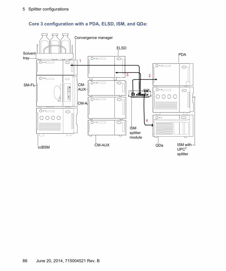
Core 3 configuration with a PDA, ELSD, ISM, and QDa:
������
Solvent tray
Convergence manager
SM-FL
ccBSM
ELSD
CM-AUX
CM-A
CM-AUX
PDA
ISM with UPC2 splitter
QDa
4
2
1
3
ISM splitter module
86 June 20, 2014, 715004521 Rev. B
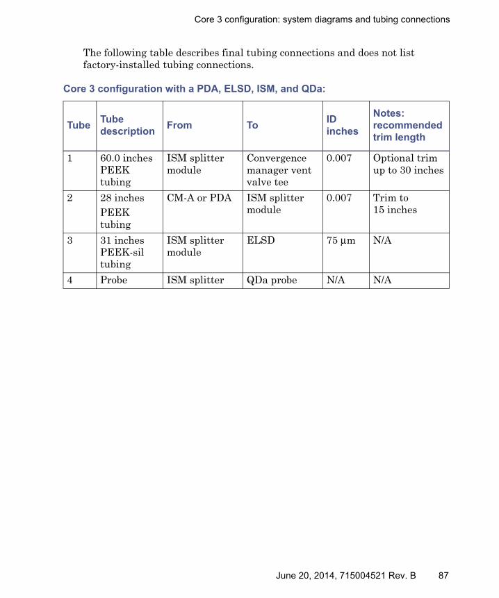
Core 3 configuration: system diagrams and tubing connections
The following table describes final tubing connections and does not list factory-installed tubing connections.
Core 3 configuration with a PDA, ELSD, ISM, and QDa:
TubeTube description
From To ID inches
Notes:recommendedtrim length
1 60.0 inches PEEK tubing
ISM splitter module
Convergence manager vent valve tee
0.007 Optional trim up to 30 inches
2 28 inchesPEEK tubing
CM-A or PDA ISM splitter module
0.007 Trim to 15 inches
3 31 inchesPEEK-sil tubing
ISM splitter module
ELSD 75 μm N/A
4 Probe ISM splitter QDa probe N/A N/A
June 20, 2014, 715004521 Rev. B 87

5 Splitter configurations
Core 4 configuration: system diagrams and tubing connections
CM-30S column configuration
88 June 20, 2014, 715004521 Rev. B

Core 4 configuration: system diagrams and tubing connections
Core 4 configuration with a PDA, ELSD, and splitter:
������
Solvent tray
ELSDCM-30S
PDA
ccBSMSM-FL
Convergence manager
ELSD splitter module mounted on the CM-30S
2
1
3
June 20, 2014, 715004521 Rev. B 89

5 Splitter configurations
The following table describes final tubing connections and does not list factory-installed tubing connections.
Core 4 configuration with a PDA, ELSD, and splitter:
TubeTube description
From To ID inches
Notes:recommendedtrim length
1 29.5 inch PEEK-sil(pre-connected to the splitter)
Splitter module
ELSD 50 μm Do not trim
2 46 inch(pre-connected to the splitter)
CM-30S or PDA
Splitter module
0.007 Do not trim more than 3 inches
3 50 inch(pre-connected to the splitter)
Splitter module
Convergence manager
0.007 Do not trim more than 20 inches
90 June 20, 2014, 715004521 Rev. B
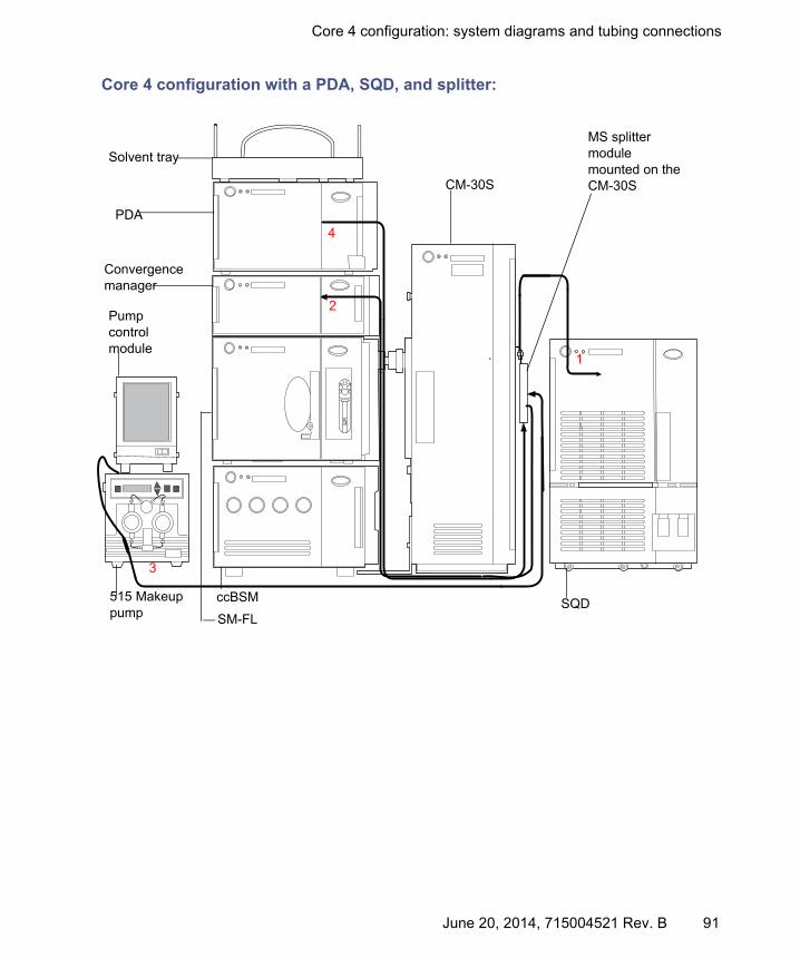
Core 4 configuration: system diagrams and tubing connections
Core 4 configuration with a PDA, SQD, and splitter:
�������
Pump control module
515 Makeup pump
Solvent tray
PDA
Convergence manager
CM-30S
SM-FL
ccBSM SQD
MS splitter module mounted on the CM-30S
4
2
1
3
June 20, 2014, 715004521 Rev. B 91
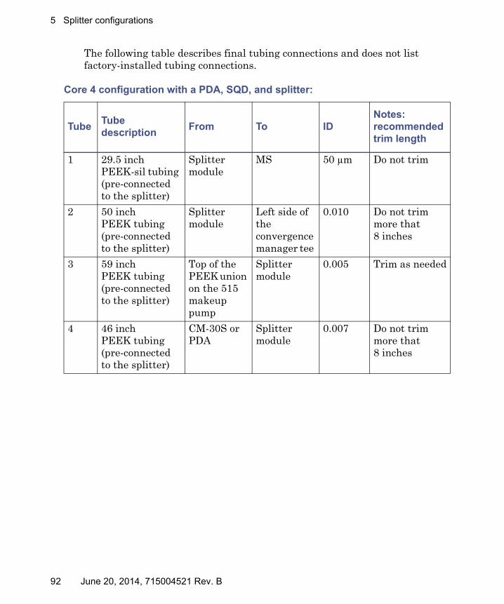
5 Splitter configurations
The following table describes final tubing connections and does not list factory-installed tubing connections.
Core 4 configuration with a PDA, SQD, and splitter:
TubeTube description
From To ID Notes:recommendedtrim length
1 29.5 inchPEEK-sil tubing (pre-connected to the splitter)
Splitter module
MS 50 μm Do not trim
2 50 inch PEEK tubing(pre-connected to the splitter)
Splitter module
Left side of the convergence manager tee
0.010 Do not trim more that 8 inches
3 59 inch PEEK tubing (pre-connected to the splitter)
Top of the PEEK union on the 515 makeup pump
Splitter module
0.005 Trim as needed
4 46 inchPEEK tubing(pre-connected to the splitter)
CM-30S or PDA
Splitter module
0.007 Do not trim more that 8 inches
92 June 20, 2014, 715004521 Rev. B

Core 4 configuration: system diagrams and tubing connections
Core 4 configuration with a PDA, ISM, and QDa:
Solvent trayConvergence manager
SM-FL
ccBSM CM-30S QDa
ISM with UPC2 splitterPDA
1
2
3
June 20, 2014, 715004521 Rev. B 93
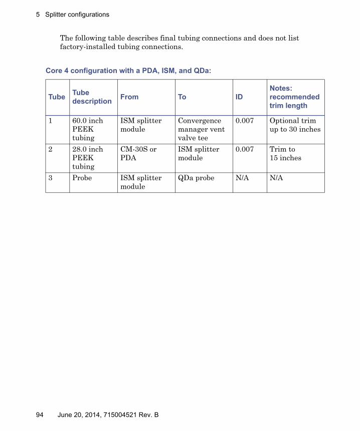
5 Splitter configurations
The following table describes final tubing connections and does not list factory-installed tubing connections.
Core 4 configuration with a PDA, ISM, and QDa:
TubeTube description
From To ID Notes:recommendedtrim length
1 60.0 inch PEEK tubing
ISM splitter module
Convergence manager vent valve tee
0.007 Optional trim up to 30 inches
2 28.0 inch PEEK tubing
CM-30S or PDA
ISM splitter module
0.007 Trim to 15 inches
3 Probe ISM splitter module
QDa probe N/A N/A
94 June 20, 2014, 715004521 Rev. B
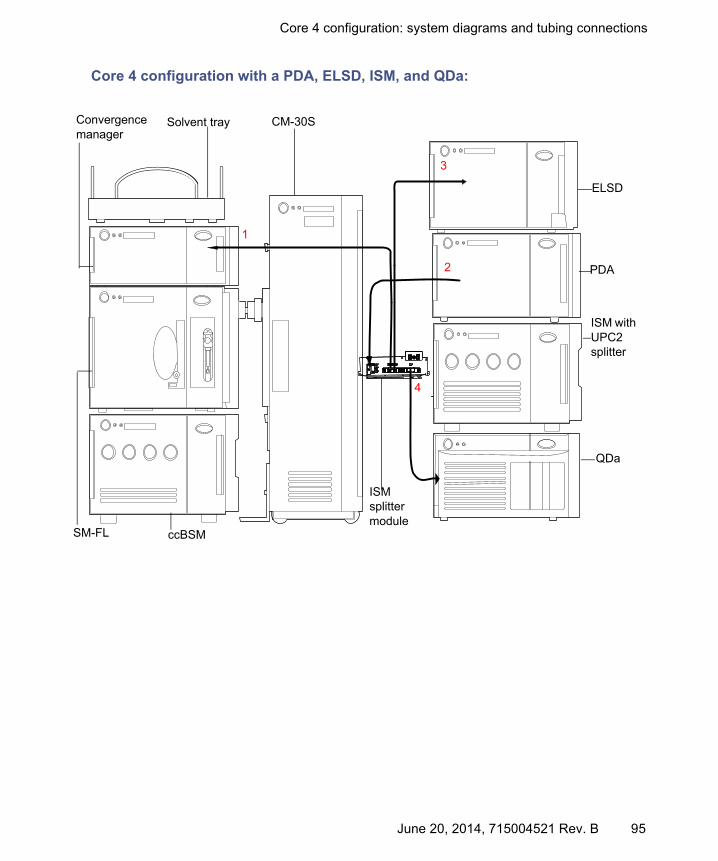
Core 4 configuration: system diagrams and tubing connections
Core 4 configuration with a PDA, ELSD, ISM, and QDa:
Solvent tray
ELSD
PDA
ISM with UPC2 splitter
QDa
CM-30SConvergence manager
SM-FL ccBSM
4
2
1
3
ISM splitter module
June 20, 2014, 715004521 Rev. B 95

5 Splitter configurations
The following table describes final tubing connections and does not list factory-installed tubing connections.
Core 4 configuration with a PDA, ELSD, ISM, and QDa:
TubeTube description
From To ID Notes:recommendedtrim length
1 60.0 inch PEEK tubing
ISM splitter module
Convergence manager vent valve tee
0.007 Optional trim up to 30 inches
2 28 inchPEEK tubing
CM-30S or PDA
ISM splitter module
0.007 Trim to 15 inches
3 31 inchPEEK-sil tubing
ISM splitter module
ELSD 75 μm N/A
4 Probe ISM splitter QDa probe N/A N/A
96 June 20, 2014, 715004521 Rev. B

Maintaining the ACQUITY UPC2 system modules
6 Maintaining the ACQUITY UPC2 system
This chapter provides the maintenance guidelines and procedures necessary to maintain the instrument’s performance.
Follow a maintenance schedule, and perform maintenance as required and described in this chapter.
Maintaining the ACQUITY UPC2 system modules
Consult the following documentation on the ACQUITY UPC2 documentation CD for details on maintaining the ACQUITY UPC2 system modules:
• ACQUITY UPC2 Binary Solvent Manager Operator’s Overview and Maintenance Guide
• ACQUITY UPLC Column Compartments Operator's Overview and Maintenance Guide
• ACQUITY 30-cm Single-Zone Column Manager Overview and Maintenance Guide
• ACQUITY UPC2 Convergence Manager Operator’s Overview and Maintenance Guide
Contents:
Topic Page
Maintaining the ACQUITY UPC2 system modules....................... 97
Maintaining the automated backpressure regulator ..................... 98
Spare parts ....................................................................................... 100
Troubleshooting with Connections INSIGHT ................................ 100
Safety and handling......................................................................... 102
June 20, 2014, 715004521 Rev. B 97

6 Maintaining the ACQUITY UPC2 system
• ACQUITY UPC2 Photodiode Array Detector Overview and Maintenance Guide
• ACQUITY UPC2 Sample Manager - Fixed Loop Operator’s Overview and Maintenance Guide
Maintaining the automated backpressure regulator
The convergence manager’s automated back pressure regulator (ABPR) contains mechanisms that control system pressure while the system is running. The preheated ABPR prevents freezing when the CO2 undergoes a phase change.
See also: The console online Help for more information about the ABPR health test.
Note: The ABPR health test cannot be performed when an ELSD or MS splitter is connected. Temporarily isolate the PDA detector outlet of the flow cell to the convergence manager inlet tee.
Running an ABPR health test when the system includes a 30-cm single-zone column manager
The ABPR health test ensures the UPC2 convergence manager’s ABPR is functioning properly. Run the ABPR health test before starting the system and after performing maintenance on the convergence manager.
Instructions for performing the ABPR health test are provided in the console online Help. However, if your system has a 30-cm single-zone column manager, you must also do the following before running an ABPR test:
• Set the operation mode to enable bypass.
• Temporarily install a union in place of the column in position 8.
Tips:
• If your system has 2, 30-cm single-zone column managers, repeat these steps for the second column manager.
• Both column managers must be configured to contain a bypass in order for the ABPR test to run.
98 June 20, 2014, 715004521 Rev. B

Maintaining the automated backpressure regulator
To set the operation mode to enable bypass:
1. From the console system tree, select the column manager.
2. From the Configure menu, select Operating mode.
3. In the Operating Mode Configuration dialog box, under “Select mode of operation”, select “Column Selection”.
4. Select “Bypass”.
To run a ABPR test in a system that includes a 30-cm single-zone column manager:
1. Pull out the drawer to the column manager to access the columns.
2. Remove the column in position 8 by unscrewing the outlet (bottom) and then the inlet (top).
Removing the position 8 column:
3. Screw the union to the inlet.
Position 8 is on the right-hand side in the back.
June 20, 2014, 715004521 Rev. B 99
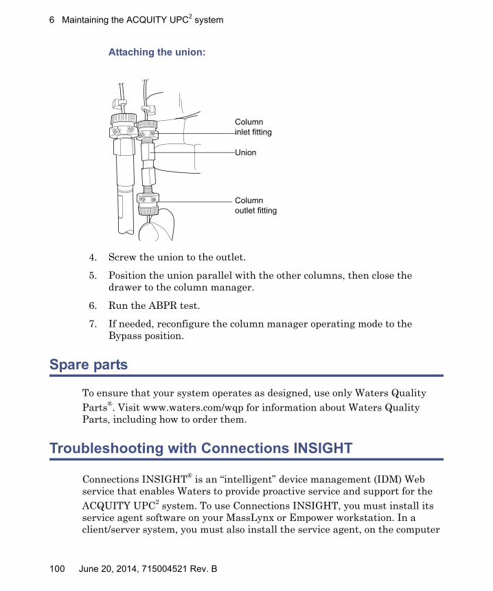
6 Maintaining the ACQUITY UPC2 system
Attaching the union:
4. Screw the union to the outlet.
5. Position the union parallel with the other columns, then close the drawer to the column manager.
6. Run the ABPR test.
7. If needed, reconfigure the column manager operating mode to the Bypass position.
Spare parts
To ensure that your system operates as designed, use only Waters Quality Parts®. Visit www.waters.com/wqp for information about Waters Quality Parts, including how to order them.
Troubleshooting with Connections INSIGHT
Connections INSIGHT® is an “intelligent” device management (IDM) Web service that enables Waters to provide proactive service and support for the ACQUITY UPC2 system. To use Connections INSIGHT, you must install its service agent software on your MassLynx or Empower workstation. In a client/server system, you must also install the service agent, on the computer
Union
Column inlet fitting
Column outlet fitting
100 June 20, 2014, 715004521 Rev. B

Troubleshooting with Connections INSIGHT
from which you control the system. The service agent software automatically and securely captures and sends information about the support needs of your system directly to Waters.
If you encounter a performance issue when using the Instrument Console, you can manually submit a Connections Insight request to Waters customer support. Alternatively, you can use Remote Desktop, a real-time collaboration option that controls the two-way connection with the ACQUITY UPC2 system by enabling the Connections INSIGHT iAssist service level.
Consult these sources for more information about Connections INSIGHT and Connections INSIGHT iAssist:
• http://www.waters.com
• Connections INSIGHT Installation Guide (part number 715001399)
• Connections INSIGHT User's Guide (part number 715001400)
• Your sales representative
• Your local Waters subsidiary
• Waters Customer Support
To submit a Connections Insight request:
1. Select Troubleshoot > Submit Connections Insight request.
2. In the Connections Insight Request dialog box, type your name, telephone number, e-mail address, and a description of the problem.
3. Click Submit, and allow approximately 5 minutes to save the service profile.
Result: A .zip file containing your Connections Insight profile is forwarded to Waters customer support for review.
Tip: Saving a service profile or plot file from the Instrument Console can require as much as 150 MB of file space.
June 20, 2014, 715004521 Rev. B 101
6 Maintaining the ACQUITY UPC2 system
Safety and handling
Bear in mind the following safety considerations when performing maintenance procedures:
See Appendix A for safety advisory information.
Warning: The instrument components can be contaminated with biologically hazardous materials. Always wear chemical-resistant, powder-free gloves while handling the components.
Warning: To prevent injury, always observe Good Laboratory Practice when handling solvents, changing tubing, or operating the instrument. Know the physical and chemical properties of the solvents used (see the Material Safety Data Sheets for the solvents in use).
Warning: To avoid electric shock,• do not remove the instrument’s panels. There are no user-serviceable
items inside the instrument.• ensure that the instrument is in Standby mode before commencing
any maintenance.
Warning: The probe and source can be hot. To avoid burn injuries, take great care while working with these components.
Notice: When performing maintenance inside the source enclosure, ensure that the following criteria are met:• Instrument is in Standby mode.• LC flow is diverted to waste or set to off.• Desolvation gas is turned off.
102 June 20, 2014, 715004521 Rev. B

Warning symbols
A Safety advisories
Waters instruments and devices display hazard symbols that alert you to the hidden dangers associated with a product’s operation and maintenance. The symbols also appear in product manuals where they accompany statements describing the hazards and advising how to avoid them. This appendix presents the safety symbols and statements that apply to all of the products that Waters offers.
Warning symbols
Warning symbols alert you to the risk of death, injury or seriously adverse physiological reactions associated with an instrument’s use or misuse. Heed all warnings when you install, repair, or operate any Waters instrument or device. Waters accepts no liability in cases of injury or property damage resulting from the failure of individuals to comply with any safety precaution when installing, repairing, or operating any of its instruments or devices.
The following symbols warn of risks that can arise when you operate or maintain a Waters instrument or device, or a component of an instrument or device. When one of these symbols appear in a manual’s narrative sections or
Contents:
Topic Page
Warning symbols.............................................................................. 103
Notices .............................................................................................. 106
Warnings that apply to all Waters instruments and devices ........ 107
Warnings that address the replacing of fuses ................................ 112
Electrical and handling symbols ..................................................... 114
June 20, 2014, 715004521 Rev. B 103

A Safety advisories
procedures, an accompanying statement identifies the applicable risk and explains how to avoid it.
The following warnings (both symbols and text) can appear in the user manuals of particular instruments and devices and on labels affixed to them or their component parts.
Warning: (General risk of danger. When this symbol appears on an instrument, consult the instrument’s user documentation for important safety-related information before you use the instrument.)
Warning: (Risk of burn injury from contacting hot surfaces.)
Warning: (Risk of electric shock.)
Warning: (Risk of fire.)
Warning: (Risk of sharp-point puncture injury.)
Warning: (Risk of hand crush injury.)
Warning: (Risk of injury caused by moving machinery.)
Warning: (Risk of exposure to ultraviolet radiation.)
Warning: (Risk of contacting corrosive substances.)
Warning: (Risk of exposure to a toxic substance.)
Warning: (Risk of personal exposure to laser radiation.)
Warning: (Risk of exposure to biological agents that can pose a serious health threat.)
Warning: (Risk of tipping.)
Warning: (Risk of explosion.)
Warning: (Risk of eye injury.)
104 June 20, 2014, 715004521 Rev. B

Warning symbols
Burst warning
This warning applies to Waters instruments and devices fitted with nonmetallic tubing.
Biohazard warning
The following warning applies to Waters instruments and devices that can process material containing biohazards, which are substances that contain biological agents capable of producing harmful effects in humans.
Warning: To avoid injury from bursting, nonmetallic tubing, heed these precautions when working in the vicinity of such tubing when it is pressurized:• Wear eye protection.• Extinguish all nearby flames.• Do not use tubing that is, or has been, stressed or kinked.• Do not expose nonmetallic tubing to incompatible compounds like
tetrahydrofuran (THF) and nitric or sulfuric acids.• Be aware that some compounds, like methylene chloride and
dimethyl sulfoxide, can cause nonmetallic tubing to swell, significantly reducing the pressure at which the tubing can rupture.
Warning: To avoid infection with potentially infectious, human-sourced products, inactivated microorganisms, and other biological materials, assume that all biological fluids that you handle are infectious. Specific precautions appear in the latest edition of the US National Institutes of Health (NIH) publication, Biosafety in Microbiological and Biomedical Laboratories (BMBL).Observe Good Laboratory Practice (GLP) at all times, particularly when working with hazardous materials, and consult the biohazard safety representative for your organization regarding the proper use and handling of infectious substances.
June 20, 2014, 715004521 Rev. B 105

A Safety advisories
Biohazard and chemical hazard warning
This warning applies to Waters instruments and devices that can process biohazards, corrosive materials, or toxic materials.
Notices
Notices appear where an instrument or device can be subject to use or misuse that can damage it or compromise a sample’s integrity. The exclamation point symbol and its associated statement alert you to such risk.
Warning: To avoid personal contamination with biohazards, toxic materials, or corrosive materials, you must understand the hazards associated with their handling. Guidelines prescribing the proper use and handling of such materials appear in the latest edition of the National Research Council's publication, Prudent Practices in the Laboratory: Handling and Disposal of Chemicals. Observe Good Laboratory Practice (GLP) at all times, particularly when working with hazardous materials, and consult the safety representative for your organization regarding its protocols for handling such materials.
Notice: To avoid damaging the instrument’s case, do not clean it with abrasives or solvents.
106 June 20, 2014, 715004521 Rev. B

Warnings that apply to all Waters instruments and devices
Warnings that apply to all Waters instruments and devices
When operating this device, follow standard quality-control procedures and the equipment guidelines in this section.
Attention: Changes or modifications to this unit not expressly approved by the party responsible for compliance could void the user’s authority to operate the equipment.
Important: Toute modification sur cette unité n’ayant pas été expressément approuvée par l’autorité responsable de la conformité à la réglementation peut annuler le droit de l’utilisateur à exploiter l’équipement.
Achtung: Jedwede Änderungen oder Modifikationen an dem Gerät ohne die ausdrückliche Genehmigung der für die ordnungsgemäße Funktionstüchtigkeit verantwortlichen Personen kann zum Entzug der Bedienungsbefugnis des Systems führen.
Avvertenza: qualsiasi modifica o alterazione apportata a questa unità e non espressamente autorizzata dai responsabili per la conformità fa decadere il diritto all'utilizzo dell'apparecchiatura da parte dell'utente.
Atencion: cualquier cambio o modificación efectuado en esta unidad que no haya sido expresamente aprobado por la parte responsable del cumplimiento puede anular la autorización del usuario para utilizar el equipo.
注意:未經有關法規認證部門允許對本設備進行的改變或修改,可能會使使用者喪失操作該設
備的權利。
注意:未经有关法规认证部门明确允许对本设备进行的改变或改装,可能会使使用者丧失操作该设备的合法性。
주의: 규정 준수를 책임지는 당사자의 명백한 승인 없이 이 장치를 개조 또는 변경할 경우, 이 장치를 운용할 수 있는 사용자 권한의 효력을 상실할 수 있습니다.
注意:規制機関から明確な承認を受けずに本装置の変更や改造を行うと、本装置のユーザーとしての承認が無効になる可能性があります。
June 20, 2014, 715004521 Rev. B 107

A Safety advisories
Warning: Use caution when working with any polymer tubing under pressure:• Always wear eye protection when near pressurized polymer tubing.• Extinguish all nearby flames.• Do not use tubing that has been severely stressed or kinked.• Do not use nonmetallic tubing with tetrahydrofuran (THF) or concentrated
nitric or sulfuric acids.• Be aware that methylene chloride and dimethyl sulfoxide cause nonmetallic
tubing to swell, which greatly reduces the rupture pressure of the tubing.Attention: Manipulez les tubes en polymère sous pression avec precaution:• Portez systématiquement des lunettes de protection lorsque vous vous
trouvez à proximité de tubes en polymère pressurisés.• Eteignez toute flamme se trouvant à proximité de l’instrument.• Evitez d'utiliser des tubes sévèrement déformés ou endommagés.• Evitez d'utiliser des tubes non métalliques avec du tétrahydrofurane (THF)
ou de l'acide sulfurique ou nitrique concentré.• Sachez que le chlorure de méthylène et le diméthylesulfoxyde entraînent le
gonflement des tuyaux non métalliques, ce qui réduit considérablement leur pression de rupture.
Vorsicht: Bei der Arbeit mit Polymerschläuchen unter Druck ist besondere Vorsicht angebracht:• In der Nähe von unter Druck stehenden Polymerschläuchen stets
Schutzbrille tragen.• Alle offenen Flammen in der Nähe löschen.• Keine Schläuche verwenden, die stark geknickt oder überbeansprucht sind.• Nichtmetallische Schläuche nicht für Tetrahydrofuran (THF) oder
konzentrierte Salpeter- oder Schwefelsäure verwenden.• Durch Methylenchlorid und Dimethylsulfoxid können nichtmetallische
Schläuche quellen; dadurch wird der Berstdruck des Schlauches erheblich reduziert.
108 June 20, 2014, 715004521 Rev. B
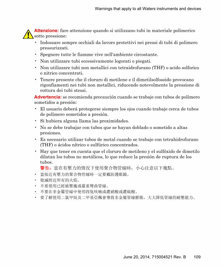
Warnings that apply to all Waters instruments and devices
Attenzione: fare attenzione quando si utilizzano tubi in materiale polimerico sotto pressione:• Indossare sempre occhiali da lavoro protettivi nei pressi di tubi di polimero
pressurizzati.• Spegnere tutte le fiamme vive nell'ambiente circostante.• Non utilizzare tubi eccessivamente logorati o piegati.• Non utilizzare tubi non metallici con tetraidrofurano (THF) o acido solforico
o nitrico concentrati.• Tenere presente che il cloruro di metilene e il dimetilsolfossido provocano
rigonfiamenti nei tubi non metallici, riducendo notevolmente la pressione di rottura dei tubi stessi.
Advertencia: se recomienda precaución cuando se trabaje con tubos de polímero sometidos a presión:• El usuario deberá protegerse siempre los ojos cuando trabaje cerca de tubos
de polímero sometidos a presión.• Si hubiera alguna llama las proximidades.• No se debe trabajar con tubos que se hayan doblado o sometido a altas
presiones.• Es necesario utilizar tubos de metal cuando se trabaje con tetrahidrofurano
(THF) o ácidos nítrico o sulfúrico concentrados.• Hay que tener en cuenta que el cloruro de metileno y el sulfóxido de dimetilo
dilatan los tubos no metálicos, lo que reduce la presión de ruptura de los tubos.警告:當在有壓力的情況下使用聚合物管線時,小心注意以下幾點。
• 當接近有壓力的聚合物管線時一定要戴防護眼鏡。
• 熄滅附近所有的火焰。
• 不要使用已經被壓癟或嚴重彎曲管線。
• 不要在非金屬管線中使用四氫呋喃或濃硝酸或濃硫酸。
• 要了解使用二氯甲烷及二甲基亞楓會導致非金屬管線膨脹,大大降低管線的耐壓能力。
June 20, 2014, 715004521 Rev. B 109
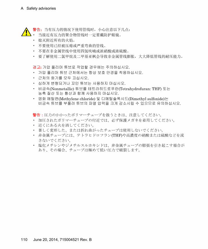
A Safety advisories
警告:当有压力的情况下使用管线时,小心注意以下几点:
• 当接近有压力的聚合物管线时一定要戴防护眼镜。
• 熄灭附近所有的火焰。
• 不要使用已经被压瘪或严重弯曲的管线。
• 不要在非金属管线中使用四氢呋喃或浓硝酸或浓硫酸。
• 要了解使用二氯甲烷及二甲基亚枫会导致非金属管线膨胀,大大降低管线的耐压能力。
경고: 가압 폴리머 튜브로 작업할 경우에는 주의하십시오.• 가압 폴리머 튜브 근처에서는 항상 보호 안경을 착용하십시오.• 근처의 화기를 모두 끄십시오.• 심하게 변형되거나 꼬인 튜브는 사용하지 마십시오.• 비금속(Nonmetallic) 튜브를 테트라히드로푸란(Tetrahydrofuran: THF) 또는 농축 질산 또는 황산과 함께 사용하지 마십시오.
• 염화 메틸렌(Methylene chloride) 및 디메틸술폭시드(Dimethyl sulfoxide)는 비금속 튜브를 부풀려 튜브의 파열 압력을 크게 감소시킬 수 있으므로 유의하십시오.
警告:圧力のかかったポリマーチューブを扱うときは、注意してください。
• 加圧されたポリマーチューブの付近では、必ず保護メガネを着用してください。
• 近くにある火を消してください。
• 著しく変形した、または折れ曲がったチューブは使用しないでください。
• 非金属チューブには、テトラヒドロフラン(THF)や高濃度の硝酸または硫酸などを流
さないでください。
• 塩化メチレンやジメチルスルホキシドは、非金属チューブの膨張を引き起こす場合があり、その場合、チューブは極めて低い圧力で破裂します。
110 June 20, 2014, 715004521 Rev. B

Warnings that apply to all Waters instruments and devices
Warning: The user shall be made aware that if the equipment is used in a manner not specified by the manufacturer, the protection provided by the equipment may be impaired.
Attention: L’utilisateur doit être informé que si le matériel est utilisé d’une façon non spécifiée par le fabricant, la protection assurée par le matériel risque d’être défectueuses.
Vorsicht: Der Benutzer wird darauf aufmerksam gemacht, dass bei unsachgemäßer Verwenddung des Gerätes die eingebauten Sicherheitseinrichtungen unter Umständen nicht ordnungsgemäß funktionieren.
Attenzione: si rende noto all'utente che l'eventuale utilizzo dell'apparecchiatura secondo modalità non previste dal produttore può compromettere la protezione offerta dall'apparecchiatura.
Advertencia: el usuario deberá saber que si el equipo se utiliza de forma distinta a la especificada por el fabricante, las medidas de protección del equipo podrían ser insuficientes.
警告:使用者必須非常清楚如果設備不是按照製造廠商指定的方式使用,那麼該設備所提供的保護將被消弱。
警告:使用者必须非常清楚如果设备不是按照制造厂商指定的方式使用,那么该设备所提供的保护将被削弱。
경고: 제조업체가 명시하지 않은 방식으로 장비를 사용할 경우 장비가 제공하는 보호 수단이 제대로 작동하지 않을 수 있다는 점을 사용자에게 반드시 인식시켜야 합니다.
警告: ユーザーは、製造元により指定されていない方法で機器を使用すると、機器が提供している保証が無効になる可能性があることに注意して下さい。
June 20, 2014, 715004521 Rev. B 111

A Safety advisories
Warnings that address the replacing of fuses
The following warnings pertain to instruments equipped with user-replaceable fuses.
If the fuse types and ratings appear on the instrument:
Warning: To protect against fire, replace fuses with those of the type and rating printed on panels adjacent to instrument fuse covers.Attention: pour éviter tout risque d'incendie, remplacez toujours les fusibles par d'autres du type et de la puissance indiqués sur le panneau à proximité du couvercle de la boite à fusible de l'instrument.Vorsicht: Zum Schutz gegen Feuer die Sicherungen nur mit Sicherungen ersetzen, deren Typ und Nennwert auf den Tafeln neben den Sicherungsabdeckungen des Geräts gedruckt sind.Attenzione: per garantire protezione contro gli incendi, sostituire i fusibili con altri dello stesso tipo aventi le caratteristiche indicate sui pannelli adiacenti alla copertura fusibili dello strumento.Advertencia: Para evitar incendios, sustituir los fusibles por aquellos del tipo y características impresos en los paneles adyacentes a las cubiertas de los fusibles del instrumento.
警告 :為了避免火災,更換保險絲時,請使用與儀器保險絲蓋旁面板上所印刷之相同類型與規格的保險絲。
警告:为了避免火灾,应更换与仪器保险丝盖旁边面板上印刷的类型和规格相同的保险丝。
경고: 화재의 위험을 막으려면 기기 퓨즈 커버에 가까운 패널에 인쇄된 것과 동일한 타입 및 정격의 제품으로 퓨즈를 교체하십시오.
警告:火災予防のために、ヒューズ交換では機器ヒューズカバー脇のパネルに記載されているタイプおよび定格のヒューズをご使用ください。
112 June 20, 2014, 715004521 Rev. B

Warnings that address the replacing of fuses
If the fuse types and ratings do not appear on the instrument:
Warning: To protect against fire, replace fuses with those of the type and rating indicated in the “Replacing fuses” section of the Maintenance Procedures chapter.Attention: pour éviter tout risque d'incendie, remplacez toujours les fusibles par d'autres du type et de la puissance indiqués dans la rubrique "Remplacement des fusibles" du chapitre traitant des procédures de maintenance.Vorsicht: Zum Schutz gegen Feuer die Sicherungen nur mit Sicherungen ersetzen, deren Typ und Nennwert im Abschnitt "Sicherungen ersetzen" des Kapitels "Wartungsverfahren" angegeben sind.Attenzione: per garantire protezione contro gli incendi, sostituire i fusibili con altri dello stesso tipo aventi le caratteristiche indicate nel paragrafo "Sostituzione dei fusibili" del capitolo "Procedure di manutenzione".Advertencia: Para evitar incendios, sustituir los fusibles por aquellos del tipo y características indicados en la sección "Sustituir fusibles".
警告 :為了避免火災,更換保險絲時,應使用「維護步驟」章節中「更換保險絲」所指定之相同類型與規格的保險絲。
警告:为了避免火灾,应更换 “维护步骤 ”一章的 “更换保险丝 ”一节中介绍的相同类型和规格的保险丝。
경고: 화재의 위험을 막으려면 유지관리 절차 단원의 “퓨즈 교체” 절에 설명된 것과 동일한 타입 및 정격의 제품으로 퓨즈를 교체하십시오.
警告: 火災予防のために、ヒューズ交換ではメンテナンス項目の「ヒューズの交換」に記載されているタイプおよび定格のヒューズをご使用ください。
June 20, 2014, 715004521 Rev. B 113
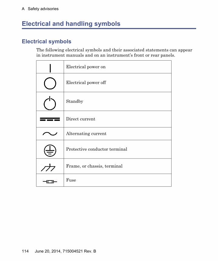
A Safety advisories
Electrical and handling symbols
Electrical symbols
The following electrical symbols and their associated statements can appear in instrument manuals and on an instrument’s front or rear panels.
Electrical power on
Electrical power off
Standby
Direct current
Alternating current
Protective conductor terminal
Frame, or chassis, terminal
Fuse
114 June 20, 2014, 715004521 Rev. B

Electrical and handling symbols
Handling symbols
The following handling symbols and their associated statements can appear on labels affixed to the packaging in which instruments, devices, and component parts are shipped.
Keep upright!
Keep dry!
Fragile!
Use no hooks!
June 20, 2014, 715004521 Rev. B 115

A Safety advisories
116 June 20, 2014, 715004521 Rev. B

B Specifications
The specifications presented here depend on the conditions in individual laboratories. Refer to the ACQUITY® UPC2™ System Site Preparation Guide, or contact the Waters® Technical Service organization for additional information about specifications.
Contents:
Topic Page
ACQUITY UPC2 system specifications .......................................... 117
Solvents to use with liquid CO2...................................................... 120
ACQUITY UPC2 binary solvent manager specifications ............... 123
ACQUITY UPC2 convergence manager specifications................... 126
ACQUITY column manager with active preheating and auxiliary column manager specifications ................................. 127
ACQUITY 30-cm single-zone column manager specifications ...... 129
ACQUITY UPC2 photodiode array detector specifications ........... 129
ACQUITY UPC2 sample manager - fixed loop specifications ....... 131
Physical specifications ..................................................................... 133
June 20, 2014, 715004521 Rev. B 117

B Specifications
ACQUITY UPC2 system specifications
ACQUITY UPC2 system specifications:
Feature Specifications
Operating flow rate range 0.010 to 4.000 mL/min, in 0.001-mL increments.
Maximum operating pressure and maximum flow rate
3.25 mL/minute up to 41,369 kPa (413 bar, 6000psi).4 mL/minute up to 29,303 kPa (293 bar, 4250psi).
Back pressure regulator Range: 10,000 to 400,000 kPa (100 to 400 bar, 1450 to 5801 psi)Noise: < ± 0.5 bar
Unattended operation Leak sensors, full 96-hour diagnostic data display through the console software
Liquid CO2 Minimum purity level of 99.97%
Instrument control specifications:
Feature Specification
External control EmpowerTM software or MassLynxTM software
External communications Ethernet interfacing via RJ45 connection to host PC
Event inputs/outputs Rear panel contact closure and/or TTL inputs/outputs
Connections INSIGHT® Provides real-time monitoring and automatic notification of instrument performance and diagnostic information, allowing for faster problem resolution.
118 June 20, 2014, 715004521 Rev. B

ACQUITY UPC2 system specifications
Electrical specifications:
Feature Specification
Protection class Class I: The insulating scheme used in the instrument to protect from electrical shock. Class I identifies a single level of insulation between live parts (wires) and exposed conductive parts (metal panels), in which the exposed conductive parts are connected to a grounding system. In turn, this grounding system is connected to the third pin (ground pin) on the electrical power cord plug.
Overvoltage category Class II: Pertains to instruments that receive their electrical power from a local level such as an electrical wall outlet.
Pollution degree 2: A measure of pollution on electrical circuits that can produce a reduction of dielectric strength or surface resistivity. Degree 2 refers only to normally nonconductive pollution. Occasionally, however, expect a temporary conductivity caused by condensation.
Moisture protection Normal (IPXO): IPXO means that no Ingress Protection against any type of dripping or sprayed water exists. The “X” is a placeholder that identifies protection against dust, if applicable.
Line voltages, nominal
Grounded AC.
Line voltage range 100 to 240 Vac.
Frequency UPC2 System and its modules: 50−60 Hz
June 20, 2014, 715004521 Rev. B 119

B Specifications
Solvents to use with liquid CO2
The following table identifies the recommended cosolvents to use with liquid CO2 in the ACQUITY UPC2 system. You can use up to 55% cosolvent with liquid CO2. When needed, use up to 5% of acceptable additives in the cosolvent.
Also listed are solvents that are not recommended for use in this system.
Maximum power draw • ccBSM: 200 VA• CM-A with active pre-heater: 400 VA• CM-30S: 600 VA• Convergence manager: 200 VA• PDA: 185 VA• SM-FL: 400 VA
Environmental specifications:
Feature Specification
Acoustic noise <65 dBA (single-stack, 5-module system)
Operating temperature range 15 to 28 °C (59 to 82.4°F)
Operating humidity 20 to 80%, non-condensing
Transportation and storage temperature −30 to 60 °C (−22 to 140 °F)
Transportation and storage humidity 10 to 85%, noncondensing
Shock (drop) per ASTM D 4169-90
Vibration per ASTM D 4169-90
Electrical specifications: (Continued)
Feature Specification
120 June 20, 2014, 715004521 Rev. B
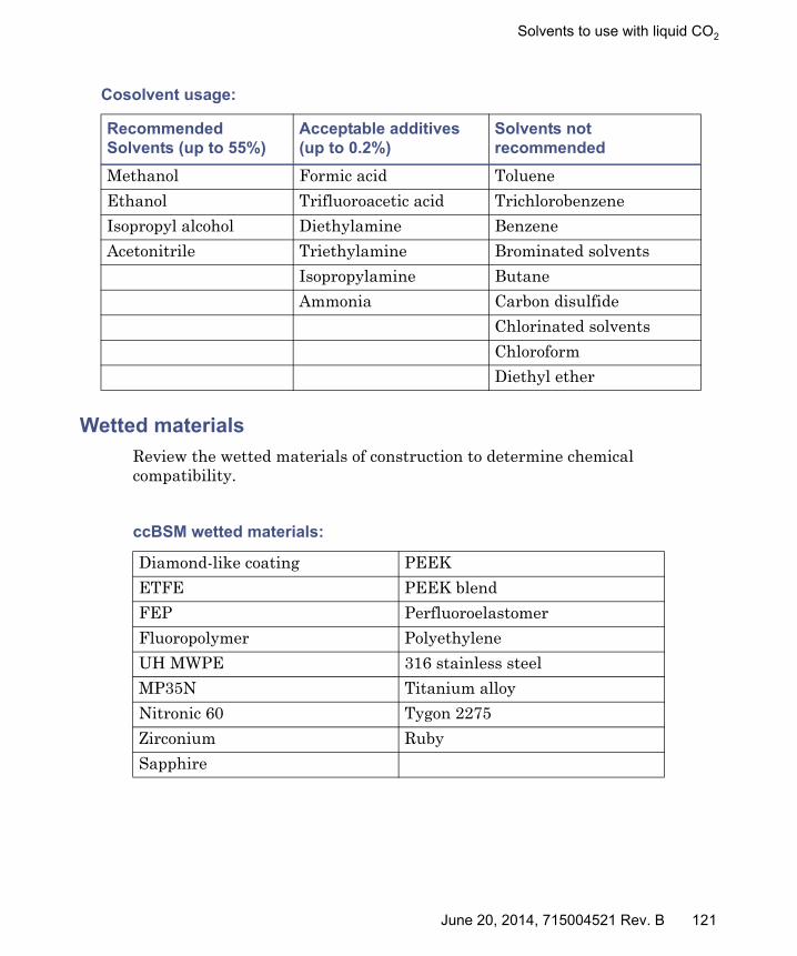
Solvents to use with liquid CO2
Wetted materials
Review the wetted materials of construction to determine chemical compatibility.
Cosolvent usage:
Recommended Solvents (up to 55%)
Acceptable additives (up to 0.2%)
Solvents not recommended
Methanol Formic acid Toluene
Ethanol Trifluoroacetic acid Trichlorobenzene
Isopropyl alcohol Diethylamine Benzene
Acetonitrile Triethylamine Brominated solvents
Isopropylamine Butane
Ammonia Carbon disulfide
Chlorinated solvents
Chloroform
Diethyl ether
ccBSM wetted materials:
Diamond-like coating PEEK
ETFE PEEK blend
FEP Perfluoroelastomer
Fluoropolymer Polyethylene
UH MWPE 316 stainless steel
MP35N Titanium alloy
Nitronic 60 Tygon 2275
Zirconium Ruby
Sapphire
June 20, 2014, 715004521 Rev. B 121

B Specifications
Convergence manager wetted materials:
Ceramic PEEK blend
Diamond-like coating PPS
Flouroelastomer 316 stainless steel
Fluoropolymer UHMWPE blend
Gold Vespel
Nitronic 60 Zirconia
PEEK
CM-30S wetted materials:
316 stainless steel PEEK
Diamond-like coating
SM-FL wetted materials:
Diamond-like coating PEEK™
Fluoroelastomer PPS
Fluoropolymer PPS Alloy
Gold 316 stainless steel
PEEK blend Titanium alloy
122 June 20, 2014, 715004521 Rev. B

ACQUITY UPC2 binary solvent manager specifications
ACQUITY UPC2 binary solvent manager specifications
ccBSM performance specifications:
Feature Specification
Number of solvents (cosolvent pump only)
Liquid CO2 on the A side of the pump. The CO2 high-pressure inlet connects to the rear panel of the convergence manager.As many as four cosolvents on the B side of the pump, labeled B1, B2, B3, and B4.
Priming No priming needed on the A side pump for CO2 solvent: The CO2 inlet pressure from the convergence manager is typically between 750 and 1200 psi, not to exceed 1300psi.Prime only the B side of the pump (cosolvents). Wet priming can run at flow rates up to 4 mL/minute.
Leak management Drip trays manage all leaks from the pump into a drain tube that is directed either to the front or rear of the module where it empties into a waste container.
Leak detector Integrated into the drip tray.
Pump synchronization The ccBSM pump cycle synchronizes with the SM-FL injection cycle to enhance retention time reproducibility.
Solvent conditioning (cosolvent pump only)
Integrated vacuum degassing, four chambers.
Gradient formation High pressure mixing, binary gradient.
Gradient profiles 11 gradient curves, including linear, step (2), concave (4), and convex (4).
Mixing options Standard: 250 μL
Primary check valves • Active inlet check valve on the cosolvent primary pump uses Intelligent Intake Valves (i2Valve)
• Passive check valves on each accumulator pump
June 20, 2014, 715004521 Rev. B 123
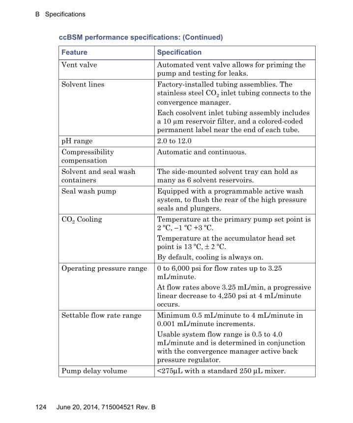
B Specifications
Vent valve Automated vent valve allows for priming the pump and testing for leaks.
Solvent lines Factory-installed tubing assemblies. The stainless steel CO2 inlet tubing connects to the convergence manager.Each cosolvent inlet tubing assembly includes a 10 μm reservoir filter, and a colored-coded permanent label near the end of each tube.
pH range 2.0 to 12.0
Compressibility compensation
Automatic and continuous.
Solvent and seal wash containers
The side-mounted solvent tray can hold as many as 6 solvent reservoirs.
Seal wash pump Equipped with a programmable active wash system, to flush the rear of the high pressure seals and plungers.
CO2 Cooling Temperature at the primary pump set point is 2 ºC, −1 ºC +3 ºC.Temperature at the accumulator head set point is 13 ºC, ± 2 ºC.By default, cooling is always on.
Operating pressure range 0 to 6,000 psi for flow rates up to 3.25 mL/minute. At flow rates above 3.25 mL/min, a progressive linear decrease to 4,250 psi at 4 mL/minute occurs.
Settable flow rate range Minimum 0.5 mL/minute to 4 mL/minute in 0.001 mL/minute increments.Usable system flow range is 0.5 to 4.0 mL/minute and is determined in conjunction with the convergence manager active back pressure regulator.
Pump delay volume <275μL with a standard 250 μL mixer.
ccBSM performance specifications: (Continued)
Feature Specification
124 June 20, 2014, 715004521 Rev. B

ACQUITY UPC2 binary solvent manager specifications
Flow precision 0.075% RSD or ± 0.02 minutes standard devia-tion, which ever is greater, based on six replicates.
Composition range 0.0 to 100% of the cosolvent settable in 0.1% increments.Cosolvent solubility dependent.
Composition precision 0.15% RSD or ± 0.04 minute standard devia-tion, whichever is greater, based on 6 repeat injections.
ccBSM Input/Output specifications:
Attribute Specification
Run stopped output • Maximum voltage: 30 VDC• Maximum current: 0.5 A• Maximum VA rating: 10 W• Contact resistance (nominal): 0.2 ohms• Screw terminal connectorBehavior: If an error message exists, the switch closes, and then opens when the error is cleared.
Stop flow input TTL signal or contact closure:• Input voltage range: ±30 VDC• Logic High: ≥3.0 VDC• Logic Low: ≤1.9 VDC• Minimum pulse width: 100 msec• Screw terminal connector
Start gradient input Same as Stop flow input.
Ethernet RJ45 connector
ccBSM performance specifications: (Continued)
Feature Specification
June 20, 2014, 715004521 Rev. B 125

B Specifications
ACQUITY UPC2 convergence manager specifications
Convergence manager performance specifications:
Feature Specification
CO2 pressure relief Monitors CO2 pressure and relieves overpressure that exceeds safe limits by venting it to waste or an external CO2 vent.
Relief pressure: 1750 psi +/− 250 psi
CO2 shutoff valve Turns on and shuts off the CO2 automatically when the system is powered off or when it encounters an error.
CO2 inlet pressure transducer
Measurement range: −124 to 1190 psiResolution: 10 psiAccuracy: +/− 30 psi at full scaleMaximum working pressure: 2000 psi
System vent valve Vents the system to waste before the automatic back pressure regulator (ABPR). The vent valve automatically opens when the convergence manager is shut off or the system flow stops.
Automatic back pressure regulator (ABPR) sensor
Measures system pressure before the ABPR operation ensuring that the pressure does not exceed pressure performance specifications.
ABPR Dynamic regulating valve
Adjusts the system pressure to compensate for thermal and solvent composition changes when delivering pressure gradients.
ABPR Static regulating valve.
Maintains the dynamic valve pressure to that above the critical pressure of CO2.
ABPR heating system Maintains the temperature of the static regulator at a set elevated temperature range during the CO2 liquid-to-gas phase transition to prevent the cosolvents from freezing.ABPR heater:
Temperature stability: +/− 2.0°C
126 June 20, 2014, 715004521 Rev. B

ACQUITY column manager with active preheating and auxiliary column manager specifications
ACQUITY column manager with active preheating and auxiliary column manager specifications
ABPR operating pressures Minimum: 1500 psiMaximum: 6000 psi
ABPR flow rate operating range
Minimum: 0.5 mL/minuteMaximum flow rate: 4.0 mL/minute
Leak management Drip trays manage all leaks from the convergence manager into a drain tube at the front of the module and empties the liquid into a user-supplied waste container.
Column manager performance specifications:
Feature Specification
Column 2.1 to 4.6 mm I.D. up to 150 mm in lengthWith guard column OR filter 30 mm length max.
Columns capacity CM-A: Two columns, as standard (maximum length of 150 mm with filter or guard column) or four columns (maximum length of 50 mm) with the optional tubing kit, up to 4.6 mm internal diameter (I.D.).CM-Aux: Two columns (maximum length of 150 mm, with filter or guard column). As many as two CM-Aux units can be configured with one CM-A to support as many as six columns.
Switching valves Two injector style, nine-port, eight-position valves (CM-A only); provides programmable automatic, random-access switching; waste and bypass positions for rapid solvent changeover.
Convergence manager performance specifications: (Continued)
Feature Specification
June 20, 2014, 715004521 Rev. B 127

B Specifications
Column compartment(s) temperature range
4.0 to 90.0 °C, settable in 0.1 °C increments; two independent heat/cool zones per module, up to six zones in a stacked configuration.
Column compartment(s) temperature accuracy
±0.5 °C
Column compartment precision
±0.1°C
Column compartment(s) temperature stability
±0.3 °C
Solvent conditioning Active pre-heating as standard.
Column tracking eCord™ Technology column information management tracks and archives achiral Viridis™ column usage history.
Column manager performance specifications: (Continued)
Feature Specification
128 June 20, 2014, 715004521 Rev. B

ACQUITY 30-cm single-zone column manager specifications
ACQUITY 30-cm single-zone column manager specifications
ACQUITY UPC2 photodiode array detector specifications
CM-30S performance specifications:
Feature Specification
Column capacity Eight selectable columns when bypass and waste are omitted. Up to 4.6 mm internal diameter (ID), up to 300 mm in length with filter or guard column.
Fittings 124,106 kPa (1241 bar, 18,000 psi), low dispersion, with reusable column inlet fittings.
Column compartment temperature range
20.0 to 90.0 °C, settable in 0.1 °C increments.
Column compartment temperature accuracy
±0.5 °C
Column compartment temperature stability
±0.5 °C
Solvent conditioning Passive pre-heating
Column tracking eCordTM Technology column information management tracks and archives column usage history.
PDA performance specifications:
Item Specification
Data rate ≤ 80 Hz Max
Digital filter Variable with data rate
Digital resolution 1.2, 2.4, 3.6, 4.8, 6.0, 7.2, 8.4, 9.6, 10.8, 12.0 nm
Drifta (dry) ≤1000 μAU/hr (at 230 nm, 2 Hz, 1 sec TC, 3.6 nm res, dry analytical flow cell); 2 hr warm-up, envi-ronmental stability <±2 °C/hr variation
June 20, 2014, 715004521 Rev. B 129

B Specifications
Linearity ≤5% at 2.0 AU, propylparaben series at 257 nm, 10 mm analytical flow cell
Nitrogen purge Purge fitting present on optics bench and rear panel
Noise (wet) <10 μAU (254 nm, 2 Hz, 1 sec TC, 3.6 BW res, 10 mm analytical flow cell) flow rate 0.5 mL/min, 90:10 H2O:ACN
Optical resolution 1.2 nm (nominal), with 50-μm slit
Order filter Fixed, 370 nm to 800 nm
Photodetector 512 element selective access photodiode array
Wavelength accuracy ±1.0 nm (tested with Erbium Perchlorate)
Wavelength calibration filter
Erbium filter, used at startup or on-demand
Wavelength range 190 to 800 nm
Wavelength repeatability
±0.1 nm
a. ASTM drift tests require a temperature change of less than 2 °C/hour (3.6 °F/hour) over a one hour period. Larger ambient changes will result in larger drift. Better drift performance depends on better control of temperature fluctuations. To realize the highest performance, minimize the frequency and the amplitude of temperature changes to below 1 °C/hour (1.8 °F/hour). Turbulences around one minute or less can be ignored.
PDA performance specifications: (Continued)
Item Specification
130 June 20, 2014, 715004521 Rev. B

ACQUITY UPC2 sample manager - fixed loop specifications
ACQUITY UPC2 sample manager - fixed loop specifications
SM-FL performance specifications:
Feature Specification
Integrated leak management
Leak sensors, as standard, and safe leak handling. Drip trays direct all leaks to the front of the instrument, and then into the waste line.
Operating flow rate range 0.010 to 4.000 mL/min, in 0.001 mL increments.
Maximum operating pressure
41,369 kPa (413 bar, 6000psi) up to 3.25 mL/minute.
pH range pH 2 to 12.
Unattended operation Leak sensors, full 96-hour diagnostic data display through the console software.
Number of sample plates Total of two plates:• 96 and 384 microtiter plates• 48 position 2.00-mL vial plates• 48 position 0.65-mL micro-centrifuge tube
plates• 24 position 1.50-mL micro-centrifuge tube
plates
Maximum sample capacity 768 in two 384-well plates.
Injection volume range 0.1 to 50.0 μL, in 0.1-μL increments; 10-μL loop is standard.
Injection mode Partial Loop Uses Needle Overfill Mode (default mode) - used for optimal quantitation using partial loop injection volumes.
Sample delivery precision <1% peak area RSD within 20% to 75% of loop volume for 10-μL loops, UV detection.
Injection linearity >0.999 coefficient of deviation (from 20% to 75%) based on peak area.
Wash solvents Two degassed: strong solvent and weak wash solvent, programmable to suit the application.
June 20, 2014, 715004521 Rev. B 131
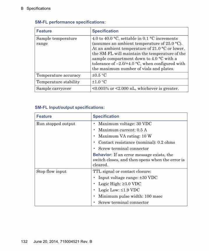
B Specifications
Sample temperature range
4.0 to 40.0 °C, settable in 0.1 °C increments (assumes an ambient temperature of 25.0 °C). At an ambient temperature of 21.0 °C or lower, the SM-FL will maintain the temperature of the sample compartment down to 4.0 °C with a tolerance of −2.0/+4.0 °C, when configured with the maximum number of vials and plates.
Temperature accuracy ±0.5 °C
Temperature stability ±1.0 °C
Sample carryover <0.005% or <2.000 nL, whichever is greater.
SM-FL Input/output specifications:
Feature Specification
Run stopped output • Maximum voltage: 30 VDC• Maximum current: 0.5 A• Maximum VA rating: 10 W• Contact resistance (nominal): 0.2 ohms• Screw terminal connectorBehavior: If an error message exists, the switch closes, and then opens when the error is cleared.
Stop flow input TTL signal or contact closure:• Input voltage range: ±30 VDC• Logic High: ≥3.0 VDC• Logic Low: ≤1.9 VDC• Minimum pulse width: 100 msec• Screw terminal connector
SM-FL performance specifications:
Feature Specification
132 June 20, 2014, 715004521 Rev. B

Physical specifications
Physical specifications
Review the physical instrument module specifications and observe all safety advisories.
Note: The ACQUITY UPC2 System requires a 6 inch minimum rear clearance for operation.
Warning: To avoid back injuries, do not attempt to lift the devices without assistance.
ccBSM physical specifications:
Attribute Specification
Height 22.9 cm (9 inches)
Width 34.3 cm (13.5 inches)
Depth 66 cm (26 inches)
Weight 33 kg (less than 75 pounds)
CM-A physical specifications:
Attribute Specification
Height 19.9 cm (7.8 inches)
Width 34.3 cm (13.5 inches)
Depth 61.0 cm (24.0 inches)
Weight 20.9 kg (46.0 pounds)
CM-AUX physical specifications:
Attribute Specification
Height 13.7 cm (5.4 inches)
Width 34.3 cm (13.5 inches)
Depth 61.0 cm (24.0 inches)
June 20, 2014, 715004521 Rev. B 133

B Specifications
Weight 11.4 kg (25.0 pounds)
CM-30S physical specifications:
Attribute Specification
Height 71.9 cm (28.3 inches)
Width 23.6 cm (9.3 inches)
Depth 61.5 cm (24.2 inches)
Weight 43.1 kg (95.0 pounds)
PDA physical specifications:
Attribute Specification
Height 19.3 cm (7.6 inches)
Width 34.3 cm (13.5 inches)
Depth 60.7 cm (23.9 inches)
Weight 15.9 kg (35.0 pounds)
SM-FL physical specifications:
Attribute Specification
Height 27.1 cm (10.7 inches)
Width 34.3 cm (13.6 inches)
Depth 71.2 cm (28.0 inches)
Weight 25.9 kg (57.0 pounds)
CM-AUX physical specifications: (Continued)
Attribute Specification
134 June 20, 2014, 715004521 Rev. B

C Configuring the core 4 system variant
The UPC2 core 4 configuration variant has two 30-cm single-zone column managers instead of one. Because of this, it is frequently referred to as a dual CM-30S with primary and secondary ovens.
Contents:
Topic Page
Physical arrangement...................................................................... 136
Column configuration ...................................................................... 137
Configuring software for dual column managers ........................... 138
June 20, 2014, 715004521 Rev. B 135

C Configuring the core 4 system variant
Physical arrangement
Example of the core 4 configuration system variant:
�������
Solvent tray
PDA
Convergence manager
SM-FL
ccBSM
Primary ovenCM-30S (1)
Secondary oven CM-30S (2)
136 June 20, 2014, 715004521 Rev. B

Column configuration
Column configuration
Dual CM-30S supporting 15 columns with bypass and waste omitted:
June 20, 2014, 715004521 Rev. B 137

C Configuring the core 4 system variant
Configuring software for dual column managers
Column manager software must be configured to define the path of the solvents and samples as they flow through the inlet and outlet valves. The following procedure applies only to UPC2 systems with two 30-cm single-zone column managers running Empower software.
See also: To configure software for a system with one column manager, see the console online Help.
Requirement: Use Empower 3, FR2 or later.
Set a primary and secondary column manager
The primary column manager serves as the inlet from the SM-FL. Samples and solvents flow through the primary column manager valves, and then are routed to the secondary column manager.
Requirement: When you power-on your system hardware, you must press the power button on the secondary column manager first, followed by the primary column manager second.
To configure the chromatographic system:
1. In Empower, start the system configuration procedure.
2. On the Configuration tab, drag and drop the primary column manager name from the Available Components pane to the System Configuration pane. Drag and drop the secondary column manager name to the System Configuration pane.
Requirement: The primary column manager must be listed before the secondary column manager in the System Configuration pane.
3. Drag and drop the names of other system components to the System Configuration pane in any order.
4. Complete the system configuration.
To confirm the serial number of the primary column manager:
1. From the console system tree, select System.
138 June 20, 2014, 715004521 Rev. B

Configuring software for dual column managers
2. From the Configure menu, select Primary column manager.
Result: The two column managers are listed, and the primary column manager has a check mark next to it.
Tip: You can rename modules when there are two or more of the same type. In the console system tree, double-click the module, edit the name, and then press ENTER. The new name appears throughout console and in the control panels.
Configure the operating mode for each column manager
In this procedure, you configure the software to match the fluidic configuration of the dual system. This enables the software to switch between up to 15 columns, contained within the two column managers.
To configure the operating mode in a dual CM-30S UPC2 system:
1. From the console system tree, select the primary column manager.
2. From the Configure menu, select Operating mode.
3. In the Operating Mode Configuration dialog box, under “Select mode of operation”, select “Column Selection”.
4. Select Bypass, and then ensure Banked and Waste selections are not selected.
Result: The bypass port connects the outlet of the primary column manager to the inlet of the secondary column manager. Bypass is now an invalid Column Selection position.
5. Click OK.
6. From the console system tree, select the secondary CM-30S.
7. From the Configure menu, select Operating mode.
8. In the Operating Mode Configuration dialog box, under “Select mode of operation”, select “Column Selection”.
9. Ensure Banked, Bypass, and Waste selections are not selected, and then click OK.
June 20, 2014, 715004521 Rev. B 139
C Configuring the core 4 system variant
10. Enable the leak sensors for each column manager.
Tip: If the Run Samples window is open, close the window and reopen it to update the Column Position column in run samples.
See also: For detailed instructions, see the console online Help.
Recommendation: You must recycle power to the workstation after configuring software for a column manager.
Result: After completing this procedure, when you select each column manager in the console system tree, the columns appear. The primary column manager is listed first with Columns 1 through 7 available. The secondary column manager is listed second with Columns 1 through 8 available.
Exception: To run the ABPR health test, select Bypass for both column managers.
See also: “Running an ABPR health test when the system includes a 30-cm single-zone column manager”on page 98.
Select a column
You can use only one column at a time. The software is programmed to limit your selection to one column. An alarm will appear if you select one column in each column manager.
You select a column in the instrument method editor or in the control panel. Then, for the column manager that does not control this column, you select None. This stops the flow of sample and solvent to the unused column manager.
Example: Select a column in the primary column manager, then select None in the secondary primary manager.
Selecting a column before running system startup
Requirement: Make sure you select a valid column combination before you run the system startup feature.
To select a column before running the system startup:
1. From the Console tree, select the system.
2. From the Control menu, select Start up system.
3. On the Equilibrate to Method tab of the System Startup dialog box select the CM and CM-2 subtabs.
140 June 20, 2014, 715004521 Rev. B

Configuring software for dual column managers
4. For the Column Selection, select the column number or select None.
5. Make any needed changes on the other subtabs, and then click Start to begin the system startup.
Selecting a column in instrument method editors
To select a column in instrument method editors:
1. Select the column manager instrument method editor that controls the column.
Tip: In most cases, the primary column manager instrument method editor is named ACQ-CM and the secondary column manager is named ACQ-CM-2.
2. Select the General tab.
3. Select the Column Selection mode.
4. In the Column Selection area, in the Valve Position field, select the column number.
Restriction: Do not select the Bypass position on the primary CM-30S. In a dual configuration, the bypass port is used to direct flow from the outlet of the primary column manager to the inlet of the secondary column manager. The Bypass selection is therefore invalid, and selecting Bypass will result in an alarm.
5. Select the column manager instrument editor that does not contain the column.
6. Select the General tab.
7. Select the Column Selection mode.
8. In the Column Selection area, in the Valve Position field, select “None” to indicate that a column in the other column manager will be used.
Restriction: Do not select Bypass.
Selecting a column in control panel or console
When you select a column in a control panel, the Column Selection field in the other column manager’s control panel automatically updates to None.
June 20, 2014, 715004521 Rev. B 141

C Configuring the core 4 system variant
Example:
Recovering from a “Multi mode column selection is out of range” alarm
When you select a new column, the alarm “Multi mode column selection is out of range CM(x) CM(y)” can appear. x is the column selected for the primary column manager, and y is the column selected for the secondary column manager.
If this alarm appears, you have entered one of the following invalid combinations into the two column managers:
• Bypass and column number
• Column number and column number
• None and None
Tip: Selecting No Change is equivalent to selecting a column, because No Change directs the system to use the current column.
“Multi mode column selection is out of range” alarms:
Column Selection Situation Resolution
Instrument methodControl panelConsoleSystem startup
You selected Bypass in one column manager and a column number or No Change in the other column manger.
Replace Bypass with None.
142 June 20, 2014, 715004521 Rev. B

Configuring software for dual column managers
Run a sample queue
Prior to running a sample queue, the Instrument Matching wizard appears so you can associate the primary and secondary column managers’ physical addresses with the instrument method.
To match the column managers’ addresses to the instrument method:
1. In the Empower Run Samples dialog box, from the Inject menu, select Run Sample Set.
Alternative: Click (Run).
2. When the Instrument Matching wizard appears, click Next.
Result: “ACQ-CM”, indicating the first column manager, appears in the Channel field.
3. Select the primary column manager from the table, and then click Next.
Requirement: If the primary column manager is not listed first in the table, the system is not configured correctly. Follow the procedure “Set a primary and secondary column manager”on page 138.
Result: “ACQ-CM-2”, indicating the second column manager, appears in the Channel field.
4. Select the secondary column manager from the table, and then click Finish.
Instrument methodSystem startup
You selected a column number or No Change in both column managers.
Select None in one of the column managers.
Instrument methodSystem startup
You selected None in both column managers.
Select a column in one of the column managers.
“Multi mode column selection is out of range” alarms:
Column Selection Situation Resolution
June 20, 2014, 715004521 Rev. B 143

C Configuring the core 4 system variant
144 June 20, 2014, 715004521 Rev. B