acs100 manual eng
TRANSCRIPT

8/10/2019 ACS100 Manual Eng
http://slidepdf.com/reader/full/acs100-manual-eng 1/52
Comp-AC User’s Manualfor type ACS 100
frequency convertersfrom 0.12 to 2.2 kW

8/10/2019 ACS100 Manual Eng
http://slidepdf.com/reader/full/acs100-manual-eng 2/52
8/10/2019 ACS100 Manual Eng
http://slidepdf.com/reader/full/acs100-manual-eng 3/52
ACS 100 Frequency Converter
User’s Manual
3BFE 64307622 R0125
EN
Effective: 8.3.2000
© 2000 ABB Industry Oy

8/10/2019 ACS100 Manual Eng
http://slidepdf.com/reader/full/acs100-manual-eng 4/52

8/10/2019 ACS100 Manual Eng
http://slidepdf.com/reader/full/acs100-manual-eng 5/52
i
Safety
Warning! Only a competent electrician may install the ACS 100.
Warning! Dangerous voltages are present when mains supply is
connected. Wait at least 5 minutes after disconnecting the supply before
removing the cover. Measure the voltage at DC terminals (Uc+, Uc-) before
servicing the unit (see G).
Warning! Even when the motor is stopped there are dangerous
voltages present at Power Circuit terminals U1, V1, W1 (L,N) and U2, V2, W2
and Uc+
, Uc-
.
Warning! Even when the ACS 100 is powered down, there may be
dangerous external voltages at relay terminals RO1, RO2, RO3.
Warning! The ACS 100 is not a field repairable unit. Never attempt to
repair a broken unit; contact the supplier for replacement of the unit.
Warning! The ACS 100 will start up automatically after an input
voltage interruption if the external run command is on.
Warning! When the control terminals of two or more ACS100 / 140 /
400 units are connected in parallel, the auxiliary voltage for these control
connections must be taken from a single source which can either be one of
the units or an external supply.
Warning! Altering the parameter settings or device configurations wi ll
affect the function and performance of the ACS 100. Check that these
changes do not cause any risk to persons or property.
Warning! The heat sink may reach a high temperature (see S).
Note! For more technical information, contact the supplier.

8/10/2019 ACS100 Manual Eng
http://slidepdf.com/reader/full/acs100-manual-eng 6/52
ii
8/10/2019 ACS100 Manual Eng
http://slidepdf.com/reader/full/acs100-manual-eng 7/52
iii
Table of Contents
Safety ................................................................. i
Installation ........................................................ 1
Reference Sections.......................................... 2
Environmental Limits .................................................. 2
Dimensions (mm) ....................................................... 2
Installing the ACS 100................................................ 3
Removing the Cover................................................... 6
Attaching a Warning Sticker ....................................... 6
Cable Connections ..................................................... 6
Terminal Interface ...................................................... 7
Type Designation Label and Code Key...................... 8
Floating Network ........................................................ 8
Motor .......................................................................... 8
Control Terminals ....................................................... 9
Configuration Switch ................................................ 10
Connection Examples .............................................. 11
Replacing the Cover................................................. 11
Power On ................................................................. 12
Protection Features .................................................. 12
Motor Overload Protection ....................................... 13
Loadability of ACS 100............................................. 13
Type Series and Technical Data .............................. 14Product Conformity................................................... 17
Environmental Information ....................................... 17
Accessories .............................................................. 18
Programming.................................................. 19
Control Panel ................................................... 19
Control Modes .......................................................... 19
Output Display.......................................................... 20
Menu Structure......................................................... 20
Setting Parameter Value .......................................... 20
Menu Functions........................................................ 21
Diagnostic Displays .................................................. 21Resetting the Drive................................................... 22
ACS 100 Parameter Table ............................... 23
Group 01: Actual Values and Status ........................ 25
Group 02: Motor Values and Limits.......................... 25
Group 03: Drive Control ........................................... 26
Group 04: Input/Output............................................. 27
Group 05: Supervision.............................................. 28

8/10/2019 ACS100 Manual Eng
http://slidepdf.com/reader/full/acs100-manual-eng 8/52
iv
Diagnostics....................................................... 31
General .................................................................... 31
Alarm and Fault displays.......................................... 31
Fault Resetting ......................................................... 31
ACS 100 EMC Instructions............................. 35
8/10/2019 ACS100 Manual Eng
http://slidepdf.com/reader/full/acs100-manual-eng 9/52
1
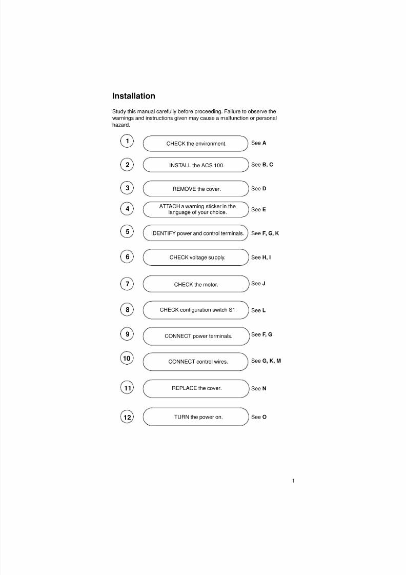
Installation
Study this manual carefully before proceeding. Failure to observe the
warnings and instructions given may cause a malfunction or personal
hazard.
1
2
3
5
6
7
8
9
11
12
CHECK the environment.
INSTALL the ACS 100.
REMOVE the cover.
CHECK voltage supply.
CHECK the motor.
IDENTIFY power and control terminals.
CHECK configuration switch S1.
CONNECT control wires.
CONNECT power terminals.
REPLACE the cover.
TURN the power on.
See A
See B, C
See D
See F, G, K
See H, I
See J
See L
See F, G
See G, K, M
See N
See O
10
4 ATTACH a warning sticker in the
See Elanguage of your choice.
8/10/2019 ACS100 Manual Eng
http://slidepdf.com/reader/full/acs100-manual-eng 10/52
2
Reference Sections
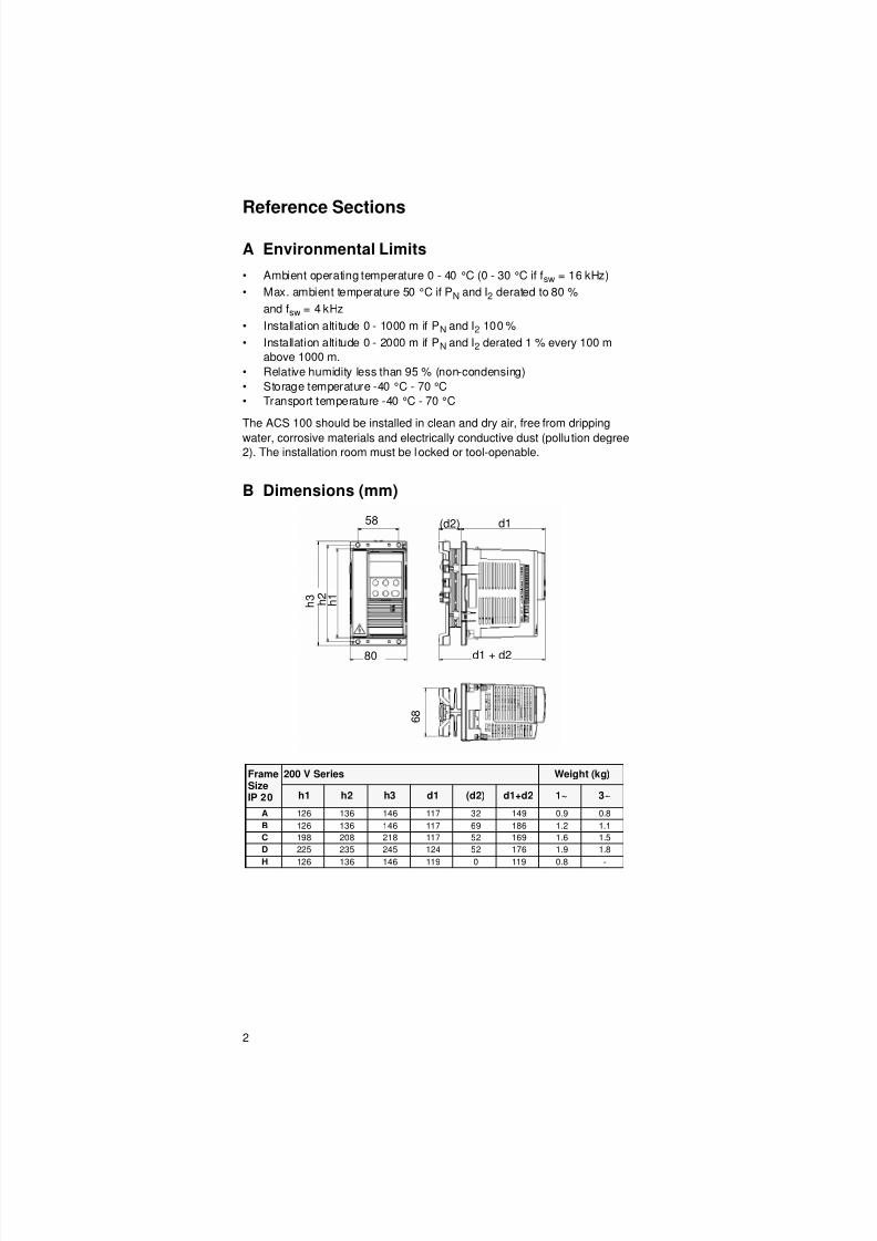
A Environmental Limits
• Ambient operating temperature 0 - 40 °C (0 - 30 °C if fsw = 16 kHz)
• Max. ambient temperature 50 °C if PN and I2 derated to 80 %
and fsw = 4 kHz
• Installation altitude 0 - 1000 m if PN and I2 100 %
• Installation altitude 0 - 2000 m if PN and I2 derated 1 % every 100 m
above 1000 m.
• Relative humidity less than 95 % (non-condensing)
• Storage temperature -40 °C - 70 °C
• Transport temperature -40 °C - 70 °C
The ACS 100 should be installed in clean and dry air, free from dripping
water, corrosive materials and electrically conductive dust (pollu tion degree2). The installation room must be locked or tool-openable.
B Dimensions (mm)
FrameSizeIP 20
200 V Series Weight (kg)
h1 h2 h3 d1 (d2) d1+d2 1~ 3~
A 126 136 146 117 32 149 0.9 0.8
B 126 136 146 117 69 186 1.2 1.1
C 198 208 218 117 52 169 1.6 1.5
D 225 235 245 124 52 176 1.9 1.8
H 126 136 146 119 0 119 0.8 -
d1 + d2
6 8
(d2)
h 1
d1
h 2
h 3
58
80

8/10/2019 ACS100 Manual Eng
http://slidepdf.com/reader/full/acs100-manual-eng 11/52
3
C Installing the ACS 100
Warning! Before installing the ACS 100 ensure that the mains supply
to the installation is off.
Standard Series (Frame sizes A, B, C and D)
Install the ACS 100 vertically. Leave 25 mm free space above and below the
unit. Ensure that there is sufficient cool air in the cabinet to compensate for
the power losses (power and control circuits) l isted at the end of section S,
“Technical Data”.
Wall mounting
Use M4 screws
DIN rail (35 mm)
Press the lever on top of the unit while installing on / removing from DIN rail .

8/10/2019 ACS100 Manual Eng
http://slidepdf.com/reader/full/acs100-manual-eng 12/52
4
Flange mounting
The ACS 100 can be installed so that the heat sink is in an air duct. The
power circuit losses will then be dissipated outside leaving only the control
circuit losses to be dissipated inside (see S).
Heatsinkless series (Frame size H)
Note! The frame size H does not include the heatsink. The
heatsinkless ACS 100 is intended for applications where an external
heatsink is available. Ensure that the area of installation fulfils the heat
dissipation requirements.
Mounting Surface Requirements
Install the heatsinkless ACS 100 on an uncoated, clean metallic surface that
fulfils the following requirements:
• A minimum thickness of 3 mm.
• The surface must be stiff and flat. (max. flatness error 0.1 and max.
roughness Ra 3.2 µm)
∅5 or M44 holes
8/10/2019 ACS100 Manual Eng
http://slidepdf.com/reader/full/acs100-manual-eng 13/52
5
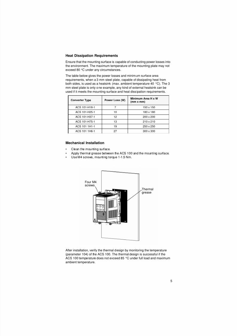
Heat Dissipation Requirements
Ensure that the mounting surface is capable of conducting power losses into
the environment. The maximum temperature of the mounting plate may not
exceed 80 °C under any circumstances.
The table below gives the power losses and minimum surface area
requirements, when a 3 mm steel plate, capable of dissipating heat from
both sides, is used as a heatsink (max. ambient temperature 40 °C). The 3
mm steel plate is only one example, any kind of external heatsink can be
used if it meets the mounting surface and heat dissipation requirements.
Mechanical Installation
• Clean the mounting surface.
• Apply thermal grease between the ACS 100 and the mounting surface.
• Use M4 screws, mounting torque 1-1.5 Nm.
After installation, verify the thermal design by monitoring the temperature
(parameter 104) of the ACS 100. The thermal design is successful if the
ACS 100 temperature does not exceed 85 °C under full load and maximum
ambient temperature.
Converter Type Power Loss (W)Minimum Area H x W(mm x mm)
ACS 101-H18-1 7 150 x 150
ACS 101-H25-1 10 180 x 180
ACS 101-H37-1 12 200 x 200ACS 101-H75-1 13 210 x 210
ACS 101-1H1-1 19 250 x 250
ACS 101-1H6-1 27 300 x 300
Thermalgrease
Four M4screws
8/10/2019 ACS100 Manual Eng
http://slidepdf.com/reader/full/acs100-manual-eng 14/52
6
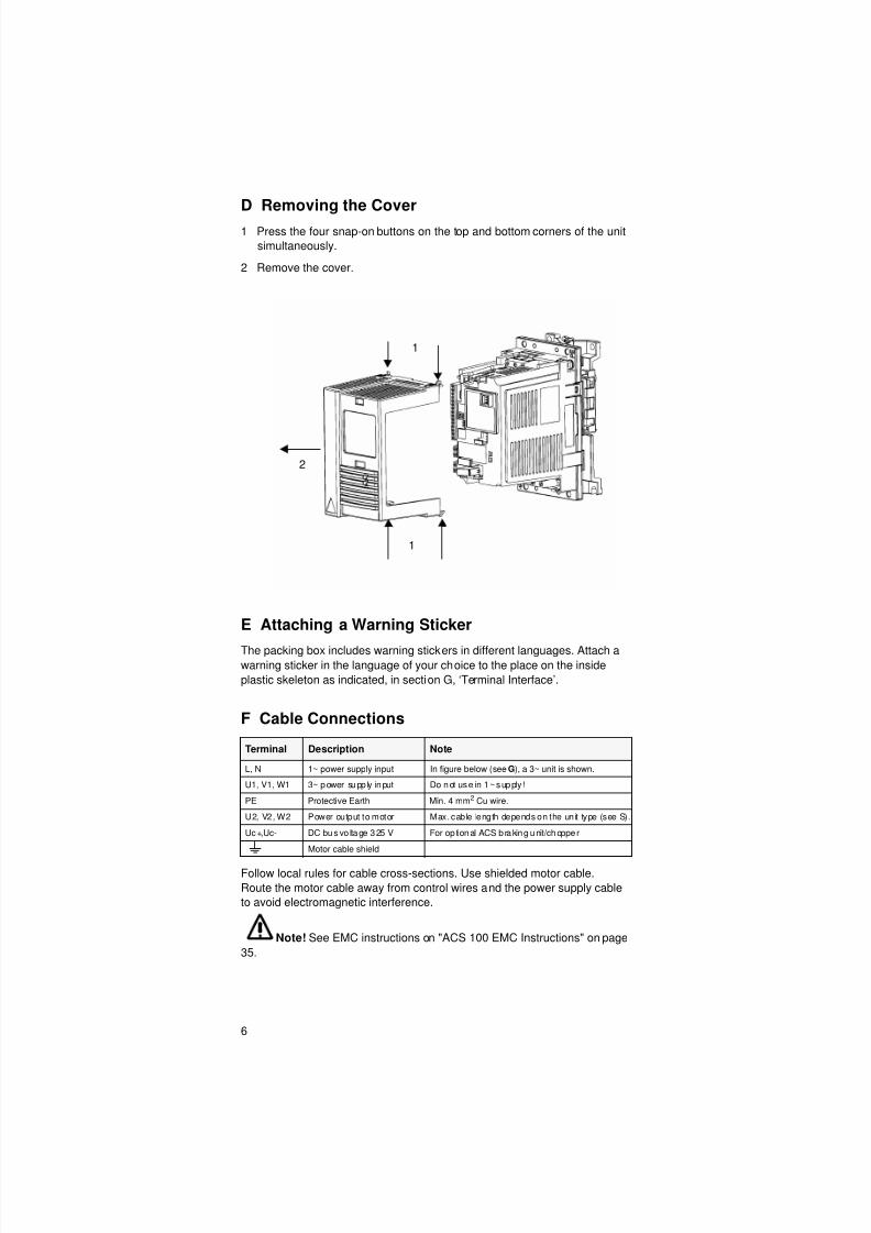
D Removing the Cover
1 Press the four snap-on buttons on the top and bottom corners of the unit
simultaneously.
2 Remove the cover.
E Attaching a Warning Sticker
The packing box includes warning stickers in different languages. Attach awarning sticker in the language of your choice to the place on the inside
plastic skeleton as indicated, in section G, ‘Terminal Interface’.
F Cable Connections
Follow local rules for cable cross-sections. Use shielded motor cable.
Route the motor cable away from control wires and the power supply cable
to avoid electromagnetic interference.
Note! See EMC instructions on "ACS 100 EMC Instructions" on page
35.
Terminal Description Note
L, N 1~ power supply input In figure below (see G), a 3~ unit is shown.
U1, V1, W1 3~ power supp ly input Do not use in 1~ supply !
PE Protective Earth Min. 4 mm2 Cu wire.
U2, V2, W2 Power output to motor Max. cable length depends on the unit type (see S).
Uc+,Uc- DC bus vo ltage 325 V For op tional ACS braking unit/chopper
Motor cable shield
1
2
1

8/10/2019 ACS100 Manual Eng
http://slidepdf.com/reader/full/acs100-manual-eng 15/52
7
G Terminal Interface
Red LED
Green LED
ABBABB Industry Oy
ACS103-1K6-1
U1 3* 230 V U2 3*0..U1
f1 50/60 Hz f2 0..300 Hz
I1 5.3 A I2 4.3 A
S/N 048A0001
Warning! Dangerous voltageWait 5 minutes after
disconnecting supply
before proceeding. See
User´s Manual.
DC terminalsfor optional ACSbraking unit/ chopper
Warning
Sticker
Power outputto motor
Control
Terminals,
see K
1
15
Switch S1
Configuration
Motor Cable
Shield
Power supply input
ProtectiveEarth
X 1

8/10/2019 ACS100 Manual Eng
http://slidepdf.com/reader/full/acs100-manual-eng 16/52
8
H Type Designation Label and Code Key
I Floating Network
If the supply network is floating (IT network) remove the grounding
screw (GND). Failure to do so may cause danger or damage the unit.
In floating networks do not use RFI filter. The mains becomes connected to
earth through the filter capacitors. In floating networks this may cause
danger or damage the unit.
Make sure that no excessive emission is propagated to neighbouring low
voltage networks. In some cases, the natural suppression in transformers
and cables is sufficient. If in doubt, a supply transformer with static screening
between the primary and secondary windings can be used.
J MotorCheck that the motor is compatible. The motor must be a three-phase
induction motor, with UN from 200 to 240 V and fN either 50 Hz or 60 Hz. If
the motor values differ from these, the group 02 parameter values must be
changed.
The motor nominal current, IN, must be less than or equal to the nominal
output current of the ACS 100, I2 (See H and S).
Supply:
ACS 101 = 1 ~
ACS 103 = 3 ~
Power:
1K6 = 1.6 kVA standard
series (frames A, B, C
and D)
1H6 = 1.6 kVA
heatsinkless series
(frame H)
Serial number:
S/N 048A0001
0= Year 2000
48 = Week 48
A0001=Internal
number
ABB
U1 3* 230V U2 3*0..U1
f1 50/60 Hz f2 0..300 Hz
I1 5.3 A I2 4.3 A
S/N 048A0001
ABB Industry Oy
ACS103-1K6-1
GND

8/10/2019 ACS100 Manual Eng
http://slidepdf.com/reader/full/acs100-manual-eng 17/52
9
K Control Terminals
DI configuration can be modified with parameter 405 or, if the control panel isnot available, with configuration switch S1 (see L).
Digital input impedance 1.5 kΩ.
Use multi-strand 0.5-1.5 mm2 wire.
Note! For fail safe reasons the fault relay signals a “fault”, when theACS 100 is powered down.
X1 Identification Description
1 SCR Terminal for s ignal cable screen. (Connected internally to frame earth.)
2 AI Analogue input 0-10 V <=> 0-fnom output frequency.Ri = 190 kΩ ( 0-10 V signal) / 500 Ω (0-20 mA signal).Resolution 0.1 % accuracy ±1%.
3 AGND Analogue input circuit common. (Connected internally to frame earth through1 MΩ.)
4 10 V 10 V re ference vo ltage ou tput fo r analogue input po ten tiometer,accuracy ±2 %, 10 mA.
5 AII Analogue input AI can be configured to accept 0 - 20 mA signa l by shorti ngterminals 5 and 6. Then R i = 500 Ω.
6 AGND Terminals for DI return wires.
7 AGND
8 12 V Aux. voltage output 12 V DC. Imax = 100 mA(reference to AGND). Short circuit protected.
9 DCOM Digital input common. To act ivate a digital input , there must be +12 V(or -12 V) between that input and DCOM. The 12 V may be provided by theACS 100 (X1:8) as in the connection examples (see M) or from an external12-24 V source of either polarity.
DI Configuration ABB Standard(fnom = 50 Hz)S1 = 0;1;2;3;4. See L
3-wire(fnom = 60 Hz)S1 = 5;6;7;8;9. See L
10 DI 1 Start. Activate to start. Motor will
ramp up to frequency reference.Disconnect to stop. Motor will coast tostop.
Start. If DI 2 is activated, momentary
activation of DI 1 starts the ACS 100.
11 DI 2 Reverse. Activate to reverse rotationdirection.
Stop. Momentary inactivation alwaysstops the ACS 100.
12 DI 3 Jog. Activate to set output frequencyto constantspeed default 5 Hz, seeparameter 406.
Reverse. Activate to reverse rotationdirection.
13 RO 1 Fault relay output
Fault: RO 1 and RO 2 connected.12 V-250 V AC/ 30 V DC
10mA - 2 A
14 RO 2
15 RO 3
8/10/2019 ACS100 Manual Eng
http://slidepdf.com/reader/full/acs100-manual-eng 18/52
10
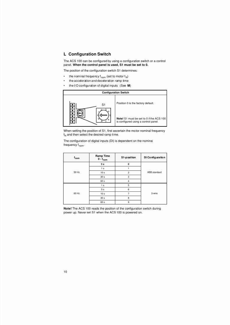
L Configuration Switch
The ACS 100 can be configured by using a configuration switch or a control
panel. When the control panel is used, S1 must be set to 0.
The position of the configuration switch S1 determines:
• the nominal frequency fnom (set to motor fN)
• the acceleration and deceleration ramp time
• the I/O configuration of digital inputs (See M)
When setting the position of S1, first ascertain the motor nominal frequency
fN and then select the desired ramp time.
The configuration of digital inputs (DI) is dependent on the nominal
frequency fnom.
Note! The ACS 100 reads the position of the configuration switch during
power up. Never set S1 when the ACS 100 is powered on.
Configuration Switch
Position 0 is the factory default.
Note! S1 must be set to 0 if the ACS 100is configured using a control panel.
fnomRamp Time
0 - fnomS1-posit ion DI Configuration
50 Hz
5 s 0
ABB standard
1 s 1
10 s 2
30 s 3
60 s 4
60 Hz
1 s 5
3-wire
5 s 6
10 s 7
30 s 8
60 s 9
0
1
2 3
4
5
69
78
S1
8/10/2019 ACS100 Manual Eng
http://slidepdf.com/reader/full/acs100-manual-eng 19/52
11
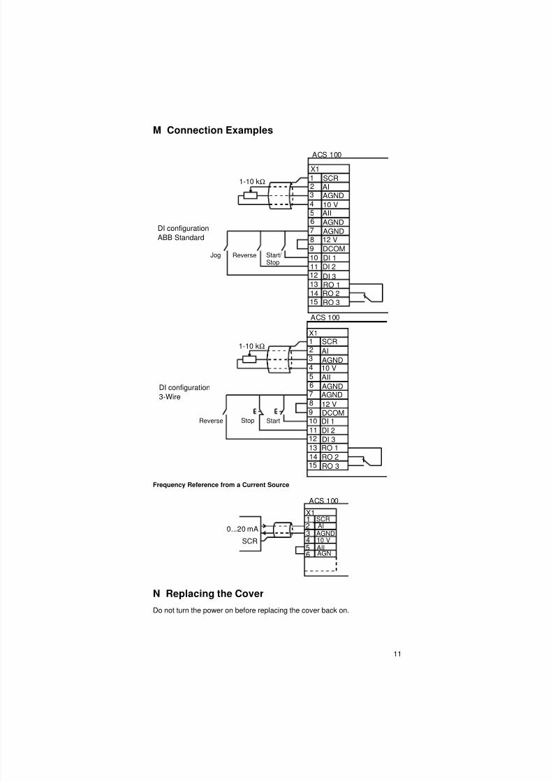
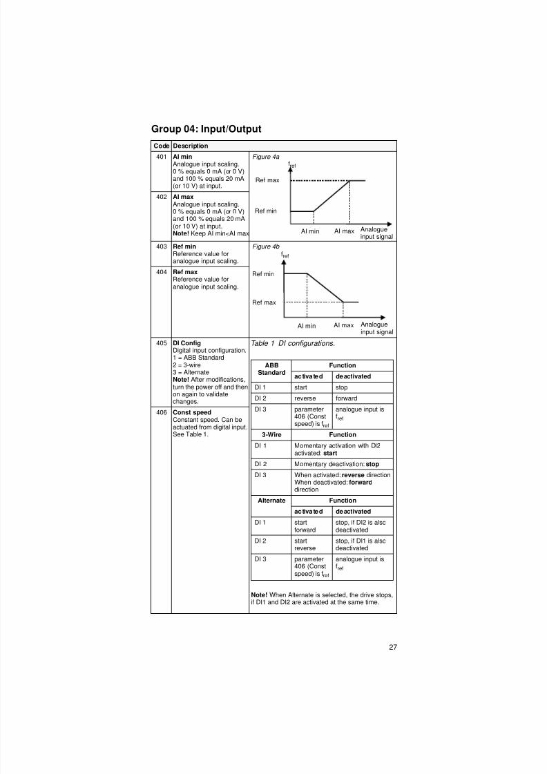
M Connection Examples
Frequency Reference from a Current Source
N Replacing the Cover
Do not turn the power on before replacing the cover back on.
DI configuration
ABB Standard
DI configuration
3-Wire
Jog
Reverse
Reverse Start/ Stop
Stop Start
ACS 100
ACS 100
X1
SCRAIAGND
10 VAII
AGND
AGND12 V
DCOM
DI 1DI 2
DI 3RO 1RO 2
RO 3
X1SCR
AI
AGND10 V
AII
AGNDAGND
12 V
DCOMDI 1
DI 2
DI 3RO 1
RO 2
RO 3
123
4
56
7
8
9
10
11
1213
1415
123
4
56
7
8
910
1112
13
1415
1-10 kΩ
1-10 kΩ
ACS 100
X11234
5
0...20 mA
SCR
6
SCRAIAGND10 V
AIIAGN
8/10/2019 ACS100 Manual Eng
http://slidepdf.com/reader/full/acs100-manual-eng 20/52
12
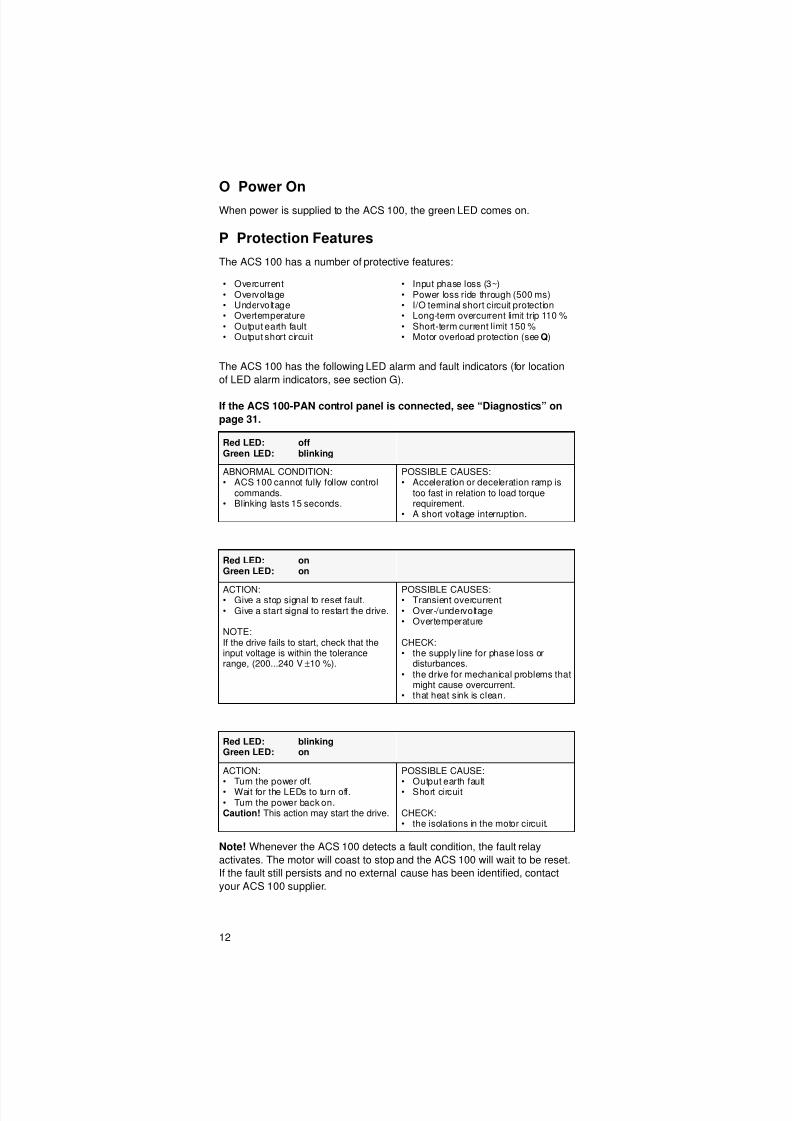
O Power On
When power is supplied to the ACS 100, the green LED comes on.
P Protection Features
The ACS 100 has a number of protective features:
The ACS 100 has the following LED alarm and fault indicators (for location
of LED alarm indicators, see section G).
If the ACS 100-PAN control panel is connected, see “Diagnostics” on
page 31.
Note! Whenever the ACS 100 detects a fault condition, the fault relay
activates. The motor will coast to stop and the ACS 100 will wait to be reset.
If the fault still persists and no external cause has been identified, contact
your ACS 100 supplier.
• Overcurrent• Overvoltage• Undervoltage• Overtemperature• Output earth fault• Output short circuit
• Input phase loss (3~)• Power loss ride through (500 ms)• I/O terminal short circuit protection• Long-term overcurrent limit trip 110 %• Short-term current limit 150 %• Motor overload protection (see Q)
Red LED: offGreen LED: blinking
ABNORMAL CONDITION:• ACS 100 cannot fully follow control
commands.• Blinking lasts 15 seconds.
POSSIBLE CAUSES:• Acceleration or deceleration ramp is
too fast in relation to load torquerequirement.
• A short voltage interruption.
Red LED: onGreen LED: on
ACTION:• Give a stop signal to reset fault.• Give a start signal to restart the drive.
NOTE:If the drive fails to start, check that theinput voltage is within the tolerancerange, (200...240 V ±10 %).
POSSIBLE CAUSES:• Transient overcurrent• Over-/undervoltage• Overtemperature
CHECK:• the supply line for phase loss or
disturbances.• the drive for mechanical problems that
might cause overcurrent.• that heat sink is clean.
Red LED: blinkingGreen LED: on
ACTION:
• Turn the power off.• Wait for the LEDs to turn off.• Turn the power back on.Caution! This action may start the drive.
POSSIBLE CAUSE:
• Output earth fault• Short circuit
CHECK:• the isolations in the motor circuit.

8/10/2019 ACS100 Manual Eng
http://slidepdf.com/reader/full/acs100-manual-eng 21/52
13
Q Motor Overload Protection
If the motor current Iout exceeds the nominal current Inom of the motor
(parameter 203) for a prolonged period of time, the ACS 100 automatically
protects the motor from overheating by tripping.
Trip time depends on the extent of the overload (Iout / Inom), the output
frequency and nominal motor frequency fnom. Times given apply to a “cold
start”.
ACS 100 provides overload protection in accordance with the National
Electric Code (US). The default setting of motor thermal protection is ON.
For more information, see parameter 502 on page 28.
R Loadability of ACS 100
In the event of an output overload, the ACS 100 will trip.
Iout / Inom
Output frequency (fnom = 50 Hz)
Output frequency (fnom = 60 Hz)
Trip time
0.5
1.5
1.0
0.0
0 H z
0 H z
4 2 H z 3 5 H z
300 s180 s
600 s
∞
Imax / I2
duty cycle
Ambient temperature,
Θamb max. is 40 °C.
50 °C is permissible,
if I2 is derated to 80 %.
Iout
time
duty cycle = t/T
T< 10 min
I2
t
1.5
1.4
1.3
1.2
1.1
1.0
0.1 0.2 0.3 0.4 0.5
Imax
T
8/10/2019 ACS100 Manual Eng
http://slidepdf.com/reader/full/acs100-manual-eng 22/52
14
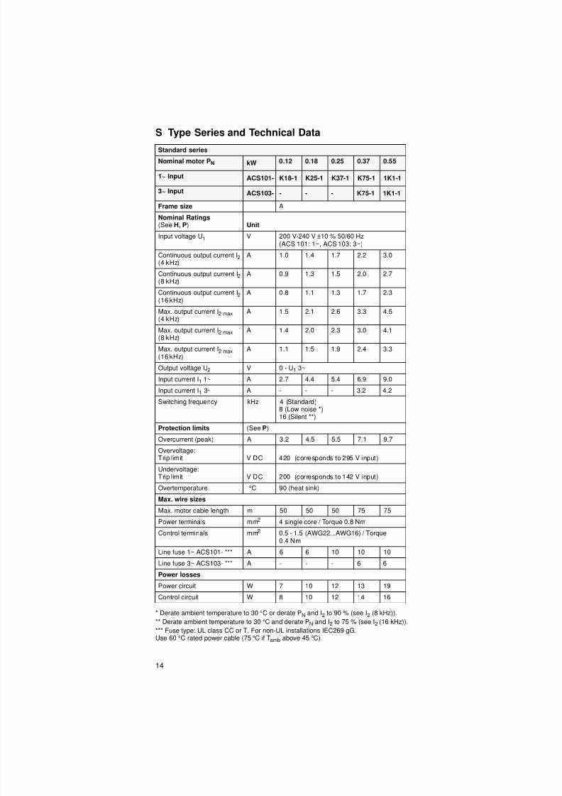
S Type Series and Technical Data
* Derate ambient temperature to 30 °C or derate PN and I2 to 90 % (see I2 (8 kHz)).
** Derate ambient temperature to 30 °C and derate PN and I2 to 75 % (see I2 (16 kHz)).
*** Fuse type: UL class CC or T. For non-UL installations IEC269 gG.Use 60 °C rated power cable (75 °C if Tamb above 45 °C).
Standard series
Nominal motor PN kW 0.12 0.18 0.25 0.37 0.55
1~ Input ACS101- K18-1 K25-1 K37-1 K75-1 1K1-1
3~ Input ACS103- - - - K75-1 1K1-1
Frame size A
Nominal Ratings(See H, P) Unit
Input voltage U1 V 200 V-240 V ±10 % 50/60 Hz(ACS 101: 1~, ACS 103: 3~)
Continuous output current I2 (4 kHz)
A 1.0 1.4 1.7 2.2 3.0
Continuous output current I2(8 kHz)
A 0.9 1.3 1.5 2.0 2.7
Continuous output current I2(16 kHz)
A 0.8 1.1 1.3 1.7 2.3
Max. output current I2 max(4 kHz)
A 1.5 2.1 2.6 3.3 4.5
Max. output current I2 max(8 kHz)
A 1.4 2.0 2.3 3.0 4.1
Max. output current I2 max (16 kHz)
A 1.1 1.5 1.9 2.4 3.3
Output voltage U2 V 0 - U1 3~
Input current I1 1~ A 2.7 4.4 5.4 6.9 9.0
Input current I1 3~ A - - - 3.2 4.2
Switching frequency kHz 4 (Standard)8 (Low noise *)
16 (Silent **)Protection limits (See P)
Overcurrent (peak) A 3.2 4.5 5.5 7.1 9.7
Overvoltage:Trip l imit V DC 420 (corresponds to 295 V input)
Undervoltage:Trip l imit V DC 200 (corresponds to 142 V input)
Overtemperature °C 90 (heat sink)
Max. wire sizes
Max. motor cable length m 50 50 50 75 75
Power terminals mm2 4 single core / Torque 0.8 Nm
Control terminals mm2 0.5 - 1.5 (AWG22...AWG16) / Torque0.4 Nm
Line fuse 1~ ACS101- *** A 6 6 10 10 10
Line fuse 3~ ACS103- *** A - - - 6 6
Power losses
Power circuit W 7 10 12 13 19
Control circuit W 8 10 12 14 16

8/10/2019 ACS100 Manual Eng
http://slidepdf.com/reader/full/acs100-manual-eng 23/52
15
* Derate ambient temperature to 30 °C or derate PN and I2 to 90 % (see I2 (8 kHz)).
** Derate ambient temperature to 30 °C and derate PN and I2 to 75 % (see I2 (16 kHz)).
*** Fuse type: UL class CC or T. For non-UL installations IEC269 gG.Use 60 °C rated power cable (75 °C if Tamb above 45 °C).
Standard series
Nominal motor PN kW 0.75 1.1 1.5 2.2
1~ Input ACS101- 1K6-1 2K1-1 2K7-1 4K1-1
3~ Input ACS103- 1K6-1 2K1-1 2K7-1 4K1-1
Frame size B C D
Nominal Ratings(See H, P) Unit
Input voltage U1 V 200 V-240 V ±10 % 50/60 Hz(ACS 101: 1~, ACS 103: 3~)
Continuous output current I2 (4 kHz)
A 4.3 5.9 7.0 9.0
Continuous output current I2
(8 kHz)
A 3.9 5.3 6.3 8.1
Continuous output current I2 (16 kHz)
A 3.2 4.4 5.3 6.8
Max. output current I2 max (4 kHz) A 6.5 8.9 10.5 13.5
Max. output current I2 max (8 kHz) A 5.9 8.0 9.5 12.2
Max. output current I2 max (16 kHz) A 4.7 6.5 7.7 9.9
Output voltage U2 V 0 - U1 3~
Input current I1 1~ A 10.8 14.8 18.2 22.0
Input current I1 3~ A 5.3 7.2 8.9 12.0
Switching frequency kHz 4 (Standard)8 (Low noise *)16 (Silent **)
Protection limits (See P)
Overcurrent (peak) A 13.8 19.0 23.5 34.5
Overvoltage:Trip l imit V DC 420 (corresponds to 295 V input)
Undervoltage:Trip limit V DC 200 (corresponds to 142 V input)
Overtemperature °C 90(heatsink)
95(heat sink)
Max. wire sizes
Max. motor cable length m 75 75 75 75
Power terminals mm2 4 single core / Torque 0.8 Nm
Control terminals mm2 0.5 - 1.5 (AWG22...AWG16) / Torque0.4 Nm
Line fuse 1~ACS101- ***
A 16 16 20 25
Line fuse 3~ACS103- ***
A 6 10 10 16
Power losses
Power circuit W 27 39 48 70
Control circuit W 17 18 19 20
8/10/2019 ACS100 Manual Eng
http://slidepdf.com/reader/full/acs100-manual-eng 24/52
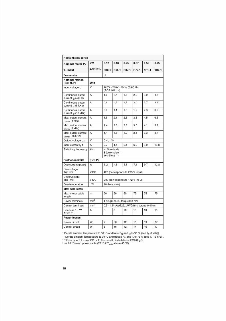
16
* Derate ambient temperature to 30 °C or derate PN and I2 to 90 % (see I2 (8 kHz)).
** Derate ambient temperature to 30 °C and derate PN and I2 to 75 % (see I2 (16 kHz)).
*** Fuse type: UL class CC or T. For non-UL installations IEC269 gG.Use 60 °C rated power cable (75 °C if Tamb above 45 °C).
Heatsinkless series
Nominal motor PNkW 0.12 0.18 0.25 0.37 0.55 0.75
1~ Input ACS101- H18-1 H25-1 H37-1 H75-1 1H1-1 1H6-1
Frame size H
Nominal ratings(See H, P) Unit
Input voltage U1 V 200V - 240V ±10 % 50/60 Hz(ACS 101:1~)
Continuous outputcurrent I2 (4 kHz)
A 1.0 1.4 1.7 2.2 3.0 4.3
Continuous outputcurrent I2 (8 kHz)
A 0.9 1.3 1.5 2.0 2.7 3.9
Continuous output
current I2 (16 kHz)
A 0.8 1.1 1.3 1.7 2.3 3.2
Max. output currentI2 max (4 kHz)
A 1.5 2.1 2.6 3.3 4.5 6.5
Max. output currentI2 max (8 kHz)
A 1.4 2.0 2.3 3.0 4.1 5.9
Max. output currentI2 max (16 kHz)
A 1.1 1.5 1.9 2.4 3.3 4.7
Output voltage U2 V 0 - U1 3~
Input current I1 1~ A 2.7 4.4 5.4 6.9 9.0 10.8
Switching frequency kHz 4 (Standard)8 (Low noise *)16 (Silent **)
Protection limits (See P)
Overcurrent (peak) A 3.2 4.5 5.5 7.1 9.7 13.8
Overvoltage:Trip limit V DC 420 (corresponds to 295 V input)
Undervoltage:Tr ip l imit V DC 200 (corresponds to 142 V input)
Overtemperature °C 90 (heat sink)
Max. wire sizes
Max. motor cablelength
m 50 50 50 75 75 75
Power terminals mm2 4 single core / torque 0.8 Nm
Control terminals mm2 0.5 - 1.5 (AWG22...AWG16) / torque 0.4 Nm
Line fuse 1~ ***ACS101-
A 6 6 10 10 10 16
Power losses
Power circuit W 7 10 12 13 19 27
Control circuit W 8 10 12 14 16 17
8/10/2019 ACS100 Manual Eng
http://slidepdf.com/reader/full/acs100-manual-eng 25/52
17
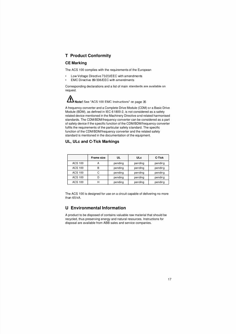
T Product Conformity
CE Marking
The ACS 100 complies with the requirements of the European
• Low Voltage Directive 73/23/EEC with amendments
• EMC Directive 89/336/EEC with amendments
Corresponding declarations and a list of main standards are available on
request.
Note! See "ACS 100 EMC Instructions" on page 35
A frequency converter and a Complete Drive Module (CDM) or a Basic Drive
Module (BDM), as defined in IEC 61800-2, is not considered as a safety
related device mentioned in the Machinery Directive and related harmonisedstandards. The CDM/BDM/frequency converter can be considered as a part
of safety device if the specific function of the CDM/BDM/frequency converter
fulfils the requirements of the particular safety standard. The specific
function of the CDM/BDM/frequency converter and the related safety
standard is mentioned in the documentation of the equipment.
UL, ULc and C-Tick Markings
The ACS 100 is designed for use on a circuit capable of delivering no more
than 65 kA.
U Environmental Information
A product to be disposed of contains valuable raw material that should be
recycled, thus preserving energy and natural resources. Instructions for
disposal are available from ABB sales and service companies.
Frame size UL ULc C-Tick
ACS 100 A pending pending pending
ACS 100 B pending pending pending
ACS 100 C pending pending pending
ACS 100 D pending pending pending
ACS 100 H pending pending pending
8/10/2019 ACS100 Manual Eng
http://slidepdf.com/reader/full/acs100-manual-eng 26/52
18
V Accessories
PEC-98-0008
Panel Extension Cable kit for use with the ACS 100 / ACS 140 / ACS 400.
ACS 100/140-IFxx-1, ACS 100-FLT-
RFI input filters.
ACS-CHK-
Input/output chokes.
ACS-BRK-
Braking units.
ACS-BRC-
Braking choppers.
8/10/2019 ACS100 Manual Eng
http://slidepdf.com/reader/full/acs100-manual-eng 27/52
19
Programming
Control Panel
This section of the manual provides information on how to use the ACS 100-
PAN control panel with an ACS 100 frequency converter.
The control panel can be connected to and detached from the converter at
any time. The panel can be used to copy parameters to other ACS 100 with
the same software revision (parameter 103).
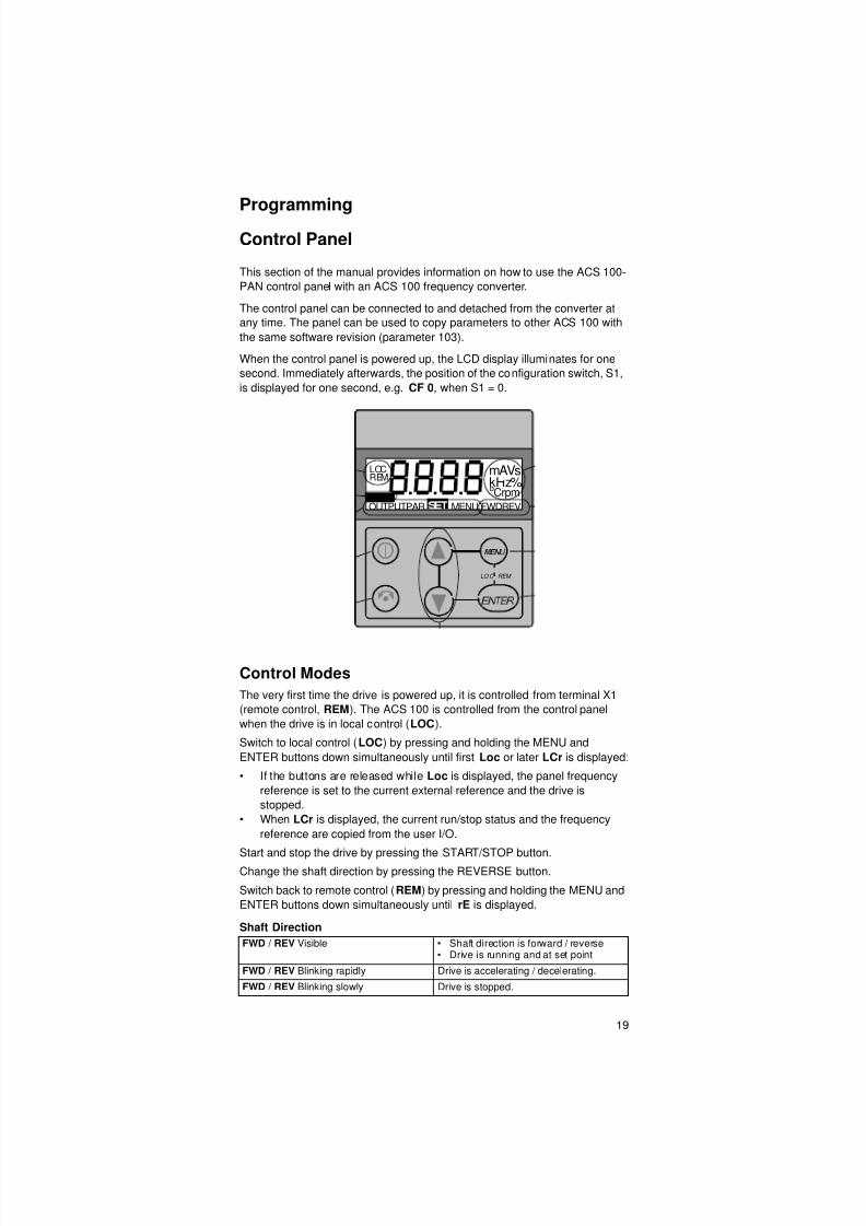
When the control panel is powered up, the LCD display illuminates for one
second. Immediately afterwards, the position of the configuration switch, S1,
is displayed for one second, e.g. CF 0, when S1 = 0.
Control Modes
The very first time the drive is powered up, it is controlled from terminal X1
(remote control, REM). The ACS 100 is controlled from the control panel
when the drive is in local control (LOC).
Switch to local control (LOC) by pressing and holding the MENU and
ENTER buttons down simultaneously until first Loc or later LCr is displayed:
• If the buttons are released while Loc is displayed, the panel frequency
reference is set to the current external reference and the drive is
stopped.
• When LCr is displayed, the current run/stop status and the frequency
reference are copied from the user I/O.
Start and stop the drive by pressing the START/STOP button.
Change the shaft direction by pressing the REVERSE button.
Switch back to remote control (REM) by pressing and holding the MENU and
ENTER buttons down simultaneously until rE is displayed.
Shaft Direction
FWD / REV Visible • Shaft direction is forward / reverse• Drive is running and at set point
FWD / REV Blinking rapidly Drive is accelerating / decelerating.
FWD / REV Blinking slowly Drive is stopped.
mAVs
OUTPUTPAR MENU FWDREV
oCrpm%REM
LOC
kHzFAULT
LO C REM
8/10/2019 ACS100 Manual Eng
http://slidepdf.com/reader/full/acs100-manual-eng 28/52
20
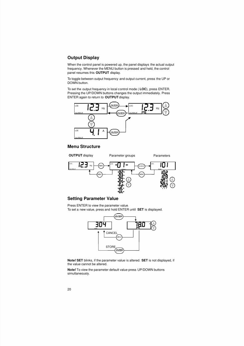
Output Display
When the control panel is powered up, the panel displays the actual output
frequency. Whenever the MENU button is pressed and held, the control
panel resumes this OUTPUT display.
To toggle between output frequency and output current, press the UP or
DOWN button.
To set the output frequency in local control mode (LOC), press ENTER.
Pressing the UP/DOWN buttons changes the output immediately. Press
ENTER again to return to OUTPUT display.
Menu Structure
Setting Parameter Value
Press ENTER to view the parameter value.
To set a new value, press and hold ENTER until SET is displayed.
Note! SET blinks, if the parameter value is altered. SET is not displayed, ifthe value cannot be altered.
Note! To view the parameter default value press UP/DOWN buttonssimultaneously.
OUTPUT
Hz
OUTPUT
Hz
OUTPUT
A
LOC
LOC
LOC
OUTPUT display Parameter groups Parameters
OUTPUT
HzLOC
LOC
MENU
LOC
PAR
PAR
s
CANCEL
STORE

8/10/2019 ACS100 Manual Eng
http://slidepdf.com/reader/full/acs100-manual-eng 29/52
8/10/2019 ACS100 Manual Eng
http://slidepdf.com/reader/full/acs100-manual-eng 30/52
22
Resetting the Drive
When the red LED of the ACS 100 is on or blinking, there is an active fault.
To reset a fault when the red LED is on, press the START/STOP button.
Caution! When in remote control, this may start the drive.
To reset a fault when the red LED is blinking, turn the power off.
Caution! Turning the power on again may start the drive immediately.
The relevant fault code (see Diagnostics) flashes in the panel display until
the fault is reset or the display is “cleared”.
You can “clear” the display without resetting the fault by pressing any button.
The word FAULT will be visible in the display.
Note! If no other button is pressed within 15 seconds and the fault is still
active, the fault code will be displayed again.
After a power failure, the drive will be in the same control mode (LOC orREM) as before the power failure.
8/10/2019 ACS100 Manual Eng
http://slidepdf.com/reader/full/acs100-manual-eng 31/52
23
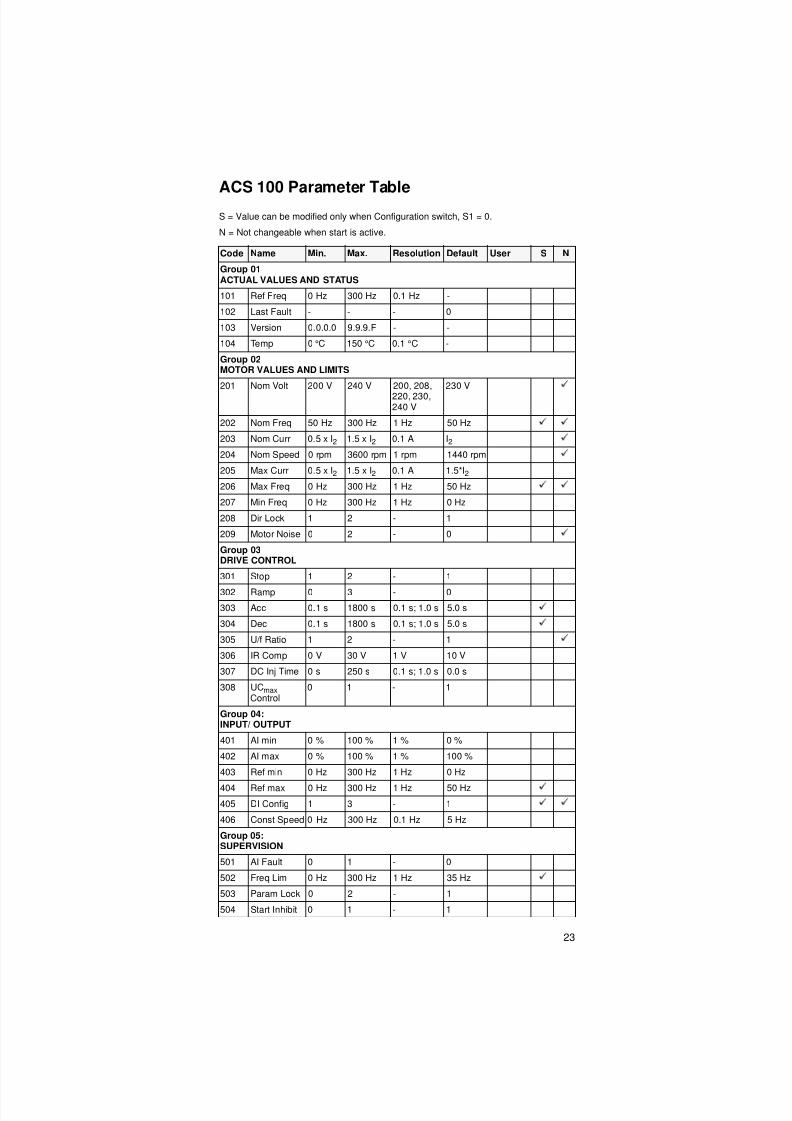
ACS 100 Parameter Table
S = Value can be modified only when Configuration switch, S1 = 0.
N = Not changeable when start is active.
Code Name Min. Max. Resolution Default User S N
Group 01ACTUAL VALUES AND STATUS
101 Ref Freq 0 Hz 300 Hz 0.1 Hz -
102 Last Fault - - - 0
103 Version 0.0.0.0 9.9.9.F - -
104 Temp 0 °C 150 °C 0.1 °C -
Group 02 MOTOR VALUES AND LIMITS
201 Nom Volt 200 V 240 V 200, 208,220, 230,240 V
230 V
202 Nom Freq 50 Hz 300 Hz 1 Hz 50 Hz
203 Nom Curr 0.5 x I2 1.5 x I2 0.1 A I2
204 Nom Speed 0 rpm 3600 rpm 1 rpm 1440 rpm
205 Max Curr 0.5 x I2 1.5 x I2 0.1 A 1.5*I2
206 Max Freq 0 Hz 300 Hz 1 Hz 50 Hz
207 Min Freq 0 Hz 300 Hz 1 Hz 0 Hz
208 Dir Lock 1 2 - 1
209 Motor Noise 0 2 - 0
Group 03DRIVE CONTROL
301 Stop 1 2 - 1
302 Ramp 0 3 - 0
303 Acc 0.1 s 1800 s 0.1 s; 1.0 s 5.0 s
304 Dec 0.1 s 1800 s 0.1 s; 1.0 s 5.0 s
305 U/f Ratio 1 2 - 1
306 IR Comp 0 V 30 V 1 V 10 V
307 DC Inj Time 0 s 250 s 0.1 s; 1.0 s 0.0 s
308 UCmax Control
0 1 - 1
Group 04:INPUT/ OUTPUT
401 AI min 0 % 100 % 1 % 0 %
402 AI max 0 % 100 % 1 % 100 %
403 Ref min 0 Hz 300 Hz 1 Hz 0 Hz
404 Ref max 0 Hz 300 Hz 1 Hz 50 Hz
405 DI Config 1 3 - 1
406 Const Speed 0 Hz 300 Hz 0.1 Hz 5 Hz
Group 05:SUPERVISION
501 AI Fault 0 1 - 0
502 Freq Lim 0 Hz 300 Hz 1 Hz 35 Hz
503 Param Lock 0 2 - 1
504 Start Inhibit 0 1 - 1

8/10/2019 ACS100 Manual Eng
http://slidepdf.com/reader/full/acs100-manual-eng 32/52
24
505 Auto Reset 0 s 3 s 0.1 s 0 s
506 DisplayAlarms
0 1 - 0
Code Name Min. Max. Resolution Default User S N
8/10/2019 ACS100 Manual Eng
http://slidepdf.com/reader/full/acs100-manual-eng 33/52
25
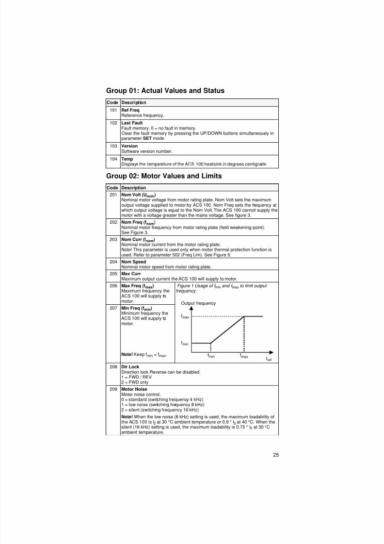
Group 01: Actual Values and Status
Group 02: Motor Values and Limits
Code Description
101 Ref FreqReference frequency.
102 Last FaultFault memory. 0 = no fault in memory.Clear the fault memory by pressing the UP/DOWN buttons simultaneously inparameter SET mode.
103 VersionSoftware version number.
104 TempDisplays the temperature of the ACS 100 heatsink in degrees centigrade.
Code Description
201 Nom Volt (Unom)Nominal motor voltage from motor rating plate. Nom Volt sets the maximumoutput voltage supplied to motor by ACS 100. Nom Freq sets the frequency atwhich output voltage is equal to the Nom Volt. The ACS 100 cannot supply themotor with a voltage greater than the mains voltage. See figure 3.
202 Nom Freq (fnom)Nominal motor frequency from motor rating plate (field weakening point).See Figure 3.
203 Nom Curr (Inom)Nominal motor current from the motor rating plate.Note! This parameter is used only when motor thermal protection function isused. Refer to parameter 502 (Freq Lim). See Figure 5.
204 Nom SpeedNominal motor speed from motor rating plate.
205 Max CurrMaximum output current the ACS 100 will supply to motor.
206 Max Freq (fmax)Maximum frequency theACS 100 will supply tomotor.
Figure 1 Usage of f min and f max to limit outputfrequency.
207 Min Freq (fmin)Minimum frequency theACS 100 will supply tomotor.
Note! Keep fmin < fmax.
208 Dir LockDirection lock Reverse can be disabled.1 = FWD / REV
2 = FWD only
209 Motor NoiseMotor noise control.0 = standard (switching frequency 4 kHz)1 = low noise (switching frequency 8 kHz)2 = silent (switching frequency 16 kHz)
Note! When the low noise (8 kHz) setting is used, the maximum loadability ofthe ACS 100 is I2 at 30 °C ambient temperature or 0.9 * I2 at 40 °C. When thesilent (16 kHz) setting is used, the maximum loadability is 0.75 * I2 at 30 °Cambient temperature.
Output frequency
fmax
fmin
fmaxfminfref

8/10/2019 ACS100 Manual Eng
http://slidepdf.com/reader/full/acs100-manual-eng 34/52
26
Group 03: Drive Control
Code Description
301 StopStop mode.1 = Coast2 = RampSee also parameter 307 (DC Inj. Time).
302 RampRamp shape.0 = Linear1 = Fast S curve2 = Medium S curve3 = Slow S curve
Figure 2
303 AccAcceleration time from zero to maximum frequency (0 - fmax).
304 DecDeceleration time from maximum frequency to zero (fmax - 0).
305 U/f RatioU/f below weakening point.1 = Linear (curves A andC)2 = Square (curves B andD)Linear is preferred forconstant torqueapplications and Squarefor centrifugal pump and
fan applications.
Figure 3
306 IR CompAmount of IRcompensation, i.e. extravoltage applied to motor onfrequency range 0 - fnom.Note! IR compensationshould be kept as low aspossible.
307 DC Inj TimeDC injection time after modulation has stopped. If stop mode is Coast, ACS 100uses DC Braking. If stop mode is Ramp, ACS 100 uses DC Hold after ramp.
308 UCmaxOvervoltage regulator control.Should be 0, if braking chopper is connected.0 = No overvoltage control1 = Overvoltage control enabled
Time
Output frequency
fmax
Acc
S-curve
Linear
Output voltage
IR comp
fnom
0 V
Unom
30 V
D
CB
A
8/10/2019 ACS100 Manual Eng
http://slidepdf.com/reader/full/acs100-manual-eng 35/52

8/10/2019 ACS100 Manual Eng
http://slidepdf.com/reader/full/acs100-manual-eng 36/52
28
Group 05: Supervision
Code Description
501 AI FaultAnalogue input supervision.0 = not in use1 = If analogue input is below the level given by parameter 401 (AI min), a faultindication is displayed and the ACS 100 coasts to stop.
502 Freq Lim (flim)Frequency limit for thermalprotection. Together withparameter 203 (Nom Curr)determines the continuoussafe operation area for themotor.
0 Hz = Thermal protectiondisabled.
Figure 5
503 Param LockParameter lock.0 = STAR/STOP and REVERSE buttons and parameter modification disabled.
Parameter value viewing is allowed.1 = Not locked.2 = Modified values not stored in permanent memory.
504 Start InhibitStart inhibit control. Start inhibit means that a pending start command is ignoredwhen:
• fault is reset, or• mode change from local to remote takes place.
0 = OffStart inhibit control disabled. Drive will start after fault is reset or mode ischanged while there is a pending start command.1 = OnStart inhibit control is enabled. Drive will not start after fault is reset or mode ischanged. In order to start the drive again, give start command anew.
505 Auto ResetThe automatic reset system can be used for resetting undervoltage faultsautomatically.Auto reset sets the number of allowed auto resets (5) within a certain time(30 s).0 s = Disable
If a value greater than 0 s is selected, the undervoltage fault is resetautomatically after the delay set by this parameter. If 0 s is selected, the fault isnot reset automatically.
Figure 6 Operation of automatic reset function. The number of trials is constant5 and the trial time is constant 30 s. By moment ‘Now’ three faults has occurredmaking the next fault fourth, the system is reset automatically because thenumber of trials is less than 5.
Iout /Inom
fout /flim
3.0
2.5
2.0
1.5
1.0
0.5
0.2 0.4 0.6 0.8 1.00.00.0
Trip time
60 s
90 s
180 s
300 s
∞
X X X Time
Trial time
x = Automatic resetNow

8/10/2019 ACS100 Manual Eng
http://slidepdf.com/reader/full/acs100-manual-eng 37/52
29
506 Display Alarms
Controls the visibility of some of the alarms, see "Diagnostics" on page 31.0 = NoSome of the alarms are suppressed.1 = YesAll of the alarms are enabled.

8/10/2019 ACS100 Manual Eng
http://slidepdf.com/reader/full/acs100-manual-eng 38/52
8/10/2019 ACS100 Manual Eng
http://slidepdf.com/reader/full/acs100-manual-eng 39/52
31
Diagnostics
General
This chapter describes the various diagnostic displays of the control panel
and lists the most common causes for the particular display. If the fault
cannot be resolved by the given instructions, contact an ABB service
representative.
Caution! Do not attempt any measurement, parts replacement or other
service procedures not described in this manual. Such actions will void
guarantee, endanger correct operation, and increase downtime and
expense.
Alarm and Fault displays
The seven-segment display unit of control panel indicates a larms and faults
using codes “ALxx” or “FLxx”, where xx is the corresponding alarm or fault
code.
Alarms 1-6 arise from button operation. Green LED blinks for AL10-16,
meaning that the ACS 100 cannot fully follow the control commands. The
faults are indicated by red LED.
The alarm and fault messages disappear by pressing MENU, ENTER or the
arrow buttons of the control panel. The message will reappear after a few
seconds if the keypad is not touched and the alarm or fault is still active.
Last fault code is stored into parameter 102. This fault memory can be
cleared from the control panel by pressing UP and DOWN buttons
simultaneously in parameter set mode.
Fault ResettingFaults that are indicated by a red blinking LED are reset by turning the power
off for a while. Other faults (indicated by red static LED) can be reset either
from the control panel, by digital input or serial communication, or switching
the supply voltage off for a while. When the fault has been removed, the
motor can be started.
The ACS 100 can be configured to automatically reset certain faults. Refer
to parameter 505 AUTO RESET.
Warning! If an external source for start command is selected and is still
active, the ACS 100 may start immediately after fault reset.
Warning! All electrical installation and maintenance work described in this
chapter should only be undertaken by a qualified electrician. The SafetyInstructions on the first pages of this manual must be followed.

8/10/2019 ACS100 Manual Eng
http://slidepdf.com/reader/full/acs100-manual-eng 40/52

8/10/2019 ACS100 Manual Eng
http://slidepdf.com/reader/full/acs100-manual-eng 41/52
33
Table 3 Faults
Note! Faults (*) with red blinking LED are reset by turning the power off and
on. Other faults are reset by pressing the START/STOP button.
Code Description
FL 1 Overcurrent:• Possible mechanical problem.• Acc and/or Dec times may be too small.
FL 2 DC overvoltage:• Input voltage too high.• Dec time may be too small.
FL 3 ACS 100 overtemperature:• Ambient temperature too high.• Severe overload.
FL 4 * Fault current: output earth fault or short ci rcui t.
FL 5 Output overload.
FL 6 DC undervoltage.
FL 7 Analogue input fault. (See parameter 501.)
FL 8 Motor overtemperature. (See parameter 502.)
FL 9 Panel disconnected from drive in local control.Note! If FL 9 is active when the power is turned off, the ACS 100 willstart in remote control (REM) when the power is turned back on.
FL10 Parameters inconsistent.Check that AI min (fmin) is not greater than AI max (fmax).
FL11 * DC bus ripple too large.Check supply.
FL12 Reserved. Contact supplier.
FL13 - FL14* Hardware error. Contact supplier.
FL15* Analogue input out of range. Check AI level .
FL16-FL19* Hardware error. Contact supplier.
Full displayblinking
Serial link failure.Bad connection between the control panel and the ACS 100.

8/10/2019 ACS100 Manual Eng
http://slidepdf.com/reader/full/acs100-manual-eng 42/52
34
8/10/2019 ACS100 Manual Eng
http://slidepdf.com/reader/full/acs100-manual-eng 43/52

8/10/2019 ACS100 Manual Eng
http://slidepdf.com/reader/full/acs100-manual-eng 44/52
36
Cabling Instructions
Keep individual unscreened wires between the cable clamps and the screw
terminals as short as possible. Route control cables away from power
cables.
Mains Cable
A three conductor cable (single phase and neutral with protective earth) or
four conductor cable (three phase with protective earth) are recommended
for the mains cabling. Shielding is not necessary. Dimension the cables and
fuses in accordance with the input current. Always pay attention to local
legislation when sizing the cables and fuses.
The mains input connectors are at the top of the converter unit. Mains cable
routing must be done so that the distance from the sides of the converter is
at least 20 cm to avoid excessive radiation to the mains cable. In the case of
screened cable twist the cable screen wires together into a bundle not longer
than five times its width and connect to the PE terminal of the converter. (Or
PE terminal of input filter, if present.)
Motor Cable
The motor cable must be a symmetrical three conductor cable with a
concentric PE conductor or a four conductor cable with a concentric shield.
Minimum requirement for the motor cable screen is presented in Figure 7.
Figure 7 Minimum requirement for motor cable screen (e.g. MCMK, NK
Cables).
The general rule for cable screen effectiveness is: the better and tighter the
screen of the cable, the lower the radiated emission level. Example of an
effective construction is presented in Figure 8.
Figure 8 Effective motor cable screen (e.g. Ölflex-Servo-FD 780 CP,Lappkabel or MCCMK, NK Cables).
Twist the cable screen wires together into a bundle not longer than five times
its width and connect to the bottom left-hand corner of the converter heatsink
(terminal marked ).
L2L1
L3
PE, optional
Helix of copper tapeInner insulator
Copper wire screen
Insulation jacket
Insulation jacketBraided metallic screen Inner insulator
L2L1
PE, optional
L3
8/10/2019 ACS100 Manual Eng
http://slidepdf.com/reader/full/acs100-manual-eng 45/52
37
At the motor end the motor cable screen must be earthed 360 degrees with
an EMC cable gland (e.g. ZEMREX SCG Screened cable glands) or thescreen wires must be twisted together into a bundle not longer than five
times its width and connected to the PE terminal of the motor.
Control Cables
Control cables must be multi-core cables with a braided copper wire screen.
The screen must be twisted together into a bundle not longer than five times
its width and connected to terminal X1:1.
Route the control cables as far away as possib le from the mains and motor
cables (at least 20 cm). Where control cables must cross power cables
make sure they are at an angle as near 90 degrees as possible. Also the
cable routing must be done so that the distance from the sides of the
converter is at least 20 cm to avoid excessive radiation to the cable.
A double shielded twisted pair cable is recommended for the analogue
signals. Employ one individually shielded pair for each signal. Do not use
common return for different analogue signals.
A double shielded cable is the best alternative for low voltage digital signals
but single shielded twisted multipair cable is also usable (see Figure 9).
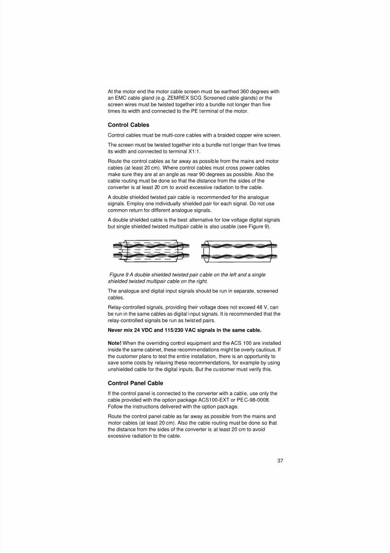
Figure 9 A double shielded twisted pair cable on the left and a single
shielded twisted multipair cable on the right.
The analogue and digital input signals should be run in separate, screenedcables.
Relay-controlled signals, providing their voltage does not exceed 48 V, can
be run in the same cables as digital input signals. It is recommended that the
relay-controlled signals be run as twisted pairs.
Never mix 24 VDC and 115/230 VAC signals in the same cable.
Note! When the overriding control equipment and the ACS 100 are installed
inside the same cabinet, these recommendations might be overly cautious. If
the customer plans to test the entire installation, there is an opportunity to
save some costs by relaxing these recommendations, for example by using
unshielded cable for the digital inputs. But the customer must verify this.
Control Panel Cable
If the control panel is connected to the converter with a cable, use only the
cable provided with the option package ACS100-EXT or PEC-98-0008.
Follow the instructions delivered with the option package.
Route the control panel cable as far away as possible from the mains and
motor cables (at least 20 cm). Also the cable routing must be done so that
the distance from the sides of the converter is at least 20 cm to avoid
excessive radiation to the cable.
8/10/2019 ACS100 Manual Eng
http://slidepdf.com/reader/full/acs100-manual-eng 46/52
38
Additional Instructions to Comply with EN61800-3,First Environment, Restricted Distribution, and AS/NZS 2064, 1997, Class A
Always use optional RFI filter as specified in Tables 4 and 5 and follow the
instructions in the filter package for all cable screen connections.
The filters with regular cable lengths are shown in Table 4 and the filters with
extra long cable lengths in Table 5.
The motor cable lengths have to be limited as specified in Tables 4 and 5. At
the motor end, the cable screen must be earthed 360 degrees with an EMC
cable gland (e.g. Zemrex SCG screened cable glands).
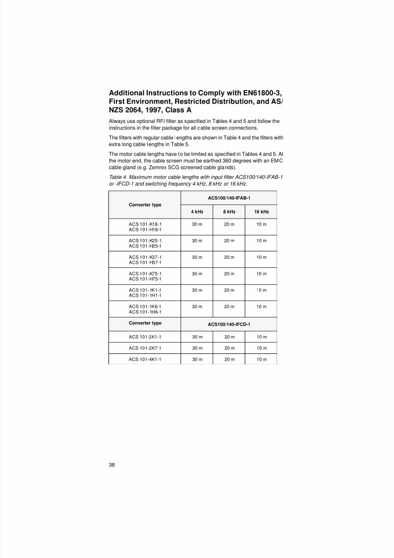
Table 4 Maximum motor cable lengths with input filter ACS100/140-IFAB-1
or -IFCD-1 and switching frequency 4 kHz, 8 kHz or 16 kHz.
Converter type
ACS100/140-IFAB-1
4 kHz 8 kHz 16 kHz
ACS 101-K18-1ACS 101-H18-1
30 m 20 m 10 m
ACS 101-K25-1ACS 101-H25-1
30 m 20 m 10 m
ACS 101-K37-1ACS 101-H37-1
30 m 20 m 10 m
ACS 101-K75-1ACS 101-H75-1
30 m 20 m 10 m
ACS 101-1K1-1ACS 101-1H1-1
30 m 20 m 10 m
ACS 101-1K6-1ACS 101-1H6-1
30 m 20 m 10 m
Converter type ACS100/140-IFCD-1
ACS 101-2K1-1 30 m 20 m 10 m
ACS 101-2K7-1 30 m 20 m 10 m
ACS 101-4K1-1 30 m 20 m 10 m

8/10/2019 ACS100 Manual Eng
http://slidepdf.com/reader/full/acs100-manual-eng 47/52
39
Table 5 Maximum motor cable lengths with input filter ACS100-FLT-C or
ACS 140- FLT-C and switching frequency 4 kHz or 8 kHz.
* Effective motor cable screen is required, according to Figure 8.**ACS 103-4K1-1: maximum continuous load 70 % of nominal.For ACS 101-4K1-1 and ACS 103-4K1-1, a cable shown in Figure 8 is required.
Always use output choke ACS-CHK-B, if motor cable length exceeds 50 m.
With input filter ACS100-FLT-C always use ouput choke ACS-CHK-A.
Chokes ACS-CHK-A and ACS-CHK-B are supplied in the same package
with the input filter ACS100-FLT-C.
With input fi lters ACS100-FLT-C or ACS140-FLT-C conducted emission
complies with the limits for unrestricted distribution class in FirstEnvironment as specified in EN 61800-3 (EN 50081-1) provided that the
motor cable has effective screen (see Figure 8) and maximum length is
30 m.
Converter Type
ACS100-FLT-C
4 kHz 8 kHz*
ACS 101-K75-1 100 m 100 m
ACS 101-1K1-1 100 m 100 m
ACS 101-1K6-1 100 m 100 m
ACS 101-2K-1 100 m 100 m
ACS 101-2K7-1 100 m 100 m
ACS 101-4K1-1 100 m 100 m
Converter Type ACS140-FLT-C
ACS 103-xKx-1** 100 m 100 m
8/10/2019 ACS100 Manual Eng
http://slidepdf.com/reader/full/acs100-manual-eng 48/52
40
Additional Instructions to Comply with EN61800-3,First Environment, Unrestricted Distribution
Always use optional RFI filter ACS100-FLT-D or ACS100-FLT-E and follow
the instructions in the filter package for all cable screen connections.
The motor cable lengths have to be limited as specified in Table 6 and the
cable must have effective screen according to Figure 8. At the motor end,
the cable screen must be earthed 360 degrees with an EMC cable gland
(e.g. Zemrex SCG screened cable glands).
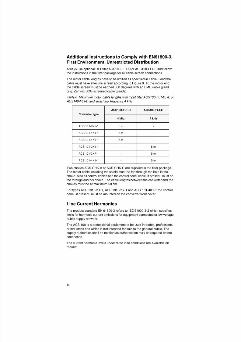
Table 6 Maximum motor cable lengths with input filter ACS100-FLT-D, -E or
ACS140-FLT-D and switching frequency 4 kHz.
Two chokes ACS-CHK-A or ACS-CHK-C are supplied in the filter package.
The motor cable including the shield must be fed through the hole in the
choke. Also all control cables and the control panel cable, if present, must be
fed through another choke. The cable lengths between the converter and thechokes must be at maximum 50 cm.
For types ACS 101-2K1-1, ACS 101-2K7-1 and ACS 101-4K1-1 the control
panel, if present, must be mounted on the converter front cover.
Line Current Harmonics
The product standard EN 61800-3 refers to IEC 61000-3-2 which specifies
limits for harmonic current emissions for equipment connected to low voltage
public supply network.
The ACS 100 is a professional equipment to be used in trades, professions,
or industries and which is not intended for sale to the general public. The
supply authorities shall be notified as authorisation may be required before
connection.
The current harmonic levels under rated load conditions are available on
request.
Converter type
ACS100-FLT-D ACS100-FLT-E
4 kHz 4 kHz
ACS 101-K75-1 5 m -
ACS 101-1K1-1 5 m -
ACS 101-1K6-1 5 m -
ACS 101-2K1-1 - 5 m
ACS 101-2K7-1 - 5 m
ACS 101-4K1-1 - 5 m

8/10/2019 ACS100 Manual Eng
http://slidepdf.com/reader/full/acs100-manual-eng 49/52
41
Distribution Networks Isolated from Earth
Input filters cannot be used in floating supply networks, or h igh impedance
earthed industrial distribution networks.
Make sure that no excessive emission is propagated to neighbouring low
voltage networks. In some cases, the natural suppression in transformers
and cables is sufficient. If in doubt, a supply transformer with static screening
between the primary and secondary windings can be used.

8/10/2019 ACS100 Manual Eng
http://slidepdf.com/reader/full/acs100-manual-eng 50/52
42

8/10/2019 ACS100 Manual Eng
http://slidepdf.com/reader/full/acs100-manual-eng 51/52
8/10/2019 ACS100 Manual Eng
http://slidepdf.com/reader/full/acs100-manual-eng 52/52
ABB Industry Oy
P.O. Box 184
00381 Helsinki
FINLAND
Telephone +358-10-22 2000
Telefax +358-10-22 22681
3 B F E
6 4 3 0 7 6 2 2 R 0 1 2 5
E N
E f f e c t i v e :
8 . 3 . 2
0 0 0
© 2 0
0 0 A B B I n d u s
t r y O y
S u
b j e
c t t o c
h a n g e w
i t h o u
t p r i o r n o
t i c e .