active design method for the static characteristics of a
TRANSCRIPT
Sensors 2014, 14, 659-671; doi:10.3390/s140100659
sensors ISSN 1424-8220
www.mdpi.com/journal/sensors
Article
Active Design Method for the Static Characteristics of a
Piezoelectric Six-Axis Force/Torque Sensor
Jun Liu 1,2,
*, Min Li 1,2
, Lan Qin 1,2
and Jingcheng Liu 1,2
1 Key Laboratory of Optoelectronics Technology and Systems Ministry of Education,
Chongqing University, Chongqing 400044, China; E-Mails: [email protected] (M.L.);
[email protected] (L.Q.); [email protected] (J.L.) 2
College of Optoelectronic Engineering, Chongqing University, Chongqing 400044, China
* Author to whom correspondence should be addressed; E-Mail: [email protected];
Tel.: +86-23-6511-2327; Fax: +86-23-6511-2327.
Received: 11 October 2013; in revised form: 15 December 2013 / Accepted: 23 December 2013 /
Published: 2 January 2014
Abstract: To address the bottleneck issues of an elastic-style six-axis force/torque sensor
(six-axis force sensor), this work proposes a no-elastic piezoelectric six-axis force sensor.
The operating principle of the piezoelectric six-axis force sensor is analyzed, and a
structural model is constructed. The static-active design theory of the piezoelectric six-axis
force sensor is established, including a static analytical/mathematical model and numerical
simulation model (finite element model). A piezoelectric six-axis force sensor
experimental prototype is developed according to the analytical mathematical model and
numerical simulation model, and selected static characteristic parameters (including
sensitivity, isotropic degree and cross-coupling) are tested using this model with three
approaches. The measured results are in agreement with the analytical results from the
static-active design method. Therefore, this study has successfully established a foundation
for further research into the piezoelectric multi-axis force sensor and an overall design
approach based on static characteristics.
Keywords: finite element; static characteristic; six-axis force/torque; piezoelectric sensor;
active design theory
OPEN ACCESS

Sensors 2014, 14 660
1. Introduction
A six-axis force sensor is a device designed for measuring external forces and collecting spatial
force information from three force components (Fx, Fy, Fz) and three torque components (Mx, My, Mz).
Such a device also detects the position information of the force functional point. These sensors play
significant roles in space robot design, space station docking simulations, rocket engine thrust testing,
rocket-assisted aerodynamic characteristics testing, the collection of real time center position
information for a flexible seating system, machine health monitoring and other applications. According
to the GB7665-87 national standard, the six-axis force sensor can be classified as either elastic
style [1,2] or non-elastic style [3].
Currently, three bottleneck issues exist in the elastic-style six-axis force sensor, including a degree
of structural complexity and difficulty in decoupling [4], high stiffness and high sensitivity [5] and
issues of elastic quality and degree of cross coupling [6]; these issues affect its performance, create
obstacles to further enhancement, and restrict further expansion of its application space. Therefore,
researchers have carried out studies on a non-elastic style six-axis force sensor with component forces
acting directly on the sensing elements. This sensor uses piezoelectric components as the sensing
element and conversion element, and when combined with a multi-point support structure, this device
is able to measure the six-axis forces. However, at present, few research results are available. Didler [7]
and Liu [8] developed a Stewart-structure piezoelectric six-axis force sensor that embedded quartz
crystal chips into the six legs of the Stewart platform. Li [9] researched a large-range six-axis force
sensor based on the six-axis force platform of the Kistler company. The devices in these studies are
able to overcome the bottleneck issues of the elastic-style six-axis force sensor. However, these
research programs were aimed at a specific goal, and a universal analytical/mathematical model has
yet to be developed. As a result, it is difficult to achieve miniaturization of the sensor. For this reason,
this work [3] proposes a piezoelectric six-axis force research program based on an eight-point support
structure that can deliver miniaturization [10] and enhance the dynamic performance of the sensor.
However, due to the influence of the electrode plates, the performance of this device is affected by
environmental humidity, and thus its stability must be further strengthened.
The ultimate goal for the static design of the piezoelectric six-axis force sensor is to realize an
active design based on its static performance. This effort requires research into the isotropic
characteristics that affect the measurement accuracy [11], and more importantly, it requires
comprehensive study and design of the device’s static performance. The research method uses a
high-precision analytical/mathematic model to deliver an optimal design of the piezoelectric six-axis
force sensor. Furthermore, this work uses the conclusions of the numerical simulation model to
optimize the analytical/mathematical model and verify its effectiveness and uses the experimental
results to verify the correctness of analytical model and numerical model (i.e., to build the active
design theory for these sensors). Active design theory plays an important role in the static design of a
six-axis force sensor, and the static analytical/mathematical model acts as its foundation [12].
Compared with single-axis force sensors, the six-axis force sensor’s structure is more complex, and
thus it is more difficult to deduce an effective analytical/mathematical model. Due to these difficulties,
many different types of six-axis force sensors have been proposed, but no one has been able to identify
Sensors 2014, 14 661
the in-depth design theory, and therefore, studies of the characteristics of these sensors are still carried
out solely by experimental calibration.
To meet the need for a piezoelectric six-axis force sensor active design based on its static
characteristics, this work researches the active design method of the piezoelectric six-axis force
sensor’s static characteristics based on preliminary studies. Piezoelectric quartz is selected for the force
sensing elements. The operating principle of the six-axis force sensor is analyzed, and an eight-point
support structure based on a double quartz crystal chip group is proposed. Furthermore, a static
analytical/mathematical model is built, a numerical finite element model of the piezoelectric six-axis
force sensor is set up, and the active design theory of this type of sensor is established. The correctness
of the active design theory is verified by the calibration results from the piezoelectric six-axis force
sensor experimental prototype, and the conclusions of the study reveal the main factors that affect the
six-axis force sensor’s static characteristics.
2. Measurement Principle and Structure Model
According to the structural characteristics of the piezoelectric element inside the piezoelectric force
sensor, the force sensor can be divided into two types, including the integral structure and
disaggregated structure. The integral structure piezoelectric force sensor consists of an internal
piezoelectric element in the form of a complete wafer or annular plates. The disaggregated structure of
the piezoelectric force sensor includes a number of piezoelectric elements, which are evenly arranged
according to specific rules. The integral structure can reduce the cross-sectional area of the sensor, but
its number of measurement dimensions cannot exceed four, which is not suitable for large-size
structures. Therefore, it is difficult to miniaturize this sensor using MEMS technology. Therefore,
a piezoelectric element multi-point support structure should be used if the piezoelectric elements are
expected to achieve multi-axis force measurements of more than four dimensions.
2.1. Measurement Principle
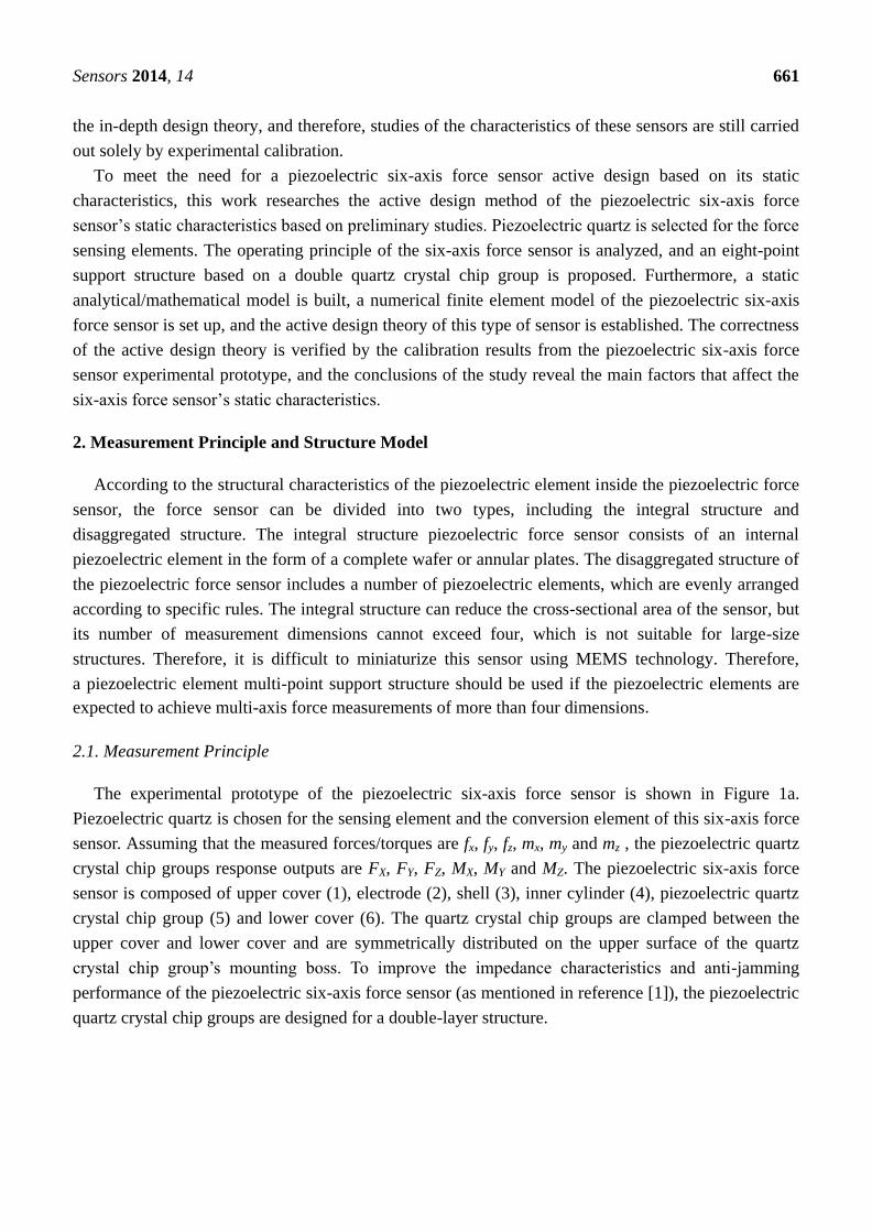
The experimental prototype of the piezoelectric six-axis force sensor is shown in Figure 1a.
Piezoelectric quartz is chosen for the sensing element and the conversion element of this six-axis force
sensor. Assuming that the measured forces/torques are fx, fy, fz, mx, my and mz , the piezoelectric quartz
crystal chip groups response outputs are FX, FY, FZ, MX, MY and MZ. The piezoelectric six-axis force
sensor is composed of upper cover (1), electrode (2), shell (3), inner cylinder (4), piezoelectric quartz
crystal chip group (5) and lower cover (6). The quartz crystal chip groups are clamped between the
upper cover and lower cover and are symmetrically distributed on the upper surface of the quartz
crystal chip group’s mounting boss. To improve the impedance characteristics and anti-jamming
performance of the piezoelectric six-axis force sensor (as mentioned in reference [1]), the piezoelectric
quartz crystal chip groups are designed for a double-layer structure.
Sensors 2014, 14 662
Figure 1. Schematic diagram of piezoelectric 6-axis force sensor. (a) Photo of a
piezoelectric six-axis force sensor. (b) Exploded view of a six-axis force sensor.
(c) Spatial layout structure schematic of quartz chip groups.
1 2 3 4 5 6
(a) (b) (c)
Figure 1b shows the structural schematic and layout of the quartz crystal chip groups within the
piezoelectric six-axis force sensor. Eight quartz crystal chip groups are evenly distributed on the same
distribution circle. Four groups of Y00-crystals are distributed on the nodes of the X and Y axes and the
quartz crystal chip groups distribution circle and are used for the measurement of , and . Four
groups of X00-crystals are distributed on the other locations and are used for the measurement of ,
and . Each group quartz crystal chip group corresponds to a one-channel output signal and can
obtain 6-channel signals via pretreatment of 8-channel signals, and the six-axis forces can be measured
via operation of a decoupling matrix. Equation (1) represents the 8-channel signal to 6-channel signal
conversion expression in which the subscript letters represent the spatial axes and the value index
indicates the number of quartz chip groups:
1 5
3 7
2 4 6 8
2 8 4 6
6 8 2 4
1 3 5 7
[( ) ( )]
[( ) ( )]
Y Y
Y Y
Z Z Z Z
Z Z Z Z
Z Z Z Z
X X X X
x
y
z
x
y
z
X f
Y f
Z f
X m
Y m
Z m
F F F
F F F
F F F F F
M F F F F
M F F F F
M F F F F
k
k
k
k
k
k
(1)
Due to the influence of the piezoelectric six-axis accelerometer structure, the layout of the quartz
chip group, the quantity and production level (among other factors), the arrangement of the quantity of
quartz crystal cells and the production level, the actual conditions do not fully meet the above
assumption in practice. Therefore, the acceleration transfer coefficients of kfx, kfy, kfz, kmx, kmy and kmz
were introduced into this study.
2.2. Structure Model
To simplify the analysis, the following assumptions are adopted. The rigidities of the quartz crystal
chip groups are identical, with equal sensitivity and symmetric uniform distribution. The cover of the
piezoelectric six-axis force sensor is a rigid body with the same stiffness in all directions, equal
Sensors 2014, 14 663
sensitivity and uniform distribution. The directions of , and are distributed according to the
lever principle on the quartz crystal chips, and , and are evenly distributed.
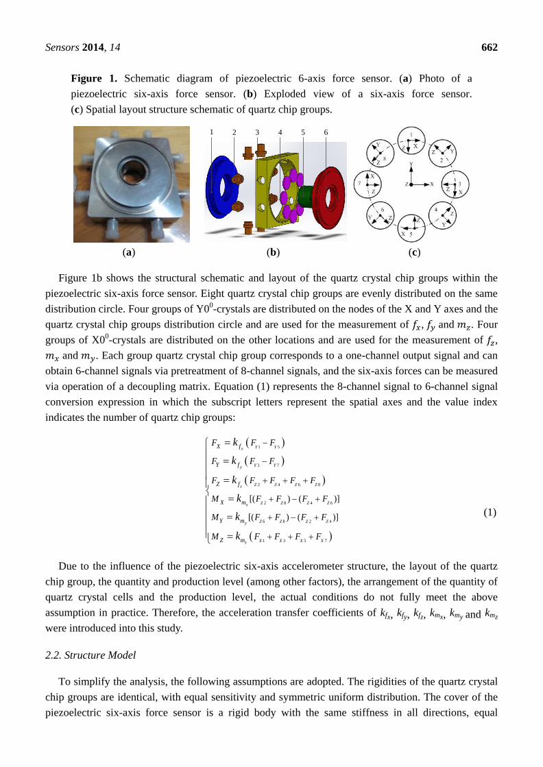
Figure 2. Block diagram of the sensor’s structure.
1
2
3
4
5
6
7
8
1O
O
2rR
h
FxFy
MxMy
Mz
Fz
XY
X1Y1
Figure 2 shows the block diagram of the piezoelectric six-axis force sensor structure. The designation
O-XYZ represents the coordinate system of the measured force functional point, and O1-X1Y1Z1
denotes the installation layout position coordinate system of the quartz crystal chip groups. The quartz
crystal chip groups are arranged along the same circle with radius is R, the distance between quartz
chip groups 2 and 4 is 2r = 1.414R, and the distance between the force and the surface of quartz crystal
chip groups is h. The component forces acting on each quartz crystal chip groups can be expressed by
Equation (2):
/
/
/
/
X1 x z y
X5 x z y
Y3 y z x
Y7 y z x
Z2 z y x x y
Z4 z y x x y
Z6 z y x x y
Z8 z y x x y
F = a / 8 + am / 8R am
F = a / 8 + am / 8R am
F = a / 8 + am / 8R am
F = a / 8 + am / 8R am
F = a / 8 + [ a h a h + am am ] / 3r
F = a / 8 + [a h a h am am ] / 3r
F = a / 8 + [a h + a h am + am ] / 3r
F = a / 8 + [ a h + a h + am + am
R
R
R
R
] / 3r
(2)
According to the Equations (1) and (2), we can obtain the piezoelectric six-axis force sensor’s
output charge Equation (3) and linear decoupling matrix CQm, where S is the cross-sectional area of the
quartz chip, Se is the available cross-sectional area of electrode, d11 and d26 are the piezoelectric moduli
of the quartz crystals:

Sensors 2014, 14 664
26
26
11
11
11
26
(
(
)
)
)
/ 2) /
/ 2) /
/
(8 / 3 8 / 3
(8 / 3 8 / 3
8 /
x
y
z
x y
y x
z
X x
Y y
Z z
X x
Y y
Z z
F f e
F f e
F f e
M m e
M m e
M m e
Q f
Q f
Q f
Q m Sr k
Q m Sr k
Q m k RS
k d S S
k d S S
k d S S
Sr f h d S
Sr f h d S
d S
(3)
26 11
26 11
11
11
11
26
/ 2 0 0 0 8 / 3 0
0 / 2 0 8 / 3 0 0
0 0 0 0 0
0 0 0 8 / 3 0 0
0 0 0 0 8 / 3 0
0 0 0 0 0 8 /
x y
y x
z
x
y
z
f m
f m
feQm
m
m
m
k d hk d r
k d hk d r
k dSC
S k d r
k d r
k d R
(4)
As can be seen from Equations (3) and (4), due to the influence of the sensor structure, the cross
coupling interferences of six-axis force sensor take place in the fy, mx, fx, my directions. These
interferences are different from traditional nonlinear coupling, and can be eliminated using a
mathematical compensation method.
3. Static Characteristics Analysis
3.1. Analytical Model
In the process of obtaining a high-precision analytical/mathematical model of the piezoelectric
six-axis force sensor from the structural model, the key difficulties lie in solving for the load transfer
coefficients kfx, kfy, kfz, kmx, kmy and kmz. To obtain the load transfer coefficients, the following
computations should be carried out. First, the transmission path of the six-axis force load on the sensor
must be analyzed. Next, the equivalent rigidity and equivalent mass of the piezoelectric six-axis force
sensor components should be solved. Finally, the load transfer coefficient expressions can be constructed.
Figure 3. The static spring equivalent model of the piezoelectric six-axis force sensor.
0k
2k3k
4k
5k
6k
7k8k
9k
10k
11k
1k
Sensors 2014, 14 665
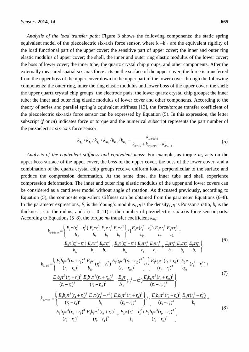
Analysis of the load transfer path: Figure 3 shows the following components: the static spring
equivalent model of the piezoelectric six-axis force sensor, where k0–k11 are the equivalent rigidity of
the load functional part of the upper cover; the sensitive part of upper cover; the inner and outer ring
elastic modulus of upper cover; the shell, the inner and outer ring elastic modulus of the lower cover;
the boss of lower cover; the inner tube; the quartz crystal chip groups, and other components. After the
externally measured spatial six-axis force acts on the surface of the upper cover, the force is transferred
from the upper boss of the upper cover down to the upper part of the lower cover through the following
components: the outer ring, inner the ring elastic modulus and lower boss of the upper cover; the shell;
the upper quartz crystal chip groups; the electrode pads; the lower quartz crystal chip groups; the inner
tube; the inner and outer ring elastic modulus of lower cover and other components. According to the
theory of series and parallel spring’s equivalent stiffness [13], the force/torque transfer coefficient of
the piezoelectric six-axis force sensor can be expressed by Equation (5). In this expression, the letter
subscript (f or m) indicates force or torque and the numerical subscript represents the part number of
the piezoelectric six-axis force sensor:
1/8/ 0/9
3/4/5 1/8/ 0/9 2/7/11
/ /x y z x y z
kk k k k k k
k k k
1
1
/ / /f f f m m m (5)
Analysis of the equivalent stiffness and equivalent mass: For example, as torque mx acts on the
upper boss surface of the upper cover, the boss of the upper cover, the boss of the lower cover, and a
combination of the quartz crystal chip groups receive uniform loads perpendicular to the surface and
produce the compression deformation. At the same time, the inner tube and shell experience
compression deformation. The inner and outer ring elastic modulus of the upper and lower covers can
be considered as a cantilever model without angle of rotation. As discussed previously, according to
Equation (5), the composite equivalent stiffness can be obtained from the parameter Equations (6–8).
In the parameter expressions, Ei is the Young’s modulus, ρi is the density, μi is Poisson's ratio, bi is the
thickness, ri is the radius, and i (i = 0–11) is the number of piezoelectric six-axis force sensor parts.
According to Equations (5–8), the torque mx transfer coefficient kmx:
2 2 2 22 2 2 2 2
3 6 5 3 6 51 1 2 2 1 1 1 1 2 21/8/ 0/9
12 7 8 7 12 7 8
2 2 2 22 2 2 2 2 2 2
3 6 5 3 6 51 1 1 1 2 2 1 1 1 1 2 2 1 1
12 7 7 12 8 7 7 8 7
( ) ( )/{ +
( ) ( )+
E r r E r rE r E r E r E r E rk
b b b b b b b
E r r E r rE r E r E r E r E r E r E r
b b b b b b b b b
1
(6)
3 3 3 3 3 32 2 2 23 3 7 6 3 3 6 7 10 3 3 7 6 3
3/4/5 8 7 8 73 3 3
7 6 10 7 10 7 6 10
3 3 3 3 3 32 23 3 7 6 3 6 7 10 3 3 6 7 10
8 73 3
7 6 7 10 10 7 10
( ) ( ) ( )= ( ) / ( )
( ) ( ) ( )
( ) ( ) ( )+ ( )
( ) ( ) (
E b r r E E b r r E b r r Ek r r r r
r r b r r r r b
E b r r E b r r E E b r rr r
r r r r b r r
3)
(7)
3 3 2 2 3 3 3 3 2 2
3 2 4 5 3 4 3 3 5 9 4 3 2 4 5 3 4 32/7/11 3 3 3
5 4 9 9 4 5 4 9
3 3 3 3 2 2 3 3
3 2 4 5 3 5 9 4 3 4 3 3 5 9 4
3 3 3
5 4 9 4 9 9 4
( ) ( ) ( ) ( ) ( )/ +
( ) ( ) ( )
( ) ( ) ( ) ( )+
( ) ( ) ( )
E b r r E r r E b r r E b r r E r rk
r r b r r r r b
E b r r E b r r E r r E b r r
r r r r b r r
(8)
Sensors 2014, 14 666
3.2. Numerical Model
To verify the effectiveness of the piezoelectric six-axis force sensor analytical mathematical model,
ANSYS software is used to pre-assess the piezoelectric six-axis force sensor static characteristics. The
analysis process primarily applies a modeling approach and load application method.
Modeling approach: In the first step, the physical structural model of the piezoelectric six-axis force
sensor is built with CAD software (i.e., SolidWorks or PRE/E), and the physical structural model is
imported into the ANSYS software. The element types and material parameters of the model can be
defined according to the material characteristics of the piezoelectric six-axis force sensor components.
The piezoelectric six-axis force sensor’s working coordinates and the quartz crystal chip groups’ local
coordinates can be constructed according to the operating conditions of the sensor and the digestion
type of the quartz crystal chips. Finally, according to the actual computational requirements, the
meshing method is determined to complete the meshing of piezoelectric six-axis force sensor.
Load application method: This approach includes the installation constraints and acting force/torque
loading on the piezoelectric six-axis force sensor. The constraints set adheres to the sensor’s
installation status, and the preload force is applied through a section of the cover. The degree of
freedom of the pedestal’s mounting surface is zero. The measured force/moments are applied to the
key point, which is established on the Z-axis and located in the same plane as the upper surface of the
piezoelectric six-axis force sensor. Additionally, the key point and the upper surface of the sensor’s
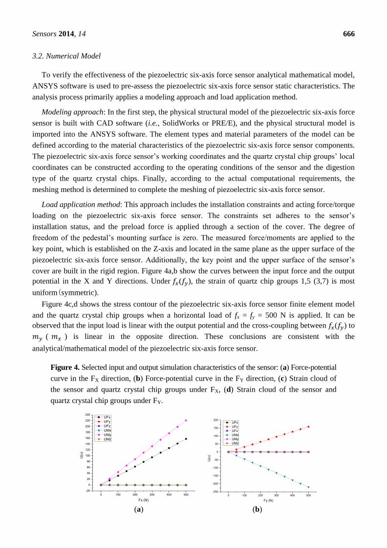
cover are built in the rigid region. Figure 4a,b show the curves between the input force and the output
potential in the X and Y directions. Under ( ), the strain of quartz chip groups 1,5 (3,7) is most
uniform(symmetric).
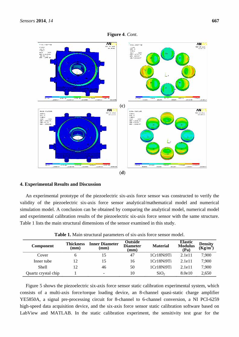
Figure 4c,d shows the stress contour of the piezoelectric six-axis force sensor finite element model
and the quartz crystal chip groups when a horizontal load of fx = fy = 500 N is applied. It can be
observed that the input load is linear with the output potential and the cross-coupling between ( ) to
( ) is linear in the opposite direction. These conclusions are consistent with the
analytical/mathematical model of the piezoelectric six-axis force sensor.
Figure 4. Selected input and output simulation characteristics of the sensor: (a) Force-potential
curve in the FX direction, (b) Force-potential curve in the FY direction, (c) Strain cloud of
the sensor and quartz crystal chip groups under FX, (d) Strain cloud of the sensor and
quartz crystal chip groups under FY.
0 100 200 300 400 500
-20
0
20
40
60
80
100
120
140
160
180
200
220
240
U(v
)
Fx (N)
UFx
UFy
UFz
UMx
UMy
UMz
0 100 200 300 400 500
-250
-200
-150
-100
-50
0
50
100
150
200
U(v
)
Fy (N)
UFx
UFy
UFz
UMx
UMy
UMz
(a) (b)
Sensors 2014, 14 667
Figure 4. Cont.
(c)
(d)
4. Experimental Results and Discussion
An experimental prototype of the piezoelectric six-axis force sensor was constructed to verify the
validity of the piezoelectric six-axis force sensor analytical/mathematical model and numerical
simulation model. A conclusion can be obtained by comparing the analytical model, numerical model
and experimental calibration results of the piezoelectric six-axis force sensor with the same structure.
Table 1 lists the main structural dimensions of the sensor examined in this study.
Table 1. Main structural parameters of six-axis force sensor model.
Component Thickness
(mm) Inner Diameter
(mm)
Outside Diameter
(mm) Material
Elastic Modulus
(Pa)
Density (Kg/m
3)
Cover 6 15 47 1Cr18Ni9Ti 2.1e11 7,900
Inner tube 12 15 16 1Cr18Ni9Ti 2.1e11 7,900
Shell 12 46 50 1Cr18Ni9Ti 2.1e11 7,900
Quartz crystal chip 1 - 10 SiO2 8.0e10 2,650
Figure 5 shows the piezoelectric six-axis force sensor static calibration experimental system, which
consists of a multi-axis force/torque loading device, an 8-channel quasi-static charge amplifier
YE5850A, a signal pre-processing circuit for 8-channel to 6-channel conversion, a NI PCI-6259
high-speed data acquisition device, and the six-axis force sensor static calibration software based on
LabView and MATLAB. In the static calibration experiment, the sensitivity test gear for the
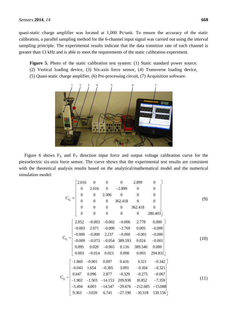
Sensors 2014, 14 668
quasi-static charge amplifier was located at 1,000 Pc/unit. To ensure the accuracy of the static
calibration, a parallel sampling method for the 6-channel input signal was carried out using the interval
sampling principle. The experimental results indicate that the data transition rate of each channel is
greater than 13 kHz and is able to meet the requirements of the static calibration experiment.
Figure 5. Photo of the static calibration test system: (1) Static standard power source.
(2) Vertical loading device, (3) Six-axis force sensor, (4) Transverse loading device,
(5) Quasi-static charge amplifier, (6) Pre-processing circuit, (7) Acquisition software.
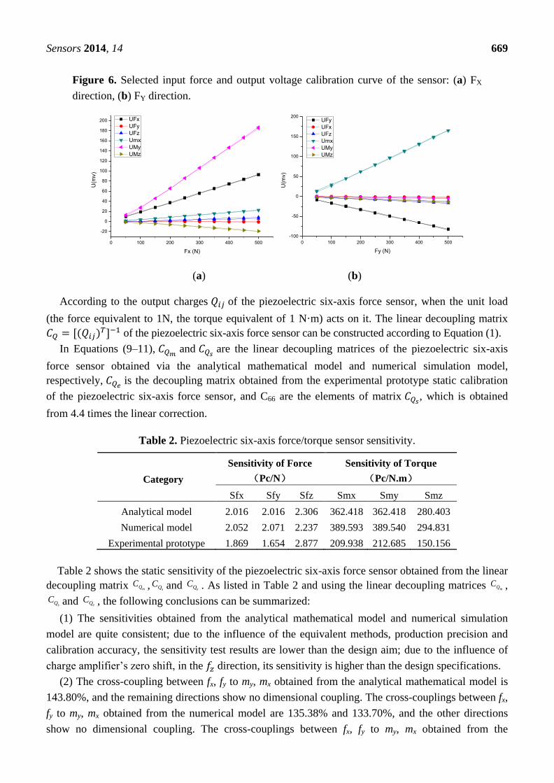
Figure 6 shows FX and FY direction input force and output voltage calibration curve for the
piezoelectric six-axis force sensor. The curve shows that the experimental test results are consistent
with the theoretical analysis results based on the analytical/mathematical model and the numerical
simulation model:
2.016 0 0 0 2.899 0
0 2.016 0 2.899 0 0
0 0 2.306 0 0 0
0 0 0 362.418 0 0
0 0 0 0 362.418 0
0 0 0 0 0 280.403
mQC
(9)
2.052 0.003 0.002 0.006 2.778 0.000
0.003 2.071 0.000 2.769 0.005 0.000
0.000 0.000 2.237 0.000 0.001 0.000
0.009 0.073 0.054 389.593 0.024 0.001
0.095 0.020 0.065 0.116 389.540 0.000
0.003 0.014 0.023 0.008 0.00
sQC
3 294.831
(10)
1.869 0.001 0.097 0.416 3.321 0.342
0.043 1.654 0.305 3.093 0.104 0.321
0.047 0.096 2.877 0.329 0.275 0.067
1.902 1.503 14.153 209.938 10.852 7.359
5.494 4.003 14.547 29.676 212.685 15.088
9.363 3.020 6.741 2
eQC
7.190 10.318 150.156
(11)
Sensors 2014, 14 669
Figure 6. Selected input force and output voltage calibration curve of the sensor: (a) FX
direction, (b) FY direction.
0 100 200 300 400 500
-20
0
20
40
60
80
100
120
140
160
180
200
U(m
v)
Fx (N)
UFx
UFy
UFz
Umx
UMy
UMz
0 100 200 300 400 500
-100
-50
0
50
100
150
200
U(m
v)
Fy (N)
UFy
UFx
UFz
Umx
UMy
UMz
(a) (b)
According to the output charges of the piezoelectric six-axis force sensor, when the unit load
(the force equivalent to 1N, the torque equivalent of 1 N·m) acts on it. The linear decoupling matrix
of the piezoelectric six-axis force sensor can be constructed according to Equation (1).
In Equations (9–11), and
are the linear decoupling matrices of the piezoelectric six-axis
force sensor obtained via the analytical mathematical model and numerical simulation model,
respectively, is the decoupling matrix obtained from the experimental prototype static calibration
of the piezoelectric six-axis force sensor, and C66 are the elements of matrix , which is obtained
from 4.4 times the linear correction.
Table 2. Piezoelectric six-axis force/torque sensor sensitivity.
Category
Sensitivity of Force
(Pc/N)
Sensitivity of Torque
(Pc/N.m)
Sfx Sfy Sfz Smx Smy Smz
Analytical model 2.016 2.016 2.306 362.418 362.418 280.403
Numerical model 2.052 2.071 2.237 389.593 389.540 294.831
Experimental prototype 1.869 1.654 2.877 209.938 212.685 150.156
Table 2 shows the static sensitivity of the piezoelectric six-axis force sensor obtained from the linear
decoupling matrix mQC , sQC and eQC . As listed in Table 2 and using the linear decoupling matrices mQC ,
sQC and eQC , the following conclusions can be summarized:
(1) The sensitivities obtained from the analytical mathematical model and numerical simulation
model are quite consistent; due to the influence of the equivalent methods, production precision and
calibration accuracy, the sensitivity test results are lower than the design aim; due to the influence of
charge amplifier’s zero shift, in the direction, its sensitivity is higher than the design specifications.
(2) The cross-coupling between fx, fy to my, mx obtained from the analytical mathematical model is
143.80%, and the remaining directions show no dimensional coupling. The cross-couplings between fx,
fy to my, mx obtained from the numerical model are 135.38% and 133.70%, and the other directions
show no dimensional coupling. The cross-couplings between fx, fy to my, mx obtained from the
Sensors 2014, 14 670
experimental prototype calibration are 177.69% and 187.00%; due to the influence of manufacturing
precision, the highest level of cross coupling in the other direction reaches 18.11%,but these
interferences are linear coupling, and can be eliminated using a mathematical compensation method.
(3) The force isotropy is 0.6531, 0.6467 and 0.7098, and the moment isotropy is 0.7737, 0.7567 and
0.6233, as obtained from the analytical mathematical model, numerical simulation model and
experimental prototype of the piezoelectric six-axis force sensor, respectively. The force/torque
isotropy of the analytical mathematical model is broadly consistent with that of the numerical
simulation model. Because of the influence of machining accuracy, deviations are observed among the
experimental prototype and the analytical mathematical model and numerical simulation model of the
piezoelectric six-axis force sensor. However, due to the test gear, the quasi-static charge amplifier
affects the sensitivity of the piezoelectric force sensor measurement system, and therefore, the
force/torque isotropy of the piezoelectric six-axis force sensor could be greatly improved by selection
of better test gear with respect to the charge amplifier.
5. Conclusions
In this paper, we have investigated a novel six axis force/torque sensor based on double quartz
crystal chip groups. Its analytical mathematical model and numerical simulation model are presented.
The research conclusions can be drawn as follows:
1. The sensor’s static performances (i.e., static sensitivity, impedance,anti-humidity) are better
than six axis force/torque sensor based on signal quartz crystal chip groups ([3]).
2. Due to the influence of the six axis force/torque sensor’s spatial structure, there are some cross
coupling interferences take place in the fy, mx, fx, my directions, and these static cross coupling
interferences are linear coupling and can be eliminated using a mathematical compensation method.
3. These sensors’ analytical mathematical model which is derived using the material mechanics
and theoretical mechanics, and numerical simulation model based on ANSYS is presented, are
effective. We can realize the design of these sensors’ static performance through the two models.
4. Due to the influence of the simulation method, production precision and calibration accuracy,
the test accuracy of the sensor experimental prototype in the direction does not completely meet the
design requirements, the simulation result in the direction require linearity correction. These issues
will be the focus of future research for implementing the static-active design of the piezoelectric multi-
axis force senor based on a multi-point support structure.
Acknowledgments
This work is supported by the Fundamental Research Funds for the Central Universities
(No. 1061120131205), the Natural Science Foundation Project of Chongqing China CSTC
(No. CSTC2012JJA40024), and the National High Technology Research and Development Program of
China (863 Program) (No. 2012AA040107).
Conflict of Interest
The authors declare no conflict of interest.
Sensors 2014, 14 671
References
1. Kim, H.M.; Yoon, J.; Kim, G.S. Development of a six-axis force/moment sensor for a
spherical-type finger force measuring system. IET Sci. Meas. Technol. 2012, 6, 96–104.
2. Dwarakanath, T.A.; Bhutani, G. Beam type hexapod structure based six component force-torque
sensor. Mechatronics 2011, 21, 1279–1287.
3. Liu, J.; Qin, L.; Li, M.; Liu, J.; Xue, L. Development of parallel piezoelectric six-axis force/torque
sensor. Opt. Precis. Eng. 2011, 19, 1569–1579.
4. Zhang, W.G. A new distributing and decoupling method of six degree of freedom force sensors.
J. Nanjing Univ. Aeronaut. Astronaut. 1999, 31, 221–222.
5. Chao, L.-P.; Chen, K.T. Shape optimal design and force sensitivity evaluation of six-axis force
sensors. Sens. Actuators A Phys. 1997, 63, 105–112.
6. Wu, B.Y.; Wu, Z.C.; Shen, F. Study on inertia coupling characteristics of 6-axis force sensor in
mult-dimensional acceleration field. Chin. J. Sen. Actuators 2008, 21, 1686–1690.
7. Dither, D. Measurement sensor for a linking wrench between two mechanical parts, as well as its
manufacturing process. US Patent 5,821,431, 13 October 1998.
8. Liu, W.; Ling, S.; Jia, Z.Y.; Wang, Y.Q. Piezoelectric six axis heavy force sensor. China
Invention Patent, Application Number 200710157931.2, 26 March 2008.
9. Liu, W.; Li, Y.J.; Jia, Z.Y.; Zhang, J.; Qian, M. Research on parallel load sharing principle of
piezoelectric six-dimensional heavy force/torque sensor. Mech. Syst. Signal Process. 2011, 25,
331–343.
10. Nemirovsky, Y.; Nemirovsky, A.; Muralt, P.; Setter, N. Design of a novel thin film piezoelectric
accelerometer. Sens. Actuators A Phys. 1996, 56, 239–249.
11. Tong, Z.Z.; Jiang, H.Z.; He, J.F.; Duan, G.R. Optimal design of isotropy performance of
six-dimensional force sensor based on standard stewart parallel structure lying on a circular
hyperboloid of one sheet. Acta Aeronaut. et Astronaut. Sin. 2011, 32, 2327–2334.
12. Wang, Z.J.; Yao, J.T.; Xu, Y.D.; Zhao, Y.S. Hyperstatic analysis of a fully pre-stressed six-axis
force/torque sensor, Mech. Mach. Theory 2012, 57, 84–94.
13. Liu, J. Study on Basic Theroy and Key Technologies of Flat Piezoelectric Six Axis Force/Torque
Sensor. Ph.D. Thesis, Chongqing University, Chongqing, China, 2011.
© 2014 by the authors; licensee MDPI, Basel, Switzerland. This article is an open access article
distributed under the terms and conditions of the Creative Commons Attribution license
(http://creativecommons.org/licenses/by/3.0/).