activities on laser-fusion, experimental reactor … on laser-fusion, experimental reactor based on...
TRANSCRIPT

Activities on laser-fusion, experimental reactor based on fast
ignition scheme
T. Norimatsu Presented at
Japan-US Workshop on Fusion Power Plants and Related Advanced Technologies
with participations from China and Korea February 26-28, 2013 at Kyoto University in Uji, JAPAN

ILE, Osaka
Outline
• Introduction
– Current status of FI
• Present status of design committee on laser fusion experimental reactor
• Topics in working groups
– Point design of FI target
– Stability of FI target after sabot release

ILE, Osaka
Fast ignition has potential to achieve ignition and burn with
smaller laser energy
• Since fast ignition needs no hot central core, high density compression can be achieved with smaller laser energy than that for central ignition.
• FI is robust to RT instabilities
Key point is the heating efficiency.

ILE, Osaka
2. LFEX laser – construction and tuning
• Nov, 2008 Precision alignment of pulse compressor
• Dec, 2008 Target irradiation with high-power beam started
• Feb, 2009 Irradiation of Fast Ignition (FI) target started
• June, 2009 FI integrated experiment started (5 ps)
• Sept, 2009 FI integrated experiment (1 ps) / 1 beam
• Aug, 2010 FI integrated experiment (1 ps) / 2 beams
Main amplifier subsystem
Rear-end subsystem
GEKKO XII
Interaction chamber
4

ILE, Osaka
Marks experiments Lines simulations dashed lines : for 2002, 2009 exp’t solid lines : for 2010 exp’t
0.01 0.1 1 1010
4
105
106
107
108
109
Laser energy on target [kJ]
DD
neu
tron
yie
ld
★ 2010 exp’t ● 2002 results
● 2009 1ps ● 2009 5ps
0.01 0.1 1 100.1
1
10
Ion
tem
peratu
re [
keV
]
Laser energy on target [kJ]
★ 2010 exp’t ● 2002 results
● 2009 1ps ● 2009 5ps
5
Not yet optimized: input energy and heating efficiency to be increased
Initial density profile of the core plasma assumed: Gaussian profile rmax = 100 g/cm3, R = 20mm
Goal
2010 results reconfirmed 2002 exp’t, heating efficiency of 10-20% achieved

ILE, Osaka
・In 2011, laser energy was increased, but no reliable data was obtained in integrated experiments because of very strong electro magnetic noise. Improvement of diagnostic equipment and elemental researches on the heating efficiency are under way using the two beams of LFEX laser in 2011 and 2012.
6
Present status of LFEX laser system

ILE, Osaka
Outline
• Introduction
• Present status of design committee on laser fusion experimental reactor
• Topics
– Point design of FI target
– Stability of FI target after sabot release

ILE, Osaka
Conceptual design committee for experimental reactor was organized after
Feb. 2012 with support of IFE Forum. • Chair Y. Kozaki, Co-chair T. Norimatsu, S. Fujioka
Advisory group K. Ueda, A. Endo, Y. Ogawa, Y. Kato, H. Kan, M. Kikuchi, H. Tanigawa, K. Tobita, M. Nishikawa and K. Tomabechi
Core plasma group H. Shiraga Y. Arikawa T. Ozaki H. Sakagami K. Shigemori T. Jhozaki A. Sunahara T. Taguchi M. Nakai H. Nagatomo H. Nishimura S. Fujioka M. Murakami
Fueling group T. Norimatsu A. Iwamoto T. Endo N. Sato R. Tsuji H. Yoshida
Laser group H. Fujita T. Kawashima R. Yasuhara T. Yanagitani
Plant system group K. Okano Y. Ueda R. Kasada Y. Kajimura Y. Kitagawa T. Goto M. Kondo K. Tomabechi T. Hayashi T. Fukada Y. Someya S. Fujioka T. Norimatsu
The goal of this committee is to clarify basic specifications and the system scenario for each phase of the experimental reactor.

ILE, Osaka
Milestone of experimental reactor
Phase 1 Phase 2 Phase 3
Purpose Repeated fusion burns Physics
Send electric power to net Tritium breeding Material test
Operation mode 100 shots (1 batch of cryogenic DT
targets)
1 week 0.5 year
Fusion yield 40MJ~80MJ 40MJ~80MJ 40MJ~80MJ
Electric power No cooling system 0MWe~50MWe 60-180MWe
Gain 100 100 100
Laser energy 400kJ~800kJ Comp. 400+Heating 200, 2 w,
30ps
400kJ~800kJ 400kJ~800kJ
Chamber type Solid wall, Ferrite No W armor
1st half, Solid wall, Ferrite 2nd half, liquid wall
Liquid wall
Blanketト No blanket Average temperature
increase by 200 oC
①Solid breeder, water cooling
②LiPb self cooling
①Solid breeder, water cooling
②LiPb self cooling
Chamber radius 2m~4m 3m~1.5m 3m~1.5m
The laser system will be commonly used for all phases.

ILE, Osaka
Issues under discussion 1
• 1) Continuity of technologies and tritium breeding for phase I through III. – The laser system is common to all phases.
– Chamber I (Dry wall, no cooling)
– 1st Chamber II (Dry wall, solid bleeder cooled with water)
– 2nd chamber II (Wet wall, Liquid LiPb blanket) (This chamber will be also used in Phase III)
• How to prepare the initial inventory of tritium?
Replace
New site in the same building

ILE, Osaka
Issues under discussion 2
• 2) Plant system including radiation safety. – Tritium barrier – Neutron shield – Neutron activation
• Phase I, 100shots/10min, 86mSv/h (@1m from chamber surface). 20mSv/h after 1 day cooling
• Man can access in short time (<50mSv/year) • Phase II and later, 40MJ×4Hz×> 2 month, 300Sv/h (@1.5
m from chamber surface) • No access, Can electric devices work?
– Accidental tritium release

ILE, Osaka
Issues under discussion 3
• 3)Protection of beam port and final optics (Phase 3 and later)
Protection by a magnetic field
How to make 1 T field?
Pulse operation, The coil will be made with liquid LiPb and SiC.

Polar-drive design can be optimized systematically
M. Murakami, Fusion Engineering and Design 44 (1999) 111
This analytical tool is based on the assumption that
all the beam axes pass through the target center. We
have therefore new analytical model, in which the
beam pointing, the oblique effect, and allocated
energy allocated to each beam-ring.

NB = 28 can provide heating uniformity of 99%,
which is sufficient for fast ignition.
2p(1-cosDq) =4p
NB
, nd
=2p
Dq»
p
2N
BKidder Kidder 1976 :
28

ILE, Osaka
Polar drive enables access for maintenance from the top.
7 beams/cone 4 cones
I0
0.53I0

Top view
Side view
Automatic mirror change system will be tested in phase III.
Neutron shield 1st Vacuum gate
2nd vacuum gate

Top view
Side view
Final optics

Top view
Side view
Final optics

Top view
Side view
Final optics
Cool down for a month

Top view
Side view
Final optics

ILE, Osaka
Neutron and tritium barrier for beam line
Laser
ILE, Osaka
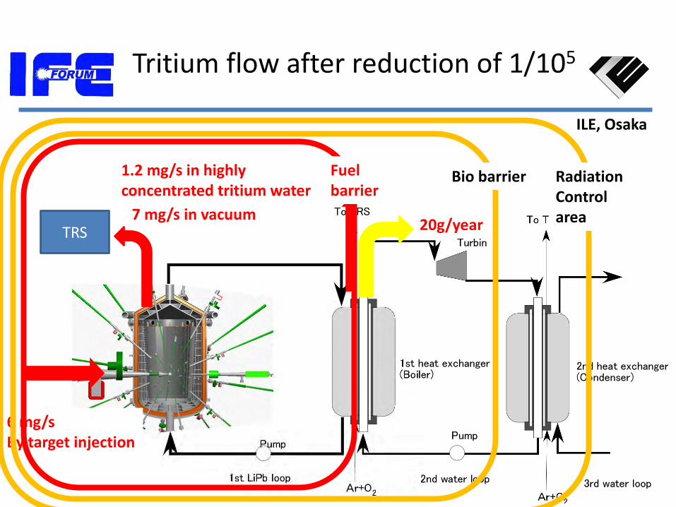
Tritium flow after reduction of 1/105
TRS 7 mg/s in vacuum
1.2 mg/s in highly concentrated tritium water
20g/year
6 mg/s By target injection
Radiation Control area
Fuel barrier
Bio barrier

ILE, Osaka
Outline
• Introduction – Fast ignition
– Current status of FI
• Present status of design committee on laser fusion experimental reactor
• Topics in working groups – Point design of FI target (Simulation and core plasma
group)
– Stability of FI target after sabot release

Commercial reactor
Experimental reactor

Requirements for 50MJ output
Core density [g/cm3] Core areal density R [g/cm2] Burn fraction BT Fusion output Ef [MJ]
2
5.1,1min
7
R
R
RBT
r
r
r
24
2
5
5.1,1min
7
)(11013.14[MJ]
5
R
R
REB
m
ME DTT
p
FF
r
r
r
r
50MJ
50MJ fusion output, R R MF BT
200g/cm3 1.90g/cm2 93um 0.71mg 0.21 300g/cm3 2.35g/cm2 77um 0.60mg 0.25 400g/cm3 2.75g/cm2 68um 0.53mg 0.28 30MJ fusion output, R R MF BT
200g/cm3 1.65g/cm2 83um 0.47mg 0.19 300g/cm3 2.04g/cm2 68um 0.40mg 0.23 400g/cm3 2.38g/cm2 60um 0.35mg 0.25
50MJ
30MJ 30MJ
40MJ 40MJ

R: 40 μm
Requirement for rR (2.3 g/cc) will be realized with 390 kJ laser.

Deposition range dependence on heating laser condition
2/12
m
219 m06.1W/cm102.1[MeV]
m
mlaserig
h
IT
[MeV]6.0][g/cm2hRTf
fR: range reduction/lengthening factor depends on stopping power model.
Hot electron temperature (Wilks’s model)
Deposition range
1019 1020 1021 10221
10
100
T ho
t [M
eV
]
IL [W/cm2]
1w
2w
3w
0.1
1
10
R [
g/cm
2]
For R<R0 < 1.2g/cm2, IL [W/cm2] < 5x10¹⁹ (1w), 2x10²⁰ (2w), 4x10²⁰ (3w) Lower than required intensity for optimal condition.
r[g/cc] Eheating[kJ] Heating time[ps] Spot size[mm] Intensity[W/cm2] Eheating laser[kJ](coupling eff.)
200 39 30 30 0.46×10²⁰ 195 (0.2) / 390 (0.1)
300 18 21 20 0.69×10²⁰ 90 (0.2) / 180 (0.1)
400 11 17 15 0.90×10²⁰ 55 (0.2) / 110 (0.1)
500 7 14 12 1.10×10²⁰ 35 (0.2) / 70 (0.1)
For 300g/cm3 core, required laser intensity (under the optimal condition & laser spot = beam spot) is IL = 3.5x10²⁰W/cm2 (hL->core=20%) ~ 6.9x10²⁰W/cm2 (hL->core=10%).

Heating process
Experimental check required →To be improved
In FIREX-1
Model for heating process
Physical process consists of 3 major elements
Energy of heating laser to that of hot electrons
Fraction of hot electrons that reach the core
Energy deposition efficiency

ILE, Osaka
Self-generated B-field
高速電子流が作る自己生成磁場
ff jjBt
B
hh
m
h
0
Extended & Tapered cone tip
Pointed tip Cone
Gradient of conductivity generates magnetic field.

ILE, Osaka
z [m] 0 50 100
r [m
m]
r [m
m]
0 50
0
50
r [m
m]
0 50
100 z [m]
0 50
B
nf
energy dep. 0 1 2 3
0
5
10
hfe
->co
re [
%]
External Bz [kT]
DLC Tongari Au flat top
x 2.6 (Self B)
x 3.4 (External B)
x 8.6
Self-generated B Self-generated
+External B(1 kT) Coupling efficiency of
electrons to core
We can expect increase of heating efficiency by 10 times.

Summary for heating laser 300 g/cm3 core design wavelength ig
laser 0.53 m ) Energy Eig
laser ~ 200 kJ Intensity Iig
laser ~ 2x10²⁰ W/cm2
Spot riglaser ~ 33 m
Duration iglaser ~ 30 ps
Coupling eff. hig
laser = 20% Electron T Th ~ 2 MeV Radius of heat ing rb = 33 mm Beam guide is important
Energy of heating laser can be reduced with higher r.
r [g/cm3] Eiglaser [kJ] Iig
laser[W/cm2] iglaser[ps]
300 161 2.24x10²⁰ 21 400 125 2.15x10²⁰ 17
500 114 2.38x10²⁰ 14

ILE, Osaka
Control of fast electrons by magnetic field seems the key point to improve
the heating efficiency.
• A magnetic field exceeding 1kT was obtained by using a laser-driven, capacitor-coil target.
• Numerical simulation indicated that the heating efficiency can be increased with the external B by a factor of 8 and with self-generated B by a factor of 2.6.
• Next issue; How to increase the self-generated B field?

ILE, Osaka
Outline
• Introduction
– Fast ignition
– Current status of FI
• Present status of design committee on laser fusion experimental reactor
• Topics in working groups
– Heating efficiency
– Stability of FI target after sabot release (Fueling group)

ILE, Osaka
Scenario for fueling
I
Phase I Phase II and later

ILE, Osaka
Loading of FI targets in sabots
Sabot loading section Large revolver allows sufficient time to cool
Sabot
Target
Gas reservoir
From DT fill station
Gas
Target

ILE, Osaka
Injection system consists of gas gun followed by coil gun and tracking section.
仕様 Injection velocity 100+/-2 m/s Rep rate 2 Hz Pointing +/- 1 mrad Operation power including freezer 500 kW
投入追尾
Divergence of flight direction and tumbling of target must be experimentally checked.

ILE, Osaka
Real size injection system was constructed at ILE to check the stability of
FI target after sabot release.
37

ILE, Osaka
First campaign revealed many issue to be improved.
38
↑ Successful injection ↑ Failure
Velocity (m/s) Divergence (mrad)
Tumbling (rad/s)
Final goal 100+/-1 +/-1 +/- 0.7
First campaign
114+/-23 +/-1.97 10+/-43
We expect +/- 4 in the next campaign after optimization of the reservoir volume.

ILE, Osaka
Issue to be checked
• Is deceleration by eddy current unstable for FI target?
• Next plan
– Shield effect by sabot and optimization of target mount
3.9 mm
15 o 9 mm 11 mm
5.4 mm 3 mm 4.0 mm
Plastic coating Prabolic mirror
Foam insulator Solid DT+Foam
Mas center Center for deceleration
If sabot is made with higher conductive material, dB/dt in sabot will be smaller

ILE, Osaka
Summary
• Design committee for experimental reactor based on FI scheme will summarize the final report by December 2013.
• Critical issues are the heating efficiency, tumbling of injected target, and dumping of stirred laser beam.
• Influence of B field on the heating efficiency will be experimentally confirmed in the next campaign (Aug. 2013).
• Thank you for your attention!