activity booklet of fischertechnik oeco energy
DESCRIPTION
Activity Booklet of fischertechnik Profi Oeco EnergyTRANSCRIPT


Seite 1 – 22
PROFI OECO ENERGY
Das Begleitheft zum Baukasten
Für alle, die wissen wollen,
„was dahinter steckt“.
D Page 23 – 44
PROFI OECO ENERGY
The Activity Booklet for the
Construktion Kit
For everyone who wants to know
“what´s behind it“.
Page 45 – 66
PROFI OECO ENERGY
Le manuel d’accompagnement
due jeu de construction
Pour tous ceux qui veulent savoir
« ce qu´il y a derrière ».
F Blz. 67 – 88
PROFI OECO ENERGY
Het begeleidend boekje van de
bouwdoos
Voor iedereen die wil weten wat
„erachter zit“.
Página 89 – 110
PROFI OECO ENERGY
El cuaderno adjunto para el kit de
costrucción
Para todos aquellos que quieren saber
„qué hay detrás de las cosas“.
E Página 111 – 132
PROFI OECO ENERGY
O auxiliar do kit
Para Todos osque querem saber
“como a coisa funciona por dentro“.
P
NL
Il libretto di istruzioni per la scatola di montaggio. Per tutti quelli che vogliono sapere „che cosa c‘è dietro“. File scaricabile dal sito www.fi schertechnik.de/didactic
Το συνοδευτικό βιβλίο για το κουτί κατασκευών. Για όλους που θέλουν να ξέρουν ‚τι βρίσκεται από πίσω‘.Το αρχείο μπορείτε να το κατεβάσετε από το www.fi schertechnik.de/didactic
Сопроводительная инструкция к конструктору. Для всех, кто хочет знать, „что за этим кроется“. Файл для загрузки на www.fi schertechnik.de/didactic
组合部件的随附说明书。对于所有想知道“究竟诀窍是什么”的人们。以在网站 www.fi schertechnik.de/didactic 中下载文件
I
CN
RU
P R O F I O E C O E N E R G Y
GR
0 Oeco Energy U2+3 .indd 20 Oeco Energy U2+3 .indd 2 22.01.2014 11:08:4822.01.2014 11:08:48
23
P R O F I O E C O E N E R G Y A C T I V I T Y B O O K L E T
ContentsEnergy from renewable sources P. 24
Oil, coal, nuclear power P. 24
Water, wind, sun P. 24
Energy P. 25
Water energy P. 25
Hammer mill P. 25Convert water energy into electricity P. 26Water turbine with LED P. 27
Wind energy P. 27
Convert wind energy into motion P. 28Convert wind energy into electricity P. 29
Solar power P. 30
Basics P. 30Convert solar power into electricity P. 30Solar models with one solar module P. 31Solar models with two solar modules – Parallel connection P. 32Series connection P. 33Store electric energy P. 34Electric vehicle with solar charging station P. 34Goldcap energy store P. 34Inverse-parallel connection P. 35Eco-house P. 37
Fuel cell preview P. 38
Profi Oeco Energy + Fuel Cell Kit from P. 39
2 OecoEnergy_GB_2.Aufl.indd 232 OecoEnergy_GB_2.Aufl.indd 23 22.01.2014 15:19:1422.01.2014 15:19:14

24
P R O F I O E C O E N E R G Y A C T I V I T Y B O O K L E T
Energy from
renewable
sources
Oil, coal,
nuclear power
Water, wind,sun
■ Every single day, we need an enormous amount of energy. Let's take a look at a normal day:
In the morning you are woken up by your radio alarm clock. This gets electricity from the socket. After getting up, you switch on the light and shower with hot water, which has been heated by the oil or gas-fi red central heating system. You then dry your hair with an electric hair dryer and clean your teeth using an electric toothbrush. You make yourself a tea or coffee for breakfast. You boiled the water on an electric or gas stove. The sandwich to eat during your break, which you prepared the night before, was stored in the refrigerator over night. You take the bus or tram to get to school, or your parents drive you there by car. Buses, trams and cars consume fuel. We could carry on in this way, listing all the things for which you need energy. The list would be endless. Summing up, we all need an enormous amount of energy.
■ And where does this energy come from? We get a large part of it from fossil fuels: natural gas, oil and coal. But part of our electricity requirement is also covered by nuclear energy. Yet these types of energy production have different disadvantages:
• Fossil fuel reserves on the earth are limited.• The combustion of oil and coal produces harmful substances (pollutants) that
pollute the environment, and CO2 that is responsible for the continuous heating of the earth's atmosphere (global warming).
• Despite high safety standards, there is always a potential risk of a radioactive accident when nuclear energy is used. The process also produces radioactive wastes, which will still be emitting radioactivity a thousand years from now.
■ A good enough reason to look around for alternatives, which are environmentally friendly and of which unlimited supplies are available. These alternative forms of energy exist. They are called regenerative (renewable) energy sources, or renewables.With your Profi Oeco Energy kit you will examine energy production from:
Water – wind – sun
Unlike fossil fuels, unlimited quantities of these energy sources are available, and none of the disadvantages described above occur when they are used.
You will use numerous models to see how these energy sources can be used to generate and store electricity and drive fi schertechnik models.
2 OecoEnergy_GB_2.Aufl.indd 242 OecoEnergy_GB_2.Aufl.indd 24 22.01.2014 15:19:1522.01.2014 15:19:15

25
P R O F I O E C O E N E R G Y A C T I V I T Y B O O K L E T
Energy
Convert water energy
into motion ...
... with the water wheel
... with the hammer mill
■ We constantly talk about energy, but what does it mean and how can it be measured?
We need energy: • to accelerate a body or • to move it against a force, • to heat a substance, • to compress a gas, • to get an electric current to fl ow and • to emit electromagnetic waves. • Plants, animals and human beings need energy to live.
The unit with which energy and work is measured is called the joule (J).
If you want to know more about energy, you will fi nd interesting articles on the Internet and in text books.
■ The invention of the water wheel was a milestone in the development of technology. Because humans could now use mechanical energy in addition to muscle power – with the help of water power (hydropower).
■ A hammer mill is a forge with a hammer driven by water power. The rotational movement of the water wheel causes periodic lifting of the hammer via a camshaft; gravity then causes the hammer to hit the workpiece held between the anvil and the hammer. The few hammer mills still in existence today and still used for production are mainly electrically operated.
2 OecoEnergy_GB_2.Aufl.indd 252 OecoEnergy_GB_2.Aufl.indd 25 22.01.2014 15:19:1522.01.2014 15:19:15

26
P R O F I O E C O E N E R G Y A C T I V I T Y B O O K L E T
Hammer mill ■ Most of these plants were situated on strong streams or rivers, as the forges were driven by water power (hydropower).
You will now build the hammer mill model to illustrate this drive principle (see assembly instructions).
You can hold the water wheel under the faucet, to start it moving.
Task 1:What are the disadvantages of this form of water energy use?
• The energy can only be used where water fl ows (streams or rivers).• The energy cannot be stored. It has to be used immediately, when it is available.• The energy is only available for a limited purpose.
■ For hundreds of years, humans have used the kinetic energy of water to directly drive machines. As industrialization developed, direct use of water energy was replaced by electric current (electricity).
Convert water energy into electricity
2 OecoEnergy_GB_2.Aufl.indd 262 OecoEnergy_GB_2.Aufl.indd 26 22.01.2014 15:19:1522.01.2014 15:19:15

27
P R O F I O E C O E N E R G Y A C T I V I T Y B O O K L E T
Water turbine with LED
■ A water turbine is a turbine which harnesses water power so that it can be used. In a water power plant (hydroelectric power plant), the energy from the fl ow of water is converted into mechanical energy by the water turbine. The turbine is rotated by the fl owing water. The rotation of the turbine shaft drives a generator, which converts the rotational energy into an electric current (electricity).The rotors of such turbines have a diameter of up to 11m.
Now build the model of a water turbine (see assembly instructions).Hold the water wheel under a faucet and let the wheel turn fast enough for the LED to light up. Note the rotational direction of the wheel given in the assembly instructions.
Task 1:How does the water turbine work?
The water wheel transfers its rotational energy onto the transmission wheel. A V-belt (rubber band) transfers the rotational movement onto the drive wheel of the solar motor. This acts as a generator and converts the rotational energy into electric energy and causes the light emitting diode (LED) to light up.
Caution: The LED is solely intended to show how electricity can be generated with the solar motor. Operate it with 2 V direct voltage maximum. It is immediately broken at higher voltages. You must also ensure that the motor does not come into contact with water.
■ Humans have been harnessing wind energy for hundreds of years. The wind was used on the one hand for transportation by sailing ships or balloons; on the other hand, wind energy was used to do mechanical work with the help of windmills and water pumps.
Wind energy
Engraving of a water turbine
Solar motor
Light emitting diode
2 OecoEnergy_GB_2.Aufl.indd 272 OecoEnergy_GB_2.Aufl.indd 27 22.01.2014 15:19:1522.01.2014 15:19:15

28
P R O F I O E C O E N E R G Y A C T I V I T Y B O O K L E T
Convert wind energy into motion
■ Just like full-scale windmills, in the windmill model with pump the wind energy is converted into kinetic energy.
A windmill is an engineering structure or building, which uses its sails (blades) turned by the wind (kinetic energy) to produce rotational energy. The rotational movement is transferred to the bottom part of the building by a large cogwheel or gear wheel and an output shaft. Gear wheels and defl ection wheels guide the rotational movement onto the mechanically driven pump.
■ Build the model of a windmill with pump (see assembly instructions).
Experiment:How can you get the windmill to start moving?
Try different techniques (blow on it, hair dryer, ventilating fan, wind or hold the model in your hand and spin in a circle as fast as you can).
2 OecoEnergy_GB_2.Aufl.indd 282 OecoEnergy_GB_2.Aufl.indd 28 22.01.2014 15:19:1622.01.2014 15:19:16

29
P R O F I O E C O E N E R G Y A C T I V I T Y B O O K L E T
Convert wind energy into electricity
■ Following the discovery of electricity and the invention of the generator, the natural idea was to use wind energy to generate electricity. Initially, windmill concepts were merely modifi ed. Instead of converting the kinetic energy of the wind into mechanical energy, it was used for the production of electrical energy by a generator. As fl uid mechanics developed, the structures and sail shapes became more specialized and nowadays they are called wind power stations. Since the oil crisis in the 1970s, there has been increased research worldwide to fi nd alternative methods of producing energy and therefore the development of modern wind power stations was also advanced.
Task:Build the wind power station model, which lights up a light emitting diode (LED). (See assembly instructions)
■ The windmill transfers its rotational energy onto the transmission wheel. A V-belt (rubber band) transfers the rotational movement onto the drive wheel of the solar motor. This acts as a generator, it converts the rotational energy into electric energy and causes the light emitting diode to light up.Before starting, double check that the propeller rotates in the correct direction and check for correct polarization of the LED (see assembly instructions).
Solar motor
Light emitting diode
2 OecoEnergy_GB_2.Aufl.indd 292 OecoEnergy_GB_2.Aufl.indd 29 22.01.2014 15:19:1622.01.2014 15:19:16
30
P R O F I O E C O E N E R G Y A C T I V I T Y B O O K L E T
■ Solar power is the name given to energy produced by the sun through nuclear fusion, part of which reaches the earth as electromagnetic radiation (radiant energy). Most of this energy is used to heat our planet.
With the help of solar technology, solar power can be used in different ways:• Solar collectors produce heat or thermal energy (to heat water or
for space heating)• Solar power plants generate electric energy by converting heat into
water vapor (steam) • Solar cookers or solar stoves heat meals• Solar cells generate direct electric current (photovoltaics)
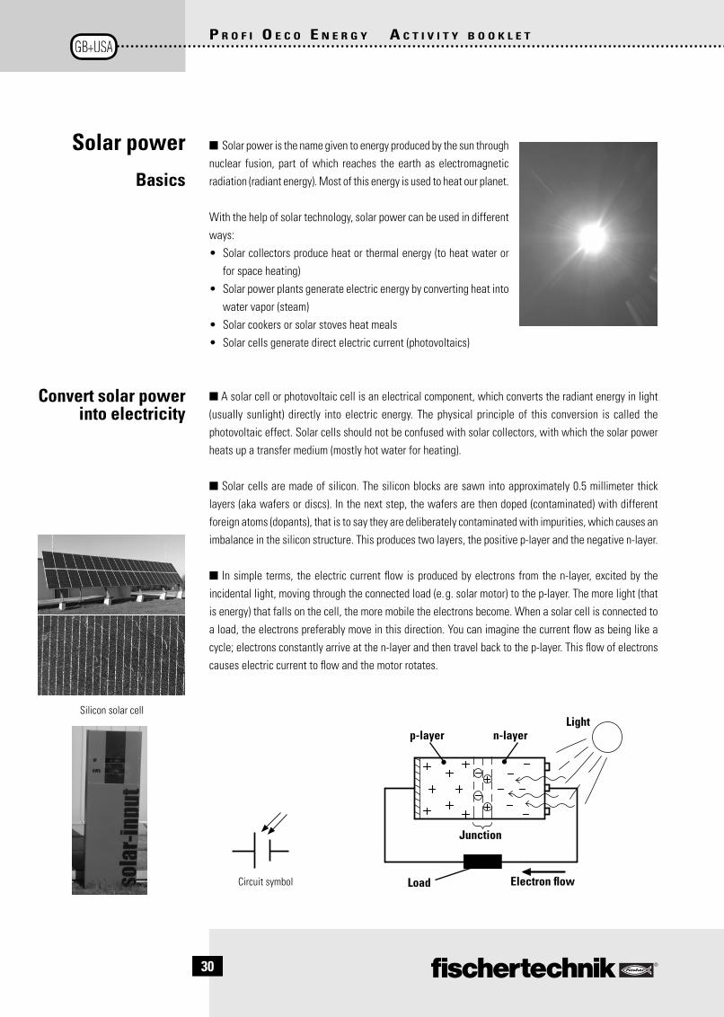
■ A solar cell or photovoltaic cell is an electrical component, which converts the radiant energy in light (usually sunlight) directly into electric energy. The physical principle of this conversion is called the photovoltaic effect. Solar cells should not be confused with solar collectors, with which the solar power heats up a transfer medium (mostly hot water for heating).
■ Solar cells are made of silicon. The silicon blocks are sawn into approximately 0.5 millimeter thick layers (aka wafers or discs). In the next step, the wafers are then doped (contaminated) with different foreign atoms (dopants), that is to say they are deliberately contaminated with impurities, which causes an imbalance in the silicon structure. This produces two layers, the positive p-layer and the negative n-layer.
■ In simple terms, the electric current fl ow is produced by electrons from the n-layer, excited by the incidental light, moving through the connected load (e.g. solar motor) to the p-layer. The more light (that is energy) that falls on the cell, the more mobile the electrons become. When a solar cell is connected to a load, the electrons preferably move in this direction. You can imagine the current fl ow as being like a cycle; electrons constantly arrive at the n-layer and then travel back to the p-layer. This fl ow of electrons causes electric current to fl ow and the motor rotates.
Convert solar power into electricity
p-layer n-layerLight
Electron fl ow
Junction
Load
Solar power
Basics
Circuit symbol
Silicon solar cell
2 OecoEnergy_GB_2.Aufl.indd 302 OecoEnergy_GB_2.Aufl.indd 30 22.01.2014 15:19:1722.01.2014 15:19:17
31
P R O F I O E C O E N E R G Y A C T I V I T Y B O O K L E T
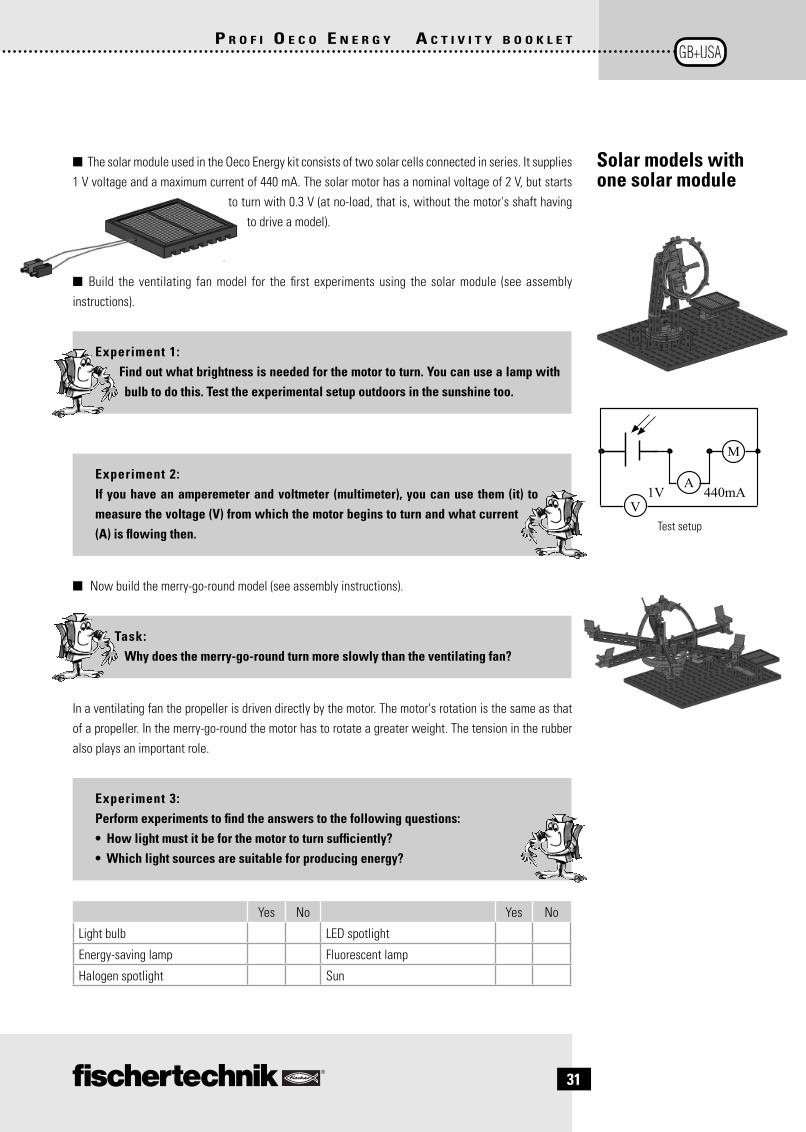
■ The solar module used in the Oeco Energy kit consists of two solar cells connected in series. It supplies 1 V voltage and a maximum current of 440 mA. The solar motor has a nominal voltage of 2 V, but starts
to turn with 0.3 V (at no-load, that is, without the motor's shaft having to drive a model).
■ Build the ventilating fan model for the fi rst experiments using the solar module (see assembly instructions).
Experiment 1:Find out what brightness is needed for the motor to turn. You can use a lamp with bulb to do this. Test the experimental setup outdoors in the sunshine too.
Experiment 2:If you have an amperemeter and voltmeter (multimeter), you can use them (it) to measure the voltage (V) from which the motor begins to turn and what current (A) is fl owing then.
■ Now build the merry-go-round model (see assembly instructions).
Task:Why does the merry-go-round turn more slowly than the ventilating fan?
In a ventilating fan the propeller is driven directly by the motor. The motor's rotation is the same as that of a propeller. In the merry-go-round the motor has to rotate a greater weight. The tension in the rubber also plays an important role.
Experiment 3:Perform experiments to fi nd the answers to the following questions:• How light must it be for the motor to turn suffi ciently?• Which light sources are suitable for producing energy?
Yes No Yes No
Light bulb LED spotlight
Energy-saving lamp Fluorescent lamp
Halogen spotlight Sun
Solar models with one solar module
V
A
M
1V 440mA
Test setup
2 OecoEnergy_GB_2.Aufl.indd 312 OecoEnergy_GB_2.Aufl.indd 31 22.01.2014 15:19:1822.01.2014 15:19:18

32
P R O F I O E C O E N E R G Y A C T I V I T Y B O O K L E T
■ Two solar modules connected in parallel produce more current at the the same voltage. You need this circuit for the new solar cyclist model (see operating instructions).
Experiment 1:If you have a multimeter, you can use it to measure the voltage and current supplied by the parallel connection.
Experiment 2:Test the parallel connection by installing one solar module and then two in the model.
■ Now build the Ferris wheel as the next model (see assembly instructions). Here too, you use two solar modules connected in parallel.
Experiment 3:Repeat experiments 1 and 2 with this model too.
Both models have the same mechanical setup. The solar modules are connected to the solar motor. If light shines on the modules the solar motor begins to rotate. The rotary disk (Ferris wheel), which is fastened onto the axis of the Ferris wheel, is rotated by a belt. In the case of the solar cyclist this occurs via the spoke wheel at the cyclist's feet.
Experiment 4:Take a closer look at the models' drives, what can you see?
In the case of the solar cyclist the spoke wheel is driven directly by the motor via a belt. By contrast, the Ferris wheel is driven by a worm drive with connected gear wheel and only then by the belt. The result of this is that the Ferris wheel turns more slowly.
Solar models with two solar modules
Parallel connection
V
A
M
1V 880mA
Test setup
2 OecoEnergy_GB_2.Aufl.indd 322 OecoEnergy_GB_2.Aufl.indd 32 22.01.2014 15:19:1822.01.2014 15:19:18

33
P R O F I O E C O E N E R G Y A C T I V I T Y B O O K L E T
Solar models with two solar modules
Series connection
Solar vehicle
V
AM
1V440mA
Test setup
V V1V
2V
1V
0V
1
2
3
1
2
3Pushbutton
■ Solar vehicles get most of their propulsion energy directly from the sun. The surface of the vehicles is equipped with solar cells, which convert the solar power on the vehicle into electric current. As electric cars, they frequently also carry an energy store (mostly accumulators) with them, so that they can stay roadworthy even in poor light conditions or cloud cover, at least for a limited time.
■ The principle of solar cells connected in series should be used for the solar vehicle, i.e. more voltage with the same current. Build the model as described in the assembly instructions and wire it as described in the circuit diagram.
In this model you are introduced to a new component, the pushbutton switch. Pushbutton switches belong to the category of touch sensors. If you press the red button, a contact in the casing is switched (moved) mechanically and a current fl ows between contacts 1 and 3. At the same time the switch circuit between contact points 1 and 2 is interrupted.
Pushbutton switches or switches are used in two different ways:
Pushbutton switch as a "normally open contact"The two circuit diagrams show you the experiment setup. The positive terminal (pole) of the solar module is connected to contact 1 of the pushbutton switch, and the solar motor is connected to contact 3 of the pushbutton switch and to the negative terminal (pole) of the solar module. If the pushbutton switch is not pressed then the motor is switched off. If you press the pushbutton switch, the electric circuit is closed via contact 1 and contact 3, and the motor runs.
What is the function of the pushbutton switch? If sunlight shines on the solar cell and the pushbutton is pressed, the worm drive of the solar motor begins to turn and sets the gear wheel in motion.
Experiment 1:Find out what brightness is needed for the vehicle to travel.
Experiment 2:Test the effect of the light intensity on the vehicle's speed. How much time does the vehicle need to travel a distance of one meter?
0V
1V
1
2
3
2 OecoEnergy_GB_2.Aufl.indd 332 OecoEnergy_GB_2.Aufl.indd 33 22.01.2014 15:19:1922.01.2014 15:19:19

34
P R O F I O E C O E N E R G Y A C T I V I T Y B O O K L E T
■ A vehicle which runs on "solar electricity" is not automatically a solar vehicle. If a vehicle, for example, only "refuels" its electricity at a solar charging station, the electricity is produced from sunlight, but the vehicle itself is an electric vehicle.
Convert the solar vehicle model into the electric vehicle and the build the solar charging station model (see assembly instructions). To do this, you have to remove the solar modules from the solar vehicle.
■ During your experiments with the solar modules you probably found that this form of energy production has a disadvantage. The models stop as soon as they are outside the range of the light source or are in the shade. It is therefore important to equip the models with an energy store for this period; the energy store is charged with solar power.
■ The Goldcap in the kit is just such an energy store. It consists of two pieces of activated carbon, which are only separated by a thin insulating layer. The characteristic feature of the Goldcap is its extremely high capacity. The capacitor used by you has a capacity of 10 F (farad). You can use the Goldcap like a small rechargeable battery. The advantage of the Goldcap over a rechargeable battery is that the Goldcap can be charged very quickly, it cannot be overcharged and it cannot be over-discharged.
Caution, danger of explosion!Never connect the Goldcap to a voltage higher than 3 V, otherwise there is a risk of explosion! This means the Goldcap must never be connected to a usual 9 V fi schertechnik power supply.
When installing the plugs on the Goldcap, you must make sure the polarity of the plugs is correct (connect green plug to minus). It is advisable to cut the two connections of the Goldcap to the same length.
"Fuel" the electric vehicle - by connecting it to the solar charging station. If there is suffi cient light energy the Goldcap is charged. Once it is charged (LED lights up), connect the Goldcap to the solar
motor. If you press the pushbutton switch the vehicle starts to move.
* Despite the name, there is unfortunately no gold in it! Goldcap is a product name which the manufacturer has given the special capacitor.
Goldcap energy store
Store electric energy
Electric vehicle with solar charging station
Goldcap*
2 OecoEnergy_GB_2.Aufl.indd 342 OecoEnergy_GB_2.Aufl.indd 34 22.01.2014 15:19:1922.01.2014 15:19:19

35
P R O F I O E C O E N E R G Y A C T I V I T Y B O O K L E T
Experiment 1:If you have a measuring device, you can measure the voltage at the Goldcap* while it is charging. You can also see how far the charging process has progressed.
Experiment 2:• See how long the car runs with on a "full tank".• What speed does it reach?
What is the function of the LED in the solar station? It acts as a charge indicator. If the Goldcap is fully charged, the LED lights up.
■ Inverse-parallel – what does this mean? It simply means that two solar modules are connected in parallel so that the plus pole of one solar module is connected to the minus pole of the other solar module. How does this circuit behave when light shines on it?The diagram should show you clearly what happens. In the situation shown in the middle the sun shines on both solar modules with the same light intensity, so that the voltages of the two solar modules cancel each other out and the meter displays 0V. If one solar module is blacked out, or put in the shade, only the illuminated module produces current and the meter moves in the corresponding direction.
You will apply this principle in your next two models.
Inverse-parallel connection
2 OecoEnergy_GB_2.Aufl.indd 352 OecoEnergy_GB_2.Aufl.indd 35 22.01.2014 15:19:2022.01.2014 15:19:20
36
P R O F I O E C O E N E R G Y A C T I V I T Y B O O K L E T
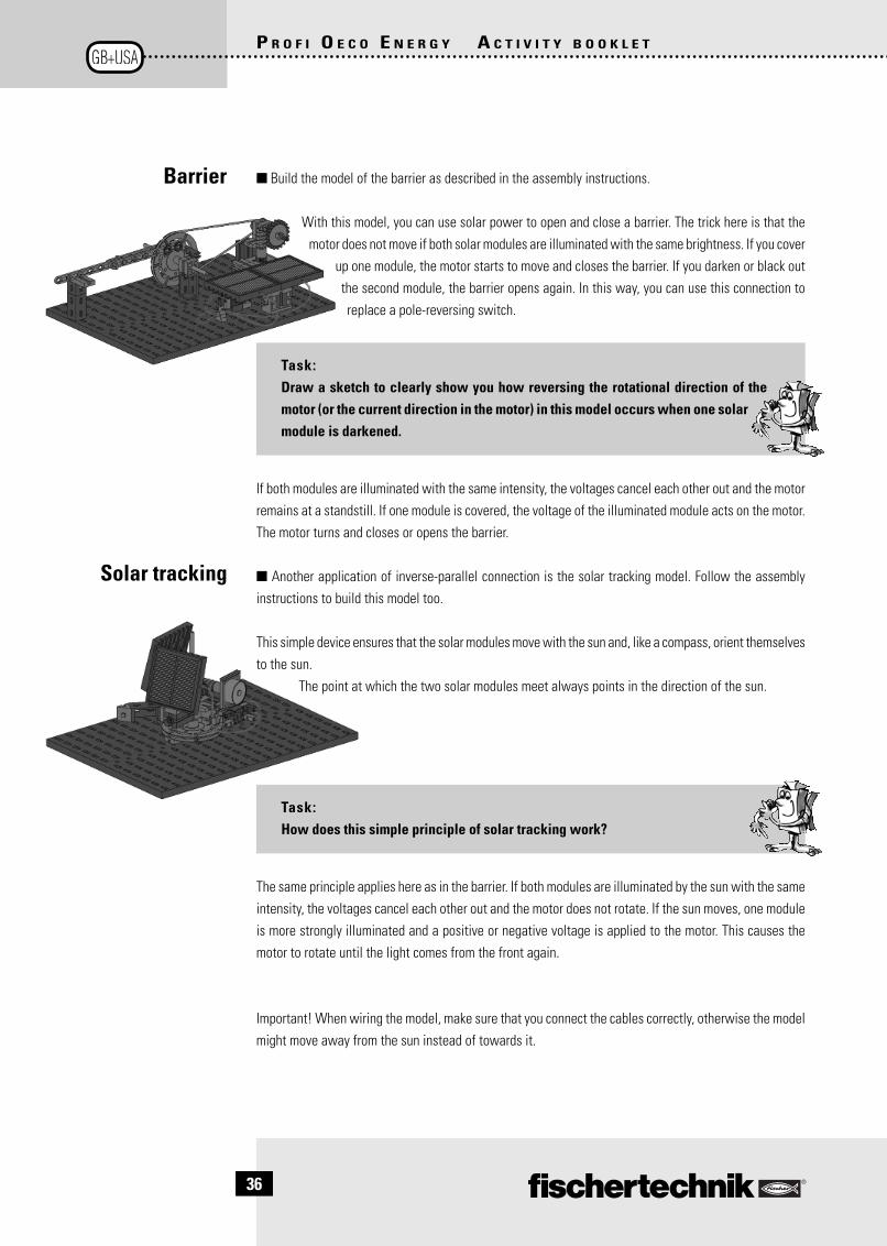
Barrier ■ Build the model of the barrier as described in the assembly instructions.
With this model, you can use solar power to open and close a barrier. The trick here is that the motor does not move if both solar modules are illuminated with the same brightness. If you cover
up one module, the motor starts to move and closes the barrier. If you darken or black out the second module, the barrier opens again. In this way, you can use this connection to replace a pole-reversing switch.
Task:Draw a sketch to clearly show you how reversing the rotational direction of the motor (or the current direction in the motor) in this model occurs when one solar module is darkened.
If both modules are illuminated with the same intensity, the voltages cancel each other out and the motor remains at a standstill. If one module is covered, the voltage of the illuminated module acts on the motor. The motor turns and closes or opens the barrier.
■ Another application of inverse-parallel connection is the solar tracking model. Follow the assembly instructions to build this model too.
This simple device ensures that the solar modules move with the sun and, like a compass, orient themselves to the sun.
The point at which the two solar modules meet always points in the direction of the sun.
Task:How does this simple principle of solar tracking work?
The same principle applies here as in the barrier. If both modules are illuminated by the sun with the same intensity, the voltages cancel each other out and the motor does not rotate. If the sun moves, one module is more strongly illuminated and a positive or negative voltage is applied to the motor. This causes the motor to rotate until the light comes from the front again.
Important! When wiring the model, make sure that you connect the cables correctly, otherwise the model might move away from the sun instead of towards it.
Solar tracking
2 OecoEnergy_GB_2.Aufl.indd 362 OecoEnergy_GB_2.Aufl.indd 36 22.01.2014 15:19:2022.01.2014 15:19:20

37
P R O F I O E C O E N E R G Y A C T I V I T Y B O O K L E T
Eco-house■ In the next task you bring together all that you have found out so far about energy sources. As the picture shows, the homeowner has used different renewable energy sources. We call our mode (see assembly instructions) - an eco-house. This energy production reduces the costs for heating and electrical power.
Task:Find out on the internet about different kinds of regenerative or renewable energy production.
The LED installed in the model represents the individual consumers of electricity (loads) such as lights, TVs and many more appliances.
Task 1:First of all, the LED is supplied electricity from the wind power station.
Wire up the electrical components as described in the assembly instructions. The disadvantage of this circuit is that the LED does not light up if there's no wind.
Task 2:In this task the LED gets its electricity from the solar cells.
Wire up the electrical components as described in the assembly instructions. The disadvantage of this circuit is that the LED does not light up if there's no solar power available.
Task 3:In this task the wind and solar power are combined. The Goldcap acts as an energy store.
Wire up the electrical components as described in the assembly instructions. With this circuit you compensate for the disadvantages found in the previous two tasks.
If the wind is blowing (mini-switch is not pressed) the house is supplied with electricity from wind power. The LED lights up. At the same time, the Goldcap is charged by the solar system.
If there is no wind, the mini-switch is pressed. The LED is now supplied with solar power via the Goldcap.
2 OecoEnergy_GB_2.Aufl.indd 372 OecoEnergy_GB_2.Aufl.indd 37 22.01.2014 15:19:2022.01.2014 15:19:20

38
P R O F I O E C O E N E R G Y A C T I V I T Y B O O K L E T
Fuel cell
preview
What to do if something doesn't work?
Mechanical fault • Ensure that the movable components move smoothly and easily.
• Are the components installed as described in the instruc-tions?
Electrical fault • LED does not light up – check for correct polarity.• The motor's direction of rotation – correct polarity?• Goldcap does not charge – correct polarity?• Pushbutton – check that it is connected properly 1,2,3• Solar module does not produce any voltage – wrong light
source?
Energy supplier for solar module • Sun, halogen lamp, light bulb.• Not an energy-saving lamp or LED lamp!
Yardstick for light energy 100 W light bulb at a distance of approximately 40 cm. The motor without a connected load rotates.
■ Apart from the renewable energy sources introduced in this kit, the supplementary Fuel Cell kit provides a real highlight when it comes to renewable energy – the fuel cell. You can use this energy source to run models from the Oeco Energy kit, as well as other technically interesting models.
2 OecoEnergy_GB_2.Aufl.indd 382 OecoEnergy_GB_2.Aufl.indd 38 22.01.2014 15:19:2122.01.2014 15:19:21

39
P R O F I O E C O E N E R G Y + F U E L C E L L K I T A C T I V I T Y B O O K L E T
Experiments with the Oeco Energy + Fuel Cell Kit P. 40
Ventilating fan P. 40Fuel cell vehicles P. 41Solar station P. 41Fuel cell vehicle with solar station P. 41Electric vehicle with solar station P. 42Solar vehicle with three solar modules P. 42Enhanced eco-house with three solar modules P. 43
Parallel connection of fuel cell and solar modules P. 43 Pump P. 43
Contents
Profi Oeco Energy
+ Fuel Cell Kit
2 OecoEnergy_GB_2.Aufl.indd 392 OecoEnergy_GB_2.Aufl.indd 39 22.01.2014 15:19:2122.01.2014 15:19:21
40
P R O F I O E C O E N E R G Y + F U E L C E L L K I T A C T I V I T Y B O O K L E T
Experiments with the Oeco Energy + Fuel Cell Kit
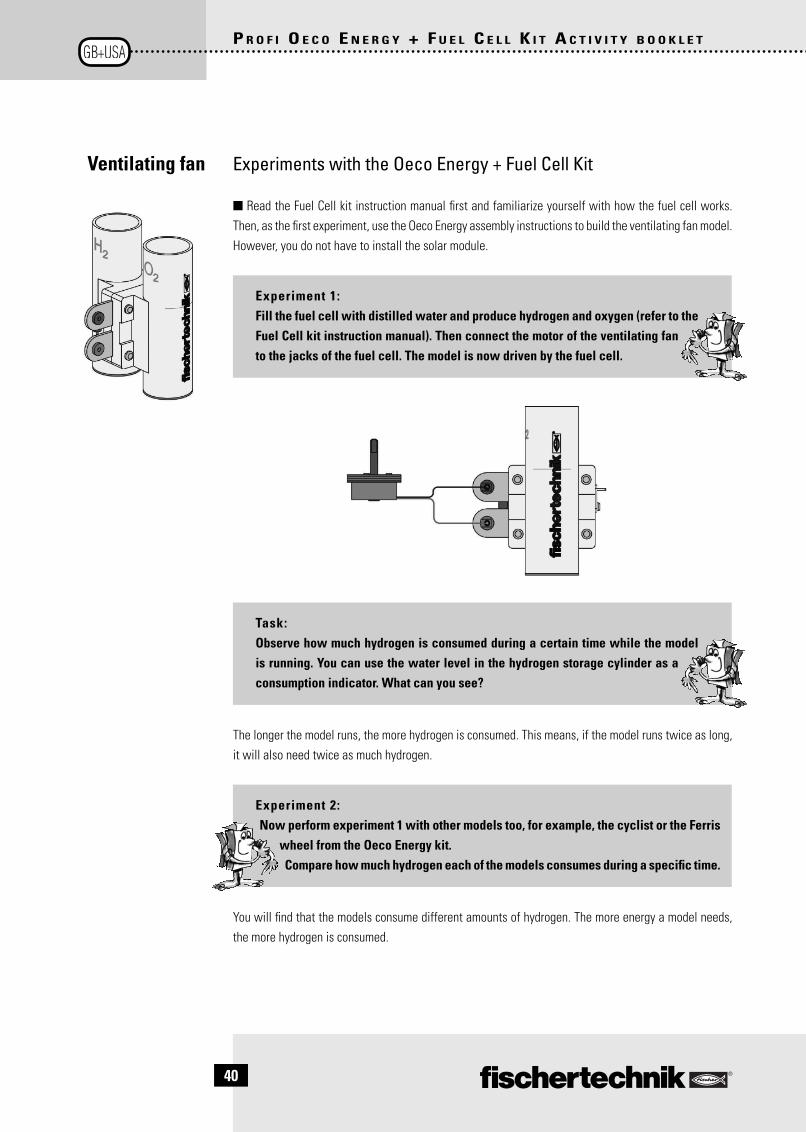
■ Read the Fuel Cell kit instruction manual fi rst and familiarize yourself with how the fuel cell works. Then, as the fi rst experiment, use the Oeco Energy assembly instructions to build the ventilating fan model. However, you do not have to install the solar module.
Experiment 1:Fill the fuel cell with distilled water and produce hydrogen and oxygen (refer to the Fuel Cell kit instruction manual). Then connect the motor of the ventilating fan to the jacks of the fuel cell. The model is now driven by the fuel cell.
Task:Observe how much hydrogen is consumed during a certain time while the model is running. You can use the water level in the hydrogen storage cylinder as a consumption indicator. What can you see?
The longer the model runs, the more hydrogen is consumed. This means, if the model runs twice as long, it will also need twice as much hydrogen.
Experiment 2:Now perform experiment 1 with other models too, for example, the cyclist or the Ferris
wheel from the Oeco Energy kit.Compare how much hydrogen each of the models consumes during a specifi c time.
You will fi nd that the models consume different amounts of hydrogen. The more energy a model needs, the more hydrogen is consumed.
Ventilating fan
2 OecoEnergy_GB_2.Aufl.indd 402 OecoEnergy_GB_2.Aufl.indd 40 22.01.2014 15:19:2122.01.2014 15:19:21

41
P R O F I O E C O E N E R G Y + F U E L C E L L K I T A C T I V I T Y B O O K L E T
■ Fuel cell vehicles are means of transportation with an electric drive, in which a fuel cell is used to produce the required electrical power from hydrogen or methanol as energy sources. This form of propulsion is still considered to be experimental by most people and current development is in competition with battery-powered electric drives; nevertheless, series production of the fi rst vehicles began in 2008.
Problems with the range and the economic effi ciency of the rechargeable batteries (price and life) have resulted in several car manufacturers favoring the fuel cell as the technology of the future at the present time. However, development of the infrastructure for the hydrogen production, hydrogen storage and refueling is essentially still open.
■ You have already built and started up a solar charging station with the OECO ENERGY kit. For the next models this is extended with a third solar module. These are connected in series, as shown in the circuit diagram, and therefore supply a higher voltage
Build the solar station model as described in the assembly instructions.
Experiment 1:Test the time it takes for the fuel cell to charge with one, two and three solar modules.
1 module 2 modules 3 modules
Time
■ Build the fuel cell vehicle in addition to the solar station.
Experiment 2:Fill the fuel cell with distilled water and connect it to the station's solar modules, in
order to produce hydrogen and oxygen.Experiment with the fuel cell vehicle.
• How much hydrogen does the fuel cell consume in a certain time?• What distance can be covered with a "full tank"?• When does the vehicle run longer on a full tank – when it travels straight ahead or
when it travels in a circle?
The longer the vehicle runs, the more hydrogen is consumed. When the vehicle travels around a tight curve, the motor needs more energy than when the vehicle travels straight ahead. Therefore, more hydrogen is also consumed when the vehicle travels in a circle.
Solar station
Fuel cell vehicle with solar station
Fuel cell vehicles
2 OecoEnergy_GB_2.Aufl.indd 412 OecoEnergy_GB_2.Aufl.indd 41 22.01.2014 15:19:2222.01.2014 15:19:22

42
P R O F I O E C O E N E R G Y + F U E L C E L L K I T A C T I V I T Y B O O K L E T
Electric vehicle with solar station
■ In the next experiment you combine the solar station with the "electric vehicle" model. Install the LED in the solar station as a charge indicator.
Experiment:Test the effect of three solar modules on the charge time of the Goldcap. How much time does the vehicle need to travel a distance of 1 meter?
Important! When the LED used as a solar station charge indicator begins to light up, the Goldcap is not yet fully charged. Leave the vehicle connected to the solar station for about another 2 minutes. The higher charging voltage of the three solar modules charges the Goldcap signifi cantly more than with 2 solar modules. You will therefore notice that the vehicle can travel much faster and further.
■ The difference between the parallel connection and series connection of solar modules is that in the parallel connection the voltage remains the same but more current is supplied than with one module. In the series connection the current remains the same and instead the voltage of the two solar modules is added together. You use the series connection for your experiments.
■ Build the solar vehicle model with 3 solar modules (see assembly instructions). As the Oeco Energy kit only contains two modules, use the module from the Fuel Cell kit too. You can use the solar vehicle to
perform the following experiments on the series connection of solar modules.
Experiment 1:Test which light intensity is needed for the vehicle to travel. Perform this experiment with one, two and three solar modules.
By connecting the modules in series, their voltages are added together. 3 modules therefore supply approximately 3 V.
Experiment 2:Test the effect of the light intensity on the vehicle's speed. How much time does the vehicle need to travel a distance of one meter?
Experiment 3:Test the effect of the surface conditions (carpet, wooden fl ooring, etc.) on the vehicle's speed. How much time does the vehicle need to travel a distance of one meter?
Solar vehicle with three solar modules
2 OecoEnergy_GB_2.Aufl.indd 422 OecoEnergy_GB_2.Aufl.indd 42 22.01.2014 15:19:2222.01.2014 15:19:22

43
P R O F I O E C O E N E R G Y + F U E L C E L L K I T A C T I V I T Y B O O K L E T
A third solar module is added to the eco-house from the Oeco Energy kit.
■ Use the Oeco Energy assembly instructions to build the enhanced eco-house.
Experiment :Test what effect the third solar module has on
the eco-house. How long does it take for the Goldcap to charge and discharge?
Charge time
Discharge time
■ For the following experiments, build the solar pump with fuel cell model (see Oeco Energy assembly instructions).
The fuel cell is installed parallel with the solar modules. In this way it is charged while the solar pump is running.
Experiment 1:Check the working speed of the pump with 2 and 3 solar modules.What do you observe?
The more solar modules connected in series, the higher the voltage at the motor. The motor therefore runs faster.
Experiment 2:Cover up the solar modules, so that they do not supply any voltage. Observe the solar pump.
The pump continues running, because it is now drawing voltage from the fuel cell.
Parallel connection of fuel cell and solar modules
Pump
Enhanced eco-house
with 3 solar modules
2 OecoEnergy_GB_2.Aufl.indd 432 OecoEnergy_GB_2.Aufl.indd 43 22.01.2014 15:19:2222.01.2014 15:19:22

44
P R O F I O E C O E N E R G Y + F U E L C E L L K I T A C T I V I T Y B O O K L E T
Experiment 3:Fill the fuel cell with distilled water and place the model in the sunlight or illuminate
the solar modules with a suitable light source (e. g. 100 W light bulb at a distance of 30 cm).
What do you observe?
The pump moves and at the same time, hydrogen and oxygen are produced in the fuel cell. The motor and the fuel cell are connected in parallel.
Experiment 4:Now wait until a certain quantity of hydrogen has been produced and then cover up the solar modules or switch off the light source.
What can you observe now? Pay attention to the hydrogen storage cylinder too.
The model runs more slowly, but it does not stop. The fuel cell consumes hydrogen.If the light intensity reduces, the model is driven by the fuel cell. The pump now continues running, even after sunset or if the sun is concealed by a cloud. The reason why the model now runs more slowly is that the fuel cell supplies a lower voltage than the solar modules. An electric motor rotates more slowly if it is supplied with a lower voltage.
What to do if something doesn't work?
Mechanical fault • Ensure that the movable components move smoothly and easily.• The components are not installed as described in the instructions.
Electrical fault • Fuel cell does not supply any current – check the water level, did you use distilled water?
• Solar module does not supply any current – wrong light source?
Further information on the fuel cell is provided in the Fuel Cell Kit instruction manual
2 OecoEnergy_GB_2.Aufl.indd 442 OecoEnergy_GB_2.Aufl.indd 44 22.01.2014 15:19:2322.01.2014 15:19:23

146
406
· 01/
14 ·
Co ·
Prin
ted
in G
erm
any
· Tec
hnis
che
Ände
rung
en v
orbe
halte
n ·
Subj
ect t
o te
chni
cal m
odifi
catio
n
Impressum
Satz und Layout:ido Redaktionsbüro
Text:Hermann Weininger
Copyright: 2013 fi schertechnik GmbH
0 Oeco Energy U2+3 .indd 30 Oeco Energy U2+3 .indd 3 22.01.2014 11:08:4822.01.2014 11:08:48
