profi mechanics and statics - fischertechnik
TRANSCRIPT

Profi Mechanics und Statics Introduction
Name
Class Sheet No.
General Machines are found in all areas of our lives. Who carries heavy loads around today? Who drills a hole in the wall with pure muscle power? Who still washes his clothes on a washboard? Almost nobody. The human being has invented many devices to make his work and his life easier. This began with the historical mill work, which was driven by waterpower, for a mill and progressed through the jet engines for a jumbo jet onwards to the recording of data in pixels and making them visible. Devices that make your work easier or even do it for you are called machines in the technical language.
Your Task • Machines can perform various work. Assign the machines from the list
to the work they can do.
Machines can This machine can Move loads
Process materials
Transform electrical energy into kinetic energy
Process data
Truck, car, crane, excavator, electric motor, dough mixing machine, cement mixer, blender, pocket calculator, computer

Profi Mechanics und Statics Introduction
Name
Class Sheet No.
General Mechanics deals with the effects and forces, which influence rigid and moving bodies. Mechanics is divided into the areas of _______________, __________, _______, ________ and many others. We will limit ourselves to the areas of dynamics and statics. Even in the ancient world, scientists attempted to explore the various areas of mechanics. The old master builders of cathedrals built higher and higher churches that pushed the experimentation with the balance of forces to its limits. Today, a structural engineer does the calculations for the stability of a building or design. His profession comes from the subarea of mechanics called statics. You will learn more about this in the statics part. When a machine, a gear unit or another device is placed in motion, it is dynamic. Dynamics is another subarea of mechanics and describes, in contrast to statics, the change in the movement variables such as the rotation of a shaft, a back-and-forth movement or transmission by a toothed gear. Thus, dynamics is the science of changes in movement. You will learn about this part of mechanics in the following chapters.

Profi Mechanics und Statics Introduction
Name
Class Sheet No.
General A motor is a possible drive for a machine. There are two types of motors: The combustion motor and the electric motor. For example, a car is driven by a combustion motor. Of course, you don't have such a complicated motor in your building set, but you do have an electric motor, which we will call the e-motor for short. Electric motors are the drives for most of the machines in your life. They can be used anywhere where electrical energy is available and in the meantime that is possible at about any location on earth. The electric motor in your building set has a very high number of revolutions per minute (RPM), which means that it rotates so fast that you cannot even see one single revolution. But your motor is very "weak," which means that it cannot lift loads and cannot drive any vehicle. To reduce the fast revolutions and the make the motor "stronger," you need a gear unit.

Profi Mechanics And Statics Gear Unit
Name
Class Sheet No.
General A worm gear pair is best suited to reduce the high speed of the motor, To do this, a worm gear is placed on the motor shaft, that is the rod, which extends out of the motor casing. The worm gear drives a toothed gear. This type of gear unit is used where high revolutions per minute are to be reduced in a small area. A worm gear works in a self-locking manner, which means that the worm gear can be driven by the worm gear pair, but in the other direction it locks the gear unit. Bar barriers and cranes use this gear unit because here the safe locking of the worm gear keeps the bar barrier or the attached load from "reversing" the drive. Your Task
• Build a copy of the bar barrier model.
• Rotate the bar barrier upwards with the crank. How many times do you have to turn the crank to put the bar barrier in a vertical position? Enter the results in the table.
Number or revolutions until the bar barrier is vertical.

Profi Mechanics And Statics Gear Unit
Name
Class Sheet No.
• Now try to pull the bar barrier downwards with your fingers. What do you notice?
........................................................................................................................................................................................................................................................................................................................................................................................................................................................................................................ Solution Of course, you had to turn the crank a few times to move the bar barrier 90°. Were you able to pull the bar barrier down? See, that is how a self-locking gear unit works. With the small crank, you could easily lift the big bar barrier so you increased the driving force with the worm gear pair. The worm gear pair has many advantages:
• It saves space. • It reduces the revolutions per minute of the drive many times. • It is irreversible. • It increases the force of the drive. • But, it also changes the direction of rotation of the drive.
pull

Profi Mechanics And Statics Gear Unit
Name
Class Sheet No.
General The mechanism of the worm gear is used in a lot of machines. A simple example for the use of a worm gear pair is the turntable. For the gear unit shown here, the speed is to be reduced, the direction of rotation is to be changed and the resistance of the loaded turntable must not be allowed to stop the motor. Your Task
• Build a copy of the turntable. • Put a pot with water or earth in it on the turntable plate. Caution! Of
course, only use a pot that fits on the plate. • Observe the pot. Can the little motor really rotate the big pot? • Describe your observations. • Name the components in the construction drawing of the turntable.
Observations ..................................................................................................................................................................................................................................................................................................................................................................................................................................................................................................................................................................................................................................
Profi Mechanics And Statics Gear Unit
Name
Class Sheet No.
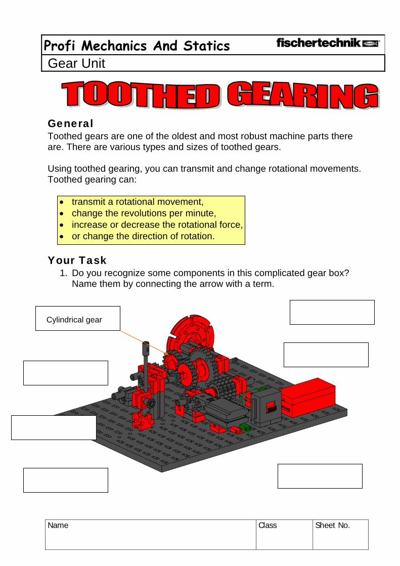
General Toothed gears are one of the oldest and most robust machine parts there are. There are various types and sizes of toothed gears. Using toothed gearing, you can transmit and change rotational movements. Toothed gearing can:
• transmit a rotational movement, • change the revolutions per minute, • increase or decrease the rotational force, • or change the direction of rotation.
Your Task
1. Do you recognize some components in this complicated gear box? Name them by connecting the arrow with a term.
Cylindrical gear

Profi Mechanics And Statics Gear Unit
Name
Class Sheet No.
General In the following models, you will build toothed gearing with straight teethed cylindrical gears. Cylindrical gears are always used if the rotational motion is to be transmitted to a parallel shaft. Your Task
• Build a copy of the crank gear 1. • Turn the crank one time. How often does the shaft with the second
toothed gear turn. • Turn the crank clockwise. What direction does the driven gear turn and
so the second shaft? Draw it in.
Revolutions toothed gear 1
Revolutions toothed gear 2
Revolutions toothed gear 1
Revolutions toothed gear 2

Profi Mechanics And Statics Gear Unit
Name
Class Sheet No.
Solution If you want to move a vehicle in this way, you will certainly go very slow and you would also go backwards. However, this model shows you very simply how to build a gear unit and make the calculation for the gear unit. Calculation of the transmission ratio for the toothed gearings Drive gear Driven gear Gear No. 1 2 No. of teeth on a toothed gear
Z1 Z2
Number of revolutions n1 n2 Direction of rotation (left, right)

Profi Mechanics And Statics Gear Unit
Name
Class Sheet No.
General Your Task
• Build a copy of the crank gear 2. • Make a mark on each toothed gear at the top. • Turn the crank one time? How often does the shaft with the second
tooted gear turn? Record this in the table. • Turn the crank clockwise. What direction does the driven gear turn and
so the second shaft? Draw the direction of rotation in the figure.

Profi Mechanics And Statics Gear Unit
Name
Class Sheet No.
Solution If you would move a vehicle in this way, you would move somewhat faster than with your first model. Calculate the transmission ratio for this gear unit as well. Calculation of the transmission ratio for the toothed gearings Drive gear Driven gear Gear No. 1 2 No. of teeth on a toothed gear
Z1 Z2
Number of revolutions n1 n2 Direction of rotation (left, right)

Profi Mechanics And Statics Gear Unit
Name
Class Sheet No.
General In order to use your experience with gear units in a motor-driven model, build vehicle 1, construction instructions p. 13-15. The motor rotates many times faster than your hand. With the help of the motor and the gear unit, you now have a real vehicle drive.
So that the motor-driven vehicle can go even faster, build vehicle 2 (construction instructions p. 16-17). Now your mobile travels ..... times as fast as the one before. But this transmission ratio has its problems on a mountain.
Vehicle 3 has a "reversed" gear unit construction compared to vehicle 2. How does the speed of this vehicle change in comparison to the other two models? First think about it and then write in your ideas before you build vehicle 3 (construction instructions p. 18). ............................................. ............................................. ............................................. ............................................. ............................................. ............................................. ............................................. ............................................. .............................................
Profi Mechanics And Statics Gear Unit
Name
Class Sheet No.
Your Task How does the speed of the vehicles change? Summarize the results for the three models. ................................................................................................................................................................................................................................................................................................................................................................................................................................................................................................................................................................................................................................................................................................................................................................................................................................................................................................................................................................................................................................................................................................................................................................................................................................................................... .......................................................................................................................... .......................................................................................................................... .......................................................................................................................... .......................................................................................................................... .......................................................................................................................... Solution With the three toothed gearings, you have created one with a transmission ratio of 1:1 with the same revolutions per minute and the same torque. Your second model has a transmission ratio of 1:1.5 and a reduced torque and this means faster but less "force." Vehicle 3 has a transmission ratio of 2:1 and thus goes slower than the other two and that's why this is called a reduction ratio. This type of transmission has the advantage that it is "stronger," meaning it has a higher torque. This effect is used, for example, with a tractor. If travels slower than a car of course, but it has lots more power.

Profi Mechanics And Statics Gear Unit
Name
Class Sheet No.
General If there is a greater distance between two shafts, then gear unit technology uses tension gear units to span this distance. Belts or chains are used as the tension medium and they connect the drive gears and the driven gears over longer distances with each other by keeping the machine parts in a certain interaction. You know transmission ratios from your bicycle gears. Here you are also driving a large gear pinion in the front and a small gear pinion in the rear to be able to go faster on the level and on a mountain you certainly change to a smaller transmission ratio such as 1.1 or when it is really steep to 2:1. Your Task
• Build the vehicle with a chain drive (p. 19-20). Calculation of the transmission ratio for the toothed gearings Drive gear Driven gear Gear No. 1 2 No. of teeth on a toothed gear
Z1 Z2
Number or revolutions n1 n2 Direction of rotation (left, right)

Profi Mechanics And Statics Gear Unit
Name
Class Sheet No.
Solution You also have such a gear unit on your bicycle. The distance between the pedal drive and the rear wheel is spanned by a chain. On a mountain bike or a racing bike, of course you have not only one gear, but you can choose from many gears. This means that you adjust your speed depending on the force needed and the force to be transmitted and the revolutions per minute. In this case, the toothed gears are not called cylindrical gears, but chain sprockets. This is exactly how the transmission is done with a moped or motorcycle. Be inventive and build your own motorcycle from your fischertechnik parts.

Profi Mechanics And Statics Gear Unit
Name
Class Sheet No.
General The last models showed you how important the right toothed gear ratio is for the various vehicle types and speeds. So that you don't have to run after your vehicle because it always travels in a straight line, it is now going to get steering.
Your Task • Build the vehicle model with steering (p. 21-23). • Name the components in the model drawing with the help of the three
figures. To do this, connect the terms in the figures with the components in the model drawing.
Pivot pin
Axle
Pivot support Steering wheel Steering column
Tongue

Profi Mechanics And Statics Gear Unit
Name
Class Sheet No.
Solution This steering is the simplest and thus the oldest that human beings have developed. The type of steering is called fifth-wheel steering. The Celts developed a system for their wagons to make the front axle and thus the vehicle steerable. They invented the fifth-wheel steering, which is primarily still used today in the area of trailers, hand carts and horse-drawn wagons. The fifth-wheel steering is a steering system with a bolster-like carrier for the axle and the wheels. This is attached to a rotatable pin in the wagon structure such as the base plate or the chassis. The steering system can be controlled either through a pivot pin as a steering column or with a rod, which is the tongue of the wagon, which is attached to the swiveling bolster. In a soap box, the fifth-wheel steering can be operated with your feet or with two ropes.

Profi Mechanics And Statics Gear Unit
Name
Class Sheet No.
General
• With the previous models, you became familiar with some toothed gear transmission ratios. With the following construction, you expand the simple toothed gear transmission with a gear unit with several gears. A gear unit such as in an automobile, a drill or a moped. This model has a compound gear unit, which means a gear unit, which consists of more than just two toothed gears. With this, you are experimenting with the transmission effect of toothed gears and pairs of toothed gears placed in a series one after the other.
Your Task 1st Gear 2nd Gear 3rd Gear
• Build a copy of the gear unit (p. 24-28). • Turn the motor on and move the "gear shift lever" slowly from gear 1 to
gear 3. Insure that the toothed gears of both shafts are in one line. • Write down your observations.
Observations of the individual gears Gear No. 1 2 3 Observation faster, slower
Direction of rotation same, opposite

Profi Mechanics And Statics Gear Unit
Name
Class Sheet No.
Solution This gear unit in gear 3 goes in a different direction than in gear 1 and gear 2. This is because that here three toothed gears are in a series. When an uneven number of toothed gears are in a series, then the driven gear has the same direction of rotation as the drive gear. This effect is used for a car to drive backwards. Possible Additions Your Task
• Give it a try. Build your own model with different numbers of toothed gears in a series.
• Replace the turntable with a winding drum and you now have a cable winch like on a crane for various heavy loads.
• Can you put more gears into your gear unit? Experiment with the toothed gears in your fishchertechnic building set.
• Expert task: Build a gear unit with a chain.
Profi Mechanics And Statics Gear Unit
Name
Class Sheet No.
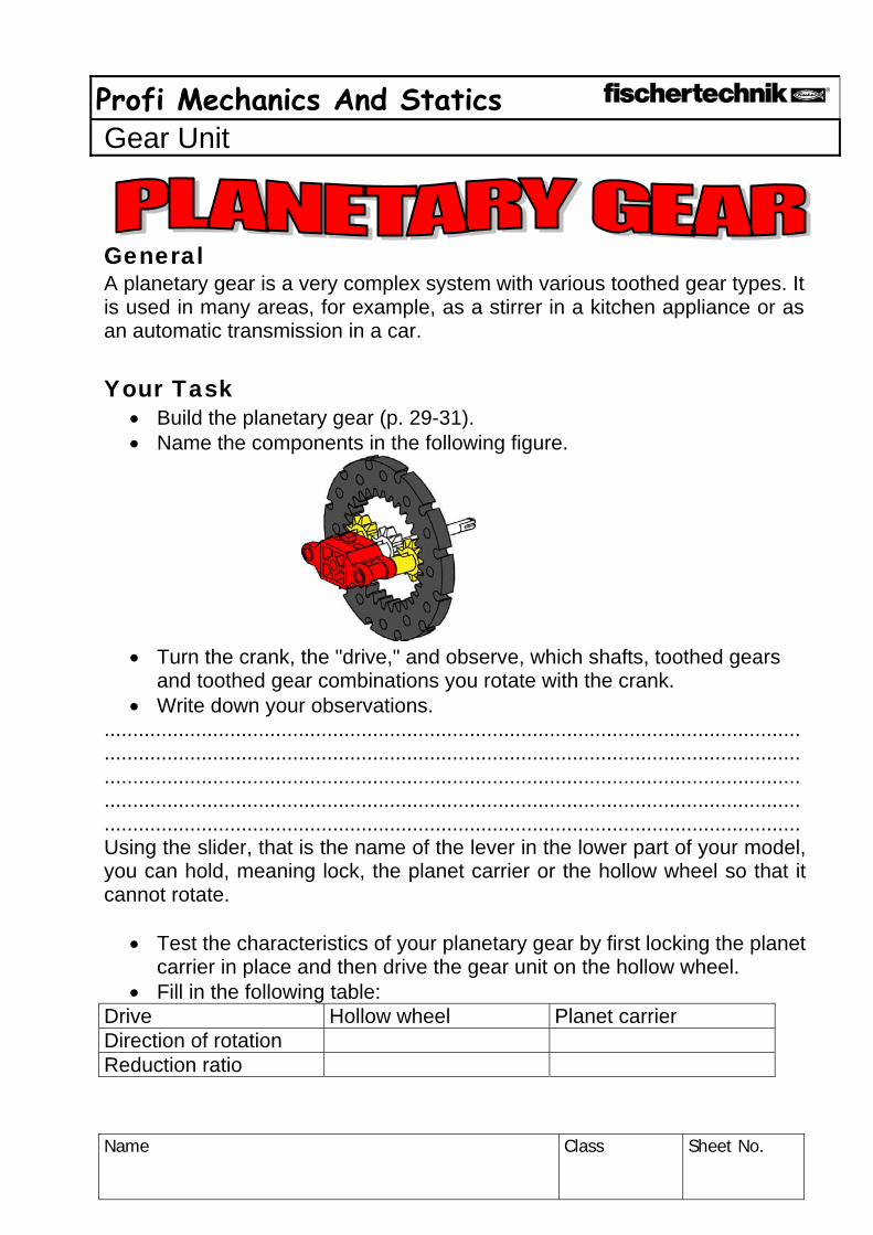
General A planetary gear is a very complex system with various toothed gear types. It is used in many areas, for example, as a stirrer in a kitchen appliance or as an automatic transmission in a car. Your Task
• Build the planetary gear (p. 29-31). • Name the components in the following figure.
• Turn the crank, the "drive," and observe, which shafts, toothed gears and toothed gear combinations you rotate with the crank.
• Write down your observations. .................................................................................................................................................................................................................................................................................................................................................................................................................................................................................................................................................................................................................................. Using the slider, that is the name of the lever in the lower part of your model, you can hold, meaning lock, the planet carrier or the hollow wheel so that it cannot rotate.
• Test the characteristics of your planetary gear by first locking the planet carrier in place and then drive the gear unit on the hollow wheel.
• Fill in the following table: Drive Hollow wheel Planet carrier Direction of rotation Reduction ratio

Profi Mechanics And Statics Gear Unit
Name
Class Sheet No.
Solution The purpose of a planetary gear is simple. It allows the change of the transmission ratio under load, which means without separation of the flow of force between the drive and the driven gear. Due to the internal toothing of the hollow wheel, the toothed gears are arranged in a particularly compact manner. For the reverse gear for a planetary gear, no additional shaft with a reverse idler gear is necessary. In the simplest case, the planetary gear consists of the sun gear (black and white), the pinions (yellow), the planet carrier (red) and the hollow wheel (black). For this simple planet wheel set, a sun gear in the middle is connected form-closed by means of several planet wheels with an internally toothed hollow wheel. The sun gear, planet carrier or the hollow wheel can drive, be driven or stalled. To try out your gear unit properly, you have the slider on your gear unit. Without an additional toothed gear and by stalling the planet carrier (red) you can adjust the gear unit so that the drive is done one time through the planet carrier and one time through the hollow wheel. This process is used in vehicle technology to shift into reverse gear. To do this, the drive, that is your crank, must be connected with the sun gear and the axle drive with the hollow wheel.

Profi Mechanics And Statics Gear Unit
Name
Class Sheet No.
General In the meantime, you have built very complicated mechanisms with the previous models. With the bevel gear, you can learn how a simple toothed gear transmission works. Your Task
• Build a copy of the gear unit model. • Observe how the revolutions per minute, direction of rotation and the
torque change with this model. • Write down your observations.
............................................................................................................................................................................................................................................................................................................................................................................................................................................................................................................................................................................................................................................................................................................................................................
Bevel gears

Profi Mechanics And Statics Gear Unit
Name
Class Sheet No.
Solution This gear unit only changes the direction of rotation by 90°, but the speed and torque remain the same.
Profi Mechanics And Statics Gear Unit
Name
Class Sheet No.
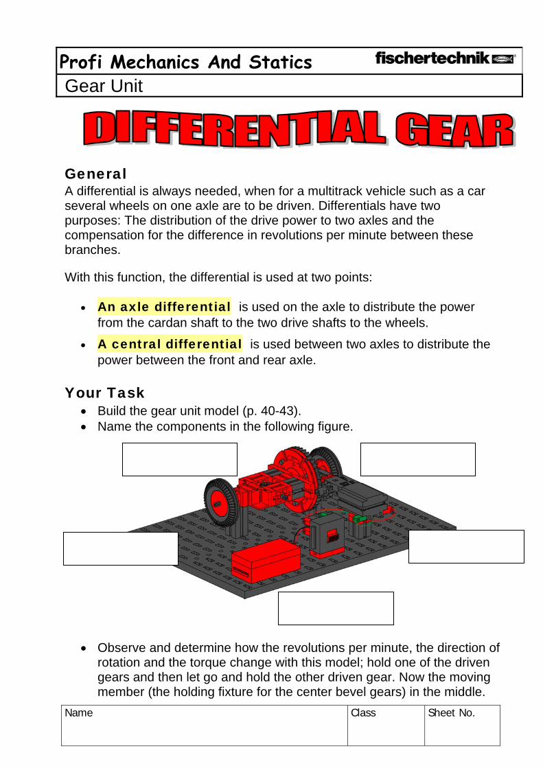
General A differential is always needed, when for a multitrack vehicle such as a car several wheels on one axle are to be driven. Differentials have two purposes: The distribution of the drive power to two axles and the compensation for the difference in revolutions per minute between these branches.
With this function, the differential is used at two points:
• An axle differential is used on the axle to distribute the power from the cardan shaft to the two drive shafts to the wheels.
• A central differential is used between two axles to distribute the power between the front and rear axle.
Your Task
• Build the gear unit model (p. 40-43). • Name the components in the following figure.
• Observe and determine how the revolutions per minute, the direction of rotation and the torque change with this model; hold one of the driven gears and then let go and hold the other driven gear. Now the moving member (the holding fixture for the center bevel gears) in the middle.

Profi Mechanics And Statics Gear Unit
Name
Class Sheet No.
• Record your observations in the table. Hold Driven gear 1 Driven gear 2
Revolutions per minute
Direction of rotation Solution The differential appears to be a real magic gear unit.
It is used the most in cars: When a car travels around a curve, the outside wheel travels a greater distance than the inner wheel in the curve. Without a differential, the driven wheels would rub on the road and would wear significantly faster.
The differential on an axle has another interesting characteristic: It divides the torques evenly (50:50) and distributes these to the wheels.

Profi Mechanics und Statics Mandril Screw Spindle and Joint
Name
Class Sheet No.
General You certainly have a lot of friends, who can help you when you need to transport heavy loads. However, there are situations where you are by yourself. One of these situations could be a flat tire. Just imagine that you would have to lift the whole car to change a tire. Of course, you can’t do that. That’s why a car has a car jack. Using this device, anybody can lift heavy loads alone. The trick is a mandril screw spindle. The mandril screw spindle uses the special characteristics of the worm gear. Your Task
• To examine the way a car jack functions, first build the model of the car jack. See the construction instructions on p. 44-45.
• Name the individual components in the figure and use these
terms: Spindle, pivotal point, lever, worm nut and load support.

Profi Mechanics und Statics Mandril Screw Spindle and Joint
Name
Class Sheet No.
• Turn the crank one time and observe and measure how far the worm nut moves and how high the lever of the car jack rises. For the measurements use a steel ruler or your geometry set square.
Observations ..................................................................................................................................................................................................................................................................................................................................................................................................................................................................................................................................................................................... • Press on the lever. Does the screw spindle rotate backwards?
Explain your observations.
.................................................................................................................
.................................................................................................................
.................................................................................................................
.................................................................................................................
.................................................................................................................
• Can you name two reasons why a screw spindle mechanism is used for this purpose?
.................................................................................................................
.................................................................................................................
.................................................................................................................
.................................................................................................................
.................................................................................................................
................................................................................................................. Addition To put the lever in a vertical position, you had to turn the crank several times. You certainly saw that the lever cannot be pushed downwards. A screw spindle mechanism has many advantages:
• It reduces the revolutions per minute of the drive many times. • It is self-locking. • It increases the force of the drive.
Profi Mechanics und Statics Mandril Screw Spindle and Joint
Name
Class Sheet No.
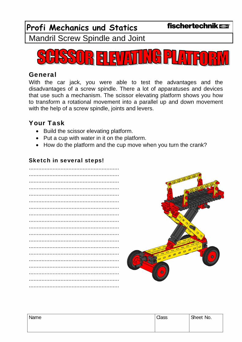
General With the car jack, you were able to test the advantages and the disadvantages of a screw spindle. There a lot of apparatuses and devices that use such a mechanism. The scissor elevating platform shows you how to transform a rotational movement into a parallel up and down movement with the help of a screw spindle, joints and levers. Your Task
• Build the scissor elevating platform. • Put a cup with water in it on the platform. • How do the platform and the cup move when you turn the crank?
Sketch in several steps! ............................................................................................................................................................................................................................................................................................................................................................................................................................................................................................................................................................................................................................................................................................................ ...................................................................................................................................................................................................................................................................................................................................................... .........................................................

Profi Mechanics und Statics Mandril Screw Spindle and Joint
Name
Class Sheet No.
Solution With the joint, the output of the screw spindle, that is the back-and-forth movement of the worm nut is transferred to another level, that is to the platform. Since the pivotal point for both joints is in the common center, the lifting, that is the up and down movement of the platform, runs parallel to the screw spindle. Both joints move the same distance just like scissors. That’s why it is called a scissor elevating platform.

Profi Mechanics and Statics Coupled Gear
Name
Class Sheet No.
General The windshield wiper model gives you the opportunity to examine the transformation of rotational movements into back-and-forth or oscillating movements. Here, the crank disk or cam disk is used. This type of gear unit is called a crank-rocker gear unit. It transforms a rotational movement into a straight-line movement. As a double four-bar chain, it consists of the components that you are to assign in the following task. Your Task
• To examine the way a windshield wipe functions, first build the model of the windshield wiper. See the construction instructions on p. 56-59.
• Name the individual components in the figure and use these terms: crank, gear rocker, frame and connecting rod.

Profi Mechanics and Statics Coupled Gear
Name
Class Sheet No.
General The four-bar chain consists, as the name implies, of four joints, that is points, at which something can rotate. A simplified diagram of the four-bar chain shows you how it works.
Your Task • Build the crank gear. • Observe and determine how the
individual components interact. ......................................................................................................................................................................................................................................................................................................................................................................................................
• Note what components move and those that don't. Describe the type of
movement in the following table.
Component Moves
(Yes, No) Type of movement
Crank Connecting rod
Gear rocker Frame

Profi Mechanics and Statics Coupled Gear
Name
Class Sheet No.
Solution The frame is rigid and absorbs the movements, which occur. The crank must be able to make entire revolutions and the connecting rod transfers the movement of the crank to the gear rocker. The gear rocker makes its movement in an arc only because it is fastened to the frame. To allow the gear unit to really function, the lengths of the four components of the crank rocker must be precisely adjusted to each other. This means that the lengths of the components must be in a certain relation to each other.

Profi Mechanics and Statics Coupled Gear
Name
Class Sheet No.
General The effect of the crank rocker is also used in other areas. For a long time, the frame cross cut saw was a big help for the metal construction builders. The simple structure of it mechanics is meant to help you to better understand a crank gear unit. With this type of gear unit, a rotational movement is transformed into a back-and-forth movement. The end points, where the saw cannot go any farther are called the dead center points T1 and T2. Your Task
• Build a copy of the gear unit model. • Measure the stroke of your saw and write down the result.
The stroke of the frame cross cut saw is .............. mm long.
Gestell
Schubstange KoppelExzenter /Nockenscheibe
Kurbel T1 Hub T2
Crank
Eccentric, cam disk Connecting rod Push rod
Frame Frame T1 Stroke T2

Profi Mechanics and Statics Lever
Name
Class Sheet No.
General To determine the price of an item, the quantity of the item was compared to weights and this started 4000 years ago. Using the beam and scales the weight force of two masses or a weight are compared. Thus, the beam and scales measures the balance of two weight forces. For your model, this is a beam attached at mean pivotal center and the beam has a bowl at each end. Both pointers in the middle of the balance beam must be in line when the forces are balanced. Your Task
• Build the beam and scales using the construction instructions on p. 66-69.
• Put a fischertechnic building block in both weighing bowls. Are your scales working properly?
Yes No
• Now look for two objects, which have the same weight in your opinion, and put them in the weighing bowls.
Object left weighing bowl Object right weighing bowl
• Were you right? Try it out until the pointers on your scales agree.

Profi Mechanics and Statics Lever
Name
Class Sheet No.
Solution These scales work according to the principle of levers of equal length. A lever is a straight beam, which is attached in a manner allowing it to rotate and on which two forces act. The distances between the application points of the forces and the pivotal center are called the lever arms. Both sides beside the pivotal center are of equal length and equal weight. You know the principle of these scales from the seesaw. For the levers to be balanced, the length of both levers must be the same and the weight on the levers must be the same as well. In addition, the distance of the weights to the pivotal center of the scales must also be the same.

Profi Mechanics and Statics Lever
Name
Class Sheet No.
General You have to have a bit of patience to find two weights that have exactly the same weight. That’s why a further development of the beam and scales is scales with a sliding weight. These scales also work according to the principle of levers of the same length, but here torques are used as a sort of trick. Both sides beside the pivotal center are the power arms. The further to the outside that a weight hangs on a power arm, the higher its force. With the help of the slider, the torque on a power arm can be changed. The arm with the weighing bowl is called the lift arm in this case. Your Task
• Build the scales with a lift arm and power arm and sliding weight (p. 70-74).
• Move the sliding weight so that the scales are balanced when no weight is in the bowl. The pointer in the middle of the scales helps you to do this.
• Put a weight in the weighing bowl. Balance the scales with the sliding weight.
• Write down your observations.
...................................................................
...................................................................
...................................................................
...................................................................
...................................................................
...................................................................
...................................................................
...................................................................
...................................................................
...................................................................
...................................................................
...................................................................

Profi Mechanics and Statics Lever
Name
Class Sheet No.
Solution To put a lever in balance, the sum of the counter-clockwise torques and the sum of the clockwise torques must be equal. This sounds unbelievably complicated at first, but it is really not that difficult. The law says that both arms to the left and right of the pivotal center have to have the same weight, but not that they have to be the same length. The farther away a weight is from the pivotal point, the greater the force of the lever and so its weight as well.
Profi Mechanics and Statics Lever
Name
Class Sheet No.
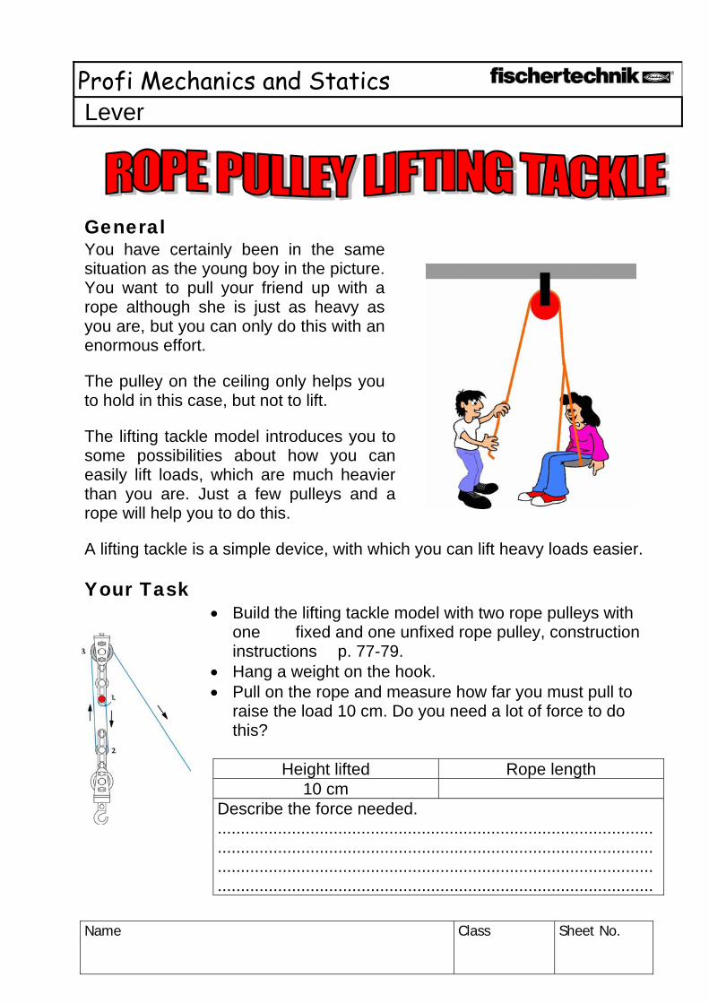
General You have certainly been in the same situation as the young boy in the picture. You want to pull your friend up with a rope although she is just as heavy as you are, but you can only do this with an enormous effort.
The pulley on the ceiling only helps you to hold in this case, but not to lift.
The lifting tackle model introduces you to some possibilities about how you can easily lift loads, which are much heavier than you are. Just a few pulleys and a rope will help you to do this.
A lifting tackle is a simple device, with which you can lift heavy loads easier.
Your Task • Build the lifting tackle model with two rope pulleys with
one fixed and one unfixed rope pulley, construction instructions p. 77-79.
• Hang a weight on the hook. • Pull on the rope and measure how far you must pull to
raise the load 10 cm. Do you need a lot of force to do this?
Height lifted Rope length
10 cm Describe the force needed. .............................................................................................. .............................................................................................. .............................................................................................. ..............................................................................................

Profi Mechanics and Statics Lever
Name
Class Sheet No.
Solution With this model, you can say that the load is distributed to three ropes. This is not exactly right because your rope hasn't really been cut, but the force needed is reduced to one-third.

Profi Mechanics and Statics Lever
Name
Class Sheet No.
Your Task • Expand your first model to a lifting tackle
with three rope pulleys (construction instructions p. 80-81).
• Pull on the rope and measure how far you must pull to raise your load 10 cm. Do you need a lot of force to do this?
• Record and compare your observations in the table.
Length pulled in
cm Force needed according
to your feeling Number of rope
pieces Three rope
pulleys
Solution This type of lifting tackle is called a four-strand lifting tackle because the force and the weight are distributed to four pieces of rope.
Profi Mechanics and Statics Lever
Name
Class Sheet No.
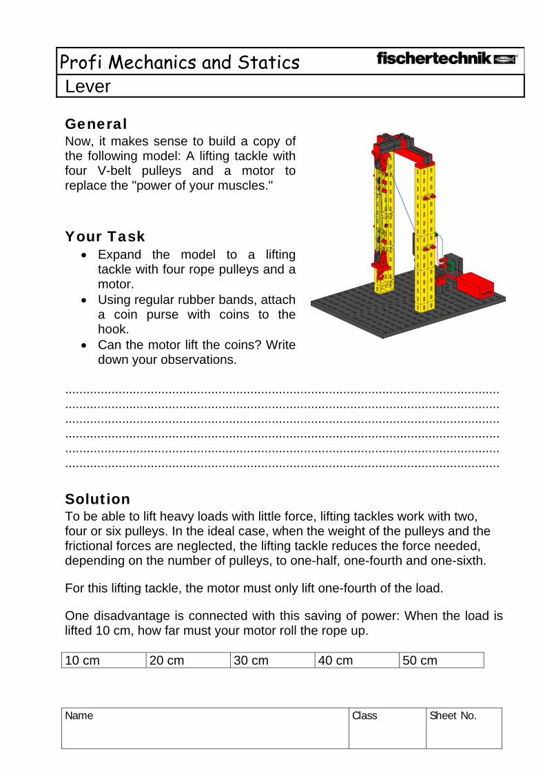
General Now, it makes sense to build a copy of the following model: A lifting tackle with four V-belt pulleys and a motor to replace the "power of your muscles." Your Task
• Expand the model to a lifting tackle with four rope pulleys and a motor.
• Using regular rubber bands, attach a coin purse with coins to the hook.
• Can the motor lift the coins? Write down your observations.
.................................................................................................................................................................................................................................................................................................................................................................................................................................................................................................................................................................................................................................. .......................................................................................................................... Solution To be able to lift heavy loads with little force, lifting tackles work with two, four or six pulleys. In the ideal case, when the weight of the pulleys and the frictional forces are neglected, the lifting tackle reduces the force needed, depending on the number of pulleys, to one-half, one-fourth and one-sixth.
For this lifting tackle, the motor must only lift one-fourth of the load.
One disadvantage is connected with this saving of power: When the load is lifted 10 cm, how far must your motor roll the rope up. 10 cm 20 cm 30 cm 40 cm 50 cm

Profi Mechanics and Statics Lever
Name
Class Sheet No.
Physics understands the way your lifting tackle works and has invented a law for this and this law is called the "Golden Rule," which states that "Work cannot be saved, whatever is saved on force, must be added in time and distance!"

Profi Mechanics and Statics Statics
Name
Class Sheet No.
General Statics studies conditions, under which the forces acting on a body are in balance. Thus, for technology, this is the basis for all calculations and designs of constructions such as bridges and houses. Various forces act on components of statics. The weight of a construction is called dead weight. The weight of people, furniture, plates or even cars, which act on a statical construction, is called traffic load. The table is one of the most-used statical objects in your surroundings. The table carries both traffic loads and its own weight, that is its dead weight. Traffic loads are mostly plates and cups and the food and drinks that are on the table. But your arms that are on the table are also a traffic load just as any accidental bumping of the table. So that a table can handle all of these loads, it needs a lot of statical specialties.

Profi Mechanics and Statics Statics
Name
Class Sheet No.
Your Task • Build the table (construction instructions p. 85-87). • Insure that the struts are correctly connected when you build the table. • First, put a load on the table from above. Next, press on the table top
from the side and then against one of the table legs. What happens in each case?
..........................................................................................................................
..........................................................................................................................
..........................................................................................................................
.......................................................................................................................... Solution
The statical characteristics of your model table consist of the angled table legs and they are stable in two directions due to the angle. The frame construction of the table is also supported with struts and braces. This means that the yellow struts between the table legs stabilize the frame with respect to weight and side pull. But, the crowning moment of statics are the connection points, which form triangles. Triangles are also stable, meaning not movable, when the rods at the connection points have movable joints. Such triangles are called statical triangles. So your model table is statically stable in three aspects. In statics, all connection points are called nodes.
Your Task
• Remove the braces and place a load on the table. What effect does this removal of the braces have on the statics of the table?
..........................................................................................................................
..........................................................................................................................
..........................................................................................................................
..........................................................................................................................
..........................................................................................................................
..........................................................................................................................
..........................................................................................................................
..........................................................................................................................

Profi Mechanics and Statics Statics
Name
Class Sheet No.
• Put the braces back in. Now remove the struts. Place a load on the
table again. How stable is your table now? .............................................................................................................................................................................................................................................................................................................................................................................. .......................................................................................................................... .......................................................................................................................... .......................................................................................................................... .......................................................................................................................... ..........................................................................................................................
• Now remove the braces again. Place a load on the table and describe your observations.
..........................................................................................................................
..........................................................................................................................
..........................................................................................................................
..........................................................................................................................
..........................................................................................................................
..........................................................................................................................
..........................................................................................................................
..........................................................................................................................

Profi Mechanics and Statics Statics
Name
Class Sheet No.
General
The double ladder also has a very simple statical construction. This ladder also uses angled legs, which are supported by struts. The struts between the legs also serve as ladder rungs. Thus, the double ladder consists of two individual ladders, which are connected at a pivotal center at the top. In addition, there is bracing of both ladders in the lower part.
Your Task
• Build the double ladder (p. 88-90), but first without any bracing. • Set the double ladder up and place a load on it by pressing on the
rungs and the upper pivotal center. Does the ladder remain stable?
..........................................................................................................................
..........................................................................................................................
..........................................................................................................................
• Now, install the braces on your ladder. Now test the ladder again. Does the ladder remain standing now?
.................................................................................................................................................................................................................................................... ..........................................................................................................................

Profi Mechanics and Statics Statics
Name
Class Sheet No.
Solution A double ladder consists of two halves that are the same, which are connected with a pivotal center at the top. Depending on the clearance angle for both halves, the ladder can remain standing without any bracing. But at a certain point, the "feet" of the ladder begin to slide and the ladder halves are pushed away from each other. The bracing stabilizes the ladder.

Profi Mechanics and Statics Statics
Name
Class Sheet No.
General Bridges connect what nature has separated or pass safely over streets and railways. For millenniums, bridges have created what appears to be weightless paths. An optimal bridge has four characteristics: It is safe, long, cheap and looks good. With your first bridge model, you will get to know a classic of bridge building. Your Task
• Build a copy of the bridge model (construction instructions p. 91).
• Place a load on the bridge in the middle. Write down your observations.
..........................................................................................................................
..........................................................................................................................
..........................................................................................................................
• Where do you suppose that this bridge can be used? ..............................................................................................................................................................................................................................................................................................................................................................................
Belastung Load

Profi Mechanics and Statics Statics
Name
Class Sheet No.
Solution This single-span girder bridge is excellently suited for low loads and small span lengths. It fulfills all requirements. However, if the distance between the supports is greater, the bridge loses its stability.

Profi Mechanics and Statics Statics
Name
Class Sheet No.
General The bridge with underbeam is similar to a suspension bridge in its design. However, this bridge has almost nothing in common with the design of a suspension bridge. You will find out why this is so during experiments with the model. Your Task
• Build the bridge with underbeam (construction instructions p. 94-95).
• Place a load on the bridge in the middle. Use a weight that weighs about 1 kg.
• Write down your observations. ............................................................................................................................................................................................................................................................................................................................................................................. .............................................................................................................................................................................................................................................................................................................................................................................. .......................................................................................................................... .......................................................................................................................... .......................................................................................................................... .......................................................................................................................... .......................................................................................................................... ..........................................................................................................................

Profi Mechanics and Statics Statics
Name
Class Sheet No.
Solution The bridge with underbeam functions based on its framework construction. This type of construction is suited for large loads, but not for big span lengths. The biggest span lengths are achieved with suspension bridges. The similarity of the bridge with underbeam and a suspension bridge is thus only an optical similarity. Seen statically, the bridge types are completely different.

Profi Mechanics and Statics Statics
Name
Class Sheet No.
General An upper boom (upper beam) bridge can have longer span lengths and withstand greater loads. This type of bridge uses the framework design, which you already know. Struts, braces and statical triangles stabilize this bridge. Your Task
• Expand your first bridge model to a bridge with overbeam. • Place a load on the bridge in the middle. • Write down your observations. How has the stability of the bridge
changed? • Name all of the statical elements you know in the drawing.
The upper boom, the struts, the braces and the supports. Enter the terms in the fields and connect them with the components.

Profi Mechanics and Statics Statics
Name
Class Sheet No.
Solution This bridge form can withstand weight better than the girder bridge. The compressive force is now transmitted not only to one girder, but is also distributed to the additional components. The upper boom consists of crossed diagonals, which are attached to the upper nodes of the side elements. The diagonals on the upper boom prevent the twisting of the bridge. If the struts project upwards, then this bridge design is called a truss frame.

Profi Mechanics and Statics Statics
Name
Class Sheet No.
General If you have had enough of bridges and would prefer to go to higher places, than the high hunting stand is just right. Of course, the high hunting stand does not have to bridge any valleys, but it does reach some heights. The statical basis for this is the framework, which is the area joining of triangles. The individual elements of statics are also constructed here. Your Task
• Build the high hunting stand using the construction instructions on p. 101-107.
• Do you recognize the construction elements? • Write these down in items 1 to 6 and identify them in the figure with the
correct number. 1. .......................................
2. .......................................
3. .......................................
4. .......................................
5. .......................................
6. .......................................

Profi Mechanics and Statics Statics
Name
Class Sheet No.
Solution The spatial composition of individual frameworks is called a skeleton. Skeletons of frameworks are found in house construction, high voltage towers, your bridge designs and also in the high hunting stand model. Such skeletons have the advantage that they must not be filled with a plate, a disk or with stone and thus offer little surface resistance to wind. This type of construction also uses considerably less building materials, but still provides the highest degree of stability.
Profi Mechanics and Statics Statics
Name
Class Sheet No.
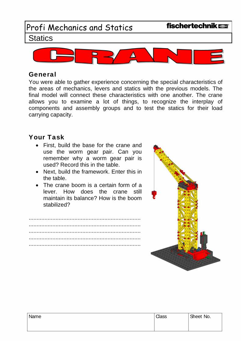
General You were able to gather experience concerning the special characteristics of the areas of mechanics, levers and statics with the previous models. The final model will connect these characteristics with one another. The crane allows you to examine a lot of things, to recognize the interplay of components and assembly groups and to test the statics for their load carrying capacity. Your Task
• First, build the base for the crane and use the worm gear pair. Can you remember why a worm gear pair is used? Record this in the table.
• Next, build the framework. Enter this in the table.
• The crane boom is a certain form of a lever. How does the crane still maintain its balance? How is the boom stabilized?
....................................................................... ............................................................................................................................................................................................................................................................................................

Profi Mechanics and Statics Statics
Name
Class Sheet No.
Assembly group Advantages,
Special characteristics
Possible uses Components
Mechanics Worm Gear Pair Statics Lever
Possible Additions There are several types of gear units available for lifting weights.
• Install the possible gear units in your crane model. • Compare the way they function. • Enter the results in the table.
The crowning element for your model is the use of a lifting tackle.
• Develop a lifting tackle for your crane model. • What do you have to consider, so that your crane can also lift and
lower heavy loads?