ad-•51 ii seismic design of building structures · ad-•51 17-8 ii seismic design of building...
TRANSCRIPT

AD-•51 17-8
Ii
Seismic Design of
Building Structures
New Mexico University
prepared for
Army Construction Engineering Laboratory
JULY 1972
Distributed By:
Natinal Technical Information ServiceU. S. DEPARTMENT OFý COMMERCE5285 Port Royal Road, Springfield Va. 22151
AI

ISCLAIMEI NOTICE
THIS DOCUMENT IS BEST
QUALITY AVAILABLE. THE COPY
FURNISHED TO DTIC CONTAINED
A SIGNIFICANT NUMBER OF
PAGES WHICH DO NOT
REPRODUCE LEGIBLY.
TECHNICAL REPORT S-10
July 1972
SEISMIC DESIGNOF BUILDING STRUCTURES
by
J.T.P. YaoC. Omid'varanA. Gorpinar
C. L. Hulsbos
RCONSTRUCTION ENGINEERING RESEARCH LABORA TORY
Champaign, lllinois 61820
Repr ¢ud-d by
NATIONAL TECHNICAL NOV 14 1972INFORMATION SERVICEU S L, 0v' e*c C., -- er
S yf d ý A -~15
B .-
Approved for public release; distribution unlimited.

The contents of this report are not to be used for advertising, publication, oa promotionalpurposes. Citation of trade names does not constitute an official endorsement or pMovulof the use of such commercial products. The findings of this report are not to beconstrued as an official Department of the Army position, unless so designated by otherauthorized documents.
AME]SSIOIfN" w
rTIS white Sot'ws IY
DETO #1V REPOR WHHN 0TSN OGRNEE
ONT'. RDRNf ITT0EOII'O,1 li l A i ........... .......................
B Y .......... I.................... ..... .. ...
DISTR1111T7O01/AVAfLADILIT1Y CODES
Dis. AWAL. u~,'rd/ ,CA
DEMTOY THUSREPORT WHEN IT I$ NO LONGER NEEDED
DO NOT RE•TVXN IT TO ?7WE ORIGINAT7OR
_UNCLASFEDsecurit Classification, I i
DOCUMENT CONTROL DATA - R &O .(SCfivityl Classifcation Of title, bogeelat "steet A" h4eIndein am •otae must be entered Whom, th oveeonlrepot to €lesonlf~i
I. OMIGINAT1IMS ACTIVITY (C06140180o ther &aIIa. REPORT SECURItTW coASSBItC&Ttaf
Department of the Army UnclassifiedCONSTRUCTION ENGINEERING RESEARCH LABORATORY 8b. GROUP
P.O. Box 4005 Champaign, Illinois 61820). mRPORT TITIE
SEISMIC DESIGN OF BUILDING STRUCTURES
4. OESCRIPTIVE NOTES (Tpe of rIport and • a•hia.e dotes)
Final Report. AuTNORIS) (Pil almE. iniddo muist. lame VMMS)
J.T.P. Yao, C. Omid'varan, A. Gilrpinar, C.L. Hulsbos6 REPORT DATE 7T. TOTAL NO. OF PAi9S Tb. NO. Or Rare
July 1972 150 2898& CONTRACT OR GRANT NO. 0*. ORIGINATORNS REPORT NUMUR(SIC
DACA 23-70-C-00626. PROJECT NO. TECHNICAL REPORT S- 10
:" 4DM78012AOKI'-.Task -03 to re:=po") ... €...-.-...
WorkUobt AD# from block 1 address
S10, OISfTAINJTION STATEME*INT
Approved for public release; distribution unlimited.
it. SUPPLEMENTARY NOTES 12. SPONSORING MILITARY ACTIVITYCopies of this report available from:
V4ational Technical Information Servic Department of the ArmySpringfield, Virginia 22151 i
ISl. AEISTRACT
The purpose of this project was to formulate possible improvementsin the design codes concerning building structures which are subjected toearthquake loads. In addition, suggestions were made concerning ways toincorporate the concepts and methods of discrete mechanics, statisticalanalysis, as well as earthquake behavior of concrete and metal structuresinto the seismic design code.
Available literature on existing design codes is summarized herein.Design philosophies and methodologies in earthquake engineering were alsostudied. A "design-tree" technique was then adapted to present the recom-mended improvements in the context of existing specifications. Moreover,approaches to certain expected problems for the implementation of theseimprovements were outlined along with a set of recommendations. Furthermore,literature reviews and some original contributions in discrete mechanics,statistical methods, and dynamic behavior of structures are given in threeappendices as backgroung information.
14. KIEY WORDS
Seismic Dbsign Earthquake resistant structures: concrete constructionsteel construction
OSS1OLSTE P041 AMS WeeS.D D 1P6vSl4 73 "REPLACE* " *-- "I's' 1 "A ww"' I s a Fir&C-i MDIii IM,"IIVOSIo~
S. . . . . .. • . .. . l m .. . .. . ... . . . ..I L. .

TECHNIICAL REPORT S-10
SEISMIC IESIQG OF BUILDING STRUCTURES
by
J. T. P. YaoC. Omid'varan
A. GirpinarC. L. Hulsbos
research performed at
University of New MexicoCONTRACT No.: DACA 23-70-C-0062
July 1972
Department of the ArmyCONSTRUCTION ENGINEERING RESEARCH LABORATORY
P.O. Box 4005Champaign, Illinois 61820
Approved for public re distribution unlimited.

ABSTRACT
The purpose of this project was to formulate possibleimprovements in the design code concerning building struc-tures which are subjected to earthquake loads. In addition,
*; suggestions were made concerning ways to incorporate theconcepts and methods of discrete mechanics, statistical anal-ysis, as well as earthquake behavior of concrete and metalstructures into the seismic design code.
Available literature on existing design codes is sum-marized herein. Design philosophies and methodologies inearthquake engineering were also studied. A "design-tree"technique was then adapted to present the recommended im-provements in the context of existing specifications. More-over, approaches to certain expected problems for the imple-mentation of these improvements were outlined along with aset of recommendations. Furthermore, literature reviews andsome original contributions in discrete mechanics, statisti-cal methods, and dynamic behavior of structures are givenin three appendices as background information. A simpleillustration of the direct approach to seismic design is contained inthe fourth appendix.
iii

This investigatian was. performed in the Department of the CivilEngineering at the University of New Mexico for the U.S. Army Ccnstruc-tian Engineering Research Laboratory (CERL) under Contract No.: DACA23-70-C-0062. This research was performed under Project 4ED78012AOK1,"Engineering Criteria for Design and Construction," Task 03, "SystemCriteria for Environmental Isolation and Ccntrol," Work Unit 007,"Earthquake Effects." Tedcical Monitor was Dr. James Prendergast.
This research was accwplished May - Noventer 1970 by Dr. J. T. P.Yao, who prepared Appendices B and D and was responsible for coordi-nating the research effort; Dr. C. Omid'varan, who prepared Appendix A;Mr. A. Girpinar, who prepared Part II; and Dr. C. L. Hulsbos who pre-pared Appendix C.
Dr. Walter E. Fisher, Chief of Buildings Branch, CERL, initiatedthe project. The advice and guidance of both Drs. Fisher and Prender-gast throughout the duraticn of this project were appreciated. Mr. J. J.Healy, Chief of Ccnstructian Systems Laboratory, CRL, also gave hissupport and encouragement tr these investigators. Col. E. S. Townsleyand Dr. L. R. Shaffer were Director and Deputy Director, respectively,of CERL.
iv
CONTENTS
PAGE
ABSTRACT iii
FOREWORD iv
LIST OF TABLES, FIGURES vii
PART I: INTRODUCTION 1
General 1
Objective and Scope 3
PART II: EXISTING SEISMIC DESIGN CODES 5
General 5
Equivalent Lateral Forces 6
Overturning Moment 26
Torsion 28
Allowable Stresses 30
Other Considerations 32
PART III: POSSIBLE IMPROVEMENTS IN THE DESIGN CODE 36
General 36
Design Philosophies and Methodologies 36
Direct Approach 41
Implementation Problems and Approachesto These Problems 50
PART IV: CONCLUSIONS AND RECOMMENDATIONS 55
Conclusions 55
Recommendations 55
v
CONTENTS (concluded)
PAGE
APPENDIX A REVIEW OF DISCRETE MECHANICS AND SOMEORIGINAL SOLUTIONS 58
APPENDIX B STATISTICAL METHODS 79
APPENDIX C SEISMIC BEHAVIOR OF CONCRETE AND METALSTRUCTURES 94
APPENDIX D AN IILfSTRATIWN CF THE DIRELT APPR)ACH 115
IMFERMES 120
DISTRIBUTINiDD •O•4 1473
vi

LIST OF TABLES, FIGURES
Table Pg
1 GEOFIAN Scale for Earthquakes (56) 20
2 Reduction Coefficients in Japanese Code (63) 24
3 "Answers" in Design Trees as Shown inFigures 3 and 4 44
4 Effect of Settlement to Structural Damage(234) 95
5 Earthquake Damages in Skopje (239) 98
Figure
1 Relations Between Pure Research, Applied
Research, and Practical Applications (2) 38
2 Design Trees 40
3 "Design Tree" for Existing Seismic DesignCodes 42
4 "Design Tree" for a Direct Approach 43
5 Continuous Beam 59
6 The Free Body Diagram of Joint LoadedEquivalent System 60
7 Cross-Braced Truss 62
8 Free Body Diagram of Joint "r" 63
9 Lumped Mass Beam 65
10 The Free Body Diagram of Mass "r" 65
11 The Free Body Diagram of Panel "r" 65
12 Discrete Model of a Multi-Story Frame 68
13 Free Body of Mass "r" 68
14 Shearing Forces on Mass "r" 69
vii
LIST OF TABLES, FIGURES (concluded)
Figure Page
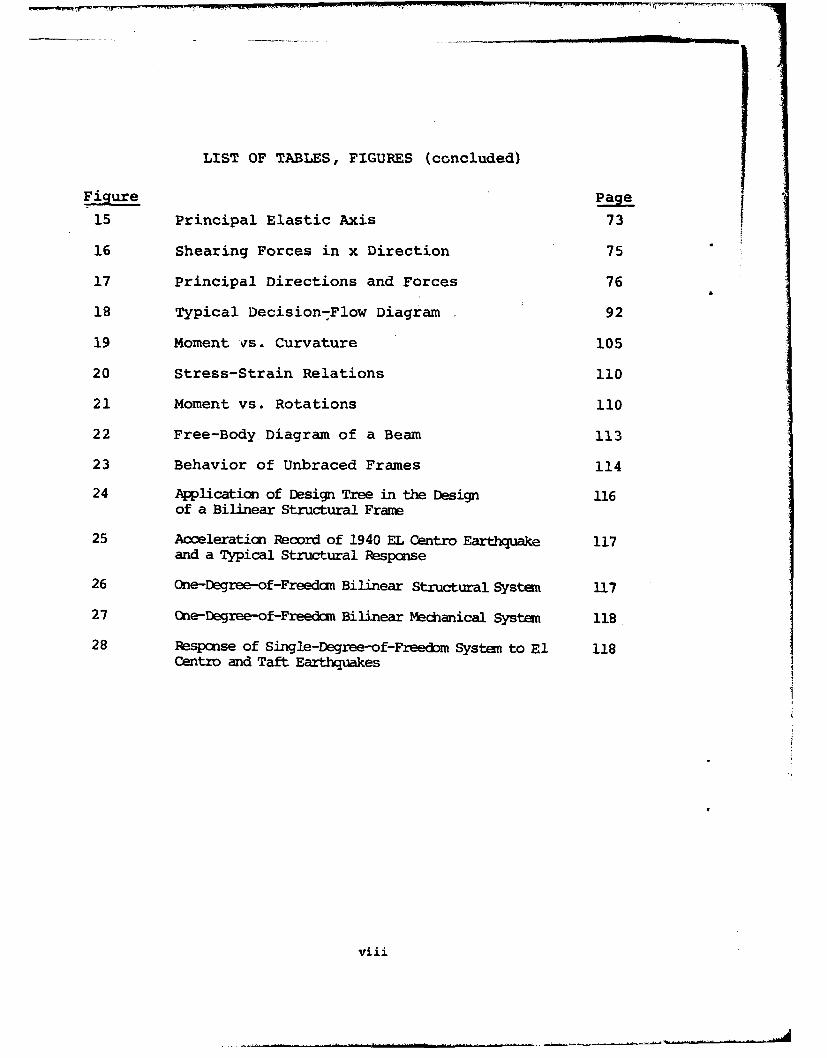
15 Principal Elastic Axis 73
16 Shearing Forces in x Direction 75
17 Principal Directions and Forces 76
18 Typical Decision-Flow Diagram 92
19 Moment qs. Curvature 105
20 Stress-Strain Relations 110
21 Moment vs. Rotations 110
22 Free-Body Diagram of a Beam 113
23 Behavior of Unbraced Frames 114
24 Application of Design Tree in the Design 116of a Bilinear Structural Frame
25 Acceleraticn Record of 1940 EL Centro Earthquake 117and a Typical Structural Respcnse
26 One-Degree-of-Freedam Bilinear Structural System 117
27 One-Degree-of-Freedom Bilinear Mechanical Systen 118
28 Respcnse of Single-Degree-of-Freecbm System to El 118Centro and Taft Earthquakes
viii
SEISMIC DESIGN OF BUILDING STRUCTURES
PART I: INTRODUCTION
General
It is a well known fact that, throughout man's history,human life and property have been lost during strong-motionearthquakes. As examples, (a) property damage from the 1964Alaska Earthquake was on the order of $300 million, (b) al-most 11,000 persons lost their lives duriny the 1968 IranEarthquake (1, 2)*, and (c) over 40,000 persons died duringthe recent 1970 Peru Earthquake. Detailed descriptions ofthe damage from the Alaska Earthquake as well as other re-cent earthquakes can be found elsewhere (3-7). While it isnot possible at present to prevent the occurrence-of strang-nxotionearthquakes, cantinous efforts have been made to improvethe design of structures in order to minimize the earthquakedamage of civilian as well as military structures.
Existing specifications concerni .x earthquake loadssuch as the Uniform Building Code (8), Recommended LateralForce Requirements (9), and Seismic Design for Buildings(10), provide a set of equivalent static lateral loads. Al-though these codes are based on the dynamic analysis ofeari.iquakes (11), Blume (12) has shown that structural de-formations induced by loads based on code requirements maybe considerably less than those computed for the same struc-ture subjected to the excitation of a recorded strong-motionearthquake. As Blume pointed out, the safety of the struc-ture against collapse is greater than that indicated by thelinear analysis because a considerable amount of damping isintroduced by the failure of "architectural clothing" aswell as the elasto-plastic behavior of the frame.
Veletsos and Newmark (13) studied an elasto-plasticsingle-degree-of-freedom system subjected to earthquake mo-tions corresponding to the 1940 El Centro and the 1933Vernon earthquakes. Penzien (14) investigated the responseof an elasto-plastic system to the ground motion of the1940 El Centro earthquake, which confirmed the thought thatthe maximum displacements are less in elasto-plastic sys-tems than those in corresponding elastic systems. Sincethen, nonlinear and yielding seismic structures have beenstudied by Jennings (15), Goel and Berg (16), and Penzien
*Parenth]etic numerals indicate references.
I

and Liu (17). The results of these studies seem to confirma generally accepted design philosophy which aims at an elas-tic response in the case of small (and frequent) earthquakesand to permit inelastic response in the case of strong-motion (and infrequent) earthquakes. However, it is wellknown that plastic deformations can cause cumulative damage,which could lead to low-cycle fatigue failure of structures(18) .
Due to the random characteristics of earthquakes, sev-eral probabilistic models have been proposed to representearthquake ground motions. Housner (19) represented theearthquake as a series of impulses that were random in time.Thomson (20) showed that it is reasonable to use white noiseto describe earthquake motions. Bycroft (21) then proposed"a specific white noise with a constant spectral density and"a fixed duration for the representation of a standard strong-motion earthquake. Bogdanoff, Goldberg, and Bernard (22)suggested a nonstationary random process consisting of a sumof damped sinusoids to represent earthquake accelerations.In a subsequent paper, this model was modified by Goldberg,Logdanoff, and Sharpe (23). Lin (24) proposed a nonstation-ary random process resulting from a filtered shot noise,which has become a popular model in the study of seismicstructures to date.
Stationary random processes for earthquake simulationhave been developed by Housner and Jennings (25) using adigital computer, and by Ward (26) using an analog computer.Earthquake gcound motion is generally regarded as a non-sta-tionary random process. Digital computer simulation of non-stationary earthquake motion has been performed by Ar n andAng (27), Jennings, Housner, and Tsai (28), Shinozuka andSato (29), Rascon and Cornell (30), Levy (31), Hou (32), andIyengar and Iyengar (33). The simulation proposed by Rasconand Cornell (30) attempts to account for most of the pertin-ent physical characteristics of earthquakes. The results ofJennings, Housner, and Tsai (28) as well as Iyengar andIyengar (33) contain parameters which account for differentearthquake types. Recently, Wirsching and Yao (34) com-pleted a Monte Carlo study of bilinear seismic structuresusing analog computation.
The distribution of earthquake occurrences in time andspace has been considered by Rosenblueth (35), Benjamin (36),Cornell (37), and Shinozuka (38). Benjamin (36) used Bayestheorem and computed the posterior probabilities of theearthquake occurrences. Cornell (37) showed that the earth-quake intensity is a function of distance from a fault. Re-cently Wirsching and Yao discussed the probability distribu-
2

tion of structural response to simulated earthquakes (39).
The traditional techniques for dynamic analysis of highlyredundant framed structures can be referred to as "piece bypiece" methods of analysis, which call for tedious and inde-pendent dynamic analysis of each structure in the sense thatany variation in the framework properties and applicableparameters requires the development of a new solution. Re-cent developments in the field of mechanics makes it feasibleto develop explicit functional solutions and formulas for dy-namic characteristics of frames, applicable to prescribed pat-terns and formations with arbitrary number of bays and levels.The classical literature concerning functional field solutionto structures is due to Bleich and Melan (40). The develop-ment and application of the technique to dynamic analysis offramed structures is due to Wah (41), Leimback and McDonald(42), Ellington and McCallion (43), and Dean and his col-leagues (44). The technique employs the calculus of finitedifferences and discrete mechanic concepts to derive the dif-ference-differential equations describing the dynamic be-havior of framed structures. It results in functional solu-tions which are exact within the scope of linear beam theoryand yet describes the dynamic behavior of various types offramed structures.
Although the existing seismic design codes are basedsomewhat on a dynamic analysis, the use of a set of "equiv-alent" static loads does not result in a solution which fullydescribes the dynamic behavior of structures under earthquakeloading conditions. The practice of employing an "equivalentstatic loading" is known as a compromise solution with trace-able deficiencies. It was recommended in lieu of the com-plexity of a dynamic analysis and limitations of the state ofthe art. Moreover, the statistical characteristics of earth-quakes were totally disregarded. Results of many investiga-tions concerning the dynamic behavior of framed structuresare now available. These and field solution techniques arepromising as a supplemental to statistical methods in serv-ing to provide a rational basis for development of new andcomprehensive codes and specifications.
Objective and Scope
The objective of this research program was to formulatepossible improvements in the code specifications for theseismic design of buildings. Available literature on exist-ing design codes was reviewed and summarized in PART II. InPART III, design philosophies and methodologies in earth-quake engineering were studied, and the recommended imp) ve-ments are presented with the use of a "design-tree" teý.,nique.
3

Moreover, approaches to sane problems resulting from impleiwitaticn. of theseimpro ts are outlined. In PARr IV, conclusions and yendaticns aremade. An introducticn, as well as sane original solutions, to discretemecdanics is included in Appendix A.; a literature review of statisticalmethods in earthquake engineering is given in Appendix B; the seismic !behavior of concrete and metal structures is sumnarized in Appendix C ;,andan illustration for the direct approach porticn of the design tree is givenin Appendix D.
4
PART II: EXISTING SEISMIC DESIGN CODES
General
Until the 1940's, the forces induced by earthquake ac-celerations were treated as static laterial forces in build-ing codes all over the world. The equivalent static forcewas simply calculated by assuming a rigid-body structure.During these past three decades, engineers have adopted morerational and refined methods to calculate these forces.
In the United States, the first attempt to better under-stand the dynamic properties of building structures was madeafter the Long Beach, California, earthquake of March 10,1933, wen the United States Coast and Geodetic Survey mea-sured the natural periods of vibration of 212 buildings intwo major directions (45). In fact, these data have re-mained the empirical basis for computing natural periods ofbuilding structures to date (46). With the development ofhigh speed computers, a new era began for the design andconstruction of buildings. Closely connected with this de-velopment was the study of dynamic response of buildingstructures to earthquake loads. Any techniques which couldbe adapted to computer methods have been emphasized greatly.Of these, matrix methods are the most popular. Either astiffness or a flexibility matrix is constructed for thetotal structure and the dynamic responses of the structureare thus calculated. One of the more serious limitationsof the application of these methods in earthquake engineer-ing was the fact that they are applicable only to linearelastic systems. Therefore, the results were astonishingat first. The responses calculated analytically by usingthese methods were much larger than those recommended by thebuilding codes (12, 4). However, later it was understoodthat the difference was due to the nonlinear and inelasticbehavior of structures during strong-motion earthquakes.
Earthquakes Regulations are given in Sec. 2314 of theUniform Building Code (8). These regulations are taken fromthe recommendations of the Seismology Committee of the Struc-tural Engineering Association of California which dates backto 1957 (9). Considering the amount of research, and the'volume of literature which has been published on the subjectof earthquake engineering since that time, it is necessaryto look at these recommendations more closely and comparethem with some of the other building codes around the world.In the following, recommendations of the Uniform BuildingCode concerning different forces and requirements will bereviewed, critiqued, and compared with recommendations of
5

other existing building codes.
Equivalent Lateral Forces
Reccmmendations for couputing the equivalent lateral force,V, are a very important part of the earthquake design regula-tion, because the seismic coefficient relates the weight ofthe building to the equivalent lateral force. In all thebuilding codes which are reviewed herein, the relationshipbetween the weight of the building and the total lateralforce can be characterized by a simple formula as follows:
V=sw (1)where
V = Total lateral force
W = Weight of the building
S = Seismic coefficient
However, the seismic coefficient S contains differentfactors in various building codes.
1. Uniform Building Code (8)
In the Uniform Building Code, the relationship is given
by,
V = ZKCW (2)
hence we have
S = ZKC (3)
where
C = the dynamic factor which depends on the period ofthe building.
K = a factor which varies for different types of build-ings and indicates their ductility.
Z = a factor which depends on the earthquake zoning ofthe locations of the building.
With these factors in mind, it is appropriate to dividethis section on "Equivalent Lateral Force" into four parts.The first three will discuss the factors C, K, and Z sepa-rately; the fourth will be devoted to the distribution ofthis lateral force along the height of the building.
1.1 The factor C depends on the natural period.of vibrationof the building, T, with the following relationship:
6

C 0.05 (4)
with the restriction that,
C < 0.10 (5)
Therefore the computation of the natural period of vibrationof the building requires attention; hence the discussionwill start with an analysis of T.
In the absence of technical data and rigorous calcula-tion the Uniform Building Code recommends the following for-mulas for T:
T = 0.1N, for ductile frames (6)
0.05hT n otherwise (7)
where
hn = height of the building (in feet)
D = dimension of the building in a direction parallelto applied forces (in feet)
N = number of stories
T = period of vibration (in sec.)
Following the Long Beach, California, earthquake ofMarch 10, 1933, the United States Coast and Geodetic Surveymeasured the period of 212 (pre-1940) buildings (45), andobtained Equations 6 and 7 on this basis. However, the formof the formulas has some theoretical justification as well(46). Equation 6 is valid only for a building in which thelateral resisting system consists of a moment resistingspace frame, which resists 100% of the required lateralforces and the frame is not inclosed nor adjoined by morerigid elements, which tend to prevent the frame from re-sisting lateL:al forces. Equation 6 does not involve thedepth D nor the breadth B, because (a) the stiffness ofeach floor is a function of the number of columns on thatfloor which in turn is proportional to the floor area BD,(b) the mass of each story is also proportional to thefloor area, and (c) the two effects are said to cancel eachother in the calculation of the natural period T (46).
For a shear-wall type structure with equal storyheights and stiffnesses, the Rayleigh method of computingthe natural period yields:
7

T = 21r (0.63N) (8)
where
M = mass of the floor
k = story stiffness
It is to be noted that the story stiffness is a func-tion of the product of wall stiffness per unit length andthe wall length.
Therefore, Equation 8 can also be written in the form:
T = 27r M (0.45N)k
wherekw = wall stiffness per unit length.
Consequently, Equation 7 can be a reasonable formula ifthe ratio M/kw is a constant for all shear wall buildings.Some other suggestions for calculating the natural periodare summarized below (46).
Assume that the first mode of vibration controls themotion and that the displacement of the building in thismode is given by:
y = Cf(x) sin 2__t (10)T (0
where,
C = a constant
f(x) = mode shape
Using Rayleigh's method and taking the static deflectioncurve as the mode shape, we obtain,T in , 11
T = IgEy--- (1
where
Yn= deflection produced by a lg lateral load.
For shear-wall type buildings, the stiffness and mass areassumed to be:
k = 2D kw (12)
M = BDmf + 2hmw (B + D) (13)
8
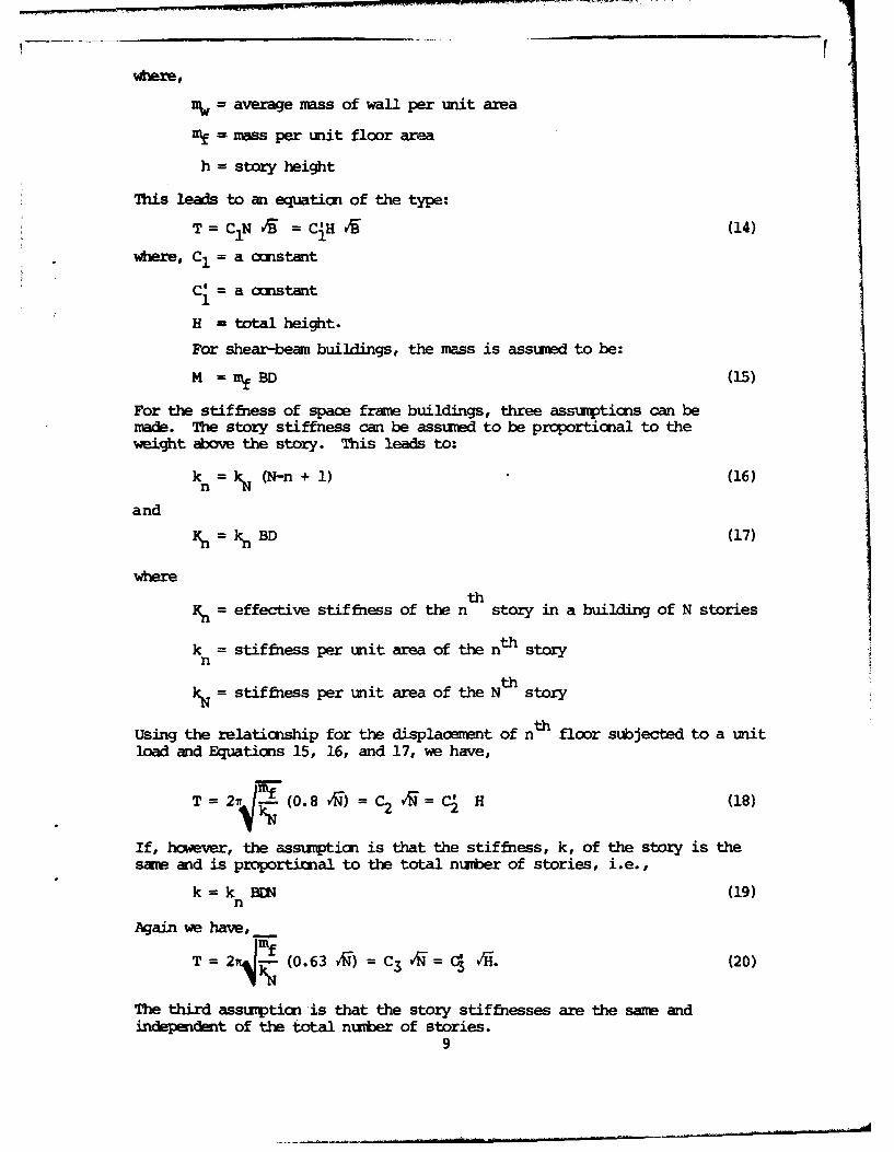
where,
= average mass of wall per unit area
mf mass per unit floor area
h = story height
This leads to an equation of the type:
T = CN Cj- (14)
where, C1 = a constant
C' = a constant
H - total height.
For shear-bean buildings, the mass is assumed to be:
M = mf BD (15)
For the stiffness of spaoe frame buildings, three assumptions can bemade. The story stiffness can be assumed to be proportional to theweight above the story. This leads to:
kn = ; (N-n + 1) (16)
and
K = k BD (17)
whereth
S= effective stiffness of the n story in a building of N stories
k = stiffness per unit area of the nth storyn
kN = stiffness per unit area of the Nth story
Using the relaticnship for the displaoement of nth floor subjected to a unitload and Equations 15, 16, and 17, we have,
T = 2n!E (0.8 v5) = C2 = C1 H (18)
If, however, the assumption is that the stiffness, k, of the story is thesame and is proportinnal to the total number of stories, i.e.,
k = k BEN (19)n
Again we have,
T = 2w4 (0.63 R) = C3 V9 = Ci rH. (20)
The third assumption is that the story stiffnesses are the same andindepedent of the total number of stories.
9
Then,
k = kN BD (21)
and
T = C4 N = C4H (22)
Considering the Uniform Building Code, the assumptionsunderlying Equations 6 and 7 can now be better understood.
From Equation 9, it can be seen that Equation 7 would givereasonable results only if the mass to wall stiffness perunit length ratio of all shear wall buildings were constant.Equation 6 assumes the relationship expressed by Equation21. Both of these assumptions are very restrictive. Infact, for shear-wall type buildings, Equation 7 as given inthe Uniform Building Code gives the poorest fit to actualdata comparing with Equations 18, 20, and 22 (46). It isprobably too much to expect from a simple relationship togive reasonable results for a variety of buildings. There-fore, recommending different empirical formulas for differ-ent assumptions about the mass and stiffness distributionof the building should lead to more reasonable results.
A plausible approach to this problem has been presentedby Salvadori and Heer (48), who proposed to calculate thenatural period by combining the effects of shearing deforma-tion, bending deformation, rocking motion as well as founda-tion translational motion. For the Alexander Building inSan Francisco, their calculations for the natural period ofvibration of the building had errors of only between 4.5% -8.7%. By using extreme values of all parameters for normalbuildings, the authors plotted two curves which envelopedall the possible periods for these structures. This methodcould be adapted to give a range of value for T rather thana single value, and thus improve the validity of empiricalformulas.
Since the response is given as an explicit function ofthe period of the structure, Equation 4 suggests the use ofa response spectrum technique in its derivation. Thereforethe following background information on response spectrumtechnique is presented (49).
For a multi-degree-of-freedom system and using theelastic modal superposition, we have the following govern-ing equation:
Y + 2X w•Y + w2 Y n (23)n n n nn n n Mn
10

in which,
Y - amplitude of mode "n"nx = damping ratio of mode "n"
S= natural frequency of mode "n"n
also,NN 2
2 .M (24)in l ýin li
NPn* = .*inpi (25)
i=l
where,
Oin = nth mode shape.
M. = ith mass
P = ith force
In the earthquake response problem, letP n* = LnVg (t) (26)
where,
V (t) = ground acceleration,g
andN
Ln M .iin (27)i=l
The solution for each mode can be written in the form of theDuhamel integral, or for earthquake response,
LnYn(t) M * Vn(t) (28)
Mn n
where,
Vn(t) f V (T)e sinw(t-T)d¶ (29)0 g
We have the following relationships and definitions:
"displacement" v(t) =. V(t) (30)
11

Ii
"base shear," Q(t) = Kv(t) Mw M2v(t) =MWV(t) (31)
"spectral density," S = Vm(32)
"spectral displacement," Sd (33)
"spectral acceleration," S = S (34)a
The effective acceleration is given by:
Lnt)=2 Yt)=nn t n MY n•)Wn V n(t) (35)
Thus the force at level "ill is
LFin (t) = MiV in(t) = Miin Yn (t) = Miin M V (36)
Then, the base shear becomes,
N N L 2Fi = .uinM. t V (t) (7Qn i Fin i iin n n n W n Vn M (37)
The maximum base shear is obtained using response spectrumsuperposition:
L 2 L 2
Q n _ - n (38)nma M* n •nvn MSan (8
Since the maxima of each mode do not occur simultaneously,the following approximation is made to find the total maxi-mum.
Qax-- Q 2+ Q 2 + ... + Q2 (39)ax 2 2 2
The above procedure is based on modal superposition andthe effects of all modes of vibration are taken into account.However, the Uniform Building Code formula for the coeffi-cient C is based on a more approximate method which only con-siders the first mode of vibration. It also assumes that thefirst vibration mode shape is a straight line from the baseto the top. For this method:
NL Mi~i (40)
i=l
NM*= Sii (41)
i=l
12

which results in:L2
=x v (42)
There is little apparent resemblance between Equation 42and the Uniform Building Code formula except for the depen-dence on the natural period (or frequency) of the building.This is a result of empirical considerations in the deriva-tion of Equation 4. Another difference is that Equation 42is a result of purely elastic analysis; therefore it givesmuch higher values than that specified in the Uniform Build-ing Code. A good discussion on how to incorporate ductilityand therefore the energy absorption capacity of buildings in-to response spectrum techniques can be found elsewhere (50).It is to be noted that the inelastic action which is takeninto account in the coefficient C is further modified byanother factor K depending on the type of structure accord-ing to its ductility.
1.2 The factor K represents the effect of the type or ar-rangement of the resisting elements of the structure, and isan indication of the structure's overall ductility. In theUniform Building Code, K varies from 0.67 for moment resist-ing ductile space frames to 1.33 for box systems and 3.00 forelevated tanks. In a dual bracing system where both shearwalls and a moment resisting space frame (to take at least25% of the total lateral force) are designed to carry thelateral loads, the factor K is taken to be 0.80. For allother buildings with normal ductility, the factor K is con-sidered as being unity.
The difference between the elastic analysis and the Uni-form Building Code recommendations is due to the effects ofinelastic action, which the code has taken into account.Equations 4 and 5 already include a "ductility factor" whichreduces the maximum response of the structure. This "ductil-ity factor" is chosen for a normal building, where the lateraldeflection is partly shear deflection and partly flexural.It is seen that for this type of building the "ductilityfactor" which is already incorporated in C is untouched (i.e.K = 1.00). However, when other types of resisting arrange-ments are used, then this "ductility factor" is modified byincreasing or decreasing K. As an example, for a ductilemoment resisting space frame, the ductility factor increases;therefore the K factor reduces (to reduce the base shear) to0.67. For specially designed dual bracing systems in whichthe space frame can take 25% of the lateral load, K is equalto 0.80. For more rigid structures such as box systems, theductility factor decreases and K increases to a value of 1.33.
13

When the structure in questimn is expected to act asstatically determinate (e.g., elevated tanks), inelastic ac-tion results in collapse; therefore for these types of struc-tures, K assumes its highest value of 3.00.
1.3 The numerical coefficients for the factor Z depend uponthe seismic zone map of the United States as given in theUniform Building Code. For locations in Zone No. 1 'Z' shallbe equal to one-fourth. For locations in Zone No. 2 'Z'shall be equal to one-half. For locations in Zone No. 3 'Z'shall be equal to one.
Seismic zoning or regionalization of the United Statesis a very difficult task and is usually based on two kinds ofobservations. The first one is a statistical approach wherethe history of earthquakes in a given location acts as aguideline to estimate the intensity and the frequency offuture earthquakes. The best source of data which is avail-able concerning seismic activity in the United States is theobservation of the frequency of small shocks for a given lo-cation. Unfortunately, a speculative correlation between thenumber of small shocks observed in a location and the maximumexpected intensity of a future earthquake can be misleading(51). Because the interest of structural engineers lies withthe maximum expected intensity, the use of small shock datain earthquake engineering is rather questionable. The secondsource of observation, on which the seismic regionalizationcan be based, is geological. Usually, both of these obser-vations have been evaluated for seismic regionalization.
In the United States seismic regionalization was at-tempted in 1950 and 1951, when the "Seismic Probability Mapof the United States" was prepared by Roberts and Ulrich(52, 53). Richter indicated, however, that this "was notstrictly a regionalization map, since it was directed toestimate risk rather than maximum intensity" (51). Againquoting from Richter, "The Seismic Probability Map was of-ficially retired in 1952, as 'subject to misinterpretationand too general to satisfy the requirements of many users.'This action was not taken in consequence of scientificcriticism, but as a result of pressure from a business groupinterested in lower ranking in their community." It is in-teresting to note that this map is still being published,with a few revisions, as a part of the Uniform Building Code.
1.4 The Uniform Building Code recommendations for the dis-tribution of the total lateral force V are as follows:
Ft = 0.004 V (h) 2 (43)
14
with the following restrictions,
Ft < 0.15V (44)
and
hFt Ofor D < 3 (45)Ft =,fo --
s
F (V-Ft)Wxhx (46)x n
W Wihii=l
where,
Ft = force at the top level
Ds= the plan dimension of the vertical, lateralforce resisting system in feet
F = force at level "x"x
Wi, Wx = weight at levels "i" and "x", respectively
hi, hx = height at levels "i" and "x", respectively
Equations 43 through 46 are not applicable for one- ortwo-story buildings, for which the distribution is assumedto be uniform.
It can be seen from these above formulas that with theexception of the top story where the force is assumed to bea little greater, the distribution is linearly increasingfrom bottom to top when the weight and story heights are thesame.
As it was discussed in item 1.1, only the first mode ofvibration was considered in the determination of the factorC. The inverted triangular distribution is a simple exten-sion of the first mode assumption. However, assuming theshape of the first mode to be a straight line is overly re-strictive. Even though the formulas are to be used for anytype of structural system, the straight line assumption canbe considered to be good only for a combination of shearwall and space frame building. For all other types ofstructural systems, the first mode shape would definitely berepresented by a curve. Furthermore, the first mode ap-proximation holds only for relatively short buildings. Fortall buildings the effects of the second and even the thirdmode of vibration should be included. The question of ac-curacy of the first mode approximation was considered by
15

(?
Clough in 1962 (54), when the errors generated by the firstmode approximation were computed for four- to twenty-story
* buildings subjected to 1940 El Centro,. 1949 Olympia, and* 1934 El Centro Earthquakes. The following conclusion were
reached:
(a) The errors given by all approximations increasewith the number of stories because the highermode contributions become more significant asthe period of vibration increases.
(b) First mode approximation shows the greatest dis-crepancies in total shear envelopes; because thehigher modes are most effective in developingshears. First mode approximation does not evenrepresent the shape of the envelope.
2. French Aseismic Code of 1964 (55)
The seismic coefficients (for masses along the height ofthe building) are given in the form of a product of four fac-tors which are discussed as follows:
2.1 The intensity coefficient, a, is somewhat analogous tothe factor Z of the Uniform Building Code as discussed initem 1.3. However, the intensity coefficient, a, is moreclosely related to the maximum response because it is a func-tion of the Modified Mercalli Intensity scale. The referenceintensity has been chosen as VIII, so that for the design in-tensity VIII, a is taken to be unity. It is assumed that adoubles whenever the intensity becomes one degree higher.This assumption is generally considered to be on the conser-vative side.
2.2 The response coefficient a depends on the natural periodof vibration and the damping of the building, and is expres-sed by the following three empirical formulas depending onthe assumed amount of damping:
(a) For common buildings and houses ("normal" damping)0.065
ý(T) = (47)
and0.05 < a(T) < 0.10
(b) Buildings with large spans and lower density ofpartitions, or with partitions tied only in places("medium" damping)
16

alT) M 0.085 (48)
and
0.065 < ý(T) < 0.13
(c) Structures reduced to a skeleton with no externalfriction (low damping)
0.095V(T) T
and
0.06 < ý(T) < 0.20 (49)
The curves for Equations 47 and 48 are not exactly re-sponse spectra. Alterations have been made in order to takeinto consideration higher modes of vibration as well as pos-sible plastic actions. For Equation 49, the curve is muchcloser to the true spectrum, so that it can be applied toflexible and slender structures, which require more explicitconsideration of higher modes of vibration.
Obviously, ý(T) is a counterpart of C of the UniformBuilding Code discussed in item 1.1. It can be seen that theFrench Aseismic Code gives comparatively more conservativevalues to ý(T) than the Uniform Building Code does to C. Infact, even Equation 48, which is for the highest damping, isstill more conservative (by 30%) than the single formulagiven by the Uniform Building Code. An extreme difference of100% is obtained in the case of a slender structure with lowdaming, since the upper limit of O(T) is 0.20 for Equation 49as opposed to 0.1 for C.
The use of a(T) seems to be more versatile and adaptablethan the coefficient C in the Uniform Building Code. Thequalitative consideration of damping is also another param-e'ter recognized by the French Aseismic Code. The effect ofdamping is recognized by the Uniform Building Code, but it isnot explicitly included.
2.3 The foundation coefficient reflects the effect of (a)the soil conditions of the immediate location and (b) thecharacteristics of the building foundation. It varies from0.8 for deep foundations on firm rock to 1.3 for piling inmoist ground. Response curves corresponding to periods lowerthan 0.5 sec. are reduced when the soil of the foundaticn isa part of a very large geological formation of soft ground.It is to be noted that this coefficient is completely ignoredby the present Uniform Building Code.
17
2.4 The distribution coefficient y is the coefficient of theterm r(T)/g in Equation 50. It depends only upon the char-acteristics of the structure and describes the variation ofthe response with respect to the level considered.
For a system with concentrated masses M(Z) and distri-buted masses m(z), the seismic coefficient a(h) similar tothe factor S defined by Equation 1 applicable to the massessituated at a height h above the base of the structure isgiven as:
h= .Y l(T) - ZM(Z)X(Z) + fim(z)X(z)dz r(T)g M(Z)X 2(Z) + fm(z)x 2(z)dz g(50)
in which,
Z, z = ordinates of concentrated masses M and distri-buted masses m, respectively
X(h) = a function giving the shape of the fundamentalmode
g = acceleration of gravity
F(T) = the maximum response (acceleration) of a singlemass oscillator of the same period T and dampingas the fundamental mode.
This coefficient, y, shows a basic difference betweenthe French Aseismic Co and the Uniform Building Code. Inthe Uniform Building Code there is no "distribution coeffi-cient" and the distribution of the lateral force is prede-termined by an inverted triangular shape regardless of theheight or the type of structure. The distribution coeffi-cient y in the French Code, however, varies from floor tofloor not depending on a predetermined function but on themass at each story and the shape of the mode (not neces-sarily linear) under consideration. In this respect theFrench Aseismic Code gives more freedom to the design engi-neer to use his judgment about the shape of the mode. Inaddition, the French Aseismic Code also, requires the con-sideration of the first three modes of vibration for slenderstructures with low damping. This also seem to be a step inthe right direction if the discussions of item 1.4 are con-sidered.
3. Standards and Regulations for Buildings in SeismicRegions of the USSR 1957 (56)
The "Standards and Regulations for Buildings in SeismicRegions" is a long and involved document and the entire docanent
18
will not Je discussed here. only exerpts frrm secticns I and III will bediscussed. Howver, the titles of all sections are cited as follows foradditicnal informaticn:
I. Earthquake Zone of an Area or a Building Site andDesign Rating of Buildings and Structures
II. Planning Cities and Towns
III. Seismic Forces for Residential, Civic, Industrial,and Farm Buildings and Structures
IV. Industrial and Civic Buildings and Structures
V. Water Works and Sewerage
VI. Highways and Railways
VII. Hydraulic Structures
VIII. Rural Structures
IX. Field Work and Control of Seismic Requirements
Seismic regionalization on the basis of maximum expec-ted intensity began in the USSR as early as 1933 (51). In1947, Gorshkov came up with the first seismic map of theUSSR (57). :Both statistical and geological data were usedin the preparation of the map, but the map was criticized byGubin on geological grounds (58). However, the map wasadopted as it was with only minor alterations (59).
The seismic regions are established according to theGEOFIAN scale which is similar to the Modified Mercalliscale. The different degrees of intensity are defined ac-cording to the amplitude of a standard pendulum. Therefore,the divisions between different intensities in the GEOFIANscale are more definite than those in the Modified Mercalliscale.
Both the Modified Mercalli scale and the GEOFIAN scalecontain twelve divisions and they both descend from theMercalli-Concani scale. The GEOFIAN scale can be summarizedin Table 1.
In the USSR regulations, buildings are classified ac-cording to their use and importance as well as their loca-tion with respect to the seismic regionalization. Buildingsare classified according to their use into four groups. Asexamples, Group I includes very large and important build-ings, large radio stations, etc. For this group the designintensity is taken to be one degree higher than that indi-cated on the seismic regionalization map. Group IV consistsof temporary light buildings. For this group the design in-tensity is given to be six regardless of the location.
19

TABLE 1
GEOFIMI Scale for Earthquakes (56)
QualitativeDescription Instrumental Amplitude
ofDivision Earthquake Range Mean
6 Strong 1.1 to 2.0 mm 1.6 mm7 Very strong 2.1 to 4.0 mm 3.0 mm8 Destructive 4.1 to 8.0 mm 6.0 mm9 Devastating 8.1 to 16.0 mm 12.0 mm
10 Annihilating 16.1 to 32.0 mm 24.0 mm11 Catatrophic > 32.0 mm ---12 Greatly
Catastrophic --- ---
The design seismic force at any point with a mass Qk isgiven by using the following formula:
S = Qxk c x (51)
in which,
x = dead load plus 0.8 times the live load at point x(except for warehouses, etc., where the live loadis not reduced).
k = seismic coefficient. For design rating 7,kc = 1/40; for 8, kc = 1/20; and for 9 kc = 1/10.
B = dynamic coefficient.
_ 0.9 (52)T
and 0.6 < a < 3.0
= a coefficient which is a function of the deforma-tion curve resulting from free vibration, and ofthe position of the load Qx within the structure.
xJ
nq1Xk) (Q5q 3
4x n (53)n Qjq2 (x.)
j=l
where q(xk) and q (xj) represent deflections at levels k andj, respectively.
20
For normal buildings, only the first mode of vibrationneed be considered. For slender and flexible structures, thefirst three modes must be considered, and a is multiplied by1.6.
The similarities between the above regulations and theFrench Aseismic Code are quite obvious. Therefore, compari-sons and discussions which were carried out in section 2 willnot be repeated here.
One of the strongest points of the USSR Regulations isthe attention given to seismic regionalization. The use ofthe more exact GEOFIAN intensity scale and the combined sta-tistical and geological data have resulted in a more scien-tifically sound seismic regionalization.
Another new item in the USSR Regulations is the incor-porating of the use or the importance of the building intothe seismic coefficient kc. It seems to be desirable to re-duce the risk where the building is massive and important andits collapse may involve a great consequence in the loss oflife and money.
4. Aseismic Provisions for the Federal District, Mexico (60)
According to the subsoil characteristics, the FederalDistrict is divided in two zones in accordance with the chap-ter on foundations. In addition, buildings are classifiedinto three groups, A, B, and C, depending on their use andimportance. Group A includes government municipal and publicbuildings, hospitals, museums, schools, stadiums, etc. GroupB consists of private habitation and public places where con-glomerations of people are uncommon (office and industrialbuildings, restaurants, gas stations, etc.). Isolated andunoccupied buildings are in Group C. Another classificationis made according to the structural characteristics. Threetypes are thus classified. Type 1 calls for framed struc-tures in which the frame is designed to take 50% of the shear.Type 2 consists of structures where the frame is designed totake 25% of the shear. Type 3 includes water tanks, chimneystacks, one column structures, etc.
The base shear coefficients are tabulated for group Bbuildings. According to the zone and the type of structure,
this coefficient varies between 0.15 and 0.04. These tabu-lated values are to be multiplied by 1.3 for group A build-ings. On the other hand, Group C buildings (mostly unoc-cupied, isolated buildings) do not require aseismic design.
21
Three different types of analyses are suggested: sim-plified, static and dynamic. The selection of the methoddepends on the problem at hand and is described in detail inthe code. The simplified method includes buildings withheight to length ratio of not more than 1.5 plus other re-quirements. The static analysis also assumes the invertedtriangular shear distribution along the height of the build-ing.
For dynamic analysis a coefficient "a" is defined as
follows:
(a) In the zone of low compressibility,
for T < 0.5, a = 1.0 (54)
for T > 0.5, a 0.5 (55)
(b) In the zone of high compressibility,
for T < 1.0, a = 0.5(1+T) (56)
for 2.5 > T > 1.0, a = 1.0 (57)2.5
for T > 2.5, a 2 T (58)
For the purpose of computation, it is assumed that the groundsuddenly undergoes a constant acceleration, which is equalto (ag) times the base shear coefficient. It is to be notedthat the dynamic analysis requires the use of the root-mean-square of the responses corresponding to each mode.
One of the new items in this code which has not beencovered so far in the codes already mentioned is the sug-gested three methods of analysis for different conditions.This permits the mode to be simple for simple cases and elab-orate and not too simplistic for buildings which requirespecial attention. Another new point is the superpositionof the modes of vibration of the structure by the root-mean-square method. This criterion is based on probability anal-yses (61).
5. Earthquake Resistant Design Provisions of Other Countries
In the preceding sections 2 through 4, earthquake regu-lations of France, the USSR and Mexico were discussed andcompared with the recommendations of the Uniform BuildingCode. In this section the provisions of the building codesof four more countries (Romania, Japan, Turkey, Israel) willbe mentioned. However, a lengthy discussion or a comparisonis not undertaken because the recommendations of these codesare qualitatively covered in the three codes which have been
22

menticned already. The main reason to choose the codes dis-cussed in sections 2 through 4 as a basis for comparison withthe Uniform Building Code was due to their uniqueness as wellas their accessibility.
The following will then be a summary of the earthquakeregulations of the aforementioned countries concerning thetotal lateral force and its distribution.
5.1 Romanian Regulations for Aseismic Design* (62)
The shear force S is the product of the total weight Qand the seismicity coefficient c. This seismic coefficientis a product of five parameters.
c = ks'n8"6 (59)
with the restriction,
c < 0.02 (60)
where,
k = indicates the seismic intensity based on theModified Mercalli scale
n = depends on the soil resistance
8 = a dynamic coefficient indicating the responsespectrum (acceleration)
0.9 (61)
6 = a correction coefficient compensating for thesingle degree of freedom assumption and given by,
h[[Qkq k]2
'~ Q~~] 2 (62)n h 21Qk {Qk2
where,
n = number of stories
h = story under consideration
qk = the deflection of the multi-degree of freedom sys-tem for the considered mode of vibration
Qk = the mass of the considered point cf deflection
*Note: These regulations were established taking into con-sideration the different codes used in other countries,especially the USSR and USA.
23

= a measure of damping
The distribution of this shear force is given by:
Sk = Sn (63)SQk qk
where qk is the deflection of the point k under the Qk load-ings. For simplification, qk can be taken as a parabola.
5.2 Some Recommendations from the Japanese Building Code (63)
The seismic force is calculated by multiplying the sumof dead and live loads with the coefficient of horizontalforce, which is not an explicit function of period T. It istaken to be 0.2 for buildings up to 16 meters, then 0.01 isadded to the coefficient for each additional 4 meters above16 meters. For wooden buildings on soft soil, water tanksand projected chimneys, this coefficient is increased to 0.3.
A reduction coefficient which can be used to reduce thecoefficient of horizontal force is designated for combinationof type of construction and the soil conditions.
Table 2
Reduction Coefficients in Japanese Code (63)
Type ofCost.
md of R/C orround Wood Steel Composite
Kind 1* 0.6 0.6 0.8
Kind II** 0.8 0.8 0.9
* Kind I: Ground consisting of rock, hard sandy gravel,etc. classified as Terhary or older strata overa considerable area around the structure.
**Kind II: Ground consisting of sandy gravel, sandy hardclay, loam, etc. classified as diluvial, orgravelly alluvium, about 5 meters or more inthickness, over a considerable area around thestructure.
24
Another table is provided to reduce the coefficientfurther either by 0.8 or by 0.9 depending on the location.This reduction is a result of seismic regionalization.
5.3 Regulations for Construction in Regions of Hazard inTurkey (64)
The total seismic coefficient C is made up of four dif-ferent coefficients.
C = C0aa* (64)
C0 = coefficient of seismic regionalization and can
take on three different values
a = a coefficient of foundation soil conditions
Scoefficient of building importancep= dynamic coefficient
for T < 0.5, ' = 1.0 (65)0.5
for T > 0.5, 0 T5 (66)
and
< 0.3 (67)
The story weights are calculated according to the form-ula:
Wi = Gi + nP.
Wi = total weight of story "i"
Gi = dead load of story "i"
P. = live load of story "i"
n = is taken to be 1 for public buildings and 0.5 forothers.
The total shear is to be distributed according to thefollowing formula:
WihiF. = F 11 (68)1 nl
i Wihi1
F. = force at story "i"1
h. = height of story "i"
25
5.4 Israel Standard Code Seismic Loads on Buildings
(Proposed) (65)
The total horizontal force H is calculated by:
H = C(G + aP) (69)
where,
C = depends on the seismic region (there are two re-gions), type of building and foundation soil con-dition (six combinations are considered)
G = dead load
P = live load
S= varies from 0 to 1 depending on the importance ofthe structure
Overturning Moment
The following are the recommedations of the 1967 Uniform BuildinaCode (without revision) concerning the cmputation of the overturningrmmnts. For the base of the structure the overturning moment M is
given by:
nM =J(Fthn + F ihi) (70)i=l
0.5 (71)
and
0.3 < J < 1.00 (72)
The overturning moment at level "x":
n= Jx[Ft(hn-hx) + 7 Fi(hi-hx)] (73)MX JX ~hx) +i=x3,.
Jx = J + (l-J) (hn) (74)
where all the symbols have been defined in section 1 of thisPart.
It can be seen that the overturning moments are calcu-lated statically from the story shear forces reduced by thefactor Jx" The reduction factors Jx and J for the overturn-ing moment at the base decrease as the period of vibration
26
of the building increases (or as the building gets tallerand more slender). Assuming that T = 0.1N, where N is thenumber of stories of the building, we get the following ap-proximate relationships: J = 1.0 for a three-story building,J = 0.5 for a ten-story building and J = 0.33 for an eighteenstory building. Justifications for this reduction for moreslender buildings are qualitative in the following manner(47, 50). For low buildings (i.e., short T) the assumptionthat the structure acts as a cantilever is a good one. Butthe application of this concept to tall buildings is over-conservative, because maximum total moments on a sectionthrough the building and maximum shears on such sections donot occur for the same combinations of modal components. Theformula for the distribution of overturning moment providessimply for a straight line variation of moment from M at thebase to zero at the top, even though this is not consistentwith the static moments computed from the lateral force dis-tribution. However, it is reasonable for slender structures(50).
Another point made is that no tall building has been ob-served to simply "topple over" during an earthquake, whereasfor shorter buildings this is not an uncommon occurrence.However, this argument cannot be considered valid because thenumber of observations on tall building behavior duringearthquakes is still limited. In addition, the fact that notall building was observed to have "toppled over" does notmean that the overturning moments do not excite a differentform of failure.
The following comments against the code formulas weremade by Derrick in his commentary to Reference 47. "In theSEAOC proposal the reduced values Fx are used to compute M,the overturning moment. The true value of M is the sum ofthe moments of the equivalent inertia forces capable of pro-ducing the maximum dynamic distortion at maximum response.The results of both Fx and Fxn act at approximately 2/3 ofthe height of the structure and from the ratio Vn/V the Fxhxis (V /V) (Fxnhx), where Fxn denotes the distributed shearof ntfl mode on xth story. Hence to evaluate the maximumoverturning moment from Fx, there should be a correctionfactor increasing the Fxhx by (Vn/V). The SEAOC proposalprovides a correction factor, but it decreases the summationby J = 0.5/ 3VT2 with limits 1.0 to 0. 33." Derrick furthercomments that the factor J moves the position of EFx to apoint lower than what the triangular distribution assumptionwould predict. As an example, the triangular distributionassumption would place the resultant at 2H/3. However, withthe use of J-factor, the resultant is placed at 2H/9. Der-rick claimed that this difference was not adequately ex-
27

plained.
In the above discussion the subscript "n" refers to thedynamic analysis response and therefore Vn/V is the ratio ofthe shear value obtained from a dynamic analysis to the rec-ommended SEAOC value.
In an analytical study, Bustamante calculated the ratiosof dynamic to static overturning moments (66). Both directaddition and the root mean square values of the spectralsuperposition were computed. These ratios were then comparedwith the J factor of the Uniform Building Code. It was con-cluded that there could be large differences between the com-puted ratios and the reduction factor of the SEAOC code. Theerrors involved could be as large as 100% even for moderateperiods of less than 0.35 seconds. However, all errors werefound to be on the safe side. The considerations were formu-lated by assuming that there were no errors in the estimationof T. As far as the distribution was concerned, the authorconcluded that "the ratio of static to dynamic moments in-creases pronouncedly towards the top. The tendency is op-posite the one concerning shears, for which the larger fac-tors of safety were at the bottom." This study by Bustamanteseems to confirm the qualitative arguments of Clough (47) andBlume, Newmark and Corning (50).
The foreign building codes which were cited previously donot provide any regulations with regard to the overturningmoment. Therefore it is assumed that the overturning momentsare simply calculated from the story shears for which theprovisions of these codes are extensive. One exception isthe "Aseismic Provisions for the Federal District of Mexico"(60). But even in this code the provisions for overturningmoment are restricted to the "Static Analysis," and are asfollows: "For design purposes, overturning moments may bereduced, but for each frame or group of resisting elementsit shall not be taken smaller than the design shear at theelevation considered times its distance to the center ofgravity of all the corresponding masses above."
Torsion
In the Uniform Building Code, the static method is usedto calculate torsional moments. Torsional analysis is re-quired for all buildings (symmetrical buildings included)and the minimum design eccentricity is to be taken as 5% ofthe maximum dimension of the building.
Considering the importance of the problem, the UniformBuilding Code treats it very lightly. Four references will
28

r
be cited below about the problem of torsion and some of theirimportant observations and conclusions will be quoted. Onearea of unanimous agreement is the importance and the poten-tial danger of the problem.
The following observations were made by Housner andOutinen (67):
"It has been shown that an unsymmetrical buildingundergoing torsional accelerations can be expectedto sustain stresses in the more flexible wall thatare higher than those predicted by the customarystatic method of analysis. If the objective of thedesign is to keep the maximum stress within the usualallowable limits, a correction should be made to theresults given by the usual static method of analysis.On the other hand, if the objective of the design i_4to provide a certain ultimate strength, the relativerigidity of the wall is not so important a factor asis the ability of the wall to absorb energy."
Similar and additional conclusions are also reached byBustamante and Rosenblueth (68).
"(a) Dynamic eccentricity may exceed staticallycomputed values. The excess is particularly im-portant when the polar moments of inertia are closeto their critical values; these are attained withinthe range of usual characteristics of buildings.
Dynamic eccentricity is defined as follows:
15/2ed (a+ V2 2 (75)
where,
M. = torsional moment in the ith mode
Vi = shear force in the ith mode of a staticallyeccentric structure.
"(b) A rough estimate of torsional dynamic effectsin multistory buildings can be obtained from theresponse of a single story structure with similarcharacteristics.
"(c) Excessive dynamic eccentricity due to close-ness to the critical polar moments of inertia canbe Weatly reduced by changing the critical values.
29
This may be accomplished by increasing thestiffness of perimetral frames."
From these observations we can conclude that the "core"type buildings where the resisting elements are not at theperimeter of the structure are more susceptible to failuredue to torsion. This effect should be incorporated in therecommendations of building codes.
Shiga (69) concurs with Bustamante and Rosenblueth inthe equivalent single story concept and further adds that"It should be noted that when the torsional rigidity is lessthan the lateral rigidity the fundamental vibration is rota-tional and torsion is serious; when the building is not rigidagainst the ground motion, the torsion becomes more seriousand vibration pattern becomes more complicated." In additionSkinner, Skilton and Laws add that close torsional and trans-lational periods are dangerous (70).
In nearly all the foreign codes cited before, torsion ispassed rather lightly and in none is a dynamic torsion anal-ysis suggested. In the Aseismic Provisions for the FederalDistrict of Mexico (60), the torsional eccentricity is to becalculated for all stories and the design eccentricity is tobe 1.5 times the computed value plus or minus 0.05 times themaximum plan dimension. The 1.5 factor is based on Housner'ssuggestions for single story buildings (67).
Allowable Stresses
The ACI and AISC codes provide for a 33-1/3% increase inthe allowable stress of concrete for dynamic loads (wind andearthquake) in Article 1004 (71). This increase in the al-lowable stresses (both concrete and steel) has also beenadopted by the Uniform Building Code. Also for the ultimatestregth design of ductile reinforced concrete nrment resisting space framnesin seismic zcnes 2 and 3 the ultimate capacity U is given by:
U = 1.40 (D + L + E) (76)
or
U = 0.90 D + 1.25 E (77)
whichever is grei er. Where,
D = dead load
L = live load
E = earthquake load
U = ultimate capacity
30

The building codes all around the world have recognizedthe increase in the allowable stresses of different materialsunder temporary loads such as wind and earthquakes. However,the magnitude of the increase varies greatly.
In the USSR a service factor of 1.4 is given for steeland wooden structures,l.2 for reinforced concrete and 1.0 forprestressed concretes. A service factor of 1.4 is equivalentto increasing the design strength of the member by 40% (fromtranslator's note in Reference 56).
In Turkey the increase in the allowable stresses dependson the foundation soil conditions. The increase is taken tobe 50% for good conditions and 30% for fair foundation soilconditions. If the conditions are poor, no increase is per-mitted (64). The Japanese Building Code allows an increasein the alcl-abla stresses of 50% for reinforcing steel and 100% forccncrete in reinforced ccncrete (63). Also, increases of 50% for structuraland reinforcing steel and timber, and 33% for concrete arerecognized by the Mexican provisions (60).
An interesting treatment of this problem is in theFrench Aseismic Code. There is an option of choosing one ofthe two methods suggested. The so-called "ordinary method"increases the allowable stresses for steel, reinforced con-crete and prestressed concrete by 50%. The second methodis the "state limit" method. State limit is defined as thestate beyond which the construction can no longer remain ap-propriate for normal use. This corresponds to the elasticlimit for steel structures and to the yielding of the steel.The seismic forces corresponding to the nominal design in-tensity IN are considered as being normal loads, and thosecorresponding to IN + 1/2 as being exceptional ones. Inaddition, for various types of loads, different "ponderationcoefficients" are assigned to the capacity of the structurefor inelastic action. This way, a more uniform design canbe obtained (55).
In all cases, the increases in the allowable stressesapply only to the combination of gravity and lateral loads.Also, they are given for working-stress designs. In fact,this is the basic reason for the inconsistencies in the in-crease permitted for the allowable stresses by the abovecited codes. Blume, Newmark and Corning explain these dif-ferences as follows (50):
"It can be shown that the reserve capacity ofstructural members to resist severe earthquakeloading will depend upon the additional stressrequirement to cause yielding and failure. Thus
31
a bracing member proportioned only for earthquakestress (no dead or 1 ive load participation) willtend to have less reserve strength and energycapacity than a member the size of which is de-,termined by dead and live load requirements-aswell as earthquake. The result is an inconsis-tency in the strength provided for different mem-bers in the same structure, when a working stressor even a modified working stress design proced-ure is used. A design procedure based on ultimatestrength or energy capacity would avcid these in-consistencies."
Other Considerations
1. Lateral Force on Parts of Buildings and Append&ges
The Uniform Building Code formula for the "Lateral forceon parts or portions of buildings and other structures" whichis designated by F is as follows:
pF =ZC W (78)
P ppwhere
W = the weight of the portion under considerationp
C = a coefficient given by Table 23-D of the UniformP Building Code and which varies from 1.00 for "canti-
lever parapet and other cantilever walls (except re-taining walls)" and "exterior and interior ornamen-tations and appendages" to 0.10 for "tank plus ef-fective mass of its contents, when resting on theground."
This formula is analogous to the base shear formula, butthe coefficient Cp is always equal to or greater than C.Since there is no dependence of Cp on the period of vibrationEquation 78 is a result of an equivalent static analysis.
The problem of appendages on buildings is often aserious one. The attached portions are subject to the ac-celeration of the building which in general is much largerthan ground acceleration. Normally all such appendages havedifferent periods of vibration; therefore a rigorous analysis!is generally very difficult. Another factor is that usuallythese appendages are statically determinate and thereforecannot develop much ductility,which is desirable in buildingsdesigned to resist earthquakes. This is why afactor which is equivalent toK in Equation 2 has been omit-ted from Equation 78.
32
The following conclusions are drawn about appendage be-havior during earthquakes by Penzien and Chopra (72).
(a) The two-degree-of-freedom method of analysisquite accurately predicts the maximum dynamic re-sponse of an appendage attached to the top of amulti-story building even when its period of vibra-tion coincides with the fundamental period of thebuilding; thus, the availability of two-degree-of-freedom response spectra makes this method of anal-ysis practical.
(b) The single-degree-of-freedom method of analysisbecomes considerably in error when the period of theappendage is near the period of one of the lowerbuilding modes; therefore, this method of analysisshould not be used in such cases.
(c) To greatly reduce the seismic forces in an ap-pendage, it should be designed so that its periodof vibration differs considerably from the firstmode of vibration of the building and also does notcoincide with other lower building modes.
(d) The seismic forces developed in an appendage,even when designed in accordance with the recom-mendations of (c) above, are larger than code values;therefore, the desirable effects of inelastic defor-mations must be considered as a standard practice inthe design of buildings.
With regard t- this point there is not much that theother international codes would contribute since their pro-visions are generally in the same form as that of the Uni-form Building Code. The Turkish Code gives a coefficient asa function of, in fact three times, the coefficient C forthe whole building (64). The code of Israel specifies a co-efficient C which can be as much as twenty times the coef-ficient C o? the whole building, although the relationshipis not explicit (65). The USSR provisions specify the prod-uct On (see section 3 on page 18 for definitions) to be atleast five for portions of buildings and attached structures.
2. Effect of Vertical Seismic Force
In most building codes, including the Uniform BuildingCode, the effects of the vertical seismic force are totallyneglected. Generally the reasons given for ignoring thevertical acceleration are: (a) the large safety factor(1.65) which the building is designed for in the vertical
33
direction, (b) the general acceptance of the fact that thevertical acceleration is considerably less than the hori-zontal accelerations, and (c) rareness of failure due tovertical acceleration from observations at the field. Allthese reasons, however, are delusive and at best simplistic.It is true that most building structures are very stiff inthe vertical direction and for this reason the dynamic ampli-fication in the vertical direction is almost negligible.Therefore, the axial stresses in the vertical members usuallyare not critical owing to the factor of safety. However, themain problem is not one of stresses but one of dynamic in-stability. The general notion that the vertical accelerationis considerably less than the horizontal acceleration is alsofalse. Obviously the average intensity of the vertical andhorizontal components of an earthquake depends upon the re-lationship between the epicentral distance to the seismographand the focal depth. If these two distances were equal, theaverage intensities of the vertical and horizontal componentswould also be equal. Therefore the problem is magnifiedespecially for deep focus earthquakes. However, this rela-tionship can only be assumed for the average intensities.For the extreme values of acceleration such simple relationsdo not hold, since the vertical and horizontal accelerationsare actually components of a random process. From the datathat he takes from Housner (73), Despeyroux points to thisfact in the following way (55):
"At a distance of 48 km. from the epicentre of theEl Centro earthquake of 1940, the focal depth being24 km., the maximum vertical acceleration was 60%of the maximum horizontal one; and for the Taftearthquake of 1952, it was also 60% at a distanceof 64 km. for the same focal depth of 24 km."
Therefore, if the failure criterion is taken to be the maxi-mum value and not the cumulative effect, then even for shal-low earthquakes and considerable epicentral distances thevertical acceleration cannot be neglected in comparison tothe horizontal component. In fact, for a stability analysisthe maximum value would be the failure criterion. As forthe lack of evidence that failure does not occur due tovertical acceleration, the following argument can be pre-sented. First, the amount of data that we have about thefailures during earthquakes is not enough to exclude anymode of failure. Second, the evidence of the Good Fridayearthquake of Alaska as well as that of Venezuela are suf-ficient to conclude exactly the opposite (74). However,even if there were no evidence whatsoever about stabilityfailure due to vertical earthquake acceleration, this prob-lem still cannot be discarded. The problem is a coupled one
34
between flexural lateral deflection and axial vibration.Therefore the transfer of energy from one mode to the otheris quite probable. In fact, it has been shown that theenergy of one mode can almost be totally transferred intothe other one (75). Therefore, a seemingly lateral failurecan actually be induced by vertical forces. This is nothingnew, and it is a natural outcome of any coupled system.
As was mentioned earlier, most codes do not include anyprovisions for vertical forces. Two exceptions are theRomanian and the French Aseismic Codes. The recommendationsof the Romanian regulations for aseismic design read as fol-lows (62): "Besides horizontal forces, supplementary verti-cal forces are also taken into account by increasing thevertical forces from 25 to 100 per cent according to thedegree of intensity." Also the recommendations of theFrench Aseismic Code are given as (55):
"Vertical and horizontal seismic forces are con-sidered to act simultaneously. As the maximumhorizontal and vertical responses are not likelyto occur at the same time, the vertical componenttaken into account is only a part of the maximumresponse. However, for structural elements inwhich lateral forces are of no concern, like vault-ties and cantilevers, higher values might be im-posed, with the idea of penalizing projectedfacades and so on."
35
PAR III: POSSIBLE IMPROVEMENTS IN CODE FORMAT
General
The Uniform Building Code (8) specifies equivalentstatic loads for design. Although these static loads arebased on dynamical considerations, discrepancy in their ac-curacy is noted in many areas. For example, Kanai andYoshizawa (76) have shown that the equation given in thebuilding code for the natural period of vibration of build-ings is not in agreement with experimental results. Simi-lar conclusions have been drawn by Arias and Husid (77).Blume (12) has shown that the cumulative displacement due todynamic loads could critically exceed static load deflec-tions specified by codes. A review of existing codes asgiven in Part II indicates that the Uniform Building Codetakes into account the dynamic effects in a different man-ner from French and other codes. At the present time, thereis a considerable amount of research work being done inearthquake engineering (78). Nevertheless, the current re-search programs are primarily concerned with specific prob-lems. It seems to be desirable to review the philosophiesbehind these design codes.
In Part III, some design philosophies including theconcept of structural control are examined in the contextof earthquake engineering. Design methodologies are alsoreviewed with emphasis on the design tree and the fullysystematic method, which are later applied to the formula-tion of a new code format. Moreover, the expected problemsin the implementation of the proposed code format are listedalong with an outline of necessary procedures for their so-lutions.
Some Design Philosophies and Methodologies
According to Asimow (79), there are the following threeparts in a philosophy of engineering design:
1. a set of consistent principles and their logicalderivations,
2. an operational discipline leading to action, and
3. a feedback mechanism measuring the advantages,detecting weakness, and pointing out the di-rection for improvement.
36
The principles and their logical derivations being usedin support of existing design codes are primarily determin-istic in nature. Whenever it is possible, dynamic effectsare represented by "equivalent static forces." Moreover,the seismic structures are designed to remain elastic ornearly so under the influence of moderate and frequentearthquakes, but to allow local yielding without collapsingunder severe and infrequent earthquakes (50, 80). However,the effect of repeated plastic deformation is known to becumulative (81, 82). Recently, it was found to be possibleto have low-cycle fatigue failure of structures under earth-quake loads (18).
The relations between pure research, applied research,and practical applications are given by the Committee onEarthquake Engineering Research as shown in Figure 1 (2).Because of differences in objectives, the pure research inseismology does not contribute directly to engineering de-sign under earthquake conditions. As an example, thestructural engineer is interested to know the structural de-formations caused by strong-motion earthquakes, which can-not be measured with overly sensitive seismographs utilizedby seismologists. In general, however, research results invarious related specialties such as seismology, qeology, andgeophysics are helpful to earthquake engineerin.g ii terms ofbasic information such as (a) the locations, ma:-itudes, andfrequencies of occurrence of earthquakes, (b) the distinc-tion between active fault zones and potentially activefaults, (c) the locations and amounts of surface fault move-ments, and (d) the nature of crustal deformation (2). Theapplied research as shown in Figure 1 may be described as afeedback mechanism, which serves to point out the directionfor improvement of the practical application. A design codemay be considered as a component of practical applicationsas shown in Figure 1.
Several attempts have been made to "control" the struc-tural response recently. These include (a) the applicationof "static control" by ZuK (83), (b) "active systems" byWright (84) and Nordell (85), and (c) "adaptive systems" byYao (86). As an example of the adaptive system, the bi-linear system was studied is some detail (34, 87, 88).Along the same line of thought, a statistical study of pas-sive motion-reducing devices in earthquake engineering wascompleted very recently (89). While these studies indicatepossible improvements in the seismic structural design, theavailable results are not yet directly applicable.
Generally speaking, specifications refer to (a) func-tional requirements and (b) physical limitations in the en-gineering design (90). This information can be provided by
37

z
U z a 0 1
0 r. 5J
Z- oZ a zg. 1.- 0, LL 0 W Ux
4 0 L
31 2
.JIa ro
CO 14w 2O- C
IA) Wj.... U) ~ ~ ON4t zw' $
w w 00 0~ 0
WIL4E 04 r
a.~t Co-I-0.0 00
4U) 0
rd u
IL~
CD 0 w H0w N0 I-- *r4(3 w 0 0
38
clients, authorities or agencies concerned with publicsafety, and engineering organizations. In earthquake en-gineering, design specifications have been proposed by pro-fessional engineering organizations such as the StructuralEngineers Association of California (47) and adopted as apart of the Uniform Building Code (8). The guidance forthe design of seismic structures is also given in the formof manuals as the one prescribed by the Departments of theArmy, the Navy and the Air Force in 1966 (10).
A comprehensive summary of design methodologies isgiven by Eder (91). These include (a) expenses, (b) modi-fication and running redesign, (c) checklists, (d) designtrees, (e) the fully systematic method, and (f) the systemsearch methods. In this section, the design trees and thefully systematic methods are examined in some detail, be-cause they are used in the development and presentation ofthe new code format.
In engineering design (92), the cyclic design sequenceof (a) analysis of the problem, (b) proposing solutions, (c)delineating these solutions, and (d) modifying them can beplotted as a design tree as shown in Figure 2, where aproblem is denoted by a vertical line and a solution is de-noted by a slanting line. The tree is started with a state-ment of the primary problem, which is referred to as thezeroth order, Qo. The alternative solutions, first order,are represented by slanting lines A1 , A2 , etc. For eachalternative solution, such as A2, there may be several prob-lems to be solved, i.e., Q21, Q22, etc. Any one or moreof the alternative solutions are sufficient to solve theproblem. On the other hand, it is necessary to solve allproblems before a lower order alternative solution is ob-tained. As an example, the bold lines in Figure 2 indicateone possible set of solutions.
In the fully systematic method, a list of factors rele-vant to the problem or its solution factors must be decidedin the beginning. It is important to include all ideaswithout criticism and to allow duplications. Each factor,described by a single statement, should be numbered in theorder of appearance. Furthermore, any factor that containsa possible solution of a sub-problem should begin a newcategory. Eventually, all factors must be classified intoa set of categories. The influence of one category uponanother can be studied with the use of an interaction matrix,which can be transformed into interaction nets. The result-ing interactions can now be transformed into performancespecifications, which are used to define performance (e.g.,"a column must support the floor load", not "a colunn must be
39
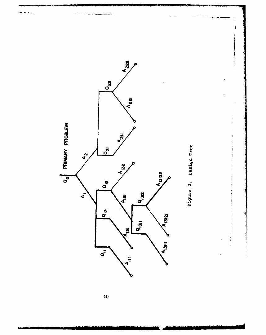
NONt
aC
N0
404
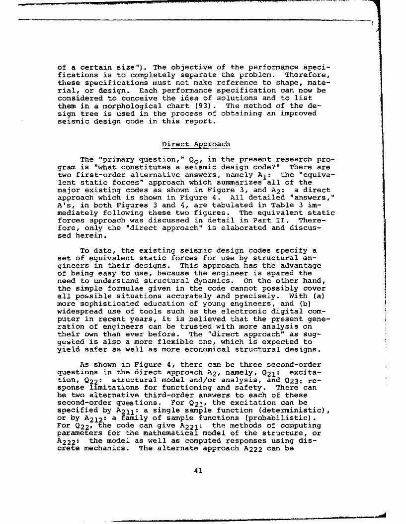
of a certain size"). The objective of the performance speci-fications is to completely separate the problem. Therefore,these specifications must not make reference to shape, mate-rial, or design. Each performance specification can now beconsidered to conceive the idea of solutions and to listthem in a morphological chart (93). The method of the de-sign tree is used in the process of obtaining an improvedseismic design code in this report.
Direct Approach
The "primary question," Qo, in the present research pro-gram is "what constitutes a seismic design code?" There aretwo first-order alternative answers, namely A1 : the "equiva-lent static forces" approach which summarizes all of themajor existing codes as shown in Figure 3, and A2 : a directapproach which is shown in Figure 4. All detailed "answers,"A's, in both Figures 3 and 4, are tabulated in Table 3 im-mediately following these two figures. The equivalent staticforces approach was discussed in detail in Part II. There-fore, only the "direct approach" is elaborated and discus-sed herein.
To date, the existing seismic design codes specify aset of equivalent static forces for use by structural en-gineers in their designs. This approach has the advantageof being easy to use, because the engineer is spared theneed to understand structural dynamics. On the other hand,the simple formulae given in the code cannot possibly coverall possible situations accurately and precisely. With (a)more sophisticated education of young engineers, and (b)widespread use of tools such as the electronic digital com-puter in recent years, it is believed that the present gene-ration of engineers can be trusted with more analysis ontheir own than ever before. The "direct approach" as sug-gested is also a more flexible one, which is expected toyield safer as well as more economical structural designs.
As shown in Figure 4, there can be three second-orderquestions in the direct approach A2 , namely, Q21: excita-tion, 02?: structural model and/or analysis, and Q23: re-sponse limitations for functioning and safety. There canbe two alternative third-order answers to each of thesesecond-order questions. For Q21, the excitation can bespecified by A2 1 1 : a single sample function (deterministic),or by A2 1 2 : a family of sample functions (probabilistic).For Q22, the code can give A2 2 1 : the methods of computingparameters for the mathematical model of the structure, orA2 2 2 : the model as well as computed responses using dis-crete mechanics. The alternate approach A222 can be
41
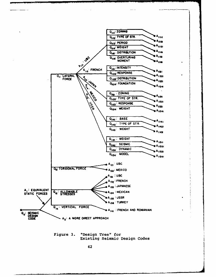
01111, BASENING 1
014:TYPE OFSR. A11421
0114 WEIGHT A13
Olli; DITRIBTIONA 11141
1151,b ~ DYMNAMI
A 1 1
/'p":'A FA 132: FR NENCHT112:lA, 2 ; RESPONESE All
Ail EQUIVALENTalSTATIC FORCES DITIBTO Al 13E
~~16 A1 f1 FREONCINDG OANA
A132 MOPE DIEC APPROAC
Fiur 3. REDesign Tre or2
422 A12
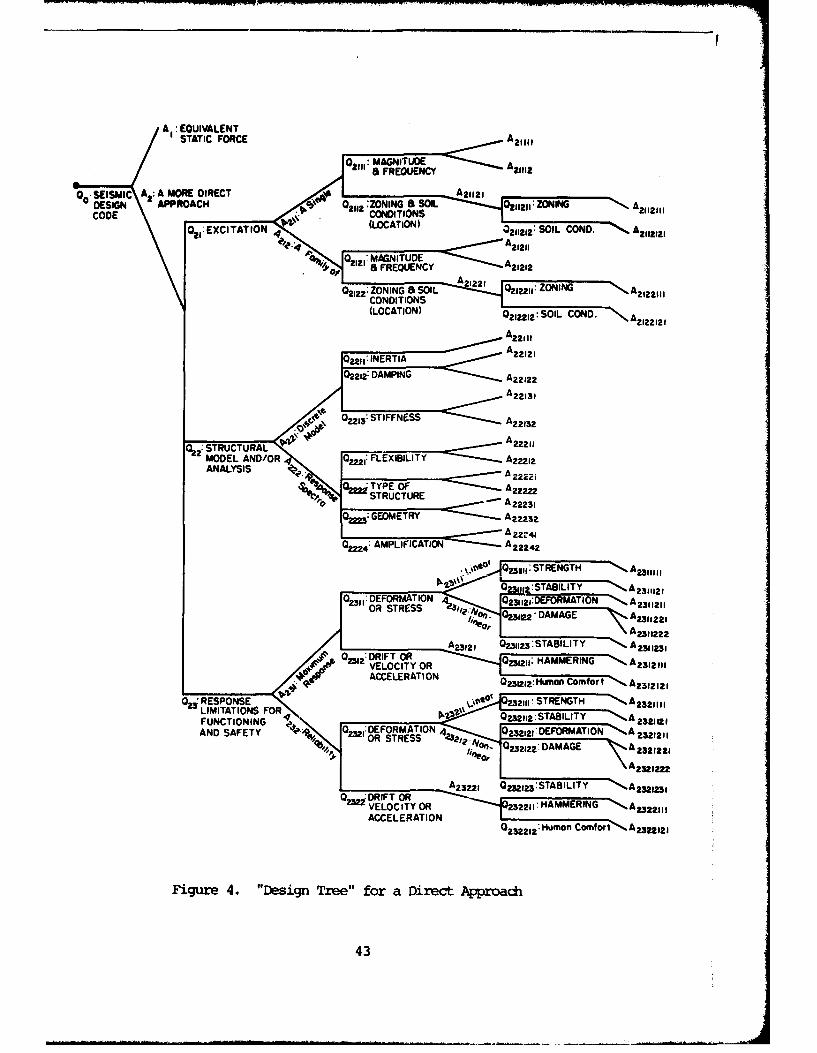
A EQUIVALENT
00ý SEISMIC A a: A MORE DIRECT .. 2.~j 1 1OL 2121:OIN2111
DEIN APOCOj 2112:ZaNINGSSl A 122* 021~121: ZONING A2112111
Oý,ECTIN4(LOCATION) 0211212: SIL COND. A2122121
A' 02211: INERITIA E A221211
02212: DAMPING A2L 212211 OIGA111
A221 11
C D 2213: STIFFNESS .A 22132
MODEL AND/OR 0222: FLEXIBILITY -. A22212ANALYSIS A -%. 0,ý TYPE OF A22
STRUCTURE A223Q , .: GEOMETRY A A Z213 a
A 2,4
02224: AMPLIFICATION-=:::: A222 42
V~OW 0311:STRNGTW%%,."* A2311,11,
WIp:STABILITY -- *A 23 11210231: DEFORMATION 4 0,~2 3121DIEFORMATION `%A 2311211
OR STRESS - 0231,22 DAMAGE A3,2
'IliaoT"% IA 231212 12FOR12 0I2312:STABILITY -- A2321,23
AND AFEY ~0 2 121:DRIFTORATO4 0232121DEHAMMETIONG AORS RES
2321211ýN
VELOCITY OR 21HAMRN A23 12111ACCLEAT1 ON 0 H" ofACCELERATIO Hum n Comfort A23 ,2121
Figure ~ ~ ~ ~ ~ ~ ?122 4."einTe"fr nietApod
O~zREPOSE23211 SREGTH A 3411
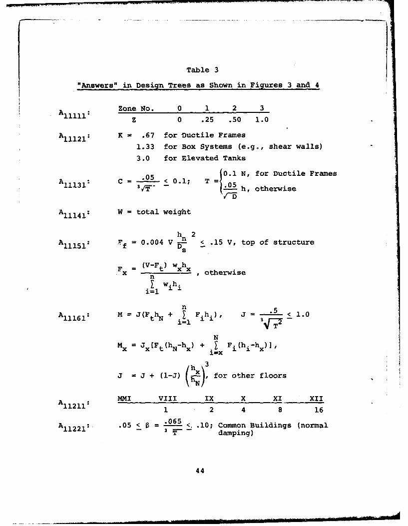
Table 3
"Answers" in Design Trees as Shown in Figures 3 and 4
Zone No. 0 1 2 311111 z 0 .25 .50 1.0
A1 1 1 2 1 : K .67 for Ductile Frames
1.33 for Box Systems (e.g., shear walls)
3.0 for Elevated Tanks
0.1 N, for Ductile FramesA~ 113 C 1.5<0.15"A11 h .05h otherwise
A11 1 41 : W = total weight
h 2AFf = 0.004 V - < .15 V, top of structure
Fx = (V-Ft) wxhx otherwisenI w.h.
n .5i=i 1T2
NMx =Jx [Ft (hN-hx) + I F i (h i-hx)]'
iNx
j = J + (l-J) for other floors
MMI VIII IX X XI XII1 2 4 8 16
A1 1 2 2 1 : .05 < 6 = 5 <..10; Common Buildings (normal121T damping)
44
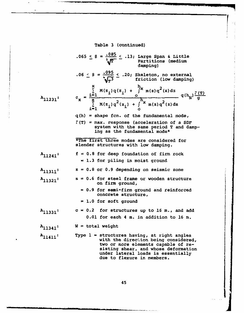
Table 3 (continued)
.065 < B = .085 < .13; Large Span & LittlePartitions (mediumdamping)
.06 8 -= 9 < .20; Skeleton, no externalfriction (low damping)
x h2SM(zi)q(zi) + x m(z)q (z)dz
A1 1 2 3 1 : X
• M(z.)q (z.) + f x m(z)q (z)dz
q(h) = shape fcn. of the fundamental mode,r(T) = max. response (acceleration of a SDF
system with the same period T and damp-ing as the fundamental mode*
*The first three modes are considered forslender structures with low damping.
A11 241 : f = 0.8 for deep foundation of firm rock
= 1.3 for piling in moist ground
A1 1 3 1 1 : z = 0.8 or 0.9 depending on seismic zone
*A11321: s = 0.6 for steel frame or wooden structureon firm ground,
= 0.9 for semi-firm ground and reinforcedconcrete structure,
= 1.0 for soft ground
A1 1 3 3 1 : c = 0.2 for structures up to 16 m., and add0.01 for each 4 m. in addition to 16 m.
A1 1 3 4 1 : W = total weight
A1 1 4 1 1 : Type 1 = structures having, at right angleswith the direction being considered,two or more elements capable of re-sisting shear, and whose deformationunder lateral loads is essentiallydue to flexure in members.
45
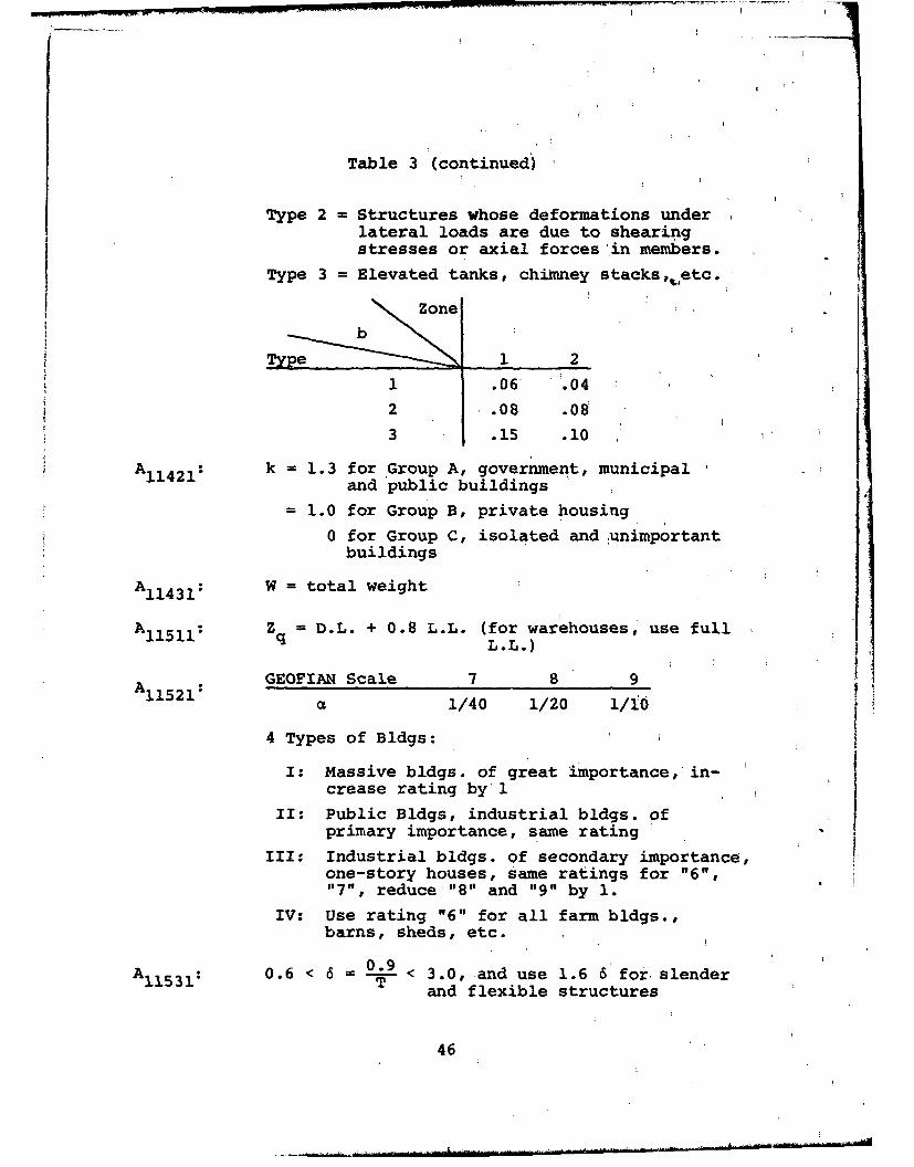
Table 3 (continued)
Type 2 = Structures whose deformations underlateral loads are due to shearingstresses or axial forces in members.
Type 3 = Elevated tanks, chimney stacks,,,etc.
gype- .1 2.06 .04
2 .08 .09
3 .15 .10
A1 1 4 2 1 : k = 1.3 for Group A, government, municipaland public buildings
= 1.0 for Group B, private housing
0 for Group C, isolated and unimportantbuildings
A1 1 4 3 1 : W = total weightAll1511: Z = D.L. + 0.8 L.L. (for warehouses, use full
L.L.)
GEOFIAN Scale 7 8 9A1 1 5 2 1 :S1/40 1/20 1/1O
4 Types of Bldgs:
I: Massive bldgs. of great importance, in-crease rating by 1
II: Public Bldgs, industrial bldgs. ofprimary importance, same rating
III: Industrial bldgs. of secondary importance,one-story houses, same ratings for "6","7", reduce "8" and "9" by 1.
IV: Use rating "6" for all farm bldgs.,barns, sheds, etc.
A1 1 5 3 1 : 0.6 < 6 0.9 < 3.0, and use 1.6 6 for slender1T and flexible structures
46

Table 3 (continued)
NSx Qiq(x )
i=lA1 1 5 4 1 : Nx N
i Qiq (x.)
use Ist mode for normal buildings, and usethe first 3 modes for slender and flexiblebldgs.
A1 2 1 : TN = SN(1.5 eN + 0.5 Bn)
shear eccentricity max. dimension
A1 2 2 : eD 1.5 ec ± 0.05 D
A 131: May be increased by 33%
A1 3 2 : May be increased by 50%
A1 3 3 : May be increased by 50% for reinforcing steel, and100% for cancrete in reinforced oncrete
A1 3 4 : May be increased by 50% for steel, and 33%for concrete
A 135: May be increased by 40% for steel, 20% forreinforced concrete, and 0% for prestressedconcrete
A : May be increased by 50% for good soil con-ditions, 30% for fair soil conditions, and0% for bad soil conditions
A1 41 : French and Romanian codes mentioned it. How-ever, it is not clear as to how to do it indesigns
A2 1 1 1 1 : Take a typical set of earthquake records,e.g., 1940 El Centro
A2 1 1 1 2 : Find the least favorable excitation, e.g.,Drenick
A2 1 1 1 2 1 1 1 : Zoning (deterministic)
47
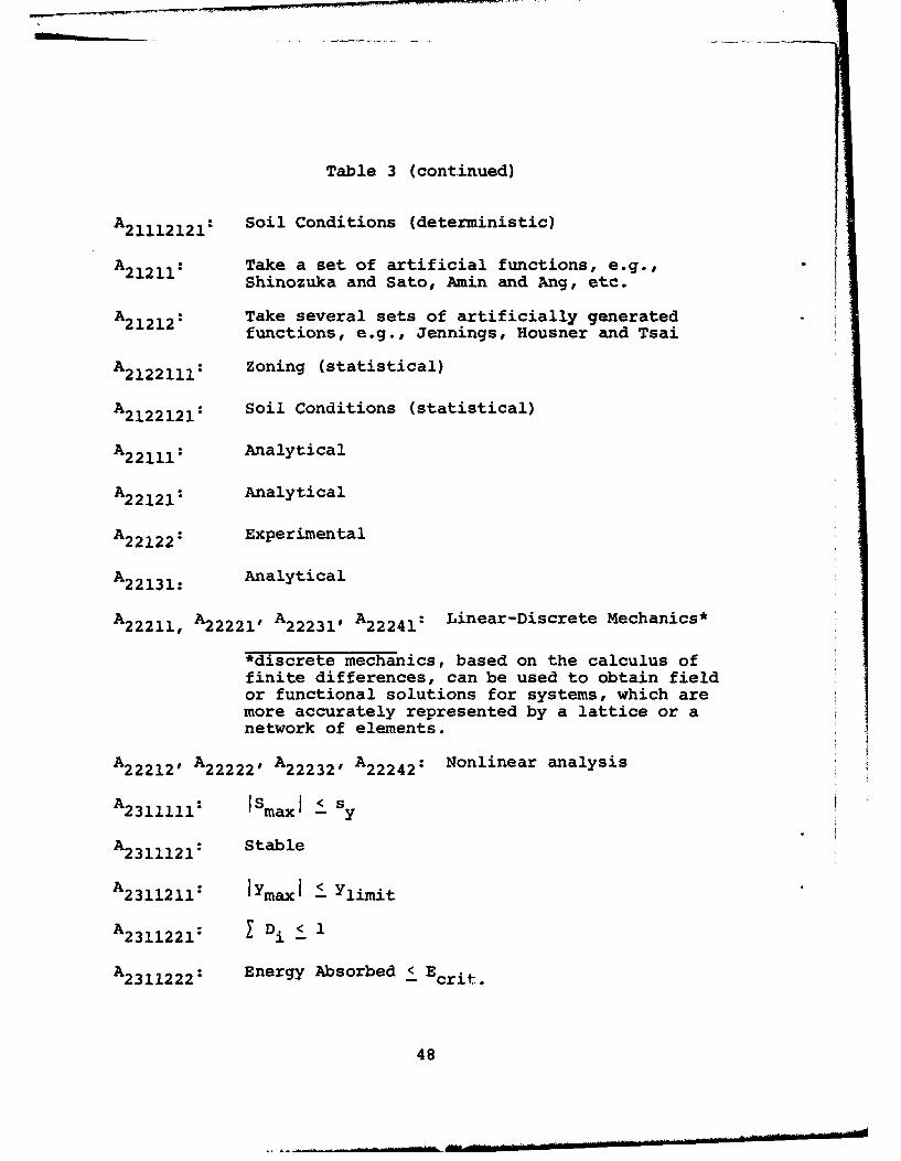
Table 3 (continued)
A2 1 1 1 2 1 2 1 : Soil Conditions (deterministic)
A21211: Take a set of artificial functions, e.g.,Shinozuka and Sato, Amin and Ang, etc.
A2 1 2 1 2 : Take several sets of artificially generatedfunctions, e.g., Jennings, Housner and Tsai
A2 1 2 2 1 1 1 : Zoning (statistical)
A2 1 2 2 1 2 1 : Soil Conditions (statistical)
A2 2 1 1 1 : Analytical
A2 2 1 2 1 : Analytical
A2 2 1 2 2 : Experimental
A2 2 1 3 1 : Analytical
A22211, A2 2 2 21 , A2 2 2 3 I, A2 2 2 4 1 : Linear-Discrete Mechanics*
*discrete mechanics, based on the calculus offinite differences, can be used to obtain fieldor functional solutions for systems, which aremore accurately represented by a lattice or anetwork of elements.
A22212, A2 2 2 2 2 , A2 2 2 3 2 , A2 2 2 4 2 : Nonlinear analysis
A2 3 1 1 1 1 1 : Smax Sy
A2 3 1 1 1 2 1 : Stable
A 2311211: lYmaxl Ylimit
A2 3 1 1 2 2 1 : I Di < 1
A2 3 1 1 2 2 2 : Energy Absorbed < Ecrit"
48

Table 3 (continued)
A2 3 1 1 2 3 1 : Stable
A2 3 1 2 1 1 1 : Hammering Prevented
A2 3 1 2 1 2 1 : Comfortable
A2 3 2 1 1 1 1 : PllSmax 1 Sy < P,
A2 3 2 1 1 2 1 : P(Unstable) < P2
A2 3 2 1 2 1 1 : P(YmaxI -- Ylimit) < P3
A2 3 2 1 2 2 1 : P(I Di 1_ 1) < P4
A2 3 2 1 2 2 2 : P(Eab > Ecr.) < P5
A2 3 2 1 2 3 1 : P(Unstable) < p6
A2 3 2 2 1 1 1 : P (Hammering) < p7
A2 3 2 2 1 2 1 : P(Discomfort) < p 8
pi's should be functions of type of structure,function (importance) of structure, consequenceof failure, material properties, etc.
considered as an intermediate code between the existing onesand that given by A2 2 1 . For Q2 3 , the response limitationsfor functioning and safety can be specified by A2 3 1: a sin-gle value (deterministic) or by a probability (probabilis-tic). The fourth-order questions related to these third-order approaches are discussed in the next section, whichalso includes fifth-order answers.
49

Implementation Problems and Possible Approaches
1. Excitation (Q2 1 )
To specify the excitation for the dynamic analysis ofstructures, time record(s) of the gound motion is.kare)needed. One possible answer, which has been used by manyconsulting engineers, is A2 1 1 11 : use a typical set ofstrong-motion earthquake records such as those of the famous1940 El Centro earthquake. An alternate approach, A2 1 1 12,is to make use of a "least favorable excitation." Drenick(94) showed that, for a class of excitation x(t) with afinite total energy M2 , (a) x(t) = (M/N)h(-t) causes theleast favorable response of a linear structure with the im-pulse response function h(t), and (b) the maximum energyresponse is MN, where
N = f h 2(t)dt
More recently, Shinozuka (94) showed how to estimate theleast favorable structural response to probabilistic andearthquake-like excitation. With digital or analog com-puters, it is also possible to apply Monte Carlo methodsusing artificially generated earthquake-like motions (27-34). All these time functions should be modified acordingto the location of the structure, which in turn can be ex-pressed as a function of the zoning and local soil condi-tions as shown in Figure 4.
2. Structural Model and/or Analysis (Q2 2 )
To analyse a structural system subjected to dynamicloads, it is necessary to have a mathematical model. Withthe recent advances in digital computation, the discretemodel is a possible and useful one (A2 2 1 in Figure 4). Fre-quently, the structure can be represented by a set of ordi-nary differential equations with parameters representingthe inertia (translational and/or rotational), the damping(linear or nonlinear), and stiffness (linear or nonlinear).Although the study of structural dynamics has reached amature stage with certain given models such as the linearshear-type building frames, theoretical and experimentalwork seems to be needed in relating these parameters to realstructures. For example, though many studies have been madeon material and structural damping (96, 97), research anddevelopment work is needed to specify damping coefficients
50
for various types of structures and partitions. Moreover,the effect of cracking or cumulative damage due to previousearthquakes on these parameters is not clearly understoodat the present time.
Ar. intermediate seismic design code might be the speci-fication of response spectra (A2 2 2 in Figure 4).
The dynamic analysis of multi-story building structuressubjected to aarthquake excitations is a complicated problemir the field of mechanics. Redundancy of such structures,random nature of loads, difficulties in determining contri-bution to damping by architectural clothing, behavior offoundation under shakedown, questions related to dynamicstability of structure, significance of nonlinear analysisaccounting for secondary stresses, and complexity of elastic-plastic behavior of frames are among problems which contrib-ute to the intricacy of the subject area.
A reasonable objective for the codes and specifica-tions in line with economic factors appears to be thatseismic design codes should provide guidelines for design ofstructures:
(a) to withstand frequent earthquakes without signif-
icant damage to structure or facings,
(b) to avoid total collapse i- major earthquakes,(c) to have sufficient stiffness to exclude sensible
vibration when subjected to wind load in normalconditions.
Subject to a few restrictions, it is feasible to pre-dict the dynamic behavior of almost any structure by the useof high speed digital computers, as well as mathematicalmanipulation. The alternative approach A2 2 2 is the de-velopment of working formulas which are simple enough to beincluded in the codes for use by practicing engineers andyet describe the dynamic behavior of a broader category ofstructures. A more detailed outline of the problem areaswill include the following:
(a) Formulas or charts for response spectrum of rigidand braced multi degree-of-freedom frames subjectto decided critical earthquake excitation to in-clude (i) displacement response spectrum in shear,torsion, or bending, (ii) shear response spectrum,(iii) bending response spectrum, (iv) torsion re-sponse spectrum, (v) determination of influenceon response spectrum (shearing forces, bending.torsion, and displacements) accounting for the
51

interaction of vertical earthquake excitation withthe horizontal accelerations, (vi) determination ofinfluence on response spectra (displacements,shearing forces, bending, and torsion) in a non-linear analysis accounting for secondary stressesand the interaction between lateral and verticalforces known as the P-A effect, (vii) dynamic re-sponses of elastic-plastic frames, (viii) deter-minaticn of time-dependent excitation most cri-
tical for any particular structure, and (ix) formu-lation of dynamic stability of structures undershakedown.
(b) Energy absorption capacity of structures:
(i) formulas for natural frequencies of vibrationof rigid and braced structures. Structures withorderly pattern and boundary conditions as well asstepped-up structures and structures with append-ages need to be considered. (ii) Influencecharts for the effects of variations in mass dis-tribution, ratio of stiffnesses, shapes, dampingfactors, sizes, etc., on energy absorption capa-city of structures. (iii) Optimum distributionof ductility to aid maximum energy absorptioncapacity.
(c) Problems related to foundations and structuralmaterials and their properties:
(i) necessary modifications in response spectradue to nature of subfoundation soil layers, (ii)liquefaction of sand and silt under intense verti-cal acceleration, (iii) the uneven foundation pro-perties and their effects, (iv) damping factorsmost closely descriptive of different construction,(v) dynamic behavior of reinforced concrete mem-bers, joints, precast or prestressed members, (vi)dynamic characteristics of multistory reinforcedconcrete buildings.
Besides those approximate methods which fall under theclassification of static equivalent methods, two methods ofsolution are available. Clough (98) suggested matrix formu-lation of each independent structure and use of generallyapplicable but somewhat lengthy computer programs. Newmark(80) formulated the response spectra for single degree-of-freedom system. Then, a multi degree-of-freedom system istreated by transformation to an equivalent single degree-of-freedom system. At the present time, this technique isbeing pursued at the University of Illinois (80).
52
Research results under the present project have indi-cated the suitability of employing an alternate approach toformulate the response spectra of multi degree-of-freedomsystems. The proposed method of solution bypasses much ofthe difficulty inherent in the earlier lines of thinking byassuming a discrete model representation of highly redundantstructures and using the calculus of finite differences andthe concepts of discrete mechanics to derive a solution.These concepts are illustrated in Appendix A, where a singlebay multi-story frame is analysed. Closed functional solu-tions are found for natural frequencies of vibration and forlateral force distribution. Furthermore, the formulation ofthe dynamic response in combined torsion and biaxial shearis given.
Earthquakes produce torsional oscillation and stress instructures due to nonsymmetric mass and stiffness prop-erties of buildings. There is, however, a lack of rationalsolutions for dynamic behavior of structures in torsion dueto complexity of the problem. The problem of dynamic be-havior in torsion and biaxial shear has received little at-tention even though the interaction of biaxial shear dis-placement with torsion is apparent. A general formulationof the dynamic response of structures in torsion and biaxial shearis given in Appendix A. This formulation as well as otherr• 3earch work based on discrete mechanics performed underthis research program serve to illustrate the potential ofthe techniques of discrete mechanics.
3. Response Limitations (Q2 3 )
For the consideration of functioning and safety ofstructures, limitations can be specified in terms of eithermaximum response (A2 3 1 ) or reliability or probability offailure (A2 32 ). These specifications can be made with theuse of statistical methods and on the basis of seismic be-havior of structures. A review of statistical methods inearthquake engineering is given in Appendix B. Moreover,the seismic behavior of concrete and metal structures issummarized and discussed in Appendix C.
When the structure behaves in a linear manner, the de-formation is proportional to either stress or strain. There-fore, strength limits can be specified. On the other hand,deformation limits must be given in the case of inelasticstructural behavior. Because the damage due to plastic de-formation is cumulative, it is also desirable to restrictthe allowable damage in building structures.
53

The structural stability under the vertical as well ashorizontal ground motions is a complicated problem. Thereappears to be little work done in this regard at the presenttime. The hammering effect of closely-spaced buildingsagainst one another should be prevented. Moreover, it isdesirable to minimize the discomfort of human inhabitantsduring earthquakes.
In both the deterministic specification A2 3 1 and theprobabilistic approach A2 1, it is desirable to make sta-tistical analysis of avalI ble data. In addition, the de-cision analysis can be a useful tool in the choice of theselimitations (99).
In Appendix B, following an introduction to basic defi-nitions, topics covered include statistics of strong-motionearthquakes, random response of seismic structures, struc-tural safety in earthquake engineering, and decision anal-ysis.. In Appendix C, a review is made of the seismic be-havior of various types of structures during recent earth-quakes. In Appendix D, a simple design problem is given as anillustraticn of the "direct approach" portion of the design tree.
54
PART IV: CONCLUSIONS AND RECOMMENDATIONS
Conclusions
A survey of existing and available seismic design codeswas made. The "design tree" technique was used to summarizethese existing specifications as well as to present possibleimprovements. Moreover, some original work has been per-formed applying the discrete mechanics to structural dynamicsas given in Appendix A. Literature reviewsof statisticalmethods in earthquake engineering and seismic behavior ofconcrete and metal structures are given in Appendices B andC, respectively.
A "direct approach" to the seismic design code is pro-posed herein. With this direct approach, the code wouldspecify (a) the excitation, (b) the structural model, and(c) the response limitations. It is believed that engineersusing this type of code will be able to design buildingstructures in a more precise, realistic, and economic manner.However, it might be desirable to perform this type of anal-ysis and design enough times to detenaine if simpleranalysis would provide the required information at cost and time savings.
Recommendations
The following is a list of problems, which are delin-eated for possible further studies by CERL personnel orinterested perscns elsewhere.
1. Specification of Ground Motions - the concept of theleast favorable excitation originally developed byDrenick (94) and recently modified by Shinozuka (95)seems to be very promising. N.vertheless, further workis required before the present highly mathematical formscan be incorporated into any design code. In case itis desirable to specify several artificially generatedrecords for statistical analysis, development work isalso required for code adoption of existing techniques.Moreover, studies should be made to develop methodswith which these design ground-motions can be modifiedwith respect to the location and soil conditions atthe site of the structure.
2. Computation of Parameters for Given Structures - Mathe-matical models should be as representative of theactual structure as possible. In the iterative design
55

process, the engineer should be given a set of formulaefor the computation of structural parameters such asdamping coefficients. Personnel of a research facilitysuch as CERL are in a unique position of conductinganalytical as well as experimental investigations, whichcould result in successfully relating abstract andmathematical models to real structures.
3. Response Spectra - As an intermediate step, formulaeand/or charts can be developed for response spectra ofmultistory frame structures subjected to various earth-quake loads. These solutions can be obtained as func-tions of number of floors, ratio of stiffnesses, dif-ferences in natural frequencies of vibration, mass, etc.Criteria for the intensity and distribution of loads tobe suggested in the codes must be provided based on theformulation of the response spectra. Displacement re-sponse spectrum in shear, torsion, bending and theircombination; as well as shearing force response spec-trum, bending response spectrum, torsion response spec-trum need to be formulated and the recommended loaddistribution for each action needs to be defined. The ex-amples as given in Appendix A (some are original con-tributions resulting from this research program) il-lustrate the potential usefulness of discrete mechanicsin structural dynamics.
4. Dynamic Stability of Seismic Structures - Althoughmethods for three-dimensional dynamic analysis ofseismic structures are available, the stability ofseismic structures has not been studied extensively.To minimize the chance of structural failure due to in-stability under earthquake loads, it is necessary todevelop new knowledge in this regard.
5. Inelastic Behavior of Structures - Because the princi-ple of superposition is not applicable to inelasticstructural analysis, most available solutions are re-sults of numerical analyses. Perhaps, improvements canbe made in these numerical methods as well as problem-oriented computer languages.
6. Low-Cycle Failure of Seismic Structures - Experimentalresults are available for ..oncrete members (100) aswell as steel members (101) subjected to repeated ap-plications of prescribed large deformations. The fati-gue behavior of structures under random loads needsfurther study (102). Moreover, there seems tr be aneed for experimental studies on the fatigue behaviorof structures under earthquake-like random loads,
56
T
though some data are available in aerospace engineeringfields for coupon specimens (103).
7. Reliability Considerations - Structural reliab.ility hasbecome a major field of study in structural engineeringsince Freudenthal's pioneering works (104, 105) sometwenty-five years ago. In the determination of accept-able probabilities of failure, the extended reliabilityconcept of Ang and Amin (106, 107) seems to provide areasonable basis for further development, which incor-porates subjective decision-making into objective prob-abilistic analyses. In this regard, the decision anal-ysis such as the applications of Benjamin (108, 109)can be useful in considering the economic consequencesof failure.
8. Importance of Structures - It seems to be desirable forthe design engineer to make use of a quantitative as-sessment of the importance of structures. Obviously,the safety of a school is more important than that ofa warehouse. Perhaps, the acceptable probabilities offailure can be made as functions of these "measures ofimportance" for various structures.
9. Soil-Structure Interaction - The structural response iscertainly dependent on the foundation and surroundingsoils. This problem should also be studied further.
10. Interaction of Structural and Non-structural Components- Although it is known that non-structural componentsaffect the overall structural response to earthquakeloads, these do not appear to exist in any concisesolution to this problem. It seems to be desirable tostudy interaction of structural and non-structural com-ponents both analytically and experimentally at CERL.
These recommendations for further study are not meantto be exhaustive. Nevertheless, they seem to be the signif-icant ones in relation to the development of a new seismiccode, with which safer and more economical building struc-tures can be designed.
57

APPENDIX A
REVIEW OF DISCRETE MECHANICSAND SOME ORIGINAL SOLUTIONS
General
The "discrete mechanics" or "discrete field mechanics"can be used to obtain field or functional solutions forstructural systems, which can be represented with a latticeor a network of elements. In discrete mechanics, the mathe-matical model is a set of difference equations or recurrencerelations among lattice nodes. These equations are thensolved in closed-form with the use of the calculus of finitedifferences (110), which is concerned with functions of in-teger variables. The calculus of finite differences is thesuitable mathematical tool in discrete mechanics in the samemanner as the differential calculus is effective in contin-uum mechanics.
From the viewpoint of continuum mechanics, the infini-tesimal elements of an elastic body are used to express com-patibility and dynamic conditions, which along with thematerial properties lead to a set of differential equations.On the other hand, in discrete mechanics, a finite number ofelastic segments are examined to satisfy the compatibilityand dynamic requirements at the joints, which yield a set ofdifference equations or difference-differential equations(111-113). Functional solutions to these equations are fieldsolutions, which describe the dynamic behavior of the nodalpoints in the structure.
For further references, Dean (114) gave a comprehensiveoutline of basic concepts in discrete mechanics. Leimbackand McDonald (42) applied the technique to investigatesteady state vibration of certain frames. Wah (41) formu-lated natural frequencies of vibration of grids vibratingout of plane using the technique. Manvi, Duvall and Lowell(112) formulated the wave propagation in lattices. Linet al. (115) has adopted a technique resembling discrete ap-proach to formulate ribbed panel vibration problem.
Dean and Ugarte (44) applied this technique to the ana-lysis of building frames. Omid'varan (116) investigated be-havior of slender high-rise frames using finite differenceapproach.
The formulation of governing difference-differentialequations of latticed frames based on energy approach wasgiven by Omid'varan (117). Omid'varan (118) and Guthowski
58

(119) and Dean and Ugarte (44) have all investigated thestability of frameworks. Space lattices and structural netswere treated by Dean (120, 121) and Dean and Ugarte (122-124). The basis for investigation of behavior of compositediscrete and continuous elastic media is given by Dean,Omid'varan and Gangaro (125, 126). Additional applicationof the technique which more represents the historic develop-ment of the technique is found in references (127-129).
In the following, examples are given to illustrate theapplication of the calculus of finite differences in dis-crete mechanics. In addition, original solutions to severalproblems in structural dynamics are given.
Example 1 - Continuous Beams*
A closed functional solution was derived for deforma-tions and stresses at the supports of a beam continuous overN panels herein. The moments at the supports represent a fi-nite number of ordinates of a continuous function, namely themoment in the continuous beam. As stated earlier, discretemechanics can be employed to develop closed functional solu-tions to a finite number of ordinates of a continuous func-tion. Given a continuous beam loaded in an arbitrary manneras shown in Figure 5, an equivalent system as far as jointdeformation and support moment is concerned carries concen-trated moments mr at the supports.
0 C" - NA A A A A A A
r-I r r+l
Figure 5. Continuous Beam
mr = MF(r) + MI(r-1) (79)
where mr denotes the sum of fixed end moments at support "r"
due to loading of the panel preceding and the panel succeed-
*Originally presented by D. L. Dean.
59

ing joint "r". F (r) and M(r-l) denote fixed end moments'
at the support "r." The free body diagram of the joint isshown in Figure 6.
I -
mr)MSMr M r
• II1
Figure 6. The Free Body Diagram of Joint LoadedEquivalent System
Considering the joint free body diagram at the support asshown in Figure 6, we have
Mr +M;_1 + m = 0 (80)
The panel force-deformations are:
=2k r (81)MI (2E+I)
L rJ [In the above presentation k denotes the panel flexural stiff-ness and E denotes the Bool's difference operator. Operatorssuch as E, delta A, Nebla V, Devla AV, and multaIJ are amongthe most frequent difference operators in the calculus offinite differences and are defined as follows:
E(Er) r r+1-, or Er1 (0r a r-l (82)
A(,) (E-)( e.g., (AO r=0 r+-r) (83)
V(') (1-E-)(•) (84),
60
AV' '=(E-2+E-1 (" 85)1
2€.)- 1 ! (E-E 1 ) (86)
Introduce Equation 81 into Equation 80 to obtain the govern-ing difference equation for Or- The result for the casewhen panel stiffness properties are identical (i.e., for k =constant and for arbitrary loading) is given by
(AV + 6)0 - m (87)r 2kY r
This second order difference equation is the counterpart ofthe following differential equation in differential calculus
(D2 + 6) Y(X) = m(x) (88)
where D-2 d 2 /dx 2. The solution to Equation 87 based on cal-culus of finite differences will contain a homogeneous and aparticular solution
0 (C _ sinh ar + C2 cosh ar) + 0 (r) (89)
where
a =cosh-1 (2) (90)The particular solution 0 (r) may be evaluated for any load-ing condition. The most &eneral loading case is that of aunit impulse moment at r=b. All other solutions can be ob-tained by superposition of this unit impulse solution.
p(r 2ksinh a sinh a(r-b) H(r-b) (91)
where H(r-b) denotes discrete step function such that,
o, for r<bH(r-b) = (92)
1, for r>bFor fixed end conditions 0 =014 0, these constants aregiven by 0
C = -0 (0) 1 I-N (N)p sihN [P(-1) 0(
+ 0 (r) cosh aN] (93)
Given the closed functional solution to 0 r, Equation 81 canbe used to express Mr as follows:
Mr = 2 k(Or + 20 r+l) (94)
61
Results of this example showed that discrete mechanics rep-resents an extension of finite element method. In the fi-nite element method, the properties of individual segmentsare employed to express joint equilibrium (or dynamic re-quirements) and compatibility requirements. The result is aset of linear equations which are solved numerically. Indiscrete mechanics the segment properties are employed toderive a difference equation describing the behavior ofnodal points at the joints between the segments. A closedsolution is derived based on a solution to difference equa-tions based on calculus of finite differences.
Example 2 - A Truss
A cross-braced pin connected truss as shown in Figure 7is a simple example of a discrete elastic body. Field solu-tions to stresses are given to illustrate our point of view.We shall formulate the stresses in the chord segment and thebracing identified in a sequence as the chord by bracing "r".These are denoted by Nr and Gr respectively as shown in Fig-ure 8. In this manner, Nr and Gr are functions of an inte-ger variable "r".
r-I r r+I N
RN rR N
Figure 7. Cross-Braced Truss
Consideration of the equilibrium requirements of the joint"r" as shown in Figure 8 of a symmetrically loaded trusswill give:
(Gr + Gr) cosa+Nr + =0 (95)
(Gr - Gr-1 ) sinc + Pr =0 (96)
62
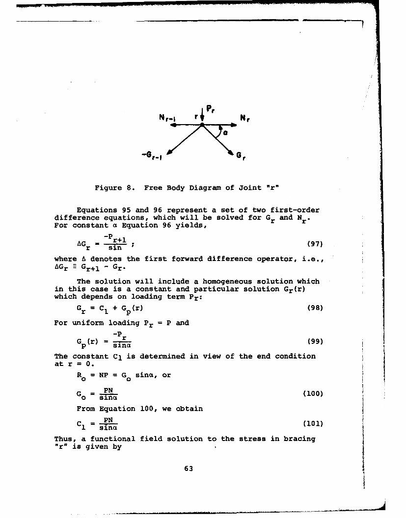
Nr-I Nr
Figure 8. Free Body Diagram of Joint "r"
Equations 95 and 96 represent a set of two first-orderdifference equations, which will be solved for Gr and NrFor constant a Equation 96 yields,
-Pr+lAG = - r ; (97)r sin
where & denotes the first forward difference operator, i.e.,AGr E Gr+l - Gr.
The solution will include a homogeneous solution whichin this case is a constant and particular solution Gr(r)which depends on loading term Pr:
Gr = CI + Gp (r) (98)
For uniform loading Pr = P and
-PG(r) r (99)
p sina
The constant C1 is determined in view of the end conditionat r =0.
R = NP = Go sina, orPN
Go = (100)sincx
From Equation 100, we obtain
PNC1 = silnc (101)
Thus, a functional field solution to the stress in bracing"r" is given by
63
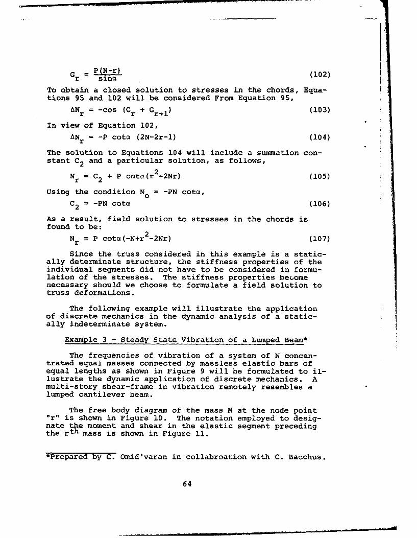
Gr = P(N-r) (102)
To obtain a closed solution to stresses in the chords, Equa-tions 95 and 102 will be considered From Equation 95,
AN = -cos (G + Gr+) (103)
In view of Equation 102,AN = -P cote (2N-2r-1) (104)r
The solution to Equations 104 will include a summation con-stant C2 and a particular solution, as follows,
Nr = C2 + P cota(r 2 -2Nr) (105)
Using the condition No = -PN cote,C2 = -PN cote (106)
As a result, field solution to stresses in the chords isfound to be:
N = P cotc(-N+r -2Nr) (107)r
Since the truss considered in this example is a static-ally determinate structure, the stiffness properties of theindividual segments did not have to be considered in formu-lation of the stresses. The stiffness properties becomenecessary should we choose to formulate a field solution totruss deformations.
The following example will illustrate the applicationof discrete mechanics in the dynamic analysis of a static-ally indeterminate system.
Example 3 - Steady State Vibration of a Lumped Beam*
The frequencies of vibration of a system of N concen-trated equal masses connected by massless elastic bars ofequal lengths as shown in Figure 9 will be formulated to il-lustrate the dynamic application of discrete mechanics. Amulti-story shear-frame in vibration remotely resembles alumped cantilever beam.
The free body diagram of the mass M at the node point"r" is shown in Figure 10. The notation employed to desig-nate the moment and shear in the elastic segment precedingthe rth mass is shown in Figure 11.
*Prepared by C. Omid'varan in collabroation with C. Bacchus.
64

0 ,M N
Figure 9. Lumped Mass Beam
d2 yr
rn dt 2
( tt)r+I
v: v,+,
Figure 10. The Free Body Diagram of Mass r
MMr(
(r -I1) Vr (r)
Figure 11. The Free Body Diagram of Panel r
65
The lateral displacement and rotation of mass r are denotedby Yr(t) and G.(t) respectively, and Yr(t) and Gr(t) arediscrete functions of r and continuous functions of t, thetime element.
Neglecting rotational inertia, the dynamic consideration
of mass r as shown in Figure 10 will require that:M'+ =0 (108)r r+l
d 2 y (t)r
V' - V. . .1 m 2 (109)r Vdt
The stiffness properties of elastic bars connecting themasses are given by:
Mr = k[40r_ + 20r - i (Yr-Yr l) (110)Mr k 4 r-l ~2 r L r r-1 10
M' = k[20 + 40 - (Yrr-i (111)Vr V' l r LMr'
= r= (Mr + Mr') (112)
where k -= EI/L.
Eliminate the joint rotations from Equations 110 and111 for a difference equation relating Mr, Mr, and Yr- Theresult may be introduced into Equation 108 to obtain:
6k(13(AV r+6)M; - f- AVrYr = 0 (113)
The difference operation AV (Debla), is an operatorconcerning typical three-node relations.
AVrYr -Yr-i - 2Yr + Yr+l (114)
AV r M M_ - 2Mr' + M'r+l (115)
Equation 113 represents a generalized three-moment equationfor non-zero displacement at the node points.
in view of Equation 108, Equation 112 will give,
Vr = Vr (M= M ) (116)
Introduce Equation 116 into Equation 109, to obtain,
d 2 YrAV M, + mL r = 0 (117)
r r dt 2
66

This is a second order difference-differential equation. Fora steady state harmonic motion with angular frequency w, wehave
2d r -W2 Y (118)r
dtrAs a result of Equation 118, Equation 117 can be transformedinto the following difference equation:
6rMM 2•Y = 0 (119)rr mw r r 0
The solution to a set of two difference equations as given byEquations 113 and 118 for Mk and Yr represents a closed func-tional solution to the problem. In a matrix form, these are
(Ar L rr] [(120)
A Vr -mLw 2[ a L.r, [0
For simple support conditions at r=0 and r=N, both M' and Ymust vanish at the boundaries.
The following finite series will satisfy the requiredend conditions naturally.
Nmr = i Ai sin- (121)
i=0N
NY = s 8i n (122)
i=0Introduce Equations 121 and 122 into Equation 120, we obtain
[2( 2+cosa~ -12 ki(cs - W rAi
2(cos8B 1) -mLw 2 jL 13
where
a= it (125)
For a non-trivial solution the determinate of coefficientsmust be identical with zero, and we obtain,
67
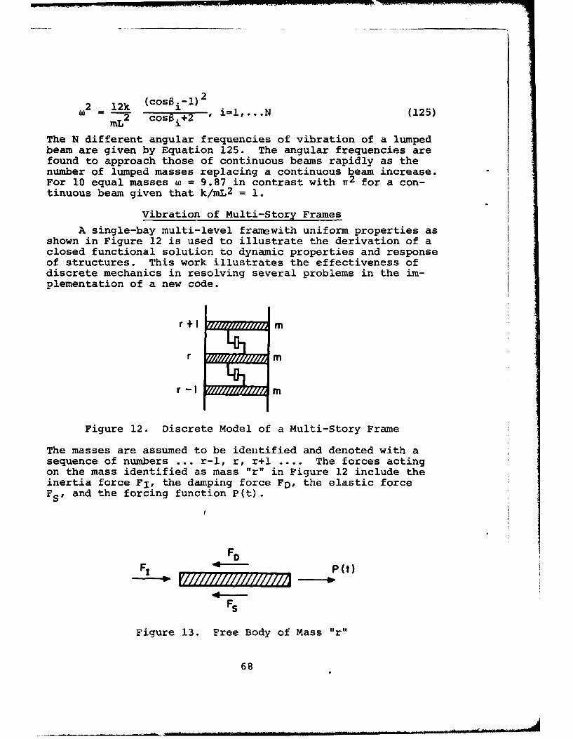
2 12k (cosi-l) 2
= M-T2 cos'S.i +2 , =1,. N (125)
The N different angular frequencies of vibration of a lumpedbeam are given by Equation 125. The angular frequencies arefound to approach those of continuous beams rapidly as thenumber of lumped masses replacing a continuous beam increase.For 10 equal masses w = 9.87 in contrast with w2 for a con-tinuous beam given that k/mL2 = 1.
Vibration of Multi-Story Frames
A single-bay multi-level framewith uniform properties asshown in Figure 12 is used to illustrate the derivation of aclosed functional solution to dynamic properties and responseof structures. This work illustrates the effectiveness ofdiscrete mechanics in resolving several problems in the im-plementation of a new code.
r+I m
r m
r-I m
Figure 12. Discrete Model of a Multi-Story Frame
The masses are assumed to be identified and denoted with asequence of numbers ... r-l, r, r+l .... The forces actingon the mass identified as mass "r" in Figure 12 include theinertia force F1 , the damping force FD, the elastic forceFS, and the forcing function P(t).
FOF, P(t)
FS
Figure 13. Free Body of Mass "r"
68
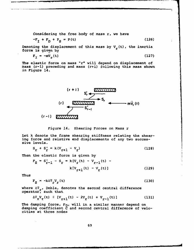
Considering the free body of mass r, we have-FI + FD + FS = P(t) (126)
Denoting the displacement of this mass by Vr (t), the inertiaforce is given by
FT = -mVr (t) (127)
The elastic force on mass "r" will depend on displacement ofmass (r-i) preceding and mass (r+l) following this mass shownin Figure 14.
(r +1 S, )V///7/'///771(r+I)
Cr) 4 - mV Ct)
(r -I )V7'// ,
Figure 14. Shearing Forces on Mass r
Let k denote the frame shearing stiffness relating the shear-ing force and relative end displacements of any two succes-sive levels.
Sr + S' = k(V 1 - Vr) (128)
Then the elastic force is given by
FS = Sr - S = k[V (t) - V (t) -S r-l r r r-l
k[Vr+l(t) - Vr(t)] (129)
ThusFS = -kAVrVr (t) (130)
where AVr, Debla, denotes the second central differenceoperator, such that
AV V (t) = [V (t) - 2V (t) + V r(t)] (131)r r r+1 r -
The damping force, FD, will in a similar manner depend ondamping coefficient C and second central difference of velo-cities at three nodes
69

F = -CAV Vr (t) (132)D r
Introducing Equations 127, 130, and 132 into Equation 126, weobtain:
mVr(t) - kAVrVr(t) - CAVr'r(t) = P(t) (133)
The second-order difference-differential equation as given byEquation 133 represents the mathematical model for the frameconsidered. It is a differential equation with respect tocontinuous element t, and a difference equation with respectto integer variable r.
First the steady state harmonic motion will be investi-gated. A solution will be given for an undamped structure(C = 0) subject to earthquake excitation (P(t) = 0). ThenEquation 133 will reduce to
mVr (t) - kAVrV r(t) = 0 (134)
In view of harmonic nature of structure in the absence ofdamping we may assume that,
V (t) = F sinwt (135)r r
where w denotes the angular frequency of vibration. Substi-tuting Equation 135 into Equation 134, we obtain,
2(AV -28)F = 0; 8 = 2 (136)
r r 2k
The solution to Equation 136 is found to be:
Fr = A sinyr + B cosyr, for (-2 < 8 < 0) (137)
Fr (_i)r [A1 coshnr + A2 sinhnr], for (0 < -2) (138)
where
y = cos (1+8), n = cosh (-1-8) (139)
The summation constants A, B, A, and A2 will first be de-termined. Then Equation 135 witl be used to express func-tional solution to displacement Vr (t). For the purpose ofillustration, the solution corresponding to (-2 < 8 < 0)only is presented herein.
For a steady-state vibration of a "N" story frame fixedat r = 0, the end conditions are assumed to be:
Vo(t) = 0 (140)
0 M 0 (141)
70

0 (t) 0 (142)
[Vr+ (t) - Vr(t)IrN = 0 (143)
Equation 143 implies that the shear at r = N vanishes. Equa-tion 140 will given B = 0. Then Equations 141 and 142 arealso satisfied. Equation 143 will give:
A[siny cosyN + (cosy-1) sinyN] = 0 (144)For a nontrivial solution (A yi 0) we must have
siny cosyN + (cosy-l) sinyN = 0 (145)
Equation 145 is a function of three parameters, N, k/M, andw, angular frequency. A computer program can be employed toplot w versus k/M for different choices of N. Such a graphi-cal solution is rationally based and reflects considerableimprovement over existing solutions to frame natural fre-quencies.
A functional solution to the shear force at differentiallevels of a multi-story frame due to a unit impulse accelera-tion at the base can also be formulated. The response due toany particular earthquake acceleration is the result of inte-gration of response due to unit impulse load.
The boundary conditions for a unit impulse acceleration
acting at the base of a multi-story frame are assumed to be:
Vr (0) = 0 (146)
0 (o) = 1 (147)
[Vr+l(t) - Vr(t)]r=N = 0 (148)
Equation 146 is naturally satisfied in view of Equation135. Equations 147 and 148 yield:
1B = - (149)
A = [siny sinyN - ý cosyN] (150)[siny cosyN - ý sinyN]w
Given summation constants A and B, a closed functionalsolution to displacement response Vr(t) is obtained, and wewill be in a position to formulate shear response spectrum.The shearing force Qr(t) is equal to the total sum of in-ertia forces acting on the masses above the rth level.
NQ(t) = - mW2V(t) (151)ri=r+l
71
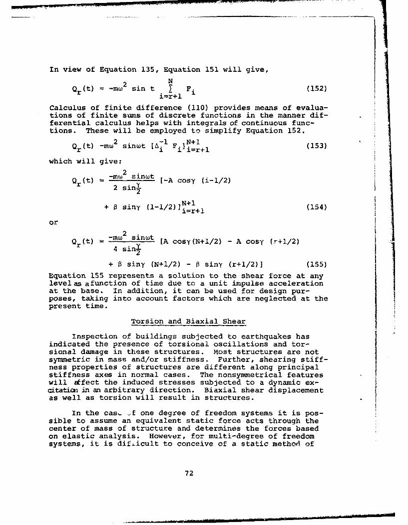
In view of Equation 135, Equation 151 will give,2 N
Qr (t) = -m2 sin t I F (152)i=r+l
Calculus of finite difference (110) provides means of evalua-tions of finite sums of discrete functions in the manner dif-ferential calculus helps with integrals of continuous func-tions. These will be employed to simplify Equation 152.
2 -l N+1
Qr(t) -mW2 sinwt [A-1 F.]I.+l (153)
which will give:
22 sinw
2.N+I+ 0 siny ( 1-1 / 2 )Ji=r+l (154)
or-mw 2 sinwt
Qr(t) 4 sinwt [A cosy(N+l/2) - A cosy (r+1/2)2 I
+ ý siny (N+1/2) - a siny (r+1/2)] (155)
Equation 155 represents a solution to the shear force at anylevel as afunction of time due to a unit impulse accelerationat the base. In addition, it can be used for design pur-poses, taking into account factors which are neglected at thepresent time.
Torsion and Biaxial Shear
Inspection of buildings subjected to earthquakes hasindicated the presence of torsional oscillations and tor-sional damage in these structures. Most structures are notsymmetric in mass and/or stiffness. Further, shearing stiff-ness properties of structures are different along principalstiffness axes in normal cases. The nonsymmetrical featureswill ifect the induced stresses subjected to a dynamic ex-citatin uin an arbitrary direction. Biaxial shear displacementas well as torsion will result in structures.
In the cas. _f one degree of freedom systems it is pos-sible to assume an equivalent static force acts through thecenter of mass of structure and determines the forces basedon elastic analysis. However, for multi-degree of freedomsystems, it is dif.ficult to conceive of a static method of
72
analysis and there is a dearth of rational solutions fortorsional oscillation of multi-story frames, and little isknown regarding combined torsion and biaxial shear behaviorof high rise structures. Consciousness of their importancehas, nevertheless, led to adoption of provisions in mostcodes and specifications. Housner and Outinen (67) haveinvestigated the dynamic behavior of single-story structuresin torsion. Bustamante and Rosenblueth (68) have made ageneral examination of code provisions and available litera-ture. Shiga (69) has presented a manner of formulation ofdynamic behavior of multi-story frames in torsion in caseswhen the centers of mass and rigidity coincide. However,the method is not easily applicable since it requires pre-determination of rigidity ratios in shear and torsion of eachlevel in relation to all other levels.
The presentation here illustrates a method of formula-tion of dynamic properties and response in torsion and bi-axial shear. The illustration assumes identical mass andgeometry for all levels.
The displacements of level "r" are designated by ur, vr,and Or- ur and vr denote displacement parallel with x and y,the principal elastic axis. Or denotes the angle of distor-tion and for convenience will be transformed into a parameterwr
wr = (156)R2 r
R = radius of gyration of mass m of each level.
z
Figure 15. Principal Elastic Axis
First influence coefficients will be defined for dis-placement and force interaction between any two successivelevels * will be used to designate the force in x direc-tion of anj one floor due to a unit displacement in y di-rection for a rotation corresponding to unit w of following
73
floor. kz will denote torque in z-direction for a rotationcorresponding to unit w of following panel.
kx = k reactive force directiony unit displacement direction
Given , the ratio of rigidity against shear in y directionto that in x direction; we have
ky = akx . (158)y x
In view of the choice of x and y as principal elastic axeseswe have
kx = k = 0 (159)y x
Equation 159 will serve as the basis for choice of principalaxes x and y. e, y, n, el, e 2 will'be used to designateother influence coefficient ratios as defined by the follow-ing relations:
kx =e k (160)kz
ky e 2 kz (161)
kz = x (162)
x xk ykx (163)
ky = qky (164)z y
In the absence of damping, inertia and elastic forcesin x, y and z, directions will be active. The inertia forcesare given by:
I= -mr (165)
I = -mir (166)
I =-MV, (167)z r
The shearing elastic forces acting on panel r are a functionof displacements of the mass preceding the mass succeedingthis panel. V the shearing force in x direction, is givenby Figure 16.
Vx = Sr S (168)r r-lI
In view of influence coefficients defined earlier, we find
74

Mil
AUr
- Sr
v I /1r-,
Figure 16'. Shearing Forces in x Direction
S= kX AU + k' AV + kx Aw (169)r x r.xr
Sr- =k VU + kx Vv + kx Vw (170)
Where A and V denote the first forward and backward dif-ference oterators
Au Ur+1 -ur Vu u -u U (171)r ~ rr r r-l(1)
Considering Equation 159, and introducing Equation 169and 170 into Equation 168, we obtain
Vx = k x [AV Ur + YAVw] (172)
The shearing force V in the y-direction is found in asimilar manner to be:
V = ckx [AVv + nAVwr (173)y x r r
The torque T is found to be:zT = akx [AVw + e 2 AVv + elAVur (174)
It will be assumed that the principal mass and elastic axesare parallel as shown in Figure 17.
Denoting the eccentricities between center of mass cand elastic center G by a1 and a2, consideration of the freebody diagram of mass r as shown in Figure 17 will requirethat:
75

vy
Yx 1z
VX G X1:
Figure 17. Principal Directions and Forces
I x + Vx = 0 (175)
Iy + Vy = 0 (176)
Iz +T +Vxa 2 -Va= (177)
where a, and a are positive as shown in Figure 16. In viewof Equations 165-167 and 172-174, we obtain
-ur + AVkx [u + w] 0 (178)r x r r
-Mvr + AVtkx [v + wr] = 0 (179)r x r r
-Miw + AV~kx [AIW + A2 Ur + A3 v] = 0 (180)
wherein,
M =-, A1 8+ a 2y - a1 n, A e2 =e e 2 ,
x
A3 =e 2 - aIa (181)
Equations 178-180 reprcesent a set of three difference-differential equations for Ur, Vr, and wr. The mathematicalmodel for torsion combined with biaxial shear of a shearframe is a second order differential equation with respectto time element and second order difference equation withrespect to displacement elements.
In view of the fact that damping is assumed to be ab-sent, we have,
76
Ur = Urq(t), vr =Vrq(t), wr = Wrq(t) (182)
where
q(t) = A coswt + B sinwt (183)
Considering Equations 182 and 183, we find
r = -W 2u r, r = -W 2v r, w = - 2 w r(184)r W r~ r W r1 r r 14
Equation 184 will serve to separate difference and differen-tial mathematical models. In view of Equation 184, Equations178-180 will give:[ ~2 u
(AV + MW 0 *AV
0 (cAV + MW2 ) an Z v = [0] (185)
[ A2 AV A3 AIAV+MW w
A solution to vector difference Equation 185 to meet physicalboundary conditions of multi-story frame is feasible by theaid of the stress Function approach. For fixed end condi-tions at r=0 and r=N, a solution is easily feasible and willbe given to conclude this illustration. Fixed end conditionscan be met naturally through assumption of the following fi-nite series representation for displacements:
u rA.N
Vr = • Bi sin bir, bk N (186)i=l 1N1(186)
w C.
Introduce Equation 183 into Equation 182, where we obtain thefollowing:
2 cosbi-2)+Mw2 0 2(cosb i- 1)
0 2a(cosbi-l)+MW2 2ctn(cosbi-l) 0=[
2A (cosbi-l) 2A3 (cosbi-l) 2A 1 (cosb- 1 l)+MW2
i=l,...,N) (187)
The N different frequencies of vibration of frame (i=lto N) in torsion and biaxial shear are contained in the solu-ticn to the linear equatian derived from the expansion of thedeterminate in Equation 187.
The strength of the technique in discrete mechanics il-lustrated in these examples will be more fully appreciated
77
_ Iii

considering the fact that torsional vibration of frameworksis recognized as one of the more complex problems in earth-quate engineering. Scarcity of literature regarding thesubject is an evidence of this point of view. This illus-tration has been concerned with more than torsional vibra-tion in formulating the case of torsion combined with bi-axial shear displacement.
78

APPENDIX B
STATISTICAL METHODS
General
There exist uncertainties in the prediction of the oc-currence of future earthquakes as well as the estimation ofthe resistance of structural materials. Therefore, it isdesirable to apply statistical methods to problems of earth-quake engineering.
The objective of this appendix is to review and summa-rize available literature in this regard. The terminologyof statistics is introduced in this section as well aswherever it is necessary. The statistical characteristicsof strong-motion earthquakes and their computer simulationsare then discussed. The random response of seismic struc-tures is reviewed. Finally, the general problem of struc-tural safety in earthquake engineering is described and dis-cussed, along with a brief introduction to decision anal-ysis.
Although the magnitude of an earthquake can be repre-sented with the use of the Richter scale and the intensitycan be described with the use of the Modified Mercalliscale, the most basic and useful data of earthquake engi-neering are the recordings of ground accelerations duringstrong-motion earthquakes (130). The record of an indi-vidual earthquake, say x(wl,t), can be considered as a sam-
ple function of a random process X(w1li), the definition of
which along with some other terminologies are introducedherein (131).
A random process (or stochastic process or randomfunction) is a family of random variables indexed by an ar-gument w in a sample space 0 and a parameter t in an indexset T, i.e., X(t) E{X(w ,t) : weQ, tET}. In earthquake
engineering applications, the parameter t denotes time.For a fixed value w in Q, say wl, X(wl,.) = X(wI) is a
function of t representing a possible observation of therandom process. The function X(wI) is called a realization
or a sample function of the process. For a fixed value oft, say tI, X(tl,') = X(tI) is a random variable, which is
79
a function on the sample space i such that a specific valueis assigned to each and every outr;ome w. The probabilitythat a random variable is less than or equal to a specificvalue x is called the distribution function, i.e.,
FX(t 1 ) (x) - P(X(t 1 ) < x) (188)
Equation 188 is called the first-order distribution of therandom process X(t) with its corresponding density functionas follows:
aFx (tI) (x)
PX(t 1 ) W= ax1 (189)
Given two times instances t1 and t 2 , there are two random
variables X(t 1 ) and X(t 2 ). The second-order distribution
and density functions are respectively as follows:
F (x )E P((t x1 (190)X(t1W(t 2 ) x1 x2 ) 1PXtI) X(t 2 ) < x 2 )
22PX(tl)X(t 2 ) (Xlx 2 ) - a 2 F (xlX 2 ) (191)
Mt 2 ax ax2 X(t WXt 2
The description of a random process can also be made bythe following moment functions:
•X(tl) = E[X(tl)] =-f x PX(t 1) (x) dx (192)
xx(tllt2) = E[X(tl)X(t 2 )]
-XX(tl)X(t 2 ) (xl,2 dxldx2 (193)
where the first moment p (tl) and second moment 0xx(tilt 2 )
are called the mean-value function and the autocorrelationfunction, respectively. The averaging operation, E, de-notes expectation. Another important second-order momentis the autocovariance function defined as follows:
Fxx(tlt 2 ) = E([X(t 1 ) - lX(tI)] [X(t 2 ) - Px(t 2 )])
S•xx(tl,t2) - PX(t') lx(t 2 ) (194)
If for a random process X(t), for all values of n,
80
PX (t) X (t 2) ... X (t n) (x1 'X2,' A. , xn)
- PX(t 1 +a) X(t 2 +a) ... X(t n+a) (Xl'x 2, ... , Xn)
(195)
the process is called completely stationary or strongly sta-tionary or stationary in the strict sense. If Equation 195is applicable for n=l and n=2, the process is said to beweakly stationary or stationary in the wide sense. Then theexpected value is a constant and the auto correlation is de-noted by RXX(T) which is a function of T = t 2 - tI. Al-though seismic ground motions are nonstationary, they aresometimes represented with stationary random processes forthe sake of simplicity, as it will be discussed later.
For a weakly stationary process X(t), a frequency de-
composition of the autocorrelation function RXX(T) can be
made as follows:
RXX([)= f G XX(w) exp(iwT) dw (196)
D XX(w) f RXX(T) exp(-iT) dT (197)
If X(t) is a real-valued process, (DX(w) is a non-negative
and even function of w. Equations 196 and 197 are usuallycalled the Wiener-Khintchine relations. Note that,
RXX(O) = f $XX(W) dw = E[X 2(t)] (198)
Equation 198 can be interpreted to mean that XX(w) de-
scribes the density of the total mean-square value over thefrequency domain. Therefore, the function XX(w) is called
mean-square spectral density. It is also called the power
spectrum because EX 2(t)] is often a measure of averageenergy.
Statistics of Strong-Motion Earthquakes
Housner (19) represented the earthquake as a series ofimpulses which are random in time. The ground accelerationX(t) is given by
81

X(t) = [ V. 6(t - jt - tj) (199)j J
where V. is a random variable representing the magnitude of
the jth impulse, t0 is an average period computed by divid-
ing the total time by the total number of pulses, jt 0 + t.
is the time elapsed between the beginning time and the ar-
rival of the jth pulse, and 6(t) is the unit impulse func-tion. The random variable V. is specified with given mean2E[V] and mean-square E[V 2]. Later, Thomson (20) showed thatthe power spectrum of a random process as given by Equation199 and with E(V] = 0 is as follows:
,(W) 1 T g(w)1 E[V2] (200)
where g(w) is the Fourier transform of the pulse shape.When the pulse duration is short in comparison to the periodof vibration, !g(M) approaches unity irrespective of thepulse shapes. Consequently, the power spectrum was foundto be proportional to the weighted sum of the mean-squarevalues, which is the same as the mean-square value of allthe pulses. In other words, the power spectrum in thiscase becomes a constant regardless of the pulse shape andtime spacing.
Goodman, Rosenblueth, and Newmark (61) used a velocitypulse model, in which the pulses are either uniformly orrandomly occurring in time. Later Rosenblueth (132), andRosenblueth and Bustamante (133) used an acceleration pro-cess which was generated from closely spaced velocity stepsof random sign and magnitude with a constant intensity perunit of time.
When the power spectrum of a random process is foundto be constant, the process is called "white noise" becausethe energy content of the process is considered to be uni-formly distributed over the entire frequency range. By-croft (21) proposed such a white noise with a constant
spectral density of 0.75 ft 2/sec 4cps and a duration of 30seconds for the representation of typical strong-motionearthquakes. The basis of comparison for this study is theresponse spectrum obtained by Housner (134). Ward (26)adopted a similar white noise process tor analog simula-tions with some consideration to emphasize power at certainfrequencies.
82

Because observations showed that certain frequenciespredominate the ground motion for given soil conditions,Kanai (135) obtained a response process of the soil over-burden to a white noise excitation at bedrock. Tajimi (136)suggested determining spectral density from spliced and re-peated sections of the actual earthquake records. Caugheyand Stumpf (137) used this type of model and found root-mean-square response to the 1940 El Centro earthquake.
Bogdanoff, Goldberg, and Bernard (22) studied the useof a nonstationary random process in representing earth-quake accelerations as follows:
nX(t) = I t a (exp[-a t]) cos( t + y t > 0 (201)
j=l
where aj, aj, and ai are given sets of positive numbers withJ
a1 < 82 < ... < an, and yj are n independent random vari-
ables uniformly distributed over an interval [0,2n]. Themean value is zero and its variance function has a shape asexpected from an earthquake record. Later, Goldberg, Bog-danoff, and Sharpe (23) used the same process except makingai also independent random variables, each uniformly dis-J
tributed over the interval [6,46]. This modification causeslittle effect in the appearance of sample functions, butthere seems to be considerable difference in their responsespectra.
Lin (24) proposed the use of a nonstationary randomprocess, which is obtained by passing a nonstationary shotnoise through a linear filter. The resulting process isalso called a filtered Poisson process (138,139). A shotnoise S(t) refers to a series of random pulses, the arrivalsof which are defined by a Poisson process N(t), i.e.,
N(t)S(t) = Y Xk " 6(t - Tk) (202)
k=l
where Yk are mutually independent random variables and 6(.)
denotes the unit impulse function. Furthermore,
E[S(t)] = 0 (203)
E[S(t i)S(tt2l = ittI6tt2 . til (204)
In addition to generating an earthquake-like process, thelinear filter can also be used in matching the frequencycontent of the process to that of recorded ground motions.
83

Because it is frequently difficult to obtain analyticalsolutions for structural problems in earthquake engineering,statistical answers can be obtained by the simulation ofthese problems with the use of digital or analog computers.Simulation techniques for earthquake motions as stationaryprocesses were developed by Housner and Jennings (25) usinga digital computer and by Ward (26) using an analog com-puter. Nonstationary earthquake motions have been simulatedwith the use of digital computers by Shinozuka and Sato(29), Amin and Ang (27), Jennings, Housner and Tsai (28),
Hou (32), Rascon and Cornell (30), Iyengar and Iyengar (33),and Levy (31). As it is summarized by Levy (31), the typi-cal operation of the digital simulation is (a) to generatean equally spaced time sequence of uncorrelated random num-bers by drawing numbers following a normal distribution withzero mean, (b) to multiply these numbers by a time-dependentmultiplier, and (c) to filter these numbers with a given im-pulse response function to obtain the sample function of theearthquake-like acceleration.
In earthquake engineering, passive analog computershave been used by various investigators including Alford,Housner and Martel (140), Naka,Kato, and Yuasa (141), andMurphy, Bycroft, and Harrison (142). Bycroft (21) used anactive analog system with amplifiers in studying the re-sponse of linear as well as elasto-plastic single-degree-of-freedom systems to white noise excitation. Other inves-tigators using the analog computer in earthquake simulationsinclude Merchant and Hudson (143), Cherry and Brady (144),Brady '145), Ward (26), and Wirsching and Yao (146). Acomprehensive treatment of random-process simulation ingeneral can be found in Korn (147).
Random Response of Seismic Structures
Until approximately 10 years ago, the principal appli-:ations of random vibration studies have been to missiles,;atellites, and other space vehicles. Recently, the ran-lom vibration of seismic structures has been emphasized.irrespective of the type of structures studied, the ulti-tate objective of the study of random vibration is to en-ure the maximum reliability of the structure. Some as-ects of structural reliability will be discussed in theext section. In this section, the fundamentals of randomibration will be reviewed along with its application inarthquake engineering.
When the excitation can be represented by a randomrocess, the problem of computing certain statistics of the
84

response belongs to the study of random vibration. Duringthe past decade, many text or reference books concerningthis subject area have been published (131, 148-153).
A linear system can be characterized by its response to(a) the sinusoidal forcing function, and (b) the impulsiveforcing function. As an example, consider a mechanical sys-tem with the following equation of motion:
x + 2Cw + +2X - m (205)
where
2 k•o =m-
c
0
m = mass
x = displacement
c = damping constant
k= spring constant, and
f(t) = forcing function.
When the forcing function is sinusoidal, i.e.,f (t) = Aeil;.t,
let the particular solution be
x (t) = Kelit (206)p
Substituting Equation 206 into 205, we obtain,
K m A = A = AH(w) (207)MW2 _w2 +2wW) ZTW)
0 owhere Z(M) is called the "mechanical impedance" of the sys-tem, and H(w) is called the "frequency response function"or the "transfer function" of the system.
When the forcing function is impulsive, i.e.,
f(t) = C 6(t),
the particular solution becomes,
85

x (t) = C h(t) = C exp(-+i )t],C 2 wom: ,
0i
for t > O0 (208)The function h(t) in Equation 208 is called the "impulse re-
i sponse function. "
It is to be noted here that the response of a stablelinear system to an arbitrary excitation does not depend agreat deal on the initial conditions after a fairly longtime. This is known as the steady-ýstatp condition, duringwhich the following relations exist with the use of theprinciple of superposition:
x (t) = f H(w) 1(w) exp(iwt) d
t= f f(T) h(t - T) d' (209)
0
where
f(w) = f f f(t) exp(iwt)dt, and (21010
f(t) = Y M(w) exp(iwt)dw = f fl(T)h(t - T)dT (211)-00 0
tThe integral f f(T)h(t-T)dT is called the "Duhamel inte-
0
gral." From Equation 209, the following convolution theo-rem of Fourier transformation can be obtained:
h(u) = - f H(w) exp(iwu)dw, (212)-CO
and
HIM) = f h(t) exp(-iwt)dt (213)-Go
When the excitation is represented by: a random processF(t), the response also becomes a random process X(t).Correspondingly, Equation 205 becomes
86

xt+2 k(t) + X2 X(t) F(t) (214)0 0 m
assuming that (a) the derivatives of X(t) exist in mean-square sense (131) and (b) the random excitation begins att = 0.
Because the principle of superposition holds for alinear system, we have
tX(t) = J F(T) h(t - T)dT (215)
0
Also because integration is a linear operator, we obtain,
tE[X(t)] = f E[F(t)] h(t - T))dT (216)
0
and tIt2
Oxx(tl't2) = f FF(TIT2)h(tI-fl)h(t2-T2)d IdT 20 0
(217)
If F(t) is stationary in the wide sense, i.e.,
ElF(t)] = U F = constant (218)
and
E[F(t)F(t + T)] = RFF(T) (219)
it can be shown that
E[X(t)] = PX = constant (220)
andE[X(t)X(t + T)] = RXX() (221)
-Equations 220 and 221 indicate that the response of a linearsystem to weakly stationary excitations is also weakly sta-tionary. Furthermore, the spectral density of the responseprocess is equal to the product of the spectral density ofthe forcing process and the "transmittancy function" or the
"system function" IH(w)1 2 , i.e.,
XP () = IH(w) 12 %FF(W) (222)
For the given system subjected to a white noise excitationwith *FF () = Wo, the mean-square response is found to be
87
as follows:S'TW
IX 2(t) = R (o) = Wo I H (w) 12d = (223)-0 2tc 00m
More advanced topics in random vibration are summarized anddiscussed by Lin (131).
Rosenblueth and Bustamante (133) found a distributionfunction for the structural response to an idealized earth-quake excitation, which was represented by a series of im-pulses random in time. Bogdanoff, Goldberg, and Schiff(154) studied the effect of ground transmission time on theresponse of long structures. Shinozuka, Hakuno, and Ita-gaki (155) evaluated the response of a multi-story framestructure to nonstationary random excitation. A general dy-namic analysis for both stationary and nonstationary re-sponse of linear structures was proposed by Shinozuka andYang (156). A numerical method for the analysis of complexstructures subjected to nonstationary random excitation wasalso made available by Yang and Shinozuka (157). Recently,the evolutionary power of random processes and its applica-tion to earthquake engineering was presented by Shinozuka(158) and Brant and Shinozuka (159). The application ofrandom vibration theory to earthquake engineering problemswas also contributed by Bogdanoff, Goldberg, et al. (22,23)and Penzien and Liu (17). Moreover, the problem of randomvibration of nonlinear systems has been studied by many in-vestigators (160-167).
Structural Safety in Earthquake Engineering
The basic problem of structural safety can be describedin the following manner. Consider a structural component.Usually, the resistance is considered as a function of theapplied force, and failure is assumed to occur whenever theforce, S(t), exceeds the resistance R(t). In general, bothforce and resistance are random in nature. Therefore, the"life" of this structural component can be represented byrandom variable T. The reliability function of this struc-tural component, LT(t), is defined as the probability of
the event that its useful life will be at least t, i.e.,
LT(t) = P(T > t)
= P(R(T) > S(T), 0 < T < t) (224)
Because of wear, cumulative damage, and increasing chance ofencountering larger loads with increasing time, the relia-
88

bility of a structure is usually a monotonically decreasingfunction.
By definition, the distribution function for the life,T is then,
FT(t) = P(T < t) = 1 - LT(t) (225)
For a special case where R(t) = r = constant, and S(t) is aknown random function, the problem of finding FT(t) belongs
to the "first passage" (or "barrier" or "crossing") problem,which will be discussed later. Another special case is thatwhen R(t) = R, S(t) = S, both R and S are random variableswith known distributions. Freudenthal first proposed thebasic concepts of structural safety more than twenty yearsago (104). Later, Asplund (168), Brown (169), and Freuden-thal and Shinozuka (170) derived the expression for theprobability of failure. Shinozuka (171) then found theprobability of survival under n applications of load. Acomprehensive review of the classical studies of structuralreliability was made by Freudenthal, Garrelts, and Shinozukain 1964 (105). In 1967, Cornell (172) gave reliabilitybounds for cases where the loads and the resistance are notstatistically independent. Amin and Ang (173) establisheda monotonic property of the hazard function of structures,which is subjected to a sequence of random loads. Recentstudies of structural reliability include the use of an un-certainty factor (106,107), redundant systems (174,175),statically indeterminate structures (176,177), and plasticcollapse of structural frames (178).
In addition to its use as a common basis for comparingthe relative safety among alternative designs, the proba-bility of failure can be used as a constraint in the opti-mum design of structures. Hilton and Feign (179) used aLagrange multiplier technique to find the minimum weight ofa simple structure with statistically distributed force andresistance. This optimization technique was later refinedby Kalaba (180). In 1964, the simplex linear programmingmethod was used to solve the optimization problem followingthe development of a linear relationship between the weightand the probability of failure (181). Then Moses andKinser (182) developed computational techniques for the de-termination of failure probabilities of elastic frames andtrusses under multiple loading conditions, which were usedin the optimum structural design. More recently, the ef-fect of proof-load testing to reliability-based structuraloptimization was studied by Shinozuka, et al. (183,184).
In earthquake engineering, structural failures can re-
89
sult from excessive deformation, dynamic instability, or fa-tigue damage. Collapse of yielding structures during earth-quakes was studied by Jennings and Husid (185). The failureprobability of seismic structures was treated as a barrierproblem by Shinozuka, et al. (155, 186-193) and others (22,23,194,195).
The deterministic problem of dynamic stability has beenstudied by many investigators (196-202). When the axial ex-citation of the column is represented by a stationary Gauss-ian process, various stability conditions were obtained byAriaratnam (203), Kozin (204), and Caughey and Gray (205).Later, Caughey and Dickerson (206) studied the stability ofsystems subjected to a narrow-band random excitation. Re-sults from a recent study showed that, for a concentricallyloaded column without sidesway, dynamic instability due tothe vertical component of the earthquake excitation is notlikely to be a problem (207). However, significant lateralmotion of the structure occurs and thus may cause the col-umns to become unstable during an actual earthquake.
To improve the design of earthquake-resistant struc-tures, it is desirable to know more about the failure mech-anisms of these structures. Although it is possible to havelow-cycle fatigue failure in seismic structures (18,208),such effects have not been studied statistically. To date,the studies of random fatigue consist of cases with station-ary loading processes, which were summarized recently byTang and Yao (102). Miles (209) was the first to computethe mean value of cumulative fatigue damage for a narrow-band random process. An approximation was suggested byPowell (210) for the case where the stress did not follow anarrow-band process. The variance of the cumulative damageresulting from narrow-band random stresses were computed byCrandall, Mark and Khabbaz (211), Bendat (212), and Shino-zuka (213). Parzen (214) and Freudenthal and Shinozuka(215) applied the renewal theory to the study of random fa-tigue. Sweet and Kozin (216) incorporated physical proper-ties into the renewal model, which was compared to experi-mental results. Rice (217) developed an approximate densityfunction of the rise and fall statistics, which was used forthe prediction of fatigue crack propagation by Rice, Beer,and Paris (218). A comprehensive review of experimentalstudies in the field of random fatigue was made by Swanson(219).
Decision Analysis in Earthquake Engineering
In engineering problems, the engineer must decide on
90
the action to take among a space of possible acts A = {a}.Also, it is usually assumed that there exists a space ofpossible "states of nature (the way things really are)"0 = {W}. In order to obtain information about the state ofnature, engineers can conduct certain experiments from afamily of possible experiments E = {e}. The family of ex-periments E is said to include the "dummy" experiment whichrefers to a decision-making without experimentation. Thecollection of all possible outcomes for various experimentsis denoted by Q {= }. For each combination (a,O,e,w)sAXOXEXQ, it is assumed that the engineer can assign a con-sequence cEC.
As an example, the action to be decided upon might bewhether to accept or reject a lot of reinforcing steel bars.The possible states of nature might be (a) that all barsmeet the specifications, (b) that majority meet the speci-fication, (c) that only few bars meet the specification,and (d) none meets the specification. To obtain some in-formation concerning the state of nature, the engineer canperform certain experiments on a selected number of thesebars. The result of these experiments can be either satis-factory or unsatisfactory. For each possible combinationof (a,8,e,w), the consequence can range from excessivecost to defective structure as an end product. The deci-sion analysis can be used to guide a decision maker suchas the engineer in his choosing an action under uncer-tainty.
A comprehensive introduction to decision analysis witha minimum of mathematical demands is given by H. Raiffa(220). Other introductory references include G. Hadley(221), H. Raiffa and R. Schlaifer (222), Tribus (99), andH. Chernoff and L. E. Moses (223). Recently, many appli-cations of the decision theory to structural engineeringhave been proposed by several authors (108,109, 224-228).Also, the application of decision analysis and probabil-istic concepts to design codes was explored by several in-vestigators (229-232).
In 1763, Reverend Thomas Bayes suggested the use ofBayes' Theorem in combining the probability based onhunches with that based on relative frequencies. Gener-ally, the Bayesian, or subjective, approach to probabil-istic methods incorporates or introduces intuitive judge-ments and feelings into the formal analysis of a decisionproblem. The resulting choice of an action is said to beconsistent with the decision maker's preference for vari-ous consequences as well as his judgement about the un-certainties involved in the problem.
91

To begin the decision analysis, it is desirable to con-struct a "decision-flow diagram" or "tree." The engineerhas a choice at the very beginning: to be involved or not tobe involved (e.g., he can quit the job in case he choosesnot to be involved). If he decides to be involved in thedecision-making process, he must decide then whether to ob-tain more information through experimentation (e 0 ,e 1 ,...).
For each of these experiments, there are possible outcomes(W1,2,... ), which depend on chance. At this point, the en-
gineer can choose to take the actions (al,a 2 ,...). Then, by
chance, the state of nature may be (61,02,...). A typicaldecision flow diagram is given in Figure 18. FollowingRaiffa (220), a "decision fork" is denoted by a small squareand a "chance fork" by a small circle. Note that thereexists a "consequence" c for each possible "path" in thetree.
At each chance fork, it is important to know the prob-ability that any one of the alternative branches will betaken by chance. In other words, we need to know the prob-abilities of experimental results, i.e., P(wi), and the con-
ditional probabilities of states of nature given that agiven experimental outcome has occurred, i.e., P(6i iWi).To compute these probabilities P(ei w1i), (from quantities
P(0.), P(WijO.), the following Bayes' Theorem can be used.
P(wil e_)P(e.)P(e Ji) = Pi y)le (226)
CI(ep92 (e1 ,w - C1W 0
000
uTO BE -- (0)
INVOLVED
Figure 18. Typical Decision-Flow Diagram
92

For quantitatively representing consequences, it isfirst necessary to define a preference relation " " over theset of consequences C = c such that (a) if ci,CccC, theneither cipcj, c ci, or both and (b) if cifcj, and cjfck#
then c ick. The decision maker can then express his pref-erence for consequences by a real-valued "utility function"u(°) such that
ciEcj if and only if u(ci) > u(c.)
The choice of experiment e* and action a* should be madesuch that
E ,Iu(e*,w,a*,8)] = max E0 [u(e,w,a,O8) (aeA (227)eeE
93
APPENDIX C
SEISMIC BEHAVIOR OF CONCRETE AND METAL STRUCTURES
General
The behavior of steel, reinforced concrete, prestressedconcrete, and composite structures has been tested by therecent strong motion earthquakes of Skopje, Yugoslavia, in1963; Niigata, Japan, in 1964; Alaska, U.S.A., in 1964; andCaracas, Venezuela, in 1967. Especially the earthquakes ofAlaska and Caracas have revealed valuable information re-garding the behavior of different materials as well as theoverall behavior of multistory buildings. Recently it hasbeen customary for teams of structural engineeers to go tothe site of an earthquake immediately after its occurrenceand to study the various forms of failure and behavior ofdifferent materials. The reports of these engineers aretherefore very useful for locating areas of further re-search.
First of all, these damage reports of the four afore-mentioned earthquakes are examined to help locate the prob-lem areas. Then the research which has been done concern-ing these problem areas will be cited and discussed.
Damage Reports from Niigata Earthquake
1. Steel Building Structures (Minou Makina, Building Re-search Institute) (233)
Most of the steel structures in the city took theearthquake quite well. Where there were fissures and de-pressions and if the subsoil conditions were bad there wasconsiderable damage; this was the case for the NiigataTimber Manufacturing Center. There were occasional failuresat beam-column connections (Plywood Factory in Niigata,Pipeline Station for Petroleum Gas in Tsukiji Village),gusset plates (Agricultural Warehouse of Niigata EconomicUnion in Niigata), and fracture of tensile members (a fac-tory building in Nikaho Town). None of these buildings wasmultistory and poorness of subsoil conditions was shown tobe the primary reason for most failures. A boiler house inNiigata which is a steel gabled frame house (35 m. high)and which sits on a mat foundation with 8 m. concrete pileswas structurally undamaged even in a destructive area ofsubsoil.
2. R/C Constructions (Koichiro Ogura, Meiji University)(234)
Out of a total number of 340 normal reinforced concrete
94
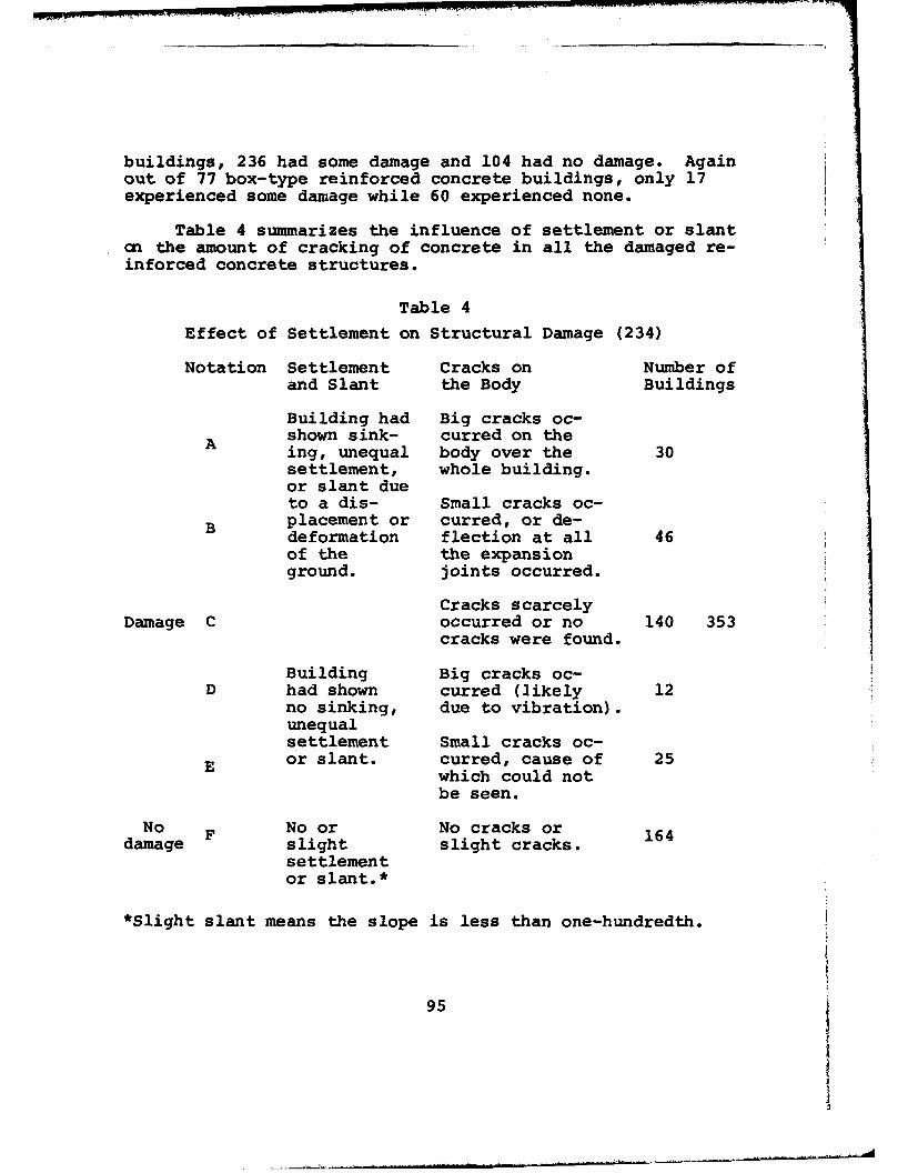
buildings, 236 had some damage and 104 had no damage. Againout of 77 box-type reinforced concrete buildings, only 17experienced some damage while 60 experienced none.
Table 4 summarizes the influence of settlement or slantan the amount of cracking of concrete in all the damaged re-inforced concrete structures.
Table 4Effect of Settlement on Structural Damage (234)
Notation Settlement Cracks on Number ofand Slant the Body Buildings
Building had Big cracks oc-shown sink- curred on theA ing, unequal body over the 30settlement, whole building.or slant dueto a dis- Small cracks oc-
B placement or curred, or de-deformation flection at all 46of the the expansionground. joints occurred.
Cracks scarcelyDamage C occurred or no 140 353
cracks were found.
Building Big cracks oc-D had shown curred (likely 12
no sinking, due to vibration).unequalsettlement Small cracks oc-
E or slant. curred, cause of 25which could notbe seen.
No F No or No cracks or 164damage slight slight cracks.
settlementor slant.*
*Slight slant means the slope is less than one-hundredth.
95

3. Reinforced Concrete Structures, Syuzo Takada (ChibaUniversity) (235)
From Table 4 the following information is obtained.Nine such (reinforced concrete) buildings were observed andfour different modes of failure were considered: (a) damageto body, (b) damage to finish, (c) overturning, and (d) un-equal sinking. These buildings are of moderate height (6-11stories) and none of them experienced any "damage to body."Only one was observed to have "damage to finish." However,three of them experienced both "overturning" and "unequalsinking" (same three).
4. Building Damage and Soil Condition, Yorihito Ohsaki(Building Research I~istitute) (236)
After a big fire in 1955 in Niigata City, reinforcedconcrete construction expanded greatly and at the time ofthe 1964 earthquake there were a total of 1,530 reinforcedconcrete structures. Of these, 340 were more or less dam-aged by the earthquake. The following is an excerpt fromthe report of Y. Ohsaki:
"In every case of earthquakes in the past, woodenbuildings used to suffer heavy damage and reinforced con-crete structures remained safe. However, during the earth-quake of Niigata last year, the situation was completelyreversed, a fact which may be regarded as the most charac-terstic featrre of this earthquake. Considering this situ-ation, it seL.ns appropriate to focus attention mainly uponthe damage to reinforced concrete buildings."
The Venezuela Earthquake of 1967(Magnitude 6.5 on Richter Scale)
Reinforced concrete construction is by far the mostwidespread type of construction in Venezuela. In the LosPalos Grandes district where four buildings collapsed, allthe multistory construction is reinforced concrete with theexception of the two 30-story steel frame towers of theSimon Bolivar Center. Therefore the discussion will be fo-cused on the performance of reinforced concrete structuresin Caracas during the 1967 earthquake.
The concrete used in construction was of very goodquality and varies in strength from 2400 psi to 4300 psi.The ordinary reinforcing steel has a minimum yield strengthof 34000 psi which corresponds to a working strength ofabout 17000 psi. A type of high strength reinforcing steel(Heliacero) which is commonly used has a minimum yieldstrength of 56000 psi and a working strength of about 28000psi. This higher strength is obtained by cold working the
96

steel and alters the stress-strain diagram by eliminatingthe flat plateau between the yield point and the start ofthe strain hardening region.
The typical construction of multistory buildings inCaracas consists of reinforced concrete frames with hollowtiles as fillers. Most o9 the design practices would alsccorrespond to the provisions of the U.S. building codes.One exception may be the absence of top reinforcing in thecenter of joists and slab steel parallel to the joist.This would be considered as normal in areas where the seis-mic risk is very small but not in relatively severe seismicareas such as California in the United States. One majorproblem which was completely overlooked in design was theinteraction of the reinforced concrete frame with the fillerwall.
Of the 157 multistory (from 4-22 stories, most between10-20 stories) buildings in Los Palos Grandes district ofCaracas, Venezuela, four of them (10-12 stories) completelycollasped, 31 suffered major and 15 suffered minor damages(after subjective evaluation of Hanson and Degenkolb).
The absence of the top reinforcing steel in the joi.tsmay have been the reason for the failure of three of thecollapsed buildings. This, coupled with deviations fromoriginal plans and calculations led to the collapse offour buildings.
Causes for major structural damage can be classifiedin three groups. The first one is due to the unfavorableinteraction between the reinforced concrete frame and thefiller hollow tile. This localized the damage to the "soft"stories where no filler was used (especially first storieswhich were used for parking). However, the frames in these"soft" stories were not designed to carry the larger forcesand therefore failed. The second type of failure was dueto the unexpectedly high overturning moments. These momentscaused compression failures in the columns and in some casesruptured the less ductile Heliacero reinforcing steel intension. Last, but not least, is the failure due to poordetailing of connections. This is one area which is veryimportant and common to both reinforced concrete and steelstructures in earthquake resistant design.
The above discussion was based on a report by Hansonand Degenkolb for the American Iron and Steel Institute(237). The PCA report (238) also finds the Caracas codesand design procedures comparable to U.S. practices for a-seismic design. It is concluded that "...most of the dis-
97

tress resulted not from inadequate codes, but from a lack ofunderstanding of the dynamic behavior of structures."
Some statistics are given about the number of "unsafe"and collapsed buildings. "Out of 7000 buildings higher thanfour stories, approximately 180 buildings were damaged andlisted as temporarily unsafe. Of these 180, approximately40 had structural distress. Five out of the 1000 buildingshigher than 10 stories collapsed."
As the AISI report also points out, most of the high-rise buildings in Caracas were reinforced concrete con-struction. One of the interesting and plausible reasons offailure of these reinforced concrete frame buildings is dis-cussed in the PCA report. "High-rise buildings in Caracasare typically reinfcrced concrete frame construction with-out shear walls. Although the buildings were designed asframes, the interior partitions and exterior walls are con-structed with brittle clay tile of low strength but highrigidity. These walls give the buildings the stiffness andresponse of shear wall buildings and influenced the distri-bution of earthquake forces within the structure."
This adverse effect of frame-partition interaction wasalso pointed out in the AISI report and shows how differentstructures can behave under dynamic loading.
Skopje Earthquake of 1963 (239)According to the data gathered by the Statistical In-
stitute of the Socialist Republic of Macedonia the damage
inflicted upon the housing due to the earthquake can besummarized in Table 5:
Table 5
Earthquake Damages in Skopje (239)
Degree of Damage Flats Living Space PopulationDamaged Affected Affected
(M) (M) (M)Collapsed 8.5 7.05 8.5
Heavily damaged (most build-ings have to be demolished) 33.6 29.9 36.4
Moderately damaged 36.3 39.9 30.6
Slightly damaged 19.0 19.8 20.3Undamaged 2.6 3.4 4.2
98

Ambraseys (240) divided the buildings in Skopje intofour categories: (a) old adobe construction with or withouttimber bracing; (b) load-bearing brick wall constructionsupporting reinforced concrete, or wood floors supportedpartly by masonry walls and partly by reinforced concretecolumns and beams; (c) reinforced concrete skeleton build-ings with and without concrete shear walls; (d) therewas also one roof structure of prestressed concrete and afew isolated cases where use of prefabricated, prestressedor ordinary elements were made.
The new steel mill in the outskirts of Skopje was theonly steel frame construction.
The adobe and the mixed construction performed badlyas expected. The reinforced concrete skeleton buildingswere far better and only two collapsed. The taller build-ings (up to 15 stories) in this category perfurmed muchbetter since they were designed for wind forces. The pre-stressed construction totally collapsed when the supportingcolumns failed. The steel mill which was still under con-struction had only minor damage. None of the buildings wasdesigned for earthquake forces.
Alaskan Earthquake of March 27, 1964 (241)The damage caused during this earthquake is of special
importance because the many buildings affected by the earth-quake were designed according to the earthquake provisionsof the Uniform Building Code. The damage was caused eitherby the seismic sea wave (tsunami) effects, or by earth vi-bration effects. Most of the buildings of structural inter-est were in the Anchorage area, which experienced primarilythe earth vibration effects and therefore this aspect willbe considered here. Another big cause of damage was thelandslides which took place because of the earthquake; a de-tailed study of the soil conditions leading to these land-slides can be found in the report made by the Shannon andWilson firm (242). This earthquake also demonstrated thecorrelation between the epicentral distance to the struc-tures mostly affected by the earthquake. The epicenter ofthe Alaskan earthquake was about 75 miles from Anchorageand therefore the dominant periods were quite long (morethan 0.5 sec.). For this reason, taller and more flexiblestructures attracted more force, and this fact should bekept in mind when the damage reports are studied. The fol-lowing is a description of the damage on the metal and con-crete structures as quoted by Steinbrugge (241).
99

"All metal buildings performed excellently as may betypified by the usual absence of damage to all steel gasolineservice stations.
"Some damage, however, was noted in all metal structureshaving large elevated masses. Equipment shifted, one binfell, X-bracing broke, metal skin buckled, and steel columnstwisted at the Chugach steam power generating plant locatedin the Ship Creek section of Anchorage; differential settle-ments indicated that foundation problems probably accentuatedthis damage. Nearby, the Elmendorf Air Force Base had itsprincipal damage restricted to the steel connections from alarge elevated pit to the main structure. Overall damage toboth power plants was estimated to be slight, and overallequipment damage probably could also be classified as beingslight. A third power plant, owned by the City of Anchorageand also located in the Ship Creek area, had apparently neg-ligible damage.
"Hollow concrete block was a common construction mater-ial for small mercantile structures as well as for industri-al structures. Roof and supported floors were usually wood.When small in area, when one story high and when not locatedin the land movement areas, such damage as sometimes occurr-ed was usually no more than slight to moderate. Some para-pets fell, unanchored roofs punched out sections of thehollow concrete block walls, but collapse was uncommon.Wire webbing for reinforcement was usually laid in selectedhorizontal joints of the hollow concrete block. The place-ment of vertical steel was inconsistent. This reinforcement,in general, appeared to be of a size and amount that wouldnot be considered to be fully adequate in other sections ofthe United States which are considered seismically very ac-tive. Workmanship was often poor where collapsed wallswere noted; the concrete grout did not fill all of the cellsin many observed instances.
"Poured-in-place reinforced concrete wall constructionperformed well for small buildings. Usually the roof andsupported floor materials were wood for the small buildings,although not always. Instances of metal deck and metalopen web joist roof and floor systems were found. The per-formance of these structures was generally good and somewhatbetter than similar size structures of different masonrymaterials when not located in the land movement areas."
The five-story Penney Building which was entirely ofreinforced concrete (both poured-in-place and precast)collapsed. Poor detailing especially of the poured-in-placeto precast connections was a major cause for the collapse.
100
Also, large torsional forces were developed in the upperstories because second floor and above was structurally aU-shaped building.
The Four Seasons Apartment Building was six stories andwas only structurally completed (it had not yet been finish-ed). It had prestressed concrete (in both directions) slabsfor floors which were supported by steel columns. It alsohad two cores of poured-in-place reinforced concrete. Thesetwo cores failed and the building collapsed. Faulty splic-ing and shear connections, and the lack of grouting of theprestressing cables, were pointed out to be the major causesof failure. The building was very closely located to themain graben of the "L" Street landslide.
Hill Building which was eight stories had a centralcore of poured-in-place reinforced concrete, a steel frame,and at the upper stories poured-in-place reinforced concreteone-way slabs. The major damage was concentrated at thecentral core. Laboratory tests for the concrete indicatedexcessive organic material which had resulted in extremelylow strength concrete.
Steinbrugge (241) completes his report with the follow-ing conclusion: "Precast reinforced concrete performedrather poorly in too many instances. However, failures werealmost inevitably associated with the connections to the pre-cast elements. It would appear obvious that the materialwas usually not at fault, rather a lack of sound engineeringjudgment was the principal cause. There was no evidence toindicate that one construction material was superior to an-other when given comparable design and construction atten-tion.
After presenting these damage reports of the four earth-quakes, we shall now turn to the research done in the areasof steel, reinforced concrete, prestressed concrete, andcomposite structures under strong motion earthquakes. Acomparison of the performance of different materials is un-warranted. Steinbrugge's quotation in the last paragraphquite accurately sums up the situation. However, one pointshould be made regarding concrete structures. Concrete isa newcomer to the field of earthquake engineering. "Ductileconcrete" is a very recent concept (50). Therefore themajority of the literature concerns reinforced or prestress-ed concrete behavior under earthquake loading.
One of the biggest problems common to both steel andconcrete structures concerns detailing. Beam-to-columnjoints are one of the major problem areas. The following
101]
will comprise a detailed discussion of connections, both con-crete and steel, and also a representative paper will be pre-sented for each material emphasizing both the merits and theshortcomings. Other research will be cited briefly.
Reinforced Concrete
Splicing is one of the important details of beam-columnconnections. At the University of Illinois a series of tentests were carried out on lapped splices in beam-columnconnections (243). The main objective was to study the ef-fects of splice length, splice location, and stirrup spacingon the behavior of tension splices in column specimens. Thefollowing is an excerpt from the conclusions of the investi-gators (243):
"1. For equal splice lengths, splicing away from thepoint of maximum moment increases both the ultimate deflec-tion and the steel stress at ultimate.
"2. Placing the through bar on the inside of the crosssection resulted in a lower load and deflection at ultimate.
"3. A closer spacing of stirrups over the splice lengthresulted in greater ductility and also larger maximum steelstresses for the same concrete stress.
"4. The ultimate deflection of all the spliced speci-mens, except C-10, was less than half that of a similar un-spliced column."
Another valuable study of reinforced concrete beam-column joints was carried out by Hanson and Connor (244).This study specifically concerned the seismic resistance ofthe joints. The authors take the recommendations of Blume,Newmark, and Corning (50) as a basis for their investigationsand summarize them as follows:
"Crucial recommendations for earthquake resistant de-sign are the following:
"l. Sufficient transverse and shear reinforcement toprovide a shear strength greater than the flexural strength.
"2. Limitations on the amount of tensile reinforcementor required use of compression reinforcement, to ensureductility and energy absorbing capacity.
"3. Confinement of the concrete by hoops or spirals ofcritical sections such as beam column connections, to in-crease the ductility of columns under combined axial loadand bending.
"4. Special attention to details, such as splices inreinforcement and exclusion of planes of weakness that would
102
result from bending or terminating all bars at the same sec-tions."
With these recommendations in mind, the investigatorsdevised a test to determine joint reinforcement required toensure maintaining ultimate capacity for cast-in-place beamsand columns subjected to multiple reversals of loading ofmajor earthquake magnitude. An exterior beam-column connec-tion was selected for study since this is the most criticalin a multistory structure.
The following conclusions were drawn by the authors:
"The series of tests demonstrate that properly designedand detailed cast-in-place reinforced concrete frames canresist moderate earthquakes without damage and severe earth-quakes without loss of strength. Adequate energy absorptionis provided by ductility of reinforcing steel. Joints con-necting beams and columns need special attention in design:
"1. Hoops are required for unconfined (isolated) beam-column joints. A design procedure for hoops based on sup-plying adequate confinements and shear resistance will pro-vide safe designs.
"2. Corner joints with beams on only two column facesshould be designed as unconfined joints requiring hoops un-til tests are made for this case.
"3. Hoops are not required for exterior joints con-fined on at least three sides by beams or spandrels of ap-proximately equal depth and meeting ACI 318-63 requirementsfor concrete strength needed to transfer the column loadthrough the joint.
"4. The cumulative ductility of a test specimen pro-vided a measure of the ability of a structure to withstandseismic deformation. Well detailed joints sustained highvalues of cumulative ductility while they maintained theirstrength. Omission of important hoop reinforcement reducedamount of cumulative ductility which could be sustained.
"These details of joint reinforcement are not limitedto seismic design. Good design practice requires thatjoints be designed as strong as the adjoining members.These tests indicate that for the rare case of an isolatedjoint, a design for the usual forces of wind, dead, and liveload will require hoops."
More specialized literature includes the earthquakeeffects on reinforced concrete chimneys (245,246), walls,(247), shells and plates (248), frames (249), and buildings
103
(250-252). The dynamic characteristics of plain concrete(253,254), and the effect of reinforcement on the ductilityof concrete members (255), are also relevant topics to earth-quake engineering.
Since the topics of dynamic torsion and dynamic sta-bility have not been explored extensively, static torsion(256,257) and axial loads (258) must serve as guidelinesfor the time being.
Prestressed Concrete
Before the Alaskan earthquake of 1964, prestressedconcrete structures had not been tested by a strong motionearthquake. Unfortunately, during this earthquake some pre-stressed concrete structures performed very badly. It waslater discovered that the failures were mainly due to faultyaseismic design and foundation failure, rather than the in-adequacy of the material. Nevertheless, these failurescoupled with the comparative lack of knowledge about theseismic behavior of prestressed concrete, made many engineersuneasy about this material for use in earthquake resistantstructures. Most of the aseismic design codes around theworld do not make explicit reference to prestressed concrete.An exception for this is the French code entitled "R~glesParaseismiques P.S. 64," which explicitly admits prestressedconcrete without providing any special limitation. Thereare misconceptions and conflicting ideas about the seismicperformance of prestressed concrete, and extensive experi-mental data is urgently needed on this subject.
In a paper by Despeyroux, some of the questions whichmost frequently arise regarding the seismic behavior of pre-stressed concrete, are discussed (259).
On the subject of resistance to reversed loadings,Despeyroux points out that as long as the reversed loadingdoes not exceed the yield stresses, fatigue is not a problem.For reinforced concrete elements the resistance to reversedloading remains unchanged up to 80% of the ultimate strength(260,261). Therefore, he argues, there is no reason not toexpect the same performance from prestressed members. How-ever, this theory has not yet been confirmed by experimentalresults.
The second question pertains to the excessive flexibil-ity of prestressed concrete members compared to members ofthe same bearing capacity made with other materials. This,in turn, leads to damage in brittle non-structural elements.Despeyroux first points out the advantages of flexibilityin aseismic design. The major advantage is, of course, the
104
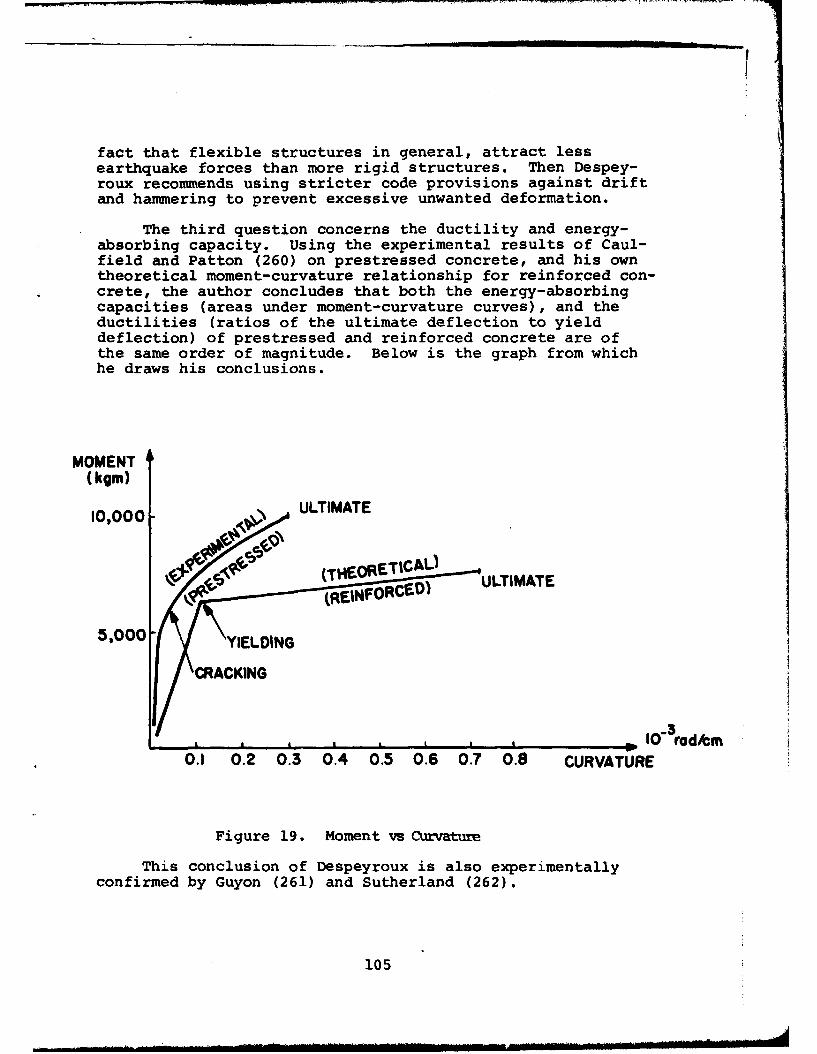
fact that flexible structures in general, attract lessearthquake forces than more rigid structures. Then Despey-roux recommends using stricter code provisions against driftand hammering to prevent excessive unwanted deformation.
The third question concerns the ductility and energy-absorbing capacity. Using the experimental results of Caul-field and Patton (260) on prestressed concrete, and his owntheoretical moment-curvature relationship for reinforced con-crete, the author concludes that both the energy-absorbingcapacities (areas under moment-curvature curves), and theductilities (ratios of the ultimate deflection to yielddeflection) of prestressed and reinforced concrete are ofthe same order of magnitude. Below is the graph from whichhe draws his conclusions.
MOMENT(kgm)
10,000- ULTIMATE
00 ýCp (THEORETICAL-!ULTIMATE
5,000-5,000 \YIELDING
•CRACKING
3, ' a t a I0 rod/em
0.1 0.2 0.3 0.4 0.5 0.6 0.7 0.8 CURVATURE
Figure 19. Moment vs Curvature
This conclusion of Despeyroux is also experimentallyconfirmed by Guyon (261) and Sutherland (262).
105
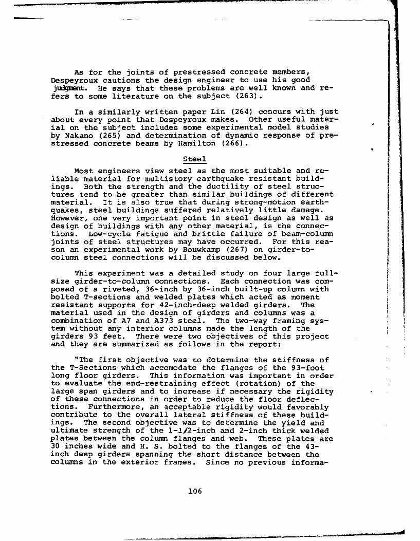
As for the joints of prestressed concrete members,Despeyroux cautions the design engineer to use his goodjudgment. He says that these problems are well known and re-fers to some literature on the subject (263).
In a similarly written paper Lin (264) concurs with justabout every point that Despeyroux makes. Other useful mater-ial on the subject includes some experimental model studiesby Nakano (265) and determination of dynamic response of pre-stressed concrete beams by Hamilton (266).
Steel
Most engineers view steel as the most suitable and re-liable material for multistory earthquake resistant build-ings. Both the strength and the ductility of steel struc-tures tend to be greater than similar buildings of differentmaterial. It is also true that during strong-motion earth-quakes, steel buildings suffered relatively little damage.However, one very important point in steel design as well asdesign of buildings with any other material, is the connec-tions. Low-cycle fatigue and brittle failure of beam-columnjoints of steel structures may have occurred. For this rea-son an experimental work by Bouwkamp (267) on girder-to-column steel connections will be discussed below.
This experiment was a detailed study on four large full-size girder-to-column connections. Each connection was com-posed of a riveted, 36-inch by 36-inch built-up column withbolted T-sections and welded plates which acted as momentresistant supports for 42-inch-deep welded girders. Thematerial used in the design of girders and columns was acombination of A7 and A373 steel. The two-way framing sys-tem without any interior columns made the length of thegirders 93 feet. There were two objectives of this projectand they are summarized as follows in the report:
"The first objective was to determine the stiffness ofthe T-Sections which accomodate the flanges of the 93-footlong floor girders. This information was important in orderto evaluate the end-restraining effect (rotation) of thelarge span girders and to increase if necessary the rigidityof these connections in order to reduce the floor deflec-tions. Furthermore, an acceptable rigidity would favorablycontribute to the overall lateral stiffness of these build-ings. The second objective was to determine the yield andultimate strength of the 1-1/2-inch and 2-inch thick weldedplates between the column flanges and web. These plates are30 inches wide and H. S. bolted to the flanges of the 43-inch deep girders spanning the short distance between thecolumns in the exterior frames. Since no previous informa-
106

tion was available about the strength of these welded platesas affected by residual stresses due to welding, two geomet-rically identical specimens of the types shown in Figures 2and 3 were to be investigated, one non-stress relieved andone stress relieved. Should the tests indicate the need forstress relieving, all girder to column connections were tobe treated to relieve the residual stresses."
The following was the test program:
"l. Specimen 1 (Type I, third floor connection, non-stress relieved),
2. Specimen 2 (Type I, third floor connection, stressrelieved),
3. Specimen 3 (Type II, fourteenth floor connection,non-stress relieved),
4. Specimen 4 (Type II, fourteenth floor connection,stress relieved) ."
The yield and ultimate loads for the welded plates wereas follows:
"Specimen 1. non-stress relieved; welded plate230x2 in.
Py=1800 k, fy=30 ksi; Pult=2 8 0 5 k, fult=4 7 ksi
Specimen 2. stress relieved; welded plate 30x2 in.
Py=2200 k, fy=37 ksi; Pult=2 7 5 0 k, f =46 ksiult ult=Specimen 3. non-stress relieved, welded plate
30xi-l/2 in.
Py=1400 k, fy=31 ksi; P ult=2200 k, f ult=49 ksi
Specimen 4. stress relieved; welded plate 30xi-i/2 in.
After load of 1600 k was reached end weld was cut
Pult=1 3 4 4 k, fshear ult= 4 4 ksi
"The results for Py indicated that the stress distri-bution in the moment plates was improved by stress relieving.Similar conclusions were derived from the stress distribu-tion along critical sections close to the welds. Thesewelds indicated that the distribution of the load over theseveral welds was better for the two stress relieved connec-tions than for the non-stress relieved specimens."
The prototype for this experiment was the HealthSciences Instruction and Research Buildings for the Univer-sity of California, San Francisco Medical Center, as
107

designed by Ried and Tarics, Architects and Engineers, SanFrancisco. This complex consists of two buildings: the MainEast Building which is 15 stories high and the West Buildingwhich is 16 stories. There is also a connecting corridorbetween the two buildings, two mechanical service towers,and an elevator tower. The Main East Building has been thesite for some more dynamic testing done by the Universityof California, Berkeley (268). These involve frequency re-sponse, time response, mode shapes, energy transfer, anddamping characteristics.
Some of the important conclusions are listed below:
1. "The steel frame of the service tower had very little effectan the dynamic behavior of the East Building in the summer of 1964, andthe East Building was tested virtually in isolation. However, when thesteel frame had been encased in concrete, the service tower did affectthe behavior of the East Building; in fact, both buildings then formeda new structural system. This interccnnected system had much largerdamping capacity then any of the isolated buildings."
2. "The increase of damping after the summer of 1964was caused mainly by the connections between buildings."
3. "A standard open frame model was found to reproduceaccurately the dynamical behavior of the East Building.This model was subjected to the ground acceleration recordof the El Centro earthquake. It was found that the amountof damping in the model played an important role in determin-ing the extent to which yielding occurred."
Damping of this building is discussed in more detail inreference (269).
Behavior of welded connections (270) and inelastic re-sponse of steel structures (271-275) also have applicationin the field of earthquake engineering.
More experimental research is necessary to determinethe properties and the behavior of materials. The parameterthat is used in the equations of motion, and the idealiza-tion that is made in the analysis, depend on the materialproperties to a great extent. Also as was mentioned earlier,the behavior of details and connections of structural ele-ments made from different materials, is very important.
The dynamic effect can be divided into two effects asapplied to materials. The first effect is that of the
108

strain rate t. As the strain rate increases, the yieldstress and the modulus of elasticity (very slightly) in-crease. However, this is much more pronounced in blast typeloadings and the increases can be ignored for earthquakeconsiderations. The second one is the effect of reversedaction or what may be called the Bauschinger effect. Thisresults in deterioration or decrease in both the yield stressand the modulus of elasticity. This is a problem in earth-quake-type loading and should be investigated further. Someliterature on the subject (276-280) is presently available.
Idealization of Mechanical Behavior
No matter what material is to be used, there must be anidealization of the material, the cross section, the member,and the structure. Nonlinear and inelastic idealizationsproved to be the most suitable for strong motion earthquake-resistant structural analysis. Therefore these topics havereceived considerable attention in recent years (13,14,281-288). It is well known that the damage due to repeated de-formations is cumulative and could lead to low-cycle fatiguefailures (81,82). Preliminary results indicate that it ispossible to have low-cycle fatigue failures of seismic struc-tures (18).
Below is a summary of different idealizations and theirdeviations from the "true behavior" (289).
The following relationships must be studied:
a vs. e for the material (stress vs. strain)
M vs. 0 for the cross section (moment vs. curvature)M vs. 0 for the member (moment vs. rotation)
H vs. 6 for the structure (load v-. deflection)
109
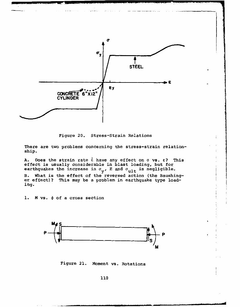
a"
C.y
eyCONCRETE 6"Xl2"11CYLINDER
Figure 20. Stress-Strain Relations
There are two problems concerning the stress-strain relation-ship.
A. Does the strain rate i have any effect on a vs. c? Thiseffect is usually considerable in blast loading, but forearthquakes the increase in ay, E and ault is negligible.
B. What is the effect of the reversed action (the Baushing-er effect)? This may be a problem in earthquake type load-ing.
1. M vs. • of a cross section
PP
Figure 21. Moment vs. Rotations
110
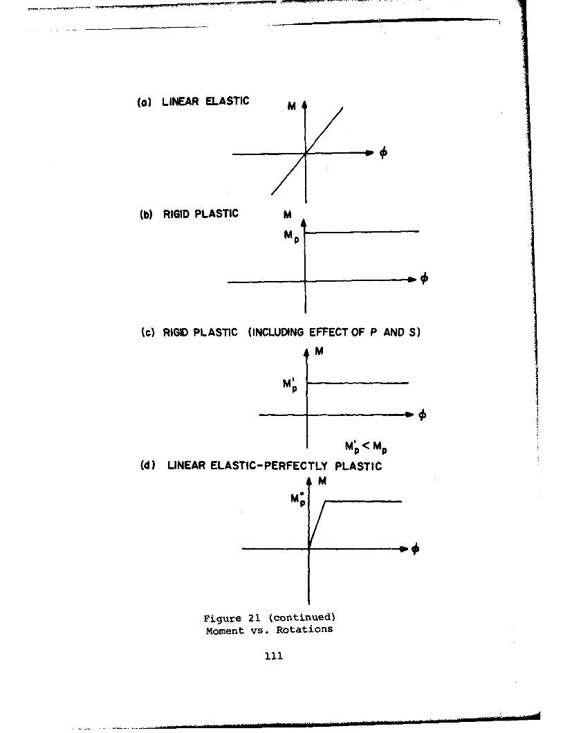
()LINEAR ELASTIC M
b)RIGID PLASTIC M
Mp4
()RIGID PLASTIC (INCLUDING EFFECT OF P AND S)
M
M p
M'<Mp
d)LINEAR ELASTIC- PERFECTLY PLASTICAN
M;
Figure 21. (continued)moment vs. Rotations

(s) LINEAR ELASTIC-PERFECTLY PLASTIC (WITH STRAIN HARDENING)
M
tI) RESIDUAL STRESSES INCLUDED
M
"(g) If) t STRAIN HARDENING
Figure 21 (continued)
Moment vs. Rotations
112
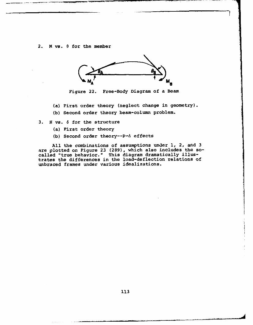
2. M vs. e for the member
KMA~Figure 22. Free-Body Diagram of a Beam
(a) First order theory (neglect change in geometry).
(b) Second order theory beam-column problem.
3. H vs. 6 for the structure
(a) First order theory
(b) Second order theory--P-A effects
All the combinations of assumptions under 1, 2, and 3are plotted on Figure 23 (289), which also includes the so-called "true behavior." This diagram dramatically illus-trates the differences in the load-deflection relations ofunbraced frames under various idealizations.
113

AFTER BERTERO (209)
Wo - - Mj~_ . SECONDOREELASTIC BUCKLING (LINEAR) (ELASTIC
(IIa, 2b, 3b)FIRST ORDER
w~w
(d) SIMPLE PLASTIC (0b,20,30)4 (9 ODIFIED SIMPLEPLSI e.03)
wpe FIRST: ORDER ELASTIC-PLASTIC
r SECOND ORDER RIGID-PLASTIC (Ico.,2a3SECOND ORDER ELASTIC- PLASTIC (Id,2b,3b) £'
wmGWm /, J (MECHANISM) TRUE BEHAVIORWm
r~TRUE BEHAVIORE
DEFLECTION,
Figure 23. Behavior of Unbraced Frames
114
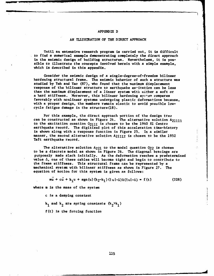
APPENDIX D
AN ILLUSTRATION OF THE DIRECT APPROACH
Until an extensive research program is carried out, it is difficultto find a numerical example demonstrating completely the direct approachin the seismic design of building structures. Nevertheless, it is pos-sible to illustrate the concepts involved herein with a simple example,which is described in this appendix.
Consider the seismic design of a single-degree-of-freedom bilinearhardening structural frame. The seismic behavior of such a structure wasstudied by Yeh and Yao (87), who found that the maximum displacementresponse of the bilinear structure to earthquake ex-itation can be lessthan the maximum displacement of a linear system with either a soft ora hard stiffness. Moreover, this bilinear hardening system comparesfavorably with nonlinear systems undergoing plastic deformations because,with a proper design, the members remain elastic to avoid possible low-cycle fatigue damage in the structure(18).
For this example, the direct approach portion of the design treecan be constructed as shown in Figure 24. The alternative solution A2 1 1 1 1to the excitation question Q2111 is chosen to be the 1940 El Centroearthquake record. The digitized plot of this acceleration time-historyis shown along with a response function in Figure 25. In a similarmanner, the second alternative solution A21112 is chosen to be the 1952Taft earthquake record.
The alternative solution A2 2 1 to the model question Q22 is chosento be a discrete model as shown in Figure 26. The diagonal bracings arepurposely made slack initially. As the deformation reaches a predeterminedvalue A, one of these cables will become tight and begin to contribute tothe frame stiffness. This structural frame can be represented by amechanical system with bilinear stiffness as shown in Figure 27. Theequation of motion for this system is given as follows:
mu + cu + klu + sgn(u)(k 2-kl)(Iu I-A)a(I uI-) = f(t) (228)
where m is the mass of the system
c is a damping constant
k and k2 are spring constants (k 2 >k 1 )
f(t) is the forcing function
115
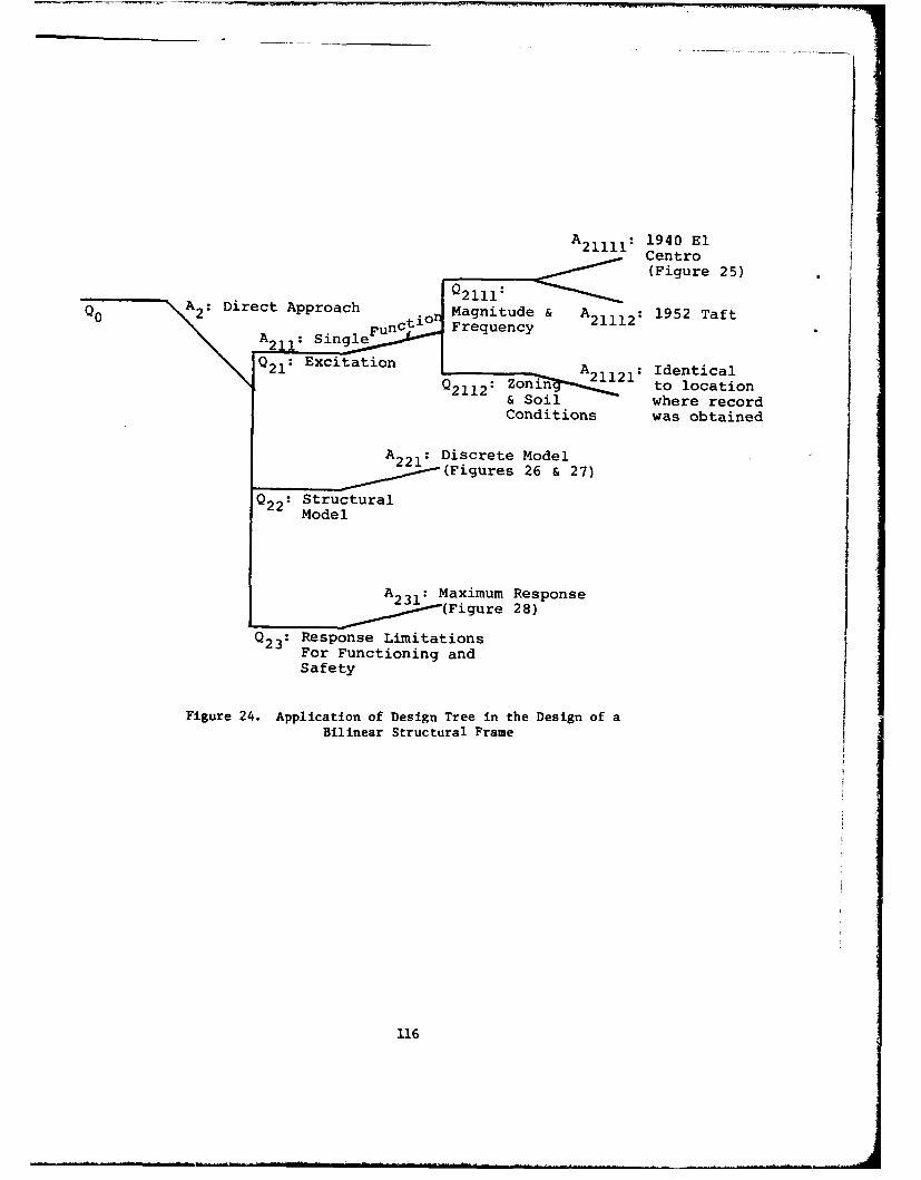
A 21111: 1940 ElCentro(Figure 25)
A irctAproch2111:
Q0 A2: ti. Magnitude & A21112: 1952 TaftA A211: Sing Fn rqec
Q21: Excitation A IdenticalQ211 2' zoin- to location
& Soil where recordConditions was obtained
A Discrete ModelFiur (Figures 26 & 27)
Q22: StructuralModel
A23.: Maximum Response~(Figure 28)
Q23: Response LimitationsFor Functioning andSafety
Figure 24. Application of Design Tree in the Design of aBilinear Structural Frame
116
Following Yeh and Yao (87)
Displacement Response
................ ........ ...... .....
..... TI.. .M
IIGround Acceleration
. .. ... ... .. ... . ..
Time, t, secondsReproduced from
[best available copyD
Figure 25. Acceleration Record of 1940 El Centro Earthquakeand a Typical Structural Response
k V 1 3.23 ,.Aad/e.
2 3.76 rad/sec.
Figure 26. One-Degree-of-Freedom Bilinear Structural System
117

[A-...- h2-k,
kk
DISPLACEMENT
Figure 27.. QOe-Degree-of-Freedom Bilinear Mechanical System
0.4
0..
o , 0.1 0.2 0. 3 Vi Ust
aE-o2
°01
--. .El Centro*-~.00
:0.0 oITaft"--"- ( socOasJ
Figure 28. Responses of Single-Degree-of Freedom Systemto El Centro and Taft Earthquakes
118
u is a variable denoting the displacement response
A is the distance at which the displacement-force relationship ispiecewise continuous.
_, if u>Osgn(u)u 0, if u-O
1-lif u<O
H(x) is the Heaviside step function
For convenience the following expressions are also introduced,
u MgSt k.
g is a gravitational constant
C2 ink.
For this particular case,¶rnm and were arbitrarily chosen to be 3.23rad/sec and 3.76 rad/sec, respectively, and E, a dimensionless dampingfactor, was assumed to be 0.0 and 0.0058.
Suppose that we are interested in selecting a design with the bestvalue of A/ust on the basis of maximum response A2 31 . Using the ContinuousSystem Modeling Program with an IBM 360/40 digital computer, the relation-ship between the maximum response and the nondimensionalized A was foundas shown in Figure 28. On this basis, the design engineer could choose avalue of A/ust of 0.05, which results in a maximum displacement of 0.2 ofthe corresponding static displacement Ust for zero damping and the 1940El Centro earthquake excitation.
This simple example is given herein to illustrate the concepts in-volved in the direct approach method, particularly the use of the design-tree in seismic design. As it is pointed out in the text of this report,the seismic design of building structures is a complex problem. Forexample, the proper choice of damping coefficients for various types ofbuildings is to be determined. Consequently, more research is requiredto make the direct approach really practical in seismic design.
1119

REFERENCES
1. Robert L. Wiegel, Coordinating Editor, Earthquake En-gineering, Prentice-Hall, 1970.
2. Earthquake Engineering Research, by the Committee onEarthquake Engineering Research, Division of Engineer-ing-National Research Council, National Academy of En-gineering, published by the National Academy of Sci-Sciences, Washington, D. C., 1969.
3. W. E. Fisher and D. H. Merkle, "The Great Alaska Earth-quake," Technical Report No. AFWL-TR-65-92, Air ForceWeapons Laboratory, Kirtland Air Force Base, New Mexico,November 1965.
4. F. J. Wood, Editor, The Prince William Sound, Alaska,Earthquake of 1964 and Aftershocks, V. I and II, U. S.Department of Commerce, Environmental' Sciences Services,Administration, Publication 10-3 (C & GS), 1967.
5. Robert D. Hanson and Henry J. Degenkolb, The VenezuelaEarthquake, July 29, 1967, American Iron and Steel In-stitute, New York, 1969.
6. "The Behavior of Reinforced Concrete Structures in theCaracas, Venezuela Earthquake of July 29, 1967," Port-land Cement Association (undated preliminary report).
7. M. A. Sozen, P. C. Jennings, R. B. Matthiesen, G. W.Housner, and N. M. Newmark, "Engineering Report on theCaracas Earthquake of 29 July 1967," National Academyof Sciences, Washington, D.C., 1968.
8. Uniform Building Code, 1967 Edition, Vol. I, Inter-national Conference of Building Officials, Pasadena,California.
9. Recommended Lateral Force Requirements, Seismology Com-mittee, Structural Engineers Association of California,1960, Revised, 1963, 1965, 1966.
10. Seismic Design for Buildings, TM 5-809-10, NAVDOCKS PP-355, AFM 88-3 (Chap. 13) , Departments of The Army,The Navy, and The Air Force, March 1966.
11. R. W. Clough, "Dynamics of Earthquakes," Journal ofStructural Division, ASCE, V. 86, April 1960, pp.4T9-65.
120

12. J. A. Blume, "Structural Dynamics in Earthquake Resis-tant Design," Trans. ASCE, Vol. 125, 1960, pp. 1088-1139.
13. A. S. Veletsos and N. M. Newmark, "Effect of InelasticBehavior on the Response of Simple Systems to Earth-quake Motions," Proceedings, 2nd World Conference inEarthquake Engineering, 1960, Japan.
14. J. Penzien, "Dynamic Response of Elasto PlasticFrames," Journal of the Structural Division, ASCE, Vol.86, July 1960, pp. 81-94.
15. P. C. Jennings, "Response of Simple Yielding Structuresto Earthquake Excitation," Earthquake Engineering Re-search Laboratory, California Institute of Technology,Pasadena, California, 1963.
16. S. C. Goel and G. V. Berg, "Inelastic Earthquake Re-sponse of Tall Steel Frames," Journal of the StructuralDivision, ASCE, Vol. 94, August 1968, pp. 1907-1934.
17. J. Penzien and S. C. Liu, "Non-Deterministic Analysisof Nonlinear Structures Subjected to Earthquake Exci-tations," Proceedings, Fourth World Conference onEarthquake Engineering, 1969.
18. I. Kasiraj and J. T. P. Yao, "Fatigue Damage in SeismicStructures," Journal of the Structural Division, ASCE,Vol. 95, No. ST8, August 1969, pp. 1673-1692.
19. G. W. Housner, "Characteristics of Strong MotionEarthquakes," Bulletin, Seismological Society of Amer-ica, Vol. 37, January 1947, pp. 19-31.
20. W. T. Thomson, "Spectral Aspects of Earthquakes,"Bulletin, Seismological Society of America, Vol. 49,No. 1, January 1959, pp. 91-98.
21. G. N. Bycroft, "White Noise Representation of Earth-quakes," Journal of the Engineering Mechanics Di-vision, ASCE, Vol. 86, No. EM2, Part 1, April 1960,pp. I"16.
22. J. L. Bogdanoff, J. E. Goldberg, and M. C. Bernard,"Response of a Simple Structure to a Random Earth-quake Type Disturbance," Bulletin, SeismologicalSociety of America, Vol. 51, April 1951, pp. 293-310.
121

23. J. E. Goldberg, J. L. Bogdanoff, and D. R. Sharpe,"The Response of Simple Nonlinear Systems to a RandomDisturbance of the Earthquake Type," Bulletin, Seis-mological Society of America, Vol. 54, No. 1, February1964, pp. 263-276.
24. Y. K. Lin, "Application of Nonstationary Shot Noise inthe Study of System Response to a Class of Nonstation-ary Excitation," Journal of Applied Mechanics, ASME,December 1963, pp. 555-558.
25. G. W. Housner and P. C. Jennings, "Generation of Arti-ficial Earthquakes," Journal of Engineering MechanicsDivision, ASCE, Vol. 90, No. EMi, February 1964, pp.113-150.
26. H. S. Ward, "Analog Simulations of Earthquake Motions,"Journal of the Engineering Mechanics Division, ASCE,Vol. 91, No. EM5, October 1965, pp. 173-190. i
27. M. Amin and A. H. S. Ang, "Non-Stationary StochasticModel of Earthquake Motions," Journal of the Engineer-ing Mechanics Division, ASCE, Vol. 94, No. EM2, April1968, pp. 559-583.
28. P. C. Jennings, G. W. Housner, and N. C. Tsai, "Simu-lated Earthquake Motions," Earthquake Engineering Re-search Laboratory, California Institute of Technology,Pasadena, California, 1968.
29. M. Shinozuka and Y. Sato, "Simulation of NonstationaryRandom Process," Journal of the Engineering MechanicsDivision, ASCE, Vol. 93, No. EMl, February 1967, pp.11-40.
30. 0. A. Rascon and C. A. Cornell, "Strong Motion Earth-quake Simulation," Report No. R68-15, Department ofCivil Engineering, Massachusetts Institute of Tech-nology, 1968.
31. R. Levy, Random Process for Earthquake Simulation,Ph.D. Thesis, Polytechnic Institute of Brooklyn, 1969.
32. S. Hou, "Earthquake Simulation Models and Their Appli-cations," Report No. R68-17, Department of Civil En-gineering, Massachusetts Institute of Technology,1968.
33. R. N. Iyengar and K. T. S. R. Iyengar, "A Nonstationary
122
Random Process Model for Earthquake Accelerograms,"Bulletin, Seismological Society of America, Vol. 59,No. 3, June 1969, pp. 1163-1188.
34. Paul H. Wirsching and J. T. P. Yao, "Response of Bi-linear Hardening Systems to Earthquake-like Excitation,"Technical Report CE-19(69)NSF-065, Bureau of Engineer-ing Research, The University of New Mexico, Albuquerque,New Mexico, November 1969.
35. E. Rosenblueth, "Probabilistic Design to Resist Earth-quakes," Journal of the Engineering Mechanics Division,ASCE, Vol. 90, No. EM5, October 1940, pp. 189-220.
36. J. R. Benjamin, "Probabilistic Model for Seismic ForceDesign," Journal of the Structural Division, ASCE, Vol.94, No. ST5, May 1968, pp. 1175-1196.
37. C. A. Cornell, "Engineering Seismic Risk Analysis,"Bulletin, Seismological Society of America, Vol. 58,No. 5, October 1968, pp. 1583-1606.
38. M. Shinozuka, "Methods of Safety and Reliability Anal-ysis," Technical Report No. 1 (NSF Grant No. GK-3585),Department of Civil Engineering and Engineering Mechan-ics, Columbia University, July 1969.
39. Paul H. Wirsching and J. T. P. Yao, "Distribution ofResponse to Simulated Earthquakes," Technical Note,Journal of the Engineering Mechanics Division, ASCE,Vol. 96, No. EM4, August 1970, pp. 515-520.
40. F. Bleich and E. Melan, "Die gewohnlichen und PartiellenPartiellen Differenzengleichyngen der Baustah'k,"Julius Springer, Berlin, 1927.
41. T. Wah, "Natural Frequencies of Uniform Grillages,"Trans., Journal of Applied Mechanics, ASME, December1963, pp. 571-578.
42. K. R. Leimback and D. McDonald, "Free Vibration of Two-Dimensional Frameworks," Trans., ASCE, Vol. 96, No.ST2, February 1970, pp. 2W7V0.
43. Ellington and McCallion, "The Free Vibration of Grill-ages," Trans., ASME, December 1959, pp. 603-607.
44. Dean, D. L., and Ugarte, C. P., "Field Solutions forTwo Dimensional Frameworks," International Journal ofMechanical Science, Vol. 10, 1968, pp. 315-339.
123
45. "Earthquake Investigations in California, 1934-35,"Special Publication No. 201, U. S. Department of Com-merce, Washington, D. C.
46. G. W. Housner and A. G. Brady, "Natural Periods of Vi-brations of Buildings," Journal of the EngineeringMechanics Division, ASCE, Vol. 89, EM4, August 1963.
47. R. W. Clough, "Dynamic Effect of Earthquakes," Trans.ASCE, Part II, Vol. 126, 1961.
48. M. G. Salvadori and E. Heer, "Periods of Framed Build-ings for Earthquake Analysis," Trans. ASCE, Vol. 127,Part I, 1962.
49. R. W. Clough, Class Notes in Structural Dynamics II,University of California, Berkeley, Spring 1969.
50. J. A. Blume, N. M. Newmark, and L. H. Corning, "De-sign of Multistory Reinforced Concrete Buildings forEarthquake Motions," Portland Cement Association,1961.
51. C. F. Richter, "Seismic Regionalization," Bulletin ofSeismological Society of America, Vol. 49, No. 2,April 1959.
52. E. B. Roberts and F. P. Ulrich, "Seismological Activ-ities of the U. S. Coast and Geodetic Survey in 1948,"Bulletin of Seismological Society of America, Vol.40, 1950.
53. E. B. Roberts and F. P. Ulrich, "Seismological Activ-ities of the U. S. Coast and Geodetic Survey in 1949,"Bulletin of Seismological Society of America, Vol. 41,1951.
54. R. W. Clough, "Earthquake Analysis by Response SpectrumSuperposition," Bulletin of Seismological Society ofAmerica, Vol. 52, No. 3, 1962.
55. J. Despeyroux, "The New French Aseismic Code," Proc.of 3WCEE, Vol. III, New Zealand, 1965.
56. "Translations in Earthquake Engineering," EarthquakeEngineering Research Institute, San Francisco, Cali-fornia, 1960.
124
57. G. P. Gorshkov et al. "Seismic Regionalization of theTerritory of the USSR and the Problems of AntiseismicConstruction" (in Russian); in Jubilee Symposium onthe 30th Anniversary of the Great October SocialisticRevolution, Academy of Sciences, Moscow, 1947 (citedfrom reference 10).
58. I. E. Gubin, "On Some Questions of Seismic Regionali-zation" (in Russian), Akad. Nauk SSSR Trudy geo-fizicheskogo instituta, No. 25 (152), 1954 (cited fromreference 10).
59. S. V. Medvedev, "New Seismic Regionalisation of USSRTerritory," Proc. of ý'CPE, Vol. I, New Zealand, 1965.
60. E. Rosenblueth, "Aseismic Provisions for the FederalDistrict, Mexico," Proc. of 2WCEE, Vol. III, 1960.
61. L. E. Goodman, E. Rosenblueth, and N. Newmark, "Aseis-mic Design of Firmly Founded Elastic Structures," Trans.ASCE, 120, 1955.
62. A. Beles, "The Problem of Engineering Seismology inRomania," Proc. of the International Seminar on Earth-quake Engineering, Skopje, 1964.
63. "Aseismic Design and Testing of Nuclear Facilities,"Technical Report, Series 88, International AtomicEnergy Agency, Vienna, 1968.
64. "Regulations for Construction in Regions of Hazard,"Ministry of Housing and Construction, Turkey, 1968(in Turkish).
65. I. Alpan, "Earthquake Engineering in Israel," Proc.of the International Seminar on Earthquake Engineering,Skopje, 1964.
66. J. I. Bustamante, "Seismic Shears and OverturningMoments in Buildings," Proc. of 3WCEE, Vol. III, 1965.
67. G. W. Housner and H. Outinen, "The Effect of TorsionalOscillations on Earthquake Stresses," Bulletin ofSeismological Society of America, Vol. 48, July 1958.
68. J. I. Bustamante and E. Rosenblueth, "Building CodeProvisions for Torsional Oscillations," 2WCEE, Vol.II, 1960.
125

69. T. Shiga, "Torsional Vibration of Multistoried Build-ings," Proc. of 3WCEE, Vol. II, New Zealand, 1965.
70. R. I. Skinner, D. W. C. Skilton, and D. A. Laws, "Un-balanced Buildings and Buildings with Light Towersunder Earthquake Forces," Proc. 3WCEE, Vol. II, NewZealand, 1965.
71. "Building Code Requirements for Reinforced Concrete,"ACI, 318-63.
72. J. Penzien and A. K. Chopra, "Earthquake Response ofAppendage on Multistory Building," Proc. 3WCEE, Vol.II, New Zealand, 1965.
73. C. W. Housner, "Vibration of Structures Induced bySeismic Waves," Shock and Vibration Handbook (Harrisand Crede), Chap. 50, McGraw-Hill, New York, 1961.
74. H. P. Pittelko, "Vertical Forces in the Alaska Earth-quake," Civil Engineering ASCE, January 1965.
75. I. K. McIvor, "Dynamic Stability of Axially VibratingColumns," Jour. ASCE, Vol. 90, EM6, December 1965.
76. K. Kanai and S. Yoshizawa, "On the Period of Damping ofVibration in Actual Buildings," Bulletin, EarthquakeResearch Institute, University of Tokyo, Vol. 39, Part3, Sept. 61.
77. A. Arias and R. Husid, "Empirical Formula for the Com-putation of Natural Periods," Reinsta del IDIEM, Vol.1, University of Chile, March 62.
78. N. N. Nielsen, "Earthquake Engineering Research Digest1970," Civil Engr. Dept., Univ. of Ill., Urbana, Ill.
79. M. Asimow, Introduction to Design, Prentice-Hall, 1962.
80. N. M. Newmark, "Current Trends in the Seismic Analysisand Design of High-Rise Structures," Earth uake Engi-neering, Edited by Robert L. Wiegel, Prentice-Hall,1970, pp. 403-424.
81. J. T. P. Yao and W. H. Munse, "Low-Cycle Axial FatigueBehavior of Mild Steel," Special Technical Publication,ASIM, N. 338, 1962, pp. 5-24.
82. J. T. P. Yao and W. H. Munse, "Low Cycle Fatigue ofMetals-Literature Review," Welding Journal, Research
3.26

Supplement, Vol. 41, No. 4, April 1962, pp. 182s-193s.
83. W. Zuk, "Kinetic Structures," Civil Engineering, ASCE,December 1968, pp. 62-64.
84. R. N. Wright, "Active Systems for Increased StructuralResistance to Exceptional Loads," Department of CivilEngineering, University of Illinois, Urbana, Illinois,January 1968.
85. W. J. Nordell, "Active Systems for Blast-ResistantStructures," Technical Report R-611, Naval Civil En-gineering Laboratory, Port Hueneme, California, Febru-ary 1969.
86. J. T. P. Yao, "Adaptive Systems for Earthquake-Resis-tant Structures," presented at the Structural ResearchSession, ASCE Structural Conference, Louisville, Ken-tucky, April 14-18, 1969 (Preprint 865).
87. H. Y. Yeh and J. T. P. Yao, "Response of BilinearStructural Systems to Earthquake Loads," presented atthe ASME Vibrations Conference, Philadelphia, Pennsyl-vania, March 30-April 2, 1969 (Paper 69 VIBR-20).
88. H. Y. Yeh and J. T. P. Yao, "Random Response of Piece-wise Linear Systems to White Noise Excitation," Tech-nical Report CE-17 (69) NSF-065, Bureau of EngineeringResearch, The University of New Mexico, Albuquerque,New Mexico, September 1969.
89. P. H. Wirsching and J. T. P. Yao, "A Statistical Studyof Some Design Concepts in Earthquake Engineering,"Technical Report CE-21 (70) NSF-065, Bureau of Engi-neering Research, The University of New Mexico, Albu-querque, New Mexico, May 1970.
90. W. H. Middendorf, Engineering Design, Allyn and Bacon,1969.
91. W. E. Eder, "Definitions and Methodologies," The DesignMethod, Edited by S. A. Gregory, Plenum Press, NewYork, 1966, pp. 19-31.
92. A. Newell and H. A. Simon, "Problem-Solving Machines,"Int. Sci. Technol. Vol. 12, 1964, pp. 48-9, 53-62.
93. K. W. Norris, "The Morphological Approach to Engineer-ing Design," Conference on Design Methods, Edited byJ. C. Jones and D. G. Thornley, Pergamon, Oxford, 1963.
127
94. Rudolf F. Dzenick, "Model-Free Design of Aseism~cStructures," Journal of the Engineering Mechanics Di-vision, ASCE, Vol. 96, No. EM4, August 1970, pp. 483-493.
95. M. Shinozuka, "Maximum Structural Response to SeismicExcitations," Journal of the Engineering MechanicsDivision, ASCE, Vol. 96, No. EM5, October 1970, pp.7T9-738.
96. J. C. Snowdon, Vibration and Shock in Damped MechanicalSystems, Wiley, 1968.
97. B. J. Lazan, Damping of Materials;and Members in Struc-tural Mechanics, Pergamon Press, 1968.
98. R. W. Clough, "Earthquake Response of Structures,"Earthquake Engineering, Edited by Robert L.,Wiegel,Prentice-Hall, 1970, pp. 307-328.
99. Myron Tribus, Rational Descriptions, Decisions, andDesigns, Pergamon Press, 1969.
100. N. H. Burns and C. P. Siess, "Repeated and ReversedLoading in Reinforced Concrete," Journal of theStructural Division, ASCE, Vol. 92, No. ST5, October1966, pp. 65-78.
101. Egor P. Popov and R. B. Pinkney, "Cyclic Yield Reversalin Steel Building Connections," Journal of the Struc-Division, Vol. 95, No. ST3, March 1969, pp. 327-353.
102. J. P. Tang and J. T. P. Yao, "Random Fatigue--A Litera-ture Review," Technical Report No. CE-22(70) NSF-065,'Bureau of Engineering Research, The University of NewMexico, Albuquerque, New Mexico, July 1970.
103. S. R. Swanson, "Random Load Fatigue Testing: A State
of Art Survey," Materials Research and Standards,ASTM, April 1968, pp. 10-44.
104. A. M. Freudenthal, "Safety of Structures," Trans-actions, ASCE, Vol. 112, 1947, pp. 125-180, or Pro-ceedings, ASCE, October 1945.
105. A. M. Freudenthal, J. M. Garrelts, and M. Shinozuka,"The Analysis of Structural Safety," Journal of theStructural Division, ASCE, Vol. 92, No. ST1, February1966, pp. 267-325.
I28

106. A. H.-S. Ang and M. Amin, "Safety Factors and Proba-bility in Structural Design," Journal of the Struc-tural Division, ASCE, Vol. 95, No. ST7, July 1969,pp. 1389-1405.
107. A. H.-S. Ang, "Extended Reliability Basis of Struc-tural Design Under Uncertainties," Annals of the 9thReliability and Maintainability Conference, SAE/AIAA/ASME, Detroit, July 1970.
108. J. R. Benjamin, "Probabilistic Models for SeismicForce Decisions," Journal of the Structural Division,Vol. 94, No. ST7, July 1968, pp. 1665-1679.
109. J. R. Benjamin, "Probabilistic Models for SeismicForce Decisions," Journal of the Structural Division,ASCE, Vol. 94, No. ST5, May 1968, pp. 1175-1196.
110. C. Jordan, Calculus of Finite Differences, ChelseaPublishing Co., 1947.
111. E. Pinney, Ordinary Difference-Differential Equations,University of California Press, 1958.
112,. R. Manvi, G. E. Duvall, and S. C. Lowell, "Finite Am-plitude Longitudinal Waves in Lattices," Int. Journalof Mechanical Sciences, Vol. 11, 1969.
113. N. N. Lebedev, Special Functions and Their Applica-tions, translated by R. A. Silverman, Prentice-Hall,1965.
114. D. L. Dean, "On the Techniques of Discrete Field Solu-tions," Proceedings, ASCE EMD Specialty Conference atRaleigh, N. C., November 8-10, 1967, pp. 61-65.
115. Y. K. Lin, I. D. Brown, and P. C. Deutchile, "FreeVibrations of a Finite Row of Continuous Skin-StringerPanels," Journal of Sound and Vibration, Vol. I, 1964,pp. 14-27.
116. C. Omid'varan, "Contribution to Analysis of UnbracedRigid Frames," to appear in the Journal of Mathe-matics (ZAMM).
117. C. Omid'varan, "Discrete Energy Theorem," to appear inthe Journal of Mathematics and Mechanics (ZAMM).
129
118. C. Omid'varan, "Discrete Analysis of Latticed Col-umns," Journal of Structural Division, ASCE, Vol. 94,No. ST1, January 1968.
119. W. Guthowski, "The Stability of Latticed Struts,"Journal of Mathematics and Mechanics (ZAMM), Vol. 43,1963.
120. D. L. Dean, "On the Statics of Latticed Shells," Vol.25, 1965, pp. 65-81.
121. D. L. Dean, "Lamella Beams and Grids," Journal ofEngineering Mechanics Division, ASCE, April 1964,pp. 107-129.
122. D. L. Dean and C. P. Ugarte, "Analysis of StructuralNets," Int. Association for Bridge and Structural En-gineering, Vol. 23, 1963, pp. 201-220.
123. C. P. Ugarte, Closed Analysis of Latticed StructuralShells, Ph.D. dissertation, University of Delaware,
124. C. P. Ugarte and D. L. Dean, Discussion of "Analysisof Laterally Loaded Gridworks" by T. Wah, Journal ofEn ineering Mechanics Division, ASCE, Vol. 90, No.EM6, December 1964, pp. 265-274.
125. D. L. Dean and C. Omid'varan, "Analysis of RibbedPlates," Journal of Structural Division, ASCE, Vol.95, No. ST3, March 1969.
126. D. L. Dean and R. Ganga, "Macro Approach to DiscreteField Analysis," Journal of Engineering MechanicsDivision, ASCE, Vol. 96, No. EM4, August 1970.
127. D. L. Dean, "Analysis of Curbed Lattices with Gener-alized Joint Loading," Int. Association for Bridgeand Structural Engineering, Vol. 20, 1960.
128. D. L. Dean and S. Tauber, "Solution for One-7"imen-sional Structural Lattices," Journal of EngineeringMechanics Division, Vol. 85, No. EM4, October 1959,pp. 31-41.
129. D. L. Dean and S. Tauber, Discuasion of "Analysis ofRigid Frames by Difference Equations" by Tsang,Journal of Structural Division, ASCE, Vol. 89, No.ST5, 1963, pp. 351-361.
130

130. G. W. Housner, "Strong Ground Motion," EarthquakeEngineering, Edited by Robert L. Wiegel, Chapter 4,Prentice-Hall, 1970, pp. 75-91.
131. Y. K. Lin, Probabilistic Theory of Structural Dy-namics, McGraw-Hill, 1967.
132. E. Rosenblueth, "Some Applications of ProbabilityTheory in Aseismic Design," Proceedings, World Con-ference on Earthquake Engineering, Berkeley, Calif.,June 1956.
133. E. Rosenblueth and J. I. Bustamante, "Distribution ofStructural Responses to Earthquakes," Journal of theEngineering Mechanics Division, ASCE, Vol. 88, No. EM3,June 1962.
134. G. W. Housner, "Behavior of Structures During Earth-quakes," Journal of the Engineering Mechanics Division,ASCE, Vol. 85, No. EM4, October 1959, pp. 109-129.
135. K. Kanai, "Some Empirical Formulas for the SeismicCharacteristics of the Ground," Bulletin, EarthquakeResearch Institute, Tokyo, Japan, Vol. 35, 1957,pp. 309-325.
136. H. Tajimi, "A Statistical Method of Determining theMaximum Response of a Building During an Earthquake,"Proceedings, 2nd World Conference on Earthquake Engi-neering, Tokyo, Japan, 1960.
137. T. K. Caughey and H. J. Stumpf, "Transient Responseof a Dynamic System Under Random Excitation," Journalof Aplied Mechanics, ASME, Vol. 28, No. 4, December1961, pp. 563-566.
138. E. Parzen, Stochastic Processes, Holden-Day, 1962,pp. 144-157.
139. C. Allin Cornell, "Stochastic Process Models in Struc-tural Engineering," Technical Report No. 34, Depart-ment of Civil Engineering, Stanford University, Stan-ford, California, May 1964.
140. J. L. Alford, G. W. Housner, and R. R. Martel, "Spec-trum Analysis of Strong Motion Earthquakes," Earth-quake Engineering Research Laboratory, CaliforniFaIn-stitute of Technology, Pasadena, California, August1964.
131

141. T. Naka, T. Kato, and M. Yuasa, "Dynamical Analysis ofSteel Structures by Electronic Analogy," Third WorldConference in Earthquake Engineering Proceedings, Vol.II, 1965, pp. 385-389.
142. M. J. Murphy, G. N. Bycroft, and L. W. Harrison,"Electrical Analogy for Earthquake Shear Stresses,"Third World Conference in Earthquake Engineering Pro-ceedings, 1965.
143. H. C. Merchant and D. E. Hudson, "Mode Superpositionin Multidegree of Freedom Systems Using EarthquakeResponse Spectrum Data," Bulletin of the SeismologicalSociety of America, Vol. 52, No. 2, April 1962, pp.405-416.
144. S. Cherry and A. G. Brady, "Determination of StructuralDynamic Properties of Statistical Analysis of RandomVibrations," Proceedings, Third World Conference inEarthquake Engineering, January 1965.
145. A. G. Brady, "Studies of Response to Earthquake GroundMotion," Earthquake Engineering Research Laboratory,California Institute of Technology, Pasadena, Cali-fornia, 1966.
146. Paul H. Wirsching and J. T. P. Yao, "Analog Simulationof Earthquake Motions," Technical Report CE-12(68)NSF-065, Bureau of Engineering Research, The University ofNew Mexico, Albuquerque, New Mexico, November 1968.
147. G. A. Korn, Random-Process Simulation and Measurements,McGraw-Hill, 1966.
148. V. V. Bolotin, Statistical Methods in Structural Me-chanics, Holden Day, 1969.
149. S. H. Crandall, Random Vibration, Vol. 1, MIT Press,Cambridge, Massachusetts, 1958.
150. S. H. Crandall, Random Vibration, Vol. 2, MIT Press,Cambridge, Massachusetts, 1963.
151. S. H. Crandall and W. D. Mark, Random Vibration inMechanical Systems, Academic Press, 1963.
152. Richard H. Lyon, Random Noise and Vibration in SpaceVehicles, Shock and Vibration Information Center,U.S. Department of Defense, 1967.
132
153. J. D. Robson, An Introduction to Random Vibration,Edinburgh at the University Press, 1963.
154. J. L. Bogdanoff, J. E. Goldberg, and A. J. Schiff,"The Effect of Ground Transmission Time on the Re-sponse of Long Structures," Report No. 8, Ser. 1,Center of Applied Stochastics, Purdue University,Lafayette, Indiana, 1964.
155. M. Shinozuka, M. Hakuno, and H. Itagaki, "Response ofa Multi-Story Frame Structure to Random Excitation,"Technical Report No. 29, Institute for the Study ofFatigue and Reliability, Department of Civil Engineer-ing and Engineering Mechanics, Columbia University,February 1966.
156. M. Shinozuka and J. N. Yang, "Random Vibration ofLinear Structures," Technical Report No. 53, The In-stitute for the Study of Fatigue and Reliability, De-partment of Civil Engineering and Engineering Mechan-ics, Columbia University, November 1967.
157. J. N. Yang and M. Shinozuka, "Numerical Fourier Trans-form in Random Vibration," Journal of the EngineeringMechanics Division, ASCE, Vol. 95, No. EM3, June 1969,pp. 731-746.
158. M. Shinozuka, "Random Processes with EvolutionaryPower," Technical Report No. 4 (NSF Grant No. GK-3858),Department of Civil Engineering and Engineering Me-chanics, Columbia University, September 1969.
159. P. W. Brant and M. Shinozuka, "Application of theEvolutionary Power Spectrum in Structural Dynamics,"Technical Report No. 3 (NSF Grant No. GK-3858), De-partment of Civil Engineering and Engineering Mechan-ics, Columbia University, September 1969.
160. S. H. Crandall, "Random Vibration of a Nonlinear Sys-tem with a Setup Spring," Journal of Applied Mechan-ics, ASME, Vol. 29, September 1962, pp. 477-482.
161. T. K. Caughey, "Derivation and Application of the Fok-ken-Planck Equation to Discrete Nonlinear DynamicSystems Subjected to White Random Excitation," TheJournal of the Acoustical Society of America, VoT.35, No. 11, November 1963, pp. 1683-1692.
133
162. T. K. Caughey, "Equivalent Linearization Techniques,"The Journal of the Acoustical Society of America, Vol.35, No. 11, November 1963, pp. 1706-1711.
163. S. H. Crandall, "Zero Crossings, Peaks, and Other Sta-tistical Measures of Random Responses," The Journal ofthe Acoustical Society of America, Vol. 35, No. 11,November 1963, pp. 1693-1699.
164. S. H. Crandall, "Perturbation Techniques for RandomVibration of Nonlinear Systems," The Journal of theAcoustical Society of America, Vol. 35, No. 11, Novem-ber 1963, pp. 1700-1705.
165. R. H. Lyon, "Empirical Evidence for Nonlinearity andDirections for Future Work," The Journal of the Acous-tical Society of America, Vol. 35, No. 11, November1963, pp. 1712-1721.
166. T. K. Caughey and J. K. Dienes, "Analysis of a Non-linear First-Order System with a White Noise Input,"Journal of Applied Physics.. Vol. 32, 1961, pp. 2476-2479.
167. H. Y. Yeh and J. T. P. Yao, "Random Response of Piece-wise Linear Systems to White Noise Excitation," Tech-nical Report Ce-17(69)NSF-065, Bureau of EngineeringResearch, The University of New Mexico, Albuquerque,New Mexico, September 1969.
168. S. 0. Asplund, "The Risk of Failure," Structural En-gineer, Vol. 36, No. 8, August 1958.
169. C. B. Brown, "Concepts of Structural Safety," Journalof the Structural Division, ASCE, Vol. 86, No. ST12,December 1960, pp. 39-57.
170. A. M. Freudenthal and M. Shinozuka, "Structural Safetyunder Conditions of Ultimate Load Failure and Fa-tigue," WADD Tech. Report 61-177, October 1961.
171. M. Shinozuka, "On the Reliability Analysis of Mechan-ical Systems," Proceedings, The Fifth InternationalSymposium on Space Technology and Science, Tokyo,Japan, September 1963, pp. 943-954.
172. C. A. Cornell, "Bounds on the Reliability of Struc-tural Systems," Journal of the Structural Division,ASCE, Vol. 93, No. ST1, February 1967, pp. 171-200.
134

173. A. H. S. Ang and M. Amin, "Reliability of Structures
and Structural Systems," Journal of the Structural-Division, ASCE, Vo.. 94, No. EM2, April 1968, pp.
174. M. Shinozuka, J. T. P. Yao, and A. Nishimura, "On theReliability of Redundant Structures," Proceedins,The Sixth International Symposium on Space Technologyand Science, Tokyo, Japan, December 1965, pp. 431-438.
175. M. Shinozuka and H. Itagaki, "On the Reliability ofRedundant Structures," Annals of Reliability andMaintainability, Vol. 5, July 1966, pp. 605-610.
176. J. T. P. Yao and H. Y. Yeh, "Safety Analysis of Sta-tically Indeterminate Trusstes," Annals of Relia-bility and Maintainability, Vol. 6, July 1967, pp.54-62.
177. J. T. P. Yao and H. Y. Yeh, "Formulation of StructuralReliability," Journal of Structural Division, ASCE,Vol. 95, No. ST12, December 1969.
178. J. L. Jorgenson and J. E. Goldberg, "Probability ofPlastic Collapse Failure," Journal of Structural Di-vision, ASCE, Vol. 95, No. ST8, August 1969, pp.1743-1761.
179. H. Hilton and M. Feigen, "Minimum Weight AnalysisBased on Structural Reliability," Journal of AerospaceSciences, Vol. 27, 1960, pp. 641-652.
180. R. Kalaba, "Design of Minimal-Weight Structures forGiven Reliability and Cost," Journal of AerospaceSciences, Vol. 29, March 1962, pp. 355-356.
181. W. C. Broding, F. W. Diederich, and P. S. Parker,"Structural Optimization and Design Based on a Relia-bility Criterion," Journal of Spacecraft Rockets, Vol.1, No. 1, January 1964, pp. 56-61.
182. F. Moses and D. E. Kinser, "Optimum Structural Designwith Failure Probability Constraints," AIAA Journal,Vol. 5, No. 6, June 1967, pp. 1152-1158.
183. M. Shinozuka and J. N. Yang, "Optimum Structural De-sign Based on Reliability and Proof-Load Testing,"Tech. Report 32-1402, Jet Propulsion Laboratory,Pasadena, California, June 15, 1969.
135
184. M. Shinozuka, J. N. Yang, and E. Heer, "Optimum Struc-tural Design Based on Reliability Analysis," Proceed-ings, The Eighth International Sympcsium on SpaceTechnology and Sciences, Tokyo, Japan, August 25-30,1969, pp. 245-258.
185. P. C. Jennings and R. Husid, "Collapse of YieldingStructures During Earthquakes," Journal of Engineer-ing Mechanics Division, ASCE, Vol. 94, No. EM5,October 1968, pp. 1045-1065.
186. M. Shinozuka, "Probability of Structural Failure UnderRandom Loading," Journal of the Engineering MechanicsDivision, ASCE, Vol. 90, No. EM5, October 1964, pp.147-170.
187. M. Shinozuka and J. T. P. Yao, "On the Two-Sided Time-Dependent Barrier Problem," Journal of Sound andVibration, Vol. 6, No. 1, 1967, pp. 98-104.
188. M. Shinozuka, H. Itazuki, and M. Hakuno, "DynamicSafety Analysis of Multistory Buildings," Journal ofthe Structural Division, ASCE, Vol. 94, No. ST1,January 1968, pp. 309-330.
189. M. Shinozuka, "On the Two-Sided Barrier Problem,"Journal of Applied Probability, Vol. 2, 1965, pp.79-87.
190. J. N. Yang and M. Shinozuka, "On the Bound of FirstExcursion Probability," Technical Report 32-1304, JetPropulsion Laboratory, California Institute of Tech-nology, Pasadena, California, August 15, 1968.
191. M. Shinozuka and J. N. Yang, "On the Bound of FirstExcursion Probability," Journal of the EngineeringMechanics Division, ASCE, Vol. 95, No. EM2, April1969, pp. 363-377.
192. M. Shinozuka and J. N. Yang, "On First-ExcursionsProbability in Stationary Narrow-Band Random Vibra-tion," Technical Report No. 6, Department of CivilEngineering and Engineering Mechanics, ColumbiaUnicersity, New York, March 1970.
193. J. N. Yang and M. Shinozuka, "First Excursion Failureof Structures Under Random Excitation," Technical Re-port No. 7, Department of Civil Engineering and En-gineering Mechanics, Columbia University, New York,June 1970.
136

194. Y. K. Lin, "On First-Excursion Failure of RandomlyExcited Structures," AIAA Journal, Vol. 8, No. 4,April 1970, pp. 720-725.
195. A. L. Sweet, "Upper Bound for Two-Sided Barrier Prob-lem," Journal of the Engineering Mechanics Division,ASCE, Vol. 95, No. EM6, December 1969, pp. 1369-1378.
196. S. Lubkin and J. J. Stoker, "Stability of Columns andStrings Under Periodically Varying Forces," guarterlyApplied Mathematics, Vol. 1, No. 3, October 1943.
197. L. A. Pipes, "Dynamic Stability of a Uniform StraightColumn Excited by a Pulsating Load," Journal of theFranklin Institute, Vol. 277, June 1964.
198. I. K. McIvor, "Dynamic Stability of Axially VibratingColumns," Journal of the Engineering Mechanics Di-vision, ASCE, Vol. 90, No. EM6, December 1964.
199. N. F. Morris, "Dynamic Stability of a Beam-Column witha Fixed Distance Between Supports," Journal of theFranklin Institute, Vol. 280, No. 2, August 1965.
200. V. V. Bolotin, Dynamic Stability of Elastic Systems,Holden-Day, 1964.
201. S. P. Timoshenko and J. M. Gere, Theory of ElasticStability, McGraw-Hill, 1961, pp. 158-162.
202. H. Ziegler, Principles of Structural Stability,Blaisdell, 1966, pp. 139-143.
203. S. T. Ariaratnam, "Dynamic Stability of a Column UnderRandom Loading," from Dynamic Stability of Structures(edited by G. Herrmann), Pergamon Press, 1967.
204. F. Kozin, "On Almost Sure Stability of Linear Systemswith Random Coefficients," Journal of Mathematics andPhysics, Vol. XLII, No. 1, March 1963.
205. T. K. Caughey and A. H. Gray, "On the Almost SureStability of Linear Dynamic Systems with StochasticCoefficients," Journal of Applied Mechanics, ASME,Vol. 32, No. 2, June 1965, pp. 365-372.
206. T. K. Caughey and J. R. Dickerson, "Stability of Lin-ear Dynamic Systems with Narrow Band Parametric Ex-citation," Journal of Applied Mechanics, ASME, Vol.34, No. 3, September 1967, pp. 709-713.
137
207. Paul H. Wirsching and J. T. P. Yao, "Stability ofColumns Subjected to a Random Axial Load," TechnicalReport CE-20(69)NSF-065, Bureau of Engineering Re-search, The University of New Mexico, Albuquerque,New Mexico, November 1969.
208. I. Kasiraj and J. T. P. Yao, "Low-Cycle Fatigue Fail-ure of Seismic Structures," Technical Report Ce-Ii(68)NSF-065, Bureau of Engineering Research, The Univer-sity of New Mexico, Albuquerque, New Mexico, September1968.
209. J. W. Miles, "On Structural Fatigue Under Random Load-ing," Journal of Aeronautical Science, Vol. 2, 1954,pp. 753-762.
210. A. Powell, "On the Fatigue Failure of Structures Dueto Vibration Excited by Random Pressure Field,"Journal of the Acoustical Society of America, Vol. 30,1958, pp. 1130.
211. S. H. Crandall, W. D. Mark, and G. R. Khabbaz, "TheVariance in Palmgren-Miner Damage Due to Random Vi-bration," Proceedings, Fourth U. S. National Congressof Applied Mechanics, Vol. I, 1962, pp. 119-126.
212. J. S. Bendat, "Probability Functions for Random Re-sponses: Prediction of Peaks, Fatigue Damage, and Cat-astrophic Failures," NASA Cr-33 (N64-17990), April1964.
213. M. Shinozuka, "Application of Stochastic Processes toFatigue, Creep and Catastrophic Failures," Departmentof Civil Engineering and Engineering Mechanics,Columbia University, New York, November 1966.
214. E. Parzen, "On Models for the Probability of FatigueFailure of a Structure," NATO Advisory Group for Aero-nautical Research and Development, Report 245, April1959.
215. A. M. Freudenthal and M. Shinozuka, "Structural SafetyUnder Conditions of Ultimate Load Failure and Fa-tigue," WADD Technical Report 61-177, October 1961.
216. A. L. Sweet and F. Kozin, "Investigation of a RandomCumulative Damage Theory," Journal of Materials,ASTM, Vol. 3, No. 4, December 1968, pp. 802-823.
217. J. R. Rice, "Theoretical Prediction of Some Statis-
138
tical Characteristics of Random Loading Relevant toFatigue and Fracture," Ph.D. dissertation, LehighUniversity, 1964.
218. J. R. Rice, F. P. Beer, and P. C. Paris, "On the Pre-diction of Some Random Loading Characteristics Rele-vant to Fatigue," Proceedns, Second InternationalConference on AcousticalFatigue in Aerospace Struc-tures, Edited by W. J. Trapp and D. M. Forney,Syracuse University Press, 19'5, pp. 121-144.
219. S. R. Swanson, "Random Load Fatigue Testing: A Stateof Art Survey," Materials Research and Standards,ASTM, April 1968, pp. 10-44.
220. H. Raiffa, Decision Analysis: Introductory Lectureson Choices under Uncertainty, Addison-Wesley, 1968.
221. G. Hadley, Introduction to Probability and StatisticalDecision Theory, Holden-Day, 1967.
222. H. Raiffa and R. Schlaifer, Applied Statistical De-cision Theory, School of Business, Harvard University,Boston, Massachusetts, 1961.
223. H. Chernoff and L. E. Moses. Elementary DecisionTheory, Wiley, 1959.
224. C. J. Turkstra, "Choice of Failure Probabilities,"Journal of the Structural Division, ASCE, Vol. 93,No. ST6, December 1967, pp. 189-200.
225. C. W. Hamilton and J. E. Drennan, "Research Toward aBayesian Procedure for Calculating System Reliability,"Annals of Reliability and Maintainability, 1964.
226. L. Esteva, "Bases Para la Formulacion de Decisiones deDiseno Sismico," Institute of Enginecring, NationalUniversity of Mexico, August 1968.
227. J. H. DeHardt and H. D. McLaughlin, "Using BayesianMethods to Select a Design with Known Reliabilitywithout a Confidence Coefficient," Annals of Relia-bility and Maintainability, 1966, pp. 611-617.
228. C. Allin Cornell, "Bayesian Statistical DecisionTheory and Reliability-Based Design," presented atthe International Conference on Structural Safety andReliability of Engineering Structures, Washington,D. C., April 9-11, 1969.
139
229. H. C. Shah, "The Rational Probabilistic Code Format,"ACI Journal, September 1969.
230. R. G. Sexsmith and M. F. Nelson, "Limitations in Ap-plication of Probabilistic Concepts," ACI Journal,October 1969.
231. J. R. Benjamin and N. C. Lind, "A Probabilistic Basisfor a Deterministic Code," ACI Journal, November 1969.
232. C. A. Cornell, "A Probability Based Structural Code,"ACI Journal, December 1969.
233. M. Makino, Building Research Institute, "Steel Build-ing Structures," General Report on the Niigata Earth-quake of 1964, Tokyo Electrical Engineering CollegePress, 1968.
234. K. Ogura, Meiji University, "Reinforced Concrete Con-structions," General Report on the Niigata Earth-quake of 1964, Tokyo Electrical Engineering CollegePress, 1968.
235. S. Takada, Chiba University, "Steel Reinforced Con-crete Structures," General Report on the Niigata Earth-quake of 1964, Tokyo Electrical Engineering CollegePress, 1968.
236. Y. Ohsaki, Building Research Instir-ute, "BuildingDamage and Soil Condition," General Report on the
Niigata Earthquake of 1964, Tokyo Electrical Engineer-ing College Press, 1968.
237. R. D. Hanson and H. J. Degenkolb, "The Venezuela Earth-quake, July 29, 1967," American Iron and Steel Insti-tute, New York, 1969.
238. "Preliminary Report, The Behavior of Reinforced Con-crete Structures in the Caracas, Venezuela Earth-quake of July 29, 1967," Portland Cement Association,Los Angeles, California, 1967.
239. K. Hololcev and Dj. Solovjev, "The Influence of theEarthquake of 26 July 1963 on Constructions in Skopje,"Skopje," Proceedings of the International Seminar onEarthquake Engineering, UNESCO, Skopje, 1964.
240. N. N. Ambraseys, "An Earthquake Engineering Viewpointof the Skopje Earthquake 26th July 1963," 3WCEE, Vol.III, New Zealand, 1965.
140

241. K. V. Steinbrugge, "A Progress Report, Structural En-gineering Aspects of the Alaskan Earthquake of March27, 1964," 3WCEE, Vol. III, New Zealand, 1965.
242. Shannon and Wilson Firm for the U.S. Army EngineerDistrict," Report on Anchorage Area Soils Studies,Alaska," (cited from Reference 8).
243. J. P. Colaco and C. P. Siess, "Behavior of Splices inBeam-Column Connections," ASCE, Vol. 93, ST5, October1967.
244. N. W. Hanson and H. W. Conner, "Seismic Resistance ofReinforced Concrete Beam Column Joints," ASCE, Vol.93, ST5, October 1967.
245. N. M. Isador, "Design and Analysis of Tall Tapered Re-inforced Concrete Chimney Subjected to Earthquake,"WCEE, Berkeley, 1956.
246. L. C. Maugh and W. S. Rammon, "Dynamic Design of Rein-forced Concrete Chimneys," ACI Journal, April 1968.
247. N. B. Green, "Factors in Aseismic Design of ReinforcedConcrete Shear Walls Without Openings," ACI Journal,August 1968.
248. Y. Tsubai and M. Kawaguchi, "On Earthquake ResistantDesign of Flat Slabs and Concrete Shell Structures,'2WCEE, Vol. III, Japan 1960.
249. W. R. Walpole and R. Shepher, "Elasto Plastic SeismicResponse of Reinforced Concrete Frame," ASCE 95, ST10,October 1969.
250. Y. Otsuki, "Design Seismic Forces for Reinforced Con-crete Buildings," 2WCEE, Vol. III, Japan, 1960.
251. M. Ihara and C. Ueda, "Horizontal Loading and Vibra-tional Tests on Two-Storied Reinforced Concrete Struc-tures," 3WCEE, Vol. III, New Zealand, 1965.
252. J. F. Borges, "Seismic Design Criteria for ReinforcedConcrete Buildings," 3WCEE, Vol. III, New Zealand,1965.
253. S. Ban and H. Muguruma, "Behavior of Plain ConcreteUnder Dynamic Loading with Straining Rate Comparableto Earthquake Loading," 2WCEE, Vol. III, Japan, 1960.
141

254. B. L. Atchley and H. L. Furr, "Strength and Energy Ab-sorption Capabilities of Plain Concrete Under Dynamicand Static Loadings," ACI Journal, April 1968.
255. S. P. Shah and B. V. Rangan, "Effects of Reinforce-ments on Ductility of Concrete," ASCE 96k, ST6, June1970.
256. "Torsion of Structural Concrete," Publication SP-18,ACI Committee 438, March 1966.
257. H. J. Cowan and I. M. Lyalin,' "Reinforced and Pre-stressed Concrete in Torsion," Edward Arnold Publish-ers, Ltd., London, 1965. I
258. "Symposium on Reinforced Concrete Columns," Publica-tion SP-13, AC-ASCE Committee 441, March 1965.
259. J. Despeyroux, "On the Use of Prestressed Concrete inEarthquake Resistant Design,". 3WCEE, Vo!. III, NewZealand, 1965.
260. Caulfield and Patten, "Moment-Curvature Relationshipof Prestressed Concrete Beams," University of Cali-fornia, Berkeley, 1963. (Cited from 27.)
261. Y. Guyon, "Energy Absorption by Prestressed ConcreteBeams," 3WCEE, Vol. III, New Zealand, 1965.
262. W. M. Sutherland, "Prestressed Concrete Earthquake Re-sisantStrctues" 3WCEE, Vol. III, %New Zealand,
1965.
263. Y. Guyon, "Beton Precontraint, Tome II, ConstructionsHyperslatiques, Paris, 1958 (cited from 27).
264. T. Y. Lin, "Design of Prestressed Concrete Buildingsfor Earthquake Resistance," ASCE 91, ST5, October 1965.
265. K. Nakan, "Experiment on Behavior of Prestressed Con-crete Four Storyed Model Structure under LateralForce," 3WCEE, Vol. III, New Zealand, 1965.
266. W. A. Hamilton, "Dynamic Response of Pretensioned Pre-stressed Concrete Beams," ACI Journal, October 1968.
267. J. G. Bouwkamp, "An Investigation for the FarthquakeResistant Design of Large Size Welded and BoltedGirder to Column Connections," 3WCEE, Vol. III, NewZealand, 1965.
142

268. D. Rea, J. G. Bouwkamp and R. W. Clough, "The DynamicBehavior of Steel Frame and Truss Buildings," A.I.S.I.Bulletin No. 9, April 1968.
269. J. G. Bouwkamp, "Research on the Structural Damping ofSteel Trussed and Framed Multistory Building," 3WCEE,Vol. III, New Zealand, 1965.
270. "Modern Welded Structures," The James F. Lincold ArcWelding Foundation, Cleveland, Ohio, May 1963.
271. M. Rodriguez, "Aseismic Design of Simple Plastic SteelStructures Founded on Firm Ground," WCEE, Berkeley,California, 1956.
272. T. V. Galambos and M. G. Lay, "Studies of the Ductilityof Steel Structures," ASCE 91, ST4, August 1965.
273. S. R. Daniels, "Inelastic Steel Structures," The Uni-Versity of Tennessee Press, 1966.
274. B. I. Beresnev, L. F. Vershchagin, Yu. N. Ryabinin,and L. D. Livshits, "Some Problems of Large PlasticDeformation of Metals at High Pressures," (translatedfrom Russian by V. M. Newton), The MacMillan Company,New York, 1963.
275. "Plastic Design of Braced Multistory Steel Frames,"A.I.S.I., 1968.
276. "Internal Friction, Damping and Cyclic Plasticity,"ASTM, Special Technical Publication No. 378, 1965.
277. "Mechanical Behavior of Materials Under Dynamic Loads,"Symposium edited by Lindholm, U. S., Springer-Verlag,New York, Inc., 1968.
278. "Behavior of Materials Under Dynamic Loading," editedby N. J. Huffington, ASME Publication, New York, 1965.
279. "Fatigue Resistance of Materials and Metal StructuralParts," Proceedings of an International Conference inWarsaw, edited by A. Buch, The MacMillan Company, NewYork, 1964.
280. S. S. Manson, "Thermal Stress and Low Cycle Fatigue,"McGraw-Hill Book Company, 1966.
281. G. W. Housner, "Limit Design of Structures to Resist
143
Earthquakes," Proceedings, IWCEE, Berkeley, Cali-fornia, 1956.
282. G. W. Housner, "The Plastic Failure of Frames DuringEarthquakes," Proceedings, 2WCEE, Japan, 1960.
283. A. S. Veletsos, N. M. Newmark and C. V. Chelapti, "De-formation Spectra for Elastic and Elasto-Plastic Sys-tems Subjected to Ground Shock and Earthquake Motions,"3WCEE, New Zealand, 1965.
284. G. V. Berg and S. S. Thomaides, "Energy Consumption ofStructures in Strong Motion Earthquakes," Proceedings,2WCEE, Japan, 1960.
285. R. W. Clough, "Effect of Stiffness Degradation onEarthquake Ductility Requirements," Structural Engi-neering Laboratory, University of California, Berke-ley, October 1966.
286. N. C. Nigam, "Inelastic Interactions in the DynamicRespo:ase of Structures," Earthquake Engineering Re-search Laboratory, California Institute of Technology,June 1967.
287. J. Penzien, "Elasto-Plastic Response of IdealizedMultistory Structures Subjected to Strong MotionEarthquakes," Proceedings, 2WCEE, Japan, 1960.
288. R. W. Clough, K. L. Benuska and E. L. Wilson, "Inelas-tic Earthquake Response of Tall Buildings," Proceed-ings, 3WCEE, New Zealand, 1965.
289. V. Bertero (from class notes of "CE227, Design forDynamic Loads,"), University of California, Berkeley,Spring 1969.
144