ad-a220 858 - dticad-a220 858 jadtechnical report arccb-tr-90008 brittle torsional fatigue crack...
TRANSCRIPT
AD-A220 858 JAD
TECHNICAL REPORT ARCCB-TR-90008
BRITTLE TORSIONAL FATIGUE
CRACK INITIATION IN AN
OTHERWISE DUCTILE ENVIRONMENT
R. R. FUJCZAK
A. A. KAPUSTA
DTICS LECTE
MARCH 1990 APR D
US ARMY ARMAMENT RESEARCH,DEVELOPMENT AND ENGINEERING CENTER
CLOSE COMBAT ARMAMENTS CENTERBENiT LABORATORIES
WATERVLIET, N.Y. 12189-4050
I
APPROVED FOR PUBLIC RELEASE; DISTRIBUTION UNLIMITED
*0 04213 077 j
DISCLAIMER
The findings in this report are not to be construed as an official
Department of the Army position unless so designated by other authorized
documents.
The use of trade name(s) and/or manufacturer(s) does not constitute
an official indorsement or approval.
DESTRUCTION NOTICE
For classified documents, follow the procedures in DoD 5200.22-M,
Industrial Security Manual, Section 11-19 or DoD 5200.1-R, Information
Security Program Regulation, Chapter IX.
For unclassified, limiied documents, destroy by any method that will
prevent disclosure of contents or reconstruction of the document.
For unclassified, unlimited documents, destroy when the report is
no longer needed. Do not return it to the originator.
SECURITY CLASSIFICATION OF THIS PAGE (When Data Entered)
REPORT DOCUMENTATION PAGE READ INSTRUCTIONSBEFORE COMPLETING FORM
I. REPORT NUMBER 2. GOVT ACCESSION NO. 3. RECIPIENT'S CATALOG NUMBER
ARCCB-TR,900081
4. TITLE (ad Subtitle) 5. TYPE OF REPORT & PERIOD COVERED
BRITTLE TORSIONAL FATIGUE CRACK INITIATION FinalIN AN OTHERWISE DUCTILE ENVIRONMENT . PERFORMING ORG. REPORT NUMBER
7. AUTHOR(&) S. CONTRACT OR GRANT NUMBER(&)
R. R. Fujczak and A. A. Kapusta
9. PERFORMING ORGANIZATION NAME AND ADDRESS 10. PROGRAM ELEMENT, PROJECT, TASK
AREA & WORK UNIT NUMBERSU.S. Army ARDEC AMCMS No. 6126.23.lBLO.0Benet Laboratories, SMCAR-CCB-TL PRON No. IA92ZNGCNMSCWatervliet, NY 12189-4050
11. CONTROLLING OFFICE NAME AND ADDRESS 12. REPORT DATE
U.S. Army ARDEC March 1990Close Combat Armaments Center 13. NUMBER OF PAGES
Picatinny Arsenal, NJ 07806-5000 1414. MONITORING AGENCY NAME & ADDRESS(If different from Controlling Office) IS. SECURITY CLASS. (of this report)
UNCLASSIFIED
ISa. OECLASSIFICATION/DOWNGRAOINGSCHEDULE
16. DISTRIBUTION STATEMENT (of thie Report)
Approved for public release; distribution unlimited.
17. DISTRIBUTION STATEMENT (of the abetract entered In Block 20, It different from Report)
18. SUPPLEMENTARY NOTES
19. KEY WORDS (Continue on reveree aIde U necaaery And Identify by block number)
Torsional Fatigue Scanning Electron MicroscopeBrittle Fracture Energy Dispersive X-RayDuctile Fracture _Titanium. (j 'jMarage 250 Steel
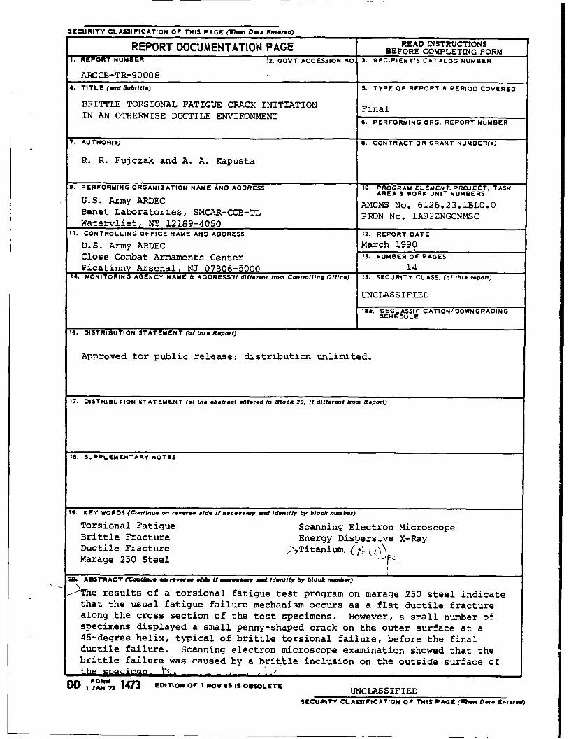
SA R ACT e - rm lei o f s eeread Identify by block number)
-The results of a torsional fatigue test program on marage 250 steel indicatethat the usual fatigue failure mechanism occurs as a flat ductile fracturealong the cross section of the test specimens. However, a small number ofspecimens displayed a small penny-shaped crack on the outer surface at a45-degree helix, typical of brittle torsional failure, before the finalductile failure. Scanning electron microscope examination showed that thebrittle failure was caused by a hr itle inclusion on the outside surface ofthe s .ecinn I-, , '- ,I
DD I "'I"I 1473 EDITiN OF I NOV65 IS OSILETE JAM C7S UNCLASSIFIEDSFCJIhTYl CLASSWICATIOm OF 'THIS PAGE (11be Data Entered)
TABLE OF CONTENTS
Page
ACKNOWLEDGEMENTS ........................................................... iii
INTRODUCTION ............................................................... 1
ANALYSIS ................................................................... 1
CONCLUSIONS ................................................................ 4
TABLES
I. CHEMICAL ANALYSIS OF MARAGE 250 STEEL ................................. 1
II. MECHANICAL PROPERTIES OF MARAGE 250 STEEL ............................. 2
LIST OF ILLUSTRATIONS
1. Torsional fatigue specimen cycled to failure--marage 250 steela. Side view of torsional fatigue test specimen after
fracture ........................................................... 6b. Fracture surface of test specimen, magnification 3x ................ 6
2a. Entire 45-degree crack, magnification lOx ............................. 7
2b. Fatigue crack initiation site, magnification lOOx ..................... 7
2c. Fatigue crack initiation site, magnification 500x ..................... 7
2d. Fatigue crack initiation site, magnification 1O,O00x .................. 7
3a. Imbedded particle at initiation site, magnification2,OOOx ................................................................ 8
3b. Imbedded particle at initiation site, magnification5,000x ................................................................ 8
3c. Energy dispersive x-ray analysis of particle richin titanium ........................................................... 8
3d. Energy dispersive x-ray analysis of adjacent matrixlow in titanium ....................................................... 8
4. Particle at sample surface, magnification 4,000x ...................... 9
5a. Fracture surface at fatigue crack origin, magnification4,000x ................................................................ 10
5b. Fracture surface, position b, magnification 1O,O00x ................... 10
Page
5c. Fracture surface, position c, magnification 10,000x .................. 10
5d. Fracture surface, position d, magnification 10,000x ................... 11
5e. Fracture surface, position e, magnification 10,000x ................... 11
5f. Fracture surface, position f, magnification 10,000x ................... 11
ACKNOWLEDGEMENTS
The authors gratefully acknowledge the assistance of Ronald T. Abbott of
the Materials Engineering Branch for testing the specimens in the tor-
sional fatigue testing program; Mark Fleszar and co-workers of the Advanced
Technology Branch for the chemical analysis; and from the Physical Sciences
Branch, Charles Nolan for supervision of the mechanical testing program and
Christopher Rickard for the metallography work.
Aaession For
NTIS GRA&IDTIC TAB 0Unannounced 0Just1ifictio.
ByDistributioe,
Availability Codes
val fland/or
Dist Speol.
I iii
INTRODUCTION
A torsional fatigue test program was designed to generate torsional fatigue
data over a wide range of twist moments and fatigue life, using two different
steels for comparison: AISI 4150H and marage 250 steel. A comparison of these
results will be presented in another report. In this report we discuss a phe-
ncmenon that occurred with a small number of specimens of marage 250 during
testing. Approximately 60 specimens were tested to failure in torsional
fatigue, and most of them failed in the characteristic manner of ductile tor-
sional failure--a flat fracture parallel to the twisting plane and normal to the
specimen longitudinal axis. However, a few specimens indicated brittle fatigue
crack initiation.
ANALYSIS
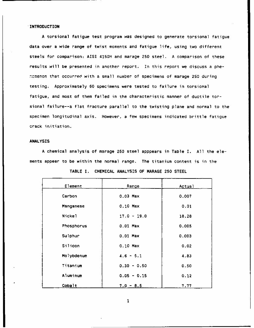
A chemical analysis of marage 250 steel apppears in Table I. All the ele-
ments appear to be within the normal range. The titanium content is in the
TABLE I. CHEMICAL ANALYSIS OF MARAGE 250 STEEL
Element Range Actual
Carbon 0.03 Max 0.007
Manganese 0.10 Max 0.01
Nickel 17.0 - 19.0 18.28
Phosphorus 0.01 Max 0.005
Sulphur 0.01 Max 0.003
Silicon 0.10 Max 0.02
Molybdenum 4.6 - 5.1 4.83
Titanium 0.30 - 0.50 0.50
Aluminum 0.05 - 0.15 0.12
Cobalt 7.0 - 8.5 7.77
1
upper level of the normal range, 0.50 percent actual level of the 0.30 to 0.50
percent expected range. The importance of this value is discussed later in this
report.
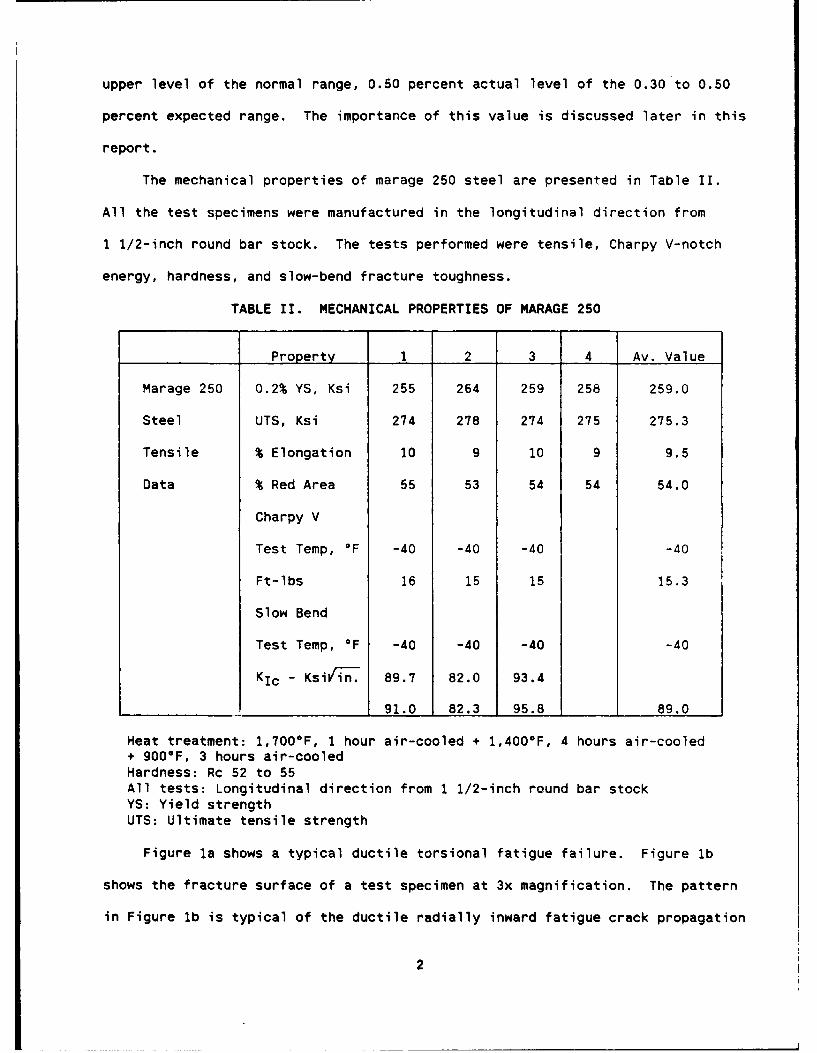
The mechanical properties of marage 250 steel are presented in Table II.
All the test specimens were manufactured in the longitudinal direction from
1 1/2-inch round bar stock. The tests performed were tensile, Charpy V-notch
energy, hardness, and slow-bend fracture toughness.
TABLE II. MECHANICAL PROPERTIES OF MARAGE 250
Property 1 2 3 4 Av. Value
Marage 250 0.2% YS, Ksi 255 264 259 258 259.0
Steel UTS, Ksi 274 278 274 275 275.3
Tensile % Elongation 10 9 10 9 9.5
Data % Red Area 55 53 54 54 54.0
Charpy V
Test Temp, OF -40 -40 -40 -40
Ft-lbs 16 15 15 15.3
Slow Bend
Test Temp, OF -40 -40 -40 -40
KIc - Ksiin. 89.7 82.0 93.4
91.0 82.3 95.8 89.0
Heat treatment: 1,700°F, 1 hour air-cooled + 1,4000F, 4 hours air-cooled+ 900°F, 3 hours air-cooledHardness: Rc 52 to 55All tests: Longitudinal direction from 1 1/2-inch round bar stockYS: Yield strengthUTS: Ultimate tensile strength
Figure la shows a typical ductile torsional fatigue failure. Figure lb
shows the fracture surface of a test specimen at 3x magnification. The pattern
in Figure lb is typical of the ductile radially inward fatigue crack propagation
2
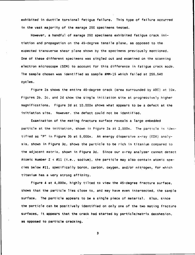
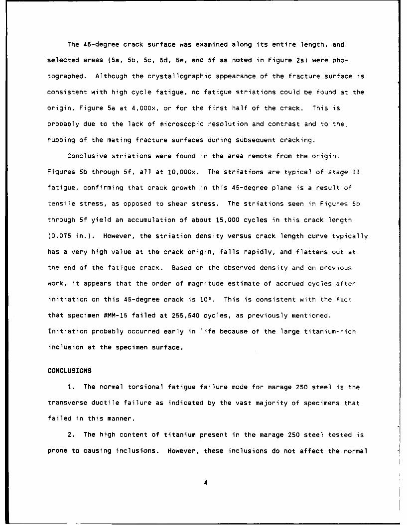
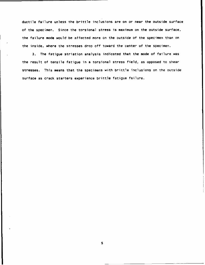
exhibited in ductile torsional fatigue failure. This type of failure occurred
in the vast majority of the marage 250 specimens tested.
However, a handful of marage 250 specimens exhibited fatigue crack ini-
tiation and propagation on the 45-degree tensile plane, as opposed to the
expected transverse shear plane shown by the specimens previously mentioned.
One of these different specimens was singled out and examined on the scanning
electron microscope (SEM) to account for this difference in fatigue crack mode.
The sample chosen was identified as sample #MM-15 which failed at 255,540
cycles.
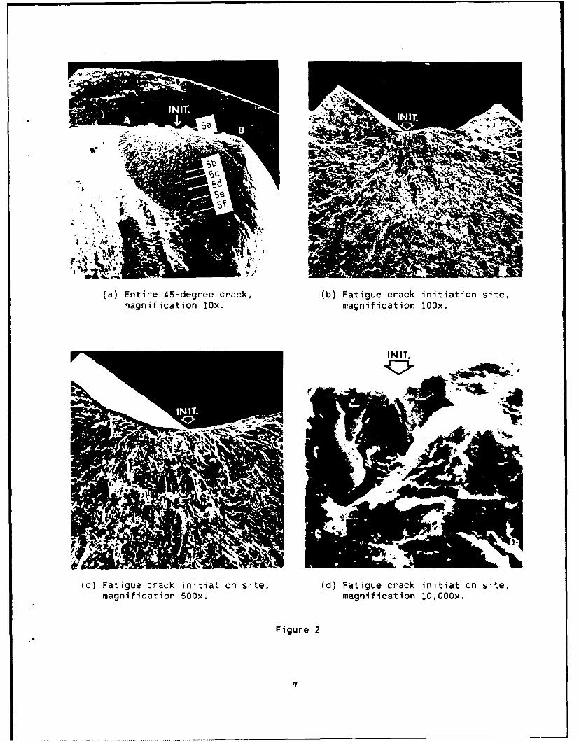
Figure 2a shows the entire 45-degree crack (area surrounded by ABC) at lOx.
Figures 2b, 2c, and 2d show the single initiation site at progressively higher
magnifications. Figure 2d at 1O,O00x shows what appears to be a defect at the
initiation site. However, the defect could not be identified.
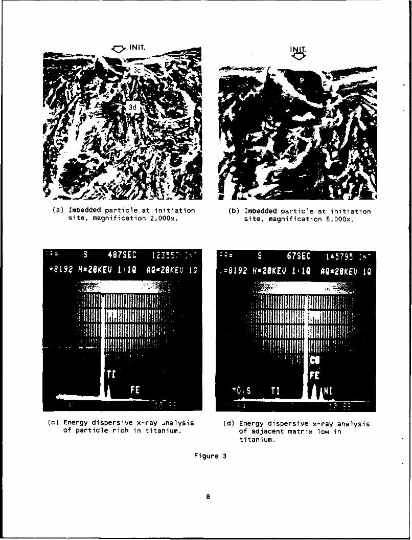
Examination of the mating fracture surface reveals a large embedded
particle at the initiation, shown in Figure 3a at 2,000x. The particle is iden-
tified as "P" in Figure 3b at 5,000x. An energy dispersive x-ray (EDX) analy-
sis, shown in Figure 3c, shows the particle to be rich in titanium compared to
the adjacent matrix, shown in Figure 3d. Since our x-ray analyzer cannot detect
Atomic Number Z < #11 (i.e., sodium), the particle may also contain atomic spe-
cies below #11, specifically boron, carbon, oxygen, and/or nitrogen, for which
titanium has a very strong affinity.
Figure 4 at 4,000x, highly tilted to view the 45-degree fracture surface,
shows that the particle lies close to, and may have even intersected, the sample
surface. The particle appears to be a single piece of material. Also, since
the particle can be positively identified on only one of the two mating fracture
surfaces, it appears that the crack had started by particle/matrix decohesion,
as opposed to particle cracking.
3
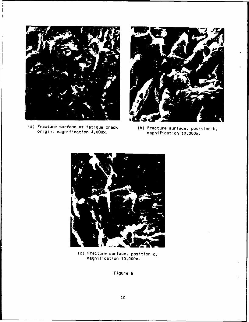
The 45-degree crack surface was examined along its entire length, and
selected areas (Sa, 5b, 5c, 5d, 5e, and 5f as noted in Figure 2a) were pho-
tographed. Although the crystallographic appearance of the fracture surface is
consistent with high cycle fatigue, no fatigue striations could be found at the
origin, Figure 5a at 4,000x, or for the first half of the crack. This is
probably due to the lack of microscopic resolution and contrast and to the.
rubbing of the mating fracture surfaces during subsequent cracking.
Conclusive striations were found in the area remote from the origin,
Figures 5b through 5f, all at 1O,O00x. The striations are typical of stage II
fatigue, confirming that crack growth in this 45-degree plane is a result of
tensile stress, as opposed to shear stress. The striations seen in Figures 5b
through 5f yield an accumulation of about 15,000 cycles in this crack length
(0.075 in.). However, the striation density versus crack length curve typically
has a very high value at the crack origin, falls rapidly, and flattens out at
the end of the fatigue crack. Based on the observed density and on orevious
work, it appears that the order of magnitude estimate of accrued cycles after
initiation on this 45-degree crack is 105. This is consistent with the fact
that specimen #MM-15 failed at 255,540 cycles, as previously mentioned.
Initiation probably occurred early in life because of the large titanium-rich
inclusion at the specimen surface.
CONCLUSIONS
1. The normal torsional fatigue failure mode for marage 250 steel is the
transverse ductile failure as indicated by the vast majority of specimens that
failed in this manner.
2. The high content of titanium present in the marage 250 steel tested is
prone to causing inclusions. However, these inclusions do not affect the normal
4
ductile failure unless the brittle inclusions are on or near the outside surface
of the specimen. Since the torsional stress is maximum on the outside surface,
the failure mode would be affected more on the outside of the specimen than on
the inside, where the stresses drop off toward the center of the specimen.
3. The fatigue striation analysis indicated that the mode of failure was
the result of tensile fatigue in a torsional stress field, as opposed to shear
stresses. This means that the specimens with brittle inclusions on the outside
surface as crack starters experience brittle fatigue failure.
5
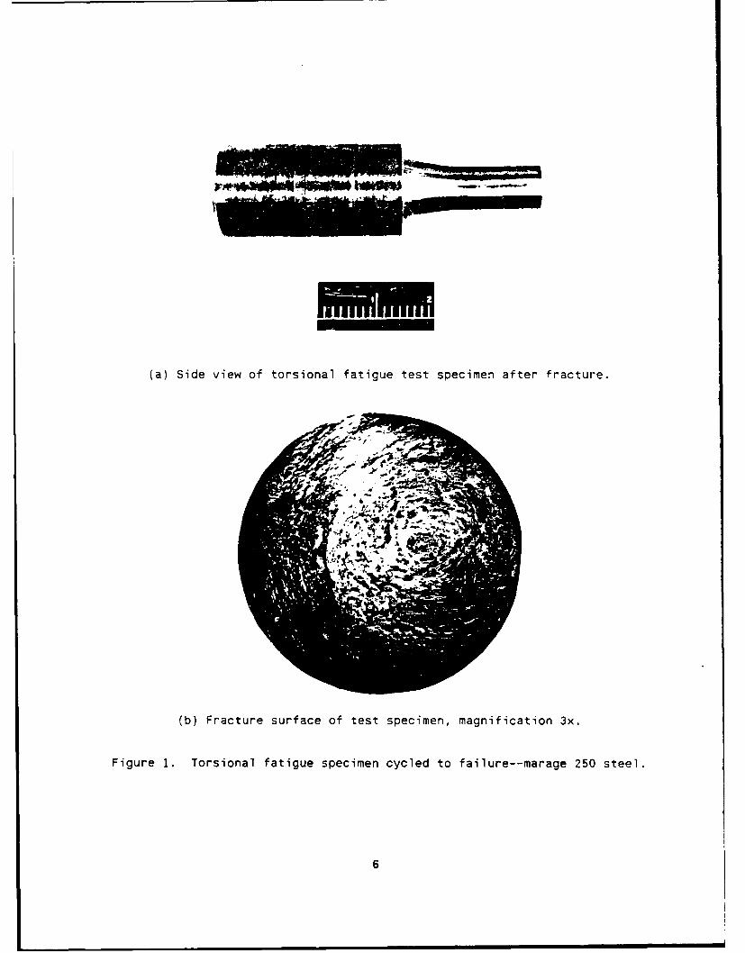
(a) Side view of torsional fatigue test specimen after fracture.
(b) Fracture surface of test specimen, magnification 3x.
Figure 1. Torsional fatigue specimen cycled to failure--marage 250 steel.
6
~S1
(a) Entire 45-degree crack, (b) Fatigue crack initiation site,magnification lox. magnification 100x.
~INIT.
(c) Fatigue crack initiation site, (d) Fatigue crack initiation site,magnification 500x. magnification lO,O00x.
Figure 2
7
IINIT.
(a) Imbedded particle at initiation (b) Imbedded particle at initiationsite, magnification 2,000x. site, magnification 5,000x.
=89 s8E 1 1 A92OE 10 =89 HE8E ItO A92OE 1
(c) Energy dispersive x-ray ,inalysis (d) Energy dispersive x-ray analysisof particle rich in titanium. of adjacent matrix low in
titanium.
Figure 3
8
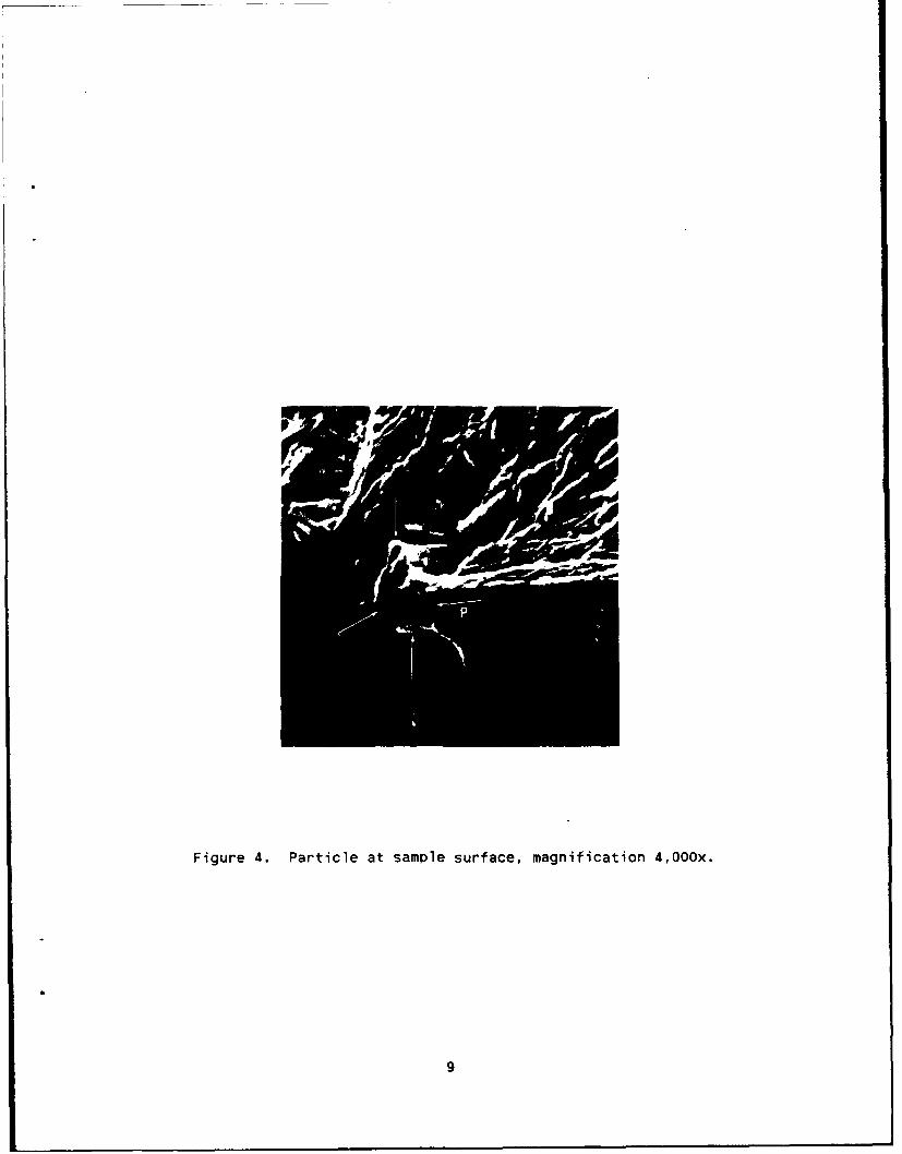
Figure 4. Particle at sample surface, magnification 4,000x.
9
(a) Fracture surface at fatigue crack (b) Fracture surface, position b,origin, magnification 4,000x. magnification 10,O00x.
(c) Fracture surface, position c,magnification 10,O00ox.
Figure 5
10
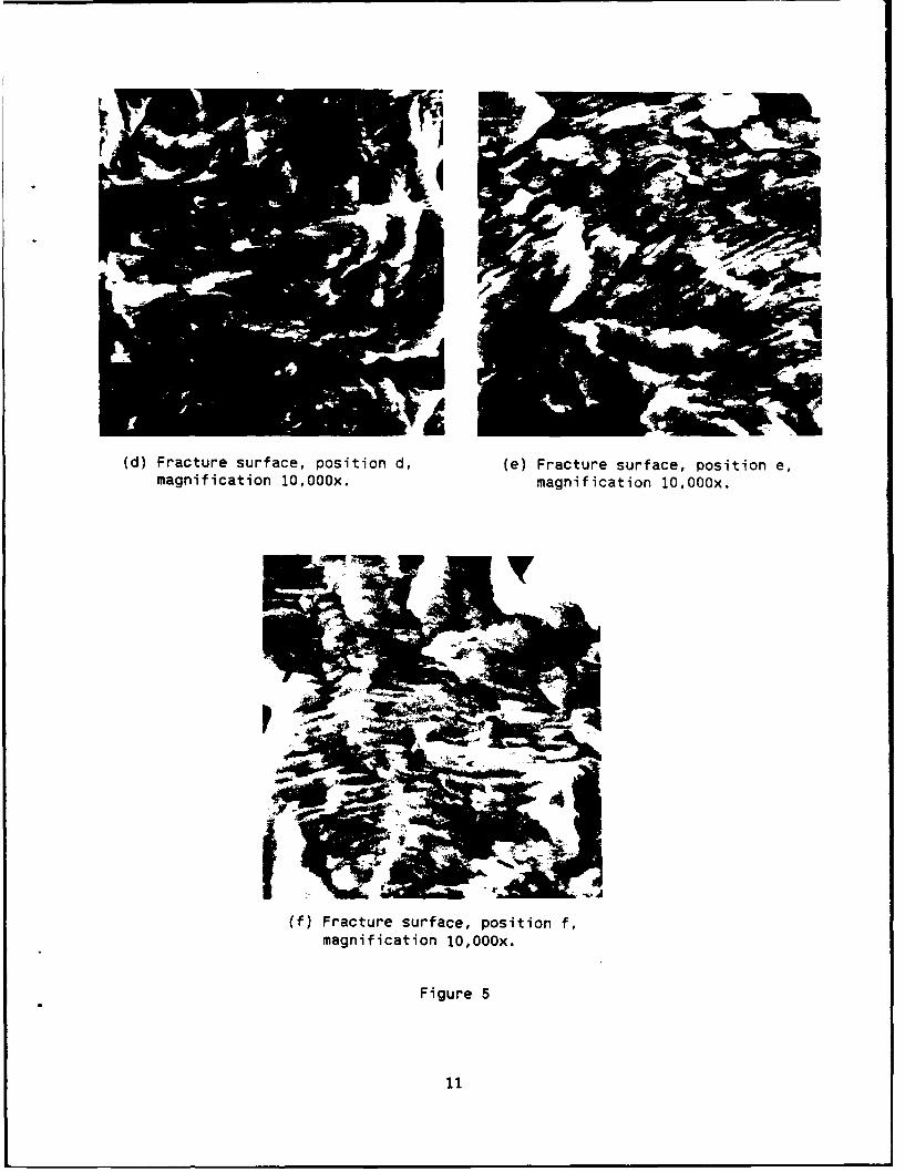
(d) Fracture surface, position d, (e) Fracture surface, position e,magnification 10,O00x. magnification 10,O00ox.
(f) Fracture surface, position f,magnification 10,O00ox.
Figure 5
11
TECHNICAL REPORT INTERNAL DISTRIBUTION LIST
NO. OFCOPIES
CHIEF, DEVELOPMENT ENGINEERING DIVISIONATTN: SMCAR-CCB-D
1-DA 1-DC 1-DM 1-DP 1-DR 1-DS (SYSTEMS) 1
CHIEF, ENGINEERING SUPPORT DIVISIONATTN: SMCAR-CCB-S
1-SE 1
CHIEF, RESEARCH DIVISIONATTN: SMCAR-CCB-R
2-RA 1-RM 1-RP 1-RT 1
TECHNICAL LIBRARY 5
ATTN: SMCAR-CCB-TL
TECHNICAL PUBLICATIONS & EDITING SECTION 3ATTN: SMCAR-CCB-TL
DIRECTOR, OPERATIONS DIRECTORATE 1ATTN: SMCWV-OD
DIRECTOR, PROCUREMENT DIRECTORATE 1ATTN: SMCWV-PP
DIRECTOR, PRODUCT ASSURANCE DIRECTORATE IATTN: SMCWV-QA
NOTE: PLEASE NOTIFY DIRECTOR, BENET LABORATORIES, ATTN: SMCAR-CCB-TL, OFANY ADDRESS CHANGES.
TECHNICAL REPORT EXTERNAL DISTRIBUTION LIST
NO. OF NO. OFCOPIES COPIES
ASST SEC OF THE ARMY COMMANDERRESEARCH AND DEVELOPMENT ROCK ISLAND ARSENALATTN: DEPT FOR SCI AND TECH 1 ATTN: SMCRI-ENMTHE PENTAGON ROCK ISLAND, IL 61299-5000WASHINGTON, D.C. 20310-0103
DIRECTORADMINISTRATOR US ARMY INDUSTRIAL BASE ENGR ACTVDEFENSE TECHNICAL INFO CENTER ATTN: AMXIB-PATTN: DTIC-FDAC 12 ROCK ISLAND, IL 61299-7260CAMERON STATIONALEXANDRIA, VA 22304-6145 COMMANDER
US ARMY TANK-AUTMV R&D COMMANDCOMMANDER ATTN: ANSTA-DDL (TECH LIB)US ARMY ARDEC WARREN, MI 48397-5000ATTN: SMCAR-AEE 1
SMCAR-AES, BLDG. 321 1 COMMANDERSMCAR-AET-O, BLDG. 351N 1 US MILITARY ACADEMYSMCAR-CC 1 ATTN: DEPARTMENT OF MECHANICSSMCAR-CCP-A 1 WEST POINT, NY 10996-1792SMCAR-FSA 1SMCAR-FSM-E 1 US ARMY MISSILE COMMANDSMCAR-FSS-D, BLDG. 94 1 REDSTONE SCIENTIFIC INFO CTR 2SMCAR-IMI-I (STINFO) BLDG. 59 2 ATTN: DOCUMENTS SECT, BLDG. 4484
PICATINNY ARSENAL, NJ 07806-5000 REDSTONE ARSENAL, AL 35898-5241
DIRECTOR COMMANDERUS ARMY BALLISTIC RESEARCH LABORATORY US ARMY FGN SCIENCE AND TECH CTRATTN: SLCBR-DD-T, BLDG. 305 1 ATTN: DRXST-SDABERDEEN PROVING GROUND, MD 21005-5066 220 7TH STREET, N.E.
CHARLOTTESVILLE, VA 22901DIRECTORUS ARMY MATERIEL SYSTEMS ANALYSIS ACTV COMMANDERATTN: AMXSY-MP 1 US ARMY LABCOMABERDEEN PROVING GROUND, MD 21005-5071 MATERIALS TECHNOLOGY LAB
ATTN: SLCMT-IML (TECH LIB) 2COMMANDER WATERTOWN, MA 02172-0001HQ, AMCCOMATTN: AMSMC-IMP-L 1ROCK ISLAND, IL 61299-6000
NOTE: PLEASE NOTIFY COMMANDER, ARMAMENT RESEARCH, DEVELOPMENT, AND ENGINEERINGCENTER, US ARMY AMCCOM, ATTN: BENET LABORATORIES, SMCAR-CCB-TL,WATERVLIET, NY 12189-4050, OF ANY ADDRESS CHANGES.

TECHNICAL REPORT EXTERNAL DISTRIBUTION LIST (CONT'D)
NO. OF NO. OFCOPIES COPIES
COMMANDER COMMANDERUS ARMY LABCOM, ISA AIR FORCE ARMAMENT LABORATORYATTN: SLCIS-IM-TL 1 ATTN: AFATL/MN2800 POWDER MILL ROAD EGLIN AFB, FL 32542-5434ADELPHI, MD 20783-1145
COMMANDERCOMMANDER AIR FORCE ARMAMENT LABORATORYUS ARMY RESEARCH OFFICE ATTN: AFATL/MNFATTN: CHIEF, IPO 1 EGLIN AFB, FL 32542-5434P.O. BOX 12211RESEARCH TRIANGLE PARK, NC 27709-2211 METALS AND CERAMICS INFO CTR
BATTELLE COLUMBUS DIVISIONDIRECTOR 505 KING AVENUEUS NAVAL RESEARCH LAB COLUMBUS, OH 43201-2693ATTN: MATERIALS SCI & TECH DIVISION 1
CODE 26-27 (DOC LIB) 1WASHINGTON, D.C. 20375
NOTE: PLEASE NOTIFY COMMANDER, ARMAMENT RESEARCH, DEVELOPMENT, AND ENGINEERINGCENTER, US ARMY AMCCOM, ATTN: BENET LABORATORIES, SMCAR-CCB-TL,WATERVLIET, NY 12189-4050, OF ANY ADDRESS CHANGES.