ada mp-1 mod4 mark iiadadepot.com/mods/ada_mp-1_mod4_mark_ii.pdfmp-1 mod4 mark ii loading chart...
TRANSCRIPT

ADA MP-1 MOD4 Mark II
G. Philippe R. Metzger
R. Metzger 4/2004
© 2004 BagBout Electronics
Permission denied for re-posting except by explicit permission from

MP-1 MOD4 Mark II Schematic

MP-1 MOD4 Mark II Loading Chart
Resistors: Stock
MOD4
Capacitors: Stock
MOD4
R13 > 750k R14 > 270k R15 > 1.1k R18 > 1M R19 > 510k R20 > 750k R21 > 270k R22 > 16k R24 > 4.7k R25 > 16k R26 > 3.9k
470k 470k 10k NONE 470k 470k 470k 2.7k NONE 2.7k NONE
C3 > 0.0068µF/200V C4 > 100pF/1kV C5 > 0.015µF/200V C6 > 33µF/50V (Radial) C7 > 33µF/50V (Radial) C9 > 0.0068µF/200V C10 > 0.0068µF/200V C11 > 100pF/1kV C12 > 33µF/50V (Radial) C13 > 33µF/50V (Radial) C14 > 2700pF (0.0027µF) 100V C15 > 0.01µF/100V C16 > 33µF/50V (Radial)
0.022µF/200V Min 620pF/200V Min 0.022µF/200V Min 1µF/25V Min (Radial) NONE 0.022µF/200V Min 0.022µF/200V Min 620pF/200V Min 0.47µF/25V Min (Radial) Jumper NONE NONE 0.47µF/25V Min (Radial)

MP-1 MOD4 Mark II Parts List All replacement components can be obtained from Mouser Electronics http://www.mouser.com Please Note: The parts listed here are the fully tested and recommended components. As always, you can safely substitute components with different composition, tolerance, etc, just be sure the part meets the minimum voltage requirement. Quantity Value/Description Mouser Part # 5 470k 1/2W 1% Metal Film Resistor 273-470k 1 10k 1/4W 1% Metal Film Resistor 271-10k 2 2.7k 1/4W 1% Metal Film Resistor 271-2.7k 4 0.022µF 400V “Orange Drop” Polypropylene Film Capacitor 75-715P400V0.022 2 620pF 300V Silver Mica Capacitor 5982-15-300V620 2 0.47µF 100V Radial Electrolytic Capacitor 140-HTRL100V.47 1 1µF 100V Radial Electrolytic Capacitor 140-HTRL100V1.0
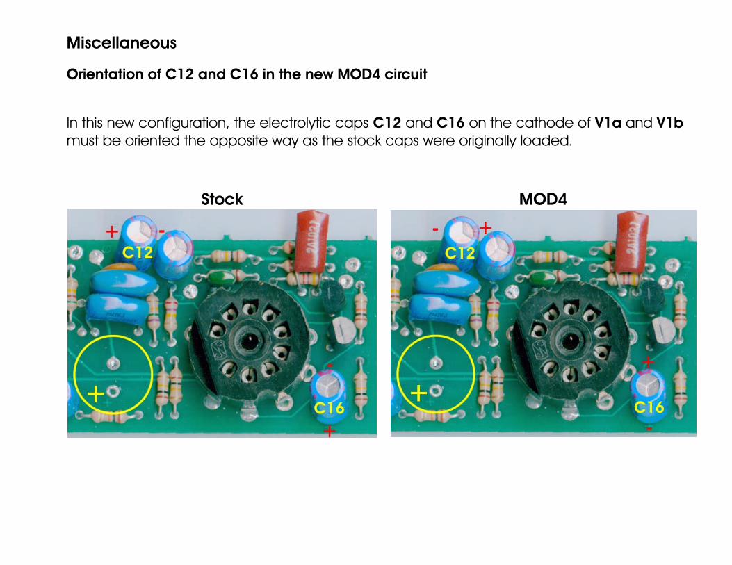
Miscellaneous Orientation of C12 and C16 in the new MOD4 circuit In this new configuration, the electrolytic caps C12 and C16 on the cathode of V1a and V1b must be oriented the opposite way as the stock caps were originally loaded.
Stock MOD4