adaptations to a marine climate, salt and water owez r 111...
TRANSCRIPT
KEMA Nederland B.V. Utrechtseweg 310, 6812 AR Arnhem P.O. Box 9035, 6800 ET Arnhem The Netherlands T +31 26 3 56 91 11 F +31 26 3 89 24 77 [email protected] www.kema.com Registered Arnhem 09080262
50863231-TOS/NRI 10-2242 Adaptations to a marine climate, salt and water OWEZ_R_111_20101020 Results corrosion inspections Offshore wind farm Egmond aan Zee, 2007-2009
Arnhem, October 20, 2010
Author M.P. de Jong
By order of Noordzeewind
© KEMA Nederland B.V., Arnhem, the Netherlands. All rights reserved. It is prohibited to change any and all versions of this document in any manner whatsoever, including but not limited todividing it into parts. In case of a conflict between the electronic version (e.g. PDF file) and the original paper version provided by KEMA, the latter will prevail. KEMA Nederland B.V. and/or its associated companies disclaim liability for any direct, indirect, consequential orincidental damages that may result from the use of the information or data, or from the inability to use the information ordata contained in this document. The contents of this report may only be transmitted to third parties in its entirety and provided with the copyright notice,prohibition to change, electronic versions’ validity notice and disclaimer.
-3- 50863231-TOS/NRI 10-2242 CONTENTS page
SUMMARY...............................................................................................................................6
1 General ...................................................................................................................7
2 Location of the OWEZ ............................................................................................7
3 Codes and standards applicable to the offshore wind park ....................................8 3.1 Classification of corrosion environments ................................................................8 3.2 Corrosion protection standards...............................................................................9 3.3 Paintings and coatings............................................................................................9 3.3.1 The meteorological mast ......................................................................................10
4 Scheduled O&M inspections.................................................................................11 4.1 Scope....................................................................................................................11 4.1.1 WTG foundations outline details...........................................................................12 4.1.2 Access for inspections and repairs .......................................................................13 4.2 Inspections............................................................................................................14 4.2.1 Above water inspections.......................................................................................14 4.2.2 Below water inspections .......................................................................................15 4.2.3 Inspection cathodic protection ..............................................................................17 4.3 Repair procedures ................................................................................................17 4.3.1 Physical damages repairs.....................................................................................17 4.3.2 Coating repairs and touch-up ...............................................................................18
5 Monitoring program inspections............................................................................18 5.1 Above water inspections.......................................................................................19 5.1.1 Inspection by boat.................................................................................................20 5.1.2 Access arrangement.............................................................................................20 5.1.3 Intermediate ladder...............................................................................................20 5.1.4 Intermediate platform............................................................................................21 5.1.5 Upper access ladder.............................................................................................21 5.1.6 Access platform ....................................................................................................21 5.1.7 Interior, bulkhead deck .........................................................................................23
6 Below water inspections .......................................................................................23 6.1.1 Inspection by divers or ROV.................................................................................25
-4- 50863231-TOS/NRI 10-2242 7 Corrosion inspection tower and nacelle................................................................25 7.1.1 Internal tower inspection.......................................................................................27 7.1.2 Nacelle inspection.................................................................................................27 7.2 Periodic monitoring ...............................................................................................29 7.2.1 General .................................................................................................................29 7.2.2 Scope of periodic monitoring ................................................................................29
8 Inspection results wind turbines............................................................................30 8.1 The O&M inspections ...........................................................................................30 8.1.1 Inspections 2007...................................................................................................31 8.1.2 Inspections 2008...................................................................................................34 8.1.3 Inspections 2009...................................................................................................37 8.2 Monitoring program inspections............................................................................41 8.2.1 Inspections 2008...................................................................................................41 8.2.2 Inspections 2009...................................................................................................42 8.2.3 Grating of the access arrangement ......................................................................42 8.2.4 Below water inspections .......................................................................................43 8.2.5 Corrosion inspection tower and nacelle................................................................43 8.2.6 Nacelle inspection.................................................................................................45
9 Inspection results meteorological mast.................................................................48 9.1 Below water inspections .......................................................................................48 9.2 Above water inspections.......................................................................................48
10 Discussion ............................................................................................................49 10.1 The condition of the wind turbines ........................................................................49 10.1.1 Conditions of monopiles below water ...................................................................49 10.1.2 Conditions wind turbines above water ..................................................................49 10.2 The condition of the meteo mast ..........................................................................50 10.2.1 The influence of bird droppings and pancreatin on coating degradation ..............51 10.2.2 Coating system of the meteo mast and wind turbine............................................52 10.3 Bio fouling versus corrosion..................................................................................52 10.4 Codes and standards............................................................................................53
11 Conclusions ..........................................................................................................53
12 Recommendations................................................................................................54
REFERENCES.......................................................................................................................55

-5- 50863231-TOS/NRI 10-2242 Appendix I Reference List corrosion protection, coatings & paintings..............................57
Appendix II O&M coating inspection..................................................................................59
Appendix III O&M damages and bolts inspection ...............................................................60
Appendix IV Coating surface treatment sheet.....................................................................61
Appendix V Examples of reported anomalies ....................................................................62
Appendix VI Inspections 2008.............................................................................................65
Appendix VII Inspections 2009.............................................................................................73
-6- 50863231-TOS/NRI 10-2242 SUMMARY NoordzeeWind is a joint venture between utility company Nuon and oil company Shell and has been set up specifically for the development, construction and operation of the Offshore Wind farm Egmond aan Zee (OWEZ). As part of the OWEZ project NoordzeeWind will carry out an extensive monitoring program. The contents of the monitoring program are about generating data and knowledge. The aim of task 1.1.1 – salt and spray – of the monitoring program is to gain knowledge on corrosion of the wind turbines offshore. To achieve this goal, more detailed inspections were carried out on top of the inspections that are part of the normal day to day operation of the wind farm. Detailed inspections were carried out by Adviescentrum Civiel & Corrosiebescherming (ACC) on behalf of KEMA in 2008 and by KEMA itself in 2009. This report presents the inspection procedures, results of all inspections and an analyses of all provided inspection data of inspections carried out in 2007, 2008 and 2009 as part of the normal operations and maintenance of the entire Offshore Wind farm Egmond aan Zee.1 Up to now, the O&M inspections combined with the monitoring program inspections give a clear indication of the effectiveness of the selected corrosion protection. Since there are no serious corrosion problems, the corrosion protection of the wind turbines is effective. However, there are damages and anomalies reported which are mostly related to mechanical impact or quality of coating application and/or repair. The coating systems need to be checked and may require some minor repair on a regular (yearly) base. The repeating damage or anomaly is related either to loose/break hilty’s or bolts, or to their corrosion. Therefore, the attention for these items will be part on the Operation & Maintenance plan. Acknowledgement The Offshore Wind farm Egmond aan Zee has a subsidy of the Ministry of Economic Affairs under the CO2 Reduction Scheme of the Netherlands.
1 Prior to publication, this report has been reviewed by Shell and Nuon experts.

-7- 50863231-TOS/NRI 10-2242 1 GENERAL NoordzeeWind is a joint venture between utility company Nuon and oil company Shell and has been set up specifically for the development, construction and operation of the Offshore Wind farm Egmond aan Zee (OWEZ). As part of the OWEZ project, NoordzeeWind will carry out a monitoring program with the objective to generate operational data and knowledge. The aim of task 1.1.1 – salt and spray – of the monitoring program is to gain knowledge on corrosion of the offshore wind turbines. This report presents the results of a detailed inspection carried out by COT on behalf of KEMA in 2008. An inspection conducted by KEMA in 2009 and an analysis of all provided inspection data of inspections of the entire Offshore Wind farm Egmond aan Zee were carried out in 2007 and 2008.
2 LOCATION OF THE OWEZ The Offshore Wind farm Egmond aan Zee (OWEZ) is located 10-18 kilometers offshore from the Dutch coastal village Egmond aan Zee. Figure 1 shows the lay out of the wind farm (the boundaries of the concession area are shown as a solid line). The individual wind turbines in the park are shown in figure 1 as triangles. The minimum distance between two wind turbines is 640 meters.

-8- 50863231-TOS/NRI 10-2242
Figure 1 Boundary of the wind farm and positions of the wind turbines
3 CODES AND STANDARDS APPLICABLE TO THE OFFSHORE WIND PARK
3.1 Classification of corrosion environments According to their corrosivity, the environments which cause corrosion can be classified in different categories. The classification is based on standard ISO 9223:1992 Corrosion of metals and alloys -- Corrosivity of atmospheres -- Classification. It categorizes environments on the basis of wet time, as well as sulphur dioxide and chloride contents. The standard ISO 9224 Corrosion of metals and alloys -- Corrosivity of atmospheres -- Guiding values for the corrosivity categories gives the corrosion rates of steel, zinc, copper and aluminium in the first five years. In the two following standards, the corrosivity categories are determined by the loads imposed by the atmosphere and through immersion: − EN ISO 12944-2:
Paints and varnishes - Corrosion protection of steel structures by protective paint systems - Part 2: Classification of environments
− ISO 14713: Protection against corrosion of iron and steel in structures – Zinc and aluminium coatings – Guidelines.
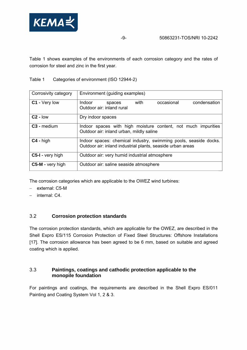
-9- 50863231-TOS/NRI 10-2242 Table 1 shows examples of the environments of each corrosion category and the rates of corrosion for steel and zinc in the first year. Table 1 Categories of environment (ISO 12944-2) Corrosivity category Environment (guiding examples)
C1 - Very low Indoor spaces with occasional condensationOutdoor air: inland rural
C2 - low Dry indoor spaces
C3 - medium Indoor spaces with high moisture content, not much impuritiesOutdoor air: inland urban, mildly saline
C4 - high Indoor spaces: chemical industry, swimming pools, seaside docks.Outdoor air: inland industrial plants, seaside urban areas
C5-I - very high Outdoor air: very humid industrial atmosphere
C5-M - very high Outdoor air: saline seaside atmosphere
The corrosion categories which are applicable to the OWEZ wind turbines: − external: C5-M − internal: C4. 3.2 Corrosion protection standards The corrosion protection standards, which are applicable for the OWEZ, are described in the Shell Expro ES/115 Corrosion Protection of Fixed Steel Structures: Offshore Installations [17]. The corrosion allowance has been agreed to be 6 mm, based on suitable and agreed coating which is applied. 3.3 Paintings, coatings and cathodic protection applicable to the
monopile foundation For paintings and coatings, the requirements are described in the Shell Expro ES/011 Painting and Coating System Vol 1, 2 & 3.

-10- 50863231-TOS/NRI 10-2242 Note 1: The requirement for polychloropropene coating on the inside of the J-tubes is changed. A suitable cable protection similar to 'Uraduct' or 'Omtec' is used in the area near the monopile beyond the J-tube mouth and the J-tube is sealed at the bottom [17]. Note 2: NZW advised that for the North See usually 500 μm coating thickness is applied. Therefore, NZW stressed the importance of surface preparation and structure quality control throughout the coating appliance. BCE agreed to involve NZW at the early stage when defining the coating for the transition piece and to forward coating procedures as soon as drafts will be available [17]. Note 3: NZW agreed to delete the requirement for a constant cathodic protection (CP) monitoring system subject to an increased inspection regime, allthough their experience to measure potential was bad if there is no direct contact to the anode. It was agreed that a baseline survey (ROV stabbing the anodes and inspecting them visually) would be carried out as well as identical follow-up surveys every two years. This regime would be reviewed based on the results after 5 years [17] The coating and painting procedure, which is applicable to the wind turbines, is applied by Bladt and described in the Bladt Coating manual [16]. Appendix I presents a reference list with respect to specification, standards and codes applicable to the corrosion protection system including materials, coatings and paintings. 3.3.1 The meteorological mast The meteorological mast (Metmast) was installed to facilitate several measurements required for the NSW-MEP. The Metmast was erected already in 2003 prior to the installation of the wind turbines. Several construction details of the Metmast and the applied coatings differ from the wind turbines.
-11- 50863231-TOS/NRI 10-2242 Table 2 shows the details of the applied coatings and corrosion protection [18].

-12- 50863231-TOS/NRI 10-2242 Table 2 Applied coatings and corrosion protection of the meteorological mast
Spray zone +12m u/i +36m. (N.A.) Splash zone -4,3m u/i 12m Hand railing: − Hot dip galvanized − 1st layer coating; Barapox Universal HB. Dft = 60 – 120 micron − 2nd layer coating; Polycoat HS. Dft = 80 – 120 micron
Structural steel: − Coating CeRam Cote54. Dft 300 microns.
Instrument booms, ladders and grating: − Hot dip galvanized
Ladders and hand railing: − Hot dip galvanized − Coating CeRam Cote54. Dft 250 microns.
Grating: − Hot dip galvanized
4 SCHEDULED O&M INSPECTIONS 4.1 Scope The services for inspection and maintenance of the Wind Turbine foundations include above and under water inspections of the steel structure, coating systems, bolts, cathodic protection and scour protection. The services can be summarized as follows: − Yearly above water inspections
• 01 Physical damages • 02 Coating damages • 03 Loosened bolts
− Yearly under water inspections by divers • 04 Physical damages • 05 Coating damages • 06 Loosened bolts
− Bi-Yearly inspections by a corrosion engineer • 07 Potential readings
− Yearly survey-inspections • 08 Scour protection.
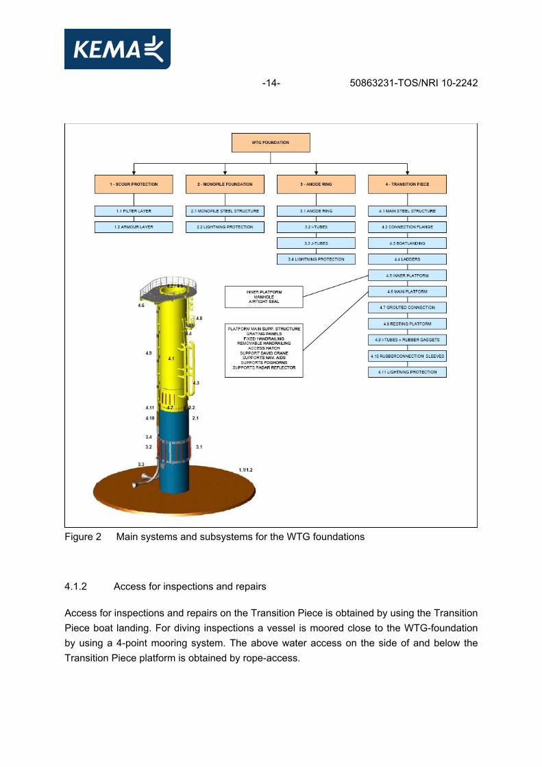
-13- 50863231-TOS/NRI 10-2242 The inspections and the related Acceptance Criteria are specified in the Inspection and Test Plans referred to as ITP’s (A1 - Inspection and Test Plans). The registration of the inspections and the required attachments are specified on the Request For Inspection forms or RFI’s (WTG Foundations outline details). If the inspected items do not meet the Acceptance Criteria, a Non Conformance Report is to be submitted [19] and repairs will be included in the scheduled maintenance [19]. 4.1.1 WTG foundations outline details The WTG foundations include a Monopile, a Transition Piece and an Anode Ring. At the top-end of the Transition Piece, a flange is welded. The WTG tower sections are bolted to the Transition Piece flange. The foundation is protected against erosion by scour protection which is positioned around the Monopile. The main systems and subsystems of the WTG foundations are summarized in figure 2.
-14- 50863231-TOS/NRI 10-2242
Figure 2 Main systems and subsystems for the WTG foundations
4.1.2 Access for inspections and repairs Access for inspections and repairs on the Transition Piece is obtained by using the Transition Piece boat landing. For diving inspections a vessel is moored close to the WTG-foundation by using a 4-point mooring system. The above water access on the side of and below the Transition Piece platform is obtained by rope-access.
-15- 50863231-TOS/NRI 10-2242 4.2 Inspection procedures Inspections will be carried out during the spring-summer season at favourable weather conditions (enabling the O&M engineer and/or his representatives to carry out high-quality inspections). Therefore, the weather forecasts shall be checked with a meteorological forecasting agent prior to offshore visits. Note that such conditions shall be limited to weather conditions with wave heights of Hs 1,2 m). 4.2.1 Above water inspections The above water inspections and the Acceptance Criteria are summarized in ITP-WP-MD-309.01, -309.02 and -309.03 (A1 - Inspection and Test Plans). The inspections include general check-up’s for physical damages, coating damages and untensioned bolts which will be separately explained below. The results of the inspections will be related to the BNEOE-WP-MD-309-RFI.01, 02 and 03 (A2 - Requests For Inspection) and will include the noted attachments (post installation surveys, daily progress reports, pictures of damages and painting test reports as per ISO4628/2-5). If items do not comply with the ITP-Acceptance Criteria, a non-conformance report will be issued (A3 - Non-Conformance Reports). On all WTG-foundations, yearly above water inspections will be carried out. Physical damages Physical damage inspections include all primary and secondary steel items. Upon sailing the WTG-foundation (and before transferring the crew onto the WTG-foundation), it has to be checked that no damage can be seen in particular on the I-tubes (for instance caused by floating containers). If serious damages to I-tubes are recognized, no further actions will be carried out before shutting down the wind turbine (according to BNEOE-WP-MD-309-RA01 to RA03 + RA07 (A4 - Risk Analyses O&M Civil). If the I-tubes have to be repaired, the authorization by the O&M engineer of cable system & HV equipment will be required. The inner platform of the Transition Piece includes a manhole cover. If a damage to the airtight seal is suspected, the seal will be replaced. According to BNEOE-WP-MD-309-RA01 to RA03 + RA07 (A4 - Risk Analyses O&M Civil), a potentially low O2 concentration can be expected when the manhole cover is opened (allowing air above the inner platform to mix with low-O2 air inside the Transition Piece). Therefore, sufficient time is used for ventilation (keep door WTG-tower opened). Operations shall not proceed with O2 levels below 21%, the O2-level within the confined area has to be tested (refer to attachment B10 – O2-level measurements for details on testing-device and also toxins shall be measured).
-16- 50863231-TOS/NRI 10-2242 The sections of the transition piece that cannot be reached by ladders are checked by sailing around the transition piece (with the crew tender). Rope access for inspections is only used if serious damages will be suspected (after visual checking from the crew tender). The required inspections are indicated in ITP BNEOE-WP-MD-309.01. Coating damages Based on the Acceptance Criteria, i.e. ISO4628/2-5, coating damages were checked. The International standard includes pictorial standards of rates, densities and seizes of various types of damages. Painting surfaces were checked for blistering, rusting, cracking and flaking. For details, please refer to attachment B2 – Coating references (ISO4628). Note: according to ISO4628/2-5, the major damages caused by boats and/or floating objects are beyond the acceptance criteria. The required inspections are indicated in ITP BNEOE-WP-MD-309.02. Untensioned bolts The Transition Piece includes various M12 bolted connections. All connections have to be checked visually. A random number of bolts have to be re-tensioned (at least 20% of all bolted connections) to check whether the bolts are still hand-tight. For details on bolted connections, please refer to attachment C2 - Spare Parts specifications and the design drawings 61-00-SD-1021, 1031, 1053, 1054 and 1082. The required inspections are indicated in ITP BNEOE-WP-MD-309.03. 4.2.2 Below water inspections The below water inspections and the Acceptance Criteria are summarized in ITP-WP-MD-309.04, -309.05 and -309.06 (A1 - Inspection and Test Plans). The below water inspections include checks for physical damages, coating damages and untensioned bolts. The results of the inspections will be related to BNEOE-WP-MD-309-RFI.04, 05 and 06 (A2 - Requests For Inspection) and will include the noted attachments (diving reports, diving records, diving logs, daily progress reports, working permits, underwater pictures / video of damages and approved anchor plans). If items do not comply with the ITP-Acceptance Criteria, a non-conformance report will be issued (A3 – Non-Conformance Reports).
-17- 50863231-TOS/NRI 10-2242 Physical damages Note: high-voltage power cables are carried by: − I-tubes which are mounted at the side of the transition piece − rubber connections between the I-tubes and J-tubes − J-tubes. All these items have to be treated with extreme caution. If serious damages to I-tubes are recognized, no further actions will be carried out before shutting down the wind turbine (according to BNEOE-WP-MD-309-RA04a to RA06a, A4 - Risk Analyses O&M Civil). If the I-tubes have to be repaired, authorisation by the O&M engineer of cable system & HV equipment will be required. The required inspections are indicated in ITP BNEOE-WP-MD-309.04. Coating damages Between the Mean Sea Level and the top of the Monopile (-5.5MSL), coating has been applied to all primary and secondary steel items of the Transition Piece. Coating inspections are carried out to recognize general visual coating damages. Note that marine-growth is not removed for coating-inspection purposes. The required inspections are indicated in ITP BNEOE-WP-MD-309.05. Untensioned bolts The anode-rings, i.e. the 120O ring-sections, are connected by M30 bolts. At the anode ring closure joint, these bolts have been tensioned under water after installation of the anode rings (in-situ bolted connections; refer to attachment C2 - Spare Parts specifications). When the inspections are carried out, the in-situ bolted connections will be checked by re-tensioning. The required inspections are indicated in ITP BNEOE-WP-MD-309.06.
-18- 50863231-TOS/NRI 10-2242 4.2.3 Inspection cathodic protection A corrosion engineer shall measure potential readings at 1m intervals between MSL=0m and the sea-bottom level. The monitoring is done by means of potential measurement (refer to attachment B3 - Corrosion measurements procedure for general details on the measurements). Concerning the first two years of the O&M phase, the measurements will be carried out based on a 100% basis, i.e. all 36 WTG-foundations. If the measured values stay constant, then the number of measurements can be re-evaluated and adjusted, when agreed with NZW. Potential measurements are carried out to verify the effectiveness of the cathodic protection system. The level of protection should stay above, i.e. more negative than, -800mV. If lower levels are measured, remedial measures will be proposed by the Designer. The required inspections are indicated in ITP BNEOE-WP-MD-309.07. 4.3 Repair procedures After and/or during the inspections (refer to Scope section to on page 5), repairs will be carried out. According to section A1 - Inspection and Test Plans, minor repairs, i.e. small damaged and/or items marked “I” on ITP’s, can be carried out directly without authorization. Major repairs (significant damages and/or items marked “H”, “N” and/or “P” on ITP’s as per section A1 - Inspection and Test Plans) must be carried out only if the Owner’s O&M representative, the Designer and/or the O&M engineer of cable system was/were asked for approval. The most common repairs are described in the following sections. For significant damages, separate repair procedures are installed by using the NCR (refer to attachment A3 – Non-Conformance Reports). 4.3.1 Physical damages repairs Physical damages include possible repair and replacement of primary/secondary steel structures, rubber sleeves, and gaskets and grating panels (refer to attachment C2 - Spare Parts specifications for details). In any case, all repairs which require on-site welding, cutting and grinding will be communicated to the Owner’s O&M representative, the Designer and the O&M engineer cable system. For the replacement and the repairs of grating panels, a shot hammer system will be used (refer to attachment C2 - Spare Parts specifications for details). If the shot-hammer system is used, operations below the platform level will be carried out without any workers and/or divers.
-19- 50863231-TOS/NRI 10-2242 As mentioned above, I-tubes and J-tubes carry live power cables. Repairs to these items (including connecting rubber gaskets and sleeves) are not to be carried out without consulting the O&M engineer cable system. 4.3.2 Coating repairs and touch-up Coating repairs have to be carried out related to the repair procedure (refer to attachment B1 - Paint repair procedure and equipment for details). The coating repair system includes “Hempadur Multi-Strength 45753” primer layers and a “Hempathane Topcoat 55210” topcoat. Paint repairs can be only carried out when the steel temperatures are at least 3 °C above the dew point temperature. In order to verify the criteria, i.e. steel temperature, ambient temperature and related dew point temperature, a suitable tool2 has to be used. Prior to coating repairs, oil and grease are to be removed by solvent cleaning (thinner). The area of interest must be cleaned of soluble salts, and afterwards, the damages will be mechanically cleaned by grinding according to St.3 (ISO8501-1). Before starting the paint repairs, grinding residues should be removed by using solvent cleaning. After the painting, the results will be tested by using a digital calibrated measurement tool according to ISO2178, ISO2808 and ISO1462 (Elcometer456 as per attachment B1 - Paint repair procedure and equipment for details).
5 MONITORING PROGRAM INSPECTIONS As part of the OWEZ monitoring program the corrosion inspections need to cover the complete wind turbine, whereas the normal day to day operation O&M inspection will be focused on the main systems and subsystems of the WTG foundations. The monitoring program will be conducted with the intention to verify that all crucial parts are covered by the O&M inspection. Additionally, it will identify and recommend the requirement for further inspection items.
2 “Dewcheck”-measurement device according to attachment B1 - Paint repair procedure and equipment or equivalent
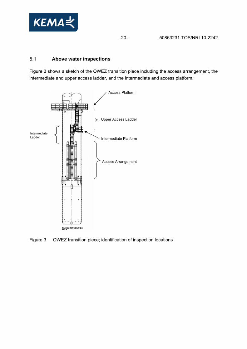
-20- 50863231-TOS/NRI 10-2242 5.1 Above water inspections Figure 3 shows a sketch of the OWEZ transition piece including the access arrangement, the intermediate and upper access ladder, and the intermediate and access platform.
Figure 3 OWEZ transition piece; identification of inspection locations
Upper Access Ladder
Intermediate Platform
Access Arrangement
Access Platform
Intermediate Ladder
-21- 50863231-TOS/NRI 10-2242 5.1.1 Inspection by boat In order to inspect the following items, the boat should sail around the transition piece. No Item Description
2.2.1 Access Arrangements − check general state of exterior including ladder, fender − check extent of marine growth
2.2.2 J-tubes − check general state of J-tubes as allowed to distance
5.1.2 Access arrangement No Item Description
2.3.1 Access Arrangements − see 2.2.1 − however, a closer inspection of the area behind
fender/ladder − check visually for coating damage and corrosion or
cracks − there are no bolted connections
5.1.3 Intermediate ladder No Item Description
2.4.1 Ladder − check general state of ladder − check doubler plates and welds to transition piece
for coating damage, corrosion and cracks − visual inspection only
2.4.2 Transition Piece − check for coating damage on transition piece − check visually for corrosion/pitting/cracks in the area
close to the intermediate platform
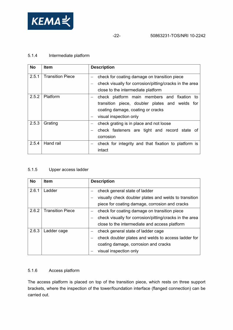
-22- 50863231-TOS/NRI 10-2242 5.1.4 Intermediate platform No Item Description
2.5.1 Transition Piece − check for coating damage on transition piece − check visually for corrosion/pitting/cracks in the area
close to the intermediate platform 2.5.2 Platform − check platform main members and fixation to
transition piece, doubler plates and welds for coating damage, coating or cracks
− visual inspection only 2.5.3 Grating − check grating is in place and not loose
− check fasteners are tight and record state of corrosion
2.5.4 Hand rail − check for integrity and that fixation to platform is intact
5.1.5 Upper access ladder No Item Description
2.6.1 Ladder − check general state of ladder − visually check doubler plates and welds to transition
piece for coating damage, corrosion and cracks 2.6.2 Transition Piece − check for coating damage on transition piece
− check visually for corrosion/pitting/cracks in the area close to the intermediate and access platform
2.6.3 Ladder cage − check general state of ladder cage − check doubler plates and welds to access ladder for
coating damage, corrosion and cracks − visual inspection only
5.1.6 Access platform The access platform is placed on top of the transition piece, which rests on three support brackets, where the inspection of the tower/foundation interface (flanged connection) can be carried out.
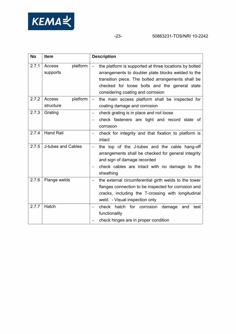
-23- 50863231-TOS/NRI 10-2242 No Item Description
2.7.1 Access platform supports
− the platform is supported at three locations by bolted arrangements to doubler plate blocks welded to the transition piece. The bolted arrangements shall be checked for loose bolts and the general state considering coating and corrosion
2.7.2 Access platform structure
− the main access platform shall be inspected for coating damage and corrosion
2.7.3 Grating − check grating is in place and not loose − check fasteners are tight and record state of
corrosion 2.7.4 Hand Rail − check for integrity and that fixation to platform is
intact 2.7.5 J-tubes and Cables − the top of the J-tubes and the cable hang-off
arrangements shall be checked for general integrity and sign of damage recorded
− check cables are intact with no damage to the sheathing
2.7.6 Flange welds − the external circumferential girth welds to the tower flanges connection to be inspected for corrosion and cracks, including the T-crossing with longitudinal weld. - Visual inspection only
2.7.7 Hatch − check hatch for corrosion damage and test functionality
− check hinges are in proper condition

-24- 50863231-TOS/NRI 10-2242 5.1.7 Interior, bulkhead deck No Item Description
2.8.1 Bulkhead − check around rim of bulkhead that fixation plate is intact
− inspect weld towards transition piece for corrosion or cracks
− visual inspection only 2.8.2 Flange welds − the internal circumferential girth welds to transition
piece flange connection to be inspected for corrosion and cracks.
− visual inspection only
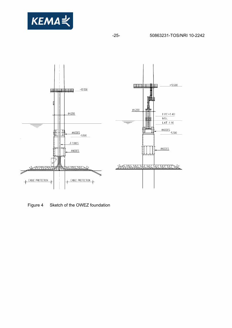
6 BELOW WATER INSPECTIONS The below water inspections of the foundations of the wind turbines will be carried out either by ROV or by divers (figure 4).
-25- 50863231-TOS/NRI 10-2242
Figure 4 Sketch of the OWEZ foundation
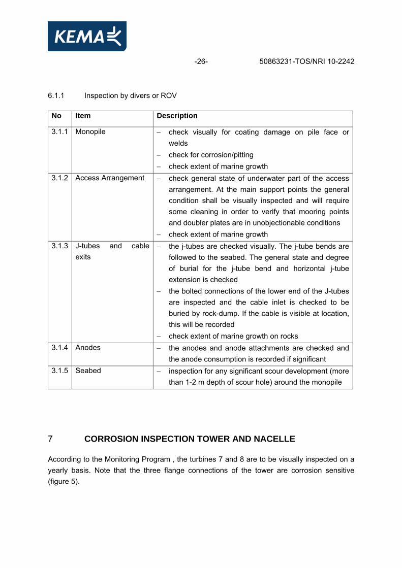
-26- 50863231-TOS/NRI 10-2242 6.1.1 Inspection by divers or ROV No Item Description
3.1.1 Monopile − check visually for coating damage on pile face or welds
− check for corrosion/pitting − check extent of marine growth
3.1.2 Access Arrangement − check general state of underwater part of the access arrangement. At the main support points the general condition shall be visually inspected and will require some cleaning in order to verify that mooring points and doubler plates are in unobjectionable conditions
− check extent of marine growth 3.1.3 J-tubes and cable
exits − the j-tubes are checked visually. The j-tube bends are
followed to the seabed. The general state and degree of burial for the j-tube bend and horizontal j-tube extension is checked
− the bolted connections of the lower end of the J-tubes are inspected and the cable inlet is checked to be buried by rock-dump. If the cable is visible at location, this will be recorded
− check extent of marine growth on rocks 3.1.4 Anodes − the anodes and anode attachments are checked and
the anode consumption is recorded if significant 3.1.5 Seabed − inspection for any significant scour development (more
than 1-2 m depth of scour hole) around the monopile
7 CORROSION INSPECTION TOWER AND NACELLE According to the Monitoring Program , the turbines 7 and 8 are to be visually inspected on a yearly basis. Note that the three flange connections of the tower are corrosion sensitive (figure 5).

-27- 50863231-TOS/NRI 10-2242 Figure 5 The OWEZ tower; identification of inspection locations of the three corrosion
sensitive flange connections
Top flange
Bottom flange
Middle flange
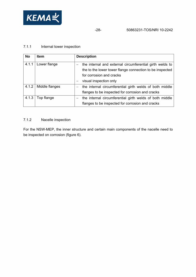
-28- 50863231-TOS/NRI 10-2242 7.1.1 Internal tower inspection No Item Description
4.1.1 Lower flange − the internal and external circumferential girth welds to the to the lower tower flange connection to be inspected for corrosion and cracks
− visual inspection only 4.1.2 Middle flanges − the internal circumferential girth welds of both middle
flanges to be inspected for corrosion and cracks 4.1.3 Top flange − the internal circumferential girth welds of both middle
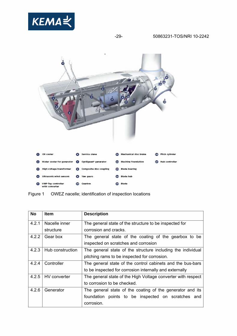
flanges to be inspected for corrosion and cracks 7.1.2 Nacelle inspection For the NSW-MEP, the inner structure and certain main components of the nacelle need to be inspected on corrosion (figure 6).
-29- 50863231-TOS/NRI 10-2242
Figure 1 OWEZ nacelle; identification of inspection locations No Item Description
4.2.1 Nacelle inner structure
The general state of the structure to be inspected for corrosion and cracks.
4.2.2 Gear box The general state of the coating of the gearbox to be inspected on scratches and corrosion
4.2.3 Hub construction The general state of the structure including the individual pitching rams to be inspected for corrosion.
4.2.4 Controller The general state of the control cabinets and the bus-bars to be inspected for corrosion internally and externally
4.2.5 HV converter The general state of the High Voltage converter with respect to corrosion to be checked.
4.2.6 Generator The general state of the coating of the generator and its foundation points to be inspected on scratches and corrosion.
-30- 50863231-TOS/NRI 10-2242 7.2 Periodic monitoring 7.2.1 General 1 The objective of Periodic Monitoring is the examination (inspection) of the machinery, the
safety devices and the structural integrity of the entire offshore wind turbine. 2 The body (called the operator in the following), who is responsible for the wind turbine,
shall arrange the Periodic Monitoring. The Inspection Report will be appended to the maintenance manual.
7.2.2 Scope of periodic monitoring 1 The turbine shall be checked by visual inspection, whereby each component shall be
examined reliably which includes cleaning and/or uncovering. 2 Structural integrity of the offshore wind turbine shall be checked including machinery, and
functioning of the safety and braking systems. 3 The scour protection, seabed level, underwater structure and splash zone shall be
checked by the review of the inspection reports of these components. 4 The structure within the splash zone shall be inspected visually with regard to corrosion,
marine growth and damage, e.g. from collision. If damages are found which indicate further problems, diver inspections will be requested. If there is an indication of excessive corrosion, plate thickness measurements will be required. This has to be reported in the inspection report.
5 The surfaces shall be inspected with the focus on cracks, abrasion, spalling and
corrosion of steel reinforcement and embedment. Particularly splash zone, ice conditions, and areas of previous repairs have to be checked. If it is necessary, the surface shall be cleaned. The result of the inspection has to be reported in the inspection report.
6 The type, location and extent of corrosion control, i.e. coatings, cathodic protection
system, as well as its effectiveness shall be reported in the inspection report. Additionally, repairs or replacements shall be reported as well.
The scope of additional inspections for Periodic Monitoring is listed in Table .

-31- 50863231-TOS/NRI 10-2242 Table 3 Scope of additional inspections for periodic monitoring
Assembly Inspection for / possible defects Rotor blade
− surface damage, cracks and structural discontinuities. (Inspection from a lifting or stepping device: visual and structural examination using suitable methods (e.g. tapping, ultrasonic testing)
− pretensioning of bolts − damage to the lightning protection system
Drive train
− leakages, unusual noises, condition of the corrosion protection, greasing, pretension of bolts
− condition of the gearing (oil sample, if relevant) − damage to the lightning protection system
Climate control, dehumidify and air filters − function, contamination, dirt Hydraulic system, pneumatic system − damage, leakages, corrosion, function Safety devices, outside lightings, sensors and braking systems
− functional checks, compliance with the limiting values, damage, wear
Control system and electrics including transformer station and switchgear, Condition Monitoring System
− terminals, fastenings, functional checks
Heli hoist, boat landing, fenders − fastenings, function Emergency shelter − description of all tasks shall be carried out at the outside
lighting and emergency shelter equipment as well as rescue at sea
− equipment and possible backup power supply (if applicable) Perusal of documentation
− completeness, observance of the conditions, construction according to certified documents, test documents, maintenance which is carried out at regular intervals
− if applicable: execution of modifications / repairs according to approval
8 INSPECTION RESULTS WIND FARM 8.1 The O&M inspections In 2007, 2008 and 2009, O&M inspections were carried according to the scheduled O&M inspections mentioned in chapter 4. The conditions and anomalies were reported for each of item number of systems and subsystems for the WTG foundations as describe in figure 2 (p. 13).

-32- 50863231-TOS/NRI 10-2242 The individual reports are listed in the reference list. An example of each report is listed in appendix II and III. 8.1.1 Inspections 2007 Coating inspections In March 2007, all wind turbines were inspected visually [5, 6, 7, 8]. The majority of the wind turbine population showed either no or only a limited amount of anomalies. Most of the anomalies were found at the transition piece platform, the secondary steel structure and the boat landing. Figure 7 shows a graphical overview of the distribution of the amount of anomalies reported per wind turbine.
75 ••
4 36• 12 6 29 • 35
• • • •11 21 28 34• • • •
10 20 27 33• • • •
9 19 26 32Coordination nr turbines • • • •
8 18 25Boundary nr location NSW • • •
7 17 31 1
* Meteo mast * • • • •6 24 30
1 reported anomaly • • •5 16 23
2 reported anomalies • • •4 15 22
3 or more reported anomalies • • •3 14• •
2 13• •
1•
• •3 2
Figure 7 Amount of reported anomalies of the coating inspections 2007
The reported anomalies comprise coating damages, incomplete coating layers and delaminating coating.
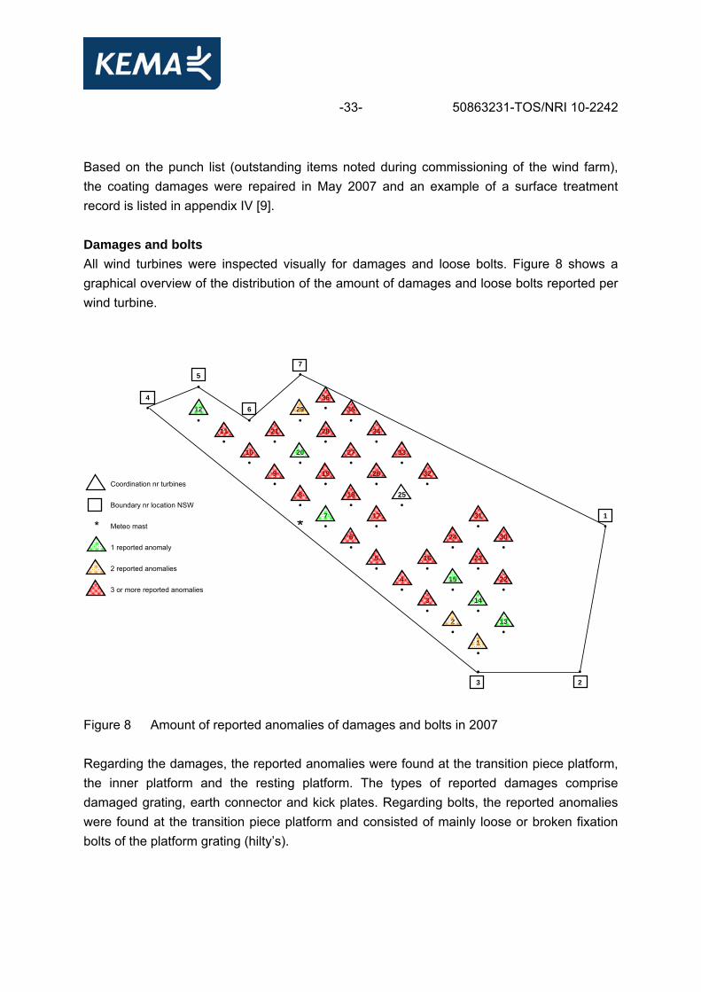
-33- 50863231-TOS/NRI 10-2242 Based on the punch list (outstanding items noted during commissioning of the wind farm), the coating damages were repaired in May 2007 and an example of a surface treatment record is listed in appendix IV [9]. Damages and bolts All wind turbines were inspected visually for damages and loose bolts. Figure 8 shows a graphical overview of the distribution of the amount of damages and loose bolts reported per wind turbine.
75 ••
4 36• 12 6 29 • 35
• • • •11 21 28 34• • • •
10 20 27 33• • • •
9 19 26 32Coordination nr turbines • • • •
8 18 25Boundary nr location NSW • • •
7 17 31 1
* Meteo mast * • • • •6 24 30
1 reported anomaly • • •5 16 23
2 reported anomalies • • •4 15 22
3 or more reported anomalies • • •3 14• •
2 13• •
1•
• •3 2
Figure 8 Amount of reported anomalies of damages and bolts in 2007 Regarding the damages, the reported anomalies were found at the transition piece platform, the inner platform and the resting platform. The types of reported damages comprise damaged grating, earth connector and kick plates. Regarding bolts, the reported anomalies were found at the transition piece platform and consisted of mainly loose or broken fixation bolts of the platform grating (hilty’s).

-34- 50863231-TOS/NRI 10-2242 Below water inspections The below water inspections were carried out by a ROV. The amount of the reported anomalies is shown in figure 9.
75 ••
4 36• 12 6 29 • 35
• • • •11 21 28 34• • • •
10 20 27 33• • • •
9 19 26 32Coordination nr turbines • • • •
8 18 25Boundary nr location NSW • • •
7 17 31 1
* Meteo mast * • • • •6 24 30
1 reported anomaly • • •5 16 23
2 reported anomalies • • •4 15 22• • •
3 14• •
2 13• •
1•
• •3 2
Figure 9 Amount of reported anomalies of the below water inspections in 2007
The amount of anomalies was limited and anomalies consisted mainly of not fully covered J-tubes in the amour layer, a missing anode or the continuity strip. The structure was not fully covered yet with marine growth (approximately 80%). However, the gradation of the marine growth until now is 30% of hard marine growth (1.4 g/cm²) and 70% of soft marine growth (1.2 g/cm²). More information can be found in the survey of marine fouling on turbine structures of the Offshore Windfarm Egmond aan Zee of 2008 and 2009 [14,15]. Cathodic protection In 2007, monitoring of the Cathodic Protect (CP) systems of all monopile foundations of the 36 wind turbines and the Metmast were executed by means of potential readings. The test results are described in report M760 M1 to 760M11 [20]. Overall results: − the level of protection of all steel monopiles is more than – 800mV, which is good − the effectiveness of the CP-system is according to the design.

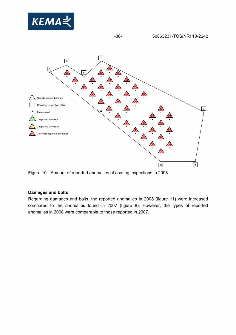
-35- 50863231-TOS/NRI 10-2242 8.1.2 Inspections 2008 Coating inspections In May 2008, all wind turbines were inspected visually [10, 11, 12]. Comparing the amount of reported anomalies of 2008 (figure 10) with those of 2007 (figure 7), it shows that the majority of the anomalies do not occur in a specific area of the wind farm. However, despite the coating repairs conducted in 2007, the amount of anomalies was increased. The reported and repeating anomalies comprises of: − corroded nuts under site resting platform due to contact erosion − several damages on the boat landing/steel surface − the removable hand railing (the hatch) and the platform border are damaged due to
hoisting activities − several damages on the hand railings near the round platform − connection tower and transition piece damaged − bad spots on the transition pile − bad spots on the J-tube − the outer coating layer of the transition pile, boat landing and j-tube damaged caused by
tie-up of the service ships − damaged spots near the hatch border. Some examples of the reported anomalies are depicted in appendix IV.
-36- 50863231-TOS/NRI 10-2242
75 ••
4 36• 12 6 29 • 35
• • • •11 21 28 34• • • •
10 20 27 33• • • •
9 19 26 32Coordination nr turbines • • • •
8 18 25Boundary nr location NSW • • •
7 17 31 1
* Meteo mast * • • • •6 24 30
1 reported anomaly • • •5 16 23
2 reported anomalies • • •4 15 22
3 or more reported anomalies • • •3 14• •
2 13• •
1•
• •3 2
Figure 10 Amount of reported anomalies of coating inspections in 2008 Damages and bolts Regarding damages and bolts, the reported anomalies in 2008 (figure 11) were increased compared to the anomalies found in 2007 (figure 8). However, the types of reported anomalies in 2008 were comparable to those reported in 2007.

-37- 50863231-TOS/NRI 10-2242
75 ••
4 36• 12 6 29 • 35
• • • •11 21 28 34• • • •
10 20 27 33• • • •
9 19 26 32Coordination nr turbines • • • •
8 18 25Boundary nr location NSW • • •
7 17 31 1
* Meteo mast * • • • •6 24 30
1 reported anomaly • • •5 16 23
2 reported anomalies • • •4 15 22
3 or more reported anomalies • • •3 14• •
2 13• •
1•
• •3 2
Figure 11 Amount of reported anomalies of damages and bolts in 2008
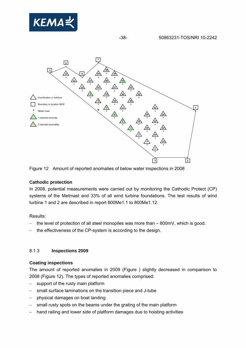
Below water inspections The amount of reported anomalies is shown in figure 12. The comparison of the amount of anomalies reported in 2007 and 2008 shows that the amount of anomalies decreased. All components were fully covered with hard marine growth, which made it more difficult to visually inspect the conditions of the foundation [14].
-38- 50863231-TOS/NRI 10-2242
75 ••
4 36• 12 6 29 • 35
• • • •11 21 28 34• • • •
10 20 27 33• • • •
9 19 26 32Coordination nr turbines • • • •
8 18 25Boundary nr location NSW • • •
7 17 31 1
* Meteo mast * • • • •6 24 30
1 reported anomaly • • •5 16 23
2 reported anomalies • • •4 15 22• • •
3 14• •
2 13• •
1•
• •3 2
Figure 12 Amount of reported anomalies of below water inspections in 2008 Cathodic protection In 2008, potential measurements were carried out by monitoring the Cathodic Protect (CP) systems of the Metmast and 33% of all wind turbine foundations. The test results of wind turbine 1 and 2 are described in report 800Me1.1 to 800Me1.12. Results: − the level of protection of all steel monopiles was more than – 800mV, which is good. − the effectiveness of the CP-system is according to the design. 8.1.3 Inspections 2009 Coating inspections The amount of reported anomalies in 2009 (Figure ) slightly decreased in comparison to 2008 (Figure 12). The types of reported anomalies comprised: − support of the rusty main platform − small surface laminations on the transition piece and J-tube − physical damages on boat landing − small rusty spots on the beams under the grating of the main platform − hand railing and lower side of platform damages due to hoisting activities
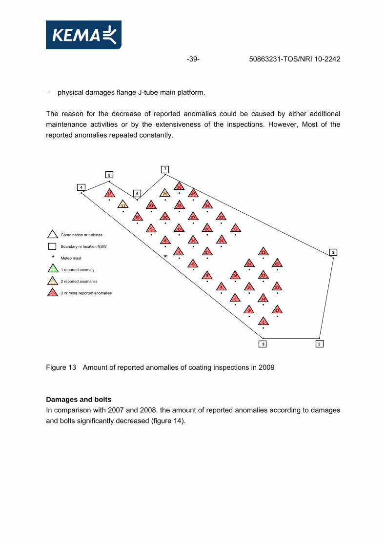
-39- 50863231-TOS/NRI 10-2242 − physical damages flange J-tube main platform. The reason for the decrease of reported anomalies could be caused by either additional maintenance activities or by the extensiveness of the inspections. However, Most of the reported anomalies repeated constantly.
75 ••
4 36• 12 6 29 • 35
• • • •11 21 28 34• • • •
10 20 27 33• • • •
9 19 26 32Coordination nr turbines • • • •
8 18 25Boundary nr location NSW • • •
7 17 31 1
* Meteo mast * • • • •6 24 30
1 reported anomaly • • •5 16 23
2 reported anomalies • • •4 15 22
3 or more reported anomalies • • •3 14• •
2 13• •
1•
• •3 2
Figure 13 Amount of reported anomalies of coating inspections in 2009 Damages and bolts In comparison with 2007 and 2008, the amount of reported anomalies according to damages and bolts significantly decreased (figure 14).

-40- 50863231-TOS/NRI 10-2242
75 ••
4 36• 12 6 29 • 35
• • • •11 21 28 34• • • •
10 20 27 33• • • •
9 19 26 32Coordination nr turbines • • • •
8 18 25Boundary nr location NSW • • •
7 17 31 1
* Meteo mast * • • • •6 24 30
1 reported anomaly • • •5 16 23
2 reported anomalies • • •4 15 22
3 or more reported anomalies • • •3 14• •
2 13• •
1•
• •3 2
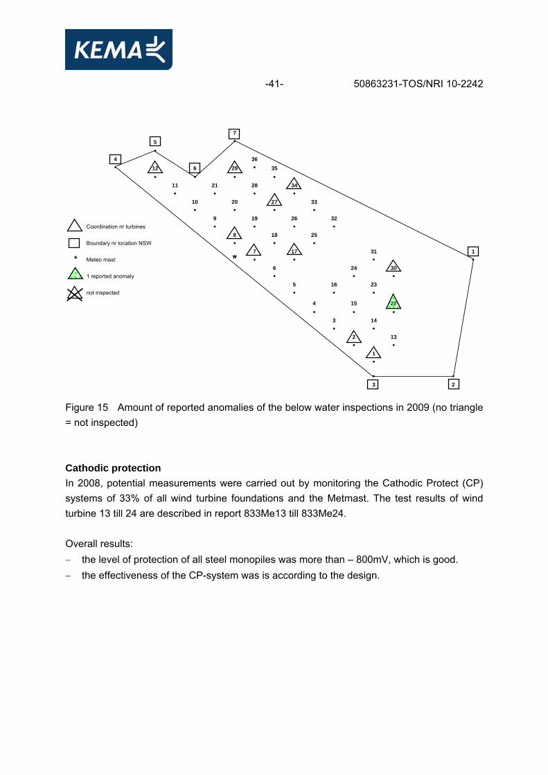
Figure 14 Amount of reported anomalies of damages and bolts in 2009 Below water inspections In 2009, the ROV inspections covered 33% of the total amount of wind turbines. Due to the intended changes in the inspected wind turbine population (refer to chapter 4.2.3), it is difficult to detect a trend (if any) with respect to the amount of reported anomalies. There were no particular anomalies reported in 2009 (figure 15).
-41- 50863231-TOS/NRI 10-2242
75 ••
4 36• 12 6 29 • 35
• • • •11 21 28 34• • • •
10 20 27 33• • • •
9 19 26 32Coordination nr turbines • • • •
8 18 25Boundary nr location NSW • • •
7 17 31 1
* Meteo mast * • • • •6 24 30
1 reported anomaly • • •5 16 23
not inspected • • •4 15 22
• • •3 14• •
2 13• •
1•
• •3 2
Figure 15 Amount of reported anomalies of the below water inspections in 2009 (no triangle = not inspected) Cathodic protection In 2008, potential measurements were carried out by monitoring the Cathodic Protect (CP) systems of 33% of all wind turbine foundations and the Metmast. The test results of wind turbine 13 till 24 are described in report 833Me13 till 833Me24. Overall results: − the level of protection of all steel monopiles was more than – 800mV, which is good. − the effectiveness of the CP-system was is according to the design.
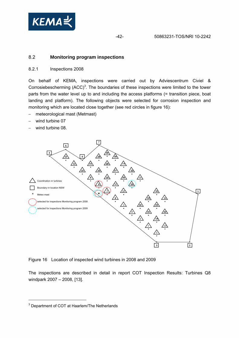
-42- 50863231-TOS/NRI 10-2242 8.2 Monitoring program inspections 8.2.1 Inspections 2008 On behalf of KEMA, inspections were carried out by Adviescentrum Civiel & Corrosiebescherming (ACC)3. The boundaries of these inspections were limited to the tower parts from the water level up to and including the access platforms (= transition piece, boat landing and platform). The following objects were selected for corrosion inspection and monitoring which are located close together (see red circles in figure 16): − meteorological mast (Metmast) − wind turbine 07 − wind turbine 08.
75 ••
4 36• 12 6 29 • 35
• • • •11 21 28 34• • • •
10 20 27 33• • • •
9 19 26 32Coordination nr turbines • • • •
8 18 25Boundary nr location NSW • • •
7 17 31 1
* Meteo mast * • • • •6 24 30
selected for inspections Monitoring program 2008 • • •5 16 23
selected for inspections Monitoring program 2009 • • •4 15 22• • •
3 14• •
2 13• •
1•
• •3 2
Figure 16 Location of inspected wind turbines in 2008 and 2009 The inspections are described in detail in report COT Inspection Results: Turbines Q8 windpark 2007 – 2008, [13].
3 Department of COT at Haarlem/The Netherlands
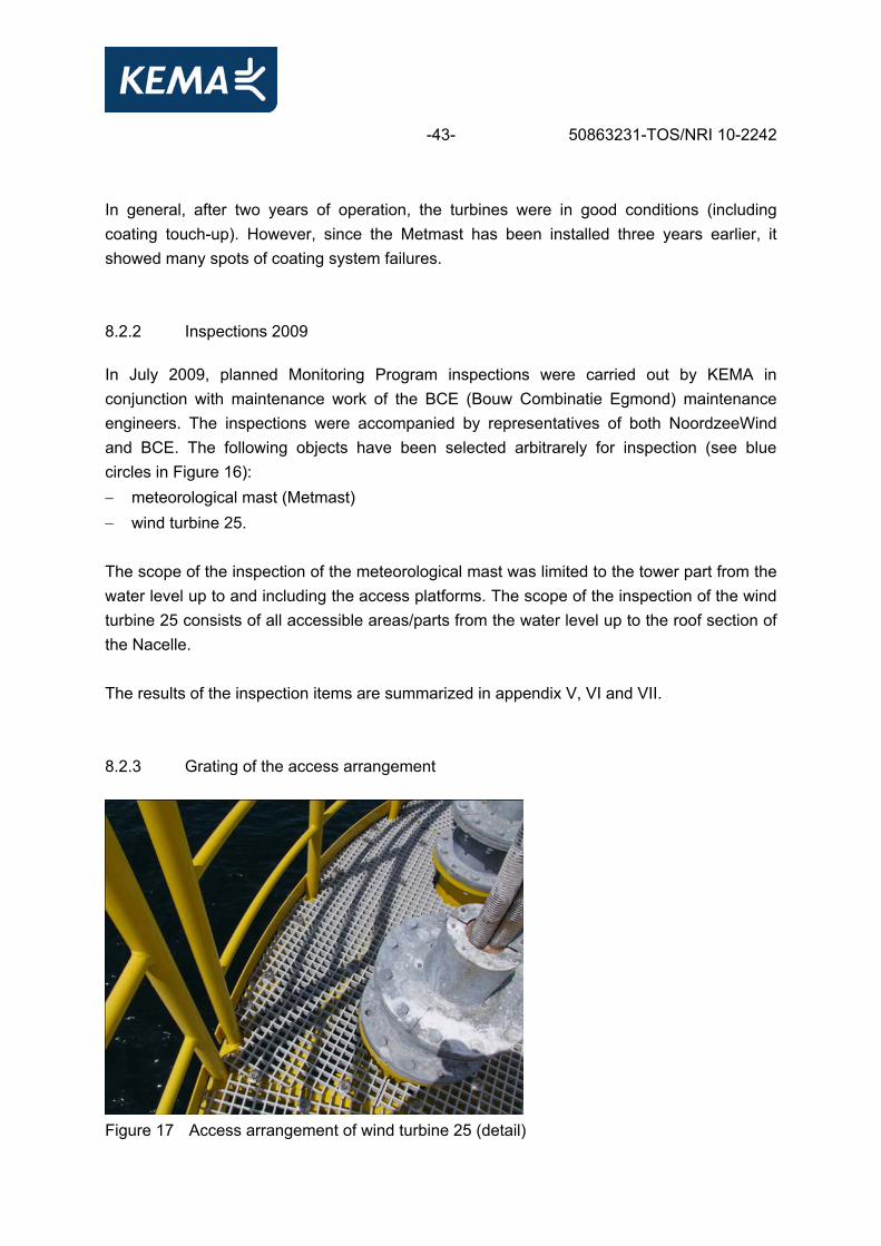
-43- 50863231-TOS/NRI 10-2242 In general, after two years of operation, the turbines were in good conditions (including coating touch-up). However, since the Metmast has been installed three years earlier, it showed many spots of coating system failures. 8.2.2 Inspections 2009 In July 2009, planned Monitoring Program inspections were carried out by KEMA in conjunction with maintenance work of the BCE (Bouw Combinatie Egmond) maintenance engineers. The inspections were accompanied by representatives of both NoordzeeWind and BCE. The following objects have been selected arbitrarely for inspection (see blue circles in Figure 16): − meteorological mast (Metmast) − wind turbine 25. The scope of the inspection of the meteorological mast was limited to the tower part from the water level up to and including the access platforms. The scope of the inspection of the wind turbine 25 consists of all accessible areas/parts from the water level up to the roof section of the Nacelle. The results of the inspection items are summarized in appendix V, VI and VII. 8.2.3 Grating of the access arrangement
Figure 17 Access arrangement of wind turbine 25 (detail)
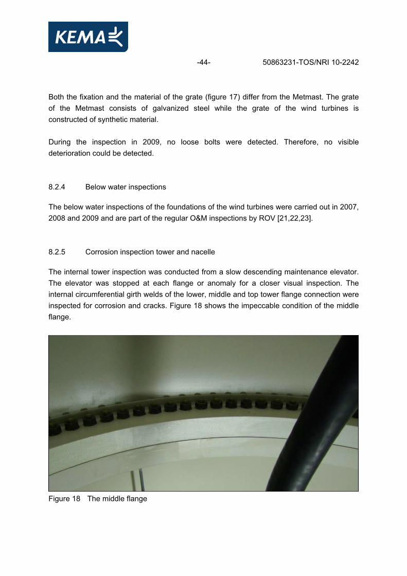
-44- 50863231-TOS/NRI 10-2242 Both the fixation and the material of the grate (figure 17) differ from the Metmast. The grate of the Metmast consists of galvanized steel while the grate of the wind turbines is constructed of synthetic material. During the inspection in 2009, no loose bolts were detected. Therefore, no visible deterioration could be detected. 8.2.4 Below water inspections The below water inspections of the foundations of the wind turbines were carried out in 2007, 2008 and 2009 and are part of the regular O&M inspections by ROV [21,22,23]. 8.2.5 Corrosion inspection tower and nacelle The internal tower inspection was conducted from a slow descending maintenance elevator. The elevator was stopped at each flange or anomaly for a closer visual inspection. The internal circumferential girth welds of the lower, middle and top tower flange connection were inspected for corrosion and cracks. Figure 18 shows the impeccable condition of the middle flange.
Figure 18 The middle flange
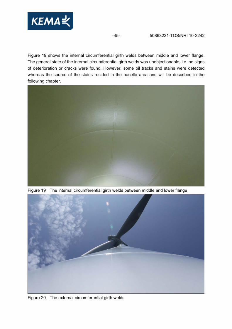
-45- 50863231-TOS/NRI 10-2242 Figure 19 shows the internal circumferential girth welds between middle and lower flange. The general state of the internal circumferential girth welds was unobjectionable, i.e. no signs of deterioration or cracks were found. However, some oil tracks and stains were detected whereas the source of the stains resided in the nacelle area and will be described in the following chapter.
Figure 19 The internal circumferential girth welds between middle and lower flange
Figure 20 The external circumferential girth welds
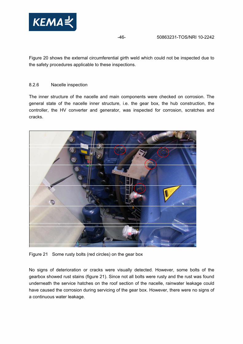
-46- 50863231-TOS/NRI 10-2242 Figure 20 shows the external circumferential girth weld which could not be inspected due to the safety procedures applicable to these inspections. 8.2.6 Nacelle inspection The inner structure of the nacelle and main components were checked on corrosion. The general state of the nacelle inner structure, i.e. the gear box, the hub construction, the controller, the HV converter and generator, was inspected for corrosion, scratches and cracks.
Figure 21 Some rusty bolts (red circles) on the gear box
No signs of deterioration or cracks were visually detected. However, some bolts of the gearbox showed rust stains (figure 21). Since not all bolts were rusty and the rust was found underneath the service hatches on the roof section of the nacelle, rainwater leakage could have caused the corrosion during servicing of the gear box. However, there were no signs of a continuous water leakage.
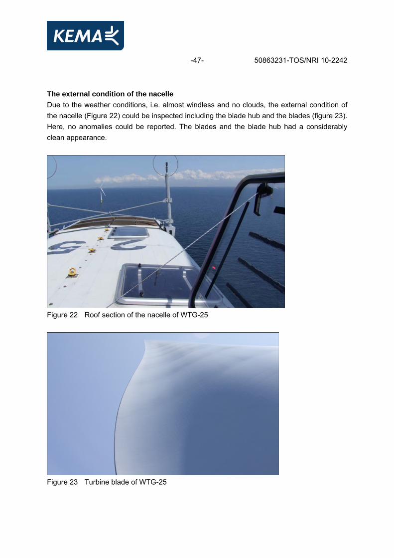
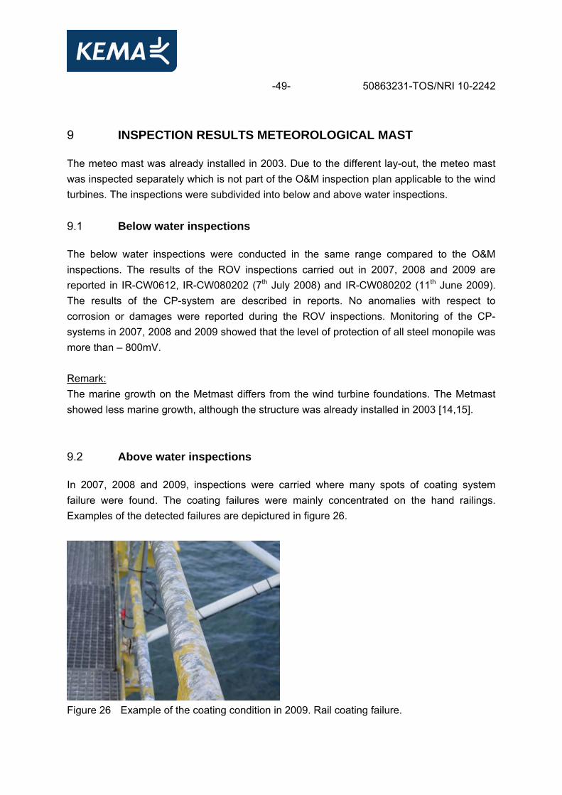
-47- 50863231-TOS/NRI 10-2242 The external condition of the nacelle Due to the weather conditions, i.e. almost windless and no clouds, the external condition of the nacelle (Figure 22) could be inspected including the blade hub and the blades (figure 23). Here, no anomalies could be reported. The blades and the blade hub had a considerably clean appearance.
Figure 22 Roof section of the nacelle of WTG-25
Figure 23 Turbine blade of WTG-25

-48- 50863231-TOS/NRI 10-2242
Figure 24 Grating underneath the high voltage transformer
Underneath the high voltage transformer, the bolts near the grating showed either grease stains or corrosion (figure 24). The smeared stripes on the right side of the grate (figure 24, red arrow) were caused by corrosion product originated from the bolts.
Figure 25 The connection of the turbine blade to the blade hub (R) and top view of the
blade hub (L)
Aside from some mechanical damages, the general condition of the coating showed no anomalies (figure 25). No staining or coating damages were visually detected.
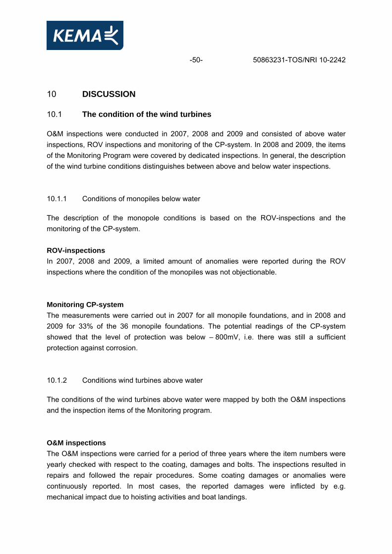
-49- 50863231-TOS/NRI 10-2242 9 INSPECTION RESULTS METEOROLOGICAL MAST The meteo mast was already installed in 2003. Due to the different lay-out, the meteo mast was inspected separately which is not part of the O&M inspection plan applicable to the wind turbines. The inspections were subdivided into below and above water inspections. 9.1 Below water inspections The below water inspections were conducted in the same range compared to the O&M inspections. The results of the ROV inspections carried out in 2007, 2008 and 2009 are reported in IR-CW0612, IR-CW080202 (7th July 2008) and IR-CW080202 (11th June 2009). The results of the CP-system are described in reports. No anomalies with respect to corrosion or damages were reported during the ROV inspections. Monitoring of the CP-systems in 2007, 2008 and 2009 showed that the level of protection of all steel monopile was more than – 800mV. Remark: The marine growth on the Metmast differs from the wind turbine foundations. The Metmast showed less marine growth, although the structure was already installed in 2003 [14,15]. 9.2 Above water inspections In 2007, 2008 and 2009, inspections were carried where many spots of coating system failure were found. The coating failures were mainly concentrated on the hand railings. Examples of the detected failures are depictured in figure 26.
Figure 26 Example of the coating condition in 2009. Rail coating failure.
-50- 50863231-TOS/NRI 10-2242 10 DISCUSSION 10.1 The condition of the wind turbines O&M inspections were conducted in 2007, 2008 and 2009 and consisted of above water inspections, ROV inspections and monitoring of the CP-system. In 2008 and 2009, the items of the Monitoring Program were covered by dedicated inspections. In general, the description of the wind turbine conditions distinguishes between above and below water inspections. 10.1.1 Conditions of monopiles below water The description of the monopole conditions is based on the ROV-inspections and the monitoring of the CP-system. ROV-inspections In 2007, 2008 and 2009, a limited amount of anomalies were reported during the ROV inspections where the condition of the monopiles was not objectionable. Monitoring CP-system The measurements were carried out in 2007 for all monopile foundations, and in 2008 and 2009 for 33% of the 36 monopile foundations. The potential readings of the CP-system showed that the level of protection was below – 800mV, i.e. there was still a sufficient protection against corrosion. 10.1.2 Conditions wind turbines above water The conditions of the wind turbines above water were mapped by both the O&M inspections and the inspection items of the Monitoring program. O&M inspections The O&M inspections were carried for a period of three years where the item numbers were yearly checked with respect to the coating, damages and bolts. The inspections resulted in repairs and followed the repair procedures. Some coating damages or anomalies were continuously reported. In most cases, the reported damages were inflicted by e.g. mechanical impact due to hoisting activities and boat landings.
-51- 50863231-TOS/NRI 10-2242 In the case of recurring damages, these parts should be repaired and protected for future mechanical impacts. Based on the results, it can be concluded that the corrosion protection of the wind turbines is effective. Monitoring program The scope of the monitoring program inspection covered the complete wind turbine structure. According to the results of 2009, the inspections showed only minor irregularities like oil leakage, or some rusty nuts or bolts. It should be worthwhile to combine the checklist of the monitoring program with other service activities. When work is planned in the nacelle, the service engineers can fill out a checklist with accompanying pictures. This can provide valuable additional information. The reported anomalies like staining or leakages will trigger the service engineer to plan/take the proper actions. 10.2 The condition of the meteo mast The coating system is flaking off the construction. However, the corrosion has been prevented due to the metalized steel underneath the coating system. The J-tubes are showing several mechanical damages caused by boat hulls which could initiate marine degradation problems, i.e. chlorine-induced corrosion. According to this, some corrosion spots have been detected at the transition piece possibly caused by mechanical damages (examples of reported mechanical damages are depicted in appendix V) . A lot of delamination is present between the first (galvanised) layer and the painting system. There are major damages in the paint layers near important joints of the steel construction. A lot of these damages were caused by surface defects such as surface laminations, welding pin holes, sharp edges, etc. After the paint application, delamination can be caused by wrong application or preparation as well as environmental influences, i.e. humidity and temperature. [18]. The extent, type and amount of reported coating damage of the Metmast are increased in comparison with the wind turbines. The following factors may have contributed to the present condition of the Metmast: − the Metmast was erected several years earlier than the wind turbines − the coating system applied at the Metmast differs from the wind turbines. Additionally, the Metmast is frequently visited by birds, which is identified by the presence of bird droppings & litter and even dried fish (figure 27).

-52- 50863231-TOS/NRI 10-2242
Figure 27 Dried fish and bird litter on the grate of the Metmast
10.2.1 The influence of bird droppings and digestive pancreatic enzymes on coating
degradation Bird excrement contains fungi and bacteria which are known to cause pneumonia as well as systemic infections. Additionally, the excrements contain highly acidic concentrates such as uric acid (pH 3.0 - 4.5) which can cause corrosion. Several studies were conducted to investigate the effect of biological materials like natural bird excrements and digestive pancreatic enzymes on (automotive) coatings, e.g. Ramezanzadeh et al. [24]. The results showed that the biological materials have an extremely strong effect on the appearance of the coatings and are responsible for the catalyzing of the hydrolytic degradation. Therefore, it can be concluded that a biological degradation mechanism has an additional influence on the degradation of metallic materials.
-53- 50863231-TOS/NRI 10-2242 10.2.2 Coating system of the meteo mast and wind turbine Different kinds of applied coating systems are used for the met mast and the wind turbine. Therefore, it is difficult to draw conclusions on the performance of the different coating systems. Moreover, both coating systems were checked by visual inspections and carried out by different corrosion engineers. Additionally, the Metmast is approximately 3 years older than the wind turbines. However, the results of the wind turbine inspections tends to be better than the results of the Metmast inspections. Future inspections of the coating performance between the meteo mast and the wind turbines will reveal whether the off-set either decreases or increases. If the off-set decrease, it will tend towards the impact of ageing on the coating performance of the wind turbine coating system. If the off-set increases, it will cause a poorer coating performance of the meteo mast compared to the coating system applied on the wind turbines. 10.3 Bio fouling versus corrosion The report "Survey of marine fouling on turbine support structures of the Offshore Wind farm Egmond aan Zee, June 2009" [15] describes the results of the ROV inspections. Fouling starts with the development of a biofilm. After the biofilm has set, it becomes possible for macrofouling species to settle. This macrofouling forms a thick layer, depending on the species size and characteristics of growth and attachment. In general, at the surface side of a fouling layer, underneath the biofilm, an anaerobic environment develops because of the absence of oxygen. The oxygen is used up by the organisms on the upper side of the biofilm. Within the anaerobic environment, organisms like sulphate reducing bacteria (SRB’s) may enhance the development of MIC (Microbial Influenced Corrosion). In order to protect the transition piece, the surface is coated. The main macrofouling (hard fouling) community observed are mussels. With respect to the structural integrity of the transition piece and the monopile, it can be noted that there is a strong indication that the marine growth regulates itself. Within the mussel community, the mussels at the lower side, i.e. the specimens that attach to the surface, will have less fresh water to filter for oxygen and nutrients that the mussels on the outer side of the layer which are exposed to the aquatic environment. The mussels that provide the attachment of the layer to the coated surface are thereby expected to have a higher mortality rate. As soon as mussels die, the shells open and the inner body tissue goes out of the shells quickly. The byssus threads by which they attach are lost as well, leaving no connection. Therefore, when the mussels die the connection to the surface is lost and hence it becomes easier to remove
-54- 50863231-TOS/NRI 10-2242 this layer by means of the water velocity. Foremost the mussels are able to form thick layers of fouling, at this moment, as assessed from the video images, up to 30 cm in thickness. The other, soft fouling species do not form thick layers as these do not cluster. When the clusters of mussels are > 15 cm thick, due to currents during the tides (up to 3 m/s) and mortality of the specimens attached to the surface (underneath), patches and clusters of mussels could come loose from the surface, leaving open spaces where new marine growth can develop. It was indeed observed that patches of mussel fouling fell off the surface, whereby no indication of coating damage has been observed. It was also observed that small, young mussels have settled in these 'empty' areas. Based on the observed surfaces, no signs of material degradation of the transition pieces due to fouling have been observed during this monitoring session. Several species like the Japanese oyster and barnacles cement themselves to a surface. These species are difficult to remove due to a very tight adhesion. When being removed (only manually), the chance exists that the coating becomes damaged. However, only a limited number of these species have been observed so far and only at the MetMast manual cleaning has been performed. 10.4 Codes and standards The results of the Monitoring Program are not giving reason for changes with respect to the codes and standards applicable to the NSW wind farm.
11 CONCLUSIONS The materials specifications, the quality control, the coating procedures as well as the CP-system of the wind turbines showed that they are effective for the offshore environment off the coast of Egmond aan zee. Most of the reported damages and anomalies are related to mechanical impact, while none of the reported anomalies could be linked to the occurrence of any disruptions causing unplanned downtime. The Metmast suffers from some coating system problems which require repair and yearly monitoring in conjunction with annual O&M inspections of the wind turbines in order to investigate the ageing effects.
-55- 50863231-TOS/NRI 10-2242 12 RECOMMENDATIONS The monitoring of the condition of the wind farm will continue by conducting annual O&M inspections. It may be worthwhile to map the type and amount of reported anomalies. If the mechanical damages keep repeating, extra care should be taken during maintenance activities. Additional shields or covers at most vulnerable places and/or wooden fenders at boat landings may be applied to reduce the damages of mechanical impact. In some cases, the reported damage is not only caused by mechanical impact, but could also be related to a less effective coating repair. In these cases, extra attention is required for the coating procedure and the coating application.
-56- 50863231-TOS/NRI 10-2242 REFERENCES 1 Vestas, 2005. Quality Specification. Surface Treatment of tower and foundation sections
for Vestas wind turbines, item-no 990509.R1 26 april 2005 2 Infra, 2006. Material Specification Coating, 10020244-31-60-GA-0630-2 3 KEMA, 2006. Adaptations to a marine climate, salt and water, The Inspection &
Maintenance plan, OWEZ_R_111_110606. 5069999-TOS/LEN 06-4677 4 KEMA, 2006. Biological Fouling. Pre-survey of marine fouling on turbine support
structures of the Offshore Windfarm Egmond aan Zee. OWEZ_R_112_July 19 2006. 50562062-TOS/MEC 06-9409
5 Ballast Nedam, 2007. Civil Above water inspections 2007, IR260307 TP 01 – TP 36 Ballast or Bladt
6 Ballast Nedam, 2007. Civil Above water inspections 2007, IR260307 TP 01 – TP 36 Boat Landing
7 Ballast Nedam, 2007. Civil Above water inspections 2007, 20070911 – IR AboveWaterCoating WTG 01 – WTG 36
8 Ballast Nedam, 2007. Civil Above water inspections 2007, 20070911 – IR AboveDamages&Bolts WTG 01 – WTG 36
9 Gardit A/S, 2007. Surface treatment record Q8 Holland – Rep, Tower 1 – 36 10 Ballast Nedam, 2008. Civil Above water inspections 2008, Inspection TP01-TP36 080525 11 Ballast Nedam, 2008. Civil Above water inspections 2008, Inspection Sheet WTG01-
WTG36 Coatings 12 Ballast Nedam, 2008. Civil Above water inspections 2008, Inspection Sheet WTG01-
WTG36 Damages & Bolts 13 COT, 2008. COT Inspection Results: Turbines Q8 windpark 2007 – 2008, ACC08-1076-
REP 14 KEMA, 2008. Biological Fouling. Survey of marine fouling on turbine support structures of
the Offshore Windfarm Egmond aan Zee, July 2008. OWEZ_R_112_T1_2010211_biofouling_2008.
15 KEMA, 2009. Biological Fouling. Survey of marine fouling on turbine support structures of the Offshore Windfarm Egmond aan Zee, June 2009. OWEZ_R_112_T1_2010226_biofouling_2009.
16 Bladt, 2005. Bladt Coating manual. 380993/330730. 17 EPC and Operations and Maintenance, Schedule 4.2; Policies, standards and codes,
Rev H, 07-03-2005 18 Ballast Nedam, 2008. Inspection of the Meteomast. BNEOE-CS-SF-417 19 Vesta, 2007. Operation & Maintenance Manual Civil, BNEOE-WP-MD-309 170407 rev.4
-57- 50863231-TOS/NRI 10-2242 20 Corrosie Consultancy van de Meer, 2007. Monitoring Report Cathodic Protection System
36 Monopile foundations wind turbines 1 monopile foundation meteomast. 492650 IP-2007-0056-00.0 760.
21 Wals diving & marine, 2007. Inspection Sheet WTG 01- WTG 36. 20070521 22 Wals diving & marine, 2008. INSPECTION REPORT O&M 2008 Underwater survey. IR-
CW080202 Rev 0 23 Wals diving & marine, 2009. Inspection sheets of MM, WTG1, WTG2, WTG7, WTG8,
WTG17, WTG22, WTG27, WTG 29, WTG30, WTG32. 24 Ramezanzadeh, B et al, 2009. An evaluation of an automotive clear coat performance
exposed to bird droppings under different testing approaches. Progress in Organic Coatings, Volume 66, Issue 2, October 2009, Pages 149-160.

-58- 50863231-TOS/NRI 10-2242 APPENDIX I REFERENCE LIST CORROSION PROTECTION,
COATINGS & PAINTINGS Specification materials, corrosion protection, coatings and paintings - Document 10020244-31-00-GA-0010, Design criteria Wind Turbine and Foundation,. - Document 10020244-31-60-GA-0610, Material Specification secondary Steel - Document 10020244-31-60-GA-0660, Material Specification secondary Steel - Document 10020244-31-60-GA-0630-2, Material Specification Coating. - Document NSW-70.04-10, Cathodic Protection detailed design. - Document 380993/330730. Bladt Coating manual. - Document 990509.R1, Quality Specification. Surface Treatment of towers and foundation
sections for Vestas turbines - Document 990968.R0, Technical Surface Specification. Offshore surface treatment of
towers - Document Shell Expro ES/115, Corrosion Protection of Fixed Steel Structures: Offshore
Installations - Document Shell Expro ES/011, Painting and Coating System Vol 1, 2 & 3 Codes and Standards - NACE RP 0176-94. Recommended Practices Cathodic Design. - DNV RP-B401. Cathodic Protection Design. - NEN-EN 12495 CP for fixed steel offschore structures. - Shell Expro ES/115, Corrosion Protection of Fixed Steel Structures: Offshore
Installations. - DNV-OS-C40,1 Fabrication and testing of of-shore structures. - ISO 8501-1. Prepation of steel substrates before application of paint and related
products, visual assessment of surface cleanliness. - ISO 8502-6. Preparation of steel substrates before application of paints and related
products -- Tests for the assessment of surface cleanliness -- Part 6: Extraction of soluble contaminants for analysis -- The Bresle method.
- ISO-8502-9. Preparation of steel substrates before application of paints and related products -- Tests for the assessment of surface cleanliness -- Part 9: Field method for the conductometric determination of water-soluble salts.
-59- 50863231-TOS/NRI 10-2242 - ISO 11127-6 Preparation of steel substrates before application of paints and related
products -- Test methods for non-metallic blast-cleaning abrasives -- Part 6: Determination of water-soluble contaminants by conductivity measurement.
- SSPC-SP10. Near-White Blast Cleaning -- Surface Preparation Standards of Steel Structures Paining Counsel – complies with NACE No. 2.
- ISO 8503-1. Prepation of steel substrates before application of paint and related products, surface roughness characteristics of blast cleaned steel substrates.
- BN 11b Rugotest No. 3. Comparison standard for blasted surfaces. The method complies with ASTM D 4417/A.
- ISO 2813. Paints and varnishes -- Determination of specular gloss of non-metallic paint films at 20 degrees, 60 degrees and 85 degrees.
- ASTDM D523. Standard Test Method for Specular Gloss. - ISO 4624. Paints and varnishes -- Pull-off test for adhesion. - ISO 12944, Corrosion protection of steel structures by protective paint. - ISO 2063, Thermal spraying –Metallic and other inorganic coatings – Zinc, aluminium
and their alloys. - ISO 4828, Paint and varnishes – Evaluation of degradation of coatings – Design quantity
and size of defects and of intensity of uniform changes in appearance.

-60- 50863231-TOS/NRI 10-2242 APPENDIX II O&M COATING INSPECTION
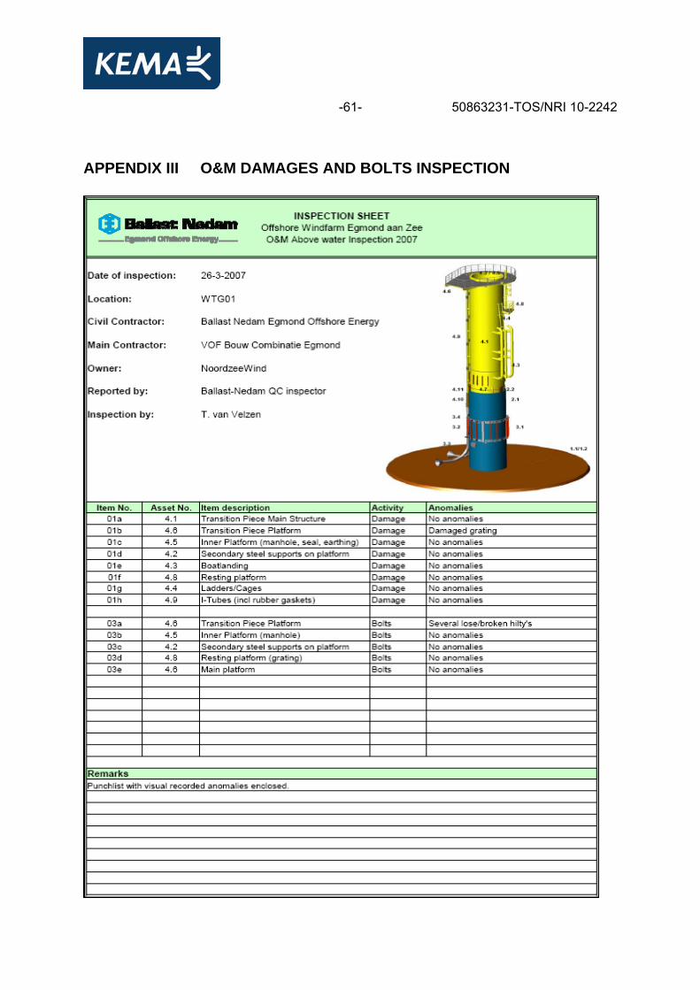
-61- 50863231-TOS/NRI 10-2242 APPENDIX III O&M DAMAGES AND BOLTS INSPECTION
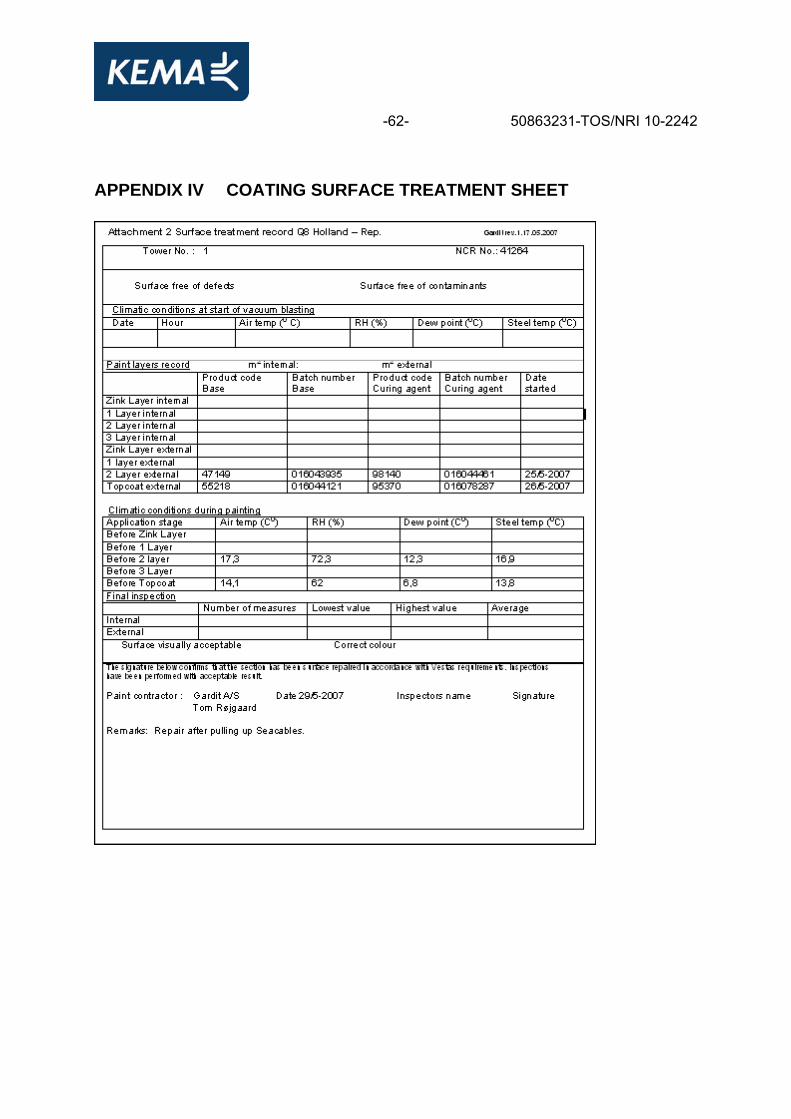
-62- 50863231-TOS/NRI 10-2242 APPENDIX IV COATING SURFACE TREATMENT SHEET

-63- 50863231-TOS/NRI 10-2242 APPENDIX V EXAMPLES OF REPORTED ANOMALIES
Figure V.1 Corroded nuts under site resting platform due to contact erosion (WTG-04)
Figure V.2 Several damages on the boat landing/steel surface (WTG-02)
Figure V.3 Several damages on the hand railings near the round platform (WTG-01)
-64- 50863231-TOS/NRI 10-2242
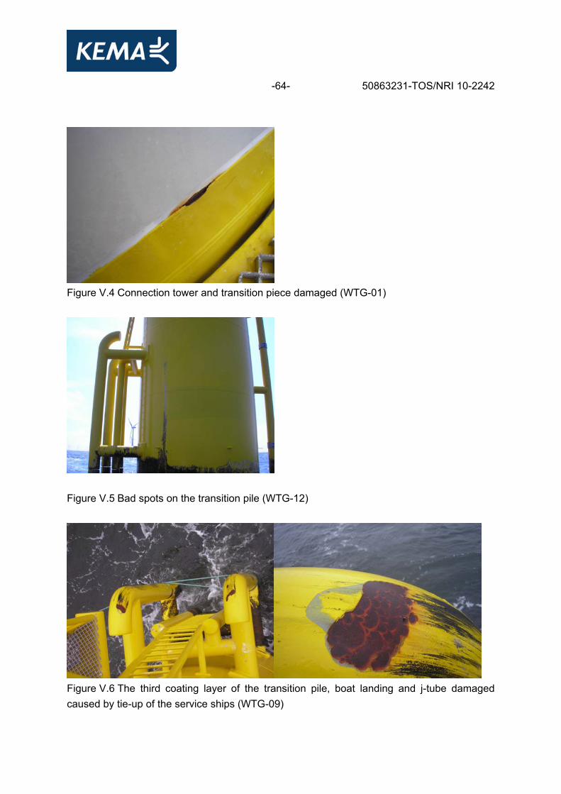
Figure V.4 Connection tower and transition piece damaged (WTG-01)
Figure V.5 Bad spots on the transition pile (WTG-12)
Figure V.6 The third coating layer of the transition pile, boat landing and j-tube damaged caused by tie-up of the service ships (WTG-09)
-65- 50863231-TOS/NRI 10-2242
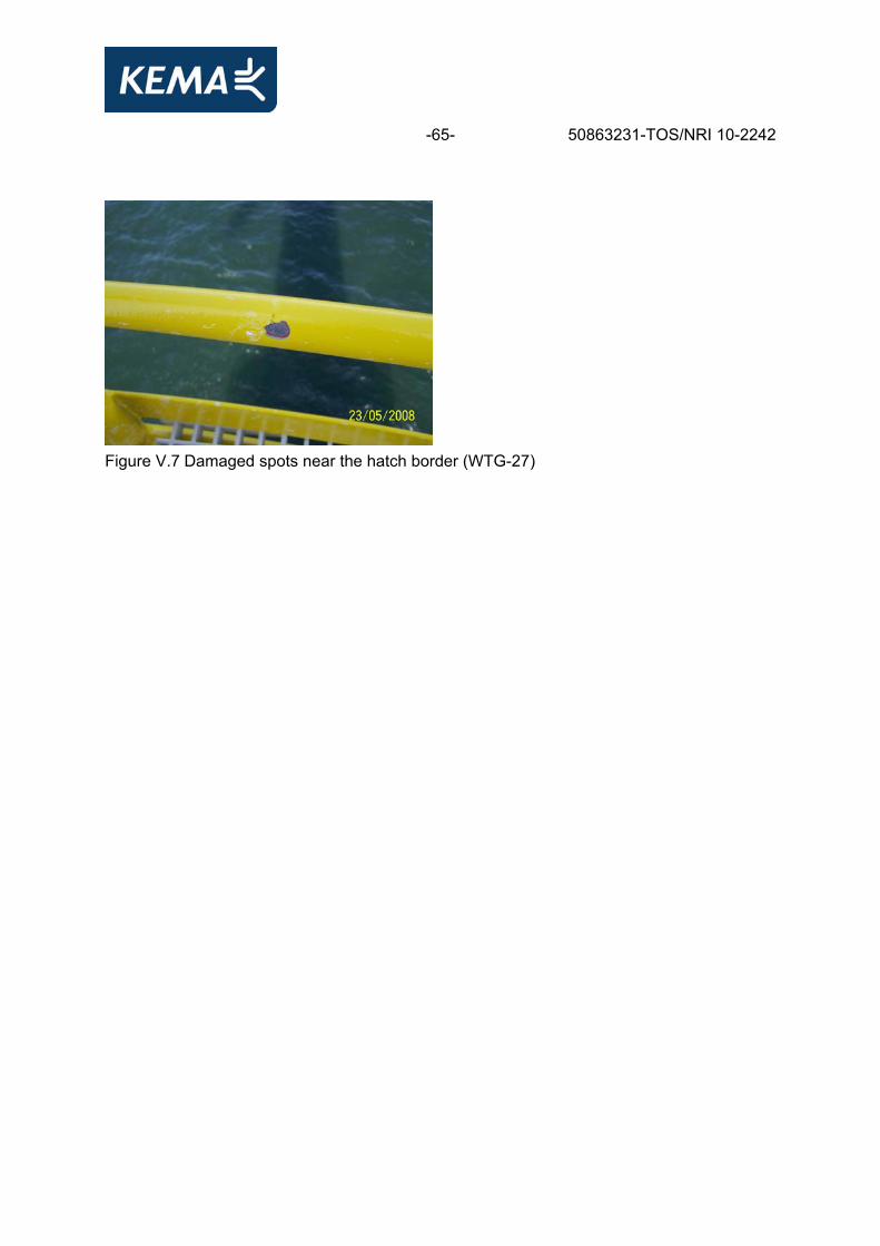
Figure V.7 Damaged spots near the hatch border (WTG-27)
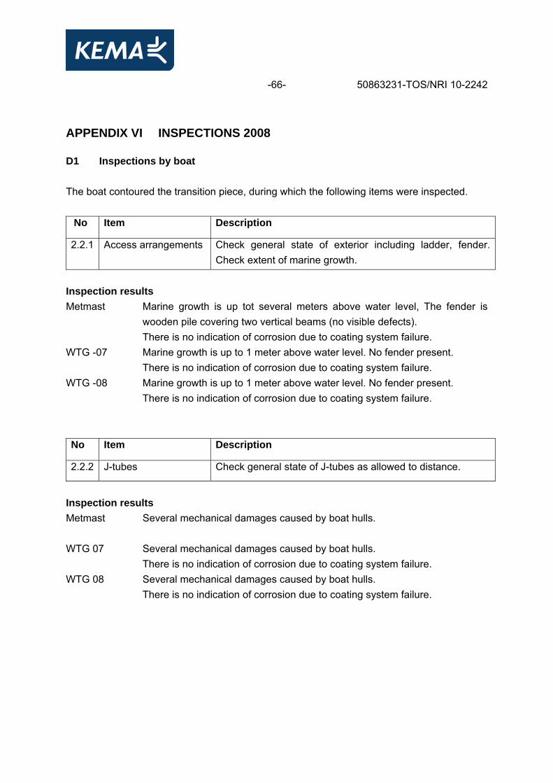
-66- 50863231-TOS/NRI 10-2242 APPENDIX VI INSPECTIONS 2008 D1 Inspections by boat The boat contoured the transition piece, during which the following items were inspected. No Item Description
2.2.1 Access arrangements Check general state of exterior including ladder, fender. Check extent of marine growth.
Inspection results Metmast Marine growth is up tot several meters above water level, The fender is
wooden pile covering two vertical beams (no visible defects). There is no indication of corrosion due to coating system failure.
WTG -07 Marine growth is up to 1 meter above water level. No fender present. There is no indication of corrosion due to coating system failure.
WTG -08 Marine growth is up to 1 meter above water level. No fender present. There is no indication of corrosion due to coating system failure.
No Item Description
2.2.2 J-tubes Check general state of J-tubes as allowed to distance.
Inspection results Metmast Several mechanical damages caused by boat hulls.
WTG 07 Several mechanical damages caused by boat hulls.
There is no indication of corrosion due to coating system failure. WTG 08 Several mechanical damages caused by boat hulls.
There is no indication of corrosion due to coating system failure.
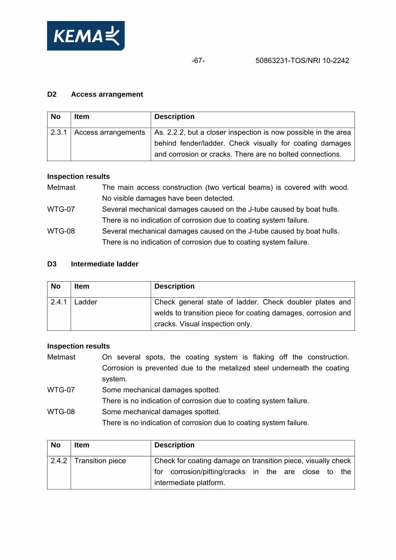
-67- 50863231-TOS/NRI 10-2242 D2 Access arrangement No Item Description
2.3.1 Access arrangements As. 2.2.2, but a closer inspection is now possible in the area behind fender/ladder. Check visually for coating damages and corrosion or cracks. There are no bolted connections.
Inspection results Metmast The main access construction (two vertical beams) is covered with wood.
No visible damages have been detected. WTG-07 Several mechanical damages caused on the J-tube caused by boat hulls.
There is no indication of corrosion due to coating system failure. WTG-08 Several mechanical damages caused on the J-tube caused by boat hulls.
There is no indication of corrosion due to coating system failure. D3 Intermediate ladder No Item Description
2.4.1 Ladder Check general state of ladder. Check doubler plates and welds to transition piece for coating damages, corrosion and cracks. Visual inspection only.
Inspection results Metmast On several spots, the coating system is flaking off the construction.
Corrosion is prevented due to the metalized steel underneath the coating system.
WTG-07 Some mechanical damages spotted. There is no indication of corrosion due to coating system failure.
WTG-08 Some mechanical damages spotted. There is no indication of corrosion due to coating system failure.
No Item Description
2.4.2 Transition piece Check for coating damage on transition piece, visually check for corrosion/pitting/cracks in the are close to the intermediate platform.
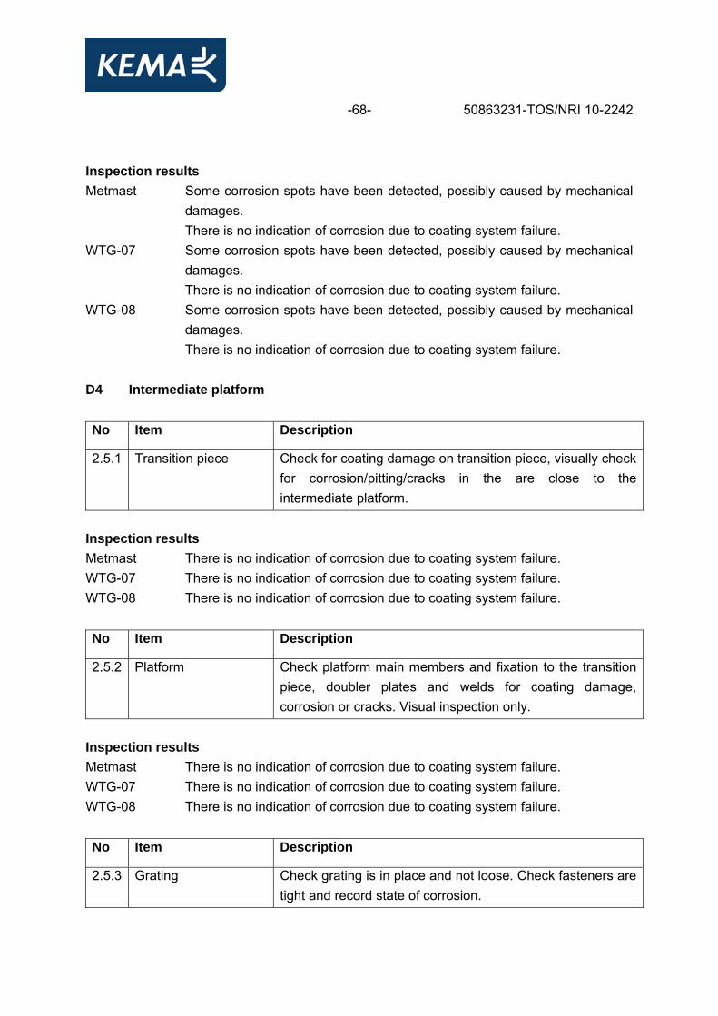
-68- 50863231-TOS/NRI 10-2242 Inspection results Metmast Some corrosion spots have been detected, possibly caused by mechanical
damages. There is no indication of corrosion due to coating system failure.
WTG-07 Some corrosion spots have been detected, possibly caused by mechanical damages. There is no indication of corrosion due to coating system failure.
WTG-08 Some corrosion spots have been detected, possibly caused by mechanical damages. There is no indication of corrosion due to coating system failure.
D4 Intermediate platform No Item Description
2.5.1 Transition piece Check for coating damage on transition piece, visually check for corrosion/pitting/cracks in the are close to the intermediate platform.
Inspection results Metmast There is no indication of corrosion due to coating system failure. WTG-07 There is no indication of corrosion due to coating system failure. WTG-08 There is no indication of corrosion due to coating system failure. No Item Description
2.5.2 Platform Check platform main members and fixation to the transition piece, doubler plates and welds for coating damage, corrosion or cracks. Visual inspection only.
Inspection results Metmast There is no indication of corrosion due to coating system failure. WTG-07 There is no indication of corrosion due to coating system failure. WTG-08 There is no indication of corrosion due to coating system failure. No Item Description
2.5.3 Grating Check grating is in place and not loose. Check fasteners are tight and record state of corrosion.

-69- 50863231-TOS/NRI 10-2242 Inspection results Metmast There is no indication of corrosion. WTG-07 Corrosion spotted on bolts under grating, possibly caused by galvanic
corrosion. WTG-08 Corrosion spotted on bolts under grating, possibly caused by galvanic
corrosion. No Item Description
2.5.4 Hand rail Check for integrity and that fixation to platform is intact.
Inspection results Metmast Some mechanical damage.
There is no indication of corrosion due to coating system failure. WTG-07 Some mechanical damage.
There is no indication of corrosion due to coating system failure. WTG-08 Some mechanical damage.
There is no indication of corrosion due to coating system failure.
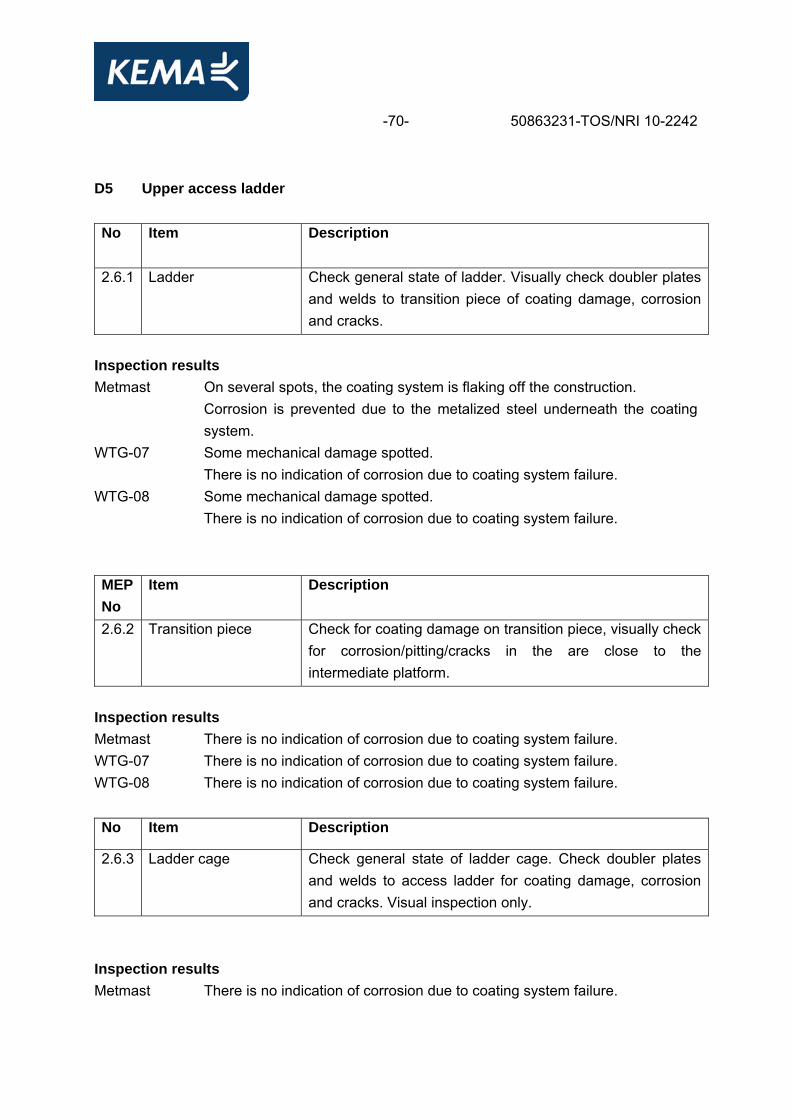
-70- 50863231-TOS/NRI 10-2242 D5 Upper access ladder No
Item
Description
2.6.1 Ladder Check general state of ladder. Visually check doubler plates and welds to transition piece of coating damage, corrosion and cracks.
Inspection results Metmast On several spots, the coating system is flaking off the construction.
Corrosion is prevented due to the metalized steel underneath the coating system.
WTG-07 Some mechanical damage spotted. There is no indication of corrosion due to coating system failure.
WTG-08 Some mechanical damage spotted. There is no indication of corrosion due to coating system failure.
MEP No
Item Description
2.6.2 Transition piece Check for coating damage on transition piece, visually check for corrosion/pitting/cracks in the are close to the intermediate platform.
Inspection results Metmast There is no indication of corrosion due to coating system failure. WTG-07 There is no indication of corrosion due to coating system failure. WTG-08 There is no indication of corrosion due to coating system failure. No Item Description
2.6.3 Ladder cage Check general state of ladder cage. Check doubler plates and welds to access ladder for coating damage, corrosion and cracks. Visual inspection only.
Inspection results Metmast There is no indication of corrosion due to coating system failure.
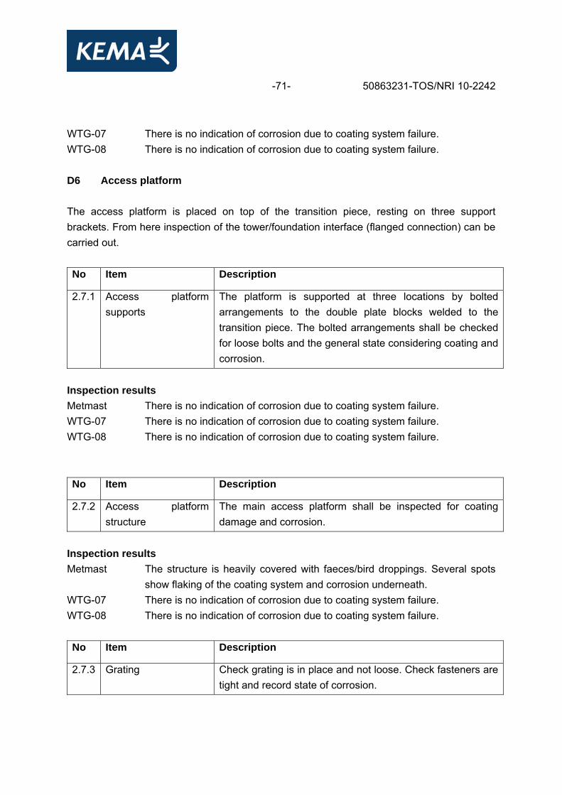
-71- 50863231-TOS/NRI 10-2242 WTG-07 There is no indication of corrosion due to coating system failure. WTG-08 There is no indication of corrosion due to coating system failure. D6 Access platform The access platform is placed on top of the transition piece, resting on three support brackets. From here inspection of the tower/foundation interface (flanged connection) can be carried out. No Item Description
2.7.1 Access platform supports
The platform is supported at three locations by bolted arrangements to the double plate blocks welded to the transition piece. The bolted arrangements shall be checked for loose bolts and the general state considering coating and corrosion.
Inspection results Metmast There is no indication of corrosion due to coating system failure. WTG-07 There is no indication of corrosion due to coating system failure. WTG-08 There is no indication of corrosion due to coating system failure. No Item Description
2.7.2 Access platform structure
The main access platform shall be inspected for coating damage and corrosion.
Inspection results Metmast The structure is heavily covered with faeces/bird droppings. Several spots
show flaking of the coating system and corrosion underneath. WTG-07 There is no indication of corrosion due to coating system failure. WTG-08 There is no indication of corrosion due to coating system failure. No Item Description
2.7.3 Grating Check grating is in place and not loose. Check fasteners are tight and record state of corrosion.
-72- 50863231-TOS/NRI 10-2242 Inspection results Metmast There is no indication of corrosion. WTG-07 There is no indication of corrosion. WTG-08 There is no indication of corrosion. No Item Description
2.7.4 Hand rail Check for integrity and that fixation to the platform is intact.
Inspection results Metmast The handrail is heavily covered with faeces/bird droppings. Several spots
show flaking of the coating system and corrosion underneath. WTG-07 The handrail shows several mechanical damages on the coating system,
especially near the Davit crane. There is no indication of corrosion due to coating system failure.
WTG-08 The handrail shows several mechanical damages on the coating system, especially near the Davit crane. There is no indication of corrosion due to coating system failure.
No Item Description
2.7.5 J-tubes and cables The top of the J-tubes and the cables hang-off arrangements shall be checked for general integrity and sign of damage recorded. Check cables are intact with no damages to the sheathing.
Inspection results Metmast There is no indication of corrosion due to coating system failure. WTG-07 There is no indication of corrosion due to coating system failure. WTG-08 There is no indication of corrosion due to coating system failure. No Item Description
2.7.6 Flange welds The external circumferential girth welds to the tower flanges connection to be inspected for corrosion and cracks, including the T-crossing with longitudinal weld. Visual inspection only.
-73- 50863231-TOS/NRI 10-2242 Inspection results Metmast There is no indication of corrosion due to coating system failure. WTG-07 There is no indication of corrosion due to coating system failure. WTG-08 There is no indication of corrosion due to coating system failure. No Item Description
2.7.7 Hatch Check hatch for corrosion damage and test functionality. Check hinges are in proper condition.
Inspection results Metmast There is no indication of corrosion due to coating system failure. WTG-07 There is no indication of corrosion due to coating system failure. WTG-08 There is no indication of corrosion due to coating system failure.
-74- 50863231-TOS/NRI 10-2242 APPENDIX VII INSPECTIONS 2009 D1 Inspections by boat The boat contoured the transition piece, during which the following items were inspected. No Item Description
2.2.1 Access Arrangements Check general state of exterior including ladder, fender. Check extent of marine growth.
Inspection results Metmast Marine growth is up tot several meters above water level, The fender is
wooden pile covering two vertical beams (no visible defects). There is no indication of corrosion due to coating system failure.
WTG-25 Marine growth is up to 1 meter above water level. No fender present. There is no indication of corrosion due to coating system failure.
No Item Description
2.2.2 J-tubes Check general state of J-tubes as allowed to distance.
Inspection results Metmast There are no J-tubes present. WTG-25 Several mechanical damages caused by boat hulls.
There is no indication of corrosion due to coating system failure. D2 Access arrangement No Item Description
2.3.1 Access arrangements As 2.2.2, but a closer inspection is now possible in the area behind fender/ladder. Check visually for coating damages and corrosion or cracks. There are no bolted connections.
Inspection results Metmast The main access construction (two vertical beams) is covered with wood.
No visible damages has been detected. WTG-25 Several mechanical damages caused on the J-tube caused by boat hulls.
-75- 50863231-TOS/NRI 10-2242
There is no indication of corrosion due to coating system failure. D3 Intermediate ladder No Item Description
2.4.1 Ladder Check general state of ladder. Check doubler plates and welds to transition piece for coating damages, corrosion and cracks. visually inspection only.
Inspection results Metmast On several spots, the coating system is flaking off the construction.
Corrosion is prevented due to the metalized steel underneath the coating system.
WTG-25 Some mechanical damages spotted. There is no indication of corrosion due to coating system failure.
No Item Description
2.4.2 Transition piece Check for coating damage on transition piece, visually check for corrosion/pitting/cracks in the are close to the intermediate platform.
Inspection results Metmast Some corrosion spots have been detected, possibly caused by mechanical
damages. There is no indication of corrosion due to coating system failure.
WTG-25 Some corrosion spots have been detected, possibly caused by mechanical damages. There is no indication of corrosion due to coating system failure.

-76- 50863231-TOS/NRI 10-2242 D4 Intermediate platform No Item Description
2.5.1 Transition piece Check for coating damage on transition piece, visually check for corrosion/pitting/cracks in the are close to the intermediate platform.
Inspection results Metmast There is no indication of corrosion due to coating system failure. WTG-25 There is no indication of corrosion due to coating system failure. No Item Description
2.5.2 Platform Check platform main members and fixation to the transition piece, doubler plates and welds for coating damage, corrosion or cracks. Visual inspection only.
Inspection results Metmast There is no indication of corrosion due to coating system failure.
WTG-25 There is no indication of corrosion due to coating system failure. No Item Description
2.5.3 Grating Check grating is in place and not loose. Check fasteners are tight and record state of corrosion.
Inspection results Metmast There is no indication of corrosion. WTG-25 Corrosion spotted on bolts under grating, possibly caused by galvanic
corrosion. MEP No
Item Description
2.5.4 Hand rail Check for integrity and that fixation to platform is intact.

-77- 50863231-TOS/NRI 10-2242 Inspection results Metmast Some mechanical damage.
There is no indication of corrosion due to coating system failure. WTG-25 Some mechanical damage.
There is no indication of corrosion due to coating system failure. D5 Upper access ladder No Item Description
2.6.1 Ladder Check general state of ladder. Visually check doubler plates and welds to transition piece of coating damage, corrosion and cracks.
Inspection results Metmast On several spots, the coating system is flaking off the construction.
Corrosion is prevented due to the metalized steel underneath the coating system.
WTG-25 Some mechanical damage spotted. There is no indication of corrosion due to coating system failure.
No Item Description
2.6.2 Transition piece Check for coating damage on transition piece, visually check for corrosion/pitting/cracks in the are close to the intermediate platform.
Inspection results Metmast There is no indication of corrosion due to coating system failure. WTG-25 There is no indication of corrosion due to coating system failure. No Item Description
2.6.3 Ladder cage Check general state of ladder cage. Check doubler plates and welds to access ladder for coating damage, corrosion and cracks. Visual inspection only.
Inspection results Metmast There is no indication of corrosion due to coating system failure. WTG-25 There is no indication of corrosion due to coating system failure.
-78- 50863231-TOS/NRI 10-2242 D6 Access platform The access platform is placed on top of the transition piece, resting on three support brackets. From here inspection of the tower/foundation interface (flanged connection) can be carried out. No Item Description
2.7.1 Access platform supports
The platform is supported at three locations by bolted arrangements to the double plate blocks welded to the transition piece. The bolted arrangements shall be checked for loose bolts and the general state considering coating and corrosion.
Inspection results Metmast There is no indication of corrosion due to coating system failure. WTG-25 There is no indication of corrosion due to coating system failure. No Item Description
2.7.2 Access platform structure
The main access platform shall be inspected for coating damage and corrosion.
Inspection results Metmast The structure is heavily covered with faeces/bird droppings. Several spots
show flaking of the coating system and corrosion underneath. WTG-25 There is no indication of corrosion due to coating system failure. No Item Description
2.7.3 Grating Check grating is in place and not loose. Check fasteners are tight and record state of corrosion.
Inspection results Metmast There is no indication of corrosion. WTG-25 There is no indication of corrosion. No Item Description
2.7.4 Hand rail Check for integrity and that fixation to the platform is intact.
-79- 50863231-TOS/NRI 10-2242 Inspection results Metmast The handrail is heavily covered with faeces/bird droppings. Several spots
show flaking of the coating system and corrosion underneath. WTG-25 The handrail shows several mechanical damages on the coating system,
especially near the Davit crane. There is no indication of corrosion due to coating system failure.
No Item Description
2.7.5 J-tubes and cables The top of the J-tubes and the cables hang-off arrangements shall be checked for general integrity and sign of damage recorded. Check cables are intact with no damages to the sheathing.
Inspection results Metmast There is no indication of corrosion due to coating system failure. WTG-25 There is no indication of corrosion due to coating system failure. No Item Description
2.7.6 Flange welds The external circumferential girth welds to the tower flanges connection to be inspected for corrosion and cracks, including the T-crossing with longitudinal weld. Visual inspection only.
Inspection results Metmast There is no indication of corrosion due to coating system failure. WTG-25 There is no indication of corrosion due to coating system failure. No Item Description
2.7.7 Hatch Check hatch for corrosion damage and test functionality. Check hinges are in proper condition.
Inspection results Metmast There is no indication of corrosion due to coating system failure. WTG-25 There is no indication of corrosion due to coating system failure.