adaptive process controls and ultrasonics for high
TRANSCRIPT
Adaptive Process Controls and Ultrasonics for High
Temperature PEM MEA ManufactureRaymond Puffer
Center for Automation Technologies and Systems (CATS)Rensselaer Polytechnic Institute
12 May 2011 MN005
This presentation does not contain any proprietary, confidential, or otherwise restricted information

2
• Project start date: 9/01/08• Project end date: 6/30/12• Percent complete: 70%
• A. Lack of High-Volume Membrane Electrode Assembly (MEA) Production
• F. Low Levels of Quality Control and Inflexible Processes
• Total project funding: $2,479,908– DOE share: $1,611,129– Contractor share: $868,779
• Funding received in FY10: $400,000
• Funding for FY11: $300,000
Timeline
Budget
Barriers Addressed
• RPI CATS- Project Lead• ASU- Subcontractor• BASF Fuel Cell- Collaborator• PMD- Collaborator• UltraCell- Collaborator• NREL- Collaborator• Ballard- Collaborator
Partners
Overview
3
• Situation: In spite of the fact that there are variations in MEA component material properties, we use the same manufacturing process parameters. This results in variations in MEA properties and performance, and the potential for stack failures and re-work, and reduced durability.
• We need to develop a deeper understanding of the relationships among MEA material properties, manufacturing processes parameters, and MEA performance (3Ps).
• The high level objective of the proposed work is to enable cost effective, high volume manufacture of high temperature (160-180oC) PEM MEAs by:
Relevance (1)Situation and Objectives

4
• (1) achieving greater uniformity and performance of high-temperature MEAs by the application of adaptive real-time process controls (APC) combined with effective in-situ property sensing to the MEA pressing process.– This objective addresses Barrier F, Low Levels of Quality Control
and Inflexible Processes• (2) greatly reducing MEA pressing cycle time through the
development of novel, robust ultrasonic (U/S) bonding processes for high temperature (160-180oC) PEM MEAs. – This objective addresses Barrier A, Lack of High-Volume
Membrane Electrode Assembly (MEA) Production• This year we have focused on process optimization
studies, APC implementation for thermal pressing, initial stack testing, and LTPEM U/S pressing tests.
Relevance (2)Situation and Objectives

Summary of 2010 Review• U/S sealing of high temperature (HT) MEAs showed:
– Performance equal to or better than BASF specs– Reduced activation losses– Excellent durability – > 90% cycle time reduction– > 95% energy savings
• Initial investigation of in-situ sensing of complex impedance for thermal pressing showed promise
• Preliminary thermal models of both U/S and thermal processes were presented
• Promising initial results of U/S sealing of LT MEAs.• Phase I cost analysis showed potential for
significant cost reductions from both ultrasonics (83.7%) and APC (37.9%)

6
Technical Approach (1)Project Plan
Baseline current process and CostsThermal PressingUltrasonic Pressing
2 Stage Design of Experiments Cell Level
Testing
Modeling 3PsIn-Situ Sensing Methodologies
Controller Design
Phase I
Cell Level Testing
Controller Implementation on Commercial Press
Model Refinement and Validation
Phase II
Update Cost Analysis
Phase III Refinement of APC Techniques
Cell & Stack Level Testing
Update Cost Analysis
Publish APC Design Guide
Initiate Stack TestingU/S Process Optimization
Investigate U/S for LT PEM MEAs

Technical Approach (2)Phase II APC
• Design and construct new commercial thermal press tooling to incorporate sensor(s) and electrically isolate tooling.
• Investigate various sensing modes.• Modification of press controls for real-
time APC using AC impedance.• Conduct designed experiments with range of GDE
and membrane material properties to identify characteristic material response.
• Evaluation of APC MEA performance compared to baseline MEAs, first in single cells and later in stacks.
• Compare variability in performance of APC MEAs to baseline MEAs
• Refinement of process models and control algorithms.

Technical Approach (3)Phase II Ultrasonic Sealing
• Ultrasonic sealing process optimization via DoE.• Durability testing of U/S sealed MEAs.• Experimentation on U/S sealing of large size
MEAs.– Requires custom tooling and significant press re-
design.• Investigate in-situ sensing techniques for APC,
compatible with process cycle time.• Conduct DoE for use of U/S for sealing of low
temperature MEAs.• Stack level testing of U/S sealed MEAs and
compare performance variability to baseline thermal pressed MEAs.
• Fully instrumented 10 cell stack (T, v for each cell), with use of current interrupt tests for GDL performance. Can vary compression.

9
Technical Approach (4)Investigation of U/S for LTPEM MEAs
• Task added for Phase II.• Initial tests of U/S sealed LTPEM MEAs promising, but we
require baseline data and further investigation• Ballard Power Systems, Inc. has agreed to partner with
us for this investigation– Supply standard anodes, cathodes, and membrane for study– Provide baseline MEA performance data– Advise on testing protocol
• CATS will conduct designed experiment to establish optimum U/S process parameters
• NREL will supplement CATS testing capability and validate results

10
Approach/Milestones
Month/Year Milestone or Go/No-Go decision
November, 2009 Phase I Go/No-Go Decision will be based on an initial cost analysis showing substantial reductions in PBI type MEA manufacturing costs based on the ultrasonic sealing/welding and/or in-situ adaptive process controls. Note: A Go decision was made by DOE to move into Phase II.
June, 2011 Phase II Milestone: Demonstrate the ability of APC and Ultrasonics to improve the performance and uniformity of MEAs.Go/No-Go Decision: Ability to meet target cost reductions.
June, 2012 Phase III Milestone: Analysis of benefits of APC and ultrasonics. Validation of cost analysis. Target for improvement to MEA durability is 15%, target reduction of MEA manufacturing cost for pressing is 25% for the use of APC with thermal pressing and 75% for U/S sealing.

Technical Accomplishments (1)APC
• Down stream process (stack assembly) benefits of APC.• Potential to improve MEA uniformity and reduce process cycle time.• Potential use as screening tool prior to stack assembly. • In-situ AC Impedance measurement• Phase I results not conclusive re: correlation of impedance and phase
angle with performance• Hypothesis: when dZ/dt=0, an electrochemical cell has been formed• Resulting MEAs exceed specifications• Less activation loss• Reduced cycle time
Magnitude of Impedance vs Time During MEA Pressing540um Membrane, 1KHz, S/N 2122
0
0.05
0.1
0.15
0.2
0.25
0.3
15000 20000 25000 30000 35000 40000
Time (milliseconds)
Mag
nitu
de o
f Com
plex
Impe
danc
e (o
hms)
Phase Angle of Impedance vs Time During MEA Pressing540um Membrane, 1KHz, S/N 2131
-100
-80
-60
-40
-20
0
20
15000 25000 35000 45000 55000
Time (milliseconds)
Phas
e A
ngle
(deg
rees
)
Magnitude of Impedance vs Timezoomed out
0
5000
10000
15000
20000
25000
30000
35000
40000
42:17.3 42:25.9 42:34.6 42:43.2 42:51.8 43:00.5 43:09.1
Time
Impe
danc
e (m
illio
hms)
2187
Phase I Plots Phase II Plot

Technical Accomplishments (2)APC
0
0.1
0.2
0.3
0.4
0.5
0.6
0.7
0.8
0.9
1
0 0.2 0.4 0.6 0.8 1 1.2
Volta
ge (V
)
Current Density (A/cm2)
Representative APC-produced HT PEM MEA. Active area 45.15cm2, H2/air, stoic 1.2/2.0, 160oC
2195
Spec
• Non-optimized APC pressed MEA exceeded BASF specifications
• Significant cycle time reduction• Need for process optimization study• Study of performance variation in stack
12

Spe cific
A
im s
• Design of Experiments #1
• Design of Experiments #2
• Designed experiments to determine best combination of process parameters
• Will need to repeat experiments for different size MEAs
• Confirm durability
Technical Accomplishments (3)Optimization of Ultrasonic Sealing
Factors Factor Values
Low High
Energy Flux (J/mm2) 0.4 0.6
Sealing Pressure (N/mm2) 0.44 0.88
Amplitude Booster 1.5x 2.5x
Anvil Support Backer Stiffness 90A Urethane Steel
Heat Treatment No Yes
Factors Factor Values
High Low Medium
Membrane Thickness (mm) 0.360 0.300
Anvil Support Backer Stiffness Polycarbonate 90A Urethane
Sealing Pressure (N/mm2) 0.66 0.22 0.44
Energy Flux (J/mm2) 0.4 0.2

Spe
cific
Aim
s
• All MEAs exceeded BASF specs• Improved activation over-potential• Note: slope of activation region confirmed due to test
hardware resistance
Technical Accomplishments (4)Optimization of Ultrasonic Sealing
0.00.10.20.30.40.50.60.70.80.91.0
0 0.2 0.4 0.6 0.8 1 1.2
Volta
ge (V
)
Current Density (A/cm2)
DoE #2 Optimal vs. BASF Specification-
Active area 45.15cm2, H2/air, stoic 1.2/2.0, 160oC
DoE #2 Optimal
BASF Specification

Spe
cific
Aim
s
• Numerical analysis modeling of heat flux distribution in MEA during ultrasonic sealing
• 3 Layered Model of MEA
• Heat Generated from Dampers as
• Spectrograph of FFT vs. Time for velocity decay to determine velocity differences in Eqn 1
Technical Accomplishments (5)Modeling
Eqn. 1A
mpl
itude
of V
eloc
ity D
iffer
ence
s
Spe
cific
Aim
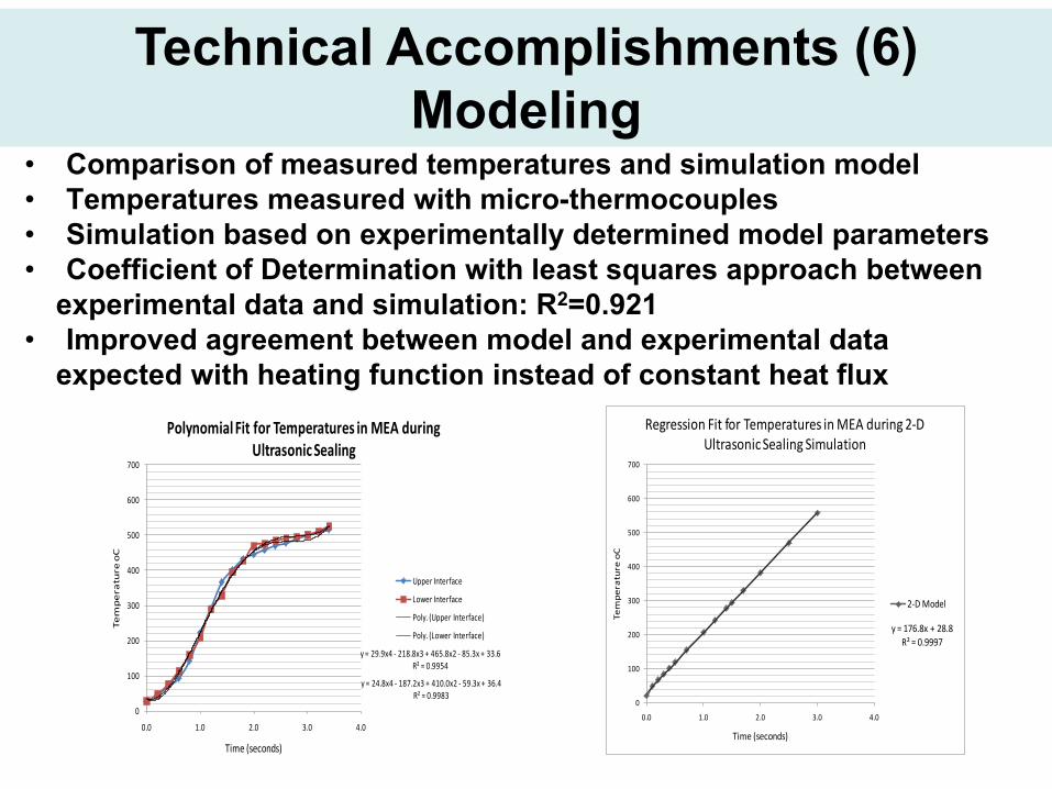
s• Comparison of measured temperatures and simulation model• Temperatures measured with micro-thermocouples • Simulation based on experimentally determined model parameters• Coefficient of Determination with least squares approach between
experimental data and simulation: R2=0.921• Improved agreement between model and experimental data
expected with heating function instead of constant heat flux
Technical Accomplishments (6)Modeling
y = 29.9x4 - 218.8x3 + 465.8x2 - 85.3x + 33.6R² = 0.9954
y = 24.8x4 - 187.2x3 + 410.0x2 - 59.3x + 36.4R² = 0.9983
0
100
200
300
400
500
600
700
0.0 1.0 2.0 3.0 4.0
Tem
pe
ratu
reo
C
Time (seconds)
Polynomial Fit for Temperatures in MEA during Ultrasonic Sealing
Upper Interface
Lower Interface
Poly. (Upper Interface)
Poly. (Lower Interface)y = 176.8x + 28.8
R² = 0.9997
0
100
200
300
400
500
600
700
0.0 1.0 2.0 3.0 4.0
Tem
pe
ratu
re o
C
Time (seconds)
Regression Fit for Temperatures in MEA during 2-D Ultrasonic Sealing Simulation
2-D Model
17
Technical Accomplishments (7) Phase II Manufacturing Cost Analysis
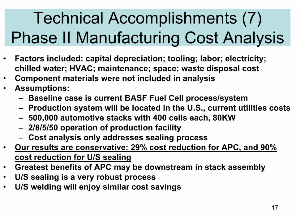
• Factors included: capital depreciation; tooling; labor; electricity; chilled water; HVAC; maintenance; space; waste disposal cost
• Component materials were not included in analysis• Assumptions:
– Baseline case is current BASF Fuel Cell process/system– Production system will be located in the U.S., current utilities costs– 500,000 automotive stacks with 400 cells each, 80KW– 2/8/5/50 operation of production facility– Cost analysis only addresses sealing process
• Our results are conservative: 29% cost reduction for APC, and 90% cost reduction for U/S sealing
• Greatest benefits of APC may be downstream in stack assembly• U/S sealing is a very robust process• U/S welding will enjoy similar cost savings

18
Collaborations• Sub-contractor
– Arizona State University (Academic): application of EIS
• Partners– BASF Fuel Cell (Industry): HT PEM MEA expertise – Progressive Machine and Design (Industry): expertise in industrial
controls and MEA manufacturing systems design.– UltraCell (Industry): fuel cell system manufacturer, evaluate APC stack
performance– Ballard Power Systems (Industry): supplier of LTPEM stacks, support
investigations into the use of ultrasonics for LTPEM MEA pressing– National Renewable Energy Laboratory (Government Lab): low
temperature MEA testing, independent validation of low temperature test results.

19
Proposed Future Work • Phase II
– U/S sealing of larger MEAs– U/S MEA durability testing– LT MEA U/S sealing designed experiments– MEA performance evaluation (single cell)– Model refinement and validation– Continued stack level testing– Phase II program review
• Phase III– Refine APC techniques– Model refinement– APC evaluation, single cell and short stacks– Develop design guidelines based on lessons learned– Update manufacturing cost analysis– Phase III program review

20
• Relevance: The proposed research addresses two critical barriers.– The critical need for high volume MEA manufacturing processes, and– The need for QC methods and process flexibility.– Additional ultrasonic sealing investigations for low temperature MEAs
• Approach:– Develop and apply adaptive, real time, process controls to improve performance
and uniformity of HT PEM MEAs– Novel ultrasonic bonding methods to achieve significant productivity increases
• Collaborations: Strong team of RPI, ASU, BASF Fuel Cell, PMD, UltraCell, Ballard and NREL with expertise in all critical elements of HT and LT PEM fuel cell technologies.
• Technical Accomplishments/status: Demonstrated benefits of U/S sealing; modeling of processes; encouraging APC results; significant cost savings projected.
• Proposed Future Research: Continue development of process and control models; implement and validate APC via cell and stack testing; U/S durability testing; U/S larger size MEAs; update cost models; LT U/S sealing investigation.
Project Summary

21
Technical Back-up Slides

Typical HT PEM MEA Design & PBI Membrane

Details of Phase II Manufacturing Cost Analysis
Cost Element Current Technology APC UltrasonicsCapital Depreciation $.0896 $.0637 $.0055Tooling $.0608 $.0432 $.0245Labor $.1158 $.0823 $.0092Electricity $.0579 $.0412 $.0001Chilled Water $.0293 $.0208 $.0003HVAC $.0009 $.0007 $.0000Maintenance $.0362 $.0257 $.0012Space $.0041 $.0029 $.0003Disposal $.0896 $.0637 $.0066Cost per MEA $.4841 $.3443 $.0477Cost per KW $1.9366 $1.3770 $0.1908Percent Reduction -- 28.89% 90.15%