addendum no. 1 date: july 28, 2015 owner: university · pdf filea. standard: asme b40.200. b....
TRANSCRIPT
IFB 9783 (Addendum #1)
ADDENDUM NO. 1 DATE: July 28, 2015
TO: ALL BIDDERS
OWNER: University of Central Missouri (UCM)
Department of Procurement & Materials Management
Southeast Complex Building A
415 East Clark Street
Warrensburg, MO 64093
SUBJECT: Addendum #1 for IFB 9783 (UCM Greenwood Community Building Project)
_____________________________________________________________________________
THIS ADDENDUM IS ISSUED AS PART OF THE BID DOCUMENTS FOR THIS BID AND AMENDS ONLY
THOSE ITEMS SPECIFICALLY DEFINED HEREIN. PLEASE ACKNOWLEDGE THE RECEIPT OF THIS
ADDENDUM ON THE ATTACHMENT A – BID FORM.
______________________________________________________________________________
This addendum forms a part of the Bid Documents and modifies the Bidding Documents dated July 22, 2015 with
clarification noted below.
In preparing bids, the Bidder shall take into consideration the following items. Information shown herein supersedes
requirements issued under previous date.
Clarification:
Clarify: I saw this project on the Builders Association Planroom. The specification Table of Contents
lists Division 22 and Division 23. But the document package I downloaded from your site jumps
from Division 12 to Division 31. Please advise.
Response: Include the following:

UNIVERSITY OF CENTRAL MISSOURI GREENWOOD COMMUNITY BUILDING ISSUED FOR BID SUBMISSION
SLEEVES AND SLEEVE SEALS FOR PLUMBING PIPING 220517 - 1
SECTION 220517 - SLEEVES AND SLEEVE SEALS FOR PLUMBING PIPING
PART 1 - GENERAL
1.1 SUMMARY
A. Section Includes:
1. Sleeves. 2. Sleeve-seal systems. 3. Grout.
PART 2 - PRODUCTS
2.1 SLEEVES
A. Cast-Iron Wall Pipes: Cast or fabricated of cast or ductile iron and equivalent to ductile-iron pressure pipe, with plain ends and integral waterstop unless otherwise indicated.
B. Galvanized-Steel Wall Pipes: ASTM A 53/A 53M, Schedule 40, with plain ends and welded steel collar; zinc coated.
C. Galvanized-Steel-Pipe Sleeves: ASTM A 53/A 53M, Type E, Grade B, Schedule 40, zinc coated, with plain ends.
D. PVC-Pipe Sleeves: ASTM D 1785, Schedule 40.
E. Galvanized-Steel-Sheet Sleeves: 0.0239-inch (0.6-mm) minimum thickness; round tube closed with welded longitudinal joint.
2.2 SLEEVE-SEAL SYSTEMS
A. Description: Modular sealing-element unit, designed for field assembly, for filling annular space between piping and sleeve.
1. Sealing Elements: EPDM-rubber or NBR interlocking links shaped to fit surface of pipe. Include type and number required for pipe material and size of pipe.
2. Pressure Plates: Stainless steel. 3. Connecting Bolts and Nuts: Stainless steel of length required to secure pressure plates to
sealing elements.
2.3 GROUT
A. Standard: ASTM C 1107/C 1107M, Grade B, post-hardening and volume-adjusting, dry, hydraulic-cement grout.
B. Characteristics: Nonshrink; recommended for interior and exterior applications.

UNIVERSITY OF CENTRAL MISSOURI GREENWOOD COMMUNITY BUILDING ISSUED FOR BID SUBMISSION
SLEEVES AND SLEEVE SEALS FOR PLUMBING PIPING 220517 - 2
C. Design Mix: 5000-psi (34.5-MPa), 28-day compressive strength.
D. Packaging: Premixed and factory packaged.
PART 3 - EXECUTION
3.1 SLEEVE INSTALLATION
A. Install sleeves for piping passing through penetrations in floors, partitions, roofs, and walls.
B. For sleeves that will have sleeve-seal system installed, select sleeves of size large enough to provide 1-inch (25-mm) annular clear space between piping and concrete slabs and walls. 1. Sleeves are not required for core-drilled holes.
C. Install sleeves in concrete floors, concrete roof slabs, and concrete walls as new slabs and walls are constructed.
1. Cut sleeves to length for mounting flush with both surfaces.
a. Exception: Extend sleeves installed in floors of mechanical equipment areas or other wet areas 2 inches (50 mm) above finished floor level.
2. Using grout, seal the space outside of sleeves in slabs and walls without sleeve-seal system.
D. Install sleeves for pipes passing through interior partitions.
1. Cut sleeves to length for mounting flush with both surfaces. 2. Install sleeves that are large enough to provide 1/4-inch (6.4-mm) annular clear space
between sleeve and pipe or pipe insulation. 3. Seal annular space between sleeve and piping or piping insulation; use joint sealants
appropriate for size, depth, and location of joint. Comply with requirements for sealants specified in Section 079200 "Joint Sealants."
E. Fire-Barrier Penetrations: Maintain indicated fire rating of walls, partitions, ceilings, and floors at pipe penetrations. Seal pipe penetrations with firestop materials. Comply with requirements for firestopping specified in Section 078413 "Penetration Firestopping."
3.2 SLEEVE-SEAL-SYSTEM INSTALLATION
A. Install sleeve-seal systems in sleeves in exterior concrete walls and slabs-on-grade at service piping entries into building.
B. Select type, size, and number of sealing elements required for piping material and size and for sleeve ID or hole size. Position piping in center of sleeve. Center piping in penetration, assemble sleeve-seal system components, and install in annular space between piping and sleeve. Tighten bolts against pressure plates that cause sealing elements to expand and make a watertight seal.

UNIVERSITY OF CENTRAL MISSOURI GREENWOOD COMMUNITY BUILDING ISSUED FOR BID SUBMISSION
SLEEVES AND SLEEVE SEALS FOR PLUMBING PIPING 220517 - 3
3.3 SLEEVE AND SLEEVE-SEAL SCHEDULE
A. Use sleeves and sleeve seals for the following piping-penetration applications:
1. Exterior Concrete Walls above Grade:
a. Cast-iron wall sleeves, Galvanized-steel wall sleeves or Galvanized-steel-pipe sleeves.
2. Exterior Concrete Walls below Grade:
a. Cast-iron wall sleeves with sleeve-seal system, Galvanized-steel wall sleeves with sleeve-seal system or Galvanized-steel-pipe sleeves with sleeve-seal system.
1) Select sleeve size to allow for 1-inch (25-mm) annular clear space between piping and sleeve for installing sleeve-seal system.
3. Concrete Slabs-on-Grade:
a. Cast-iron wall sleeves with sleeve-seal system, Galvanized-steel wall sleeves with sleeve-seal system, or Galvanized-steel-pipe sleeves with sleeve-seal system.
1) Select sleeve size to allow for 1-inch (25-mm) annular clear space between piping and sleeve for installing sleeve-seal system.
4. Concrete Slabs above Grade:
a. Galvanized-steel-pipe sleeves.
5. Interior Partitions:
a. Galvanized-steel-pipe sleeves.
END OF SECTION 220517

UNIVERSITY OF CENTRAL MISSOURI GREENWOOD COMMUNITY BUILDING ISSUED FOR BID SUBMISSION
ESCUTCHEONS FOR PLUMBING PIPING 220518 - 1
SECTION 220518 - ESCUTCHEONS FOR PLUMBING PIPING
PART 1 - GENERAL
1.1 SUMMARY
A. Section Includes:
1. Escutcheons. 2. Floor plates.
1.2 ACTION SUBMITTALS
A. Product Data: For each type of product indicated.
PART 2 - PRODUCTS
2.1 ESCUTCHEONS
A. One-Piece, Cast-Brass Type: With polished, chrome-plated rough-brass finish and setscrew fastener.
B. One-Piece, Deep-Pattern Type: Deep-drawn, box-shaped brass with chrome-plated finish and spring-clip fasteners.
C. One-Piece, Stamped-Steel Type: With chrome-plated finish and spring-clip fasteners.
2.2 FLOOR PLATES
A. One-Piece Floor Plates: Cast-iron flange with holes for fasteners.
PART 3 - EXECUTION
3.1 INSTALLATION
A. Install escutcheons for piping penetrations of walls, ceilings, and finished floors.
B. Install escutcheons with ID to closely fit around pipe, tube, and insulation of piping and with OD that completely covers opening.
1. Escutcheons for New Piping: a. Piping with Fitting or Sleeve Protruding from Wall: One-piece, deep-pattern type. b. Chrome-Plated Piping: One-piece, cast-brass type with polished, chrome-plated
finish. c. Insulated Piping: One-piece, stamped-steel type.

UNIVERSITY OF CENTRAL MISSOURI GREENWOOD COMMUNITY BUILDING ISSUED FOR BID SUBMISSION
ESCUTCHEONS FOR PLUMBING PIPING 220518 - 2
d. Bare Piping at Wall and Floor Penetrations in Finished Spaces: One-piece, cast-brass type with polished, chrome-plated finish.
e. Bare Piping at Wall and Floor Penetrations in Finished Spaces: One-piece, stamped-steel type.
f. Bare Piping at Ceiling Penetrations in Finished Spaces: One-piece, cast-brass type with polished, chrome-plated finish.
g. Bare Piping at Ceiling Penetrations in Finished Spaces: One-piece, stamped-steel type.
h. Bare Piping in Unfinished Service Spaces: One-piece, cast-brass type with polished, chrome-plated or rough-brass finish.
i. Bare Piping in Unfinished Service Spaces: One-piece, stamped-steel type. j. Bare Piping in Equipment Rooms: One-piece, cast-brass type with polished,
chrome-plated or rough-brass finish. k. Bare Piping in Equipment Rooms: One-piece, stamped-steel type.
C. Install floor plates for piping penetrations of equipment-room floors.
D. Install floor plates with ID to closely fit around pipe, tube, and insulation of piping and with OD that completely covers opening.
1. New Piping: One-piece, floor-plate type.
3.2 FIELD QUALITY CONTROL
A. Replace broken and damaged escutcheons and floor plates using new materials.
END OF SECTION 220518
UNIVERSITY OF CENTRAL MISSOURI GREENWOOD COMMUNITY BUILDING ISSUED FOR BID SUBMISSION
METERS AND GAGES FOR PLUMBING PIPING 220519 - 1
SECTION 220519 - METERS AND GAGES FOR PLUMBING PIPING
PART 1 - GENERAL
1.1 SUMMARY
A. Section Includes:
1. Bimetallic-actuated thermometers. 2. Liquid-in-glass thermometers. 3. Thermowells. 4. Dial-type pressure gages. 5. Gage attachments.
1.2 SUBMITTALS
A. Product Data: thermometers and pressure gages
B. Product certificates.
C. Operation and maintenance data.
PART 2 - PRODUCTS
2.1 BIMETALLIC-ACTUATED THERMOMETERS
A. Standard: ASME B40.200.
B. Case: Liquid-filled and sealed type(s); stainless steel with 3-inch nominal diameter.
C. Dial: Nonreflective aluminum with permanently etched scale markings and scales in deg F and deg C.
D. Connector Type(s): Union joint, adjustable angle, with unified-inch screw threads.
E. Connector Size: 1/2 inch, with ASME B1.1 screw threads.
F. Stem: 0.25 or 0.375 inch in diameter; stainless steel.
G. Window: Plain glass.
H. Ring: Stainless steel.
I. Element: Bimetal coil.
J. Pointer: Dark-colored metal.
K. Accuracy: Plus or minus 1 percent of scale range.

UNIVERSITY OF CENTRAL MISSOURI GREENWOOD COMMUNITY BUILDING ISSUED FOR BID SUBMISSION
METERS AND GAGES FOR PLUMBING PIPING 220519 - 2
2.2 LIQUID-IN-GLASS THERMOMETERS
A. Metal-Case, Industrial-Style, Liquid-in-Glass Thermometers:
1. Standard: ASME B40.200. 2. Case: Cast aluminum; 7-inch nominal size unless otherwise indicated. 3. Case Form: Adjustable angle unless otherwise indicated. 4. Tube: Glass with magnifying lens and blue or red organic liquid. 5. Tube Background: Nonreflective aluminum with permanently etched scale markings
graduated in deg F and deg C. 6. Window: Glass. 7. Stem: Aluminum and of length to suit installation.
a. Design for Thermowell Installation: Bare stem. 8. Connector: 1-1/4 inches (32 mm), with ASME B1.1 screw threads. 9. Accuracy: Plus or minus 1 percent of scale range or one scale division, to a maximum of
1.5 percent of scale range.
B. Plastic-Case, Industrial-Style, Liquid-in-Glass Thermometers:
1. Standard: ASME B40.200. 2. Case: Plastic; 7-inch nominal size unless otherwise indicated. 3. Case Form: Adjustable angle unless otherwise indicated. 4. Tube: Glass with magnifying lens and blue or red organic liquid. 5. Tube Background: Nonreflective aluminum with permanently etched scale markings
graduated in deg F and deg C. 6. Window: Glass. 7. Stem: Aluminum, brass, or stainless steel and of length to suit installation.
a. Design for Thermowell Installation: Bare stem. 8. Connector: 1-1/4 inches, with ASME B1.1 screw threads. 9. Accuracy: Plus or minus 1 percent of scale range or one scale division, to a maximum of
1.5 percent of scale range.
2.3 THERMOWELLS
A. Thermowells:
1. Standard: ASME B40.200. 2. Description: Pressure-tight, socket-type fitting made for insertion into piping tee fitting. 3. Material for Use with Copper Tubing: CNR or CUNI. 4. Material for Use with Steel Piping: CRES or CSA. 5. Type: Stepped shank unless straight or tapered shank is indicated. 6. External Threads: NPS 1/2, NPS 3/4, or NPS 1, ASME B1.20.1 pipe threads. 7. Internal Threads: 1/2, 3/4, and 1 inch with ASME B1.1 screw threads. 8. Bore: Diameter required to match thermometer bulb or stem. 9. Insertion Length: Length required to match thermometer bulb or stem. 10. Lagging Extension: Include on thermowells for insulated piping and tubing. 11. Bushings: For converting size of thermowell's internal screw thread to size of
thermometer connection.
B. Heat-Transfer Medium: Mixture of graphite and glycerin.

UNIVERSITY OF CENTRAL MISSOURI GREENWOOD COMMUNITY BUILDING ISSUED FOR BID SUBMISSION
METERS AND GAGES FOR PLUMBING PIPING 220519 - 3
2.4 PRESSURE GAGES
A. Direct-Mounted, Metal-Case, Dial-Type Pressure Gages:
1. Standard: ASME B40.100. 2. Case: Liquid-filled or Sealed; cast aluminum or drawn steel;4-1/2-inch nominal diameter. 3. Pressure-Element Assembly: Bourdon tube unless otherwise indicated. 4. Pressure Connection: Brass, with NPS 1/4 or NPS 1/2, ASME B1.20.1 pipe threads and
bottom-outlet type unless back-outlet type is indicated. 5. Movement: Mechanical, with link to pressure element and connection to pointer. 6. Dial: Nonreflective aluminum with permanently etched scale markings graduated in psi
and kPa. 7. Pointer: Dark-colored metal. 8. Window: Glass. 9. Ring: Stainless steel. 10. Accuracy: Grade B, plus or minus 2 percent of middle half of scale range.
2.5 GAGE ATTACHMENTS
A. Snubbers: ASME B40.100, brass; with NPS 1/4 or NPS 1/2, ASME B1.20.1 pipe threads and piston-type surge-dampening device. Include extension for use on insulated piping.
B. Valves: brass ball or stainless-steel needle, with NPS 1/4 or NPS 1/2, ASME B1.20.1 pipe threads.
PART 3 - EXECUTION
3.1 INSTALLATION
A. Install thermowells with socket extending a minimum of 2 inches into fluid or to center of pipe as applicable and in vertical position in piping tees.
B. Install thermowells of sizes required to match thermometer connectors. Include bushings if required to match sizes.
C. Install thermowells with extension on insulated piping.
D. Fill thermowells with heat-transfer medium.
E. Install direct-mounted thermometers in thermowells and adjust vertical and tilted positions.
F. Install direct-mounted pressure gages in piping tees with pressure gage located on pipe at the most readable position.
G. Install valve and snubber in piping for each pressure gage for fluids.
H. Install thermometers in the following locations: 1. Inlet and outlet of each water heater.
I. Install pressure gages in the following locations: 1. Building water service entrance into building.

UNIVERSITY OF CENTRAL MISSOURI GREENWOOD COMMUNITY BUILDING ISSUED FOR BID SUBMISSION
METERS AND GAGES FOR PLUMBING PIPING 220519 - 4
J. Install meters and gages adjacent to machines and equipment to allow service and maintenance of meters, gages, machines, and equipment.
K. Adjust faces of meters and gages to proper angle for best visibility.
3.2 THERMOMETER SCHEDULE
A. Thermometers at inlet and outlet of each domestic water heater shall be one of the following:
1. Liquid-filled or Sealed, bimetallic-actuated type. 2. Industrial-style, liquid-in-glass type.
B. Thermometer stems shall be of length to match thermowell insertion length.
3.3 THERMOMETER SCALE-RANGE SCHEDULE
A. Scale Range for Domestic Cold-Water Piping: 0 to 150 deg F and minus 20 to plus 70 deg C.
B. Scale Range for Domestic Hot-Water Piping: 0 to 250 deg F and 0 to 150 deg C.
3.4 PRESSURE-GAGE SCHEDULE
A. Pressure gages at discharge of each water service into building shall be the following:
1. Liquid-filled or Sealed direct-mounted, metal case.
3.5 PRESSURE-GAGE SCALE-RANGE SCHEDULE
A. Scale Range for Water Service Piping: 0 to 100 psi and 0 to 600 kPa.
END OF SECTION 220519
UNIVERSITY OF CENTRAL MISSOURI GREENWOOD COMMUNITY BUILDING ISSUED FOR BID SUBMISSION
GENERAL-DUTY VALVES FOR PLUMBING PIPING 220523 - 1
SECTION 220523 - GENERAL-DUTY VALVES FOR PLUMBING PIPING
PART 1 - GENERAL
1.1 SUMMARY
A. Section Includes:
1. Brass ball valves. 2. Bronze ball valves. 3. Bronze globe valves.
1.2 SUBMITTALS
A. Product Data: For each type of valve indicated.
1.3 QUALITY ASSURANCE
A. ASME Compliance: ASME B16.10 and ASME B16.34 for ferrous valve dimensions and design criteria.
B. NSF Compliance: NSF 61 for valve materials for potable-water service.
PART 2 - PRODUCTS
2.1 GENERAL REQUIREMENTS FOR VALVES
A. Refer to valve schedule articles for applications of valves.
B. Valve Pressure and Temperature Ratings: Not less than indicated and as required for system pressures and temperatures.
C. Valve Sizes: Same as upstream piping unless otherwise indicated.
D. Valve Actuator Types:
1. Handlever: For quarter-turn valves NPS 6 (DN 150) and smaller.
E. Valves in Insulated Piping: With 2-inch (50-mm) stem extensions and the following features:
1. Ball Valves: With extended operating handle of non-thermal-conductive material, and protective sleeve that allows operation of valve without breaking the vapor seal or disturbing insulation.
F. Valve-End Connections:
1. Solder Joint: With sockets according to ASME B16.18.

UNIVERSITY OF CENTRAL MISSOURI GREENWOOD COMMUNITY BUILDING ISSUED FOR BID SUBMISSION
GENERAL-DUTY VALVES FOR PLUMBING PIPING 220523 - 2
2. Threaded: With threads according to ASME B1.20.1.
2.2 BRASS BALL VALVES
A. Two-Piece, Full-Port, Brass Ball Valves with Brass Trim:
1. Description:
a. Standard: MSS SP-110. b. SWP Rating: 150 psig (1035 kPa). c. CWP Rating: 600 psig (4140 kPa). d. Body Design: Two piece. e. Body Material: Forged brass. f. Ends: Threaded. g. Seats: PTFE or TFE. h. Stem: Brass. i. Ball: Chrome-plated brass. j. Port: Full.
B. Two-Piece, Regular-Port, Brass Ball Valves with Brass Trim:
1. Description:
a. Standard: MSS SP-110. b. SWP Rating: 150 psig (1035 kPa). c. CWP Rating: 600 psig (4140 kPa). d. Body Design: Two piece. e. Body Material: Forged brass. f. Ends: Threaded. g. Seats: PTFE or TFE. h. Stem: Brass. i. Ball: Chrome-plated brass. j. Port: Regular.
2.3 BRONZE BALL VALVES
A. Two-Piece, Full-Port, Bronze Ball Valves with Bronze Trim:
1. Description:
a. Standard: MSS SP-110. b. SWP Rating: 150 psig (1035 kPa). c. CWP Rating: 600 psig (4140 kPa). d. Body Design: Two piece. e. Body Material: Bronze. f. Ends: Threaded. g. Seats: PTFE or TFE. h. Stem: Bronze. i. Ball: Chrome-plated brass. j. Port: Full.
B. Two-Piece, Regular-Port, Bronze Ball Valves with Bronze Trim:

UNIVERSITY OF CENTRAL MISSOURI GREENWOOD COMMUNITY BUILDING ISSUED FOR BID SUBMISSION
GENERAL-DUTY VALVES FOR PLUMBING PIPING 220523 - 3
1. Description:
a. Standard: MSS SP-110. b. SWP Rating: 150 psig (1035 kPa). c. CWP Rating: 600 psig (4140 kPa). d. Body Design: Two piece. e. Body Material: Bronze. f. Ends: Threaded. g. Seats: PTFE or TFE. h. Stem: Bronze. i. Ball: Chrome-plated brass. j. Port: Regular.
2.4 BRONZE GLOBE VALVES
A. Class 125, Bronze Globe Valves with Bronze Disc:
1. Description:
a. Standard: MSS SP-80, Type 1. b. CWP Rating: 200 psig (1380 kPa). c. Body Material: ASTM B 62, bronze with integral seat and screw-in bonnet. d. Ends: Threaded or solder joint. e. Stem and Disc: Bronze. f. Packing: Asbestos free. g. Handwheel: Malleable iron, bronze, or aluminum.
PART 3 - EXECUTION
3.1 VALVE INSTALLATION
A. Install valves with unions or flanges at each piece of equipment arranged to allow service, maintenance, and equipment removal without system shutdown.
B. Locate valves for easy access and provide separate support where necessary.
C. Install valves in horizontal piping with stem at or above center of pipe.
D. Install valves in position to allow full stem movement.
3.2 ADJUSTING
A. Adjust or replace valve packing after piping systems have been tested and put into service but before final adjusting and balancing. Replace valves if persistent leaking occurs.
3.3 GENERAL REQUIREMENTS FOR VALVE APPLICATIONS
A. If valve applications are not indicated, use the following:
1. Shutoff Service: Ball valves. 2. Throttling Service: Globe or ball valves.

UNIVERSITY OF CENTRAL MISSOURI GREENWOOD COMMUNITY BUILDING ISSUED FOR BID SUBMISSION
GENERAL-DUTY VALVES FOR PLUMBING PIPING 220523 - 4
B. If valves with specified SWP classes or CWP ratings are not available, the same types of valves with higher SWP class or CWP ratings may be substituted.
C. Select valves, except wafer types, with the following end connections:
1. For Copper Tubing, NPS 2 (DN 50) and Smaller: Threaded ends except where solder-joint valve-end option is indicated in valve schedules below.
3.4 DOMESTIC, HOT- AND COLD-WATER VALVE SCHEDULE
A. Pipe NPS 2 (DN 50) and Smaller:
1. Bronze and Brass Valves: May be provided with solder-joint ends instead of threaded ends.
2. Bronze Angle Valves: Class 125, bronze disc. 3. Ball Valves: Two piece, full or regular port, brass or bronze with brass or bronze trim. 4. Bronze Globe Valves: Class 125, bronze disc.
END OF SECTION 220523

UNIVERSITY OF CENTRAL MISSOURI GREENWOOD COMMUNITY BUILDING ISSUED FOR BID SUBMISSION
HANGERS AND SUPPORTS FOR PLUMBING PIPING AND EQUIPMENT 220529 - 1
SECTION 220529 - HANGERS AND SUPPORTS FOR PLUMBING PIPING AND EQUIPMENT
PART 1 - GENERAL
1.1 SUMMARY
A. Section Includes:
1. Metal pipe hangers and supports.
1.2 QUALITY ASSURANCE
A. Structural Steel Welding Qualifications: Qualify procedures and personnel according to AWS D1.1/D1.1M, "Structural Welding Code - Steel."
B. Pipe Welding Qualifications: Qualify procedures and operators according to ASME Boiler and Pressure Vessel Code.
PART 2 - PRODUCTS
2.1 METAL PIPE HANGERS AND SUPPORTS
A. Carbon-Steel Pipe Hangers and Supports:
1. Description: MSS SP-58, Types 1 through 58, factory-fabricated components. 2. Galvanized Metallic Coatings: Pregalvanized or hot dipped. 3. Nonmetallic Coatings: Plastic coating, jacket, or liner. 4. Padded Hangers: Hanger with fiberglass or other pipe insulation pad or cushion to
support bearing surface of piping. 5. Hanger Rods: Continuous-thread rod, nuts, and washer made of carbon steel.
B. Copper Pipe Hangers:
1. Description: MSS SP-58, Types 1 through 58, copper-coated-steel, factory-fabricated components.
2. Hanger Rods: Continuous-thread rod, nuts, and washer made of copper-coated steel.
2.2 FASTENER SYSTEMS
A. Powder-Actuated Fasteners: Threaded-steel stud, for use in hardened portland cement concrete with pull-out, tension, and shear capacities appropriate for supported loads and building materials where used.
B. Mechanical-Expansion Anchors: Insert-wedge-type, stainless steel anchors, for use in hardened portland cement concrete; with pull-out, tension, and shear capacities appropriate for supported loads and building materials where used.

UNIVERSITY OF CENTRAL MISSOURI GREENWOOD COMMUNITY BUILDING ISSUED FOR BID SUBMISSION
HANGERS AND SUPPORTS FOR PLUMBING PIPING AND EQUIPMENT 220529 - 2
2.3 MISCELLANEOUS MATERIALS
A. Structural Steel: ASTM A 36/A 36M, carbon-steel plates, shapes, and bars; black and galvanized.
B. Grout: ASTM C 1107, factory-mixed and -packaged, dry, hydraulic-cement, nonshrink and nonmetallic grout; suitable for interior and exterior applications.
1. Properties: Nonstaining, noncorrosive, and nongaseous. 2. Design Mix: 5000-psi, 28-day compressive strength.
PART 3 - EXECUTION
3.1 HANGER AND SUPPORT INSTALLATION
A. Metal Pipe-Hanger Installation: Comply with MSS SP-69 and MSS SP-89. Install hangers, supports, clamps, and attachments as required to properly support piping from the building structure.
B. Fastener System Installation:
1. Install powder-actuated fasteners for use in lightweight concrete or concrete slabs less than 4 inches thick in concrete after concrete is placed and completely cured. Use operators that are licensed by powder-actuated tool manufacturer. Install fasteners according to powder-actuated tool manufacturer's operating manual.
2. Install mechanical-expansion anchors in concrete after concrete is placed and completely cured. Install fasteners according to manufacturer's written instructions.
C. Install hangers and supports complete with necessary attachments, inserts, bolts, rods, nuts, washers, and other accessories.
D. Equipment Support Installation: Fabricate from welded-structural-steel shapes.
E. Install hangers and supports to allow controlled thermal and seismic movement of piping systems, to permit freedom of movement between pipe anchors, and to facilitate action of expansion joints, expansion loops, expansion bends, and similar units.
F. Install lateral bracing with pipe hangers and supports to prevent swaying.
G. Pipe Slopes: Install hangers and supports to provide indicated pipe slopes and to not exceed maximum pipe deflections allowed by ASME B31.9 for building services piping.
H. Insulated Piping:
1. Attach clamps and spacers to piping.
a. Piping Operating above Ambient Air Temperature: Clamp may project through insulation.
b. Piping Operating below Ambient Air Temperature: Use thermal-hanger shield insert with clamp sized to match OD of insert.
c. Do not exceed pipe stress limits allowed by ASME B31.9 for building services piping.

UNIVERSITY OF CENTRAL MISSOURI GREENWOOD COMMUNITY BUILDING ISSUED FOR BID SUBMISSION
HANGERS AND SUPPORTS FOR PLUMBING PIPING AND EQUIPMENT 220529 - 3
2. Install MSS SP-58, Type 39, protection saddles if insulation without vapor barrier is indicated. Fill interior voids with insulation that matches adjoining insulation.
a. Option: Thermal-hanger shield inserts may be used. Include steel weight-distribution plate for pipe NPS 4 and larger if pipe is installed on rollers.
3. Install MSS SP-58, Type 40, protective shields on cold piping with vapor barrier. Shields shall span an arc of 180 degrees.
a. Option: Thermal-hanger shield inserts may be used. Include steel weight-distribution plate for pipe NPS 4 and larger if pipe is installed on rollers.
4. Shield Dimensions for Pipe: Not less than the following:
a. NPS 1/4 to NPS 3-1/2: 12 inches long and 0.048 inch thick. b. NPS 4: 12 inches long and 0.06 inch thick. c. NPS 5 and NPS 6: 18 inches long and 0.06 inch thick.
3.2 EQUIPMENT SUPPORTS
A. Fabricate structural-steel stands to suspend equipment from structure overhead or to support equipment above floor.
B. Grouting: Place grout under supports for equipment and make bearing surface smooth.
C. Provide lateral bracing, to prevent swaying, for equipment supports.
3.3 METAL FABRICATIONS
A. Cut, drill, and fit miscellaneous metal fabrications for equipment supports.
B. Fit exposed connections together to form hairline joints. Field weld connections that cannot be shop welded because of shipping size limitations.
C. Field Welding: Comply with AWS D1.1/D1.1M procedures for shielded, metal arc welding; appearance and quality of welds; and methods used in correcting welding work; and with the following:
1. Use materials and methods that minimize distortion and develop strength and corrosion resistance of base metals.
2. Obtain fusion without undercut or overlap. 3. Remove welding flux immediately. 4. Finish welds at exposed connections so no roughness shows after finishing and so
contours of welded surfaces match adjacent contours.
3.4 ADJUSTING
A. Hanger Adjustments: Adjust hangers to distribute loads equally on attachments and to achieve indicated slope of pipe.
B. Trim excess length of continuous-thread hanger and support rods to 1-1/2 inches.

UNIVERSITY OF CENTRAL MISSOURI GREENWOOD COMMUNITY BUILDING ISSUED FOR BID SUBMISSION
HANGERS AND SUPPORTS FOR PLUMBING PIPING AND EQUIPMENT 220529 - 4
3.5 PAINTING
A. Touchup: Clean field welds and abraded areas of shop paint. Paint exposed areas immediately after erecting hangers and supports. Use same materials as used for shop painting. Comply with SSPC-PA 1 requirements for touching up field-painted surfaces.
1. Apply paint by brush or spray to provide a minimum dry film thickness of 2.0 mils.
B. Touchup: Cleaning and touchup painting of field welds, bolted connections, and abraded areas of shop paint on miscellaneous metal are specified in Painting Section
C. Galvanized Surfaces: Clean welds, bolted connections, and abraded areas and apply galvanizing-repair paint to comply with ASTM A 780.
3.6 HANGER AND SUPPORT SCHEDULE
A. Specific hanger and support requirements are in Sections specifying piping systems and equipment.
B. Comply with MSS SP-69 for pipe-hanger selections and applications that are not specified in piping system Sections.
C. Use hangers and supports with galvanized metallic coatings for piping and equipment that will not have field-applied finish.
D. Use nonmetallic coatings on attachments for electrolytic protection where attachments are in direct contact with copper tubing.
E. Use carbon-steel pipe hangers and supports and attachments for general service applications.
F. Use copper-plated pipe hangers and copper orstainless-steel attachments for copper piping and tubing.
G. Use padded hangers for piping that is subject to scratching.
H. Use thermal-hanger shield inserts for insulated piping and tubing.
I. Horizontal-Piping Hangers and Supports: Unless otherwise indicated and except as specified in piping system Sections, install the following types:
1. Adjustable, Steel Clevis Hangers (MSS Type 1): For suspension of noninsulated or insulated, stationary pipes NPS 1/2 to NPS 30.
2. Yoke-Type Pipe Clamps (MSS Type 2): For suspension of up to 1050 deg F, pipes NPS 4 to NPS 24, requiring up to 4 inches of insulation.
3. Carbon- or Alloy-Steel, Double-Bolt Pipe Clamps (MSS Type 3): For suspension of pipes NPS 3/4 to NPS 36, requiring clamp flexibility and up to 4 inches of insulation.
4. Adjustable, Steel Band Hangers (MSS Type 7): For suspension of noninsulated, stationary pipes NPS 1/2 to NPS 8.
5. U-Bolts (MSS Type 24): For support of heavy pipes NPS 1/2 to NPS 30. 6. Pipe Saddle Supports (MSS Type 36): For support of pipes NPS 4 to NPS 36, with steel-
pipe base stanchion support and cast-iron floor flange or carbon-steel plate. 7. Pipe Stanchion Saddles (MSS Type 37): For support of pipes NPS 4 to NPS 36, with
steel-pipe base stanchion support and cast-iron floor flange or carbon-steel plate, and with U-bolt to retain pipe.

UNIVERSITY OF CENTRAL MISSOURI GREENWOOD COMMUNITY BUILDING ISSUED FOR BID SUBMISSION
HANGERS AND SUPPORTS FOR PLUMBING PIPING AND EQUIPMENT 220529 - 5
8. Single-Pipe Rolls (MSS Type 41): For suspension of pipes NPS 1 to NPS 30, from two rods if longitudinal movement caused by expansion and contraction might occur.
9. Complete Pipe Rolls (MSS Type 44): For support of pipes NPS 2 to NPS 42 if longitudinal movement caused by expansion and contraction might occur but vertical adjustment is not necessary.
J. Vertical-Piping Clamps: Unless otherwise indicated and except as specified in piping system Sections, install the following types:
1. Extension Pipe or Riser Clamps (MSS Type 8): For support of pipe risers NPS 3/4 to NPS 24.
2. Carbon- or Alloy-Steel Riser Clamps (MSS Type 42): For support of pipe risers NPS 3/4 to NPS 24 if longer ends are required for riser clamps.
K. Hanger-Rod Attachments: Unless otherwise indicated and except as specified in piping system Sections, install the following types:
1. Steel Turnbuckles (MSS Type 13): For adjustment up to 6 inches for heavy loads. 2. Steel Clevises (MSS Type 14): For 120 to 450 deg F piping installations.
L. Building Attachments: Unless otherwise indicated and except as specified in piping system Sections, install the following types:
1. Steel or Malleable Concrete Inserts (MSS Type 18): For upper attachment to suspend pipe hangers from concrete ceiling.
2. Top-Beam C-Clamps (MSS Type 19): For use under roof installations with bar-joist construction, to attach to top flange of structural shape.
3. Side-Beam or Channel Clamps (MSS Type 20): For attaching to bottom flange of beams, channels, or angles.
4. Center-Beam Clamps (MSS Type 21): For attaching to center of bottom flange of beams. 5. Welded Beam Attachments (MSS Type 22): For attaching to bottom of beams if loads
are considerable and rod sizes are large. 6. C-Clamps (MSS Type 23): For structural shapes. 7. Welded-Steel Brackets: For support of pipes from below, or for suspending from above
by using clip and rod. Use one of the following for indicated loads:
a. Light (MSS Type 31): 750 lb. b. Medium (MSS Type 32): 1500 lb. c. Heavy (MSS Type 33): 3000 lb.
8. Side-Beam Brackets (MSS Type 34): For sides of steel or wooden beams. 9. Plate Lugs (MSS Type 57): For attaching to steel beams if flexibility at beam is required.
M. Saddles and Shields: Unless otherwise indicated and except as specified in piping system Sections, install the following types:
1. Steel-Pipe-Covering Protection Saddles (MSS Type 39): To fill interior voids with insulation that matches adjoining insulation.
2. Protection Shields (MSS Type 40): Of length recommended in writing by manufacturer to prevent crushing insulation.
3. Thermal-Hanger Shield Inserts: For supporting insulated pipe.
N. Comply with MSS SP-69 for trapeze pipe-hanger selections and applications that are not specified in piping system Sections.
UNIVERSITY OF CENTRAL MISSOURI GREENWOOD COMMUNITY BUILDING ISSUED FOR BID SUBMISSION
HANGERS AND SUPPORTS FOR PLUMBING PIPING AND EQUIPMENT 220529 - 6
O. Use powder-actuated fasteners or mechanical-expansion anchors instead of building attachments where required in concrete construction.
P. Use pipe positioning systems in pipe spaces behind plumbing fixtures to support supply and waste piping for plumbing fixtures.
END OF SECTION 220529

UNIVERSITY OF CENTRAL MISSOURI GREENWOOD COMMUNITY BUILDING ISSUED FOR BID SUBMISSION
IDENTIFICATION FOR PLUMBING PIPING AND EQUIPMENT 220553 - 1
SECTION 220553 - IDENTIFICATION FOR PLUMBING PIPING AND EQUIPMENT
PART 1 - GENERAL
1.1 SUMMARY
A. Section Includes:
1. Equipment labels. 2. Warning signs and labels. 3. Pipe labels.
PART 2 - PRODUCTS
2.1 EQUIPMENT LABELS
A. Metal Labels for Equipment:
1. Material and Thickness: Brass, 0.032-inch (0.8-mm), Stainless steel, 0.025-inch (0.64-mm), Aluminum, 0.032-inch (0.8-mm) or anodized aluminum, 0.032-inch (0.8-mm) minimum thickness, and having predrilled or stamped holes for attachment hardware.
2. Minimum Label Size: Length and width vary for required label content, but not less than 2-1/2 by 3/4 inch (64 by 19 mm).
3. Minimum Letter Size: 1/4 inch (6.4 mm) for name of units if viewing distance is less than 24 inches (600 mm), 1/2 inch (13 mm) for viewing distances up to 72 inches (1830 mm), and proportionately larger lettering for greater viewing distances. Include secondary lettering two-thirds to three-fourths the size of principal lettering.
4. Fasteners: Stainless-steel rivets or self-tapping screws. 5. Adhesive: Contact-type permanent adhesive, compatible with label and with substrate.
B. Label Content: Include equipment's Drawing designation or unique equipment number, Drawing numbers where equipment is indicated (plans, details, and schedules), plus the Specification Section number and title where equipment is specified.
C. Equipment Label Schedule: For each item of equipment to be labeled, on 8-1/2-by-11-inch (A4) bond paper. Tabulate equipment identification number and identify Drawing numbers where equipment is indicated (plans, details, and schedules), plus the Specification Section number and title where equipment is specified. Equipment schedule shall be included in operation and maintenance data.
2.2 WARNING SIGNS AND LABELS
A. Material and Thickness: Multilayer, multicolor, plastic labels for mechanical engraving, 1/16 inch (1.6 mm) thick, and having predrilled holes for attachment hardware.
B. Letter Color: Black.
C. Background Color: Yellow.

UNIVERSITY OF CENTRAL MISSOURI GREENWOOD COMMUNITY BUILDING ISSUED FOR BID SUBMISSION
IDENTIFICATION FOR PLUMBING PIPING AND EQUIPMENT 220553 - 2
D. Maximum Temperature: Able to withstand temperatures up to 160 deg F (71 deg C).
E. Minimum Label Size: Length and width vary for required label content, but not less than 2-1/2 by 3/4 inch (64 by 19 mm).
F. Minimum Letter Size: 1/4 inch (6.4 mm) for name of units if viewing distance is less than 24 inches (600 mm), 1/2 inch (13 mm) for viewing distances up to 72 inches (1830 mm), and proportionately larger lettering for greater viewing distances. Include secondary lettering two-thirds to three-fourths the size of principal lettering.
G. Fasteners: Stainless-steel rivets or self-tapping screws.
H. Adhesive: Contact-type permanent adhesive, compatible with label and with substrate.
I. Label Content: Include caution and warning information, plus emergency notification instructions.
2.3 PIPE LABELS
A. General Requirements for Manufactured Pipe Labels: Preprinted, color-coded, with lettering indicating service, and showing flow direction.
B. Pretensioned Pipe Labels: Precoiled, semirigid plastic formed to cover full circumference of pipe and to attach to pipe without fasteners or adhesive.
C. Self-Adhesive Pipe Labels: Printed plastic with contact-type, permanent-adhesive backing.
D. Pipe Label Contents: Include identification of piping service using same designations or abbreviations as used on Drawings, pipe size, and an arrow indicating flow direction.
1. Flow-Direction Arrows: Integral with piping system service lettering to accommodate both directions, or as separate unit on each pipe label to indicate flow direction.
2. Lettering Size: At least 1-1/2 inches (38 mm) high.
PART 3 - EXECUTION
3.1 PREPARATION
A. Clean piping and equipment surfaces of substances that could impair bond of identification devices, including dirt, oil, grease, release agents, and incompatible primers, paints, and encapsulants.
3.2 EQUIPMENT LABEL INSTALLATION
A. Install or permanently fasten labels on each major item of mechanical equipment.
B. Locate equipment labels where accessible and visible.
UNIVERSITY OF CENTRAL MISSOURI GREENWOOD COMMUNITY BUILDING ISSUED FOR BID SUBMISSION
IDENTIFICATION FOR PLUMBING PIPING AND EQUIPMENT 220553 - 3
3.3 PIPE LABEL INSTALLATION
A. Piping Color-Coding: Painting of piping is specified in Division 9.
B. Locate pipe labels where piping is exposed or above accessible ceilings in finished spaces; machine rooms; accessible maintenance spaces such as shafts, tunnels, and plenums; and exterior exposed locations as follows:
1. Near each valve and control device. 2. Near each branch connection, excluding short takeoffs for fixtures and terminal units.
Where flow pattern is not obvious, mark each pipe at branch. 3. Near penetrations through walls, floors, ceilings, and inaccessible enclosures. 4. At access doors, manholes, and similar access points that permit view of concealed
piping. 5. Near major equipment items and other points of origination and termination. 6. Spaced at maximum intervals of 50 feet (15 m) along each run. Reduce intervals to 25
feet (7.6 m) in areas of congested piping and equipment.
C. Pipe Label Color Schedule:
1. Domestic Water Piping:
a. Background Color: White. b. Letter Color: Green.
2. Sanitary Waste Drainage Piping:
a. Background Color: White. b. Letter Color: Black.
END OF SECTION 220553

UNIVERSITY OF CENTRAL MISSOURI GREENWOOD COMMUNITY BUILDING ISSUED FOR BID SUBMISSION
PLUMBING PIPING INSULATION 220719 - 1
SECTION 220719 - PLUMBING PIPING INSULATION
PART 1 - GENERAL
1.1 SUMMARY
A. Section includes insulating the following plumbing piping services:
1. Domestic cold and hot-water piping. 2. Sanitary waste piping exposed to freezing conditions. 3. Supplies and drains for handicap-accessible lavatories and sinks.
1.2 SUBMITTALS
A. Product Data: For each type of product indicated.
B. Field quality-control reports.
1.3 QUALITY ASSURANCE
A. Surface-Burning Characteristics: For insulation and related materials, as determined by testing identical products according to ASTM E 84 by a testing agency acceptable to authorities having jurisdiction. Factory label insulation and jacket materials and adhesive, mastic, tapes, and cement material containers, with appropriate markings of applicable testing agency.
1. Insulation Installed Indoors: Flame-spread index of 25 or less, and smoke-developed index of 50 or less.
2. Insulation Installed Outdoors: Flame-spread index of 75 or less, and smoke-developed index of 150 or less.
B. Comply with the following applicable standards and other requirements specified for miscellaneous components:
1. Supply and Drain Protective Shielding Guards: ICC A117.1.
PART 2 - PRODUCTS
2.1 INSULATION MATERIALS
A. Comply with requirements in "Piping Insulation Schedule, General," "Indoor Piping Insulation Schedule," article for where insulating materials shall be applied.
B. Products shall not contain asbestos, lead, mercury, or mercury compounds.
C. Products that come in contact with stainless steel shall have a leachable chloride content of less than 50 ppm when tested according to ASTM C 871.

UNIVERSITY OF CENTRAL MISSOURI GREENWOOD COMMUNITY BUILDING ISSUED FOR BID SUBMISSION
PLUMBING PIPING INSULATION 220719 - 2
D. Insulation materials for use on austenitic stainless steel shall be qualified as acceptable according to ASTM C 795.
E. Foam insulation materials shall not use CFC or HCFC blowing agents in the manufacturing process.
F. Cellular Glass: Inorganic, incombustible, foamed or cellulated glass with annealed, rigid, hermetically sealed cells. Factory-applied jacket requirements are specified in "Factory-Applied Jackets" Article.
1. Special-Shaped Insulation: ASTM C 552, Type III. 2. Preformed Pipe Insulation without Jacket: Comply with ASTM C 552, Type II, Class 1. 3. Preformed Pipe Insulation with Factory-Applied ASJ: Comply with ASTM C 552, Type II,
Class 2. 4. Factory fabricate shapes according to ASTM C 450 and ASTM C 585.
G. Flexible Elastomeric Insulation: Closed-cell, sponge- or expanded-rubber materials. Comply with ASTM C 534, Type I for tubular materials.
H. Mineral-Fiber, Preformed Pipe Insulation:
1. Type I, 850 Deg F (454 Deg C) Materials: Mineral or glass fibers bonded with a thermosetting resin. Comply with ASTM C 547, Type I, Grade A, with factory-applied ASJ. Factory-applied jacket requirements are specified in "Factory-Applied Jackets" Article.
2.2 INSULATING CEMENTS
A. Mineral-Fiber, Hydraulic-Setting Insulating and Finishing Cement: Comply with ASTM C 449.
2.3 ADHESIVES
A. Materials shall be compatible with insulation materials, jackets, and substrates and for bonding insulation to itself and to surfaces to be insulated, unless otherwise indicated.
B. Cellular-Glass Adhesive: Two-component, thermosetting urethane adhesive containing no flammable solvents, with a service temperature range of minus 100 to plus 200 deg F (minus 73 to plus 93 deg C).
1. For indoor applications, adhesive shall have a VOC content of 50 g/L or less when calculated according to 40 CFR 59, Subpart D (EPA Method 24).
2. Adhesive shall comply with the testing and product requirements of the California Department of Health Services' "Standard Practice for the Testing of Volatile Organic Emissions from Various Sources Using Small-Scale Environmental Chambers."
C. Flexible Elastomeric Adhesive: Comply with MIL-A-24179A, Type II, Class I.
1. For indoor applications, adhesive shall have a VOC content of 50 g/L or less when calculated according to 40 CFR 59, Subpart D (EPA Method 24).
2. Adhesive shall comply with the testing and product requirements of the California Department of Health Services' "Standard Practice for the Testing of Volatile Organic Emissions from Various Sources Using Small-Scale Environmental Chambers."

UNIVERSITY OF CENTRAL MISSOURI GREENWOOD COMMUNITY BUILDING ISSUED FOR BID SUBMISSION
PLUMBING PIPING INSULATION 220719 - 3
D. Mineral-Fiber Adhesive: Comply with MIL-A-3316C, Class 2, Grade A.
1. For indoor applications, adhesive shall have a VOC content of 80 g/L or less when calculated according to 40 CFR 59, Subpart D (EPA Method 24).
2. Adhesive shall comply with the testing and product requirements of the California Department of Health Services' "Standard Practice for the Testing of Volatile Organic Emissions from Various Sources Using Small-Scale Environmental Chambers."
E. ASJ Adhesive: Comply with MIL-A-3316C, Class 2, Grade A for bonding insulation jacket lap seams and joints.
1. For indoor applications, adhesive shall have a VOC content of 50 g/L or less when calculated according to 40 CFR 59, Subpart D (EPA Method 24).
2. Adhesive shall comply with the testing and product requirements of the California Department of Health Services' "Standard Practice for the Testing of Volatile Organic Emissions from Various Sources Using Small-Scale Environmental Chambers."
F. PVC Jacket Adhesive: Compatible with PVC jacket.
1. For indoor applications, adhesive shall have a VOC content of 50 g/L or less when calculated according to 40 CFR 59, Subpart D (EPA Method 24).
2. Adhesive shall comply with the testing and product requirements of the California Department of Health Services' "Standard Practice for the Testing of Volatile Organic Emissions from Various Sources Using Small-Scale Environmental Chambers."
2.4 MASTICS
A. Materials shall be compatible with insulation materials, jackets, and substrates; comply with MIL-PRF-19565C, Type II.
1. For indoor applications, use mastics that have a VOC content of 50 g/L or less when calculated according to 40 CFR 59, Subpart D (EPA Method 24).
B. Vapor-Barrier Mastic: Water based; suitable for indoor use on below-ambient services.
1. Water-Vapor Permeance: ASTM E 96/E 96M, Procedure B, 0.013 perm (0.009 metric perm) at 43-mil (1.09-mm) dry film thickness.
2. Service Temperature Range: Minus 20 to plus 180 deg F (Minus 29 to plus 82 deg C). 3. Solids Content: ASTM D 1644, 58 percent by volume and 70 percent by weight. 4. Color: White.
C. Breather Mastic: Water based; suitable for indoor and outdoor use on above-ambient services.
1. Water-Vapor Permeance: ASTM F 1249, 1.8 perms (1.2 metric perms) at 0.0625-inch (1.6-mm) dry film thickness.
2. Service Temperature Range: Minus 20 to plus 180 deg F (Minus 29 to plus 82 deg C). 3. Solids Content: 60 percent by volume and 66 percent by weight. 4. Color: White.
2.5 SEALANTS
A. Joint Sealants:
UNIVERSITY OF CENTRAL MISSOURI GREENWOOD COMMUNITY BUILDING ISSUED FOR BID SUBMISSION
PLUMBING PIPING INSULATION 220719 - 4
1. Materials shall be compatible with insulation materials, jackets, and substrates. 2. Permanently flexible, elastomeric sealant. 3. Service Temperature Range: Minus 100 to plus 300 deg F (Minus 73 to plus 149 deg C). 4. Color: White or gray. 5. For indoor applications, sealants shall have a VOC content of 420 g/L or less when
calculated according to 40 CFR 59, Subpart D (EPA Method 24). 6. Sealants shall comply with the testing and product requirements of the California
Department of Health Services' "Standard Practice for the Testing of Volatile Organic Emissions from Various Sources Using Small-Scale Environmental Chambers."
B. FSK and Metal Jacket Flashing Sealants:
1. Materials shall be compatible with insulation materials, jackets, and substrates. 2. Fire- and water-resistant, flexible, elastomeric sealant. 3. Service Temperature Range: Minus 40 to plus 250 deg F (Minus 40 to plus 121 deg C). 4. Color: Aluminum. 5. For indoor applications, sealants shall have a VOC content of 420 g/L or less when
calculated according to 40 CFR 59, Subpart D (EPA Method 24). 6. Sealants shall comply with the testing and product requirements of the California
Department of Health Services' "Standard Practice for the Testing of Volatile Organic Emissions from Various Sources Using Small-Scale Environmental Chambers."
C. ASJ Flashing Sealants, and Vinyl, PVDC, and PVC Jacket Flashing Sealants: a.
2. Materials shall be compatible with insulation materials, jackets, and substrates. 3. Fire- and water-resistant, flexible, elastomeric sealant. 4. Service Temperature Range: Minus 40 to plus 250 deg F (Minus 40 to plus 121 deg C). 5. Color: White. 6. For indoor applications, sealants shall have a VOC content of 420 g/L or less when
calculated according to 40 CFR 59, Subpart D (EPA Method 24). 7. Sealants shall comply with the testing and product requirements of the California
Department of Health Services' "Standard Practice for the Testing of Volatile Organic Emissions from Various Sources Using Small-Scale Environmental Chambers."
2.6 FACTORY-APPLIED JACKETS
A. Insulation system schedules indicate factory-applied jackets on various applications. When factory-applied jackets are indicated, comply with the following:
1. ASJ: White, kraft-paper, fiberglass-reinforced scrim with aluminum-foil backing; complying with ASTM C 1136, Type I.
2. FSK Jacket: Aluminum-foil, fiberglass-reinforced scrim with kraft-paper backing; complying with ASTM C 1136, Type II.
2.7 FIELD-APPLIED FABRIC-REINFORCING MESH
A. Woven Polyester Fabric: Approximately 1 oz./sq. yd. (34 g/sq. m) with a thread count of 10 strands by 10 strands/sq. in. (4 strands by 4 strands/sq. mm), in a Leno weave, for pipe.

UNIVERSITY OF CENTRAL MISSOURI GREENWOOD COMMUNITY BUILDING ISSUED FOR BID SUBMISSION
PLUMBING PIPING INSULATION 220719 - 5
2.8 FIELD-APPLIED JACKETS
A. Field-applied jackets shall comply with ASTM C 921, Type I, unless otherwise indicated.
B. PVC Jacket: High-impact-resistant, UV-resistant PVC complying with ASTM D 1784, Class 16354-C; thickness as scheduled; roll stock ready for shop or field cutting and forming. Thickness is indicated in field-applied jacket schedules.
1. Adhesive: As recommended by jacket material manufacturer. 2. Color: White. 3. Factory-fabricated fitting covers to match jacket if available; otherwise, field fabricate.
a. Shapes: 45- and 90-degree, short- and long-radius elbows, tees, valves, flanges, unions, reducers, end caps, soil-pipe hubs, traps, mechanical joints, and P-trap and supply covers for lavatories.
C. Underground Direct-Buried Jacket: 125-mil- (3.2-mm-) thick vapor barrier and waterproofing membrane consisting of a rubberized bituminous resin reinforced with a woven-glass fiber or polyester scrim and laminated aluminum foil.
2.9 TAPES
A. ASJ Tape: White vapor-retarder tape matching factory-applied jacket with acrylic adhesive, complying with ASTM C 1136.
1. Width: 3 inches (75 mm). 2. Thickness: 11.5 mils (0.29 mm). 3. Adhesion: 90 ounces force/inch (1.0 N/mm) in width. 4. Elongation: 2 percent. 5. Tensile Strength: 40 lbf/inch (7.2 N/mm) in width. 6. ASJ Tape Disks and Squares: Precut disks or squares of ASJ tape.
B. PVC Tape: White vapor-retarder tape matching field-applied PVC jacket with acrylic adhesive; suitable for indoor and outdoor applications.
1. Width: 2 inches (50 mm). 2. Thickness: 6 mils (0.15 mm). 3. Adhesion: 64 ounces force/inch (0.7 N/mm) in width. 4. Elongation: 500 percent. 5. Tensile Strength: 18 lbf/inch (3.3 N/mm) in width.
2.10 SECUREMENTS
A. Aluminum Bands: ASTM B 209 (ASTM B 209M), Alloy 3003, 3005, 3105, or 5005; Temper H-14, 0.020 inch (0.51 mm) thick, 3/4 inch (19 mm) wide with wing seal or closed seal.
B. Staples: Outward-clinching insulation staples, nominal 3/4-inch- (19-mm-) wide, stainless steel or Monel.
C. Wire: 0.080-inch (2.0-mm) nickel-copper alloy, 0.062-inch (1.6-mm) soft-annealed, stainless steel or 0.062-inch (1.6-mm) soft-annealed, galvanized steel.

UNIVERSITY OF CENTRAL MISSOURI GREENWOOD COMMUNITY BUILDING ISSUED FOR BID SUBMISSION
PLUMBING PIPING INSULATION 220719 - 6
2.11 PROTECTIVE SHIELDING GUARDS
A. Protective Shielding Pipe Covers:
1. Description: Manufactured plastic wraps for covering plumbing fixture hot- and cold-water supplies and trap and drain piping. Comply with Americans with Disabilities Act (ADA) requirements.
B. Protective Shielding Piping Enclosures:
1. Description: Manufactured plastic enclosure for covering plumbing fixture hot- and cold-water supplies and trap and drain piping. Comply with ADA requirements.
PART 3 - EXECUTION
3.1 PREPARATION
A. Surface Preparation: Clean and dry surfaces to receive insulation. Remove materials that will adversely affect insulation application.
B. Coordinate insulation installation with the trade installing heat tracing. Comply with requirements for heat tracing that apply to insulation.
C. Mix insulating cements with clean potable water; if insulating cements are to be in contact with stainless-steel surfaces, use demineralized water.
3.2 GENERAL INSTALLATION REQUIREMENTS
A. Install insulation materials, accessories, and finishes with smooth, straight, and even surfaces; free of voids throughout the length of piping including fittings, valves, and specialties.
B. Install insulation materials, forms, vapor barriers or retarders, jackets, and thicknesses required for each item of pipe system as specified in insulation system schedules.
C. Install accessories compatible with insulation materials and suitable for the service. Install accessories that do not corrode, soften, or otherwise attack insulation or jacket in either wet or dry state.
D. Install insulation with longitudinal seams at top and bottom of horizontal runs.
E. Install multiple layers of insulation with longitudinal and end seams staggered.
F. Do not weld brackets, clips, or other attachment devices to piping, fittings, and specialties.
G. Keep insulation materials dry during application and finishing.
H. Install insulation with tight longitudinal seams and end joints. Bond seams and joints with adhesive recommended by insulation material manufacturer.
I. Install insulation with least number of joints practical.
UNIVERSITY OF CENTRAL MISSOURI GREENWOOD COMMUNITY BUILDING ISSUED FOR BID SUBMISSION
PLUMBING PIPING INSULATION 220719 - 7
J. Where vapor barrier is indicated, seal joints, seams, and penetrations in insulation at hangers, supports, anchors, and other projections with vapor-barrier mastic.
1. Install insulation continuously through hangers and around anchor attachments. 2. For insulation application where vapor barriers are indicated, extend insulation on anchor
legs from point of attachment to supported item to point of attachment to structure. Taper and seal ends at attachment to structure with vapor-barrier mastic.
3. Install insert materials and install insulation to tightly join the insert. Seal insulation to insulation inserts with adhesive or sealing compound recommended by insulation material manufacturer.
4. Cover inserts with jacket material matching adjacent pipe insulation. Install shields over jacket, arranged to protect jacket from tear or puncture by hanger, support, and shield.
K. Apply adhesives, mastics, and sealants at manufacturer's recommended coverage rate and wet and dry film thicknesses.
L. Install insulation with factory-applied jackets as follows:
1. Draw jacket tight and smooth. 2. Cover circumferential joints with 3-inch- (75-mm-) wide strips, of same material as
insulation jacket. Secure strips with adhesive and outward clinching staples along both edges of strip, spaced 4 inches (100 mm) o.c.
3. Overlap jacket longitudinal seams at least 1-1/2 inches (38 mm). Install insulation with longitudinal seams at bottom of pipe. Clean and dry surface to receive self-sealing lap. Staple laps with outward clinching staples along edge at 2 inches (50 mm) o.c.
a. For below-ambient services, apply vapor-barrier mastic over staples.
4. Cover joints and seams with tape, according to insulation material manufacturer's written instructions, to maintain vapor seal.
5. Where vapor barriers are indicated, apply vapor-barrier mastic on seams and joints and at ends adjacent to pipe flanges and fittings.
M. Cut insulation in a manner to avoid compressing insulation more than 75 percent of its nominal thickness.
N. Finish installation with systems at operating conditions. Repair joint separations and cracking due to thermal movement.
O. Repair damaged insulation facings by applying same facing material over damaged areas. Extend patches at least 4 inches (100 mm) beyond damaged areas. Adhere, staple, and seal patches similar to butt joints.
P. For above-ambient services, do not install insulation to the following:
1. Vibration-control devices. 2. Testing agency labels and stamps. 3. Nameplates and data plates. 4. Cleanouts.
3.3 PENETRATIONS
A. Insulation Installation at Roof Penetrations: Install insulation continuously through roof penetrations.

UNIVERSITY OF CENTRAL MISSOURI GREENWOOD COMMUNITY BUILDING ISSUED FOR BID SUBMISSION
PLUMBING PIPING INSULATION 220719 - 8
1. Seal penetrations with flashing sealant. 2. For applications requiring only indoor insulation, terminate insulation above roof surface
and seal with joint sealant. For applications requiring indoor and outdoor insulation, install insulation for outdoor applications tightly joined to indoor insulation ends. Seal joint with joint sealant.
3. Extend jacket of outdoor insulation outside roof flashing at least 2 inches (50 mm) below top of roof flashing.
4. Seal jacket to roof flashing with flashing sealant.
B. Insulation Installation at Underground Exterior Wall Penetrations: Terminate insulation flush with sleeve seal. Seal terminations with flashing sealant.
C. Insulation Installation at Aboveground Exterior Wall Penetrations: Install insulation continuously through wall penetrations.
1. Seal penetrations with flashing sealant. 2. For applications requiring only indoor insulation, terminate insulation inside wall surface
and seal with joint sealant. For applications requiring indoor and outdoor insulation, install insulation for outdoor applications tightly joined to indoor insulation ends. Seal joint with joint sealant.
3. Extend jacket of outdoor insulation outside wall flashing and overlap wall flashing at least 2 inches (50 mm).
4. Seal jacket to wall flashing with flashing sealant.
D. Insulation Installation at Interior Wall and Partition Penetrations (That Are Not Fire Rated): Install insulation continuously through walls and partitions.
E. Insulation Installation at Fire-Rated Wall and Partition Penetrations: Install insulation continuously through penetrations of fire-rated walls and partitions.
1. Comply with requirements in Section 078413 "Penetration Firestopping" for firestopping and fire-resistive joint sealers.
F. Insulation Installation at Floor Penetrations:
1. Pipe: Install insulation continuously through floor penetrations. 2. Seal penetrations through fire-rated assemblies. Comply with requirements in
Section 078413 "Penetration Firestopping."
3.4 GENERAL PIPE INSULATION INSTALLATION
A. Requirements in this article generally apply to all insulation materials except where more specific requirements are specified in various pipe insulation material installation articles.
B. Insulation Installation on Fittings, Valves, Strainers, Flanges, and Unions:
1. Install insulation over fittings, valves, strainers, flanges, unions, and other specialties with continuous thermal and vapor-retarder integrity unless otherwise indicated.
2. Insulate pipe elbows using preformed fitting insulation or mitered fittings made from same material and density as adjacent pipe insulation. Each piece shall be butted tightly against adjoining piece and bonded with adhesive. Fill joints, seams, voids, and irregular surfaces with insulating cement finished to a smooth, hard, and uniform contour that is uniform with adjoining pipe insulation.

UNIVERSITY OF CENTRAL MISSOURI GREENWOOD COMMUNITY BUILDING ISSUED FOR BID SUBMISSION
PLUMBING PIPING INSULATION 220719 - 9
3. Insulate tee fittings with preformed fitting insulation or sectional pipe insulation of same material and thickness as used for adjacent pipe. Cut sectional pipe insulation to fit. Butt each section closely to the next and hold in place with tie wire. Bond pieces with adhesive.
4. Insulate valves using preformed fitting insulation or sectional pipe insulation of same material, density, and thickness as used for adjacent pipe. Overlap adjoining pipe insulation by not less than two times the thickness of pipe insulation, or one pipe diameter, whichever is thicker. For valves, insulate up to and including the bonnets, valve stuffing-box studs, bolts, and nuts. Fill joints, seams, and irregular surfaces with insulating cement.
5. Insulate strainers using preformed fitting insulation or sectional pipe insulation of same material, density, and thickness as used for adjacent pipe. Overlap adjoining pipe insulation by not less than two times the thickness of pipe insulation, or one pipe diameter, whichever is thicker. Fill joints, seams, and irregular surfaces with insulating cement. Insulate strainers so strainer basket flange or plug can be easily removed and replaced without damaging the insulation and jacket. Provide a removable reusable insulation cover. For below-ambient services, provide a design that maintains vapor barrier.
6. Insulate flanges and unions using a section of oversized preformed pipe insulation. Overlap adjoining pipe insulation by not less than two times the thickness of pipe insulation, or one pipe diameter, whichever is thicker.
7. Cover segmented insulated surfaces with a layer of finishing cement and coat with a mastic. Install vapor-barrier mastic for below-ambient services and a breather mastic for above-ambient services. Reinforce the mastic with fabric-reinforcing mesh. Trowel the mastic to a smooth and well-shaped contour.
8. For services not specified to receive a field-applied jacket except for flexible elastomeric and polyolefin, install fitted PVC cover over elbows, tees, strainers, valves, flanges, and unions. Terminate ends with PVC end caps. Tape PVC covers to adjoining insulation facing using PVC tape.
9. Stencil or label the outside insulation jacket of each union with the word "union." Match size and color of pipe labels.
C. Insulate instrument connections for thermometers, pressure gages, pressure temperature taps, test connections, flow meters, sensors, switches, and transmitters on insulated pipes. Shape insulation at these connections by tapering it to and around the connection with insulating cement and finish with finishing cement, mastic, and flashing sealant.
D. Install removable insulation covers at locations indicated. Installation shall conform to the following:
1. Make removable flange and union insulation from sectional pipe insulation of same thickness as that on adjoining pipe. Install same insulation jacket as adjoining pipe insulation.
2. When flange and union covers are made from sectional pipe insulation, extend insulation from flanges or union long at least two times the insulation thickness over adjacent pipe insulation on each side of flange or union. Secure flange cover in place with stainless-steel or aluminum bands. Select band material compatible with insulation and jacket.
3. Construct removable valve insulation covers in same manner as for flanges, except divide the two-part section on the vertical center line of valve body.
4. When covers are made from block insulation, make two halves, each consisting of mitered blocks wired to stainless-steel fabric. Secure this wire frame, with its attached insulation, to flanges with tie wire. Extend insulation at least 2 inches (50 mm) over adjacent pipe insulation on each side of valve. Fill space between flange or union cover and pipe insulation with insulating cement. Finish cover assembly with insulating cement

UNIVERSITY OF CENTRAL MISSOURI GREENWOOD COMMUNITY BUILDING ISSUED FOR BID SUBMISSION
PLUMBING PIPING INSULATION 220719 - 10
applied in two coats. After first coat is dry, apply and trowel second coat to a smooth finish.
5. Unless a PVC jacket is indicated in field-applied jacket schedules, finish exposed surfaces with a metal jacket.
3.5 INSTALLATION OF CELLULAR-GLASS INSULATION
A. Insulation Installation on Straight Pipes and Tubes:
1. Secure each layer of insulation to pipe with wire or bands and tighten bands without deforming insulation materials.
2. Where vapor barriers are indicated, seal longitudinal seams, end joints, and protrusions with vapor-barrier mastic and joint sealant.
3. For insulation with factory-applied jackets on above-ambient services, secure laps with outward clinched staples at 6 inches (150 mm) o.c.
4. For insulation with factory-applied jackets on below-ambient services, do not staple longitudinal tabs. Instead, secure tabs with additional adhesive as recommended by insulation material manufacturer and seal with vapor-barrier mastic and flashing sealant.
B. Insulation Installation on Pipe Flanges:
1. Install preformed pipe insulation to outer diameter of pipe flange. 2. Make width of insulation section same as overall width of flange and bolts, plus twice the
thickness of pipe insulation. 3. Fill voids between inner circumference of flange insulation and outer circumference of
adjacent straight pipe segments with cut sections of cellular-glass block insulation of same thickness as pipe insulation.
4. Install jacket material with manufacturer's recommended adhesive, overlap seams at least 1 inch (25 mm), and seal joints with flashing sealant.
C. Insulation Installation on Pipe Fittings and Elbows:
1. Install preformed sections of same material as straight segments of pipe insulation when available. Secure according to manufacturer's written instructions.
2. When preformed sections of insulation are not available, install mitered sections of cellular-glass insulation. Secure insulation materials with wire or bands.
D. Insulation Installation on Valves and Pipe Specialties:
1. Install preformed sections of cellular-glass insulation to valve body. 2. Arrange insulation to permit access to packing and to allow valve operation without
disturbing insulation. 3. Install insulation to flanges as specified for flange insulation application.
3.6 INSTALLATION OF FLEXIBLE ELASTOMERIC INSULATION
A. Seal longitudinal seams and end joints with manufacturer's recommended adhesive to eliminate openings in insulation that allow passage of air to surface being insulated.
B. Insulation Installation on Pipe Flanges:
1. Install pipe insulation to outer diameter of pipe flange.

UNIVERSITY OF CENTRAL MISSOURI GREENWOOD COMMUNITY BUILDING ISSUED FOR BID SUBMISSION
PLUMBING PIPING INSULATION 220719 - 11
2. Make width of insulation section same as overall width of flange and bolts, plus twice the thickness of pipe insulation.
3. Fill voids between inner circumference of flange insulation and outer circumference of adjacent straight pipe segments with cut sections of sheet insulation of same thickness as pipe insulation.
4. Secure insulation to flanges and seal seams with manufacturer's recommended adhesive to eliminate openings in insulation that allow passage of air to surface being insulated.
C. Insulation Installation on Pipe Fittings and Elbows:
1. Install mitered sections of pipe insulation. 2. Secure insulation materials and seal seams with manufacturer's recommended adhesive
to eliminate openings in insulation that allow passage of air to surface being insulated.
D. Insulation Installation on Valves and Pipe Specialties:
1. Install preformed valve covers manufactured of same material as pipe insulation when available.
2. When preformed valve covers are not available, install cut sections of pipe and sheet insulation to valve body. Arrange insulation to permit access to packing and to allow valve operation without disturbing insulation.
3. Install insulation to flanges as specified for flange insulation application. 4. Secure insulation to valves and specialties and seal seams with manufacturer's
recommended adhesive to eliminate openings in insulation that allow passage of air to surface being insulated.
3.7 INSTALLATION OF MINERAL-FIBER PREFORMED PIPE INSULATION
A. Insulation Installation on Straight Pipes and Tubes:
1. Secure each layer of preformed pipe insulation to pipe with wire or bands and tighten bands without deforming insulation materials.
2. Where vapor barriers are indicated, seal longitudinal seams, end joints, and protrusions with vapor-barrier mastic and joint sealant.
3. For insulation with factory-applied jackets on above-ambient surfaces, secure laps with outward clinched staples at 6 inches (150 mm) o.c.
4. For insulation with factory-applied jackets on below-ambient surfaces, do not staple longitudinal tabs. Instead, secure tabs with additional adhesive as recommended by insulation material manufacturer and seal with vapor-barrier mastic and flashing sealant.
B. Insulation Installation on Pipe Flanges:
1. Install preformed pipe insulation to outer diameter of pipe flange. 2. Make width of insulation section same as overall width of flange and bolts, plus twice the
thickness of pipe insulation. 3. Fill voids between inner circumference of flange insulation and outer circumference of
adjacent straight pipe segments with mineral-fiber blanket insulation. 4. Install jacket material with manufacturer's recommended adhesive, overlap seams at
least 1 inch (25 mm), and seal joints with flashing sealant.
C. Insulation Installation on Pipe Fittings and Elbows:

UNIVERSITY OF CENTRAL MISSOURI GREENWOOD COMMUNITY BUILDING ISSUED FOR BID SUBMISSION
PLUMBING PIPING INSULATION 220719 - 12
1. Install preformed sections of same material as straight segments of pipe insulation when available.
2. When preformed insulation elbows and fittings are not available, install mitered sections of pipe insulation, to a thickness equal to adjoining pipe insulation. Secure insulation materials with wire or bands.
D. Insulation Installation on Valves and Pipe Specialties:
1. Install preformed sections of same material as straight segments of pipe insulation when available.
2. When preformed sections are not available, install mitered sections of pipe insulation to valve body.
3. Arrange insulation to permit access to packing and to allow valve operation without disturbing insulation.
4. Install insulation to flanges as specified for flange insulation application.
3.8 FIELD-APPLIED JACKET INSTALLATION
A. Where PVC jackets are indicated, install with 1-inch (25-mm) overlap at longitudinal seams and end joints. Seal with manufacturer's recommended adhesive.
1. Apply two continuous beads of adhesive to seams and joints, one bead under lap and the finish bead along seam and joint edge.
3.9 FINISHES
A. Insulation with ASJ, Glass-Cloth, or Other Paintable Jacket Material: Paint jacket with paint system identified below and as specified in Section 099113 "Exterior Painting" and Section 099123 "Interior Painting."
1. Flat Acrylic Finish: Two finish coats over a primer that is compatible with jacket material and finish coat paint. Add fungicidal agent to render fabric mildew proof.
a. Finish Coat Material: Interior, flat, latex-emulsion size.
B. Flexible Elastomeric Thermal Insulation: After adhesive has fully cured, apply two coats of insulation manufacturer's recommended protective coating.
C. Color: Final color as selected by Design Professional. Vary first and second coats to allow visual inspection of the completed Work.
D. Do not field paint aluminum or stainless-steel jackets.
3.10 FIELD QUALITY CONTROL
A. Perform tests and inspections.
B. Tests and Inspections:
1. Inspect pipe, fittings, strainers, and valves, randomly selected by Design Professional, by removing field-applied jacket and insulation in layers in reverse order of their installation. Extent of inspection shall be limited to 3 locations of straight pipe, 3 locations of threaded
UNIVERSITY OF CENTRAL MISSOURI GREENWOOD COMMUNITY BUILDING ISSUED FOR BID SUBMISSION
PLUMBING PIPING INSULATION 220719 - 13
fittings, 3 locations of welded fittings, 2 locations of threaded strainers, 2 locations of welded strainers, 3 locations of threaded valves, and 3 locations of flanged valves for each pipe service defined in the "Piping Insulation Schedule, General" Article.
C. All insulation applications will be considered defective Work if sample inspection reveals noncompliance with requirements.
3.11 PIPING INSULATION SCHEDULE, GENERAL
A. Acceptable preformed pipe and tubular insulation materials and thicknesses are identified for each piping system and pipe size range. If more than one material is listed for a piping system, selection from materials listed is Contractor's option.
B. Items Not Insulated: Unless otherwise indicated, do not install insulation on the following:
1. Drainage piping located in crawl spaces. 2. Underground piping. 3. Chrome-plated pipes and fittings unless there is a potential for personnel injury.
3.12 INDOOR PIPING INSULATION SCHEDULE
A. Domestic Cold and Hot Water: Insulation shall be one of the following:
1. Flexible Elastomeric: 1 inch (25 mm) thick. 2. Mineral-Fiber, Preformed Pipe Insulation, Type I: 1 inch (25 mm) thick.
B. Exposed Sanitary Drains, Domestic Water, Domestic Hot Water, and Stops for Plumbing Fixtures for People with Disabilities: Insulation shall be one of the following:
1. Flexible Elastomeric: 3/4 inch (19 mm) thick. 2. Mineral-Fiber, Preformed Pipe Insulation, Type I: 1 inch (25 mm) thick.
3.13 UNDERGROUND, FIELD-INSTALLED INSULATION JACKET
A. For underground direct-buried piping applications, install underground direct-buried jacket over insulation material.
END OF SECTION 220719

UNIVERSITY OF CENTRAL MISSOURI GREENWOOD COMMUNITY BUILDING ISSUED FOR BID SUBMISSION
DOMESTIC WATER PIPING 221116 - 1
SECTION 221116 - DOMESTIC WATER PIPING
PART 1 - GENERAL
1.1 SUMMARY
A. Section includes under-building-slab and aboveground domestic water pipes, tubes, and fittings inside buildings.
1.2 SUBMITTALS
A. Product Data: For transition fittings and dielectric fittings.
B. System purging and disinfecting activities report.
C. Field quality-control reports.
PART 2 - PRODUCTS
2.1 PIPING MATERIALS
A. Comply with requirements in "Piping Schedule" Article for applications of pipe, tube, fitting materials, and joining methods for specific services, service locations, and pipe sizes.
B. Potable-water piping and components shall comply with NSF 14 and NSF 61. Plastic piping components shall be marked with "NSF-pw."
2.2 COPPER TUBE AND FITTINGS
A. Hard Copper Tube: ASTM B 88, Type L or ASTM B 88, Type M water tube, drawn temper.
B. Soft Copper Tube: ASTM B 88, Type K and ASTM B 88, Type L water tube, annealed temper.
C. Cast-Copper, Solder-Joint Fittings: ASME B16.18, pressure fittings.
D. Wrought-Copper, Solder-Joint Fittings: ASME B16.22, wrought-copper pressure fittings.
E. Bronze Flanges: ASME B16.24, Class 150, with solder-joint ends.
F. Copper Unions:
1. MSS SP-123. 2. Cast-copper-alloy, hexagonal-stock body. 3. Ball-and-socket, metal-to-metal seating surfaces. 4. Solder-joint or threaded ends.
G. Copper Pressure-Seal-Joint Fittings:

UNIVERSITY OF CENTRAL MISSOURI GREENWOOD COMMUNITY BUILDING ISSUED FOR BID SUBMISSION
DOMESTIC WATER PIPING 221116 - 2
1. Fittings for NPS 2 and Smaller: Wrought-copper fitting with EPDM-rubber, O-ring seal in each end.
2. Fittings for NPS 2-1/2 to NPS 4: Cast-bronze or wrought-copper fitting with EPDM-rubber, O-ring seal in each end.
H. Copper Push-on-Joint Fittings:
1. Cast-copper fitting complying with ASME B16.18 or wrought-copper fitting complying with ASME B 16.22.
2. Stainless-steel teeth and EPDM-rubber, O-ring seal in each end instead of solder-joint ends.
2.3 CPVC PIPING
A. CPVC Pipe: ASTM F 441/F 441M, Schedule 40 and Schedule 80.
1. CPVC Socket Fittings: ASTM F 438 for Schedule 40 and ASTM F 439 for Schedule 80. 2. CPVC Threaded Fittings: ASTM F 437, Schedule 80.
B. CPVC Piping System: ASTM D 2846/D 2846M, SDR 11, pipe and socket fittings.
2.4 PVC PIPE AND FITTINGS
A. PVC Pipe: ASTM D 1785, Schedule 40 and Schedule 80.
B. PVC Socket Fittings: ASTM D 2466 for Schedule 40 and ASTM D 2467 for Schedule 80.
C. PVC Schedule 80 Threaded Fittings: ASTM D 2464.
2.5 PIPING JOINING MATERIALS
A. Pipe-Flange Gasket Materials:
1. AWWA C110/A21.10, rubber, flat face, 1/8 inch thick or ASME B16.21, nonmetallic and asbestos free unless otherwise indicated.
2. Full-face or ring type unless otherwise indicated.
B. Metal, Pipe-Flange Bolts and Nuts: ASME B18.2.1, carbon steel unless otherwise indicated.
C. Solder Filler Metals: ASTM B 32, lead-free alloys.
D. Flux: ASTM B 813, water flushable.
E. Brazing Filler Metals: AWS A5.8/A5.8M, BCuP Series, copper-phosphorus alloys for general-duty brazing unless otherwise indicated.
F. Solvent Cements for Joining CPVC Piping and Tubing: ASTM F 493.
1. CPVC solvent cement shall have a VOC content of 490 g/L or less when calculated according to 40 CFR 59, Subpart D (EPA Method 24).

UNIVERSITY OF CENTRAL MISSOURI GREENWOOD COMMUNITY BUILDING ISSUED FOR BID SUBMISSION
DOMESTIC WATER PIPING 221116 - 3
2. Adhesive primer shall have a VOC content of 550 g/L or less when calculated according to 40 CFR 59, Subpart D (EPA Method 24).
3. Solvent cement and adhesive primer shall comply with the testing and product requirements of the California Department of Health Services' "Standard Practice for the Testing of Volatile Organic Emissions from Various Sources Using Small-Scale Environmental Chambers."
G. Solvent Cements for Joining PVC Piping: ASTM D 2564. Include primer according to ASTM F 656.
1. PVC solvent cement shall have a VOC content of 510 g/L or less when calculated according to 40 CFR 59, Subpart D (EPA Method 24).
2. Adhesive primer shall have a VOC content of 550 g/L or less when calculated according to 40 CFR 59, Subpart D (EPA Method 24).
3. Solvent cement and adhesive primer shall comply with the testing and product requirements of the California Department of Health Services' "Standard Practice for the Testing of Volatile Organic Emissions from Various Sources Using Small-Scale Environmental Chambers."
H. Plastic, Pipe-Flange Gaskets, Bolts, and Nuts: Type and material recommended by piping system manufacturer unless otherwise indicated.
2.6 TRANSITION FITTINGS
A. General Requirements:
1. Same size as pipes to be joined. 2. Pressure rating at least equal to pipes to be joined. 3. End connections compatible with pipes to be joined.
B. Fitting-Type Transition Couplings: Manufactured piping coupling or specified piping system fitting.
C. Plastic-to-Metal Transition Fittings:
1. Description:
a. CPVC or PVC one-piece fitting with manufacturer's Schedule 80 equivalent dimensions.
b. One end with threaded brass insert and one solvent-cement-socket or threaded end.
D. Plastic-to-Metal Transition Unions:
1. Description:
a. CPVC or PVC four-part union. b. Brass or stainless-steel threaded end. c. Solvent-cement-joint or threaded plastic end. d. Rubber O-ring. e. Union nut.
UNIVERSITY OF CENTRAL MISSOURI GREENWOOD COMMUNITY BUILDING ISSUED FOR BID SUBMISSION
DOMESTIC WATER PIPING 221116 - 4
2.7 DIELECTRIC FITTINGS
A. General Requirements: Assembly of copper alloy and ferrous materials with separating nonconductive insulating material. Include end connections compatible with pipes to be joined.
B. Dielectric Unions:
1. Standard: ASSE 1079. 2. Pressure Rating: 125 psig minimum at 180 deg F. 3. End Connections: Solder-joint copper alloy and threaded ferrous.
C. Dielectric Nipples:
1. Standard: IAPMO PS 66. 2. Electroplated steel nipple complying with ASTM F 1545. 3. Pressure Rating and Temperature: 300 psig at 225 deg F. 4. End Connections: Male threaded or grooved. 5. Lining: Inert and noncorrosive, propylene.
PART 3 - EXECUTION
3.1 EARTHWORK
A. Comply with requirements in Section 312000 "Earth Moving" for excavating, trenching, and backfilling.
3.2 PIPING INSTALLATION
A. Drawing plans, schematics, and diagrams indicate general location and arrangement of domestic water piping. Indicated locations and arrangements are used to size pipe and calculate friction loss, expansion, and other design considerations. Install piping as indicated unless deviations to layout are approved on coordination drawings.
B. Install copper tubing under building slab according to CDA's "Copper Tube Handbook."
C. Install shutoff valve, hose-end drain valve, strainer, pressure gage, and test tee with valve inside the building at each domestic water-service entrance. Comply with requirements for pressure gages in Section 220519 "Meters and Gages for Plumbing Piping" and with requirements for drain valves and strainers in Section 221119 "Domestic Water Piping Specialties."
D. Install shutoff valve immediately upstream of each dielectric fitting.
E. Install water-pressure-reducing valves downstream from shutoff valves. Comply with requirements for pressure-reducing valves in Section 221119 "Domestic Water Piping Specialties."
F. Install domestic water piping level without pitch and plumb.
G. Rough-in domestic water piping for water-meter installation according to utility company's requirements.

UNIVERSITY OF CENTRAL MISSOURI GREENWOOD COMMUNITY BUILDING ISSUED FOR BID SUBMISSION
DOMESTIC WATER PIPING 221116 - 5
H. Install piping concealed from view and protected from physical contact by building occupants unless otherwise indicated and except in equipment rooms and service areas.
I. Install piping indicated to be exposed and piping in equipment rooms and service areas at right angles or parallel to building walls. Diagonal runs are prohibited unless specifically indicated otherwise.
J. Install piping above accessible ceilings to allow sufficient space for ceiling panel removal, and coordinate with other services occupying that space.
K. Install piping to permit valve servicing.
L. Install nipples, unions, special fittings, and valves with pressure ratings the same as or higher than the system pressure rating used in applications below unless otherwise indicated.
M. Install piping free of sags and bends.
N. Install fittings for changes in direction and branch connections.
O. Install unions in copper tubing at final connection to each piece of equipment, machine, and specialty.
P. Install pressure gages per requirements for pressure gages in Section 220519 "Meters and Gages for Plumbing Piping."
Q. Install sleeves for piping penetrations of walls, ceilings, and floor per requirements for sleeves specified in Section 220517 "Sleeves and Sleeve Seals for Plumbing Piping."
R. Install sleeve seals for piping penetrations of concrete walls and slabs per requirements for sleeve seals specified in Section 220517 "Sleeves and Sleeve Seals for Plumbing Piping."
S. Install escutcheons for piping penetrations of walls, ceilings, and floors per requirements for escutcheons specified in Section 220518 "Escutcheons for Plumbing Piping."
3.3 JOINT CONSTRUCTION
A. Ream ends of pipes and tubes and remove burrs. Bevel plain ends of steel pipe.
B. Remove scale, slag, dirt, and debris from inside and outside of pipes, tubes, and fittings before assembly.
C. Threaded Joints: Thread pipe with tapered pipe threads according to ASME B1.20.1. Cut threads full and clean using sharp dies. Ream threaded pipe ends to remove burrs and restore full ID. Join pipe fittings and valves as follows:
1. Apply appropriate tape or thread compound to external pipe threads. 2. Damaged Threads: Do not use pipe or pipe fittings with threads that are corroded or
damaged.
D. Brazed Joints for Copper Tubing: Comply with CDA's "Copper Tube Handbook," "Brazed Joints" chapter.

UNIVERSITY OF CENTRAL MISSOURI GREENWOOD COMMUNITY BUILDING ISSUED FOR BID SUBMISSION
DOMESTIC WATER PIPING 221116 - 6
E. Soldered Joints for Copper Tubing: Apply ASTM B 813, water-flushable flux to end of tube. Join copper tube and fittings according to ASTM B 828 or CDA's "Copper Tube Handbook."
F. Pressure-Sealed Joints for Copper Tubing: Join copper tube and pressure-seal fittings with tools recommended by fitting manufacturer.
G. Joint Construction for Solvent-Cemented Plastic Piping: Clean and dry joining surfaces. Join pipe and fittings according to the following:
1. Comply with ASTM F 402 for safe-handling practice of cleaners, primers, and solvent cements. Apply primer.
2. CPVC Piping: Join according to ASTM D 2846/D 2846M Appendix. 3. PVC Piping: Join according to ASTM D 2855.
H. Joints for Dissimilar-Material Piping: Make joints using adapters compatible with materials of both piping systems.
3.4 TRANSITION FITTING INSTALLATION
A. Install transition couplings at joints of dissimilar piping.
B. Transition Fittings in Underground Domestic Water Piping:
1. Fittings for NPS 1-1/2 and Smaller: Fitting-type coupling. 2. Fittings for NPS 2 and Larger: Sleeve-type coupling.
C. Transition Fittings in Aboveground Domestic Water Piping NPS 2 and Smaller: Plastic-to-metal transition fittings or unions.
3.5 DIELECTRIC FITTING INSTALLATION
A. Install dielectric fittings in piping at connections of dissimilar metal piping and tubing.
B. Dielectric Fittings for NPS 2 and Smaller: Use dielectric couplings, nipples or unions.
3.6 HANGER AND SUPPORT INSTALLATION
A. Comply with requirements for seismic-restraint devices in Section 220548 "Vibration and Seismic Controls for Plumbing Piping and Equipment."
B. Comply with requirements for pipe hanger, support products, and installation in Section 220529 "Hangers and Supports for Plumbing Piping and Equipment."
1. Vertical Piping: MSS Type 8 or 42, clamps. 2. Individual, Straight, Horizontal Piping Runs:
a. 100 Feet and Less: MSS Type 1, adjustable, steel clevis hangers. b. Longer Than 100 Feet MSS Type 43, adjustable roller hangers. c. Longer Than 100 Feet) if Indicated: MSS Type 49, spring cushion rolls.
3. Multiple, Straight, Horizontal Piping Runs 100 Feet or Longer: MSS Type 44, pipe rolls. Support pipe rolls on trapeze.
4. Base of Vertical Piping: MSS Type 52, spring hangers.

UNIVERSITY OF CENTRAL MISSOURI GREENWOOD COMMUNITY BUILDING ISSUED FOR BID SUBMISSION
DOMESTIC WATER PIPING 221116 - 7
C. Support vertical piping and tubing at base and at each floor.
D. Rod diameter may be reduced one size for double-rod hangers, to a minimum of 3/8 inch.
E. Install hangers for copper tubing with the following maximum horizontal spacing and minimum rod diameters:
1. NPS 3/4 and Smaller: 60 inches with 3/8-inch rod. 2. NPS 1 and NPS 1-1/4: 72 inches with 3/8-inch rod. 3. NPS 1-1/2 and NPS 2: 96 inches with 3/8-inch rod.
F. Install supports for vertical copper tubing every 10 feet.
G. Install vinyl-coated hangers for CPVC piping with the following maximum horizontal spacing and minimum rod diameters:
1. NPS 1 and Smaller: 36 inches with 3/8-inch rod. 2. NPS 1-1/4 to NPS 2: 48 inches with 3/8-inch rod. 3. NPS 2-1/2 to NPS 3-1/2: 48 inches with 1/2-inch rod. 4. NPS 4 and NPS 5: 48 inches with 5/8-inch rod. 5. NPS 6: 48 inches with 3/4-inch rod. 6. NPS 8: 48 inches with 7/8-inch rod.
H. Install supports for vertical CPVC piping every 60 inches for NPS 1) and smaller, and every 72 inches for NPS 1-1/4 and larger.
I. Install vinyl-coated hangers for PVC piping with the following maximum horizontal spacing and minimum rod diameters:
1. NPS 2 and Smaller: 48 inches with 3/8-inch rod. 2. NPS 2-1/2 to NPS 3-1/2: 48 inches with 1/2-inch rod. 3. NPS 4 and NPS 5: 48 inches with 5/8-inch rod. 4. NPS 6: 48 inches with 3/4-inch rod. 5. NPS 8: 48 inches with 7/8-inch rod.
J. Install supports for vertical PVC piping every 48 inches.
K. Support piping and tubing not listed in this article according to MSS SP-69 and manufacturer's written instructions.
3.7 CONNECTIONS
A. Drawings indicate general arrangement of piping, fittings, and specialties.
B. When installing piping adjacent to equipment and machines, allow space for service and maintenance.
C. Connect domestic water piping to exterior water-service piping. Use transition fitting to join dissimilar piping materials.
D. Connect domestic water piping to water-service piping with shutoff valve; extend and connect to the following:

UNIVERSITY OF CENTRAL MISSOURI GREENWOOD COMMUNITY BUILDING ISSUED FOR BID SUBMISSION
DOMESTIC WATER PIPING 221116 - 8
1. Water Heaters: Cold-water inlet and hot-water outlet piping in sizes indicated, but not smaller than sizes of water heater connections.
2. Plumbing Fixtures: Cold- and hot-water-supply piping in sizes indicated, but not smaller than that required by plumbing code.
3. Equipment: Cold- and hot-water-supply piping as indicated, but not smaller than equipment connections. Provide shutoff valve and union for each connection. Use flanges instead of unions for NPS 2-1/2 and larger.
3.8 FIELD QUALITY CONTROL
A. Perform the following tests and inspections:
1. Piping Inspections:
a. Do not enclose, cover, or put piping into operation until it has been inspected and approved by authorities having jurisdiction.
b. During installation, notify authorities having jurisdiction at least one day before inspection must be made. Perform tests specified below in presence of authorities having jurisdiction: 1) Roughing-in Inspection: Arrange for inspection of piping before concealing
or closing in after roughing in and before setting fixtures. 2) Final Inspection: Arrange for authorities having jurisdiction to observe tests
specified in "Piping Tests" Subparagraph below and to ensure compliance with requirements.
c. Reinspection: If authorities having jurisdiction find that piping will not pass tests or inspections, make required corrections and arrange for reinspection.
d. Reports: Prepare inspection reports and have them signed by authorities having jurisdiction.
2. Piping Tests:
a. Fill domestic water piping. Check components to determine that they are not air bound and that piping is full of water.
b. Test for leaks and defects in new piping and parts of existing piping that have been altered, extended, or repaired. If testing is performed in segments, submit a separate report for each test, complete with diagram of portion of piping tested.
c. Leave new, altered, extended, or replaced domestic water piping uncovered and unconcealed until it has been tested and approved. Expose work that was covered or concealed before it was tested.
d. Cap and subject piping to static water pressure of 50 psig) above operating pressure, without exceeding pressure rating of piping system materials. Isolate test source and allow it to stand for four hours. Leaks and loss in test pressure constitute defects that must be repaired.
e. Repair leaks and defects with new materials, and retest piping or portion thereof until satisfactory results are obtained.
f. Prepare reports for tests and for corrective action required.
B. Domestic water piping will be considered defective if it does not pass tests and inspections.
C. Prepare test and inspection reports.

UNIVERSITY OF CENTRAL MISSOURI GREENWOOD COMMUNITY BUILDING ISSUED FOR BID SUBMISSION
DOMESTIC WATER PIPING 221116 - 9
3.9 ADJUSTING
A. Perform the following adjustments before operation:
1. Close drain valves, hydrants, and hose bibbs. 2. Open shutoff valves to fully open position. 3. Open throttling valves to proper setting. 4. Remove plugs used during testing of piping and for temporary sealing of piping during
installation. 5. Remove and clean strainer screens. Close drain valves and replace drain plugs. 6. Remove filter cartridges from housings and verify that cartridges are as specified for
application where used and are clean and ready for use. 7. Check plumbing specialties and verify proper settings, adjustments, and operation.
3.10 CLEANING
A. Clean and disinfect potable domestic water piping as follows:
1. Purge new piping and parts of existing piping that have been altered, extended, or repaired before using.
2. Use purging and disinfecting procedures prescribed by authorities having jurisdiction; if methods are not prescribed, use procedures described in either AWWA C651 or AWWA C652 or follow procedures described below:
a. Flush piping system with clean, potable water until dirty water does not appear at outlets.
b. Fill and isolate system according to either of the following: 1) Fill system or part thereof with water/chlorine solution with at least 50 ppm
(50 mg/L) of chlorine. Isolate with valves and allow to stand for 24 hours. 2) Fill system or part thereof with water/chlorine solution with at least 200 ppm
(200 mg/L) of chlorine. Isolate and allow to stand for three hours. c. Flush system with clean, potable water until no chlorine is in water coming from
system after the standing time. d. Repeat procedures if biological examination shows contamination. e. Submit water samples in sterile bottles to authorities having jurisdiction.
B. Prepare and submit reports of purging and disinfecting activities. Include copies of water-sample approvals from authorities having jurisdiction.
C. Clean interior of domestic water piping system. Remove dirt and debris as work progresses.
3.11 PIPING SCHEDULE
A. Transition and special fittings with pressure ratings at least equal to piping rating may be used in applications below unless otherwise indicated.
B. Flanges and unions may be used for aboveground piping joints unless otherwise indicated.
C. Fitting Option: Extruded-tee connections and brazed joints may be used on aboveground copper tubing.
D. Under-building-slab, domestic water or building-service piping, NPS 3 and smaller, shall be one of the following:

UNIVERSITY OF CENTRAL MISSOURI GREENWOOD COMMUNITY BUILDING ISSUED FOR BID SUBMISSION
DOMESTIC WATER PIPING 221116 - 10
1. Soft copper tube, ASTM B 88, Type K; wrought-copper, solder-joint fittings; and brazed or copper pressure-seal fittings; and pressure-sealed joints.
2. PVC, Schedule 80; socket fittings; and solvent-cemented joints.
E. Aboveground domestic water piping, NPS 2 and smaller, shall be one of the following:
1. Hard copper tube, ASTM B 88, Type L; cast or wrought-copper, solder-joint fittings; and brazed or soldered joints.
2. Hard copper tube, ASTM B 88, Type L or ASTM B 88, Type M; copper pressure-seal-joint fittings; and pressure-sealed joints.
3. Hard copper tube, ASTM B 88, Type L or ASTM B 88, Type M; copper push-on-joint fittings; and push-on joints.
4. CPVC, Schedule 40; socket fittings; and solvent-cemented joints. 5. PVC, Schedule 40; socket fittings; and solvent-cemented joints.
END OF SECTION 221116

UNIVERSITY OF CENTRAL MISSOURI GREENWOOD COMMUNITY BUILDING ISSUED FOR BID SUBMISSION
DOMESTIC WATER PIPING SPECIALTIES 221119 - 1
SECTION 221119 - DOMESTIC WATER PIPING SPECIALTIES
PART 1 - GENERAL
1.1 SUMMARY
A. Section Includes:
1. Vacuum breakers. 2. Backflow preventers. 3. Water pressure-reducing valves. 4. Balancing valves. 5. Temperature-actuated, water mixing valves. 6. Strainers. 7. Hose bibbs. 8. Wall hydrants. 9. Drain valves. 10. Water-hammer arresters.
1.2 SUBMITTALS
A. Product Data: For each type of product.
B. Field quality-control reports.
C. Operation and maintenance data.
PART 2 - PRODUCTS
2.1 GENERAL REQUIREMENTS FOR PIPING SPECIALTIES
A. Potable-water piping and components shall comply with NSF 61and NSF 14. Mark "NSF-pw" on plastic piping components.
2.2 PERFORMANCE REQUIREMENTS
A. Minimum Working Pressure for Domestic Water Piping Specialties: 125 psig unless otherwise indicated.
2.3 VACUUM BREAKERS
A. Pipe-Applied, Atmospheric-Type Vacuum Breakers:
1. Standard: ASSE 1001. 2. Size: NPS 1/4 to NPS 3, as required to match connected piping. 3. Body: Bronze.

UNIVERSITY OF CENTRAL MISSOURI GREENWOOD COMMUNITY BUILDING ISSUED FOR BID SUBMISSION
DOMESTIC WATER PIPING SPECIALTIES 221119 - 2
4. Inlet and Outlet Connections: Threaded. 5. Finish: Rough bronze.
B. Hose-Connection Vacuum Breakers:
1. Standard: ASSE 1011. 2. Body: Bronze, nonremovable, with manual drain. 3. Outlet Connection: Garden-hose threaded complying with ASME B1.20.7. 4. Finish: Rough bronze.
2.4 BACKFLOW PREVENTERS
A. Reduced-Pressure-Principle Backflow Preventers:
1. Standard: ASSE 1013. 2. Operation: Continuous-pressure applications. 3. Pressure Loss: 12 PSIG maximum, through middle third of flow range. 4. Size: as shown on drawings. 5. Design Flow Rate: as shown on drawings. 6. Body: Bronze for NPS 2 and smaller; steel with interior lining that complies with
AWWA C550 or that is FDA approved 7. End Connections: Threaded for NPS 2 and smaller; Configuration: Designed for
horizontal, straight-through or vertical-inlet and outlet (if space is limited) flow. 8. Accessories:
a. Valves NPS 2 and Smaller: Ball type with threaded ends on inlet and outlet. b. Air-Gap Fitting: ASME A112.1.2, matching backflow-preventer connection.
2.5 WATER PRESSURE-REDUCING VALVES
A. Water Regulators:
1. Standard: ASSE 1003. 2. Pressure Rating: Initial working pressure of 150 psig. 3. Body: Bronze with chrome-plated finish for NPS 2 and smaller; cast iron with interior
lining that complies with AWWA C550. 4. End Connections: Threaded for NPS 2 and smaller.
2.6 BALANCING VALVES
A. Memory-Stop Balancing Valves:
1. Standard: MSS SP-110 for two-piece, copper-alloy ball valves. 2. Pressure Rating: 400-psig minimum CWP. 3. Size: NPS 2 or smaller. 4. Body: Copper alloy. 5. Port: Standard or full port. 6. Ball: Chrome-plated brass. 7. Seats and Seals: Replaceable. 8. End Connections: Solder joint or threaded. 9. Handle: Vinyl-covered steel with memory-setting device.

UNIVERSITY OF CENTRAL MISSOURI GREENWOOD COMMUNITY BUILDING ISSUED FOR BID SUBMISSION
DOMESTIC WATER PIPING SPECIALTIES 221119 - 3
2.7 TEMPERATURE-ACTUATED, WATER MIXING VALVES
A. Water-Temperature Limiting Devices:
1. Standard: ASSE 1017. 2. Pressure Rating: 125 psig. 3. Type: Thermostatically controlled, water mixing valve. 4. Material: Bronze body with corrosion-resistant interior components. 5. Connections: Threaded union inlets and outlet. 6. Accessories: Check stops on hot- and cold-water supplies, and adjustable, temperature-
control handle. 7. Tempered-Water Setting: scheduled 8. Tempered-Water Design Flow Rate: scheduled 9. Valve Finish: Chrome plated.
2.8 STRAINERS FOR DOMESTIC WATER PIPING
A. Y-Pattern Strainers:
1. Pressure Rating: 125 psig minimum unless otherwise indicated. 2. Body: Bronze for NPS 2 and smaller; cast iron with interior lining that complies with
AWWA C550 or that is FDA approved, epoxy coated and for NPS 2-1/2 and larger. 3. End Connections: Threaded for NPS 2 and smaller. 4. Screen: Stainless steel with round perforations unless otherwise indicated. 5. Perforation Size:
a. Strainers NPS 2 and Smaller: 0.020 inch.
6. Drain: Factory-installed, hose-end drain valve.
2.9 HOSE BIBBS
A. Hose Bibbs (HB):
1. Standard: ASME A112.18.1 for sediment faucets. 2. Body Material: Bronze. 3. Seat: Bronze, replaceable. 4. Supply Connections: NPS 1/2 or NPS 3/4 threaded or solder-joint inlet. 5. Outlet Connection: Garden-hose thread complying with ASME B1.20.7. 6. Pressure Rating: 125 psig. 7. Vacuum Breaker: Integral nonremovable, drainable, hose-connection vacuum breaker
complying with ASSE 1011. 8. Finish for Equipment Rooms: Rough bronze, or chrome or nickel plated. 9. Finish for Finished Rooms: Chrome or nickel plated. 10. Operation for Equipment Rooms: Wheel handle or operating key. 11. Operation for Finished Rooms: Operating key. 12. Include operating key with each operating-key hose bibb. 13. Include wall flange with each chrome- or nickel-plated hose bibb.
2.10 WALL HYDRANTS
A. Nonfreeze Wall Hydrants (WH):
UNIVERSITY OF CENTRAL MISSOURI GREENWOOD COMMUNITY BUILDING ISSUED FOR BID SUBMISSION
DOMESTIC WATER PIPING SPECIALTIES 221119 - 4
1. Standard: ASME A112.21.3M for concealed-outlet, self-draining wall hydrants. 2. Pressure Rating: 125 psig. 3. Operation: Loose key. 4. Casing and Operating Rod: Of length required to match wall thickness. Include wall
clamp. 5. Inlet: NPS 3/4 or NPS 1. 6. Outlet: Concealed, with integral vacuum breaker and garden-hose thread complying with
ASME B1.20.7. 7. Box: Deep, flush mounted with cover. 8. Box and Cover Finish: Chrome plated. 9. Outlet: Exposed, with integral vacuum breaker and garden-hose thread complying with
ASME B1.20.7. 10. Nozzle and Wall-Plate Finish: Polished nickel bronze. 11. Operating Keys(s): Two with each wall hydrant.
2.11 DRAIN VALVES
A. Ball-Valve-Type, Hose-End Drain Valves;
1. Standard: MSS SP-110 for standard-port, two-piece ball valves. 2. Pressure Rating: 400-psig minimum CWP. 3. Size: NPS 3/4. 4. Body: Copper alloy. 5. Ball: Chrome-plated brass. 6. Seats and Seals: Replaceable. 7. Handle: Vinyl-covered steel. 8. Inlet: Threaded or solder joint. 9. Outlet: Threaded, short nipple with garden-hose thread complying with ASME B1.20.7
and cap with brass chain.
2.12 WATER-HAMMER ARRESTERS
A. Water-Hammer Arresters:
1. Standard: ASSE 1010 or PDI-WH 201. 2. Type: Metal bellows or Copper tube with piston. 3. Size: ASSE 1010, Sizes AA and A through F, or PDI-WH 201, Sizes A through F.
PART 3 - EXECUTION
3.1 INSTALLATION
A. Install backflow preventers in each water supply to mechanical equipment and systems and to other equipment and water systems that may be sources of contamination. Comply with authorities having jurisdiction.
1. Locate backflow preventers in same room as connected equipment or system. 2. Install drain for backflow preventers with atmospheric-vent drain connection with air-gap
fitting, fixed air-gap fitting, or equivalent positive pipe separation of at least two pipe

UNIVERSITY OF CENTRAL MISSOURI GREENWOOD COMMUNITY BUILDING ISSUED FOR BID SUBMISSION
DOMESTIC WATER PIPING SPECIALTIES 221119 - 5
diameters in drain piping and pipe-to-floor drain. Locate air-gap device attached to or under backflow preventer. Simple air breaks are unacceptable for this application.
3. Do not install bypass piping around backflow preventers.
B. Install water regulators with inlet and outlet shutoff valves and bypass with memory-stop balancing valve. Install pressure gages on inlet and outlet.
C. Install balancing valves in locations where they can easily be adjusted.
D. Install temperature-actuated, water mixing valves with check stops or shutoff valves on inlets and with shutoff valve on outlet.
E. Install Y-pattern strainers for water on supply side of each water pressure-reducing valve.
F. Install water-hammer arresters in water piping according to PDI-WH 201.
3.2 CONNECTIONS
A. Comply with requirements for ground equipment in Section 260526 "Grounding and Bonding for Electrical Systems."
B. Fire-retardant-treated-wood blocking is specified in Section 260519 "Low-Voltage Electrical Power Conductors and Cables" for electrical connections.
3.3 FIELD QUALITY CONTROL
A. Perform the following tests and inspections:
1. Test each backflow device according to authorities having jurisdiction and the device's reference standard.
B. Domestic water piping specialties will be considered defective if they do not pass tests and inspections.
C. Prepare test and inspection reports.
3.4 ADJUSTING
A. Set field-adjustable pressure set points of water pressure-reducing valves.
B. Set field-adjustable flow set points of balancing valves.
C. Set field-adjustable temperature set points of temperature-actuated, water mixing valves.
END OF SECTION 221119

UNIVERSITY OF CENTRAL MISSOURI GREENWOOD COMMUNITY BUILDING ISSUED FOR BID SUBMISSION
SANITARY WASTE AND VENT PIPING 221316 - 1
SECTION 221316 - SANITARY WASTE AND VENT PIPING
PART 1 - GENERAL
1.1 SUMMARY
A. Section Includes:
1. Pipe, tube, and fittings. 2. Specialty pipe fittings.
1.2 SUBMITTALS
A. Product Data: For each type of product indicated.
B. Field quality-control reports.
1.3 QUALITY ASSURANCE
A. Piping materials shall bear label, stamp, or other markings of specified testing agency.
B. Comply with NSF/ANSI 14, "Plastics Piping Systems Components and Related Materials," for plastic piping components. Include marking with "NSF-dwv" for plastic drain, waste, and vent piping and "NSF-sewer" for plastic sewer piping.
PART 2 - PRODUCTS
2.1 PIPING MATERIALS
A. Comply with requirements in "Piping Schedule" Article for applications of pipe, tube, fitting materials, and joining methods for specific services, service locations, and pipe sizes.
2.2 HUB-AND-SPIGOT, CAST-IRON SOIL PIPE AND FITTINGS
A. Pipe and Fittings: ASTM A 74, Service class.
B. Gaskets: ASTM C 564, rubber.
2.3 HUBLESS, CAST-IRON SOIL PIPE AND FITTINGS
A. Pipe and Fittings: ASTM A 888 or CISPI 301.
B. CISPI, Hubless-Piping Couplings:
1. Standards: ASTM C 1277 and CISPI 310.

UNIVERSITY OF CENTRAL MISSOURI GREENWOOD COMMUNITY BUILDING ISSUED FOR BID SUBMISSION
SANITARY WASTE AND VENT PIPING 221316 - 2
2. Description: Stainless-steel corrugated shield with stainless-steel bands and tightening devices; and ASTM C 564, rubber sleeve with integral, center pipe stop.
2.4 COPPER TUBE AND FITTINGS
A. Copper DWV Tube: ASTM B 306, drainage tube, drawn temper.
B. Copper Drainage Fittings: ASME B16.23, cast copper or ASME B16.29, wrought copper, solder-joint fittings.
C. Copper Flanges: ASME B16.24, Class 150, cast copper with solder-joint end.
1. Flange Gasket Materials: ASME B16.21, full-face, flat, nonmetallic, asbestos-free, 1/8-inch maximum thickness unless thickness or specific material is indicated.
2. Flange Bolts and Nuts: ASME B18.2.1, carbon steel unless otherwise indicated.
D. Solder: ASTM B 32, lead free with ASTM B 813, water-flushable flux.
2.5 ABS PIPE AND FITTINGS
A. Solid-Wall ABS Pipe: ASTM D 2661, Schedule 40.
B. ABS Socket Fittings: ASTM D 2661, made to ASTM D 3311, drain, waste, and vent patterns.
C. Solvent Cement: ASTM D 2235.
1. ABS solvent cement shall have a VOC content of 325 g/L or less when calculated according to 40 CFR 59, Subpart D (EPA Method 24).
2.6 PVC PIPE AND FITTINGS
A. Solid-Wall PVC Pipe: ASTM D 2665, drain, waste, and vent.
B. PVC Socket Fittings: ASTM D 2665, made to ASTM D 3311, drain, waste, and vent patterns and to fit Schedule 40 pipe.
C. Adhesive Primer: ASTM F 656.
1. Adhesive primer shall have a VOC content of 550 g/L or less when calculated according to 40 CFR 59, Subpart D (EPA Method 24).
D. Solvent Cement: ASTM D 2564.
1. PVC solvent cement shall have a VOC content of 510 g/L or less when calculated according to 40 CFR 59, Subpart D (EPA Method 24).
2.7 SPECIALTY PIPE FITTINGS
A. Transition Couplings:
UNIVERSITY OF CENTRAL MISSOURI GREENWOOD COMMUNITY BUILDING ISSUED FOR BID SUBMISSION
SANITARY WASTE AND VENT PIPING 221316 - 3
1. General Requirements: Fitting or device for joining piping with small differences in OD's or of different materials. Include end connections same size as and compatible with pipes to be joined.
2. Fitting-Type Transition Couplings: Manufactured piping coupling or specified piping system fitting.
3. Unshielded, Nonpressure Transition Couplings:
a. Standard: ASTM C 1173. b. Description: Elastomeric, sleeve-type, reducing or transition pattern. Include
shear ring and corrosion-resistant-metal tension band and tightening mechanism on each end.
c. Sleeve Materials: 1) For Cast-Iron Soil Pipes: ASTM C 564, rubber. 2) For Plastic Pipes: ASTM F 477, elastomeric seal or ASTM D 5926, PVC. 3) For Dissimilar Pipes: ASTM D 5926, PVC or other material compatible with
pipe materials being joined.
PART 3 - EXECUTION
3.1 EARTH MOVING
A. Comply with requirements for excavating, trenching, and backfilling specified in Section 312000 "Earth Moving."
3.2 PIPING INSTALLATION
A. Drawing plans, schematics, and diagrams indicate general location and arrangement of piping systems. Indicated locations and arrangements were used to size pipe and calculate friction loss, expansion, pump sizing, and other design considerations. Install piping as indicated unless deviations to layout are approved on coordination drawings.
B. Install piping in concealed locations unless otherwise indicated and except in equipment rooms and service areas.
C. Install piping indicated to be exposed and piping in equipment rooms and service areas at right angles or parallel to building walls. Diagonal runs are prohibited unless specifically indicated otherwise.
D. Install piping above accessible ceilings to allow sufficient space for ceiling panel removal.
E. Install piping at indicated slopes.
F. Install piping free of sags and bends.
G. Install fittings for changes in direction and branch connections.
H. Make changes in direction for soil and waste drainage and vent piping using appropriate branches, bends, and long-sweep bends. Sanitary tees and short-sweep 1/4 bends may be used on vertical stacks if change in direction of flow is from horizontal to vertical. Use long-turn, double Y-branch and 1/8-bend fittings if two fixtures are installed back to back or side by side with common drain pipe. Straight tees, elbows, and crosses may be used on vent lines. Do not change direction of flow more than 90 degrees. Use proper size of standard increasers and

UNIVERSITY OF CENTRAL MISSOURI GREENWOOD COMMUNITY BUILDING ISSUED FOR BID SUBMISSION
SANITARY WASTE AND VENT PIPING 221316 - 4
reducers if pipes of different sizes are connected. Reducing size of drainage piping in direction of flow is prohibited.
I. Lay buried building drainage piping beginning at low point of each system. Install true to grades and alignment indicated, with unbroken continuity of invert. Place hub ends of piping upstream. Install required gaskets according to manufacturer's written instructions for use of lubricants, cements, and other installation requirements. Maintain swab in piping and pull past each joint as completed.
J. Install soil and waste drainage and vent piping at the following minimum slopes unless otherwise indicated:
1. Building Sanitary Drain: 2 percent downward in direction of flow for piping NPS 3 and smaller; 1 percent downward in direction of flow for piping NPS 4 and larger.
2. Horizontal Sanitary Drainage Piping: 2 percent downward in direction of flow. 3. Vent Piping: 1 percent down toward vertical fixture vent or toward vent stack.
K. Install cast-iron soil piping according to CISPI's "Cast Iron Soil Pipe and Fittings Handbook," Chapter IV, "Installation of Cast Iron Soil Pipe and Fittings."
L. Install aboveground copper tubing according to CDA's "Copper Tube Handbook."
M. Install aboveground ABS piping according to ASTM D 2661.
N. Install aboveground PVC piping according to ASTM D 2665.
O. Install underground ABS AND PVC piping according to ASTM D 2321.
P. Plumbing Specialties:
1. Install backwater valves in sanitary waste gravity-flow piping. Comply with requirements for backwater valves specified in Section 221319 "Sanitary Waste Piping Specialties."
2. Install cleanouts at grade and extend to where building sanitary drains connect to building sanitary sewers in sanitary drainage gravity-flow piping. Comply with requirements for cleanouts specified in Section 221319 "Sanitary Waste Piping Specialties."
3. Install drains in sanitary drainage gravity-flow piping. Comply with requirements for drains specified in Section 221319 "Sanitary Waste Piping Specialties."
Q. Do not enclose, cover, or put piping into operation until it is inspected and approved by authorities having jurisdiction.
R. Install sleeves for piping penetrations of walls, ceilings, and floors. Comply with requirements for sleeves specified in Section 220517 "Sleeves and Sleeve Seals for Plumbing Piping."
S. Install sleeve seals for piping penetrations of concrete walls and slabs. Comply with requirements for sleeve seals specified in Section 220517 "Sleeves and Sleeve Seals for Plumbing Piping."
T. Install escutcheons for piping penetrations of walls, ceilings, and floors. Comply with requirements for escutcheons specified in Section 220518 "Escutcheons for Plumbing Piping."
UNIVERSITY OF CENTRAL MISSOURI GREENWOOD COMMUNITY BUILDING ISSUED FOR BID SUBMISSION
SANITARY WASTE AND VENT PIPING 221316 - 5
3.3 JOINT CONSTRUCTION
A. Join hub-and-spigot, cast-iron soil piping with gasket joints according to CISPI's "Cast Iron Soil Pipe and Fittings Handbook" for compression joints.
B. Join hubless, cast-iron soil piping according to CISPI 310 and CISPI's "Cast Iron Soil Pipe and Fittings Handbook" for hubless-piping coupling joints.
C. Join copper tube and fittings with soldered joints according to ASTM B 828. Use ASTM B 813, water-flushable, lead-free flux and ASTM B 32, lead-free-alloy solder.
D. Flanged Joints: Align bolt holes. Select appropriate gasket material, size, type, and thickness. Install gasket concentrically positioned. Use suitable lubricants on bolt threads. Torque bolts in cross pattern.
E. Plastic, Nonpressure-Piping, Solvent-Cement Joints: Clean and dry joining surfaces. Join pipe and fittings according to the following:
1. Comply with ASTM F 402 for safe-handling practice of cleaners, primers, and solvent cements.
2. ABS Piping: Join according to ASTM D 2235 and ASTM D 2661 Appendixes. 3. PVC Piping: Join according to ASTM D 2855 and ASTM D 2665 Appendixes.
3.4 SPECIALTY PIPE FITTING INSTALLATION
A. Transition Couplings:
1. Install transition couplings at joints of piping with small differences in OD's. 2. In Drainage Piping: Unshielded, nonpressure transition couplings.
3.5 VALVE INSTALLATION
A. Backwater Valves: Install backwater valves in piping subject to backflow.
1. Horizontal Piping: Horizontal backwater valves. Use normally closed type unless otherwise indicated.
2. Floor Drains: Drain outlet backwater valves unless drain has integral backwater valve. 3. Install backwater valves in accessible locations. 4. Comply with requirements for backwater valve specified in Section 221319 "Sanitary
Waste Piping Specialties."
3.6 HANGER AND SUPPORT INSTALLATION
A. Comply with requirements for seismic-restraint devices specified in Section 220548 "Vibration and Seismic Controls for Plumbing Piping and Equipment."
B. Comply with requirements for pipe hanger and support devices and installation specified in Section 220529 "Hangers and Supports for Plumbing Piping and Equipment."
1. Install carbon-steel pipe hangers for horizontal piping in noncorrosive environments. 2. Install carbon-steel pipe support clamps for vertical piping in noncorrosive environments. 3. Vertical Piping: MSS Type 8 or Type 42, clamps.

UNIVERSITY OF CENTRAL MISSOURI GREENWOOD COMMUNITY BUILDING ISSUED FOR BID SUBMISSION
SANITARY WASTE AND VENT PIPING 221316 - 6
4. Install individual, straight, horizontal piping runs:
a. 100 Feet and Less: MSS Type 1, adjustable, steel clevis hangers. b. Longer Than 100 Feet: MSS Type 43, adjustable roller hangers. c. Longer Than 100 Feet if Indicated: MSS Type 49, spring cushion rolls.
5. Multiple, Straight, Horizontal Piping Runs 100 Feet or Longer: MSS Type 44, pipe rolls. Support pipe rolls on trapeze.
6. Base of Vertical Piping: MSS Type 52, spring hangers.
C. Support horizontal piping and tubing within 12 inches of each fitting, valve, and coupling.
D. Support vertical piping and tubing at base and at each floor.
E. Rod diameter may be reduced one size for double-rod hangers, with 3/8-inch minimum rods.
F. Install hangers for cast-iron soil piping with the following maximum horizontal spacing and minimum rod diameters:
1. NPS 1-1/2 and NPS 2: 60 inches with 3/8-inch rod. 2. NPS 3: 60 inches with 1/2-inch rod. 3. NPS 4 and NPS 5: 60 inches with 5/8-inch rod. 4. Spacing for 10-foot lengths may be increased to 10 feet. Spacing for fittings is limited to
60 inches.
G. Install supports for vertical cast-iron soil piping every 15 feet.
H. Install hangers for copper tubing with the following maximum horizontal spacing and minimum rod diameters:
1. NPS 1-1/4: 72 inches with 3/8-inch rod. 2. NPS 1-1/2 and NPS 2: 96 inches with 3/8-inch rod. 3. NPS 2-1/2: 108 inches with 1/2-inch rod. 4. NPS 3 and NPS 5: 10 feet with 1/2-inch rod.
I. Install supports for vertical copper tubing every 10 feet.
J. Install hangers for ABS and PVC piping with the following maximum horizontal spacing and minimum rod diameters:
1. NPS 1-1/2 and NPS 2: 48 inches with 3/8-inch rod. 2. NPS 3: 48 inches with 1/2-inch rod. 3. NPS 4 and NPS 5: 48 inches with 5/8-inch rod.
K. Install supports for vertical ABS and PVC piping every 48 inches.
L. Support piping and tubing not listed above according to MSS SP-69 and manufacturer's written instructions.
3.7 CONNECTIONS
A. Drawings indicate general arrangement of piping, fittings, and specialties.

UNIVERSITY OF CENTRAL MISSOURI GREENWOOD COMMUNITY BUILDING ISSUED FOR BID SUBMISSION
SANITARY WASTE AND VENT PIPING 221316 - 7
B. Connect soil and waste piping to exterior sanitary sewerage piping. Use transition fitting to join dissimilar piping materials.
C. Connect drainage and vent piping to the following:
1. Plumbing Fixtures: Connect drainage piping in sizes indicated, but not smaller than required by plumbing code.
2. Plumbing Fixtures and Equipment: Connect atmospheric vent piping in sizes indicated, but not smaller than required by authorities having jurisdiction.
3. Plumbing Specialties: Connect drainage and vent piping in sizes indicated, but not smaller than required by plumbing code.
4. Install test tees (wall cleanouts) in conductors near floor and floor cleanouts with cover flush with floor.
5. Install horizontal backwater valves with cleanout cover flush with floor. 6. Comply with requirements for backwater valves, cleanouts and drains specified in
Section 221319 "Sanitary Waste Piping Specialties." 7. Equipment: Connect drainage piping as indicated. Provide shutoff valve if indicated and
union for each connection. Use flanges instead of unions for connections NPS 2-1/2 and larger.
D. Where installing piping adjacent to equipment, allow space for service and maintenance of equipment.
E. Make connections according to the following unless otherwise indicated:
1. Install unions, in piping NPS 2 and smaller, adjacent to each valve and at final connection to each piece of equipment.
2. Install flanges, in piping NPS 2-1/2 and larger, adjacent to flanged valves and at final connection to each piece of equipment.
3.8 IDENTIFICATION
A. Identify exposed sanitary waste and vent piping. Comply with requirements for identification specified in Section 220553 "Identification for Plumbing Piping and Equipment."
3.9 FIELD QUALITY CONTROL
A. During installation, notify authorities having jurisdiction at least 24 hours before inspection must be made. Perform tests specified below in presence of authorities having jurisdiction.
1. Roughing-in Inspection: Arrange for inspection of piping before concealing or closing-in after roughing-in and before setting fixtures.
2. Final Inspection: Arrange for final inspection by authorities having jurisdiction to observe tests specified below and to ensure compliance with requirements.
B. Reinspection: If authorities having jurisdiction find that piping will not pass test or inspection, make required corrections and arrange for reinspection.
C. Reports: Prepare inspection reports and have them signed by authorities having jurisdiction.
D. Test sanitary drainage and vent piping according to procedures of authorities having jurisdiction or, in absence of published procedures, as follows:
UNIVERSITY OF CENTRAL MISSOURI GREENWOOD COMMUNITY BUILDING ISSUED FOR BID SUBMISSION
SANITARY WASTE AND VENT PIPING 221316 - 8
1. Test for leaks and defects in new piping and parts of existing piping that have been altered, extended, or repaired. If testing is performed in segments, submit separate report for each test, complete with diagram of portion of piping tested.
2. Leave uncovered and unconcealed new, altered, extended, or replaced drainage and vent piping until it has been tested and approved. Expose work that was covered or concealed before it was tested.
3. Roughing-in Plumbing Test Procedure: Test drainage and vent piping except outside leaders on completion of roughing-in. Close openings in piping system and fill with water to point of overflow, but not less than 10-foot head of water. From 15 minutes before inspection starts to completion of inspection, water level must not drop. Inspect joints for leaks.
4. Finished Plumbing Test Procedure: After plumbing fixtures have been set and traps filled with water, test connections and prove they are gastight and watertight. Plug vent-stack openings on roof and building drains where they leave building. Introduce air into piping system equal to pressure of 1-inch wg. Use U-tube or manometer inserted in trap of water closet to measure this pressure. Air pressure must remain constant without introducing additional air throughout period of inspection. Inspect plumbing fixture connections for gas and water leaks.
5. Repair leaks and defects with new materials and retest piping, or portion thereof, until satisfactory results are obtained.
6. Prepare reports for tests and required corrective action.
3.10 CLEANING AND PROTECTION
A. Clean interior of piping. Remove dirt and debris as work progresses.
B. Protect drains during remainder of construction period to avoid clogging with dirt and debris and to prevent damage from traffic and construction work.
C. Place plugs in ends of uncompleted piping at end of day and when work stops.
D. Exposed ABS and PVC Piping: Protect plumbing vents exposed to sunlight with two coats of water-based latex paint.
3.11 PIPING SCHEDULE
A. Flanges and unions may be used on aboveground pressure piping unless otherwise indicated.
B. Aboveground, soil, waste and vent piping shall be any of the following:
1. Service class, cast-iron soil pipe and fittings; gaskets; and gasketed joints. 2. Hubless, cast-iron soil pipe and fittings; CISPI hubless-piping couplings; and coupled
joints. 3. Copper DWV tube, copper drainage fittings, and soldered joints. 4. Solid-wall ABS pipe; ABS socket fittings, and solvent-cemented joints. 5. Solid-wall PVC pipe; PVC socket fittings, and solvent-cemented joints. 6. Dissimilar Pipe-Material Couplings: Unshielded, nonpressure transition couplings.
C. Underground, soil, waste, and vent piping shall be any of the following:
1. Service class, cast-iron soil piping; gaskets; and gasketed joints.

UNIVERSITY OF CENTRAL MISSOURI GREENWOOD COMMUNITY BUILDING ISSUED FOR BID SUBMISSION
SANITARY WASTE AND VENT PIPING 221316 - 9
2. Hubless, cast-iron soil pipe and fittings; CISPI hubless-piping couplings; and coupled joints.
3. Solid wall ABS pipe, ABS socket fittings, and solvent-cemented joints. 4. Solid wall PVC pipe, PVC socket fittings, and solvent-cemented joints. 5. Dissimilar Pipe-Material Couplings: Unshielded, nonpressure transition couplings.
END OF SECTION 221316

UNIVERSITY OF CENTRAL MISSOURI GREENWOOD COMMUNITY BUILDING ISSUED FOR BID SUBMISSION
SANITARY WASTE PIPING SPECIALTIES 221319 - 1
SECTION 221319 - SANITARY WASTE PIPING SPECIALTIES
PART 1 - GENERAL
1.1 SUMMARY
A. Section Includes:
1. Backwater valves. 2. Cleanouts. 3. Floor drains. 4. Roof flashing assemblies. 5. Miscellaneous sanitary drainage piping specialties. 6. Flashing materials.
1.2 ACTION SUBMITTALS
A. Product Data: For each type of product indicated.
1.3 QUALITY ASSURANCE
A. Drainage piping specialties shall bear label, stamp, or other markings of specified testing agency.
PART 2 - PRODUCTS
2.1 BACKWATER VALVES
A. Horizontal, Cast-Iron Backwater Valves:
1. Standard: ASME A112.14.1. 2. Size: Same as connected piping. 3. Body: Cast iron. 4. Cover: Cast iron with bolted or threaded access check valve. 5. End Connections: Hub and spigot or hubless. 6. Type Check Valve: Removable, bronze, swing check, factory assembled or field
modified to hang open for airflow unless subject to backflow condition. 7. Extension: ASTM A 74, Service class; full-size, cast-iron, soil-pipe extension to field-
installed cleanout at floor; replaces backwater valve cover.
B. Drain-Outlet Backwater Valves:
1. Size: Same as floor drain outlet. 2. Body: Cast iron or bronze made for vertical installation in bottom outlet of floor drain. 3. Check Valve: Removable ball float. 4. Inlet: Threaded. 5. Outlet: Threaded or spigot.

UNIVERSITY OF CENTRAL MISSOURI GREENWOOD COMMUNITY BUILDING ISSUED FOR BID SUBMISSION
SANITARY WASTE PIPING SPECIALTIES 221319 - 2
2.2 CLEANOUTS
A. Exposed Cast-Iron Cleanouts (CO):
1. Standard: ASME A112.36.2M for cast iron for cleanout test tee. 2. Size: Same as connected drainage piping 3. Body Material: Hub-and-spigot, cast-iron soil pipe T-branch or Hubless, cast-iron soil
pipe test tee as required to match connected piping. 4. Closure: Countersunk or raised-head, brass plug. 5. Closure Plug Size: Same as or not more than one size smaller than cleanout size.
B. Cast-Iron Floor Cleanouts (FCO):
1. Standard: ASME A112.36.2M for threaded, adjustable housing cleanout. 2. Size: Same as connected branch. 3. Body or Ferrule: Cast iron. 4. Outlet Connection: Threaded. 5. Closure: Brass plug with tapered threads. 6. Adjustable Housing Material: Cast iron with threads, set-screws or other device. 7. Frame and Cover Material and Finish: Nickel-bronze, copper alloy. 8. Frame and Cover Shape: Round. 9. Top Loading Classification: Heavy Duty. 10. Riser: ASTM A 74, Service class, cast-iron drainage pipe fitting and riser to cleanout.
C. Cast-Iron Wall Cleanouts (WCO):
1. Standard: ASME A112.36.2M. Include wall access. 2. Size: Same as connected drainage piping. 3. Body: Hub-and-spigot, cast-iron soil pipe T-branch or Hubless, cast-iron soil pipe test tee
as required to match connected piping. 4. Closure: Countersunk or raised-head, brass plug. 5. Closure Plug Size: Same as or not more than one size smaller than cleanout size. 6. Wall Access: Round, flat, chrome-plated brass or stainless-steel cover plate with screw. 7. Wall Access: Round, nickel-bronze, copper-alloy, or stainless-steel wall-installation
frame and cover.
2.3 FLOOR DRAINS
A. Cast-Iron Floor Drains : As Scheduled on the Drawings and herein.
1. Standard: ASME A112.6.3 with backwater valve. 2. Pattern: Floor drain. 3. Body Material: Gray iron. 4. Seepage Flange: as required 5. Anchor Flange: as required. 6. Clamping Device: as required. 7. Outlet: Bottom. 8. Backwater Valve: Drain-outlet type. 9. Coating on Interior and Exposed Exterior Surfaces: Not required. 10. Sediment Bucket: Not required. 11. Top or Strainer Material: Bronze. 12. Top of Body and Strainer Finish: Nickel bronze. 13. Top Shape: Square. 14. Top Loading Classification: Heavy Duty.
UNIVERSITY OF CENTRAL MISSOURI GREENWOOD COMMUNITY BUILDING ISSUED FOR BID SUBMISSION
SANITARY WASTE PIPING SPECIALTIES 221319 - 3
15. Inlet Fitting: Gray iron, with threaded inlet and threaded or spigot outlet, and trap-seal primer valve connection.
2.4 ROOF FLASHING ASSEMBLIES
A. Roof Flashing Assemblies:
1. Description: Manufactured assembly made of 4.0-lb/sq. ft., 0.0625-inch thick, lead flashing collar and skirt extending at least 6 inches from pipe, with galvanized-steel boot reinforcement and counterflashing fitting.
a. Open-Top Vent Cap: Without cap. b. Low-Silhouette Vent Cap: With vandal-proof vent cap. c. Extended Vent Cap: With field-installed, vandal-proof vent cap.
2.5 MISCELLANEOUS SANITARY DRAINAGE PIPING SPECIALTIES
A. Open Drains:
1. Description: Shop or field fabricate from ASTM A 74, Service class, hub-and-spigot, cast-iron, soil-pipe fittings. Include P-trap, hub-and-spigot riser section; and where required, increaser fitting joined with ASTM C 564, rubber gaskets.
2. Size: Same as connected waste piping.
B. Deep-Seal Traps:
1. Description: Cast-iron or bronze casting, with inlet and outlet matching connected piping and cleanout trap-seal primer valve connection.
2. Size: Same as connected waste piping.
a. NPS 2: 4-inch- minimum water seal. b. NPS 2-1/2 and Larger: 5-inch- minimum water seal.
C. Air-Gap Fittings:
1. Standard: ASME A112.1.2, for fitting designed to ensure fixed, positive air gap between installed inlet and outlet piping.
2. Body: Bronze or cast iron. 3. Inlet: Opening in top of body. 4. Outlet: Larger than inlet. 5. Size: Same as connected waste piping and with inlet large enough for associated
indirect waste piping.
D. Sleeve Flashing Device:
1. Description: Manufactured, cast-iron fitting, with clamping device, that forms sleeve for pipe floor penetrations of floor membrane. Include galvanized-steel pipe extension in top of fitting that will extend 1 inch above finished floor and galvanized-steel pipe extension in bottom of fitting that will extend through floor slab.
2. Size: As required for close fit to riser or stack piping.
E. Stack Flashing Fittings:

UNIVERSITY OF CENTRAL MISSOURI GREENWOOD COMMUNITY BUILDING ISSUED FOR BID SUBMISSION
SANITARY WASTE PIPING SPECIALTIES 221319 - 4
1. Description: Counterflashing-type, cast-iron fitting, with bottom recess for terminating roof membrane, and with threaded or hub top for extending vent pipe.
2. Size: Same as connected stack vent or vent stack.
F. Vent Caps:
1. Description: Cast-iron body with threaded or hub inlet and vandal-proof design. Include vented hood and setscrews to secure to vent pipe.
2. Size: Same as connected stack vent or vent stack.
2.6 FLASHING MATERIALS
A. Lead Sheet: ASTM B 749, Type L51121, copper bearing, with the following minimum weights and thicknesses, unless otherwise indicated:
1. General Use: 4.0-lb/sq. ft., 0.0625-inch thickness. 2. Vent Pipe Flashing: 3.0-lb/sq. ft., 0.0469-inch thickness. 3. Burning: 6-lb/sq. ft., 0.0938-inch thickness.
B. Fasteners: Metal compatible with material and substrate being fastened.
C. Metal Accessories: Sheet metal strips, clamps, anchoring devices, and similar accessory units required for installation; matching or compatible with material being installed.
D. Solder: ASTM B 32, lead-free alloy.
E. Bituminous Coating: SSPC-Paint 12, solvent-type, bituminous mastic.
PART 3 - EXECUTION
3.1 INSTALLATION
A. Install backwater valves in building drain piping. For interior installation, provide cleanout deck plate flush with floor and centered over backwater valve cover, and of adequate size to remove valve cover for servicing.
B. Install cleanouts in aboveground piping and building drain piping according to the following, unless otherwise indicated:
1. Size same as drainage piping up to NPS 4. Use NPS 4 for larger drainage piping unless larger cleanout is indicated.
2. Locate at each change in direction of piping greater than 45 degrees. 3. Locate at minimum intervals of 50 feet for piping NPS 4 and smaller and 100 feet for
larger piping. 4. Locate at base of each vertical soil and waste stack.
C. For floor cleanouts for piping below floors, install cleanout deck plates with top flush with finished floor.
D. For cleanouts located in concealed piping, install cleanout wall access covers, of types indicated, with frame and cover flush with finished wall.

UNIVERSITY OF CENTRAL MISSOURI GREENWOOD COMMUNITY BUILDING ISSUED FOR BID SUBMISSION
SANITARY WASTE PIPING SPECIALTIES 221319 - 5
E. Install floor drains at low points of surface areas to be drained. Set grates of drains flush with finished floor, unless otherwise indicated.
1. Position floor drains for easy access and maintenance. 2. Set floor drains below elevation of surrounding finished floor to allow floor drainage. Set
with grates depressed according to the following drainage area radii:
a. Radius, 30 Inches or Less: Equivalent to 1 percent slope, but not less than 1/4-inch total depression.
b. Radius, 30 to 60 Inches: Equivalent to 1 percent slope. c. Radius, 60 Inches or Larger: Equivalent to 1 percent slope, but not greater than 1-
inch total depression.
3. Install floor-drain flashing collar or flange so no leakage occurs between drain and adjoining flooring. Maintain integrity of waterproof membranes where penetrated.
4. Install individual traps for floor drains connected to sanitary building drain, unless otherwise indicated.
F. Install roof flashing assemblies on sanitary stack vents and vent stacks that extend through roof.
G. Install flashing fittings on sanitary stack vents and vent stacks that extend through roof.
H. Assemble open drain fittings and install with top of hub 2 inches above floor.
I. Install deep-seal traps on floor drains and other waste outlets in the non restroom areas.
J. Install air-gap fittings on draining-type backflow preventers and on indirect-waste piping discharge into sanitary drainage system.
K. Install sleeve flashing device with each riser and stack passing through floors with waterproof membrane.
L. Install vent caps on each vent pipe passing through roof.
M. Install traps on plumbing specialty drain outlets. Omit traps on indirect wastes unless trap is indicated.
N. Coordinate installation of trench drains and catch basins with structural foundation.
3.2 CONNECTIONS
A. Comply with requirements in Section 221316 "Sanitary Waste and Vent Piping" for piping installation requirements. Drawings indicate general arrangement of piping, fittings, and specialties.
B. Install piping adjacent to equipment to allow service and maintenance.
3.3 FLASHING INSTALLATION
A. Fabricate flashing from single piece unless large pans, sumps, or other drainage shapes are required. Join flashing according to the following if required:
1. Lead Sheets: Burn joints of lead sheets 6.0-lb/sq. ft., 0.0938-inch thickness or thicker. Solder joints of lead sheets 4.0-lb/sq. ft., 0.0625-inch thickness or thinner.
UNIVERSITY OF CENTRAL MISSOURI GREENWOOD COMMUNITY BUILDING ISSUED FOR BID SUBMISSION
SANITARY WASTE PIPING SPECIALTIES 221319 - 6
B. Install sheet flashing on pipes, sleeves, and specialties passing through or embedded in floors and roofs with waterproof membrane.
1. Pipe Flashing: Sleeve type, matching pipe size, with minimum length of 10 inches, and skirt or flange extending at least 8 inches around pipe.
2. Sleeve Flashing: Flat sheet, with skirt or flange extending at least 8 inches around sleeve.
3. Embedded Specialty Flashing: Flat sheet, with skirt or flange extending at least 8 inches around specialty.
C. Set flashing on floors and roofs in solid coating of bituminous cement.
D. Secure flashing into sleeve and specialty clamping ring or device.
E. Install flashing for piping passing through roofs with counterflashing or commercially made flashing fittings, according to Section 076200 "Sheet Metal Flashing and Trim."
F. Extend flashing up vent pipe passing through roofs and turn down into pipe, or secure flashing into cast-iron sleeve having calking recess.
3.4 PROTECTION
A. Protect drains during remainder of construction period to avoid clogging with dirt or debris and to prevent damage from traffic or construction work.
B. Place plugs in ends of uncompleted piping at end of each day or when work stops.
END OF SECTION 221319

UNIVERSITY OF CENTRAL MISSOURI GREENWOOD COMMUNITY BUILDING ISSUED FOR BID SUBMISSION
COMMERCIAL WATER CLOSETS 22421313 - 1
SECTION 224213.13 - COMMERCIAL WATER CLOSETS
PART 1 - GENERAL
1.1 SUMMARY
A. Section Includes:
1. Water closets. 2. Flushometer valves. 3. Toilet seats.
1.2 SUBMITTALS
A. Product Data: For each type of product.
B. Shop Drawings: Include diagrams for power, signal, and control wiring.
C. Operation and Maintenance Data: For flushometer valves and electronic sensors to include in operation and maintenance manuals.
PART 2 - PRODUCTS
2.1 FLOOR-MOUNTED, BOTTOM-OUTLET WATER CLOSETS
2.2 WALL-MOUNTED WATER CLOSETS
A. Water Closets (WC-1): Wall mounted, top spud.
1. Bowl:
a. Standards: ASME A112.19.2/CSA B45.1 and ASME A112.19.5. b. Material: Vitreous china. c. Type: Siphon jet. d. Style: Flushometer valve. e. Height: Standard. f. Rim Contour: Elongated. g. Water Consumption: 1.28 gal. (4.8 L) per flush. h. Spud Size and Location: NPS 1-1/2 (DN 40); top.
2. Flushometer Valve: as specified herein 3. Toilet Seat: as specified herein. 4. Support:
a. Standard: ASME A112.6.1M. b. Description: Waste-fitting assembly, as required to match drainage piping material
and arrangement with faceplates, couplings gaskets, and feet; bolts and hardware matching fixture.
B. Water Closets (WC-2): Wall mounted, top spud, accessible for ADA.

UNIVERSITY OF CENTRAL MISSOURI GREENWOOD COMMUNITY BUILDING ISSUED FOR BID SUBMISSION
COMMERCIAL WATER CLOSETS 22421313 - 2
1. Bowl:
a. Standards: ASME A112.19.2/CSA B45.1 and ASME A112.19.5. b. Material: Vitreous china. c. Type: Siphon jet. d. Style: Flushometer valve. e. Rim Contour: Elongated. f. Water Consumption: 1.28 gal. (4.8 L) per flush. g. Spud Size and Location: NPS 1-1/2 (DN 40); top.
2. Flushometer Valve: as specified herein 3. Toilet Seat: as specified herein. 4. Support:
a. Standard: ASME A112.6.1M. b. Description: Waste-fitting assembly, as required to match drainage piping material
and arrangement with faceplates, couplings gaskets, and feet; bolts and hardware matching fixture.
c. Water-Closet Mounting Height: Handicapped/elderly according to ICC/ANSI A117.1.
2.3 FLUSHOMETER VALVES
A. Battery-Powered, Solenoid-Actuator, Piston Flushometer Valves:
1. Standard: ASSE 1037. 2. Minimum Pressure Rating: 125 psig. 3. Features: Include integral check stop and backflow-prevention device. 4. Material: Brass body with corrosion-resistant components. 5. Exposed Flushometer-Valve Finish: Chrome plated. 6. Style: Exposed. 7. Actuator: Solenoid complying with UL 1951; listed and labeled as defined in NFPA 70, by
a qualified testing agency; and marked for intended location and application. 8. Trip Mechanism: Battery-powered electronic sensor complying with UL 1951; listed and
labeled as defined in NFPA 70, by a qualified testing agency; and marked for intended location and application.
9. Consumption: 1.28. gallon per flush. 10. Minimum Inlet: NPS 1. 11. Minimum Outlet: NPS 1-1/4.
2.4 TOILET SEATS
A. Toilet Seats:
1. Standard: IAPMO/ANSI Z124.5. 2. Material: Plastic. 3. Type: Commercial (Standard). 4. Shape: Elongated rim, open front. 5. Hinge: Check. 6. Hinge Material: Noncorroding metal. 7. Seat Cover: Not required. 8. Color: White.
UNIVERSITY OF CENTRAL MISSOURI GREENWOOD COMMUNITY BUILDING ISSUED FOR BID SUBMISSION
COMMERCIAL WATER CLOSETS 22421313 - 3
PART 3 - EXECUTION
3.1 INSTALLATION
A. Water-Closet Installation:
1. Install level and plumb according to roughing-in drawings. 2. Install accessible, wall-mounted water closets at mounting height for
handicapped/elderly, according to ICC/ANSI A117.1.
B. Support Installation:
1. Use carrier supports with waste-fitting assembly and seal. 2. Install wall-mounted, back-outlet water-closet supports with waste-fitting assembly and
waste-fitting seals; and affix to building substrate.
C. Flushometer-Valve Installation:
1. Install flushometer-valve, water-supply fitting on each supply to each water closet. 2. Attach supply piping to supports or substrate within pipe spaces behind fixtures. 3. Install actuators in locations that are easy for people with disabilities to reach.
D. Install toilet seats on water closets.
E. Wall Flange and Escutcheon Installation:
1. Install wall flanges or escutcheons at piping wall penetrations in exposed, finished locations and within cabinets and millwork.
2. Install deep-pattern escutcheons if required to conceal protruding fittings. 3. Comply with escutcheon requirements specified in Section 220518 "Escutcheons for
Plumbing Piping."
F. Joint Sealing:
1. Seal joints between water closets and walls and floors using sanitary-type, one-part, mildew-resistant silicone sealant.
2. Match sealant color to water-closet color. 3. Comply with sealant requirements specified in Section 079200 "Joint Sealants."
3.2 CONNECTIONS
A. Connect water closets with water supplies and soil, waste, and vent piping. Use size fittings required to match water closets.
B. Comply with water piping requirements specified in Section 221116 "Domestic Water Piping."
C. Comply with soil and waste piping requirements specified in Section 221316 "Sanitary Waste and Vent Piping."
D. Where installing piping adjacent to water closets, allow space for service and maintenance.

UNIVERSITY OF CENTRAL MISSOURI GREENWOOD COMMUNITY BUILDING ISSUED FOR BID SUBMISSION
COMMERCIAL WATER CLOSETS 22421313 - 4
3.3 ADJUSTING
A. Operate and adjust water closets and controls. Replace damaged and malfunctioning water closets, fittings, and controls.
B. Adjust water pressure at flushometer valves to produce proper flow.
3.4 CLEANING AND PROTECTION
A. Clean water closets and fittings with manufacturers' recommended cleaning methods and materials.
B. Install protective covering for installed water closets and fittings.
C. Do not allow use of water closets for temporary facilities unless approved in writing by Owner.
END OF SECTION 224213.13

UNIVERSITY OF CENTRAL MISSOURI GREENWOOD COMMUNITY BUILDING ISSUED FOR BID SUBMISSION
COMMERCIAL LAVATORIES 22421613 - 1
SECTION 224216.13 - COMMERCIAL LAVATORIES
PART 1 - GENERAL
1.1 SUMMARY
A. Section Includes:
1. Lavatories. 2. Faucets.
1.2 SUBMITTALS
A. Product Data: For each type of product.
B. Shop Drawings: Include diagrams for power, signal, and control wiring of automatic faucets.
C. Operation and Maintenance Data: For lavatories and faucets to include in operation and maintenance manuals.
PART 2 - PRODUCTS
2.1 VITREOUS-CHINA, COUNTER-MOUNTED LAVATORIES
A. Lavatory (L-1): Oval, self rimming, vitreous china, counter mounted.
1. Fixture:
a. Standard: ASME A112.19.2/CSA B45.1. b. Type: Self-rimming for above-counter mounting. c. Nominal Size: Oval, 20 by 17 inches (508 by 432 mm). d. Faucet-Hole Punching: One hole. e. Faucet-Hole Location: Top. f. Color: White. g. Mounting Material: Sealant.
2. Faucet: Combination mixing sensor operated as scheduled on drawings.
B. Lavatory (L-2): Rectangular wall hung as scheduled on the drawings.
1. Fixture:
a. Standard: ASME A112.19.2/CSA B45.1. b. Type: Self-rimming for above-counter mounting. c. Nominal Size: Oval, 20 by 17 inches (508 by 432 mm). d. Faucet-Hole Punching: One hole. e. Faucet-Hole Location: Top. f. Color: White. g. Mounting Material: Sealant.
2. Faucet: Combination mixing sensor operated as scheduled on drawings.

UNIVERSITY OF CENTRAL MISSOURI GREENWOOD COMMUNITY BUILDING ISSUED FOR BID SUBMISSION
COMMERCIAL LAVATORIES 22421613 - 2
2.2 SUPPLY FITTINGS
A. NSF Standard: Comply with NSF/ANSI 61, "Drinking Water System Components - Health Effects," for supply-fitting materials that will be in contact with potable water.
B. Standard: ASME A112.18.1/CSA B125.1.
C. Supply Piping: Chrome-plated-brass pipe or chrome-plated copper tube matching water-supply piping size. Include chrome-plated-brass or stainless-steel wall flange.
D. Supply Stops: Chrome-plated-brass, one-quarter-turn, ball-type or compression valve with inlet connection matching supply piping.
E. Operation: Loose key.
F. Risers:
1. NPS 3/8 (DN 10). 2. Chrome-plated, soft-copper flexible tube or ASME A112.18.6, braided- or corrugated-
stainless-steel, flexible hose riser.
2.3 WASTE FITTINGS
A. Standard: ASME A112.18.2/CSA B125.2.
B. Drain: Grid type with NPS 1-1/4 (DN 32) offset and straight tailpiece.
C. Trap:
1. Size: NPS 1-1/4 (DN 32). 2. Material: Chrome-plated, two-piece, cast-brass trap and swivel elbow with 0.032-inch-
(0.83-mm-) thick brass tube to wall or two-piece, cast-brass trap and ground-joint swivel elbow with 0.032-inch- (0.83-mm-) thick brass tube to wall; and chrome-plated, brass or steel wall flange.
3. Material: Stainless-steel, two-piece trap and swivel elbow with 0.012-inch- (0.30-mm-) thick stainless-steel tube to wall; and stainless-steel wall flange.
PART 3 - EXECUTION
3.1 EXAMINATION
A. Examine roughing-in of water supply and sanitary drainage and vent piping systems to verify actual locations of piping connections before lavatory installation.
B. Examine counters and walls for suitable conditions where lavatories will be installed.
C. Proceed with installation only after unsatisfactory conditions have been corrected.

UNIVERSITY OF CENTRAL MISSOURI GREENWOOD COMMUNITY BUILDING ISSUED FOR BID SUBMISSION
COMMERCIAL LAVATORIES 22421613 - 3
3.2 INSTALLATION
A. Install lavatories level and plumb according to roughing-in drawings.
B. Install supports, affixed to building substrate, for wall-mounted lavatories.
C. Install accessible wall-mounted lavatories at handicapped/elderly mounting height for people with disabilities or the elderly, according to ICC/ANSI A117.1.
D. Install wall flanges or escutcheons at piping wall penetrations in exposed, finished locations. Use deep-pattern escutcheons if required to conceal protruding fittings. Comply with escutcheon requirements specified in Section 220518 "Escutcheons for Plumbing Piping."
E. Seal joints between lavatories and counters and walls using sanitary-type, one-part, mildew-resistant silicone sealant. Match sealant color to fixture color. Comply with sealant requirements specified in Section 079200 "Joint Sealants."
F. Install protective shielding pipe covers and enclosures on exposed supplies and waste piping of accessible lavatories. Comply with requirements in Section 220719 "Plumbing Piping Insulation."
3.3 CONNECTIONS
A. Connect fixtures with water supplies, stops, and risers, and with traps, soil, waste, and vent piping. Use size fittings required to match fixtures.
B. Comply with water piping requirements specified in Section 221116 "Domestic Water Piping."
C. Comply with soil and waste piping requirements specified in Section 221316 "Sanitary Waste and Vent Piping."
3.4 ADJUSTING
A. Operate and adjust lavatories and controls. Replace damaged and malfunctioning lavatories, fittings, and controls.
B. Adjust water pressure at faucets to produce proper flow.
C. Install fresh batteries in battery-powered, electronic-sensor mechanisms.
3.5 CLEANING AND PROTECTION
A. After completing installation of lavatories, inspect and repair damaged finishes.
B. Clean lavatories, faucets, and other fittings with manufacturers' recommended cleaning methods and materials.
C. Provide protective covering for installed lavatories and fittings.
D. Do not allow use of lavatories for temporary facilities unless approved in writing by Owner.

UNIVERSITY OF CENTRAL MISSOURI GREENWOOD COMMUNITY BUILDING ISSUED FOR BID SUBMISSION
COMMERCIAL LAVATORIES 22421613 - 4
END OF SECTION 224216.13
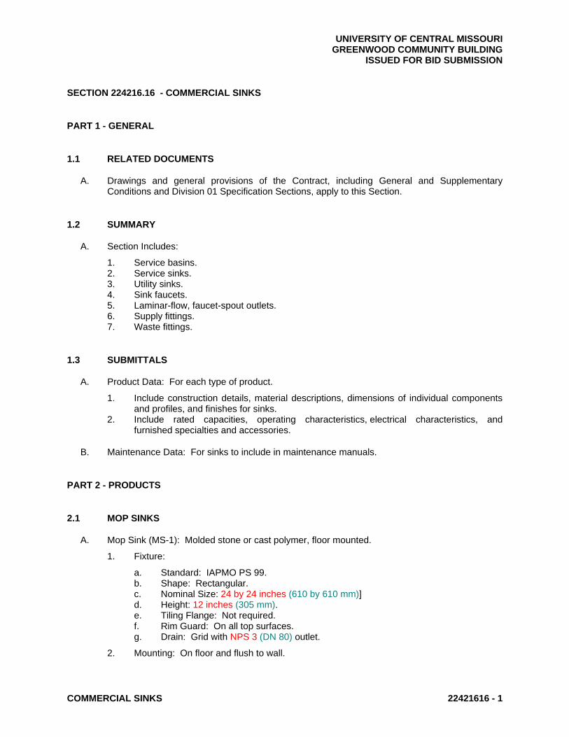
UNIVERSITY OF CENTRAL MISSOURI GREENWOOD COMMUNITY BUILDING ISSUED FOR BID SUBMISSION
COMMERCIAL SINKS 22421616 - 1
SECTION 224216.16 - COMMERCIAL SINKS
PART 1 - GENERAL
1.1 RELATED DOCUMENTS
A. Drawings and general provisions of the Contract, including General and Supplementary Conditions and Division 01 Specification Sections, apply to this Section.
1.2 SUMMARY
A. Section Includes:
1. Service basins. 2. Service sinks. 3. Utility sinks. 4. Sink faucets. 5. Laminar-flow, faucet-spout outlets. 6. Supply fittings. 7. Waste fittings.
1.3 SUBMITTALS
A. Product Data: For each type of product.
1. Include construction details, material descriptions, dimensions of individual components and profiles, and finishes for sinks.
2. Include rated capacities, operating characteristics, electrical characteristics, and furnished specialties and accessories.
B. Maintenance Data: For sinks to include in maintenance manuals.
PART 2 - PRODUCTS
2.1 MOP SINKS
A. Mop Sink (MS-1): Molded stone or cast polymer, floor mounted.
1. Fixture:
a. Standard: IAPMO PS 99. b. Shape: Rectangular. c. Nominal Size: 24 by 24 inches (610 by 610 mm)] d. Height: 12 inches (305 mm). e. Tiling Flange: Not required. f. Rim Guard: On all top surfaces. g. Drain: Grid with NPS 3 (DN 80) outlet.
2. Mounting: On floor and flush to wall.

UNIVERSITY OF CENTRAL MISSOURI GREENWOOD COMMUNITY BUILDING ISSUED FOR BID SUBMISSION
COMMERCIAL SINKS 22421616 - 2
3. Faucet: Wall mounted service sink type faucet with support bracket, pail hook, spout hose. Provide individual wall mounted mop support.
2.2 KITCHEN SINK
A. Sink (KS-1): Stainless steel, counter mounted with sealant.
1. Fixture: As scheduled on drawings
a. Standard: ASME A112.19.3/CSA B45.4. b. Type: counter mounted. c. Number of Compartments: One. d. Metal Thickness: 0.050 inch (1.3 mm). e. Compartment:
1) Drain: Grid with NPS 1-1/2 (DN 40) tailpiece and twist drain. 2) Drain Location: Centered in compartment.
2. Faucet: As scheduled on drawings. 3. Supply Fittings:
a. Standard: ASME A112.18.1/CSA B125.1. b. Supplies: Chrome-plated brass compression stop with inlet connection matching
water-supply piping type and size.
1) Operation: Wheel handle. 2) Risers: NPS 1/2 (DN 15), chrome-plated, soft-copper flexible tube or
ASME A112.18.6, braided or corrugated stainless-steel flexible hose.
4. Waste Fittings:
a. Standard: ASME A112.18.2/CSA B125.2. b. Trap(s):
1) Size: NPS 1-1/2 (DN 40). 2) Material: Chrome-plated, two-piece, cast-brass trap and swivel elbow with
0.032-inch- (0.83-mm-) thick brass tube to wall or two-piece, cast-brass trap and ground-joint swivel elbow with 0.032-inch- (0.83-mm-); and chrome-plated brass or steel wall flange.
3) Material: Stainless-steel, two-piece trap and swivel elbow with 0.012-inch- (0.30-mm-) thick stainless-steel tube to wall; and stainless-steel wall flange.
c. Continuous Waste:
1) Size: NPS 1-1/2 (DN 40). 2) Material: Chrome-plated, 0.032-inch- (0.83-mm-) thick brass tube.
2.3 LAUNDRY SINK
A. Sink (LS-1): Stainless steel, wall hung with sealant.
1. Fixture: As scheduled on drawings
a. Standard: ASME A112.19.3/CSA B45.4. b. Number of Compartments: One. c. Metal Thickness: 0.050 inch (1.3 mm). d. Compartment:
1) Drain: Grid with NPS 1-1/2 (DN 40) tailpiece and twist drain.

UNIVERSITY OF CENTRAL MISSOURI GREENWOOD COMMUNITY BUILDING ISSUED FOR BID SUBMISSION
COMMERCIAL SINKS 22421616 - 3
2) Drain Location: Centered in compartment.
2. Faucet: As scheduled on drawings. 3. Supply Fittings:
a. Standard: ASME A112.18.1/CSA B125.1. b. Supplies: Chrome-plated brass compression stop with inlet connection matching
water-supply piping type and size.
1) Operation: Wheel handle. 2) Risers: NPS 1/2 (DN 15), chrome-plated, soft-copper flexible tube or
ASME A112.18.6, braided or corrugated stainless-steel flexible hose.
4. Waste Fittings:
a. Standard: ASME A112.18.2/CSA B125.2. b. Trap(s):
1) Size: NPS 1-1/2 (DN 40). 2) Material: Chrome-plated, two-piece, cast-brass trap and swivel elbow with
0.032-inch- (0.83-mm-) thick brass tube to wall or two-piece, cast-brass trap and ground-joint swivel elbow with 0.032-inch- (0.83-mm-); and chrome-plated brass or steel wall flange.
3) Material: Stainless-steel, two-piece trap and swivel elbow with 0.012-inch- (0.30-mm-) thick stainless-steel tube to wall; and stainless-steel wall flange.
c. Continuous Waste:
1) Size: NPS 1-1/2 (DN 40). 2) Material: Chrome-plated, 0.032-inch- (0.83-mm-) thick brass tube.
2.4 GROUT
A. Standard: ASTM C 1107/C 1107M, Grade B, post-hardening and volume-adjusting, dry, hydraulic-cement grout.
B. Characteristics: Nonshrink; recommended for interior and exterior applications.
C. Design Mix: 5000-psi (34.5-MPa), 28-day compressive strength.
D. Packaging: Premixed and factory packaged.
PART 3 - EXECUTION
3.1 EXAMINATION
A. Examine roughing-in of water supply and sanitary drainage and vent piping systems to verify actual locations of piping connections before sink installation.
B. Examine walls, floors, and counters for suitable conditions where sinks will be installed.
C. Proceed with installation only after unsatisfactory conditions have been corrected.

UNIVERSITY OF CENTRAL MISSOURI GREENWOOD COMMUNITY BUILDING ISSUED FOR BID SUBMISSION
COMMERCIAL SINKS 22421616 - 4
3.2 INSTALLATION
A. Install sinks level and plumb according to roughing-in drawings.
B. Set floor-mounted sinks in leveling bed of cement grout.
C. Install water-supply piping with stop on each supply to each sink faucet.
1. Exception: Use ball or globe valves if supply stops are not specified with sink. Comply with valve requirements specified in Section 220523 "General-Duty Valves for Plumbing Piping."
2. Install stops in locations where they can be easily reached for operation.
D. Install wall flanges or escutcheons at piping wall penetrations in exposed, finished locations. Use deep-pattern escutcheons if required to conceal protruding fittings. Comply with escutcheon requirements specified in Section 220518 "Escutcheons for Plumbing Piping."
E. Seal joints between sinks and counters, floors, and walls using sanitary-type, one-part, mildew-resistant silicone sealant. Match sealant color to fixture color. Comply with sealant requirements specified in Section 079200 "Joint Sealants."
F. Install protective shielding pipe covers and enclosures on exposed supplies and waste piping of accessible sinks. Comply with requirements in Section 220719 "Plumbing Piping Insulation."
3.3 CONNECTIONS
A. Connect sinks with water supplies, stops, and risers, and with traps, soil, waste, and vent piping. Use size fittings required to match fixtures.
B. Comply with water piping requirements specified in Section 221116 "Domestic Water Piping."
C. Comply with soil and waste piping requirements specified in Section 221316 "Sanitary Waste and Vent Piping."
3.4 ADJUSTING
A. Operate and adjust sinks and controls. Replace damaged and malfunctioning sinks, fittings, and controls.
B. Adjust water pressure at faucets to produce proper flow.
3.5 CLEANING AND PROTECTION
A. After completing installation of sinks, inspect and repair damaged finishes.
B. Clean sinks, faucets, and other fittings with manufacturers' recommended cleaning methods and materials.
C. Provide protective covering for installed sinks and fittings.
D. Do not allow use of sinks for temporary facilities unless approved in writing by Owner.

UNIVERSITY OF CENTRAL MISSOURI GREENWOOD COMMUNITY BUILDING ISSUED FOR BID SUBMISSION
COMMERCIAL SINKS 22421616 - 5
END OF SECTION 224216.16

UNIVERSITY OF CENTRAL MISSOURI GREENWOOD COMMUNITY BUILDING ISSUED FOR BID SUBMISSION
PRESSURE WATER COOLERS 224716 - 1
SECTION 224716 - PRESSURE WATER COOLERS
PART 1 - GENERAL
1.1 SUMMARY
A. Section includes pressure water coolers and related components.
1.2 SUBMITTALS
A. Product Data: For each type of pressure water cooler.
B. Shop Drawings: Include diagrams for power, signal, and control wiring.
C. Maintenance Data: For pressure water coolers to include in maintenance manuals.
PART 2 - PRODUCTS
2.1 PRESSURE WATER COOLERS
A. Pressure Water Coolers (EWC-1): Wall mounted as scheduled on the drawings.
1. Cabinet: Bi-level with two attached contoured bowls, all stainless steel. 2. Bubbler: One, with adjustable stream regulator, located on each cabinet deck. 3. Control: Push button on front end. 4. Drain: Grid with NPS 1-1/4 (DN 32) tailpiece. 5. Supply: NPS 3/8 (DN 10) with shutoff valve. 6. Waste Fitting: ASME A112.18.2/CSA B125.2, NPS 1-1/4 (DN 32) brass P-trap. 7. Filter: One or more water filters complying with NSF 42 and NSF 53 for cyst and lead
reduction to below EPA standards; with capacity sized for unit peak flow rate. 8. Cooling System: Electric, with hermetically sealed compressor, cooling coil, air-cooled
condensing unit, corrosion-resistant tubing, refrigerant, corrosion-resistant-metal storage tank, and adjustable thermostat.
a. Electrical Components, Devices, and Accessories: Listed and labeled as defined in NFPA 70, by a qualified testing agency, and marked for intended location and application.
9. Capacities and Characteristics:
a. Cooled Water: 8 gph (0.0084 L/s) b. Ambient-Air Temperature: 90 deg F (32 deg C). c. Inlet-Water Temperature: 80 deg F (27 deg C). d. Cooled-Water Temperature: 50 deg F (10 deg C). e. Electrical Characteristics:
1) Motor Horsepower: 370 watts. 2) Volts: 120-V ac. 3) Phase: Single. 4) Hertz: 60. 5) Full-Load Amperes: 4.0.

UNIVERSITY OF CENTRAL MISSOURI GREENWOOD COMMUNITY BUILDING ISSUED FOR BID SUBMISSION
PRESSURE WATER COOLERS 224716 - 2
10. Support: ASME A112.6.1M, Type I water-cooler carrier.
PART 3 - EXECUTION
3.1 EXAMINATION
A. Examine roughing-in for water-supply and sanitary drainage and vent piping systems to verify actual locations of piping connections before fixture installation.
B. Examine walls and floors for suitable conditions where fixtures will be installed.
C. Proceed with installation only after unsatisfactory conditions have been corrected.
3.2 INSTALLATION
A. Install fixtures level and plumb according to roughing-in drawings. For fixtures indicated for children, install at height required by authorities having jurisdiction.
B. Install off-the-floor carrier supports, affixed to building substrate, for wall-mounted fixtures.
C. Install water-supply piping with shutoff valve on supply to each fixture to be connected to domestic-water distribution piping. Use ball or globe valve. Install valves in locations where they can be easily reached for operation. Valves are specified in Section 220523 "General-Duty Valves for Plumbing Piping."
D. Install trap and waste piping on drain outlet of each fixture to be connected to sanitary drainage system.
E. Install wall flanges or escutcheons at piping wall penetrations in exposed, finished locations. Use deep-pattern escutcheons where required to conceal protruding fittings. Comply with escutcheon requirements specified in Section 220518 "Escutcheons for Plumbing Piping."
F. Seal joints between fixtures and walls using sanitary-type, one-part, mildew-resistant, silicone sealant. Match sealant color to fixture color. Comply with sealant requirements specified in Section 079200 "Joint Sealants."
3.3 CONNECTIONS
A. Connect fixtures with water supplies, stops, and risers, and with traps, soil, waste, and vent piping. Use size fittings required to match fixtures.
B. Comply with water piping requirements specified in Section 221116 "Domestic Water Piping."
C. Install ball or globe shutoff valve on water supply to each fixture. Comply with valve requirements specified in Section 220523 "General-Duty Valves for Plumbing Piping."
D. Comply with soil and waste piping requirements specified in Section 221316 "Sanitary Waste and Vent Piping."

UNIVERSITY OF CENTRAL MISSOURI GREENWOOD COMMUNITY BUILDING ISSUED FOR BID SUBMISSION
PRESSURE WATER COOLERS 224716 - 3
3.4 ADJUSTING
A. Adjust fixture flow regulators for proper flow and stream height.
B. Adjust pressure water-cooler temperature settings.
3.5 CLEANING
A. After installing fixture, inspect unit. Remove paint splatters and other spots, dirt, and debris. Repair damaged finish to match original finish.
B. Clean fixtures, on completion of installation, according to manufacturer's written instructions.
C. Provide protective covering for installed fixtures.
D. Do not allow use of fixtures for temporary facilities unless approved in writing by Owner.
END OF SECTION 224716

UNIVERSITY OF CENTRAL MISSOURI GREENWOOD COMMUNITY BUILDING ISSUED FOR BID SUBMISSION
TESTING, ADJUSTING, AND BALANCING FOR HVAC 230593 - 1
SECTION 230593 - TESTING, ADJUSTING, AND BALANCING FOR HVAC
PART 1 - GENERAL
1.1 SUMMARY
A. Section Includes:
1. Balancing Air Systems:
a. Constant-volume air systems.
1.2 DEFINITIONS
A. AABC: Associated Air Balance Council.
B. NEBB: National Environmental Balancing Bureau.
C. TAB: Testing, adjusting, and balancing.
D. TABB: Testing, Adjusting, and Balancing Bureau.
E. TAB Specialist: An entity engaged to perform TAB Work.
1.3 SUBMITTALS
A. Certified TAB reports.
1.4 QUALITY ASSURANCE
A. TAB Contractor Qualifications: Engage a TAB entity certified by AABC, NEBB or TABB.
1. TAB Field Supervisor: Employee of the TAB contractor and certified by AABC, NEBB or TABB
2. TAB Technician: Employee of the TAB contractor and who is certified by AABC, NEBB or TABB as a TAB technician.
B. Certify TAB field data reports and perform the following:
1. Review field data reports to validate accuracy of data and to prepare certified TAB reports.
2. Certify that the TAB team complied with the approved TAB plan and the procedures specified and referenced in this Specification.
C. TAB Report Forms: Use standard TAB contractor's forms
D. Instrumentation Type, Quantity, Accuracy, and Calibration: As described in ASHRAE 111, Section 5, "Instrumentation."

UNIVERSITY OF CENTRAL MISSOURI GREENWOOD COMMUNITY BUILDING ISSUED FOR BID SUBMISSION
TESTING, ADJUSTING, AND BALANCING FOR HVAC 230593 - 2
E. ASHRAE Compliance: Applicable requirements in ASHRAE 62.1, Section 7.2.2 - "Air Balancing."
F. ASHRAE/IESNA Compliance: Applicable requirements in ASHRAE/IESNA 90.1, Section 6.7.2.3 - "System Balancing."
PART 2 - PRODUCTS (Not Applicable)
PART 3 - EXECUTION
3.1 EXAMINATION
A. Examine the Contract Documents to become familiar with Project requirements and to discover conditions in systems' designs that may preclude proper TAB of systems and equipment.
B. Examine systems for installed balancing devices, such as test ports, gage cocks, thermometer wells, flow-control devices, balancing valves and fittings, and manual volume dampers. Verify that locations of these balancing devices are accessible.
C. Examine the approved submittals for HVAC systems and equipment.
D. Examine design data including HVAC system descriptions, statements of design assumptions for environmental conditions and systems' output, and statements of philosophies and assumptions about HVAC system and equipment controls.
E. Examine equipment performance data including fan curves.
1. Relate performance data to Project conditions and requirements, including system effects that can create undesired or unpredicted conditions that cause reduced capacities in all or part of a system.
2. Calculate system-effect factors to reduce performance ratings of HVAC equipment when installed under conditions different from the conditions used to rate equipment performance. To calculate system effects for air systems, use tables and charts found in AMCA 201, "Fans and Systems," or in SMACNA's "HVAC Systems - Duct Design." Compare results with the design data and installed conditions.
F. Examine system and equipment installations and verify that field quality-control testing, cleaning, and adjusting specified in individual Sections have been performed.
G. Examine test reports specified in individual system and equipment Sections.
H. Examine HVAC equipment and filters and verify that bearings are greased, belts are aligned and tight, and equipment with functioning controls is ready for operation.
I. Examine heat-transfer coils for correct piping connections and for clean and straight fins.
J. Examine operating safety interlocks and controls on HVAC equipment.
K. Report deficiencies discovered before and during performance of TAB procedures. Observe and record system reactions to changes in conditions. Record default set points if different from indicated values.
UNIVERSITY OF CENTRAL MISSOURI GREENWOOD COMMUNITY BUILDING ISSUED FOR BID SUBMISSION
TESTING, ADJUSTING, AND BALANCING FOR HVAC 230593 - 3
3.2 GENERAL PROCEDURES FOR TESTING AND BALANCING
A. Perform testing and balancing procedures on each system according to the procedures contained in AABC's "National Standards for Total System Balance", NEBB's "Procedural Standards for Testing, Adjusting, and Balancing of Environmental Systems" or SMACNA's "HVAC Systems - Testing, Adjusting, and Balancing" and in this Section.
B. Cut insulation, ducts, pipes, and equipment cabinets for installation of test probes to the minimum extent necessary for TAB procedures.
1. After testing and balancing, patch probe holes in ducts with same material and thickness as used to construct ducts.
2. Install and join new insulation that matches removed materials. Restore insulation, coverings, vapor barrier, and finish according to Section 230713 "Duct Insulation," Section 230716 "HVAC Equipment Insulation," Section 230719 "HVAC Piping Insulation."
C. Mark equipment and balancing devices, including damper-control positions, valve position indicators, fan-speed-control levers, and similar controls and devices, with paint or other suitable, permanent identification material to show final settings.
D. Take and report testing and balancing measurements in inch-pound (IP) units.
3.3 GENERAL PROCEDURES FOR BALANCING AIR SYSTEMS
A. Prepare test reports for both fans and outlets. Obtain manufacturer's outlet factors and recommended testing procedures. Crosscheck the summation of required outlet volumes with required fan volumes.
B. Prepare schematic diagrams of systems' "as-built" duct layouts.
C. Determine the best locations in main and branch ducts for accurate duct-airflow measurements.
D. Check airflow patterns from the outdoor-air louvers and dampers and the return- and exhaust-air dampers through the supply-fan discharge and mixing dampers.
E. Locate start-stop and disconnect switches, electrical interlocks, and motor starters.
F. Verify that motor starters are equipped with properly sized thermal protection.
G. Check dampers for proper position to achieve desired airflow path.
H. Check for airflow blockages.
I. Check condensate drains for proper connections and functioning.
J. Check for proper sealing of air-handling-unit components.
K. Verify that air duct system is sealed as specified in Section 233113 "Metal Ducts."
3.4 PROCEDURES FOR CONSTANT-VOLUME AIR SYSTEMS
A. Adjust fans to deliver total indicated airflows within the maximum allowable fan speed listed by fan manufacturer.

UNIVERSITY OF CENTRAL MISSOURI GREENWOOD COMMUNITY BUILDING ISSUED FOR BID SUBMISSION
TESTING, ADJUSTING, AND BALANCING FOR HVAC 230593 - 4
1. Measure total airflow.
a. Where sufficient space in ducts is unavailable for Pitot-tube traverse measurements, measure airflow at terminal outlets and inlets and calculate the total airflow.
2. Measure fan static pressures as follows to determine actual static pressure:
a. Measure outlet static pressure as far downstream from the fan as practical and upstream from restrictions in ducts such as elbows and transitions.
b. Measure static pressure directly at the fan outlet or through the flexible connection. c. Measure inlet static pressure of single-inlet fans in the inlet duct as near the fan as
possible, upstream from the flexible connection, and downstream from duct restrictions.
d. Measure inlet static pressure of double-inlet fans through the wall of the plenum that houses the fan.
3. Measure static pressure across each component that makes up an air-handling unit, rooftop unit, and other air-handling and -treating equipment.
a. Report the cleanliness status of filters and the time static pressures are measured.
4. Measure static pressures entering and leaving other devices, such as sound traps, heat-recovery equipment, and air washers, under final balanced conditions.
5. Review Record Documents to determine variations in design static pressures versus actual static pressures. Calculate actual system-effect factors. Recommend adjustments to accommodate actual conditions.
6. Obtain approval from Design Professional for adjustment of fan speed higher or lower than indicated speed. Comply with requirements in Sections for air-handling units for adjustment of fans, belts, and pulley sizes to achieve indicated air-handling-unit performance.
7. Do not make fan-speed adjustments that result in motor overload. Consult equipment manufacturers about fan-speed safety factors. Modulate dampers and measure fan-motor amperage to ensure that no overload will occur. Measure amperage in full-cooling, full-heating, economizer, and any other operating mode to determine the maximum required brake horsepower.
B. Adjust volume dampers for main duct, submain ducts, and major branch ducts to indicated airflows within specified tolerances.
1. Measure airflow of submain and branch ducts.
a. Where sufficient space in submain and branch ducts is unavailable for Pitot-tube traverse measurements, measure airflow at terminal outlets and inlets and calculate the total airflow for that zone.
2. Measure static pressure at a point downstream from the balancing damper, and adjust volume dampers until the proper static pressure is achieved.
3. Remeasure each submain and branch duct after all have been adjusted. Continue to adjust submain and branch ducts to indicated airflows within specified tolerances.
3.5 PROCEDURES FOR MOTORS
A. Motors, 1/2 HP and Larger: Test at final balanced conditions and record the following data:
1. Manufacturer's name, model number, and serial number. 2. Motor horsepower rating. 3. Motor rpm. 4. Efficiency rating.

UNIVERSITY OF CENTRAL MISSOURI GREENWOOD COMMUNITY BUILDING ISSUED FOR BID SUBMISSION
TESTING, ADJUSTING, AND BALANCING FOR HVAC 230593 - 5
5. Nameplate and measured voltage, each phase. 6. Nameplate and measured amperage, each phase. 7. Starter thermal-protection-element rating.
3.6 PROCEDURES FOR CONDENSING UNITS
A. Verify proper rotation of fans.
B. Measure entering- and leaving-air temperatures.
C. Record compressor data.
3.7 PROCEDURES FOR HEAT-TRANSFER COILS
A. Measure, adjust, and record the following data for each refrigerant coil:
1. Dry-bulb temperature of entering and leaving air. 2. Wet-bulb temperature of entering and leaving air. 3. Airflow. 4. Air pressure drop. 5. Refrigerant suction pressure and temperature.
3.8 TOLERANCES
A. Set HVAC system's air flow rates and water flow rates within the following tolerances:
1. Supply and Exhaust Fans: Plus or minus 10 percent.
3.9 REPORTING
A. Initial Construction-Phase Report: Based on examination of the Contract Documents as specified in "Examination" Article, prepare a report on the adequacy of design for systems' balancing devices. Recommend changes and additions to systems' balancing devices to facilitate proper performance measuring and balancing. Recommend changes and additions to HVAC systems and general construction to allow access for performance measuring and balancing devices.
3.10 FINAL REPORT
A. General: Prepare a certified written report; tabulate and divide the report into separate sections for tested systems and balanced systems.
1. Include a certification sheet at the front of the report's binder, signed and sealed by the certified testing and balancing Design Professional.
2. Include a list of instruments used for procedures, along with proof of calibration.
B. Final Report Contents: In addition to certified field-report data, include the following
1. Fan curves. 2. Manufacturers' test data. 3. Field test reports prepared by system and equipment installers.

UNIVERSITY OF CENTRAL MISSOURI GREENWOOD COMMUNITY BUILDING ISSUED FOR BID SUBMISSION
TESTING, ADJUSTING, AND BALANCING FOR HVAC 230593 - 6
4. Other information relative to equipment performance; do not include Shop Drawings and product data.
C. General Report Data: In addition to form titles and entries, include the following data:
1. Title page. 2. Name and address of the TAB contractor. 3. Project name. 4. Project location. 5. Design Professional's name and address. 6. Contractor's name and address. 7. Report date. 8. Signature of TAB supervisor who certifies the report. 9. Table of Contents with the total number of pages defined for each section of the report.
Number each page in the report. 10. Summary of contents including the following:
a. Indicated versus final performance. b. Notable characteristics of systems. c. Description of system operation sequence if it varies from the Contract
Documents.
11. Nomenclature sheets for each item of equipment. 12. Data for terminal units, including manufacturer's name, type, size, and fittings. 13. Notes to explain why certain final data in the body of reports vary from indicated values. 14. Test conditions for fans performance forms including the following:
a. Conditions of filters. b. Cooling coil, wet- and dry-bulb conditions. c. Other system operating conditions that affect performance.
D. System Diagrams: Include schematic layouts of air distribution systems. Present each system with single-line diagram and include the following:
1. Quantities of outdoor, supply, return, and exhaust airflows. 2. Duct, outlet, and inlet sizes. 3. Position of balancing devices.
3.11 ADDITIONAL TESTS
A. Within 90 days of completing TAB, perform additional TAB to verify that balanced conditions are being maintained throughout and to correct unusual conditions.
B. Seasonal Periods: If initial TAB procedures were not performed during near-peak summer and winter conditions, perform additional TAB during near-peak summer and winter conditions.
END OF SECTION 230593
UNIVERSITY OF CENTRAL MISSOURI GREENWOOD COMMUNITY BUILDING ISSUED FOR BID SUBMISSION
DUCT INSULATION 230713 - 1
SECTION 230713 - DUCT INSULATION
PART 1 - GENERAL
1.1 SUMMARY
A. Section includes insulating the following duct services:
1. Indoor, supply, return and outdoor air.
1.2 SUBMITTALS
A. Product Data: For each type of product indicated.
B. Field quality-control reports.
1.3 QUALITY ASSURANCE
A. Surface-Burning Characteristics: For insulation and related materials, as determined by testing identical products according to ASTM E 84, by a testing agency acceptable to authorities having jurisdiction. Factory label insulation and jacket materials and adhesive, mastic, tapes, and cement material containers, with appropriate markings of applicable testing agency.
1. Insulation Installed Indoors: Flame-spread index of 25 or less, and smoke-developed index of 50 or less.
PART 2 - PRODUCTS
2.1 INSULATION MATERIALS
A. Comply with requirements in "Duct Insulation Schedules.”
B. Products shall not contain asbestos, lead, mercury, or mercury compounds.
C. Products that come in contact with stainless steel shall have a leachable chloride content of less than 50 ppm when tested according to ASTM C 871.
D. Insulation materials for use on austenitic stainless steel shall be qualified as acceptable according to ASTM C 795.
E. Foam insulation materials shall not use CFC or HCFC blowing agents in the manufacturing process.
F. Mineral-Fiber Blanket Insulation: Mineral or glass fibers bonded with a thermosetting resin. Comply with ASTM C 553, Type II and ASTM C 1290, Type II with factory-applied vinyl jacket or Type III with factory-applied FSK jacket . Factory-applied jacket requirements are specified in "Factory-Applied Jackets" Article.

UNIVERSITY OF CENTRAL MISSOURI GREENWOOD COMMUNITY BUILDING ISSUED FOR BID SUBMISSION
DUCT INSULATION 230713 - 2
2.2 ADHESIVES
A. Materials shall be compatible with insulation materials, jackets, and substrates and for bonding insulation to itself and to surfaces to be insulated unless otherwise indicated.
B. Mineral-Fiber Adhesive: Comply with MIL-A-3316C, Class 2, Grade A.
1. For indoor applications, adhesive shall have a VOC content of 80 g/L or less when calculated according to 40 CFR 59, Subpart D (EPA Method 24).
2. Adhesive shall comply with the testing and product requirements of the California Department of Health Services' "Standard Practice for the Testing of Volatile Organic Emissions from Various Sources Using Small-Scale Environmental Chambers."
C. ASJ Adhesive, and FSK Jacket Adhesive: Comply with MIL-A-3316C, Class 2, Grade A for bonding insulation jacket lap seams and joints.
1. For indoor applications, adhesive shall have a VOC content of 50 g/L or less when calculated according to 40 CFR 59, Subpart D (EPA Method 24).
2. Adhesive shall comply with the testing and product requirements of the California Department of Health Services' "Standard Practice for the Testing of Volatile Organic Emissions from Various Sources Using Small-Scale Environmental Chambers."
2.3 MASTICS
A. Materials shall be compatible with insulation materials, jackets, and substrates; comply with MIL-PRF-19565C, Type II.
1. For indoor applications, use mastics that have a VOC content of 50 g/L or less when calculated according to 40 CFR 59, Subpart D (EPA Method 24).
B. Vapor-Barrier Mastic: Water based; suitable for indoor use on below ambient services.
1. Water-Vapor Permeance: ASTM E 96/E 96M, Procedure B, 0.013 perm at 43-mil dry film thickness.
2. Service Temperature Range: Minus 20 to plus 180 deg F. 3. Solids Content: ASTM D 1644, 58 percent by volume and 70 percent by weight. 4. Color: White.
C. Breather Mastic: Water based; suitable for indoor and outdoor use on above ambient services.
1. Water-Vapor Permeance: ASTM F 1249, 1.8 perms at 0.0625-inch dry film thickness. 2. Service Temperature Range: Minus 20 to plus 180 deg F. 3. Solids Content: 60 percent by volume and 66 percent by weight. 4. Color: White.
2.4 SEALANTS
A. FSK Jacket Flashing Sealants:
1. Materials shall be compatible with insulation materials, jackets, and substrates. 2. Fire- and water-resistant, flexible, elastomeric sealant. 3. Service Temperature Range: Minus 40 to plus 250 deg F. 4. Color: Aluminum. 5. For indoor applications, use sealants that have a VOC content of 420 g/L or less when
calculated according to 40 CFR 59, Subpart D (EPA Method 24).

UNIVERSITY OF CENTRAL MISSOURI GREENWOOD COMMUNITY BUILDING ISSUED FOR BID SUBMISSION
DUCT INSULATION 230713 - 3
6. Sealants shall comply with the testing and product requirements of the California Department of Health Services' "Standard Practice for the Testing of Volatile Organic Emissions from Various Sources Using Small-Scale Environmental Chambers."
B. ASJ Flashing Sealants, and Vinyl Jacket Flashing Sealants:
1. Materials shall be compatible with insulation materials, jackets, and substrates. 2. Fire- and water-resistant, flexible, elastomeric sealant. 3. Service Temperature Range: Minus 40 to plus 250 deg F. 4. Color: White. 5. For indoor applications, sealants shall have a VOC content of 420 g/L or less when
calculated according to 40 CFR 59, Subpart D (EPA Method 24). 6. Sealants shall comply with the testing and product requirements of the California
Department of Health Services' "Standard Practice for the Testing of Volatile Organic Emissions from Various Sources Using Small-Scale Environmental Chambers."
2.5 FACTORY-APPLIED JACKETS
A. Insulation system schedules indicate factory-applied jackets on various applications. When factory-applied jackets are indicated, comply with the following:
1. ASJ: White, kraft-paper, fiberglass-reinforced scrim with aluminum-foil backing; complying with ASTM C 1136, Type I.
2. FSK Jacket: Aluminum-foil, fiberglass-reinforced scrim with kraft-paper backing; complying with ASTM C 1136, Type II.
3. Vinyl Jacket: White vinyl with a permeance of 1.3 perms when tested according to ASTM E 96/E 96M, Procedure A, and complying with NFPA 90A and NFPA 90B.
2.6 TAPES
A. ASJ Tape: White vapor-retarder tape matching factory-applied jacket with acrylic adhesive, complying with ASTM C 1136.
1. Width: 3 inches. 2. Thickness: 11.5 mils. 3. Adhesion: 90 ounces force/inch in width. 4. Elongation: 2 percent. 5. Tensile Strength: 40 lbf/inch in width. 6. ASJ Tape Disks and Squares: Precut disks or squares of ASJ tape.
B. FSK Tape: Foil-face, vapor-retarder tape matching factory-applied jacket with acrylic adhesive; complying with ASTM C 1136.
1. Width: 3 inches. 2. Thickness: 6.5 mils. 3. Adhesion: 90 ounces force/inch in width. 4. Elongation: 2 percent. 5. Tensile Strength: 40 lbf/inch in width. 6. FSK Tape Disks and Squares: Precut disks or squares of FSK tape.
2.7 SECUREMENTS
A. Insulation Pins and Hangers:
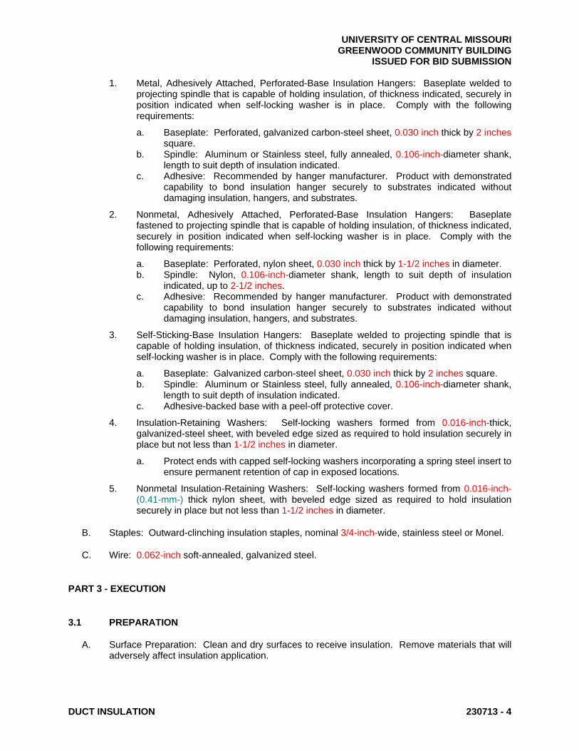
UNIVERSITY OF CENTRAL MISSOURI GREENWOOD COMMUNITY BUILDING ISSUED FOR BID SUBMISSION
DUCT INSULATION 230713 - 4
1. Metal, Adhesively Attached, Perforated-Base Insulation Hangers: Baseplate welded to projecting spindle that is capable of holding insulation, of thickness indicated, securely in position indicated when self-locking washer is in place. Comply with the following requirements:
a. Baseplate: Perforated, galvanized carbon-steel sheet, 0.030 inch thick by 2 inches square.
b. Spindle: Aluminum or Stainless steel, fully annealed, 0.106-inch-diameter shank, length to suit depth of insulation indicated.
c. Adhesive: Recommended by hanger manufacturer. Product with demonstrated capability to bond insulation hanger securely to substrates indicated without damaging insulation, hangers, and substrates.
2. Nonmetal, Adhesively Attached, Perforated-Base Insulation Hangers: Baseplate fastened to projecting spindle that is capable of holding insulation, of thickness indicated, securely in position indicated when self-locking washer is in place. Comply with the following requirements:
a. Baseplate: Perforated, nylon sheet, 0.030 inch thick by 1-1/2 inches in diameter. b. Spindle: Nylon, 0.106-inch-diameter shank, length to suit depth of insulation
indicated, up to 2-1/2 inches. c. Adhesive: Recommended by hanger manufacturer. Product with demonstrated
capability to bond insulation hanger securely to substrates indicated without damaging insulation, hangers, and substrates.
3. Self-Sticking-Base Insulation Hangers: Baseplate welded to projecting spindle that is capable of holding insulation, of thickness indicated, securely in position indicated when self-locking washer is in place. Comply with the following requirements:
a. Baseplate: Galvanized carbon-steel sheet, 0.030 inch thick by 2 inches square. b. Spindle: Aluminum or Stainless steel, fully annealed, 0.106-inch-diameter shank,
length to suit depth of insulation indicated. c. Adhesive-backed base with a peel-off protective cover.
4. Insulation-Retaining Washers: Self-locking washers formed from 0.016-inch-thick, galvanized-steel sheet, with beveled edge sized as required to hold insulation securely in place but not less than 1-1/2 inches in diameter.
a. Protect ends with capped self-locking washers incorporating a spring steel insert to ensure permanent retention of cap in exposed locations.
5. Nonmetal Insulation-Retaining Washers: Self-locking washers formed from 0.016-inch- (0.41-mm-) thick nylon sheet, with beveled edge sized as required to hold insulation securely in place but not less than 1-1/2 inches in diameter.
B. Staples: Outward-clinching insulation staples, nominal 3/4-inch-wide, stainless steel or Monel.
C. Wire: 0.062-inch soft-annealed, galvanized steel.
PART 3 - EXECUTION
3.1 PREPARATION
A. Surface Preparation: Clean and dry surfaces to receive insulation. Remove materials that will adversely affect insulation application.

UNIVERSITY OF CENTRAL MISSOURI GREENWOOD COMMUNITY BUILDING ISSUED FOR BID SUBMISSION
DUCT INSULATION 230713 - 5
3.2 GENERAL INSTALLATION REQUIREMENTS
A. Install insulation materials, accessories, and finishes with smooth, straight, and even surfaces; free of voids throughout the length of ducts and fittings.
B. Install insulation materials, vapor barriers or retarders, jackets, and thicknesses required for each item of duct system as specified in insulation system schedules.
C. Install accessories compatible with insulation materials and suitable for the service. Install accessories that do not corrode, soften, or otherwise attack insulation or jacket in either wet or dry state.
D. Install insulation with longitudinal seams at top and bottom of horizontal runs.
E. Install multiple layers of insulation with longitudinal and end seams staggered.
F. Keep insulation materials dry during application and finishing.
G. Install insulation with tight longitudinal seams and end joints. Bond seams and joints with adhesive recommended by insulation material manufacturer.
H. Install insulation with least number of joints practical.
I. Where vapor barrier is indicated, seal joints, seams, and penetrations in insulation at hangers, supports, anchors, and other projections with vapor-barrier mastic.
1. Install insulation continuously through hangers and around anchor attachments. 2. For insulation application where vapor barriers are indicated, extend insulation on anchor
legs from point of attachment to supported item to point of attachment to structure. Taper and seal ends at attachment to structure with vapor-barrier mastic.
3. Install insert materials and install insulation to tightly join the insert. Seal insulation to insulation inserts with adhesive or sealing compound recommended by insulation material manufacturer.
J. Apply adhesives, mastics, and sealants at manufacturer's recommended coverage rate and wet and dry film thicknesses.
K. Install insulation with factory-applied jackets as follows:
1. Draw jacket tight and smooth. 2. Cover circumferential joints with 3-inch-wide strips, of same material as insulation jacket.
Secure strips with adhesive and outward clinching staples along both edges of strip, spaced 4 inches o.c.
3. Overlap jacket longitudinal seams at least 1-1/2 inches. Clean and dry surface to receive self-sealing lap. Staple laps with outward clinching staples along edge at 2 inches o.c.
a. For below ambient services, apply vapor-barrier mastic over staples.
4. Cover joints and seams with tape, according to insulation material manufacturer's written instructions, to maintain vapor seal.
5. Where vapor barriers are indicated, apply vapor-barrier mastic on seams and joints and at ends adjacent to duct flanges and fittings.
L. Cut insulation in a manner to avoid compressing insulation more than 75 percent of its nominal thickness.

UNIVERSITY OF CENTRAL MISSOURI GREENWOOD COMMUNITY BUILDING ISSUED FOR BID SUBMISSION
DUCT INSULATION 230713 - 6
M. Finish installation with systems at operating conditions. Repair joint separations and cracking due to thermal movement.
N. Repair damaged insulation facings by applying same facing material over damaged areas. Extend patches at least 4 inches beyond damaged areas. Adhere, staple, and seal patches similar to butt joints.
3.3 PENETRATIONS
A. Insulation Installation at Interior Wall and Partition Penetrations (That Are Not Fire Rated): Install insulation continuously through walls and partitions.
B. Insulation Installation at Fire-Rated Wall and Partition Penetrations: Terminate insulation at fire damper sleeves for fire-rated wall and partition penetrations. Externally insulate damper sleeves to match adjacent insulation and overlap duct insulation at least 2 inches.
1. Comply with requirements in Section 078413 "Penetration Firestopping" for firestopping and fire-resistive joint sealers.
3.4 INSTALLATION OF MINERAL-FIBER INSULATION
A. Blanket Insulation Installation on Ducts and Plenums: Secure with adhesive and insulation pins.
1. Apply adhesives according to manufacturer's recommended coverage rates per unit area, for 100 percent coverage of duct and plenum surfaces.
2. Apply adhesive to entire circumference of ducts and to all surfaces of fittings and transitions.
3. Install either capacitor-discharge-weld pins and speed washers or cupped-head, capacitor-discharge-weld pins on sides and bottom of horizontal ducts and sides of vertical ducts as follows:
a. On duct sides with dimensions 18 inches and smaller, place pins along longitudinal centerline of duct. Space 3 inches maximum from insulation end joints, and 16 inches o.c.
b. On duct sides with dimensions larger than 18 inches, place pins 16 inches o.c. each way, and 3 inches maximum from insulation joints. Install additional pins to hold insulation tightly against surface at cross bracing.
c. Pins may be omitted from top surface of horizontal, rectangular ducts and plenums.
d. Do not overcompress insulation during installation. e. Impale insulation over pins and attach speed washers. f. Cut excess portion of pins extending beyond speed washers or bend parallel with
insulation surface. Cover exposed pins and washers with tape matching insulation facing.
4. For ducts and plenums with surface temperatures below ambient, install a continuous unbroken vapor barrier. Create a facing lap for longitudinal seams and end joints with insulation by removing 2 inches from one edge and one end of insulation segment. Secure laps to adjacent insulation section with 1/2-inch outward-clinching staples, 1 inch o.c. Install vapor barrier consisting of factory- or field-applied jacket, adhesive, vapor-barrier mastic, and sealant at joints, seams, and protrusions.
a. Repair punctures, tears, and penetrations with tape or mastic to maintain vapor-barrier seal.

UNIVERSITY OF CENTRAL MISSOURI GREENWOOD COMMUNITY BUILDING ISSUED FOR BID SUBMISSION
DUCT INSULATION 230713 - 7
b. Install vapor stops for ductwork and plenums operating below 50 deg F at 18-foot (5.5-m) intervals. Vapor stops shall consist of vapor-barrier mastic applied in a Z-shaped pattern over insulation face, along butt end of insulation, and over the surface. Cover insulation face and surface to be insulated a width equal to two times the insulation thickness, but not less than 3 inches.
5. Overlap unfaced blankets a minimum of 2 inches on longitudinal seams and end joints. At end joints, secure with steel bands spaced a maximum of 18 inches o.c.
6. Install insulation on rectangular duct elbows and transitions with a full insulation section for each surface. Install insulation on round and flat-oval duct elbows with individually mitered gores cut to fit the elbow.
7. Insulate duct stiffeners, hangers, and flanges that protrude beyond insulation surface with 6-inch-wide strips of same material used to insulate duct. Secure on alternating sides of stiffener, hanger, and flange with pins spaced 6 inches o.c.
3.5 FINISHES
A. Insulation with ASJ or Other Paintable Jacket Material: Paint jacket with paint system identified below and as specified in Section 099123 "Interior Painting."
1. Flat Acrylic Finish: Two finish coats over a primer that is compatible with jacket material and finish coat paint. Add fungicidal agent to render fabric mildew proof.
a. Finish Coat Material: Interior, flat, latex-emulsion size.
B. Color: Final color as selected by Design Professional. Vary first and second coats to allow visual inspection of the completed Work.
3.6 FIELD QUALITY CONTROL
A. Perform tests and inspections.
B. Tests and Inspections:
1. Inspect ductwork, randomly selected by Design Professional, by removing field-applied jacket and insulation in layers in reverse order of their installation. Extent of inspection shall be limited to one location.
C. All insulation applications will be considered defective Work if sample inspection reveals noncompliance with requirements.
3.7 DUCT INSULATION SCHEDULE, GENERAL
A. Plenums and Ducts Requiring Insulation:
1. Indoor, supply, return and outdoor air.
B. Items Not Insulated:
1. Flexible connectors. 2. Vibration-control devices. 3. Factory-insulated access panels and doors.

UNIVERSITY OF CENTRAL MISSOURI GREENWOOD COMMUNITY BUILDING ISSUED FOR BID SUBMISSION
DUCT INSULATION 230713 - 8
3.8 INSULATION SCHEDULE
A. Supply, Return and Outdoor Air Duct Insulation: Mineral-fiber blanket or board 1-1/2 inches thick and 1.5-lb/cu. ft. nominal density.
END OF SECTION 230713

UNIVERSITY OF CENTRAL MISSOURI GREENWOOD COMMUNITY BUILDING ISSUED FOR BID SUBMISSION
FACILITY NATURAL-GAS PIPING 231123 - 1
SECTION 231123 - FACILITY NATURAL-GAS PIPING
PART 1 - GENERAL
1.1 SUMMARY
A. Section Includes:
1. Pipes, tubes, and fittings. 2. Piping specialties. 3. Piping and tubing joining materials. 4. Valves. 5. Pressure regulators.
1.2 PERFORMANCE REQUIREMENTS
A. Minimum Operating-Pressure Ratings:
1. Piping and Valves: 100 psig (690 kPa) minimum unless otherwise indicated. 2. Service Regulators: 100 psig (690 kPa) minimum unless otherwise indicated.
B. Natural-Gas System Pressure within Buildings: 0.5 psig (3.45 kPa) or less.
C. Natural-Gas System Pressures within Buildings: Two pressure ranges. Primary pressure is more than 0.5 psig (3.45 kPa) but not more than 2 psig (13.8 kPa), and is reduced to secondary pressure of 0.5 psig (3.45 kPa) or less.
D. Delegated Design: Design restraints and anchors for natural-gas piping and equipment, including comprehensive Design Professionaling analysis by a qualified professional Design Professional, using performance requirements and design criteria indicated.
1.3 ACTION SUBMITTALS
A. Product Data: For each type of product indicated.
1.4 INFORMATIONAL SUBMITTALS
A. Welding certificates.
B. Field quality-control reports.
1.5 CLOSEOUT SUBMITTALS
A. Operation and maintenance data.
UNIVERSITY OF CENTRAL MISSOURI GREENWOOD COMMUNITY BUILDING ISSUED FOR BID SUBMISSION
FACILITY NATURAL-GAS PIPING 231123 - 2
1.6 QUALITY ASSURANCE
A. Steel Support Welding Qualifications: Qualify procedures and personnel according to AWS D1.1/D1.1M, "Structural Welding Code - Steel."
B. Pipe Welding Qualifications: Qualify procedures and operators according to ASME Boiler and Pressure Vessel Code.
C. Electrical Components, Devices, and Accessories: Listed and labeled as defined in NFPA 70, by a qualified testing agency, and marked for intended location and application.
PART 2 - PRODUCTS
2.1 PIPES, TUBES, AND FITTINGS
A. Steel Pipe: ASTM A 53/A 53M, black steel, Schedule 40, Type E or S, Grade B.
1. Malleable-Iron Threaded Fittings: ASME B16.3, Class 150, standard pattern. 2. Wrought-Steel Welding Fittings: ASTM A 234/A 234M for butt welding and socket
welding. 3. Unions: ASME B16.39, Class 150, malleable iron with brass-to-iron seat, ground joint,
and threaded ends. 4. Protective Coating for Underground Piping: Factory-applied, three-layer coating of epoxy,
adhesive, and PE.
a. Joint Cover Kits: Epoxy paint, adhesive, and heat-shrink PE sleeves.
B. Corrugated, Stainless-Steel Tubing: Comply with ANSI/IAS LC 1.
1. Tubing: ASTM A 240/A 240M, corrugated, Series 300 stainless steel. 2. Coating: PE with flame retardant.
a. Surface-Burning Characteristics: As determined by testing identical products according to ASTM E 84 by a qualified testing agency. Identify products with appropriate markings of applicable testing agency.
1) Flame-Spread Index: 25 or less. 2) Smoke-Developed Index: 50 or less.
3. Fittings: Copper-alloy mechanical fittings with ends made to fit and listed for use with corrugated stainless-steel tubing and capable of metal-to-metal seal without gaskets. Include brazing socket or threaded ends complying with ASME B1.20.1.
4. Striker Plates: Steel, designed to protect tubing from penetrations. 5. Manifolds: Malleable iron or steel with factory-applied protective coating. Threaded
connections shall comply with ASME B1.20.1 for pipe inlet and corrugated tubing outlets. 6. Operating-Pressure Rating: 5 psig (34.5 kPa).
C. Annealed-Temper Copper Tube: Comply with ASTM B 88, Type K (ASTM B 88M, Type A).
1. Copper Fittings: ASME B16.22, wrought copper, and streamlined pattern. 2. Flare Fittings: Comply with ASME B16.26 and SAE J513.
a. Copper fittings with long nuts. b. Metal-to-metal compression seal without gasket. c. Dryseal threads complying with ASME B1.20.3.
UNIVERSITY OF CENTRAL MISSOURI GREENWOOD COMMUNITY BUILDING ISSUED FOR BID SUBMISSION
FACILITY NATURAL-GAS PIPING 231123 - 3
3. Protective Coating for Underground Tubing: Factory-applied, extruded PE a minimum of 0.022 inch (0.56 mm) thick.
D. PE Pipe: ASTM D 2513, SDR 11.
1. PE Fittings: ASTM D 2683, socket-fusion type or ASTM D 3261, butt-fusion type with dimensions matching PE pipe.
2. PE Transition Fittings: Factory-fabricated fittings with PE pipe complying with ASTM D 2513, SDR 11; and steel pipe complying with ASTM A 53/A 53M, black steel, Schedule 40, Type E or S, Grade B.
3. Anodeless Service-Line Risers: Factory fabricated and leak tested.
a. Underground Portion: PE pipe complying with ASTM D 2513, SDR 11 inlet. b. Casing: Steel pipe complying with ASTM A 53/A 53M, Schedule 40, black steel,
Type E or S, Grade B, with corrosion-protective coating covering. Vent casing aboveground.
c. Aboveground Portion: PE transition fitting. d. Outlet shall be threaded or suitable for welded connection. e. Tracer wire connection. f. Ultraviolet shield. g. Stake supports with factory finish to match steel pipe casing or carrier pipe.
4. Transition Service-Line Risers: Factory fabricated and leak tested.
a. Underground Portion: PE pipe complying with ASTM D 2513, SDR 11 inlet connected to steel pipe complying with ASTM A 53/A 53M, Schedule 40, Type E or S, Grade B, with corrosion-protective coating for aboveground outlet.
b. Outlet shall be threaded or suitable for welded connection. c. Bridging sleeve over mechanical coupling. d. Factory-connected anode. e. Tracer wire connection. f. Ultraviolet shield. g. Stake supports with factory finish to match steel pipe casing or carrier pipe.
2.2 PIPING SPECIALTIES
A. Appliance Flexible Connectors:
1. Indoor, Fixed-Appliance Flexible Connectors: Comply with ANSI Z21.24. 2. Indoor, Movable-Appliance Flexible Connectors: Comply with ANSI Z21.69. 3. Outdoor, Appliance Flexible Connectors: Comply with ANSI Z21.75. 4. Corrugated stainless-steel tubing with polymer coating. 5. Operating-Pressure Rating: 0.5 psig (3.45 kPa). 6. End Fittings: Zinc-coated steel. 7. Threaded Ends: Comply with ASME B1.20.1. 8. Maximum Length: 72 inches (1830 mm.)
B. Quick-Disconnect Devices: Comply with ANSI Z21.41.
1. Copper-alloy convenience outlet and matching plug connector. 2. Nitrile seals. 3. Hand operated with automatic shutoff when disconnected. 4. For indoor or outdoor applications. 5. Adjustable, retractable restraining cable.
C. Y-Pattern Strainers:

UNIVERSITY OF CENTRAL MISSOURI GREENWOOD COMMUNITY BUILDING ISSUED FOR BID SUBMISSION
FACILITY NATURAL-GAS PIPING 231123 - 4
1. Body: ASTM A 126, Class B, cast iron with bolted cover and bottom drain connection. 2. End Connections: Threaded ends for NPS 2 (DN 50) and smaller. 3. Strainer Screen: 60-mesh startup strainer, and perforated stainless-steel basket with 50
percent free area. 4. CWP Rating: 125 psig (862 kPa).
D. Weatherproof Vent Cap: Cast- or malleable-iron increaser fitting with corrosion-resistant wire screen, with free area at least equal to cross-sectional area of connecting pipe and threaded-end connection.
2.3 JOINING MATERIALS
A. Joint Compound and Tape: Suitable for natural gas.
B. Welding Filler Metals: Comply with AWS D10.12/D10.12M for welding materials appropriate for wall thickness and chemical analysis of steel pipe being welded.
C. Brazing Filler Metals: Alloy with melting point greater than 1000 deg F (540 deg C) complying with AWS A5.8/A5.8M. Brazing alloys containing more than 0.05 percent phosphorus are prohibited.
2.4 MANUAL GAS SHUTOFF VALVES
A. See "Underground Manual Gas Shutoff Valve Schedule" and "Aboveground Manual Gas Shutoff Valve Schedule" Articles for where each valve type is applied in various services.
B. General Requirements for Metallic Valves, NPS 2 (DN 50) and Smaller: Comply with ASME B16.33.
1. CWP Rating: 125 psig (862 kPa). 2. Threaded Ends: Comply with ASME B1.20.1. 3. Dryseal Threads on Flare Ends: Comply with ASME B1.20.3. 4. Tamperproof Feature: Locking feature for valves indicated in "Underground Manual Gas
Shutoff Valve Schedule" and "Aboveground Manual Gas Shutoff Valve Schedule" Articles.
5. Listing: Listed and labeled by an NRTL acceptable to authorities having jurisdiction for valves 1 inch (25 mm) and smaller.
6. Service Mark: Valves 1-1/4 inches (32 mm) to NPS 2 (DN 50) shall have initials "WOG" permanently marked on valve body.
C. Two-Piece, Regular-Port Bronze Ball Valves with Bronze Trim: MSS SP-110.
1. Body: Bronze, complying with ASTM B 584. 2. Ball: Chrome-plated bronze. 3. Stem: Bronze; blowout proof. 4. Seats: Reinforced TFE. 5. Packing: Threaded-body packnut design with adjustable-stem packing. 6. Ends: Threaded, flared, or socket as indicated in "Underground Manual Gas Shutoff
Valve Schedule" and "Aboveground Manual Gas Shutoff Valve Schedule" Articles. 7. CWP Rating: 600 psig (4140 kPa). 8. Listing: Valves NPS 1 (DN 25) and smaller shall be listed and labeled by an NRTL
acceptable to authorities having jurisdiction. 9. Service: Suitable for natural-gas service with "WOG" indicated on valve body.

UNIVERSITY OF CENTRAL MISSOURI GREENWOOD COMMUNITY BUILDING ISSUED FOR BID SUBMISSION
FACILITY NATURAL-GAS PIPING 231123 - 5
D. Bronze Plug Valves: MSS SP-78.
1. Body: Bronze, complying with ASTM B 584. 2. Plug: Bronze. 3. Ends: Threaded, socket, as indicated in "Underground Manual Gas Shutoff Valve
Schedule" and "Aboveground Manual Gas Shutoff Valve Schedule" Articles. 4. Operator: Square head or lug type with tamperproof feature where indicated. 5. Pressure Class: 125 psig (862 kPa). 6. Listing: Valves NPS 1 (DN 25) and smaller shall be listed and labeled by an NRTL
acceptable to authorities having jurisdiction. 7. Service: Suitable for natural-gas service with "WOG" indicated on valve body.
E. PE Ball Valves: Comply with ASME B16.40.
1. Body: PE. 2. Ball: PE. 3. Stem: Acetal. 4. Seats and Seals: Nitrile. 5. Ends: Plain or fusible to match piping. 6. CWP Rating: 80 psig (552 kPa). 7. Operating Temperature: Minus 20 to plus 140 deg F (Minus 29 to plus 60 deg C). 8. Operator: Nut or flat head for key operation. 9. Include plastic valve extension. 10. Include tamperproof locking feature for valves where indicated on Drawings.
2.5 PRESSURE REGULATORS
A. General Requirements:
1. Single stage and suitable for natural gas. 2. Steel jacket and corrosion-resistant components. 3. Elevation compensator. 4. End Connections: Threaded for regulators NPS 2 (DN 50) and smaller.
B. Appliance Pressure Regulators: Comply with ANSI Z21.18.
1. Body and Diaphragm Case: Die-cast aluminum. 2. Springs: Zinc-plated steel; interchangeable. 3. Diaphragm Plate: Zinc-plated steel. 4. Seat Disc: Nitrile rubber. 5. Seal Plug: Ultraviolet-stabilized, mineral-filled nylon. 6. Factory-Applied Finish: Minimum three-layer polyester and polyurethane paint finish. 7. Regulator may include vent limiting device, instead of vent connection, if approved by
authorities having jurisdiction. 8. Maximum Inlet Pressure: 1 psig (6.9 kPa).
2.6 DIELECTRIC UNIONS
A. Dielectric Unions:
1. Description:
a. Standard: ASSE 1079. b. Pressure Rating: 125 psig (860 kPa) minimum at 180 deg F (82 deg C). c. End Connections: Solder-joint copper alloy and threaded ferrous.

UNIVERSITY OF CENTRAL MISSOURI GREENWOOD COMMUNITY BUILDING ISSUED FOR BID SUBMISSION
FACILITY NATURAL-GAS PIPING 231123 - 6
2.7 LABELING AND IDENTIFYING
A. Detectable Warning Tape: Acid- and alkali-resistant, PE film warning tape manufactured for marking and identifying underground utilities, a minimum of 6 inches (150 mm) wide and 4 mils (0.1 mm) thick, continuously inscribed with a description of utility, with metallic core encased in a protective jacket for corrosion protection, detectable by metal detector when tape is buried up to 30 inches (750 mm) deep; colored yellow.
PART 3 - EXECUTION
3.1 OUTDOOR PIPING INSTALLATION
A. Comply with the 2012 International Fuel Gas Code for installation and purging of natural-gas piping.
B. Install underground, natural-gas piping buried at least 36 inches (900 mm) below finished grade. Comply with requirements in Section 312000 "Earth Moving" for excavating, trenching, and backfilling.
1. If natural-gas piping is installed less than 36 inches (900 mm) below finished grade, install it in containment conduit.
C. Install underground, PE, natural-gas piping according to ASTM D 2774.
D. Steel Piping with Protective Coating:
1. Apply joint cover kits to pipe after joining to cover, seal, and protect joints. 2. Repair damage to PE coating on pipe as recommended in writing by protective coating
manufacturer. 3. Replace pipe having damaged PE coating with new pipe.
E. Copper Tubing with Protective Coating:
1. Apply joint cover kits over tubing to cover, seal, and protect joints. 2. Repair damage to PE coating on pipe as recommended in writing by protective coating
manufacturer.
F. Install fittings for changes in direction and branch connections.
G. Install pressure gage downstream from each service regulator.
3.2 INDOOR PIPING INSTALLATION
A. Comply with the 2012 International Fuel Gas Code for installation and purging of natural-gas piping.
B. Drawing plans, schematics, and diagrams indicate general location and arrangement of piping systems. Indicated locations and arrangements are used to size pipe and calculate friction loss, expansion, and other design considerations. Install piping as indicated unless deviations to layout are approved on Coordination Drawings.
C. Arrange for pipe spaces, chases, slots, sleeves, and openings in building structure during progress of construction, to allow for mechanical installations.

UNIVERSITY OF CENTRAL MISSOURI GREENWOOD COMMUNITY BUILDING ISSUED FOR BID SUBMISSION
FACILITY NATURAL-GAS PIPING 231123 - 7
D. Install piping in concealed locations unless otherwise indicated and except in equipment rooms and service areas.
E. Install piping indicated to be exposed and piping in equipment rooms and service areas at right angles or parallel to building walls. Diagonal runs are prohibited unless specifically indicated otherwise.
F. Install piping above accessible ceilings to allow sufficient space for ceiling panel removal.
G. Locate valves for easy access.
H. Install natural-gas piping at uniform grade of 2 percent down toward drip and sediment traps.
I. Install piping free of sags and bends.
J. Install fittings for changes in direction and branch connections.
K. Verify final equipment locations for roughing-in.
L. Comply with requirements in Sections specifying gas-fired appliances and equipment for roughing-in requirements.
M. Drips and Sediment Traps: Install drips at points where condensate may collect, including service-meter outlets. Locate where accessible to permit cleaning and emptying. Do not install where condensate is subject to freezing.
1. Construct drips and sediment traps using tee fitting with bottom outlet plugged or capped. Use nipple a minimum length of 3 pipe diameters, but not less than 3 inches (75 mm) long and same size as connected pipe. Install with space below bottom of drip to remove plug or cap.
N. Extend relief vent connections for service regulators, line regulators, and overpressure protection devices to outdoors and terminate with weatherproof vent cap.
O. Conceal pipe installations in walls, pipe spaces, utility spaces, above ceilings, below grade or floors, and in floor channels unless indicated to be exposed to view.
P. Use eccentric reducer fittings to make reductions in pipe sizes. Install fittings with level side down.
Q. Connect branch piping from top or side of horizontal piping.
R. Install unions in pipes NPS 2 (DN 50) and smaller, adjacent to each valve, at final connection to each piece of equipment.
S. Do not use natural-gas piping as grounding electrode.
T. Install strainer on inlet of each line-pressure regulator and automatic or electrically operated valve.
U. Install pressure gage upstream and downstream from each line regulator.
V. Install sleeves for piping penetrations of walls, ceilings, and floors.
W. Install sleeve seals for piping penetrations of concrete walls and slabs.

UNIVERSITY OF CENTRAL MISSOURI GREENWOOD COMMUNITY BUILDING ISSUED FOR BID SUBMISSION
FACILITY NATURAL-GAS PIPING 231123 - 8
X. Install escutcheons for piping penetrations of walls, ceilings, and floors.
3.3 VALVE INSTALLATION
A. Install manual gas shutoff valve for each gas appliance ahead of corrugated stainless-steel tubing or copper connector.
B. Install underground valves with valve boxes.
C. Install regulators and overpressure protection devices with maintenance access space adequate for servicing and testing.
D. Install earthquake valves aboveground outside buildings according to listing.
E. Install anode for metallic valves in underground PE piping.
3.4 PIPING JOINT CONSTRUCTION
A. Ream ends of pipes and tubes and remove burrs.
B. Remove scale, slag, dirt, and debris from inside and outside of pipe and fittings before assembly.
C. Threaded Joints:
1. Thread pipe with tapered pipe threads complying with ASME B1.20.1. 2. Cut threads full and clean using sharp dies. 3. Ream threaded pipe ends to remove burrs and restore full inside diameter of pipe. 4. Apply appropriate tape or thread compound to external pipe threads unless dryseal
threading is specified. 5. Damaged Threads: Do not use pipe or pipe fittings with threads that are corroded or
damaged. Do not use pipe sections that have cracked or open welds.
D. Welded Joints:
1. Construct joints according to AWS D10.12/D10.12M, using qualified processes and welding operators.
2. Bevel plain ends of steel pipe. 3. Patch factory-applied protective coating as recommended by manufacturer at field welds
and where damage to coating occurs during construction.
E. Brazed Joints: Construct joints according to AWS's "Brazing Handbook," "Pipe and Tube" Chapter.
F. Flared Joints: Cut tubing with roll cutting tool. Flare tube end with tool to result in flare dimensions complying with SAE J513. Tighten finger tight, then use wrench. Do not overtighten.
G. PE Piping Heat-Fusion Joints: Clean and dry joining surfaces by wiping with clean cloth or paper towels. Join according to ASTM D 2657.
1. Plain-End Pipe and Fittings: Use butt fusion. 2. Plain-End Pipe and Socket Fittings: Use socket fusion.

UNIVERSITY OF CENTRAL MISSOURI GREENWOOD COMMUNITY BUILDING ISSUED FOR BID SUBMISSION
FACILITY NATURAL-GAS PIPING 231123 - 9
3.5 HANGER AND SUPPORT INSTALLATION
A. Comply with requirements for pipe hangers and supports specified in Section 230529 "Hangers and Supports for HVAC Piping and Equipment."
B. Install hangers for horizontal steel piping with the following maximum spacing and minimum rod sizes:
1. NPS 1 (DN 25) and Smaller: Maximum span, 96 inches (2438 mm); minimum rod size, 3/8 inch (10 mm).
2. NPS 1-1/4 (DN 32): Maximum span, 108 inches (2743 mm); minimum rod size, 3/8 inch (10 mm).
3. NPS 1-1/2 and NPS 2 (DN 40 and DN 50): Maximum span, 108 inches (2743 mm); minimum rod size, 3/8 inch (10 mm).
3.6 CONNECTIONS
A. Connect to utility's gas main according to utility's procedures and requirements.
B. Install natural-gas piping electrically continuous, and bonded to gas appliance equipment grounding conductor of the circuit powering the appliance according to NFPA 70.
C. Install piping adjacent to appliances to allow service and maintenance of appliances.
D. Connect piping to appliances using manual gas shutoff valves and unions. Install valve within 72 inches (1800 mm) of each gas-fired appliance and equipment. Install union between valve and appliances or equipment.
E. Sediment Traps: Install tee fitting with capped nipple in bottom to form drip, as close as practical to inlet of each appliance.
3.7 LABELING AND IDENTIFYING
A. Install detectable warning tape directly above gas piping, 12 inches (300 mm) below finished grade, except 6 inches (150 mm) below subgrade under pavements and slabs.
3.8 FIELD QUALITY CONTROL
A. Test, inspect, and purge natural gas according to 2012 International Fuel Gas Code and authorities having jurisdiction.
B. Natural-gas piping will be considered defective if it does not pass tests and inspections.
C. Prepare test and inspection reports.
3.9 OUTDOOR PIPING SCHEDULE
A. Underground natural-gas piping shall be one of the following:
1. PE pipe and fittings joined by heat fusion; service-line risers with tracer wire terminated in an accessible location.

UNIVERSITY OF CENTRAL MISSOURI GREENWOOD COMMUNITY BUILDING ISSUED FOR BID SUBMISSION
FACILITY NATURAL-GAS PIPING 231123 - 10
2. Steel pipe with wrought-steel fittings and welded joints. Coat pipe and fittings with protective coating for steel piping.
3. Annealed-temper copper tube with wrought-copper fittings and brazed joints. Coat pipe and fittings with protective coating for copper tubing.
B. Aboveground natural-gas piping shall be one of the following:
1. Steel pipe with malleable-iron fittings and threaded joints. 2. Steel pipe with wrought-steel fittings and welded joints. 3. Annealed-temper copper tube with wrought-copper fittings and brazed joints.
C. Containment Conduit: Steel pipe with wrought-steel fittings and welded joints. Coat pipe and fittings with protective coating for steel piping.
3.10 INDOOR PIPING SCHEDULE
A. Aboveground, branch piping NPS 1 (DN 25) and smaller shall be one of the following:
1. Corrugated stainless-steel tubing with mechanical fittings having socket or threaded ends to match adjacent piping.
2. Annealed-temper copper tube with wrought-copper fittings and brazed or flared joints. 3. Steel pipe with malleable-iron fittings and threaded joints.
B. Aboveground, distribution piping shall be one of the following:
1. Steel pipe with malleable-iron fittings and threaded joints. 2. Steel pipe with wrought-steel fittings and welded joints.
C. Containment Conduit: Steel pipe with wrought-steel fittings and welded joints. Coat pipe and fittings with protective coating for steel piping.
D. Containment Conduit Vent Piping: Steel pipe with malleable-iron fittings and threaded or wrought-steel fittings with welded joints. Coat underground pipe and fittings with protective coating for steel piping.
3.11 UNDERGROUND MANUAL GAS SHUTOFF VALVE SCHEDULE
A. Connections to Existing Gas Piping: Use valve and fitting assemblies made for tapping utility's gas mains and listed by an NRTL.
B. Underground: PE or Bronze plug valves.
3.12 ABOVEGROUND MANUAL GAS SHUTOFF VALVE SCHEDULE
A. Valves for pipe sizes NPS 2 (DN 50) and smaller shall be one of the following:
1. Two-piece, regular-port, bronze ball valves with bronze trim. 2. Bronze plug valve.
END OF SECTION 231123

UNIVERSITY OF CENTRAL MISSOURI GREENWOOD COMMUNITY BUILDING ISSUED FOR BID SUBMISSION
REFRIGERANT PIPING 232300 - 1
SECTION 232300 - REFRIGERANT PIPING
PART 1 - GENERAL
1.1 SUMMARY
A. This Section includes refrigerant piping used for air-conditioning applications.
1.2 PERFORMANCE REQUIREMENTS
A. Line Test Pressure for Refrigerant R-410:
1. Suction Lines: 325 psig. 2. Hot-Gas and Liquid Lines: 325 psig.
1.3 SUBMITTALS
A. Product Data: For each type of valve and refrigerant piping specialty indicated. Include pressure drop based on manufacturer's test data.
B. Field quality-control test reports.
C. Operation and maintenance data.
1.4 QUALITY ASSURANCE
A. Comply with ASHRAE 15, "Safety Code for Refrigeration Systems."
B. Comply with ASME B31.5, "Refrigeration Piping and Heat Transfer Components."
1.5 PRODUCT STORAGE AND HANDLING
A. Store piping in a clean and protected area with end caps in place to ensure that piping interior and exterior are clean when installed.
PART 2 - PRODUCTS
2.1 COPPER TUBE AND FITTINGS
A. Copper Tube: ASTM B 280, Type ACR.
B. Wrought-Copper Fittings: ASME B16.22.
C. Wrought-Copper Unions: ASME B16.22.
UNIVERSITY OF CENTRAL MISSOURI GREENWOOD COMMUNITY BUILDING ISSUED FOR BID SUBMISSION
REFRIGERANT PIPING 232300 - 2
D. Solder Filler Metals: ASTM B 32. Use 95-5 tin antimony or alloy HB solder to join copper socket fittings on copper pipe.
E. Brazing Filler Metals: AWS A5.8.
F. Flexible Connectors:
1. Body: Tin-bronze bellows with woven, flexible, tinned-bronze-wire-reinforced protective jacket.
2. End Connections: Socket ends. 3. Offset Performance: Capable of minimum 3/4-inch misalignment in minimum 7-inch-
(180-mm-) long assembly. 4. Pressure Rating: Factory test at minimum 500 psig. 5. Maximum Operating Temperature: 250 deg F).
2.2 VALVES AND SPECIALTIES
A. Check Valves:
1. Body: Ductile iron, forged brass, or cast bronze; globe pattern. 2. Bonnet: Bolted ductile iron, forged brass, or cast bronze; or brass hex plug. 3. Piston: Removable polytetrafluoroethylene seat. 4. Closing Spring: Stainless steel. 5. Manual Opening Stem: Seal cap, plated-steel stem, and graphite seal. 6. End Connections: Socket, union, threaded, or flanged. 7. Maximum Opening Pressure: 0.50 psig. 8. Working Pressure Rating: 500 psig. 9. Maximum Operating Temperature: 275 deg F.
B. Service Valves:
1. Body: Forged brass with brass cap including key end to remove core. 2. Core: Removable ball-type check valve with stainless-steel spring. 3. Seat: Polytetrafluoroethylene. 4. End Connections: Copper spring. 5. Working Pressure Rating: 500 psig.
C. Solenoid Valves: Comply with ARI 760 and UL 429; listed and labeled by an NRTL.
1. Body and Bonnet: Plated steel. 2. Solenoid Tube, Plunger, Closing Spring, and Seat Orifice: Stainless steel. 3. Seat: Polytetrafluoroethylene. 4. End Connections: Threaded. 5. Electrical: Molded, watertight coil in NEMA 250 enclosure of type required by location
with 1/2-inch conduit adapter, and 24-V ac coil. 6. Working Pressure Rating: 400 psig. 7. Maximum Operating Temperature: 240 deg F. 8. Manual operator.
D. Safety Relief Valves: Comply with ASME Boiler and Pressure Vessel Code; listed and labeled by an NRTL.
1. Body and Bonnet: Ductile iron and steel, with neoprene O-ring seal. 2. Piston, Closing Spring, and Seat Insert: Stainless steel. 3. Seat Disc: Polytetrafluoroethylene. 4. End Connections: Threaded.
UNIVERSITY OF CENTRAL MISSOURI GREENWOOD COMMUNITY BUILDING ISSUED FOR BID SUBMISSION
REFRIGERANT PIPING 232300 - 3
5. Working Pressure Rating: 400 psig. 6. Maximum Operating Temperature: 240 deg F.
E. Thermostatic Expansion Valves: Comply with ARI 750.
1. Body, Bonnet, and Seal Cap: Forged brass or steel. 2. Diaphragm, Piston, Closing Spring, and Seat Insert: Stainless steel. 3. Packing and Gaskets: Non-asbestos. 4. Capillary and Bulb: Copper tubing filled with refrigerant charge. 5. Suction Temperature: 40 deg F. 6. Superheat: Adjustable. 7. Reverse-flow option (for heat-pump applications). 8. End Connections: Socket, flare, or threaded union. 9. Working Pressure Rating: 450 psig.
F. Straight-Type Strainers:
1. Body: Welded steel with corrosion-resistant coating. 2. Screen: 100-mesh stainless steel. 3. End Connections: Socket or flare. 4. Working Pressure Rating: 500 psig. 5. Maximum Operating Temperature: 275 deg F.
G. Moisture/Liquid Indicators:
1. Body: Forged brass. 2. Window: Replaceable, clear, fused glass window with indicating element protected by
filter screen. 3. Indicator: Color coded to show moisture content in ppm. 4. Minimum Moisture Indicator Sensitivity: Indicate moisture above 60 ppm. 5. End Connections: Socket or flare. 6. Working Pressure Rating: 500 psig. 7. Maximum Operating Temperature: 240 deg F
H. Replaceable-Core Filter Dryers: Comply with ARI 730.
1. Body and Cover: Painted-steel shell with ductile-iron cover, stainless-steel screws, and neoprene gaskets.
2. Filter Media: 10 micron, pleated with integral end rings; stainless-steel support. 3. Desiccant Media: Activated alumina or charcoal. 4. Designed for reverse flow (for heat-pump applications). 5. End Connections: Socket. 6. Access Ports: NPS 1/4connections at entering and leaving sides for pressure differential
measurement. 7. Maximum Pressure Loss: 2 psig. 8. Rated Flow: 5 tons maximum 9. Working Pressure Rating: 500 psig. 10. Maximum Operating Temperature: 240 deg F).
PART 3 - EXECUTION
3.1 PIPING APPLICATIONS
A. Refrigerant lines: Copper, Type ACR, annealed-temper tubing and wrought-copper fittings with brazed or soldered joints.

UNIVERSITY OF CENTRAL MISSOURI GREENWOOD COMMUNITY BUILDING ISSUED FOR BID SUBMISSION
REFRIGERANT PIPING 232300 - 4
3.2 VALVE AND SPECIALTY APPLICATIONS (as required or recommended by equipment manufacturer if not supplied with HVAC equipment.)
A. Install valves in suction and discharge lines of compressor.
B. Install service valves for gage taps at strainers if they are not an integral part of strainers.
C. Install a check valve at the compressor discharge and a liquid accumulator at the compressor suction connection.
D. Except as otherwise indicated, install valves on inlet and outlet side of filter dryers.
E. Install a full-sized, three-valve bypass around filter dryers.
F. Install solenoid valves upstream from each expansion valve. Install solenoid valves in horizontal lines with coil at top.
G. Install thermostatic expansion valves as close as possible to distributors on evaporators.
1. Install valve so diaphragm case is warmer than bulb. 2. Secure bulb to clean, straight, horizontal section of suction line using two bulb straps. Do
not mount bulb in a trap or at bottom of the line. 3. If external equalizer lines are required, make connection where it will reflect suction-line
pressure at bulb location.
H. Install safety relief valves where required by ASME Boiler and Pressure Vessel Code. Pipe safety-relief-valve discharge line to outside according to ASHRAE 15.
I. Install moisture/liquid indicators in liquid line at the inlet of the thermostatic expansion valve or at the inlet of the evaporator coil capillary tube.
J. Install strainers upstream from and adjacent to the following unless they are furnished as an integral assembly for device being protected:
1. Solenoid valves. 2. Thermostatic expansion valves. 3. Compressor.
K. Install filter dryers in liquid line between compressor and thermostatic expansion valve, and in the suction line at the compressor.
L. Install flexible connectors at compressors.
3.3 PIPING INSTALLATION
A. Drawing plans, schematics, and diagrams indicate general location and arrangement of piping systems; indicated locations and arrangements were used to size pipe and calculate friction loss, expansion, pump sizing, and other design considerations. Install piping as indicated unless deviations to layout are approved on Shop Drawings.
B. Install refrigerant piping according to ASHRAE 15.
C. Install piping in concealed locations unless otherwise indicated and except in equipment rooms and service areas.

UNIVERSITY OF CENTRAL MISSOURI GREENWOOD COMMUNITY BUILDING ISSUED FOR BID SUBMISSION
REFRIGERANT PIPING 232300 - 5
D. Install piping indicated to be exposed and piping in equipment rooms and service areas at right angles or parallel to building walls. Diagonal runs are prohibited unless specifically indicated otherwise.
E. Install piping adjacent to machines to allow service and maintenance.
F. Install piping free of sags and bends.
G. Install fittings for changes in direction and branch connections.
H. Select system components with pressure rating equal to or greater than system operating pressure.
I. Install piping as short and direct as possible, with a minimum number of joints, elbows, and fittings.
J. Install refrigerant piping in rigid or flexible conduit in locations where exposed to mechanical injury.
K. Slope refrigerant piping as follows:
1. Install horizontal hot-gas discharge piping with a uniform slope downward away from compressor.
2. Install horizontal suction lines with a uniform slope downward to compressor. 3. Install traps and double risers to entrain oil in vertical runs. 4. Liquid lines may be installed level.
L. When brazing or soldering, remove solenoid-valve coils and sight glasses; also remove valve stems, seats, and packing, and accessible internal parts of refrigerant specialties. Do not apply heat near expansion-valve bulb.
M. Install piping with adequate clearance between pipe and adjacent walls and hangers or between pipes for insulation installation.
3.4 PIPE JOINT CONSTRUCTION
A. Soldered Joints: Construct joints according to ASTM B 828 or CDA's "Copper Tube Handbook."
B. Brazed Joints: Construct joints according to AWS's "Brazing Handbook," Chapter "Pipe and Tube."
1. Use Type BcuP, copper-phosphorus alloy for joining copper socket fittings with copper pipe.
2. Use Type BAg, cadmium-free silver alloy for joining copper with bronze or steel.
3.5 HANGERS AND SUPPORTS
A. Install the following pipe attachments:
1. Adjustable steel clevis hangers for individual horizontal runs less than 20 feet long. 2. Copper-clad hangers and supports for hangers and supports in direct contact with copper
pipe.
B. Install hangers for copper tubing with the following maximum spacing and minimum rod sizes:

UNIVERSITY OF CENTRAL MISSOURI GREENWOOD COMMUNITY BUILDING ISSUED FOR BID SUBMISSION
REFRIGERANT PIPING 232300 - 6
1. NPS 1/2: Maximum span, 60 inches; minimum rod size, 1/4 inch. 2. NPS 5/8: Maximum span, 60 inches; minimum rod size, 1/4 inch. 3. NPS 1: Maximum span, 72 inches; minimum rod size, 1/4 inch. 4. NPS 1-1/4: Maximum span, 96 inches; minimum rod size, 3/8 inch.
3.6 FIELD QUALITY CONTROL
A. Perform tests and inspections and prepare test reports.
B. Tests and Inspections:
1. Comply with ASME B31.5, Chapter VI. 2. Test refrigerant piping and specialties. Isolate compressor, condenser, evaporator, and
safety devices from test pressure if they are not rated above the test pressure. 3. Test high- and low-pressure side piping of each system separately at not less than the
pressures indicated in Part 1 "Performance Requirements" Article.
a. Fill system with nitrogen to the required test pressure. b. System shall maintain test pressure at the manifold gage throughout duration of
test. c. Test joints and fittings with electronic leak detector or by brushing a small amount
of soap and glycerin solution over joints. d. Remake leaking joints using new materials, and retest until satisfactory results are
achieved.
3.7 SYSTEM CHARGING
A. Charge system using the following procedures:
1. Install core in filter dryers after leak test but before evacuation. 2. Evacuate entire refrigerant system with a vacuum pump to 500 micrometers. If vacuum
holds for 12 hours, system is ready for charging. 3. Break vacuum with refrigerant gas, allowing pressure to build up to 2 psig. 4. Charge system with a new filter-dryer core in charging line.
3.8 ADJUSTING
A. Adjust thermostatic expansion valve to obtain proper evaporator superheat.
B. Adjust high- and low-pressure switch settings to avoid short cycling in response to fluctuating suction pressure.
C. Adjust set-point temperature of air-conditioning or chilled-water controllers to the system design temperature.
D. Perform the following adjustments before operating the refrigeration system, according to manufacturer's written instructions:
1. Verify that compressor oil level is correct. 2. Open compressor suction and discharge valves. 3. Open refrigerant valves except bypass valves that are used for other purposes. 4. Check open compressor-motor alignment and verify lubrication for motors and bearings.
UNIVERSITY OF CENTRAL MISSOURI GREENWOOD COMMUNITY BUILDING ISSUED FOR BID SUBMISSION
REFRIGERANT PIPING 232300 - 7
E. Replace core of replaceable filter dryer after system has been adjusted and after design flow rates and pressures are established.
END OF SECTION 232300

UNIVERSITY OF CENTRAL MISSOURI GREENWOOD COMMUNITY BUILDING ISSUED FOR BID SUBMISSION
METAL DUCTS 233113 - 1
SECTION 233113 - METAL DUCTS
PART 1 - GENERAL
1.1 SUMMARY
A. Section Includes:
1. Rectangular ducts and fittings. 2. Round ducts and fittings 3. Sheet metal materials. 4. Sealants and gaskets. 5. Hangers and supports.
1.2 QUALITY ASSURANCE
A. Welding Qualifications: Qualify procedures and personnel according to the following:
1. AWS D1.1/D1.1M, "Structural Welding Code - Steel," for hangers and supports. 2. AWS D1.2/D1.2M, "Structural Welding Code - Aluminum," for aluminum supports. 3. AWS D9.1M/D9.1, "Sheet Metal Welding Code," for duct joint and seam welding.
B. ASHRAE/IESNA Compliance: Applicable requirements in ASHRAE/IESNA 90.1, Section 6.4.4 - "HVAC System Construction and Insulation."
PART 2 - PRODUCTS
2.1 RECTANGULAR DUCTS AND FITTINGS
A. General Fabrication Requirements: Comply with SMACNA's "HVAC Duct Construction Standards - Metal and Flexible" based on indicated static-pressure class unless otherwise indicated.
B. Transverse Joints: Select joint types and fabricate according to SMACNA's "HVAC Duct Construction Standards - Metal and Flexible," Figure 2-1, "Rectangular Duct/Transverse Joints," for static-pressure class, applicable sealing requirements, materials involved, duct-support intervals, and other provisions in SMACNA's "HVAC Duct Construction Standards - Metal and Flexible."
C. Longitudinal Seams: Select seam types and fabricate according to SMACNA's "HVAC Duct Construction Standards - Metal and Flexible," Figure 2-2, "Rectangular Duct/Longitudinal Seams," for static-pressure class, applicable sealing requirements, materials involved, duct-support intervals, and other provisions in SMACNA's "HVAC Duct Construction Standards - Metal and Flexible."
D. Elbows, Transitions, Offsets, Branch Connections, and Other Duct Construction: Select types and fabricate according to SMACNA's "HVAC Duct Construction Standards - Metal and Flexible," Chapter 4, "Fittings and Other Construction," for static-pressure class, applicable

UNIVERSITY OF CENTRAL MISSOURI GREENWOOD COMMUNITY BUILDING ISSUED FOR BID SUBMISSION
METAL DUCTS 233113 - 2
sealing requirements, materials involved, duct-support intervals, and other provisions in SMACNA's "HVAC Duct Construction Standards - Metal and Flexible."
2.2 ROUND DUCTS AND FITTINGS
A. General Fabrication Requirements: Comply with SMACNA's "HVAC Duct Construction Standards - Metal and Flexible," Chapter 3, "Round, Oval, and Flexible Duct," based on indicated static-pressure class unless otherwise indicated.
B. Transverse Joints: Select joint types and fabricate according to SMACNA's "HVAC Duct Construction Standards - Metal and Flexible," Figure 3-1, "Round Duct Transverse Joints," for static-pressure class, applicable sealing requirements, materials involved, duct-support intervals, and other provisions in SMACNA's "HVAC Duct Construction Standards - Metal and Flexible."
C. Longitudinal Seams: Select seam types and fabricate according to SMACNA's "HVAC Duct Construction Standards - Metal and Flexible," Figure 3-2, "Round Duct Longitudinal Seams," for static-pressure class, applicable sealing requirements, materials involved, duct-support intervals, and other provisions in SMACNA's "HVAC Duct Construction Standards - Metal and Flexible."
D. Tees and Laterals: Select types and fabricate according to SMACNA's "HVAC Duct Construction Standards - Metal and Flexible," Figure 3-5, "90 Degree Tees and Laterals," and Figure 3-6, "Conical Tees," for static-pressure class, applicable sealing requirements, materials involved, duct-support intervals, and other provisions in SMACNA's "HVAC Duct Construction Standards - Metal and Flexible."
2.3 SHEET METAL MATERIALS
A. General Material Requirements: Comply with SMACNA's "HVAC Duct Construction Standards - Metal and Flexible" for acceptable materials, material thicknesses, and duct construction methods unless otherwise indicated. Sheet metal materials shall be free of pitting, seam marks, roller marks, stains, discolorations, and other imperfections.
B. Galvanized Sheet Steel: Comply with ASTM A 653/A 653M.
1. Galvanized Coating Designation: G90. 2. Finishes for Surfaces Exposed to View: Mill phosphatized.
C. Reinforcement Shapes and Plates: ASTM A 36/A 36M, steel plates, shapes, and bars; black and galvanized.
1. Where black- and galvanized-steel shapes and plates are used to reinforce aluminum ducts, isolate the different metals with butyl rubber, neoprene, or EPDM gasket materials.
D. Tie Rods: Galvanized steel, 1/4-inch minimum diameter for lengths 36 inches or less; 3/8-inch minimum diameter for lengths longer than 36 inches.

UNIVERSITY OF CENTRAL MISSOURI GREENWOOD COMMUNITY BUILDING ISSUED FOR BID SUBMISSION
METAL DUCTS 233113 - 3
2.4 SEALANT AND GASKETS
A. General Sealant and Gasket Requirements: Surface-burning characteristics for sealants and gaskets shall be a maximum flame-spread index of 25 and a maximum smoke-developed index of 50 when tested according to UL 723; certified by an NRTL.
B. Two-Part Tape Sealing System:
1. Tape: Woven cotton fiber impregnated with mineral gypsum and modified acrylic/silicone activator to react exothermically with tape to form hard, durable, airtight seal.
2. Tape Width: 4 inches. 3. Sealant: Modified styrene acrylic. 4. Water resistant. 5. Mold and mildew resistant. 6. Maximum Static-Pressure Class: 10-inch wg, positive and negative. 7. Service: Indoor and outdoor. 8. Service Temperature: Minus 40 to plus 200 deg F. 9. Substrate: Compatible with galvanized sheet steel (both PVC coated and bare), stainless
steel, or aluminum.
2.5 HANGERS AND SUPPORTS
A. Hanger Rods for Noncorrosive Environments: Cadmium-plated steel rods and nuts.
B. Hanger Rods for Corrosive Environments: Electrogalvanized, all-thread rods or galvanized rods with threads painted with zinc-chromate primer after installation.
C. Strap and Rod Sizes: Comply with SMACNA's "HVAC Duct Construction Standards - Metal and Flexible," Table 5-1, "Rectangular Duct Hangers Minimum Size," and Table 5-2, "Minimum Hanger Sizes for Round Duct."
D. Steel Cables for Galvanized-Steel Ducts: Galvanized steel complying with ASTM A 603.
E. Steel Cable End Connections: Cadmium-plated steel assemblies with brackets, swivel, and bolts designed for duct hanger service; with an automatic-locking and clamping device.
F. Duct Attachments: Sheet metal screws, blind rivets, or self-tapping metal screws; compatible with duct materials.
G. Trapeze and Riser Supports:
1. Supports for Galvanized-Steel Ducts: Galvanized-steel shapes and plates. 2. Supports for Aluminum Ducts: Aluminum or galvanized steel coated with zinc chromate.
PART 3 - EXECUTION
3.1 DUCT INSTALLATION
A. Install ducts according to SMACNA's "HVAC Duct Construction Standards - Metal and Flexible" unless otherwise indicated.
B. Install ducts with fewest possible joints.

UNIVERSITY OF CENTRAL MISSOURI GREENWOOD COMMUNITY BUILDING ISSUED FOR BID SUBMISSION
METAL DUCTS 233113 - 4
C. Install factory- or shop-fabricated fittings for changes in direction, size, and shape and for branch connections.
D. Unless otherwise indicated, install ducts vertically and horizontally, and parallel and perpendicular to building lines.
E. Install ducts close to walls, overhead construction, columns, and other structural and permanent enclosure elements of building.
F. Install ducts with a clearance of 1 inch, plus allowance for insulation thickness.
G. Route ducts to avoid passing through transformer vaults and electrical equipment rooms and enclosures.
H. Where ducts pass through non-fire-rated interior partitions and exterior walls and are exposed to view, cover the opening between the partition and duct or duct insulation with sheet metal flanges of same metal thickness as the duct. Overlap openings on four sides by at least 1-1/2 inches.
3.2 INSTALLATION OF EXPOSED DUCTWORK
A. Protect ducts exposed in finished spaces from being dented, scratched, or damaged.
B. Trim duct sealants flush with metal. Create a smooth and uniform exposed bead. Do not use two-part tape sealing system.
C. Grind welds to provide smooth surface free of burrs, sharp edges, and weld splatter. When welding stainless steel with a No. 3 or 4 finish, grind the welds flush, polish the exposed welds, and treat the welds to remove discoloration caused by welding.
D. Maintain consistency, symmetry, and uniformity in the arrangement and fabrication of fittings, hangers and supports, duct accessories, and air outlets.
E. Repair or replace damaged sections and finished work that does not comply with these requirements.
3.3 DUCT SEALING
A. Seal ducts for duct static-pressure, seal classes, and leakage classes specified in "Duct Schedule" Article according to SMACNA's "HVAC Duct Construction Standards - Metal and Flexible."
B. Seal ducts to the following seal classes according to SMACNA's "HVAC Duct Construction Standards - Metal and Flexible":
1. Conditioned Space, Supply-Air Ducts in Pressure Classes 2-Inch wg and Lower: Seal Class C.
2. Conditioned Space, Exhaust Ducts: Seal Class B. 3. Conditioned Space, Return-Air Ducts: Seal Class C.
UNIVERSITY OF CENTRAL MISSOURI GREENWOOD COMMUNITY BUILDING ISSUED FOR BID SUBMISSION
METAL DUCTS 233113 - 5
3.4 HANGER AND SUPPORT INSTALLATION
A. Comply with SMACNA's "HVAC Duct Construction Standards - Metal and Flexible," Chapter 5, "Hangers and Supports."
B. Building Attachments: Concrete inserts, powder-actuated fasteners, or structural-steel fasteners appropriate for construction materials to which hangers are being attached.
1. Where practical, install concrete inserts before placing concrete. 2. Install powder-actuated concrete fasteners after concrete is placed and completely cured. 3. Use powder-actuated concrete fasteners for standard-weight aggregate concretes or for
slabs more than 4 inches thick. 4. Do not use powder-actuated concrete fasteners for lightweight-aggregate concretes or for
slabs less than 4 inches thick. 5. Do not use powder-actuated concrete fasteners for seismic restraints.
C. Hanger Spacing: Comply with SMACNA's "HVAC Duct Construction Standards - Metal and Flexible," Table 5-1, "Rectangular Duct Hangers Minimum Size," and Table 5-2, "Minimum Hanger Sizes for Round Duct," for maximum hanger spacing; install hangers and supports within 24 inches of each elbow and within 48 inches of each branch intersection.
D. Hangers Exposed to View: Threaded rod and angle or channel supports.
E. Support vertical ducts with steel angles or channel secured to the sides of the duct with welds, bolts, sheet metal screws, or blind rivets; support at each floor and at a maximum intervals of 16 feet).
F. Install upper attachments to structures. Select and size upper attachments with pull-out, tension, and shear capacities appropriate for supported loads and building materials where used.
3.5 CONNECTIONS
A. Make connections to equipment with flexible connectors complying with Section 233300 "Air Duct Accessories."
B. Comply with SMACNA's "HVAC Duct Construction Standards - Metal and Flexible" for branch, outlet and inlet, and terminal unit connections.
3.6 START UP
A. Air Balance: Comply with requirements in Section 230593 "Testing, Adjusting, and Balancing for HVAC."
END OF SECTION 233113

UNIVERSITY OF CENTRAL MISSOURI GREENWOOD COMMUNITY BUILDING ISSUED FOR BID SUBMISSION
AIR DUCT ACCESSORIES 233300 - 1
SECTION 233300 - AIR DUCT ACCESSORIES
PART 1 - GENERAL
1.1 SUMMARY
A. Section Includes:
1. Backdraft and pressure relief dampers. 2. Manual volume dampers. 3. Control dampers. 4. Fire dampers. 5. Flange connectors. 6. Turning vanes. 7. Duct-mounted access doors. 8. Flexible connectors. 9. Flexible ducts. 10. Duct accessory hardware.
1.2 SUBMITTALS
A. Product Data: For each type of product.
B. Operation and maintenance data.
PART 2 - PRODUCTS
2.1 BACKDRAFT AND PRESSURE RELIEF DAMPERS
A. Description: Gravity balanced.
B. Frame: Hat-shaped, 0.05-inch- (1.3-mm-) thick, galvanized sheet steel, with welded corners or mechanically attached and mounting flange.
C. Blades: Multiple single-piece blades, center pivoted, maximum 6-inch (150-mm) width, 0.025-inch- (0.6-mm-) thick, roll-formed aluminum with sealed edges.
D. Blade Action: Parallel.
E. Blade Seals: Extruded vinyl, mechanically locked or Neoprene, mechanically locked.
F. Blade Axles:
1. Material: Plated steel. 2. Diameter: 0.20 inch (5 mm).
G. Tie Bars and Brackets: Aluminum or Galvanized steel.
H. Return Spring: Adjustable tension.

UNIVERSITY OF CENTRAL MISSOURI GREENWOOD COMMUNITY BUILDING ISSUED FOR BID SUBMISSION
AIR DUCT ACCESSORIES 233300 - 2
I. Bearings: Steel ball or synthetic pivot bushings.
J. Accessories:
1. Adjustment device to permit setting for varying differential static pressure. 2. Counterweights and spring-assist kits for vertical airflow installations.
2.2 MANUAL VOLUME DAMPERS
A. Standard, Steel, Manual Volume Dampers:
1. Standard leakage rating, with linkage outside airstream. 2. Suitable for horizontal or vertical applications. 3. Frames:
a. Frame: Hat-shaped, 0.094-inch- (2.4-mm-) thick, galvanized sheet steel. b. Mitered and welded corners. c. Flanges for attaching to walls and flangeless frames for installing in ducts.
4. Blades:
a. Multiple or single blade. b. Parallel- or opposed-blade design. c. Stiffen damper blades for stability. d. Galvanized-steel, 0.064 inch (1.62 mm) thick.
5. Blade Axles: Galvanized steel. 6. Bearings:
a. Oil-impregnated bronze. b. Dampers in ducts with pressure classes of 3-inch wg (750 Pa) or less shall have
axles full length of damper blades and bearings at both ends of operating shaft.
7. Tie Bars and Brackets: Galvanized steel.
2.3 CONTROL DAMPERS
A. Frames:
1. Hat, U or Angle shaped. 2. 0.094-inch- (2.4-mm-) thick, galvanized sheet steel. 3. Mitered and welded or Interlocking, gusseted corners.
B. Blades:
1. Multiple blade with maximum blade width of 6 inches (152 mm). 2. Parallel- and opposed-blade design. 3. Galvanized-steel. 0.064 inch (1.62 mm) thick single skin or 0.0747-inch- (1.9-mm-) thick
dual skin . 4. Blade Edging: Closed-cell neoprene or PVC. 5. Blade Edging: Inflatable seal blade edging, or replaceable rubber seals.
C. Blade Axles: 1/2-inch- (13-mm-) diameter; galvanized steel; blade-linkage hardware of zinc-plated steel and brass; ends sealed against blade bearings.
1. Operating Temperature Range: From minus 40 to plus 200 deg F (minus 40 to plus 93 deg C).

UNIVERSITY OF CENTRAL MISSOURI GREENWOOD COMMUNITY BUILDING ISSUED FOR BID SUBMISSION
AIR DUCT ACCESSORIES 233300 - 3
D. Bearings:
1. Oil-impregnated bronze or Molded synthetic. 2. Dampers in ducts with pressure classes of 3-inch wg (750 Pa) or less shall have axles full
length of damper blades and bearings at both ends of operating shaft. 3. Thrust bearings at each end of every blade.
2.4 FIRE DAMPERS
A. Type: Static; rated and labeled according to UL 555 by an NRTL.
B. Closing rating in ducts up to 4-inch wg (1-kPa) static pressure class and minimum 2000-fpm (10-m/s) velocity.
C. Fire Rating: 1-1/2 hours.
D. Frame: Curtain type with blades outside airstream except when located behind grille where blades may be inside airstream]; fabricated with roll-formed, 0.034-inch- (0.85-mm-) thick galvanized steel; with mitered and interlocking corners.
E. Mounting Sleeve: Factory- or field-installed, galvanized sheet steel.
1. Minimum Thickness: 0.138 inch (3.5 mm) thick, as indicated, and of length to suit application.
2. Exception: Omit sleeve where damper-frame width permits direct attachment of perimeter mounting angles on each side of wall or floor; thickness of damper frame must comply with sleeve requirements.
F. Mounting Orientation: Vertical or horizontal as indicated.
G. Blades: Roll-formed, interlocking, 0.034-inch- (0.85-mm-) thick, galvanized sheet steel. In place of interlocking blades, use full-length, 0.034-inch- (0.85-mm-) thick, galvanized-steel blade connectors.
H. Horizontal Dampers: Include blade lock and stainless-steel closure spring.
I. Heat-Responsive Device: Replaceable, 165 deg F (74 deg C) rated, fusible links.
2.5 FLANGE CONNECTORS
A. Description: Add-on or roll-formed, factory-fabricated, slide-on transverse flange connectors, gaskets, and components.
B. Material: Galvanized steel.
C. Gage and Shape: Match connecting ductwork.
2.6 TURNING VANES
A. Manufactured Turning Vanes for Metal Ducts: Curved blades of galvanized sheet steel; support with bars perpendicular to blades set; set into vane runners suitable for duct mounting.
UNIVERSITY OF CENTRAL MISSOURI GREENWOOD COMMUNITY BUILDING ISSUED FOR BID SUBMISSION
AIR DUCT ACCESSORIES 233300 - 4
1. Acoustic Turning Vanes: Fabricate airfoil-shaped aluminum extrusions with perforated faces and fibrous-glass fill.
B. Manufactured Turning Vanes for Nonmetal Ducts: Fabricate curved blades of resin-bonded fiberglass with acrylic polymer coating; support with bars perpendicular to blades set; set into vane runners suitable for duct mounting.
C. General Requirements: Comply with SMACNA's "HVAC Duct Construction Standards - Metal and Flexible"; Figures 4-3, "Vanes and Vane Runners," and 4-4, "Vane Support in Elbows."
D. Vane Construction: Single wall.
2.7 DUCT-MOUNTED ACCESS DOORS
A. Duct-Mounted Access Doors: Fabricate access panels according to SMACNA's "HVAC Duct Construction Standards - Metal and Flexible"; Figures 7-2 (7-2M), "Duct Access Doors and Panels," and 7-3, "Access Doors - Round Duct."
1. Door:
a. Double wall, rectangular. b. Galvanized sheet metal with insulation fill and thickness as indicated for duct
pressure class. c. Vision panel. d. Hinges and Latches: 1-by-1-inch (25-by-25-mm)butt or piano hinge and cam
latches. e. Fabricate doors airtight and suitable for duct pressure class.
2. Frame: Galvanized sheet steel, with bend-over tabs and foam gaskets. 3. Number of Hinges and Locks:
a. Access Doors Less Than 12 Inches (300 mm) Square: No hinges and two sash locks.
b. Access Doors up to 18 Inches (460 mm) Square: Continuous and two sash locks. c. Access Doors up to 24 by 48 Inches (600 by 1200 mm): Continuous and two
compression latches with outside and inside handles. d. Access Doors Larger Than 24 by 48 Inches (600 by 1200 mm): Continuous and
two compression latches with outside and inside handles.
2.8 DUCT ACCESS PANEL ASSEMBLIES
A. Labeled according to UL 1978 by an NRTL.
B. Panel and Frame: Minimum thickness 0.0528-inch (1.3-mm) carbon steel.
C. Fasteners: Carbon steel. Panel fasteners shall not penetrate duct wall.
D. Gasket: Comply with NFPA 96; grease-tight, high-temperature ceramic fiber, rated for minimum 2000 deg F (1093 deg C).
E. Minimum Pressure Rating: 10-inch wg (2500 Pa), positive or negative.

UNIVERSITY OF CENTRAL MISSOURI GREENWOOD COMMUNITY BUILDING ISSUED FOR BID SUBMISSION
AIR DUCT ACCESSORIES 233300 - 5
2.9 FLEXIBLE CONNECTORS
A. Materials: Flame-retardant or noncombustible fabrics.
B. Coatings and Adhesives: Comply with UL 181, Class 1.
C. Metal-Edged Connectors: Factory fabricated with a fabric strip 5-3/4 inches (146 mm) wide attached to two strips of 2-3/4-inch- (70-mm-) wide, 0.028-inch- (0.7-mm-) thick, galvanized sheet steel or 0.032-inch- (0.8-mm-) thick aluminum sheets. Provide metal compatible with connected ducts.
D. Indoor System, Flexible Connector Fabric: Glass fabric double coated with neoprene.
1. Minimum Weight: 26 oz./sq. yd. (880 g/sq. m). 2. Tensile Strength: 480 lbf/inch (84 N/mm) in the warp and 360 lbf/inch (63 N/mm) in the
filling. 3. Service Temperature: Minus 40 to plus 200 deg F (Minus 40 to plus 93 deg C).
E. Outdoor System, Flexible Connector Fabric: Glass fabric double coated with weatherproof, synthetic rubber resistant to UV rays and ozone.
1. Minimum Weight: 24 oz./sq. yd. (810 g/sq. m). 2. Tensile Strength: 530 lbf/inch (93 N/mm) in the warp and 440 lbf/inch (77 N/mm) in the
filling. 3. Service Temperature: Minus 50 to plus 250 deg F (Minus 45 to plus 121 deg C).
2.10 FLEXIBLE DUCTS
A. Noninsulated, Flexible Duct: UL 181, Class 1, 2-ply vinyl film supported by helically wound, spring-steel wire.
1. Pressure Rating: 10-inch wg (2500 Pa) positive and 1.0-inch wg (250 Pa) negative. 2. Maximum Air Velocity: 4000 fpm (20 m/s). 3. Temperature Range: Minus 10 to plus 160 deg F (Minus 23 to plus 71 deg C).
B. Insulated, Flexible Duct: UL 181, Class 1, aluminum laminate and polyester film with latex adhesive supported by helically wound, spring-steel wire; fibrous-glass insulation; polyethylene vapor-barrier film.
1. Pressure Rating: 10-inch wg (2500 Pa) positive and 1.0-inch wg (250 Pa) negative. 2. Maximum Air Velocity: 4000 fpm (20 m/s). 3. Temperature Range: Minus 20 to plus 210 deg F (Minus 29 to plus 99 deg C). 4. Insulation R-value: Comply with ASHRAE/IESNA 90.1.
C. Flexible Duct Connectors:
1. Clamps: Stainless-steel band with cadmium-plated hex screw to tighten band with a worm-gear action in sizes 3 through 18 inches (75 through 460 mm), to suit duct size.
2. Non-Clamp Connectors: Liquid adhesive plus tape or Adhesive plus sheet metal screws.
2.11 DUCT ACCESSORY HARDWARE
A. Instrument Test Holes: Cast iron or cast aluminum to suit duct material, including screw cap and gasket. Size to allow insertion of pitot tube and other testing instruments and of length to suit duct-insulation thickness.

UNIVERSITY OF CENTRAL MISSOURI GREENWOOD COMMUNITY BUILDING ISSUED FOR BID SUBMISSION
AIR DUCT ACCESSORIES 233300 - 6
B. Adhesives: High strength, quick setting, neoprene based, waterproof, and resistant to gasoline and grease.
PART 3 - EXECUTION
3.1 INSTALLATION
A. Install duct accessories according to applicable details in SMACNA's "HVAC Duct Construction Standards - Metal and Flexible" for metal ducts and in NAIMA AH116, "Fibrous Glass Duct Construction Standards," for fibrous-glass ducts.
B. Install duct accessories of materials suited to duct materials; use galvanized-steel accessories in galvanized-steel and stainless-steel accessories in stainless-steel ducts.
C. Install dampers at inlet of exhaust fans or exhaust ducts as close as possible to exhaust fan unless otherwise indicated.
D. Install volume dampers at points on supply, return, and exhaust systems where branches extend from larger ducts.
1. Install steel volume dampers in steel ducts.
E. Set dampers to fully open position before testing, adjusting, and balancing.
F. Install test holes at fan inlets and outlets and elsewhere as indicated.
G. Install fire dampers according to UL listing.
H. Install duct access doors on sides of ducts to allow for inspecting, adjusting, and maintaining accessories and equipment at the following locations:
1. At outdoor-air intakes and mixed-air plenums. 2. At drain pans and seals. 3. Adjacent to and close enough to fire dampers, to reset or reinstall fusible links. Access
doors for access to fire dampers having fusible links shall be pressure relief access doors and shall be outward operation for access doors installed upstream from dampers and inward operation for access doors installed downstream from dampers.
4. Control devices requiring inspection. 5. Elsewhere as indicated.
I. Install access doors with swing against duct static pressure.
J. Access Door Sizes:
1. One-Hand or Inspection Access: 8 by 5 inches (200 by 125 mm). 2. Two-Hand Access: 12 by 6 inches (300 by 150 mm). 3. Head and Hand Access: 18 by 10 inches (460 by 250 mm).
K. Label access doors according to Section 230553 "Identification for HVAC Piping and Equipment" to indicate the purpose of access door.
L. Install flexible connectors to connect ducts to equipment.

UNIVERSITY OF CENTRAL MISSOURI GREENWOOD COMMUNITY BUILDING ISSUED FOR BID SUBMISSION
AIR DUCT ACCESSORIES 233300 - 7
M. Connect terminal units to supply ducts directly or with maximum 12-inch (300-mm) lengths of flexible duct. Do not use flexible ducts to change directions.
N. Connect diffusers or light troffer boots to ducts with maximum 60-inch (1500-mm) lengths of flexible duct clamped or strapped in place.
O. Install duct test holes where required for testing and balancing purposes.
3.2 FIELD QUALITY CONTROL
A. Tests and Inspections:
1. Operate dampers to verify full range of movement. 2. Inspect locations of access doors and verify that purpose of access door can be
performed. 3. Operate fire and smoke dampers to verify full range of movement and verify that proper
heat-response device is installed. 4. Inspect turning vanes for proper and secure installation.
END OF SECTION 233300

UNIVERSITY OF CENTRAL MISSOURI GREENWOOD COMMUNITY BUILDING ISSUED FOR BID SUBMISSION
HVAC POWER VENTILATORS 233423 - 1
SECTION 233423 - HVAC POWER VENTILATORS
PART 1 - GENERAL
1.1 SUMMARY
A. Section Includes:
1. Ceiling fans for restrooms.
1.2 SUBMITTALS
A. Product Data: For each type of product indicated.
B. Operation and maintenance data.
1.3 QUALITY ASSURANCE
A. Electrical Components, Devices, and Accessories: Listed and labeled as defined in NFPA 70, by a qualified testing agency, and marked for intended location and application.
B. AMCA Compliance: Fans shall have AMCA-Certified performance ratings and shall bear the AMCA-Certified Ratings Seal.
PART 2 - PRODUCTS
2.1 CEILING FANS
A. Direct-Drive Units: Motor mounted in airstream, factory wired to disconnect switch located on outside of fan housing; with wheel, inlet cone, and motor on swing-out service door.
B. Fan Wheels: Aluminum, airfoil blades welded to aluminum hub.
C. Accessories:
1. Integral disconnect: Provide toggle disconnect..
D. Capacities and Characteristics: as scheduled on drawings
PART 3 - EXECUTION
3.1 INSTALLATION
A. Ceiling Units: Suspend units from structure; use steel wire or metal straps.
UNIVERSITY OF CENTRAL MISSOURI GREENWOOD COMMUNITY BUILDING ISSUED FOR BID SUBMISSION
HVAC POWER VENTILATORS 233423 - 2
B. Support suspended units from structure using threaded steel rods and elastomeric hangers or spring hangers having a static deflection of 1 inch. Install units with clearances for service and maintenance.
3.2 CONNECTIONS
A. Drawings indicate general arrangement of ducts and duct accessories. Make final duct connections with flexible connectors. Flexible connectors are specified in Section 233300 "Air Duct Accessories."
B. Ground equipment according to Section 260526 "Grounding and Bonding for Electrical Systems."
C. Connect wiring according to Section 260519 "Low-Voltage Electrical Power Conductors and Cables."
3.3 FIELD QUALITY CONTROL
A. Tests and Inspections:
1. Verify that unit is secure on mountings and supporting devices and that connections to ducts and electrical components are complete. Verify that proper thermal-overload protection is installed in motors, starters, and disconnect switches.
2. Verify that cleaning and adjusting are complete. 3. Disconnect fan drive from motor, verify proper motor rotation direction, and verify fan
wheel free rotation and smooth bearing operation. Reconnect fan drive system, align and adjust belts, and install belt guards.
4. Verify lubrication for bearings and other moving parts. 5. Shut unit down and reconnect automatic temperature-control operators. 6. Remove and replace malfunctioning units and retest as specified above.
B. Test and adjust controls and safeties. Replace damaged and malfunctioning controls and equipment.
C. Prepare test and inspection reports.
3.4 ADJUSTING
A. Comply with requirements in Section 230593 "Testing, Adjusting, and Balancing for HVAC" for testing, adjusting, and balancing procedures.
B. Lubricate bearings.
END OF SECTION 233423

UNIVERSITY OF CENTRAL MISSOURI GREENWOOD COMMUNITY BUILDING ISSUED FOR BID SUBMISSION
DIFFUSERS, REGISTERS, AND GRILLES 233713 - 1
SECTION 233713 - DIFFUSERS, REGISTERS, AND GRILLES
PART 1 - GENERAL
1.1 SUMMARY
A. Section Includes:
1. Rectangular and square ceiling diffusers. 2. Perforated diffusers. 3. Adjustable bar registers and grilles. 4. Fixed face registers and grilles.
1.2 SUBMITTALS
A. Product Data: For each type of product indicated, include the following:
1. Data Sheet: For each type of diffuser, register or grill, indicate materials of construction, finish, and mounting details; and performance data including throw and drop, static-pressure drop, and noise ratings.
PART 2 - PRODUCTS
2.1 CEILING DIFFUSERS
A. Rectangular and Square Ceiling Diffusers:
1. Material: Steel. 2. Finish: Baked enamel, white. 3. Face Size: 24 by 24 inches (600 by 600 mm) nominal. 4. Face Style: Three cone. 5. Mounting: suitable for lay in ceiling. 6. Pattern: Fixed. 7. Dampers: Radial opposed blade or Butterfly. 8. Accessories:
a. Equalizing grid. b. Plaster ring. c. Safety chain. d. Wire guard. e. Sectorizing baffles. f. Operating rod extension.
B. Perforated Diffuser:
1. Devices shall be specifically designed for variable-air-volume flows. 2. Material: Steel backpan and pattern controllers, with steel face. 3. Finish: Baked enamel, white. 4. Face Size: 24 by 24 inches (600 by 600 mm) nominal. 5. Duct Inlet: Round. 6. Face Style: Flush.

UNIVERSITY OF CENTRAL MISSOURI GREENWOOD COMMUNITY BUILDING ISSUED FOR BID SUBMISSION
DIFFUSERS, REGISTERS, AND GRILLES 233713 - 2
7. Mounting: suitable for lay in ceiling. 8. Pattern Controller: Four louvered deflector patches 9. Dampers: Opposed blade, Radial opposed blade or Butterfly. 10. Accessories:
a. Equalizing grid. b. Plaster ring. c. Safety chain. d. Wire guard. e. Sectorizing baffles. f. Operating rod extension.
2.2 REGISTERS AND GRILLES
A. Adjustable Bar Register:
1. Material: Steel. 2. Finish: Baked enamel, white. 3. Face Blade Arrangement: Vertical spaced 3/4 inch (19 mm) apart. 4. Core Construction: Removable. 5. Rear-Blade Arrangement: Horizontal spaced 3/4 inch (19 mm) apart. 6. Frame: 1 inch (25 mm) wide. 7. Mounting: Countersunk screw. 8. Damper Type: Adjustable opposed blade. 9. Accessories:
a. Front-blade gang operator.
B. Fixed Bar Register (ER-1):
1. Material: Steel. 2. Finish: Baked enamel, white. 3. Face Blade Arrangement: Horizontal spaced 3/4 inch (19 mm) apart. 4. Core Construction: Removable. 5. Rear-Blade Arrangement: none 6. Frame: 1 inch (25 mm) wide. 7. Mounting: Countersunk screw or Concealed. 8. Damper Type: Adjustable opposed blade.
C. Fixed Face Grille (RG-1):
1. Material: Steel. 2. Finish: Baked enamel, white. 3. Face Arrangement: Perforated core. 4. Core Construction: Integral. 5. Frame: 1 inch (25 mm) wide. 6. Mounting: Lay in.
D. Fixed Face Grille (RG-2):
1. Material: Steel. 2. Finish: Baked enamel, white. 3. Face Arrangement: 1/2-by-1/2-by-1/2-inch (13-by-13-by-13-mm) grid core. 4. Core Construction: Integral. 5. Frame: 1 inch (25 mm) wide. 6. Mounting: Lay in.

UNIVERSITY OF CENTRAL MISSOURI GREENWOOD COMMUNITY BUILDING ISSUED FOR BID SUBMISSION
DIFFUSERS, REGISTERS, AND GRILLES 233713 - 3
2.3 SOURCE QUALITY CONTROL
A. Verification of Performance: Rate diffusers, registers, and grilles according to ASHRAE 70, "Method of Testing for Rating the Performance of Air Outlets and Inlets."
PART 3 - EXECUTION
3.1 INSTALLATION
A. Install diffusers, registers, and grilles level and plumb.
B. Ceiling-Mounted Outlets and Inlets: Drawings indicate general arrangement of ducts, fittings, and accessories. Air outlet and inlet locations have been indicated to achieve design requirements for air volume, noise criteria, airflow pattern, throw, and pressure drop. Make final locations where indicated, as much as practical. For units installed in lay-in ceiling panels, locate units in the center of panel. Where Design Professionalural features or other items conflict with installation, notify Design Professional for a determination of final location.
C. Install diffusers, registers, and grilles with airtight connections to ducts and to allow service and maintenance of dampers, air extractors, and fire dampers.
3.2 ADJUSTING
A. After installation, adjust diffusers, registers, and grilles to air patterns indicated, or as directed, before starting air balancing.
END OF SECTION 233713

UNIVERSITY OF CENTRAL MISSOURI GREENWOOD COMMUNITY BUILDING ISSUED FOR BID SUBMISSION
BREECHINGS, CHIMNEYS, AND STACKS 235100 - 1
SECTION 235100 - BREECHINGS, CHIMNEYS, AND STACKS
PART 1 - GENERAL
1.1 SUMMARY
A. This Section includes the following:
1. Listed double-wall vents.
1.2 ACTION SUBMITTALS
A. Product Data: For the following:
1. Gas vents. 2. Flue Stacks
B. Shop Drawings: For vents and stacks. Include plans, elevations, sections, details, and attachments to other work.
PART 2 - PRODUCTS
2.1 LISTED TYPE B AND BW VENTS
A. Description: Double-wall metal vents tested according to UL 441 and rated for 480 deg F (248 deg C) continuously for Type B, or 550 deg F (288 deg C) continuously for Type BW; with neutral or negative flue pressure complying with NFPA 211.
B. Construction: Inner shell and outer jacket separated by at least a 1/4-inch (6-mm) airspace.
C. Inner Shell: ASTM B 209 (ASTM B 209M), Type 1100 aluminum
D. Outer Jacket: Galvanized or Aluminized steel.
E. Accessories: Tees, elbows, increasers, draft-hood connectors, terminations, adjustable roof flashings, storm collars, support assemblies, thimbles, firestop spacers, and fasteners; fabricated from similar materials and designs as vent-pipe straight sections; all listed for same assembly.
1. Termination: Round chimney top designed to exclude minimum 98 percent of rainfall.
PART 3 - EXECUTION
3.1 APPLICATION
A. Listed Type B and BW Vents: Vents for certified gas appliances.

UNIVERSITY OF CENTRAL MISSOURI GREENWOOD COMMUNITY BUILDING ISSUED FOR BID SUBMISSION
BREECHINGS, CHIMNEYS, AND STACKS 235100 - 2
3.2 INSTALLATION OF LISTED VENTS
A. Locate to comply with minimum clearances from combustibles and minimum termination heights according to product listing or NFPA 211, whichever is most stringent.
B. Seal between sections of positive-pressure vents and grease exhaust ducts according to manufacturer's written installation instructions, using sealants recommended by manufacturer.
C. Support vents at intervals recommended by manufacturer to support weight of vents and all accessories, without exceeding appliance loading.
D. Slope breechings down in direction of appliance, with condensate drain connection at lowest point piped to nearest drain.
E. Lap joints in direction of flow.
F. After completing system installation, including outlet fittings and devices, inspect exposed finish. Remove burrs, dirt, and construction debris and repair damaged finishes.
G. Clean breechings internally, during and after installation, to remove dust and debris. Clean external surfaces to remove welding slag and mill film. Grind welds smooth and apply touchup finish to match factory or shop finish.
H. Provide temporary closures at ends of breechings, chimneys, and stacks that are not completed or connected to equipment.
END OF SECTION 235100

UNIVERSITY OF CENTRAL MISSOURI GREENWOOD COMMUNITY BUILDING ISSUED FOR BID SUBMISSION
FURNACES 235400 - 1
SECTION 235400 - FURNACES
PART 1 - GENERAL
1.1 SUMMARY
A. This Section includes the following:
1. [Gas-fired, noncondensing] [Gas-fired, condensing] [Electric] furnaces and accessories complete with controls.
2. Air filters. 3. Air cleaners. 4. Humidifiers. 5. Refrigeration components.
1.2 ACTION SUBMITTALS
A. Product Data: Include rated capacities, operating characteristics, furnished specialties, and accessories for each of the following:
1. Furnace. 2. Thermostat. 3. Humidistat. 4. Air filter. 5. Air cleaner. 6. Humidifier. 7. Refrigeration components.
B. LEED Submittals:
1. Product Data for Credit EA 4: Documentation indicating that equipment and refrigerants comply.
2. Product Data for Prerequisite IEQ 1: Documentation indicating that units comply with ASHRAE 62.1, Section 5 - "Systems and Equipment."
3. Product Data for Credit IEQ 4.1: For solvent cements and adhesive primers, documentation including printed statement of VOC content.
4. Laboratory Test Reports for Credit IEQ 4: For solvent cements and adhesive primers, documentation indicating that products comply with the testing and product requirements of the California Department of Health Services' "Standard Practice for the Testing of Volatile Organic Emissions from Various Sources Using Small-Scale Environmental Chambers."
1.3 INFORMATIONAL SUBMITTALS
A. Warranty.
UNIVERSITY OF CENTRAL MISSOURI GREENWOOD COMMUNITY BUILDING ISSUED FOR BID SUBMISSION
FURNACES 235400 - 2
1.4 CLOSEOUT SUBMITTALS
A. Operation and maintenance data.
1.5 QUALITY ASSURANCE
A. Electrical Components, Devices, and Accessories: Listed and labeled as defined in NFPA 70, Article 100, by a testing agency acceptable to authorities having jurisdiction, and marked for intended use.
B. ASHRAE Compliance: Applicable requirements in ASHRAE 62.1, Section 5 - "Systems and Equipment" and Section 7 - "Construction and Startup."
C. ASHRAE/IESNA 90.1 Compliance: Applicable requirements in ASHRAE/IESNA 90.1, Section 6 - "Heating, Ventilating, and Air-Conditioning."
D. Comply with NFPA 70.
1.6 WARRANTY
A. Special Warranty: Manufacturer's standard form in which manufacturer agrees to repair or replace the following components of furnaces that fail in materials or workmanship within specified warranty period:
1. Warranty Period, Commencing on Date of Substantial Completion:
a. Furnace Heat Exchanger: [10 years] [20 years] [Lifetime] <Insert value>. b. Integrated Ignition and Blower Control Circuit Board: [Five years] <Insert value>. c. Draft-Inducer Motor: [Five years] <Insert value>. d. High-Efficiency Oil Furnace Burner: [Three years] <Insert value>. e. Refrigeration Compressors: [10 years] [Lifetime] <Insert value>. f. Evaporator and Condenser Coils: [Five years] <Insert value>. g. <Insert components requiring extended warranty>.
PART 2 - PRODUCTS
2.1 GAS-FIRED FURNACES, NONCONDENSING
A. Available Manufacturers: Subject to compliance with requirements, manufacturers offering products that may be incorporated into the Work include, but are not limited to, the following:
B. Manufacturers: Subject to compliance with requirements, provide products by one of the following:
C. Basis-of-Design Product: Subject to compliance with requirements, provide [the product indicated on Drawings] <Insert manufacturer's name; product name or designation> or a comparable product by one of the following:
1. Adams Manufacturing Company. 2. Amana Heating & Air Conditioning; Goodman Manufacturing Company, L.P.
UNIVERSITY OF CENTRAL MISSOURI GREENWOOD COMMUNITY BUILDING ISSUED FOR BID SUBMISSION
FURNACES 235400 - 3
3. American Standard Companies, Inc. 4. Arcoaire Air Conditioning & Heating; a division of International Comfort Products, LLC. 5. Armstrong Air Conditioning Inc. 6. Bard Manufacturing Company. 7. Bryant Heating & Cooling Systems; Div. of United Technologies Corp. 8. Carrier Corporation; Div. of United Technologies Corp. 9. Clare Brothers. 10. Comfort-Aire; a division of Heat Controller, Inc. 11. Comfortmaker Air Conditioning & Heating; a division of International Comfort Products,
LLC. 12. Dornback Furnace. 13. Goodman Manufacturing Company, L.P. 14. Heil Heating & Cooling Products; a division of International Comfort Products, LLC. 15. Lennox Industries Inc. 16. Luxaire Corporation; a division of Unitary Products Group. 17. Rheem Manufacturing Company; Air Conditioning Division. 18. Ruud Air Conditioning Division. 19. Tempstar Heating & Cooling Products; a division of International Comfort Products, LLC. 20. Thermo Products, Inc.; a division of Burnham Holdings Inc. 21. Trane. 22. York International Corp.; a division of Unitary Products Group. 23. <Insert manufacturer's name>.
D. General Requirements for Gas-Fired, Noncondensing Furnaces: Factory assembled, piped, wired, and tested; complying with ANSI Z21.47/CSA 2.3, "Gas-Fired Central Furnaces," and with NFPA 54.
E. Cabinet: [Steel] [Galvanized steel].
1. Cabinet interior around heat exchanger shall be factory-installed insulation. 2. Lift-out panels shall expose burners and all other items requiring access for maintenance. 3. Factory paint external cabinets in manufacturer's standard color. 4. Airstream Surfaces: Surfaces in contact with the airstream shall comply with
requirements in ASHRAE 62.1.
F. Fan: Centrifugal, factory balanced, resilient mounted, [direct drive] [belt drive] [direct or belt drive] [drive type indicated on Drawings].
1. Fan Motors: Comply with requirements in Section 230513 "Common Motor Requirements for HVAC Equipment."
2. Special Motor Features: Single speed, Premium (TM) efficiency, as defined in Section 230513 "Common Motor Requirements for HVAC Equipment," and with internal thermal protection and permanent lubrication.
3. Special Motor Features: Multitapped, multispeed with internal thermal protection and permanent lubrication.
4. Special Motor Features: Electronically controlled motor (ECM) controlled by integrated furnace/blower control.
G. Type of Gas: [Natural] [Propane].
H. Heat Exchanger: [Aluminized] [Stainless] steel.
I. Burner:

UNIVERSITY OF CENTRAL MISSOURI GREENWOOD COMMUNITY BUILDING ISSUED FOR BID SUBMISSION
FURNACES 235400 - 4
1. Gas Valve: 100 percent safety [two-stage] [modulating] main gas valve, main shutoff valve, pressure regulator, safety pilot with electronic flame sensor, limit control, transformer, and combination ignition/fan timer control board.
2. Ignition: Electric pilot ignition, with hot-surface igniter or electric spark ignition.
J. Gas-Burner Safety Controls:
1. Electronic Flame Sensor: Prevents gas valve from opening until pilot flame is proven; stops gas flow on ignition failure.
2. Flame Rollout Switch: Installed on burner box; prevents burner operation. 3. Limit Control: Fixed stop at maximum permissible setting; de-energizes burner on
excessive bonnet temperature; automatic reset.
K. Combustion-Air Inducer: Centrifugal fan with thermally protected motor and sleeve bearings prepurges heat exchanger and vents combustion products; pressure switch prevents furnace operation if combustion-air inlet or flue outlet is blocked.
L. Furnace Controls: Solid-state board integrates ignition, heat, cooling, and fan speeds; adjustable fan-on and fan-off timing; terminals for connection to accessories.
M. Vent Materials: Comply with requirements in Section 235100 "Breechings, Chimneys, and Stacks" for Type B metal vents.
N. Capacities and Characteristics:
1. Airflow Configuration: [Upflow] [Counterflow] [Horizontal]. 2. Gas:
a. Type: [Natural] [Propane]. b. Venting Type: [Power venter] [Power venter with combustion-air intake]. c. Minimum Efficiency AFUE: <Insert number> percent. d. Minimum Thermal Efficiency: <Insert number> percent. e. Minimum Combustion Efficiency: <Insert number> percent. f. Input: <Insert MBh (kW)>. g. Heat Output: <Insert MBh (kW)>. h. Gas Connection Size: <Insert NPS (DN)>. i. Draft-Inducer Motor:
1) Size: <Insert horsepower>. 2) Speed: <Insert rpm>.
j. Combustion-Air Inlet Size: <Insert inches (mm)>. k. Combustion-Air Inlet Material: [Galvanized steel] [Stainless steel] [PVC]. l. Heat-Exchanger Condensate Drain Size: <Insert Nps (DN)>. m. Vent Size: <Insert inches (mm)>.
3. Fan:
a. Airflow: <Insert cfm (L/s)>. b. External Static Pressure: <Insert inches wg (Pa)>. c. Motor:
1) Size: <Insert horsepower>. 2) Speed: <Insert rpm>.

UNIVERSITY OF CENTRAL MISSOURI GREENWOOD COMMUNITY BUILDING ISSUED FOR BID SUBMISSION
FURNACES 235400 - 5
d. Volts: <Insert value>. e. Phase: <Insert value>. f. Hertz: <Insert value>. g. Full-Load Amperes: <Insert value>. h. Minimum Circuit Ampacity: <Insert value>. i. Maximum Overcurrent Protection: <Insert amperage>.
4. Furnace Electrical Connection:
a. Volts: <Insert value>. b. Phase: <Insert value>. c. Hertz: <Insert value>. d. Full-Load Amperes: <Insert value>. e. Minimum Circuit Ampacity: <Insert value>. f. Maximum Overcurrent Protection: <Insert amperage>.
2.2 GAS-FIRED FURNACES, CONDENSING
A. Available Manufacturers: Subject to compliance with requirements, manufacturers offering products that may be incorporated into the Work include, but are not limited to, the following:
B. Manufacturers: Subject to compliance with requirements, provide products by one of the following:
C. Basis-of-Design Product: Subject to compliance with requirements, provide [the product indicated on Drawings] <Insert manufacturer's name; product name or designation> or a comparable product by one of the following:
1. Adams Manufacturing Company. 2. Amana Heating & Air Conditioning; Goodman Manufacturing Company, L.P. 3. American Standard Companies, Inc. 4. Arcoaire Air Conditioning & Heating; a division of International Comfort Products, LLC. 5. Armstrong Air Conditioning Inc. 6. Bryant Heating & Cooling Systems; Div. of United Technologies Corp. 7. Carrier Corporation; Div. of United Technologies Corp. 8. Clare Brothers. 9. Comfort-Aire; a division of Heat Controller, Inc. 10. Comfortmaker Air Conditioning & Heating; a division of International Comfort Products,
LLC. 11. Dornback Furnace. 12. Goodman Manufacturing Company, L.P. 13. Heil Heating & Cooling Products; a division of International Comfort Products, LLC. 14. Lennox Industries Inc. 15. Luxaire Corporation; a division of Unitary Products Group. 16. Rheem Manufacturing Company; Air Conditioning Division. 17. Ruud Air Conditioning Division. 18. Tempstar Heating & Cooling Products; a division of International Comfort Products, LLC. 19. Thermo Products, Inc.; a division of Burnham Holdings Inc. 20. Trane. 21. York International Corp.; a division of Unitary Products Group. 22. <Insert manufacturer's name>.

UNIVERSITY OF CENTRAL MISSOURI GREENWOOD COMMUNITY BUILDING ISSUED FOR BID SUBMISSION
FURNACES 235400 - 6
D. General Requirements for Gas-Fired, Condensing Furnaces: Factory assembled, piped, wired, and tested; complying with ANSI Z21.47/CSA 2.3, "Gas-Fired Central Furnaces," and with NFPA 54.
E. Cabinet: [Steel] [Galvanized steel].
1. Cabinet interior around heat exchanger shall be factory-installed insulation. 2. Lift-out panels shall expose burners and all other items requiring access for maintenance. 3. Factory paint external cabinets in manufacturer's standard color. 4. Airstream Surfaces: Surfaces in contact with the airstream shall comply with
requirements in ASHRAE 62.1.
F. Fan: Centrifugal, factory balanced, resilient mounted, direct drive.
1. Fan Motors: Comply with requirements in Section 230513 "Common Motor Requirements for HVAC Equipment."
2. Special Motor Features: Single speed, Premium (TM) efficiency, as defined in Section 230513 "Common Motor Requirements for HVAC Equipment," and with internal thermal protection and permanent lubrication.
3. Special Motor Features: Multitapped, multispeed with internal thermal protection and permanent lubrication.
4. Special Motor Features: Electronically controlled motor (ECM) controlled by integrated furnace/blower control.
G. Type of Gas: [Natural] [Propane].
H. Heat Exchanger:
1. Primary: [Aluminized] [Stainless] steel. 2. Secondary: [Polyethylene-coated] [Stainless] steel.
I. Burner:
1. Gas Valve: 100 percent safety [two-stage] [modulating] main gas valve, main shutoff valve, pressure regulator, safety pilot with electronic flame sensor, limit control, transformer, and combination ignition/fan timer control board.
2. Ignition: Electric pilot ignition, with hot-surface igniter or electric spark ignition.
J. Gas-Burner Safety Controls:
1. Electronic Flame Sensor: Prevents gas valve from opening until pilot flame is proven; stops gas flow on ignition failure.
2. Flame Rollout Switch: Installed on burner box; prevents burner operation. 3. Limit Control: Fixed stop at maximum permissible setting; de-energizes burner on
excessive bonnet temperature; automatic reset.
K. Combustion-Air Inducer: Centrifugal fan with thermally protected motor and sleeve bearings prepurges heat exchanger and vents combustion products; pressure switch prevents furnace operation if combustion-air inlet or flue outlet is blocked.
L. Furnace Controls: Solid-state board integrates ignition, heat, cooling, and fan speeds; adjustable fan-on and fan-off timing; terminals for connection to accessories[; diagnostic light with viewport].

UNIVERSITY OF CENTRAL MISSOURI GREENWOOD COMMUNITY BUILDING ISSUED FOR BID SUBMISSION
FURNACES 235400 - 7
M. Accessories:
1. Combination Combustion-Air Intake and Vent: PVC plastic fitting to combine combustion-air inlet and vent through [outside wall] [roof].
2. CPVC Plastic Vent Materials.
a. CPVC Plastic Pipe: Schedule 40, complying with ASTM F 441/F 441M. b. CPVC Plastic Fittings: Schedule 40, complying with ASTM F 438, socket type. c. CPVC Solvent Cement: ASTM F 493.
1) CPVC solvent cement shall have a VOC content of 490 g/L or less when calculated according to 40 CFR 59, Subpart D (EPA Method 24).
2) Adhesive primer shall have a VOC content of 550 g/L or less when calculated according to 40 CFR 59, Subpart D (EPA Method 24).
3) Solvent cement and adhesive primer shall comply with the testing and product requirements of the California Department of Health Services' "Standard Practice for the Testing of Volatile Organic Emissions from Various Sources Using Small-Scale Environmental Chambers."
3. PVC Plastic Vent Materials:
a. PVC Plastic Pipe: Schedule 40, complying with ASTM D 1785. b. PVC Plastic Fittings: Schedule 40, complying with ASTM D 2466, socket type. c. PVC Solvent Cement: ASTM D 2564.
1) PVC solvent cement shall have a VOC content of 510 g/L or less when calculated according to 40 CFR 59, Subpart D (EPA Method 24).
2) Adhesive primer shall have a VOC content of 550 g/L or less when calculated according to 40 CFR 59, Subpart D (EPA Method 24).
3) Solvent cement and adhesive primer shall comply with the testing and product requirements of the California Department of Health Services' "Standard Practice for the Testing of Volatile Organic Emissions from Various Sources Using Small-Scale Environmental Chambers."
N. Capacities and Characteristics:
1. Airflow Configuration: [Upflow] [Counterflow] [Horizontal]. 2. Gas:
a. Type: [Natural] [Propane]. b. Venting Type: [Power venter] [Power venter with combustion-air intake]. c. Minimum Efficiency AFUE: <Insert number> percent. d. Minimum Thermal Efficiency: <Insert number> percent. e. Minimum Combustion Efficiency: <Insert number> percent. f. Input: <Insert MBh (kW)>. g. Heat Output: <Insert MBh (kW)>. h. Gas Connection Size: <Insert NPS (DN)>. i. Draft-Inducer Motor:
1) Size: <Insert horsepower>. 2) Speed: <Insert rpm>.
j. Combustion-Air Inlet Size: <Insert inches (mm)>. k. Combustion-Air Inlet Material: [CPVC] [PVC]. l. Heat-Exchanger Condensate Drain Size: <Insert Nps (DN)>.

UNIVERSITY OF CENTRAL MISSOURI GREENWOOD COMMUNITY BUILDING ISSUED FOR BID SUBMISSION
FURNACES 235400 - 8
m. Vent Size: <Insert inches (mm)>. n. Vent Material: [CPVC] [PVC].
3. Fan:
a. Airflow: <Insert cfm (L/s)>. b. External Static Pressure: <Insert inches wg (Pa)>. c. Motor:
1) Size: <Insert horsepower>. 2) Speed: <Insert rpm>.
d. Volts: <Insert value>. e. Phase: <Insert value>. f. Hertz: <Insert value>. g. Full-Load Amperes: <Insert value>. h. Minimum Circuit Ampacity: <Insert value>. i. Maximum Overcurrent Protection: <Insert amperage>.
4. Furnace Electrical Connection:
a. Volts: <Insert value>. b. Phase: <Insert value>. c. Hertz: <Insert value>. d. Full-Load Amperes: <Insert value>. e. Minimum Circuit Ampacity: <Insert value>. f. Maximum Overcurrent Protection: <Insert amperage>.
2.3 ELECTRIC FURNACES
A. Available Manufacturers: Subject to compliance with requirements, manufacturers offering products that may be incorporated into the Work include, but are not limited to, the following:
B. Manufacturers: Subject to compliance with requirements, provide products by one of the following:
C. Basis-of-Design Product: Subject to compliance with requirements, provide [the product indicated on Drawings] <Insert manufacturer's name; product name or designation> or a comparable product by one of the following:
1. Amana Heating & Air Conditioning; Goodman Manufacturing Company, L.P. 2. Armstrong Air Conditioning Inc. 3. Bryant Heating & Cooling Systems; Div. of United Technologies Corp. 4. Carrier Corporation; Div. of United Technologies Corp. 5. Comfort-Aire; a division of Heat Controller, Inc. 6. Comfortmaker Air Conditioning & Heating; a division of International Comfort Products,
LLC. 7. Eubank Manufacturing Enterprise, Inc. 8. Lennox Industries Inc. 9. Luxaire Corporation; a division of Unitary Products Group. 10. Rheem Manufacturing Company; Air Conditioning Division. 11. Ruud Air Conditioning Division. 12. York International Corp.; a division of Unitary Products Group.

UNIVERSITY OF CENTRAL MISSOURI GREENWOOD COMMUNITY BUILDING ISSUED FOR BID SUBMISSION
FURNACES 235400 - 9
13. <Insert manufacturer's name>.
D. General Requirements for Electric Furnaces: Factory assembled, piped, wired, and tested.
E. Cabinet: Steel, with duct liner[ downstream from cooling coil].
1. Duct Liner: Fiberglass, minimum [1/2 inch (13 mm)] [3/4 inch (19 mm)] thick, complying with ASTM C 1071 and having a coated surface exposed to airstream complying with NFPA 90A or NFPA 90B and with NAIMA's "Fibrous Glass Duct Liner Standard."
a. Airstream Surfaces: Surfaces in contact with the airstream shall comply with requirements in ASHRAE 62.1.
2. Factory paint external cabinets in manufacturer's standard color.
F. Fan: Centrifugal, factory balanced, resilient mounted, direct drive.
1. Fan Motors: Comply with requirements in Section 230513 "Common Motor Requirements for HVAC Equipment."
2. Special Motor Features: Single speed, Premium (TM) efficiency, as defined in Section 230513 "Common Motor Requirements for HVAC Equipment," and with internal thermal protection and permanent lubrication.
3. Special Motor Features: Multitapped, multispeed with internal thermal protection and permanent lubrication.
4. Special Motor Features: Electronically controlled motor (ECM) controlled by integrated furnace/blower control.
G. Electric-Resistant Heating Elements: Helix-wound, nickel-chromium wire-heating elements in ceramic insulators mounted on steel supports.
H. Heating-Element Control: Sequencer relay with relay for each element; switches elements on and off, with delay between each increment; initiates, stops, or changes fan speed.
I. Summer Fan Switch: Connected to permit independent on-off switch of unit fan.
J. Capacities and Characteristics:
1. Airflow Configuration: [Upflow] [Counterflow] [Horizontal]. 2. Electric Heating Element:
a. Capacity: <Insert MBh (kW)>. b. Number of Steps: <Insert number>. c. Volts: <Insert value>. d. Phase: <Insert value>. e. Hertz: <Insert value>. f. Full-Load Amperes: <Insert value>. g. Minimum Circuit Ampacity: <Insert value>. h. Maximum Overcurrent Protection: <Insert amperage>.
3. Fan:
a. Airflow: <Insert cfm (L/s)>. b. External Static Pressure: <Insert inches wg (Pa)>. c. Motor:

UNIVERSITY OF CENTRAL MISSOURI GREENWOOD COMMUNITY BUILDING ISSUED FOR BID SUBMISSION
FURNACES 235400 - 10
1) Size: <Insert horsepower>. 2) Speed: <Insert rpm>.
d. Volts: <Insert value>. e. Phase: <Insert value>. f. Hertz: <Insert value>. g. Full-Load Amperes: <Insert value>. h. Minimum Circuit Ampacity: <Insert value>. i. Maximum Overcurrent Protection: <Insert amperage>.
4. Furnace Electrical Connection:
a. Volts: <Insert value>. b. Phase: <Insert value>. c. Hertz: <Insert value>. d. Full-Load Amperes: <Insert value>. e. Minimum Circuit Ampacity: <Insert value>. f. Maximum Overcurrent Protection: <Insert amperage>.
2.4 THERMOSTATS[ AND HUMIDISTATS]
A. Controls shall comply with requirements in ASHRAE/IESNA 90.1, "Controls."
B. Solid-State Thermostat: [Wall-mounting] [Freestanding] [Wireless], programmable, microprocessor-based unit with [automatic] [manual] switching from heating to cooling, preferential rate control, seven-day programmability with minimum of four temperature presets per day, [vacation mode, ]and battery backup protection against power failure for program settings.
C. Single-Stage, Heating-Cooling Thermostat: Adjustable, heating-cooling, wall-mounting unit with fan on-automatic selector.
D. Two-Stage, Heating-Cooling Thermostat: Adjustable, heating-cooling, wall-mounting unit with fan on-automatic selector.
E. [Single] [Two]-Stage, Heating-Only Thermostat: Wall-mounting unit with fan on-automatic selector.
F. Solid-State, Combination Thermostat and Humidistat: [Wall-mounting] [Freestanding] [Wireless], programmable, microprocessor-based unit with automatic switching from heating to cooling and humidifying to dehumidifying, preferential rate control, seven-day programmability with minimum of four temperature presets per day, [vacation mode, ]and battery backup protection against power failure for program settings.
G. Humidistat: Adjustable, [wall] [duct]-mounting unit.
H. Control Wiring: Unshielded twisted-pair cabling.
1. No. 24 AWG, 100 ohm, four pair. 2. Cable Jacket Color: [Blue] <Insert color>.
UNIVERSITY OF CENTRAL MISSOURI GREENWOOD COMMUNITY BUILDING ISSUED FOR BID SUBMISSION
FURNACES 235400 - 11
2.5 AIR FILTERS
A. Washable Filters: 1-inch- (25-mm-) thick, urethane pad.
B. Disposable Filters: [1-inch- (25-mm-)] <Insert dimension> thick fiberglass media[ with ASHRAE 52.2 MERV rating of 6 or higher] in sheet metal frame.
C. Charged Media Air Filters: Sheet metal housing arranged to be ducted in return-air duct connection to furnace, generates electrostatic charge; MERV 10 rating.
D. HEPA Air Filter Units: Sheet metal housing with fan arranged to be ducted to return-air duct connection to furnace, with activated carbon prefilter, high-efficiency particulate air (HEPA) disposable filter[, and carbon VOC]. HEPA shall be as follows:
1. Standard: UL 586, "High-Efficiency, Particulate, Air Filter Units." 2. Rating: ASHRAE 52.1, dust-spot efficiency of 65 percent; ASHRAE 52.2, 99.97 percent
efficiency to 0.03-micrometer particle size.
2.6 AIR CLEANERS
A. Electronic Air Cleaners: Packaged system, including sheet metal housing, prefilter, power supply, and automatic control device, arranged for mounting in return-air duct at furnace; equip with on-off and test switches and pilot light.
1. Standard: UL 586, "High-Efficiency, Particulate, Air Filter Units." 2. Rating: ASHRAE 52.2, particle size to 0.01 micrometer. 3. Static Pressure Drop: Maximum 0.14-inch wg (35 Pa) at 300-fpm (1.52-m/s) air velocity.
B. Capacities and Characteristics:
1. Volts: <Insert value>. 2. Phase: <Insert value>. 3. Hertz: <Insert value>. 4. Minimum Circuit Ampacity: <Insert value>. 5. Maximum Overcurrent Protection: <Insert amperage>.
2.7 HUMIDIFIERS
A. Minimum capacity rating indicated according to ARI 610, "Central System Humidifiers for Residential Applications."
B. Media-wheel bypass type with bypass damper and motor-driven media wheel in reservoir with float-valve level control; arranged for mounting on return duct or plenum with bypass connection to supply duct.
C. Wetted-pad, continuous-drain, bypass type with bypass damper and water-flow control orifice; arranged for mounting on return duct or plenum with bypass connection to supply duct.
D. Fan-powered, wetted-pad, continuous-drain type with water-flow control orifice and motor; arranged for mounting on duct or plenum.

UNIVERSITY OF CENTRAL MISSOURI GREENWOOD COMMUNITY BUILDING ISSUED FOR BID SUBMISSION
FURNACES 235400 - 12
E. Pumped, fan-powered, wetted-pad type with reservoir-level control and pump and fan motors; arranged for mounting on duct or plenum.
F. Comply with applicable requirements in ASHRAE 62.1.
G. Capacities and Characteristics:
1. Type: [Media wheel] [Wetted pad with reservoir] [Wetted pad with continuous drain] [Wetted-pad bypass].
2. Water Connection Size: <Insert Nps (Dn)>. 3. Drain Connection Size: <Insert Nps (Dn)>. 4. Volts: <Insert value>. 5. Phase: <Insert value>. 6. Hertz: <Insert value>. 7. Minimum Circuit Ampacity: <Insert value>. 8. Maximum Overcurrent Protection: <Insert amperage>.
2.8 REFRIGERATION COMPONENTS
A. General Refrigeration Component Requirements:
1. Refrigeration compressor, coils, and specialties shall be designed to operate with CFC-free refrigerants.
2. Energy Efficiency: Equal to or greater than prescribed by ASHRAE/IESNA 90.1, "Energy Standard for Buildings except Low-Rise Residential Buildings."
B. Refrigerant Coil: Copper tubes mechanically expanded into aluminum fins. Comply with ARI 210/240, "Unitary Air-Conditioning and Air-Source Heat Pump Equipment." Match size with furnace. Include condensate drain pan with accessible drain outlet[ complying with ASHRAE 62.1].
1. Refrigerant Coil Enclosure: Steel, matching furnace and evaporator coil, with access panel and flanges for integral mounting at or on furnace cabinet and galvanized sheet metal drain pan coated with black asphaltic base paint.
C. Refrigerant Line Kits: Annealed-copper suction and liquid lines factory cleaned, dried, pressurized with nitrogen, sealed, and with suction line insulated. Provide in standard lengths for installation without joints, except at equipment connections.
1. Flexible Elastomeric: Closed-cell, sponge- or expanded-rubber materials. Comply with ASTM C 534, Type I, [1/2 inch (13 mm)] [1 inch (25 mm)] <Insert dimension> thick.
D. Refrigerant Piping: Comply with requirements in Section 232300 "Refrigerant Piping."
E. Air-Cooled, Compressor-Condenser Unit:
1. Casing: Steel, finished with baked enamel, with removable panels for access to controls, weep holes for water drainage, and mounting holes in base. Provide brass service valves, fittings, and gage ports on exterior of casing.
2. Compressor: Hermetically sealed [reciprocating] [scroll] [reciprocating or scroll] type.
a. Crankcase heater. b. [Restrained vibration] [Vibration] isolation mounts for compressor.

UNIVERSITY OF CENTRAL MISSOURI GREENWOOD COMMUNITY BUILDING ISSUED FOR BID SUBMISSION
FURNACES 235400 - 13
c. Compressor motor shall have thermal- and current-sensitive overload devices, start capacitor, relay, and contactor.
d. Two-speed compressor motors shall have manual-reset high-pressure switch and automatic-reset low-pressure switch.
e. Refrigerant Charge: [R-22] [R-407C] [R-410A] <Insert type>. f. Refrigerant: R-407C or R-410A.
3. Refrigerant Coil: Copper tube, with mechanically bonded aluminum fins, complying with ARI 210/240, and with liquid subcooler.
4. Heat-Pump Components: Reversing valve and low-temperature air cut-off thermostat. 5. Fan: Aluminum-propeller type, directly connected to motor. 6. Motor: Permanently lubricated, with integral thermal-overload protection. 7. Low Ambient Kit: Permits operation down to 45 deg F (7 deg C). 8. Mounting Base: Polyethylene.
F. Capacities and Characteristics:
1. Refrigerant Coil:
a. Total Cooling Capacity: <Insert Btu/h (kW)>. b. Sensible Cooling Capacity: <Insert Btu/h (kW)>. c. Heating Capacity: <Insert Btu/h (kW)>. d. Maximum Air Pressure Drop: <Insert inches wg (Pa)>. e. Condensate Drain Size: <Insert Nps (DN)>.
2. Compressor-Condenser Unit:
a. Cooling Energy Efficiency[ (EER)] [ (SEER)]: <Insert value>. b. Heating Coefficient of Performance: <Insert value>. c. Volts: <Insert value>. d. Phase: <Insert value>. e. Hertz: <Insert value>. f. Full-Load Amperes: <Insert value>. g. Minimum Circuit Ampacity: <Insert value>. h. Maximum Overcurrent Protection: <Insert amperage>. i. Fan Motor Full-Load Amperes: <Insert value>. j. Compressor Running Load Amperes: <Insert value>. k. Compressor Motor Full-Load Amperes: <Insert value>.
PART 3 - EXECUTION
3.1 INSTALLATION
A. Install gas-fired furnaces and associated fuel and vent features and systems according to NFPA 54.
B. Suspended Units: Suspend from structure using threaded rods, spring hangers, and building attachments. Secure rods to unit hanger attachments. Adjust hangers so unit is level and plumb.
1. Install seismic restraints to limit movement of furnace by resisting code-required seismic acceleration.

UNIVERSITY OF CENTRAL MISSOURI GREENWOOD COMMUNITY BUILDING ISSUED FOR BID SUBMISSION
FURNACES 235400 - 14
C. Base-Mounted Units: Secure units to substrate. Provide optional bottom closure base if required by installation conditions.
1. Anchor furnace to substrate to resist code-required seismic acceleration.
D. Controls: Install thermostats and humidistats at mounting height of 60 inches (1500 mm) above floor.
E. Wiring Method: Install control wiring in accessible ceiling spaces and in gypsum board partitions where unenclosed wiring method may be used. Conceal control wiring except in unfinished spaces.
F. Install ground-mounted, compressor-condenser components on 4-inch- (100-mm-) thick, reinforced concrete base; 4 inches (100 mm) larger on each side than unit. Concrete, reinforcement, and formwork are specified in [Section 033000 "Cast-in-Place Concrete."] [Section 033053 "Miscellaneous Cast-in-Place Concrete."] Coordinate anchor installation with concrete base.
G. Install ground-mounted, compressor-condenser components on polyethylene mounting base.
H. Install roof-mounted, compressor-condenser components on equipment supports specified in Section 077200 "Roof Accessories." Anchor units to supports with removable, cadmium-plated fasteners.
3.2 CONNECTIONS
A. Gas piping installation requirements are specified in [Section 231123 "Facility Natural-Gas Piping."] [Section 231126 "Facility Liquefied-Petroleum Gas Piping."] Drawings indicate general arrangement of piping, fittings, and specialties. Connect gas piping with union or flange and appliance connector valve.
B. Install piping adjacent to equipment to allow service and maintenance.
C. Water piping installation requirements are specified in Section 221116 "Domestic Water Piping." Drawings indicate general arrangement of piping, fittings, and specialties. Connect water piping with union and ball valve.
D. Vent Connection, Noncondensing, Gas-Fired Furnaces: Connect Type B vents to furnace vent connection and extend outdoors. Type B vents and their installation requirements are specified in Section 235100 "Breechings, Chimneys, and Stacks."
E. Vent and Outside-Air Connection, Condensing, Gas-Fired Furnaces: Connect plastic piping vent material to furnace connections and extend outdoors. Terminate vent outdoors with a cap and in an arrangement that will protect against entry of birds, insects, and dirt.
1. Ream ends of pipes and tubes and remove burrs. Bevel plain ends of steel pipe. 2. Remove scale, slag, dirt, and debris from inside and outside of pipe and fittings before
assembly. 3. Plastic Piping Solvent-Cement Joints: Clean and dry joining surfaces. Join pipe and
fittings according to the following:
a. Comply with ASTM F 402 for safe-handling practice of cleaners, primers, and solvent cements.

UNIVERSITY OF CENTRAL MISSOURI GREENWOOD COMMUNITY BUILDING ISSUED FOR BID SUBMISSION
FURNACES 235400 - 15
b. CPVC Piping: Join according to ASTM D 2846/D 2846M Appendix. c. PVC Pressure Piping: Join schedule number ASTM D 1785, PVC pipe and PVC
socket fittings according to ASTM D 2672. Join other-than-schedule-number PVC pipe and socket fittings according to ASTM D 2855.
d. Requirements for Low-Emitting Materials:
1) CPVC solvent cement shall have a VOC content of 490 g/L or less when calculated according to 40 CFR 59, Subpart D (EPA Method 24).
2) PVC solvent cement shall have a VOC content of 510 g/L or less when calculated according to 40 CFR 59, Subpart D (EPA Method 24).
3) Adhesive primer shall have a VOC content of 550 g/L or less when calculated according to 40 CFR 59, Subpart D (EPA Method 24).
4) Solvent cement and adhesive primer shall comply with the testing and product requirements of the California Department of Health Services' "Standard Practice for the Testing of Volatile Organic Emissions from Various Sources Using Small-Scale Environmental Chambers."
4. Slope pipe vent back to furnace or to outside terminal.
F. Connect ducts to furnace with flexible connector. Comply with requirements in Section 233300 "Air Duct Accessories."
G. Connect refrigerant tubing kits to refrigerant coil in furnace and to air-cooled, compressor-condenser unit.
1. Flared Joints: Use ASME B16.26 fitting and flared ends, following procedures in CDA's "Copper Tube Handbook."
2. Soldered Joints: Apply ASTM B 813, water-flushable flux, unless otherwise indicated, to tube end. Construct joints according to ASTM B 828 or CDA's "Copper Tube Handbook," using lead-free solder alloy complying with ASTM B 32.
3. Brazed Joints: Construct joints according to AWS's "Brazing Handbook," "Pipe and Tube" Chapter, using copper-phosphorus brazing filler metal complying with AWS A5.8.
H. Comply with requirements in Section 232300 "Refrigerant Piping" for installation and joint construction of refrigerant piping.
I. Complete installation and startup checks and start units according to manufacturer's written instructions.
J. Verify proper operation of capacity control device.
K. Adjust airflow and initial temperature and humidity set points.
L. Set controls, burner, and other adjustments for optimum heating performance and efficiency. Adjust heat-distribution features, including shutters, dampers, and relays, to provide optimum heating performance and system efficiency.
M. After completing installation, clean furnaces internally according to manufacturer's written instructions.
N. Install new filters in each furnace within 14 days after Substantial Completion.

UNIVERSITY OF CENTRAL MISSOURI GREENWOOD COMMUNITY BUILDING ISSUED FOR BID SUBMISSION
FURNACES 235400 - 16
3.3 FIELD QUALITY CONTROL
A. Perform the following field tests and inspections and prepare test reports:
1. Perform electrical test and visual and mechanical inspection. 2. Leak Test: After installation, charge systems with refrigerant and oil and test for leaks.
Repair leaks, replace lost refrigerant and oil, and retest until no leaks exist. 3. Operational Test: After electrical circuitry has been energized, start units to confirm
proper operation, product capability, and compliance with requirements. 4. Verify that fan wheel is rotating in the correct direction and is not vibrating or binding. 5. Test and adjust controls and safeties. Replace damaged and malfunctioning controls and
equipment.
B. Verify that vibration isolation and flexible connections properly dampen vibration transmission to structure.
END OF SECTION 235400

UNIVERSITY OF CENTRAL MISSOURI GREENWOOD COMMUNITY BUILDING ISSUED FOR BID SUBMISSION
LOW-VOLTAGE ELECTRICAL POWER CONDUCTORS AND CABLES 260519 - 1
SECTION 260519 - LOW-VOLTAGE ELECTRICAL POWER CONDUCTORS AND CABLES
PART 1 - GENERAL
1.1 SUMMARY
A. This Section includes the following: 1. Building wires and cables rated 600 V and less. 2. Connectors, splices, and terminations rated 600 V and less.
1.2 ACTION SUBMITTALS
A. Product Data: For each type of product indicated.
1.3 INFORMATIONAL SUBMITTALS
A. Field quality-control test reports.
1.4 QUALITY ASSURANCE
A. Electrical Components, Devices, and Accessories: Listed and labeled as defined in NFPA 70, Article 100, by a testing agency acceptable to authorities having jurisdiction, and marked for intended use.
B. Comply with NFPA 70.
PART 2 - PRODUCTS
2.1 CONDUCTORS AND CABLES
A. Copper Conductors: Comply with NEMA WC 70.
B. Conductor Insulation: Comply with NEMA WC 70 for Types THHN-THWN.
C. Multiconductor Cable: Comply with NEMA WC 70 for nonmetallic-sheathed cable, Type NM with ground wire.
2.2 CONNECTORS AND SPLICES
A. Available Manufacturers: Subject to compliance with requirements, manufacturers offering products that may be incorporated into the Work include, but are not limited to, the following:

UNIVERSITY OF CENTRAL MISSOURI GREENWOOD COMMUNITY BUILDING ISSUED FOR BID SUBMISSION
LOW-VOLTAGE ELECTRICAL POWER CONDUCTORS AND CABLES 260519 - 2
1. AFC Cable Systems, Inc. 2. Hubbell Power Systems, Inc. 3. O-Z/Gedney; EGS Electrical Group LLC. 4. 3M; Electrical Products Division. 5. Tyco Electronics Corp.
B. Description: Factory-fabricated connectors and splices of size, ampacity rating, material, type, and class for application and service indicated.
PART 3 - EXECUTION
3.1 CONDUCTOR MATERIAL APPLICATIONS
A. Branch Circuits: Copper. Solid for No. 10 AWG and smaller; stranded for No. 8 AWG and larger.
3.2 CONDUCTOR INSULATION AND MULTICONDUCTOR CABLE APPLICATIONS AND WIRING METHODS
A. Exposed Branch Circuits, Including in Crawlspaces: Type THHN-THWN, single conductors in raceway.
B. Branch Circuits Concealed in Ceilings, Walls, and Partitions: Type THHN-THWN, single conductors in raceway.
C. Branch Circuits Concealed Below Slabs-on-Grade, and Underground: Type THHN-THWN, single conductors in raceway.
D. Cord Drops and Portable Appliance Connections: Type SO, hard service cord with stainless-steel, wire-mesh, strain relief device at terminations to suit application.
3.3 INSTALLATION OF CONDUCTORS AND CABLES
A. Conceal cables in finished walls, ceilings, and floors, unless otherwise indicated.
B. Use manufacturer-approved pulling compound or lubricant where necessary; compound used must not deteriorate conductor or insulation. Do not exceed manufacturer's recommended maximum pulling tensions and sidewall pressure values.
C. Use pulling means, including fish tape, cable, rope, and basket-weave wire/cable grips, that will not damage cables or raceway.
D. Install exposed cables parallel and perpendicular to surfaces of exposed structural members, and follow surface contours where possible.
E. Support cables according to Division 26 Sections "Hangers and Supports for Electrical Systems."

UNIVERSITY OF CENTRAL MISSOURI GREENWOOD COMMUNITY BUILDING ISSUED FOR BID SUBMISSION
LOW-VOLTAGE ELECTRICAL POWER CONDUCTORS AND CABLES 260519 - 3
F. Identify and color-code conductors and cables according to Division 26 Section "Identification for Electrical Systems."
G. Tighten electrical connectors and terminals according to manufacturer's published torque-tightening values. If manufacturer's torque values are not indicated, use those specified in UL 486A and UL 486B.
H. Make splices and taps that are compatible with conductor material and that possess equivalent or better mechanical strength and insulation ratings than unspliced conductors.
I. Wiring at Outlets: Install conductor at each outlet, with at least 6 inches of slack.
3.4 SLEEVE AND SLEEVE-SEAL INSTALLATION FOR ELECTRICAL PENETRATIONS
A. Install sleeves and sleeve seals at penetrations of exterior floor and wall assemblies. Comply with requirements in Division 26 Section "Sleeves and Sleeve Seals for Electrical Raceways and Cabling."
3.5 FIELD QUALITY CONTROL
A. Perform tests and inspections and prepare test reports.
B. Tests and Inspections: 1. Perform each visual and mechanical inspection and electrical test stated in NETA
Acceptance Testing Specification. Certify compliance with test parameters.
C. Test Reports: Prepare a typed report to record the following: 1. Test procedures used. 2. Test results that comply with requirements. 3. Test results that do not comply with requirements and corrective action taken to
achieve compliance with requirements.
D. Remove and replace malfunctioning units and retest as specified above.
E. Provide a copy of the Meg readings of all electrical cables to design professional for review and comment. If any current leakage is found from the Meg reading, it must be corrected.
END OF SECTION 260519
UNIVERSITY OF CENTRAL MISSOURI GREENWOOD COMMUNITY BUILDING ISSUED FOR BID SUBMISSION
GROUNDING AND BONDING FOR ELECTRICAL SYSTEMS 260526 - 1
SECTION 260526 - GROUNDING AND BONDING FOR ELECTRICAL SYSTEMS
PART 1 - GENERAL
1.1 SUMMARY
A. Section Includes: Grounding systems and equipment.
1.2 ACTION SUBMITTALS
A. Product Data: For each type of product indicated.
1.3 INFORMATIONAL SUBMITTALS
A. Field quality-control reports.
1.4 QUALITY ASSURANCE
A. Electrical Components, Devices, and Accessories: Listed and labeled as defined in NFPA 70, by a qualified testing agency, and marked for intended location and application.
B. Comply with UL 467 for grounding and bonding materials and equipment.
PART 2 - PRODUCTS
2.1 CONDUCTORS
A. Insulated Conductors: Copper wire or cable insulated for 600 V unless otherwise required by applicable Code or authorities having jurisdiction.
B. Bare Copper Conductors:
1. Solid Conductors: ASTM B 3. 2. Stranded Conductors: ASTM B 8. 3. Bonding Cable: 28 kcmil, 14 strands of No. 17 AWG conductor, 1/4 inch in diameter. 4. Bonding Conductor: No. 4 or No. 6 AWG, stranded conductor. 5. Bonding Jumper: Copper tape, braided conductors terminated with copper ferrules; 1-5/8
inches wide and 1/16 inch thick. 6. Tinned Bonding Jumper: Tinned-copper tape, braided conductors terminated with copper
ferrules; 1-5/8 inches wide and 1/16 inch thick.

UNIVERSITY OF CENTRAL MISSOURI GREENWOOD COMMUNITY BUILDING ISSUED FOR BID SUBMISSION
GROUNDING AND BONDING FOR ELECTRICAL SYSTEMS 260526 - 2
2.2 CONNECTORS
A. Listed and labeled by an NRTL acceptable to authorities having jurisdiction for applications in which used and for specific types, sizes, and combinations of conductors and other items connected.
B. Bolted Connectors for Conductors and Pipes: Copper or copper alloy, pressure type with at least two bolts.
1. Pipe Connectors: Clamp type, sized for pipe.
PART 3 - EXECUTION
3.1 APPLICATIONS
A. Conductors: Install solid conductor for No. 8 AWG and smaller, and stranded conductors for No. 6 AWG and larger unless otherwise indicated.
B. Underground Grounding Conductors: Install barecopper conductor, No. 2/0 AWG minimum. Bury at least 24 inches below grade.
C. Isolated Grounding Conductors: Green-colored insulation with continuous yellow stripe. On feeders with isolated ground, identify grounding conductor where visible to normal inspection, with alternating bands of green and yellow tape, with at least three bands of green and two bands of yellow.
D. Conductor Terminations and Connections:
1. Pipe and Equipment Grounding Conductor Terminations: Bolted connectors. 2. Connections to Structural Steel: Welded connectors.
3.2 EQUIPMENT GROUNDING
A. Install insulated equipment grounding conductors with the following items, in addition to those required by NFPA 70:
1. Feeders and branch circuits. 2. Lighting circuits. 3. Receptacle circuits. 4. Single-phase motor and appliance branch circuits. 5. Three-phase motor and appliance branch circuits. 6. Flexible raceway runs. 7. Armored and metal-clad cable runs. 8. Computer and Rack-Mounted Electronic Equipment Circuits: Install insulated equipment
grounding conductor in branch-circuit runs from equipment-area power panels and power-distribution units.
B. Signal and Communication Equipment: In addition to grounding and bonding required by NFPA 70, provide a separate grounding system complying with requirements in TIA/ATIS J-STD-607-A.

UNIVERSITY OF CENTRAL MISSOURI GREENWOOD COMMUNITY BUILDING ISSUED FOR BID SUBMISSION
GROUNDING AND BONDING FOR ELECTRICAL SYSTEMS 260526 - 3
1. For telephone, alarm, voice and data, and other communication equipment, provide No. 4 AWG minimum insulated grounding conductor in raceway from grounding electrode system to each service location, terminal cabinet, wiring closet, and central equipment location.
2. Terminal Cabinets: Terminate grounding conductor on cabinet grounding terminal.
3.3 INSTALLATION
A. Grounding Conductors: Route along shortest and straightest paths possible unless otherwise indicated or required by Code. Avoid obstructing access or placing conductors where they may be subjected to strain, impact, or damage.
B. Bonding Straps and Jumpers: Install in locations accessible for inspection and maintenance except where routed through short lengths of conduit.
1. Bonding to Structure: Bond straps directly to basic structure, taking care not to penetrate any adjacent parts.
2. Bonding to Equipment Mounted on Vibration Isolation Hangers and Supports: Install bonding so vibration is not transmitted to rigidly mounted equipment.
3. Use exothermic-welded connectors for outdoor locations; if a disconnect-type connection is required, use a bolted clamp.
C. Bonding Interior Metal Ducts: Bond metal air ducts to equipment grounding conductors of associated fans, blowers, electric heaters, and air cleaners. Install bonding jumper to bond across flexible duct connections to achieve continuity.
3.4 LABELING
A. Comply with requirements in Division 26 Section "Identification for Electrical Systems" Article for instruction signs. The label or its text shall be green.
B. Install labels at the telecommunications bonding conductor and grounding equalizer and at the grounding electrode conductor where exposed.
1. Label Text: "If this connector or cable is loose or if it must be removed for any reason, notify the facility manager."
3.5 FIELD QUALITY CONTROL
A. Perform the following tests and inspections and prepare test reports:
1. After installing grounding system but before permanent electrical circuits have been energized, test for compliance with requirements.
2. Inspect physical and mechanical condition. Verify tightness of accessible, bolted, electrical connections with a calibrated torque wrench according to manufacturer's written instructions.
3. Test completed grounding system at each location where a maximum ground-resistance level is specified, at service disconnect enclosure grounding terminal. Make tests at ground rods before any conductors are connected.
UNIVERSITY OF CENTRAL MISSOURI GREENWOOD COMMUNITY BUILDING ISSUED FOR BID SUBMISSION
GROUNDING AND BONDING FOR ELECTRICAL SYSTEMS 260526 - 4
B. Excessive Ground Resistance: If resistance to ground exceeds 5 ohms, notify Design Professional promptly and include recommendations to reduce ground resistance.
END OF SECTION 260526

UNIVERSITY OF CENTRAL MISSOURI GREENWOOD COMMUNITY BUILDING ISSUED FOR BID SUBMISSION
HANGERS AND SUPPORTS FOR ELECTRICAL SYSTEMS 260529 - 1
SECTION 260529 - HANGERS AND SUPPORTS FOR ELECTRICAL SYSTEMS
PART 1 - GENERAL
1.1 SUMMARY
A. Section includes:
1. Hangers and supports for electrical equipment and systems.
1.2 PERFORMANCE REQUIREMENTS
A. Design equipment supports capable of supporting combined operating weight of supported equipment and connected systems and components.
B. Rated Strength: Adequate in tension, shear, and pullout force to resist maximum loads calculated or imposed for this Project, with a minimum structural safety factor of five times the applied force.
1.3 ACTION SUBMITTALS
A. Product Data: For steel slotted support systems.
B. Shop Drawings: Show fabrication and installation details and include calculations for the following:
1. Trapeze hangers. Include Product Data for components. 2. Steel slotted channel systems. Include Product Data for components. 3. Equipment supports.
1.4 INFORMATIONAL SUBMITTALS
A. Welding certificates.
1.5 QUALITY ASSURANCE
A. Welding: Qualify procedures and personnel according to AWS D1.1/D1.1M, "Structural Welding Code - Steel."
B. Comply with NFPA 70.

UNIVERSITY OF CENTRAL MISSOURI GREENWOOD COMMUNITY BUILDING ISSUED FOR BID SUBMISSION
HANGERS AND SUPPORTS FOR ELECTRICAL SYSTEMS 260529 - 2
PART 2 - PRODUCTS
2.1 SUPPORT, ANCHORAGE, AND ATTACHMENT COMPONENTS
A. Steel Slotted Support Systems: Comply with MFMA-4, factory-fabricated components for field assembly.
1. Available Manufacturers: Subject to compliance with requirements, manufacturers offering products that may be incorporated into the Work include, but are not limited to, the following:
2. Manufacturers: Subject to compliance with requirements, provide products by one of the following:
a. Allied Tube & Conduit. b. Cooper B-Line, Inc.; a division of Cooper Industries. c. ERICO International Corporation. d. GS Metals Corp. e. Thomas & Betts Corporation. f. Unistrut; Tyco International, Ltd.
3. Metallic Coatings: Hot-dip galvanized after fabrication and applied according to MFMA-4. 4. Nonmetallic Coatings: Manufacturer's standard PVC, polyurethane, or polyester coating
applied according to MFMA-4. 5. Painted Coatings: Manufacturer's standard painted coating applied according to MFMA-
4. 6. Channel Dimensions: Selected for applicable load criteria.
B. Raceway and Cable Supports: As described in NECA 1 and NECA 101.
C. Conduit and Cable Support Devices: Steel and malleable-iron hangers, clamps, and associated fittings, designed for types and sizes of raceway or cable to be supported.
D. Support for Conductors in Vertical Conduit: Factory-fabricated assembly consisting of threaded body and insulating wedging plug or plugs for non-armored electrical conductors or cables in riser conduits. Plugs shall have number, size, and shape of conductor gripping pieces as required to suit individual conductors or cables supported. Body shall be malleable iron.
E. Structural Steel for Fabricated Supports and Restraints: ASTM A 36/A 36M, steel plates, shapes, and bars; black and galvanized.
F. Mounting, Anchoring, and Attachment Components: Items for fastening electrical items or their supports to building surfaces include the following:
1. Powder-Actuated Fasteners: Threaded-steel stud, for use in hardened portland cement concrete, steel, or wood, with tension, shear, and pullout capacities appropriate for supported loads and building materials where used.
a. Available Manufacturers: Subject to compliance with requirements, manufacturers offering products that may be incorporated into the Work include, but are not limited to, the following:
1) Hilti Inc. 2) ITW Ramset/Red Head; a division of Illinois Tool Works, Inc.
UNIVERSITY OF CENTRAL MISSOURI GREENWOOD COMMUNITY BUILDING ISSUED FOR BID SUBMISSION
HANGERS AND SUPPORTS FOR ELECTRICAL SYSTEMS 260529 - 3
3) MKT Fastening, LLC. 4) Simpson Strong-Tie Co., Inc.; Masterset Fastening Systems Unit.
2. Mechanical-Expansion Anchors: Insert-wedge-type, steel, for use in hardened portland cement concrete with tension, shear, and pullout capacities appropriate for supported loads and building materials in which used.
a. Available Manufacturers: Subject to compliance with requirements, manufacturers offering products that may be incorporated into the Work include, but are not limited to, the following:
1) Cooper B-Line, Inc.; a division of Cooper Industries. 2) Empire Tool and Manufacturing Co., Inc. 3) Hilti Inc. 4) ITW Ramset/Red Head; a division of Illinois Tool Works, Inc. 5) MKT Fastening, LLC.
3. Concrete Inserts: Steel or malleable-iron, slotted support system units similar to MSS Type 18; complying with MFMA-4 or MSS SP-58.
4. Clamps for Attachment to Steel Structural Elements: MSS SP-58, type suitable for attached structural element.
5. Through Bolts: Structural type, hex head, and high strength. Comply with ASTM A 325. 6. Toggle Bolts: All-steel springhead type. 7. Hanger Rods: Threaded steel.
2.2 FABRICATED METAL EQUIPMENT SUPPORT ASSEMBLIES
A. Description: Welded or bolted, structural-steel shapes, shop or field fabricated to fit dimensions of supported equipment.
B. Materials: Comply with requirements in Division 05 Section "Metal Fabrications" for steel shapes and plates.
PART 3 - EXECUTION
3.1 APPLICATION
A. Comply with NECA 1 and NECA 101 for application of hangers and supports for electrical equipment and systems except if requirements in this Section are stricter.
B. Maximum Support Spacing and Minimum Hanger Rod Size for Raceway: Space supports for EMT, IMC, and RMC as required by NFPA 70. Minimum rod size shall be 1/4 inch in diameter.
C. Multiple Raceways or Cables: Install trapeze-type supports fabricated with steel slotted or other support system, sized so capacity can be increased by at least 25 percent in future without exceeding specified design load limits.
1. Secure raceways and cables to these supports with two-bolt conduit clamps.

UNIVERSITY OF CENTRAL MISSOURI GREENWOOD COMMUNITY BUILDING ISSUED FOR BID SUBMISSION
HANGERS AND SUPPORTS FOR ELECTRICAL SYSTEMS 260529 - 4
D. Spring-steel clamps designed for supporting single conduits without bolts may be used for 1-1/2-inch and smaller raceways serving branch circuits and communication systems above suspended ceilings and for fastening raceways to trapeze supports.
3.2 SUPPORT INSTALLATION
A. Comply with NECA 1 and NECA 101 for installation requirements except as specified in this Article.
B. Raceway Support Methods: In addition to methods described in NECA 1, EMT and RMC may be supported by openings through structure members, as permitted in NFPA 70.
C. Strength of Support Assemblies: Where not indicated, select sizes of components so strength will be adequate to carry present and future static loads within specified loading limits. Minimum static design load used for strength determination shall be weight of supported components plus 200 lb.
D. Mounting and Anchorage of Surface-Mounted Equipment and Components: Anchor and fasten electrical items and their supports to building structural elements by the following methods unless otherwise indicated by code:
1. To Wood: Fasten with lag screws or through bolts. 2. To New Concrete: Bolt to concrete inserts. 3. To Masonry: Approved toggle-type bolts on hollow masonry units and expansion anchor
fasteners on solid masonry units. 4. To Existing Concrete: Expansion anchor fasteners. 5. Instead of expansion anchors, powder-actuated driven threaded studs provided with lock
washers and nuts may be used in existing standard-weight concrete 4 inches thick or greater. Do not use for anchorage to lightweight-aggregate concrete or for slabs less than 4 inches thick.
6. To Steel: Beam clamps (MSS Type 19, 21, 23, 25, or 27) complying with MSS SP-69. 7. To Light Steel: Sheet metal screws. 8. Items Mounted on Hollow Walls and Nonstructural Building Surfaces: Mount cabinets,
panelboards, disconnect switches, control enclosures, pull and junction boxes, transformers, and other devices on slotted-channel racks attached to substrate.
E. Drill holes for expansion anchors in concrete at locations and to depths that avoid reinforcing bars.
3.3 INSTALLATION OF FABRICATED METAL SUPPORTS
A. Comply with installation requirements in Division 05 Section "Metal Fabrications" for site-fabricated metal supports.
B. Cut, fit, and place miscellaneous metal supports accurately in location, alignment, and elevation to support and anchor electrical materials and equipment.
C. Field Welding: Comply with AWS D1.1/D1.1M.

UNIVERSITY OF CENTRAL MISSOURI GREENWOOD COMMUNITY BUILDING ISSUED FOR BID SUBMISSION
HANGERS AND SUPPORTS FOR ELECTRICAL SYSTEMS 260529 - 5
3.4 PAINTING
A. Touchup: Clean field welds and abraded areas of shop paint. Paint exposed areas immediately after erecting hangers and supports. Use same materials as used for shop painting. Comply with SSPC-PA 1 requirements for touching up field-painted surfaces.
1. Apply paint by brush or spray to provide minimum dry film thickness of 2.0 mils.
B. Touchup: Comply with requirements in Division 09 painting Sections for cleaning and touchup painting of field welds, bolted connections, and abraded areas of shop paint on miscellaneous metal.
C. Galvanized Surfaces: Clean welds, bolted connections, and abraded areas and apply galvanizing-repair paint to comply with ASTM A 780.
END OF SECTION 260529
UNIVERSITY OF CENTRAL MISSOURI GREENWOOD COMMUNITY BUILDING ISSUED FOR BID SUBMISSION
RACEWAYS AND BOXES FOR ELECTRICAL SYSTEMS 260533 - 1
SECTION 260533 - RACEWAYS AND BOXES FOR ELECTRICAL SYSTEMS
PART 1 - GENERAL
1.1 SUMMARY
A. Section Includes: 1. Metal conduits, tubing, and fittings. 2. Nonmetal conduits, tubing, and fittings. 3. Metal wireways and auxiliary gutters. 4. Nonmetal wireways and auxiliary gutters. 5. Surface raceways. 6. Boxes, enclosures, and cabinets.
B. Related Requirements:
C. 1. Division 27 Section "Pathways for Communications Systems" for conduits, wireways,
surface pathways, innerduct, boxes, faceplate adapters, enclosures, cabinets, and handholes serving communications systems.
1.2 ACTION SUBMITTALS
A. Product Data: For surface raceways, wireways and fittings, floor boxes, hinged-cover enclosures, and cabinets.
B. Shop Drawings: For custom enclosures and cabinets. Include plans, elevations, sections, and attachment details.
1.3 INFORMATIONAL SUBMITTALS
A. Coordination Drawings: Conduit routing plans, drawn to scale, on which the following items are shown and coordinated with each other, using input from installers of items involved: 1. Structural members in paths of conduit groups with common supports. 2. HVAC and plumbing items and Design Professionalural features in paths of conduit
groups with common supports.
PART 2 - PRODUCTS
2.1 METAL CONDUITS, TUBING, AND FITTINGS
A. Listing and Labeling: Metal conduits, tubing, and fittings shall be listed and labeled as defined in NFPA 70, by a qualified testing agency, and marked for intended location and application.
B. GRC: Comply with ANSI C80.1 and UL 6.

UNIVERSITY OF CENTRAL MISSOURI GREENWOOD COMMUNITY BUILDING ISSUED FOR BID SUBMISSION
RACEWAYS AND BOXES FOR ELECTRICAL SYSTEMS 260533 - 2
C. IMC: Comply with ANSI C80.6 and UL 1242.
D. PVC-Coated Steel Conduit: PVC-coated rigid steel conduit. 1. Comply with NEMA RN 1. 2. Coating Thickness: 0.040 inch, minimum.
E. EMT: Comply with ANSI C80.3 and UL 797.
F. FMC: Comply with UL 1; zinc-coated steel.
G. LFMC: Flexible steel conduit with PVC jacket and complying with UL 360.
H. Fittings for Metal Conduit: Comply with NEMA FB 1 and UL 514B. 1. Conduit Fittings for Hazardous (Classified) Locations: Comply with UL 886 and
NFPA 70. 2. Fittings for GRC, IMC, EMT:
a. Material: Steel. b. Type: Compression. Set screw type fittings shall not be allowed.
3. Expansion Fittings: PVC or steel to match conduit type, complying with UL 651, rated for environmental conditions where installed, and including flexible external bonding jumper.
4. Coating for Fittings for PVC-Coated Conduit: Minimum thickness of 0.040 inch, with overlapping sleeves protecting threaded joints.
I. Joint Compound for IMC, or GRC: Approved, as defined in NFPA 70, by authorities having jurisdiction for use in conduit assemblies, and compounded for use to lubricate and protect threaded conduit joints from corrosion and to enhance their conductivity.
2.2 NONMETALLIC CONDUITS, TUBING, AND FITTINGS
A. Listing and Labeling: Nonmetallic conduits, tubing, and fittings shall be listed and labeled as defined in NFPA 70, by a qualified testing agency, and marked for intended location and application.
B. RNC: Type EPC-40-PVC, complying with NEMA TC 2 and UL 651 unless otherwise indicated.
C. LFNC: Comply with UL 1660.
D. Continuous HDPE: Comply with UL 651B.
E. Coilable HDPE: Preassembled with conductors or cables, and complying with ASTM D 3485.
F. Fittings for RNC: Comply with NEMA TC 3; match to conduit or tubing type and material.
G. Fittings for LFNC: Comply with UL 514B.
H. Solvent cements and adhesive primers shall have a VOC content of 510 and 550 g/L or less, respectively, when calculated according to 40 CFR 59, Subpart D (EPA Method 24).
I. Solvent cements and adhesive primers shall comply with the testing and product requirements of the California Department of Health Services' "Standard Practice for the Testing of Volatile Organic Emissions from Various Sources Using Small-Scale Environmental Chambers."
UNIVERSITY OF CENTRAL MISSOURI GREENWOOD COMMUNITY BUILDING ISSUED FOR BID SUBMISSION
RACEWAYS AND BOXES FOR ELECTRICAL SYSTEMS 260533 - 3
2.3 METAL WIREWAYS AND AUXILIARY GUTTERS
A. Description: Sheet metal, complying with UL 870 and NEMA 250, Type 1 or Type 3R unless otherwise indicated, and sized according to NFPA 70. 1. Metal wireways installed outdoors shall be listed and labeled as defined in NFPA 70, by a
qualified testing agency, and marked for intended location and application.
B. Fittings and Accessories: Include covers, couplings, offsets, elbows, expansion joints, adapters, hold-down straps, end caps, and other fittings to match and mate with wireways as required for complete system.
2.4 NONMETALLIC WIREWAYS AND AUXILIARY GUTTERS
A. Listing and Labeling: Nonmetallic wireways and auxiliary gutters shall be listed and labeled as defined in NFPA 70, by a qualified testing agency, and marked for intended location and application.
B. Description: Fiberglass polyester, extruded and fabricated to required size and shape, without holes or knockouts. Cover shall be gasketed with oil-resistant gasket material and fastened with captive screws treated for corrosion resistance. Connections shall be flanged and have stainless-steel screws and oil-resistant gaskets.
C. Description: PVC, extruded and fabricated to required size and shape, and having snap-on cover, mechanically coupled connections, and plastic fasteners.
D. Fittings and Accessories: Couplings, offsets, elbows, expansion joints, adapters, hold-down straps, end caps, and other fittings shall match and mate with wireways as required for complete system.
E. Solvent cements and adhesive primers shall have a VOC content of 510 and 550 g/L or less, respectively, when calculated according to 40 CFR 59, Subpart D (EPA Method 24).
F. Solvent cements and adhesive primers shall comply with the testing and product requirements of the California Department of Health Services' "Standard Practice for the Testing of Volatile Organic Emissions from Various Sources Using Small-Scale Environmental Chambers."
2.5 SURFACE RACEWAYS
A. Listing and Labeling: Surface raceways poles shall be listed and labeled as defined in NFPA 70, by a qualified testing agency, and marked for intended location and application.
B. Surface Metal Raceways: Galvanized steel with snap-on covers complying with UL 5.
C. Surface Nonmetallic Raceways: Two- or three-piece construction, complying with UL 5A, and manufactured of rigid PVC. Product shall comply with UL 94 V-0 requirements for self-extinguishing characteristics.
UNIVERSITY OF CENTRAL MISSOURI GREENWOOD COMMUNITY BUILDING ISSUED FOR BID SUBMISSION
RACEWAYS AND BOXES FOR ELECTRICAL SYSTEMS 260533 - 4
2.6 BOXES, ENCLOSURES, AND CABINETS
A. General Requirements for Boxes, Enclosures, and Cabinets: Boxes, enclosures, and cabinets installed in wet locations shall be listed for use in wet locations.
B. Sheet Metal Outlet and Device Boxes: Comply with NEMA OS 1 and UL 514A.
C. Cast-Metal Outlet and Device Boxes: Comply with NEMA FB 1, ferrous alloy, Type FD, with gasketed cover.
D. Nonmetallic Outlet and Device Boxes: Comply with NEMA OS 2 and UL 514C.
E. Luminaire Outlet Boxes: Nonadjustable, designed for attachment of luminaire weighing 50 lb. Outlet boxes designed for attachment of luminaires weighing more than 50 lb shall be listed and marked for the maximum allowable weight.
F. Small Sheet Metal Pull and Junction Boxes: NEMA OS 1.
G. Cast-Metal Access, Pull, and Junction Boxes: Comply with NEMA FB 1 and UL 1773, galvanized, cast iron with gasketed cover.
H. Box extensions used to accommodate new building finishes shall be of same material as recessed box.
I. Device Box Dimensions: 4 inches square by 2-1/8 inches deep.
J. Gangable boxes are allowed.
K. Hinged-Cover Enclosures: Comply with UL 50 and NEMA 250, Type 1 or Type 3R with continuous-hinge cover with flush latch unless otherwise indicated. 1. Metal Enclosures: Steel, finished inside and out with manufacturer's standard enamel. 2. Nonmetallic Enclosures: Plastic. 3. Interior Panels: Steel; all sides finished with manufacturer's standard enamel.
PART 3 - EXECUTION
3.1 RACEWAY APPLICATION
A. Outdoors: Apply raceway products as specified below unless otherwise indicated: 1. Exposed Conduit: GRC. 2. Concealed Conduit, Aboveground: EMT. 3. Connection to Vibrating Equipment (Including Transformers and Hydraulic, Pneumatic,
Electric Solenoid, or Motor-Driven Equipment): LFMC. 4. Boxes and Enclosures, Aboveground: NEMA 250, Type 3R.
B. Indoors: Apply raceway products as specified below unless otherwise indicated. 1. Exposed, Not Subject to Physical Damage: EMT. 2. Exposed and Subject to Severe Physical Damage: GRC. 3. Concealed in Ceilings and Interior Walls and Partitions: EMT.

UNIVERSITY OF CENTRAL MISSOURI GREENWOOD COMMUNITY BUILDING ISSUED FOR BID SUBMISSION
RACEWAYS AND BOXES FOR ELECTRICAL SYSTEMS 260533 - 5
4. Connection to Vibrating Equipment (Including Transformers and Hydraulic, Pneumatic, Electric Solenoid, or Motor-Driven Equipment): FMC, except use LFMC in damp or wet locations.
5. Damp or Wet Locations: GRC. 6. Boxes and Enclosures: NEMA 250, Type 1, except use NEMA 250, Type 4 stainless
steel in institutional and commercial kitchens and damp or wet locations.
C. Minimum Raceway Size: 1/2-inch trade size.
D. Raceway Fittings: Compatible with raceways and suitable for use and location. 1. Rigid and Intermediate Steel Conduit: Use threaded rigid steel conduit fittings unless
otherwise indicated. Comply with NEMA FB 2.10. 2. PVC Externally Coated, Rigid Steel Conduits: Use only fittings listed for use with this
type of conduit. Patch and seal all joints, nicks, and scrapes in PVC coating after installing conduits and fittings. Use sealant recommended by fitting manufacturer and apply in thickness and number of coats recommended by manufacturer.
3. EMT: Use compression, steel fittings. Comply with NEMA FB 2.10. 4. Flexible Conduit: Use only fittings listed for use with flexible conduit. Comply with
NEMA FB 2.20.
E. Aluminum conduits shall not be allowed.
F. Install surface raceways only when recessed is not possible.
G. Do not install nonmetallic conduit where ambient temperature exceeds 120 deg F.
3.2 INSTALLATION
A. Comply with NECA 1 and NECA 101 for installation requirements except where requirements on Drawings or in this article are stricter. Comply with NFPA 70 limitations for types of raceways allowed in specific occupancies and number of floors.
B. Keep raceways at least 6 inches away from parallel runs of flues and steam or hot-water pipes. Install horizontal raceway runs above water and steam piping.
C. Comply with requirements in Division 26 Section "Hangers and Supports for Electrical Systems" for hangers and supports.
D. Arrange stub-ups so curved portions of bends are not visible above finished slab.
E. Install no more than the equivalent of three 90-degree bends in any conduit run except for control wiring conduits, for which fewer bends are allowed. Support within 12 inches of changes in direction.
F. Conceal conduit and EMT within finished walls, ceilings, and floors unless otherwise indicated. Install conduits parallel or perpendicular to building lines.
G. Support conduit within 12 inches of enclosures to which attached.
H. Stub-ups to Above Recessed Ceilings: 1. Use EMT, IMC, or RMC for raceways.

UNIVERSITY OF CENTRAL MISSOURI GREENWOOD COMMUNITY BUILDING ISSUED FOR BID SUBMISSION
RACEWAYS AND BOXES FOR ELECTRICAL SYSTEMS 260533 - 6
2. Use a conduit bushing or insulated fitting to terminate stub-ups not terminated in hubs or in an enclosure.
I. Threaded Conduit Joints, Exposed to Wet, Damp, Corrosive, or Outdoor Conditions: Apply listed compound to threads of raceway and fittings before making up joints. Follow compound manufacturer's written instructions.
J. Coat field-cut threads on PVC-coated raceway with a corrosion-preventing conductive compound prior to assembly.
K. Raceway Terminations at Locations Subject to Moisture or Vibration: Use insulating bushings to protect conductors including conductors smaller than No. 4 AWG.
L. Terminate threaded conduits into threaded hubs or with locknuts on inside and outside of boxes or cabinets. Install bushings on conduits up to 1-1/4-inch trade size and insulated throat metal bushings on 1-1/2-inch trade size and larger conduits terminated with locknuts. Install insulated throat metal grounding bushings on service conduits.
M. Install pull wires in empty raceways. Use polypropylene or monofilament plastic line with not less than 200-lb tensile strength. Leave at least 12 inches of slack at each end of pull wire. Cap underground raceways designated as spare above grade alongside raceways in use.
N. Surface Raceways: 1. Install surface raceway with a minimum 2-inch radius control at bend points. 2. Secure surface raceway with screws or other anchor-type devices at intervals not
exceeding 48 inches and with no less than two supports per straight raceway section. Support surface raceway according to manufacturer's written instructions. Tape and glue are not acceptable support methods.
O. Install raceway sealing fittings at accessible locations according to NFPA 70 and fill them with listed sealing compound. For concealed raceways, install each fitting in a flush steel box with a blank cover plate having a finish similar to that of adjacent plates or surfaces.
P. Install devices to seal raceway interiors at accessible locations. Locate seals so no fittings or boxes are between the seal and the following changes of environments. Seal the interior of all raceways at the following points: 1. Where conduits pass from warm to cold locations, such as boundaries of refrigerated
spaces. 2. Where an underground service raceway enters a building or structure. 3. Where otherwise required by NFPA 70.
Q. Expansion-Joint Fittings: 1. Install in each run of aboveground RNC that is located where environmental temperature
change may exceed 30 deg F and that has straight-run length that exceeds 25 feet. 2. Install type and quantity of fittings that accommodate temperature change listed for each
of the following locations: a. Outdoor Locations Not Exposed to Direct Sunlight: 125 deg F temperature
change. b. Outdoor Locations Exposed to Direct Sunlight: 155 deg F temperature change. c. Indoor Spaces Connected with Outdoors without Physical Separation: 125 deg F
temperature change. d. Attics: 135 deg F temperature change.

UNIVERSITY OF CENTRAL MISSOURI GREENWOOD COMMUNITY BUILDING ISSUED FOR BID SUBMISSION
RACEWAYS AND BOXES FOR ELECTRICAL SYSTEMS 260533 - 7
3. Install fitting(s) that provide expansion and contraction for at least 0.00041 inch per foot of length of straight run per degree F of temperature change for PVC conduits.
4. Install expansion fittings at all locations where conduits cross building or structure expansion joints.
5. Install each expansion-joint fitting with position, mounting, and piston setting selected according to manufacturer's written instructions for conditions at specific location at time of installation. Install conduit supports to allow for expansion movement.
R. Flexible Conduit Connections: Comply with NEMA RV 3. Use a maximum of 72 inches of flexible conduit for recessed luminaires, equipment subject to vibration, noise transmission, or movement; and for transformers and motors. 1. Use LFMC in damp or wet locations subject to severe physical damage. 2. Use LFMC or LFNC in damp or wet locations not subject to severe physical damage.
S. Mount boxes at heights indicated on Drawings. If mounting heights of boxes are not individually indicated, give priority to ADA requirements. Install boxes with height measured to center of box unless otherwise indicated.
T. Recessed Boxes in Masonry Walls: Saw-cut opening for box in center of cell of masonry block, and install box flush with surface of wall. Prepare block surfaces to provide a flat surface for a raintight connection between the box and cover plate or the supported equipment and box.
U. Horizontally separate boxes mounted on opposite sides of walls so they are not in the same vertical channel.
V. Locate boxes so that cover or plate will not span different building finishes.
W. Support boxes of three gangs or more from more than one side by spanning two framing members or mounting on brackets specifically designed for the purpose.
X. Fasten junction and pull boxes to or support from building structure. Do not support boxes by conduits.
Y. Set metal floor boxes level and flush with finished floor surface.
Z. Set nonmetallic floor boxes level. Trim after installation to fit flush with finished floor surface.
3.3 SLEEVE AND SLEEVE-SEAL INSTALLATION FOR ELECTRICAL PENETRATIONS
A. Install sleeves and sleeve seals at penetrations of exterior floor and wall assemblies. Comply with requirements in Division 26 Section "Sleeves and Sleeve Seals for Electrical Raceways and Cabling."
3.4 PROTECTION
A. Protect coatings, finishes, and cabinets from damage and deterioration. 1. Repair damage to galvanized finishes with zinc-rich paint recommended by
manufacturer. 2. Repair damage to PVC coatings or paint finishes with matching touchup coating
recommended by manufacturer.

UNIVERSITY OF CENTRAL MISSOURI GREENWOOD COMMUNITY BUILDING ISSUED FOR BID SUBMISSION
RACEWAYS AND BOXES FOR ELECTRICAL SYSTEMS 260533 - 8
END OF SECTION 260533
UNIVERSITY OF CENTRAL MISSOURI GREENWOOD COMMUNITY BUILDING ISSUED FOR BID SUBMISSION
SLEEVES AND SLEEVE SEALS FOR ELECTRICAL RACEWAYS AND CABLING 260544 - 1
SECTION 260544 - SLEEVES AND SLEEVE SEALS FOR ELECTRICAL RACEWAYS AND CABLING
PART 1 - GENERAL
1.1 SUMMARY
A. Section Includes:
1. Sleeves for raceway and cable penetration of non-fire-rated construction walls and floors. 2. Sleeve-seal systems. 3. Sleeve-seal fittings. 4. Grout. 5. Silicone sealants.
1.2 ACTION SUBMITTALS
A. Product Data: For each type of product.
PART 2 - PRODUCTS
2.1 SLEEVES
A. Wall Sleeves:
1. Cast-Iron Pipe Sleeves: Cast or fabricated "wall pipe," equivalent to ductile-iron pressure pipe, with plain ends and integral waterstop unless otherwise indicated.
B. Sleeves for Conduits Penetrating Non-Fire-Rated Gypsum Board Assemblies: Galvanized-steel sheet; 0.0239-inch minimum thickness; round tube closed with welded longitudinal joint, with tabs for screw-fastening the sleeve to the board.
C. Sleeves for Rectangular Openings:
1. Material: Galvanized sheet steel. 2. Minimum Metal Thickness:
a. For sleeve cross-section rectangle perimeter less than 50 inches and with no side larger than 16 inches, thickness shall be 0.052 inch.
b. For sleeve cross-section rectangle perimeter 50 inches or more and one or more sides larger than 16 inches, thickness shall be 0.138 inch.
2.2 SLEEVE-SEAL SYSTEMS
A. Description: Modular sealing device, designed for field assembly, to fill annular space between sleeve and raceway or cable.

UNIVERSITY OF CENTRAL MISSOURI GREENWOOD COMMUNITY BUILDING ISSUED FOR BID SUBMISSION
SLEEVES AND SLEEVE SEALS FOR ELECTRICAL RACEWAYS AND CABLING 260544 - 2
1. Manufacturers: Subject to compliance with requirements, available manufacturers offering products that may be incorporated into the Work include, but are not limited to, the following:
a. Advance Products & Systems, Inc. b. CALPICO, Inc. c. Metraflex Company (The). d. Pipeline Seal and Insulator, Inc. e. Proco Products, Inc.
2. Sealing Elements: EPDM rubber interlocking links shaped to fit surface of pipe. Include type and number required for pipe material and size of pipe.
3. Pressure Plates: Carbon steel. 4. Connecting Bolts and Nuts: Carbon steel, with corrosion-resistant coating, of length
required to secure pressure plates to sealing elements.
2.3 SLEEVE-SEAL FITTINGS
A. Description: Manufactured plastic, sleeve-type, waterstop assembly made for embedding in concrete slab or wall. Unit shall have plastic or rubber waterstop collar with center opening to match piping OD.
1. Manufacturers: Subject to compliance with requirements, available manufacturers offering products that may be incorporated into the Work include, but are not limited to, the following:
a. Presealed Systems.
2.4 GROUT
A. Description: Nonshrink; recommended for interior and exterior sealing openings in non-fire-rated walls or floors.
B. Standard: ASTM C 1107/C 1107M, Grade B, post-hardening and volume-adjusting, dry, hydraulic-cement grout.
C. Design Mix: 5000-psi, 28-day compressive strength.
D. Packaging: Premixed and factory packaged.
2.5 SILICONE SEALANTS
A. Silicone Sealants: Single-component, silicone-based, neutral-curing elastomeric sealants of grade indicated below.
1. Grade: Pourable (self-leveling) formulation for openings in floors and other horizontal surfaces that are not fire rated.
2. Sealant shall have VOC content less than when calculated according to 40 CFR 59, Subpart D (EPA Method 24).
UNIVERSITY OF CENTRAL MISSOURI GREENWOOD COMMUNITY BUILDING ISSUED FOR BID SUBMISSION
SLEEVES AND SLEEVE SEALS FOR ELECTRICAL RACEWAYS AND CABLING 260544 - 3
3. Sealant shall comply with the testing and product requirements of the California Department of Health Services' "Standard Practice for the Testing of Volatile Organic Emissions from Various Sources Using Small-Scale Environmental Chambers."
B. Silicone Foams: Multicomponent, silicone-based liquid elastomers that, when mixed, expand and cure in place to produce a flexible, nonshrinking foam.
PART 3 - EXECUTION
3.1 SLEEVE INSTALLATION FOR NON-FIRE-RATED ELECTRICAL PENETRATIONS
A. Comply with NECA 1.
B. Comply with NEMA VE 2 for cable tray and cable penetrations.
C. Sleeves for Conduits Penetrating Above-Grade Non-Fire-Rated Concrete and Masonry-Unit Floors and Walls:
1. Interior Penetrations of Non-Fire-Rated Walls and Floors:
a. Seal annular space between sleeve and raceway or cable, using joint sealant appropriate for size, depth, and location of joint. Comply with requirements in Division 07 Section "Joint Sealants."
b. Seal space outside of sleeves with mortar or grout. Pack sealing material solidly between sleeve and wall so no voids remain. Tool exposed surfaces smooth; protect material while curing.
2. Use pipe sleeves unless penetration arrangement requires rectangular sleeved opening. 3. Size pipe sleeves to provide 1/4-inch annular clear space between sleeve and raceway
or cable unless sleeve seal is to be installed. 4. Install sleeves for wall penetrations unless core-drilled holes or formed openings are
used. Install sleeves during erection of walls. Cut sleeves to length for mounting flush with both surfaces of walls. Deburr after cutting.
5. Install sleeves for floor penetrations. Extend sleeves installed in floors 2 inches above finished floor level. Install sleeves during erection of floors.
D. Sleeves for Conduits Penetrating Non-Fire-Rated Gypsum Board Assemblies:
1. Use circular metal sleeves unless penetration arrangement requires rectangular sleeved opening.
2. Seal space outside of sleeves with approved joint compound for gypsum board assemblies.
E. Roof-Penetration Sleeves: Seal penetration of individual raceways and cables with flexible boot-type flashing units applied in coordination with roofing work.
F. Aboveground, Exterior-Wall Penetrations: Seal penetrations using cast-iron pipe sleeves and mechanical sleeve seals. Select sleeve size to allow for 1-inch annular clear space between pipe and sleeve for installing mechanical sleeve seals.

UNIVERSITY OF CENTRAL MISSOURI GREENWOOD COMMUNITY BUILDING ISSUED FOR BID SUBMISSION
SLEEVES AND SLEEVE SEALS FOR ELECTRICAL RACEWAYS AND CABLING 260544 - 4
G. Underground, Exterior-Wall and Floor Penetrations: Install cast-iron pipe sleeves. Size sleeves to allow for 1-inch annular clear space between raceway or cable and sleeve for installing sleeve-seal system.
3.2 SLEEVE-SEAL-SYSTEM INSTALLATION
A. Install sleeve-seal systems in sleeves in exterior concrete walls and slabs-on-grade at raceway entries into building.
B. Install type and number of sealing elements recommended by manufacturer for raceway or cable material and size. Position raceway or cable in center of sleeve. Assemble mechanical sleeve seals and install in annular space between raceway or cable and sleeve. Tighten bolts against pressure plates that cause sealing elements to expand and make watertight seal.
3.3 SLEEVE-SEAL-FITTING INSTALLATION
A. Install sleeve-seal fittings in new walls and slabs as they are constructed.
B. Assemble fitting components of length to be flush with both surfaces of concrete slabs and walls. Position waterstop flange to be centered in concrete slab or wall.
C. Secure nailing flanges to concrete forms.
D. Using grout, seal the space around outside of sleeve-seal fittings.
END OF SECTION 260544

UNIVERSITY OF CENTRAL MISSOURI GREENWOOD COMMUNITY BUILDING ISSUED FOR BID SUBMISSION
IDENTIFICATION FOR ELECTRICAL SYSTEMS 260553 - 1
SECTION 260553 - IDENTIFICATION FOR ELECTRICAL SYSTEMS
PART 1 - GENERAL
1.1 SUMMARY
A. Section Includes:
1. Identification for raceways. 2. Identification of power and control cables. 3. Identification for conductors. 4. Equipment identification labels. 5. Miscellaneous identification products.
1.2 ACTION SUBMITTALS
A. Product Data: For each electrical identification product indicated.
1.3 QUALITY ASSURANCE
A. Comply with ANSI A13.1.
B. Comply with NFPA 70.
C. Comply with 29 CFR 1910.144 and 29 CFR 1910.145.
D. Comply with ANSI Z535.4 for safety signs and labels.
E. Adhesive-attached labeling materials, including label stocks, laminating adhesives, and inks used by label printers, shall comply with UL 969.
PART 2 - PRODUCTS
2.1 POWER RACEWAY IDENTIFICATION MATERIALS
A. Comply with ANSI A13.1 for minimum size of letters for legend and for minimum length of color field for each raceway size.
B. Colors for Raceways Carrying Circuits at 600 V or Less:
1. Black letters on an orange field. 2. Legend: Indicate voltage.
C. Self-Adhesive Vinyl Labels for Raceways Carrying Circuits at 600 V or Less: Preprinted, flexible label laminated with a clear, weather- and chemical-resistant coating and matching wraparound adhesive tape for securing ends of legend label.

UNIVERSITY OF CENTRAL MISSOURI GREENWOOD COMMUNITY BUILDING ISSUED FOR BID SUBMISSION
IDENTIFICATION FOR ELECTRICAL SYSTEMS 260553 - 2
2.2 ARMORED AND METAL-CLAD CABLE IDENTIFICATION MATERIALS
A. Comply with ANSI A13.1 for minimum size of letters for legend and for minimum length of color field for each raceway and cable size.
B. Colors for Raceways Carrying Circuits at 600 V and Less:
1. Black letters on an orange field. 2. Legend: Indicate voltage.
C. Self-Adhesive Vinyl Labels: Preprinted, flexible label laminated with a clear, weather- and chemical-resistant coating and matching wraparound adhesive tape for securing ends of legend label.
2.3 POWER AND CONTROL CABLE IDENTIFICATION MATERIALS
A. Comply with ANSI A13.1 for minimum size of letters for legend and for minimum length of color field for each raceway and cable size.
B. Self-Adhesive Vinyl Labels: Preprinted, flexible label laminated with a clear, weather- and chemical-resistant coating and matching wraparound adhesive tape for securing ends of legend label.
2.4 CONDUCTOR IDENTIFICATION MATERIALS
A. Color-Coding Conductor Tape: Colored, self-adhesive vinyl tape not less than 3 mils thick by 1 to 2 inches wide.
B. Self-Adhesive Vinyl Labels: Preprinted, flexible label laminated with a clear, weather- and chemical-resistant coating and matching wraparound adhesive tape for securing ends of legend label.
2.5 FLOOR MARKING TAPE
A. 2-inch- wide, 5-mil pressure-sensitive vinyl tape, with black and white stripes and clear vinyl overlay.
2.6 EQUIPMENT IDENTIFICATION LABELS
A. Screwed in with two screws minimum, Engraved, Laminated Acrylic or Melamine Label: Adhesive backed, with white letters on a dark-gray background. Minimum letter height shall be 3/8 inch.
2.7 MISCELLANEOUS IDENTIFICATION PRODUCTS
A. Paint: Comply with requirements in Division 09 painting Sections for paint materials and application requirements. Select paint system applicable for surface material and location (exterior or interior).

UNIVERSITY OF CENTRAL MISSOURI GREENWOOD COMMUNITY BUILDING ISSUED FOR BID SUBMISSION
IDENTIFICATION FOR ELECTRICAL SYSTEMS 260553 - 3
B. Fasteners for Labels and Signs: Self-tapping, stainless-steel screws or stainless-steel machine screws with nuts and flat and lock washers.
PART 3 - EXECUTION
3.1 INSTALLATION
A. Location: Install identification materials and devices at locations for most convenient viewing without interference with operation and maintenance of equipment.
B. Apply identification devices to surfaces that require finish after completing finish work.
C. Self-Adhesive Identification Products: Clean surfaces before application, using materials and methods recommended by manufacturer of identification device.
D. Attach signs and plastic labels that are not self-adhesive type with mechanical fasteners appropriate to the location and substrate.
E. System Identification Color-Coding Bands for Raceways and Cables: Each color-coding band shall completely encircle cable or conduit. Place adjacent bands of two-color markings in contact, side by side. Locate bands at changes in direction, at penetrations of walls and floors, at 50-foot maximum intervals in straight runs, and at 25-foot maximum intervals in congested areas.
F. Painted Identification: Comply with requirements in Division 09 painting Sections for surface preparation and paint application.
3.2 IDENTIFICATION SCHEDULE
A. Accessible Raceways and Metal-Clad Cables, 600 V or Less, for Service, Feeder, and Branch Circuits More Than 30 A, and 120 V to ground: Install labels at 10-foot maximum intervals.
B. Accessible Raceways and Cables within Buildings: Identify the covers of each junction and pull box of the following systems with self-adhesive vinyl labels with the wiring system legend and system voltage.
C. Power-Circuit Conductor Identification, 600 V or Less: For conductors in vaults, pull and junction boxes, manholes, and handholes, use color-coding conductor tape to identify the phase.
1. Color-Coding for Phase and Voltage Level Identification, 600 V or Less: Use colors listed below for ungrounded service conductors.
a. Color shall be factory applied. b. Colors for 208/120-V Circuits:
1) Phase A: Black. 2) Phase B: Red. 3) Phase C: Blue.

UNIVERSITY OF CENTRAL MISSOURI GREENWOOD COMMUNITY BUILDING ISSUED FOR BID SUBMISSION
IDENTIFICATION FOR ELECTRICAL SYSTEMS 260553 - 4
c. Field-Applied, Color-Coding Conductor Tape: Apply in half-lapped turns for a minimum distance of 6 inches from terminal points and in boxes where splices or taps are made. Apply last two turns of tape with no tension to prevent possible unwinding. Locate bands to avoid obscuring factory cable markings.
d. 480/277V per NEC.
D. Install instructional sign including the color-code for grounded and ungrounded conductors using adhesive-film-type labels.
E. Conductors to Be Extended in the Future: Attach write-on tags to conductors and list source.
F. Auxiliary Electrical Systems Conductor Identification: Identify field-installed alarm, control, and signal connections.
1. Identify conductors, cables, and terminals in enclosures and at junctions, terminals, and pull points. Identify by system and circuit designation.
2. Use system of marker tape designations that is uniform and consistent with system used by manufacturer for factory-installed connections.
3. Coordinate identification with Project Drawings, manufacturer's wiring diagrams, and the Operation and Maintenance Manual.
G. Workspace Indication: Install floor marking tape to show working clearances in the direction of access to live parts. Workspace shall be as required by NFPA 70 and 29 CFR 1926.403 unless otherwise indicated. Do not install at flush-mounted panelboards and similar equipment in finished spaces.
H. Warning Labels for Indoor Cabinets, Boxes, and Enclosures for Power and Lighting: Metal-backed, butyrate warning signs.
1. Comply with 29 CFR 1910.145. 2. Identify system voltage with black letters on an orange background. 3. Apply to exterior of door, cover, or other access. 4. For equipment with multiple power or control sources, apply to door or cover of
equipment including, but not limited to, the following:
a. Power transfer switches. b. Controls with external control power connections.
I. Operating Instruction Signs: Install instruction signs to facilitate proper operation and maintenance of electrical systems and items to which they connect. Install instruction signs with approved legend where instructions are needed for system or equipment operation.
J. Equipment Identification Labels: On each unit of equipment, install unique designation label that is consistent with wiring diagrams, schedules, and the Operation and Maintenance Manual. Apply labels to disconnect switches and protection equipment, central or master units, control panels, control stations, terminal cabinets, and racks of each system. Systems include power, lighting, control, communication, signal, monitoring, and alarm systems unless equipment is provided with its own identification.
1. Labeling Instructions:

UNIVERSITY OF CENTRAL MISSOURI GREENWOOD COMMUNITY BUILDING ISSUED FOR BID SUBMISSION
IDENTIFICATION FOR ELECTRICAL SYSTEMS 260553 - 5
a. Indoor Equipment: Engraved, laminated acrylic or melamine label. Unless otherwise indicated, provide a single line of text with 1/2-inch- high letters on 1-1/2-inch- high label; where two lines of text are required, use labels 2 inches high.
b. Outdoor Equipment: Engraved, laminated acrylic or melamine label. c. Elevated Components: Increase sizes of labels and letters to those appropriate for
viewing from the floor. d. Unless provided with self-adhesive means of attachment, fasten labels with
appropriate mechanical fasteners that do not change the NEMA or NRTL rating of the enclosure.
END OF SECTION 260553

UNIVERSITY OF CENTRAL MISSOURI GREENWOOD COMMUNITY BUILDING ISSUED FOR BID SUBMISSION
LIGHTING CONTROL DEVICES 260923 - 1
SECTION 260923 - LIGHTING CONTROL DEVICES
PART 1 - GENERAL
1.1 SUMMARY
A. Section Includes:
1. Photoelectric switches. 2. Indoor occupancy sensors.
1.2 ACTION SUBMITTALS
A. Product Data: For each type of product.
1.3 INFORMATIONAL SUBMITTALS
A. Field quality-control reports.
1.4 CLOSEOUT SUBMITTALS
A. Operation and maintenance data
PART 2 - PRODUCTS
2.1 OUTDOOR PHOTOELECTRIC SWITCHES
A. Manufacturers: Subject to compliance with requirements, available manufacturers offering products that may be incorporated into the Work include, but are not limited to, the following:
1. Cooper Industries, Inc. 2. Intermatic, Inc. 3. NSi Industries LLC; TORK Products. 4. Tyco Electronics; ALR Brand.
B. Description: Solid state, with SPST dry contacts rated for 1800 VA, to operate connected load, complying with UL 773.
1. Listed and labeled as defined in NFPA 70, by a qualified testing agency, and marked for intended location and application.
2. Light-Level Monitoring Range: 1.5 to 10 fc, with an adjustment for turn-on and turn-off levels within that range.
3. Time Delay: Thirty-second minimum, to prevent false operation. 4. Lightning Arrester: Air-gap type. 5. Mounting: Twist lock complying with NEMA C136.10, with base.

UNIVERSITY OF CENTRAL MISSOURI GREENWOOD COMMUNITY BUILDING ISSUED FOR BID SUBMISSION
LIGHTING CONTROL DEVICES 260923 - 2
2.2 INDOOR OCCUPANCY SENSORS
A. Manufacturers: Subject to compliance with requirements, available manufacturers offering products that may be incorporated into the Work include, but are not limited to, the following:
1. Bryant Electric; a Hubbell company. 2. Cooper Industries, Inc. 3. Hubbell Building Automation, Inc. 4. Leviton Mfg. Company Inc. 5. Lightolier Controls. 6. Lithonia Lighting; Acuity Lighting Group, Inc. 7. Lutron Electronics Co., Inc. 8. NSi Industries LLC; TORK Products. 9. RAB Lighting. 10. Sensor Switch, Inc. 11. Square D; a brand of Schneider Electric. 12. Watt Stopper.
B. General Requirements for Sensors: Wall- or ceiling-mounted, solid-state indoor occupancy sensors with a separate power pack.
1. Listed and labeled as defined in NFPA 70, by a qualified testing agency, and marked for intended location and application.
2. Operation: Unless otherwise indicated, turn lights on when coverage area is occupied, and turn them off when unoccupied; with a time delay for turning lights off, adjustable over a minimum range of 1 to 15 minutes.
3. Sensor Output: Contacts rated to operate the connected relay, complying with UL 773A. Sensor is powered from the power pack.
4. Mounting:
a. Sensor: Suitable for mounting in any position on a standard outlet box. b. Relay: Externally mounted through a 1/2-inch knockout in a standard electrical
enclosure. c. Time-Delay and Sensitivity Adjustments: Recessed and concealed behind hinged
door.
5. Indicator: Digital display, to show when motion is detected during testing and normal operation of sensor.
6. Bypass Switch: Override the ON or OFF function. 7. Automatic Light-Level Sensor: Adjustable from 2 to 200 fc; turn lights off when selected
lighting level is present.
C. Dual-Technology Type: Ceiling mounted; detect occupants in coverage area using PIR and ultrasonic detection methods. The particular technology or combination of technologies that control on-off functions is selectable in the field by operating controls on unit.
1. Sensitivity Adjustment: Separate for each sensing technology. 2. Detector Sensitivity: Detect occurrences of 6-inch- minimum movement of any portion of
a human body that presents a target of not less than 36 sq. in., and detect a person of average size and weight moving not less than 12 inches in either a horizontal or a vertical manner at an approximate speed of 12 inches/s.
3. Detection Coverage (Standard Room): Detect occupancy anywhere within a circular area of 1000 sq. ft. when mounted on a 96-inch- high ceiling.

UNIVERSITY OF CENTRAL MISSOURI GREENWOOD COMMUNITY BUILDING ISSUED FOR BID SUBMISSION
LIGHTING CONTROL DEVICES 260923 - 3
2.3 RELAY ROOM CONTROLLERS
A. Voltage: 120/277VAC or 3347VAC; 50/60Hz.
B. Maximum 20A combined load per Room Controller; each relay rater for: 120/277V, 20A ballast or incandescent or 1hp motor load; 347V, 15A ballast only.
C. Class 2 dimming control signal: 0-10VDC, sinks up to 100mA per channel for control of compatible ballasts (50 if each sources 2mA).
D. Class 2 output to DLM local network: 24VDC, up to 250mA across 4 RJ45 ports.
E. DLM local network parameters: 1. Maximum current: 800mA 2. Category 5e cable, up to 1,000 3. Up to 64 loads 4. Up to 48 communicating devices 5. Maximum 4 LMRC-100 Series Room Controllers
F. Operating conditions: for indoor use only; 120/277V: 32-158°F (0-70°C), 347V 32-140°F (0-60°C); 5-95% RH, con-condensing
G. UL and cUL listed
H. FCC part 15 compliant
I. Five year warranty
2.4 CONDUCTORS AND CABLES
A. Power Wiring to Supply Side of Remote-Control Power Sources: Not smaller than No. 12 AWG. Comply with requirements in Division 26 Section "Low-Voltage Electrical Power Conductors and Cables."
PART 3 - EXECUTION
3.1 INSTALLATION
A. Install and aim sensors in locations to achieve not less than 90 percent coverage of areas indicated. Do not exceed coverage limits specified in manufacturer's written instructions.
B. Occupancy Adjustments: When requested within 12 months from date of Substantial Completion, provide on-site assistance in adjusting sensors to suit actual occupied conditions. Provide up to two visits to Project during other-than-normal occupancy hours for this purpose.
1. For occupancy and motion sensors, verify operation at outer limits of detector range. Set time delay to suit City's operations.
C. Wiring Method: Comply with Division 26 Section "Low-Voltage Electrical Power Conductors and Cables." Minimum conduit size is 1/2 inch.

UNIVERSITY OF CENTRAL MISSOURI GREENWOOD COMMUNITY BUILDING ISSUED FOR BID SUBMISSION
LIGHTING CONTROL DEVICES 260923 - 4
D. Identify components and power and control wiring according to Division 26 Section "Identification for Electrical Systems."
3.2 FIELD QUALITY CONTROL
A. Evaluate lighting control devices and perform tests and inspections.
B. Perform the following tests and inspections:
1. Operational Test: After installing time switches and sensors, and after electrical circuitry has been energized, start units to confirm proper unit operation.
2. Test and adjust controls and safeties. Replace damaged and malfunctioning controls and equipment.
C. Lighting control devices will be considered defective if they do not pass tests and inspections.
D. Prepare test and inspection reports.
END OF SECTION 260923
UNIVERSITY OF CENTRAL MISSOURI GREENWOOD COMMUNITY BUILDING ISSUED FOR BID SUBMISSION
WIRING DEVICES 262726 - 1
SECTION 262726 - WIRING DEVICES
PART 1 - GENERAL
1.1 SUMMARY
A. Section Includes:
1. Receptacles, receptacles with integral GFCI, and associated device plates. 2. Wall-switch.
1.2 ADMINISTRATIVE REQUIREMENTS
A. Coordination:
1. Receptacles for Owner-Furnished Equipment: Match plug configurations.
1.3 ACTION SUBMITTALS
A. Product Data: For each type of product.
B. Shop Drawings: List of legends and description of materials and process used for premarking wall plates.
1.4 INFORMATIONAL SUBMITTALS
A. Field quality-control reports.
1.5 CLOSEOUT SUBMITTALS
A. Operation and maintenance data.
PART 2 - PRODUCTS
2.1 MANUFACTURERS
A. Manufacturers' Names: Shortened versions (shown in parentheses) of the following manufacturers' names are used in other Part 2 articles:
1. Cooper Wiring Devices; Division of Cooper Industries, Inc. (Cooper). 2. Hubbell Incorporated; Wiring Device-Kellems (Hubbell). 3. Leviton Mfg. Company Inc. (Leviton). 4. Pass & Seymour/Legrand (Pass & Seymour). 5. Or approved equal.

UNIVERSITY OF CENTRAL MISSOURI GREENWOOD COMMUNITY BUILDING ISSUED FOR BID SUBMISSION
WIRING DEVICES 262726 - 2
B. Source Limitations: Obtain each type of wiring device and associated wall plate from single source from single manufacturer.
2.2 GENERAL WIRING-DEVICE REQUIREMENTS
A. Wiring Devices, Components, and Accessories: Listed and labeled as defined in NFPA 70, by a qualified testing agency, and marked for intended location and application.
B. Comply with NFPA 70.
C. Devices that are manufactured for use with modular plug-in connectors may be substituted under the following conditions:
1. Connectors shall comply with UL 2459 and shall be made with stranding building wire. 2. Devices shall comply with the requirements in this Section.
2.3 STRAIGHT-BLADE RECEPTACLES
A. Convenience Receptacles, 125 V, 20 A: Comply with NEMA WD 1, NEMA WD 6 Configuration 5-20R, UL 498, and FS W-C-596.
1. Products: Subject to compliance with requirements, available products that may be incorporated into the Work include, but are not limited to, the following:
a. Cooper; 5351 (single), CR5362 (duplex). b. Hubbell; HBL5351 (single), HBL5352 (duplex). c. Leviton; 5891 (single), 5352 (duplex). d. Pass & Seymour; 5361 (single), 5362 (duplex).
2.4 GFCI RECEPTACLES
A. General Description:
1. Straight blade, non-feed-through type. 2. Comply with NEMA WD 1, NEMA WD 6, UL 498, UL 943 Class A, and FS W-C-596. 3. Include indicator light that shows when the GFCI has malfunctioned and no longer
provides proper GFCI protection.
B. Duplex GFCI Convenience Receptacles, 125 V, 20 A:
1. Products: Subject to compliance with requirements, available products that may be incorporated into the Work include, but are not limited to, the following:
a. Cooper; VGF20. b. Hubbell; GFR5352L. c. Pass & Seymour; 2095. d. Leviton; 7590.

UNIVERSITY OF CENTRAL MISSOURI GREENWOOD COMMUNITY BUILDING ISSUED FOR BID SUBMISSION
WIRING DEVICES 262726 - 3
2.5 CHILD-PROO RECEPTACLE
A. Cooper Wiring Device: 1. TR1107LA-BOX; Tamper Resistant Decorator Duplex Receptacle
2.6 TOGGLE SWITCHES
A. Comply with NEMA WD 1, UL 20, and FS W-S-896.
B. Switches, 120/277 V, 20 A:
1. Products: Subject to compliance with requirements, available products that may be incorporated into the Work include, but are not limited to, the following:
a. Single Pole:
1) Cooper; AH1221. 2) Hubbell; HBL1221. 3) Leviton; 1221-2. 4) Pass & Seymour; CSB20AC1.
b. Two Pole:
1) Cooper; AH1222. 2) Hubbell; HBL1222. 3) Leviton; 1222-2. 4) Pass & Seymour; CSB20AC2.
c. Three Way:
1) Cooper; AH1223. 2) Hubbell; HBL1223. 3) Leviton; 1223-2. 4) Pass & Seymour; CSB20AC3.
2.7 DECORATOR-STYLE DEVICES
A. Toggle Switches, Square Face, 120/277 V, 15 A: Comply with NEMA WD 1, UL 20, and FS W-S-896.
1. Products: Subject to compliance with requirements, available products that may be incorporated into the Work include, but are not limited to, the following:
a. Cooper; 7621 (single pole), 7623 (three way). b. Hubbell; DS115 (single pole), DS315 (three way). c. Leviton; 56291-2 (single pole), 5623-2 (three way). d. Pass & Seymour; 2621 (single pole), 2623 (three way).
2.8 WALL PLATES
A. Single and combination types shall match corresponding wiring devices.

UNIVERSITY OF CENTRAL MISSOURI GREENWOOD COMMUNITY BUILDING ISSUED FOR BID SUBMISSION
WIRING DEVICES 262726 - 4
1. Plate-Securing Screws: Metal with head color to match plate finish. 2. Material for Unfinished Spaces: Galvanized steel. 3. Material for Damp Locations: Thermoplastic with spring-loaded lift cover, and listed and
labeled for use in wet and damp locations.
B. Wet-Location, Weatherproof Cover Plates: NEMA 250, complying with Type 3R, weather-resistant thermoplastic with lockable cover.
2.9 FINISHES
A. Device Color: Chosen by architect.
B. Wall Plate Color: Chosen by architect.
PART 3 - EXECUTION
3.1 INSTALLATION
A. Comply with NECA 1.
B. For mounting heights of devices, refer to Architectural Plan 2A001.
C. Coordination with Other Trades:
1. Protect installed devices and their boxes. Do not place wall finish materials over device boxes and do not cut holes for boxes with routers that are guided by riding against outside of boxes.
2. Keep outlet boxes free of plaster, drywall joint compound, mortar, cement, concrete, dust, paint, and other material that may contaminate the raceway system, conductors, and cables.
3. Install device boxes in brick or block walls so that the cover plate does not cross a joint unless the joint is troweled flush with the face of the wall.
4. Install wiring devices after all wall preparation, including painting, is complete.
D. Conductors:
1. Do not strip insulation from conductors until right before they are spliced or terminated on devices.
2. Strip insulation evenly around the conductor using tools designed for the purpose. Avoid scoring or nicking of solid wire or cutting strands from stranded wire.
3. The length of free conductors at outlets for devices shall meet provisions of NFPA 70, Article 300, without pigtails.
4. Existing Conductors:
a. Cut back and pigtail, or replace all damaged conductors. b. Straighten conductors that remain and remove corrosion and foreign matter. c. Pigtailing existing conductors is permitted, provided the outlet box is large enough.
E. Device Installation:

UNIVERSITY OF CENTRAL MISSOURI GREENWOOD COMMUNITY BUILDING ISSUED FOR BID SUBMISSION
WIRING DEVICES 262726 - 5
1. Replace devices that have been in temporary use during construction and that were installed before building finishing operations were complete.
2. Keep each wiring device in its package or otherwise protected until it is time to connect conductors.
3. Do not remove surface protection, such as plastic film and smudge covers, until the last possible moment.
4. Connect devices to branch circuits using pigtails that are not less than 6 inches in length. 5. When there is a choice, use side wiring with binding-head screw terminals. Wrap solid
conductor tightly clockwise, two-thirds to three-fourths of the way around terminal screw. 6. Use a torque screwdriver when a torque is recommended or required by manufacturer. 7. When conductors larger than No. 12 AWG are installed on 15- or 20-A circuits, splice
No. 12 AWG pigtails for device connections. 8. Tighten unused terminal screws on the device. 9. When mounting into metal boxes, remove the fiber or plastic washers used to hold
device-mounting screws in yokes, allowing metal-to-metal contact.
F. Receptacle Orientation:
1. Install ground pin of vertically mounted receptacles up, and on horizontally mounted receptacles to the right.
G. Device Plates: Do not use oversized or extra-deep plates. Repair wall finishes and remount outlet boxes when standard device plates do not fit flush or do not cover rough wall opening.
H. Arrangement of Devices: Unless otherwise indicated, mount flush, with long dimension vertical and with grounding terminal of receptacles on top. Group adjacent switches under single, multigang wall plates.
I. Adjust locations of service poles to suit arrangement of partitions and furnishings.
3.2 GFCI RECEPTACLES
A. Install non-feed-through-type GFCI receptacles where protection of downstream receptacles is not required.
3.3 FIELD QUALITY CONTROL
A. Perform the following tests and inspections:
1. Test Instruments: Use instruments that comply with UL 1436. 2. Test Instrument for Convenience Receptacles: Digital wiring analyzer with digital readout
or illuminated digital-display indicators of measurement.
B. Tests for Convenience Receptacles:
1. Line Voltage: Acceptable range is 105 to 132 V. 2. Percent Voltage Drop under 15-A Load: A value of 6 percent or higher is unacceptable. 3. Ground Impedance: Values of up to 2 ohms are acceptable. 4. GFCI Trip: Test for tripping values specified in UL 1436 and UL 943. 5. Using the test plug, verify that the device and its outlet box are securely mounted. 6. Tests shall be diagnostic, indicating damaged conductors, high resistance at the circuit
breaker, poor connections, inadequate fault current path, defective devices, or similar

UNIVERSITY OF CENTRAL MISSOURI GREENWOOD COMMUNITY BUILDING ISSUED FOR BID SUBMISSION
WIRING DEVICES 262726 - 6
problems. Correct circuit conditions, remove malfunctioning units and replace with new ones, and retest as specified above.
C. Wiring device will be considered defective if it does not pass tests and inspections.
D. Prepare test and inspection reports.
END OF SECTION 262726

UNIVERSITY OF CENTRAL MISSOURI GREENWOOD COMMUNITY BUILDING ISSUED FOR BID SUBMISSION
ENCLOSED SWITCHES AND CIRCUIT BREAKERS 262816 - 1
SECTION 262816 - ENCLOSED SWITCHES AND CIRCUIT BREAKERS
PART 1 - GENERAL
1.1 SUMMARY
A. Section Includes:
1. Fusible switches. 2. Enclosures.
1.2 DEFINITIONS
A. NC: Normally closed.
B. NO: Normally open.
C. SPDT: Single pole, double throw.
1.3 ACTION SUBMITTALS
A. Product Data: For each type of enclosed switch, circuit breaker, accessory, and component indicated.
B. Shop Drawings: For enclosed switches and circuit breakers. Include plans, elevations, sections, details, and attachments to other work.
1. Wiring Diagrams: For power, signal, and control wiring.
1.4 INFORMATIONAL SUBMITTALS
A. Field quality-control reports.
1.5 CLOSEOUT SUBMITTALS
A. Operation and maintenance data.
1.6 QUALITY ASSURANCE
A. Electrical Components, Devices, and Accessories: Listed and labeled as defined in NFPA 70, by a qualified testing agency, and marked for intended location and application.
B. Comply with NFPA 70.

UNIVERSITY OF CENTRAL MISSOURI GREENWOOD COMMUNITY BUILDING ISSUED FOR BID SUBMISSION
ENCLOSED SWITCHES AND CIRCUIT BREAKERS 262816 - 2
PART 2 - PRODUCTS
2.1 NONFUSIBLE SWITCHES
A. Manufacturers: Subject to compliance with requirements, available manufacturers offering products that may be incorporated into the Work include, but are not limited to, the following:
1. Eaton Electrical Inc.; Cutler-Hammer Business Unit. 2. General Electric Company; GE Consumer & Industrial - Electrical Distribution. 3. Siemens Energy & Automation, Inc. 4. Square D; a brand of Schneider Electric.
B. Type HD, Heavy Duty, Single Throw, 600-V ac, 1200 A and Smaller: UL 98 and NEMA KS 1, horsepower rated, lockable handle with capability to accept three padlocks, and interlocked with cover in closed position.
C. Type HD, Heavy Duty, Double Throw, 600-V ac, 1200 A and Smaller: UL 98 and NEMA KS 1, horsepower rated, lockable handle with capability to accept three padlocks, and interlocked with cover in closed position.
D. Accessories:
1. Equipment Ground Kit: Internally mounted and labeled for copper and aluminum ground conductors.
2. Neutral Kit: Internally mounted; insulated, capable of being grounded and bonded; labeled for copper and aluminum neutral conductors.
3. Lugs: Suitable for number, size, and conductor material.
2.2 ENCLOSURES
A. Enclosed Switches and Circuit Breakers: NEMA AB 1, NEMA KS 1, NEMA 250, and UL 50, to comply with environmental conditions at installed location.
1. Indoor, Dry and Clean Locations: NEMA 250, Type 1. 2. Outdoor Locations: NEMA 250, Type 3R. 3. Other Wet or Damp, Indoor Locations: NEMA 250, Type 4. 4. Indoor Locations Subject to Dust, Falling Dirt, and Dripping Noncorrosive Liquids:
NEMA 250, Type 12.
PART 3 - EXECUTION
3.1 INSTALLATION
A. Install individual wall-mounted switches and circuit breakers with tops at uniform height unless otherwise indicated.
B. Temporary Lifting Provisions: Remove temporary lifting eyes, channels, and brackets and temporary blocking of moving parts from enclosures and components.
C. Comply with NECA 1.

UNIVERSITY OF CENTRAL MISSOURI GREENWOOD COMMUNITY BUILDING ISSUED FOR BID SUBMISSION
ENCLOSED SWITCHES AND CIRCUIT BREAKERS 262816 - 3
3.2 IDENTIFICATION
A. Comply with requirements in Division 26 Section "Identification for Electrical Systems."
1. Identify field-installed conductors, interconnecting wiring, and components; provide warning signs.
2. Label each enclosure with engraved metal or laminated-plastic nameplate.
3.3 FIELD QUALITY CONTROL
A. Perform tests and inspections.
B. Acceptance Testing Preparation:
1. Test insulation resistance for each enclosed switch and circuit breaker, component, connecting supply, feeder, and control circuit.
2. Test continuity of each circuit.
C. Tests and Inspections:
1. Perform each visual and mechanical inspection and electrical test stated in NETA Acceptance Testing Specification. Certify compliance with test parameters.
2. Correct malfunctioning units on-site, where possible, and retest to demonstrate compliance; otherwise, replace with new units and retest.
D. Enclosed switches and circuit breakers will be considered defective if they do not pass tests and inspections.
E. Prepare test and inspection reports, including a certified report that identifies enclosed switches and circuit breakers and that describes scanning results. Include notation of deficiencies detected, remedial action taken, and observations after remedial action.
END OF SECTION 262816

UNIVERSITY OF CENTRAL MISSOURI GREENWOOD COMMUNITY BUILDING
ISSUED FOR BID SUBMISSION
INTERIOR LIGHTING 265100 - 1
SECTION 265100 - INTERIOR LIGHTING
PART 1 - GENERAL
1.1 SUMMARY
A. Section Includes: 1. Interior LED lighting fixtures. 2. Exit signs. 3. Lighting fixture supports.
B. Related Sections: 1. Division 26 Section "Lighting Control Devices" for automatic control of lighting, including
time switches, photoelectric relays, occupancy sensors, and multipole lighting relays and contactors.
1.2 ACTION SUBMITTALS
A. Product Data: For each type of lighting fixture, arranged in order of fixture designation. Include data on features, accessories, and finishes.
B. Shop Drawings: Show details of nonstandard or custom lighting fixtures. Indicate dimensions, weights, methods of field assembly, components, features, and accessories. Product Certificates: For each type of ballast for bi-level and dimmer-controlled fixtures, from manufacturer.
1.3 INFORMATIONAL SUBMITTALS
A. Field quality-control reports.
1.4 QUALITY ASSURANCE
A. Electrical Components, Devices, and Accessories: Listed and labeled as defined in NFPA 70, by a qualified testing agency, and marked for intended location and application.
B. Comply with NFPA 70.
PART 2 - PRODUCTS
2.1 MANUFACTURERS
A. Products: Subject to compliance with requirements, available products that may be incorporated into the Work include, but are not limited to, product(s) indicated on Drawings.

UNIVERSITY OF CENTRAL MISSOURI GREENWOOD COMMUNITY BUILDING
ISSUED FOR BID SUBMISSION
INTERIOR LIGHTING 265100 - 2
2.2 GENERAL REQUIREMENTS FOR LIGHTING FIXTURES AND COMPONENTS
A. Recessed Fixtures: Comply with NEMA LE 4 for ceiling compatibility for recessed fixtures.
B. Metal Parts: Free of burrs and sharp corners and edges.
C. Sheet Metal Components: Steel unless otherwise indicated. Form and support to prevent warping and sagging.
D. Doors, Frames, and Other Internal Access: Smooth operating, free of light leakage under operating conditions, and designed to permit relamping without use of tools. Designed to prevent doors, frames, lenses, diffusers, and other components from falling accidentally during relamping and when secured in operating position.
E. Diffusers and Globes: 1. Acrylic Lighting Diffusers: 100 percent virgin acrylic plastic. High resistance to yellowing
and other changes due to aging, exposure to heat, and UV radiation. a. Lens Thickness: At least 0.125 inch minimum unless otherwise indicated. b. UV stabilized.
2. Glass: Annealed crystal glass unless otherwise indicated.
2.3 LED LIGHT FIXTURES
A. Mercury content shall be less than 90 picograms per lumen-hour. Refer to plans for additional LED light fixture requirements.
2.4 EXIT SIGNS
A. General Requirements for Exit Signs: Comply with UL 924; for sign colors, visibility, luminance, and lettering size, comply with authorities having jurisdiction.
2.5 LIGHTING FIXTURE SUPPORT COMPONENTS
A. Comply with Division 26 Section "Hangers and Supports for Electrical Systems" for channel- and angle-iron supports and nonmetallic channel and angle supports.
B. Single-Stem Hangers: 1/2-inch steel tubing with swivel ball fittings and ceiling canopy. Finish same as fixture.
C. Twin-Stem Hangers: Two, 1/2-inch steel tubes with single canopy designed to mount a single fixture. Finish same as fixture.
D. Wires: ASTM A 641/A 641M, Class 3, soft temper, zinc-coated steel, 12 gage.
E. Wires for Humid Spaces: ASTM A 580/A 580M, Composition 302 or 304, annealed stainless steel, 12 gage.
F. Rod Hangers: 3/16-inch minimum diameter, cadmium-plated, threaded steel rod.
G. Hook Hangers: Integrated assembly matched to fixture and line voltage and equipped with threaded attachment, cord, and locking-type plug.
UNIVERSITY OF CENTRAL MISSOURI GREENWOOD COMMUNITY BUILDING
ISSUED FOR BID SUBMISSION
INTERIOR LIGHTING 265100 - 3
PART 3 - EXECUTION
3.1 INSTALLATION
A. Lighting fixtures: Set level, plumb, and square with ceilings and walls. Install lamps in each fixture.
B. Comply with NFPA 70 for minimum fixture supports.
C. Suspended Lighting Fixture Support: 1. Pendants and Rods: Where longer than 48 inches, brace to limit swinging. 2. Stem-Mounted, Single-Unit Fixtures: Suspend with twin-stem hangers. 3. Continuous Rows: Use tubing or stem for wiring at one point and tubing or rod for
suspension for each unit length of fixture chassis, including one at each end.
D. Adjust aimable lighting fixtures to provide required light intensities.
E. Connect wiring according to Division 26 Section "Low-Voltage Electrical Power Conductors and Cables."
3.2 FIELD QUALITY CONTROL
A. Prepare a written report of tests, inspections, observations, and verifications indicating and interpreting results. If adjustments are made to lighting system, retest to demonstrate compliance with standards.
END OF SECTION 265100

UNIVERSITY OF CENTRAL MISSOURI GREENWOOD COMMUNITY BUILDING
ISSUED FOR BID SUBMISSION
EXTERIOR LIGHTING 265600 - 1
SECTION 265600 - EXTERIOR LIGHTING
PART 1 - GENERAL
1.1 SUMMARY
A. Section Includes: 1. Exterior luminaires with lamps and ballasts. 2. LED lighting
1.2 ACTION SUBMITTALS
A. Product Data: For each luminaire, pole, and support component, arranged in order of lighting unit designation. Include data on features, accessories, and finishes.
B. Shop Drawings: Anchor-bolt templates keyed to specific poles and certified by manufacturer.
1.3 QUALITY ASSURANCE
A. Electrical Components, Devices, and Accessories: Listed and labeled as defined in NFPA 70, by a qualified testing agency, and marked for intended location and application.
B. Comply with IEEE C2, "National Electrical Safety Code."
C. Comply with NFPA 70.
PART 2 - PRODUCTS
2.1 MANUFACTURERS
A. Products: Subject to compliance with requirements, available products that may be incorporated into the Work include, but are not limited to, product(s) indicated on Drawings.
2.2 GENERAL REQUIREMENTS FOR LUMINAIRES
A. Luminaires shall comply with UL 1598 and be listed and labeled for installation in wet locations by an NRTL acceptable to authorities having jurisdiction. 1. LER Tests Incandescent Fixtures: Where LER is specified, test according to
NEMA LE 5A. 2. LER Tests HID Fixtures: Where LER is specified, test according to NEMA LE 5B. 3. LED fixtures shall meet latest applicable testing standards.
B. Lateral Light Distribution Patterns: Comply with IESNA RP-8 for parameters of lateral light distribution patterns indicated for luminaires.
C. Metal Parts: Free of burrs and sharp corners and edges.

UNIVERSITY OF CENTRAL MISSOURI GREENWOOD COMMUNITY BUILDING
ISSUED FOR BID SUBMISSION
EXTERIOR LIGHTING 265600 - 2
D. Sheet Metal Components: Corrosion-resistant aluminum unless otherwise indicated. Form and support to prevent warping and sagging.
E. Housings: Rigidly formed, weather- and light-tight enclosures that will not warp, sag, or deform in use. Provide filter/breather for enclosed luminaires.
F. Doors, Frames, and Other Internal Access: Smooth operating, free of light leakage under operating conditions, and designed to permit relamping without use of tools. Designed to prevent doors, frames, lenses, diffusers, and other components from falling accidentally during relamping and when secured in operating position. Doors shall be removable for cleaning or replacing lenses. Designed to disconnect ballast when door opens.
G. Exposed Hardware Material: Stainless steel.
H. Plastic Parts: High resistance to yellowing and other changes due to aging, exposure to heat, and UV radiation.
I. Light Shields: Metal baffles, factory installed and field adjustable, arranged to block light distribution to indicated portion of normally illuminated area or field.
J. Lenses and Refractors Gaskets: Use heat- and aging-resistant resilient gaskets to seal and cushion lenses and refractors in luminaire doors.
K. Luminaire Finish: Manufacturer's paint applied to factory-assembled and -tested luminaire before shipping. Where indicated, match finish process and color of pole or support materials.
2.3 GENERAL REQUIREMENTS FOR POLES AND SUPPORT COMPONENTS
A. Structural Characteristics: Comply with AASHTO LTS-4-M.
2.4 LED Light Fixtures
A. UL listed and ARRA compliant. Include the following features unless otherwise indicated:
B. 1. LED color temperature 4,000 K. 2. Entire fixture and LED system 50,000 hour rated. 3. Full cutoff. No lumens above 90 degrees. 4. Effective Projected Area (EPA) of light fixture shall be 1.5 sq ft or less. 5. Aluminum housing with powder coat paint. 6. Minimum Starting Temperature: Minus 22 deg F (Minus 30 deg C). 7. Normal Ambient Operating Temperature: 104 deg F (40 deg C).
PART 3 - EXECUTION
3.1 LUMINAIRE INSTALLATION
A. Install lamps in each luminaire.
B. Fasten luminaire to indicated structural supports.
UNIVERSITY OF CENTRAL MISSOURI GREENWOOD COMMUNITY BUILDING
ISSUED FOR BID SUBMISSION
EXTERIOR LIGHTING 265600 - 3
1. Use fastening methods and materials selected to resist seismic forces defined for the application and approved by manufacturer.
C. Adjust luminaires that require field adjustment or aiming.
3.2 CORROSION PREVENTION
A. Aluminum: Do not use in contact with earth or concrete. When in direct contact with a dissimilar metal, protect aluminum by insulating fittings or treatment.
B. Steel Conduits: Comply with Section 260533 "Raceways and Boxes for Electrical Systems." In concrete foundations, wrap conduit with 0.010-inch- (0.254-mm-) thick, pipe-wrapping plastic tape applied with a 50 percent overlap.
3.3 GROUNDING
A. Ground metal poles and support structures according to Section 260526 "Grounding and Bonding for Electrical Systems." 1. Install grounding electrode for each pole unless otherwise indicated. 2. Install grounding conductor pigtail in the base for connecting luminaire to grounding
system.
B. Ground nonmetallic poles and support structures according to Section 260526 "Grounding and Bonding for Electrical Systems." 1. Install grounding electrode for each pole. 2. Install grounding conductor and conductor protector. 3. Ground metallic components of pole accessories and foundations.
END OF SECTION 265600

UNIVERSITY OF CENTRAL MISSOURI GREENWOOD COMMUNITY BUILDING
ISSUED FOR BID SUBMISSION
CONDUCTORS AND CABLES FOR ELECTRONIC SAFETY AND SECURITY 280513 - 1
SECTION 280513 - CONDUCTORS FOR FIRE ALARM
PART 1 - GENERAL
1.1 RELATED DOCUMENTS
A. Drawings and general provisions of the Contract, including General and Supplementary Conditions and Division 01 Specification Sections, apply to this Section.
1.2 SUMMARY
A. Section Includes: 1. Fire alarm wire and cable. 2. Identification products.
1.3 ACTION SUBMITTALS
A. Product Data: For each type of product.
1.4 INFORMATIONAL SUBMITTALS
A. Qualification Data: For qualified layout technician, installation supervisor, and field inspector.
B. Source quality-control reports.
C. Field quality-control reports.
1.5 QUALITY ASSURANCE
A. Testing Agency Qualifications: An NRTL. 1. Testing Agency's Field Supervisor: Currently certified by BICSI as an RCDD to supervise
on-site testing.
1.6 FIELD CONDITIONS
A. Do not install conductors and cables that are wet, moisture damaged, or mold damaged. 1. Indications that wire and cables are wet or moisture damaged include, but are not limited
to, discoloration and sagging of factory packing materials.

UNIVERSITY OF CENTRAL MISSOURI GREENWOOD COMMUNITY BUILDING
ISSUED FOR BID SUBMISSION
CONDUCTORS AND CABLES FOR ELECTRONIC SAFETY AND SECURITY 280513 - 2
PART 2 - PRODUCTS
2.1 FIRE ALARM WIRE AND CABLE
A. Manufacturers: Subject to compliance with requirements, available manufacturers offering products that may be incorporated into the Work include, but are not limited to, the following: 1. Comtran Corporation. 2. Draka Cableteq USA. 3. Genesis Cable Products; Honeywell International, Inc. 4. Rockbestos-Suprenant Cable Corp. 5. West Penn Wire.
B. General Wire and Cable Requirements: NRTL listed and labeled as complying with NFPA 70, Article 760.
C. Signaling Line Circuits: Twisted, shielded pair, size as recommended by system manufacturer. 1. Circuit Integrity Cable: Twisted shielded pair, NFPA 70, Article 760, Classification CI, for
power-limited fire alarm signal service Type FPL. NRTL listed and labeled as complying with UL 1424 and UL 2196 for a 2-hour rating.
D. Non-Power-Limited Circuits: Solid-copper conductors with 600-V rated, 75 deg C, color-coded insulation. 1. Low-Voltage Circuits: No. 16 AWG, minimum. 2. Line-Voltage Circuits: No. 12 AWG, minimum. 3. Multiconductor Armored Cable: NFPA 70, Type MC, copper conductors, Type TFN/THHN
conductor insulation, copper drain wire, copper armor with outer jacket with red identifier stripe, NTRL listed for fire alarm and cable tray installation, plenum rated, and complying with requirements in UL 2196 for a 2-hour rating.
2.2 IDENTIFICATION PRODUCTS
A. Manufacturers: Subject to compliance with requirements, available manufacturers offering products that may be incorporated into the Work include, but are not limited to, the following: 1. Brady Worldwide, Inc. 2. HellermannTyton North America. 3. Kroy LLC. 4. Panduit Corp.
B. Comply with UL 969 for a system of labeling materials, including label stocks, laminating adhesives, and inks used by label printers.
C. Comply with requirements in Section 260553 "Identification for Electrical Systems."
PART 3 - EXECUTION
3.1 INSTALLATION OF HANGERS AND SUPPORTS
A. Comply with requirements in Section 260529 "Hangers and Supports for Electrical Systems" for installation of supports for cables.

UNIVERSITY OF CENTRAL MISSOURI GREENWOOD COMMUNITY BUILDING
ISSUED FOR BID SUBMISSION
CONDUCTORS AND CABLES FOR ELECTRONIC SAFETY AND SECURITY 280513 - 3
3.2 WIRING METHOD
A. Install wiring in metal pathways and wireways. 1. Minimum conduit size shall be 1/2 inch. Control and data transmission wiring shall not
share conduit with other building wiring systems.
B. Install cable, concealed in accessible ceilings, walls, and floors when possible.
C. Wiring within Enclosures: 1. Bundle, lace, and train conductors to terminal points with no excess and without
exceeding manufacturer's limitations on bending radii. 2. Install lacing bars and distribution spools. 3. Separate power-limited and non-power-limited conductors as recommended in writing by
manufacturer. 4. Install conductors parallel with or at right angles to sides and back of enclosure. 5. Connect conductors that are terminated, spliced, or interrupted in any enclosure
associated with intrusion system to terminal blocks. 6. Mark each terminal according to system's wiring diagrams. 7. Make all connections with approved crimp-on terminal spade lugs, pressure-type terminal
blocks, or plug connectors.
3.3 INSTALLATION OF CONDUCTORS AND CABLES
A. Comply with NECA 1.
B. Conductors: Size according to system manufacturer's written instructions unless otherwise indicated.
C. General Requirements for Cabling: 1. Comply with TIA/EIA-568-B.1. 2. Terminate all conductors; no cable shall contain unterminated elements. Make
terminations only at indicated outlets, terminals, and cross-connect and patch panels. 3. Cables may not be spliced. Secure and support cables at intervals not exceeding 30
inches (760 mm) and not more than 6 inches (150 mm) from cabinets, boxes, fittings, outlets, racks, frames, and terminals.
4. Bundle, lace, and train conductors to terminal points without exceeding manufacturer's limitations on bending radii, but not less than radii specified in BICSI ITSIM, "Cabling Termination Practices" Chapter. Install lacing bars and distribution spools.
5. Do not install bruised, kinked, scored, deformed, or abraded cable. Do not splice cable between termination, tap, or junction points. Remove and discard cable if damaged during installation and replace it with new cable.
6. Cold-Weather Installation: Bring cable to room temperature before dereeling. Heat lamps shall not be used for heating.
3.4 FIRE ALARM WIRING INSTALLATION
A. Comply with NECA 1 and NFPA 72.
B. Wiring Method: Install wiring in metal raceway according to Section 260533 "Raceways and Boxes for Electrical Systems" except in locations indicated by 3.4.B.1. 1. Install plenum cable in environmental air spaces, including plenum ceilings.

UNIVERSITY OF CENTRAL MISSOURI GREENWOOD COMMUNITY BUILDING
ISSUED FOR BID SUBMISSION
CONDUCTORS AND CABLES FOR ELECTRONIC SAFETY AND SECURITY 280513 - 4
2. Fire alarm circuits and equipment control wiring associated with the fire alarm system shall be installed in a dedicated raceway system except in locations indicated by 3.4.B.1. This system shall not be used for any other wire or cable.
C. Wiring Method: 1. Cables and raceways used for fire alarm circuits, and equipment control wiring
associated with the fire alarm system, may not contain any other wire or cable. 2. Fire-Rated Cables: Use of 2-hour, fire-rated fire alarm cables, NFPA 70, Types MI and
CI, is permitted. 3. Signaling Line Circuits: Power-limited fire alarm cables shall not be installed in the same
cable or raceway as signaling line circuits.
D. Wiring within Enclosures: Separate power-limited and non-power-limited conductors as recommended by manufacturer. Install conductors parallel with or at right angles to sides and back of the enclosure. Bundle, lace, and train conductors to terminal points with no excess. Connect conductors that are terminated, spliced, or interrupted in any enclosure associated with the fire alarm system to terminal blocks. Mark each terminal according to the system's wiring diagrams. Make all connections with approved crimp-on terminal spade lugs, pressure-type terminal blocks, or plug connectors.
E. Cable Taps: Use numbered terminal strips in junction, pull, and outlet boxes, cabinets, or equipment enclosures where circuit connections are made.
F. Color-Coding: Color-code fire alarm conductors differently from the normal building power wiring. Use one color-code for alarm circuit wiring and another for supervisory circuits. Color-code audible alarm-indicating circuits differently from alarm-initiating circuits. Use different colors for visible alarm-indicating devices. Paint fire alarm system junction boxes and covers red.
3.5 CONNECTIONS
A. Comply with requirements in Section 283111 "Digital, Addressable Fire-Alarm System for connecting, terminating, and identifying wires and cables.
3.6 FIRESTOPPING
A. Comply with TIA-569-B, "Firestopping" Annex A.
3.7 GROUNDING
A. For low-voltage wiring and cabling, comply with requirements in Section 260526 "Grounding and Bonding for Electrical Systems."
3.8 IDENTIFICATION
A. Comply with requirements for identification specified in Section 260553 "Identification for Electrical Systems."

UNIVERSITY OF CENTRAL MISSOURI GREENWOOD COMMUNITY BUILDING
ISSUED FOR BID SUBMISSION
CONDUCTORS AND CABLES FOR ELECTRONIC SAFETY AND SECURITY 280513 - 5
3.9 FIELD QUALITY CONTROL
A. Perform the following tests and inspections: 1. Visually inspect cable placement, cable termination, grounding and bonding, equipment
and patch cords, and labeling of all components.
B. Prepare test and inspection reports.
END OF SECTION 280513

By the order of: Roderick M. Woolen
Buyer of Record
END ADDENDUM