addendum no. 2 to project manual, technical …
TRANSCRIPT

Laurel Street Water Tank ADD-2-1
Addendum #2 Wiedeman and Singleton, Inc. April 25, 2014
ADDENDUM NO. 2
TO PROJECT MANUAL, TECHNICAL SPECIFICATIONS AND DRAWINGS
FOR LAUREL STREET WATER TANK REPLACEMENT AND DEMOLITION
FOR THE CITY OF ROCK HILL, SOUTH CAROLINA
Bids Received until 2:00 PM, Local Time, May 6, 2014 ACKNOWLEDGE RECEIPT OF THIS ADDENDUM BY INSERTING ITS NUMBER IN THE PROPOSAL; FAILURE TO DO SO MAY SUBJECT BONA FIDE BIDDER TO DISQUALIFICATION. THIS ADDENDUM FORMS A PART OF THE PROJECT DOCUMENTS; IT MODIFIES THEM AS FOLLOWS:
PROJECT MANUAL Cover Page
Replace Osbey Roddey with Ann Williamson on the list of Members of Council on the Cover Page
Section 00100 Paragraph 20 Page 00100-7
Modify the first paragraph of this section of the Project Manual as follows: “Award of Contract: It is the Owner's intention to award the contract to the Contractor submitting the lowest bid for completion of the work. The Owner may award both Divisions to one Contractor or award separate Divisions to separate Contractors. The Owner may award some Divisions of work and reject others. The Owner reserves the right to remove items of work listed in the Bid Form in making an award. A separate Contract Agreement will be executed for each Division of Work.”
Section 00100 Paragraph 23 Page 00100-7
Add the following language to the end of the first paragraph of this section of the Specifications: “A City of Rock Hill Building Permit is required for this project. For questions pertaining to a Building Permit contact 803-329-5698.”
Section 00501 Article 1.6 Page 00501-1
Modify this Article of this section of the Project Manual to the following: “Drawings consisting of a cover sheet and sheets numbered 1 through 30 with each bearing the following general title: CITY OF ROCK HILL, ROCK HILL, SOUTH CAROLINA, LAUREL STREET WATER TANK REPLACEMENT AND DEMOLITION.”
SPECIFICATIONS
Cover Page
Replace Osbey Roddey with Ann Williamson on the list of Members of Council on the Cover Page
Section 01 10 00 Paragraph 1.8.B Page 3
Modify this section of the Specification to the following: “Division II (Tank Demolition) shall be performed first with Division I (New

Laurel Street Water Tank ADD-2-2
Addendum #2 Wiedeman and Singleton, Inc. April 25, 2014
Tank) to follow when the existing tank has been removed and the Engineer and Owner determine that the Division I Contractor can start.”
Section 03 45 00 Pages - Add No.2, Pages 1-7
Add the attached specification Section 03 45 00 titled Plant Precast Architectural Concrete.
Section 31 62 16 Pages - Add No.2, Pages 1-6
Add the attached specification Section 31 62 16 titled Steel HP Piles.
Section 31 63 16 Pages - Add No.2, Pages 1-6
Add the attached specification Section 31 63 16 titled Auger Cast Grout Piles.
Section 33 16 20 Paragraph 2.7.B Pages 10
Add the following paragraph to this section of the Specifications: “3. A corrosion allowance of 1/16 inch shall be added to the calculated thickness of all plates.”
Section 33 16 20 Paragraph 2.22.C Pages 18
Replace this paragraph of this section of the Specifications with the following language: “Interior waterproof light sockets and emergency lights, with rigid conduit, wiring and switch shall be provided inside the support structure and access tube. Total number and location of lights shall be as shown on the drawings. All wiring shall be in conduit.”
Appendix F Pages – 1-4
Add the attached Appendix F - titled Geotechnical Engineering Report – Addendum 1, by S&ME dated 4/23/14
Appendix G Page – 1
Add the attached Appendix G - titled “CITY OF ROCK HILL, PURCHASING DIVISION, ATTENDANCE RECORD”
Appendix H Page – 1-36
Add the attached Appendix H - titled “City of Rock Hill, SC Laurel Tank Inspection”, by Utility Service Company dated April 25, 2014
DRAWINGS Drawing Sheets 1-25 Revise the total number of drawing sheets from 28 to 30. Cover Page Replace Osbey Roddey with Ann Williamson on the list of Council
Members on the Cover Page Cover Page
Modify the Sheet Index to include the Electrical Drawings as follows:
ELECTRICAL 26 E-01 ELECTRICAL ONE LINES, NOTES, AND SCHEDULES I 27 E-02 ELECTRICAL SITE PLAN I 28 E-03 ELECTRICAL - INTERIOR PLAN I 29 E-04 ELECTRICAL - TANK ELEVATION I 30 E-05 ELECTRICAL – SCHEMATICS AND DETAILS I
Drawing C-03 Sheet 5
Add the storm drain profile to Drawing C-03 as shown on Sketch No.1, attached with this addendum dated April 25, 2014.
Drawing C-03 Sheet 5
Modify the GRADING AND DRAINAGE PLAN as shown on Sketch No.2, attached with this addendum dated April 25, 2014.
Laurel Street Water Tank ADD-2-3
Addendum #2 Wiedeman and Singleton, Inc. April 25, 2014
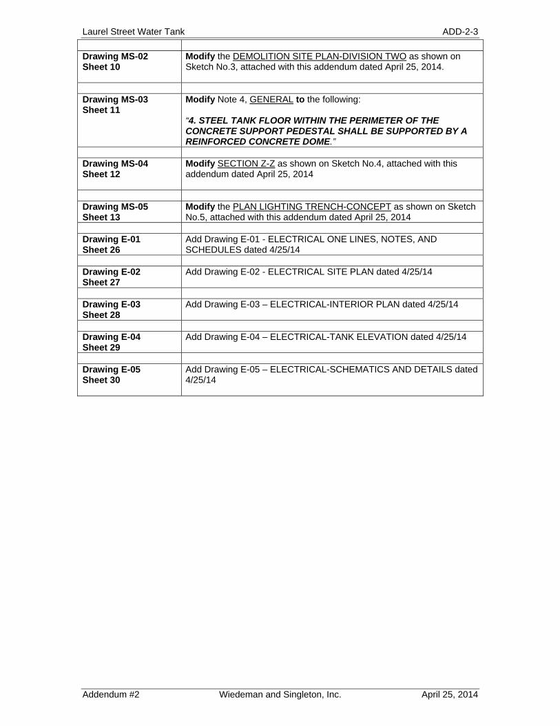
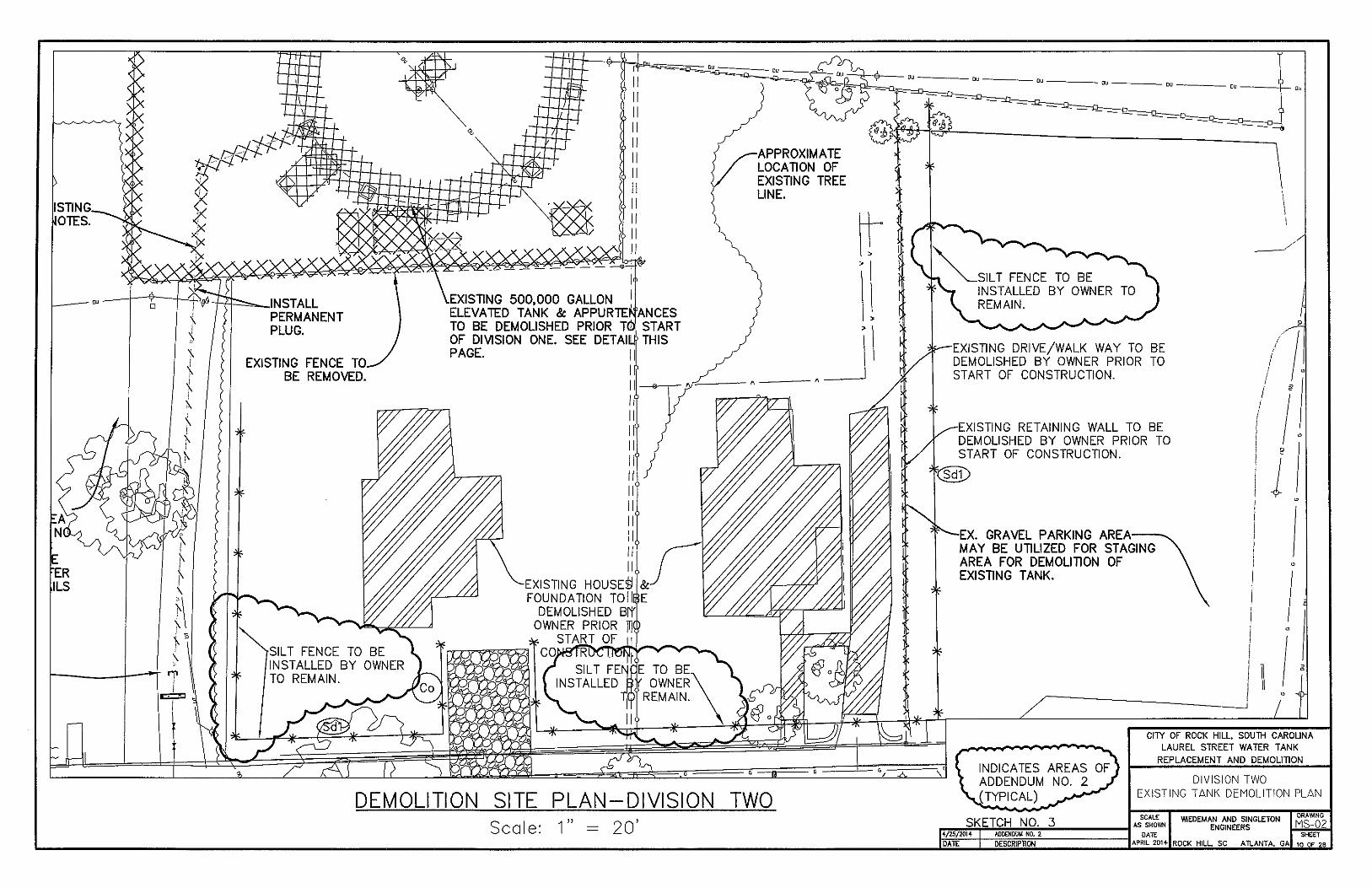
Drawing MS-02 Sheet 10
Modify the DEMOLITION SITE PLAN-DIVISION TWO as shown on Sketch No.3, attached with this addendum dated April 25, 2014.
Drawing MS-03 Sheet 11
Modify Note 4, GENERAL to the following: “4. STEEL TANK FLOOR WITHIN THE PERIMETER OF THE CONCRETE SUPPORT PEDESTAL SHALL BE SUPPORTED BY A REINFORCED CONCRETE DOME.”
Drawing MS-04 Sheet 12
Modify SECTION Z-Z as shown on Sketch No.4, attached with this addendum dated April 25, 2014
Drawing MS-05 Sheet 13
Modify the PLAN LIGHTING TRENCH-CONCEPT as shown on Sketch No.5, attached with this addendum dated April 25, 2014
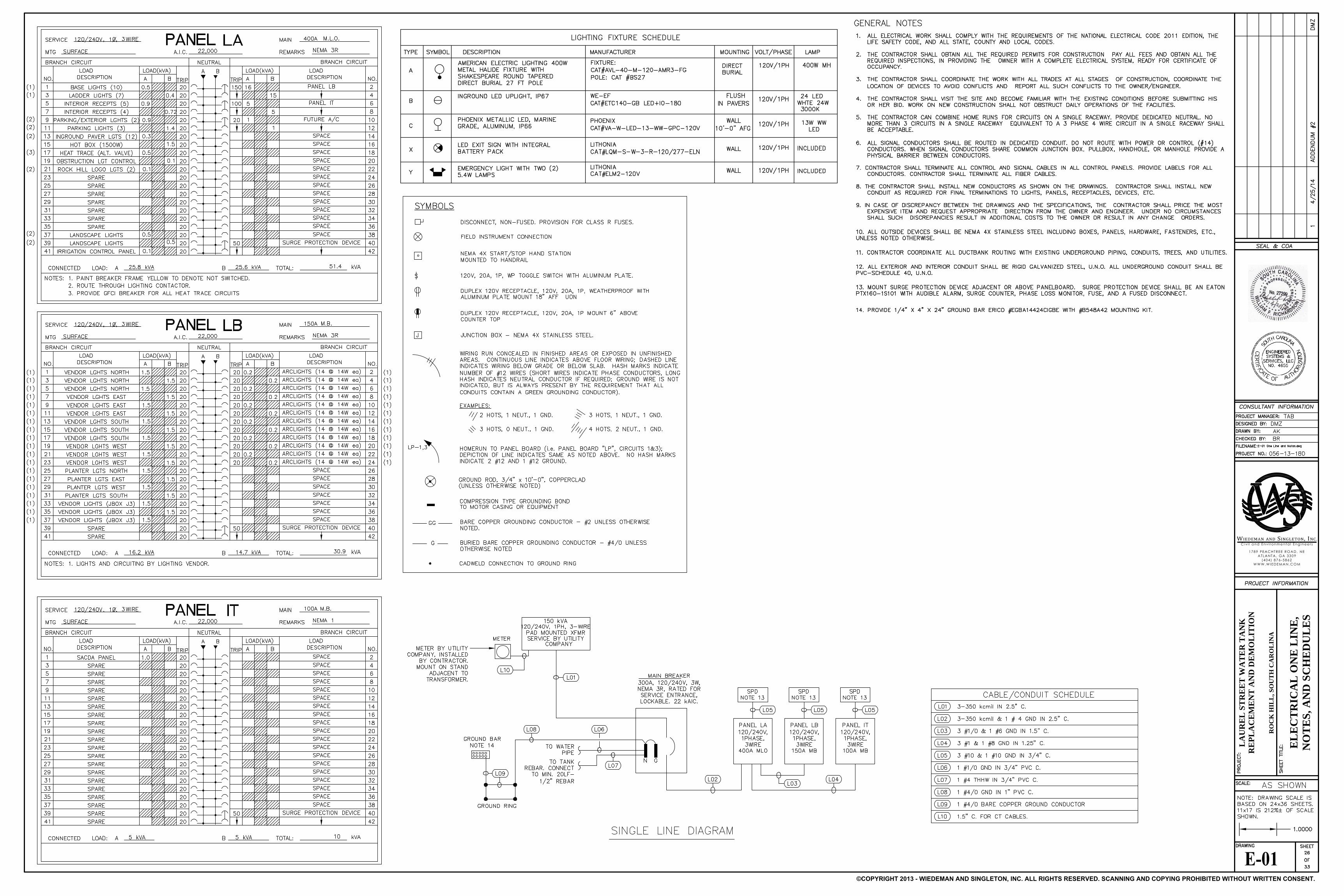
Drawing E-01 Sheet 26
Add Drawing E-01 - ELECTRICAL ONE LINES, NOTES, AND SCHEDULES dated 4/25/14
Drawing E-02 Sheet 27
Add Drawing E-02 - ELECTRICAL SITE PLAN dated 4/25/14
Drawing E-03 Sheet 28
Add Drawing E-03 – ELECTRICAL-INTERIOR PLAN dated 4/25/14
Drawing E-04 Sheet 29
Add Drawing E-04 – ELECTRICAL-TANK ELEVATION dated 4/25/14
Drawing E-05 Sheet 30
Add Drawing E-05 – ELECTRICAL-SCHEMATICS AND DETAILS dated 4/25/14

LAUREL STREET WATER TANK SECTION 03 45 00 CITY OF ROCK HILL PLANT PRECAST ARCHITECTURAL CONCRETE
Wiedeman and Singleton, Inc. Add No.2, Page 1 of 7
SECTION 03 45 00
PLANT PRECAST ARCHITECTURAL CONCRETE
PART 1 GENERAL
1.1 SCOPE
A. Provide plant-precast architectural concrete Work shown and specified.
1.2 REFERENCES
A. American Concrete Institute (ACI.) 1. ACI 318 – “Building code Requirements for Reinforced Concrete.” 2. ACI 533 – “Guide for Precast Concrete Wall Panels.”
B. American Society for Testing and Materials (ASTM). 1. A-36 – “Specification for Carbon Structural Steel.” 2. A-123 – “Steel Products.” 3. A-153 – “Specification for Zinc Coating (Hot Dip) on iron and Steel Hardware.” 4. A-185 – “Specification for Steel Welded Wire Fabric, Plain, for Concrete
Reinforcement.” 5. A-283 – “Specification for Low and Intermediate Tensile Strength Carbon Steel
Plates.” 6. A-307 – “Specification for Carbon Steel Bolts and Studs 60,000 PSI Tensile
Strength.” 7. A-325 – “Specification for Structural Bolts, Steel, Heat Treated, 120/105 ksi
Minimum Tensile Strength.” 8. A-496 – “Specification for Steel Wire, Deformed, for Concrete.” 12. A-563 – “Specification for Carbon and alloy Steel Nuts.” 13. A-572 – “Specification for High-Strength Low-Alloy Columbium-Vanadium
Structural 14. A-615 – “Specification for Deformed and Plain Billet-Steel Bars for Concrete
Reinforcement.” 15. A-666 – “Specification for Austenitic Stainless Steel, Sheet, Strip, Plate, and Flat
Bar.” 16. A-767 – “Specification for Zinc-Coated (Galvanized) Steel Bars for Concrete
Reinforcement.” 17. C-33 – “Specification for Concrete Aggregates.” 18. C-150 – “Specification for Portland Cement.” 19. C-260 – “Specification for Air-Entraining Admixtures for Concrete.” 20. C-404 – “Specification for Aggregates for Masonry Grout.” 21. C-494 – “Specification for Chemical Admixtures for Concrete.” 22. C-979 – “Specification for Pigments for Integrally Colored Concrete.” 23. C-1107– “Specification for Packaged Dry, Hydraulic-Cement Grout (Nonshrink).”
C. American Welding Society (AWS) 1. AWS D1.1 – “Structural Welding Code.”

LAUREL STREET WATER TANK SECTION 03 45 00 CITY OF ROCK HILL PLANT PRECAST ARCHITECTURAL CONCRETE
Wiedeman and Singleton, Inc. Add No.2, Page 2 of 7
D. Concrete Reinforcing Steel Institute (CRSI). 1. “Manual of Standard Practice.”
1.3 SYSTEM DESCRIPTION
A. Engineering calculations sealed by a Professional Engineer licensed to practice in South Carolina shall be provided. Comply with minimum design loads per IBC 2012 and ASCE 7.
1.4 SUBMITTALS
A. Product Data: Submit product data for manufactured materials and products.
B. Shop Drawing 1. Show in-place location, fabrication details, plans, elevations, anchorages,
reinforcement, connection details and methods, dimensions, finishes, jointing, sealant, relationships to adjacent materials, and erection and placement.
2. Show identification marks, coordinated to Shop Drawings, and date of manufacture on all units to facilitate hauling and erection.
3. Setting diagrams, templates, instructions and directions as required for installation. 4. Test results indicating the units meet specification requirements and proof of plant
certification.
C. Provide color and texture range samples (3” x 3” minimum) for approval prior to production. Manufacturing facility must be accessible for inspection.
D. Mix Design(s): Proposed concrete mix design for each type and color of concrete mix required including backup mix. Minimum 6,500 psi at 30 days.
E. Certifications: 1. Fabricator’s certification from APA (Architectural Precast Association) or PCI
(Precast/Prestress Concrete Institute) with A1 designation (AT does not qualify).
1.5 QUALITY ASSURANCE
A. Fabricator’s Qualifications: Firm shall have a minimum of ten (10) years experience in producing units similar to those required for this Project, with sufficient production capacity to produce and deliver required units without causing delay in Work. 1. Fabricating plant shall be presently certified by the following:
a. Architectural Precast Association (APA). b. Precast/Prestressed Concrete Institute (PCI) A1 designation.
B. Installer’s Qualifications: Installer shall have a record of at least five (5) years of successful installation of units similar to those required for this Project.
C. Applicable Standards: As specified under Paragraph 1.2 References.
D. Production Samples or Mock-ups: 1. Provide color and texture range samples for approval prior to production start.

LAUREL STREET WATER TANK SECTION 03 45 00 CITY OF ROCK HILL PLANT PRECAST ARCHITECTURAL CONCRETE
Wiedeman and Singleton, Inc. Add No.2, Page 3 of 7
2. Provide sample of production units (36” minimum length) for job site assembly with masonry sample panels for final review by the Owner and Engineer before fabrication.
1.6 DELIVERY, STORAGE, AND HANDLING
A. Deliver units to the Project site in such quantities and at such times to ensure continuity of installation.
B. Avoid job site storage. When job site storage is required store in a manner to prevent physical damage and so that markings are visible.
C. Lift and support only at designated lifting or supporting points as shown on Shop Drawings.
D. Provide anchorage items to be embedded in or attached to other construction without delaying the Work. Provide setting diagrams, templates, instructions and directions as required for installation.
1.7 PROJECT CONDITIONS
A. Contractor to furnish field measurements to precast fabricator.
PART 2 PRODUCTS
2.1 MAUFACTURERS
A. Approved Fabricator: 1. Lucas Concrete Products, Inc. (www.lucasconcrete.com) 2. Substitutions: Section 01 60 00 – Product Requirements
2.2 MATERIALS
A. Concrete Materials: 1. Portland Cement: ASTM C 150, Type I or III, white or gray colors to achieve
desired finish colors. Use only one brand, type, and color from the same mill. Gray cement may be used for non-exposed backup mixes.
2. Aggregates: ASTM C 33, gradation may differ to achieve desired finish characteristics. Select coarse and fine aggregate colors and screen sizes to match approved sample(s). Verify that adequate supply, from one pit or quarry, for each type of aggregate is available for the entire Project. If possible obtain entire aggregate supply prior to starting Work, or have aggregate supply held in reserve by aggregate supplier.
3. Water: Potable. Clean, clear, and free from deleterious amounts of salts, acids, alkalies, organic materials, oils, detergents, or other matter that may interfere with color, curing, or strength of concrete.
4. Admixtures: Select to be compatible in specified mix. a. Air Entraining: ASTM C 260. b. Water Reducing: ASTM C 494, Type A,B,C,F. or G.

LAUREL STREET WATER TANK SECTION 03 45 00 CITY OF ROCK HILL PLANT PRECAST ARCHITECTURAL CONCRETE
Wiedeman and Singleton, Inc. Add No.2, Page 4 of 7
c. Silica Fume: ASTM C 1240, for cement replacement for high performance concrete.
d. Coloring Agent: ASTM C 979, compatible with other concrete materials. e. Other constituents: Integral water repellents and other chemicals for which
no ASTM standard exists, shall be previously established as suitable for use in concrete or shall be shown by test or experience not to be detrimental to the concrete.
B. Formwork: 1. Provide forms with acceptable form facing materials that are non-reactive with
concrete or form release agents and will produce required finish surfaces. 2. Construct and maintain forms to produce precast concrete units of shapes, lines, and
dimensions indicated, within specified tolerances.
C. Reinforcing Materials: 1. Reinforcing Bars: ASTM A 615, Grade 40 or 60, unless otherwise required to meet
structural requirements.
D. Connection Materials: 1. Anchor Rods: ASTM A 307, carbon steel. 2. Finish for Steel Connection Materials:
a. Hot-dip galvanized (ASTM A 153) setting rods or projecting steel in masonry applications.
b. Galvanizing Repair Paint: DOD-P-21035A or SSPC-Paint 20.
E. Grout Materials: Section 03 60 00 - Grouting 1. Non-shrink Grout. 2. Cement Grout: proportions 1:2.5 by volume, minimum water for placement and
hydration.
2.3 MIXES
A. Design mixes for each type of concrete specified may be prepared by an independent testing agency or by architectural precast manufacturing plant personnel at precast fabricator’s option.
B. Proportion mixes by either testing agency trial batch or field test data methods in accordance with ACI 211.1, using materials to be used on the project, to provide normal weight concrete with properties as follows: 1. Compressive Strength: 6,000 psi when tested in accordance with ASTM C 39. 2. Maximum water cement ratio 0.40 at point of placement. 3. Add air-entrainment admixture to result in air content at point of placement
complying with ACI 533 requirements. 4. List other admixtures and recommended quantities. 5. Water absorption maximum 6% (by weight) when tested in accordance with ASTM
C 642.
C. Follow procedures similar to paragraph 2.3.B for lightweight concrete mixes.

LAUREL STREET WATER TANK SECTION 03 45 00 CITY OF ROCK HILL PLANT PRECAST ARCHITECTURAL CONCRETE
Wiedeman and Singleton, Inc. Add No.2, Page 5 of 7
2.4 FABRICATION
A. General: 1. Fabricate precast concrete units with manufacturing and testing procedures, quality
control recommendations, and dimensional tolerances as specified in ACI 533, unless more stringent requirements are shown or specified.
2. Fabricate units straight, smooth and true to size and shape, with exposed edges and corners precise and square, unless otherwise indicated.
B. Cast openings larger than 10 inches in any dimension according to locations shown on Shop Drawings. Smaller holes may be field cut when approved by Engineer.
C. Reinforcement shall comply with CRSI “Manual of Standard Practice” and ACI 318 recommendations. Reinforce architectural precast concrete units to resist handling, transportation, and erection stresses, and to comply with specified performance criteria.
D. Provide embedded anchors, inserts, steel shapes, and lifting devices as shown on Shop Drawings. Firmly hold cast items in place by jigs, strongbacks, or other approved means.
E. Comply with ACI-533 requirements for measuring, mixing, transporting, and placing concrete. Place facing mix to a thickness of the greater of 1 inch or 1.5 times the maximum aggregate size. Place back-up concrete to ensure bond with face concrete.
F. Consolidate concrete using equipment and procedures complying with ACI 533.
G. Permanently mark units with pick-up points as shown on reviewed Shop Drawings. Imprint casting date and piece mark on a surface to be concealed from view in the finished structure.
H. Cure concrete in accordance with ACI 533 requirements.
I. Discard units that are warped, cracked, broken, spalled, stained, or otherwise defective. Refer to ACI-533 for product finish requirements unless otherwise shown or specified.
J. Fabricate to tolerances listed in ACI-533.
2.5 FINISHES
A. Finish for exposed surfaces shall be acid etched finish using acid solution and application techniques to expose aggregate and surrounding matrix.
B. Finish exposed back surface of units to match face surface of units.
C. Finish unexposed surfaces of units by float finish or as-cast form finish.
2.6 SOURCE QUALITY CONTROL
A. Inspect and test architectural precast concrete in accordance with ACI 533.
B. Discard units that do not conform to requirements as shown or specified. Replace with units which meet requirements.

LAUREL STREET WATER TANK SECTION 03 45 00 CITY OF ROCK HILL PLANT PRECAST ARCHITECTURAL CONCRETE
Wiedeman and Singleton, Inc. Add No.2, Page 6 of 7
PART 3 EXECUTION
3.1 EXAMINATION
A. Furnish field dimensions to fabricator as required.
B. Examine substrates and conditions for compliance with requirements for installation, tolerances, true and level bearing surfaces, and other conditions affecting performance of architectural precast concrete units. Do not proceed with installation until unsatisfactory conditions have been corrected.
C. Do not install units until supporting structure has been completed and has attained adequate strength to support units without damage to structure.
3.2 ERECTION
A. Erection shall be by persons experienced and trained in placement and securing of architectural precast concrete units. Install per manufacturer’s recommendations.
B. Erect level, plumb, and true to line. Do not allow cumulative dimensional errors to develop. Adjustments such as shimming which would place additional stress on units will not be permitted. Adhere to dimensional tolerances in accordance with ACI recommendations. Erect and secure in a manner to prevent damage to unit or units in place. Replace any damaged units.
C. Lift and handle precast using lift points and embeds as shown on precast shop drawings.
D. Erection Tolerances: 1. Erect within tolerances listed in ACI-533. 2. Erect to conform with structure tolerances listed in ACI-533. 3. Where two stage joint seal is required, sequence with sealant applicator to ensure
that sealant, gaskets, and similar items required for interior side seal are installed concurrently with installation of precast units.
E. Jointing 1. Joint size and locations.
a. All masonry joints shall be 3/8” or as recommended by manufacturer. b. Location as shown on shop drawings. c. At control and expansion joints, unless otherwise shown.
2. Joint Materials – as follows, unless otherwise recommended by manufacturer: a. Mortar, Type N, ASTM C 270 b. Color match mortar. c. Use a full bed of mortar at all bed joints. d. Flush vertical joints full with mortar e. Leave all joints with exposed tops or under relieving angles open for sealant. f. Leave head joints in coping and projecting components open for sealant.
3. Joint Sealants: As specified in Section 07 90 00. 4. Setting
a. Fill dowel holes and anchor slots completely with mortar or non-shrink grout.
LAUREL STREET WATER TANK SECTION 03 45 00 CITY OF ROCK HILL PLANT PRECAST ARCHITECTURAL CONCRETE
Wiedeman and Singleton, Inc. Add No.2, Page 7 of 7
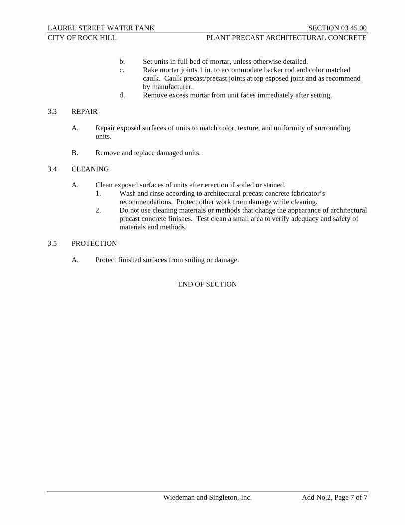
b. Set units in full bed of mortar, unless otherwise detailed. c. Rake mortar joints 1 in. to accommodate backer rod and color matched
caulk. Caulk precast/precast joints at top exposed joint and as recommend by manufacturer.
d. Remove excess mortar from unit faces immediately after setting.
3.3 REPAIR
A. Repair exposed surfaces of units to match color, texture, and uniformity of surrounding units.
B. Remove and replace damaged units.
3.4 CLEANING
A. Clean exposed surfaces of units after erection if soiled or stained. 1. Wash and rinse according to architectural precast concrete fabricator’s
recommendations. Protect other work from damage while cleaning. 2. Do not use cleaning materials or methods that change the appearance of architectural
precast concrete finishes. Test clean a small area to verify adequacy and safety of materials and methods.
3.5 PROTECTION
A. Protect finished surfaces from soiling or damage.
END OF SECTION

LAUREL STREET WATER TANK SECTION 31 62 16 CITY OF ROCK HILL STEEL PILES
Wiedeman and Singleton, Inc. Add No.2, Page 1 of 6
SECTION 31 62 16
STEEL HP PILES
PART 1 GENERAL
1.1 SUMMARY
A. The work covered by these specifications consist of furnishing all labor, equipment and materials for the installation of steel HP piles for the Laurel Street Elevated Water Tank. This specification provides the minimum requirements and performance criteria for steel HP piles. The Contractor is responsible for all aspects of the design and construction of the pile foundations and shall meet or exceed the requirements specified herein.
1.2 UNIT PRICES - MEASUREMENT AND PAYMENT
A. No separate payment will be made for the work in this section. All costs including index piles, production piles, splices, geotechnical monitoring and any other work required for the complete installation shall be included in the Lump Sum cost for the tank.
1.3 REFERENCES
A. ASTM International: 1. ASTM A6/A6M - Standard Specification for General Requirements for Rolled
Structural Steel Bars, Plates, Shapes, and Sheet Piling. 2. ASTM A36/A36M - Standard Specification for Carbon Structural Steel. 3. ASTM A572 - Standard Specification for High-Strength Low-Alloy Columbium-
Vanadium Structural Steel
B. American Welding Society: 1. AWS D1.1 - Structural Welding Code - Steel.
1.4 PERFORMANCE REQUIREMENTS
A. The Contractor shall be required, at his own expense, to confirm the design load capacity by driving a minimum of two index piles. The capacity of index piles should be verified by use of pile driving analyzer testing. 1. At the Contractor’s option, these piles may be used as permanent piles in the tank
foundation, in which case the piles shall be of the correct size and of sufficient length to cut off at the proper grade.
B. Each pile shall be driven to the proper depth to obtain a safe bearing value that exceeds the design requirements; or shall be driven to refusal in rock (i.e., end bearing pile).
C. The load per pile shall be designed by the Tank Contractor and submitted to the Engineer for review. Signed and sealed pile capacity calculations shall be provided by the Professional Engineer licensed in the State of South Carolina responsible for the foundation design for the Tank Contractor.
LAUREL STREET WATER TANK SECTION 31 62 16 CITY OF ROCK HILL STEEL PILES
Wiedeman and Singleton, Inc. Add No.2, Page 2 of 6
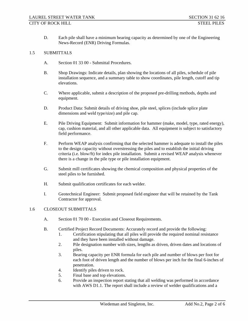
D. Each pile shall have a minimum bearing capacity as determined by one of the Engineering News-Record (ENR) Driving Formulas.
1.5 SUBMITTALS
A. Section 01 33 00 - Submittal Procedures.
B. Shop Drawings: Indicate details, plan showing the locations of all piles, schedule of pile installation sequence, and a summary table to show coordinates, pile length, cutoff and tip elevations.
C. Where applicable, submit a description of the proposed pre-drilling methods, depths and equipment.
D. Product Data: Submit details of driving shoe, pile steel, splices (include splice plate dimensions and weld type/size) and pile cap.
E. Pile Driving Equipment: Submit information for hammer (make, model, type, rated energy), cap, cushion material, and all other applicable data. All equipment is subject to satisfactory field performance.
F. Perform WEAP analysis confirming that the selected hammer is adequate to install the piles to the design capacity without overstressing the piles and to establish the initial driving criteria (i.e. blow/ft) for index pile installation. Submit a revised WEAP analysis whenever there is a change in the pile type or pile installation equipment.
G. Submit mill certificates showing the chemical composition and physical properties of the steel piles to be furnished.
H. Submit qualification certificates for each welder.
I. Geotechnical Engineer: Submit proposed field engineer that will be retained by the Tank Contractor for approval.
1.6 CLOSEOUT SUBMITTALS
A. Section 01 70 00 - Execution and Closeout Requirements.
B. Certified Project Record Documents: Accurately record and provide the following: 1. Certification stipulating that all piles will provide the required nominal resistance
and they have been installed without damage. 2. Pile designation number with sizes, lengths as driven, driven dates and locations of
piles. 3. Bearing capacity per ENR formula for each pile and number of blows per foot for
each foot of driven length and the number of blows per inch for the final 6-inches of penetration.
4. Identify piles driven to rock. 5. Final base and top elevations. 6. Provide an inspection report stating that all welding was performed in accordance
with AWS D1.1. The report shall include a review of welder qualifications and a

LAUREL STREET WATER TANK SECTION 31 62 16 CITY OF ROCK HILL STEEL PILES
Wiedeman and Singleton, Inc. Add No.2, Page 3 of 6
report on visual inspection of the welds on the job site. The inspection shall be signed by a Certified Welding Inspector (CWI) retained by the Contractor.
7. Provide PDA report.
1.7 QUALIFICATIONS
A. Steel pile Contractor shall be approved by Owner and Engineer. The Tank Contractor shall submit steel pile Contractor qualification package to the Engineer. The steel pile Contractor shall meet the following minimum requirements: 1. Company specializing in performing work of this section with minimum 5 years
documented experience with at least 10 successful installations of the same general type and nature of the piles.
2. The superintendent proposed for the work shall have a minimum of 5 years experience in pile driving and shall be experienced in similar pile driving operations.
B. Monitor pile driving operations by Geotechnical Engineer experienced in this Work and licensed in the State of South Carolina.
C. Welders Certificates: Certify welders employed on the Work, verifying AWS qualification within previous 12 months, for the type and nature of the welding that will be performed.
1.8 Geotechnical Investigations:
A. A Report of Geotechnical Investigation has been prepared for this project. See Section 02 32 00, and Appendix for additional information.
1.9 PRE-INSTALLATION MEETINGS
A. Pre-installation meeting required with Owner, Engineer, Tank Contractor, steel pile Contractor and Geotechnical Engineer.
B. Contractor shall schedule with all parties. 1. Convene minimum one week prior to commencing Work of this section.
1.10 DELIVERY, STORAGE, AND HANDLING
A. Section 01 60 00 - Product Requirements: Requirements for transporting, handling, storing, and protecting products.
1.11 SCHEDULING
A. Section 01 30 00 - Administrative Requirements and 01 32 16 - Construction Progress Schedule.
PART 2 PRODUCTS
2.1 MATERIALS
A. Piles:

LAUREL STREET WATER TANK SECTION 31 62 16 CITY OF ROCK HILL STEEL PILES
Wiedeman and Singleton, Inc. Add No.2, Page 4 of 6
1. Pile size shall be as required by the foundation design. 2. Piles shall be ASTM A572 Grade 50.
B. Splices: Shall be made with steel splice plates fully welded to each flange of the pile. 1. Splice plates shall be sized by the pile design engineer. 2. Type and size of welds shall be designed by the pile design engineer.
C. Accessories: Driving shoes required.
PART 3 EXECUTION
3.1 EXAMINATION
A. Section 01 30 00 - Administrative Requirements regarding verification of existing conditions before starting work.
3.2 PREPARATION
A. Use driving method to limit ground operations due to pile installations, which will not cause damage to nearby structures. Vibration shall be monitored using seismographs for all buildings and other structures within 200 feet of pile driving. A preconstruction survey shall also be conducted on all nearby facilities. The survey shall consist of visual inspection and documentation of the condition of the existing facility. Contractor is responsible for all vibration monitoring and reporting and for repairing and cost of repairing damage to adjacent facilities.
B. Protect structures including overhead and buried utilities near the Work, from damage.
C. Prepare to place piles from existing site elevations. When piles are located in an area where site grading is required, the piles shall not be driven until the grading is complete.
3.3 PILE HAMMER
A. Changes in the selected driving equipment will not be allowed after the equipment has been approved except as directed by the Engineer.
B. Keep hammer in good mechanical condition.
C. Operate hammer at speed and pressure recommended by manufacturer.
D. When energy per blow is less than 80 percent of rated energy per blow as specified by manufacturer of pile hammer, make necessary repairs to improve energy output to value of at least 80 percent of rated energy per blow, or replace pile hammer.
3.4 INSTALLATION
A. Drive piles only in presence of the Geotechnical Engineer who shall be present during all pile driving operations to observe the work. Piles not installed in the presence of the Geotechnical Engineer will not be accepted.

LAUREL STREET WATER TANK SECTION 31 62 16 CITY OF ROCK HILL STEEL PILES
Wiedeman and Singleton, Inc. Add No.2, Page 5 of 6
B. Provide legible markings on each pile in 1-foot increments, starting at the tip, with enlarged numerals to indicate the length of the pile at 5-foot intervals.
C. Use rigid frame, fixed lead type driving equipment capable of supporting pile firmly in vertical position or to required batter.
D. Align top of pile normal to driving force of pile, hammer and leads to minimize bowing of pile during impact of hammer ram.
E. Where groups of piles are required, drive center pile of group first and then drive remaining piles in group progressing outward from center.
F. Drive piles to minimum tip penetration and to required driving resistance. 1. Take corrective action, when required, to prevent observable impact bowing of pile
at final driving resistance.
G. When driving resistance prohibits advancing pile to required minimum tip penetration, spud, jet, jet and drive, or use other means as necessary to advance pile to required minimum tip penetration. 1. Then drive pile to required resistance. 2. After jetting pile, re-drive adjacent piles to required resistance.
H. Pre-drilling or pre-augering hole of maximum diameter 2 inches smaller than pile flange dimension may be used to advance pile to penetration no deeper than required minimum tip penetration. 1. Then drive pile to required resistance.
I. Protect pile head during driving, using cap-block cushion consisting of alternate plates of phenolic laminate and aluminum designed to prevent damage to piles while transmitting required hammer energy to pile top, with full bearing on pile butt for even distribution of hammer blow.
J. Deliver hammer blows to central axis of pile.
K. When driving is interrupted before refusal, drive an additional 12 inches before resuming recording of performance data.
L. Re-drive piles which have lifted due to driving adjacent piles, or by soil uplift.
M. Do not damage piles during driving operations.
N. Cut off tops of piles to required elevations and cap. 1. The head of each pile shall be capped with a steel plate 1” thick welded to the pile
with 5/16” filler weld. 2. The pile head shall be smooth, perpendicular to the axis of the pile and shall fit the
plate snugly.
3.5 WELDING AND SPLICING
A. Perform welding in accordance with AWS D1.1 for shielded metal arc welding.

LAUREL STREET WATER TANK SECTION 31 62 16 CITY OF ROCK HILL STEEL PILES
Wiedeman and Singleton, Inc. Add No.2, Page 6 of 6
B. Only use welders qualified in accordance with AWS D1.1.
C. Splices shall be made with steel splice plates fully welded to each flange of the pile.
D. Pile ends shall be separated 1/8” and the entire periphery of the pile joint shall then be welded.
3.6 ERECTION TOLERANCES
A. Section 01 40 00 - Quality Requirements: Tolerances.
B. Maximum Variation from Vertical for Plumb Piles: 1 in 48.
C. Maximum Out-of-Position: 2 inches.
D. Maximum Variation in Centerline after Splicing: 3/8 inch in 40 feet for undriven portion.
3.7 PILE DRIVING ANALYZER TESTING
A. Prior to installation of production piles, capacity of index piles should be verified by use of pile driving analyzer testing.
B. The final driving criteria (pile length and number of blows per foot) shall be established based on PDA results.
C. PDA testing shall be performed by a qualified engineering consultant. Submit documentation that the PDA Consultant has successfully completed at least 5 PDA testing projects within the last 3 years of a scope and complexity similar to that anticipated for this project. Documentation should include the General Contractor and Owner’s name and current contact information with descriptions of each past project.
D. The PDA Consultant shall perform analysis of the PDA raw data and within 7 calendar days after field testing is complete submit a PDA report. The report shall be signed and sealed by the consultant.
3.8 FIELD QUALITY CONTROL
A. Section 01 40 00 - Quality Requirements: Field inspecting, testing, adjusting, and balancing.
B. All work shall be continuously monitored by a Geotechnical Engineer licensed in South Carolina. 1. The contractor is responsible for hiring and coordinating the services of the
Geotechnical Engineer.
C. Provide additional piles or replace piles to conform to specified requirements at no additional expense to Owner.
END OF SECTION

LAUREL STREET WATER TANK SECTION 31 63 16 CITY OF ROCK HILL AUGER CAST GROUT PILES
Wiedeman and Singleton, Inc. Add No. 2, Page 1 of 6
SECTION 31 63 16
AUGER CAST GROUT PILES
PART 1 GENERAL
1.1 Summary
A. The work covered by these specifications consist of furnishing all labor, equipment and materials for the placing of augered piles for the Laurel Street Elevated Water Tank. This specification provides the minimum requirements and performance criteria for auger cast grout piles. The Contractor is responsible for all aspects of the design and construction of the pile foundations and shall meet or exceed the requirements specified herein.
B. The intent of this project is to install augered piles in locations as required by the design of the Tank Contractor.
C. Piling shall be installed by rotating a continuous flight hollow-shaft auger through the soil and shall be advanced to refusal in rock material. Rock material is defined as a penetration rate of one foot (or less) per minute using a drive box having a minimum dead weight of 5000 pounds and a torque of 20,000 foot-pounds.
D. The load per pile shall be designed by the Tank Contractor and submitted to the Engineer for review. Signed and sealed pile capacity calculations shall be provided by the Professional Engineer licensed in the State of South Carolina responsible for the foundation design for the Tank Contractor.
E. A single test pile shall be tested in accordance with ASTM D-1143 to 200% of the single pile design load. The Contractor shall submit a proposed testing plan in accordance with ASTM D-1143 for review and acceptance by the Engineer. The allowable design load shall be defined as 50% of the ultimate load as determined by the Brinch Hansen 90% or Butler Hoy methods, in accordance with the IBC.
F. Independent Testing and Inspection Agency: The Contractor shall retain a geotechnical engineer to document, monitor, and observe test pile and load test, probe pile, and production pile work. The geotechnical engineer and auger cast pile Contractor shall submit field reports and test results required by ASTM D-1143 for pile load tests, pile installations, and grout testing and inspection.
G. Submit the proposed geotechnical engineer for review and approval with the testing plan submittal. The geotechnical engineer shall be experienced in the testing and installation of auger cast grout pile foundations. They shall have been involved in at least 8 different auger cast pile projects in the last 5 years, and shall have experience in testing, inspecting, reporting and specifying and recommending auger cast piles for similar subsurface conditions. The test pile shall not be used as a production pile. Probe piles may be used at the discretion of the Contractor, but are not required.

LAUREL STREET WATER TANK SECTION 31 63 16 CITY OF ROCK HILL AUGER CAST GROUT PILES
Wiedeman and Singleton, Inc. Add No. 2, Page 2 of 6
1.2 Contractor Qualifications
A. Auger cast pile Contractor shall be approved by Owner and Engineer. The Tank Contractor shall submit auger cast pile Contractor qualification package to the Engineer. The auger cast pile Contractor shall certify that: 1. Contractor has technical qualifications, experience, trained personnel and facilities to install
auger cast grout concrete as specified. Approval will not be given, however, where an experience record is one of unsatisfactory performance.
2. Contractor has installed auger cast grout piles on five (5) installations similar and equivalent to this project in the last 3 years. Submit list of installations.
1.3 Submittals:
A. Provide submittals on all materials to be used in pile installation, including but not limited to, grout mix design, admixtures, reinforcing shop drawings, etc.
B. Provide information such as pile drilling equipment (gear box weight and torque), grout pump and pressure gage calibration reports, pile installation recorder (PIR) calibration reports, test plan and pile installation procedures.
C. Submit plan for installing augered piles. 1. Coordinate with dewatering and excavation plans. 2. Provide order in which piles will be installed.
1.4 Location of Piles:
A. Piles shall be located as designed by the Tank Contractor and submitted for review by the Engineer.
B. Pile centers shall be located to an accuracy of plus or minus 3 inches.
C. Piles shall not be placed closer than 3 pile diameters (center to center) until the grout in the piles has set for a minimum of 24 hours.
D. In locations where there are no concrete slabs or other means of distributing the load of the piling placement equipment, the points where this concentrated load is applied to the soil shall be at least ten feet away from the pile location.
E. This will prevent the weight of the piling placement equipment from compressing or shearing the soil, which may, in turn, squeeze in the top of the pile.
1.5 Pile Tops:
A. Where the piles cutoff is near the surface or above the bottom of the excavation, metal sleeves or casing of the proper diameter and at least 18 inches in length shall be placed around the pile tops. (Special conditions may require metal sleeves of additional length.)
LAUREL STREET WATER TANK SECTION 31 63 16 CITY OF ROCK HILL AUGER CAST GROUT PILES
Wiedeman and Singleton, Inc. Add No. 2, Page 3 of 6
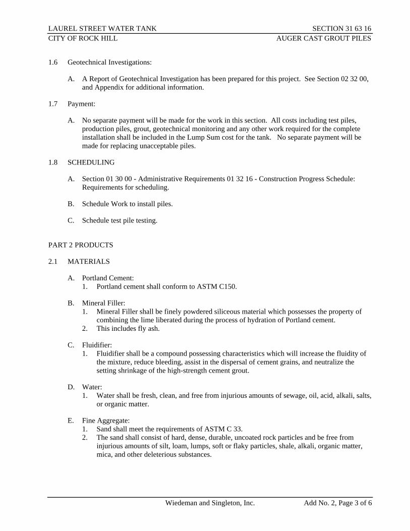
1.6 Geotechnical Investigations:
A. A Report of Geotechnical Investigation has been prepared for this project. See Section 02 32 00, and Appendix for additional information.
1.7 Payment:
A. No separate payment will be made for the work in this section. All costs including test piles, production piles, grout, geotechnical monitoring and any other work required for the complete installation shall be included in the Lump Sum cost for the tank. No separate payment will be made for replacing unacceptable piles.
1.8 SCHEDULING
A. Section 01 30 00 - Administrative Requirements 01 32 16 - Construction Progress Schedule: Requirements for scheduling.
B. Schedule Work to install piles.
C. Schedule test pile testing.
PART 2 PRODUCTS
2.1 MATERIALS
A. Portland Cement: 1. Portland cement shall conform to ASTM C150.
B. Mineral Filler: 1. Mineral Filler shall be finely powdered siliceous material which possesses the property of
combining the lime liberated during the process of hydration of Portland cement. 2. This includes fly ash.
C. Fluidifier: 1. Fluidifier shall be a compound possessing characteristics which will increase the fluidity of
the mixture, reduce bleeding, assist in the dispersal of cement grains, and neutralize the setting shrinkage of the high-strength cement grout.
D. Water: 1. Water shall be fresh, clean, and free from injurious amounts of sewage, oil, acid, alkali, salts,
or organic matter.
E. Fine Aggregate: 1. Sand shall meet the requirements of ASTM C 33. 2. The sand shall consist of hard, dense, durable, uncoated rock particles and be free from
injurious amounts of silt, loam, lumps, soft or flaky particles, shale, alkali, organic matter, mica, and other deleterious substances.

LAUREL STREET WATER TANK SECTION 31 63 16 CITY OF ROCK HILL AUGER CAST GROUT PILES
Wiedeman and Singleton, Inc. Add No. 2, Page 4 of 6
3. If washed, the washing method shall be such as will not remove desirable fines, and the sand shall subsequently be permitted to drain until the residual-free moisture is reasonably uniform and stable.
4. The sand shall be well-graded from fine to coarse, with fineness modulus between 1.40 and 3.40.
5. The fineness modulus is defined as the total divided by 100 of the cumulative percentages retained on U.S. Standard Sieve Nos. 16, 30, 50 and 100.
F. High-Strength Grout: 1. The grout used to fill the holes shall consist of a mixture of Portland cement, fluidifier, sand
and water so proportioned and mixed as to provide a grout capable of maintaining the solids in suspension without appreciable water gain, yet which may be placed without difficulty, and which will laterally penetrate and fill any voids in the foundation material.
2. Mineral Filler may be added to the above mix in lieu of a small percentage of the Portland cement at the piling contractor’s option.
3. The materials shall be so proportioned as to provide a hardened grout having a minimum compressive strength of 4000 psi at 28 days.
4. The grout mix shall be tested by making one set of 2” cubes for each day during which piles are placed.
5. A set of cubes shall consist of 2 cubes to be tested at 7 days, and 2 cubes to be tested at 28 days.
6. Test cubes shall be made and tested in accordance with ASTM C 109, with the exception that the grout should be restrained from expansion by a top plate.
2.2 EQUIPMENT:
A. Augering Equipment: 1. The hole through which the high-strength grout is pumped during the placement of the pile
shall be located at the bottom of the auger head below the bar containing the cutting teeth. 2. The auger flighting shall be continuous from the auger head to the top of auger with no gaps
or other breaks. 3. The pitch of the auger flighting shall not exceed 9 inches. 4. Augers over 40 feet in length shall contain a middle guide. 5. The piling leads should be prevented from rotating by a stabilizing arm.
B. Mixing and Pumping of High-Strength Cement Grout: 1. Only approved pumping, continuous mixing and agitating equipment shall be used in the
preparation and handling of the grout. 2. All oil or other rust inhibitors shall be removed from mixing drums and grout pumps. 3. If ready-mix grout is used, an agitating storage tank of sufficient size shall be used between
the ready-mix truck and the grout pump to insure a homogeneous mix and continuity in the pumping operations.
4. All materials shall be such as to produce a homogeneous grout of the desired consistency. 5. If there is a lapse in the operation, the grout shall be recirculated through the pump. 6. The grout pump shall be calibrated prior to initiation of production piles, and as often as
necessary throughout the installation of the piles as deemed necessary by the geotechnical engineer.
7. The minimum grout head shall be five (5) feet.

LAUREL STREET WATER TANK SECTION 31 63 16 CITY OF ROCK HILL AUGER CAST GROUT PILES
Wiedeman and Singleton, Inc. Add No. 2, Page 5 of 6
8. The grout filling operation shall continue without interruption until the auger is extracted completely from the ground.
9. The grout pump shall be a positive displacement piston type pump capable of developing displacing pressures at the pump not less than 350 psi.
10. The absolute minimum volume of grout placed in the hole shall at least 1.15 times the volume of the augered hole. a. Piles less than this minimum will not be accepted and shall be replaced.
11. Grout volume shall be measured and reported to the Engineer.
PART 3 EXECUTION
3.1 EXAMINATION
A. Section 01 30 00 - Administrative Requirements: Verification of existing conditions before starting work.
3.2 PREPARATION
A. Protect structures near the Work, from damage.
B. Prepare site and working area prior to augering piles.
3.3 FIELD QUALITY CONTROL
A. Section 01 70 00 - Execution and Closeout Requirements: Field inspecting and testing.
B. The Contractor shall be responsible for coordinating the proper equipment to completely install the auger cast piles. 1. This includes the crane and rigging required for the maximum depth auger cast pile required
to achieve the design load. 2. No additional or separate payment will be allowed for mobilizing additional equipment.
C. The test pile report shall be submitted to the Owner and Engineer for review. The Contractor shall allow the Engineer time to review, comment and accept this report prior to commencing with auger cast pile production.
D. Document pile depth for Record Drawing purposes.
E. Submit a pile installation report to the Engineer and Owner for each pile no later than three days after the installation is complete. 1. This report shall contain a certification that all piles were properly installed and have a load
capacity equal to or greater than the design capacity. 2. This report shall be stamped by a registered professional engineer licensed in the State of
South Carolina.
F. Unacceptable Piles: Piles that fail tests, are placed out of position, are below cut-off elevations, or are damaged.

LAUREL STREET WATER TANK SECTION 31 63 16 CITY OF ROCK HILL AUGER CAST GROUT PILES
Wiedeman and Singleton, Inc. Add No. 2, Page 6 of 6
G. Lateral drift (out of plumbness) shall not exceed one (1”) inch in any 10 foot vertical section. Maximum total lateral drift shall not exceed four inches (0’-4”).
H. Provide additional piles or replace piles to conform to specified requirements.
3.4 Clean Up
A. After the test pile is loaded it shall be abandoned by removing the top 3 feet of the test pile and backfilling to 95% Standard Proctor.
B. All debris from excavation of objectionable material, removal of obstructions, and any material not to remain as part of the construction are to be removed and disposed of by the auger cast pile Contractor in a legal manner at no additional cost to the Owner.
C. The site shall be cleaned at frequent intervals and no material shall be stored on the site in a manner, which would obstruct the easy access of equipment and personnel.
END OF SECTION


535 Courtney Hodges Blvd · P O Box 1350 · Perry, GA 31069 Local: 478.987.0303 | Toll-free: 800.223.3695 | Fax: 478.987.1085 | utilityservice.com
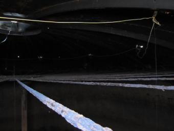
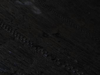
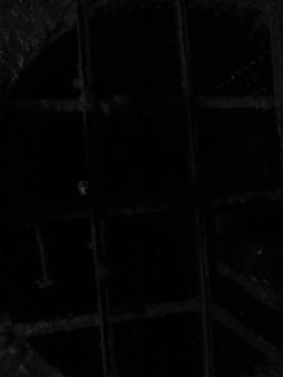
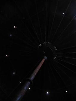
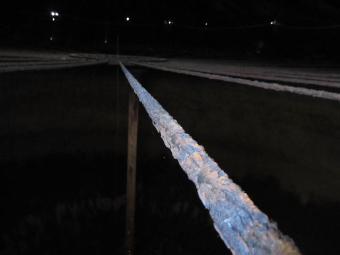
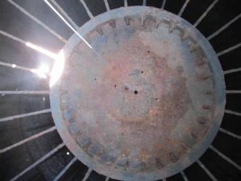
April 25, 2014 Troy Began P.E. Wiedeman and Singleton, Inc. 131 East Main St., Suite 300 Rock Hill, SC 29730 RE: City of Rock Hill, SC Laurel St. Tank Inspection Mr. Began: The Laurel St. Tank for the City of Rock Hill, SC was drained on April 17th for the purpose of verifying the interior coating and the total coverage of the coating. Paint samples were taken and given to S&ME to perform analysis of lead and asbestos. The tank was disinfected upon completion of the inspection. The interior coating was verified as 70B and super tank solution. The total coverage of the 70B coating is approximately 95% of the interior with mill thickness ranging from 20-50 mills. Please see the attached photos for verification. Sincerely, Andy Tillman Water Systems Consultant


©COPYRIGHT 2013 - WIEDEMAN AND SINGLETON, INC. ALL RIGHTS RESERVED. SCANNING AND COPYING PROHIBITED WITHOUT WRITTEN CONSENT.
EL
EC
TR
ICA
L O
NE
LIN
E,
NO
TE
S, A
ND
SC
HE
DU
LE
S
LA
UR
EL
ST
RE
ET
WA
TE
R T
AN
KR
EPL
AC
EM
EN
T A
ND
DE
MO
LIT
ION
RO
CK
HIL
L, S
OU
TH
CA
RO
LIN
A

EL
EC
TR
ICA
LSI
TE
PL
AN
LA
UR
EL
ST
RE
ET
WA
TE
R T
AN
KR
EPL
AC
EM
EN
T A
ND
DE
MO
LIT
ON
RO
CK
HIL
L, S
OU
TH
CA
RO
LIN
A

©COPYRIGHT 2013 - WIEDEMAN AND SINGLETON, INC. ALL RIGHTS RESERVED. SCANNING AND COPYING PROHIBITED WITHOUT WRITTEN CONSENT.
EL
EC
TR
ICA
L -
INT
ER
IOR
PL
AN
LA
UR
EL
ST
RE
ET
WA
TE
R T
AN
KR
EPL
AC
EM
EN
T A
ND
DE
MO
LIT
ION
RO
CK
HIL
L, S
OU
TH
CA
RO
LIN
A

NOTES:
ELEVATION
30
.0
0 F
T
MA
X H
EA
D R
AN
GE
OBSTRUCTION
LIGHT (NOTE 4)
TANK ACCESS HATCH
ACCESS TUBE HATCH
ROOF ACCESS LADDER
WITH SAFETY CLIMB
INTERIOR TANK ACCESS LADDER
WITH SAFETY CLIMB
ACCESS TUBE
FINISH GRADE EL. 671.00
12" INLET / OUTLET PIPE
10" OVERFLOW PIPE
LWL ELEV. 793.00
HWL ELEV. 823.00
©COPYRIGHT 2013 - WIEDEMAN AND SINGLETON, INC. ALL RIGHTS RESERVED. SCANNING AND COPYING PROHIBITED WITHOUT WRITTEN CONSENT.
EL
EC
TR
ICA
L -
TA
NK
EL
EV
AT
ION
LA
UR
EL
ST
RE
ET
WA
TE
R T
AN
KR
EPL
AC
EM
EN
T A
ND
DE
OM
OL
ITIO
N
RO
CK
HIL
L, S
OU
TH
CA
RO
LIN
A

©COPYRIGHT 2013 - WIEDEMAN AND SINGLETON, INC. ALL RIGHTS RESERVED. SCANNING AND COPYING PROHIBITED WITHOUT WRITTEN CONSENT.
EL
EC
TR
ICA
L -
SCH
EM
AT
ICS
AN
D D
ET
AIL
S
LA
UR
EL
ST
RE
ET
WA
TE
R T
AN
KR
EPL
AC
EM
EN
T A
ND
DE
OM
OL
ITIO
N
RO
CK
HIL
L, S
OU
TH
CA
RO
LIN
A