additional steel topics - pdhonline.com
TRANSCRIPT
PDHonline Course S218 (1 PDH)
Additional Steel Topics
2012
Instructor: Matthew Stuart, PE, SE
PDH Online | PDH Center5272 Meadow Estates Drive
Fairfax, VA 22030-6658Phone & Fax: 703-988-0088
www.PDHonline.orgwww.PDHcenter.com
An Approved Continuing Education Provider
www.PDHcenter.com PDH Course S218 www.PDHonline.org
© D. Matthew Stuart Page 2 of 11
Additional Steel Topics
D. Matthew Stuart, P.E., S.E., F.ASCE, SECB
COURSE CONTENT Additional Topics
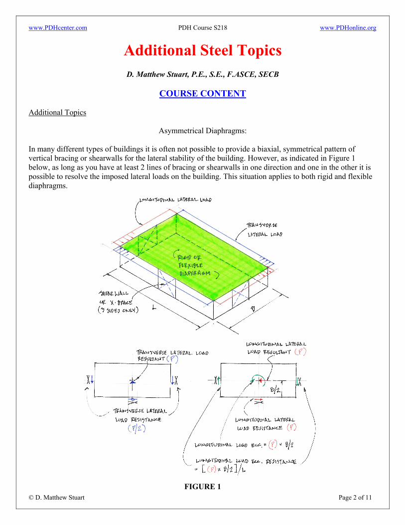
Asymmetrical Diaphragms: In many different types of buildings it is often not possible to provide a biaxial, symmetrical pattern of vertical bracing or shearwalls for the lateral stability of the building. However, as indicated in Figure 1 below, as long as you have at least 2 lines of bracing or shearwalls in one direction and one in the other it is possible to resolve the imposed lateral loads on the building. This situation applies to both rigid and flexible diaphragms.
FIGURE 1
www.PDHcenter.com PDH Course S218 www.PDHonline.org
© D. Matthew Stuart Page 3 of 11
Axial Shortening of Columns:
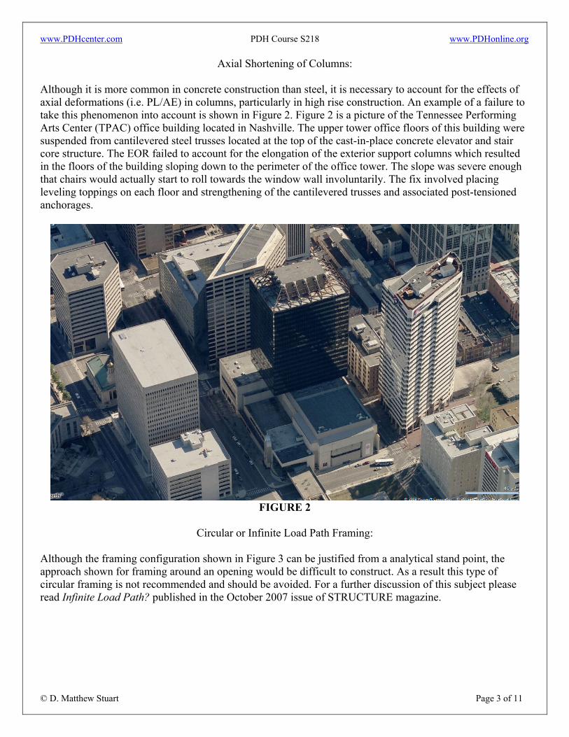
Although it is more common in concrete construction than steel, it is necessary to account for the effects of axial deformations (i.e. PL/AE) in columns, particularly in high rise construction. An example of a failure to take this phenomenon into account is shown in Figure 2. Figure 2 is a picture of the Tennessee Performing Arts Center (TPAC) office building located in Nashville. The upper tower office floors of this building were suspended from cantilevered steel trusses located at the top of the cast-in-place concrete elevator and stair core structure. The EOR failed to account for the elongation of the exterior support columns which resulted in the floors of the building sloping down to the perimeter of the office tower. The slope was severe enough that chairs would actually start to roll towards the window wall involuntarily. The fix involved placing leveling toppings on each floor and strengthening of the cantilevered trusses and associated post-tensioned anchorages.
FIGURE 2
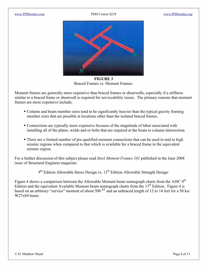
Circular or Infinite Load Path Framing:
Although the framing configuration shown in Figure 3 can be justified from a analytical stand point, the approach shown for framing around an opening would be difficult to construct. As a result this type of circular framing is not recommended and should be avoided. For a further discussion of this subject please read Infinite Load Path? published in the October 2007 issue of STRUCTURE magazine.
www.PDHcenter.com PDH Course S218 www.PDHonline.org
© D. Matthew Stuart Page 4 of 11
FIGURE 3
Braced Frames vs. Moment Frames: Moment frames are generally more expensive than braced frames or shearwalls, especially if a stiffness similar to a braced frame or shearwall is required for serviceability issues. The primary reasons that moment frames are more expensive include;
Column and beam member sizes tend to be significantly heavier than the typical gravity framing member sizes that are possible at locations other than the isolated braced frames.
Connections are typically more expensive because of the magnitude of labor associated with installing all of the plates, welds and or bolts that are required at the beam to column intersection.
There are a limited number of pre-qualified moment connections that can be used in mid to high seismic regions when compared to that which is available for a braced frame in the equivalent seismic region.
For a further discussion of this subject please read Steel Moment Frames 101 published in the June 2008 issue of Structural Engineer magazine.
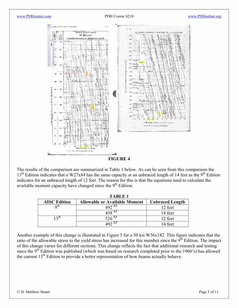
9th Edition Allowable Stress Design vs. 13th Edition Allowable Strength Design: Figure 4 shows a comparison between the Allowable Moment beam nomograph charts from the AISC 9th
Edition and the equivalent Available Moment beam nomograph charts from the 13th Edition. Figure 4 is based on an arbitrary “service” moment of about 500 KF and an unbraced length of 12 to 14 feet for a 50 ksi W27x84 beam.
www.PDHcenter.com PDH Course S218 www.PDHonline.org
© D. Matthew Stuart Page 5 of 11
FIGURE 4
The results of the comparison are summarized in Table 1 below. As can be seen from this comparison the 13th Edition indicates that a W27x84 has the same capacity at an unbraced length of 14 feet as the 9th Edition indicates for an unbraced length of 12 feet. The reason for this is that the equations used to calculate the available moment capacity have changed since the 9th Edition.
TABLE 1
AISC Edition Allowable or Available Moment Unbraced Length 492 KF 12 feet 9th 458 KF 14 feet 526 KF 12 feet 13th 492 KF 14 feet
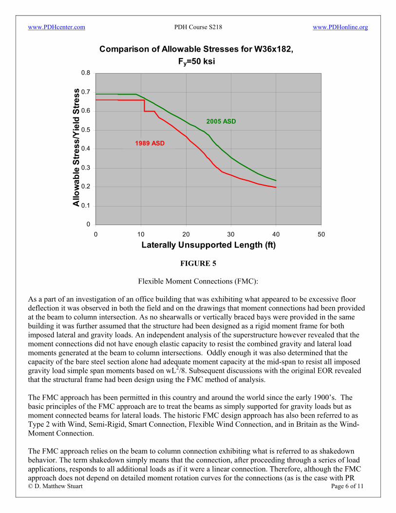
Another example of this change is illustrated in Figure 5 for a 50 ksi W36x182. This figure indicates that the ratio of the allowable stress to the yield stress has increased for this member since the 9th Edition. The impact of this change varies for different sections. This change reflects the fact that additional research and testing since the 9th Edition was published (which was based on research completed prior to the 1960’s) has allowed the current 13th Edition to provide a better representation of how beams actually behave.
www.PDHcenter.com PDH Course S218 www.PDHonline.org
© D. Matthew Stuart Page 6 of 11
Comparison of Allowable Stresses for W36x182, Fy=50 ksi
0
0.1
0.2
0.3
0.4
0.5
0.6
0.7
0.8
0 10 20 30 40 50
Laterally Unsupported Length (ft)
Allo
wab
le S
tress
/Yie
ld S
tress
1989 ASD
2005 ASD
FIGURE 5
Flexible Moment Connections (FMC): As a part of an investigation of an office building that was exhibiting what appeared to be excessive floor deflection it was observed in both the field and on the drawings that moment connections had been provided at the beam to column intersection. As no shearwalls or vertically braced bays were provided in the same building it was further assumed that the structure had been designed as a rigid moment frame for both imposed lateral and gravity loads. An independent analysis of the superstructure however revealed that the moment connections did not have enough elastic capacity to resist the combined gravity and lateral load moments generated at the beam to column intersections. Oddly enough it was also determined that the capacity of the bare steel section alone had adequate moment capacity at the mid-span to resist all imposed gravity load simple span moments based on wL2/8. Subsequent discussions with the original EOR revealed that the structural frame had been design using the FMC method of analysis. The FMC approach has been permitted in this country and around the world since the early 1900’s. The basic principles of the FMC approach are to treat the beams as simply supported for gravity loads but as moment connected beams for lateral loads. The historic FMC design approach has also been referred to as Type 2 with Wind, Semi-Rigid, Smart Connection, Flexible Wind Connection, and in Britain as the Wind-Moment Connection. The FMC approach relies on the beam to column connection exhibiting what is referred to as shakedown behavior. The term shakedown simply means that the connection, after proceeding through a series of load applications, responds to all additional loads as if it were a linear connection. Therefore, although the FMC approach does not depend on detailed moment rotation curves for the connections (as is the case with PR
www.PDHcenter.com PDH Course S218 www.PDHonline.org
© D. Matthew Stuart Page 7 of 11
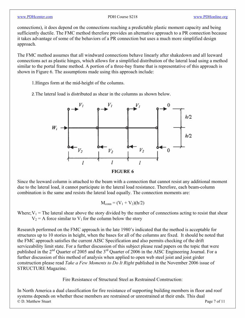
connections), it does depend on the connections reaching a predictable plastic moment capacity and being sufficiently ductile. The FMC method therefore provides an alternative approach to a PR connection because it takes advantage of some of the behaviors of a PR connection but uses a much more simplified design approach. The FMC method assumes that all windward connections behave linearly after shakedown and all leeward connections act as plastic hinges, which allows for a simplified distribution of the lateral load using a method similar to the portal frame method. A portion of a three-bay frame that is representative of this approach is shown in Figure 6. The assumptions made using this approach include:
1.Hinges form at the mid-height of the columns. 2. The lateral load is distributed as shear in the columns as shown below.
FIGURE 6
Since the leeward column is attached to the beam with a connection that cannot resist any additional moment due to the lateral load, it cannot participate in the lateral load resistance. Therefore, each beam-column combination is the same and resists the lateral load equally. The connection moments are:
Mconn = (V1 + V2)(h/2) Where; V1 = The lateral shear above the story divided by the number of connections acting to resist that shear
V2 = A force similar to V1 for the column below the story Research performed on the FMC approach in the late 1980’s indicated that the method is acceptable for structures up to 10 stories in height, when the bases for all of the columns are fixed. It should be noted that the FMC approach satisfies the current AISC Specification and also permits checking of the drift serviceability limit state. For a further discussion of this subject please read papers on the topic that were published in the 2nd Quarter of 2005 and the 3rd Quarter of 2006 in the AISC Engineering Journal. For a further discussion of this method of analysis when applied to open web steel joist and joist girder construction please read Take a Few Moments to Do It Right published in the November 2006 issue of STRUCTURE Magazine.
Fire Resistance of Structural Steel as Restrained Construction: In North America a dual classification for fire resistance of supporting building members in floor and roof systems depends on whether these members are restrained or unrestrained at their ends. This dual
www.PDHcenter.com PDH Course S218 www.PDHonline.org
© D. Matthew Stuart Page 8 of 11
classification is based on the assumption that during a fire (and the resulting exposures to high temperatures) an unrestrained steel beam will not be able to support its own weight or any superimposed dead or live loads when an average temperature of 1,100º Fahrenheit is reached. To obtain a higher restrained rating, the fire test is continued until the entire assembly is judged to no longer support its superimposed load and failure conditions, as indicated by elevated temperatures, are attained in the steel. Tests conducted on steel beam framed roof and floor assemblies indicate that these systems can be considered restrained construction because:
1. The fire endurance of structural steel floor and roof beam is enhanced by the interaction of the beams with the other structural elements and constructions that are integral with or surround the exposed assembly.
2. All steel beam connections to other structural steel members exhibit both axial and rotational
restraint. The least stiff connection typically used for steel framed construction (such as a three-bolt single plate connection) is adequate to develop restrained performance.
Therefore the results of the fire research and computer modeling that have been performed by various agencies, including Underwriters Laboratories, Inc., support the conclusion that a restrained assembly classification and fire protection design is most appropriate for steel beam floor and roof assemblies. For a further discussion of this subject please read a paper on the topic that was published in the 2nd Quarter of 2001 and in the AISC Engineering Journal.
Special Lateral Resisting System Issues:
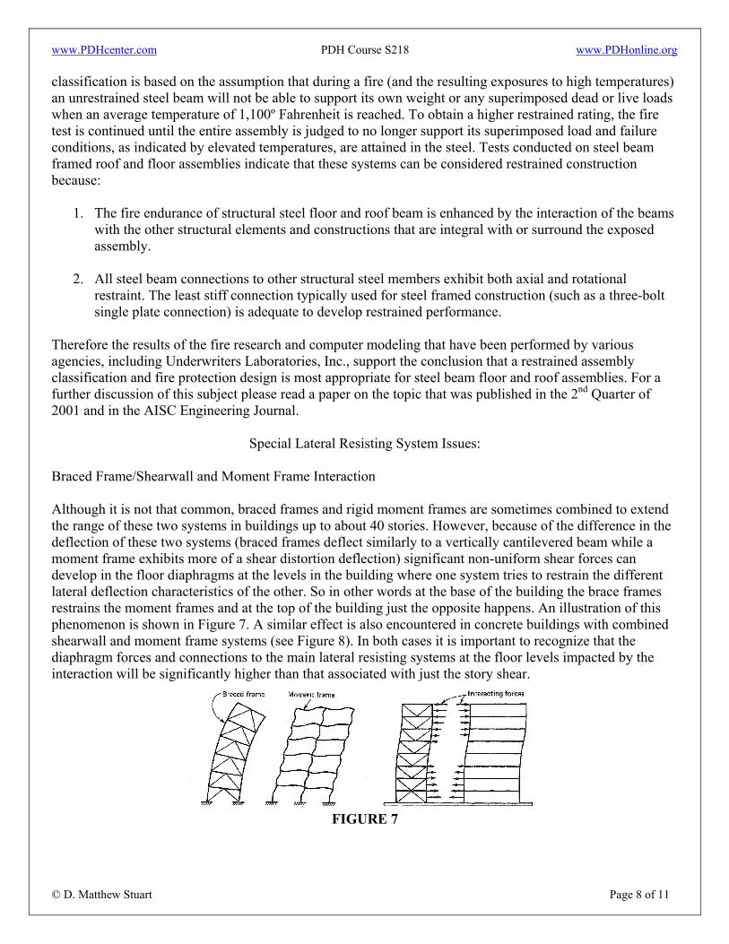
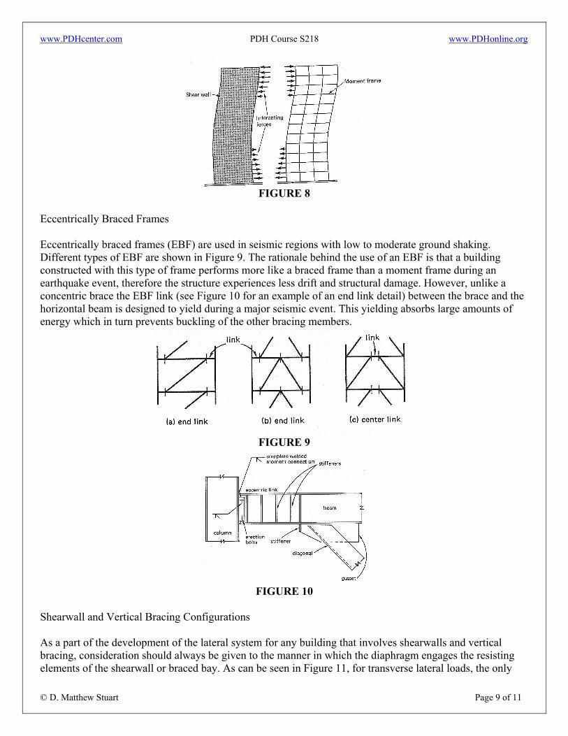
Braced Frame/Shearwall and Moment Frame Interaction Although it is not that common, braced frames and rigid moment frames are sometimes combined to extend the range of these two systems in buildings up to about 40 stories. However, because of the difference in the deflection of these two systems (braced frames deflect similarly to a vertically cantilevered beam while a moment frame exhibits more of a shear distortion deflection) significant non-uniform shear forces can develop in the floor diaphragms at the levels in the building where one system tries to restrain the different lateral deflection characteristics of the other. So in other words at the base of the building the brace frames restrains the moment frames and at the top of the building just the opposite happens. An illustration of this phenomenon is shown in Figure 7. A similar effect is also encountered in concrete buildings with combined shearwall and moment frame systems (see Figure 8). In both cases it is important to recognize that the diaphragm forces and connections to the main lateral resisting systems at the floor levels impacted by the interaction will be significantly higher than that associated with just the story shear.
FIGURE 7
www.PDHcenter.com PDH Course S218 www.PDHonline.org
© D. Matthew Stuart Page 9 of 11
FIGURE 8
Eccentrically Braced Frames Eccentrically braced frames (EBF) are used in seismic regions with low to moderate ground shaking. Different types of EBF are shown in Figure 9. The rationale behind the use of an EBF is that a building constructed with this type of frame performs more like a braced frame than a moment frame during an earthquake event, therefore the structure experiences less drift and structural damage. However, unlike a concentric brace the EBF link (see Figure 10 for an example of an end link detail) between the brace and the horizontal beam is designed to yield during a major seismic event. This yielding absorbs large amounts of energy which in turn prevents buckling of the other bracing members.
FIGURE 9
FIGURE 10
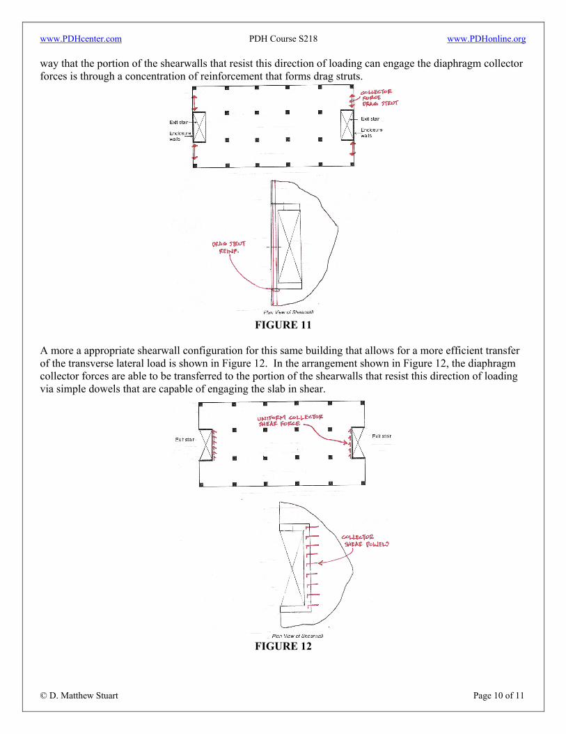
Shearwall and Vertical Bracing Configurations As a part of the development of the lateral system for any building that involves shearwalls and vertical bracing, consideration should always be given to the manner in which the diaphragm engages the resisting elements of the shearwall or braced bay. As can be seen in Figure 11, for transverse lateral loads, the only
www.PDHcenter.com PDH Course S218 www.PDHonline.org
© D. Matthew Stuart Page 10 of 11
way that the portion of the shearwalls that resist this direction of loading can engage the diaphragm collector forces is through a concentration of reinforcement that forms drag struts.
FIGURE 11
A more a appropriate shearwall configuration for this same building that allows for a more efficient transfer of the transverse lateral load is shown in Figure 12. In the arrangement shown in Figure 12, the diaphragm collector forces are able to be transferred to the portion of the shearwalls that resist this direction of loading via simple dowels that are capable of engaging the slab in shear.
FIGURE 12
www.PDHcenter.com PDH Course S218 www.PDHonline.org
© D. Matthew Stuart Page 11 of 11
Miscellaneous:
Additional information concerning the design of low and medium-rise steel buildings can be found in AISC Design Guide 5. In addition a wealth of other resources of information (including Power Point presentations, spreadsheets and other similar mediums) concerning steel design can be found on the AISC website at the following links: http://www.aisc.org/Content/NavigationMenu/Learning_Opportunities/University_Programs/Teaching_Aids1/Teaching_Aids.htm http://www.aisc.org/Template.cfm?Section=Teaching_Aids&template=/ContentManagement/ContentDisplay.cfm&ContentID=25083 A structural design engineer should be prepared to respond to questions posed by bidders after the Contract or Bid Documents are released and to questions posed by the general contractor, fabricator and or erector after the project is awarded. Questions posed during the bid and construction phase are referred to as RFI’s or Requests for Information, or RFC’s (Requests for Clarification). Often the most appropriate response to a RFI is to simply refer the contractor to that portion of the drawings or details that already addresses the question. Other times the questions may have to be answered via the development of a sketch or other similar type of detail that provides further clarification or additional information relative to the area of concern. The worse case scenario, however, is a situation in which the question reveals an inadequacy in the design documents that leads to a moderate to significant change in the Contract Documents. This later case typically leads to a change order request (i.e. an increase in the previously agreed upon project construction cost) from the contractor which in turn can lead to an errors and omissions (E&O) claim against the EOR. In either case the designer should be familiar with the RFI process and approach the development of the Contract Documents so that almost any potential future RFI can be answered by the issued drawings or specifications. A good source of information concerning the RFI process is the AISC Code of Standard Practice. A structural engineer also needs to be familiar with the types of deterioration that can occur with a steel structural. In particular, when joining dissimilar metals in environmental conditions that are conducive to galvanic deterioration, the engineer must be aware of the potential for this type of problem and the methods that can be used to avoid the problem. For a further discussion of this issue please read Dissimilar Metal Corrosion, Course S118. Deterioration of steel can also occur in other forms. For a further discussion of metal deterioration in general please read Metal Deterioration, Course S174. Finally, one other good source of guidance with the design of steel structures is the book entitled Unified Design of Steel Structures by Louis F. Geschwindner (AISC; PSU). The book can be purchased at the following link: http://he-cda.wiley.com/WileyCDA/HigherEdTitle/productCd-0471475580.html