adjustable frequency drive for 3-phase ac motors …€¦ · · 2016-07-18adjustable frequency...
TRANSCRIPT

INSTALLATION AND OPERATING INSTRUCTIONS
MODEL KBAC-24DAdjustable Frequency Drive for 3-Phase AC Motors
NEMA 4X, IP-65KB Part No. 9987 (Black Case) • Part No. 9988 (White Case)
Rated for 208 - 230 Volt 50/60 Hz Induction Motors thru 1 HPOperates from 115 or 208/230 Volt 50/60 Hz Single Phase AC Line Input
Washdown and Watertight for Indoor and Outdoor Use
See Safety Warning on Page 2
The information contained in this manual is intended to be accurate. However, the manufacturer retainsthe right to make changes in design which may not be included herein.
!
TM
A COMPLETE LINE OF MOTOR DRIVES
© 2000 KB Electronics, Inc.
POWER
STATUS
REVERSE
FORWARD
STOP
START
POWER
5040
0
60
70
80
90
100
ON
OFF
30
20
10
NEMA 4X / IP65
AUTO
MANUAL
STOP
AC MOTOR SPEED CONTROLPENTA DRIVE
TM
% SPEED
TM
Pending

TABLE OF CONTENTS
Section Page
i. Simplified Operating Instructions . . . . . . . . . . . . . . . . . . . . . . . . . . . . . . . . . . . . . . . . . . 1
ii. Safety Warning . . . . . . . . . . . . . . . . . . . . . . . . . . . . . . . . . . . . . . . . . . . . . . . . . . . . . . . 2
I. Introduction . . . . . . . . . . . . . . . . . . . . . . . . . . . . . . . . . . . . . . . . . . . . . . . . . . . . . . . . . . 2
II. Wiring Instructions . . . . . . . . . . . . . . . . . . . . . . . . . . . . . . . . . . . . . . . . . . . . . . . . . . . . . 6
III. Setting Selectable Jumpers . . . . . . . . . . . . . . . . . . . . . . . . . . . . . . . . . . . . . . . . . . . . . . 8
IV. Mounting Instructions . . . . . . . . . . . . . . . . . . . . . . . . . . . . . . . . . . . . . . . . . . . . . . . . . . . 9
V. Recommended High Voltage Dielectric Withstand Testing (Hi-Pot) . . . . . . . . . . . . . . . . . 9
VI. Control Operation . . . . . . . . . . . . . . . . . . . . . . . . . . . . . . . . . . . . . . . . . . . . . . . . . . . . . 10
VII. AC Line Fusing . . . . . . . . . . . . . . . . . . . . . . . . . . . . . . . . . . . . . . . . . . . . . . . . . . . . . . . 11
VIII. Trimpot Adjustments . . . . . . . . . . . . . . . . . . . . . . . . . . . . . . . . . . . . . . . . . . . . . . . . . . . 11
IX. Diagnostic LEDs . . . . . . . . . . . . . . . . . . . . . . . . . . . . . . . . . . . . . . . . . . . . . . . . . . . . . 13
X. Optional Accessories . . . . . . . . . . . . . . . . . . . . . . . . . . . . . . . . . . . . . . . . . . . . . . . . . . 13
XI. Limited Warranty . . . . . . . . . . . . . . . . . . . . . . . . . . . . . . . . . . . . . . . . . . . . . . . . . . . . . 14
Tables
1. Electrical Ratings . . . . . . . . . . . . . . . . . . . . . . . . . . . . . . . . . . . . . . . . . . . . . . . . . . . . . . 3
2. General Performance Specifications . . . . . . . . . . . . . . . . . . . . . . . . . . . . . . . . . . . . . . . 6
3. Terminal Block Wiring Information . . . . . . . . . . . . . . . . . . . . . . . . . . . . . . . . . . . . . . . . . 7
4. Fault Recovery and Resetting the Control . . . . . . . . . . . . . . . . . . . . . . . . . . . . . . . . . . . .11
5. Control Mode and Status LED Indication . . . . . . . . . . . . . . . . . . . . . . . . . . . . . . . . . . . 13
Figures
1. Control Layout . . . . . . . . . . . . . . . . . . . . . . . . . . . . . . . . . . . . . . . . . . . . . . . . . . . . . . . . 4
2. Enlarged View of Trimpot Settings . . . . . . . . . . . . . . . . . . . . . . . . . . . . . . . . . . . . . . . . . 4
3. Mechanical Specifications . . . . . . . . . . . . . . . . . . . . . . . . . . . . . . . . . . . . . . . . . . . . . . . 5
4. Power Connections . . . . . . . . . . . . . . . . . . . . . . . . . . . . . . . . . . . . . . . . . . . . . . . . . . . . 7
5. Remote Main Speed Potentiometer Connection . . . . . . . . . . . . . . . . . . . . . . . . . . . . . . . 7
6. Remote Start/Stop Switch Connection . . . . . . . . . . . . . . . . . . . . . . . . . . . . . . . . . . . . . . 7
7. Start/Stop Function Eliminated (Jumper Installed) . . . . . . . . . . . . . . . . . . . . . . . . . . . . . . 7
8. Voltage Following Connection . . . . . . . . . . . . . . . . . . . . . . . . . . . . . . . . . . . . . . . . . . . . 8
9. Enable Circuit Connection . . . . . . . . . . . . . . . . . . . . . . . . . . . . . . . . . . . . . . . . . . . . . . . 8
10. AC Line Input Voltage Selection (J1 and J2) . . . . . . . . . . . . . . . . . . . . . . . . . . . . . . . . . . 8
11. Motor Horsepower Selection (J3) . . . . . . . . . . . . . . . . . . . . . . . . . . . . . . . . . . . . . . . . . . 8
12. Reset Mode Selection (J4) . . . . . . . . . . . . . . . . . . . . . . . . . . . . . . . . . . . . . . . . . . . . . . . 9
13. Motor Frequency Selection (J5) . . . . . . . . . . . . . . . . . . . . . . . . . . . . . . . . . . . . . . . . . . . 9
14. Motor Frequency Multiplier Selection (J6) . . . . . . . . . . . . . . . . . . . . . . . . . . . . . . . . . . . . 9
15. Boost Mode Selection (J7) . . . . . . . . . . . . . . . . . . . . . . . . . . . . . . . . . . . . . . . . . . . . . . . 9
16. Hi-Pot Setup . . . . . . . . . . . . . . . . . . . . . . . . . . . . . . . . . . . . . . . . . . . . . . . . . . . . . . . . 10
17. MAX Trimpot Range . . . . . . . . . . . . . . . . . . . . . . . . . . . . . . . . . . . . . . . . . . . . . . . . . . . 11
18. MIN Trimpot Range . . . . . . . . . . . . . . . . . . . . . . . . . . . . . . . . . . . . . . . . . . . . . . . . . . . 11
19. ACCEL Trimpot Range . . . . . . . . . . . . . . . . . . . . . . . . . . . . . . . . . . . . . . . . . . . . . . . . . 11
20. DECEL Trimpot Range . . . . . . . . . . . . . . . . . . . . . . . . . . . . . . . . . . . . . . . . . . . . . . . . . 12
21. COMP Trimpot Range . . . . . . . . . . . . . . . . . . . . . . . . . . . . . . . . . . . . . . . . . . . . . . . . . 12
22. CL Trimpot Range . . . . . . . . . . . . . . . . . . . . . . . . . . . . . . . . . . . . . . . . . . . . . . . . . . . . 12
23. I2t Trip Time vs Motor Current . . . . . . . . . . . . . . . . . . . . . . . . . . . . . . . . . . . . . . . . . . . . .12
23. BOOST Trimpot Range . . . . . . . . . . . . . . . . . . . . . . . . . . . . . . . . . . . . . . . . . . . . . . . . 13
ii

i. SIMPLIFIED OPERATING INSTRUCTIONS
Application Information – Most totally enclosed fan-cooled (TEFC) and open ventilat-ed 3-phase motors will overheat if used with an inverter beyond a limited speed range atfull torque. Therefore, it is necessary to reduce motor load as speed is decreased.
Note: Some fan-cooled motors can be used over a wider speed range. Consult motormanufacturer for details.
WARNING! There are some motors whose characteristics cause overheating andwinding failure under light load or no load conditions. If the motor is operated in
this manner for an extended period of time, it is recommended that the unloaded motorcurrent be checked from 2-15 Hz (60-450 RPM) to ensure motor current does not exceedthe nameplate rating. Do not use motor if the motor current exceeds the nameplaterating.
Inverter duty and most totally enclosed non-ventilated (TENV) motors can provide fullrated motor torque over an extended speed range without overheating.
It is recommended that this control be used with Inverter Duty or TENVmotors.
If external fan-cooling is provided, open-ventilated motors can also achieve an extendedspeed range at full rated torque. A box fan or blower with a minimum of 100 CFM is rec-ommended. Mount the fan such that the motor is surrounded by the airflow.
WARNING! Disconnect main power when making connections to thecontrol.
A. AC Line Connection – Connect the AC line to L1 and L2 terminals of Terminal BlockTB1 and the ground wire (Earth) to the green ground screw as shown in Figure 4, onpage 7, and as described in Section IIA, on page 7, and Section IIB, on page 7. SetJumpers J1 and J2 to the corresponding AC line input voltage (115 or 208/230 VoltsAC).
B. Motor Connection – Connect the motor to U, V and W terminals of Terminal BlockTB1 as shown in Figure 4, on page 7, and as described in Section IIC, on page 7.Motor cable length should not exceed 100 feet (30m) – special reactors may berequired – contact the Sales Department.
C. Start/Stop Switch – The control is supplied with a prewired Start/Stop Switch asdescribed in Section IIE, on page 7, which is used to start and stop the control. InManual Start Mode, this switch must be used to start the control each time the ACpower is lost or the control shuts down due to a fault.
D. Jumper Settings – All jumpers are factory set for most applications. Be sure JumperJ3 is set to the correct motor HP. See Section IIIB, on page 8.
E. AC Line Fusing – Install a fuse or circuit breaker in the AC line. Fuse each con-ductor that is not at ground potential. See Section VII, on page 11, for recommend-ed fuse size.
F. Trimpot Settings – All trimpots have been factory set as shown in Figure 2, on page4. Trimpots may be readjusted as described in Section VIII, on page 11.
G. Diagnostic LEDs – After power has been applied, observe the LEDs to verify prop-er control operation as described in Section IX, on page 14.
1
IMPORTANT – You must read these simplified operating instructions before pro-ceeding. These instructions are to be used as a reference only and are not intendedto replace the detailed instructions provided herein. You must read the SafetyWarning, on page 2, before proceeding.
!
!
!

I. INTRODUCTIONThank you for purchasing the KBAC-24D. KB Electronics, Inc. is committed to providing totalcustomer satisfaction by producing quality products that are easy to install and operate. TheKBAC-24D is manufactured with surface mount components incorporating advanced circuit-ry and technology.
The KBAC-24D Adjustable Frequency Drive is a variable speed control in a NEMA-4X / IP-65 washdown and watertight enclosure. It is designed to operate 208 - 230 Volt 3-phase ACinduction motors through 3.6 Amps RMS. The sine wave coded Pulse Width Modulated(PWM) output, which operates at a frequency of 16 kHz, provides high motor torque, high effi-ciency and low noise. The control operates from 115 or 208/230 Volt 50/60 Hz single phaseAC line input.
Due to its user friendly design, tailoring the KBAC-24D to specific applications is easilyaccomplished via selectable jumpers and trimpot adjustments. This eliminates the comput-er-like programming required on other drives. However, for most applications no adjustmentsare necessary.
Main features include adjustable RMS Current Limit and I2t Motor Overload Protection. Inaddition, Adjustable Slip Compensation provides excellent load regulation over a wide speedrange. Power Start™ delivers over 200% motor torque to ensure startup of high frictionalloads. Electronic Inrush Current Limit (EICL™) eliminates harmful AC line inrush current andAdjustable Linear Acceleration and Deceleration make the drive suitable for soft-start appli-cations. Additional features include holding torque at zero speed and ride-through which pro-vides a smooth recovery to the previous set speed during a momentary power loss.
2
ii. SAFETY WARNING! Please read carefully
This product should be installed and serviced by a qualified technician, electrician, or elec-trical maintenance person familiar with its operation and the hazards involved. Proper instal-lation, which includes wiring, mounting in proper enclosure, fusing or other overcurrent pro-tection, and grounding can reduce the chance of electrical shocks, fires, or explosion in thisproduct or products used with this product, such as electric motors, switches, coils, solenoids,and/or relays. Eye protection must be worn and insulated adjustment tools must be usedwhen working with control under power. This product is constructed of materials (plastics,metals, carbon, silicon, etc.) which may be a potential hazard. Proper shielding, grounding,and filtering of this product can reduce the emission of radio frequency interference (RFI)which may adversely affect sensitive electronic equipment. If further information is requiredon this product, contact the factory. It is the responsibility of the equipment manufacturer andindividual installer to supply this Safety Warning to the ultimate end user of this product. (SWeffective 11/1992.)
This control contains electronic Start/Stop circuits that can be used to start and stop thecontrol. However these circuits are never to be used as safety disconnects since they are notfail-safe. Use only the AC line for this purpose.
Be sure to follow all instructions carefully. Fire and/or electrocution can result due toimproper use of this product.
!
This product complies with all CE directives pertinent at the time of manufacture.Contact factory for detailed installation and Declaration of Conformity. Installation of
a CE approved RFI filter (KBRF-300 [P/N 9484] or equivalent) is required. Additional shield-ed motor cable and/or AC line cables may be required along with a signal isolator (SIAC [P/N9488] or equivalent).

Standard front panel features include diagnostic LEDs for power on and control status, aStart/Stop Switch and a Main Speed Potentiometer. Other features include a Barrier TerminalBlock to facilitate wiring of the AC line and motor, adjustable trimpots (MAX, MIN, ACCEL,DECEL, COMP, CL, BOOST) and selectable jumpers (line voltage, motor horsepower, autoor manual reset modes, motor frequency, frequency multiplier, fixed or adjustable boost).
Optional accessories include a Forward-Stop-Reverse Switch, Power On/Off Switch, SignalIsolator, Auto/Manual Switch, and Multi Speed Board. Quick-connect terminals are providedfor easy installation of all accessories.
STANDARD FEATURES
• Motor Overload Protection (I2t)* – Provides motor overload protection which prevents motorburnout and eliminates nuisance trips.
• Power Start™ – Provides more than 200% starting torque and ensures startup of high fric-tional loads.
• Electronic Inrush Current Limit (EICL™) – Eliminates harmful inrush AC line current dur-ing startup.
• Dual Voltage Input – The control operates from 115 or 208/230 Volt 50/60 Hz single phaseAC line Input.
• Horsepower Selection – The control contains a horsepower selection jumper which elimi-nates the need to recalibrate the CL trimpot for different motors.
• Short Circuit Protection – Shuts down the control if a short circuit occurs at the motor(phase-to-phase).
• Regeneration Protection – Eliminates tripping due to bus overvoltage caused by rapiddeceleration of high inertial loads.
• Slip Compensation with Boost – Provides excellent load regulation over a wide speedrange.
• Start/Stop Switch – Provides electronic start and stop.
• Ride-Through – Provides smooth recovery to the previous set speed during a momentarypower loss.
• Diagnostic LEDs – Power on (POWER) and control status (STATUS).
• Barrier Terminal Block – Facilitates wiring of motor and AC line.
• Protection Features – Undervoltage and overvoltage protection. MOV input transient pro-tection. Microcontroller self-monitoring and auto reboot. Short circuit protected phase-to-phase at motor.
• Industrial Duty Die-Cast Aluminum Case – Available in black finish (P/N 9987) or whiteFDA approved finish (P/N 9988).
• Holding Torque at Zero Speed – Resists motor shaft rotation when the control is in stopmode.
Note: * UL approved as an electronic overload protector for motors.
3
TABLE 1 – ELECTRICAL RATINGS
1, (0.75)
MaximumHorsepower Rating
HP, (kW)
AC Line Input Voltage±10%, 50/60 Hz
(Single Phase Volts AC)
Maximum ContinuousOutput Load Current(RMS Amps/Phase)
115
MaximumAC Line Input Current
(Amps AC)
16
NominalOutput Voltage
(Volts AC)
0 – 230 3.6
208/230 10 0 – 230 3.6 1, (0.75)

VIOLET
WHITE
ORANGE
(BACK VIEW)MAIN SPEED POTENTIOMETER
(BACK VIEW)START/STOP SWITCH
NOTES:1. REV TERMINAL IS USED
FOR OPTIONALFWD-STOP-REV SWITCH.
2. R/F, B- AND B+ TERMINALSARE USED FOR OPTIONALSIAC SIGNAL ISOLATOR.
RED
BLACK
WHITE
CL BOOSTCOMPACCEL DECELMINMAX
P2 P1P3
STOP
FWD
RUN
REV
COM
STOP
R/F
GBR Y
PO
WE
RS
TA
TU
S
LED BOARD
CON1
J1
115V 230V
L2B
(RED)(WHT)
BC0 BC+ B+
(BLK)
B- BC-
L2AL1BL1A
L2 AC LINEL1WVUMOTOR
TB1
KBAC-24D
1/21/4
3/41HP
ADJ
MULT2X
1X
FREQ50HZ
60HZ
BOOSTFIX
AUTO
MAN
J3
J7
J5
J6
J2
115V
J4
230V
4
FIGURE 1 – CONTROL LAYOUT(Illustrates Factory Setting of Jumpers and Approximate Trimpot Settings)
CL BOOSTCOMPACCEL DECELMINMAX
FIGURE 2 – ENLARGED VIEW OF TRIMPOT SETTINGS
PO
WE
R
STA
TU
S
RE
VE
RS
E
FO
RW
AR
D
STO
P
STA
RT
PO
WE
R
5040 0
60 70 80 90 100
ON
OF
F
30 20 10
NE
MA
4X
/ IP
65
AU
TO
MA
NU
AL
STO
P
AC
MO
TOR
SP
EE
D C
ON
TR
OL
PE
NTA
DR
IVE
TM
% S
PE
ED
FO
RW
AR
D-S
TO
P-R
EV
ER
SE
AN
D P
OW
ER
ON
/OF
F S
WIT
CH
ES
KB
AC
-24D
SH
OW
N W
ITH
OP
TIO
NA
L A
UT
O/M
AN
UA
L,
RE
CO
MM
EN
DE
D M
OU
NT
ING
SC
RE
W:
1/4"
(M
6)
2.53
[139
.97]
5.51
[128
.59]
5.06
[7.9
7]0.
31
5.86
9.53
[224
.00]
8.82
[208
.17]
8.20
[241
.96]
[64.
35]
[148
.94]
TM
5
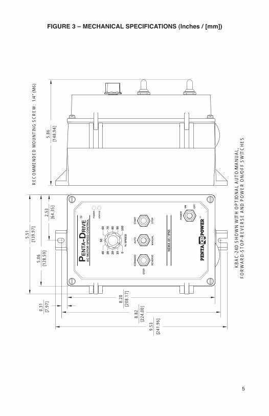
FIGURE 3 – MECHANICAL SPECIFICATIONS (Inches / [mm])

II. WIRING INSTRUCTIONS
WARNING! Read Safety Warning, on page 2, before using this control.Disconnect the AC line before wiring.
Note: To avoid erratic operation, do not bundle AC line and motor wires with wires from sig-nal following, Start/Stop Switch or any other signal wires. Use shielded cables on all signalwiring over 12” (30cm). Shield should be Earth grounded on the control side only. Wire thecontrol in accordance with the National Electrical Code requirements and other codes thatmay apply to your area. See Table 3 and Figure 4, on page 7.
Be sure to properly fuse each AC line conductor that is not at ground potential. Do not fuseneutral or grounded conductors. See Section VII, on page 11. A separate AC line switchor contactor must be wired as a disconnect so that each ungrounded conductor is opened.An accessory Power On/Off Switch (P/N 9482) may be used in lieu of, or in addition to, theStart/Stop Switch. The switch can be wired for single pole or double pole operation, asrequired.
To maintain the watertight integrity of the control, be sure to use suitable watertight connec-tors and wiring which are appropriate for the application. Two 7/8” (22.2mm) knockout holesare provided for standard 1/2” knockout connectors (not supplied) for wiring. A watertightplug is provided if only one knockout is required.
The KBAC-24D is designed with a hinged case so that when the front cover is open, all wiringstays intact. To open the cover, the four screws must be loosened so they are no longerengaged in the case bottom. After mounting and wiring, close the cover making sure that thewires do not get caught or crimped as the cover is closed. Tighten all four cover screws sothat the gasket is slightly compressed. Do not over tighten.
6
!
1.5
Parameter Specification
Output Frequency (Hz)
Minimum Operating Frequency at Motor (Hz)
Factory Setting
AC Line Input Voltage (Volts AC, ±10%, 50/60 Hz) 115 or 208/230 208/230
Maximum Load Capacity (% for 2 Minutes) 150 —
Switching Frequency at Motor (kHz) 16 —
Signal Following (Non-Isolated Input1) Input Voltage (Volts DC) 0 – 5 —
Signal Following Input Resolution (Bits) 8 —
Maximum Speed Trimpot (MAX) Range (% of Frequency Setting) 70 – 110 100
Minimum Speed Trimpot (MIN) Range (% of Frequency Setting) 0 – 40 0
Acceleration Trimpot (ACCEL) Range (Seconds) 0.3 – 20 1.5
—
Deceleration Trimpot (DECEL) Range (Seconds) 0.3 – 20 1.5
Slip Compensation Trimpot (COMP) Range (Volts/Hz/Amp) 0 – 3
Current Limit Trimpot (CL) Range (% Range Setting) 0 – 200 160
Boost Trimpot (BOOST) Range for 50 Hz Output Frequency (Volts AC) 0 – 70 —
Boost Trimpot (BOOST) Range for 60 Hz Output Frequency (Volts AC) 0 – 35 5
Motor Horsepower Selection (HP) 1/4, 1/2, 3/4, 1 1
0 – 50, 0 – 60 0 – 60
1
Speed Regulation (30:1 Speed Range) (% Base Speed)2 2.5 —
Speed Range (Ratio) 60:1 —
Operating Temperature Range (°C) 0 – 45 —
TABLE 2 – GENERAL PERFORMANCE SPECIFICATIONS
Frequency Multiplier (1X, 2X) 1, 2 1
Notes: 1. Requires an isolated signal. If a non-isolated signal voltage is used, install the SIAC Signal Isolator (P/N 9488).2. Dependent on motor performance.

A. AC Line Connection – Wire theAC line input to L1 and L2 terminalsof Terminal Block TB1 as shown inFigure 4. Be sure both Jumpers J1and J2 are set to the “115V” posi-tion for 115 Volt AC line input or tothe “230V” position for 208/230 VoltAC line input.
B. Ground Connection – Earthground the control chassis usingthe green ground screw that is pro-vided on the inside of the control tothe right side of Terminal Block TB1as shown in Figure 4.
C. Motor Connection – Wire themotor leads to U, V and W termi-nals of Terminal Block TB1 asshown in Figure 4. Be sureJumper J3 is set to the correspon-ding motor horsepower rating.
D. Remote Main SpeedPotentiometer Connection –The control is supplied with aprewired Main SpeedPotentiometer mounted on the front cover. Tooperate the control from a remote potentiometer(5kΩ), remove the white, orange, and violetpotentiometer leads from P1, P2 and P3 termi-nals. The leads may be taped and left inside thecontrol.
The potentiometer assembly may be removed if awatertight seal is used to cover the hole in the frontcover. Connect the remote main speed poten-tiometer wires to P1 (low side), P2 (wiper) and P3(high side) terminals as shown in Figure 5.
E. Remote Start/Stop Switch Connections – The control issupplied with a prewired Start/Stop switch, mounted on thefront cover. To operate the control from a remote Start/StopSwitch (type (ON)-OFF-ON, SPDT), remove the white, blackand red wires from RUN, COM and STOP terminals. Theleads may be taped and left in the control. The switchassembly may be removed if a watertight seal is used tocover the hole in the front cover. Connect the remoteStart/Stop Switch wires to RUN (momentary), COM (com-mon) and STOP (constant) terminals as shown in Figure 6.After applying power, momentarily set the Start/Stop Switchto the "START" position. The motor will operate at the set speed of the Main SpeedPotentiometer. To stop the motor, set the Start/Stop Switch to the "STOP" position.
7
12
Supply Wire Gauge (AWG - Cu)
Minimum MaximumDesignation Connection
Maximum Tightening Torque(in-lbs)
AC Line Input
Motor
L1, L2
U, V, W
22 12
22 12 12
TABLE 3 – TERMINAL BLOCK WIRING INFORMATION
TB1
L2 AC LINEL1WVUMOTOR
AC LINEMOTOR (EARTH)GROUND
FIGURE 4 – POWER CONNECTIONS
P2 P1P3
CON1
(BACK VIEW)
ORANGE (WIPER)
WHITE (LOW)
VIOLET (HIGH)
MAIN SPEED POTENTIOMETER
FIGURE 5 – REMOTE MAIN SPEEDPOTENTIOMETER CONNECTION
RED
WHITE
BLACKSTART
STOP
START/STOP SWITCH
RUN
COM
STOP
R/F
FIGURE 6 – REMOTE START/STOPSWITCH CONNECTION
RUN
COM
R/F
STOP
FIGURE 7 – START/STOPFUNCTION ELIMINATED(JUMPER INSTALLED)

Note: To eliminate the Start/Stop function, connect RUN and COM terminals with thejumper that is provided. See Figure 7, on page 7.
CAUTION! Using a jumper to eliminate the Start/Stop function will cause the motor to runat the Main Speed Potentiometer setting when the AC line is applied.
F. Voltage Following Connection – An isolated 0 - 5Volt DC analog signal can also be used to controlmotor speed. See Figure 8.
Note: If an isolated signal voltage is not available,an optional signal isolator can be installed (SIAC,P/N 9488). Connect the isolated signal voltage toP2 (+) and P1 (-) terminals. The MIN trimpot mustbe set fully counterclockwise.
G. Enable Circuit Connection – The control can also bestarted and stopped with an Enable circuit (close tostart). See Figure 9. The Enablefunction is established by wiring aswitch in series with the orangeMain Speed Potentiometer leadwhich connects to P2 terminal.When the Enable switch is closed,the control will accelerate to theMain Speed Potentiometer setting.When the Enable switch is opened,the motor will coast to stop.
III. SETTING SELECTABLE JUMPERSThe KBAC-24D has customer selectable jumpers which must be set before the control canbe used. See Figure 1, on page 4, for location of jumpers.
Note: Disconnect the AC line before changing position of jumpers.
A. AC Line Voltage Selection (J1 and J2) – Jumpers J1 and J2 are both factory set to the“230V” position, for 208/230 Volt AC line input. For 115 Volt AC line input, set bothJumpers J1 and J2 to the “115V” position. See Figure 10.
B. Motor Horsepower Selection (J3) – Jumper J3is factory set to the “1HP” position, for 1HPmotors. For motors of lower horsepower, setJumper J3 to the corresponding position for themotor being used. See Figure 11.
C. Reset Mode Selection (J4) – Jumper J4 is facto-ry set to the "MAN" position, for manual resettingof the control every time the AC line is applied orafter a fault condition has occurred (undervoltage,overvoltage, phase-to-phase short circuit and I2t
8
Control Set for 208/230 Volt AC Line Input(Factory Setting)
Control Set for 115 Volt AC Line Input
J1 Set for 208/230 VoltAC Line Input
J2 Set for 208/230 VoltAC Line Input
J1 Set for 115 VoltAC Line Input
J2 Set for 115 VoltAC Line Input
J1
230V115VJ2
230V
115V
J1
230V115VJ2
230V
115V
FIGURE 10 – AC LINE INPUT VOLTAGE SELECTION
FIGURE 11 – MOTORHORSEPOWER SELECTION
3/4, (0.5)
1/2, (0.37)
J3 Set for 1 HP Motor(Factory Setting)
Motor HorsepowerHP, (kW)
1, (0.75)
1/4, (0.18)
FIGURE 9 – ENABLE CIRCUIT CONNECTION
SWITCH OR RELAY(CLOSE TO START)
ENABLE
P2 P1P3
CON1
(BACK VIEW)
VIOLET (HIGH)
WHITE (LOW)
ORANGE (WIPER)
MAIN SPEED POTENTIOMETER
P1P2P3
CON1
+ -
0 - 5V DC(ISOLATED)
FIGURE 8 – VOLTAGEFOLLOWING CONNECTION
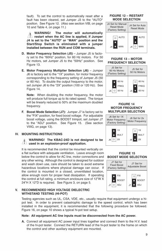
fault). To set the control to automatically reset after afault has been cleared, set Jumper J3 to the "AUTO"position. See Figure 12. (Also see section VIB, on page10 and Table 4, on page 11.)
WARNING! The motor will automaticallyrestart when the AC line is applied, if Jumper
J4 is set to the "AUTO" or “MAN” position and theStart/Stop Switch is eliminated with a jumperinstalled between the RUN and COM terminals.
D. Motor Frequency Selection (J5) – Jumper J5 is facto-ry set to the “60Hz” position, for 60 Hz motors. For 50Hz motors, set Jumper J5 to the “50Hz” position. SeeFigure 13.
E. Motor Frequency Multiplier Selection (J6) – JumperJ6 is factory set to the “1X” position, for motor frequencycorresponding to the frequency setting of Jumper J5 (50or 60 Hz). To double the output frequency to the motor,set Jumper J6 to the “2X” position (100 or 120 Hz). SeeFigure 14.
Note: When doubling the motor frequency, the motorwill produce full torque up to its rated speed. The torquewill be linearly reduced to 50% at the maximum doubledfrequency.
F. Boost Mode Selection (J7): Jumper J7 is factory set tothe "FIX" position, for fixed boost voltage. For adjustableboost voltage, using the BOOST trimpot, set Jumper J7to the "ADJ" position. See Figure 15. (See sectionVIIIG, on page 13).
IV. MOUNTING INSTRUCTIONS
WARNING! The KBAC-24D is not designed to beused in an explosion-proof application.
It is recommended that the control be mounted vertically ona flat surface with adequate ventilation. Leave enough roombelow the control to allow for AC line, motor connections andany other wiring. Although the control is designed for outdoorand wash down use, care should be taken to avoid extremehazardous locations where physical damage can occur. Ifthe control is mounted in a closed, unventilated location,allow enough room for proper heat dissipation. If operatingthe control at full rating, a minimum enclosure size of 12”W X24”H X 12”D is required. See Figure 3, on page 5.
V. RECOMMENDED HIGH VOLTAGE DIELECTRICWITHSTAND TESTING (HI-POT)
Testing agencies such as UL, CSA, VDE, etc., usually require that equipment undergo a hi-pot test. In order to prevent catastrophic damage to the speed control, which has beeninstalled in the equipment, it is recommended that the following procedure be followed.Figure 16, on page 10 shows a typical hi-pot test setup.
Note: All equipment AC line inputs must be disconnected from the AC power.
A. Connect all equipment AC power input lines together and connect them to the H.V. leadof the hi-pot tester. Connect the RETURN lead of the hi-pot tester to the frame on whichthe control and other auxiliary equipment are mounted.
9
!
FIGURE 12 – RESTARTMODE SELECTION
FIGURE 13 – MOTORFREQUENCY SELECTION
J5 Set for60 Hz Motors
(Factory Setting)
J5 Set for50 Hz Motors
J5
60 Hz
50 Hz
FREQ
J5
60 Hz
50 Hz
FREQ
FIGURE 14MOTOR FREQUENCY
MULTIPLIER SELECTION
!
FIGURE 15BOOST MODE SELECTION
J4 Set for AutoReset Mode
J4 Set for ManualReset Mode
(Factory Setting)
J4
AUTO
MAN J4
AUTO
MAN
J6 Set for 1XMotor Frequency(Factory Setting)
J6 Set for 2xMotor Frequency
J6
1X
2X
MULT
J6
1X
2X
MULT
J7 Set forAdjustable Boost
J7 Set forFixed Boost
(Factory Setting)
J7
FIX
ADJ
BOOST
J7
FIX
ADJ
BOOST
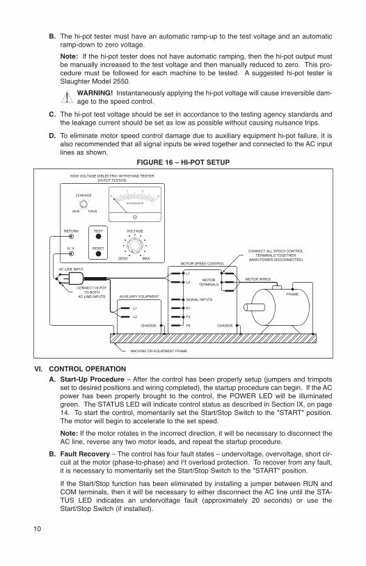
B. The hi-pot tester must have an automatic ramp-up to the test voltage and an automaticramp-down to zero voltage.
Note: If the hi-pot tester does not have automatic ramping, then the hi-pot output mustbe manually increased to the test voltage and then manually reduced to zero. This pro-cedure must be followed for each machine to be tested. A suggested hi-pot tester isSlaughter Model 2550.
WARNING! Instantaneously applying the hi-pot voltage will cause irreversible dam-age to the speed control.
C. The hi-pot test voltage should be set in accordance to the testing agency standards andthe leakage current should be set as low as possible without causing nuisance trips.
D. To eliminate motor speed control damage due to auxiliary equipment hi-pot failure, it isalso recommended that all signal inputs be wired together and connected to the AC inputlines as shown.
VI. CONTROL OPERATION
A. Start-Up Procedure – After the control has been properly setup (jumpers and trimpotsset to desired positions and wiring completed), the startup procedure can begin. If the ACpower has been properly brought to the control, the POWER LED will be illuminatedgreen. The STATUS LED will indicate control status as described in Section IX, on page14. To start the control, momentarily set the Start/Stop Switch to the "START" position.The motor will begin to accelerate to the set speed.
Note: If the motor rotates in the incorrect direction, it will be necessary to disconnect theAC line, reverse any two motor leads, and repeat the startup procedure.
B. Fault Recovery – The control has four fault states – undervoltage, overvoltage, short cir-cuit at the motor (phase-to-phase) and I2t overload protection. To recover from any fault,it is necessary to momentarily set the Start/Stop Switch to the "START" position.
If the Start/Stop function has been eliminated by installing a jumper between RUN andCOM terminals, then it will be necessary to either disconnect the AC line until the STA-TUS LED indicates an undervoltage fault (approximately 20 seconds) or use theStart/Stop Switch (if installed).
10
21
30
AC KILOVOLTS
RETURN
H. V.
(MAIN POWER DISCONNECTED)TERMINALS TOGETHER
CONNECT ALL SPEED CONTROL
HIGH VOLTAGE DIELECTRIC WITHSTAND TESTER
MOTOR SPEED CONTROL
(HI-POT TESTER)
SIGNAL INPUTS
TERMINALS
L1
L2
FRAME
CHASSISCHASSIS
MOTOR MOTOR WIRES
AC LINE INPUTS
RESET
TEST
TO BOTHCONNECT HI-POT
AC LINE INPUT
LEAKAGE
0mA 10mA
MAXZERO
VOLTAGE
AUXILIARY EQUIPMENT
MACHINE OR EQUIPMENT FRAME
L1
L2
P1
P2
P3
FIGURE 16 – HI-POT SETUP
!
WARNING! The motor will automatically start when the AC line is applied or afault is cleared, if Jumper J4 is set to the “AUTO” or “MAN” position and the
Start/Stop Switch is eliminated.
VII. AC LINE FUSINGThis control does not contain AC line fuses. Most electrical codes require that eachungrounded conductor contain circuit protection. It is recommended to install a 20 Amp fuse(Littelfuse 326, Buss ABC or equivalent) or a circuit breaker in series with each ungroundedconductor. Check all electrical codes that apply to the application. Do not fuse motor leads.
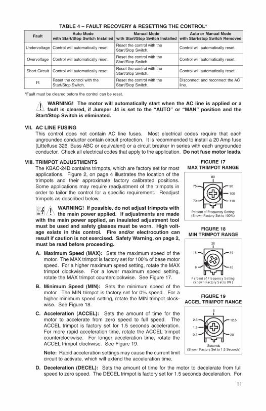
VIII. TRIMPOT ADJUSTMENTSThe KBAC-24D contains trimpots, which are factory set for mostapplications. Figure 2, on page 4 illustrates the location of thetrimpots and their approximate factory calibrated positions.Some applications may require readjustment of the trimpots inorder to tailor the control for a specific requirement. Readjusttrimpots as described below.
WARNING! If possible, do not adjust trimpots withthe main power applied. If adjustments are made
with the main power applied, an insulated adjustment toolmust be used and safety glasses must be worn. High volt-age exists in this control. Fire and/or electrocution canresult if caution is not exercised. Safety Warning, on page 2,must be read before proceeding.
A. Maximum Speed (MAX): Sets the maximum speed of themotor. The MAX trimpot is factory set for 100% of base motorspeed. For a higher maximum speed setting, rotate the MAXtrimpot clockwise. For a lower maximum speed setting,rotate the MAX trimpot counterclockwise. See Figure 17.
B. Minimum Speed (MIN): Sets the minimum speed of themotor. The MIN trimpot is factory set for 0% speed. For ahigher minimum speed setting, rotate the MIN trimpot clock-wise. See Figure 18.
C. Acceleration (ACCEL): Sets the amount of time for themotor to accelerate from zero speed to full speed. TheACCEL trimpot is factory set for 1.5 seconds acceleration.For more rapid acceleration time, rotate the ACCEL trimpotcounterclockwise. For longer acceleration time, rotate theACCEL trimpot clockwise. See Figure 19.
Note: Rapid acceleration settings may cause the current limitcircuit to activate, which will extend the acceleration time.
D. Deceleration (DECEL): Sets the amount of time for the motor to decelerate from fullspeed to zero speed. The DECEL trimpot is factory set for 1.5 seconds deceleration. For
11
!
9075
(Shown Factory Set to 100%)
100
80
Percent of Frequency Setting
70 110
FIGURE 17MAX TRIMPOT RANGE
3515
(Shown Factory Set to 0%)
40
30
0
Percent of Frequency Setting
FIGURE 18MIN TRIMPOT RANGE
Disconnect and reconnect the ACline.
FaultAuto Mode
with Start/Stop Switch InstalledManual Mode
with Start/Stop Switch InstalledAuto or Manual Mode
with Start/stop Switch Removed
Undervoltage
Overvoltage
Short Circuit
I2t
Control will automatically reset.Reset the control with theStart/Stop Switch.
Control will automatically reset.
Control will automatically reset.
Control will automatically reset.
Reset the control with theStart/Stop Switch.
Reset the control with theStart/Stop Switch.
Reset the control with theStart/Stop Switch.
Reset the control with theStart/Stop Switch.
Control will automatically reset.
Control will automatically reset.
TABLE 4 – FAULT RECOVERY & RESETTING THE CONTROL*
*Fault must be cleared before the control can be reset.
!
2.5 12.5
(Shown Factory Set to 1.5 Seconds)
1.5
5
Seconds
0.3 20
FIGURE 19ACCEL TRIMPOT RANGE

more rapid deceleration time, rotate the DECEL trimpot coun-terclockwise. For longer deceleration time, rotate the DECELtrimpot clockwise. See Figure 20.
Note: To provide increased resolution of the ACCEL andDECEL trimpots, 50% rotation covers 0.3 - 5 seconds.
Application Note: On applications with high inertial loads,the deceleration may automatically increase in time. This willslow down the rate of speed decrease to prevent the bus volt-age from rising to the overvoltage trip point. This function iscalled regeneration protection. It is recommended that forvery high inertial loads that both the ACCEL and DECELtrimpots should not be set to less than ten (10) seconds.
E. Slip Compensation (COMP) – Sets the amount ofVolts/Hz/Amp to maintain set motor speed under varyingloads. The COMP trimpot is factory set for 1.5 Volts/Hz/Amp.The slip compensation may be adjusted by the COMP trim-pot as described below. See Figure 21.
1. Wire an ammeter in series with one motor phase.
2. Run the motor and set the unloaded speed to approxi-mately 50%.
3. Load the motor to the rated motor nameplate current(Amps AC).
4. Adjust the COMP trimpot so that the loaded RPM is equalto the unloaded RPM.
5. The motor is now compensated to provide constantspeed under varying loads.
F. Current Limit with I2t Shutdown (CL) – Sets the currentlimit (overload), which limits the maximum current to themotor. The current limit set point is established by the settingof Jumper J3 and the setting of the CL trimpot. See Figure 22.
12
2.30.8
Shown Factory Set to 1.5 Volts/Hz/Amp
1.5
30
Volts/Hz/Amp
FIGURE 21COMP TRIMPOT RANGE
(Shown Factory Set to 160%)Percent of Range Setting
80
40
160
200
120
FIGURE 22CL TRIMPOT RANGE
2.5 12.5
(Shown Factory Set to 1.5 Seconds)
1.5
5
Seconds
0.3 20
FIGURE 20DECEL TRIMPOT RANGE
110 150140130
10
120 160
50
1.0
0.1
SETTING (160%)FACTORY CL
FIGURE 23 – I2t TRIP TIME vs MOTOR CURRENT
NOTES: 1. The CL set point is factory set to 160% of nominal motor current.2. I2t Will not trip below 120% of the CL setting.
MOTOR CURRENT (%)
I2t TRIP TIME(minutes)
The CL trimpot is factory set for 160% of Jumper J3 range setting. For a higher currentlimit setting, rotate the CL trimpot clockwise. For a lower current limit setting, rotate theCL trimpot counterclockwise. The current limit also contains I2t trip function. The controlwill trip according to a predetermined current vs. time function. The trip curve is directlyrelated to the CL set point and can be changed with the CL trimpot. See Figure 23 onpage 12.
CAUTION! Adjusting the CL above 160% of the motor rating can cause overheating ofthe motor. Consult the motor manufacturer. Do not leave the motor in a locked rotor con-dition for more than a few seconds since motor damage may occur.
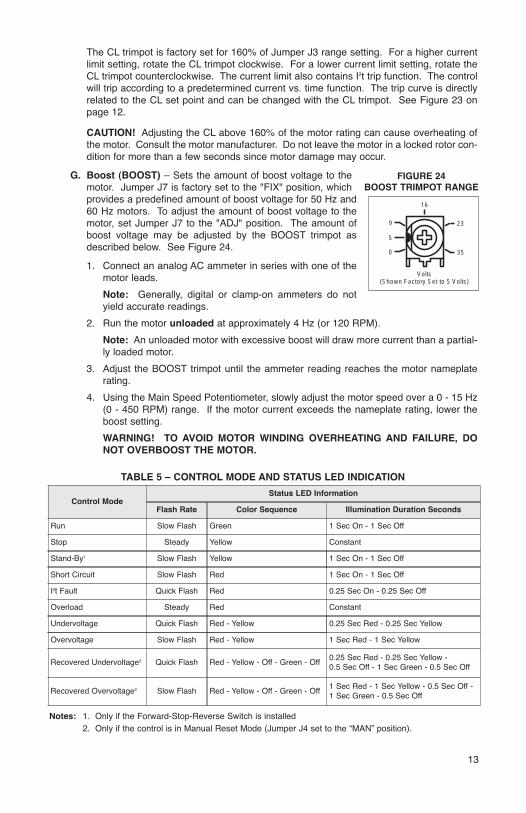
G. Boost (BOOST) – Sets the amount of boost voltage to themotor. Jumper J7 is factory set to the "FIX" position, whichprovides a predefined amount of boost voltage for 50 Hz and60 Hz motors. To adjust the amount of boost voltage to themotor, set Jumper J7 to the "ADJ" position. The amount ofboost voltage may be adjusted by the BOOST trimpot asdescribed below. See Figure 24.
1. Connect an analog AC ammeter in series with one of themotor leads.
Note: Generally, digital or clamp-on ammeters do notyield accurate readings.
2. Run the motor unloaded at approximately 4 Hz (or 120 RPM).
Note: An unloaded motor with excessive boost will draw more current than a partial-ly loaded motor.
3. Adjust the BOOST trimpot until the ammeter reading reaches the motor nameplaterating.
4. Using the Main Speed Potentiometer, slowly adjust the motor speed over a 0 - 15 Hz(0 - 450 RPM) range. If the motor current exceeds the nameplate rating, lower theboost setting.
WARNING! TO AVOID MOTOR WINDING OVERHEATING AND FAILURE, DONOT OVERBOOST THE MOTOR.
13
1 Sec On - 1 Sec Off
1 Sec On - 1 Sec Off
Control Mode
Slow Flash
Status LED Information
Flash Rate Color Sequence Illumination Duration Seconds
Run
Stand-By1
Short Circuit
I2t Fault
Overload
Slow Flash
Slow Flash
Quick Flash
Steady
Undervoltage
Overvoltage
Recovered Undervoltage2
Recovered Overvoltage2 1 Sec Red - 1 Sec Yellow - 0.5 Sec Off -1 Sec Green - 0.5 Sec Off
Quick Flash
Slow Flash
Quick Flash
Slow Flash
Green
Yellow
Red
Red
Red
Red - Yellow
Red - Yellow
Red - Yellow - Off - Green - Off
Red - Yellow - Off - Green - Off
1 Sec On - 1 Sec Off
0.25 Sec On - 0.25 Sec Off
Constant
0.25 Sec Red - 0.25 Sec Yellow
1 Sec Red - 1 Sec Yellow
0.25 Sec Red - 0.25 Sec Yellow - 0.5 Sec Off - 1 Sec Green - 0.5 Sec Off
Notes: 1. Only if the Forward-Stop-Reverse Switch is installed2. Only if the control is in Manual Reset Mode (Jumper J4 set to the “MAN” position).
TABLE 5 – CONTROL MODE AND STATUS LED INDICATION
9 23
(Shown Factory Set to 5 Volts)
5
16
Volts
0 35
FIGURE 24BOOST TRIMPOT RANGE
Stop Steady Yellow Constant

IX. DIAGNOSTIC LEDsThe KBAC-24D is designed with LEDs mounted on the front cover to display the control’soperational status.
A. Power On (ON) – Indicates the presence of bus voltage.
B. Status (STATUS) – The Status LED is a tricolor LED that provides indication of the con-trol’s operational status including installation problems such as incorrect input voltage,overvoltage, undervoltage and control miswiring. It also provides a "normal" indication ifall control and microcontroller operating parameters are proper. See Table 5 on page 13.
X. OPTIONAL ACCESSORIESComplete instructions and connection diagrams are supplied with all accessories to facilitateinstallation.
A. Forward-Stop-Reverse Switch (P/N 9480) – Provides motor reversing and stop func-tions. Mounts on the enclosure cover and is supplied with a switch seal to maintain water-tight integrity.
B. Power On/Off Switch (P/N 9482) – Disconnects the AC line. Mounts on the enclosurecover and is supplied with a switch seal to maintain watertight integrity.
C. Signal Isolator/Run Relay SIAC (P/N 9488): Provides isolation between a non-isolatedsignal voltage source and the KBAC-24D and contains a Run Relay which can be usedto turn on or off equipment or to signal a warning if the control is put into the Stop Modeor a fault has occured.
D. Auto/Manual Switch (P/N 9481) – When used with the SIAC, it either selects an isolat-ed signal from the SIAC or the Main Speed Potentiometer. Mounts on the enclosurecover and is supplied with a switch seal to maintain watertight integrity.
E. Multi Speed Board (P/N 9489) – Provides multi speed operation through a PLC.(Available Spring 2001.)
14

– NOTES –
15

– NOTES –
16

– NOTES –
17

XI. LIMITED WARRANTYFor a period of 18 months from the date of original purchase, KB Electronics, Inc. will repair
or replace, without charge, devices which our examination proves to be defective in material
or workmanship. This warranty is valid if the unit has not been tampered with by unauthorized
persons, misused, abused, or improperly installed and has been used in accordance with the
instructions and/or ratings supplied. The foregoing is in lieu of any other warranty or guaran-
tee, expressed or implied. KB Electronics, Inc. is not responsible for any expense, including
installation and removal, inconvenience, or consequential damage, including injury to any per-
son, caused by items of our manufacture or sale. Some states do not allow certain exclusions
or limitations found in this warranty and therefore they may not apply to you. In any event, the
total liability of KB Electronics, Inc., under any circumstance, shall not exceed the full purchase
price of this product. (rev 2/2000)
(A40289) – Rev. A – 10/2000
KB Electronics, Inc.12095 NW 39th Street, Coral Springs, FL 33065-2516 • (954) 346-4900 • Fax (954) 346-3377Outside Florida Call TOLL FREE (800) 221-6570 • E-mail – [email protected]