administration guide for cisco uc integration for ... · pdf fileadministration guide for...
TRANSCRIPT

Administration Guide for Cisco UC Integration for Microsoft Lync 11.6First Published: 2016-06-23
Americas HeadquartersCisco Systems, Inc.170 West Tasman DriveSan Jose, CA 95134-1706USAhttp://www.cisco.comTel: 408 526-4000 800 553-NETS (6387)Fax: 408 527-0883

THE SPECIFICATIONS AND INFORMATION REGARDING THE PRODUCTS IN THIS MANUAL ARE SUBJECT TO CHANGE WITHOUT NOTICE. ALL STATEMENTS,INFORMATION, AND RECOMMENDATIONS IN THIS MANUAL ARE BELIEVED TO BE ACCURATE BUT ARE PRESENTED WITHOUT WARRANTY OF ANY KIND,EXPRESS OR IMPLIED. USERS MUST TAKE FULL RESPONSIBILITY FOR THEIR APPLICATION OF ANY PRODUCTS.
THE SOFTWARE LICENSE AND LIMITEDWARRANTY FOR THE ACCOMPANYING PRODUCT ARE SET FORTH IN THE INFORMATION PACKET THAT SHIPPED WITHTHE PRODUCT AND ARE INCORPORATED HEREIN BY THIS REFERENCE. IF YOU ARE UNABLE TO LOCATE THE SOFTWARE LICENSE OR LIMITED WARRANTY,CONTACT YOUR CISCO REPRESENTATIVE FOR A COPY.
The Cisco implementation of TCP header compression is an adaptation of a program developed by the University of California, Berkeley (UCB) as part of UCB's public domain versionof the UNIX operating system. All rights reserved. Copyright © 1981, Regents of the University of California.
NOTWITHSTANDINGANYOTHERWARRANTYHEREIN, ALL DOCUMENT FILES AND SOFTWARE OF THESE SUPPLIERS ARE PROVIDED “AS IS"WITH ALL FAULTS.CISCO AND THE ABOVE-NAMED SUPPLIERS DISCLAIM ALL WARRANTIES, EXPRESSED OR IMPLIED, INCLUDING, WITHOUT LIMITATION, THOSE OFMERCHANTABILITY, FITNESS FORA PARTICULAR PURPOSEANDNONINFRINGEMENTORARISING FROMACOURSEOFDEALING, USAGE, OR TRADE PRACTICE.
IN NO EVENT SHALL CISCO OR ITS SUPPLIERS BE LIABLE FOR ANY INDIRECT, SPECIAL, CONSEQUENTIAL, OR INCIDENTAL DAMAGES, INCLUDING, WITHOUTLIMITATION, LOST PROFITS OR LOSS OR DAMAGE TO DATA ARISING OUT OF THE USE OR INABILITY TO USE THIS MANUAL, EVEN IF CISCO OR ITS SUPPLIERSHAVE BEEN ADVISED OF THE POSSIBILITY OF SUCH DAMAGES.
Any Internet Protocol (IP) addresses and phone numbers used in this document are not intended to be actual addresses and phone numbers. Any examples, command display output, networktopology diagrams, and other figures included in the document are shown for illustrative purposes only. Any use of actual IP addresses or phone numbers in illustrative content is unintentionaland coincidental.
Cisco and the Cisco logo are trademarks or registered trademarks of Cisco and/or its affiliates in the U.S. and other countries. To view a list of Cisco trademarks, go to this URL: http://www.cisco.com/go/trademarks. Third-party trademarks mentioned are the property of their respective owners. The use of the word partner does not imply a partnershiprelationship between Cisco and any other company. (1110R)
© 2016 Cisco Systems, Inc. All rights reserved.

C O N T E N T S
P r e f a c e New and Changed Information ix
New and Changed Information ix
C H A P T E R 1 Overview 1
Cisco UC Integration for Microsoft Lync Overview 1
Documentation Resources 2
Community Resources 2
C H A P T E R 2 Deployment Architecture Overview 5
Deployment Architecture 5
C H A P T E R 3 Planning Your Deployment 9
Hardware Requirements 9
Software Requirements 10
Network Requirements 12
Ports and Protocols 12
IPv6_Requirements 14
Supported Codecs 17
Phones, Headsets, and Cameras 17
Expressway for Mobile and Remote Access Deployments 18
Supported Services 19
Cisco AnyConnect 23
Deployment with Single Sign-On 24
Single Sign-On Requirements 25
Single Sign-On and Remote Access 25
Enable SAML SSO in the Client 26
About Service Discovery 26
Administration Guide for Cisco UC Integration for Microsoft Lync 11.6 iii

How the Client Locates Services 27
Cisco UDS SRV Record 28
Survivable Remote Site Telephony 29
Audio and Video Performance Reference 30
Cisco Options Package Files 32
Directory Integration 33
EDI Directory Integration 33
UDS Directory Integration 35
Supported LDAP Directory Services 35
Domain Name System Configuration 36
Quality of Service Configuration 37
Cisco Media Services Interface 37
Set DSCP Values 38
Port Ranges on Cisco Unified Communications Manager 38
Specify a Port Range on the SIP Profile 38
How the Client Uses Port Ranges 38
Options for Setting DSCP Values 39
Set DSCP Values with Group Policy 39
Set DSCP Values on the Network 39
C H A P T E R 4 Setup Certificate Validation 41
Required Certificates 41
Get Certificates Signed by Certificate Authority 42
Certificate Signing Request Forms and Requirements 42
Server Identity in Certificates 43
Import Root Certificates on Client Computers 43
C H A P T E R 5 Server Setup 45
Review the Setup Process 46
Add a Directory to Your Environment 46
Create a Service Profile 47
Create Software Phone Devices 48
Create CSF Devices 48
Video Desktop Sharing 49
Set Up Secure Phone Capabilities 49
Administration Guide for Cisco UC Integration for Microsoft Lync 11.6iv
Contents

Configure the Security Mode 49
Create a Phone Security Profile 49
Configure the Phone Security Profile 50
Configure CSF Devices 51
Specify Certificate Settings 51
Provide Users with Authentication Strings 52
Secure Phone Details 53
Add Directory Number to the Device for Desktop Applications 55
Create Desk Phone Devices 56
Desk Phone Video Configuration 57
Add Directory Number to the Device for Desktop Applications 58
Enable Video Rate Adaptation 59
Enable RTCP on Common Phone Profiles 59
Enable RTCP on Device Configurations 60
Add a CTI Service 60
Apply a CTI Service 61
URI Dialing 62
Associate URIs to Directory Numbers 62
Automatically Populate Directory Numbers with URIs 62
Verify Directory URIs 63
Configure Directory Numbers with URIs 63
Associate the Directory URI Partition 64
Enable FQDN in SIP Requests for Contact Resolution 64
Call Pickup 65
Configure Call Pickup Group 67
Assign Directory Number 67
Other Call Pickup 68
Configure Other Call Pickup 68
Directed Call Pickup 68
Configure Directed Call Pickup 69
Auto Call Pickup 69
Configure Auto Call Pickup 70
Hunt Group 70
Line Group 71
Configure Line Group 71
Administration Guide for Cisco UC Integration for Microsoft Lync 11.6 v
Contents
Hunt List 72
Configure Hunt List 72
Add Line Group to Hunt List 73
Hunt Pilot 73
Configure Hunt Pilot 73
Configure User Associations 74
TFTP Server Address Options 75
Reset Devices 75
Create a CCMCIP Profile 76
C H A P T E R 6 Cisco WebEx Meeting Integration 77
Configure Conferencing for a Cloud-Based Deployment Using Cisco WebEx Meeting
Center 77
Authentication with Cisco WebEx Meeting Center 77
Disable Instant WebEx Meeting Menu Option 77
Specify Conferencing Credentials in the Client 78
C H A P T E R 7 Client Installation 79
Installation Overview 79
Use the Command Line 81
Command Line Arguments 82
LCID for Languages 88
Repackage the MSI 90
Use Custom Installers 90
Create Custom Transform Files 91
Deploy with Group Policy 92
Presence Status 94
On the Phone Presence 94
Appear Offline Presence 95
Cisco Media Services Interface 95
Uninstall Cisco UC Integration for Microsoft Lync 96
C H A P T E R 8 Configuration 99
Global Configuration Files 99
Group Configuration Files 99
Administration Guide for Cisco UC Integration for Microsoft Lync 11.6vi
Contents

Configuration File Requirements 101
C H A P T E R 9 Deployment Configuration 103
Create Group Configurations 103
Create Global Configurations 105
Restart Your TFTP Server 105
Configuration File Structure 106
Client Parameters 107
Directory Attribute Mapping Parameters 111
Directory Connection Parameters 112
Directory Query Parameters 114
Contact Photo Retrieval 119
Contact Photo Parameters 120
Contact Resolution 122
Phone Parameters 123
Policy Parameters 125
Voicemail Parameters 129
Internet Explorer Pop-up Parameters 130
Configure Automatic Updates 132
Configure Problem Reporting 133
PRT Options 134
Decrypt the Problem Report 134
Custom Embedded Tabs 135
Custom Embedded Tab Definitions 135
User Custom Tabs 137
Custom Icons 137
UserID Tokens 137
JavaScript Notifications 137
Show Call Events in Custom Tabs 138
Custom Embedded Tab Example 139
Configuration File Example 140
Registry Key Configuration 140
C H A P T E R 1 0 Troubleshoot Cisco UC Integration for Microsoft Lync 141
Configuration Issues 141
Administration Guide for Cisco UC Integration for Microsoft Lync 11.6 vii
Contents

Directory Integration Issues 143
ADSI Error Codes 144
Audio, Video, and Device Issues 144
Administration Guide for Cisco UC Integration for Microsoft Lync 11.6viii
Contents
New and Changed Information
• New and Changed Information, page ix
New and Changed InformationWhere DocumentedDateDescription of Change
See the Planning Your Deploymentchapter for more information.
June 2016Supported software, hardware, and networkrequirements.
• Skype for Business 64-bit support
• Click-to-Call for 64-bit versions of MicrosoftOffice
• Microsoft Office 2016 support
•Windows 10
• Intel Atom Support
• Desk Phone Video Extended to Windows 10
• IPv6
See the Deployment Configurationchapter for more information.
June 2016Security Features:
• Encryption and Decryption of PRTs
• PRT Logging Level
• Invalid Certificate Behavior
• Customer Signature
Administration Guide for Cisco UC Integration for Microsoft Lync 11.6 ix
Where DocumentedDateDescription of Change
See the Deployment Configurationchapter for more information.
June 2016Voice and Video Features:
• High DPI
• Appear Offline presence support
• Survivable Remote Site Telephony
• Opus Codec support
• Far End Camera Control
• DTMF Digit Management
• Click-to-Call Keyboard Shortcut
• Audio and Video Bridge Conferencing
• Sign Out on Inactivity Timer
• Protocol Rate Limiting
See the JawsSounds parameter inthe Deployment Configurationchapter.
June 2016Accessibility Features:
• Default Windows notification sound playedon contact search result.
Administration Guide for Cisco UC Integration for Microsoft Lync 11.6x
New and Changed InformationNew and Changed Information
C H A P T E R 1Overview
• Cisco UC Integration for Microsoft Lync Overview, page 1
• Documentation Resources, page 2
• Community Resources, page 2
Cisco UC Integration for Microsoft Lync OverviewCisco UC Integration for Microsoft Lync is a Microsoft Windows desktop application that provides accessto Cisco Unified Communications from Microsoft Lync and Skype for Business. The solution extends thepresence and instant messaging capabilities of Microsoft Lync and Skype for Business by providing accessto a broad set of Cisco Unified Communications capabilities; including software phone standards-based video,unified messaging, conferencing, desktop phone control and phone presence.
Key features of Cisco UC Integration for Microsoft Lync include:
• Make and receive video calls using the Cisco Precision Video engine.
• Make and receive phone calls through Cisco Unified Communications Manager.
• Drag and drop and right-click integration with the Microsoft Lync contact list.
• Instant Messaging and Presence integration with Microsoft Lync.
• Mute, hold, and transfer during calls.
• Software phone or desktop phone mode selection.
• Communications history of missed, placed, and received calls.
• Audio and visual notification of incoming calls.
• Ad hoc conferencing.
• Visual voicemail.
• Click to Call from Internet Explorer, Microsoft Outlook and other Microsoft Office applications.
• Start a Cisco WebEx meeting from the contact list, a conversation, or a Microsoft Lync and Skype forBusiness instant messaging session.
• Expressway Mobile and Remote Access.
Administration Guide for Cisco UC Integration for Microsoft Lync 11.6 1
• Service Discovery
Documentation ResourcesAbout This Document
The guide provides information to help you complete the following tasks:
• Plan a successful deployment.
• Set up your deployment environment.
• Configure and deploy the application.
• Review supported environments and software.
• Review audio, video, and network requirements.
Additional Documentation
See the Cisco UC Integration for Microsoft Lync documentation and support site for additional resources.This site can be accessed at: http://www.cisco.com/c/en/us/support/unified-communications/uc-integration-tm-microsoft-lync/tsd-products-support-series-home.html. Documentation and resources forthe Cisco Virtualization ExperienceMedia Engine can be accessed at: http://www.cisco.com/en/US/products/ps12862/tsd_products_support_series_home.html.
Community ResourcesCisco provides different community resources where you can engage with support representatives or joinother community members in product discussions.
Cisco product conversation and sharing site
Join other community members in discussing features, functions, licensing, integration, architecture,challenges, and more. Share useful product resources and best practices.https://communities.cisco.com/community/technology/collaboration/product
Cisco support community
Visit the Cisco support community for IT installation, implementation, and administrative questions.https://supportforums.cisco.com/community/netpro/collaboration-voice-video
Cisco support and downloads
Find a wealth of product support resources, download application software, and find bugs based onproduct and version.http://www.cisco.com/cisco/web/support/index.html
Administration Guide for Cisco UC Integration for Microsoft Lync 11.62
OverviewDocumentation Resources

Cisco expert corner
Engage, collaborate, create, and share with Cisco experts. The Cisco expert corner is a collection ofresources that various experts contribute to the community, including videos, blogs, documents, andwebcasts.https://supportforums.cisco.com/community/netpro/expert-corner#view=ask-the-experts
Administration Guide for Cisco UC Integration for Microsoft Lync 11.6 3
OverviewCommunity Resources

Administration Guide for Cisco UC Integration for Microsoft Lync 11.64
OverviewCommunity Resources

C H A P T E R 2Deployment Architecture Overview
• Deployment Architecture, page 5
Deployment ArchitectureDeployment Diagram
The following diagram illustrates the architecture of a typical Cisco UC Integration for Microsoft Lyncdeployment.
Administration Guide for Cisco UC Integration for Microsoft Lync 11.6 5

Deployment Components
The following list describes the components of a typical deployment:
Desk phone
Connects to Cisco Unified Communications Manager for signaling and configuration.
Cisco Unity Connection
Provides voicemail capabilities.
Cisco Unified Communications Manager
• Provides audio and video call management capabilities.
• Provides user and device configuration settings.
• Connects to the directory for user synchronization and user authentication.
Administration Guide for Cisco UC Integration for Microsoft Lync 11.66
Deployment Architecture OverviewDeployment Architecture

Directory
One of the following types of directory:
• Active Directory Domain Services for Windows Server 2012 R2
• Active Directory Domain Services for Windows Server 2008 R2
• OpenLDAP
• Any server that supports LDAPv3 protocol
Administration Guide for Cisco UC Integration for Microsoft Lync 11.6 7
Deployment Architecture OverviewDeployment Architecture

Administration Guide for Cisco UC Integration for Microsoft Lync 11.68
Deployment Architecture OverviewDeployment Architecture

C H A P T E R 3Planning Your Deployment
• Hardware Requirements, page 9
• Software Requirements, page 10
• Network Requirements, page 12
• Supported Codecs, page 17
• Phones, Headsets, and Cameras, page 17
• Expressway for Mobile and Remote Access Deployments, page 18
• Cisco AnyConnect, page 23
• Deployment with Single Sign-On, page 24
• About Service Discovery, page 26
• Audio and Video Performance Reference, page 30
• Cisco Options Package Files, page 32
• Directory Integration, page 33
• Quality of Service Configuration, page 37
Hardware RequirementsInstalled RAM
2GB RAM
Free physical memory
128 MB
Free disk space
256 MB
Administration Guide for Cisco UC Integration for Microsoft Lync 11.6 9

CPU speed and type
Intel AtomMobile AMD Sempron Processor 3600+ 2 GHzIntel Core2 CPU T7400 @ 2. 16 GHz
GPU
Directx 11 on Microsoft Windows 7
I/O ports
USB 2.0 for USB camera and audio devices.
Software RequirementsSupported Versions of Microsoft Lync and Microsoft Skype for Business
• Microsoft Skype for Business 2016
• Microsoft Skype for Business 2015
• Microsoft Lync 2013
Microsoft Lync 2013 is supported with the following caveats:
◦Escalation from a Microsoft Lync group chat session to a voice or video call is not supported.
◦Microsoft Lync 2013 update KB2812461 must be installed to enable right-click to call support.
• Microsoft Lync 2010
Supported Operating Systems
• Microsoft Windows 10, 32 and 64 bit
• Microsoft Windows 8.x, 32 and 64 bit
• Microsoft Windows 7 SP1 or later, 32 and 64 bit
Supported Servers
• Cisco Unified Communications Manager version 9.x or later
• Cisco Unity Connection version 8.6(2) or later
• Cisco WebEx Meetings Server version 2.6 MR1 or later
• Cisco Expressway Series for Cisco Unified Communications Manager 9.x or later
• Cisco TelePresence Video Communications Server 8.1.1 or later
Administration Guide for Cisco UC Integration for Microsoft Lync 11.610
Planning Your DeploymentSoftware Requirements
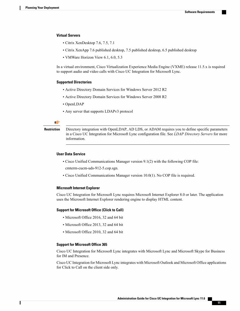
Virtual Servers
• Citrix XenDesktop 7.6, 7.5, 7.1
• Citrix XenApp 7.6 published desktop, 7.5 published desktop, 6.5 published desktop
• VMWare Horizon View 6.1, 6.0, 5.3
In a virtual environment, Cisco Virtualization Experience Media Engine (VXME) release 11.5.x is requiredto support audio and video calls with Cisco UC Integration for Microsoft Lync.
Supported Directories
• Active Directory Domain Services for Windows Server 2012 R2
• Active Directory Domain Services for Windows Server 2008 R2
• OpenLDAP
• Any server that supports LDAPv3 protocol
Directory integration with OpenLDAP, AD LDS, or ADAM requires you to define specific parametersin a Cisco UC Integration for Microsoft Lync configuration file. See LDAP Directory Servers for moreinformation.
Restriction
User Data Service
• Cisco Unified Communications Manager version 9.1(2) with the following COP file:
cmterm-cucm-uds-912-5.cop.sgn.
• Cisco Unified Communications Manager version 10.0(1). No COP file is required.
Microsoft Internet Explorer
Cisco UC Integration for Microsoft Lync requires Microsoft Internet Explorer 8.0 or later. The applicationuses the Microsoft Internet Explorer rendering engine to display HTML content.
Support for Microsoft Office (Click to Call)
• Microsoft Office 2016, 32 and 64 bit
• Microsoft Office 2013, 32 and 64 bit
• Microsoft Office 2010, 32 and 64 bit
Support for Microsoft Office 365
Cisco UC Integration for Microsoft Lync integrates with Microsoft Lync and Microsoft Skype for Businessfor IM and Presence.
Cisco UC Integration forMicrosoft Lync integrates withMicrosoft Outlook andMicrosoft Office applicationsfor Click to Call on the client side only.
Administration Guide for Cisco UC Integration for Microsoft Lync 11.6 11
Planning Your DeploymentSoftware Requirements

Cisco UC Integration with Microsoft Lync is therefore compatible with all versions of Microsoft Lync, Skypefor Business, Outlook, and Office applications whether they are Office 365-based or traditional on-premisedeployments.
Network RequirementsICMP requests
Cisco UC Integration for Microsoft Lync sends Internet Control Message Protocol (ICMP) requests to theTFTP server. These requests enable the client to determine if it can connect to Cisco Unified CommunicationsManager. You must configure firewall settings to allow ICMP requests from the client. If your firewall doesnot allow ICMP requests, the application cannot establish a connection to Cisco Unified CommunicationsManager.
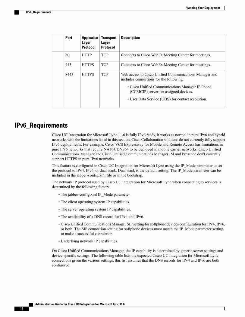
Ports and ProtocolsThe client uses the ports and protocols listed in the following table. If you plan to deploy a firewall betweenthe client and a server, configure the firewall to allow these ports and protocols.
DescriptionTransportLayerProtocol
ApplicationLayerProtocol
Port
Configuration
Connect to the TFTP server to download client configurationfiles.
TCPHTTP6970
Connects to the TFTP server to download client configurationfiles securely for Cisco Unified CommunicationsManager release11.0 and later.
TCPHTTPS6972
Hostname resolution.UDPDNS53
Issues Locally Significant Certificates (LSC) to IP phones. Thisport is the listening port for Cisco Unified CommunicationsManager CertificateAuthority Proxy Function (CAPF) enrollment.
TCPCAPF3804
Traffic to Cisco Unified Communications Manager and CiscoUnified Communications Manager IM and Presence Service.
HTTPS8443
Connects to local port to provide Simple Object Access Protocol(SOAP) web services.
TCPSOAP8191
Directory Integration—For LDAP contact resolution one of the following ports are used based on LDAPconfiguration.
Administration Guide for Cisco UC Integration for Microsoft Lync 11.612
Planning Your DeploymentNetwork Requirements

DescriptionTransportLayerProtocol
ApplicationLayerProtocol
Port
LDAP TCP (UDP) Connects to an LDAP directory service.TCPLDAP389
Connects to a Global Catalog server for contact searches.TCPLDAP3268
LDAPS TCP Connects securely to an LDAP directory service.TCPLDAPS636
LDAPS TCP Connects securely to the Global Catalog server.TCPLDAPS3269
Communication Manager Signaling
Computer Telephony Interface (CTI) used for desk phone control.TCPCTI2748
Provides Session Initiation Protocol (SIP) call signaling.TCPSIP5060
SIP over TCP Provides secure SIP call signaling. (Used if SecureSIP is enabled for device.)
TCPSIP overTLS
5061
Far end camera control (FECC).TCPFECC30000 to39999
Binary Floor Control Protocol (BFCP) for video screen sharingcapabilities.
UDPBFCP5070 to6070
Voice or Video Media Exchange
Sends RTP media streams for audio or video.UDPRTP16384 to32766
Unity Connection
Used for Cisco Unity Connection to receive notifications of voicemessages (new message, message update, and message deleted).
TCPHTTP7080
Used for Cisco Unity Connection to securely receive notificationsof voice messages (new message, message update, and messagedeleted).
TCPHTTPS7443
Connects to Cisco Unity Connection for voicemail.TCPHTTPS443
Cisco WebEx Meetings
Administration Guide for Cisco UC Integration for Microsoft Lync 11.6 13
Planning Your DeploymentPorts and Protocols
DescriptionTransportLayerProtocol
ApplicationLayerProtocol
Port
Connects to Cisco WebEx Meeting Center for meetings.TCPHTTP80
Connects to Cisco WebEx Meeting Center for meetings.TCPHTTPS443
Web access to Cisco Unified Communications Manager andincludes connections for the following:
• Cisco Unified Communications Manager IP Phone(CCMCIP) server for assigned devices.
• User Data Service (UDS) for contact resolution.
TCPHTTPS8443
IPv6_RequirementsCisco UC Integration for Microsoft Lync 11.6 is fully IPv6 ready, it works as normal in pure IPv6 and hybridnetworks with the limitations listed in this section. Cisco Collaboration solutions do not currently fully supportIPv6 deployments. For example, Cisco VCS Expressway for Mobile and Remote Access has limitations inpure IPv6 networks that require NAT64/DNS64 to be deployed in mobile carrier networks. Cisco UnifiedCommunications Manager and Cisco Unified Communications Manager IM and Presence don't currentlysupport HTTPS in pure IPv6 networks.
This feature is configured in Cisco UC Integration for Microsoft Lync using the IP_Mode parameter to setthe protocol to IPv4, IPv6, or dual stack. Dual stack is the default setting. The IP_Mode parameter can beincluded in the jabber-config.xml file or in the bootstrap.
The network IP protocol used by Cisco UC Integration for Microsoft Lync when connecting to services isdetermined by the following factors:
• The jabber-config.xml IP_Mode parameter.
• The client operating system IP capabilities.
• The server operating system IP capabilities.
• The availability of a DNS record for IPv4 and IPv6.
• Cisco Unified CommunicationsManager SIP setting for softphone devices configuration for IPv4, IPv6,or both. The SIP connection setting for softphone devices must match the IP_Mode parameter settingto make a successful connection.
• Underlying network IP capabilities.
On Cisco Unified Communications Manager, the IP capability is determined by generic server settings anddevice-specific settings. The following table lists the expected Cisco UC Integration for Microsoft Lyncconnections given the various settings, this list assumes that the DNS records for IPv4 and IPv6 are bothconfigured.
Administration Guide for Cisco UC Integration for Microsoft Lync 11.614
Planning Your DeploymentIPv6_Requirements

When the Client OS, Server OS, and IP_Mode parameter are set to Dual_Stack, Cisco UC Integration forMicrosoft Lync will use either IPv4 or IPv6 address for connections with the server in accordance withRFC6555.
Connection OutcomeIP_Mode parameterServer OSClient OS
IPv4 ConnectionIPv4_OnlyIPv4 OnlyIPv4 Only
Connection FailureIPv6_Only
IPv4 ConnectionDual_Stack
Connection FailureIPv4_OnlyIPv6 OnlyIPv4 Only
Connection FailureIPv6_Only
Connection FailureDual_Stack
Connection FailureIPv4_OnlyIPv4 OnlyIPv6 Only
Connection FailureIPv6_Only
Connection FailureDual_Stack
Connection FailureIPv4_OnlyIPv6 OnlyIPv6 Only
IPv6 ConnectionIPv6_Only
IPv6 ConnectionDual_Stack
IPv4 ConnectionIPv4_OnlyDual StackIPv4 Only
Connection FailureIPv6_Only
IPv4 ConnectionDual_Stack
Connection FailureIPv4_OnlyDual StackIPv6 Only
IPv6 ConnectionIPv6_Only
IPv6 ConnectionDual_Stack
IPv4 ConnectionIPv4_OnlyIPv4 OnlyDual Stack
Connection FailureIPv6_Only
IPv4 ConnectionDual_Stack
Administration Guide for Cisco UC Integration for Microsoft Lync 11.6 15
Planning Your DeploymentIPv6_Requirements

Connection OutcomeIP_Mode parameterServer OSClient OS
Connection FailureIPv4_OnlyIPv6 OnlyDual Stack
IPv6 ConnectionIPv6_Only
IPv6 ConnectionDual_Stack
IPv4 ConnectionIPv4_OnlyDual StackDual Stack
IPv6 ConnectionIPv6_Only
IPv6 ConnectionDual_Stack
When you use Cisco UC Integration for Microsoft Lync in IPv6_only mode, NAT64/DNS64 is required toconnect to an IPv4 infrastructure. For example, when connecting to Cisco WebEx Messenger service, CiscoVCS Expressway for Mobile and Remote Access, and Cisco Spark.
Limitations
• HTTPS Connectivity
◦In an On-Premises deployment, Cisco UC Integration for Microsoft Lync supports IPv4 only andDual stack modes to connect to Cisco Unified Communications Manager and Cisco UnifiedCommunications Manager IM and Presence Service. These servers do not currently support IPv6HTTPS connections.
Cisco UC Integration for Microsoft Lync can connect using HTTPS to Cisco Unity Connectionfor Voicemail using IPv6 only mode.
• Cisco WebEx Messenger Limitations
◦Cisco WebEx Messenger is not supported on IPv6.
• Telephony Limitations
◦When you upgrade user devices on Cisco Unified Communications Manager to either dual stackor IPv6 only, the corresponding client must be upgraded to 11.6.
◦When an installation includes IPv4 endpoints and IPv6 endpoints, we recommend that you use ahardwareMTP to bridge the Audio and Video between these devices. This is supported on hardwareMTPwith Cisco IOS version 15.5. For example, a Cisco 3945 router must run the following T-trainbuild: c3900e-universalk9-mz.SPA.155-2.T2.bin.
◦At present we do not have a solution roadmap to support IPv4 and IPv6 simultaneously in Ciscoendpoints including Cisco UC Integration for Microsoft Lync. Cisco Unified CommunicationsManager supports the current functionality which is IPv4-Only and IPv6-Only. AnMTP is requiredto support calls between IPv4-only and IPv6-only endpoints, or IPv4-only or IPv6-only Gateways.
• Mobile and Remote Access Limitations
◦Cisco VCS Expressway for Mobile and Remote Access doesn't support IPv6.
Administration Guide for Cisco UC Integration for Microsoft Lync 11.616
Planning Your DeploymentIPv6_Requirements

◦If Cisco Unified Communications Manager is configured for an IPv6 SIP connection, you can'tconnect to Cisco Unified Communications Manager using Cisco VCS Expressway for Mobile andRemote Access to use telephony services.
Supported CodecsCodec TypeCodecType
A-lawG.711Audio
µ-law/Mu-law
24 kb/s and 32 kb/sG.722.1
G.729a
Opus
Requires Cisco UnifiedCommunications Manager 11.0 orlater.
H.264/AVCVideo
Phones, Headsets, and CamerasCTI Supported Devices
Cisco UC Integration for Microsoft Lync supports the same CTI devices as Cisco Unified CommunicationsManager version 9.x or later. See the CTI supported device matrix table in the CTI Supported Devices topicof the Cisco Unified TAPI Developer guide for your Cisco Unified Communications Manager version at thefollowing URL:
http://www.cisco.com/c/en/us/support/unified-communications/unified-communications-manager-callmanager/products-programming-reference-guides-list.html
Headsets and Speakers
Plantronics Voyager Pro UC B230Plantronics Blackwire C310
Plantronics Voyager Pro UC BT300Plantronics Blackwire C320
Plantronics Voyager Pro UC WG200/BPlantronics Blackwire C420
Plantronics W740Plantronics Blackwire C435
Administration Guide for Cisco UC Integration for Microsoft Lync 11.6 17
Planning Your DeploymentSupported Codecs
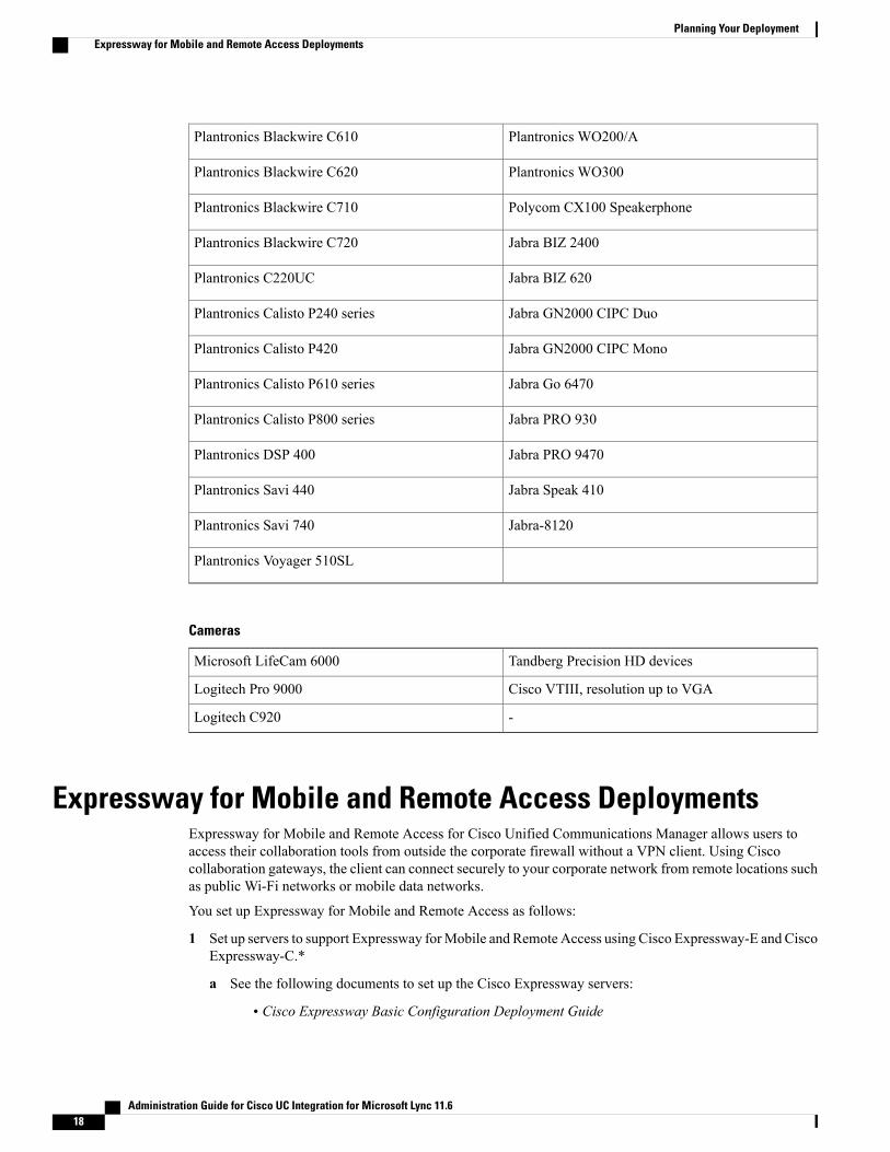
Plantronics WO200/APlantronics Blackwire C610
Plantronics WO300Plantronics Blackwire C620
Polycom CX100 SpeakerphonePlantronics Blackwire C710
Jabra BIZ 2400Plantronics Blackwire C720
Jabra BIZ 620Plantronics C220UC
Jabra GN2000 CIPC DuoPlantronics Calisto P240 series
Jabra GN2000 CIPC MonoPlantronics Calisto P420
Jabra Go 6470Plantronics Calisto P610 series
Jabra PRO 930Plantronics Calisto P800 series
Jabra PRO 9470Plantronics DSP 400
Jabra Speak 410Plantronics Savi 440
Jabra-8120Plantronics Savi 740
Plantronics Voyager 510SL
Cameras
Tandberg Precision HD devicesMicrosoft LifeCam 6000
Cisco VTIII, resolution up to VGALogitech Pro 9000
-Logitech C920
Expressway for Mobile and Remote Access DeploymentsExpressway for Mobile and Remote Access for Cisco Unified Communications Manager allows users toaccess their collaboration tools from outside the corporate firewall without a VPN client. Using Ciscocollaboration gateways, the client can connect securely to your corporate network from remote locations suchas public Wi-Fi networks or mobile data networks.
You set up Expressway for Mobile and Remote Access as follows:
1 Set up servers to support Expressway forMobile and Remote Access using Cisco Expressway-E and CiscoExpressway-C.*
a See the following documents to set up the Cisco Expressway servers:
• Cisco Expressway Basic Configuration Deployment Guide
Administration Guide for Cisco UC Integration for Microsoft Lync 11.618
Planning Your DeploymentExpressway for Mobile and Remote Access Deployments

• Mobile and Remote Access via Cisco Expressway Deployment Guide
* If you currently deploy a Cisco TelePresence Video Communications Server (VCS) environment,you can set up Expressway forMobile and Remote Access. For more information, seeCisco VCS BasicConfiguration (Control with Expressway) Deployment Guide andMobile and Remote Access via CiscoVCS Deployment Guide.
b Add any relevant servers to the whitelist for your Cisco Expressway-C server to ensure that the clientcan access services that are located inside the corporate network.
To add a server to the Cisco Expressway-C whitelist, use the HTTP server allow setting.
This list can include the servers on which you host voicemail or contact photos.
2 Configure an external DNS server that contains the _collab-edge DNS SRV record to allow the client tolocate the Expressway for Mobile and Remote Access server.
The services domain required for Service Discovery can bootstrapped in the installer or provided by theuser in the very first login screen in the form of [email protected]. When the services domain isbootstrapped the initial logon screen is not presented to the user because the domain is already known.
Important
The following diagram illustrates the architecture of an Expressway for Mobile and Remote Accessenvironment.
Figure 1: How the Client Connects to the Expressway for Mobile and Remote Access
Supported ServicesThe following table summarizes the services and functionality that are supported when the client usesExpressway for Mobile and Remote Access to remotely connect to Cisco Unified Communications Manager.
Administration Guide for Cisco UC Integration for Microsoft Lync 11.6 19
Planning Your DeploymentSupported Services

Table 1: Summary of Supported Services for Expressway for Mobile and Remote Access
UnsupportedSupportedService
Directory
XUDS directory search
XLDAP directory search
X
* Using HTTP white list on CiscoExpressway-C
Directory photo resolution
Audio and Video
X
* Cisco Unified CommunicationsManager 9.1(2) and later
Audio and video calls
XDeskphone control mode (CTI)
XExtend and connect
XRemote desktop control
XSession persistency
XEarly media
XSelf Care Portal access
Voicemail
X
* Using HTTP white list on CiscoExpressway-C
Visual voicemail
Cisco WebEx Meetings
XOn-premises
XCloud
XCisco WebEx screen share
Installation
Administration Guide for Cisco UC Integration for Microsoft Lync 11.620
Planning Your DeploymentSupported Services

UnsupportedSupportedService
X
* Using HTTP white list on CiscoExpressway-C
Installer update
Customization
X
* Using HTTP white list on CiscoExpressway-C
Custom HTML tabs
Security
XEnd-to-end encryption
XCAPF enrollment
Troubleshooting
XProblem report generation
XProblem report upload
Directory
When the client connects to services using Expressway for Mobile and Remote Access, it supports directoryintegration with the following limitations.
• LDAP contact resolution—The client cannot use LDAP for contact resolution when outside of thecorporate firewall. Instead, the client must use UDS for contact resolution.
When users are inside the corporate firewall, the client can use either UDS or LDAP for contact resolution.If you deploy LDAP within the corporate firewall, Cisco recommends that you synchronize your LDAPdirectory server with Cisco Unified Communications Manager to allow the client to connect with UDSwhen users are outside the corporate firewall.
• Directory photo resolution— To ensure that the client can download contact photos, you must add theserver on which you host contact photos to the white list of your Cisco Expressway-C server. To add aserver to Cisco Expressway-C white list, use theHTTP server allow setting. For more information, seethe relevant Cisco Expressway documentation.
Audio and Video Calling
When the client connects to services using Expressway for Mobile and Remote Access, it supports voice andvideo calling with the following limitations.
• Cisco Unified Communications Manager—Expressway for Mobile and Remote Access supports videoand voice calling with Cisco Unified Communications Manager Version 9.1.2 and later.
• Deskphone control mode (CTI)—The client does not support deskphone control mode (CTI), includingextension mobility.
Administration Guide for Cisco UC Integration for Microsoft Lync 11.6 21
Planning Your DeploymentSupported Services

• Extend and connect—The client cannot be used to:
• Make and receive calls on a Cisco IP Phone in the office.
• Performmid-call control such as hold and resume on a home phone, hotel phone, or Cisco IP Phonein the office.
• Early Media—Early Media allows the client to exchange data between endpoints before a connectionis established. For example, if a user makes a call to a party that is not part of the same organization,and the other party declines or does not answer the call, Early Media ensures that the user hears the busytone or is sent to voicemail.
When using Expressway for Mobile and Remote Access, the user does not hear a busy tone if the otherparty declines or does not answer the call. Instead, the user hears approximately one minute of silencebefore the call is terminated.
• Self care portal access—Users cannot access the Cisco Unified Communications Manager Self CarePortal when outside the firewall. The Cisco Unified Communications Manager user page cannot beaccessed externally.
Cisco Expressway-E proxies all communications between the client and unified communications servicesinside the firewall. However, the Cisco Expressway-E does not proxy services that are accessed from abrowser that is not part of the client application.
Voicemail
Voicemail service is supported when the client connects to services using Expressway for Mobile and RemoteAccess.
To ensure that the client can access voicemail services, you must add the voicemail server to the whitelist of your Cisco Expressway-C server. To add a server to Cisco Expressway-C white list, use theHTTPserver allow setting. For more information, see the relevant Cisco Expressway documentation.
Note
Cisco WebEx Meetings
When the client connects to services using Expressway for Mobile and Remote Access, it supports onlycloud-based conferencing using Cisco WebEx Meetings Center.
The client cannot access the CiscoWebExMeetings Server or join or start on-premises CiscoWebExmeetings.
Installation
When the client connects to services using Expressway for Mobile and Remote Access, it supports installerupdates.
To ensure that the client can download installer updates, you must add the server that hosts the installerupdates to the white list of your Cisco Expressway-C server. To add a server to the Cisco Expressway-Cwhite list, use the HTTP server allow setting. For more information, see the relevant Cisco Expresswaydocumentation.
Note
Administration Guide for Cisco UC Integration for Microsoft Lync 11.622
Planning Your DeploymentSupported Services
Customization
When the client connects to services using Expressway for Mobile and Remote Access, it supports customHTML tab configuration.
To ensure that the client can download the custom HTML tab configuration, you must add the server thathosts the custom HTML tab configuration to the white list of your Cisco Expressway-C server. To add aserver to the Cisco Expressway-C whitelist, use the HTTP server allow setting. For more information,see the relevant Cisco Expressway documentation.
Note
Security
When the client connects to services using Expressway for Mobile and Remote Access, it supports mostsecurity features with the following limitations.
• Initial CAPF enrollment—Certificate Authority Proxy Function (CAPF) enrollment is a security servicethat runs on the Cisco Unified Communications Manager Publisher that issues certificates to the client.To successfully enrol for CAPF, the client must connect from inside the firewall or using VPN.
• End-to-end encryption—When users connect through Expressway for Mobile and Remote Access andparticipate in a call:
• Media is always encrypted on the call path between the Cisco Expressway-C and devices that areregistered to the CiscoUnified CommunicationsManager using Expressway forMobile and RemoteAccess.
• Media is not encrypted on the call path between the Cisco Expressway-C and devices that areregistered locally to Cisco Unified Communications Manager, if either the client or an internaldevice is not configured with Encrypted security mode.
• Media is encrypted on the call path between the Expressway-C and devices that are registeredlocally to Cisco Unified Communication Manager, if both the client and internal device areconfigured with Encrypted security mode.
Troubleshooting
Problem report upload—When the desktop client connects to services using Expressway for Mobile andRemote Access, it cannot send problem reports because the client uploads problem reports over HTTPS to aspecified internal server.
To work around this issue, users can save the report locally and send the report in another manner.
Cisco AnyConnectCisco AnyConnect refers to a server-client infrastructure that enables the application to connect securely toyour corporate network from remote locations such as Wi-Fi or mobile data networks.
The Cisco AnyConnect environment includes the following components:
Cisco Adaptive Security Appliance (ASA)
Provides a service to secure remote access.
Administration Guide for Cisco UC Integration for Microsoft Lync 11.6 23
Planning Your DeploymentCisco AnyConnect

Cisco AnyConnect Secure Mobility Client
Establishes an secure connection to Cisco Adaptive Security Appliance from the user's computer.
Cisco UC Integration for Microsoft Lync supports secure remote access with the following:
• Cisco AnyConnect Secure Mobility Client 2.5
• Cisco AnyConnect Secure Mobility Client 3.1
See the Cisco AnyConnect documentation for information and procedures on the configuration of thisinfrastructure. It is located here: http://www.cisco.com/en/US/products/ps10884/tsd_products_support_series_home.html.
Deployment with Single Sign-OnYou can enable your services with Security Assertion Markup Language (SAML) single sign-on (SSO).
The following steps describe the sign-in flow for SAML SSO after users start their client:
1 The user starts the client. If you configure your Identity Provider (known as an IdP) to prompt users tosign in using a Web form, the form is displayed within the client.
2 The client sends an authorization request to the service it is connecting to, such as Cisco UnifiedCommunications Manager, or Cisco Unity Connection.
3 The service redirects the client to request authentication from the IdP.4 The IdP requests credentials. Credentials can be supplied in one of the following methods:
• Form-based authentication that presents a page to the user containing username and password fields.
• Kerberos for Integrated Windows authentication (IWA).
• Smart card authentication.
• Basic http authentication method in which client offers the username and password when making aHTTP request.
5 The IdP provides a cookie to the browser or other authentication method. The IdP authenticates the identityusing SAML, which allows the service to provide the client with a token.
6 The client uses the token for authentication to login to the service.
Authentication Methods
The authentication mechanism impacts user experience of SSO. For example, if you use Kerberos, the clientdoes not prompt users for credentials, because they already provided authentication to gain access to thedesktop.
User Sessions
Users sign in for a session, which gives them a pre-defined period to use Cisco UC Integration for MicrosoftLync services. To control how long sessions last, you configure cookie and token timeout parameters. Whena session has expired and the client is not able to silently renew it, because user input is required, the user willbe prompted to re-authenticate. This can occur when the authorization cookie is no longer valid. If Kerberos
Administration Guide for Cisco UC Integration for Microsoft Lync 11.624
Planning Your DeploymentDeployment with Single Sign-On
or a Smart card is used, no action is needed to re-authenticate, unless a PIN is required for the Smart card;there is no risk of interruption to services, such as voicemail or incoming calls.
Single Sign-On Requirements
SAML 2.0
Use SAML 2.0 to enable single sign-on (SSO) for the client to use Cisco Unified Communications Managerservices. SAML 2.0 is not compatible with SAML 1.1. Select an IdP that uses the SAML 2.0 standard. Thesupported identity providers have been tested to be compliant with SAML 2.0 and can be used to implementSSO.
Supported Identity Providers
The IdP must be Security Assertion Markup Language (SAML) compliant. The clients support the followingidentity providers:
• Ping Federate 6.10.0.4
• Microsoft Active Directory Federation Services (ADFS) 2.0
• Open Access Manager (OpenAM) 10.1
Ensure that you configure Globally Persistent cookies for use with OpenAM.Note
When you configure the IdP, the configured settings impact how you sign into the client. Some parameters,such as the type of cookie (persistent or session), or the authentication mechanism (Kerberos or Web form),determine how often you have to be authenticated.
Cookies
To enable cookie sharing with the browser, you must use persistent cookies and not session cookies. Persistentcookies prompt the user to enter credentials one time in the client or in any other desktop application that usesInternet Explorer. Session cookies require that users enter their credentials every time the client is launched.You configure persistent cookies as a setting on the IdP. If you are using Open Access Manager as your IdP,you must configure Globally Persistent cookies (and not Realm Specific Persistent Cookies).
Required Browsers
To share the authentication cookie (issued by IdP) between the browser and the client, you must specifyInternet Explorer as your default browser.
Single Sign-On and Remote AccessFor users that provide their credentials from outside the corporate firewall using Expressway Mobile andRemote Access, single sign-on has the following restrictions:
• Single sign-on (SSO) is available with Cisco Expressway 8.5 and Cisco Unified CommunicationsManager release 10.5.2 or later.
Administration Guide for Cisco UC Integration for Microsoft Lync 11.6 25
Planning Your DeploymentSingle Sign-On Requirements

• The Identity Provider used must have the same internal and external URL. If the URL is different, theuser may be prompted to sign in again when changing from inside to outside the corporate firewall andvice versa.
Enable SAML SSO in the Client
Before You Begin
• Enable SSO on Cisco Unified Communications Applications 10.5.1 Service Update 1—For informationabout enabling SAML SSO on this service, read the SAML SSO Deployment Guide for Cisco UnifiedCommunications Applications, Release 10.5.
• Enable SSO on Cisco Unity Connection version 10.5—For more information about enabling SAMLSSO on this service, readManaging SAML SSO in Cisco Unity Connection.
Procedure
Step 1 Deploy certificates on all servers so that the certificate can be validated by a web browser, otherwise usersreceive warning messages about invalid certificates. For more information about certificate validation, seeCertificate Validation.
Step 2 Ensure Service Discovery of SAML SSO in the client. The client uses standard service discovery to enableSAML SSO in the client. Enable service discovery by using the following configuration parameters:ServicesDomain,VoiceServicesDomain, and ServiceDiscoveryExcludedServices. For more information abouthow to enable service discovery, see How the Client Locates Services.
Step 3 Define how long a session lasts.A session is comprised of cookie and token values. A cookie usually lasts longer than a token. The life of thecookie is defined in the Identity Provider, and the duration of the token is defined in the service.
Step 4 When SSO is enabled, by default all Cisco UC Integration for Microsoft Lync users sign in using SSO.Administrators can change this on a per user basis so that certain users do not use SSO and instead sign inwith their Cisco UC Integration for Microsoft Lync username and password. To disable SSO for a Cisco UCIntegration for Microsoft Lync user, set the value of the SSO_Enabled parameter to FALSE.If you have configured Cisco UC Integration for Microsoft Lync not to ask users for their email address, theirfirst sign in to Cisco UC Integration forMicrosoft Lyncmay be non-SSO. In some deployments, the parameterServicesDomainSsoEmailPrompt needs to be set to ON. This ensures that Cisco UC Integration for MicrosoftLync has the information required to perform a first-time SSO sign in. If users signed in to Cisco UC Integrationfor Microsoft Lync previously, this prompt is not needed because the required information is available.
About Service DiscoveryService discovery enables clients to automatically detect and locate services on your enterprise network.Clients query domain name servers to retrieve service (SRV) records that provide the location of servers.
The primary benefits to using service discovery are as follows:
• Speeds time to deployment.
Administration Guide for Cisco UC Integration for Microsoft Lync 11.626
Planning Your DeploymentEnable SAML SSO in the Client

• Allows you to centrally manage server locations.
However, the client can retrieve different SRV records that indicate to the client different servers are presentand different services are available. In this way, the client derives specific information about your environmentwhen it retrieves each SRV record.
The following table lists the SRV records that you can deploy and explains the purpose and benefits of eachrecord:
Why You DeployPurposeSRV Record
• Eliminates the need to specify installationarguments.
• Lets you centrally manage configuration inUC service profiles.
• Enables the client to discover the user'shome cluster.
As a result, the client can automatically getthe user's device configuration and registerthe devices. You do not need to provisionusers with Cisco Unified CommunicationsManager IP Phone (CCMCIP) profiles orTrivial File Transfer Protocol (TFTP) serveraddresses.
• Supports Expressway for Mobile andRemote Access.
Provides the location of CiscoUnified Communications Managerversion 9.0 and later.
_cisco-uds
• Supports deployments with Expressway forMobile and Remote Access.
Provides the location of Cisco VCSExpressway or Cisco Expressway-E.The client can retrieve serviceprofiles from Cisco UnifiedCommunications Manager todetermine the authenticator.
_collab-edge
How the Client Locates ServicesThe following steps describe how the client locates services with SRV records:
1 The client's host computer or device gets a network connection.
When the client's host computer gets a network connection, it also gets the address of a Domain NameSystem (DNS) name server from the DHCP settings.
2 User starts the client.
3 The client queries the name server for the following SRV records in order of priority:
• _cisco-uds
• _collab-edge
Administration Guide for Cisco UC Integration for Microsoft Lync 11.6 27
Planning Your DeploymentHow the Client Locates Services
The client caches the results of the DNS query to load on subsequent launches.
Cisco UDS SRV RecordIn deployments with Cisco Unified CommunicationsManager version 9 and later, the client can automaticallydiscover services and configuration with the _cisco-uds SRV record.
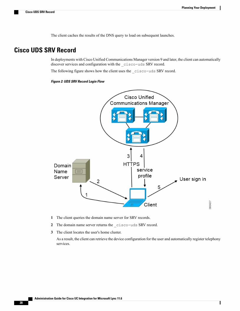
The following figure shows how the client uses the _cisco-uds SRV record.
Figure 2: UDS SRV Record Login Flow
1 The client queries the domain name server for SRV records.
2 The domain name server returns the _cisco-uds SRV record.
3 The client locates the user's home cluster.
As a result, the client can retrieve the device configuration for the user and automatically register telephonyservices.
Administration Guide for Cisco UC Integration for Microsoft Lync 11.628
Planning Your DeploymentCisco UDS SRV Record
In an environment with multiple Cisco Unified Communications Manager clusters, you can configure theIntercluster Lookup Service (ILS). ILS enables the client to find the user's home cluster and discoverservices.
If you do not configure ILS, you must manually configure remote cluster information, similar to theExtension Mobility Cross Cluster (EMCC) remote cluster setup. For more information on remote clusterconfigurations, see the Cisco Unified Communications Manager Features and Services Guide.
Important
4 The client retrieves the user's service profile.
The user's service profile contains the addresses and settings for UC services and client configuration.
The client also determines the authenticator from the service profile.
5 The client signs the user in to the authenticator.
The following is an example of the _cisco-uds SRV record:_cisco-uds._tcp.example.com SRV service location:
priority = 6weight = 30port = 8443svr hostname = cucm3.example.com
_cisco-uds._tcp.example.com SRV service location:priority = 2weight = 20port = 8443svr hostname = cucm2.example.com
_cisco-uds._tcp.example.com SRV service location:priority = 1weight = 5port = 8443svr hostname = cucm1.example.com
Survivable Remote Site TelephonyWhen the Cisco Unified Communication Manager application is unreachable or the WAN is down, use CiscoUnified Survivable Remote Site Telephony (SRST) to retain basic telephony services for your remote users.When connectivity is lost, the client fails over to the local router at the remote site.
SRST versions 8.5 and 8.6 are supported.Note
SRST provides basic call control, when a system is in failover only start, end, hold, resume, mute, unmute,and dual-tone multifrequency signaling [DTMF]) are enabled.
The following services are not available during failover:
• Video
• Mid-call features (transfer, iDivert, call park, conferencing, send to mobile)
• Dial via Office (DvO)
• Ad hoc conferencing
• Binary Floor Control Protocol (BFCP) sharing
Administration Guide for Cisco UC Integration for Microsoft Lync 11.6 29
Planning Your DeploymentSurvivable Remote Site Telephony

For detailed instructions about configuring SRST, see the relevant release of theCisco Unified CommunicationManager Administration Guide.
Audio and Video Performance Reference
The following data is based on testing in a lab environment. This data is intended to provide an idea ofwhat you can expect in terms of bandwidth usage. The content in this topic is not intended to be exhaustiveor to reflect all media scenarios that might affect bandwidth usage.
Attention
Bit Rates for Audio, Video, and Presentation Video
The following table describes bit rates for audio:NotesActual bitrate (kbits per
second)RTP payload in kilobits(kbits) per second
Codec
High quality compressed54/6224/32g.722.1
Standard uncompressed8064g.711
Low quality compressed388g.729a
Bit Rates for Video
The following table describes bit rates for video with g.711 audio:
Measured bit rate (kbits persecond) with g.711 audio
PixelsResolution
156256 x 144w144p
320512 x 288w288pThis is the default size of the videorendering window.
570768 x 448w448p
8901024 x 576w576p
13001280 x 720720p
Notes about the preceding table:
• This table does not list all possible resolutions.
• The measured bit rate is the actual bandwidth used (RTP payload + IP packet overhead).
Bit Rates for Presentation Video
The following table describes the bit rates for presentation video:
Administration Guide for Cisco UC Integration for Microsoft Lync 11.630
Planning Your DeploymentAudio and Video Performance Reference
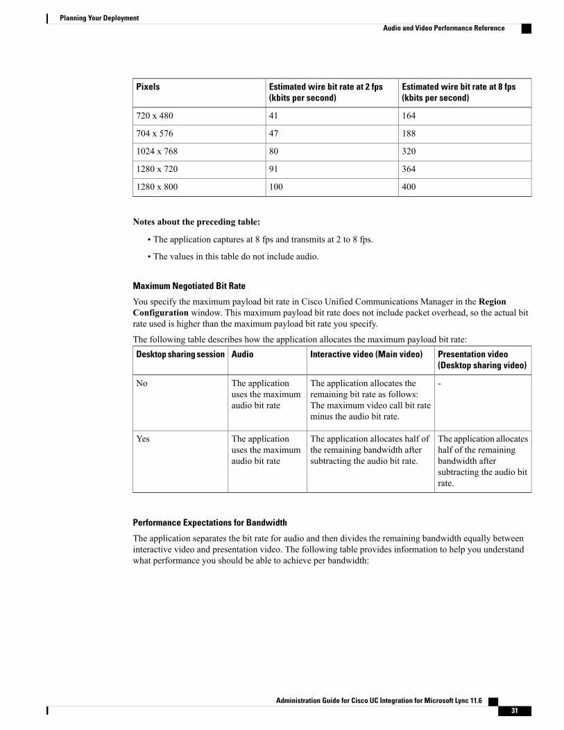
Estimated wire bit rate at 8 fps(kbits per second)
Estimated wire bit rate at 2 fps(kbits per second)
Pixels
16441720 x 480
18847704 x 576
320801024 x 768
364911280 x 720
4001001280 x 800
Notes about the preceding table:
• The application captures at 8 fps and transmits at 2 to 8 fps.
• The values in this table do not include audio.
Maximum Negotiated Bit Rate
You specify the maximum payload bit rate in Cisco Unified Communications Manager in the RegionConfiguration window. This maximum payload bit rate does not include packet overhead, so the actual bitrate used is higher than the maximum payload bit rate you specify.
The following table describes how the application allocates the maximum payload bit rate:Presentation video(Desktop sharing video)
Interactive video (Main video)AudioDesktop sharing session
-The application allocates theremaining bit rate as follows:The maximum video call bit rateminus the audio bit rate.
The applicationuses the maximumaudio bit rate
No
The application allocateshalf of the remainingbandwidth aftersubtracting the audio bitrate.
The application allocates half ofthe remaining bandwidth aftersubtracting the audio bit rate.
The applicationuses the maximumaudio bit rate
Yes
Performance Expectations for Bandwidth
The application separates the bit rate for audio and then divides the remaining bandwidth equally betweeninteractive video and presentation video. The following table provides information to help you understandwhat performance you should be able to achieve per bandwidth:
Administration Guide for Cisco UC Integration for Microsoft Lync 11.6 31
Planning Your DeploymentAudio and Video Performance Reference

Audio + Interactivevideo +Presentation video
Audio +Presentation video(Desktop sharingvideo)
Audio + Interactivevideo (Main video)
AudioUpload speed
Insufficientbandwidth forvideo.
Insufficientbandwidth forvideo.
Insufficientbandwidth forvideo.
At bandwidththreshold for g.711.Sufficientbandwidth forg.729a and g.722.1.
125 kbps underVPN
w144p (256 x 144)at 30 fps + 1280 x720 at 2+ fps
1280 x 800 at 2+ fpsw288p (512 x 288)at 30 fps
Sufficientbandwidth for anyaudio codec.
384 kbps underVPN
w144p (256 x 144)at 30 fps + 1280 x800 at 2+ fps
1280 x 800 at 2+ fpsw288p (512 x 288)at 30 fps
Sufficientbandwidth for anyaudio codec.
384 kbps in anenterprise network
w288p (512 x 288)at 30 fps + 1280 x800 at 8 fps
1280 x 800 at 8 fpsw576p (1024 x 576)at 30 fps
Sufficientbandwidth for anyaudio codec.
1000 kbps
w288p (1024 x 576)at 30 fps + 1280 x800 at 8 fps
1280 x 800 at 8 fpsw720p30 (1280 x720) at 30 fps
Sufficientbandwidth for anyaudio codec.
2000 kbps
Note that VPN increases the size of the payload, which increases the bandwidth consumption.
Video Rate Adaptation
The application uses video rate adaptation to negotiate optimum video quality. Video rate adaptationdynamically increases or decreases video bit rate throughput to handle real-time variations on available IPpath bandwidth.
Users should expect video calls to begin at lower resolution and scale upwards to higher resolution over ashort period of time. The application saves history so that subsequent video calls should begin at the optimalresolution.
Cisco Options Package FilesReview the different Cisco Options Package (COP) files that you might require to deploy the application.
Cisco UnifiedCommunications ManagerVersions
DescriptionCOP File
9.1(2) or laterSupport for Cisco UnifiedCommunications Manager UserData Server (UDS)
cmterm-cucm-uds-912-5.cop.sgn
Administration Guide for Cisco UC Integration for Microsoft Lync 11.632
Planning Your DeploymentCisco Options Package Files
Directory IntegrationDeployment of the application requires directory integration. The following directory integration is supported:
• Enhanced Directory Integration (EDI)
EDI Directory IntegrationEnhanced Directory Integration (EDI) uses native Microsoft Windows APIs to retrieve contact data fromMicrosoft Active Directory.
EDI Configuration
Cisco UC Integration for Microsoft Lync automatically discovers the directory service and connects to aGlobal Catalog if it has been installed on a workstation that is registered to an Active Directory domain. Thisconnection can be customized in the configuration file as follows:
• Attribute mappingsSee Attribute Mapping Parameters.
• Connection settingsSee Directory Connection Parameters.
• Query settingsSee Directory Query Parameters.
• Contact photo resolutionSee Contact Photo Parameters.
• Contact resolutionSee Contact Resolution.
Retrieving Attributes from the Directory
Cisco UC Integration for Microsoft Lync can connect to a Global Catalog or Domain Controller to retrieveActive Directory attributes. Use the following information when determining how the application receivesattributes in your network.
Administration Guide for Cisco UC Integration for Microsoft Lync 11.6 33
Planning Your DeploymentDirectory Integration
Global Catalog
Cisco UC Integration for Microsoft Lync connects to a Global Catalog server by default. If you use thedefault settings, ensure that all attributes reside on your Global Catalog server.
You can replicate attributes to a Global Catalog server using an appropriate tool such as the MicrosoftActive Directory Schema snap-in.
Replicating attributes to your Global Catalog server generates traffic betweenActive Directory servers in the domain.
Note
See the appropriate Microsoft documentation for instructions on replicating attributes to a GlobalCatalog server with the Active Directory Schema snap-in.
Domain Controller
You can configure Cisco UC Integration for Microsoft Lync to connect to a Domain Controller if you:
• Do not want to connect to a Global Catalog server.
• Do not want to replicate attributes to a Global Catalog server.
The application queries only a single domain if you configure it to connect toa Domain Controller.
Note
Specify 1 as the value of the ConnectionType parameter to configure the application to connect to aDomain Controller. See Directory Connection Parameters for more information.
Indexing Attributes
Ensure you index any attributes you use for contact resolution on your directory.
If you use the default attribute mappings, ensure that the following attributes are indexed:
• sAMAccountName
• telephoneNumberAlso, ensure you index the following attributes for secondary number queries:
• otherTelephone
• mobile
• homePhone
By default secondary number queries are enabled in the application. You can disablesecondary number queries with the DisableSecondaryNumberLookups parameter.
Note
Administration Guide for Cisco UC Integration for Microsoft Lync 11.634
Planning Your DeploymentEDI Directory Integration

UDS Directory IntegrationUDS is an interface on Cisco Unified Communications Manager that provides contact resolution. Yousynchronize contact data into Cisco Unified Communications Manager from Microsoft Active Directory oranother LDAP directory source. Cisco UC Integration for Microsoft Lync automatically retrieves that contactdata directly from Cisco Unified Communications Manager using the UDS interface.
Enable Integration with UDS
To enable integration with UDS, you perform the following steps:
1 Create your directory source in Cisco Unified Communications Manager.
2 Synchronize the contact data to Cisco Unified Communications Manager.
3 Specify UDS as the value of the DirectoryServerType parameter in your Cisco UC Integration forMicrosoftLync configuration file.
Contact data resides in Cisco Unified Communications Manager after the synchronization occurs. Theapplication automatically connects to UDS and performs all contact resolution. You do not need to performany other server configuration tasks to use UDS.
Contact Photo Retrieval
Configure the application to retrieve contact photos if you integrate with UDS. For more information, seeContact Photo Retrieval.
Contact Resolution with Multiple Clusters
For contact resolution with multiple Cisco Unified Communications Manager clusters, synchronize all userson the corporate directory to each Cisco Unified Communications Manager cluster. Provision a subset ofthose users on the appropriate Cisco Unified Communications Manager cluster.
For example, your organization has 40,000 users. 20,000 users reside in North America. 20,000 users residein Europe. Your organization has the following Cisco Unified Communications Manager clusters for eachlocation:
• cucm-cluster-na for North America
• cucm-cluster-eu for Europe
In this example, synchronize all 40,000 users to both clusters. Provision the 20,000 users in North Americaon cucu-cluster-na and the 20,000 users in Europe on cucm-cluster-eu.
When users in Europe call users in North America, the application retrieves the contact details for the user inEurope from cucu-cluster-na.
When users in North America call users in Europe, the application retrieves the contact details for the user inNorth America from cucu-cluster-eu.
Supported LDAP Directory ServicesCisco UC Integration for Microsoft Lync supports the following directory services:
Administration Guide for Cisco UC Integration for Microsoft Lync 11.6 35
Planning Your DeploymentUDS Directory Integration

• Microsoft Active Directory 2012
• Microsoft Active Directory 2008
• Microsoft Active Directory 2003
• OpenLDAP
• Active Directory Lightweight Directory Service (AD LDS) or Active Directory Application Mode(ADAM)
• Any server that supports LDAPv3 protocol
Cisco UC Integration forMicrosoft Lync supports the following specific integration scenarios with OpenLDAP,AD LDS, and ADAM:
• OpenLDAP integration using anonymous or authenticated binds.
• Active Directory Lightweight Directory Service (AD LDS) or Active Directory Application Mode(ADAM) integration using anonymous binds, authentication with theMicrosoftWindows principal user,or authentication with the AD LDS principal user.
Evaluate your directory service to determine the characteristics of the schema before configuring Cisco UCIntegration for Microsoft Lync.
Domain Name System ConfigurationCisco UC Integration for Microsoft Lync must connect to a directory service that can access information forall users in the organization. The application typically retrieves the domain name from the USERDNSDOMAINenvironment variable on the user's workstation. This value allows Cisco UC Integration for Microsoft Lyncto locate either the Global Catalog or LDAP service in the domain.
The application automatically connects to the Global Catalog. The application must be configured to locatean LDAP service.
Note
In some instances, the value of the USERDNSDOMAIN environment variable does not resolve to the DNSdomain name that corresponds to the domain name of the entire forest. For example, an instance where thisconfiguration occurs is when an organization uses a sub-domain or resource domain. In such a configuration,the USERDNSDOMAIN environment variable resolves to a child domain, not the parent domain. The resultof this type of configuration is that the application cannot access information for all users in the organization.
If the USERDNSDOMAIN environment variable resolves to a child domain, you can use one of the followingconfiguration options to connect to a service in the parent domain:
• Configure the application to use the FQDN of the parent domain.
To perform this configuration, you specify the FQDN of the parent domain as the value of thePrimaryServerName parameter.
• Configure your DNS server to direct the application to a server that can access all users in the organizationwhen it requests a Global Catalog or LDAP service.
• Ensure that the Global Catalog or LDAP service has access to all users in the organization.
For more information about configuring your DNS server, see the following Microsoft documentation:
Administration Guide for Cisco UC Integration for Microsoft Lync 11.636
Planning Your DeploymentDomain Name System Configuration
• Configuring DNS for the Forest Root Domain
• Assigning the Forest Root Domain Name
• Deploying a GlobalNames Zone
• Support for DNS Namespace planning in Microsoft server products
Quality of Service ConfigurationCisco UC Integration for Microsoft Lync supports two methods for prioritizing and classifying Real-timeTransport Protocol (RTP) traffic as it traverses the network:
• Deploy with Cisco Media Services Interface
• Set DSCP values in IP headers of RTP media packets
We recommend deploying with Cisco Media Services Interface (MSI). This method effectively improvesthe quality of experience and reduces cost of deployment and operations. MSI also enables the client tobecome network aware so it can dynamically adapt to network conditions and integrate more tightly withthe network.
Tip
Cisco Media Services InterfaceCisco Media Services Interface provides a Microsoft Windows service that works with Cisco PrimeCollaborationManager and CiscoMedianet-enabled routers to ensure that Cisco UC Integration forMicrosoftLync can send audio media and video media on your network with minimum latency or packet loss.
Before Cisco UC Integration for Microsoft Lync sends audio media or video media, it checks for CiscoMediaServices Interface.
• If the service exists on the computer, Cisco UC Integration for Microsoft Lync provides flow informationto Cisco Media Services Interface. The service then signals the network so that routers classify the flowand provide priority to the Cisco UC Integration for Microsoft Lync traffic.
• If the service does not exist, Cisco UC Integration for Microsoft Lync does not use it and sends audiomedia and video media as normal.
Cisco UC Integration for Microsoft Lync checks for Cisco Media Services Interface for each audio callor video call.
Note
You must install Cisco Media Services Interface separately and ensure your network is enabled for CiscoMedianet. You must also install Cisco Prime Collaboration Manager and routers enabled for Cisco Medianet.
Administration Guide for Cisco UC Integration for Microsoft Lync 11.6 37
Planning Your DeploymentQuality of Service Configuration
Set DSCP ValuesSet Differentiated Services Code Point (DSCP) values in RTP media packet headers to prioritize Cisco UCIntegration for Microsoft Lync traffic as it traverses the network.
Port Ranges on Cisco Unified Communications ManagerYou define the port range that the client uses on the SIP profile in Cisco Unified Communications Manager.The client then uses this port range to send RTP traffic across the network.
Specify a Port Range on the SIP Profile
To specify a port range for the client to use for RTP traffic, do the following:
Procedure
Step 1 Open the Cisco Unified CM Administration interface.Step 2 Select Device > Device Settings > SIP Profile.Step 3 Find the appropriate SIP profile or create a new SIP profile.
The SIP Profile Configuration window opens.
Step 4 Specify the port range in the following fields:
Start Media Port
Defines the start port for media streams. This field sets the lowest port in the range.
Stop Media Port
Defines the stop port for media streams. This field sets the highest port in the range.
Step 5 Select Apply Config and then OK.
How the Client Uses Port Ranges
Cisco UC Integration for Microsoft Lync equally divides the port range that you set in the SIP profile. Theclient then uses the port range as follows:
• Lower half of the port range for audio streams
• Upper half of the port range for video streams
For example, if you use a start media port of 3000 and an end media port of 4000, the client sends mediathrough ports as follows:
• Ports 3000 to 3501 for audio streams
• Ports 3502 to 4000 for video streams
Administration Guide for Cisco UC Integration for Microsoft Lync 11.638
Planning Your DeploymentSet DSCP Values

As a result of splitting the port range for audio media and video media, the client creates identifiable mediastreams. You can then classify and prioritize those media streams by setting DSCP values in the IP packetheaders.
Options for Setting DSCP ValuesMethods for setting DSCP values:
• Set DSCP values with Microsoft Group Policy
• Set DSCP values on network switches and routers
Set DSCP Values with Group Policy
If you deploy Cisco UC Integration for Microsoft Lync on a laterWindows operating system such asMicrosoftWindows 7, you can use Microsoft Group Policy to apply DSCP values.
Complete the steps in the following Microsoft support article to create a group policy: http://technet.microsoft.com/en-us/library/cc771283%28v=ws.10%29.aspx
You should create separate policies for audio media and video media with the following attributes:Signaling PolicyVideo PolicyAudio PolicyAttributes
CUCILync.exeCUCILync.exeCUCILync.exeApplication name
TCPUDPUDPProtocol
5060 for SIP5061 for secure SIP
Corresponding portnumber or range fromthe SIP profile on CiscoUnifiedCommunicationsManager.
Corresponding portnumber or range fromthe SIP profile on CiscoUnifiedCommunicationsManager.
Port number or range
243446DSCP value
Set DSCP Values on the Network
You can configure switches and routers to mark DSCP values in the IP headers of RTP media.
To set DSCP values on the network, you must identify the different streams from the client application.
Media Streams
Because the client uses different port ranges for audio streams and video streams, you can differentiateaudio media and video media based on those port range. Using the default port ranges in the SIP profile,you should mark media packets as follows:
• Audio media streams in ports from 16384 to 24574 as EF
• Video media streams in ports from 24575 to 32766 as AF41
Administration Guide for Cisco UC Integration for Microsoft Lync 11.6 39
Planning Your DeploymentSet DSCP Values

Signaling Streams
You can identify signaling between the client and servers based on the various ports required for SIP,CTI QBE, and XMPP. For example, SIP signaling between Cisco UC Integration for Microsoft Lyncand Cisco Unified Communications Manager occurs through port 5060.
You should mark signaling packets as AF31.
Administration Guide for Cisco UC Integration for Microsoft Lync 11.640
Planning Your DeploymentSet DSCP Values

C H A P T E R 4Setup Certificate Validation
Cisco UC Integration for Microsoft Lync uses certificate validation to establish secure connections withservers.
Servers present Cisco UC Integration for Microsoft Lync with certificates when attempting to establishsecure connections. Cisco UC Integration for Microsoft Lync validates those certificates against certificatesin the Microsoft Windows certificate store. If the client cannot validate a certificate, it prompts the user toconfirm if they want to accept the certificate.
• Required Certificates, page 41
• Get Certificates Signed by Certificate Authority, page 42
• Server Identity in Certificates, page 43
• Import Root Certificates on Client Computers, page 43
Required CertificatesThe following certificates are presented to establish a secure connection.
CertificateServer
HTTP (Tomcat)Cisco Unified Communications Manager
HTTP (Tomcat)Cisco Unity Connection
HTTP (Tomcat)Cisco WebEx Meetings Server
Server certificate (used for HTTP, XMPP, and SIPcall signaling)
Cisco VCS Expressway
Cisco Expressway-E
Important Notes
• Every node in a cluster, including both subscribers and publishers, run a Tomcat service and can presentthe client with an HTTP certificate. You should plan to sign the certificates for each node in the cluster.
Administration Guide for Cisco UC Integration for Microsoft Lync 11.6 41
• To secure SIP signaling between the client and Cisco Unified Communications Manager, you shoulduse Certification Authority Proxy Function (CAPF) enrollment.
Get Certificates Signed by Certificate AuthorityCisco recommends using server certificates that are signed by one of the following types of Certificate Authority(CA):
• Public CAA third-party company verifies the server identity and issues a trusted certificate.
• Private CAYou create and manage a local CA and issue trusted certificates.
The signing process varies for each server and can vary between server versions. It is beyond the scope ofthis document to provide detailed steps for every version of each server. You should consult the appropriateserver documentation for detailed instructions on how to get certificates signed by a CA. However, thefollowing steps provide a high-level overview of the procedure.
Procedure
Step 1 Generate a Certificate Signing Request (CSR) on each server that can present a certificate to the client.Step 2 Submit each CSR to the CA.Step 3 Upload the certificates that the CA issues to each server.
Certificate Signing Request Forms and RequirementsPublic CAs typically require CSRs to conform to specific formats. For example, a public CA might onlyaccept CSRs that:
• Are Base64-encoded.
• Do not contain certain characters, such as @&! , in the Organization, OU, or other fields.
• Use specific bit lengths in the server's public key.
Likewise, if you submit CSRs frommultiple nodes, public CAsmight require that the information is consistentin all CSRs.
To prevent issues with your CSRs, you should review the format requirements from the public CA to whichyou plan to submit the CSRs. You should then ensure that the information you enter when configuring yourserver conforms to the format that the public CA requires.
One Certificate Per FQDN: Some public CAs sign only one certificate per fully qualified domain name(FQDN).
Administration Guide for Cisco UC Integration for Microsoft Lync 11.642
Setup Certificate ValidationGet Certificates Signed by Certificate Authority

Server Identity in CertificatesThe CA specifies the server identity in the certificate as part of the signing process. When the client validatesthat certificate, it checks that:
• A trusted authority has issued the certificate.
• The identity of the server that presents the certificate matches the identity of the server specified in thecertificate.
Public CAs generally require a fully qualified domain name (FQDN) as the server identity, not an IPaddress.
Note
Identifier Fields
The client checks the following identifier fields in server certificates for an identity match:
• HTTP certificates
◦SubjectAltName\dnsNames
◦Subject CN
The Subject CN field can contain a wildcard ( *) as the leftmost character, for example, *.cisco.com.Tip
Prevent Identity Mismatch
If users attempt to connect to a server with an IP address, and the server certificate identifies the server withan FQDN, the client cannot identify the server as trusted and prompts the user.
If your server certificates identify the servers with FQDNs, you should plan to specify each server name asFQDN throughout your environment.
Import Root Certificates on Client ComputersEvery server certificate should have an associated root certificate present in the trust store on client computers.CiscoUC Integration forMicrosoft Lync validates the certificates that servers present against the root certificatesin the trust store.
If you get server certificates signed by a public CA, the public CA should already have a root certificatepresent in the trust store on the client computer. In this case, you do not need to import root certificates onthe client computers.
You should import root certificates into the Microsoft Windows certificate store if:
• The certificates are signed by a CA that does not already exist in the trust store, such as a private CA.
◦Import the private CA certificate to the Trusted Root Certification Authorities store.
• The certificates are self-signed.
Administration Guide for Cisco UC Integration for Microsoft Lync 11.6 43
Setup Certificate ValidationServer Identity in Certificates
Import self-signed certificates to the Enterprise Trust store.◦
If root certificates are not present in the trust store, Cisco UC Integration for Microsoft Lync promptsusers to accept certificates from each server in your environment.
Important
When the client prompts users to accept a certificate, users can:
• Accept the certificate
◦The client saves the certificate to the Enterprise Trust store.
• Decline the certificate
◦The client
◦Does not save the certificate.
◦Does not connect to the server.
◦Displays an error notification.
When users restart the client, it prompts them to accept the certificate again.
You can use any appropriate method to import certificates into the Microsoft Windows certificate store,including the following. For detailed instructions on importing certificates, refer to the appropriate Microsoftdocumentation.
• Use the Certificate Import Wizard to import certificates individually.
• Deploy certificates to users with the CertMgr.exe command line tool on Microsoft Windows Server.
This option requires you to use the Certificate Manager tool, CertMgr.exe, not theCertificates Microsoft Management Console, CertMgr.msc.
Note
• Deploy certificates to users with a Group Policy object (GPO) on Microsoft Windows Server.
Administration Guide for Cisco UC Integration for Microsoft Lync 11.644
Setup Certificate ValidationImport Root Certificates on Client Computers
C H A P T E R 5Server Setup
This section provides task-based information to guide you through the server setup process.
Providing information on every task involved in installing and configuring Cisco Unified CommunicationsManager is beyond the scope of this document. The purpose of this chapter is to provide a high-levelworkflow of the tasks you should complete to set up your environment. See the appropriate documentationfor Cisco Unified Communications Manager to review detailed information and ensure you complete theinstallation and configuration tasks specific to your deployment.
Note
You must install and configure Cisco Unified Communications Manager before you begin any tasks in thissection.
• Review the Setup Process, page 46
• Add a Directory to Your Environment, page 46
• Create a Service Profile, page 47
• Create Software Phone Devices, page 48
• Create Desk Phone Devices, page 56
• URI Dialing, page 62
• Call Pickup, page 65
• Hunt Group, page 70
• Configure User Associations, page 74
• TFTP Server Address Options, page 75
• Reset Devices, page 75
• Create a CCMCIP Profile, page 76
Administration Guide for Cisco UC Integration for Microsoft Lync 11.6 45

Review the Setup ProcessThis topic provides a high-level overview of the process to set up your environment with Cisco UnifiedCommunications Manager.
Procedure
Step 1 Add a directory to your environment.Adding a directory to your environment does the following:
• Populates the Cisco Unified Communications Manager database with user data that resides on yourdirectory server.
• Provides Cisco Unified Communications Manager with users in your environment who you can add toprofiles and to whom you can provision capabilities.
Step 2 Set up unified communications.a) Create software phone devices.b) Create desk phone devices.
Step 3 (Optional) Set up voicemail.
Add a Directory to Your EnvironmentAdding a directory to your environment populates the Cisco Unified CommunicationsManager database withuser data that resides on your directory server. Completing this task provides Cisco Unified CommunicationsManager with users in your environment who you can add to profiles and to whom you can provisioncapabilities.
Procedure
Step 1 Open the Cisco Unified CM Administration interface.Step 2 Select System > LDAP > LDAP System.
The LDAP System Configuration window opens.
Step 3 Locate the LDAP System Information section.Step 4 Select Enable Synchronizing from LDAP Server.Step 5 Select the appropriate values from the following drop-down lists:
• LDAP Server Type
• LDAP Attribute for User ID
Step 6 Select System > LDAP > LDAP Directory.Step 7 Select Add New.
Administration Guide for Cisco UC Integration for Microsoft Lync 11.646
Server SetupReview the Setup Process
The LDAP Directory window opens.
Step 8 Specify the required details on the LDAP Directory window.See the LDAP integration topics in the Cisco Unified Communications Manager Administration Guide formore information about the values and formats you can specify.
Step 9 Select Save.Step 10 Select Peform Full Sync Now.
The amount of time it takes for the synchronization process to complete depends on the number ofusers that exist in your directory. If you synchronize a large directory with thousands of users, youshould expect the process to take some time.
Note
User data from your directory server is synchronized to the Cisco Unified CommunicationsManager database.Cisco Unified Communications Manager then synchronizes the user data to the Cisco Unified Presencedatabase.
What to Do Next
Verify that users from your directory are available on Cisco Unified Communications Manager and CiscoUnified Presence.
If users from your directory are returned in the list of available users, you have successfully added a directoryto your environment.
Related Topics
Configuring Cisco Unified Communication Manager Directory IntegrationLDAP Directory ConfigurationIntegrating the LDAP Directory
Create a Service ProfileYou create a service profile that contains the configuration settings for the services you add on Cisco UnifiedCommunications Manager. You add the service profile to the end user configuration for your Cisco UCIntegration for Microsoft Lync users. Cisco UC Integration for Microsoft Lync can then retrieve settings foravailable services from the service profile.
Before You Begin
Review the following prerequisites before completing this task:
• Service Profile creation is only available in Cisco Unified Communications Manager 9.0.1 and later.
• Review the Service profile setup section of the Cisco Unified Communications Manager AdministrationGuide for specific details about creating service profiles.
Procedure
Step 1 Open the Cisco Unified CM Administration interface.Step 2 Select User Management > User Settings > Service Profile.
Administration Guide for Cisco UC Integration for Microsoft Lync 11.6 47
Server SetupCreate a Service Profile
The Find and List Service Profiles window opens.
Step 3 Select Add New.The Service Profile Configuration window opens.
Step 4 Enter settings on the Service Profile Configuration window as follows:a) Specify a unique name for the service profile in the Name field.b) Specify an optional description in the Description field.c) SelectMake this the default service profile for the system, if appropriate.
Step 5 Select Save.
Create Software Phone Devices
Create CSF DevicesComplete the steps in this task to create CSF devices.
Procedure
Step 1 Open the Cisco Unified CM Administration interface.Step 2 Select Device > Phone.
The Find and List Phones window opens.
Step 3 Select Add New.Step 4 SelectCisco Unified Client Services Framework from the Phone Type drop-down list and then selectNext.
The Phone Configuration window opens.
Step 5 Specify a name for the CSF device in the Device Name field.You should use the CSFusername format for CSF device names. For example, you create a CSF device fora user named Tanya Adams, whose username is tadams. In this case, you should specify CSFtadams as thedevice name.
Step 6 Specify configuration settings on the Phone Configuration window as appropriate.See the Phone Setup topic in the Cisco Unified CommunicationsManager documentation for more informationabout the configuration settings on the Phone Configuration window.
Step 7 Select Save.A message displays to inform you if the device is added successfully. The Association Information sectionbecomes available on the Phone Configuration window.
What to Do Next
Add a directory number to the device and apply the configuration.
Administration Guide for Cisco UC Integration for Microsoft Lync 11.648
Server SetupCreate Software Phone Devices
Video Desktop SharingBinary Floor Control Protocol (BFCP) provides video desktop sharing capabilities for software phone devices,also known as CSF devices. Cisco Unified Communications Manager handles the BFCP packets that userstransmit when using video desktop sharing capabilities. On Cisco Unified Communications Manager version9.0(1) and later, BFCP presentation sharing is automatically enabled. For this reason, you do not need toperform any steps to enable video desktop sharing on CSF devices.
• You can enable video desktop sharing only on software phone devices. You cannot enable video desktopsharing on desk phone devices.
• Users must be on active calls to use video desktop sharing capabilities. You can only initiate videodesktop sharing sessions from active calls.
You must enable BFCP on the SIP trunk to allow video desktop sharing capabilities outside of a CiscoUnified Communications Manager cluster. To enable BFCP on the SIP trunk, do the following:
Tip
1 Select Allow Presentation Sharing using BFCP in the Trunk Specific Configuration section of theSIP profile.
2 Select the SIP profile from the SIP Profile drop-down list on the CSF device configuration.
Set Up Secure Phone Capabilities
Configure the Security ModeTo use secure phone capabilities, configure the Cisco Unified Communications Manager security mode usingthe Cisco CTL Client. You cannot use secure phone capabilities with the non secure security mode. At aminimum, you must use mixed mode security.
Mixed mode security:
• Allows authenticated, encrypted, and non secure phones to register with Cisco Unified CommunicationsManager.
• Cisco Unified Communications Manager supports both RTP and SRTP media.
• Authenticated and encrypted devices use secure port 5061 to connect to Cisco Unified CommunicationsManager.
See the Cisco Unified Communications Manager Security Guide for instructions on configuring mixed modewith the Cisco CTL Client.
Create a Phone Security ProfileThe first step to setting up secure phone capabilities is to create a phone security profile that you can applyto the device.
Administration Guide for Cisco UC Integration for Microsoft Lync 11.6 49
Server SetupVideo Desktop Sharing
Before You Begin
Configure the Cisco Unified Communications Manager security to use mixed mode.
Procedure
Step 1 Select System > Security > Phone Security Profile.Step 2 Select Add New.Step 3 Select the appropriate phone security profile from the Phone Security Profile type drop-down list and select
Next.The Phone Security Profile Configuration window opens.
Configure the Phone Security ProfileAfter you add a phone security profile, you must configure it to suit your requirements.
Procedure
Step 1 Specify a name for the phone security profile in the Name field on the Phone Security Profile Configurationwindow.
Youmust use fully qualified domain name (FQDN) format for the security profile name if usersconnect remotely to the corporate network through Expressway forMobile and Remote Access.
Restriction
Step 2 Specify values for the phone security profile as follows:
• Device Security Mode— Select one of the following:
• Authenticated
• Encrypted
• Transport Type— Leave the default value of TLS.
• Authentication Mode— Select By Authentication String.
• Key Size (Bits)— Select the appropriate key size for the certificate.Key size refers to the bit length of the public and private keys that the client generates duringthe CAPF enrollment process.
The client has been tested using authentication strings with 1024 bit length keys. The clientrequires more time to generate 2048 bit length keys than 1024 bit length keys. As a result, ifyou select 2048, you should expect it to take longer to complete the CAPF enrollment process.
Note
• SIP Phone Port— Leave the default value. The client always uses port 5061 to connect to Cisco UnifiedCommunications Manager when you apply a secure phone profile. The port that you specify in this fieldonly takes effect if you select Non Secure as the value for Device Security Mode.
Step 3 Select Save.
Administration Guide for Cisco UC Integration for Microsoft Lync 11.650
Server SetupSet Up Secure Phone Capabilities
Configure CSF DevicesAdd the phone security profile to the devices and complete other configuration tasks for secure phonecapabilities.
Procedure
Step 1 Open the CSF device configuration window.a) Select Device > Phone.
The Find and List Phones window opens.
b) Specify the appropriate filters in the Find Phone where field and then select Find to retrieve a list ofdevices.
c) Select the CSF device from the list.The Phone Configuration window opens.
Step 2 Select Allow Control of Device from CTI in the Device Information section.Step 3 Select Save.Step 4 Locate the Protocol Specific Information section.Step 5 Select the phone security profile from the Device Security Profile drop-down list.Step 6 Select Save.
At this point in the secure phone set up, existing users can no longer use their CSF devices. Youmust completethe secure phone set up for users to be able to access their CSF devices.
What to Do Next
Specify the certificate settings and generate the authentication string for users.
Specify Certificate Settings
Procedure
Step 1 Locate the Certification Authority Proxy Function (CAPF) Information section on the Phone Configurationwindow.
Step 2 Specify values as follows:
• Certificate Operation— Select Install/Upgrade.
• Authentication Mode— Select By Authentication String.
• Key Size (Bits)— Select the same key size that you set in the phone security profile.
• Operation Completes By— Specify an expiration value for the authentication string or leave as default.
Administration Guide for Cisco UC Integration for Microsoft Lync 11.6 51
Server SetupSet Up Secure Phone Capabilities
Step 3 Select Save.Step 4 To create the authentication string you can do one of the following:
• Select Generate String in the Certification Authority Proxy Function (CAPF) Information section.
• Enter a custom string in the Authentication String field.
What to Do Next
Provide users with the authentication string.
Provide Users with Authentication StringsUsers must specify the authentication string in the client interface to access their devices and securely registerwith Cisco Unified Communications Manager.
When users enter the authentication string in the client interface, the CAPF enrollment process begins.
The time it takes for the enrollment process to complete can vary depending on the user's computer ormobile device and the current load for Cisco Unified Communications Manager. It can take up to oneminute for the client to complete the CAPF enrollment process.
Note
The client displays an error if:
• Users enter an incorrect authentication string.Users can attempt to enter authentication strings again to complete the CAPF enrollment. However, ifa user continually enters an incorrect authentication string, the client might reject any string the userenters, even if the string is correct. In this case, you must generate a new authentication string on theuser's device and then provide it to the user.
• Users do not enter the authentication string before the expiration time you set in theOperationCompletesBy field.
In this case, you must generate a new authentication string on the user's device. The user must then enterthat authentication string before the expiration time.
When you configure the end users in Cisco Unified Communications Manager, you must add them to thefollowing user groups:
Important
• Standard CCM End Users
• Standard CTI Enabled
Users must not belong to the Standard CTI Secure Connection user group.
Administration Guide for Cisco UC Integration for Microsoft Lync 11.652
Server SetupSet Up Secure Phone Capabilities
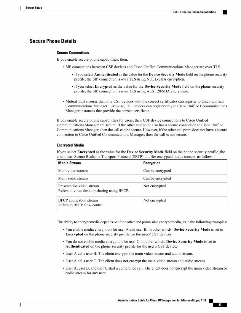
Secure Phone Details
Secure Connections
If you enable secure phone capabilities, then:
• SIP connections between CSF devices and Cisco Unified Communications Manager are over TLS.
• If you selectAuthenticated as the value for theDevice SecurityMode field on the phone securityprofile, the SIP connection is over TLS using NULL-SHA encryption.
• If you select Encrypted as the value for the Device Security Mode field on the phone securityprofile, the SIP connection is over TLS using AES 128/SHA encryption.
• Mutual TLS ensures that only CSF devices with the correct certificates can register to Cisco UnifiedCommunications Manager. Likewise, CSF devices can register only to Cisco Unified CommunicationsManager instances that provide the correct certificate.
If you enable secure phone capabilities for users, their CSF device connections to Cisco UnifiedCommunications Manager are secure. If the other end point also has a secure connection to Cisco UnifiedCommunications Manager, then the call can be secure. However, if the other end point does not have a secureconnection to Cisco Unified Communications Manager, then the call is not secure.
Encrypted Media
If you select Encrypted as the value for the Device Security Mode field on the phone security profile, theclient uses Secure Realtime Transport Protocol (SRTP) to offer encrypted media streams as follows:
EncryptionMedia Stream
Can be encryptedMain video stream
Can be encryptedMain audio stream
Not encryptedPresentation video streamRefers to video desktop sharing using BFCP.
Not encryptedBFCP application streamRefers to BFCP flow control.
The ability to encrypt media depends on if the other end points also encrypt media, as in the following examples:
• You enable media encryption for user A and user B. In other words, Device Security Mode is set toEncrypted on the phone security profile for the users' CSF devices.
• You do not enable media encryption for user C. In other words, Device Security Mode is set toAuthenticated on the phone security profile for the user's CSF device.
• User A calls user B. The client encrypts the main video stream and audio stream.
• User A calls user C. The client does not encrypt the main video stream and audio stream.
• User A, user B, and user C start a conference call. The client does not encrypt the main video stream oraudio stream for any user.
Administration Guide for Cisco UC Integration for Microsoft Lync 11.6 53
Server SetupSet Up Secure Phone Capabilities

The client displays a lock icon when it can use SRTP for encrypted media streams to other secured clientsor conference bridges.
However, not all versions of Cisco Unified Communications Manager provide the ability to display thelock icon. If the version of Cisco Unified Communications Manager you are using does not provide thisability, the client cannot display a lock icon even when it sends encrypted media.
Note
Using Expressway for Mobile and Remote Access
Users cannot complete the enrollment process or use secure phone capabilities from outside the corporatenetwork. This limitation also includes when users connects through Expressway for Mobile and RemoteAccess; for example,
1 You configure a user's CSF device for secure phone capabilities.
2 That user connects to the internal corporate network through Expressway for Mobile and Remote Access.
3 The client notifies the user that it cannot use secure phone capabilities instead of prompting the user toenter an authentication string.
When users connect to the internal network through Expressway forMobile and Remote Access and participatein a call:
• Media is encrypted on the call path between the Cisco Expressway-C and devices that are registered tothe Cisco Unified Communications Manager using Expressway for Mobile and Remote Access.
• Media is not encrypted on the call path between the Cisco Expressway-C and devices that are registeredlocally to Cisco Unified Communications Manager.
If you change the phone security profile while the client is connected through Expressway for Mobile andRemote Access, you must restart the client for that change to take effect.
Note
Conference Calls
On conference, or multi-party, calls, the conferencing bridge must support secure phone capabilities. If theconferencing bridge does not support secure phone capabilities, calls to that bridge are not secure. Likewise,all parties must support a common encryption algorithm for the client to encrypt media on conference calls.
CSF device security reverts to the lowest level available on multi-party calls. For example, user A, user B,and user C join a conference call. User A and user B have CSF devices with secure phone capabilities. UserC has a CSF device without secure phone capabilities. In this case, the call is not secure for all users.
Sharing Secure CSF Devices between Clients
Clients that do not support secure phone capabilities cannot register to secure CSF devices.
Administration Guide for Cisco UC Integration for Microsoft Lync 11.654
Server SetupSet Up Secure Phone Capabilities

Multiple Users on a Shared Microsoft Windows Account
Multiple users can have unique credentials for the client and share the same Windows account. However, thesecure CSF devices are restricted to the Windows account that the users share. Users who share the sameWindows account cannot make calls with their secure CSF devices from different Windows accounts.
You should ensure that multiple users who share the same Windows account have CSF devices with uniquenames. Users cannot register their CSF devices if they share the sameWindows account and have CSF deviceswith identical names, but connect to different Cisco Unified Communications Manager clusters.
For example, user A has a CSF device named CSFcompanyname and connects to cluster 1. User B has a CSFdevice named CSFcompanyname and connects to cluster 2. In this case, a conflict occurs for both CSF devices.Neither user A or user B can register their CSF devices after both users log in to the same Windows account.
Multiple Users on a Shared Computer
The client caches the certificates for each user's secure CSF device in a location that is unique to eachWindowsuser. When a user logs in to their Windows account on the shared computer, that user can access only thesecure CSF device that you provision to them. That user cannot access the cached certificates for otherWindowsusers.
Add Directory Number to the Device for Desktop ApplicationsYou must add directory numbers to devices in Cisco Unified Communications Manager. This topic providesinstructions on adding directory numbers using theDevice > Phonemenu option after you create your device.Under this menu option, only the configuration settings that apply to the phone model or CTI route pointdisplay. See the Cisco Unified CommunicationsManager documentation for more information about differentoptions to configure directory numbers.
Procedure
Step 1 Locate the Association Information section on the Phone Configuration window.Step 2 Select Add a new DN.Step 3 Specify a directory number in the Directory Number field.Step 4 Specify all other required configuration settings as appropriate.Step 5 Associate end users with the directory number as follows:
a) Locate the Users Associated with Line section.b) Select Associate End Users.c) Specify the appropriate filters in the Find User where field and then select Find to retrieve a list of users.d) Select the appropriate users from the list.e) Select Add Selected.
The selected users are added to the voicemail profile.
Step 6 Select Save.Step 7 Select Apply Config.Step 8 Follow the prompts on the Apply Configuration window to apply the configuration.
Administration Guide for Cisco UC Integration for Microsoft Lync 11.6 55
Server SetupAdd Directory Number to the Device for Desktop Applications

Create Desk Phone DevicesUsers can control desk phones on their computers to place audio calls.
Before You Begin
Create software phone devices.
Procedure
Step 1 Open the Cisco Unified CM Administration interface.Step 2 Select Device > Phone.
The Find and List Phones window opens.
Step 3 Select Add New.Step 4 Select the appropriate device from the Phone Type drop-down list and then select Next.
The Phone Configuration window opens.
Step 5 Complete the following steps in the Device Information section:a) Enter a meaningful description in the Description field.
The client displays device descriptions to users. If users have multiple devices of the same model, thedescriptions help users tell the difference between multiple devices.
b) Select Allow Control of Device from CTI.If you do not select Allow Control of Device from CTI, users cannot control the desk phone.
Step 6 Complete the following steps to enable desk phone video capabilities:a) Locate the Product Specific Configuration Layout section.b) Select Enabled from the Video Capabilities drop-down list.
If possible, you should enable desk phone video capabilities on the device configuration. However,certain phone models do not include the Video Capabilities drop-down list at the deviceconfiguration level. In this case, you should open the Common Phone Profile Configurationwindow and then select Enabled from the Video Calling drop-down list.
Note
See Desk Phone Video Configuration for more information about desk phone video.
Step 7 Specify all other configuration settings on the Phone Configuration window as appropriate.See the Cisco Unified CommunicationsManager documentation for more information about the configurationsettings on the Phone Configuration window.
Step 8 Select Save.An message displays to inform you if the device is added successfully. The Association Information sectionbecomes available on the Phone Configuration window.
What to Do Next
Add a directory number to the device and apply the configuration.
Administration Guide for Cisco UC Integration for Microsoft Lync 11.656
Server SetupCreate Desk Phone Devices

Desk Phone Video ConfigurationDesk phone video capabilities let users receive video transmitted to their desk phone devices on their computersthrough the client.
Set Up Desk Phone Video
To set up desk phone video, you must complete the following steps:
1 Physically connect the computer to the computer port on the desk phone device.
You must physically connect the computer to the desk phone device through the computer port so that theclient can establish a connection to the device. You cannot use desk phone video capabilities with wirelessconnections to desk phone devices.
If users have both wireless and wired connections available, they should configure Microsoft Windowsso that wireless connections do not take priority over wired connections. See the following Microsoftdocumentation for more information: An explanation of the Automatic Metric feature for Internet Protocolroutes.
Tip
2 Enable the desk phone device for video in Cisco Unified Communications Manager.
3 Install Cisco Media Services Interface on the computer.
Cisco Media Services Interface provides the Cisco Discover Protocol (CDP) driver that enables the clientto do the following:
• Discover the desk phone device.
• Establish and maintain a connection to the desk phone device using the CAST protocol.
Download the Cisco Media Services Interface installation program from the download site oncisco.com.
Note
Desk Phone Video Considerations
Review the following considerations and limitations before you provision desk phone video capabilities tousers:
• You cannot use desk phone video capabilities on devices if video cameras are attached to the devices,such as a Cisco Unified IP Phone 9971. You can use desk phone video capabilities if you remove videocameras from the devices.
• You cannot use desk phone video capabilities with devices that do not support CTI.
• Video desktop sharing, using the BFCP protocol, is not supported with desk phone video.
• It is not possible for endpoints that use SCCP to receive video only. SCCP endpoints must send andreceive video. Instances where SCCP endpoints do not send video result in audio only calls.
Administration Guide for Cisco UC Integration for Microsoft Lync 11.6 57
Server SetupDesk Phone Video Configuration

• 7900 series phones must use SCCP for desk phone video capabilities. 7900 series phones cannot useSIP for desk phone video capabilities.
• If a user initiates a call from the keypad on a desk phone device, the call starts as an audio call on thedesk phone device. The client then escalates the call to video. For this reason, you cannot make videocalls to devices that do not support escalation, such as H.323 endpoints. To use desk phone videocapabilities with devices that do not support escalation, users should initiate calls from the client.
• A compatibility issue exists with Cisco Unified IP Phones that use firmware version SCCP45.9-2-1S.You must upgrade your firmware to version SCCP45.9-3-1 to use desk phone video capabilities.
• Some antivirus or firewall applications, such as Symantec EndPoint Protection, block inbound CDPpackets, which disables desk phone video capabilities. You should configure your antivirus or firewallapplication to allow inbound CDP packets.
See the following Symantec technical document for additional details about this issue: Cisco IP Phoneversion 7970 and Cisco Unified Video Advantage is Blocked by Network Threat Protection.
• You must not select theMedia Termination Point Required checkbox on the SIP trunk configurationfor Cisco Unified Communications Manager. Desk phone video capabilities are not available if youselect this checkbox.
Desk Phone Video Troubleshooting
If you encounter an error that indicates desk phone video capabilities are unavailable or the desk phone deviceis unknown, do the following:
1 Ensure you enable the desk phone device for video in Cisco Unified Communications Manager.
2 Reset the physical desk phone.
3 Exit the client.
4 Run services.msc on the computer where you installed the client.
5 Restart Cisco Media Services Interface.
6 Restart the client.
Add Directory Number to the Device for Desktop ApplicationsYou must add directory numbers to devices in Cisco Unified Communications Manager. This topic providesinstructions on adding directory numbers using theDevice > Phonemenu option after you create your device.Under this menu option, only the configuration settings that apply to the phone model or CTI route pointdisplay. See the Cisco Unified CommunicationsManager documentation for more information about differentoptions to configure directory numbers.
Administration Guide for Cisco UC Integration for Microsoft Lync 11.658
Server SetupAdd Directory Number to the Device for Desktop Applications
Procedure
Step 1 Locate the Association Information section on the Phone Configuration window.Step 2 Select Add a new DN.Step 3 Specify a directory number in the Directory Number field.Step 4 Specify all other required configuration settings as appropriate.Step 5 Associate end users with the directory number as follows:
a) Locate the Users Associated with Line section.b) Select Associate End Users.c) Specify the appropriate filters in the Find User where field and then select Find to retrieve a list of users.d) Select the appropriate users from the list.e) Select Add Selected.
The selected users are added to the voicemail profile.
Step 6 Select Save.Step 7 Select Apply Config.Step 8 Follow the prompts on the Apply Configuration window to apply the configuration.
Enable Video Rate AdaptationThe client uses video rate adaptation to negotiate optimum video quality. Video rate adaptation dynamicallyincreases or decreases video quality based on network conditions.
To use video rate adaptation, you must enable Real-Time Transport Control Protocol (RTCP) on Cisco UnifiedCommunications Manager.
RTCP is enabled on software phone devices by default. However, you must enable RTCP on desk phonedevices.
Note
Enable RTCP on Common Phone ProfilesYou can enable RTCP on a common phone profile to enable video rate adaptation on all devices that use theprofile.
Procedure
Step 1 Open the Cisco Unified CM Administration interface.Step 2 Select Device > Device Settings > Common Phone Profile.
Administration Guide for Cisco UC Integration for Microsoft Lync 11.6 59
Server SetupEnable Video Rate Adaptation

The Find and List Common Phone Profiles window opens.
Step 3 Specify the appropriate filters in the Find Common Phone Profile where field and then select Find to retrievea list of profiles.
Step 4 Select the appropriate profile from the list.The Common Phone Profile Configuration window opens.
Step 5 Locate the Product Specific Configuration Layout section.Step 6 Select Enabled from the RTCP drop-down list.Step 7 Select Save.
Enable RTCP on Device ConfigurationsYou can enable RTCP on specific device configurations instead of a common phone profile. The specificdevice configuration overrides any settings you specify on the common phone profile.
Procedure
Step 1 Open the Cisco Unified CM Administration interface.Step 2 Select Device > Phone.
The Find and List Phones window opens.
Step 3 Specify the appropriate filters in the Find Phone where field and then select Find to retrieve a list of phones.Step 4 Select the appropriate phone from the list.
The Phone Configuration window opens.
Step 5 Locate the Product Specific Configuration Layout section.Step 6 Select Enabled from the RTCP drop-down list.Step 7 Select Save.
Add a CTI ServiceThe CTI service provides Jabber with the address of the UDS device service. The UDS device service providesa list of devices associated with the user.
Procedure
Step 1 Open the Cisco Unified CM Administration interface.Step 2 Select User Management > User Settings > UC Service.
The Find and List UC Services window opens.
Step 3 Select Add New.
Administration Guide for Cisco UC Integration for Microsoft Lync 11.660
Server SetupAdd a CTI Service
The UC Service Configuration window opens.
Step 4 In the Add a UC Service section, select CTI from the UC Service Type drop-down list.Step 5 Select Next.Step 6 Provide details for the instant messaging and presence service as follows:
a) Specify a name for the service in the Name field.The name you specify displays when you add services to profiles. Ensure the name you specify is unique,meaningful, and easy to identify.
b) Specify the CTI service address in the Host Name/IP Address field.c) Specify the port number for the CTI service in the Port field.
Step 7 Select Save.
What to Do Next
Add the CTI service to your service profile.
Apply a CTI ServiceAfter you add a CTI service on Cisco Unified CommunicationsManager, youmust apply it to a service profileso that the client can retrieve the settings.
Before You Begin
• Create a service profile if none already exists or if you require a separate service profile for CTI.
• Add a CTI service.
Procedure
Step 1 Open the Cisco Unified CM Administration interface.Step 2 Select User Management > User Settings > Service Profile.
Find and List Service Profiles window opens.Step 3 Find and select your service profile.
Service Profile Configuration window opens.Step 4 Navigate to CTI Profile section, and select up to three services from the following drop-down lists:
• Primary
• Secondary
• Tertiary
Step 5 Select Save.
Administration Guide for Cisco UC Integration for Microsoft Lync 11.6 61
Server SetupAdd a CTI Service
URI DialingThis feature is supported for on-premises deployments. URI dialing is enabled in CiscoUnified CommunicationsManager, release 9.1(2) or later.
This feature is enabled in the jabber-config.xml file using the EnableSIPURIDialling parameter.
Example: <EnableSIPURIDialling>True</EnableSIPURIDialling>
For more information on the values of the parameter, see the Common Policies section.
URI dialing allows users to make calls and resolve contacts with Uniform Resource Identifiers (URI). Forexample, a user named Adam McKenzie has the following SIP URI associated with his directory number:[email protected]. URI dialing enables users to call Adam with his SIP URI rather than hisdirectory number.
For detailed information on URI dialing requirements, such as valid URI formats, as well as advancedconfiguration including ILS setup, see the URI Dialing section of the System Configuration Guide for CiscoUnified Communications Manager .
Associate URIs to Directory NumbersWhen users makeURI calls, Cisco Unified CommunicationsManager routes the inbound calls to the directorynumbers associated to the URIs. For this reason, you must associate URIs with directory numbers. You caneither automatically populate directory numbers with URIs or configure directory numbers with URIs.
Automatically Populate Directory Numbers with URIsWhen you add users to Cisco Unified Communications Manager, you populate the Directory URI field witha valid SIP URI. Cisco Unified Communications Manager saves that SIP URI in the end user configuration.
When you specify primary extensions for users, Cisco Unified Communications Manager populates thedirectory URI from the end user configuration to the directory number configuration. In this way, automaticallypopulates the directory URI for the user's directory number. Cisco Unified Communications Manager alsoplaces the URI in the default partition, which is Directory URI.
The following task outlines, at a high level, the steps to configure Cisco Unified Communications Managerso that directory numbers inherit URIs:
Procedure
Step 1 Add devices.Step 2 Add directory numbers to the devices.Step 3 Associate users with the devices.Step 4 Specify primary extensions for users.
What to Do Next
Verify that the directory URIs are associated with the directory numbers.
Administration Guide for Cisco UC Integration for Microsoft Lync 11.662
Server SetupURI Dialing
Verify Directory URIs
After you specify primary extensions for users, you should complete the following steps to verify that thedirectory URIs are associated with the directory numbers.
Procedure
Step 1 Open the Cisco Unified CM Administration interface.Step 2 Select Call Routing > Directory Number.
The Find and List Directory Numbers window opens.
Step 3 Find and select the appropriate directory number.The Directory Number Configuration window opens.
Step 4 Locate the Directory URIs section.
The primary directory URI for the directory number should correspond to the end user with whom youassociated the device.
The partition should beDirectory URI. This partition is the default into which Cisco Unified CommunicationsManager places URIs.
Configure Directory Numbers with URIsYou can specify URIs for directory numbers that are not associated with users. You should configure directorynumbers with URIs for testing and evaluation purposes only.
To configure directory numbers with URIs, do the following:
Procedure
Step 1 Open the Cisco Unified CM Administration interface.Step 2 Select Call Routing > Directory Number.
The Find and List Directory Numbers window opens.
Step 3 Find and select the appropriate directory number.The Directory Number Configuration window opens.
Step 4 Locate the Directory URIs section.Step 5 Specify a valid SIP URI in the URI column.Step 6 Select the appropriate partition from the Partition column.
You cannot manually add URIs to the system Directory URI partition. You should add the URI tothe same route partition as the directory number.
Note
Step 7 Add the partition to the appropriate calling search space so that users can place calls to the directory numbers.Step 8 Select Save.
Administration Guide for Cisco UC Integration for Microsoft Lync 11.6 63
Server SetupAssociate URIs to Directory Numbers

Associate the Directory URI PartitionYou must associate the default partition into which Cisco Unified Communications Manager places URIswith a partition that contains directory numbers.
To enable URI dialing, you must associate the default directory URI partition with a partition that containsdirectory numbers.
If you do not already have a partition for directory numbers within a calling search space, you shouldcreate a partition and configure it as appropriate.
Important
Procedure
Step 1 Open the Cisco Unified CM Administration interface.Step 2 Select System > Enterprise Parameters.
The Enterprise Parameters Configuration window opens.
Step 3 Locate the End User Parameters section.Step 4 In the Directory URI Alias Partition row, select the appropriate partition from the drop-down list.Step 5 Click Save.
The default directory URI partition is associated with the partition that contains directory numbers. As a result,Cisco Unified Communications Manager can route incoming URI calls to the correct directory numbers.
You should ensure the partition is in the appropriate calling search space so that users can place calls to thedirectory numbers.
Enable FQDN in SIP Requests for Contact ResolutionTo enable contact resolution with URIs, you must ensure that Cisco Unified Communications Manager usesthe fully qualified domain name (FQDN) in SIP requests.
Procedure
Step 1 Open the Cisco Unified CM Administration interface.Step 2 Select Device > Device Settings > SIP Profile.
The Find and List SIP Profiles window opens.
Step 3 Find and select the appropriate SIP profile.You cannot edit the default SIP profile. If required, you should create a copy of the default SIPprofile that you can modify.
Remember
Step 4 Select Use Fully Qualified Domain Name in SIP Requests and then select Save.
Administration Guide for Cisco UC Integration for Microsoft Lync 11.664
Server SetupAssociate the Directory URI Partition
What to Do Next
Associate the SIP profile with all devices that have primary extensions to which you associate URIs.
Call PickupThe Call Pickup feature allows users to answer calls that come in on a directory number other than their own.Directory numbers are assigned to call pickup groups and Cisco Unified Communications Managerautomatically dials the appropriate call pickup group number. Users select Pickup to answer the call.
Group call pickup allows users to pick up incoming calls in another group. Users enter the group pickupnumber, select Pickup and Cisco Unified Communications Manager automatically dials the appropriate callpickup group number.
Other group pickup allows users to pick up incoming calls in a group that is associated with their group.Whenthe user selectsOther PickupCiscoUnified CommunicationsManager automatically searches for the incomingcall in the associated groups.
Directed call pickup allows users to pick up an incoming call on a directory number. Users enter the directorynumber, select Pickup and Cisco Unified Communications Manager connects the incoming call.
For more information about configuring call pickup, see the Feature Configuration Guide for Cisco UnifiedCommunications Manager.
Call pickup notifications
For multiple incoming calls, the notification displayed is Call(s) available for pickup. When the user answersa call, the user gets connected to the incoming call that has been ringing the longest.
Deskphone mode
In deskphone mode the following limitations apply:
• The Cisco Unified Communications Manager notification settings are not supported for the pickupgroup. The call pickup notification displayed is CallerA->CallerB.
• The Cisco Unified Communications Manager settings for audio and visual settings are not supported.The visual alerts are always displayed.
Shared line behavior
For users that have a deskphone and a CSF softphone with a shared line the following limitations apply:
• Attempt to pick up a call using the softphone when there is no call available,No call available for PickUpis displayed on the deskphone.
• Attempt to pick up a call using the deskphone when there is no call available, No call available forPickUp is displayed on the softphone.
User not a member of an associated group
For an incoming call to another pickup group where the user is not a member of an associated group:
• Directed call pickup can be used to pick up the incoming call.
• Group pickup does not work
Administration Guide for Cisco UC Integration for Microsoft Lync 11.6 65
Server SetupCall Pickup

Expected behavior using group call pickup and directed call pickup
The following are expected behaviors when using group call pickup and directed call pickup:
• Enter an invalid number
• Softphone mode—The conversation window appears and the annunciator is heard immediately.
• Deskphone mode—The conversation window, fast busy tone, or the annunciator followed by thefast busy tone, Pickup failed error message.
• Enter a valid number and no current call available to pick up
• Softphone mode—Tone in headset, no conversation window appears and No call available forpickup error message.
• Deskphone mode—No conversation window and No call available for pickup error message.
• Enter directory number of a phone in an associated group and no current call available to pick up
• Softphone mode—Tone in headset, no conversation window appears and No call available forpickup error message.
• Deskphone mode—No conversation window and No call available for pickup error message.
• Enter a directory number of a phone on the same Cisco Unified Communications Manager node andnot in an associated group
• Softphone mode—Conversation window appears and fast busy tone.
• Deskphone mode—Conversation window appears, fast busy tone, and Pickup failed error message.
• Enter first digits of a valid group
• Softphonemode—Tone in headset, conversation window appears, and after 15 seconds annunciatorfollowed by the fast busy tone.
• Deskphone mode—Conversation window appears, after 15 seconds annunciator, fast busy tone,and Pickup failed error message.
Call pickup using a deskphone that is not in a call pickup group
If a user attempts a call pickup from a deskphone that is not in a call pickup group, the conversation windowappears for a moment. The user should not be configured to use the call pickup feature if they are not membersof a call pickup group.
Original recipient information not available
When the Cisco Unified Communications Manager Auto Call Pickup Enabled setting is true, the recipientinformation is not available in the client when the call is picked up in softphone mode. If the setting is false,the recipient information is available.
Administration Guide for Cisco UC Integration for Microsoft Lync 11.666
Server SetupCall Pickup

Configure Call Pickup GroupCall pickup groups allow users to pick up incoming calls in their own group.
Procedure
Step 1 Open the Cisco Unified Communication Manager interface.Step 2 Select Call Routing > Call Pickup Group
The Find and List Call Pickup Groups window opens.
Step 3 Select Add NewThe Call Pickup Group Configuration window opens.
Step 4 Enter call pickup group information:a) Specify a unique name for the call pickup group.b) Specify a unique directory number for the call pickup group number.c) Enter a description.d) Select a partition.
Step 5 (Optional) Configure the audio or visual notification in theCall PickupGroup Notification Settings section.a) Select the notification policy.b) Specify the notification timer.For further information on call pickup group notification settings see the call pickup topics in the relevantCisco Unified Communications Manager documentation.
Step 6 Select Save.
What to Do Next
Assign a call pickup group to directory numbers.
Assign Directory NumberAssign a call pickup group to a directory number. Only directory numbers that are assigned to a call pickupgroup can use call pickup, group call pickup, other group pickup, and directed call pickup.
Before You Begin
Before you assign a call pickup group to a directory number, you must create the call pickup group.
Procedure
Step 1 Open the Cisco Unified Communications Manager Administration interface.Step 2 Assign a call pickup group to a directory number using one of the following methods:
• SelectCall Routing >Directory Number, find and select your directory number and in the Call Forwardand Call Pickup Settings area select the call pickup group from the call pickup group drop down list.
Administration Guide for Cisco UC Integration for Microsoft Lync 11.6 67
Server SetupConfigure Call Pickup Group
• Select Device > Phone, find and select your phone and in the Association Information list choose thedirectory number to which the call pickup group will be assigned.
Step 3 To save the changes in the database, select Save.
Other Call PickupOther Group Pickup allows users to pick up incoming calls in a group that is associated with their own group.The Cisco Unified Communications Manager automatically searches for the incoming call in the associatedgroups to make the call connection when the user selects Other Pickup.
Configure Other Call PickupOther Group Pickup allows users to pick up incoming calls in an associated group. Cisco UnifiedCommunications Manager automatically searches for the incoming call in the associated groups to make thecall connection when the user selects Other Pickup.
Before You Begin
Before you begin, configure call pickup groups.
Procedure
Step 1 Open the Cisco Unified Communication Manager Administration interface.Step 2 Select Call Routing > Call Pickup Group
The Find and List Call Pickup Groups window opens.
Step 3 Select your call pickup group.The Call Pickup Group Configuration window opens.
Step 4 In the Associated Call Pickup Group Information section, you can do the following:
• Find call pickup groups and add to current associated call pickup groups.
• Reorder associated call pickup groups or remove call pickup groups.
Step 5 Select Save.
Directed Call PickupDirected Call Pickup allows a user to pick up a incoming call directly. The user enters the directory numberin the client and selectsPickup. Cisco Unified CommunicationsManager uses the associated groupmechanismto control if the user can pick up an incoming call using Directed Call Pickup.
Administration Guide for Cisco UC Integration for Microsoft Lync 11.668
Server SetupOther Call Pickup
To enable directed call pickup, the associated groups of the user must contain the pickup group to which thedirectory number belongs.
When the user invokes the Directed Call Pickup feature and enters a directory number to pick up an incomingcall, the user connects to the call that is incoming to the specified phone whether or not the call is the longestincoming call in the call pickup group to which the directory number belongs.
Configure Directed Call PickupDirected call pickup allows you to pick up a incoming call directly. The user enters the directory number inthe client and selects Pickup. Cisco Unified Communications Manager uses the associated group mechanismto control if the user can pick up an incoming call using Directed Call Pickup.
To enable directed call pickup, the associated groups of the user must contain the pickup group to which thedirectory number belongs.
When the user invokes the feature and enters a directory number to pick up an incoming call, the user connectsto the call that is incoming to the specified phone whether or not the call is the longest incoming call in thecall pickup group to which the directory number belongs.
Procedure
Step 1 Configure call pickup groups and add associated groups. The associated groups list can include up to 10groups.For more information, see topics related to defining a pickup group for Other Group Pickup.
Step 2 Enable the Auto Call Pickup Enabled service parameter to automatically answer calls for directed call pickups.For more information, see topics related to configuring Auto Call Pickup.
Auto Call PickupYou can automate call pickup, group pickup, other group pickup, and directed call pickup by enabling theAuto Call Pickup Enabled service parameter. When this parameter is enabled, Cisco Unified CommunicationsManager automatically connects users to the incoming call in their own pickup group, in another pickup group,or a pickup group that is associated with their own group after users select the appropriate pickup on thephone. This action requires only one keystroke.
Auto call pickup connects the user to an incoming call in the group of the user. When the user selects Pickupon the client, Cisco Unified Communications Manager locates the incoming call in the group and completesthe call connection. If automation is not enabled, the user must select Pickup and answer the call, to makethe call connection.
Auto group call pickup connects the user to an incoming call in another pickup group. The user enters thegroup number of another pickup group and selects Pickup on the client. Upon receiving the pickup groupnumber, Cisco Unified Communications Manager completes the call connection. If auto group call pickup isnot enabled, dial the group number of another pickup group, select Pickup on the client, and answer the callto make the connection.
Auto other group pickup connects the user to an incoming call in a group that is associated with the group ofthe user. The user selectsOther Pickup on the client. Cisco Unified Communications Manager automatically
Administration Guide for Cisco UC Integration for Microsoft Lync 11.6 69
Server SetupAuto Call Pickup
searches for the incoming call in the associated groups in the sequence that the administrator enters in theCall Pickup Group Configuration window and completes the call connection after the call is found. Ifautomation is not enabled, the user must selectOther Pickup, and answer the call to make the call connection.
Auto directed call pickup connects the user to an incoming call in a group that is associated with the groupof the user. The user enters the directory number of the ringing phone and selects Pickup on the client. Uponreceiving the directory number, Cisco Unified Communications Manager completes the call connection. Ifauto directed call pickup is not enabled, the user must dial the directory number of the ringing phone, selectPickup, and answer the call that will now ring on the user phone to make the connection.
For more information about Call Pickup, see the Feature Configuration Guide for Cisco UnifiedCommunications Manager.
Configure Auto Call Pickup
Procedure
Step 1 Open the Cisco Unified CM Administration interface.Step 2 Select System > Service ParametersStep 3 Select your server from the Server drop down list and then select the Cisco Call Manager service from the
Service drop down list.Step 4 In the Clusterwide Parameters (Feature - Call Pickup) section, select one of the following for Auto Call
Pickup Enabled:
• true—The auto call pickup feature is enabled.
• false—The auto call pickup feature is not enabled. This is the default value.
Step 5 Select Save.
Hunt GroupA hunt pilot contains a hunt pilot number and an associated hunt list. Hunt pilots provide flexibility in networkdesign. They work in conjunction with route filters and hunt lists to direct calls to specific devices and toinclude, exclude, or modify specific digit patterns.
A hunt list contains a set of line groups in a specific order. A single line group can appear in multiple huntlists. The group call pickup feature and directed call pickup feature do not work with hunt lists.
A line group comprises a group of directory numbers in a specific order. The order controls the progress ofthe search for available directory numbers for incoming calls.
Cisco Unified CommunicationsManager identifies a call that is to be routed through a defined hunt list, CiscoUnified Communications Manager finds the first available device on the basis of the order of the line groupsthat a hunt list defines.
Cisco Unified Communications Manager 9.x and later allows configuring of automatic log out of a huntmember when there is no answer.
Administration Guide for Cisco UC Integration for Microsoft Lync 11.670
Server SetupHunt Group
For more information about hunt pilots, see the SystemConfiguration Guide for Cisco Unified CommunicationsManager.
Logout notification
When a user is auto logged out, manually logged out or logged out by the Cisco Unified CommunicationsManager administrator a logout notification is displayed.
Line GroupA line group allows you to designate the order in which directory numbers are chosen. Cisco UnifiedCommunications Manager distributes a call to an idle or available member of a line group based on the calldistribution algorithm and on the Ring No Answer (RNA) Reversion timeout setting.
Users cannot pick up calls to a DN that belongs to a line group by using the directed call pickup feature.
Configure Line Group
Before You Begin
Configure directory numbers.
Procedure
Step 1 Open the Cisco Unified CM Administration interface.Step 2 Select Call Routing > Route/Hunt > Line Group.
The Find and List Line Groups window opens.
Step 3 Select Add New.The Line Group Configuration window opens.
Step 4 Enter settings in the Line Group Information section as follows:
1 Specify a unique name in the Line Group Name field.
2 Specify number of seconds for RNA Reversion Timeout.
3 Select a Distribution Algorithm to apply to the line group.
Step 5 Enter settings in the Hunt Options section as follows:
• Select a value for No Answer from the drop-down list.
• Select Automatically Logout Hunt Member on No Answer to configure auto logout of the hunt list.
• Select a value for Busy from the drop-down list.
• Select a value for Not Available from the drop-down list.
Step 6 In the Line Group Member Information section, you can do the following:
• Find directory numbers or route partitions to add to the line group.
Administration Guide for Cisco UC Integration for Microsoft Lync 11.6 71
Server SetupLine Group
• Reorder the directory numbers or route partitions in the line group.
• Remove directory numbers or route partitions from the line group.
Step 7 Select Save.
What to Do Next
Configure a hunt list and add the line group to the hunt list.
Hunt ListA hunt list contains a set of line groups in a specific order. A hunt list associates with one or more hunt pilotsand determines the order in which those line groups are accessed. The order controls the progress of the searchfor available directory numbers for incoming calls.
A hunt list comprises a collection of directory numbers as defined by line groups. After Cisco UnifiedCommunications Manager determines a call that is to be routed through a defined hunt list, Cisco UnifiedCommunications Manager finds the first available device on the basis of the order of the line group(s) that ahunt list defines.
The group call pickup feature and directed call pickup feature do not work with hunt lists.
A hunt list can contain only line groups. Each hunt list should have at least one line group. Each line groupincludes at least one directory number. A single line group can appear in multiple hunt lists.
Configure Hunt List
Procedure
Step 1 Open the Cisco Unified CM Administration interface.Step 2 Select Call Routing > Route/Hunt > Hunt List.
The Find and Hunt List Groups window opens.
Step 3 Select Add New.The Hunt List Configuration window opens.
Step 4 Enter settings in the Hunt List Information section as follows:
1 Specify a unique name in the Name field.
2 Enter a description for the Hunt List.
3 Select a Cisco Unified Communications Manager Group from the drop-down list.
4 The system selects Enable this Hunt List by default for a new hunt list when the hunt list is saved.
5 If this hunt list is to be used for voice mail, select For Voice Mail Usage.
Step 5 Select Save to add the hunt list.
Administration Guide for Cisco UC Integration for Microsoft Lync 11.672
Server SetupHunt List

What to Do Next
Add line groups to the hunt list.
Add Line Group to Hunt List
Before You Begin
You must configure line groups and configure a hunt list.
Procedure
Step 1 Open the Cisco Unified CM Administration interface.Step 2 Select Call Routing > Route/Hunt > Hunt List.
The Find and Hunt List Groups window opens.
Step 3 Locate the hunt list to which you want to add a line group.Step 4 To add a line group, select Add Line Group.
The Hunt List Detail Configuration window displays.
Step 5 Select a line group from the Line Group drop-down list.Step 6 To add the line group, select Save.Step 7 To add additional line groups, repeat Step 4 to Step 6.Step 8 Select Save.Step 9 To reset the hunt list, select Reset. When the dialog box appears, select Reset.
Hunt PilotA hunt pilot comprises a string of digits (an address) and a set of associated digit manipulations that routecalls to a hunt list. Hunt pilots provide flexibility in network design. They work in conjunction with routefilters and hunt lists to direct calls to specific devices and to include, exclude, or modify specific digit patterns.
For more detailed information on the configuration options for hunt pilots, see the relevant Cisco UnifiedCommunications Manager documentation.
Configure Hunt Pilot
Procedure
Step 1 Open the Cisco Unified CM Administration interface.Step 2 Select Call Routing > Route/Hunt > Hunt Pilot.
The Find and List Hunt Pilots window opens.
Administration Guide for Cisco UC Integration for Microsoft Lync 11.6 73
Server SetupHunt Pilot

Step 3 Select Add New.The Hunt Pilot Configuration window opens.
Step 4 Enter the hunt pilot, including numbers and wildcards.Step 5 Select a hunt list from the Hunt List drop-down list.Step 6 Enter any additional configurations in theHunt Pilot Configuration window. For more information on hunt
pilot configuration settings, see the relevant Cisco Unified Communications Manager documentation.Step 7 Select Save.
Configure User AssociationsWhen you associate a user with a device, you provision that device to the user.
Procedure
Step 1 Open the Cisco Unified CM Administration interface.Step 2 Select User Management > End User.
The Find and List Users window opens.
Step 3 Specify the appropriate filters in the Find User where field and then select Find to retrieve a list of users.Step 4 Select the appropriate user from the list.
The End User Configuration window opens.
Step 5 Locate the Device Information section.Step 6 Select Device Association.
The User Device Association window opens.
Step 7 Select the devices to which you want to associate the user. Jabber only supports a single softphone associationper device type. For example, only one TCT, BOT, CSF, and TAB device can be associated with a user.
Step 8 Select Save Selected/Changes.Step 9 Select User Management > End User and return to the Find and List Users window.Step 10 Find and select the same user from the list.
The End User Configuration window opens.
Step 11 Locate the Permissions Information section.Step 12 Select Add to Access Control Group.
The Find and List Access Control Groups dialog box opens.
Step 13 Select the access control groups to which you want to assign the user.At a minimum you should assign the user to the following access control groups:
• Standard CCM End Users
• Standard CTI Enabled
Certain phone models require additional control groups, as follows:
Administration Guide for Cisco UC Integration for Microsoft Lync 11.674
Server SetupConfigure User Associations

• Cisco Unified IP Phone 9900, 8900, or 8800 series or DX series, select Standard CTI Allow Controlof Phones supporting Connected Xfer and conf.
• Cisco Unified IP Phone 6900 series, select Standard CTI Allow Control of Phones supportingRollover Mode.
Step 14 Select Add Selected.The Find and List Access Control Groups window closes.
Step 15 Select Save on the End User Configuration window.
TFTP Server Address OptionsThe client gets device configuration from the TFTP server. You must specify your TFTP server address whenyou provision users with devices.
Automatic TFTP Server Configuration
If the client gets the _cisco-uds SRV record from a DNS query, it can automatically locate the user's homecluster. As a result, the client can also locate the Cisco Unified Communications Manager TFTP service.
You do not need to specify your TFTP server address if you deploy the _cisco-uds SRV record.
Manual TFTP Server Configuration
You can manually provide the TFTP server address using the following methods:
• Users manually enter the TFTP server address when they start the client.
• You specify the TFTP server address during installation with the TFTP argument.
• You specify the TFTP server address in the Microsoft Windows registry. Refer to Phone Parameters,on page 123 for more information.
Reset DevicesAfter you create and associate users with devices, you should reset those devices.
Procedure
Step 1 Open the Cisco Unified CM Administration interface.Step 2 Select Device > Phone.
The Find and List Phones window opens.
Step 3 Specify the appropriate filters in the Find Phone where field and then select Find to retrieve a list of devices.Step 4 Select the appropriate device from the list.
Administration Guide for Cisco UC Integration for Microsoft Lync 11.6 75
Server SetupTFTP Server Address Options
The Phone Configuration window opens.
Step 5 Locate the Association Information section.Step 6 Select the appropriate directory number configuration.
The Directory Number Configuration window opens.
Step 7 Select Reset.The Device Reset dialog box opens.
Step 8 Select Reset.Step 9 Select Close to close the Device Reset dialog box.
Create a CCMCIP ProfileAutomatic CCMCIP Profile Configuration
If the client gets the _cisco-uds SRV record from a DNS query, it can automatically locate the user's homecluster and discover services. One of the services the client discovers is UDS, which replaces CCMCIP.
You do not need to create a CCMCIP profile if you deploy the _cisco-uds SRV record.
Manual CCMCIP Profile Configuration
You can manually provide the CCMCIP server address using the following methods:
• Users manually enter the CCMCIP server address when they start the client.
• You specify the CCMCIP server address during installation with the CCMCIP argument.
• You specify the CCMCIP server address in theMicrosoftWindows registry. Refer to Phone Parameters,on page 123 for more information.
Administration Guide for Cisco UC Integration for Microsoft Lync 11.676
Server SetupCreate a CCMCIP Profile

C H A P T E R 6Cisco WebEx Meeting Integration
• Configure Conferencing for a Cloud-Based Deployment Using Cisco WebEx Meeting Center, page77
Configure Conferencing for a Cloud-Based Deployment UsingCisco WebEx Meeting Center
Configure the appropriate settings with the Cisco WebEx Administration Tool and assign the meeting andconferencing capabilities to the appropriate users.
Authentication with Cisco WebEx Meeting CenterYou can use the following types of authentication with Cisco WebEx Meeting Center:
• Direct Authentication— The client can pass user credentials directly to Cisco WebEx Meeting Center.
To enable direct authentication, complete the following steps:
1 Create user accounts for CiscoWebExMeeting Center using the CiscoWebEx Administration Tool.
Cisco WebEx Meeting Center must validate user credentials in a direct authentication scenario. Theuser accounts hold the credentials so that Cisco WebEx Meeting Center can validate them when theclient attempts to authenticate.
2 Specify Cisco WebEx Meeting Center credentials in the client interface.
See the Overview of Loosely Coupled Integration topic for more information.
Disable Instant WebEx Meeting Menu Option
Procedure
Step 1 Remove one of the following registry keys to disable Instant WebEx Meeting menu option.
Administration Guide for Cisco UC Integration for Microsoft Lync 11.6 77

• 64 bit versions of Windows—HKEY_LOCAL_MACHINE\SOFTWARE\Wow6432Node\Microsoft\Communicator\SessionManager\Apps\{7DE5E338-CF87-4824-810D-3822EDEFE97E}
• 32 bit versions of Windows—HKEY_LOCAL_MACHINE\SOFTWARE\Microsoft\Communicator\SessionManager\Apps\{7DE5E338-CF87-4824-810D-3822EDEFE97E}
Step 2 Restart the client for this to take effect.
Specify Conferencing Credentials in the ClientUsers can specify their credentials in theMeetings tab on the Options window.
To open the Options window, select File > Options.
Administration Guide for Cisco UC Integration for Microsoft Lync 11.678
Cisco WebEx Meeting IntegrationSpecify Conferencing Credentials in the Client
C H A P T E R 7Client Installation
Review the options for installation and learn about different methods for installing Cisco UC Integration forMicrosoft Lync. Understand the requirements for successful deployments before you start the installationprocedure.
• Installation Overview , page 79
• Use the Command Line, page 81
• LCID for Languages, page 88
• Repackage the MSI, page 90
• Deploy with Group Policy, page 92
• Presence Status, page 94
• Cisco Media Services Interface, page 95
• Uninstall Cisco UC Integration for Microsoft Lync, page 96
Installation OverviewYou can install the client on the following operating systems:
• Microsoft Windows 10, 32 bit and 64 bit
• Microsoft Windows 8, 32 bit and 64 bit
• Microsoft Windows 7, 32 bit and 64 bit
Cisco UC Integration for Microsoft Lync does not require the Microsoft .NET Framework or any Javamodules.
Note
For more information about installation requirements, see the Hardware Requirements and SoftwareRequirements topics.
Administration Guide for Cisco UC Integration for Microsoft Lync 11.6 79

Restart Microsoft Outlook after installing Cisco UC Integration for Microsoft Lync to ensure Click toCall functionality initializes properly.
Note
Installation Options
Cisco UC Integration for Microsoft Lync provides an MSI installation package that gives you the followingoptions for installation:
Install through the Command Line
You can install Cisco UC Integration for Microsoft Lync in a command line window using argumentsto specify installation properties.
Choose this option if you plan to install multiple instances across an organization.
For more information, see Use the Command Line.
Repackage the MSI
You can use a program such as Microsoft Orca to customize the Cisco UC Integration for MicrosoftLync installation package. Repackaging the MSI lets you open the default installation package, specifythe required installation properties, and then save a custom installation package.
Choose this option if you plan to distribute an installation package with the same installation properties.
For more information, see Transform the Installer.
Run the MSI Manually
You can run the MSI manually on the file system of the client computer and then specify connectionproperties when you start Cisco UC Integration for Microsoft Lync for the first time.
Choose this option if you plan to install a single instance for testing or evaluation purposes.
For more information, see Run the MSI Manually.
Click to Call Installation
Ensure the application is installed using the Complete installer option to install Click to Call functionality.The Typical option does not include Click to Call functionality. The Custom option provides the ability toinclude or exclude Click to Call.
Administration Guide for Cisco UC Integration for Microsoft Lync 11.680
Client InstallationInstallation Overview

By default, Click to Call functionality is installed when you use the command line to install Cisco UCIntegration for Microsoft Lync. To install the client without the Click to Call functionality, use theINSTALLLEVEL=100 argument.
For example: msiexec.exe /i CUCILyncSetup.msi INSTALLLEVEL=100 /quiet
Use the Command LineYou can specify command line arguments to apply properties to Cisco UC Integration for Microsoft Lyncduring installation.
Before You Begin
Prepare CiscoUC Integration forMicrosoft Lync for deployment with your software configurationmanagementprogram.
Procedure
Step 1 Open a command line window.Step 2 Enter the following command:
msiexec.exe /i CUCILyncSetup.msi
Step 3 Specify the appropriate command line arguments as parameter=value pairs in the command line window.
Administration Guide for Cisco UC Integration for Microsoft Lync 11.6 81
Client InstallationUse the Command Line
The following are example commands to install Cisco UC Integration for Microsoft Lync:
Installation Example
msiexec.exe /i CUCILyncSetup.msi LANGUAGE=1033 /quiet
Where:
LANGUAGE=1033 specifies English as the language./quiet specifies a silent installation.
See Command Line Arguments for more information about the command line arguments.
Step 4 Run the command to install Cisco UC Integration for Microsoft Lync.
Command Line ArgumentsThe following table describes the command line arguments you can use to install Cisco UC Integration forMicrosoft Lync:
DescriptionValueArgument
Specifies the address of your TFTP server. Setone of the following as the value:
Hostname
For example, hostname
IP address
For example, 123.45.254.1
Fully qualified domain name
For example, hostname.domain.com
IP address
Hostname
FQDN
TFTP
Specifies the address of your CTI server.
This argument is required only if the address ofyour CTI server is not the same as the address ofyour TFTP server. If both server addresses are thesame, you do not need to specify this argument.
IP address
Hostname
FQDN
CTI
Specifies the address of your CCMCIP server.
This argument is required only if the address ofyour CCMCIP server is not the same as theaddress of your TFTP server. If both serveraddresses are the same, you do not need to specifythis argument.
IP address
Hostname
FQDN
CCMCIP
Administration Guide for Cisco UC Integration for Microsoft Lync 11.682
Client InstallationCommand Line Arguments
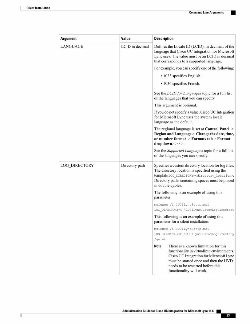
DescriptionValueArgument
Defines the Locale ID (LCID), in decimal, of thelanguage that Cisco UC Integration for MicrosoftLync uses. The value must be an LCID in decimalthat corresponds to a supported language.
For example, you can specify one of the following:
• 1033 specifies English.
• 1036 specifies French.
See the LCID for Languages topic for a full listof the languages that you can specify.
This argument is optional.
If you do not specify a value, Cisco UC Integrationfor Microsoft Lync uses the system localelanguage as the default.
The regional language is set at Control Panel >Region and Language > Change the date, time,or number format > Formats tab > Formatdropdown> >> > .
See the Supported Languages topic for a full listof the languages you can specify.
LCID in decimalLANGUAGE
Specifies a custom directory location for log files.The directory location is specified using thetemplate LOG_DIRECTORY=<directory_location>.Directory paths containing spaces must be placedin double quotes.
The following is an example of using thisparameter:
msiexec /i CUCILyncSetup.msi
LOG_DIRECTORY=C:\CUCILyncCustomLogDirectory
This following is an example of using thisparameter for a silent installation:
msiexec /i CUCILyncSetup.msi
LOG_DIRECTORY=C:\CUCILyncCustomLogDirectory
/quiet
There is a known limitation for thisfunctionality in virtualized environments.Cisco UC Integration for Microsoft Lyncmust be started once and then the HVDneeds to be restarted before thisfunctionality will work.
Note
Directory pathLOG_DIRECTORY
Administration Guide for Cisco UC Integration for Microsoft Lync 11.6 83
Client InstallationCommand Line Arguments

DescriptionValueArgument
Specifies the URL to which users are directed ifthey forget, or need to reset, their passwords.
This argument is optional but recommended.
URLFORGOT_PASSWORD_URL
Specifies whether the Sign me in when clientstarts check box is checked when the user installsthe client.
• true—The Sign me in when client startscheck box is checked when the user installsthe client.
• false (default)— The Sign me in whenclient starts check box is not checked whenthe user installs the client.
true
false
AUTOMATIC_SIGN_IN
Specifies whether analytics data is gathered. Thedefault value is true.
To improve your experience and productperformance, Cisco UC Integration for MicrosoftLync may collect and send non-personallyidentifiable usage and performance data to Cisco.The aggregated data is used by Cisco tounderstand trends in how clients are being usedand how they are performing.
Full details on what analytics data Cisco UCIntegration for Microsoft Lync does and does notcollect can be found in the Cisco UC IntegrationforMicrosoft Lync Supplement to Cisco's On-LinePrivacy Policy at http://www.cisco.com/web/siteassets/legal/privacy.html
true
false
TELEMETRY_ENABLED
Specifies a unique name for the globalconfiguration file on your TFTP server. Youshould specify a value for this argument if yourglobal configuration file does not use the defaultname of jabber-config.xml.
You can specify either an unqualified or fullyqualified filename as the value. The name youspecify as the value for this argument overridesany other global configuration files on your TFTPserver.
This argument is optional.
FilenameTFTP_FILE_NAME
Specifies the domain name used to resolve thecontacts on the active directory. For exampledomain.com.
Domain nameused
PRESENCE_DOMAIN
Administration Guide for Cisco UC Integration for Microsoft Lync 11.684
Client InstallationCommand Line Arguments

DescriptionValueArgument
Specifies if voicemail is enabled.
• true (default)—Enables voicemail.
• false—Disables voicemail.
true
false
VOICEMAIL_ENABLED
Specifies if Cisco UC Integration for MicrosoftLync overrides any existing bootstrap file fromprevious installations.
Cisco UC Integration for Microsoft Lync savesthe arguments and values you set duringinstallation to the bootstrap file,jabber-bootstrap.properties. CiscoUC Integration for Microsoft Lync then loadssettings from the bootstrap file at startup.
Specify this argument
If you specify this argument, the followingoccurs during installation:
1 Cisco UC Integration for MicrosoftLync deletes any existing bootstrap file.
2 Cisco UC Integration for MicrosoftLync creates a new bootstrap file.
Do not specify this argument
If you do not specify this argument, CiscoUC Integration for Microsoft Lync checksfor existing bootstrap files duringinstallation.
• If no bootstrap file exists, Cisco UCIntegration forMicrosoft Lync createsa bootstrap file during installation.
• If a bootstrap file exists, Cisco UCIntegration for Microsoft Lync doesnot override that bootstrap file andpreserves the existing settings.
1CLEAR
Administration Guide for Cisco UC Integration for Microsoft Lync 11.6 85
Client InstallationCommand Line Arguments

DescriptionValueArgument
If you are reinstalling Cisco UCIntegration for Microsoft Lync, youshould consider the following:
Note
• Cisco UC Integration for MicrosoftLync does not preserve settingsfrom existing bootstrap files. If youspecify CLEAR, you must alsospecify all other installationarguments as appropriate.
• Cisco UC Integration for MicrosoftLync does not save your installationarguments to an existing bootstrapfile. If you want to change thevalues for installation arguments, orspecify additional installationarguments, you must specifyCLEAR to override the existingsettings.
To override existing bootstrap files, specifyCLEAR in the command line as follows:msiexec.exe /i CUCILyncSetup.msi CLEAR=1
• true (default)—The Report a problem menuitem is enabled in the Help menu in theclient.
• false—The Report a problem menu item isremoved from in the Helpmenu in the client.
If you set the argument to false, users can stillmanually use the Start Menu > Cisco UCIntegration for Microsoft Lync directory, or theProgram files directory and launch the ProblemReport Tool manually. If a user manually createsa PRT, and this parameter value is set to false,then the zip file created from the PRT has nocontent.
true
false
ENABLE_PRT
Administration Guide for Cisco UC Integration for Microsoft Lync 11.686
Client InstallationCommand Line Arguments

DescriptionValueArgument
Enables problem report encryption. You mustconfigure this argument with thePRT_CERTIFICATE_NAME argument.
• true—PRT files sent by the client areencrypted.
• false(default)—PRT files sent by the clientare not encrypted.
PRT encryption requires a public/private key pairto encrypt and decrypt the problem report.
true
false
ENABLE_PRT_ENCRYPTION
Specifies the name of a certificate with a publickey in the Enterprise Trust or Trusted RootCertificate Authorities certificate store. Thecertificate public key is used to encrypt Problemreports. You must configure this argument withthe ENABLE_PRT_ENCRYPTION argument.
Certificate namePRT_CERTIFICATE_NAME
Specifies the client behavior for invalidcertificates.
• RejectAndNotify—A warning dialogdisplays and the client doesn't load.
• PromptPerSession—A warning dialogdisplays and the user can accept or reject theinvalid certificate.
RejectAndNotify
PromptPerSession
INVALID_CERTIFICATE_BEHAVIOR
Enables DPI awareness.
• true (default)—DPI awareness is enabled.
• false—DPI awareness is not enabled.
true
false
ENABLE_DPI_AWARE
Specifies the network IP protocol for the client.
• IPV4_Only—The client will only attemptto make IPv4 connections.
• IPV6_Only—The client will only attemptto make IPv6 connections.
• Dual_Stack (Default)—The client canconnect with either IPv4 or IPv6.
There are a number of factors used to determinethe network IP protocol used by client, for moreinformation see the IPv6 Requirements sectionin this guide.
IPV4_Only
IPV6_Only
Dual_Stack
IP_MODE
Administration Guide for Cisco UC Integration for Microsoft Lync 11.6 87
Client InstallationCommand Line Arguments

DescriptionValueArgument
Specifies whether the Diagnostics Tool is availableto users.
• true (default)—Users can display thediagnostics tool by entering CTRL +SHIFT+D.
• false—Diagnostics tool is not available tousers.
true
false
DIAGNOSTICS_TOOL_ENABLED
LCID for LanguagesThe following table lists the Locale Identifier (LCID) or Language Identifier (LangID) for the languages thatthe Cisco Jabber clients support.
LCID/LangIDSupported Languages
1025Arabic - Saudi Arabia
1026Bulgarian - Bulgaria
1027Catalan - Spain
2052Chinese (Simplified) - China
1028Chinese (Traditional) - Taiwan
1050Croatian - Croatia
1029Czech - Czech Republic
1030Danish - Denmark
1043Dutch - Netherlands
1033English - United States
1035Finnish - Finland
1036French - France
1031German - Germany
1032Greek - Greece
1037Hebrew - Israel
Administration Guide for Cisco UC Integration for Microsoft Lync 11.688
Client InstallationLCID for Languages
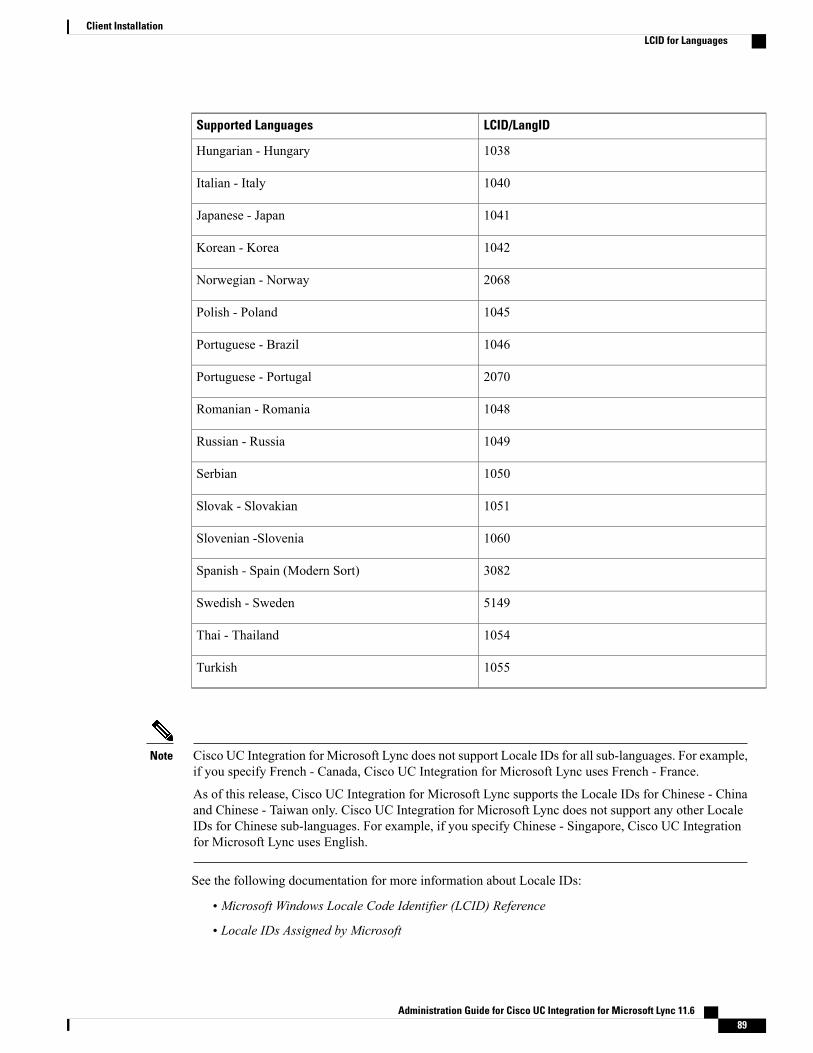
LCID/LangIDSupported Languages
1038Hungarian - Hungary
1040Italian - Italy
1041Japanese - Japan
1042Korean - Korea
2068Norwegian - Norway
1045Polish - Poland
1046Portuguese - Brazil
2070Portuguese - Portugal
1048Romanian - Romania
1049Russian - Russia
1050Serbian
1051Slovak - Slovakian
1060Slovenian -Slovenia
3082Spanish - Spain (Modern Sort)
5149Swedish - Sweden
1054Thai - Thailand
1055Turkish
Cisco UC Integration for Microsoft Lync does not support Locale IDs for all sub-languages. For example,if you specify French - Canada, Cisco UC Integration for Microsoft Lync uses French - France.
As of this release, Cisco UC Integration for Microsoft Lync supports the Locale IDs for Chinese - Chinaand Chinese - Taiwan only. Cisco UC Integration for Microsoft Lync does not support any other LocaleIDs for Chinese sub-languages. For example, if you specify Chinese - Singapore, Cisco UC Integrationfor Microsoft Lync uses English.
Note
See the following documentation for more information about Locale IDs:
• Microsoft Windows Locale Code Identifier (LCID) Reference
• Locale IDs Assigned by Microsoft
Administration Guide for Cisco UC Integration for Microsoft Lync 11.6 89
Client InstallationLCID for Languages
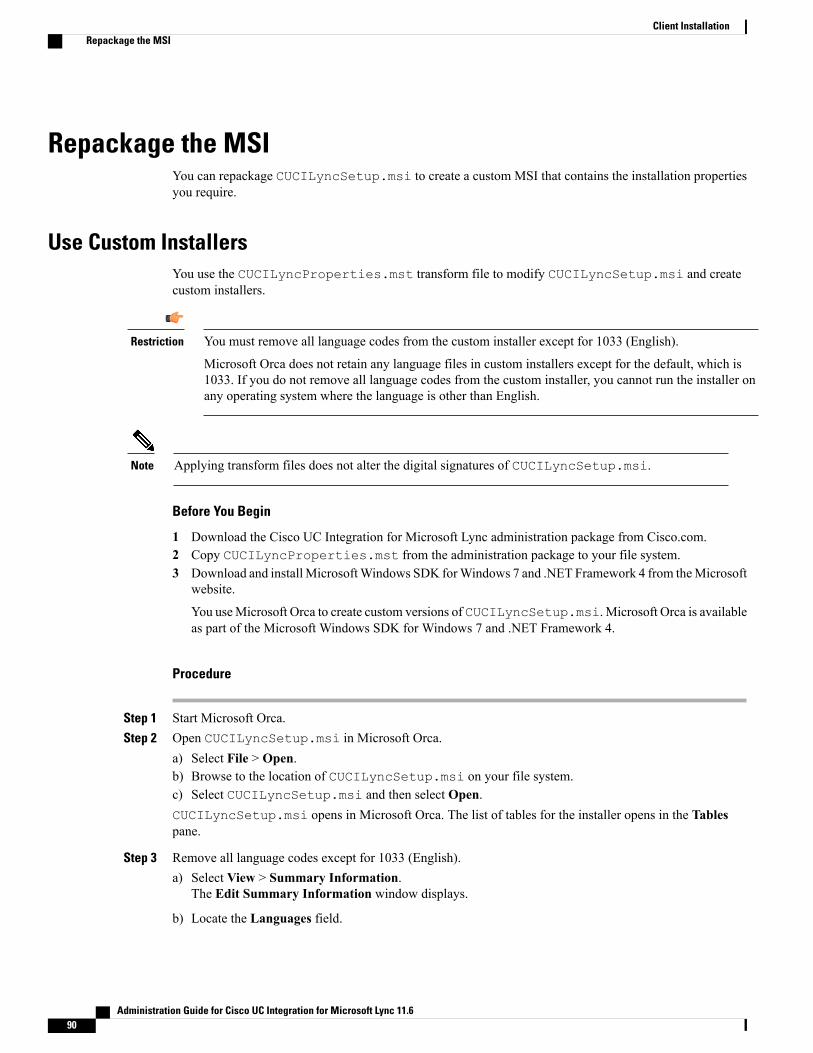
Repackage the MSIYou can repackage CUCILyncSetup.msi to create a custom MSI that contains the installation propertiesyou require.
Use Custom InstallersYou use the CUCILyncProperties.mst transform file to modify CUCILyncSetup.msi and createcustom installers.
You must remove all language codes from the custom installer except for 1033 (English).
Microsoft Orca does not retain any language files in custom installers except for the default, which is1033. If you do not remove all language codes from the custom installer, you cannot run the installer onany operating system where the language is other than English.
Restriction
Applying transform files does not alter the digital signatures of CUCILyncSetup.msi.Note
Before You Begin
1 Download the Cisco UC Integration for Microsoft Lync administration package from Cisco.com.2 Copy CUCILyncProperties.mst from the administration package to your file system.3 Download and installMicrosoftWindows SDK forWindows 7 and .NET Framework 4 from theMicrosoft
website.
You useMicrosoft Orca to create custom versions of CUCILyncSetup.msi. Microsoft Orca is availableas part of the Microsoft Windows SDK for Windows 7 and .NET Framework 4.
Procedure
Step 1 Start Microsoft Orca.Step 2 Open CUCILyncSetup.msi in Microsoft Orca.
a) Select File > Open.b) Browse to the location of CUCILyncSetup.msi on your file system.c) Select CUCILyncSetup.msi and then select Open.CUCILyncSetup.msi opens in Microsoft Orca. The list of tables for the installer opens in the Tablespane.
Step 3 Remove all language codes except for 1033 (English).a) Select View > Summary Information.
The Edit Summary Information window displays.
b) Locate the Languages field.
Administration Guide for Cisco UC Integration for Microsoft Lync 11.690
Client InstallationRepackage the MSI
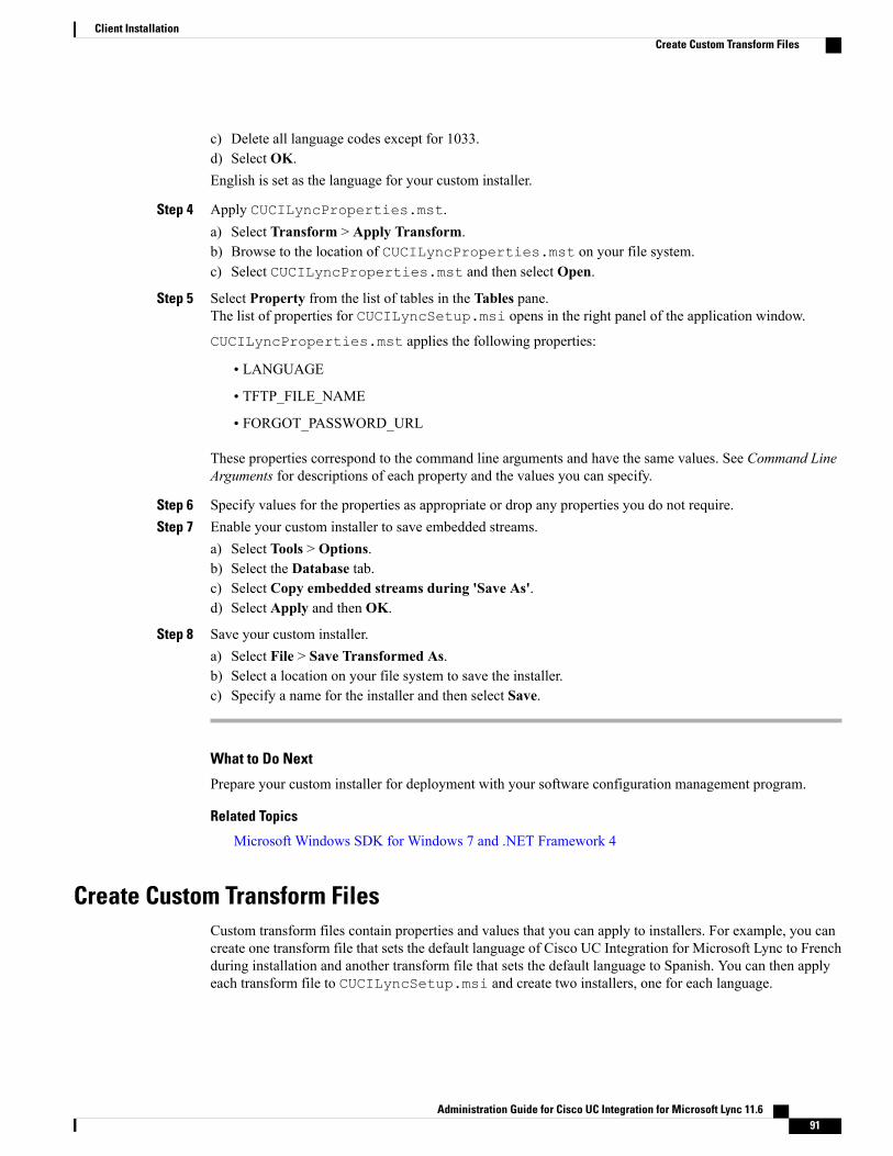
c) Delete all language codes except for 1033.d) Select OK.English is set as the language for your custom installer.
Step 4 Apply CUCILyncProperties.mst.a) Select Transform > Apply Transform.b) Browse to the location of CUCILyncProperties.mst on your file system.c) Select CUCILyncProperties.mst and then select Open.
Step 5 Select Property from the list of tables in the Tables pane.The list of properties for CUCILyncSetup.msi opens in the right panel of the application window.
CUCILyncProperties.mst applies the following properties:
• LANGUAGE
• TFTP_FILE_NAME
• FORGOT_PASSWORD_URL
These properties correspond to the command line arguments and have the same values. See Command LineArguments for descriptions of each property and the values you can specify.
Step 6 Specify values for the properties as appropriate or drop any properties you do not require.Step 7 Enable your custom installer to save embedded streams.
a) Select Tools > Options.b) Select the Database tab.c) Select Copy embedded streams during 'Save As'.d) Select Apply and then OK.
Step 8 Save your custom installer.a) Select File > Save Transformed As.b) Select a location on your file system to save the installer.c) Specify a name for the installer and then select Save.
What to Do Next
Prepare your custom installer for deployment with your software configuration management program.
Related Topics
Microsoft Windows SDK for Windows 7 and .NET Framework 4
Create Custom Transform FilesCustom transform files contain properties and values that you can apply to installers. For example, you cancreate one transform file that sets the default language of Cisco UC Integration for Microsoft Lync to Frenchduring installation and another transform file that sets the default language to Spanish. You can then applyeach transform file to CUCILyncSetup.msi and create two installers, one for each language.
Administration Guide for Cisco UC Integration for Microsoft Lync 11.6 91
Client InstallationCreate Custom Transform Files
Procedure
Step 1 Start Microsoft Orca.Step 2 Open CUCILyncSetup.msi and then apply CUCILyncProperties.mst.
See Transform the Installer for more information.
Step 3 Specify values for the appropriate installer properties.Step 4 Generate and save the transform file.
a) Select Transform > Generate Transform.b) Select a location on your file system to save the transform file.c) Specify a name for the transform file and select Save.
The transform file you created is saved as file_name.mst. You can apply this transform file to modifythe properties of CUCILyncSetup.msi.
Deploy with Group PolicyInstall Cisco UC Integration for Microsoft Lync with Group Policy using the Microsoft Group PolicyManagement Console (GPMC) on Microsoft Windows Server.
To install Cisco UC Integration for Microsoft Lync with Group Policy, all computers or users to whichyou plan to deploy Cisco UC Integration for Microsoft Lync must be in the same domain.
Note
Before You Begin
Complete the following steps to set a language code in the installation package:
1 Start Microsoft Orca.
Microsoft Orca is available as part of the Microsoft Windows SDK for Windows 7 and .NET Framework4 that you can download from the Microsoft website.
2 Open CUCILyncSetup.msi.
a Select File > Open.
b Browse to the location of CUCILyncSetup.msi on your file system.
c Select CUCILyncSetup.msi and then select Open.
3 Select View > Summary Information.
4 Locate the Languages field.
5 Set the Locale ID that corresponds to the installation language.
For example, set 1033 as the Locale ID to specify English as the installation language.
6 Select OK.
Administration Guide for Cisco UC Integration for Microsoft Lync 11.692
Client InstallationDeploy with Group Policy

7 Save the installation package.
You must enable embedded streams if you select File > Save As to save the installation package.
1 Select Tools > Options and then select the Database tab.
2 Select Copy embedded streams during 'Save As'.
3 Select Apply and then OK.
Procedure
Step 1 Copy the installation package to a software distribution point for deployment.All computers or users to which you plan to deploy Cisco UC Integration for Microsoft Lync must be able toaccess the installation package on the distribution point.
Step 2 Select Start > Run and then enter the following command:GPMC.msc
The Group Policy Management console opens.
Step 3 Create a new group policy object.a) Right-click on the appropriate domain in the left pane.b) Select Create a GPO in this Domain, and Link it here.
The New GPO window opens.
c) Enter a name for the group policy object in the Name field.d) Leave the default value or select an appropriate option from the Source Starter GPO drop-down list and
then select OK.The new group policy displays in the list of group policies for the domain.
Step 4 Set the scope of your deployment.a) Select the group policy object under the domain in the left pane.
The group policy object displays in the right pane.
b) Select Add in the Security Filtering section of the Scope tab.The Select User, Computer, or Group window opens.
c) Specify the computers and users to which you want to deploy Cisco UC Integration for Microsoft Lync.
Step 5 Specify the installation package.a) Right-click the group policy object in the left pane and then select Edit.
The Group Policy Management Editor opens.
b) Select Computer Configuration and then select Policies > Software Settings.c) Right-click Software Installation and then select New > Package.d) Enter the location of the installation package next to File Name; for example,
\\server\software_distribution.You must enter a Uniform Naming Convention (UNC) path as the location of the installationpackage. If you do not enter a UNC path, Group Policy cannot deploy Cisco UC Integrationfor Microsoft Lync.
Important
e) Select the installation package and then select Open.
Administration Guide for Cisco UC Integration for Microsoft Lync 11.6 93
Client InstallationDeploy with Group Policy
f) In the Deploy Software dialog box, select Assigned and then OK.
Group Policy installs Cisco UC Integration for Microsoft Lync on each computer the next time each computerstarts.
Presence Status
On the Phone PresenceCisco UC Integration for Microsoft Lync includes the custom presence status of On the Phone. This statusis stored in the custompresence.xml file. This file is installed with the application. The default location forthis file is C:\Program Files (x86)\Cisco Systems\CUCILync\custompresence.xml.
Procedure
Microsoft Lync 2010 can't use this file by default because the registry key which defines the location of thecustom presence file is ignored byMicrosoft Lync 2010 unless it begins with https://. Therefore, administratorshave two options for deploying the custom presence file:
• Deploy the custompresence.xml file to a secure web server such as the instance of Microsoft InternetInformation Services that runs on the Microsoft Lync Server and update the following registry valuewith this location for all Lync users:
• HKEY_LOCAL_MACHINE\SOFTWARE\Policies\Microsoft\Communicator\CustomStateURL forMicrosoft Lync 2010
• HKEY_LOCAL_MACHINE\SOFTWARE\Policies\Microsoft\Office\15.0\Lync\CustomStateURL forMicrosoft Lync 2013
See these Microsoft sites for more information:
• http://www.microsoft.com/DOWNLOADS/details.aspx?familyid=5D6F4B90-6980-430B-9F97-FFADBC07B7A9&displaylang=en
• http://www.microsoft.com/downloads/details.aspx?FamilyID=dd3cae08-3153-4c6a-a314-daa79d616248&displaylang=en
• Administrators can use the custompresence.xml file installed on the local machine if they currently arenot using the Lync SIP High Security Mode or use of the Lync SIP High Security Mode is not necessary.
Lync SIP High Security Mode is disabled in the Windows Registry by setting theEnableSIPHighSecurityMode value to zero (0). This value is located in the following locations:
• HKEY_LOCAL_MACHINE\SOFTWARE\Policies\Microsoft\Communicator for Microsoft Lync 2010
• HKEY_LOCAL_MACHINE\SOFTWARE\Policies\Microsoft\Office\15.0\Lync for Microsoft Lync2013
Administration Guide for Cisco UC Integration for Microsoft Lync 11.694
Client InstallationPresence Status
Appear Offline PresenceCisco UC Integration for Microsoft Lync includes the presence status of Appear Offline.
When a user setsAppear Offline as their presence status in Microsoft Lync or Skype for Business and makesa call with Cisco UC Integration for Microsoft Lync, the presence in Microsoft Lync or Skype for Businesswill remain Offline
When a user setsAppear Offline as their presence status in Microsoft Lync or Skype for Business and makesa call with Cisco UC Integration for Microsoft Lync and during Cisco UC Integration for Microsoft Lync calluser sets Microsoft Lync or Skype for Business presence status to Available it will be automatically changedto On The Phone if configured, if not status will be Busy.
When a user changes their Microsoft Lync or Skype for Business presence status to Appear Offline duringa Cisco UC Integration for Microsoft Lync call, it will remain Offline after call ends.
Procedure
To enable the Appear Offline presence status, add the "EnableAppearOffline"=dword:00000001 registryentry to the registry locations for your Office version:
• HKEY_LOCAL_MACHINE\SOFTWARE\Policies\Microsoft\Office\14.0\Lync for Microsoft Lync 2010
• HKEY_LOCAL_MACHINE\SOFTWARE\Policies\Microsoft\Office\15.0\Lync for Microsoft Lync 2013
• HKEY_LOCAL_MACHINE\SOFTWARE\Policies\Microsoft\Office\16.0\Lync for Microsoft Lync 2016
Cisco Media Services InterfaceCisco Media Services Interface provides a Microsoft Windows service that works with Cisco PrimeCollaboration Manager and Cisco Medianet-enabled routers. Cisco UC Integration for Microsoft Lync sendsaudio media and video media on your network with minimum latency or packet loss.
Traffic Marking
For each audio call or video call, Cisco UC Integration for Microsoft Lync checks for Cisco Media ServicesInterface before sending audio media or video media.
• If the service exists on the computer—CiscoUC Integration forMicrosoft Lync provides flow informationto Cisco Media Services Interface.
The service then signals the network so that routers classify the flow and provide priority to the CiscoUC Integration for Microsoft Lync traffic.
• If the service does not exist—Cisco UC Integration for Microsoft Lync does not use it and sends audiomedia and video media as normal.
Desk Phone Video Capabilities
To enable desk phone video capabilities, install CiscoMedia Services Interface. CiscoMedia Services Interfaceprovides a driver that enables Cisco UC Integration for Microsoft Lync to do the following:
• Discover the desk phone device.
Administration Guide for Cisco UC Integration for Microsoft Lync 11.6 95
Client InstallationAppear Offline Presence

• Establish and maintain a connection to the desk phone device using the CAST protocol.
Before You Begin
Cisco UC Integration for Microsoft Lync supports Cisco Media Services Interface version 3.2.2 or later.
• Install Cisco Prime Collaboration Manager.
• Install routers or switches enabled for Cisco Medianet where appropriate.
• Configure your network to handle the metadata attributes that Cisco Media Services Interface appliesto applications.
Not all devices on your network must support Cisco Medianet. The first hop prioritizes traffic based onthe metadata attributes from Cisco Media Services Interface. As the traffic traverses the network, allother devices also prioritize that traffic unless you configure policies on those devices to handle thetraffic differently. See the Medianet Knowledge Base Portal for detailed information on configuringyour network.
Procedure
Step 1 Download the Cisco Media Services Interface installation program from the Cisco UC Integration forMicrosoft Lync download site on Cisco.com.
Step 2 Install Cisco Media Services Interface on each computer on which you install Cisco UC Integration forMicrosoft Lync.See the appropriate Cisco Medianet documentation for installing Cisco Media Services Interface.
Uninstall Cisco UC Integration for Microsoft LyncYou can uninstall Cisco UC Integration for Microsoft Lync using either the command line or the MicrosoftWindows control panel. This topic describes how to uninstall Cisco UC Integration for Microsoft Lync usingthe command line.
To uninstall Cisco UC Integration for Microsoft Lync with the command line, you can use the MSI or theproduct code. You should use the MSI if it is available on the file system. However, if the MSI is not availableon the file system, you should use the product code.
Procedure
Step 1 Open a command line window.Step 2 Enter one of the following commands to uninstall Cisco UC Integration for Microsoft Lync:
Administration Guide for Cisco UC Integration for Microsoft Lync 11.696
Client InstallationUninstall Cisco UC Integration for Microsoft Lync
CommandOption
msiexec.exe /x path_to_CUCILyncSetup.msiThe following is an example command to uninstall Cisco UC Integration for MicrosoftLync with the MSI:msiexec.exe /x C:\Windows\Installer\CUCILyncSetup.msi /quietWhere /quiet specifies a silent uninstall.
Uninstall with theMSI
msiexec.exe /x product_codeThe following is an example command to uninstall Cisco UC Integration for MicrosoftLync with the product code:msiexec.exe /x 45992224-D2DE-49BB-B085-6524845321C7 /quietWhere /quiet specifies a silent uninstall.
To find the product code for Cisco UC Integration forMicrosoft Lync, do the following:
1 Open the Microsoft Windows registry editor.2 Locate the following registry key:HKEY_CLASSES_ROOT\Installer\Products3 Select Edit > Find.4 Enter Cisco UC Integration for Microsoft Lync in the Find what text box in the
Find window and select Find Next.5 Locate the ProductIcon registry key.
The product code is specified in the value data of the ProductIcon registry key asfollows:C:\Windows\Installer\{product_code}\ARPPRODUCTICON.exe.
The product code changes with each version of Cisco UC Integration forMicrosoft Lync.
Note
Uninstall with theproduct code
The command removes Cisco UC Integration for Microsoft Lync from the computer.
Administration Guide for Cisco UC Integration for Microsoft Lync 11.6 97
Client InstallationUninstall Cisco UC Integration for Microsoft Lync

Administration Guide for Cisco UC Integration for Microsoft Lync 11.698
Client InstallationUninstall Cisco UC Integration for Microsoft Lync
C H A P T E R 8Configuration
Cisco UC Integration for Microsoft Lync retrieves configuration settings from XML files that reside on yourTFTP server. This section helps you to understand when you should create a custom configuration and learnabout the different types of configuration files you can create.
• Global Configuration Files, page 99
• Group Configuration Files, page 99
• Configuration File Requirements, page 101
Global Configuration FilesGlobal configuration files apply to all Cisco UC Integration for Microsoft Lync users. Cisco UC Integrationfor Microsoft Lync downloads the global configuration file from your TFTP server during the login sequence.
Global Configuration File Names
The default name for the global configuration file is jabber-config.xml. However, you can specify aunique name for the global configuration file during deployment using the following command line argument:
TFTP_FILE_NAME
See the installation chapter for more information about the command line arguments.
Group Configuration FilesGroup configuration files apply to subsets of Cisco UC Integration for Microsoft Lync users. Groupconfiguration files take priority over global configuration files.
Cisco UC Integration for Microsoft Lync retrieves group configuration files after users sign in to their phoneaccount in the client for the first time. Cisco UC Integration for Microsoft Lync then prompts the users to signout. During the second login sequence, Cisco UC Integration for Microsoft Lync downloads the groupconfiguration file from your TFTP server.
Cisco UC Integration for Microsoft Lync loads group configuration files as follows:
Administration Guide for Cisco UC Integration for Microsoft Lync 11.6 99

Users are not signed in
1 Users sign in.
2 Users sign out.
3 Users sign in and then Cisco UC Integration for Microsoft Lync loads the group configurationsettings.
Users are signed in and use software phones for calls
1 Users are signed in and using their software phones for calls.
2 Users sign out.
3 Users sign in and then Cisco UC Integration for Microsoft Lync loads the group configurationsettings.
Users are signed in and use desk phones for calls
1 Users are signed in and using their desk phones for calls.
2 Users sign out.
3 Users sign in and then Cisco UC Integration for Microsoft Lync loads the group configurationsettings.
If users select the option to use software phones for calls before they sign out, Cisco UC Integrationfor Microsoft Lync notifies the users to sign out and then sign in again to load the group configurationsettings.
Group Configuration File Names
You specify the name of the group configuration files in the Cisco Support Field on the CSF deviceconfiguration in Cisco Unified Communications Manager.
If you remove the name of the group configuration file in the CSF device configuration on Cisco UnifiedCommunications Manager, Cisco UC Integration for Microsoft Lync detects the change, prompts the usersto sign out, and loads the global configuration file. You can remove the name of the group configuration filein the CSF device configuration by deleting the entireconfigurationFile=group_configuration_file_name.xml string or by deleting the groupconfiguration filename from the string.
If users have desk phone devices only, use the following command line argument to specify unique namesconfiguration files for different groups:
TFTP_FILE_NAME
See the Installation chapter for more information about the command line arguments.
Administration Guide for Cisco UC Integration for Microsoft Lync 11.6100
ConfigurationGroup Configuration Files

Configuration File Requirements• Configuration filenames are case sensitive. Use lowercase letters in the filename to prevent errors andto ensure Cisco UC Integration for Microsoft Lync can retrieve the file from the TFTP server.
• You must use utf-8 encoding for the configuration files.
• Cisco UC Integration for Microsoft Lync cannot read configuration files that do not have a valid XMLstructure. Ensure you check the structure of your configuration file for closing elements and that elementsare nested correctly. Review the examples of configuration files in this chapter for more information.
• Your XML can contain only valid XML character entity references. For example, use & insteadof &. If your XML contains invalid characters, Cisco UC Integration for Microsoft Lync cannot parsethe configuration file.Open your configuration file in Microsoft Internet Explorer to determine if any characters or entities arenot valid. If Internet Explorer displays the entire XML structure, your configuration file does not containinvalid characters or entities. If Internet Explorer displays only part of the XML structure, yourconfiguration file most likely contains invalid characters or entities.
Administration Guide for Cisco UC Integration for Microsoft Lync 11.6 101
ConfigurationConfiguration File Requirements

Administration Guide for Cisco UC Integration for Microsoft Lync 11.6102
ConfigurationConfiguration File Requirements

C H A P T E R 9Deployment Configuration
• Create Group Configurations, page 103
• Create Global Configurations, page 105
• Restart Your TFTP Server, page 105
• Configuration File Structure, page 106
• Client Parameters, page 107
• Directory Attribute Mapping Parameters, page 111
• Directory Connection Parameters, page 112
• Directory Query Parameters, page 114
• Contact Photo Retrieval, page 119
• Contact Resolution, page 122
• Phone Parameters, page 123
• Policy Parameters, page 125
• Voicemail Parameters, page 129
• Internet Explorer Pop-up Parameters, page 130
• Configure Automatic Updates, page 132
• Configure Problem Reporting, page 133
• Custom Embedded Tabs, page 135
• Configuration File Example, page 140
• Registry Key Configuration, page 140
Create Group ConfigurationsCisco UC Integration forMicrosoft Lync retrieves the names of group configuration files from the CSF deviceconfiguration on Cisco Unified Communications Manager.
Administration Guide for Cisco UC Integration for Microsoft Lync 11.6 103

If you do not configure CSF devices for users, you cannot apply group configurations to those users.Restriction
Procedure
Step 1 Create an XML group configuration file with any text editor.The group configuration file can have any appropriate name; for example,cucilync-groupa-config.xml.
• Use lowercase letters in the filename.
• Use utf-8 encoding.
Step 2 Define the required configuration parameters in the group configuration file.If the structure of your configuration file is not valid, Cisco UC Integration for Microsoft Lynccannot read the settings you define. See the sample XML in this chapter for an example of thestructure your configuration file must have.
Important
Step 3 Host the group configuration file on your TFTP server.a) Open the Cisco Unified OS Administration interface.b) Select Software Upgrades > TFTP File Management.c) Select Upload File.d) Select Browse in the Upload File section.e) Select the group configuration file on the file system.f) Do not specify a value in the Directory text box in the Upload File section.
If you specify a value for the Directory text box, make a note of the value. You must specify the path andfilename when you specify the group configuration file in the CSF device configuration on Cisco UnifiedCommunications Manager.
g) Select Upload File.
Step 4 Specify the name of the group configuration file in the Cisco Support Field field.Use the Bulk Administration Tool for multipleusers.
Timesaver
a) Open the Cisco Unified CM Administration interface.b) Select Device > Phone.c) Find and select the appropriate CSF device to which the group configuration applies.d) Locate the Product Specific Configuration Layout section of the Phone Configuration window.e) Locate the Desktop Client Settings section.f) Enter configurationfile=group_configuration_file_name.xml in the Cisco Support
Field field; for example, configurationfile=cucilync-groupa-config.xmlUse a semicolon to delimit multiple entries in the Cisco Support Field field. However, do notspecify multiple group configuration files. If you specify multiple group configuration files, CiscoUC Integration for Microsoft Lync uses the first group configuration available.
Note
If you host the group configuration file on your TFTP server in a location other than the default directory,you must specify the path and the filename in the Cisco Support Field field; for example,configurationfile=/customFolder/cucilync-groupa-config.xml.
g) Select Save.
Administration Guide for Cisco UC Integration for Microsoft Lync 11.6104
Deployment ConfigurationCreate Group Configurations
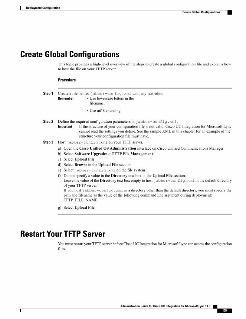
Create Global ConfigurationsThis topic provides a high-level overview of the steps to create a global configuration file and explains howto host the file on your TFTP server.
Procedure
Step 1 Create a file named jabber-config.xml with any text editor.Remember • Use lowercase letters in the
filename.
• Use utf-8 encoding.
Step 2 Define the required configuration parameters in jabber-config.xml.If the structure of your configuration file is not valid, Cisco UC Integration for Microsoft Lynccannot read the settings you define. See the sample XML in this chapter for an example of thestructure your configuration file must have.
Important
Step 3 Host jabber-config.xml on your TFTP server.a) Open the Cisco Unified OS Administration interface on Cisco Unified Communications Manager.b) Select Software Upgrades > TFTP File Management.c) Select Upload File.d) Select Browse in the Upload File section.e) Select jabber-config.xml on the file system.f) Do not specify a value in the Directory text box in the Upload File section.
Leave the value of the Directory text box empty to host jabber-config.xml in the default directoryof your TFTP server.If you host jabber-config.xml in a directory other than the default directory, you must specify thepath and filename as the value of the following command line argument during deployment:TFTP_FILE_NAME.
g) Select Upload File.
Restart Your TFTP ServerYoumust restart your TFTP server before Cisco UC Integration forMicrosoft Lync can access the configurationfiles.
Administration Guide for Cisco UC Integration for Microsoft Lync 11.6 105
Deployment ConfigurationCreate Global Configurations

Procedure
Step 1 Open the Cisco Unified Serviceability interface on Cisco Unified Communications Manager.Step 2 Select Tools > Control Center - Feature Services.Step 3 Select Cisco Tftp from the CM Services section.Step 4 Select Restart.
A window displays to prompt you to confirm the restart.
Step 5 Select OK.The Cisco Tftp Service Restart Operation was Successful status displays.
Step 6 Select Refresh to ensure the Cisco Tftp service starts successfully.
What to Do Next
To verify that the configuration file is available on your TFTP server, open the configuration file in anybrowser. Typically, you can access the global configuration file at the following URL:http://tftp_server_address:6970/jabber-config.xml
Configuration File StructureXML Structure
The following XML snippet shows the basic structure of a configuration file:<?xml version="1.0" encoding="utf-8"?><config version="1.0"><Client><parameter_name>value</parameter_name></Client><Directory><parameter_name>value</parameter_name></Directory><Options><parameter_name>value</parameter_name></Options><Phone><parameter_name>value</parameter_name></Phone><Policies><parameter_name>value</parameter_name></Policies><Voicemail><parameter_name>value</parameter_name></Voicemail></config>
The following table describes the elements in the basic structure of a configuration file:DescriptionElement
XML declaration. Your configuration file mustconform to the standard XML format.
<?xml version="1.0" encoding="utf-8"?>
Administration Guide for Cisco UC Integration for Microsoft Lync 11.6106
Deployment ConfigurationConfiguration File Structure

DescriptionElement
Root element of the configuration XML that containsthe available configuration groups. The root elementmust also contain the version attribute.
config
Parent element that contains client configurationparameters.
Client
Parent element that contains directory configurationparameters.
Directory
Parent element that contains user option configurationparameters for user options.
Options
Parent element that contains configuration parametersfor phone services.
Phone
Parent element that contains policy configurationparameters.
Policies
Parent element that contains voicemail configurationparameters.
Voicemail
Client ParametersDescriptionValueParameter
Specifies the custom script for submittingproblem reports.
For more information about problem reports, seeConfigure Problem Reporting
URLPrtLogServerUrl
Contains plug-in configuration elements.
You can define custom embedded tabs to displayHTML content in Cisco UC Integration forMicrosoft Lync. For more information, seeCustom Embedded Tabs.
Plug-in definitionjabber-plugin-config
Administration Guide for Cisco UC Integration for Microsoft Lync 11.6 107
Deployment ConfigurationClient Parameters

DescriptionValueParameter
Specifies whether the ability to control far-endcameras is enabled in the client.
In calls that support far-end camera control(FECC), you can adjust the far-end camera togive you a better view during video calls. FECCis available to users if the endpoint that they arecalling supports it.
Limitations:
• FECC is only supported in point-to-pointcalls, but not in group calls or conferenceswhere multiple video connections areconnecting to the same bridge.
• FECC is only supported in Softphonemode.
Values:
• true (default)—Far-end camera control isenabled. The Far-End Camera Controlbutton is enabled on the call video window.
• false—Far-end camera control is disabled.The Far-End Camera Control button isdisabled on the call video window, even ifthe endpoint is capable of far-end cameracontrol.
Example: <EnableFecc>false</EnableFecc>
true
false
EnableFECC
Specifies if the Report a problem menu item isavailable in the Help menu in the client.
• true (default)—The Report a problemmenu item is available.
• false—The Report a problem menu itemis removed.
Example: <EnablePrt>false</EnablePrt>
If you disable this parameter, users can stillmanually launch the Problem Report Toolmanually.
If a user manually creates a PRT, and thisparameter value is set to false, then the zip filecreated from the PRT has no content.
true
false
EnablePrt
Administration Guide for Cisco UC Integration for Microsoft Lync 11.6108
Deployment ConfigurationClient Parameters

DescriptionValueParameter
Enables problem report encryption. Configurethis parameter with the PRTCertificateNameparameter.
• true (default)—PRT files sent by the clientare encrypted.
• false—PRT files sent by the client are notencrypted.
PRT encryption requires a public or private keypair to encrypt and decrypt the problem report.For more information, refer to the Decrypt theProblem Report section in this document.
Example:<EnablePrtEncryption>true</EnablePrtEncryption>
true
false
EnablePrtEncryption
Specifies the name of a certificate with a publickey in the Enterprise Trust or Trusted RootCertificate Authorities certificate store. Thecertificate public key is used to encrypt Problemreports. You must configure this parameter withthe EnablePrtEncryption parameter.
Example:<PrtCertificateName>Certificate_Name</PrtCertificateName>
PrtCertificateName
Specifies if users can create their own customembedded tabs.
• true (default)—Users can create customembedded tabs.
• false—Users cannot create customembedded tabs.
Example:<AllowUserCustomTabs>false</AllowUserCustomTabs>
true
false
AllowUserCustomTabs
Specifies if the client shows the bridge escalationoptions.
• true—Bridge escalations options are shownin the client.
• false(default)—No bridge escalationsoptions are shown in the client.
Example:<EnableBridgeConferencing>true</EnableBridgeConferencing>
true
false
EnableBridgeConferencing
Administration Guide for Cisco UC Integration for Microsoft Lync 11.6 109
Deployment ConfigurationClient Parameters
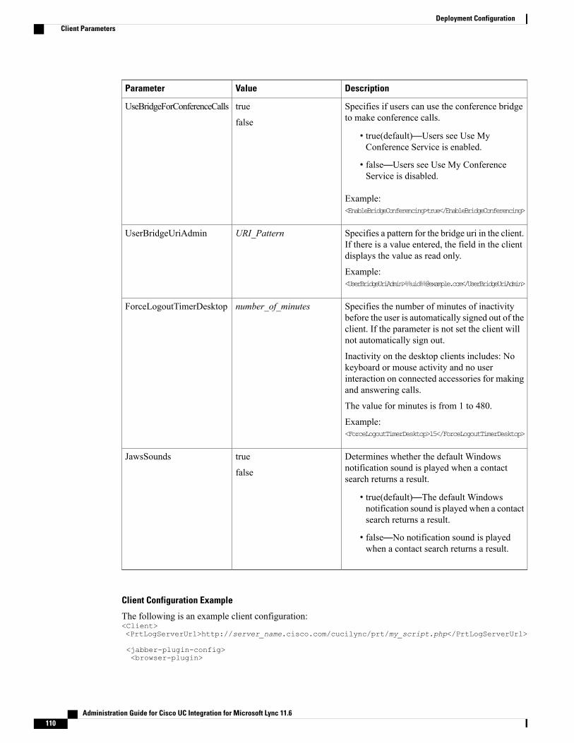
DescriptionValueParameter
Specifies if users can use the conference bridgeto make conference calls.
• true(default)—Users see Use MyConference Service is enabled.
• false—Users see Use My ConferenceService is disabled.
Example:<EnableBridgeConferencing>true</EnableBridgeConferencing>
true
false
UseBridgeForConferenceCalls
Specifies a pattern for the bridge uri in the client.If there is a value entered, the field in the clientdisplays the value as read only.
Example:<UserBridgeUriAdmin>%%uid%%@example.com</UserBridgeUriAdmin>
URI_PatternUserBridgeUriAdmin
Specifies the number of minutes of inactivitybefore the user is automatically signed out of theclient. If the parameter is not set the client willnot automatically sign out.
Inactivity on the desktop clients includes: Nokeyboard or mouse activity and no userinteraction on connected accessories for makingand answering calls.
The value for minutes is from 1 to 480.
Example:<ForceLogoutTimerDesktop>15</ForceLogoutTimerDesktop>
number_of_minutesForceLogoutTimerDesktop
Determines whether the default Windowsnotification sound is played when a contactsearch returns a result.
• true(default)—The default Windowsnotification sound is played when a contactsearch returns a result.
• false—No notification sound is playedwhen a contact search returns a result.
true
false
JawsSounds
Client Configuration Example
The following is an example client configuration:<Client><PrtLogServerUrl>http://server_name.cisco.com/cucilync/prt/my_script.php</PrtLogServerUrl>
<jabber-plugin-config><browser-plugin>
Administration Guide for Cisco UC Integration for Microsoft Lync 11.6110
Deployment ConfigurationClient Parameters

<page refresh="true" preload="true"><tooltip>Cisco</tooltip><icon>http://www.cisco.com/web/fw/i/logo.gif</icon><url>www.cisco.com</url></page></browser-plugin></jabber-plugin-config></Client>
Directory Attribute Mapping ParametersYou can change the default attribute mappings for Cisco UC Integration for Microsoft Lync. For example,by default, CiscoUC Integration forMicrosoft Lyncmaps the BusinessPhone parameter to the telephoneNumberattribute in your directory. The result of this mapping is that Cisco UC Integration forMicrosoft Lync retrievesthe value of the telephoneNumber attribute from your directory for a particular user. Cisco UC Integrationfor Microsoft Lync then displays this value as the user's work phone in that user's profile. If your organizationuses an attribute other than telephoneNumber for business phone numbers, you should change the mappingin the configuration file.
The following table describes the parameters for mapping directory attributes:Default ValueParameter
cnCommonName
displayNameDisplayName
givenNameFirstname
snLastname
mailEmailAddress
thumbnailPhotoPhotoSource
telephoneNumberBusinessPhone
mobileMobilePhone
homePhoneHomePhone
otherTelephoneOtherPhone
titleTitle
companyCompanyName
sAMAccountNameUserAccountName
userPrincipalNameDomainName
coLocation
nicknameNickname
postalCodePostalCode
lCity
stState
Administration Guide for Cisco UC Integration for Microsoft Lync 11.6 111
Deployment ConfigurationDirectory Attribute Mapping Parameters
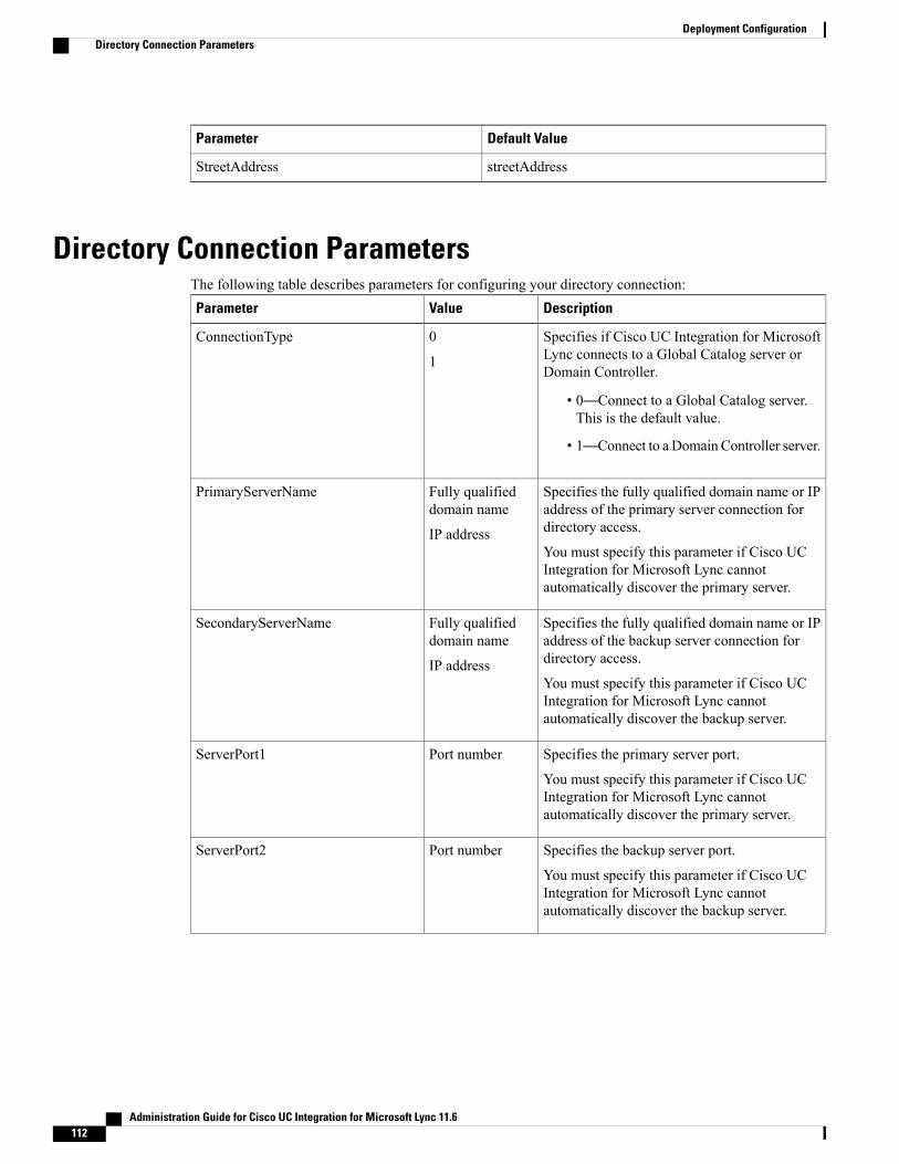
Default ValueParameter
streetAddressStreetAddress
Directory Connection ParametersThe following table describes parameters for configuring your directory connection:
DescriptionValueParameter
Specifies if Cisco UC Integration for MicrosoftLync connects to a Global Catalog server orDomain Controller.
• 0—Connect to a Global Catalog server.This is the default value.
• 1—Connect to a Domain Controller server.
0
1
ConnectionType
Specifies the fully qualified domain name or IPaddress of the primary server connection fordirectory access.
You must specify this parameter if Cisco UCIntegration for Microsoft Lync cannotautomatically discover the primary server.
Fully qualifieddomain name
IP address
PrimaryServerName
Specifies the fully qualified domain name or IPaddress of the backup server connection fordirectory access.
You must specify this parameter if Cisco UCIntegration for Microsoft Lync cannotautomatically discover the backup server.
Fully qualifieddomain name
IP address
SecondaryServerName
Specifies the primary server port.
You must specify this parameter if Cisco UCIntegration for Microsoft Lync cannotautomatically discover the primary server.
Port numberServerPort1
Specifies the backup server port.
You must specify this parameter if Cisco UCIntegration for Microsoft Lync cannotautomatically discover the backup server.
Port numberServerPort2
Administration Guide for Cisco UC Integration for Microsoft Lync 11.6112
Deployment ConfigurationDirectory Connection Parameters

DescriptionValueParameter
Specifies if Cisco UC Integration for MicrosoftLync uses Microsoft Windows credentials.
• 0—Use credentials you specify as thevalues for the ConnectionUsername andConnectionPassword parameters.
• 1—Use Microsoft Windows credentials.This is the default value.
0
1
UseWindowsCredentials
Specifies a username to connect to the directoryserver.
The client transmits and stores thisusername as plain text. Using thisparameter is not a secure methodof authenticating with the directoryserver.
Important
In most deployment scenarios, you do not needto specify a username to connect to the directoryserver.
This parameter enables you to authenticate witha directory server that requires a well-known orpublic set of credentials. You should include thisparameter in the client configuration only if itis not possible to authenticate with the directoryserver with the user's credentials.
UsernameConnectionUsername
Specifies a password to connect to the directoryserver.
The client transmits and stores thispassword as plain text. Using thisparameter is not a secure methodof authenticating with the directoryserver.
Important
In most deployment scenarios, you do not needto specify a password to connect to the directoryserver.
This parameter enables you to authenticate witha directory server that requires a well-known orpublic set of credentials. You should include thisparameter in the client configuration only if itis not possible to authenticate with the directoryserver with the user's credentials.
PasswordConnectionPassword
Administration Guide for Cisco UC Integration for Microsoft Lync 11.6 113
Deployment ConfigurationDirectory Connection Parameters

DescriptionValueParameter
Specifies if Cisco UC Integration for MicrosoftLync uses SSL for secure connections to thedirectory.
• 0—Disable SSL. This is the default value.
• 1—Enable SSL.
0
1
UseSSL
Specifies if Cisco UC Integration for MicrosoftLync uses simple authentication for theconnection to the directory service.
• 0—Use simple authentication. This is thedefault value.
• 1—Do not use simple authentication.
0
1
UseSecureConnection
Directory Query ParametersThe following table describes parameters for configuring howCisco UC Integration forMicrosoft Lync queriesyour directory:
DescriptionValueParameter
Specifies a base filter for Active Directoryqueries.
Specify a directory subkey name only to retrieveobjects other than user objects when you queryActive Directory.
The default value is(&(objectCategory=person).
Configuration files can contain only valid XMLcharacter entity references. Use & insteadof & if you specify a custom base filter.
In some cases, base filters do not return queryresults if you specify a closing bracket in yourCisco UC Integration for Microsoft Lyncconfiguration file. For example, this issue mightoccur if you specify the following base filter:(&(memberOf=CN=UCFilterGroup,OU=DN))
To resolve this issue, remove the closing bracket;for example,(&(memberOf=CN=UCFilterGroup,OU=DN)
Base filterBaseFilter
Administration Guide for Cisco UC Integration for Microsoft Lync 11.6114
Deployment ConfigurationDirectory Query Parameters

DescriptionValueParameter
Defines a filter to apply to predictive searchqueries.
The default value is anr=
When Cisco UC Integration for Microsoft Lyncperforms a predictive search, it issues a queryusingAmbiguousNameResolution (ANR). Thisquery disambiguates the search string and returnsresults that match the attributes that are set forANR on your directory server.
If you want Cisco UC Integrationfor Microsoft Lync to search forattributes that are not set for ANR,you must configure your directoryserver to set those attributes forANR.
Important
See the following Microsoft documentation formore information on ANR:
• Ambiguous Name Resolution for LDAP inWindows 2000
• LDAP Referrals, see the Ambiguous NameResolution section
• Common Default Attributes Set for ActiveDirectory and Global Catalog
Search filterPredictiveSearchFilter
Specifies whether users can search for alternativecontact numbers if the work number is notavailable, such as the mobile, home, or othernumber.
• 0—Users can search for alternative contactnumbers. This is the default value.
• 1—Users cannot search for alternativecontact numbers.
0
1
DisableSecondaryNumberLookups
Specifies masks to use when users search forphone numbers.
For example, a user receives a call from+14085550100. However, this number in ActiveDirectory is +(1) 408 555 0100. The followingmask ensures that the contact is found:+14081+(#) ### ### ####
The length of mask strings cannot exceed thesize restriction for registry subkey names.
Mask stringPhoneNumberMasks
Administration Guide for Cisco UC Integration for Microsoft Lync 11.6 115
Deployment ConfigurationDirectory Query Parameters

DescriptionValueParameter
Specifies the timeout period for queries inseconds.
The default value is 5.
Number ofseconds
SearchTimeout
Specifies whether to enable wildcard searches.
• 0—Do not use wildcards. This is thedefault value.
• 1—Use wildcards.
If you set 1 as the value, the speed ofsearches on the LDAP might be affected,especially if users search for directoryattributes that are not indexed.
You can use phone number masks instead ofwildcard searches.
0
1
UseWildcards
Specifies the minimum number of characters ina contact name needed to query the directory.
For example, if you set 2 as the value of thisparameter, directory lookups occur when usersenter at least two characters in the search field.
The default value is 3.
Numerical valueMinimumCharacterQuery
Administration Guide for Cisco UC Integration for Microsoft Lync 11.6116
Deployment ConfigurationDirectory Query Parameters
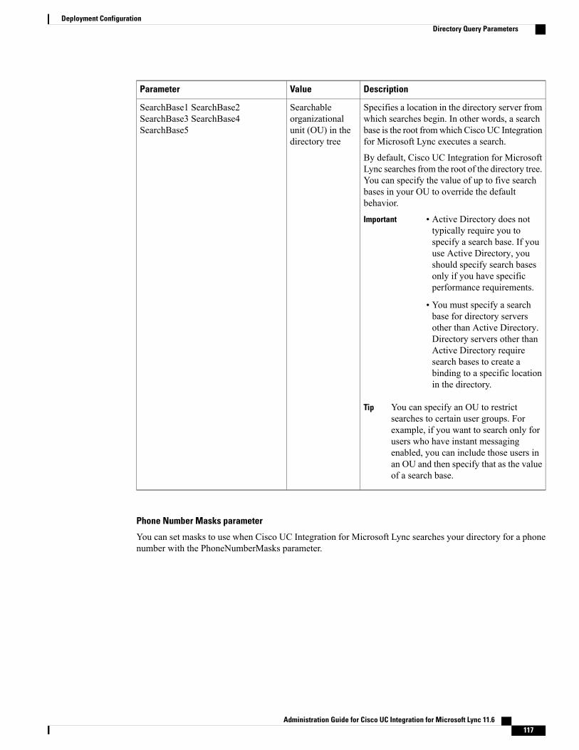
DescriptionValueParameter
Specifies a location in the directory server fromwhich searches begin. In other words, a searchbase is the root fromwhich Cisco UC Integrationfor Microsoft Lync executes a search.
By default, Cisco UC Integration for MicrosoftLync searches from the root of the directory tree.You can specify the value of up to five searchbases in your OU to override the defaultbehavior.
Important • Active Directory does nottypically require you tospecify a search base. If youuse Active Directory, youshould specify search basesonly if you have specificperformance requirements.
• You must specify a searchbase for directory serversother than Active Directory.Directory servers other thanActive Directory requiresearch bases to create abinding to a specific locationin the directory.
You can specify an OU to restrictsearches to certain user groups. Forexample, if you want to search only forusers who have instant messagingenabled, you can include those users inan OU and then specify that as the valueof a search base.
Tip
Searchableorganizationalunit (OU) in thedirectory tree
SearchBase1 SearchBase2SearchBase3 SearchBase4SearchBase5
Phone Number Masks parameter
You can set masks to use when Cisco UC Integration for Microsoft Lync searches your directory for a phonenumber with the PhoneNumberMasks parameter.
Administration Guide for Cisco UC Integration for Microsoft Lync 11.6 117
Deployment ConfigurationDirectory Query Parameters

DescriptionValueParameter
Specifies masks to use when users search forphone numbers.
For example, a user receives a call from+14085550100. In the directory, this number is+(1) 408 555 0100.
The following mask resolves the number:+14081+(#) ### ### ####
The length of mask strings cannot exceed thesize restriction for registry subkey names.
Mask stringPhoneNumberMasks
Phone masks apply to phone numbers before Cisco UC Integration forMicrosoft Lync searches your directory.If you configure phone masks correctly, directory searches succeed as exact query matches and prevent anyimpact to performance of your directory server.
The following table describes the elements you can include in a phone mask:DescriptionElement
Provides a number pattern to retrieve phone numbers from your directory.
To add a phone mask, you specify a number pattern that applies to the mask.
For example, to specify a mask for searches that begin with +1408, you can use the followingmask: +1408|+(#) ### ### ####
To enable a mask to process phone numbers that have the same number of digits, but differentpatterns, use multiple masks with the same number of digits.
For example, your company has site A and site B. Each site maintains a separate directoryin which the phone numbers have different formats, such as the following:
+(1) 408 555 0100+1-510-5550101
The following mask ensures you can use both numbers correctly: +1408|+(#) ### #######|+1510|+#-###-#######.
Phonenumberpattern
Separates number patterns and masks.
For example, +1408|+(#) ### ### ####|+34|+(##) ### ####.
Pipe symbol(|)
Substitutes one or more characters for a subset of possible matching characters.
Any wildcard character can exist in a phone mask.
For example, an asterisk (*) represents one or more characters and can apply to a mask asfollows: +3498|+##*##*###*####. Using this mask with the wildcard, a phone number searchcan match any of the following formats:
+34(98)555 0199+34 98 555-0199+34-(98)-555.0199
Wildcardcharacter
Administration Guide for Cisco UC Integration for Microsoft Lync 11.6118
Deployment ConfigurationDirectory Query Parameters
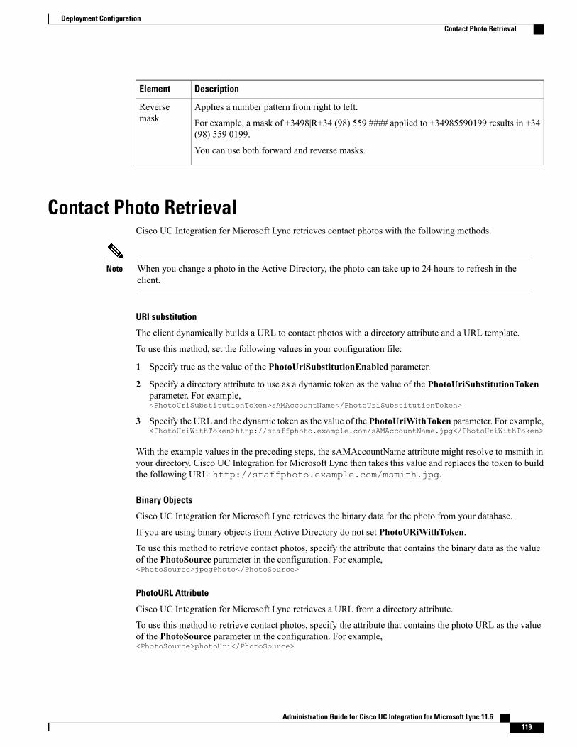
DescriptionElement
Applies a number pattern from right to left.
For example, a mask of +3498|R+34 (98) 559 #### applied to +34985590199 results in +34(98) 559 0199.
You can use both forward and reverse masks.
Reversemask
Contact Photo RetrievalCisco UC Integration for Microsoft Lync retrieves contact photos with the following methods.
When you change a photo in the Active Directory, the photo can take up to 24 hours to refresh in theclient.
Note
URI substitution
The client dynamically builds a URL to contact photos with a directory attribute and a URL template.
To use this method, set the following values in your configuration file:
1 Specify true as the value of the PhotoUriSubstitutionEnabled parameter.
2 Specify a directory attribute to use as a dynamic token as the value of the PhotoUriSubstitutionTokenparameter. For example,<PhotoUriSubstitutionToken>sAMAccountName</PhotoUriSubstitutionToken>
3 Specify the URL and the dynamic token as the value of the PhotoUriWithToken parameter. For example,<PhotoUriWithToken>http://staffphoto.example.com/sAMAccountName.jpg</PhotoUriWithToken>
With the example values in the preceding steps, the sAMAccountName attribute might resolve to msmith inyour directory. Cisco UC Integration for Microsoft Lync then takes this value and replaces the token to buildthe following URL: http://staffphoto.example.com/msmith.jpg.
Binary Objects
Cisco UC Integration for Microsoft Lync retrieves the binary data for the photo from your database.
If you are using binary objects from Active Directory do not set PhotoURiWithToken.
To use this method to retrieve contact photos, specify the attribute that contains the binary data as the valueof the PhotoSource parameter in the configuration. For example,<PhotoSource>jpegPhoto</PhotoSource>
PhotoURL Attribute
Cisco UC Integration for Microsoft Lync retrieves a URL from a directory attribute.
To use this method to retrieve contact photos, specify the attribute that contains the photo URL as the valueof the PhotoSource parameter in the configuration. For example,<PhotoSource>photoUri</PhotoSource>
Administration Guide for Cisco UC Integration for Microsoft Lync 11.6 119
Deployment ConfigurationContact Photo Retrieval
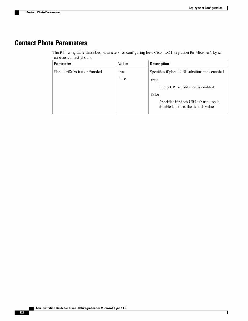
Contact Photo ParametersThe following table describes parameters for configuring how Cisco UC Integration for Microsoft Lyncretrieves contact photos:
DescriptionValueParameter
Specifies if photo URI substitution is enabled.
true
Photo URI substitution is enabled.
false
Specifies if photo URI substitution isdisabled. This is the default value.
true
false
PhotoUriSubstitutionEnabled
Administration Guide for Cisco UC Integration for Microsoft Lync 11.6120
Deployment ConfigurationContact Photo Parameters

DescriptionValueParameter
Specifies a directory attribute to insert in thephoto URI; for example, sAMAccountName.
Only the following attributes are supported foruse with the PhotoURISubstitutionTokenparameter:
• Common Name
• Display Name
• First Name
• Last Name
• Nickname
• Email Address
• Photo Source
• Business Phone
• Mobile Phone
• Home Phone
• Preferred Phone
• Other Phone
• Title
• Company Name
• User Account Name
• Domain Name
• Location
• Post Code
• State
• City
• Street
Directoryattribute
PhotoUriSubstitutionToken
Specifies a photo URI with a directory attributeas a variable value; for example,http://staffphoto.example.com/sAMAccountName.jpg.
To configure photo URI substitution, you set thedirectory attribute as the value ofPhotoUriSubstitutionToken.
The client must be able to retrieve the photosfrom the web server without credentials
URIPhotoUriWithToken
Administration Guide for Cisco UC Integration for Microsoft Lync 11.6 121
Deployment ConfigurationContact Photo Parameters

Contact ResolutionContact Resolution Parameters
The following table describes parameters for configuring intradomain federation:DescriptionValueParameter
Specifies whether Cisco UC Integration forMicrosoft Lync retrieves contact informationusing the value of the attribute you specify inthe SipUri parameter.
• true—Retrieve contact information usingthe value of the attribute you specify in theSipUri parameter.
You should specify true if the contact usernames in your directory do not conform tothe following format username@domain.
• false(default)—Cisco UC Integration forMicrosoft Lync does not use the SipUriparameter.
true
false
UseSIPURIToResolveContacts
Defines the prefix that applies to the value ofthe attribute you specify in the SipUri parameter.
The prefix is any text that exists before theusername of the contact ID. For example, youspecify msRTCSIP-PrimaryUserAddress as thevalue of SipUri. In your directory the value ofthe msRTCSIP-PrimaryUserAddress attributehas the following format:sip:username@domain.
The default value is blank.
Text stringUriPrefix
Specifies the directory attribute field that the IMAddress scheme field is mapped to.
To ensure that contacts are resolved, the valuefrom SipUri must match [UserID]@[domain]
msRTCSIP-PrimaryUserAddress
SipUri
Specifies the domain name used for creatinginstant messaging addresses for directorycontacts.username@domain
Text stringPresenceDomain
Administration Guide for Cisco UC Integration for Microsoft Lync 11.6122
Deployment ConfigurationContact Resolution
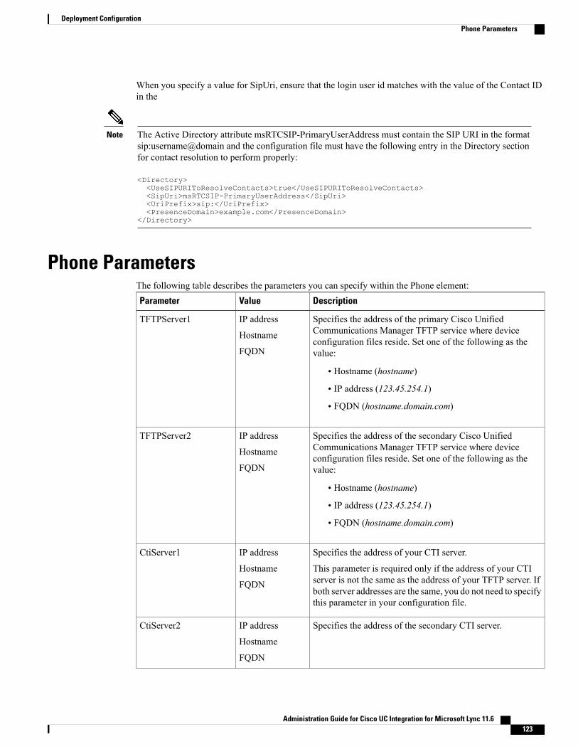
When you specify a value for SipUri, ensure that the login user id matches with the value of the Contact IDin the
The Active Directory attribute msRTCSIP-PrimaryUserAddress must contain the SIP URI in the formatsip:username@domain and the configuration file must have the following entry in the Directory sectionfor contact resolution to perform properly:
<Directory><UseSIPURIToResolveContacts>true</UseSIPURIToResolveContacts><SipUri>msRTCSIP-PrimaryUserAddress</SipUri><UriPrefix>sip:</UriPrefix><PresenceDomain>example.com</PresenceDomain>
</Directory>
Note
Phone ParametersThe following table describes the parameters you can specify within the Phone element:
DescriptionValueParameter
Specifies the address of the primary Cisco UnifiedCommunications Manager TFTP service where deviceconfiguration files reside. Set one of the following as thevalue:
• Hostname (hostname)
• IP address (123.45.254.1)
• FQDN (hostname.domain.com)
IP address
Hostname
FQDN
TFTPServer1
Specifies the address of the secondary Cisco UnifiedCommunications Manager TFTP service where deviceconfiguration files reside. Set one of the following as thevalue:
• Hostname (hostname)
• IP address (123.45.254.1)
• FQDN (hostname.domain.com)
IP address
Hostname
FQDN
TFTPServer2
Specifies the address of your CTI server.
This parameter is required only if the address of your CTIserver is not the same as the address of your TFTP server. Ifboth server addresses are the same, you do not need to specifythis parameter in your configuration file.
IP address
Hostname
FQDN
CtiServer1
Specifies the address of the secondary CTI server.IP address
Hostname
FQDN
CtiServer2
Administration Guide for Cisco UC Integration for Microsoft Lync 11.6 123
Deployment ConfigurationPhone Parameters
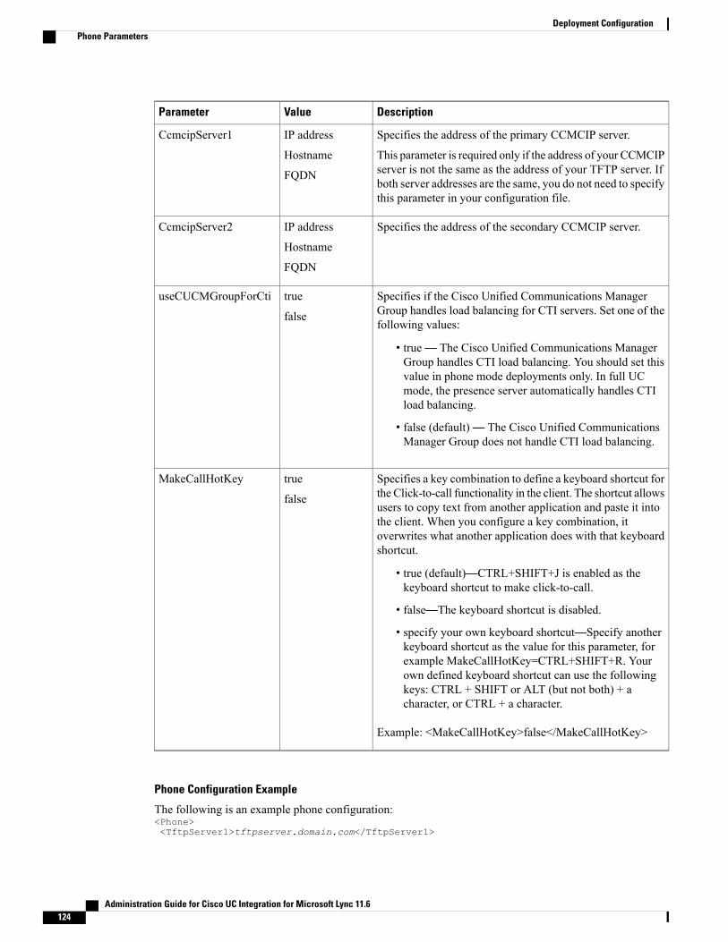
DescriptionValueParameter
Specifies the address of the primary CCMCIP server.
This parameter is required only if the address of your CCMCIPserver is not the same as the address of your TFTP server. Ifboth server addresses are the same, you do not need to specifythis parameter in your configuration file.
IP address
Hostname
FQDN
CcmcipServer1
Specifies the address of the secondary CCMCIP server.IP address
Hostname
FQDN
CcmcipServer2
Specifies if the Cisco Unified Communications ManagerGroup handles load balancing for CTI servers. Set one of thefollowing values:
• true— The Cisco Unified Communications ManagerGroup handles CTI load balancing. You should set thisvalue in phone mode deployments only. In full UCmode, the presence server automatically handles CTIload balancing.
• false (default)— The Cisco Unified CommunicationsManager Group does not handle CTI load balancing.
true
false
useCUCMGroupForCti
Specifies a key combination to define a keyboard shortcut forthe Click-to-call functionality in the client. The shortcut allowsusers to copy text from another application and paste it intothe client. When you configure a key combination, itoverwrites what another application does with that keyboardshortcut.
• true (default)—CTRL+SHIFT+J is enabled as thekeyboard shortcut to make click-to-call.
• false—The keyboard shortcut is disabled.
• specify your own keyboard shortcut—Specify anotherkeyboard shortcut as the value for this parameter, forexample MakeCallHotKey=CTRL+SHIFT+R. Yourown defined keyboard shortcut can use the followingkeys: CTRL + SHIFT or ALT (but not both) + acharacter, or CTRL + a character.
Example: <MakeCallHotKey>false</MakeCallHotKey>
true
false
MakeCallHotKey
Phone Configuration Example
The following is an example phone configuration:<Phone><TftpServer1>tftpserver.domain.com</TftpServer1>
Administration Guide for Cisco UC Integration for Microsoft Lync 11.6124
Deployment ConfigurationPhone Parameters

<CtiServer1>ctiserver.domain.com</CtiServer1></Phone>
Registry Key Configuration
The application supports obtaining the location of CCMCIP, CTI, TFTP servers, and useCUCMGroupForCtivalues from the Microsoft Windows registry. The following registry values can be used to specify theseservers:
• TftpServer1
• TftpServer2
• CtiServer1
• CtiServer2
• CcmcipServer1
• CcmcipServer2
• useCUCMGroupForCti
The application will first search for these values in HKEY_CURRENT_USER\Software\Cisco Systems,
Inc.\Client Services Framework\AdminData and then HKEY_CURRENT_USER\Software\Policies\Cisco
Systems, Inc.\Client Services Framework\AdminData. Values located in these registry keys will overrideinformation specified in the configuration file. Values will be read from the configuration file if they cannotbe found in either of these registry locations.
Policy ParametersThe following table describes the parameters you can specify within the Policies element in the configurationfile:
DescriptionValueParameter
Specifies if a user can pickup a call in their call pickupgroup.
• true—Enables call pickup.
• false (default)—Disables call pickup.
Example: <EnableCallPickup>true</EnableCallPickup>
true
false
EnableCallPickup
Specifies if a user can pickup incoming calls in anothercall pickup group, by entering the call pickup groupnumber.
• true—Enables group call pickup.
• false (default)—Disables group call pickup.
Example: <EnableGroupCallPickup>true</EnableGroupCallPickup>
true
false
EnableGroupCallPickup
Administration Guide for Cisco UC Integration for Microsoft Lync 11.6 125
Deployment ConfigurationPolicy Parameters

DescriptionValueParameter
Specifies if a user can pickup an incoming call in a groupthat is associated with their own call pickup group.
• true—Enables other group call pickup.
• false (default)—Disables other group call pickup.
Example: <EnableOtherGroupPickup>true</EnableOtherGroupPickup>
true
false
EnableOtherGroupPickup
Specifies if a user can log into a hunt group.
• true—Users can log into their hunt group.
• false (default)—Users cannot log into their huntgroup.
Example: <EnableHuntGroup>true</EnableHuntGroup>
true
false
EnableHuntGroup
Specifies if the Decline button is displayed for an incomingcall in a hunt group.
• true—Decline button is not displayed for an incomingcall in a hunt group.
• false (default)—Decline button is displayed for anincoming call in a hunt group.
Example:<PreventDeclineOnHuntCall>true</PreventDeclineOnHuntCall>
true
false
PreventDeclineOnHuntCall
Specifies the source of analytic information. This can bea string that explicitly identifies an individual customer ora string that identifies a common source without identifyingthe customer. Cisco recommends using a Global UniqueIdentifier (GUID) generating utility to generate a 36character unique identifier or to use a reverse domain name.The following utilities are available for generating a GUID:
• Mac OS X - uuidgen
• Linux - uuidgen
• Microsoft Windows - [guid]::NewGuid().ToString()or (from cmd.exe) powershell -command"[guid]::NewGuid().ToString()"
• Online - guid.us
This identifier should be globally unique regardless of themethod used to create the GUID.
Example:<TelemetryCustomerID>customerIdentifier</TelemetryCustomerID>
StringTelemetryCustomerID
Administration Guide for Cisco UC Integration for Microsoft Lync 11.6126
Deployment ConfigurationPolicy Parameters

DescriptionValueParameter
Specifies whether users sign in by using single sign-on(SSO).
• TRUE (default)—Users sign in by using SSO.
• FALSE—Users do not use SSO to sign in.
Example: <SSO_Enabled>FALSE</SSO_Enabled>
TRUE
FALSE
SSO_Enabled
Enables URI dialing with Cisco UC Integration forMicrosoft Lync and allows users to make calls with URIs.
• true—Users can make calls with URIs.
• false (Default)—Users can't make calls with URIs.
Example: <EnableSIPURIDialling>true
</EnableSIPURIDialling>
true
false
EnableSIPURIDialling
Specifies whether the user is shown the email prompt forthe purposes of determining their home cluster.
• ON—The prompt is shown.
• OFF (default)—The prompt is not shown.
Example:<ServicesDomainSsoEmailPrompt>ON</ServicesDomainSsoEmailPrompt>
ON
OFF
ServicesDomainSsoEmailPrompt
Specifies if the client registers as the protocol handler forthe tel: URI.
• true (default)—The client registers as the protocolhandler for the tel: URI.
• false—The client does not register as the protocolhandler for the tel: URI.
Example:<EnableTelProtocol>false</EnableTelProtocol>
true
false
EnableTelProtocol
Specifies if the client registers as the protocol handler forthe IM: URI.
• true (default)—The client registers as the protocolhandler for the IM: URI.
• false—The client does not register as the protocolhandler for the IM: URI.
Example:<EnableIMProtocol>false</EnableIMProtocol>
true
false
EnableImProtocol
Administration Guide for Cisco UC Integration for Microsoft Lync 11.6 127
Deployment ConfigurationPolicy Parameters
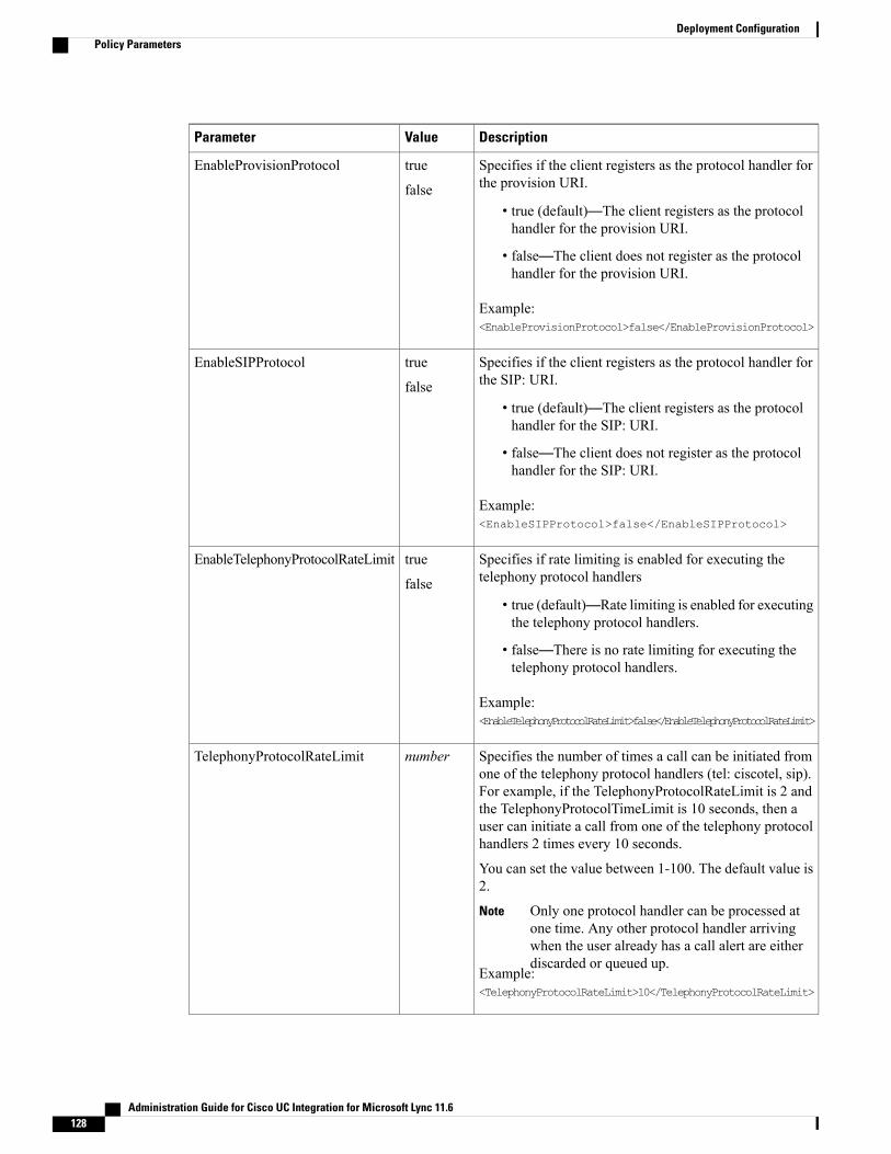
DescriptionValueParameter
Specifies if the client registers as the protocol handler forthe provision URI.
• true (default)—The client registers as the protocolhandler for the provision URI.
• false—The client does not register as the protocolhandler for the provision URI.
Example:<EnableProvisionProtocol>false</EnableProvisionProtocol>
true
false
EnableProvisionProtocol
Specifies if the client registers as the protocol handler forthe SIP: URI.
• true (default)—The client registers as the protocolhandler for the SIP: URI.
• false—The client does not register as the protocolhandler for the SIP: URI.
Example:<EnableSIPProtocol>false</EnableSIPProtocol>
true
false
EnableSIPProtocol
Specifies if rate limiting is enabled for executing thetelephony protocol handlers
• true (default)—Rate limiting is enabled for executingthe telephony protocol handlers.
• false—There is no rate limiting for executing thetelephony protocol handlers.
Example:<EnableTelephonyProtocolRateLimit>false</EnableTelephonyProtocolRateLimit>
true
false
EnableTelephonyProtocolRateLimit
Specifies the number of times a call can be initiated fromone of the telephony protocol handlers (tel: ciscotel, sip).For example, if the TelephonyProtocolRateLimit is 2 andthe TelephonyProtocolTimeLimit is 10 seconds, then auser can initiate a call from one of the telephony protocolhandlers 2 times every 10 seconds.
You can set the value between 1-100. The default value is2.
Only one protocol handler can be processed atone time. Any other protocol handler arrivingwhen the user already has a call alert are eitherdiscarded or queued up.
Note
Example:<TelephonyProtocolRateLimit>10</TelephonyProtocolRateLimit>
numberTelephonyProtocolRateLimit
Administration Guide for Cisco UC Integration for Microsoft Lync 11.6128
Deployment ConfigurationPolicy Parameters

DescriptionValueParameter
Specifies the time within which a user can initiate a callfrom one of the telephony protocol handlers (sip, tel,ciscotel) before the TelephonyProtocolRateLimit is hit orreset. The default value for initiating a call from one of thetelephony protocol handlers is 10 seconds for every 2attempts. You can set the value between 1-300 seconds.
Example:<TelephonyProtocolTimeLimit>10</TelephonyProtocolTimeLimit>
numberTelephonyProtocolTimeLimit
Defines the level of security for PRT logging by specifyingwhether logs are written to disc for desktop clients.
• Always (default)—Logs are always written to disc.No option appears in the client Help menu.
• UserCanEnable—Allows users to decide whetherlogs are written to disc or not. Setting this valuecreates an Enable Detailed Logging option in theHelp menu of the client that the user can enable ordisable.
• Never—Logs are never written to disc. When a PRTis manually generated, in-memory logs are flushedto a temporary file that is deleted as soon as the PRTis generated.
Example:<LogWritingDesktop>UserCanEnable</LogWritingDesktop>
LogWritingDesktop
If you configure the LogWritingDesktop parameter withthe value UserCanEnable, then this parameter defines thenumber of hours that the desktop client writes logs to thedisc. After the defined period expires, all logs are clearedfrom the disc. If you do not specify a value for thisparameter (default), then the client writes logs to the discindefinitely, or until the user disables detailed logging.
Example:<DetailedLogDurationDesktop>10</DetailedLogDurationDesktop>
DetailedLogDurationDesktop
Voicemail ParametersThe following table describes the voicemail service configuration parameters you can specify within theVoicemail element:
Administration Guide for Cisco UC Integration for Microsoft Lync 11.6 129
Deployment ConfigurationVoicemail Parameters
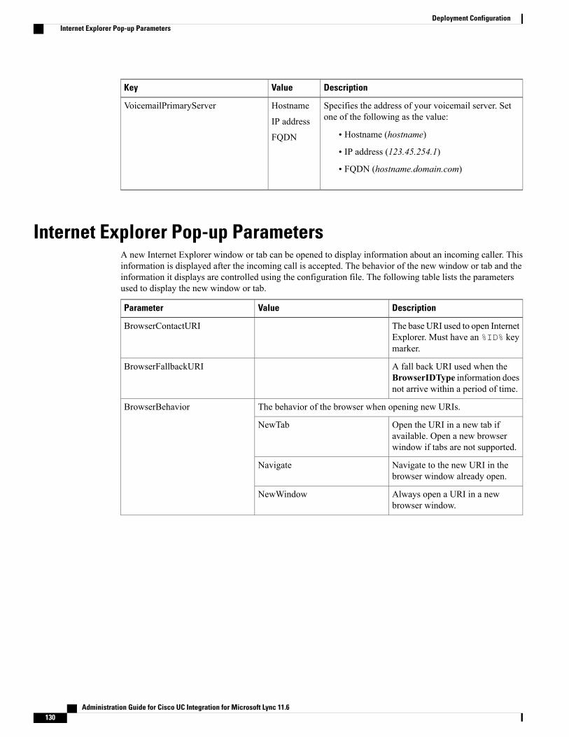
DescriptionValueKey
Specifies the address of your voicemail server. Setone of the following as the value:
• Hostname (hostname)
• IP address (123.45.254.1)
• FQDN (hostname.domain.com)
Hostname
IP address
FQDN
VoicemailPrimaryServer
Internet Explorer Pop-up ParametersA new Internet Explorer window or tab can be opened to display information about an incoming caller. Thisinformation is displayed after the incoming call is accepted. The behavior of the new window or tab and theinformation it displays are controlled using the configuration file. The following table lists the parametersused to display the new window or tab.
DescriptionValueParameter
The base URI used to open InternetExplorer. Must have an %ID% keymarker.
BrowserContactURI
A fall back URI used when theBrowserIDType information doesnot arrive within a period of time.
BrowserFallbackURI
The behavior of the browser when opening new URIs.BrowserBehavior
Open the URI in a new tab ifavailable. Open a new browserwindow if tabs are not supported.
NewTab
Navigate to the new URI in thebrowser window already open.
Navigate
Always open a URI in a newbrowser window.
NewWindow
Administration Guide for Cisco UC Integration for Microsoft Lync 11.6130
Deployment ConfigurationInternet Explorer Pop-up Parameters

DescriptionValueParameter
The type of ID supplied to the URI defined in the registry.BrowserIDType
The media address of theparticipant
CallNumber
The display name of the participantCallDisplayName
The business number of the contactContactBusinessNumber
The mobile number of the contactContactMobileNumber
The home number of the contactContactHomeNumber
The other number of the contactContactOtherNumber
The display name of the contactContactDisplayName
The URI of the contact([email protected] for example)
ContactURI
The email of the contact([email protected] for example)
ContactEmail
The user logon name of the contact.ContactUsername
A filter applied to the chosenBrowserIDType that will preventa new browser window or tab if amatch is made. The following areexamples of regular expressions:
• Phone number that has fourdigits and doesn't start withnumber 7: (?!7)\d{4}
• Phone number that doesn'tstart with the digits 1, 2, 3 or4: [5-90]\d+
• Phone number that doesn'tend with 49: \d+(?!49)\d{2}
Any valid regular expressionsupported by the Microsoftstd::tr1::regex library can be used.
Regular expressionBrowserIDFilter
Note the following items when implementing this feature:
• A new browser window or tab is displayed when the user accepts a transferred call from an establishedincoming call.
• A new browser window or tab is displayed for each additional, unique call participant added to aconference call.
Administration Guide for Cisco UC Integration for Microsoft Lync 11.6 131
Deployment ConfigurationInternet Explorer Pop-up Parameters
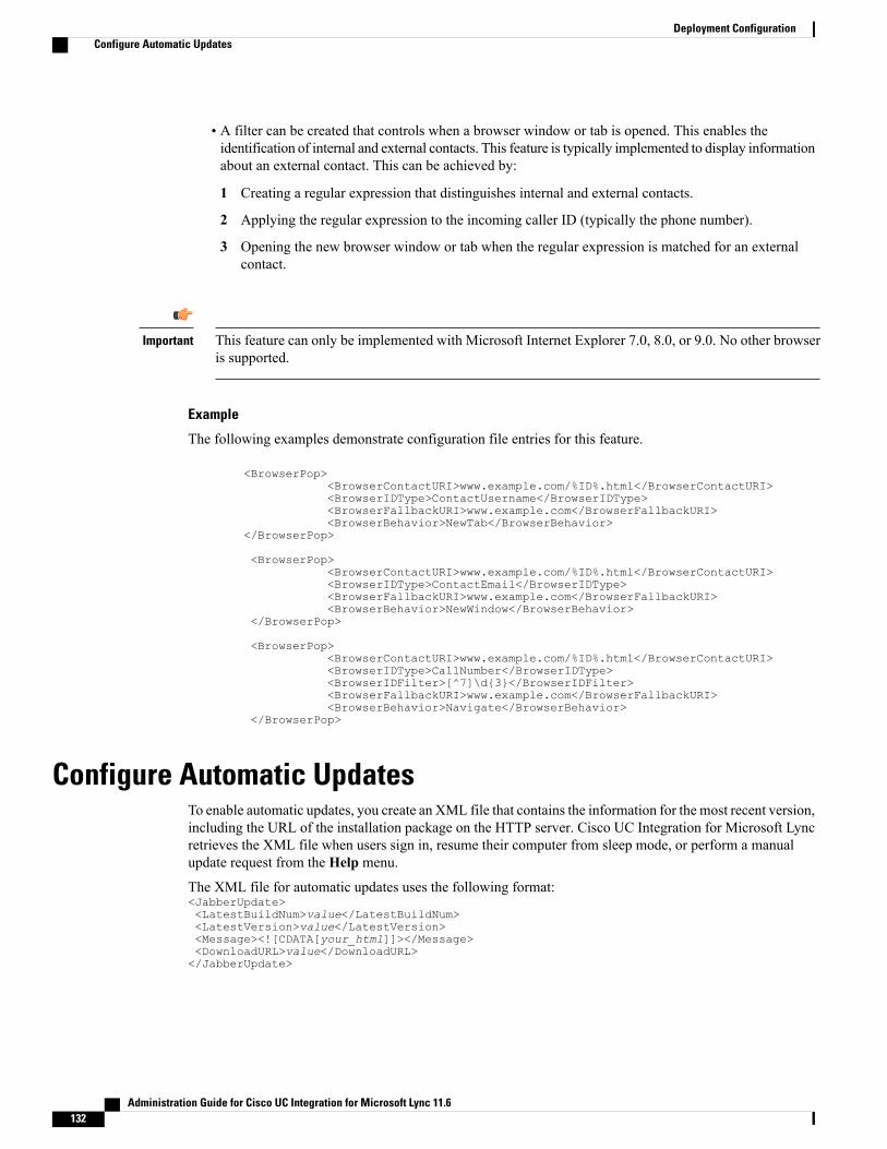
• A filter can be created that controls when a browser window or tab is opened. This enables theidentification of internal and external contacts. This feature is typically implemented to display informationabout an external contact. This can be achieved by:
1 Creating a regular expression that distinguishes internal and external contacts.
2 Applying the regular expression to the incoming caller ID (typically the phone number).
3 Opening the new browser window or tab when the regular expression is matched for an externalcontact.
This feature can only be implemented with Microsoft Internet Explorer 7.0, 8.0, or 9.0. No other browseris supported.
Important
Example
The following examples demonstrate configuration file entries for this feature.
<BrowserPop><BrowserContactURI>www.example.com/%ID%.html</BrowserContactURI><BrowserIDType>ContactUsername</BrowserIDType><BrowserFallbackURI>www.example.com</BrowserFallbackURI><BrowserBehavior>NewTab</BrowserBehavior>
</BrowserPop>
<BrowserPop><BrowserContactURI>www.example.com/%ID%.html</BrowserContactURI><BrowserIDType>ContactEmail</BrowserIDType><BrowserFallbackURI>www.example.com</BrowserFallbackURI><BrowserBehavior>NewWindow</BrowserBehavior>
</BrowserPop>
<BrowserPop><BrowserContactURI>www.example.com/%ID%.html</BrowserContactURI><BrowserIDType>CallNumber</BrowserIDType><BrowserIDFilter>[^7]\d{3}</BrowserIDFilter><BrowserFallbackURI>www.example.com</BrowserFallbackURI><BrowserBehavior>Navigate</BrowserBehavior>
</BrowserPop>
Configure Automatic UpdatesTo enable automatic updates, you create an XML file that contains the information for the most recent version,including the URL of the installation package on the HTTP server. Cisco UC Integration for Microsoft Lyncretrieves the XML file when users sign in, resume their computer from sleep mode, or perform a manualupdate request from the Help menu.
The XML file for automatic updates uses the following format:<JabberUpdate><LatestBuildNum>value</LatestBuildNum><LatestVersion>value</LatestVersion><Message><![CDATA[your_html]]></Message><DownloadURL>value</DownloadURL></JabberUpdate>
Administration Guide for Cisco UC Integration for Microsoft Lync 11.6132
Deployment ConfigurationConfigure Automatic Updates

Before You Begin
To configure automatic updates for Cisco UC Integration for Microsoft Lync, you must have an HTTP serverinstalled and configured to host the XML file and installation package.
Procedure
Step 1 Host the appropriate installation package on your HTTP server.Step 2 Create an update XML file with any text editor.Step 3 Specify the build number of the update as the value of the LatestBuildNum element.Step 4 Specify the version number of the update as the value of the LatestVersion element.Step 5 Specify HTML as the value of the Message element in the format: <![CDATA[your_html]]>Step 6 Specify the URL of the installation package on your HTTP server as the value of the DownloadURL element.Step 7 Save and close your update XML file.Step 8 Host your update XML file on your HTTP server.Step 9 Specify the URL of your update XML file as the value of the UpdateUrl parameter in your configuration file.
The following is an example of XML to configure automatic updates:<JabberUpdate><LatestBuildNum>12345</LatestBuildNum><LatestVersion>9.2.1</LatestVersion><Message><![CDATA[<b>This new version of Cisco UC Integration for Microsoft Lync lets youdo the following:</b><ul><li>Feature 1</li><li>Feature 2</li></ul>Formore information click <a target="_blank"href="http://cisco.com/go/cucilync">here</a>.]]></Message><DownloadURL>http://server_name/CUCILyncSetup.msi</DownloadURL></JabberUpdate>
Configure Problem ReportingSetting up problem reporting enables users to send a summary of issues that they encounter while using CiscoUC Integration for Microsoft Lync. There are two methods for submitting problem reports as follows:
• Users submit the problem report directly through Cisco UC Integration for Microsoft Lync.
• Users save the problem report locally and then upload it at a later time.
Cisco UC Integration for Microsoft Lync uses an HTTP POST method to submit problem reports. Create acustom script to accept the POST request and specify the URL of the script on your HTTP server as aconfiguration parameter. Because users can save problem reports locally, you should also create an HTMLpage with a form to enable users to upload problem reports.
Before You Begin
Complete the following steps to prepare your environment:
1 Install and configure an HTTP server.2 Create a custom script to accept the HTTP POST request.
Administration Guide for Cisco UC Integration for Microsoft Lync 11.6 133
Deployment ConfigurationConfigure Problem Reporting
3 Create an HTML page to host on the HTTP server to enable users to upload problem reports that are savedlocally. Your HTML page should contain a form that accepts the problem report saved as a .ZIP archiveand contains an action to post the problem report using your custom script.
The following is an example form that accepts problem reports:<form name="uploadPrt" action="http://server_name.com/scripts/UploadPrt.php" method="post"enctype="multipart/form-data"><input type="file" name="zipFileName" id="zipFileName" /><br /><input type="submit" name="submitBtn" id="submitBtn" value="Upload File" /></form>
Procedure
Step 1 Host your custom script on your HTTP server.Step 2 Specify the URL of your script as the value of the PrtLogServerUrl parameter in your configuration file.
PRT Options
Encryption and Decryption of PRTs
You can configure if the PRT logs are encrypted. Use the EnablePrtEncryption parameter to specify if thePRT files are encrypted. When you set the EnablePrtEncryption to true, specify the Certificate name in thePrtCertificateName parameter. The PrtCertificateName value is a certificate with a public key in the EnterpriseTrust or Trusted Root Certificate Authorities certificate store and is used to encrypt the PRTs.
PRT Logging Levels
You can configure the different logging levels for PRTs using the LogWritingDesktop andDetailedLogDurationDesktop parameters. Use the LogWritingDesktop parameter to determine the following:
• Logs are always written to disk with no user configurations available.
• An option is available in the client for users to decide if the logs are written to disk. You can limit theduration that logs are written with the DetailedLogDurationDesktop parameter, if there is no value forthis parameter then logs are written indefinitely.
• Logs are never written to disk.
Decrypt the Problem ReportThe command line tool CiscoJabberPrtDecrypter.exe for decrypting the problem reports is only availableon Windows machines and is included in the installer. The tool has the following arguments:
• --help—Show the help message.
• --privatekey—Specify the private key file, this is a privacy enhanced mail (.pem) or a personalinformation exchange PKCS#12 (.pfx) format.
• --password—Optional, if the input private key file is password protected.
Administration Guide for Cisco UC Integration for Microsoft Lync 11.6134
Deployment ConfigurationPRT Options

• --encryptionkey—Specify the encryption secret key file, for example file.zip.esk.
• --encryptedfile—Specify the encrypted file, for example file.zip.enc.
• --outputfile—Specify the output file, for example decryptedfile.zip.
Before You Begin
To decrypt problem reports you need the following:
• Two files from the zip file created when you generated a problem report using encryption:
• file.zip.esk—The encrypted symmetric key.
• file.zip.enc—The original data encrypted using AES256.
• Private Key for the certificate used for encrypting the data.
Procedure
Step 1 Open a command prompt in Windows.Step 2 Navigate to the C:\Program Files(x86)\Cisco Systems\CUCILync\ directory.Step 3 Enter the command and your parameters.
Example for desktop clients: CiscoJabberPrtDecrypter.exe --privatekey C:\PRT\PrivateKey.pfx
--password 12345 --encryptedfile C:\PRT\file.zip.enc --encryptionkey C:\PRT\file.zip.esk
--outputfile C:\PRT\decryptedfile.zip
If the decryption is successful the output file is created. If there is an invalid parameter the decryption failsand an error is shown on the command line.
Custom Embedded TabsCustom embedded tabs display HTML content in the client interface. Learn how to create custom embeddedtab definitions for Cisco UC Integration for Microsoft Lync.
Custom Embedded Tab DefinitionsThe custom embedded tab can only be configured using the jabber-config.xml file. The followingXML snippet shows the structure for custom tab definitions:<jabber-plugin-config><browser-plugin><page refresh="" preload=""><tooltip></tooltip><icon></icon><url></url></page></browser-plugin></jabber-plugin-config>
Administration Guide for Cisco UC Integration for Microsoft Lync 11.6 135
Deployment ConfigurationCustom Embedded Tabs

The client supports Internet Explorer version 9 or earlier. The client uses Internet Explorer in version 9 modeif a later version is on the workstation.
The following table describes the parameters for custom embedded tab definitions:DescriptionParameter
Contains all definitions for custom embedded tabs.
The value includes all custom tab definitions.
browser-plugin
Contains one custom embedded tab definition.page
Controls when the content refreshes.
• true— Content refreshes each time users select the tab.
• false (default)— Content refreshes when users restart the client or signin.
This parameter is optional and is an attribute of the page element.
refresh
Controls when the content loads.
• true— Content loads when the client starts.
• false (default)— Content loads when users select the tab.
This parameter is optional and is an attribute of the page element.
preload
Defines hover text for the custom embedded tab.
This parameter is optional. If you do not specify the hover text, the client willuse Custom tab.
The value is string of unicode characters.
tooltip
Specifies an icon for the tab. You can specify a local or hosted icon as follows:
• Local icon—Specify the URL as follows:file://file_path/icon_name
• Hosted icon—Specify theURLas follows:http://path/icon_name
You can use any icon that the client browser can render can render, including.JPG, .PNG, and .GIF formats.
This parameter is optional. If you do not specify an icon, the client loads thefavicon from the HTML page. If no favicon is available, the client loads thedefault icon.
icon
Specifies the URL where the content for the embedded tab resides.
The client uses the browser rendering engine to display the content of theembedded tab. For this reason, you can specify any content that the browsersupports.
This parameter is required.
url
Administration Guide for Cisco UC Integration for Microsoft Lync 11.6136
Deployment ConfigurationCustom Embedded Tab Definitions

User Custom TabsUsers can create their own custom embedded tabs through the client user interface.
You must enable users to create custom embedded tabs. Set true as the value for the AllowUserCustomTabsparameter in your configuration file as follows:<Options><AllowUserCustomTabs>true</AllowUserCustomTabs>
</Options>
User custom embedded tabs are set to true by default.Note
Custom IconsTo achieve optimal results, your custom icon should conform to the following guidelines:
• Dimensions: 20 x 20 pixels
• Transparent background
• PNG file format
UserID TokensYou can specify the ${UserID} token as part of the value for the url parameter. When users sign in, theclient replaces the ${UserID} token with the username of the logged in user.
You can also specify the ${UserID} token in query strings; for example,www.cisco.com/mywebapp.op?url=${UserID}.
Tip
The following is an example of how you can use the ${UserID} token:
1 You specify the following in your custom embedded tab:<url>www.cisco.com/${UserID}/profile</url>
2 Mary Smith signs in. Her username is msmith.
3 The client replaces the ${UserID} token with Mary's username as follows:<url>www.cisco.com/msmith/profile</url>
JavaScript NotificationsYou can implement JavaScript notifications in custom embedded tabs. This topic describes the methods theclient provides for JavaScript notifications. This topic also gives you an example JavaScript form that you
Administration Guide for Cisco UC Integration for Microsoft Lync 11.6 137
Deployment ConfigurationUser Custom Tabs
can use to test notifications. It is beyond the scope of this documentation to describe how to implementJavaScript notifications for asynchronous server calls and other custom implementations. You should referto the appropriate JavaScript documentation for more information.
Notification Methods
The client includes an interface that exposes the following methods for JavaScript notifications:
• SetNotificationBadge— You call this method from the client in your JavaScript. This method takes astring value that can have any of the following values:
• Empty— An empty value removes any existing notification badge.
• A number from 1 to 999
• Two digit alphanumeric combinations, for example, A1
• onPageSelected()— The client invokes this method when users select the custom embedded tab.
• onPageDeselected()— The client invokes this method when users select another tab.
Show Call Events in Custom TabsYou can use the following JavaScript function to show call events in a custom tab:
OnTelephonyConversationStateChanged— An API in the telephony service enables the client to show callevents in a custom embedded tab. Custom tabs can implement theOnTelephonyConversationStateChanged JavaScript function. The client calls this function everytime a telephony conversation state changes. The function accepts a JSON string that the client parses to getcall events.
The following snippet shows the JSON that holds the call events:{
"conversationId": string,"acceptanceState": "Pending" | "Accepted| | "Rejected","state": "Started" | "Ending" | "Ended","callType": "Missed" | "Placed" | "Received" | "Passive" | "Unknown","remoteParticipants": [{participant1}, {participant2}, …, {participantN}],"localParticipant": {}
}
Each participant object in the JSON can have the following properties:{
"voiceMediaDisplayName": "<displayName>","voiceMediaNumber": "<phoneNumber>","translatedNumber": "<phoneNumber>","voiceMediaPhoneType": "Business" | "Home" | "Mobile" | "Other" | "Unknown","voiceMediaState": "Active" | "Inactive" | "Pending" | "Passive" | "Unknown",
}
The following is an example implementation of this function in a custom embedded tab. This example getsthe values for the state and acceptanceState properties and shows them in the custom tab.function OnTelephonyConversationStateChanged(json) {
console.log("OnTelephonyConversationStateChanged");try {var conversation = JSON.parse(json);console.log("conversation id=" + conversation.conversationId);console.log("conversation state=" + conversation.state);console.log("conversation acceptanceState=" + conversation.acceptanceState);
Administration Guide for Cisco UC Integration for Microsoft Lync 11.6138
Deployment ConfigurationShow Call Events in Custom Tabs

console.log("conversation callType=" + conversation.callType);}catch(e) {console.log("cannot parse conversation:" + e.message);
}}
The following is an example implementation of this function with all possible fields:function OnTelephonyConversationStateChanged(json) {
console.log("OnTelephonyConversationStateChanged");try {var conversation = JSON.parse(json);console.log("conversation state=" + conversation.state);console.log("conversation acceptanceState=" + conversation.acceptanceState);console.log("conversation callType=" + conversation.callType);for (var i=0; i<conversation.remoteParticipants.length; i++) {console.log("conversation remoteParticipants[" + i + "]=");console.log("voiceMediaDisplayName=" +
conversation.remoteParticipants[i].voiceMediaDisplayName);console.log("voiceMediaNumber=" +
conversation.remoteParticipants[i].voiceMediaNumber);console.log("translatedNumber=" +
conversation.remoteParticipants[i].translatedNumber);console.log("voiceMediaPhoneType=" +
conversation.remoteParticipants[i].voiceMediaPhoneType);console.log("voiceMediaState=" +
conversation.remoteParticipants[i].voiceMediaState);}console.log("conversation localParticipant=");console.log(" voiceMediaDisplayName=" +
conversation.localParticipant.voiceMediaDisplayName);console.log(" voiceMediaNumber=" + conversation.localParticipant.voiceMediaNumber);
console.log(" translatedNumber=" + conversation.localParticipant.translatedNumber);
console.log(" voiceMediaPhoneType=" +conversation.localParticipant.voiceMediaPhoneType);
console.log(" voiceMediaState=" + conversation.localParticipant.voiceMediaState);}catch(e) {console.log("cannot parse conversation:" + e.message);
}}
Custom Embedded Tab ExampleThe following is an example of a configuration file with one embedded tab:<?xml version="1.0" encoding="utf-8"?><config version="1.0"><Client><jabber-plugin-config><browser-plugin><page refresh ="true" preload="true"><tooltip>Cisco</tooltip><icon>http://www.cisco.com/web/fw/i/logo.gif</icon><url>http://www.cisco.com</url></page></browser-plugin></jabber-plugin-config></Client></config>
Administration Guide for Cisco UC Integration for Microsoft Lync 11.6 139
Deployment ConfigurationCustom Embedded Tab Example
Configuration File ExampleThe following is an example of a configuration file.<?xml version="1.0" encoding="utf-8"?><config version="1.0"><Client><PrtLogServerUrl>http://server_name.domain.com/prt_script.php</PrtLogServerUrl><UpdateUrl>http://server_name.domain.com/update.xml</UpdateUrl><Forgot_Password_URL>http://server_name.domain.com/password.html</Forgot_Password_URL>
</Client><Directory><DirectoryServerType>EDI</DirectoryServerType><BusinessPhone>aNonDefaultTelephoneNumberAttribute</BusinessPhone><PhotoUriSubstitutionEnabled>true</PhotoUriSubstitutionEnabled><PhotoUriSubstitutionToken>cn</PhotoUriSubstitutionToken><PhotoUriWithToken>http://staffphoto.example.com/cn.jpg</PhotoUriWithToken>
</Directory></config>
Registry Key ConfigurationCisco UC Integration for Microsoft Lync supports obtaining the parameters listed in this document in theWindows registry. The application will first search for these values in HKEY_CURRENT_USER\Software\CiscoSystems, Inc.\Client Services Framework\AdminData and thenHKEY_CURRENT_USER\Software\Policies\Cisco Systems, Inc.\Client Services Framework\AdminData.Values located in these registry keys will override information specified in the configuration file. Values willbe read from the configuration file if they cannot be found in either of these registry locations.
Administration Guide for Cisco UC Integration for Microsoft Lync 11.6140
Deployment ConfigurationConfiguration File Example

C H A P T E R 10Troubleshoot Cisco UC Integration for MicrosoftLync
The section contains information on resolving common issues with Cisco UC Integration for Microsoft Lync.
• Configuration Issues, page 141
• Directory Integration Issues, page 143
• Audio, Video, and Device Issues, page 144
Configuration IssuesTFTP and CCMCIP Server Configuration Not Working
Problem description: The TFTP and CCMCIP server values specified in the configuration file are not usedby the application.
Resolution: The TFTP and CCMCIP servers can be configured using the configuration file or through registrykey settings. Ensure that the misconfigured values are not specified in a registry setting. Registry key valuesfor the TFTP and CCMCIP servers take precedence over the configuration file on a key by key basis. SeePhone Parameters, on page 123 for more information on this feature. Registry key values for TFTP andCCMCIP servers are only supported at this time.
Configuration File Is Not Downloaded from the TFTP Server
Problem description: Cisco UC Integration for Microsoft Lync does not download the configuration filefrom the TFTP server. The configuration file is not available in the installation directory after you start CiscoUC Integration for Microsoft Lync.
Resolution:
1 Restart your TFTP server.2 Check the name of your configuration file.
Administration Guide for Cisco UC Integration for Microsoft Lync 11.6 141

Remember • The name of the configuration file is case sensitive.
• The global configuration filename must be jabber-config.xml.
3 Ensure your corporate firewall does not prevent Cisco UC Integration forMicrosoft Lync from downloadingthe configuration file.
4 Host the configuration file on your TFTP server as follows:
a Open the Cisco Unified OS Administration interface.b Select Software Upgrades > TFTP File Management.c Select Upload File.d Select Browse in the Upload File section.e Select the configuration file on the file system.f Leave the value of the Directory text box empty to host the configuration file in the default directory
of your TFTP server.g Select Upload File.
Cisco UC Integration for Microsoft Lync Does Not Read the Configuration File
Problem description:You host a global or group configuration file on your TFTP server. Cisco UC Integrationfor Microsoft Lync downloads the configuration file and saves it in the appropriate installation directory.However, Cisco UC Integration forMicrosoft Lync does not apply any settings you specify in the configurationfile.
Resolution: Ensure the XML in the configuration file is valid. Cisco UC Integration for Microsoft Lyncconfiguration files must do the following:
• Use utf-8 encoding.
• Contain only valid XML character entities. For example, use & instead of &.Open your configuration file in Microsoft Internet Explorer to determine if any characters or entities arenot valid. If Internet Explorer displays the entire XML structure, your configuration file does not containinvalid characters or entities. If Internet Explorer displays only part of the XML structure, yourconfiguration file most likely contains invalid characters or entities.
• Contain a valid structure. Ensure parameters are nested under the correct elements. The following XMLsnippet shows the basic structure of a configuration file:<?xml version="1.0" encoding="utf-8"?><config version="1.0"><Client><parameter_name>value</parameter_name></Client><Directory><parameter_name>value</parameter_name></Directory><Policies><parameter_name>value</parameter_name></Policies></config>
Administration Guide for Cisco UC Integration for Microsoft Lync 11.6142
Troubleshoot Cisco UC Integration for Microsoft LyncConfiguration Issues
Cisco UC Integration for Microsoft Lync Uses Old Configuration Settings
Problem description:Cisco UC Integration for Microsoft Lync is not using the current configuration settings.You change settings in a configuration file and host it on your TFTP server. However, Cisco UC Integrationfor Microsoft Lync uses the settings from the previous version of the configuration file.
Resolution:
1 Restart your TFTP server.2 Open the configuration file in your browser to verify the settings. Typically, you can access the configuration
file at the following URL: http://tftp_server_address:6970/jabber-config.xml
If restarting your TFTP server does not resolve this issue, it is likely that Cisco UC Integration for MicrosoftLync uses the cached configuration file because it cannot download the current version.
Microsoft Outlook Contacts Are Not Displayed in Search Results
Problem description:Microsoft Outlook contacts are not displayed in search results.
Resolution:Review the following requirements to ensure users can search for and communicate withMicrosoftOutlook contacts:
• To search for local contacts in Microsoft Outlook using Cisco UC Integration for Microsoft Lync, usersmust have profiles set in Microsoft Outlook.
• To add local contacts in Microsoft Outlook to contact lists in Cisco UC Integration for Microsoft Lync,user profiles must have email or instant message addresses.
• To communicate with local contacts in Microsoft Outlook using Cisco UC Integration for MicrosoftLync, user profiles must contain the relevant details. For example, to send instant messages to contactsin Microsoft Outlook, the user profiles must have email or instant message addresses. Likewise, to callcontacts in Microsoft Outlook, the user profiles must contain phone numbers.
Directory Integration IssuesCannot Determine If a Directory Connection Is Established
Problem description:You specify directory settings in a Cisco UC Integration forMicrosoft Lyncconfigurationfile. However, you are not sure whether Cisco UC Integration for Microsoft Lync is successfully connectedto the directory.
Resolution: Perform the following steps to determine whether Cisco UC Integration for Microsoft Lync isconnected to the directory:
1 Start the client.2 Enter at least three characters in the search field.
If Cisco UC Integration for Microsoft Lync displays a list of matching contacts, search is working. Cisco UCIntegration for Microsoft Lync is successfully connected to the directory.
If Cisco UC Integration for Microsoft Lync is not successfully connected to the directory, review theconfiguration settings. By default, the client uses Enhanced Directory Integration and connects to a GlobalCatalog server.
Administration Guide for Cisco UC Integration for Microsoft Lync 11.6 143
Troubleshoot Cisco UC Integration for Microsoft LyncDirectory Integration Issues
ADSI Error CodesCisco UC Integration for Microsoft Lync uses Microsoft Active Directory Service Interfaces (ADSI) fordirectory integration. You should refer to the ADSI error codes to help troubleshoot directory integrationissues.
See the following Microsoft documentation for information about ADSI error codes:
• ADSI Error Codes at http://msdn.microsoft.com/en-us/library/windows/desktop/aa772195(v=vs.85).aspx
• Generic ADSI Error Codes at http://msdn.microsoft.com/en-us/library/windows/desktop/aa705940(v=vs.85).aspx
• Error Codes for ADSI 2.5 at http://support.microsoft.com/kb/242076
Audio, Video, and Device Issues
The section contains information on troubleshooting audio, video, and device issues related to Cisco UCIntegration for Microsoft Lync. Refer to the Microsoft Lync documentation for troubleshooting issuesrelated to Microsoft Lync.
Note
Microsoft Lync Devices Are Not Available
Devices configured inMicrosoft Lyncmust be independently configured in Cisco UC Integration forMicrosoftLync.
Audio and Video Communication Is Not Available
Problem description: You provision audio and video devices, but cannot connect to the devices.
Resolution: Ensure you set up a CTI gateway and create a CCMCIP profile on Cisco Unified CommunicationsManager as appropriate.
Voicemail Prompt Is Truncated
Problem description: The start of voicemail prompts is truncated.
The start of the audio that prompts users to leave voicemail messages can be truncated in some instances. Theresult of the truncation is that users do not hear the first second or two of the voicemail prompt.
Resolution
To resolve this issue, set a value for the Delay After Answer field in the Cisco Unity Connection advancedtelephony integration settings. See the Cisco Unity Connection advanced telephony integration settings. Seethe Cisco Unity Connection documentation at: http://www.cisco.com/en/US/docs/voice_ip_comm/connection/8x/gui_reference/guide/8xcucgrg120.html#wp1056978
Administration Guide for Cisco UC Integration for Microsoft Lync 11.6144
Troubleshoot Cisco UC Integration for Microsoft LyncADSI Error Codes
End Users Cannot Retrieve Phone Account Details
Problem description: Cisco UC Integration for Microsoft Lync users cannot retrieve phone account detailswhen they log in to an extension mobility profile. As a result, error messages display in the Phone servicessection of the Phone accounts tab on the Options dialog box.
The affected users have multiple devices configured on Cisco Unified Communications Manager.
The following exceptions are written to the csf-unified.log file in the%USER_PROFILE%\AppData\Local\Cisco\Unified Communications\Jabber\CSF\Logsdirectory:<time_stamp> DEBUG [0x00001d80] [src\config\CCMCIPClient.cpp(230)] [csf.ecc][curlDebugCallback] -<html><body>org.apache.jasper.JasperException: java.lang.reflect.InvocationTargetException<br><!--org.apache.jasper.JasperException: java.lang.reflect.InvocationTargetExceptionatorg.apache.jasper.runtime.JspRuntimeLibrary.handleSetPropertyExpression(JspRuntimeLibrary.java:622)atorg.apache.jsp.ControlledDevices_jsp._jspx_meth_c_005fforEach_005f0(ControlledDevices_jsp.java:834)at org.apache.jsp.ControlledDevices_jsp._jspService(ControlledDevices_jsp.java:180)at org.apache.jasper.runtime.HttpJspBase.service(HttpJspBase.java:70)at javax.servlet.http.HttpServlet.service(HttpServlet.java:722)
Resolution: To resolve this issue, do the following:
1 Disassociate the affected users from all extension mobility profiles.
2 Contact your Cisco support representative and request an Engineering Special (ES) to resolve this issueon Cisco Unified Communications Manager.
After you apply the ES on Cisco Unified Communications Manager, you can re-associate the affected userswith the extension mobility profiles.
Calls Drop Intermittently on Network Profile Change
Problem description: Audio and video calls drop intermittently when the network profile changes.
A known bug exists with Microsoft Windows 7 and Microsoft Windows Server 2008 R2 that causes thenetwork profile to change unexpectedly. This change in the network profile closes network ports that CiscoUC Integration for Microsoft Lync requires for calls. As a result, if you are on a call when the network profilechanges, that call automatically terminates.
Resolution: Apply the fix available from the Microsoft support site at: http://support.microsoft.com/kb/2524478/en-us
Administration Guide for Cisco UC Integration for Microsoft Lync 11.6 145
Troubleshoot Cisco UC Integration for Microsoft LyncAudio, Video, and Device Issues

Administration Guide for Cisco UC Integration for Microsoft Lync 11.6146
Troubleshoot Cisco UC Integration for Microsoft LyncAudio, Video, and Device Issues