adt 406 s - fcc id search€™s handbook page 5 june 6/05 table of illustrations page figure 1 :...
TRANSCRIPT
USER’S HANDBOOK
Documentation P/N: 04E66260 Rev A Initial issue: June 6/05
Title Page June 6/05
USER’S HANDBOOK
INCLUDING INSTALLATION MANUAL AND LOG BOOK
EMERGENCY LOCATOR TRANSMITTER
MODEL ADT 406 S
IN THE COSPAS / SARSAT SYSTEM
Issued by
ELTA
F6614 14 Place Marcel Dassault
31702 BLAGNAC France
www.elta.fr
SERIAL NUMBER LABEL
USER’S HANDBOOK
Page 1 June 6/05
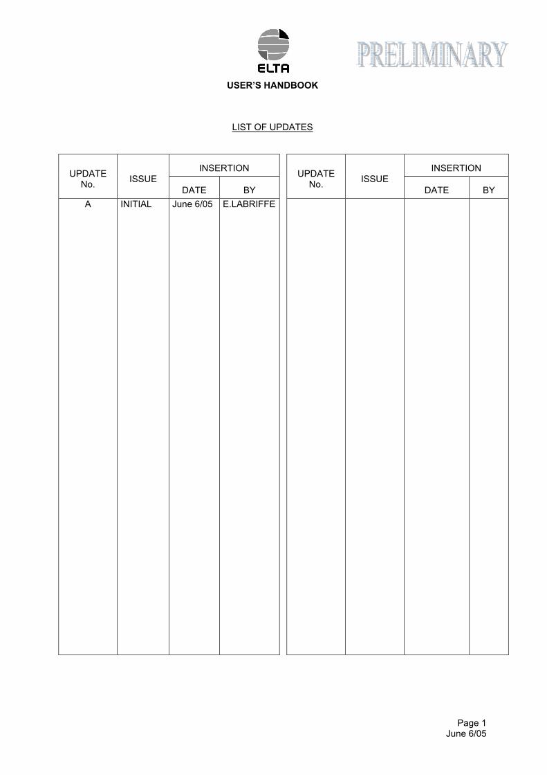
LIST OF UPDATES
INSERTION INSERTION UPDATE
No. ISSUE
DATE BY
UPDATE No.
ISSUE
DATE BY
A
INITIAL
June 6/05
E.LABRIFFE
USER’S HANDBOOK
Page 2 BLANK
PAGE INTENTIONALLY LEFT BLANK
USER’S HANDBOOK
Page 3 June 6/05
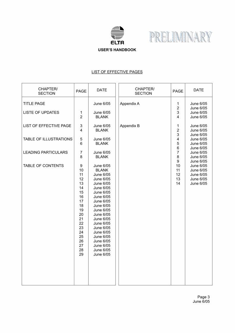
LIST OF EFFECTIVE PAGES
CHAPTER/ SECTION
PAGE DATE
CHAPTER/ SECTION
PAGE DATE
TITLE PAGE LISTE OF UPDATES LIST OF EFFECTIVE PAGE TABLE OF ILLUSTRATIONS LEADING PARTICULARS TABLE OF CONTENTS
1 2 3 4 5 6 7 8 9 10 11 12 13 14 15 16 17 18 19 20 21 22 23 24 25 26 27 28 29
June 6/05
June 6/05 BLANK
June 6/05 BLANK
June 6/05 BLANK
June 6/05 BLANK
June 6/05 BLANK
June 6/05 June 6/05 June 6/05 June 6/05 June 6/05 June 6/05 June 6/05 June 6/05 June 6/05 June 6/05 June 6/05 June 6/05 June 6/05 June 6/05 June 6/05 June 6/05 June 6/05 June 6/05 June 6/05
Appendix A Appendix B
1 2 3 4 1 2 3 4 5 6 7 8 9 10 11 12 13 14
June 6/05 June 6/05 June 6/05 June 6/05
June 6/05 June 6/05 June 6/05 June 6/05 June 6/05 June 6/05 June 6/05 June 6/05 June 6/05 June 6/05 June 6/05 June 6/05 June 6/05 June 6/05

USER’S HANDBOOK
Page 4 BLANK
PAGE INTENTIONALLY LEFT BLANK
USER’S HANDBOOK
Page 5 June 6/05
TABLE OF ILLUSTRATIONS Page
Figure 1 : COSPAS/SARSAT - System Principle 12 Figure 2 : ELT ADT 406 S Presentation 14 Figure 3 : ELT ADT 406 S – Dimensions (Basic Configuration) 15 Figure 4 : Installation of the ELT ADT 406 S - Drilling Pattern Dimensions 22 Figure 5 : ELT ADT 406 S - Detailed Description 29

USER’S HANDBOOK
Page 6 BLANK
PAGE INTENTIONALLY LEFT BLANK
USER’S HANDBOOK
Page 7 June 6/05
LEADING PARTICULARS
CAUTION 1 : THIS TRANSMITTER IS AUTHORIZED FOR USE ONLY DURING SITUATIONS OF GRAVE AND IMMINENT DANGER.
CAUTION 2 : IT IS IMPERATIVE THAT EACH BEACON OWNER REGISTERS THEIR BEACON. CONTACT ELTA OR APPROVED AGENT TO OBTAIN THE INFORMATION RELATIVE TO THIS REGISTRATION.
CAUTION 3 : THE BEACON MUST IMPERATIVELY BE PROGRAMMED WITH THE RELEVANT IDENTIFICATION AUTHORIZED BY THE LOCAL AIRWORTHINESS.
CAUTION 4 : ONCE THE BEACON HAS BEEN PROGRAMMED, IT IS GENERALY ASSIGNED TO AN AIRCRAFT (NAME AND IDENTIFICATION). IF THIS BEACON IS USED ON ANOTHER AIRCRAFT IT WOULD HAVE TO BE REPROGRAMMED (NEW NAME AND IDENTIFICATION).
CAUTION 5 : BEFORE INSTALLING OR USING THIS EQUIPMENT, THE VALIDITY OF THE INFORMATION ON THE BEACON LABEL MUST IMPERATIVELY BE CHECKED.

USER’S HANDBOOK
Page 8 BLANK
PAGE INTENTIONALLY LEFT BLANK
USER’S HANDBOOK
Page 9 June 6/05
TABLE OF CONTENTS
PAGE
1. INTRODUCTION TO THE COSPAS-SARSAT SYSTEM 11 A. The COSPAS-SARSAT system 11 B. System organization 11 C. The distress frequencies 13 D. ELTA and the COSPAS-SARSAT system 13 2. GENERAL DETAILS OF THE ELT ADT 406 S 14 A. Purpose of the ELT ADT 406 S 14 B. Characteristics 16 3. DESCRIPTION OF THE ELT ADT 406 S 18 A. General description 18 B. Detailed description 18 4. INSTALLATION OF THE ELT ADT 406 S 21 A. General 21 B. Installation of the beacon on the aircraft 21 C. Installation and configuration of the beacon 23 5. UTILIZATION OF THE ELT ADT 406 S 24 A. Automatic activation 24 B. Manual activation 24 C. Remove beacon from the support 25 C. Beacon shutdown 26 D. Beacon self-test 26 6. MAINTENANCE OF THE ELT ADT 406 S 27
A. Beacon self-test 27 B. Water Sensor test 27
C. Maintenance periodicity table 27 D. Battery replacement 27 E. Battery discarding 28 F. Test to do at the time of a beacon return in workshop 28
USER’S HANDBOOK
Page 10 BLANK
PAGE INTENTIONALLY LEFT BLANK
USER’S HANDBOOK
Page 11 June 6/05
1. INTRODUCTION TO THE COSPAS-SARSAT SYSTEM
A. The COSPAS-SARSAT* system
The purpose of the COSPAS-SARSAT satellite system is to detect and locate all distress signals transmitted by aeronautical, maritime or land-based beacons, for the search and rescue organizations.
This program is the result of an international collaboration between the United States, Canada and France on the one hand (SARSAT project), and Russia on the other hand (COSPAS project). These two projects are fully compatible.
Since the first results were obtained several countries have joined the program. Several other countries have shown an interest and will soon be joining the COSPAS-SARSAT system partners.
ELTA in relation with CNES (French National Space Agency) has developed the complete range of products required for COSPAS-SARSAT system operation.
Following an in-depth study phase, ELTA has arrived at highly conclusive technical results, and experimental and operational use of the "ground" equipment have proven this equipment's reliability and ease-of-use.
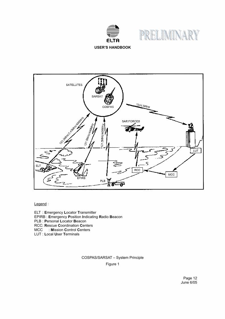
B. System organization (Ref. Fig. 1)
In the COSPAS-SARSAT system, space equipment is placed on board several satellites in low near-polar orbit to capture transmissions from emergency transmitters and to retransmit these signals to specialized ground stations called Local User Terminals (LUT). These ground stations determine the position of the
emergency transmitters and then retransmit the position data to the designated Mission Control Centers
(MCC). The MCCs in turn retransmit these data to the appropriate Rescue Coordination Centers (RCC) so that they can start the search and rescue operations.
* COSPAS-SARSAT : COSPAS = Kosmicheskaya Sistyema Poiska Avariynych Sudov SARSAT = Search and Rescue Satellite-Aided Tracking
USER’S HANDBOOK
Page 12 June 6/05
Legend :
ELT : Emergency Locator Transmitter
EPIRB : Emergency Position Indicating Radio Beacon PLB : Personal Locator Beacon
RCC : Rescue Coordination Centers
MCC : Mission Control Centers LUT : Local User Terminals
COSPAS/SARSAT – System Principle
Figure 1
USER’S HANDBOOK
Page 13 June 6/05
C. The distress frequencies
There are several advantages to using the 406 MHz frequency :
– Worldwide coverage: locating is not only possible in real-time within a radius of 2,500 km around the station, but also in global mode outside this zone since the satellites memorize the messages on the 406 MHz frequency. Location process uses Doppler effect.
– Locating accuracy: 2 km as opposed to 10 to 15 km in the 121.5 MHz or 243 MHz frequencies. It should
be noted however that the 406 MHz beacons also transmit 121.5 MHz and 243 MHz signals which enable the final approach of the rescue teams in homing mode.
– Information reliability: the structure of the digital signal transmitted by these beacons makes it possible to
be sure that there is actually a distress situation, as well as to identify automatically the mobile in distress which is vital for rescue operations.
– Unique identification: each beacon has it’s own identification information.
D. ELTA and the COSPAS-SARSAT system
(1)406 MHz distress beacons:
These beacons transmit to the satellites a digital message which identifies them and gives their position, as well as a signal that facilitates the final approach of the rescue teams.
They are suitable for all types of use (maritime, aeronautical and land) and can, depending on the model, be activated manually or automatically. They are designed to function in the most extreme conditions with a high degree of reliability.
(2)Satellites low earth orbiting:
At least four satellites are permanently operational. Since their orbit is near-polar, in the worst case every point on Earth is overflown every two hours.
In a ground station's visibility zone, the satellites directly transmit the messages captured in that zone, and also any messages from the zones not covered that they have stored in memory.
(3)Geo-stationary satellites are now available in the system and offer faster detection capability (close to 5 minutes) but require a GPS receiver to supply location that is sent via C/S message.
(4)Ground reception stations:
The zone effectively covered (or visibility zone) is a circle with a radius of 2,500 km around the station. These stations receive (via the satellites) and process, in real time, the messages from the beacons activated in their visibility zone and, in batch mode, the messages from the 406 MHz beacons activated outside that zone and memorized by the satellites.
Automatic processing of the 406 MHz digital messages allows the beacons to be located and the carrier mobile to be identified.
USER’S HANDBOOK
Page 14 June 6/05
2. GENERAL DETAILS OF THE ELT ADT 406 S
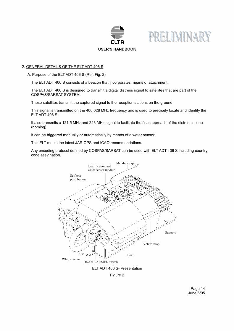
A. Purpose of the ELT ADT 406 S (Ref. Fig. 2)
The ELT ADT 406 S consists of a beacon that incorporates means of attachment.
The ELT ADT 406 S is designed to transmit a digital distress signal to satellites that are part of the COSPAS/SARSAT SYSTEM.
These satellites transmit the captured signal to the reception stations on the ground.
This signal is transmitted on the 406.028 MHz frequency and is used to precisely locate and identify the ELT ADT 406 S.
It also transmits a 121.5 MHz and 243 MHz signal to facilitate the final approach of the distress scene (homing).
It can be triggered manually or automatically by means of a water sensor.
This ELT meets the latest JAR OPS and ICAO recommendations.
Any encoding protocol defined by COSPAS/SARSAT can be used with ELT ADT 406 S including country code assignation.
ELT ADT 406 S- Presentation
Figure 2
Whip antenna
Support
Float
Metalic strapIdentification andwater sensor module
Self test
push button
Velcro strap
ON/OFF/ARMED switch
USER’S HANDBOOK
Page 15 June 6/05
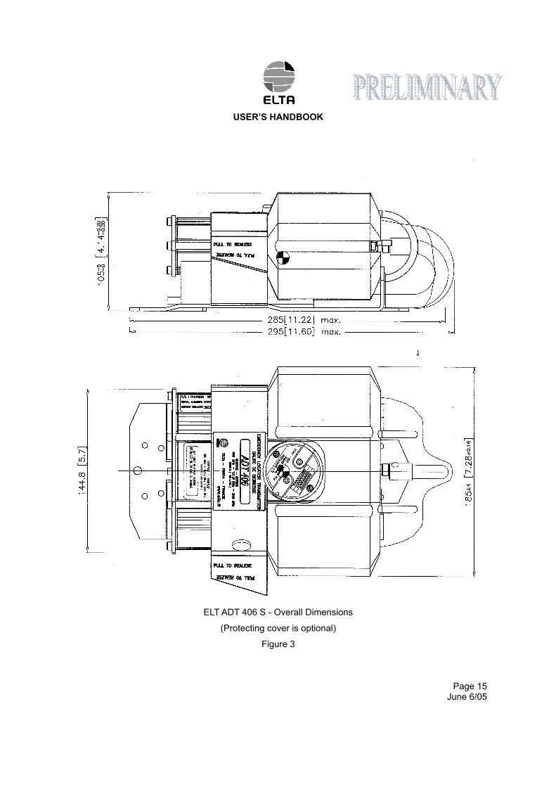
ELT ADT 406 S - Overall Dimensions
(Protecting cover is optional)
Figure 3
USER’S HANDBOOK
Page 16 June 6/05
B. Characteristics (Ref. Fig. 3)
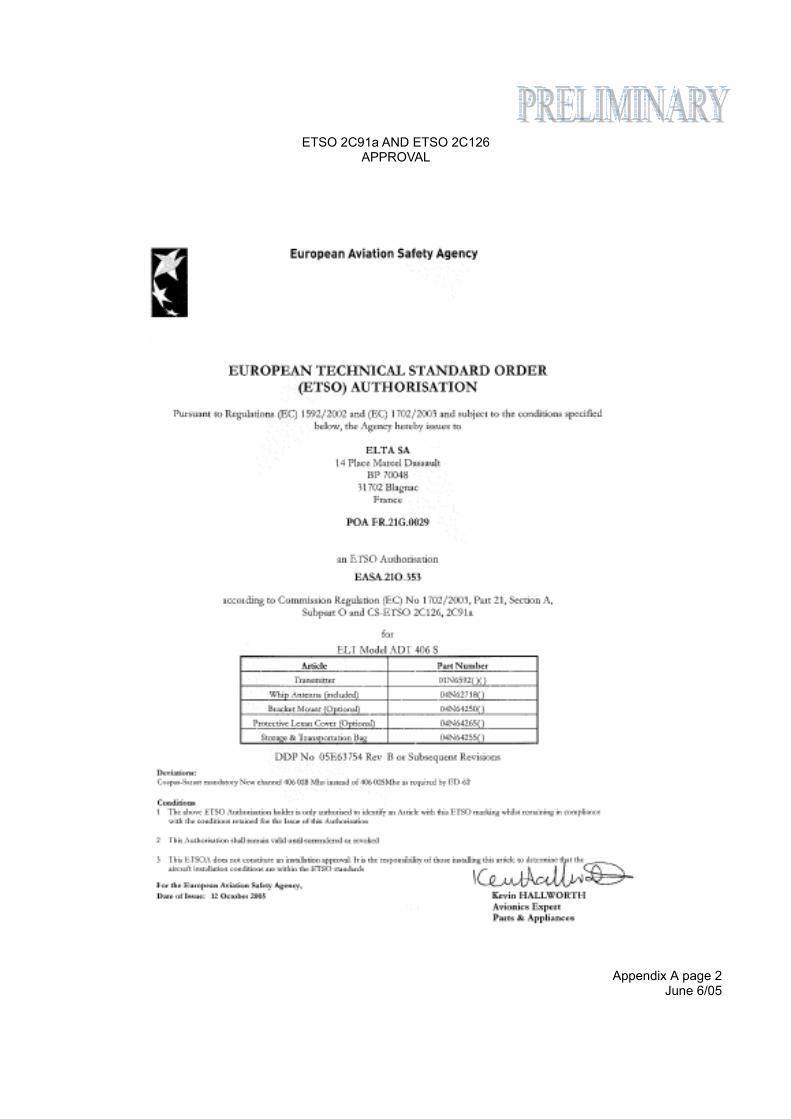
(1)Approvals
ADT 406 S is COSPAS/SARSAT approved (TAC 153, dated 15 sep. 2005)
ADT 406 S meets EUROCAE ED62 standard
ADT 406 S is ETSO 2C91a and ETSO 2C126 (ETSO N° EASA.21O.353 dated 12 October 2005)
ADT 406 S is TSO C91a and TSO C126 (TSO letter dated XXXXX)
(2)Physical characteristics
(a)Beacon with support
Height : 105 mm Width : 185 mm Length : 295 mm (with optional plastic cover) Weight : - Beacon (with antenna) : 1.6 Kg
- Bracket : 0.34 kg
- Optional protecting cover : 0.04 Kg
(b)Beacon only
Height : 94 mm Width : 185 mm Length : 221.5 mm (without back up antenna) Weight : 1.5 kg (with back up antenna) Length with back up antenna deployed : 540 mm
(3)General characteristics
(a)Whip antenna
– Omnidirectionnal three-frequency antenna 50Ω access, – conform to COSPAS/SARSAT and EUROCAE ED-62 specifications.
(b)Power supply
High energy batteries (2 series-connected packs), activable for 5 years. Autonomy 24 hours on 406.028
MHz and greater than 48 hours at -20°C on 121.5&243 MHz.
– Voltage : 6 VDC, – capacity : 10.5 A/h, – ELTA type number :00E64191, – lithium manganese dioxide (solid cathode), – battery servicing kit available: 02N60052 kit for one ELT
02N60053 kit for 10 ELT
USER’S HANDBOOK
Page 17 June 6/05
(c)Radio-electrical characteristics
1 406 MHz satellite transmitter
– Frequency : 406.028 MHz, – transmitter power : 5 W, – modulation : "L" two-phase, – transmission recurrence : 50 s, – transmission duration : 440 ms.
2 Associated homing transmitter
– Frequency : 121.5 MHz/243 Mhz or 121.5 MHz (selectable), – 121.5 MHz transmitter power : typical 100 mW, – 243 MHz transmitter power : typical 100 mW, – modulation : AM (3K20A3X type) from, 1600 Hz to 300 Hz,
up to four periods per second, – antenna gain : 1 dBi.
(d)Environment characteristics
– Operating temperatures : -20°C to +55°C,
– Storage temperatures : -55°C to +85°C, – Ambient temperature (20°C) is highly recommended for storage in order to reduce self discharge of
the batteries, when the equipment is stored with internal batteries.
(e)Miscellaneous characteristics
– Automatic activation by water sensor in armed mode.
– color : orange in conformity with the international distress signal,
– self-test : transmission of one burst modulated with inverted frame synchronization and 5s transmission of 121.5 MHz , automation to “ARMED” position,
– any COSPAS/SARSAT protocol available,
. ELT S/N
. A/C operator designator and S/N
. A/C 24 bits address
. A/C nationality and registration marking (recommended)
. Test – any country code available, – operate in short C/S message. – C/S identification stored in a transferable module to ease maintenance on ELT (Water sensor /
Identification module),
USER’S HANDBOOK
Page 18 June 6/05
3. DESCRIPTION OF THE ELT ADT 406 S
A. General description
(1)Introduction
This beacon from the ADT406 family derives from the ADT 406 AF/AP model. Consequently, this beacon features the functional capabilities of the AF/AP besides its flotation gear, the attachment interface and its flexible antenna entirely compatible with Cospat/Sarsat.
(2)The ELT ADT 406 essentially consists of :
– an ADT 406 S beacon transmitter – a whip antenna, – labels, – an water sensor / identification module, – a support or a flight bag. – An optional protecting cover (for bracket mounting only)
B. Detailed description (Ref. Fig. 7)
(1)The ADT 406 S beacon
The ADT 406 S beacon mainly consists of :
– a whip antenna, – a power supply module, – an electronic assembly, – a mechanical assembly, – a float.
The front face of the electronic assy is equipped with the following components :
– a WHIP ANT. TNC female connector (1) for connecting up the antenna, – an ARMED/OFF/ON lockable toggle switch (3) for activating the beacon, – an TEST push button (12) for beacon self test, – a TX indicator light (2) indicating beacon activation (real distress and self-test process).
USER’S HANDBOOK
Page 19 June 6/05
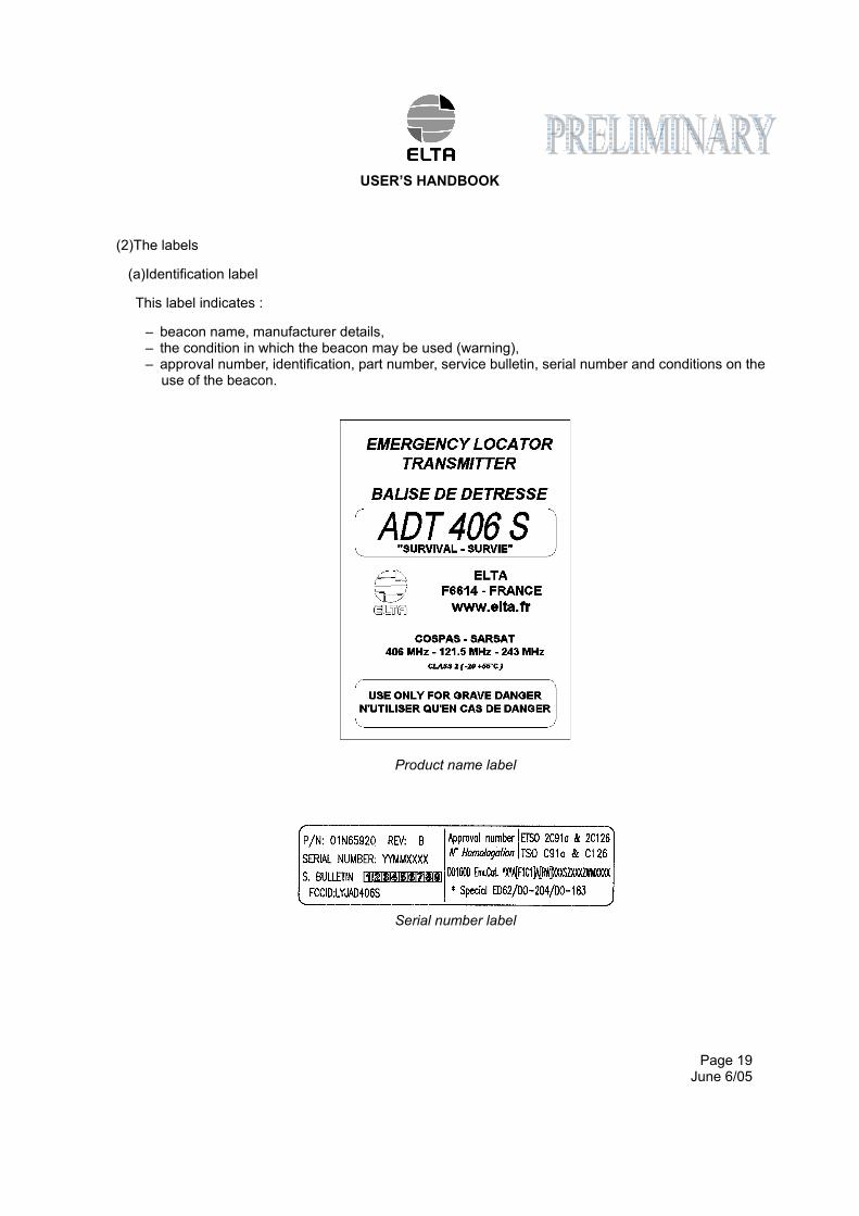
(2)The labels
(a)Identification label
This label indicates :
– beacon name, manufacturer details, – the condition in which the beacon may be used (warning), – approval number, identification, part number, service bulletin, serial number and conditions on the
use of the beacon.
Product name label
Serial number label
USER’S HANDBOOK
Page 20 June 6/05
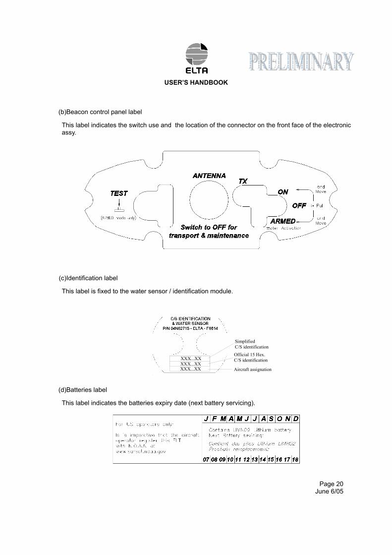
(b)Beacon control panel label
This label indicates the switch use and the location of the connector on the front face of the electronic assy.
(c)Identification label
This label is fixed to the water sensor / identification module.
(d)Batteries label
This label indicates the batteries expiry date (next battery servicing).
XXX...XXXXX...XXXXX...XX Aircraft assignation
Simplified
C/S identification
Official 15 Hex.
C/S identification
USER’S HANDBOOK
Page 21 June 6/05
4. INSTALLATION OF THE ELT ADT 406 S
A. General
System security and reliability obviously depends on the standard of installation.
In order to ensure installation of the highest standard, the installation operations must be :
– performed in conformity with this document, – performed in compliance with the current regulations, – performed by qualified personnel, – performed so that :
. the aircraft's structural integrity is not affected,
. it will not hinder the pilot in normal position,
. it will not cause any damage in the event of an accident,
. it will not prevent or modify operation of the other safety systems. If in doubt, contact the aircraft manufacturer or its representative,
– inspected by representative authority.
B. Installation of the beacon on the aircraft (Ref. Fig. 4)
The beacon shall be installed in any position in the aircraft , but the switch and the water sensor / identification module must be protected from passengers to exclude false activations.
Unstowed objects must be not able to impact the beacon.
In case of use the support, attach the beacon to the fuselage of the aircraft by means of four M4 bolts. Four 5 mm diameter holes at the corners of a 210 mm x 45 mm rectangle are drilled in the beacon support. Particular care must be taken with this attachment. Standard industry means must be used to lock the screws. Use flat washer in order to avoid paint damage.
The attachment points are similar to those of the ADT 406 AF/AP beacon.
USER’S HANDBOOK
Page 22 June 6/05
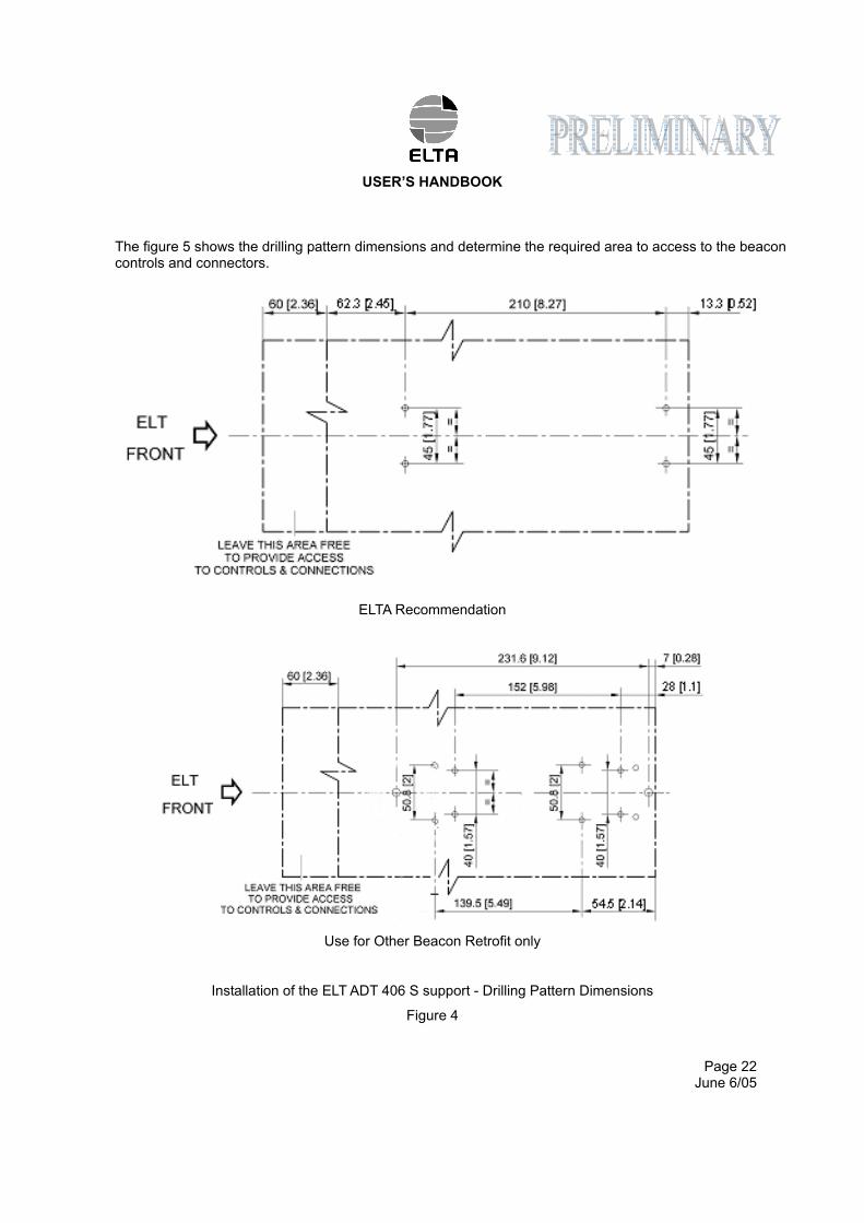
The figure 5 shows the drilling pattern dimensions and determine the required area to access to the beacon controls and connectors.
ELTA Recommendation
Use for Other Beacon Retrofit only
Installation of the ELT ADT 406 S support - Drilling Pattern Dimensions
Figure 4
USER’S HANDBOOK
Page 23 June 6/05
C. Installation and configuration of the beacon (Ref. Fig. 5)
(1)Installation in automatic survival mode (water activation)
CAUTION : TO BE OPERATIONAL, THE BEACON SHALL BE IN "ARMED" POSITION ONCE IT HAS BEEN CORRECTLY INSTALLED.
Make sure that the antenna is correctly connected to the TNC connector.
Switch the Beacon ARMED/OFF/ON lockable toggle switch to ARMED (pull and slide), the system is ready for use : water sensor is activated.
CAUTION : AS SOON AS THE BEACON IS IN ARMED IT CAN BE AUTOMATICALLY ACTIVATED BY THE WATER SENSOR .
USER’S HANDBOOK
Page 24 June 6/05
5. UTILIZATION OF THE ELT ADT 406 S (Ref. Fig. 5)
CAUTION : IN THE EVENT OF UNTIMELY BEACON ACTIVATION, SHUTDOWN THE BEACON AND INFORM THE CLOSEST SEARCH AND RESCUE (SAR) OR AIRPORT CONTROL TOWER IMMEDIATELY.
The ELT ADT 406 can be activated in two modes : – automatic when the water sensor is triggered, – manual. A. Automatic activation
The aircraft has to be evacuated, the beacon is removed from is support or bag and dip to the water with the survivals.
The water sensor has detected sufficient water to trigger it. The indicator light (2) and the aural indicator indicate beacon activation.
Do not do anything and leave the beacon in operation until the rescue team arrives.
B. Manual activation
There are two cases in which a distress signal may be triggered manually :
– the water sensor has not been triggered but a distress signal must be sent (injured passengers, aircraft out of operation ...),
– the aircraft is on the ground and must be evacuated.
From the beacon :
Place the beacon switch (3) in the ON position (pull and slide), and do not do anything.
An automatic self-test sequence is performed.
After the beacon enter in a waiting condition for about 30s. This state is displayed by flashing on indicator light (2) 1.75 s ON, 0.25 s OFF. This delay will avoid unwanted activation (false manoeuvre).
Then the indicator light (2) and the aural indicator indicate beacon activation. The actual distress signal is transmitted. This state is displayed by flashing on indicator light : 0.5 s ON, 0.5 s OFF.
CAUTION : IN THE TWO CASES OF ACTIVATION, MAKE SURE THAT THE ANTENNA MUST BE DEPLOYED AND IN VERTICAL POSITION. FOR MAXIMUM POWER TRANSMISSION THE ANTENNA MUST BE IN A UNOBSTRUCTED AREA FAR FROM ANY METALIC PIECES.
USER’S HANDBOOK
Page 25 June 6/05
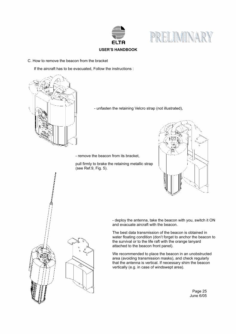
C. How to remove the beacon from the bracket
If the aircraft has to be evacuated, Follow the instructions :
- unfasten the retaining Velcro strap (not illustrated),
- remove the beacon from its bracket,
pull firmly to brake the retaining metallic strap (see Ref.9, Fig. 5).
- deploy the antenna, take the beacon with you, switch it ON and evacuate aircraft with the beacon.
The best data transmission of the beacon is obtained in water floating condition (don’t forget to anchor the beacon to the survival or to the life raft with the orange lanyard attached to the beacon front panel).
We recommended to place the beacon in an unobstructed area (avoiding transmission masks), and check regularly that the antenna is vertical. If necessary shim the beacon vertically (e.g. in case of windswept area).
USER’S HANDBOOK
Page 26 June 6/05
D. Beacon shutdown
In the event of a false manoeuvre or untimely operation, shutdown the beacon.
The beacon is shutdown by place the ARMED/OFF/ON toggle switch (3) in OFF position..
CAUTION : THE BEACON MUST BE SHUTDOWN BEFORE ANY MAINTENANCE OPERATIONS ARE PERFORMED. THE BEACON MUST BE COMPLETELY SHUTDOWN BEFORE IT IS REMOVED AND IT'S ARMED/OFF/ON TOGGLE SWITCH SHALL BE IN OFF POSITION.
E. Beacon self-test
CAUTION : THE SELF-TEST SHALL BE PERFORMED WITHIN THE FIRST 5.MN OF ANY HOUR BECAUSE THE ELT IS SENDING 121.5 MHZ SIGNAL FOR 5 S DURING THIS PROCESS (LIMITATION OF FALSE ALERT).
The ELT ADT 406 S is designed to perform a self-test, by using the TEST push button, when the ON/OFF/ARMED toggle switch is in ARMED position. Actual test transmission on 121.5 MHz for 5 s can be listen on any VHF receiver.
REMOVE THE BEACON FROM HIS BRACKET AND EXTAND THE ANTENNA BEFORE SELF-TEST, HOLD THE BEACON AT ARM’S LENGTH IN THE AISLE TO FREE THE ANTENNA FROM THE WALL.
Place the beacon's ARMED/OFF/ON toggle switch (3) in ARMED position to authorize self test process.
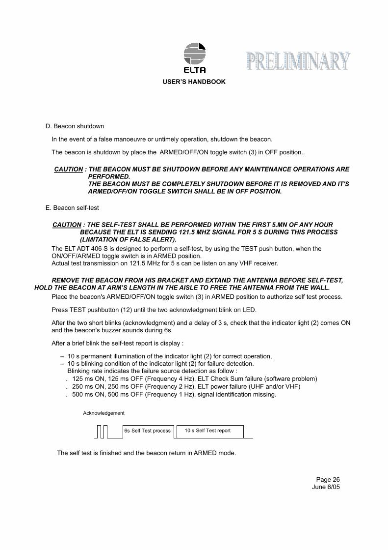
Press TEST pushbutton (12) until the two acknowledgment blink on LED.
After the two short blinks (acknowledgment) and a delay of 3 s, check that the indicator light (2) comes ON and the beacon's buzzer sounds during 6s.
After a brief blink the self-test report is display :
– 10 s permanent illumination of the indicator light (2) for correct operation, – 10 s blinking condition of the indicator light (2) for failure detection.
Blinking rate indicates the failure source detection as follow :
. 125 ms ON, 125 ms OFF (Frequency 4 Hz), ELT Check Sum failure (software problem)
. 250 ms ON, 250 ms OFF (Frequency 2 Hz), ELT power failure (UHF and/or VHF)
. 500 ms ON, 500 ms OFF (Frequency 1 Hz), signal identification missing.
The self test is finished and the beacon return in ARMED mode.
10 s Self Test report 6s Self Test process
Acknowledgement

USER’S HANDBOOK
Page 27 June 6/05
Fold up the antenna, put back the beacon in his braket and grip the strap.
USER’S HANDBOOK
Page 28 June 6/05
6. MAINTENANCE OF THE ELT ADT 406 S
A. Beacon self-test
The manufacturer recommends that a beacon self-test should be performed regularly. The highest rate is one per week. Generally, airlines added this task to other periodic maintenance task such a “A” check. In all events the user must comply with the applicable regulations in the country concerned governing the self-test period.
The self-test must only be performed when the order to do so is given or by the competent authorities.
A higher rate of self-test will reduce the 5 years battery servicing.
CAUTION : THE SELF-TEST PROCEDURE (PARAGRAPH 5.E.) MUST BE RESPECTED TO AVOID UNTIMELY BEACON ACTIVATION.
B. Water Sensor test
The water sensor should be tested at the periodic maintenance task. Place the ARMED/OFF/ON toggle switch (3) in ARMED, and make a short circuit between the two hexagon socket screws of the water sensor assy. This short circuit must during 2 at 3 second permanently to activate the beacon. When the beacon is activated switch OFF the beacon and return in ARMED if necessary. The water sensor work correctly.
C. Maintenance periodicity table
Periodicity Operations Operator
5 years Replacement of batteries ELTA or approved agent/airline
5 years General overhaul in specialized workshop
ELTA or approved agent/airline
D. Batteries replacement
CAUTION : THE BATTERY PACK SHALL BE APPROVED BY ELTA. IF OTHER PACK ARE USED ELTA WILL CANCEL WARRANTY AND WILL REFUSE ANY RESPONSIBILITY ON THE PRODUCT OPERATION / MISFUNCTION.
CAUTION : THE BATTERIES USED CANNOT BE RECHARGED. DO NOT TRY TO OPEN OR RECHARGE THEM.
Next battery servicing date is indicated on a label stuck on the back face of ADT 406 S. The old batteries must be replaced with new batteries of a model approved by ELTA P/N 05N62123 (battery servicing for one ELT ADT406 S).
ELTA recommends that the ELT ADT 406 S should undergo a general overhaul on its test and programming bench at this occasion.
Refer to CMM 25-60-11 for detail of operation.
USER’S HANDBOOK
Page 29 June 6/05
E. Batteries discarding
The batteries must be discarded in compliance with the applicable regulations in the country concerned.
NOTE : The type of battery used is not dangerous for the environment provided that it is completely discharged.
Contact ELTA for getting additional discarding information.
F. Test to do at the time of a beacon return in workshop
Perfoms the following tests described in CMM 25-60-11 :
– visual check, – test of water sensor automatic activation, – functional test of ADT 406 S beacon, – RF test on the operational frequencies 121.5 – 243 – 406 MHz.
USER’S HANDBOOK
Page 30 June 6/05
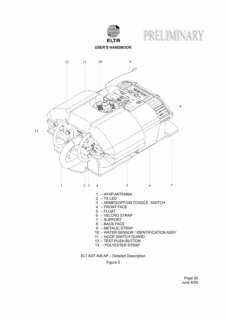
1 – WHIP ANTENNA 2 – TX LED 3 – ARMED/OFF/ON TOGGLE SWITCH 4 – FRONT FACE 5 – FLOAT 6 – VELCRO STRAP 7 – SUPPORT 8 – BACK FACE 9 – METALIC STRAP 10 – WATER SENSOR / IDENTIFICATION ASSY 11 – HOOP SWITCH GUARD 12 – TEST PUSH BUTTON 13 – POLYESTER STRAP
ELT ADT 406 AP – Detailed Description
Figure 5
1 432 5 6 7
8
91012
13
11
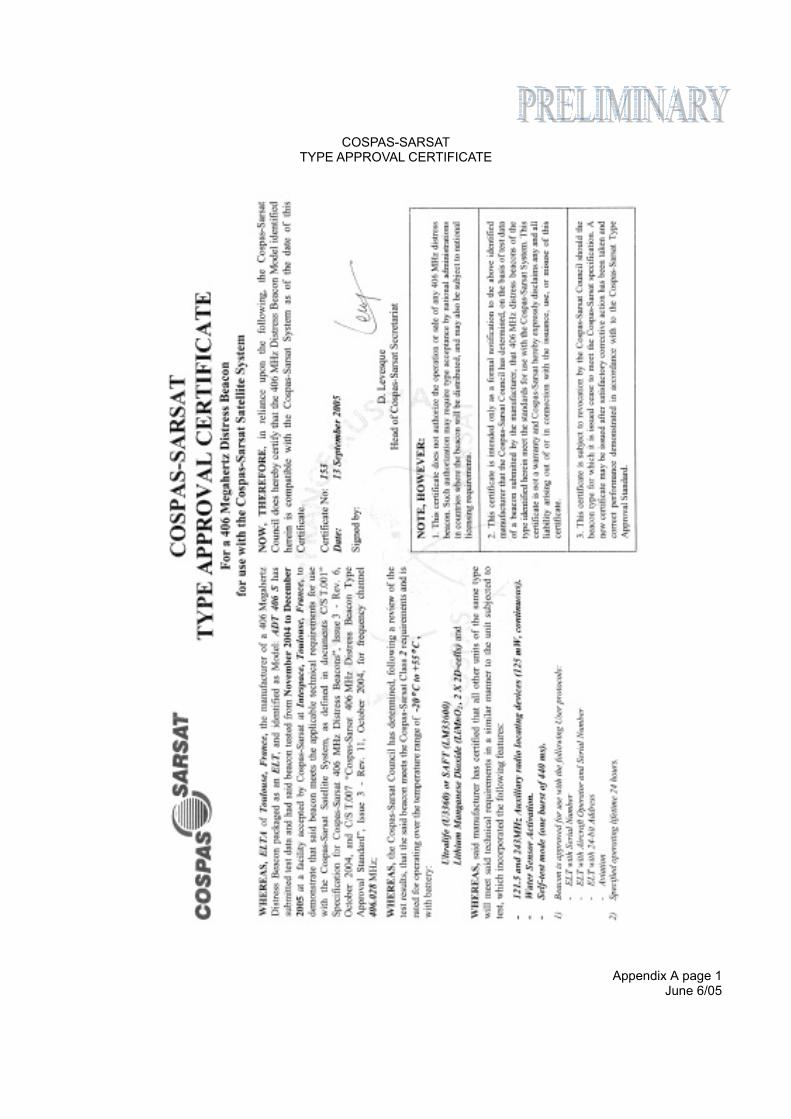
Appendix A page 1 June 6/05
COSPAS-SARSAT TYPE APPROVAL CERTIFICATE
Appendix A page 2 June 6/05
ETSO 2C91a AND ETSO 2C126 APPROVAL

Appendix A page 3 June 6/05
TSO C91a AND TSO C126 APPROVAL
TSO APPROVAL
IS PENDING

Appendix A page 4 June 6/05
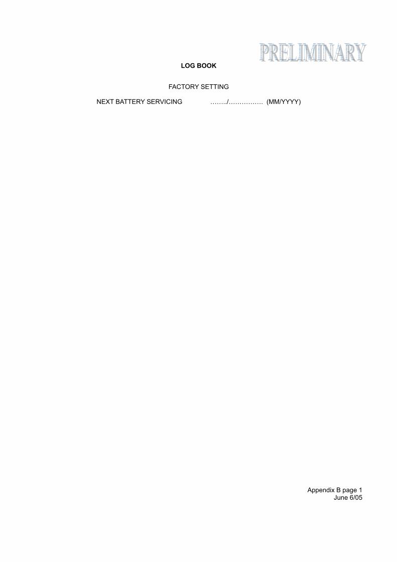
LOG BOOK
Appendix B page 1 June 6/05
FACTORY SETTING
NEXT BATTERY SERVICING ……../……………. (MM/YYYY)

LOG BOOK
Appendix B page 2 June 6/05
FACTORY SETTING
LOG BOOK
Appendix B page 3 June 6/05
ENCODING UPDATE FORM REGISTRATION COUNTRY: ELT SERIAL NUMBER: PROTOCOL: ELT S/N A/C OP-DESIGNATOR + S/N A/C 24 Bit Address A/C REG. MARK TEST C/S 15 HEX: SIMPLIFIED DEC: A/C MSN: A/C OR A/P TYPE: FINAL OPERATOR: CONTACT (PHONE, email…): ISSUED BY: DATE: ……/……/………… (MM/DD/YYYY) SIGNATURE AND STAMP: NOTE : Attach the encoding update sheet issued from the ELTA encoding tool. REGISTRATION COUNTRY: ELT SERIAL NUMBER: PROTOCOL: ELT S/N A/C OP-DESIGNATOR + S/N A/C 24 Bit Address A/C REG. MARK TEST C/S 15 HEX: SIMPLIFIED DEC: A/C MSN: A/C OR A/P TYPE: FINAL OPERATOR: CONTACT (PHONE, email…): ISSUED BY: DATE: ……/……/………… (MM/DD/YYYY) SIGNATURE AND STAMP: NOTE : Attach the encoding update sheet issued from the ELTA encoding tool.
LOG BOOK
Appendix B page 4 June 6/05
ENCODING UPDATE FORM
REGISTRATION COUNTRY: ELT SERIAL NUMBER: PROTOCOL: ELT S/N A/C OP-DESIGNATOR + S/N A/C 24 Bit Address A/C REG. MARK TEST C/S 15 HEX: SIMPLIFIED DEC: A/C MSN: A/C OR A/P TYPE: FINAL OPERATOR: CONTACT (PHONE, email…): ISSUED BY: DATE: ……/……/………… (MM/DD/YYYY) SIGNATURE AND STAMP: NOTE : Attach the encoding update sheet issued from the ELTA encoding tool. REGISTRATION COUNTRY: ELT SERIAL NUMBER: PROTOCOL: ELT S/N A/C OP-DESIGNATOR + S/N A/C 24 Bit Address A/C REG. MARK TEST C/S 15 HEX: SIMPLIFIED DEC: A/C MSN: A/C OR A/P TYPE: FINAL OPERATOR: CONTACT (PHONE, email…): ISSUED BY: DATE: ……/……/………… (MM/DD/YYYY) SIGNATURE AND STAMP: NOTE : Attach the encoding update sheet issued from the ELTA encoding tool.
LOG BOOK
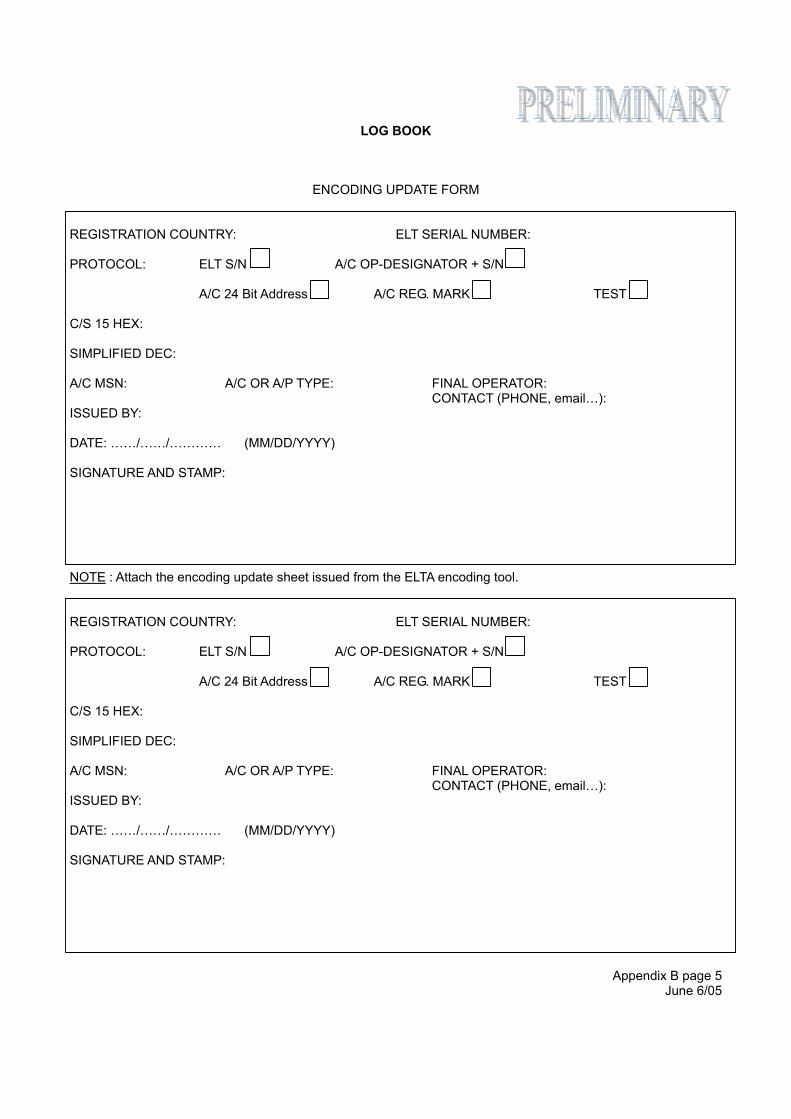
Appendix B page 5 June 6/05
ENCODING UPDATE FORM REGISTRATION COUNTRY: ELT SERIAL NUMBER: PROTOCOL: ELT S/N A/C OP-DESIGNATOR + S/N A/C 24 Bit Address A/C REG. MARK TEST C/S 15 HEX: SIMPLIFIED DEC: A/C MSN: A/C OR A/P TYPE: FINAL OPERATOR: CONTACT (PHONE, email…): ISSUED BY: DATE: ……/……/………… (MM/DD/YYYY) SIGNATURE AND STAMP: NOTE : Attach the encoding update sheet issued from the ELTA encoding tool. REGISTRATION COUNTRY: ELT SERIAL NUMBER: PROTOCOL: ELT S/N A/C OP-DESIGNATOR + S/N A/C 24 Bit Address A/C REG. MARK TEST C/S 15 HEX: SIMPLIFIED DEC: A/C MSN: A/C OR A/P TYPE: FINAL OPERATOR: CONTACT (PHONE, email…): ISSUED BY: DATE: ……/……/………… (MM/DD/YYYY) SIGNATURE AND STAMP:
LOG BOOK
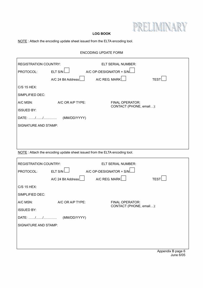
Appendix B page 6 June 6/05
NOTE : Attach the encoding update sheet issued from the ELTA encoding tool.
ENCODING UPDATE FORM REGISTRATION COUNTRY: ELT SERIAL NUMBER: PROTOCOL: ELT S/N A/C OP-DESIGNATOR + S/N A/C 24 Bit Address A/C REG. MARK TEST C/S 15 HEX: SIMPLIFIED DEC: A/C MSN: A/C OR A/P TYPE: FINAL OPERATOR: CONTACT (PHONE, email…): ISSUED BY: DATE: ……/……/………… (MM/DD/YYYY) SIGNATURE AND STAMP: NOTE : Attach the encoding update sheet issued from the ELTA encoding tool. REGISTRATION COUNTRY: ELT SERIAL NUMBER: PROTOCOL: ELT S/N A/C OP-DESIGNATOR + S/N A/C 24 Bit Address A/C REG. MARK TEST C/S 15 HEX: SIMPLIFIED DEC: A/C MSN: A/C OR A/P TYPE: FINAL OPERATOR: CONTACT (PHONE, email…): ISSUED BY: DATE: ……/……/………… (MM/DD/YYYY) SIGNATURE AND STAMP:
LOG BOOK
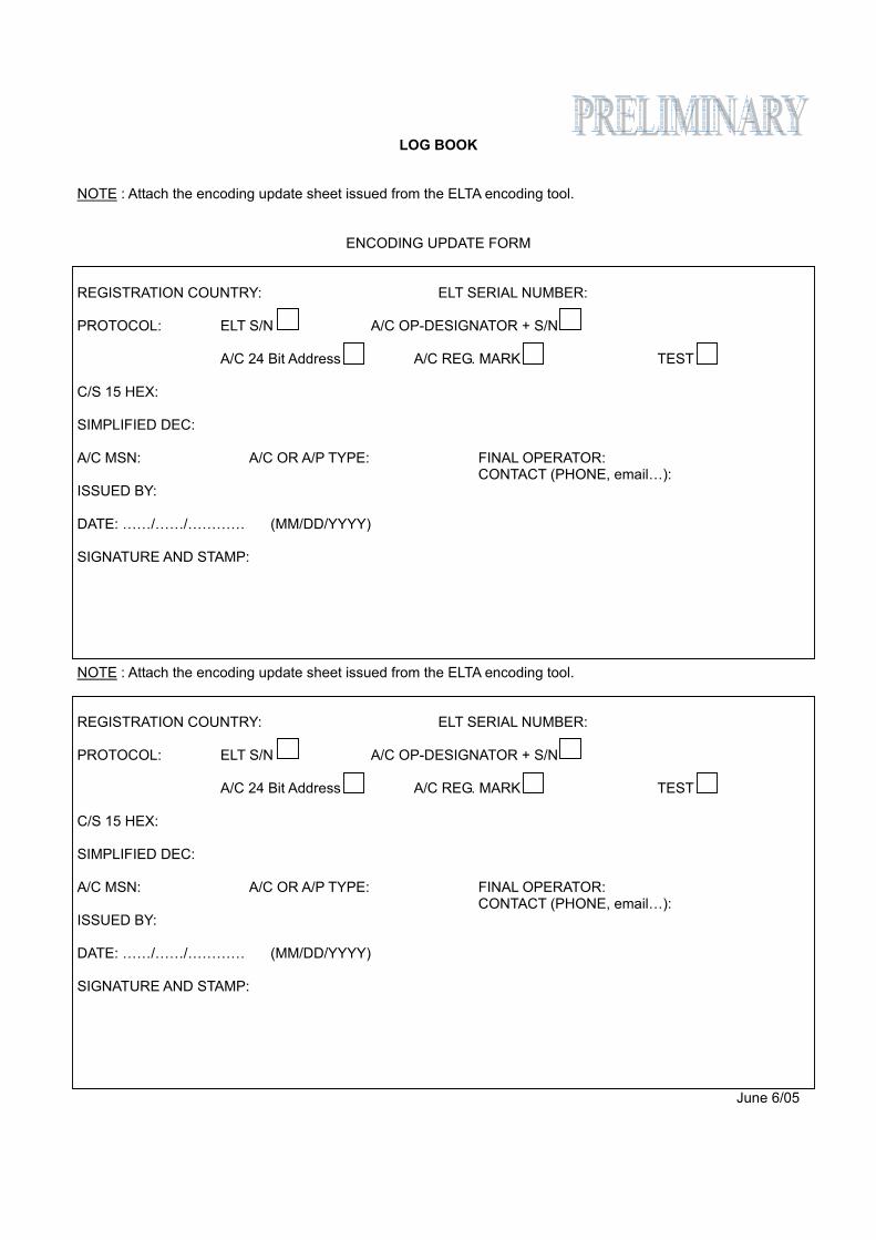
Appendix B page 7 June 6/05
NOTE : Attach the encoding update sheet issued from the ELTA encoding tool.
ENCODING UPDATE FORM REGISTRATION COUNTRY: ELT SERIAL NUMBER: PROTOCOL: ELT S/N A/C OP-DESIGNATOR + S/N A/C 24 Bit Address A/C REG. MARK TEST C/S 15 HEX: SIMPLIFIED DEC: A/C MSN: A/C OR A/P TYPE: FINAL OPERATOR: CONTACT (PHONE, email…): ISSUED BY: DATE: ……/……/………… (MM/DD/YYYY) SIGNATURE AND STAMP: NOTE : Attach the encoding update sheet issued from the ELTA encoding tool. REGISTRATION COUNTRY: ELT SERIAL NUMBER: PROTOCOL: ELT S/N A/C OP-DESIGNATOR + S/N A/C 24 Bit Address A/C REG. MARK TEST C/S 15 HEX: SIMPLIFIED DEC: A/C MSN: A/C OR A/P TYPE: FINAL OPERATOR: CONTACT (PHONE, email…): ISSUED BY: DATE: ……/……/………… (MM/DD/YYYY) SIGNATURE AND STAMP:
LOG BOOK
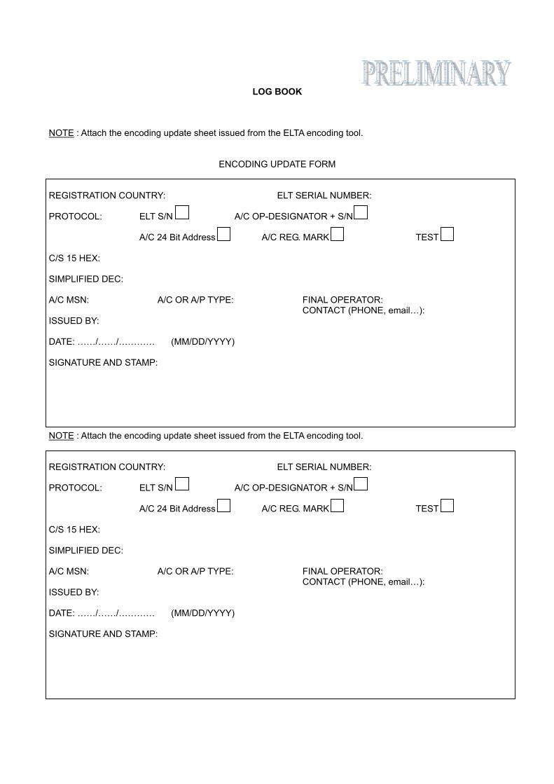
Appendix B page 8 June 6/05
NOTE : Attach the encoding update sheet issued from the ELTA encoding tool.
ENCODING UPDATE FORM REGISTRATION COUNTRY: ELT SERIAL NUMBER: PROTOCOL: ELT S/N A/C OP-DESIGNATOR + S/N A/C 24 Bit Address A/C REG. MARK TEST C/S 15 HEX: SIMPLIFIED DEC: A/C MSN: A/C OR A/P TYPE: FINAL OPERATOR: CONTACT (PHONE, email…): ISSUED BY: DATE: ……/……/………… (MM/DD/YYYY) SIGNATURE AND STAMP: NOTE : Attach the encoding update sheet issued from the ELTA encoding tool. REGISTRATION COUNTRY: ELT SERIAL NUMBER: PROTOCOL: ELT S/N A/C OP-DESIGNATOR + S/N A/C 24 Bit Address A/C REG. MARK TEST C/S 15 HEX: SIMPLIFIED DEC: A/C MSN: A/C OR A/P TYPE: FINAL OPERATOR: CONTACT (PHONE, email…): ISSUED BY: DATE: ……/……/………… (MM/DD/YYYY) SIGNATURE AND STAMP:
LOG BOOK
Appendix B page 9 June 6/05
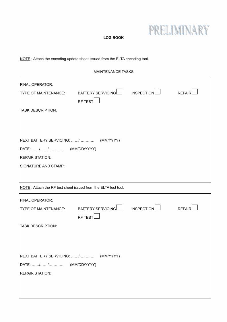
NOTE : Attach the encoding update sheet issued from the ELTA encoding tool.
MAINTENANCE TASKS FINAL OPERATOR: TYPE OF MAINTENANCE: BATTERY SERVICING INSPECTION REPAIR RF TEST TASK DESCRIPTION: NEXT BATTERY SERVICING: ……/………… (MM/YYYY) DATE: ……/……/………… (MM/DD/YYYY) REPAIR STATION: SIGNATURE AND STAMP: NOTE : Attach the RF test sheet issued from the ELTA test tool. FINAL OPERATOR: TYPE OF MAINTENANCE: BATTERY SERVICING INSPECTION REPAIR RF TEST TASK DESCRIPTION: NEXT BATTERY SERVICING: ……/………… (MM/YYYY) DATE: ……/……/………… (MM/DD/YYYY) REPAIR STATION:
LOG BOOK
Appendix B page 10 June 6/05
SIGNATURE AND STAMP: NOTE : Attach the RF test sheet issued from the ELTA test tool.
MAINTENANCE TASKS FINAL OPERATOR: TYPE OF MAINTENANCE: BATTERY SERVICING INSPECTION REPAIR RF TEST TASK DESCRIPTION: NEXT BATTERY SERVICING: ……/………… (MM/YYYY) DATE: ……/……/………… (MM/DD/YYYY) REPAIR STATION: SIGNATURE AND STAMP: NOTE : Attach the RF test sheet issued from the ELTA test tool. FINAL OPERATOR: TYPE OF MAINTENANCE: BATTERY SERVICING INSPECTION REPAIR RF TEST TASK DESCRIPTION: NEXT BATTERY SERVICING: ……/………… (MM/YYYY) DATE: ……/……/………… (MM/DD/YYYY)
LOG BOOK
Appendix B page 11 June 6/05
REPAIR STATION: SIGNATURE AND STAMP: NOTE : Attach the RF test sheet issued from the ELTA test tool.
MAINTENANCE TASKS FINAL OPERATOR: TYPE OF MAINTENANCE: BATTERY SERVICING INSPECTION REPAIR RF TEST TASK DESCRIPTION: NEXT BATTERY SERVICING: ……/………… (MM/YYYY) DATE: ……/……/………… (MM/DD/YYYY) REPAIR STATION: SIGNATURE AND STAMP: NOTE : Attach the RF test sheet issued from the ELTA test tool. FINAL OPERATOR: TYPE OF MAINTENANCE: BATTERY SERVICING INSPECTION REPAIR RF TEST TASK DESCRIPTION: NEXT BATTERY SERVICING: ……/………… (MM/YYYY) DATE: ……/……/………… (MM/DD/YYYY)
LOG BOOK
Appendix B page 12 June 6/05
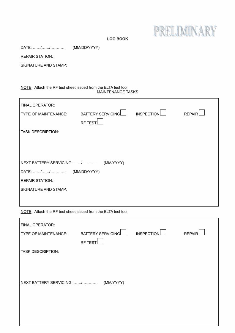
REPAIR STATION: SIGNATURE AND STAMP: NOTE : Attach the RF test sheet issued from the ELTA test tool.
MAINTENANCE TASKS FINAL OPERATOR: TYPE OF MAINTENANCE: BATTERY SERVICING INSPECTION REPAIR RF TEST TASK DESCRIPTION: NEXT BATTERY SERVICING: ……/………… (MM/YYYY) DATE: ……/……/………… (MM/DD/YYYY) REPAIR STATION: SIGNATURE AND STAMP: NOTE : Attach the RF test sheet issued from the ELTA test tool. FINAL OPERATOR: TYPE OF MAINTENANCE: BATTERY SERVICING INSPECTION REPAIR RF TEST TASK DESCRIPTION: NEXT BATTERY SERVICING: ……/………… (MM/YYYY)
LOG BOOK
Appendix B page 13 June 6/05
DATE: ……/……/………… (MM/DD/YYYY) REPAIR STATION: SIGNATURE AND STAMP: NOTE : Attach the RF test sheet issued from the ELTA test tool.
MAINTENANCE TASKS FINAL OPERATOR: TYPE OF MAINTENANCE: BATTERY SERVICING INSPECTION REPAIR RF TEST TASK DESCRIPTION: NEXT BATTERY SERVICING: ……/………… (MM/YYYY) DATE: ……/……/………… (MM/DD/YYYY) REPAIR STATION: SIGNATURE AND STAMP: NOTE : Attach the RF test sheet issued from the ELTA test tool. FINAL OPERATOR: TYPE OF MAINTENANCE: BATTERY SERVICING INSPECTION REPAIR RF TEST TASK DESCRIPTION: NEXT BATTERY SERVICING: ……/………… (MM/YYYY)
LOG BOOK
Appendix B page 14 June 6/05
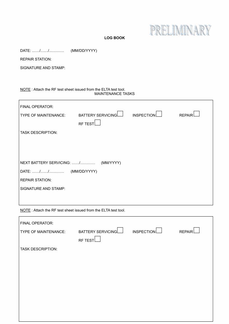
DATE: ……/……/………… (MM/DD/YYYY) REPAIR STATION: SIGNATURE AND STAMP: NOTE : Attach the RF test sheet issued from the ELTA test tool.
MAINTENANCE TASKS FINAL OPERATOR: TYPE OF MAINTENANCE: BATTERY SERVICING INSPECTION REPAIR RF TEST TASK DESCRIPTION: NEXT BATTERY SERVICING: ……/………… (MM/YYYY) DATE: ……/……/………… (MM/DD/YYYY) REPAIR STATION: SIGNATURE AND STAMP: NOTE : Attach the RF test sheet issued from the ELTA test tool. FINAL OPERATOR: TYPE OF MAINTENANCE: BATTERY SERVICING INSPECTION REPAIR RF TEST TASK DESCRIPTION:
LOG BOOK
Appendix B page 15 June 6/05
NEXT BATTERY SERVICING: ……/………… (MM/YYYY) DATE: ……/……/………… (MM/DD/YYYY) REPAIR STATION: SIGNATURE AND STAMP: NOTE : Attach the RF test sheet issued from the ELTA test tool.