advanced index modulation techniques for future wireless ... · ebrahim soujeri manuscript-based...
TRANSCRIPT
Advanced Index Modulation Techniques for Future WirelessNetworks
by
Ebrahim SOUJERI
MANUSCRIPT-BASED THESIS PRESENTED TO ÉCOLE DE
TECHNOLOGIE SUPÉRIEURE IN PARTIAL FULFILLMENT FOR THE
DEGREE OF DOCTOR OF PHILOSOPHY
Ph.D.
MONTREAL, JULY 6, 2018
ÉCOLE DE TECHNOLOGIE SUPÉRIEUREUNIVERSITÉ DU QUÉBEC
Ebrahim Soujeri, 2018

This Creative Commons license allows readers to download this work and share it with others as long as the
author is credited. The content of this work cannot be modified in any way or used commercially.

BOARD OF EXAMINERS
THIS THESIS HAS BEEN EVALUATED
BY THE FOLLOWING BOARD OF EXAMINERS
M. Georges Kaddoum, Thesis Supervisor
Department of Electrical Engineering, École de technologie supérieure
M. Mohamed Cheriet, President of the Board of Examiners
Department of Electrical Engineering, École de technologie supérieure
M. François Gagnon, Member of the Jury
Department of Electrical Engineering, École de technologie supérieure
M. Yousef R. Shayan, External Independent Examiner
Department of Electrical and Computer Engineering, Concordia University
THIS THESIS WAS PRESENTED AND DEFENDED
IN THE PRESENCE OF A BOARD OF EXAMINERS AND THE PUBLIC
ON 13 JUNE 2018
AT ÉCOLE DE TECHNOLOGIE SUPÉRIEURE


ACKNOWLEDGEMENTS
I am especially indebted to Prof. Dr. Georges Kaddoum, who has been so supportive of
my career goals and who worked actively to provide me with the protected academic time to
pursue those goals with his brilliant supervision, continuous support and professional guidance,
without which the achievement of this work would not have been possible. Prof. Dr. Kaddoum
has taught me more than I could ever give him credit for here. He has shown me, by his
example, what a good scientist and person should be.
I am grateful to all of those with whom I have had the pleasure to work during this and other
related projects. Each of the members of my Dissertation Committee has provided me extensive
personal and professional guidance and taught me a great deal about both scientific research
and life in general.
Nobody has been more patient in the pursuit of this project than the members of my family. I
would like to thank my loving and supportive wife, Kokab, and my three wonderful children,
Hamed, Reyhaneh and Isabelle Abrar, who sacrificed a lot and provided unending inspiration.


TECHNIQUES DE MODULATION D’INDEX POUR LES SYSTÈMES DECOMMUNICATION À HAUT DÉBIT DE DONNÉES
Ebrahim SOUJERI
RÉSUMÉ
Dans l’étude de recherche proposée dans cette thèse de doctorat, nous considérons la modu-
lation d’index comme un nouvel outil pour améliorer l’efficacité énergétique et spectrale pour
les réseaux 5G à venir, y compris des réseaux de capteurs sans fil et l’Internet des objets. Dans
ce sens, la modulation spatiale a été proposée par Mesleh et coll. (2008) pour améliorer la
capacité des systèmes sans fil a partiellement atteindre la capacité des Systèmes MIMO mais à
moindre coût, ce qui est, en fait, une technique qui a attiré beaucoup d’attention au cours des
dernières années. En tant que tels, les systèmes SM ont été considérés comme des candidats
possibles pour des systèmes de MIMO de prochaine génération à spectre efficace et à économie
d’énergie, c’est-à-dire à faible consommation. Cependant, la mise en œuvre de la SM est égale-
ment difficile en raison de sa forte dépendance aux caractéristiques du canal, à la corrélation
entre des canaux, aux CSI corrompus et à la nécessité d’avoir l’espacement approprié entre
les antennes. De plus, le SM nécessite plusieurs antennes à l’émetteur, ce qui ajoute un coût
supplémentaire à l’implémentation matérielle. En outre, le nombre de bits mappés dans SM
est limité par la taille physique du dispositif connecté au réseau sans fil où seul un petit nom-
bre d’antennes peut être utilisé. Le temps de commutation gaspillé par RF des commutateurs
d’antenne ajoute à la complexité du problème.
Dans cette thèse, nous étudions les inconvénients du SM dans les articles indiqués ci-dessous,
à savoir « Performance comparison of spatial modulation detectors under channel impairments
» placé à l’annexe à la fin de la thèse puisqu’il s’agit d’un document de conférence, et « Im-
pact of antenna switching time on spatial modulation » qui est mis dans le chapitre 1. Dans
le premier article, nous avons montré que les dégradations de canaux ont des impacts sérieux
sur le BER performances et sur la capacité du système SM et que le SM est trop sensible aux
canaux imparfaits et corrélés. Dans le deuxième article, nous avons démontré que le temps de
commutation défini comme le temps nécessaire par le système pour éteindre une antenne et
activer une autre, qui est une propriété inhérente des commutateurs industriels RF utilisés dans
les systèmes SM, est de l’ordre de nanosecondes et naturellement influence le taux de transmis-
sion des systèmes SM en raison de l’introduction de lacunes systématiques à la transmission
ou des pauses. Compte tenu de la limitation de vitesse des commutateurs RF pratiques lors des
transitions, les technologies basées sur de transition d’antenne comme les systèmes SM sont
plafonnées en termes de performances de débit de données. En effet, le débit effectif de SM
restera l’otage des développements industriels dans le domaine de commutateurs RF. Cela ap-
porte des restrictions aux problèmes de mise en œuvre et de fonctionnement lorsque les débits
de données élevés deviennent une nécessité. Il est démontré par l’assemblage de nos résul-
tats que le temps de commutation Tsw, qui est une condition pour que les transitions entre les
antennes se produisent, dicte restrictions sur le débit de données, la capacité et l’efficacité spec-
trale des systèmes SM. En outre, nous proposons des schémas de modulation d’indexation non

VIII
basés sur matériels comme modulation d’indice de fréquence, modulation chaotique cohérente
et modulation chaotique différentielle non cohérente comme des alternatives potentielles à SM,
qui seraient également adaptés aux réseaux de capteurs sans fil et aux applications de l’Internet
des choses. À cet égard, nous avons proposé trois articles. Le premier article qui représente la
modulation d’indice de fréquence est appelé « Frequency index modulation for low complexity
low energy communication networks » est placé dans le chapitre 2 de cette thèse. Dans cet ar-
ticle, nous explorons un système de communication multi-utilisateur de faible complexité basé
sur la modulation d’indice de fréquence qui convient aux applications de l’Internet des choses
et nous montrons qu’un tel système constituerait un excellent candidat pour les applications de
capteurs sans fil, où il représente une substitution plus simple pour les architectures basées sur
le saut de fréquence, dans lesquelles les houblons portent des morceaux supplémentaires.
Le troisième article qui concerne la modulation chaotique cohérente est appelé « Design of
an initial condition index chaos shift keying modulation » et se trouve au chapitre 3. Dans
cet article, une modulation chaotique cohérente basée sur l’indice de condition initiale est
proposée. Cette conception vise à augmenter l’efficacité spectrale et énergétique aux niveaux
sans précédent. Le schéma proposé exploite les conditions initiales pour générer différentes
séquences chaotiques pour transmettre des extra bits par transmission. Par rapport aux schémas
de modulation rivaux, les résultats obtenus dans le travail proposé montrent un taux de transfert
de données prometteur et une performance compétitive.
Le dernier article utilise un système de décalage-clé chaotique différentiel non cohérent nommé
« Permutation index DCSK modulation technique for secure multi-user high-data-rate commu-
nication systems » qui se trouve dans l’annexe II. Dans cette conception originale, où chaque
trame de données est divisée en deux tranches de temps dans lesquelles le signal chaotique
de référence est envoyé dans le premier intervalle de temps et une réplique permutée de la
référence signal multiplié par le bit de modulation est envoyé dans le deuxième créneau tem-
porel, nous ciblons l’amélioration de sécurité de données, et l’efficacité énergétique et spec-
trale. Dans l’ensemble, compte tenu des exigences élevées en matière de bande passante et
d’efficacité énergétique des systèmes futuristes, les mécanismes d’indexation douce suggérés
par notre étude sont des candidats réussis avec des résultats prometteurs.
Mots-clés: Communications de cinquième génération, réseaux de capteurs sans fil, Internet
des objets, modulation d’indice de fréquence, modulation chaotique de l’indice de condition
initiale

ADVANCED INDEX MODULATION TECHNIQUES FOR FUTURE WIRELESSNETWORKS
Ebrahim SOUJERI
ABSTRACT
In the research study proposed in this Ph.D Thesis, we consider Index Modulation as a novel
tool to enhance energy and spectral efficiencies for upcoming 5G networks, including wire-
less sensor networks and internet of things. In this vein, spatial modulation was proposed to
enhance the capacity of wireless systems to partially achieve the capacity of MIMO systems
but at lower cost, making it a technique that has attracted significant attention over the past
few years. As such, SM schemes have been regarded as possible candidates for spectrum- and
energy-efficient next generation MIMO systems.
However, the implementation of the SM is also challenging because of its heavy dependence
on channel characteristics, channel correlation, corrupted CSI and the need to have adequate
spacing between antennas. Moreover, the SM requires multiple antennas at the transmitter
which adds cost to the hardware implementation. In addition, the number of mapped bits in
SM is limited by the physical size of the wireless device where only small number of antennas
can be used. The switching time wasted by RF antenna switches adds to the complexity of the
issue.
In this Thesis, we study the drawbacks of SM in the articles indicated, namely PerformanceComparison of Spatial Modulation Detectors Under Channel Impairments that is placed in the
Appendix at the end of Thesis as it is a conference paper, and The Impact of Antenna SwitchingTime on Spatial Modulation that is put in Chapter 1.
In the first article, we have shown that channel impairments have serious impacts on the BER
performance and on the capacity of the SM system and that the SM is too sensitive to both
imperfect and correlated channels.
In the second article, we have demonstrated that the switching time defined as the time needed
by the system to turn off an antenna and turn on another one, which is an inherent property
of RF industrial switches used in SM systems, is in the order of nanoseconds and naturally
influences the transmission rate of SM systems because of introducing systematic transmission
gaps or pauses. Given the speed limitation of practical RF switches in performing transitions,
antenna transition-based technologies like SM schemes are capped in terms of data rate perfor-
mance. In fact, the effective data rate of SM will remain hostage to developments in industrial
RF switches. This brings restrictions to the implementation and operation issues when ex-
tremely high data rates become a necessity. It is shown by the assemblage of our results that
the switching time Tsw which is a requirement for transitions between antennas to happen, dic-
tates restrictions on data rate, capacity and spectral efficiency of SM systems.

X
Furthermore, we propose baseband non-hardware-based indexing modulation schemes based
on frequency-index modulation, coherent chaotic modulation and non-coherent differential
chaotic modulation schemes as potential alternatives to SM, that would also fit wireless sensor
networks and internet of things applications. In this regard, we have proposed three articles.
The first article which represents frequency index modulation is called Frequency Index Mod-ulation for Low Complexity Low Energy Communication Networks and is placed in Chapter 2
of this Thesis.
In this article, we explore a low complexity multi-user communication system based on fre-
quency index modulation that suits Internet of Things (IoT) applications and we show that
such a system would constitute an excellent candidate for wireless sensor applications, where
it represents a simpler substitution for frequency-hopping (FH) based architectures, in which
the hops carry extra bits.
The third article which concerns coherent chaotic modulation is called Design of an Initial-Condition Index Chaos Shift Keying Modulation and is located in Chapter 3.
In this article, an initial condition index chaos shift keying modulation is proposed. This design
aims to increase the spectral and energy efficiencies to unprecedented levels. The proposed
scheme exploits the initial conditions to generate different chaotic sequences to convey extra
bits per transmission. In comparison to rival modulation schemes, the results obtained in the
proposed work show a promising data rate boost and a competitive performance.
The last article employs a non-coherent differential chaotic shift-key system named Permuta-tion Index DCSK Modulation Technique for Secure Multi-User High-Data-Rate Communica-tion Systems that is found in the Appendix.
In this original design, where each data frame is divided into two time slots in which the
reference chaotic signal is sent in the first time slot and a permuted replica of the reference
signal multiplied by the modulating bit is sent in the second time slot, we target enhancing data
security, energy and spectral efficiencies.
Overall, in light of the high demands for bandwidth and energy efficiencies of futuristic sys-
tems, the suggested soft indexing mechanisms are successful candidates with promising results.
Keywords: 5G Communications, Wireless Sensor Networks, Internet of Things, Frequency-
Index Modulation, Initial Condition-Index Chaotic Modulation

TABLE OF CONTENTS
Page
INTRODUCTION . . . . . . . . . . . . . . . . . . . . . . . . . . . . . . . . . . . . . . . . . . . . . . . . . . . . . . . . . . . . . . . . . . . . . . . . . . . . . . . . 1
CHAPTER 1 THE IMPACT OF ANTENNA SWITCHING TIME ON
SPATIAL MODULATION . . . . . . . . . . . . . . . . . . . . . . . . . . . . . . . . . . . . . . . . . . . . . . . . . . 21
1.1 Introduction . . . . . . . . . . . . . . . . . . . . . . . . . . . . . . . . . . . . . . . . . . . . . . . . . . . . . . . . . . . . . . . . . . . . . . . . . . . . . . 21
1.2 System Model . . . . . . . . . . . . . . . . . . . . . . . . . . . . . . . . . . . . . . . . . . . . . . . . . . . . . . . . . . . . . . . . . . . . . . . . . . . 23
1.3 Analytical View . . . . . . . . . . . . . . . . . . . . . . . . . . . . . . . . . . . . . . . . . . . . . . . . . . . . . . . . . . . . . . . . . . . . . . . . . 24
1.3.1 Effective SM Capacity . . . . . . . . . . . . . . . . . . . . . . . . . . . . . . . . . . . . . . . . . . . . . . . . . . . . . . . . 25
1.3.2 Restrictions on β . . . . . . . . . . . . . . . . . . . . . . . . . . . . . . . . . . . . . . . . . . . . . . . . . . . . . . . . . . . . . . 26
1.3.3 Spectral Efficiency . . . . . . . . . . . . . . . . . . . . . . . . . . . . . . . . . . . . . . . . . . . . . . . . . . . . . . . . . . . . 27
1.4 Discussions and Numerical Results . . . . . . . . . . . . . . . . . . . . . . . . . . . . . . . . . . . . . . . . . . . . . . . . . . . . 28
1.5 Conclusions . . . . . . . . . . . . . . . . . . . . . . . . . . . . . . . . . . . . . . . . . . . . . . . . . . . . . . . . . . . . . . . . . . . . . . . . . . . . . . 31
CHAPTER 2 FREQUENCY INDEX MODULATION FOR LOW COMPLEXITY
LOW ENERGY COMMUNICATION NETWORKS . . . . . . . . . . . . . . . . . . . . . . 33
2.1 Introduction . . . . . . . . . . . . . . . . . . . . . . . . . . . . . . . . . . . . . . . . . . . . . . . . . . . . . . . . . . . . . . . . . . . . . . . . . . . . . . 34
2.2 System Model . . . . . . . . . . . . . . . . . . . . . . . . . . . . . . . . . . . . . . . . . . . . . . . . . . . . . . . . . . . . . . . . . . . . . . . . . . . 37
2.2.1 The Transmitter . . . . . . . . . . . . . . . . . . . . . . . . . . . . . . . . . . . . . . . . . . . . . . . . . . . . . . . . . . . . . . . 37
2.2.2 Total Mapped Bits pT . . . . . . . . . . . . . . . . . . . . . . . . . . . . . . . . . . . . . . . . . . . . . . . . . . . . . . . . . 38
2.2.3 The Receiver . . . . . . . . . . . . . . . . . . . . . . . . . . . . . . . . . . . . . . . . . . . . . . . . . . . . . . . . . . . . . . . . . . 41
2.3 FIM Performance Analysis . . . . . . . . . . . . . . . . . . . . . . . . . . . . . . . . . . . . . . . . . . . . . . . . . . . . . . . . . . . . . 42
2.3.1 BER Analysis of FIM . . . . . . . . . . . . . . . . . . . . . . . . . . . . . . . . . . . . . . . . . . . . . . . . . . . . . . . . . 42
2.3.2 Erroneous Active Subcarrier Index Detection Ped . . . . . . . . . . . . . . . . . . . . . . . . . . . 44
2.3.3 BER of Mapped and Modulated Bits . . . . . . . . . . . . . . . . . . . . . . . . . . . . . . . . . . . . . . . . 47
2.4 Energy Efficiency, PAPR and Complexity . . . . . . . . . . . . . . . . . . . . . . . . . . . . . . . . . . . . . . . . . . . . . 48
2.4.1 Energy Efficiency . . . . . . . . . . . . . . . . . . . . . . . . . . . . . . . . . . . . . . . . . . . . . . . . . . . . . . . . . . . . . 48
2.4.2 PAPR Analysis . . . . . . . . . . . . . . . . . . . . . . . . . . . . . . . . . . . . . . . . . . . . . . . . . . . . . . . . . . . . . . . . 49
2.4.3 System Complexity . . . . . . . . . . . . . . . . . . . . . . . . . . . . . . . . . . . . . . . . . . . . . . . . . . . . . . . . . . . 50
2.5 Simulation Results . . . . . . . . . . . . . . . . . . . . . . . . . . . . . . . . . . . . . . . . . . . . . . . . . . . . . . . . . . . . . . . . . . . . . . 51
2.5.1 Performance of FIM . . . . . . . . . . . . . . . . . . . . . . . . . . . . . . . . . . . . . . . . . . . . . . . . . . . . . . . . . . 52
2.5.2 Performance Comparison with SM and OFDM-IM Systems . . . . . . . . . . . . . . . 54
2.5.3 Energy Efficiency, PAPR and Complexity Analysis . . . . . . . . . . . . . . . . . . . . . . . . 56
2.5.3.1 Energy Efficiency and PAPR Analysis . . . . . . . . . . . . . . . . . . . . . . . . . . . 56
2.5.3.2 System Complexity . . . . . . . . . . . . . . . . . . . . . . . . . . . . . . . . . . . . . . . . . . . . . . . 58
2.6 Conclusions . . . . . . . . . . . . . . . . . . . . . . . . . . . . . . . . . . . . . . . . . . . . . . . . . . . . . . . . . . . . . . . . . . . . . . . . . . . . . . 59
CHAPTER 3 DESIGN OF AN INITIAL-CONDITION INDEX CHAOS
SHIFT KEYING MODULATION . . . . . . . . . . . . . . . . . . . . . . . . . . . . . . . . . . . . . . . . . . 61
3.1 Introduction . . . . . . . . . . . . . . . . . . . . . . . . . . . . . . . . . . . . . . . . . . . . . . . . . . . . . . . . . . . . . . . . . . . . . . . . . . . . . . 62
3.2 ICI-CSK system model . . . . . . . . . . . . . . . . . . . . . . . . . . . . . . . . . . . . . . . . . . . . . . . . . . . . . . . . . . . . . . . . . 64
XII
3.3 Probability of Error for Mapped Bits . . . . . . . . . . . . . . . . . . . . . . . . . . . . . . . . . . . . . . . . . . . . . . . . . . . 66
3.4 BER Performance Analysis of the ICI-CSK System . . . . . . . . . . . . . . . . . . . . . . . . . . . . . . . . . 66
3.5 Simulation and Evaluation . . . . . . . . . . . . . . . . . . . . . . . . . . . . . . . . . . . . . . . . . . . . . . . . . . . . . . . . . . . . . . 67
3.6 Conclusions . . . . . . . . . . . . . . . . . . . . . . . . . . . . . . . . . . . . . . . . . . . . . . . . . . . . . . . . . . . . . . . . . . . . . . . . . . . . . . 69
CONCLUSION AND RECOMMENDATIONS . . . . . . . . . . . . . . . . . . . . . . . . . . . . . . . . . . . . . . . . . . . . . . . 71
APPENDIX I PERFORMANCE COMPARISON OF SPATIAL MODULATION
DETECTORS UNDER CHANNEL IMPAIRMENTS . . . . . . . . . . . . . . . . . . . . . 77
APPENDIX II PERMUTATION INDEX DCSK MODULATION TECHNIQUE
FOR SECURE MULTI-USER HIGH-DATA-RATE COMMUNICATION
SYSTEMS . . . . . . . . . . . . . . . . . . . . . . . . . . . . . . . . . . . . . . . . . . . . . . . . . . . . . . . . . . . . . . . . . . . . 93
BIBLIOGRAPHY . . . . . . . . . . . . . . . . . . . . . . . . . . . . . . . . . . . . . . . . . . . . . . . . . . . . . . . . . . . . . . . . . . . . . . . . . . . . . .131

LIST OF TABLES
Page
Table 1.1 Capacity and switching parameters vs. antenna setup . . . . . . . . . . . . . . . . . . . . . . . . . 30
Table 2.1 FIM transmits a total of pT mapped bits using
NB number of sub-bands with N frequencies each . . . . . . . . . . . . . . . . . . . . . . . . . . . . . 39
Table 2.2 Comparison, OFDM, OFDM-IM and FIM systems for the
conveyance of 3 bits per transmission . . . . . . . . . . . . . . . . . . . . . . . . . . . . . . . . . . . . . . . . . . . 59


LIST OF FIGURES
Page
Figure 0.1 3-D signal constellation for SM systems with M = 4 and Nt = 4 . . . . . . . . . . . . . 5
Figure 0.2 The concept of switching time and its influence on the system
performance . . . . . . . . . . . . . . . . . . . . . . . . . . . . . . . . . . . . . . . . . . . . . . . . . . . . . . . . . . . . . . . . . . . . . . 8
Figure 0.3 CIM-SS system model: (a) Transmitter (b) In phase receiver
structure Taken from Kaddoum et al. (2015b) . . . . . . . . . . . . . . . . . . . . . . . . . . . . . . . . 10
Figure 1.1 Block diagram of the SM transmitter . . . . . . . . . . . . . . . . . . . . . . . . . . . . . . . . . . . . . . . . . 23
Figure 1.2 The effective SM data rate versus SM symbol rate . . . . . . . . . . . . . . . . . . . . . . . . . . . 29
Figure 1.3 Capacities of MIMO, SM and SIMO systems . . . . . . . . . . . . . . . . . . . . . . . . . . . . . . . . . 30
Figure 1.4 SM Spectral efficiency η versus β for various values of Nt . . . . . . . . . . . . . . . . . . 31
Figure 2.1 Block diagram of the general structure of FIM communication
system: a) the transmitter, and b) the receiver . . . . . . . . . . . . . . . . . . . . . . . . . . . . . . . . 40
Figure 2.2 A given FIM system with 4 subcarriers. In the illustration, the
transmitter has indexed the message 01 and transmits the rest of
the message via the subcarrier f2 only . . . . . . . . . . . . . . . . . . . . . . . . . . . . . . . . . . . . . . . . . 41
Figure 2.3 Performance of the proposed system with various values of M and
N that facilitate the conveyance of 7 bits per transmission . . . . . . . . . . . . . . . . . . . 53
Figure 2.4 Performance of the proposed FIM system with various modulation
order M for N = 4 subcarriers per sub-band. . . . . . . . . . . . . . . . . . . . . . . . . . . . . . . . . . . 53
Figure 2.5 Performance of the proposed FIM system for various subcarriers
per sub-band and a modulation order of M = 8 . . . . . . . . . . . . . . . . . . . . . . . . . . . . . . . 54
Figure 2.6 Performance of FIM in comparison to SM and OFDM-IM for the
transmission of a total of 3 bits (mapped and modulated) . . . . . . . . . . . . . . . . . . . . 55
Figure 2.7 CCDFs of the PAPR of the proposed FIM system with
complementing NB and N combinations for NFIM = 64 . . . . . . . . . . . . . . . . . . . . . . 57
Figure 2.8 Complexity comparison of the proposed FIM, conventional OFDM
and OFDM-IM(n,k) systems using a number of subband NB = 1
and FFT-length NFIM = NNB . . . . . . . . . . . . . . . . . . . . . . . . . . . . . . . . . . . . . . . . . . . . . . . . . . . 59

XVI
Figure 3.1 A general scheme of the proposed ICI-CSK architecture: (a)
transmitter and (b) receiver . . . . . . . . . . . . . . . . . . . . . . . . . . . . . . . . . . . . . . . . . . . . . . . . . . . . . 64
Figure 3.2 BER performance of ICI-CSK compared to SM and M-ary PSK for
the transmission of ptot = 4,6 bits. CSK sequence length β = 128 . . . . . . . . . . 68

LIST OF ABREVIATIONS
AWGN Additive White Gaussian Noise
BER Bit Error Rate
BPSK Binary Phase Shift Keying
BS Base Station
CDF Cumulative Density Function
CDMA Code Division Multiple-Access
CIM Code Index Modulation
CM Channel Model
CMOS Complementary Metal–Oxide–Semiconductor
CP Cyclic Prefix
CS Code Shifted
CSD Chaotic Symbolic Dynamic
CSI Channel State Information
DBR Data Energy to Bit Energy Ratio
DCSK Differential Chaos Shift Keying
DF Decode and Forward
ESIM Enhanced Subcarrier Index Modulation
ETS École de Technologie Supérieure
FBMC Filter Bank Multicarrier

XVIII
FFT Fast Fourier Transform
FH Frequency Hopping
FIM Frequency Index Modulation
FM Frequency Modulation
FPGA Field-Programmable Gate Array
IAS Inter-Antenna Synchronization
ICI-CSK Initial Condition-Index Chaotic Shift Keying
ICT Information and Communication Technology
IEEE Institute of Electrical and Electronics Engineers
IM Index Modulation
IoT Internet of Things
ISM Industrial Scientific and Medical
LED Light Emitting Diode
LLR Log-Likelihood Ratio
LPI Low Probability of Interception
MA Multiple-Access
MEMS Micro Electro Mechanical Systems
MFSK Multiple Frequency-Shift Keying
MIMO Multiple-Input Multiple-Output
MISO Multiple-Input Single-Output

XIX
ML Maximum Likelihood
MMSE Minimum Mean Square Error
MQAM M−ary Quadrature Amplitude Modulation
Msps Mega symbols per second
MU Multiuser
NR Noise Reduction
OD Optimum Detection
OFDM Orthogonal Frequency Division Multiplexing
OM Orthogonal Multilevel
OQPSK Offset Quadrature Phase Shift Keying
PAPR Peak-to-Average Power Ratio
PDF Probability Density Function
PI Permutation Index
PPP Public Private Partnership
QCSK Quadrature Chaos Shift Keying
QPSK Quadrature Phase Shift Keying
RCG Repeated Chaotic Generators
RF Radio Frequency
SER Symbol Error Rate
SIM Subcarrier Index Modulation

XX
SIMO Single-Input Multiple-Output
SISO Single-Input Single-Output
SLED Square-Law Envelope Detector
SM Spatial Modulation
SME Small and Medium Enterprise
SS Spread Spectrum
SSK Space-Shift Keying
STBC Space-Time Block Codes
TR Transmitted Reference
UWB Ultra Wide Band
WBAN Wireless Body Area Networks
WSN Wireless Sensor Networks
ZF Zero Forcing
ZMCG Zero-Mean Complex Gaussian

INTRODUCTION
The fifth generation (5G) Infrastructure Public Private Partnership known as the 5G-PPP is a
joint initiative between the European Commission and European information and communica-
tions technology (ICT) manufacturers, telecommunications operators, service providers, small
or medium-sized enterprises (SMEs) and researcher Institutions. The 5G-PPP is now in its sec-
ond phase where 21 new projects were recently launched in Brussels in 2017. The 5G PPP will
deliver solutions, architectures, technologies and standards for the ubiquitous next generation
communication infrastructures of the coming decade across the globe. The challenge for the
5G Public Private Partnership (5G PPP) is to secure leadership in the particular areas where
there is potential for creating new markets such as smart cities, e-health, intelligent transport,
education or entertainment and media. The 5G PPP initiative will reinforce the success of the
telecommunications industry in global markets and open new innovation opportunities. Ac-
cording to European Commission & European ICT Industry (2014), it will open a platform
that helps reaching the common goal to maintain and strengthen the global technological lead.
The key challenges for the 5G Infrastructure PPP may be summarized as
- Providing 1000 times higher wireless area capacity and more varied service capabilities
compared to 2010;
- Saving up to 90% of energy per service provided. The main focus will be in mobile commu-
nication networks where the dominating energy consumption comes from the radio access
network;
- Reducing the average service creation time cycle from 90 hours to 90 minutes.
- Creating a secure, reliable and dependable Internet with a zero perceived downtime for
services provision;

2
- Facilitating very dense deployments of wireless communication links to connect over 7
trillion wireless devices serving over 7 billion people;
- Ensuring for everyone and everywhere the access to a wider panel of services and applica-
tions at lower cost.
0.1 Modulation for 5G Wireless Communications
Concerning the physical layer and the modulation techniques involved therein, Orthogonal
Frequency Division Multiplexing (OFDM) is known to be the main platform for 5G wireless
communications modulation. But as OFDM has a set of drawbacks like the need to a cyclic
prefix (CP), side-lobe frequencies, peak to average power ratio (PAPR) and high sensitivity to
carrier frequency offsets, a new technique called Filter Bank Multi-Carrier (FBMC) has been
developed to compensate the deficiencies of OFDM and to offer ways of overcoming the known
limitations of OFDM of reduced spectral efficiency and strict synchronization requirements.
These advantages have led it to being considered as one of the modulation techniques for 5G
communication systems Schellmann et al. (2014); Wunder et al. (2014). Note that FBMC is
a development of OFDM, which uses banks of filters that are implemented, typically using
digital signal processing techniques. Furthermore, when carriers are modulated in an OFDM
system, side-lobes spread out either side. With a filter bank system, the filters are used to
remove these side-lobes and much cleaner carriers are obtained. FBMC is, however, more
complex than OFDM and less flexible for multiple-input multiple-output (MIMO) applications.
In addition, OFDM has been around for more than 3 decades and is already incorporated into
many platforms in various applications, therefore, any shift to a newer technology like FBMC
will need time.

3
0.2 Index Modulation
Since 5G wireless networks have drawn great attention over the past few years Andrews et al.
(2014), Wang et al. (2014) as the wireless infrastructure for the future, research is ongoing to
further enhance this yet to-be implemented technology in terms of bandwidth, data rate and la-
tency. Since almost everything will be connected to the internet in what is known as the Internet
of Things (IoT) Weber & Weber (2010), it is necessary to develop novel spectrum and energy
efficient physical layer techniques for 5G wireless communication networks. Some techniques
such as massive MIMO systems, millimetre wave (mmWave) communications and flexible
waveform designs have already been developed; however, research community is still working
to propose new and more influential physical layer solutions toward 5G wireless networks.
The Index Modulation (IM) technique, which considers innovative ways to convey extra in-
formation bits compared to traditional communication systems, appears as a competitive can-
didate for next generation wireless networks due to the attractive features it offers in terms of
spectral and energy efficiencies as well as hardware simplicity. The interest in IM techniques
has grown in the past few years as it augments energy and spectrum efficiencies while remain-
ing simple and being possible to merge with theoretically any digital modulation technique.
IM accommodates substitute manners to transfer extra information compared to classical dig-
ital modulation schemes that depend on amplitude, phase or frequency of a sinusoidal carrier
signal for communication.
In fact, IM schemes map extra information bits by altering the on/off status of an entity in the
communication system into which it is merged, such as transmit antennas, subcarriers, radio
frequency (RF) mirrors, transmit light emitting diodes (LEDs), relays, modulation types, time
slots, precoder matrices, dispersion matrices, spreading codes, signal powers, etc. Brief, IM
establishes totally novel dimensions for data transmission.

4
In IM, a considerable part of the outgoing bits are inherently transmitted, so their transmission
energy is saved and transferred to the actually –physically– transmitted bits, which results
in an improved error performance compared to classical schemes that utilise the same total
transmission energy. That is to say, IM schemes convey extra information in an energy-efficient
fashion.
As IM suggests new dimensions for conveying digital information, the spectral efficiency of the
considered communication system can be effectively enhanced without increasing hardware
complexity. In the following sections, we will have a glance at spatial modulation, code index
modulation, frequency index modulation and initial-condition chaos shift keying modulation
as examples of concern of IM.
0.3 Spatial Modulation
SM is a technique in which indices of the transmit antennas of a MIMO architecture are used for
conveying additional information, and is indeed one of the earliest applications of IM, where
it represents a novel method to transmit information by means of the indices of the transmit
antennas of a MIMO architecture in addition to the conventional M−ary signal constellations.
In fact, SM appeared in some works like Chau et al. (2001) and Haas et al. (2002) for the
first time but under different names and terminologies, however, the term spatial modulation is
utilised for the first time in the studies of Ganesan et al. (2006) and Mesleh et al. (2006a).
To be specific, two information-carrying units exist in SM, the indices of the available trans-
mit antennas and the M−ary constellation symbols. For each transmission interval, a total of
log2(Nt)+ log2(M) outgoing bits enter the transmitter of an SM system, where Nt is the num-
ber of antennas in the transmit antenna array and M is the modulation order. To provide some
detail, the first log2(M) bits of the outgoing bit sequence are used to modulate the phase and/or
amplitude of a carrier signal, while the remaining log2(Nt) bits of the outgoing bit sequence

5
are considered for the selection of the index of the active transmit antenna that will be turned
on to perform the transmission of the corresponding modulated signal. A 3-dimensional con-
stellation diagram of SM with Nt = 4 antennae and Quadrature Phase Shift Keying (QPSK)
constellation M = 4 is shown in Figure 0.1.
Figure 0.1 3-D signal constellation for SM systems with M = 4 and Nt = 4
Note that a simpler implementation of the SM that relies only on antenna indices and does not
incorporate any signal modulation that is known as space-shift keying (SSK) is investigated
and developed by Jeganathan et al. (2008b), Jeganathan et al. (2009). Compared to SM, SSK
requires neither in-phase and quadrature (IQ) modulation nor pulse shaping, and thus, has a
simpler form and less complexity.
6
0.3.1 SM Receiver
The receiver of the SM scheme has to deal with the following two major tasks: detection of
the active transmit antenna for the demodulation of IM bits and detection of the data symbol
transmitted over the activated transmit antenna for the demodulation of the bits mapped to
the M−ary signal constellation. As a matter of fact, the optimum ML detector of SM has to
jointly search over all transmit antennas and constellation symbols to decode both of the bits.
Although the suboptimal detector can obtain a significant complexity reduction for increasing
number of transmit antennas and higher order constellations, its error performance is consid-
erably worse than that of the ML detector. Therefore, the implementation of the suboptimal
detector can be problematic for critical applications that require a low error rate. Addition-
ally, the sparse structure of SM transmission vectors paves the way for the implementation of
near/sub-optimal low-complexity detection methods for SM systems such as matched filter-
based detection Tang et al. (2013) and compressed sensing (CS)-based detection Yu et al.
(2012).
0.3.2 Features and Drawbacks of SM
In light of the above discussion on the concept of SM, MIMO systems employing SM provide
attractive advantages over their traditional counterparts Di Renzo et al. (2016). The main
advantages of SM over classical MIMO systems could be summarized as Basar et al. (2017):
- High spectral efficiency: The spectral efficiency of SM is superior to that of traditional
single-input single-output (SISO) systems as well as orthogonal space-time block codes
(STBCs) due to indexing the transmit antenna number as a supplementary approach of
ferrying extra information;
7
- High energy efficiency: The SM transmitter power consumption is unconnected to the num-
ber of transmit antennas, while the information can still be transferred via these antennas.
In fact, SM may be regarded as a green and energy-efficient MIMO technology as it may
deploy a transmission system without requiring additional transmission energy but by using
a higher number of transmit antennas;
- Simple transceiver design: One RF chain is sufficient for the SM scheme compared to
MIMO where many are required, as SM activates a single antenna during a given transmis-
sion;
- Elimination of Inter-antenna synchronization (IAS) and inter-channel interference.
While the SM scheme has the aforementioned appealing advantages, it also has some disad-
vantages, which are summarized as follows:
- It is mainly solely suitable for base stations of wireless networks, where space is abundant to
host multiple antennas. This is because smaller devices such as cell phones do not have the
necessary physical space to provide, especially considering that a spacing of λ/2 between
antennas must be respected, where λ is the transmission wavelength;
- SM is also not applicable to sensor networks and IoT devices as most these devices are tiny
and may not have the physical space to handle multiple antennas;
- The spectral efficiency of SM increases logarithmically with Nt ;
- The channel coefficients of different transmit antennas have to be sufficiently different for
an SM scheme to operate effectively. In other words, SM requires rich scattering environ-
ments to ensure better error performance. This requirement is not guaranteed and renders
SM impractical;
8
- The decoding complexity of the SM receiver, in terms of the total number of real multipli-
cations, grows linearly with the product of the constellation size and the number of transmit
antennas;
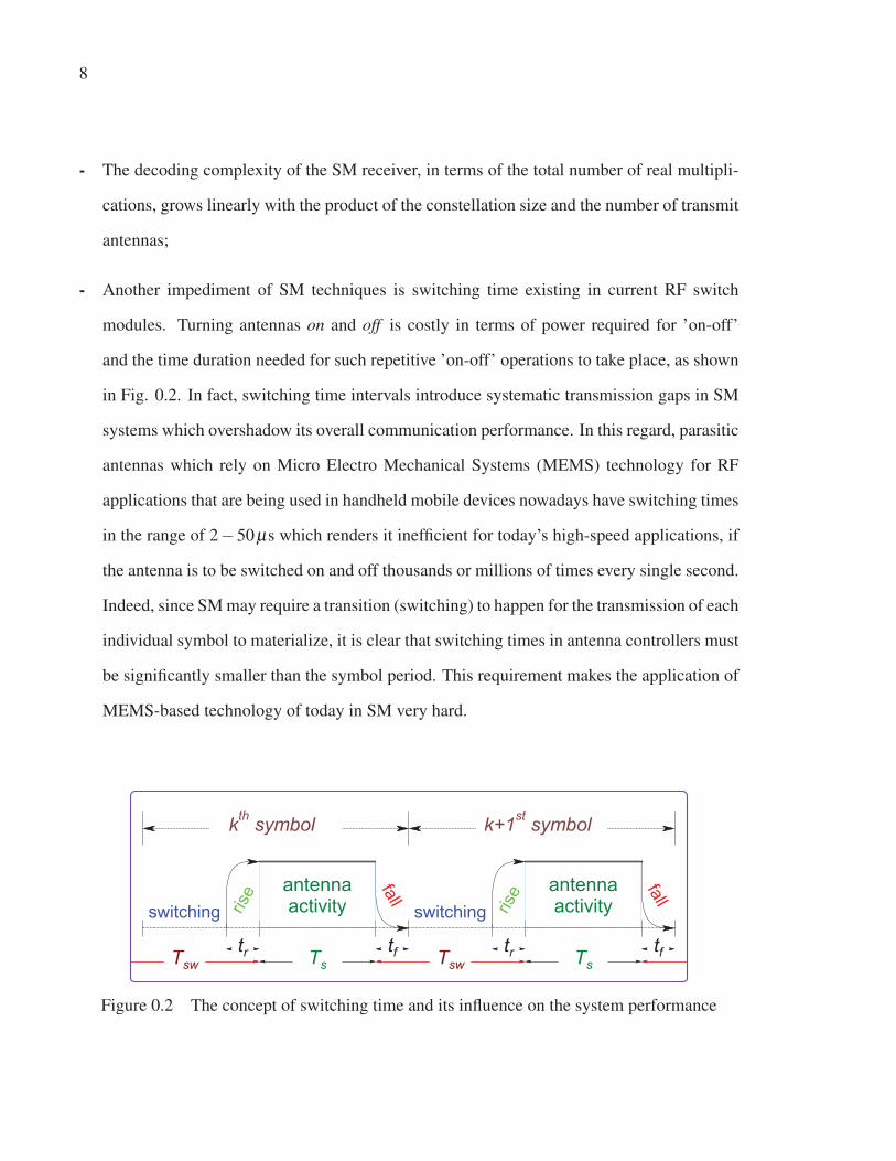
- Another impediment of SM techniques is switching time existing in current RF switch
modules. Turning antennas on and off is costly in terms of power required for ’on-off’
and the time duration needed for such repetitive ’on-off’ operations to take place, as shown
in Fig. 0.2. In fact, switching time intervals introduce systematic transmission gaps in SM
systems which overshadow its overall communication performance. In this regard, parasitic
antennas which rely on Micro Electro Mechanical Systems (MEMS) technology for RF
applications that are being used in handheld mobile devices nowadays have switching times
in the range of 2−50μs which renders it inefficient for today’s high-speed applications, if
the antenna is to be switched on and off thousands or millions of times every single second.
Indeed, since SM may require a transition (switching) to happen for the transmission of each
individual symbol to materialize, it is clear that switching times in antenna controllers must
be significantly smaller than the symbol period. This requirement makes the application of
MEMS-based technology of today in SM very hard.
Figure 0.2 The concept of switching time and its influence on the system performance

9
Considering the advantages and disadvantages of SM systems mentioned above, we may con-
clude that SM scheme provides an interesting trade-off among encoding/decoding complexity,
spectral efficiency, and error performance, however, further technological advancement espe-
cially in RF switching techniques is needed before its full implementation.
0.4 Code Index Modulation
A new technique that uses the index modulation domain is developed in Kaddoum et al.
(2015b) where the spreading code domain is used as an indexing parameter in order to in-
crease the data rate without adding extra computations complexity to the system. This scheme,
which is called code index modulation-spread spectrum (CIM-SS), may also be integrated with
MIMO or SM systems to achieve higher throughput. CIM-SS uses spreading codes to map
additional outgoing data in conjunction with constellation symbols. A system model incorpo-
rating the CIM-SS transmitter and receiver structures extracted from Kaddoum et al. (2015b)
is shown in Fig. 0.3.
The basic form of CIM-SS considers the outgoing data in pairs, where for each pair of bits, one
bit chooses a spreading code from a pre-assigned set of codes, and the other bit is spread by the
selected code. At the receiver, the spreading code is first detected which allows the recovery
of the mapped bit then the transmitted bit is demodulated via despreading. With this elegant
scheme, only half of the bits are physically transmitted over the channel and the other half
are mapped into spreading codes. Consequently, CIM-SS increases throughput and decreases
energy consumption while retaining the system easy to implement. Furthermore, the gains of
the spread spectrum modulation are maintained in the proposed CIM-SS scheme.
In fact, CIM-SS is among the earliest soft-indexing techniques that appeared as a rival for
the hardware-based SM technique. A generalized form of this technique which uses M−ary
constellation instead of a binary one is developed in Kaddoum et al. (2016b).

10
Figure 0.3 CIM-SS system model: (a) Transmitter (b) In phase receiver structure
Taken from Kaddoum et al. (2015b)
0.5 Frequency Index Modulation
Within the context of soft-index modulation, subcarrier index modulation (SIM) scheme has
been proposed in Abu-Alhiga & Haas (2009) where it has been merged with orthogonal fre-
quency division multiplexing (OFDM) to constitute SIM-OFDM. Moreover, enhanced subcar-
rier index modulation (ESIM) has been proposed to avoid the propagation of error by replacing
the concept of majority counting by a simpler method in which a pair of off-on or on-off subcar-
riers is used to represent a single bit Tsonev et al. (2011), however, the fact that two subcarriers
are used to transmit a single bit doubles the required bandwidth necessary for transmission in
this method.

11
Eventually, a transmission scheme called OFDM with index modulation (OFDM-IM) is pro-
posed Basar et al. (2013). In this scheme, information is conveyed not only by M-ary signal
constellations as in classical OFDM, but also by the indices of the subcarriers, which are ac-
tivated according to the incoming information bits. But from the practical point of view, the
implementation of this scheme is difficult as it relies on the maximum likelihood (ML) de-
tection that requires heavy computing charges as it needs to search over all the possibilities
(subcarrier combinations) within a bandwidth. This is costly as it makes a joint search over all
possibilities Basar (2015) and is impractical for large combination values due to its exponen-
tially growing decoding complexity Basar et al. (2013), which makes it unsuitable for WSN
applications. Furthermore, the Log-Likelihood Ratio (LLR) detection strategy is another de-
tection method proposed for this scheme for high number of subcarriers, but this detector may
produce an undefined set of active indices not at all included in the original mapping table
Basar et al. (2013).
In the work of Soujeri et al. (2017), a modified frequency index modulation (FIM) scheme
that is simpler than the approach of Basar et al. (2013) is introduced. This system has a lower
complexity compared to OFDM-IM, lower power consumption profile and does not sacrifice
data rate as it makes use of the frequency hops in a smart and wise way. As the proposed system
does not use all of the available subcarriers, it will also enjoy inter-carrier interference -free
transmission while it allows the transmission of additional bits in the index domain. Therefore,
this work is an excellent choice for WSNs and IoT applications.
In the FIM scheme, the OFDM bandwidth is divided into equal NB sub-bands of N subcarriers
each. A message is divided into mapped and modulated blocks where the mapped block acti-
vates a single corresponding subcarrier in its predefined sub-band in order to carry the data of
the modulated block. At the receiver side, FFT is first performed on the received signal fol-
lowed by sub-sectioning the bandwidth into NB sub-bands where square-law envelope detector

12
(SLED) is used in each sub-band to identify the active subcarrier. Then, the mapper chooses
the corresponding indexed message and demodulates the received signal over the channel to
get the remainder. The FIM system keeps the architecture simple and constitutes an excel-
lent substitution for the conventional frequency-hopping (FH) technique in which hops carry
no additional information. Despite the simplicity, FIM enjoys all the specifications associ-
ated with frequency hopping systems from the signal, interference, channel and anti-jamming
points of view. Furthermore, the system has a low PAPR profile and may be used in multi-user
or multi-node scenarios thanks to OFDMA multiple access technique. These properties make
FIM scheme suitable for WSNs and IoT applications as size, simplicity and efficiency are of
great importance in these schemes Barnaghi et al. (2012).
While the structure of FIM introduces an important enhancement to personal area networks
like Bluetooth and ZigBee, it is quite competitive in high speed 5G networks like UWB and
Wi-Fi architectures too.
Q. What is the cost of transmission in terms of Hz/bits in FIM systems?
For the transmission of bmap mapped and bmap modulated bits, a total of btot = bmap + bmod
bits is transmitted in a FIM system such that, for NB sub-bands, the symbol time TFIM becomes
TFIM = NB btot.
As the frequency separation between subcarriers must be at least 1/TFIM to respect orthogonal-
ity, the total bandwidth requirement per bit will be
NFIM/TFIM = NBN/NB(bmap +bmod) = N/btot Hz / bits.
This may be verified for any choice of N, bmap and bmod.
Note that in Chapter 2, the variables are adjusted such that p1 = bmap, p2 = bmod and bT = btot.

13
0.6 Chaotic Index Modulation
0.6.1 A Comprehensive Overview of Chaotic Modulations
Due to their highly non-linear dynamics, chaotic maps may produce infinite number of signals
using different initial conditions. In fact, the sensitivity of chaotic maps upon initial conditions
is very high and the produced chaotic signals show very low cross-correlation values that qual-
ify such sequences to be used in spread spectrum applications. In this vein, chaotic spreading
sequences can be considered as suitable candidates for spread spectrum applications Kaddoum
(2016b).
In fact, chaos-based modulation provides the advantages of conventional spread-spectrum sys-
tems like jamming resistance, low probability of interception (LPI), fading mitigation and se-
cure communications. Moreover, the non-periodic nature of chaotic codes adds further security
and is a built-in feature of these codes Lynnyk & Celikovsky (2010).
Furthermore, many studies that target the reduction of multi-user interference and PAPR show
that chaotic sequences outperform sequences that have a periodic nature like Gold sequences
Vitali et al. (2006).
To measure the performance of chaotic-based systems, a first study ever of the feasibility of
using chaos shift keying (CSK) in a Multiple-Input Multiple-Output (MIMO) channels is cov-
ered in Kaddoum et al. (2011), the integration of space-time block code (STBC) tehcniques
into a CSK system is approached in Kaddoum & Gagnon (2013b) and a computation of the
BER for asynchronous chaos-based DS-CDMA is provided in Kaddoum et al. (2009d). More-
over, an investigation of the analysis of a cooperative decode-and-forward (DF) relay networks
with chaos shift keying (CSK) modulation that constituted a first-ever application of CSK in
the cooperative communications field is developed in Kaddoum & Gagnon (2013a).
14
An accurate approach to compute the bit error rate expression for the multiuser chaosbased DS-
CDMA case is presented in Kaddoum et al. (2009b) and a comparison of different chaotic maps
and their influence on the performance analysis of a direct-sequence code division multiple
access (DS-CDMA) system when chaotic sequences are used instead of conventional pseudo-
noise (PN) spreading codes is studied in Kaddoum et al. (2007).
Emphasizing that the application of chaos modulation in digital communications does not vio-
late any basic principle, the potential use of chaotic signals in digital modulation is studied in
Kaddoum et al. (2013c) and is found promising from an information theory point of view.
Principally, two categories of chaos-based communication systems have been set forth for con-
sideration:
- Coherently detected chaotic codes. In this layout, the receiver generates a synchronized
copy of the chaotic signal and uses the generated replica in accordance with a detection
technique to recover the transmitted data Kolumbán et al. (1997b).
The coherent reception is similar to replacing the conventional binary spreading sequences such
as Gold, Walsh or pseudo-noise sequences by chaotic sequences, where the implementation of
chaotic codes adds to security because of its non-periodic nature. This form of reception is used
in chaos shift keying (CSK), chaos-based direct sequence code division multiple access (DS-
CDMA), a configuration in which the chaotic signal is used to spread the data information
signal while chaotic synchronization is required at the receiver side in order to regenerate
an exact replica of the chaotic sequence to demodulate the transmitted bits Kaddoum et al.
(2009c).
The chaotic symbolic dynamic (CSD) modulation has also been introduced as an important
class of coherent chaotic modulation in Kurian et al. (2005) and a spread spectrum commu-
nication system using chaotic symbolic dynamics modulation is studied in Kaddoum et al.
15
(2013b). In this latter work, the authors combine spread spectrum and chaotic modulation for
the sake of increased security in a multiuser environment. The feasibility of having chaos-
based communication in a 2 by 2 MIMO system using Alamouti space-time codes is presented
in Kaddoum et al. (2012b), and an enhanced transceiver design has been proposed in Kaddoum
et al. (2012a) to overcome the performance degradation that arises because of synchronization
in noisy environments.
- Non-coherently detected chaotic codes. In this strategy, the receiver recovers the trans-
mitted data by detecting features of the received signal with no knowledge of neither the
chaotic codes nor the channel state information Kennedy et al. (2000).
The fact that non-coherent reception requires neither synchronization of chaotic codes nor the
knowledge of CSI makes this reception approach a resilient and robust one. Examples of
techniques that depend on non-coherent reception are differential chaos shift keying (DCSK)
systems and chaos-based on off Keying (COOK) systems Kaddoum (2016b).
Additionally, an improved continuous-mobility differential chaos-shift-keying system (CM-
DCSK) that provides improved performance in fast fading channels without accurate channel
estimation is presented in Escribano et al. (2016) and a secure Multi-Carrier Differential Chaos
Shift Keying (MC-DCSK) system in which a hybrid of MC modulation and DCSK is used is
proposed in Kaddoum & Gagnon (2012). Besides, the application of chaos modulation has
grown to include fields like power line applications Kaddoum & Tadayon (2017) and relay-
based communication systems Kaddoum et al. (2014).
The concept has also been extended to energy harvesting, where a simultaneous wireless in-
formation and power transfer scheme for short reference DCSK communication systems to
overcome limited energy needs is provided in Kaddoum et al. (2017).

16
0.7 The Application of Index Modulation to Chaotic Modulation
Index modulation in chaotic systems is to use a certain property of chaotic sequences to ferry
extra information per transmission, seeking further security, energy- and spectral- efficiency.
Since the combination of IM and chaotic modulation techniques remains open, new forms and
designs may be achieved. Here, we have a look at the studies carried out in this field.
0.7.1 Non-coherent Chaotic Index Modulation
Many works have considered IM for non-coherent chaotic modulation. The works called Car-
rier Index Differential Chaos Shift Keying Modulation Cheng et al. (2017) and Permutation
Index Differential Chaos Shift Keying (PI-DCSK) modulation that targets enhanced data se-
curity and improved energy and spectral efficiencies Herceg et al. (2017) constitute prominent
examples. In the PI-DCSK scheme, each data frame is divided into two time slots in which the
reference chaotic signal is sent in the first time slot and a the product of the permuted replica of
the reference signal into the modulating bit is sent in the second time slot. In particular, the bit
stream is divided at the transmitter into blocks of n+ 1 bits, where n mapped bits are used to
select one of the predefined reference sequence permutations, while a single modulated bit is
spread by the permuted reference signal just mentioned. At the receiver side, the reference sig-
nal is recovered first, then all permuted versions of it are correlated with the data bearing signal.
The index of the correlator output with the maximum magnitude will estimate the mapped bits,
while the output of the corresponding correlator is compared to a zero threshold to recover the
modulated bit. This technique may also be extended to the multiple access (MA) case.
With respect to hybrid modulation, a differentially spatial modulated chaos shift keying mod-
ulation communication system where a part of outgoing symbols at the transmitter map an
antenna index for transmission is proposed in Hu et al. (2017).

17
0.7.2 Coherent Chaotic Index Modulation
The application of index modulation to coherent chaotic schemes can enhance the data rate
and enjoys the properties offered by these coherent schemes such as excellent performance,
and high security. In fact, the coherent chaotic index modulation has followed the application
of various index modulation techniques like SM, CIM, FIM and PI-DCSK. In particular, we
have applied for the first time the index modulation to a coherent secure chaos-based scheme
named chaos shift keying (CSK) in Soujeri et al. (2018). This unique scheme termed initial
condition-index CSK (ICI-CSK) aspires the enhancement of spectral and energy efficiencies.
In this vein, the proposed ICI-CSK scheme exploits the chaotic maps sensitivity on initial
conditions to generate a large number of uncorrelated chaotic signals from the same chaotic
map. In particular, at the transmitter, the data stream is formed in blocks of ptot = n+ 1 bits
where the first n bits select an initial condition index from a set of N available initial conditions
used to generate a chaotic sequence of a predetermined length, while the remaining single bit
is spread by the selected chaotic sequence.
In this Thesis, we consider index modulation for both coherent and non-coherent chaotic re-
ception schemes.
0.8 Author Contributions
Besides the papers that constitute the core of this Thesis, the author of this Thesis has been
involved in and contributed to many other scientific papers not included in this Thesis. The
contribution varied from a paper to another and took many forms, from partially performing
simulation to verifying the integrity of the article, checking math, editing content, linguistic
verification, cross-checking references and auditing survey.

18
The articles to which the Author has contributed so far, before the publication of this Thesis,
are as listed here:
A. Conference Articles:
Georges Kaddoum, Navid Tadayon and Ebrahim Soujeri, 2016. « Performance of DCSK sys-
tem with blanking circuit for power-line communications ». Proceedings of IEEE International
Symposium on Circuits and Systems (ISCAS), Montreal, Canada, May 22-25, 2016.
Georges Kaddoum and Ebrahim Soujeri, "On the Comparison Between Code-Index Modula-
tion and Spatial Modulation Techniques", ICTRC 2015, UAE, 17-19 May 2015, pages 1-4.
B. Journal Articles:
Minh Au, Georges Kaddoum, François Gagnon and Ebrahim Soujeri, "A Joint Code-Frequency
Index Modulation for Low-complexity, High Spectral and Energy Efficiency Communica-
tions", IEEE Transactions on Communications, submitted: Dec 2017.
Marijan Herceg, Denis Vranješ, Georges Kaddoum and Ebrahim Soujeri, "Commutation Code
Index DCSK Modulation Technique for High-Data-Rate Communication Systems", IEEE Trans-
actions on Circuits and Systems II: Express Briefs, 2018. DOI: 10.1109/TCSII.2018.2817930
Marijan Herceg, Georges Kaddoum, Denis Vranješ and Ebrahim Soujeri,"Permutation Index
DCSK Modulation Technique for Secure Multi-User High-Data-Rate Communication Sys-

19
tems", IEEE Transaction on Vehicular Technology, November 2017.
Georges Kaddoum and Ebrahim Soujeri, "NR-DCSK: A Noise Reduction Differential Chaos
Shift Keying System", IEEE Transactions on Circuits and Systems II: Express Briefs, Year:
2016, Volume: PP, Issue: 99 Pages: 1 - 1, DOI: 10.1109/TCSII.2016.2532041.
Georges Kaddoum, Ebrahim Soujeri and Yogesh Nijsure, "Design of a Short Reference Nonco-
herent Chaos-Based Communication Systems", IEEE Transactions on Communications, Year:
2016, Volume: 64, Issue: 2 Pages: 680 - 689, DOI: 10.1109/TCOMM.2015.2514089.
Georges Kaddoum, Ebrahim Soujeri, Carlos Arcila and Khaled Eshteiwi, "I-DCSK: An Im-
proved Non-Coherent Communication System Architecture", IEEE Trans. on CAS II, 2015.
0.9 Thesis Outline
This Thesis is organized as follows:
Chapter 1 discusses the impact of antenna switching time on the performance of SM tech-
niques. This is to show the cost associated with the implementation of SM techniques and
the unsuitability of this technique to IoT and WSN applications. In Chapter 2, we study the
frequency index modulation technique as a soft indexing substitute for the SM technique. In
Chapter 3, we investigate initial condition index chaos shift keying modulation for high data
rate, secure and high energy efficiency communications. This represents an example of the
application of coherent CSK technique to index modulation. We also consider permutation in-
dex DCSK modulation as an example of noncoherent DCSK application to index modulation,

20
that is placed in Appendix II. Finally, we have concluded this Thesis, included discussion and
future work proposals in Conclusion and Recommendations.

CHAPTER 1
THE IMPACT OF ANTENNA SWITCHING TIME ON SPATIAL MODULATION
Ebrahim Soujeri1, Georges Kaddoum1
1 Department of Electrical Engineering, École de Technologie Supérieure,
1100 Notre-Dame West, Montreal, Quebec, Canada H3C 1K3
Paper published in IEEE Wireless Communications Letters, June 2016.
Abstract
Spatial Modulation (SM) is an emerging technology that reduces hardware complexity, power
consumption, inter-channel interference and antenna synchronization problems of multiple-
input multiple-output (MIMO) communications. However, SM depends on continuous antenna
transitions that rely on RF antenna switches which consume considerable time. Because of this,
the data rates of SM schemes face a cap and are bound to certain limitations and the effective
SM transmission is much less than the nominal value. In this letter, we study the impact of
switching time on SM and we develop expressions for the effective transmission rate, effective
capacity and spectral efficiency. An upper bound on the switching time is derived such that SM
sustains capacity superiority in comparison with SIMO systems.
1.1 Introduction
Spatial modulation (SM) is an antenna-transition-based scheme that has been developed in
the last decade Mesleh et al. (2008); Jeganathan et al. (2008b) with unique features. Data
rate increment achieved via the utilization of the index of actively transmitting antenna is the
core of this modulation scheme. Other benefits of using such modulation schemes comprise
improved capacity, spectral and energy efficiency, the reduction to a single RF chain and the
removal of inter-channel interference and inter-antenna synchronization requirements. Despite
the existence of some drawbacks in this system like the absolute reliance of its performance
on channel state information (CSI), i.e. being sensitive to channel correlation and erroneous

22
CSI Soujeri & Kaddoum (2015), it has been the focus of many research studies in the last
decade. While bit error rate (BER) performance evaluation has received most attention, very
little has been discussed about antenna transitions that constitute a critical property of SM
systems. In fact, a study of MIMO antennas for mobile handsets has been carried out in Shoaib
et al. (2015) where the isolation properties of decoupling mechanism of certain antennas are
discussed. In this regard, parasitic antennas which rely on Micro Electro Mechanical Systems
(MEMS) technology for RF applications are already being used in handheld mobile devices.
Further, the switching time in MEMS technology is known to be in the range of 2− 50μs
which renders it inefficient for today’s high-speed applications. Indeed, since SM may require
a transition (switching) to happen for the transmission of each individual symbol to materialize,
it is clear that switching times in antenna controllers must be significantly smaller than the
symbol period. This requirement puts the option of MEMS-based switching technology off the
table. According to Kalis et al. (2014), parasitic antenna arrays for MIMO applications using
semiconductor diodes faster than 0.1μs (100 ns) are available. While in Ishibashi & Sugiura
(2014), the effects of antenna switching on band-limited spatial modulation is investigated,
where the employment of an SM-specific practical time-limited shaping filter is taken into
account and the use of multiple RF chains is considered to transmit the side-lobes of band-
limited pulses, in many recent works, i.e. Serafimovski et al. (2013) and Di Renzo et al.
(2014), this issue has never been tackled or debated. This work is the first in this regard to shed
the light on the feasibility of implementation of SM technology under the speed constraints of
currently existing antenna switching technologies.
Contributions
Encouraged by the fact that RF antenna switches constitute an important part of the RF front
end Bowick (2011) utilized in SM systems and we admit that these RF switches are neither
cost-free nor steeply climbing (in zero-time) and require certain advanced technologies to per-
form, i.e. acknowledging that switching time intervals introduce systematic transmission gaps
in SM systems which overshadow its overall communication performance. In this letter, we

23
calculate the effective data rate, the effective capacity and the spectral efficiency of SM sys-
tems for the first time under this practical constraint. In fact, we explore the speed limitations
of industrial RF switches to analyse the SM system and to develop expressions for the effective
data rate, effective capacity and spectral efficiency. We also identify the upper bound on the
switching time interval such that the capacity superiority of SM with respect to single antenna
transmission systems is sustained.
1.2 System Model
In SM, bits to be transmitted are grouped into m+ nt blocks, where the information is trans-
mitted via Nt = 2nt number of antennas, where each antenna is loaded with a symbol from the
constellation pool that has a size of 2m Mesleh et al. (2008); Jeganathan et al. (2008b). We
add that the SM scheme would be equipped with an RF switch at the transmitter in the fashion
shown in Fig. 1.1. Further details on RF switching can be found in CEL (2015) and in
Figure 1.1 Block diagram of the SM transmitter
nxp (2014), and are omitted from this letter for lack of space. Literally, the fastest RF switch
fabricated today has a switching time of 20 ns.

24
1.3 Analytical View
In an RF front end, we view the switching time as the time needed for the RF switch to forward
an incoming signal to an antenna on one of its branches. In an SM system with Nt antennas at
the transmitter, the process of choosing an antenna at every transmission period is a mutually
exclusive event that follows a discrete uniform distribution. Since the antenna index is chosen
from a constellation, a given antenna, i.e. the kth antenna is chosen with a probability of
Ps = Pr(a = ak) = 1/Nt , (1.1)
where Ps denotes the probability that the transmission stays on the kth antenna to transmit the
next symbol, i.e. no switching happens. Likewise, the probability of switching to another
antenna Psw to transmit the next symbol would become
Psw = 1−Ps = 1−1/Nt . (1.2)
In fact, (1.2) shows the probability of hopping or jumping to another antenna in a set of Nt
antennas. Considering these two probabilities and the fact that if a switching occurs then the
symbol duration will be the switching time plus the SM symbol time, i.e. Tsw +Ts, we may
now discuss the effective SM symbol duration Tav which we define as
Tav ≡ Ps · Ts︸︷︷︸(duration if not switching)
+Psw · (Ts +Tsw)︸ ︷︷ ︸(duration if switching)
(1.3)
which, after substituting (1.1) and (1.2) into (1.3), may expand as
Tav =(Ts +Tsw)Nt −Tsw
Nt. (1.4)
As observed in (1.4), the effective SM symbol duration depends on the number of antennas
involved in transmission and on the switching time in relationship with the RF switch. On the
one hand, it is clearly noticed that Tav reduces to Tav = Ts in the hypothetical case of Tsw = 0.

25
This hypothesis is, however, unachievable in practical systems. On the other hand, a practical
implementation of some SM receivers may require the insertion of a vacant pause of duration
Tsw whether or not switching takes place, to maintain synchronization and to avoid receiver
oversampling of the received signals which may complicate the reception process. Hence, this
hardware configuration can by analysed with the given analytical models by letting Ps = 0 and
Psw = 1 in (1.3), or equivalently, by having Nt very large in (1.4). Moreover, the performance
of this SM system configuration is discussed in the discussion and simulation results section
(section IV). Considering (1.4), the effective data rate Ref of SM will be expressed in symbols
per second (sps) as
Ref = 1/Tav =Nt
(Ts +Tsw)Nt −Tswsps. (1.5)
1.3.1 Effective SM Capacity
We use the conventional information theory approach Prisecaru (2010) to calculate the capacity
of SM systems as
CSM =(
m+nt
)(1+ pe log2(pe)+ pc log2(pc)
)bpcu (1.6)
where pe represents the probability of error of SM detection in fading channels, pc = 1− pe is
the probability of correct detection and m+nt represents the total number of bits conveyed by
the SM system, where m bits choose a constellation symbol and nt bits choose an antenna for
transmission. Furthermore, the capacity of SM is not calculated the way it is done for MIMO
communications, this is because the calculation of MIMO capacity CMIMO does not apply
Prisecaru (2010). In fact, the antenna number in SM represents added information and the
antenna pattern is considered as spatial constellation, not as an information source as in MIMO.
Moreover, other forms of determining the SM capacity based on mutual information may also
be found in An et al. (2015). Note that pe is calculated in a fading channel environment since
SM is not defined for AWGN channels in which it is impossible to detect the antenna indices
26
which require the uniqueness of channel coefficients. Ideally, the achievable SM data rate Rs
would be
Rs ≤CSM, (1.7)
where Rs = 1/Ts and in practical situations where Tsw �= 0, the effective SM data rate would be
bounded as
Ref ≤Cef, (1.8)
where Cef is the effective capacity. Dividing (1.8) by (1.7) and considering the equality to
compute an upper bound, we may now without loss of generality express Cef in terms of CSM
in combination with (1.5) and (1.6) as
Cef = Ref/Rs ·CSM
=NtTs
(Ts +Tsw)Nt −Tsw·CSM
=1
1+(1−1/Nt)β·CSM
(1.9)
where β = Tsw/Ts in (1.9) plays a fundamental role in determining the effective capacity for a
given SM configuration with Nt transmitting antennas. It is also crucial to note that
limβ→0
Cef =CSM. (1.10)
1.3.2 Restrictions on β
Using (1.9) along with Soujeri & Kaddoum (2015); Tse & Viswanath (2005) we may state
the following order: CSIMO ≤Cef ≤CSM ≤CMIMO, where CSIMO is the capacity of SIMO sys-
tems. Note that if β grows then Cef will drop even below CSIMO and as a result, the capacity
gain achieved by SM will be lost which renders this modulation scheme useless and obsolete.
Therefore, it is crucial to find a threshold value βth that will keep Cef above CSIMO such that
investing in SM systems would be feasible from the capacity point of view. In order to find the
threshold value βth that achieves this, we proceed following the requirement that CSIMO ≤Cef

27
where for Nt degrees of freedom, CSIMO is calculated as described by (8.33) in Tse & Viswanath
(2005) and Cef is calculated according to (1.6) and (1.9). Noting the above, we pursue as
1
1+(1−1/Nt)β·CSM ≥CSIMO (1.11)
which results in the following β values
β ≤ βth =Nt
Nt −1
(CSM −CSIMO
CSIMO
)(1.12)
and this forces Tsw to remain capped in the range
Tsw ≤ TsNt
Nt −1
(CSM −CSIMO
CSIMO
). (1.13)
Note that (1.13) above is extremely important and shows a critical relationship between the
switching time Tsw and the symbol period Ts if SM capacity achievement is to be retained.
As a matter of fact, (1.13) introduces an upper bound on the switching time Tsw in terms of
the SM symbol duration Ts such that the capacity achievement of SM, as a system that uses
multiple antennas to enhance capacity, in comparison to single-antenna systems is to preserve
its superiority. Moreover, the upper bound on the switching time for a given scenario involves
the calculation of CSM and CSIMO as described earlier under similar channel conditions.
1.3.3 Spectral Efficiency
For an SM symbol with duration Ts, the raised cosine filter occupies a bandwidth BSM for each
pulse Ishibashi & Sugiura (2014) that is given by
BSM = (1+α)/Ts, (1.14)
where 0 ≤ α ≤ 1. Keeping this in mind, we observe that switching introduces continuous
vacant (empty) pauses in the time domain that interrupt and slow down the effective data rate.
Note that while the SM system occupies a bandwidth BSM as indicated in (1.14) its effective

28
data rate reduces as given in (1.5). Inspired by Chung et al. (2007), we calculate the spectral
efficiency η of our system as the effective data rate divided by the bandwidth as
η (β )≡ Ref
BSM=
Nt
(Ts +Tsw)Nt −Tsw
( Ts
1+α
)=
Nt
Nt +β (Nt −1)
( 1
1+α
).
(1.15)
The spectral efficiency described in (1.15) is expected to degrade and vanish for large values
of β since
limβ→∞
η = 0, (1.16)
and to become inversely proportional to β for large Nt as
ηmin
= limNt→∞
η =1
(1+β )(1+α). (1.17)
Furthermore, the maximum achievable spectral efficiency is independent of Nt and only occurs
in the ideal case, i.e.
ηmax = η |β=0=
1
(1+α), (1.18)
however, the spectral efficiency can never reach unity in practical systems because neither the
switching time Tsw nor the roll-off factor α are zero.
1.4 Discussions and Numerical Results
Switching time has an undeniable direct influence on the achievable data rate, spectral effi-
ciency and capacity. The results obtained in this work confirm that industrial RF switches
which are known to have a quantified and limited transition speed, impose an upper bound on
the achievable data rate. In other words, moving to higher data rates will only be possible with
advancements in RF switching technology, specifically from the switching speed point of view.
Our results concerning the effects of switching time on these parameters will be presented in
29
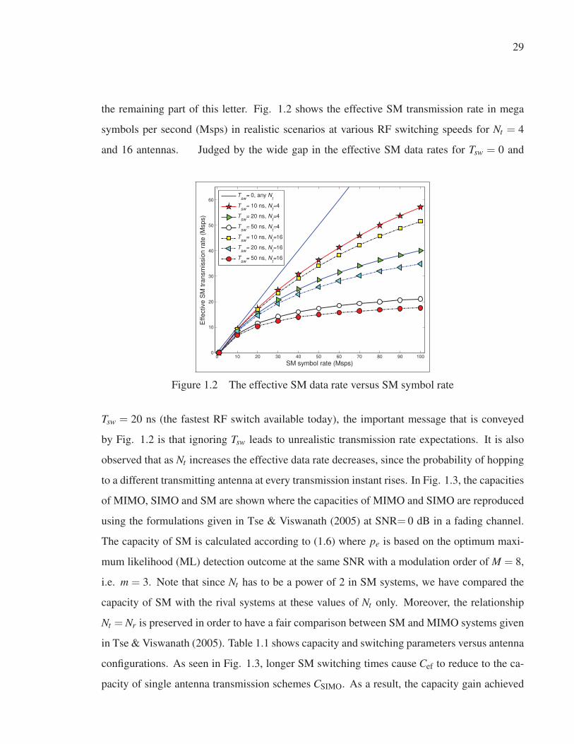
the remaining part of this letter. Fig. 1.2 shows the effective SM transmission rate in mega
symbols per second (Msps) in realistic scenarios at various RF switching speeds for Nt = 4
and 16 antennas. Judged by the wide gap in the effective SM data rates for Tsw = 0 and
0 10 20 30 40 50 60 70 80 90 1000
10
20
30
40
50
60
SM symbol rate (Msps)
Effe
ctiv
e S
M tr
ansm
issi
on r
ate
(Msp
s)
Tsw
= 0, any Nt
Tsw
= 10 ns, Nt=4
Tsw
= 20 ns, Nt=4
Tsw
= 50 ns, Nt=4
Tsw
= 10 ns, Nt=16
Tsw
= 20 ns, Nt=16
Tsw
= 50 ns, Nt=16
Figure 1.2 The effective SM data rate versus SM symbol rate
Tsw = 20 ns (the fastest RF switch available today), the important message that is conveyed
by Fig. 1.2 is that ignoring Tsw leads to unrealistic transmission rate expectations. It is also
observed that as Nt increases the effective data rate decreases, since the probability of hopping
to a different transmitting antenna at every transmission instant rises. In Fig. 1.3, the capacities
of MIMO, SIMO and SM are shown where the capacities of MIMO and SIMO are reproduced
using the formulations given in Tse & Viswanath (2005) at SNR= 0 dB in a fading channel.
The capacity of SM is calculated according to (1.6) where pe is based on the optimum maxi-
mum likelihood (ML) detection outcome at the same SNR with a modulation order of M = 8,
i.e. m = 3. Note that since Nt has to be a power of 2 in SM systems, we have compared the
capacity of SM with the rival systems at these values of Nt only. Moreover, the relationship
Nt = Nr is preserved in order to have a fair comparison between SM and MIMO systems given
in Tse & Viswanath (2005). Table 1.1 shows capacity and switching parameters versus antenna
configurations. As seen in Fig. 1.3, longer SM switching times cause Cef to reduce to the ca-
pacity of single antenna transmission schemes CSIMO. As a result, the capacity gain achieved

30
Table 1.1 Capacity and switching parameters vs. antenna setup
Nr = Nt 2 4 8 16nt 1 2 3 4
pe 0.136 0.080 0.031 0.006
SM & MIMO (Nt ×Nr) 2×2 4×4 8×8 16×16
SIMO (1×Nr) 1×2 1×4 1×8 1×16
βth based on (1.12) 0.3634 0.4693 0.6281 0.6783
by spatial modulation is lost and, effectively, using SM to enhance capacity becomes useless
and obsolete when β exceeds the threshold βth. Fig. 1.3 clearly shows that SM achieves a
higher capacity in comparison to SIMO as long as β does not exceed βth, which confirms our
analytical results with respect to the threshold value βth. In summary, growing β values push
the Cef curves down towards CSIMO, which is in line with our analysis. Finally, the spectral
2 4 6 8 10 12 14 16
1
2
3
4
5
6
7
8
Number of antennae
Cap
acity
bits
/ s
/ Hz
MIMOSIMOMISOSM ( β = 0)SM ( β = 0.20)SM ( β = 0.50)SM ( β = 0.67)
Figure 1.3 Capacities of MIMO, SM and SIMO systems
efficiency η vs. β calculated according to (1.15) is shown in Fig. 1.4 for various values of
Nt and for a roll-off factor α = 0.22 which is recently adopted in long-term evolution (LTE)
filters Dahlman et al. (2013). The asymptotic lower bound in Fig. 1.4 concerns the insertion of
an empty slot of duration Tsw at every transmission to relax receiver synchronization, whether
antennas switch or not, which also corresponds to very large Nt , as remarked in (1.4).

31
0 0.1 0.2 0.3 0.4 0.5 0.6 0.7 0.8 0.9 10.4
0.45
0.5
0.55
0.6
0.65
0.7
0.75
0.8
0.85
β = Tsw
/ Ts
Spe
ctra
l Effi
cien
cy η
Nt = 2
Nt = 4
Nt = 8
Nt = 16
Figure 1.4 SM Spectral efficiency η versus β for various values of Nt
1.5 Conclusions
In this work, we consider the effect of switching time which is an inherent property of RF
industrial switches on SM systems. Switching time being in the order of nanoseconds naturally
influences the transmission rate of SM systems because of introducing systematic transmission
pauses. Given the speed limitation of practical RF switches in performing transitions, antenna
transition-based technologies like SM schemes are capped in terms of data rate performance.
In fact, the effective data rate of SM will remain hostage to developments in industrial RF
switches. This brings restrictions to the implementation and operation issues when extremely
high data rates become a necessity. Since the technology marches towards emerging systems
where bandwidth efficiency and data rate are both essential requirements, it is necessary to
develop new SM techniques based on minimum transition of antennas, or on the transition of a
group of antennas at a time rather than schemes that require a transition at every transmission
instant. It is shown by the assemblage of our results that the switching time Tsw which is
a requirement for transitions between antennas to happen, dictates restrictions on data rate,
capacity and spectral efficiency of SM systems.


CHAPTER 2
FREQUENCY INDEX MODULATION FOR LOW COMPLEXITY LOW ENERGYCOMMUNICATION NETWORKS
Ebrahim Soujeri1, Georges Kaddoum1, Minh Au1 and Marijan Herceg2
1 Department of Electrical Engineering, École de Technologie Supérieure,
1100 Notre-Dame West, Montreal, Quebec, Canada H3C 1K32 Department of Communications, Faculty of Electrical Engineering, Computer Science and
Information Technology Osijek, Croatia
Paper published in IEEE Access, June 2017.
Abstract
In this paper, we propose a low complexity multi-user communication system based on fre-
quency index modulation that suits Internet of Things (IoT) applications. This system aims
to reduce the transmitted energy and the peak-to-average-power ratio (PAPR) of orthogonal
frequency-division multiplexing (OFDM) systems and to perform without sacrificing data rate
in comparison to conventional OFDM. In this design, OFDM-like signals are used to make the
implementation of the system easy by virtue of fast Fourier transform (FFT). In the proposed
scheme, the OFDM bandwidth of NFIM total sub carriers is divided into NB equal number of
sub-bands, with N subcarriers in every sub-band. At the transmitter side of each sensor, the bit
stream is divided into two blocks: mapped and modulated. The bits within the mapped block
are used to activate the corresponding subcarrier in its predefined sub-band in order to carry the
data of the modulated block, while the other N −1 subcarriers are nulled out. At the receiver,
the FFT is performed first, then the square-law envelope detector is applied to estimate the
active frequency index to recover the mapped bits, followed by a conventional demodulation to
demodulate the transmitted bits. Once the system is presented and analysed, energy efficiency,
PAPR and complexity are studied to show the features of the proposed scheme. Moreover, we
derive closed-form expressions of the bit error rate (BER) performance over Rayleigh fading
channels and we validate the outcome by simulation results. With the characteristics exhibited
in this work, the proposed system would constitute an excellent candidate for wireless sen-

34
sor applications, where it represents a simpler substitution for frequency-hopping (FH) based
architectures, in which the hops carry extra bits.
2.1 Introduction
Recently, there has been an escalating demand for higher data rate communication systems that
is associated with an increasing need in the number of devices, gadgets and wireless services.
On the one hand, the 5G infrastructure public private partnership has set the goal of reaching
1000 times more speed compared to what we had in 2010, while the power to-be-consumed to
run such networks are desired to be around 10% of the consumption at that time Pirinen (2014).
On the other hand, the concept of internet of things (IoT) has advanced in parallel to the de-
velopments in 5G networks by virtue of wireless sensor networks (WSN) that have emerged
as the most promising technologies for the future that touch various aspects of our life like
fitness, automation, security, localization, consumer electronics, smart grid devices and many
more Rawat et al. (2014). In fact, WSNs have been among one of the most researched areas in
the last decade. The emergence of this technology has only been possible via advances in and
availability of small, inexpensive and smart sensors that are cost effective and easily deploy-
able Rawat et al. (2014). Various modulation types have so far been used in wireless sensor
nodes, among these schemes are M−ary quadrature amplitude modulation (MQAM), offset
quadrature phase-shift keying (OQPSK) and multiple frequency-shift keying (MFSK), which
is also known as the green modulation scheme providing the advantage of low complexity and
low cost of implementation in comparison to other schemes Abouei et al. (2010).
It is to be mentioned that in order to increase data rate, alternative index modulation schemes
such as spatial modulation, code index modulation, subcarrier-index modulation, etc, have
been proposed to achieve both high data rate and energy efficiency in emerging networks. To
achieve this goal, indexing certain parameters of the communication system into the transmis-
sion mechanism in order to enable the conveyance of extra bits per symbol, at neither exagger-
ated bandwidth cost nor increased transmission power cost has been seriously considered in
the last decade.

35
In this context, spatial modulation (SM) which uses index modulation by multiple antennae
in order to increase the data rate and partially enhance the transmission capacity, has been
considered in Mesleh et al. (2006a, 2008); Jeganathan et al. (2008b); Di Renzo et al. (2014).
In this approach, antenna number or antenna index is used as an extra parameter to convey
information and enhance transmission data rate. At each transmission instant, only one transmit
antenna in the set is active while all other antennae are inactive. Nonetheless, this scheme
has not been cost free either, since it totally depends on the channel characteristics, requires
a continuous update of the CSI which imposes noticeable transmission overheads Di Renzo
et al. (2011) and is very fragile with respect to both noisy CSI estimation as well as correlated
channels Chang et al. (2013); Soujeri & Kaddoum (2015). Besides, switching time is a major
impediment that caps the ambitions related to the implementation of this system in real-life
scenarios. The recent study of Soujeri & Kaddoum (2016) has shown that switching time, i.e.
the duration of time needed by RF switches to carry out transitions between antennae, limits
the ambitions of SM and introduces noticeable gaps between projected and actual data rates.
Furthermore, code index modulation-spread spectrum (CIM-SS) has also been proposed as an
alternative index-based modulation to achieve higher throughput Kaddoum et al. (2015b). This
system uses spreading codes to map the data in conjunction with the constellation symbols.
In this configuration, bits are grouped into two categories, mapped bits and modulated bits.
Mapped bits choose a spreading code from a set of predetermined codes in order to spread
the modulated bit. At the receiver, the spreading code is first detected using the maximum
autocorrelation value and then the transmitted bit is demodulated.
Additionally, subcarrier index modulation (SIM) scheme has been proposed in Abu-Alhiga & Haas
(2009) where it is merged with orthogonal frequency division multiplexing (OFDM) to consti-
tute SIM-OFDM. Moreover, enhanced subcarrier index modulation (ESIM) has been proposed
to avoid the propagation of error by replacing the concept of majority counting by a simpler
method in which a pair of off-on or on-off subcarriers is used to represent a single bit Tsonev
et al. (2011), however, the fact that two subcarriers are used to transmit a single bit doubles the
required bandwidth necessary for transmission in this method.
36
Eventually, a transmission scheme called OFDM with index modulation (OFDM-IM) is pro-
posed Basar et al. (2013). In this scheme, information is conveyed not only by M-ary signal
constellations as in classical OFDM, but also by the indices of the subcarriers, which are acti-
vated according to the incoming information bits. But the implementation of this last scheme is
hard as it relies on maximum likelihood (ML) detection that requires a lot of computing charges
as it needs to search over all the possibilities (subcarrier combinations) within a bandwidth.
This is costly as it makes a joint search over all possibilities Basar (2015) and is impractical
for large combination values due to its exponentially growing decoding complexity Basar et al.
(2013), which makes it unsuitable for WSN applications. Furthermore, the Log-Likelihood
Ratio (LLR) detection strategy is another detection method proposed for this scheme for high
number of subcarriers, but this detector may produce an undefined set of active indices not at
all included in the original mapping table Basar et al. (2013).
In this work, we introduce a modified frequency index modulation (FIM) scheme that is simpler
than the approach of Basar et al. (2013). This system has a lower complexity compared to
OFDM-IM, low power consumption profile and does not sacrifice data rate as it makes use
of the frequency hops in a smart and wise way. As the proposed system does not use all of
the available subcarriers, it will also enjoy inter-carrier interference -free transmission while it
allows the transmission of additional bits in the index domain. Therefore, the proposed system
is an excellent choice for WSNs.
In the proposed FIM scheme, the OFDM bandwidth is divided into equal NB sub-bands of N
subcarriers each. A message is divided into mapped and modulated blocks where the mapped
block activates a single corresponding subcarrier in its predefined sub-band in order to carry the
data of the modulated block. At the receiver side, FFT is first performed on the received signal
followed by sub-sectioning the bandwidth into NB sub-bands where square-law envelope detec-
tor (SLED) is used in each sub-band to identify the active subcarrier. Then, the mapper chooses
the corresponding indexed message and demodulates the received signal over the channel to
get the remainder. While the proposed system keeps the architecture simple and constitutes an
excellent substitution for the conventional frequency-hopping (FH) technique in which hops

37
carry no additional information. Moreover, despite the simplicity, the proposed system enjoys
all the specifications associated with frequency hopping systems from the signal, interference,
channel and anti-jamming points of view. Furthermore, the system has a low PAPR profile and
may be used in multi-user or multi-node scenarios thanks to OFDMA multiple access tech-
nique. These properties make FIM scheme suitable for IoT applications where size, simplicity
and efficiency say the final word Barnaghi et al. (2012).
In summary, the low complex FIM system with its simple mapping method is briefly described.
The analytical bit error rate (BER) expressions over Rayleigh fading channel are derived and
are cross-checked with simulation results to show the accuracy extent of our analytical expres-
sions. Further, the energy efficiency and PAPR of the proposed system are analysed. Finally,
the BER performance of this scheme is compared with similar modulation techniques to show
the FIM system superiority compared to is counterparts.
The rest of the paper can be summarized as follows. In Section 2.2, the proposed system
model is presented. Performance analysis of the FIM is demonstrated in Section 2.3. En-
ergy efficiency and complexity are discussed in 2.4. In Section 2.5, we present numerical and
simulation results and Section 2.6 provides concluding remarks.
2.2 System Model
In this section, the FIM transmitter and the receiver architectures will be described in detail.
2.2.1 The Transmitter
A block diagram of the proposed FIM system is presented in Fig. 2.1. The FIM scheme divides
the OFDM bandwidth of NFIM total sub carriers into NB equal sub-bands of N subcarriers each.
Since each FIM sub-block has the same processing procedure, we consider the ith sub-band for
simplicity hereafter. In the FIM transmitter, the bit stream in every sub-band is divided into
blocks of pn = p1 + p2 bits, where p1 denotes the number of mapped bits while p2 represents
the number of modulated bits. As such, the outgoing bit stream can be written as bi = [bp1i ,bp2
i ],
38
where bi ∈ {0,1}(p1+p2), bp1i = [b1
i , · · · ,bp1i ] and bp2
i = [bp1+1i , · · · ,bp2
i ] are the two sub-blocks
that represent p1 mapped and p2 modulated bits, respectively. Subsequently, the vector bp1i ∈
{0,1}p1 , of p1 = log2(N) bits, chooses one active subcarrier index I ∈ {0, · · · ,N −1} out of N
available indices in the sub-band. The transformation of mapped bits into an active subcarrier
index is performed by the index selector module. Fig. 2.2 illustrates the case where bp1i = [0 1]
which leads to the activation of the second subcarrier, i.e. Ii = 2 out of 4 available subcarriers
in the sub-band.
On the other hand, the vector bp2i ∈ {0,1}p2 , of p2 = log2(M) bits, is mapped onto the con-
sidered M-ary signal constellation to produce the transmitted symbol si. The symbol si is
transmitted over the selected subcarrier indexed by Ii, while the other N − 1 subcarriers are
inactive and set to zero. The transmitted symbol si has an energy Es = E[sis∗i ] = p2Eb where
Eb is the bit energy.
2.2.2 Total Mapped Bits pT
Once the frequency modulation system with a total number of available frequencies NFIM =
NB×N that is split into NB number of sub-bands such that NFIM = NB×N is set up, the records
shown in Table 2.1 may be discussed. In fact, Table 2.1 describes the total number of transmit-
table mapped bits pT = NB× p1 = NB× log2(N) in the FIM system with respect to the number
of sub-bands NB for different NFIM. Observe that the FIM system has a capacity to transmit a
total of NB × pn bits in every transmission instant. Since both the peak power in the system as
well as the BER performance depend on the number of active frequencies in a sub-band, Table
2.1 will be revisited again later, when we discuss PAPR analysis and simulation results in the
sections that follow.
Also, since part of transmitted bits are conveyed by the frequency index, and to have a fair
comparison with other conventional systems, we define an equivalent system bit energy EbS
which represents the effective energy consumed per transmitted bit. This equivalent system bit

39
Table 2.1 FIM transmits a total of pT mapped bits using
NB number of sub-bands with N frequencies each
NFIM 4 8 16 32 64 128 256
NB 2 2 2 2 2 2 2
N 2 4 8 16 32 64 128
pT 2 4 6 8 10 12 14
NB 4 4 4 4 4 4
N 2 4 8 16 32 64
pT 4 8 12 16 20 24
NB 8 8 8 8 8
N 2 4 8 16 32
pT 8 16 24 32 40
NB 16 16 16 16
N 2 4 8 16
pT 16 32 48 64
NB 32 32 32
N 2 4 8
pT 32 64 96
NB 64 64
N 2 4
pT 64 128NB 128
N 2
pT 128
energy is related to the physically modulated bit energy by the relationship
EbS =p1 + p2
p2Eb =
pn
p2Eb. (2.1)
While the energy described in (2.1) allows the comparison of our system to other systems from
the performance point of view, it also is an indication of the energy efficiency achieved by the
proposed system. Furthermore, to construct the FIM sub-block of N elements in the frequency
domain, we consider the selected active subcarrier index Ii and the modulated M-PSK symbol
si, in order to form the vector
Xi = [Xi(0), · · · ,Xi(N −1)], (2.2)

40
NT –
pointIFFT
P/S D/A
1s1I
BNs
BNI
iI
is
0
0
0
000
00
0
1X )0(y
)1( TNy
)(ty
bits of block
bb
b21
211
1
110101
pp
pp
Mapper
M-aryModulator
iX
BNX
bits of block
bb
b21
21
10100pp
i
pi
pi
bits of block
bb
b21
21
11101pp
N
pBN
pBN
B
Mapper
M-aryModulator
Mapper
M-aryModulator
(a)
11
ˆ pb
)0(r
)1( −TNr
2,1
21,1
)(
)(
⋅=
⋅=
Nc
c
2,
21,
)(
)(
⋅=
⋅=
NN
N
B
B
c
c
argm
ax{c}
1I
BNI
iIFIMb
argm
ax{c}
)(tr
1ˆ pNB
b
1ˆ pib
2ˆ pNB
b
2ˆ pib
21
ˆ pb
1X
BNX
(b)
Figure 2.1 Block diagram of the general structure of FIM
communication system: a) the transmitter, and b) the receiver
where
Xi(k) =
⎧⎪⎨⎪⎩0, k �= I,
si, k = I, for k = 0, · · · ,N −1.
(2.3)

41
f1 f2 f3 f400 01 10 11
Figure 2.2 A given FIM system with 4 subcarriers. In the illustration, the transmitter has
indexed the message 01 and transmits the rest of the message via the subcarrier f2 only
For simplicity, the insertion and removal of cyclic guard prefix is not expressed in our mathe-
matical equations.
The frequency index modulators in each sub-band of the transmitter obtain the FIM subblocks
first and then concatenate these subblocks to form the main FIM blocks. So, the complete FIM
transmitted block that incorporates all sub-bands (from 1 until NB) would be stated as
y(t) =1√TN
NB
∑i=1
N−1
∑k=0
Xi(k)e j2π fi,kt , 0 ≤ t ≤ TN , (2.4)
where fi,k is the kth subcarrier frequency in the ith sub-band with a predefined bandwidth of
fi,k = N(i−1)/TN + k/TN with TN being the time duration of a FIM symbol.
2.2.3 The Receiver
In this paper, we consider transmissions over a Rayleigh fading channel corrupted by an ad-
ditive Gaussian noise channel. The received signal in the ith sub-block can be expressed as a
vector of N samples Xi =[Xi(0), · · · , Xi(N)
]such that
Xi(k) =
⎧⎪⎨⎪⎩Z′
i , k �= I,
Hisi +Zi, k = I, for k = 0, · · · ,N −1.
(2.5)
42
where Hi ∼ CN (0,1) is the FFT output produced by the Rayleigh fading channel effect, Z′i
and Zi are independent complex AWGN, with zero mean and variance N0. In order to reduce
the complexity of the receiver, a SLED is used to estimate the active subcarrier index in the
ith sub-block. Thus, the output variables in the vector Xi are fed to SLED forming N decision
variables such that for k = 0, · · · ,N −1, we have
ci,k = |Xi(k)|2 =
⎧⎪⎨⎪⎩|Z′
i |2, H0
|Hisi +Zi|2,H1
(2.6)
where H0 and H1 are two hypotheses with which H0 is verified if there is no signal, and
H1 is the alternative that indicates the presence of si. The SLED chooses the maximum value
in order to estimate the active subcarrier index, such that the estimate of the active subcarrier
index would be expressed as
Ii = argmaxk
{ci,k},k ∈ {0, · · · ,N −1} . (2.7)
Therefore, the decision variable might land in H1 if Ii = Ii. By estimating the active subcarrier
index Ii, the receiver can extract p1 mapped bits. The receiver then demodulates the corre-
sponding branch output using a conventional M-PSK demodulator to extract the remaining p2
modulated bits.
2.3 FIM Performance Analysis
In this section, we determine the performance of the proposed FIM system, in order to examine
the advantages of mapping information bits into subcarrier indices.
2.3.1 BER Analysis of FIM
In the FIM scheme, the transmitted data in every sub-band is divided into two blocks; the
mapped bits block and the modulated bits block. The mapped bits block determines which
subcarrier will be active and, hence, will be modulated by the modulating bits, contained in

43
the modulated bits block. Therefore, the FIM system BER probability consists of the BER
probability of mapped bits Pmap and the BER probability of modulated bits Pmod. Subsequently,
the FIM BER could be described as
PFIM =p1
p1 + p2Pmap +
p2
p1 + p2Pmod. (2.8)
In (2.8) above, the probability of error is prorated to the number of bits in every category and
the errors committed in that category. In order to derive the BER probability of mapped bits
Pmap, the erroneous probability of active subcarrier index detection Ped should be derived. Er-
roneous active subcarrier index detection causes a wrong mapped bits combination estimation.
Each wrong combination can have a different number of incorrect bits compared to the cor-
rect combination. Therefore, the probability of erroneous active subcarrier index detection is
converted into the corresponding BER probability of mapped bits by using
Pmap =2(p1−1)
2p1 −1Ped. (2.9)
In order to calculate the BER of the modulated bits Pmod, we consider that this probability
depends on the correct estimation of the active subcarrier index and the BER probability of
M-ary PSK modulation. Therefore, an error may occur in two different ways. The first case
is when the active subcarrier index is correctly estimated but an error occurs in the M−PSK
demodulation process. The second case is when an error occurs in the estimation of the active
subcarrier index, and the modulated bits are estimated using the wrong subcarrier. In this case,
the M−PSK modulated symbol will have to be guessed. In fact, the probability of correct
detection will be simply equal to 1M . Consequently, the BER probability of the modulated bits
would be expressed as
Pmod =1
p2
[PS,MPSK(1−Ped)+
M−1
MPed
], (2.10)
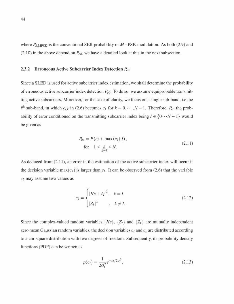
44
where PS,MPSK is the conventional SER probability of M−PSK modulation. As both (2.9) and
(2.10) in the above depend on Ped, we have a detailed look at this in the next subsection.
2.3.2 Erroneous Active Subcarrier Index Detection Ped
Since a SLED is used for active subcarrier index estimation, we shall determine the probability
of erroneous active subcarrier index detection Ped. To do so, we assume equiprobable transmit-
ting active subcarriers. Moreover, for the sake of clarity, we focus on a single sub-band, i.e the
ith sub-band, in which ci,k in (2.6) becomes ck for k = 0, · · · ,N − 1. Therefore, Ped the prob-
ability of error conditioned on the transmitting subcarrier index being I ∈ {0 · · ·N −1} would
be given as
Ped = P(cI < max(ck)|I) ,for 1 ≤ k
k �=I≤ N.
(2.11)
As deduced from (2.11), an error in the estimation of the active subcarrier index will occur if
the decision variable max(ck) is larger than cI . It can be observed from (2.6) that the variable
ck may assume two values as
ck =
⎧⎪⎨⎪⎩|Hs+ZI|2 , k = I,
|Zk|2 , k �= I.(2.12)
Since the complex-valued random variables {Hs}, {ZI} and {Zk} are mutually independent
zero mean Gaussian random variables, the decision variables cI and ck are distributed according
to a chi-square distribution with two degrees of freedom. Subsequently, its probability density
functions (PDF) can be written as
p(cI) =1
2σ2I
e−cI/2σ2I , (2.13)

45
where the variance σ2I is given by
σ2I = E
(|Hs+ZI|2
)= E
((Hs+ZI)(Hs+ZI)
∗)= E(|H2|)Es +N0 = N0(1+ γs),
(2.14)
where γs = E(|H|2)Es/N0 is the average signal-to-noise ratio (SNR). Since the usual metrics
for BER performance analysis in digital communications is the Eb/N0, the expression (2.14)
can be rewritten as
σ2I = N0(1+ p2γb), (2.15)
where γb = E(|H|2)Eb/N0. Similarly, for k �= I, the variance σ2k is calculated based on the PDF
p(ck) =1
2σ2k
e−ck/2σ2k (2.16)
that results in
σ2k = E
(|Zk|2)= N0, for 1 ≤ k
k �=I≤ N. (2.17)
The probability of erroneous active subcarrier index estimation is equal to 1 minus the probabil-
ity that cI > ck, for 1≤ kk �=I
≤N. Since the signals are orthogonal and the AWGN are statistically
independent, the random variables in (2.12) are mutually statistically independent. Hence, for
a given I the joint probability P({cI > ck}|I), for 1 ≤ kk �=I
≤ N is equal to P(cI > ck|I), for k �= I,
raised to the N − 1 st power. Furthermore, we may now evaluate the probability P(cI > ck|I)by applying
P(cI > ck|I) =∫ cI
0p(ck)dck. (2.18)

46
The evaluation of the above integral results in Proakis (2001)
P(cI > ck|I) = 1− e− cI
2σ2k . (2.19)
Raising the result of (2.19) to the power N −1 and averaging over all possible values of cI will
yield the probability of correct decision Pcd.
Pcd =∫ ∞
0p(cI)
[1− e
− cI2σ2
k
]N−1
dcI. (2.20)
Since p(cI) as been defined in (2.13), we get
Pcd =∫ ∞
0
1
2σ2I
e− cI
2σ2I
[1− e
− cI2σ2
k
]N−1
dcI
=∫ ∞
0
1
1+ p2γbe−
cI1+p2 γb
[1− e−cI
]N−1 dcI, (2.21)
Note that the term [1− e−cI ]N−1
which appears in (2.21) may be expressed in a reduced form
as
[1− e−cI
]N−1=
N−1
∑k=0
(−1)k(
N −1
k
)e−kcI . (2.22)
Now, substituting (2.22) into (2.21), we get Proakis (2001)
Pcd =1
1+ p2γb
N−1
∑k=0
(−1)k(
N −1
k
)×
∫ ∞
0e−
cI1+p2 γb e−kcI dcI.
(2.23)
Unifying the exponential terms in the integral produces
Pcd =1
1+ p2γb
N−1
∑k=0
(−1)k(
N −1
k
)×
∫ ∞
0e−
(1+k+kp2 γb)cI1+p2 γb dcI.
(2.24)
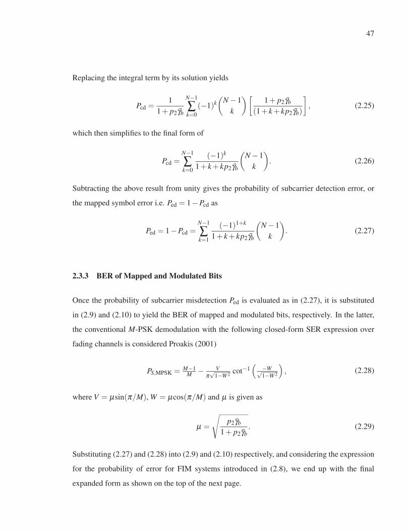
47
Replacing the integral term by its solution yields
Pcd =1
1+ p2γb
N−1
∑k=0
(−1)k(
N −1
k
)[1+ p2γb
(1+ k+ kp2γb)
], (2.25)
which then simplifies to the final form of
Pcd =N−1
∑k=0
(−1)k
1+ k+ kp2γb
(N −1
k
). (2.26)
Subtracting the above result from unity gives the probability of subcarrier detection error, or
the mapped symbol error i.e. Ped = 1−Pcd as
Ped = 1−Pcd =N−1
∑k=1
(−1)1+k
1+ k+ kp2γb
(N −1
k
). (2.27)
2.3.3 BER of Mapped and Modulated Bits
Once the probability of subcarrier misdetection Ped is evaluated as in (2.27), it is substituted
in (2.9) and (2.10) to yield the BER of mapped and modulated bits, respectively. In the latter,
the conventional M-PSK demodulation with the following closed-form SER expression over
fading channels is considered Proakis (2001)
PS,MPSK = M−1M − V
π√
1−W 2cot−1
(−W√1−W 2
), (2.28)
where V = μsin(π/M), W = μcos(π/M) and μ is given as
μ =
√p2γb
1+ p2γb. (2.29)
Substituting (2.27) and (2.28) into (2.9) and (2.10) respectively, and considering the expression
for the probability of error for FIM systems introduced in (2.8), we end up with the final
expanded form as shown on the top of the next page.

48
PFIM =1
pn
[(M−1
M−
√p2γb
1+p2γbsin(π/M)
π√
1− (√
p2γb1+p2γb
cos(π/M))2
cot−1( −
√p2γb
1+p2γbcos(π/M)√
1− (√
p2γb1+p2γb
cos(π/M))2
))
×N−1
∑k=0
(−1)k
1+ k+ kp2γb
(N −1
k
)+
M−1
M
N−1
∑k=1
(−1)1+k
1+ k+ kp2γb
(N −1
k
)]
+p1
pn
2(p1−1)
2p1 −1
N−1
∑k=1
(−1)1+k
1+ k+ kp2γb
(N −1
k
).
(2.30)
2.4 Energy Efficiency, PAPR and Complexity
In this section, we consider the energy efficiency, PAPR and complexity analyses for the pro-
posed FIM system.
2.4.1 Energy Efficiency
Table 2.1 demonstrates various possible configurations for a given total number of subcarriers
NFIM. We observe that when NFIM increases, we have more design options. In fact, we have
log2(NFIM/2) possible configurations, where for each configuration, different number of bits
are mapped. In the table, values of NFIM from 4 to 256 are shown. As clearly observed in Table
2.1, the maximum number of mapped bits in a FIM system with a total of NFIM frequencies is
equal to pT = NFIM/2. This maximum mapping is achieved in two ways, choosing N either 2
or 4. That is to say, to divide NFIM into sub-bands such that we have either 2 or 4 frequencies
in each sub-band. Choosing N = 2 halves the transmitted power, but it does not render a BER
performance improvement over the basic system. However, choosing N = 4 not only provides
a lower PAPR and a better power efficiency compared to N = 2, as only 1 out of 4 frequencies
becomes active, but achieves a BER enhancement and allows the system to carry an extra
mapped bit compared to the N = 2 case.

49
In the proposed FIM only NB p2 bits from the total NB(p1+ p2) are directly modulated using the
M-ary modulation, whereas NB p1 bits are conveyed in the selection of subcarriers. Considering
that each modulated bit requires an energy of Eb to be transmitted, then the mapping part
to index subcarriers should reduce the total required transmission energy. Consequently, the
percentage of the energy saving per subband in the proposed FIM is given by
Esaving =
(1− p2
p1 + p2
)Eb%
=
(1− 1
p1/p2 +1
)Eb%
(2.31)
Since we have defined p1 = log2(N) and p2 = log2(M), the energy saving depends on the ratio
of the number of subcarriers involved in indexing to the modulation order of the system. It
should be noted that for a fixed modulation order, an augmentation in the number of subcarriers
to be indexed yields more energy saving in the FIM system. Table 2.2 at the end of Section 2.5
provides a numerical example in relation to the energy saving discussed here.
2.4.2 PAPR Analysis
Taking into consideration the splitting of a full band that encompasses NFIM frequencies into
NB sub-bands with N frequencies each, we will have a glance at the PAPR behaviour of the
proposed system. The PAPR is a criterion to measure the success of a frequency modulation
system and is defined in OFDM systems for a transmit signal y(t) as Elavarasan & Nagarajan
(2015)
PAPRdB = 10 log10
max |y(t)|2E{|y(t)|2} (2.32)
to represent an indication of the non-linearity in the transmitter amplifier. PAPR is ideally
required to stay within the linear operational range of the RF amplifier at the transmitter. As-
suming that the real and imaginary parts of y(t) follow a Gaussian distribution, each with zero
mean and variance 12 in agreement with the central limit theorem, when NFIM is sufficiently
large, |y(t)| becomes a Rayleigh distribution and the power distribution has central chi-square

50
distribution with two degrees of freedom Han & Lee (2005). The cumulative distribution func-
tion (CDF) of the amplitude of a signal sample is given by
F(PAPR0) = 1− e−PAPR0 . (2.33)
If we assume that the average power of y(t) is equal to one, then the sampling values of different
sub-channels are mutually independent and identically distributed Rayleigh random variables
normalized with its own average power. Hence, the probability distribution function for PAPR
being less than a certain threshold value becomes
Pr(PAPR ≤ PAPR0) = F(PAPR0)NB
= (1− e−PAPR0)NB .(2.34)
However, when the performance for PAPR reduction techniques need to be evaluated, the com-
plementary cumulative distribution function (CCDF) of the PAPR is more frequently used Lit-
syn (2007), i.e. the probability that PAPR exceeds a predefined threshold value PAPR0, such
that
Pr(PAPR > PAPR0) = 1−Pr(PAPR ≤ PAPR0)
= 1−F(PAPR0)NB
= 1− (1− e−PAPR0)NB .
(2.35)
The partial selection of the subcarriers in FIM results in a reduction of the PAPR. Such a PAPR
reduction considerably decreases the consumed power and is not associated with any form of
penalty on the bit error rate (BER) performance.
2.4.3 System Complexity
The complexity of the FIM system can be evaluated by the number of operations required.
Since the FIM uses IFFT and FFT operations with a length of NFIM, the computational com-

51
plexity will be OFFT/IFFT ∼ O(2NFIM log2(NFIM)). Next, SLED multiplies the vector Xi by its
complex conjugate. Therefore, the computational complexity is simply OSLED ∼O(NNB). Re-
garding the modulation and the demodulation, we assume that a modulator converts a stream
of p2 bits into an M-ary symbol by computing an inner product between the bit stream and the
vector[2p2−1, · · · ,1]
. The demodulator will convert the symbol into a bit stream by comput-
ing p2 Euclidean divisions. As a result, the computational complexity of a modulator and a
demodulator will be OMod/Demod ∼ O(3p2 − 1) per active subcarrier. In total, the complexity
of the FIM system would be expressed as
OFIM = OFFT/IFFT +OSLED +NBOMod/Demod. (2.36)
In the conventional OFDM scheme, since all subcarriers are activated during the transmission,
the complexity will be
OOFDM = OFFT/IFFT +NNBOMod/Demod. (2.37)
Aiming at comparing the FIM system to a system that shares the same modulation concept but
with a different receiver design, we compare the complexity of FIM to that of OFDM-IM. In
the latter, only k out of N subcarriers are activated. However, the complexity of the maximum
likelihood detector is OMLD ∼ O(2p2Mk) per subcarrier where k = p2/ log2(M), Basar et al.
(2013).
OOFDM-IM = OFFT/IFFT + kNBOMod/Demod +OMLD. (2.38)
2.5 Simulation Results
In this section, we study the obtained analytical and simulation results for the proposed FIM
system and show that analytical and simulation results are in good agreement. Then we com-
pare the performance of FIM to other index-based schemes like SM and OFDM-IM system.
Finally, we study the energy efficiency, PAPR and complexity analyses for the proposed sys-
tem.

52
2.5.1 Performance of FIM
We shed light in this section on some of these parameters that influence the system the most,
we investigate the performance of the proposed frequency-index modulation system in various
scenarios and we compare the performance of our system to other modulation-index schemes
to show the performance superiority.
As the system may ferry a certain number of symbols per sub-band in every transmission using
various configurations, we start by plotting the overall BER performance of the FIM system
described by (2.8) for the transmission of 7 bits per sub-band using different combinations of
the modulation order M and the number of frequencies per sub-band N. The performance of
such a case is shown in Fig. 2.3. The first observation is that all configurations of the FIM sys-
tem show a superior BER performance to the conventional 128-ary PSK modulation in fading
channels. As a matter of fact, the 128-ary PSK has been chosen to compare, as it represents
the most basic well-known communication system that carries 7 bits. We also observe a great
match and conformity between analytical and simulation results for the FIM system, which
confirms the certitude of our approach. Furthermore, it also shows that under transmission rate
restrictions, our system is design-flexible and is adaptable to acquire several forms in terms
of M and N. This facilitates its practical application for WSNs. As both the modulation
order M and the number of frequencies per sub-band N constitute the fundamental parts of the
FIM design, we independently observe the BER performance of FIM with respect to each of
these parameters individually in the next two plots. Fig. 2.4 shows the BER performance of
the proposed FIM system versus the modulation order M, for N = 4 frequencies per sub-band.
As seen in Fig. 2.4, increasing M tightens up the Euclidean distance between the transmitted
symbols and degrades the BER performance, which is very well in line with communication
theory. Fig. 2.5 exhibits the BER performance of the proposed FIM system with respect to the
number of subcarriers per sub-band for a modulation order of M = 8. As witnessed in Fig. 2.5,
the BER performance of the proposed system shows a marginal improvement with increased
N. This is due to the fact that increasing N contributes to the total equivalent system bit energy
described earlier in (2.1). As a matter of fact, the BER performance would deteriorate without
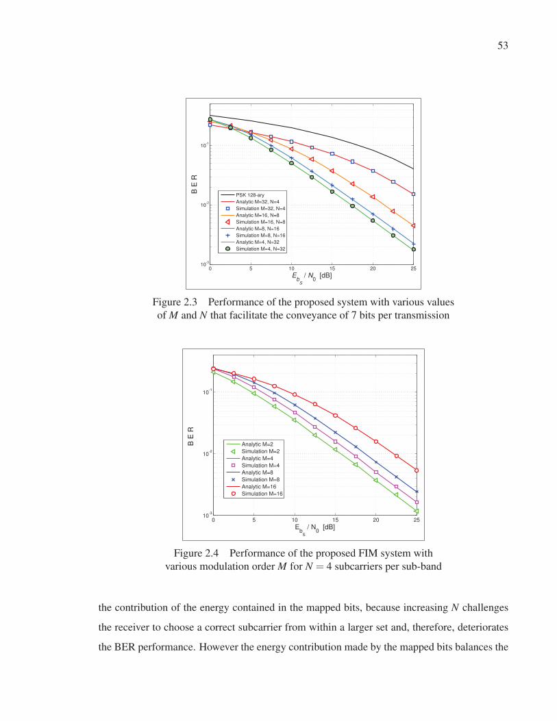
53
0 5 10 15 20 2510
-3
10-2
10-1
Eb
S
/ N0 [dB]
B E
R
PSK 128-aryAnalytic M=32, N=4Simulation M=32, N=4Analytic M=16, N=8Simulation M=16, N=8Analytic M=8, N=16Simulation M=8, N=16Analytic M=4, N=32Simulation M=4, N=32
Figure 2.3 Performance of the proposed system with various values
of M and N that facilitate the conveyance of 7 bits per transmission
0 5 10 15 20 2510
-3
10-2
10-1
Eb
S
/ N0 [dB]
B E
R
Analytic M=2Simulation M=2Analytic M=4Simulation M=4Analytic M=8Simulation M=8Analytic M=16Simulation M=16
Figure 2.4 Performance of the proposed FIM system with
various modulation order M for N = 4 subcarriers per sub-band
the contribution of the energy contained in the mapped bits, because increasing N challenges
the receiver to choose a correct subcarrier from within a larger set and, therefore, deteriorates
the BER performance. However the energy contribution made by the mapped bits balances the

54
performance. This figure affirms that the only price paid for conveying more mapped bits as N
gets larger is bandwidth expansion, not BER performance alteration.
0 5 10 15 20 2510
-3
10-2
10-1
Eb
S
/ N0 [dB]
B E
R
Analytic N=2Simulation N=2Analytic N=4Simulation N=4Analytic N=8Simulation N=8Analytic N=16Simulation N=16Analytic N=32Simulation N=32
Figure 2.5 Performance of the proposed FIM system for various
subcarriers per sub-band and a modulation order of M = 8
2.5.2 Performance Comparison with SM and OFDM-IM Systems
To exhibit the supremacy of the frequency index-modulation system despite its simplicity,
we compare the performance of our proposed work to the performance of two other index-
modulation based schemes, namely the spatial modulation (SM) and the orthogonal frequency
division multiplexing with index modulation (OFDM-IM) techniques. These two works are
very well explained in Mesleh et al. (2006a, 2008); Jeganathan et al. (2008b); Di Renzo et al.
(2014) and Basar et al. (2013). For simplicity, we consider a comparison with SM and OFDM-
IM for the case of dispatching 3 bits per transmission. In this case, the modulation order of SM
is set to M = 4, while the number of transmitting antennae is fixed at Nt = 2 transmitting anten-
nae versus a single receiving antenna, i.e. Nr = 1. We have chosen this case for SM as it shows
a better performance compared to the other way round, e.g Nt = 4 and M = 2. Furthermore, the
OFDM-IM system has 4 subcarriers in each sub-band, where 2 subcarriers are active. All the

55
three systems considered for comparison here are simulated under similar channel and fading
conditions. In order to have a fair comparison in terms of energy with with respect to SM, the
energy of SM has been reformulated in a fashion similar to (2.1) such that it incorporates the
energy of the mapped bits too, i.e. EbSM = log2(Nt)+log2(M)log2(M) ·EbSM0
where EbSM0is the default
energy of the SM system. As depicted in Fig. 2.6, the FIM system achieves a noticeable
0 5 10 15 20 2510
-3
10-2
10-1
Eb
S
/ N0 [dB]
B E
R
SM M=4, Nt=2, N
r=1
OFDM-IM (4,2)
FIM ana M=2, N=4
FIM sim M=2, N=4
Figure 2.6 Performance of FIM in comparison to SM and OFDM-IM
for the transmission of a total of 3 bits (mapped and modulated)
performance despite its simplicity and ease. The performance of the proposed FIM system is in
tight competition with OFDM-IM. It is of course possible to enhance the performance of any
of these index-modulation schemes by implementing more receiver antennae and increasing
reception diversity, however this is absolutely impractical for wireless sensor cases, where size
and simplicity are of extreme importance.
Indeed, the admirable advantage of the proposed system lies in its simplicity and suitability for
application in WSNs. Unlike SM that requires expensive and bulky hardware with a perfor-
mance totally antenna- and channel gain- dependent, and unlike OFDM-IM that is too complex
for WSNs implementation. Furthermore, both SM and OFDM-IM are ML-detector dependent,
the implementation of which becomes impractical for large combinations of M and N. In ad-
56
dition, neither SM nor OFDM-IM may function without the availability of perfect channel
state information at the receiver. In the proposed FIM scheme, however, the performance is
achieved without undergoing any expensive hardware expansion or complex algorithmic im-
plementation. Added that the proposed scheme may very well convey p1 bits per transmission
and detect them using the SLED, without having any knowledge of the channel state informa-
tion at all. This is absolutely not possible, neither with SM nor with OFDM-IM.
2.5.3 Energy Efficiency, PAPR and Complexity Analysis
In this subsection, we show the results concerning energy efficiency, PAPR and complexity
analyses in 3 different consecutive and independent clauses for sake of clarity.
2.5.3.1 Energy Efficiency and PAPR Analysis
We compare the CCDF of the PAPR in terms of number of sub-bands NB. This is because a
single subcarrier is activated in every sub-band, and in effect, only NB subcarriers are active
per every FIM transmission. Fig. 2.7 shows the theoretical CCDFs of the proposed FIM
system with different sub-bands for NFIM = 64 based on evaluating (2.35). Notice that the case
NB = 64, N = 1 in Fig. 2.7 corresponds to the PAPR of a conventional OFDM system with
64 subcarriers, where no frequency-indexing takes place. As clearly illustrated in Fig. 2.7,
increasing the number of subcarriers per sub-band N leads to lesser NB which in turn causes
the CCDF to diminish. It is observed here that the FIM system transmits fewer pT bits and
relaxes the PAPR for higher N and less NB. Conversely, more pT bits are transmitted for higher
NB and less N at the cost of higher PAPR values.
High PAPR can be avoided by reducing the number of subcarriers actually engaged in trans-
mission, and in effect, the PAPR is reduced in a fashion similar to clustered OFDM Cimini Jr
et al. (1996); Cimini Jr & Sollenberger (1997). Note that in the clustered OFDM technique
mentioned in Cimini Jr et al. (1996); Cimini Jr & Sollenberger (1997) the subcarriers are clus-
tered into several smaller blocks and transmitted over separate antennae. The PAPR is reduced

57
1 2 3 4 5 6 7 8 9 10
10-4
10-3
10-2
10-1
100
PAPR0 [dB]
Pr
( P
AP
R >
PA
PR
0 )
NB = 2, N = 32, p
T = 10
NB = 4, N = 16, p
T = 16
NB = 8, N = 8, p
T = 24
NB = 16, N = 4, p
T = 32
NB = 32, N = 2, p
T = 32
NB = 64, N = 1, p
T = 0 (OFDM)
Figure 2.7 CCDFs of the PAPR of the proposed FIM system
with complementing NB and N combinations for NFIM = 64
since there are fewer subcarriers per transmission. But that technique has not been widely em-
ployed since the increase in the number of power amplifiers makes their proposal impractical
in many applications. However, in our work, we have a single antenna and the implementation
of several antennae has been substituted by using a frequency-indexing method. Brief, we re-
duce PAPR by clustering using various frequency bands instead, to replace the deployment of
several antennae.
Regarding the energy efficiency, the proposed FIM system the energy saving is significant
as the number of mapped bits increases (see (2.31)). Compared to FH or OFDM systems,
the FIM system is competitive in terms of energy efficiency for a given number of bits per
transmission. Instead of using a pseudo-random generator to select a frequency as in FH, FIM
activates one subcarrier which is selected by the mapper (the index selector). As a result,
if pn = p1 + p2 bits need to be transmitted, FH systems will use EFH = pnEb whereas FIM
system will dispose EFIM = p2Eb, where Eb is the energy to transmit one bit. For example, for
pn = 2 bits per transmission, it is possible to use one bit for index mapping and another bit for
modulation in the FIM system whereas both bits will be transmitted via the activation of various
hoppings in the FH. Under this condition, from (2.31), FIM will save 50% of energy compared
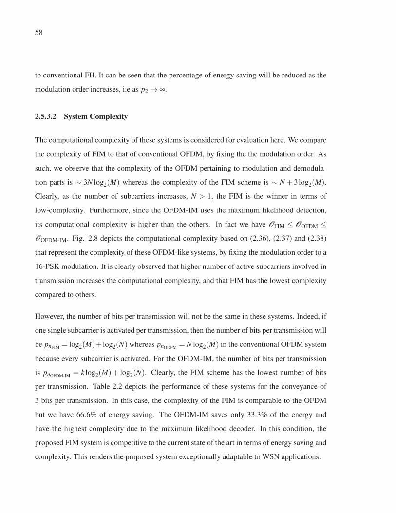
58
to conventional FH. It can be seen that the percentage of energy saving will be reduced as the
modulation order increases, i.e as p2 → ∞.
2.5.3.2 System Complexity
The computational complexity of these systems is considered for evaluation here. We compare
the complexity of FIM to that of conventional OFDM, by fixing the the modulation order. As
such, we observe that the complexity of the OFDM pertaining to modulation and demodula-
tion parts is ∼ 3N log2(M) whereas the complexity of the FIM scheme is ∼ N + 3log2(M).
Clearly, as the number of subcarriers increases, N > 1, the FIM is the winner in terms of
low-complexity. Furthermore, since the OFDM-IM uses the maximum likelihood detection,
its computational complexity is higher than the others. In fact we have OFIM ≤ OOFDM ≤OOFDM-IM. Fig. 2.8 depicts the computational complexity based on (2.36), (2.37) and (2.38)
that represent the complexity of these OFDM-like systems, by fixing the modulation order to a
16-PSK modulation. It is clearly observed that higher number of active subcarriers involved in
transmission increases the computational complexity, and that FIM has the lowest complexity
compared to others.
However, the number of bits per transmission will not be the same in these systems. Indeed, if
one single subcarrier is activated per transmission, then the number of bits per transmission will
be pnFIM = log2(M)+ log2(N) whereas pnODFM= N log2(M) in the conventional OFDM system
because every subcarrier is activated. For the OFDM-IM, the number of bits per transmission
is pnOFDM-IM= k log2(M)+ log2(N). Clearly, the FIM scheme has the lowest number of bits
per transmission. Table 2.2 depicts the performance of these systems for the conveyance of
3 bits per transmission. In this case, the complexity of the FIM is comparable to the OFDM
but we have 66.6% of energy saving. The OFDM-IM saves only 33.3% of the energy and
have the highest complexity due to the maximum likelihood decoder. In this condition, the
proposed FIM system is competitive to the current state of the art in terms of energy saving and
complexity. This renders the proposed system exceptionally adaptable to WSN applications.

59
1 16 32 48 64 80 96 112 12810
0
101
102
103
104
105
Number of subcarriers per sub-band: N
Num
ber
of O
pera
tions
FIMOFDMOFDM-IM (n = N,k = 2) ML
Figure 2.8 Complexity comparison of the proposed FIM, conventional OFDM and
OFDM-IM(n,k) systems using a number of subband NB = 1 and FFT-length NFIM = NNB
Table 2.2 Comparison, OFDM, OFDM-IM and FIM
systems for the conveyance of 3 bits per transmission
OFDM OFDM-IM(4,2) FIM M = 2, N = 4
Complexity 22 28 22
Energy saving 0% 33.3% 66.6%
2.6 Conclusions
In this paper, we have proposed a frequency-index modulation (FIM) scheme that suits the
physical layer of IoT applications. The proposed system uses OFDM waveforms for its ease
of implementation and flexibility. Unlike SM and OFDM-IM which are either hardware-
demanding or too complex to be implemented based on the index modulation technique, the
suggested system conveys addition information bits by virtue of the active frequency indices in
every sub-band. At the modulator side, the bit stream is divided into two blocks: mapped and
modulated. The bits within the mapped block are used to activate the corresponding subcarrier
to carry the data of the modulated block, while other subcarriers are nulled out. To recover
the transmitted and mapped data, an FFT is performed first, and then the square-law envelope
detector is applied to estimate the active frequency index to recover the mapped bits, followed

60
by a conventional demodulation to demodulate the transmitted bits. Furthermore, energy ef-
ficiency and complexity analyses have been carried out and it has been shown that PAPR is
decreased in such a structure, which demonstrates the appropriateness of our system for WSN
applications, where power and complexity must be kept at low profiles. Moreover, the closed-
form expressions of the BER performance over Rayleigh fading channels are derived. The
proposed modulation scheme meets the needs of 5G wireless systems to a great extent, reduces
PAPR, minimizes the consumed power, operates using a low latency and power profile and
shows a promising overall performance.

CHAPTER 3
DESIGN OF AN INITIAL-CONDITION INDEX CHAOS SHIFT KEYINGMODULATION
Ebrahim Soujeri1, Georges Kaddoum1 and Marijan Herceg2
1 Department of Electrical Engineering, École de Technologie Supérieure,
1100 Notre-Dame West, Montreal, Quebec, Canada H3C 1K32 Department of Communications, Faculty of Electrical Engineering, Computer Science and
Information Technology Osijek, Croatia
Paper published in Electronics Letters, February 2018.
Abstract
An initial condition index chaos shift keying modulation is proposed. This design aims to
increase the spectral and energy efficiencies to unprecedented levels. The proposed scheme
exploits the initial conditions to generate different chaotic sequences to convey extra bits per
transmission. In the proposed design, the input data stream is formed in blocks of ptot = n+1
bits. In this architecture, n bits are mapped into N = 2n predetermined initial conditions that
are used to generate unique chaotic sequences at the transmitter. At the receiver side, the prede-
termined initial conditions are used to generate a set of N chaotic sequences that are correlated
with the received signal. The index of the initial condition for which the chaotic sequence pro-
duces a maximum correlation with the received signal is selected to recover the mapped bits,
and the corresponding sequence is used to despread the transmitted modulated bit. To validate
the proposed scheme, the bit error rate over fading channels is analyzed and formulated and
the proposed system performance is compared with other conventional and index modulation
schemes. In comparison to rival modulation schemes, the results obtained in the proposed work
show a promising data rate boost and a competitive performance.

62
3.1 Introduction
During the last decade, a tremendous increase in the number of wireless devices has brought
new challenges for the wireless network industry. In particular, low energy consumption and
high spectral efficiency are among the most important and essential requirements for the in-
creasing number of wireless devices in wireless sensor networks (WSN), wireless body area
networks (WBAN) and internet of things (IoT) systems. Therefore, new technologies in wire-
less systems design have recently been investigated and developed to meet the needs of in-
creasing network demands. To be specific, WSNs and microsensors require the spread spec-
trum technology which is adopted by the IEEE 802.15.4 standard that comes under the broader
umbrella of the license-free industrial scientific and medical (ISM) bands. Concurrently, index
modulation has been proposed to increase data rate by carrying extra bits, at no or minimum
additional cost. In this vein, an alternative low energy consumption version of MIMO scheme
called spatial modulation (SM) in which the index of the active antenna along with constel-
lation symbols are used for bits mapping is proposed in Mesleh et al. (2008). By exploiting
the spreading code domain, the code index modulation (CIM) for spread spectrum systems is
recently proposed Kaddoum et al. (2016b). In the CIM scheme, the indices of spreading codes
are used in conjunction with symbol constellation for bits mapping. On the other hand, non-
coherent and coherent chaotic modulations have been proposed in the last two decades due
to their low complexity, low power consumption, robustness on multipath fading or increased
transmission security for coherent modulation schemes Kaddoum (2016b).
Recently, index modulation has been applied to non-coherent chaos-based modulation schemes
Xu et al. (2017); Cheng et al. (2017); Herceg et al. (2017). In Xu et al. (2017), a code-
shifted differential chaos shift keying (CS-DCSK) system exploiting Walsh codes indices to
map extra bits is proposed while in Cheng et al. (2017) the authors combine index modulation
with multicarrier DCSK. In addition, a system named permutation index DCSK (PI-DCSK)
modulation that supports multi-user access and secure transmission is proposed in Herceg et al.
(2017). Nonetheless, to the best of authors’ knowledge, index modulation with coherent chaos-
based modulation scheme has not been studied before.

63
In this letter, we apply for the first time the index modulation to a coherent secure chaos-based
scheme named chaos shift keying (CSK). This new scheme named initial condition index chaos
shift keying (ICI-CSK) aims to enhance the spectral and energy efficiencies. In this vein, the
proposed ICI-CSK scheme exploits the chaotic maps sensitivity on initial conditions to gener-
ate a large number of uncorrelated chaotic signals from the same chaotic map. In particular, at
the transmitter, data stream is formed in blocks of ptot = n+1 bits where the first n bits selects
an initial condition index from a set of N available initial conditions used to generate a chaotic
sequence of length β , while the remaining single bit is spread by the selected chaotic sequence.
At the receiver side, the received signal is correlated with a set of N chaotic signals that are gen-
erated using each of the initial conditions described at the transmitter. First, the output of each
correlator is squared to compute the received energy in order to allow the identification of the
correct initial condition used at the transmitter, by examining the maximum squared correlation
value. The index of chaotic sequence that produces the maximum correlation with the received
signal is selected to recover the n mapped bits and then sign of the correlator output is utilized
to recover the modulated bit. Note that increasing the number of mapped bits per transmission
to very large values would necessitate the use of more correlators at the receiver which could
lead to more reception complexity. Furthermore, the limit of allowed mapped bits is disclosed
in Kaddoum et al. (2016b) and has been respected in the proposed ICI-CSK scheme to keep
this system low complex. On the other hand, it was demonstrated in Kaddoum (2016b) that the
application of code synchronization techniques based on acquisition and tracking algorithms
to CSK schemes yield robust and reliable performance. Hence, these techniques can be used in
ICI-CSK to tackle the synchronization problem. In addition, large spreading factors are consid-
ered to avoid the bit energy variation in the ICI-CSK system Kaddoum (2016b). In the sequel,
analytical bite error rate (BER) expressions over flat Rayleigh fading channel is formulated
and validated via Monte Carlo simulations. Finally, the performance of ICI-CSK is analyzed
and compared to conventional schemes like spread spectrum M-PSK, and index-based schemes
like SM.

64
3.2 ICI-CSK system model
A block diagram of the proposed ICI-DCSK system is illustrated in Fig. 3.1. As shown, the
information bits of the outgoing data frame at the transmitter are arranged in blocks of ptot =
n+1 bits per transmission. For an ith block Bi = [si,bi] ∈ {1,−1}1×ptot , si represents n mapped
bits and bi is the transmitted bit with CSK modulation. In addition, a corresponding initial
condition vector of N predefined initial conditions given in the vector x0 = [x1,0, · · · ,xN,0]T ,
shared with the receiver, is used to generate the chaotic sequence to map the n bits of si. In this
vein, a selected initial condition x j,0 from the codebook, x0, corresponding to a given set of
mapped bits si is used to generate the chaotic sequence in order to spread the bit bi. As such,
the transmitted baseband signal ei takes the following form
[ ]TNxx
0,0,1 ,,
[ ]TNxx
0,0,1 ,,
i,1x
iN ,x
iD ,1
iND ,{ }
ijD
,ˆsgn ii b,s
Figure 3.1 A general scheme of the proposed ICI-CSK
architecture: (a) transmitter and (b) receiver
ei =√
Eb bi ·x j,i, (3.1)

65
where x j,i = [x j,1,i, · · · ,x j,β ,i] is the chaotic sequence of β chips generated using the jth ini-
tial condition, and Eb is the transmitted bit energy. Since the spreading length of the chaotic
sequence is β , the length of the ICI-CSK bit is Tb = βTc, where Tc is the duration of one
chip and is set to unity in this letter. Moreover, the second-order Chebyshev polynomial func-
tion x j,κ+1 = 1−2x2j,κ is used to generate chaotic sequences due to simplicity and reasonable
performance Kaddoum (2016b). The baseband received signal over quasi-static flat fading
Rayleigh channel is expressed as
ri = λi ei +ni, (3.2)
where λi is the quasi static fading channel coefficient over the ith ICI-CSK symbol duration,
and ni is a β -samples additive white Gaussian noise (AWGN) with zero mean and variance
N0/2. At the receiver, the received signal is correlated with N replicas of chaotic signals
generated with the same initial conditions from the set x0 used at the transmitter. Subsequently,
N correlator output variables are formed
Dm,i =< λi√
Eb bi x j,i +ni,λi xm,i > for m = 1, · · · ,N (3.3)
where < ·, · > stands for the inner product operator. To determine the corresponding initial
condition index, the square magnitudes of the N correlators are compared in order to find the
largest value
j = argmaxm
{|Dm,i|2
},m ∈ {1,2, · · · ,N} . (3.4)
By estimating the index j of the correlator with the largest energy output, the receiver knows
which initial condition is used for chaotic sequence generation at the transmitter side and hence,
the implicitly transmitted n number of mapped bits can be estimated. Furthermore, the mod-
ulated bit can be recovered by computing the sign of the correlator with maximum output as
bi = sgn(D j,i).

66
3.3 Probability of Error for Mapped Bits
In this part we will analyze the erroneous detection of the desired chaotic sequence. In fact,
provided that the jth initial condition x j,0 has been used for the generation of the chaotic se-
quence used in transmission, an error occurs in detecting the mapped bits if the largest square
absolute value of the mth correlator output is larger than the square absolute value of the jth
desired correlator output for any m �= j. Therefore, the probability that an erroneous correlator
output will be selected Ped would fit the description
Ped = P(∣∣D j,i
∣∣2< max
(|Dm,i|2
)| x j,0
),
for 1 ≤ mm�= j
≤ N.(3.5)
Since all correlator output variables are statistically mutually independent Kaddoum et al.
(2016b), the erroneous detection probability over fading channel is similar to M−ary orthog-
onal signalling Proakis (1995) and the work of Soujeri et al. (2017). Therefore, the final form
of (3.5) and considering γs = E(∣∣λ 2
∣∣)Eb/N0 where E(·) is the expectation operator, will be
expressed as
Ped =N−1
∑k=1
(−1)1+k
1+ k+ kγs
(N −1
k
). (3.6)
Since n bits are mapped into a given sequence, the mapped bit error rate probability is given
by Proakis (1995)
Pmap =2(n−1)
2n −1·Ped· (3.7)
3.4 BER Performance Analysis of the ICI-CSK System
In this section, we examine the performance of the ICI-CSK scheme. First, the probability
of error of transmitted modulated bit, b, for the ICI-CSK system depends on the detection
probability of the initial condition given in (3.6). That is to say, if the initial condition is

67
correctly identified, then the error will be that associated with bit error rate demodulation of
CSK scheme Pcsk, if not, the output is guessed with 50% chance of estimation error. Then, the
probability of error of the transmitted modulated bit, Pmod is expressed as
Pmod = (1−Ped) ·Pcsk +0.5 ·Ped (3.8)
where Pcsk is the bit erorr rate probability of the coherent chaotic shift keying system that does
not involve any indexing Kaddoum (2016b)
Pcsk =1
2
(1−
√γs
1+ γs
)· (3.9)
Once the probability of error of modulated bits Pmod and mapped bits Pmap are determined as
in equations (3.8) and (3.7) respectively, the overall bit error rate probability of the proposed
ICI-PSK system, PICI−CSK, can be formulated as
PICI−CSK =n
ptotPmap +
1
ptotPmod. (3.10)
Furthermore, since part of the transmitted bits are conveyed by the initial condition index, and
to have a fair comparison with other conventional systems, we define an equivalent system bit
energy Ebs which represents the effective energy consumed per transmitted bit and is related to
the physically modulated bit energy by the relationship Ebs = ptot ·Eb.
3.5 Simulation and Evaluation
The overall bit error probability of error of the proposed ICI-CSK system is evaluated accord-
ing to (3.10). Fig. 3.2 shows the BER performance of the proposed system for the transmission
of ptot = 4 and ptot = 6 bits for β = 128 over a flat fading channel, where a perfect match be-
tween analytical and simulation results is revealed. As witnessed in Fig. 3.2, a marginal BER
performance improvement is observed as N increases from 8 to 32 in the ICI-CSK system. This
returns to the fact that increasing n contributes to transmit more bits with a similar bit energy

68
Eb. Note that without the contribution of the energy contained in the mapped bits, the BER
performance would deteriorate as the receiver is challenged to pick up an initial condition from
a larger set. This evidence affirms that while the BER performance is minimally improved, the
only price paid for conveying more mapped bits is added complexity. Moreover, for fair com-
parison, the performance of our proposed scheme is compared to SM and conventional M-PSK
schemes transmitting the same number of bits ptot as ICI-CSK and over flat fading channel.
In this vein, SM scheme using BPSK modulation for Nt = 8 and Nt = 32 transmitted anten-
nas respectively, and PSK 16-ary and 64-ary are used. It is clearly shown that the proposed
system outperforms M-PSK and SM while maintaining a much simpler hardware architecture
compared to SM. This is because SM relies on channel state information to detect the active
antenna which leads to a higher probability of error compared to ICI-CSK. Finally, in the case
of M-PSK, the Euclidean distance between symbols is decreased as M increases while in the
ICI-CSK structure, augmenting ptot only increases the number of mapped bits as the Euclidean
distance is preserved at maximum and maintained constant since BPSK modulation is used in
the proposed ICI-CSK scheme.
0 5 10 15 20 2510
-3
10-2
10-1
100
Eb
S
/ N0 [dB]
B E
R
SM 4 bitsPSK 16-aryICI-CSK Ana 4 bitsICI-CSK Sim 4 bitsSM 6 bitsPSK 64-aryICI-CSK Ana 6 bitsICI-CSK Sim 6 bits
Figure 3.2 BER performance of ICI-CSK compared to SM and M-ary PSK
for the transmission of ptot = 4,6 bits. CSK sequence length β = 128

69
3.6 Conclusions
A new, simple, energy and spectral efficient coherent chaos-based communication system
named ICI-CSK is presented in this letter, where the initial condition of the chaotic sequence
is used as a new dimension to map information and carry extra bits. The proposed system
achieves high throughput and energy efficiency considering that a single information bit out of
ptot bits per transmission is physically transmitted. Judging by the results obtained, this system
will have a remarkable place in futuristic 5G sensor nodes and IoT applications where size,
simplicity and efficiency say the final word.


CONCLUSION AND RECOMMENDATIONS
Concluding Remarks
The futuristic 5G wireless communications is very ambitious in terms of high bandwidth and
large energy saving requirements. This fact has driven innovative research to be undertaken in
this direction. As index modulation is becoming one of the pioneer techniques to be used in
order to enhance the spectral and energy efficiencies of 5G communication systems, we have
considered this technique in this Ph.D study.
The work of Mesleh et al. (2008) is in fact the first in this contention that has received consider-
able attention from researchers in the field. However, SM modulation faces serious challenges
in terms of capacity achievement, effective data rate and overall efficiency. This is because SM
is too channel-dependent and its implementation relies on imperfect RF switches that practi-
cally slow down transmission speed.
Providing other indexing techniques, therefore, is deemed necessary to assure the expectations
from the next generation of wireless systems are met.
In this context, in the the research study carried out in this Ph.D work, we have shed light on
the weaknesses of SM and we have proposed alternative index modulation schemes.
The results we have obtained in our research with respect to SM drawbacks indicate that given
the speed limitation of practical RF switches in performing transitions, antenna transition-
based technologies like SM schemes are capped in terms of data rate performance. In fact,
the effective data rate of SM will remain hostage to developments in industrial RF switches.
This brings restrictions to the implementation and operation issues when extremely high data
rates become a necessity. Since the technology marches towards emerging systems where
bandwidth efficiency and data rate are both essential requirements, it is necessary to develop

72
new SM techniques based on minimum transition of antennas, or on the transition of a group of
antennas at a time rather than schemes that require a transition at every transmission instant. It
is shown by the assemblage of our results that the switching time Tsw which is a requirement for
transitions between antennas to happen, dictates restrictions on data rate, capacity and spectral
efficiency of SM systems.
The BER performance of SM detectors deteriorate with channel imperfections especially in
low SNR regions. The performance of the SM is very fragile and sensitive to either correlated
or imperfect channel coefficients. Channel impairments cause the SM system capacity to drop
as a reasonable and logical aftermath of the rise in the probability of error, noting that CSI is
a phenomenon that can not always be assumed to be perfect because of the serious impacts it
has on the BER performance and on the capacity of the SM system.
Furthermore, the deployment of SM to WSN and IoT applications are almost impossible as
these applications are either composed of or involve tiny modules and sensors that may not
handle multiple antennas on board.
The results we have obtained with respect to suggesting alternative index modulation schemes
assert the following:
The proposed frequency-index modulation (FIM) scheme uses OFDM waveforms for its ease
of implementation and flexibility. This technique which suits the physical layer of IoT ap-
plications is presented in Chapter 2. Unlike SM and OFDM-IM which are either hardware-
demanding or too complex to be implemented based on the index modulation technique, the
suggested system conveys additional information bits by the virtue of the active frequency in-
dices in every sub-band. Furthermore, energy efficiency and complexity analyses have been
carried out and it has been shown that PAPR is decreased in such a structure, which demon-
strates the appropriateness of our system for WSN and IoT applications, where power and
73
complexity must be kept at low profiles. The proposed modulation scheme meets the needs of
5G wireless systems to a great extent, reduces PAPR, minimizes the consumed power, operates
using a low latency and power profile and shows a promising overall performance.
Realizing the attractive features of chaotic codes in terms of security and SS gains, the next in-
dexing method that we eye in this study is initial condition-index CSK. In the ICI-CSK article
which is presented in Chapter 3, we propose a new, simple, energy and spectral efficient co-
herent chaos-based communication system, where the initial condition of the chaotic sequence
is used as a new dimension to map information and ferry extra bits. The proposed system
achieves high throughput and energy efficiency considering that a single information bit out
of ptot bits is physically transmitted. Judging by the results obtained, this system will have a
remarkable place in futuristic 5G sensor nodes and IoT applications where size, simplicity and
efficiency are of vital importance.
In the same vein, we consider differential CSK and index modulation related to this evolving
technique. In the PI-DCSK article that is placed in Appendix II, we suggest a new multi-user
multi-level non-coherent PI-DCSK scheme for chaos-based communication systems. In the
proposed design, time-multiplexing is used to separate reference and data bearing sequences,
as in conventional DCSK. In PI-DCSK, multiple quasi-orthogonal data sequences are formed
as a consequence of permuting the reference sequence so the PI-DCSK energy and spectral
efficiencies are significantly boosted compared to its competitors.
In addition, the utilisation of different permutations eradicates the similarity between refer-
ence sequences and data bearing sequences, which in turn significantly increases the PI-DCSK
transmitted data security. Moreover, an efficient multiple access method is proposed for adop-
tion in the PI-DCSK system, by granting absolute access to a distinct set of M/2 permutations
out of β !−1 possible, for each user.

74
In light of the obtained results, the proposed novel PI-DCSK system is expected to be quite
competitive and promising in the field of index modulation.
In conclusion, we have explored other indexing schemes in which extra bits are transmitted
without the involvement of additional heavy and bulky hardware like transmitter antennas,
where the indexing mechanism is taken from the hard zone, i.e. antennae and RF switching, to
the soft zone where the implementation is possible by FPGA or logical circuits.
Future Work: Hybrid Index Modulation Mechanisms
In large infrastructures like base stations, where space is abundant, the implementation of nu-
merous antennas could make it a possibility to apply a hybrid modulation scheme that consid-
ers antenna indexing along with any other soft indexing scheme. For example, CIM and SM
could be merged together to constitute a hybrid CIM-SM modulation system. We expect this
to increase the data rate and achieve a higher throughput without adding extra computation
complexity to the system. This hybrid CIM-SM might constitute an example of a future work.
To provide an idea in advance, consider the simple transmission scheme shown in the figure
below in which the outgoing stream is divided into 7−bit parcels, where 3 bits decide on a code
index to choose a code from a rack that contains 8 spreading codes, 2 bits choose an antenna
in a system that has Nt = 4 transmitter antennas and 2 bits designate a symbol from a signal
constellation map. In fact, this structure is expected to be very efficient, because while the data
rate is increased from 2 bpcu to 2+ 2+ 3 = 7 bpcu, the consumed energy is dropped from
√7Eb to only
√2Eb, i.e. 5 bits are transmitted free of charge.
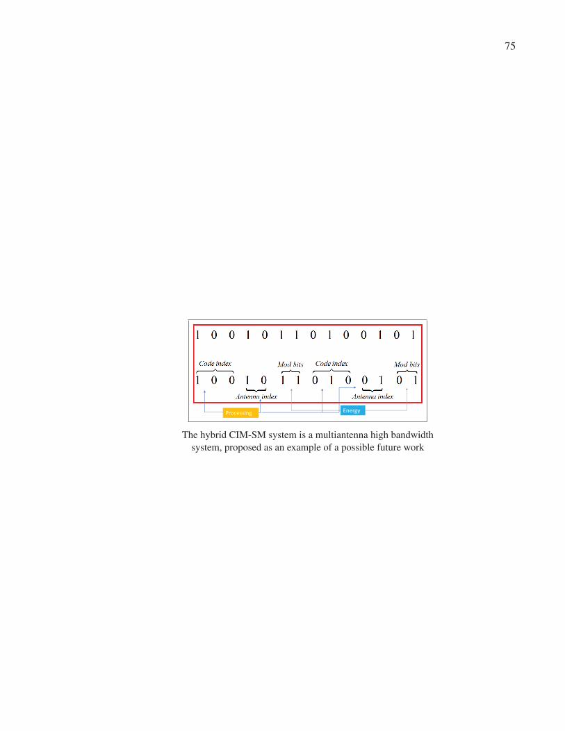
75
The hybrid CIM-SM system is a multiantenna high bandwidth
system, proposed as an example of a possible future work


APPENDIX I
PERFORMANCE COMPARISON OF SPATIAL MODULATION DETECTORSUNDER CHANNEL IMPAIRMENTS
Ebrahim Soujeri1 and Georges Kaddoum1
1 Department of Electrical Engineering, École de Technologie Supérieure,
1100 Notre-Dame West, Montreal, Quebec, Canada H3C 1K3
Paper published in IEEE International Conference on Ubiquitous Wireless Broadband(ICUWB), October 2015.
Abstract
Spatial modulation (SM) is a multiple antenna transmission approach that uses the index of the
transmitting antenna for delivering information data. The choice on the transmitting antenna
depends on the incoming bit sequence and has a random nature. The receiver estimates the
transmitted symbol and the active transmit antenna index and uses both estimations to retrieve
the original information bits. For best reception, individual channel links between transmit
and receive antenna pairs must be unique. In fact, correct reception totally depends on the
uniqueness of channel coefficients. Incorrectly interpreting channel state information at the re-
ceiver causes the BER performance to degrade and the detection to fall short. In this paper, we
develop a channel model that incorporates both correlated and imperfect channel state informa-
tion and use this model to study the bit-error-ratio (BER) performance of most widely used SM
detectors, namely the minimum mean square error, the maximum likelihood and the optimum
detector in flat Rayleigh fading channels to examine the sensitivity these detectors exhibit to
the presence of either channel correlation or imperfect channel state information. The capacity
of SM system is studied in comparison to other multiple-input multiple-output techniques and
the influence of channel impairments on the overall system capacity is observed.

78
1. Introduction
Spatial Modulation (SM) is a recently developed low-complexity Multiple-Input Multiple-
Output (MIMO) scheme where the information bitstream is divided into blocks of length
(nt +m) = log2(NtM) bits, where Nt is the number of transmit antennae and M is the size
of the signal set Mesleh et al. (2006a, 2008). In SM, only one antenna out of Nt antennae is
active during a transmission time. In each block of (nt +m) bits, m = log2(M) bits select a
symbol from an M-ary signal set (such as M-QAM or -PSK) and nt = log2(Nt) bits select an
antenna out of Nt transmit antennae to accomplish transmission. In this configuration, transmit
antenna indices will be j = 1,2,3, ...,Nt .
The throughput achieved by this scheme is R = log2(NtM) bpcu. Therefore, the SM scheme
achieves an increase in the spectral efficiency of log2(M) bits over single-antenna systems. In
order to achieve higher throughputs, either Nt or M, or both need to be increased which renders
this scheme suitable for low and moderately high spectral efficiencies. One of the important
benefits of this scheme is that it is free from inter-channel interference (ICI) by virtue of acti-
vating a single transmit antenna at a time. In the context of the scope of this paper, the impact
of imperfect CSI on a multiple-input multiple-output (MIMO) system with interference has
been studied in Lee et al. (2012), the performance of a MISO system with maximum likeli-
hood (ML) detection and full CSI at the receiver is considered in Di Renzo & Haas (2010) and
the effect of channel estimation errors on the performance of SM with ML detection is exam-
ined in Mesleh & Ikki (2012). Since the uniqueness of channel coefficients is a requirement
for correct detection in SM system and because the system performance entirely depends on
the peculiarity of channel coefficients, inaccurately depicting channel state information at the
receiver leads to BER performance degradation.
In this paper, a channel model that incorporates both correlated and imperfect channel state
information at the receiver is developed. The developed model is then used to study the bit-
error-ratio (BER) performance of three most widely used SM detectors, namely the minimum

79
mean square error (MMSE), the ML and the optimum detector (OD) in flat Rayleigh fading
channels to ponder the extent to which the BER performance deviates from the ideal case with
perfect knowledge of channel state information (CSI). The influence of channel impairments
on the capacity of the SM system under the developed model is also investigated. The rest of
this paper is organized as follows: In Section 2, SM system model is presented. In Section 3,
an explanation regarding the SM detectors on which this study focuses is presented. Section 4
studies channel impairments. Capacity of SM is provided in Section 5. Simulation results are
presented in Section 6 and discussions and conclusions are given in Section 7.
2. SM System Model
The SM system consists of a MIMO wireless link with Nt transmit and Nr receive antennae,
and a random sequence of independent bits b =[b1 b2 · · · bNt
]that enter an SM mapper
or interleaver encoder, where groups of m + nt bits are mapped into a constellation vector
x =[x1 x2 · · · xNt
]Tand are transmitted at a time. In SM, only one antenna is active during
transmission and only one single entry is non-zero in x, i.e. the entry (or index) of the chosen
antenna will be nonzero. Fig. I-1 gives a pictorial representation of this scheme. Note that the
mapping table in Fig. I-1 is for the binary transmission case and is put there for illustration
simplicity.
2.1 The Wireless Channel
The SM signal is transmitted over an Nr ×Nt wireless channel H and experiences an Nr−dim
additive white Gaussian noise (AWGN) n =[n1 n2 · · · nNr
]T. The channel matrix H ∈
CNr×Nt has entries given by
H =
⎡⎢⎢⎢⎢⎢⎢⎣h11 h12 · · · h1Nt
h21 h22 · · · h2Nt
......
. . ....
hNr1 hNr2 · · · hNrNt
⎤⎥⎥⎥⎥⎥⎥⎦ (A I-1)

80
Figure-A I-1 The spatial modulation system
where h ji is a complex fading coefficient that connects the ith transmit antenna to the jth receive
antenna and is modelled as independent and identically distributed (iid) zero-mean complex
Gaussian (ZMCG) random variables with unit variance. Knowing that SM uses symbol indices
as well as antenna indices as means to send information, the symbol index combined with
the antenna index make up the SM mapper which outputs a constellation vector that has the
following form
x jq =
⎡⎣0 0 · · · xq · · · 0 0
↑jth position
⎤⎦T
(A I-2)
where xq is the qth symbol from the M-ary constellation X and j is the index of the activated
antenna. Therefore, only the jth antenna remains active transmitting the qth symbol. The output
of the SM channel when the qth symbol is transmitted on the jth antenna is expressed as
y =√
Es h jxq +n (A I-3)
where Es is the symbol energy defined as Es � mEb, h j denotes the activation of the jth column
of H for a randomly chosen j during each transmission period, y ∈ CNr×1 is the received

81
samples vector and n ∈ CNr×1 is the additive noise vector, where each element is assumed to
be iid ZMCG random variable with variance σ2n . From this point onwards and for the sake of
simplicity, we assume that the symbol energy√
Es is embedded in the transmitted symbol xq
such that the expression√
Es xq reduces to xq.
3. SM Detector Types
As indicated earlier, we consider the performance of the most widely used three types of SM
detectors, namely the MMSE, the ML and the OD receivers. In MMSE, the antenna index is
estimated first, then the transmitted symbol is detected Mesleh et al. (2006a). In both ML and
OD, a joint detection of antenna index and transmitted symbol is carried out. The size of the
search space in MMSE is Nt +M while it is NtM in ML and OD.
3.1 Minimum Mean Square Error Detection
The MMSE detector carries out detection at two consecutive stages; first, the antenna index
is estimated, then the transmitted symbol is detected Mesleh et al. (2006a). The transmitted
signal is received by Nr receive antennae. After demodulation at the kth antenna, the complex
conjugate of the kth row of H is multiplied by y resulting in
gk = hHk y (A I-4)
for k = 1,2, · · · ,Nt . Placing the outcome for all transmit antennae coefficients in a complex
vector such that
g =[g1 g2 · · · gNt
](A I-5)
The transmit antenna number j is the index (position) of the element in g whose absolute value
is maximum Mesleh et al. (2006a)
j = argmaxj
|g| (A I-6)
The antenna index (number) estimate is the position of the maximum absolute value of all
elements in the vector g. As can be noticed in the SM transmission, H reduces to h j by virtue

82
of having only one active antenna at a time, i.e. the jth antenna. The search argued in Eq. (A
I-6) corresponds to finding the element of greatest magnitude in the spatial domain among a
set of Nt elements. Assuming that the estimate of the transmit antenna number is correct, the
transmitted symbol at this instant can be estimated by finding the distance between g j and each
signal constellation point. That is to say, the constellation point that has minimum distance to
g j is considered to be the winner.
q = argminq
|g j − xq| (A I-7)
3.2 Maximum Likelihood Detection
The ML detection which is based on maximum likelihood sequence estimation (MLSE) is a
detection scheme that calculates the minimum Euclidean distance between the received signal
and all possibly transmitted sequences. An example of such a detection scheme and the search
for the closest lattice point for MIMO is performed in Damen et al. (2003) and for SM-MIMO
is carried out in Legnain et al. (2013). ML estimates the combination of antenna index and
transmit symbol at one shot, given by the expression
[j, q
]= argmin
j,q‖y−h j xq‖2
(A I-8)
where || · ||F denotes the Frobenius norm which is defined as the sum of the absolute squares of
its argument Golub & Van Loan (2012). The ML detector jointly estimates the antenna index
and the transmitted symbols by searching over all possible values of the constellation vector
space X and channel matrix H. It must be noted, however, that the complexity of this detector
increases exponentially with the modulation order M and number of transmit antennae Nt as a
natural consequence for the expansion of the search space given by NtM.

83
3.3 Optimal Detection
Like the ML detector, the optimum detector (OD) also performs a joint detection of antenna in-
dices and transmitted symbols, however, it follows slightly a different rule than the ML detector
and is given by
[ j, q] = argminj,q
(||h j||2F |xq|2 −2Re{yHh j xq})
(A I-9)
where the optimal detection is based on the maximum likelihood detection parameters exclud-
ing the term yHy.
4. Channel Impairments
The channel impairments we attempt to study in this work are classified in two categories.
First we study the effect of channel estimation errors (imperfections) on the performance of
SM detectors, then we investigate the influence of channel correlation. The former is the case
in which the estimated channel coefficients are contaminated with noise. The latter is the case
where channel coefficients are correlated.
4.1 Erroneous Channel
Channel estimation is the most crucial and important part of SM detection process. We assume
the presence of either error-free (perfect) or erroneous (imperfect) channel estimations. Since
avoiding CSI errors is difficult in practical systems, we assume the existence of both ampli-
tude and phase errors in the estimated CSI. We define erroneous CSI such that the following
relationship between the estimated and the correct channel coefficients at the kth receiver holds
hk = ρ hk +(1−ρ) ε1×Nt (A I-10)

84
where ε is a normal distributed random variable with zero mean and unit variance. The coeffi-
cient 0<ρ<1 is a correspondence factor that determines the resemblance of the estimated CSI
to the actual one. Perfect CSI estimation is achieved when ρ = 1, i.e. when 1−ρ = 0.
4.2 Correlated Channel
In the context of our work, we define channel correlation to be the interference of the entries
of the channel matrix with each other such that the correlated channel becomes
H = HΔ, (A I-11)
where
Δ ∈ RNt×Nt
is a Toepltiz matrix with the value 1−δ in the diagonal elements and the value δ in the super-
diagonal and sub-diagonal elements. The Δ matrix takes the form given below for Nt = 4
Δ =
⎡⎢⎢⎢⎢⎢⎢⎣(1−δ ) δ 0 0
δ (1−δ ) δ 0
0 δ (1−δ ) δ
0 0 δ (1−δ )
⎤⎥⎥⎥⎥⎥⎥⎦ (A I-12)
where 0 < δ � 1. Channel coefficients are said to be perfectly uncorrelated when δ = 0, i.e.
when 1−δ = 1.
85
4.3 Erroneous and Correlated Channel
We consider the generalized case where the channel coefficients are first correlated with each
other, then undergo certain amount of contamination with noise. We have used the following
model to incorporate both correlation and contamination with noise
H = ρ HΔ+(1−ρ)εNr×Nt . (A I-13)
It is clear that the overall channel model H depicted in Eq. (A I-13) is governed by the two
parameters δ and ρ each with the properties described aforetime and is the the result of having
H be first correlated by Δ in the fashion expressed in Eq. (A I-12) and then contaminated by
noise in a similar manner to Eq. (A I-10).
5. Capacity of SM
The capacity of MIMO, single-input multiple-output (SIMO) and multiple-input single-output
(MISO) systems are well discussed in Chapter 8 of David & Pramod (2005) where the capaci-
ties of these systems are compared and graphically presented for n = 1,2, · · · ,16 for the n×n
MIMO, n× 1 SIMO and 1× n MISO cases where n = Nt = Nr. In this work, we reproduce
the capacities described and shown in Fig. 8.6 on page 345 of David & Pramod (2005) and
we base our argument on capacity by adding the capacity of SM to this collection in order
to have a better outlook on the location of SM, in terms of capacity, among the other MIMO
technologies mentioned here.
5.1 Capacity Calculation
In order to calculate the capacity of the SM system, the MIMO capacity approach will not apply
because the antenna number represents added information. Furthermore, the antenna pattern
is considered as spatial constellation and not as source of information. Thus, concerning com-
puting the SM capacity, the conventional information theory approach will be used Prisecaru
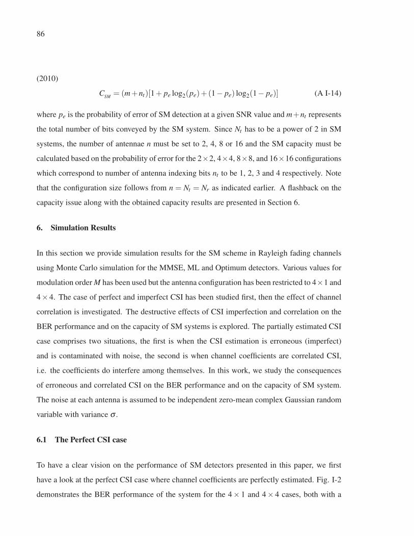
86
(2010)
CSM = (m+nt)[1+ pe log2(pe)+(1− pe) log2(1− pe)] (A I-14)
where pe is the probability of error of SM detection at a given SNR value and m+nt represents
the total number of bits conveyed by the SM system. Since Nt has to be a power of 2 in SM
systems, the number of antennae n must be set to 2, 4, 8 or 16 and the SM capacity must be
calculated based on the probability of error for the 2×2, 4×4, 8×8, and 16×16 configurations
which correspond to number of antenna indexing bits nt to be 1, 2, 3 and 4 respectively. Note
that the configuration size follows from n = Nt = Nr as indicated earlier. A flashback on the
capacity issue along with the obtained capacity results are presented in Section 6.
6. Simulation Results
In this section we provide simulation results for the SM scheme in Rayleigh fading channels
using Monte Carlo simulation for the MMSE, ML and Optimum detectors. Various values for
modulation order M has been used but the antenna configuration has been restricted to 4×1 and
4×4. The case of perfect and imperfect CSI has been studied first, then the effect of channel
correlation is investigated. The destructive effects of CSI imperfection and correlation on the
BER performance and on the capacity of SM systems is explored. The partially estimated CSI
case comprises two situations, the first is when the CSI estimation is erroneous (imperfect)
and is contaminated with noise, the second is when channel coefficients are correlated CSI,
i.e. the coefficients do interfere among themselves. In this work, we study the consequences
of erroneous and correlated CSI on the BER performance and on the capacity of SM system.
The noise at each antenna is assumed to be independent zero-mean complex Gaussian random
variable with variance σ .
6.1 The Perfect CSI case
To have a clear vision on the performance of SM detectors presented in this paper, we first
have a look at the perfect CSI case where channel coefficients are perfectly estimated. Fig. I-2
demonstrates the BER performance of the system for the 4× 1 and 4× 4 cases, both with a

87
modulation order M = 8. As expected and observed in Fig. I-2, the optimum detector shows
superior performance in comparison to its rivals in this scenario and antenna diversity plays its
BER enhancement role as expected.
Figure-A I-2 BER performance of SM with perfectly
estimated CSI for 4×1 and 4×4 configurations
6.2 The Imperfect CSI case
In this section, we study the performance of SM detectors with imperfect channel coefficients
as narrated in Eq. (A I-10). The BER performance of SM detectors for ρ = 0.85 and ρ = 0.7
is shown in Fig. I-3. As obsreved, the BER performance deteriorates with decreased value of
the correspondence factor ρ . The ML detector seems to be more susceptible to noise since it
contains more noisy terms that challenge the minimum Euclidean distance.
6.3 The Correlated CSI case

88
Figure-A I-3 BER performance of SM with imperfect CSI for a 4×4 configuration with M = 8
The BER performance of the SM system with correlated channel coefficients as described by
the Δ matrix in Eq. (A I-12) is considered here. The performance of SM detectors for δ = 0.15
and δ = 0.3 is shown in Fig. I-4. As can be observed in this figure, the BER performance
deteriorates as the correlation value increases.
6.4 Correlated and Imperfect CSI
The system has been tested in accordance with the inclusive model we propose in Eq. (A I-13)
with M = 8, Nt = Nr = 4. A 3-D view of the BER using OD SM versus δ and 1−ρ is shown
in Fig. I-5 for 0 ≤ δ ≤ 0.5 and 0 ≤ 1− ρ ≤ 0.5. The reason why we chose the optimum
detector is because this detector proved to outperform the rival detectors while it maintained
more robustness against both imperfection and correlation. As observed here, both factors ρ
and δ exhibit a similar destructive trend. The relationship between ρ , δ and the noise variance
is left for future analysis.
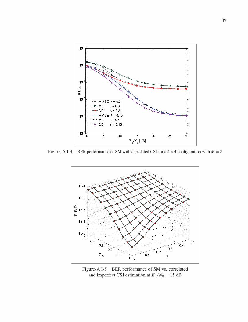
89
Figure-A I-4 BER performance of SM with correlated CSI for a 4×4 configuration with M = 8
Figure-A I-5 BER performance of SM vs. correlated
and imperfect CSI estimation at Eb/N0 = 15 dB
90
6.5 Capacity Issues
Having studied the influence of imperfect and correlated CSI on the system performance, we
will have a look at the capacity degradation under the presence of ρ and δ . Based on our results,
the OD has proved to achieve the best BER performance while it exhibits most robustness
against channel imperfections and correlation, so the probability of error in Eq. (A I-14) will
be based on optimal detection. Furthermore, the signal to noise ratio will be fixed at 0 dB
since the MIMO, MISO and SIMO systems of Prisecaru (2010) are evaluated at this value. In
Fig. I-6 the capacities originally given in David & Pramod (2005) were reproduced and the
capacity of SM was then calculated and added in the described fashion. Since MIMO, SIMO
and MISO evaluations are done at perfect CSI, i.e. ρ = 1,δ = 0, the capacity of SM at these
values corresponds to the perfect CSI case and represents the capacity of SM in comparison
with other MIMO technologies. As seen in Fig. I-6, with imperfect and correlated coefficients,
capacity of the SM system drops as a consequence of the BER performance decline at no
surprise. The capacity of SM deteriorates even more as ρ and δ take farther distances from the
ideal values. More on MIMO capacity issues may be looked up in Foschini (1996) and Kalis
et al. (2008).
7. Discussions and Conclusions
In this work, we have developed a general model for channel impairments that incorporates
channel imperfection and channel correlation. The developed model is then used to study
the effects of channel impairments on the BER performance of three most widely used SM
receivers, namely the MMSE, ML and OD receivers. Moreover, the influence of channel im-
pairments on the capacity of the SM system has also been investigated. Even though numerical
calculations are mainly based on a 4×4 SM system configuration, the results obtained may be
generalized to any accommodating configuration. Furthermore, our results reveal that the BER
performance of SM detectors under study deteriorate with channel imperfections especially in
high SNR regions. In fact, the performance of the ML is very fragile and sensitive to either
correlated or imperfect channel coefficients while MMSE and OD do better in such situations.

91
Figure-A I-6 Capacities of MIMO, SM, SIMO and MISO channels
Given the lower complexity of MMSE compared to OD and the convergence of their BER
performance at high SNR values, the MMSE might be a preferred candidate for higher power
scenarios where simplicity matters. However, at lower SNR, the OD becomes a more suitable
choice. Fundamental complexity concepts are provided in Bai et al. (2014) while more related
complexity discussions are found in Mesleh et al. (2006a, 2008); Kaddoum & Soujeri (2015)
and is not repeated here. The information theory-based calculation of the SM capacity carried
out in this work confirms and approves this fact. Consequently, channel impairments cause the
SM system capacity to drop as a reasonable and logical aftermath of the rise in the probability
of error. Therefore, CSI is a phenomenon that can not be always assumed to be perfect because
of the serious impacts it has on the BER performance and on the capacity of the SM system.
Finally, we observe that SM is sensitive to both imperfect and correlated channels.

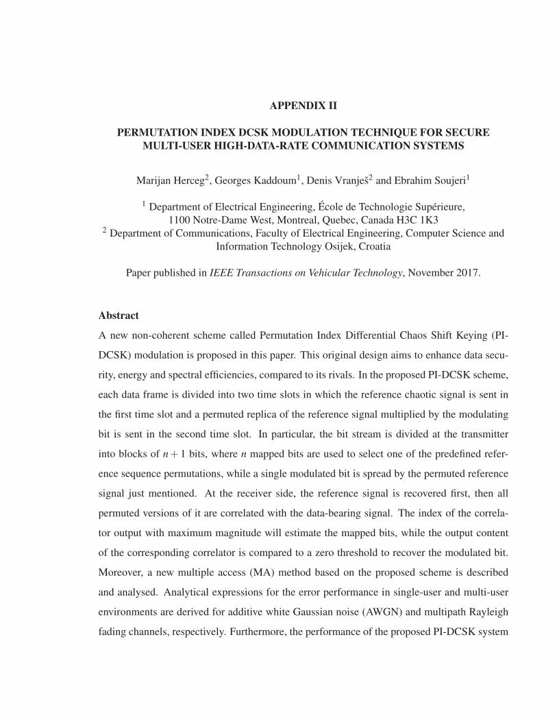
APPENDIX II
PERMUTATION INDEX DCSK MODULATION TECHNIQUE FOR SECUREMULTI-USER HIGH-DATA-RATE COMMUNICATION SYSTEMS
Marijan Herceg2, Georges Kaddoum1, Denis Vranješ2 and Ebrahim Soujeri1
1 Department of Electrical Engineering, École de Technologie Supérieure,
1100 Notre-Dame West, Montreal, Quebec, Canada H3C 1K32 Department of Communications, Faculty of Electrical Engineering, Computer Science and
Information Technology Osijek, Croatia
Paper published in IEEE Transactions on Vehicular Technology, November 2017.
Abstract
A new non-coherent scheme called Permutation Index Differential Chaos Shift Keying (PI-
DCSK) modulation is proposed in this paper. This original design aims to enhance data secu-
rity, energy and spectral efficiencies, compared to its rivals. In the proposed PI-DCSK scheme,
each data frame is divided into two time slots in which the reference chaotic signal is sent in
the first time slot and a permuted replica of the reference signal multiplied by the modulating
bit is sent in the second time slot. In particular, the bit stream is divided at the transmitter
into blocks of n+ 1 bits, where n mapped bits are used to select one of the predefined refer-
ence sequence permutations, while a single modulated bit is spread by the permuted reference
signal just mentioned. At the receiver side, the reference signal is recovered first, then all
permuted versions of it are correlated with the data-bearing signal. The index of the correla-
tor output with maximum magnitude will estimate the mapped bits, while the output content
of the corresponding correlator is compared to a zero threshold to recover the modulated bit.
Moreover, a new multiple access (MA) method based on the proposed scheme is described
and analysed. Analytical expressions for the error performance in single-user and multi-user
environments are derived for additive white Gaussian noise (AWGN) and multipath Rayleigh
fading channels, respectively. Furthermore, the performance of the proposed PI-DCSK system

94
is analysed and compared with other non-coherent chaotic modulation schemes and is found
to be promising.
1. Introduction
Chaotic signals have gained increasing popularity for usage in spread spectrum communica-
tion systems in the last two decades. The main reason is that such signals can be easily gener-
ated and have properties like wideband spectrum, impulse-like auto-correlation and low cross-
correlation values Lau & Tse (2003). These properties are very important for better multiple
access performance, higher resistance to jamming or interference and more immunity against
multipath effects. Besides, its non-periodic nature reinforces the transmission security when,
this latter, is used in a coherent fashion.
During previous researches numerous coherent and non-coherent chaos-based communication
schemes have been proposed. The main drawback of coherent systems like chaos-shift-keying
(CSK) Dedieu & Kennedy (1993) is the synchronization of chaotic signals at the receiver,
which is a challenging task in noisy channels.
Enjoying excellent correlation properties of chaotic signals, non-coherent modulation schemes
based on transmitted reference (TR) Rushforth (1964) method have been increasingly stud-
ied by the scientific community. The first non-coherent modulation based chaotic scheme is
the differential chaos shift keying (DCSK) Kolumbán et al. (1996) and its constant power
frequency-modulated DCSK version (FM-DCSK) Kolumbán et al. (1997a). In DCSK, every
bit duration is split into two time slots. In the first slot, a reference chaotic sequence is sent,
while in the second slot, a data-modulated time-delayed reference chaotic sequence is sent.
At the receiver, the reference sequence is correlated with the data modulated sequence in or-
der to recover the transmitted bit. The main advantages of such an approach are avoidance of
chaotic sequence recovery, inexistence of a channel state estimator at the receiver, resistance
to multi-path interferences and simple implementation. However, the main drawbacks of such
an approach are low data rate, high energy consumption as well as the usage of wideband RF

95
delay lines, which are not easy to implement in CMOS technologyXu et al. (2011). It should
also be mentioned that the RF delay line is an issue only in analogue implementations, while
in digital implementations, such as FPGA or system-on-chip (SoC), is no longer an issue.
Recently, some DCSK improvements on energy efficiency and data rate have been addressed
in many works. In this vein, high-efficiency DCSK (HE-DCSK) is proposed in Yang & Jiang
(2012). In HE-DCSK, bandwidth efficiency is doubled and chaotic signal re-transmission is re-
duced, which adds to the transmitted signal data security in comparison with DCSK. However,
it needs four delay lines and is thus not suitable for fast fading channels. In order to reduce
the number of needed delay lines in HE-DCSK, reference-modulated DCSK (RM-DCSK) has
been proposed in Yang & Jiang (2013). In RM-DCSK, the reference chaotic signal also serves
as a data bearer, which enhances bandwidth efficiency. To reduce the noise variance at the
receiver, a noise-reduction DCSK (NR-DCSK) is proposed in Kaddoum & Soujeri (2016).
In NR-DCSK, multiple replicas of the reference chaotic signal are sent and averaged at the re-
ceiver in order to reduce the noise interference prior to correlation with the data bearing chaotic
sequence. Short-reference DCSK (SR-DCSK) is proposed in Kaddoum et al. (2016a) with the
target of reducing delay lines. In SR-DCSK, a reference chaotic signal is shortened to less
than a half of the bit duration and multiple replicas of the reference signal are used to spread
the data. Such an approach improves energy efficiency and boosts data rate without adding
hardware complexity. To improve spectral efficiency, quadrature chaos-shift keying (QCSK) is
proposed in Galias & Maggio (2001). In QCSK, the reference chaotic signal is sent in the first
slot, while a linear combination of the Hilbert transform of the reference signal and a delayed
version of the reference signal are used to map two bits in the second slot. The non-coherent
chaos-based permuted sequence technique is introduced in Lau & Tse (2009), in which per-
mutations of the reference signal are used for mapping additional bits per transmitted symbol.
Furthermore, to mitigate the effect of multipath fading and to achieve a full-scale diversity
gain without the need to channel state information, space-time block codes (STBC) are used in
combination with DCSK in Chen et al. (2013).

96
To avoid the usage of wideband RF delay lines and double the data rate, the authors in Kad-
doum et al. (2015a) have proposed an improved DCSK (I-DCSK) in which a time-reversal
operation on the reference sequence is used to separate the data and reference sequences, and
the resultant symbol is transmitted in one time slot rather than two. Furthermore, the binary
code-shifted DCSK (CS-DCSK) in which reference and data chaotic sequences are separated
by Walsh codes instead of time delay multiplexing, is presented in Xu et al. (2011). Two multi-
level versions of CS-DCSK, called generalized CS-DCSK (GCS-DCSK) and its improved ver-
sion multi-level CS-DCSK (MCS-DCSK) are presented in Xu et al. (2012) and Huang et al.
(2016), respectively. In high-data rate CS-DCSK (HCS-DCSK) Kaddoum & Gagnon (2012),
different chaotic sequences are used instead of Walsh codes in order to separate the reference
and data sequences. However, such approaches need chaotic sequence synchronization at the
receiver side. The implementation of DCSK-based communication systems in ultra-wideband
(UWB) applications and cooperative communications (CC) is analysed in Fang et al. (2016)
and Chen et al. (2016), respectively.
Multi-level, multi-carrier DCSK (MC-DCSK) in which the reference chaotic signal is sent
over a predefined subcarrier frequency, while multiple modulated data streams are sent over
the remaining orthogonal subcarriers was introduced in Kaddoum et al. (2013a). Despite the
improvements achieved by such an approach with respect to energy efficiency and data rate, it
demands large bandwidth.
Recently, the combination of index modulation (IM) and MC-DCSK, named carrier index
DCSK (CI-DCSK) is proposed in Cheng et al. (2016). In CI-DCSK, energy and spectral effi-
ciency are enhanced by mapping a part of the bits in the subcarrier indices, i.e. to determine
the subcarriers that will be active, while the remaining bits are conveyed by DCSK through
these active carriers. To allow multiple-access and reduce bandwidth demands of MC-DCSK,
a multi-user orthogonal-frequency-division-multiplexing DCSK (MU-OFDM-DCSK) is pro-
posed in Kaddoum (2016a). In MU-OFDM-DCSK, the spreading operation is performed in
the time domain over multiple orthogonal frequencies. Each user is dedicated a set of pre-
defined frequencies from multiple available frequencies, to transmit reference chaotic signals,

97
while the remaining frequencies are shared with the other users to transmit multiple bits. In
Kaddoum et al. (2013a) and Cheng et al. (2016), the reference and data chaotic sequences are
orthogonal over a chip time (the time duration of one chaotic sample), which requires the car-
rier time period to be less than the chip period. To reduce the demand on carrier frequencies, the
frequency-translated DCSK (FT-DCSK) is proposed in Herceg et al. (2016). In FT-DCSK, the
orthogonality between reference and data chaotic sequences is sustained over a symbol dura-
tion, using an orthogonal sinusoid carrier. FT-DCSK has a lower demand on carrier frequencies
compared to the methods proposed in Kaddoum et al. (2013a) and Cheng et al. (2016), but is
very sensitive to multipath time delays.
Recently, a novel M−ary modulation scheme called orthogonal multi-level DCSK (OM-DCSK)
is proposed Yang et al. (2016). In this configuration, each data-bearing signal is chosen from a
set of orthogonal chaotic sequences constructed from a reference signal. In order to increase the
number of signals contained in the orthogonal signal set, chaotic sequences and their Hilbert
transforms along with Walsh codes are used. The new scheme achieves a higher data rate, has
an augmented energy efficiency and scores a better bit error rate (BER) performance.
Inspired by the works of Lau & Tse (2009), Kaddoum et al. (2015a) and Yang et al. (2016),
we propose in this paper a multi-level permutation index DCSK (PI-DCSK) architecture. In
the PI-DCSK scheme proposed here, the input bit stream is divided into blocks of n+ 1 bits
transmitted at a time, where n bits are mapped in distinct permuted reference sequences and a
single bit is physically transmitted.
Here, the n mapped bits are used to select one of the predefined reference sequence permuta-
tions while a single bit called the modulated bit is spread by the selected permuted sequence.
This approach engages n+ 1 bits into each transmission instant. The remaining procedure in
PI-DCSK has a similar structure to the conventional DCSK, where each data frame is separated
into two time slots. In the first slot, the reference chaotic signal is sent and in the second slot,
the modulated bit is transmitted after being spread by the selected permuted sequence.

98
At the receiver side, the reference signal is first recovered, then all possible permuted versions
of it are correlated with the data bearing signal in order to find a maximum winner. The index
of the winner correlator will estimate the mapped bits, while its content is used to provide an
estimation of the modulated bit, after being compared to a zero threshold.
In the proposed design, the utilisation of 2n quasi-orthogonal signals achieves a modulation
order of M = 2n+1. This fact enhances data rate and energy efficiency while it keeps hardware
complexity relatively low. Furthermore, by eradicating the similarity between reference and
data bearing signals through using different permutations, the transmitted data security of the
proposed scheme is enhanced.
Furthermore, by exploiting the possible permutation set size, a new multiple access (MA)
method is proposed. Namely, for a given chaotic sequence length β , there is β !− 1 possible
permutations. In order to allow the MA in PI-DCSK, a distinct set of 2n permutations is used
for each user.
Compared to OM-DCSK, PI-DCSK avoids the usage of repeated chaotic generators (RCG),
Hilbert transforms or Walsh codes at the transmitter and receiver sides. The fact that we put
aside Walsh codes in PI-DCSK equips the proposed system with all properties of non-coherent
modulation.
To complete the proposed scheme, analytical bit error rate (BER) expressions over Rayleigh
multipath fading and additive white Gaussian noise (AWGN) channels, in both single-user and
multi-user environments are derived and validated versus simulation results. This is to show
the extent and level of accuracy of our analytical expressions. Finally, the performance of
PI-DCSK is analysed and compared with rival modulation techniques to show its superiority.
The remainder of this paper is organized as follows: In Section 2, the PI-DCSK system model is
briefly described. System analysis is provided in section 3. Performance analysis of PI-DCSK
system over AWGN and multipath Rayleigh channels is provided in section 4. Simulation
results and discussions are presented in Section 5 while conclusions are given in section 6.

99
2. PI-DCSK System Model
In this section, the transmitter and receiver architectures of the proposed system will be de-
scribed in detail.
2.1 The transmitter
The block diagrams of the proposed PI-DCSK system are presented in Figs. -II-1II-3, where
the transmitter is shown in Fig. II-1, the permutation process in Fig. II-2 and the receiver in
Fig. II-3. At the transmitter, the chaotic generator generates a chaotic sequence of β samples
that is used as a reference signal and is placed in the first time slot. This reference signal is
simultaneously loaded into a permutation block in order to generate different permuted replicas
of the original reference signal in the second time slot. Permutations are chosen in a way such
that it provides quasi-orthogonality between the generated permuted reference signal replicas.
An efficient method for generating a suitable set of permuted sequences with the aforemen-
tioned properties from the reference sequence is proposed in Lau et al. (2003). Moreover,
it is demonstrated that for a large spreading factor, permuted replicas of a chaotic signal are
quasi-orthogonal to each other Lau et al. (2003) such that
xPj(x)T ≈ 0, (A II-1)
Pi(x)Pj(x)T ≈ 0, for i �= j, (A II-2)
where x is a vector that contains β number of chaotic samples, Pj(·) represents the jth permuta-
tion operator and (·)T denotes transposition. Therefore, to carry n mapped bits, each transmitter
will generate 2n distinct permutations. By using a method described in Lau et al. (2003), the
β −1 permutations can be easily generated.

100
In particular, the input signed bit stream is divided at the PI-DCSK modulator into blocks
of n+ 1 bits. The ith block of bits of the kth user can be written as[a(k)i,1 ,a
(k)i,2 , · · · ,a(k)i,n+1
]=[
s(k)i ,a(k)i,n+1
], where s(k)i =
[a(k)i,1 ,a
(k)i,2 , · · · ,a(k)i,n
]is the vector of n mapped bits.
The mapped bits s(k)i select one of the 2n predefined permutations P(k) = {P(k)1 ,P(k)
2 , . · · · ,P(k)2n }.
Each element in s(k)i is a code vector generated by introducing a permutation of the original
reference sequence, as indicated earlier, while the modulated bit denoted by a(k)i,n+1 is spread
by the selected permuted sequence. Note that by using this mapping approach, the overall PI-
DCSK modulation order becomes equal to M = 2n+1 by using only M/2= 2n quasi-orthogonal
signals.
Furthermore, asynchronous data transmission of different users is assumed in this paper. In
addition, in the PI-DCSK system, each user uses a distinct set of M/2 permutations, such that
P(k) ∩P(u) = /0, for k �= u. In general, the overall number of possible permutations that can
be performed on a reference chaotic sequence of length β is equal to β !− 1. This allows us
to assign different sets of chaotic codes to a large number of users without having scarcity of
spreading sequences. In this vein, by permuting a reference signal of length β , the number of
users Nu in the PI-DCSK system is theoretically very large and is bound to
Nu ≤ (β !−1)/(M/2). (A II-3)
By using the proposed MA method, even for moderate spreading factors β , the possible number
of users grows to large values because the number of users in PI-DCSK system is proportional
to the different permutation that can be performed on the reference signal. This fact constitutes
a great advantage for multi-user scenarios. For example, for β = 50, the total number of
users turns to be Nu ≈ 1.52× 1064 users, for M = 4. However, it should be stated that not all
permutations, out from set of β !− 1 permutations, have a low cross-correlation property and
therefore, the system performance may degrade if permutations are not properly chosen.
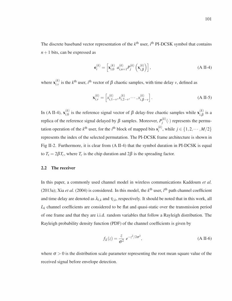
101
The discrete baseband vector representation of the kth user, ith PI-DCSK symbol that contains
n+1 bits, can be expressed as
e(k)i =[x(k)i,0 a(k)i,n+1P(k)
j
(x(k)i,β
)], (A II-4)
where x(k)i,v is the kth user, ith vector of β chaotic samples, with time delay v, defined as
x(k)i,v =[x(k)i,1−v,x
(k)i,2−v, · · · ,x(k)i,β−v
]. (A II-5)
In (A II-4), x(k)i,0 is the reference signal vector of β delay-free chaotic samples while x(k)i,β is a
replica of the reference signal delayed by β samples. Moreover, P(k)j (·) represents the permu-
tation operation of the kth user, for the ith block of mapped bits s(k)i , while j ∈ {1,2, · · · ,M/2}represents the index of the selected permutation. The PI-DCSK frame architecture is shown in
Fig II-2. Furthermore, it is clear from (A II-4) that the symbol duration in PI-DCSK is equal
to Ts = 2βTc, where Tc is the chip duration and 2β is the spreading factor.
2.2 The receiver
In this paper, a commonly used channel model in wireless communications Kaddoum et al.
(2013a); Xia et al. (2004) is considered. In this model, the kth user, lth path channel coefficient
and time delay are denoted as λl,k and τl,k, respectively. It should be noted that in this work, all
Lk channel coefficients are considered to be flat and quasi-static over the transmission period
of one frame and that they are i.i.d. random variables that follow a Rayleigh distribution. The
Rayleigh probability density function (PDF) of the channel coefficients is given by
fλ (z) =z
σ2e−z2/2σ2
, (A II-6)
where σ > 0 is the distribution scale parameter representing the root mean square value of the
received signal before envelope detection.
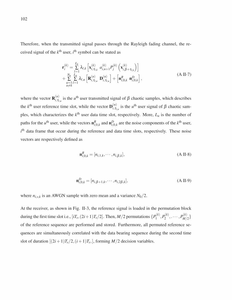
102
Therefore, when the transmitted signal passes through the Rayleigh fading channel, the re-
ceived signal of the kth user, ith symbol can be stated as
r(k)i =Lk∑
l=1λl,k
[x(k)i,τl,k
a(k)i,n+1P(k)j
(x(k)i,β+τl,k
)]+
Nu∑
u=1u�=k
Lu∑
l=1λl,u
[R(u)
i,τl,uD(u)
i,τl,u
]+
[nR
i,0,k nDi,0,k
],
(A II-7)
where the vector R(u)i,τl,u
is the uth user transmitted signal of β chaotic samples, which describes
the kth user reference time slot, while the vector D(u)i,τl,u
is the uth user signal of β chaotic sam-
ples, which characterizes the kth user data time slot, respectively. More, Lu is the number of
paths for the uth user, while the vectors nRi,0,k and nD
i,0,k are the noise components of the kth user,
ith data frame that occur during the reference and data time slots, respectively. These noise
vectors are respectively defined as
nRi,0,k = [ni,1,k, · · · ,ni,β ,k], (A II-8)
nDi,0,k = [ni,β+1,k, · · · ,ni,2β ,k], (A II-9)
where ni,v,k is an AWGN sample with zero mean and a variance N0/2.
At the receiver, as shown in Fig. II-3, the reference signal is loaded in the permutation block
during the first time slot i.e., [iTs,(2i+1)Ts/2]. Then, M/2 permutations {P(k)1 ,P(k)
2 , . · · · ,P(k)M/2
}of the reference sequence are performed and stored. Furthermore, all permuted reference se-
quences are simultaneously correlated with the data bearing sequence during the second time
slot of duration [(2i+1)Ts/2,(i+1)Ts, ], forming M/2 decision variables.

103
The corresponding decision variable at the output of the kth user, ith time slot, mth correlator
may be stated as
D(k)i,m = P(k)
m
(Lk∑
l=1λl,kx(k)i,β+τl,k
+Nu∑
u=1u�=k
Lu∑
l=1λl,uR(u)
i,β+τl,u+nR
i,β ,k
⎞⎠×
(Lk∑
l=1λl,ka(k)i,n+1P(k)
j (x(k)i,β+τl,k)
+Nu∑
u=1u �=k
Lu∑
l=1λl,uD(u)
i,τl,u+nD
i,0,k
⎞⎠T
,1 ≤ m ≤ M/2.
(A II-10)
ChaoticGenerator
PermutationBlock
PermutationSelector
Figure-A II-1 A block diagram of the PI-DCSK communication system transmitter
In order to determinate the matching permutation index, in the detector and decision logic
circuit, the magnitude of M/2 correlator outputs, are compared in order to find the largest
value
j = argmaxm
{∣∣∣D(k)i,m
∣∣∣} ,m ∈ {1,2, · · · ,M/2} . (A II-11)

104
Referencesequence
Data sequence
Permutation andtime delay
Figure-A II-2 A block diagram of the PI-DCSK communication frame architecture
Permutationblock
ControlUnit
Detector&
DecisonLogic
Figure-A II-3 A block diagram of the PI-DCSK communication system receiver
By estimating the index of the largest correlator’s output j, the receiver knows which permu-
tation is used and uses the index of that permutation to provide an estimation of the n mapped
bits. The physically modulated bit can then be recovered by computing the sign of the selected
correlator
a(k)i,n+1 = sgn(D(k)i, j). (A II-12)

105
In our analysis, we assume that the largest delay, over all possible user and path combinations
τmax is much shorter than duration of the reference signal, i.e.
0 < τmax << βTc. (A II-13)
where τmax = max(τl,k) for all k, l. With this assumption in hand, the inter symbol interference
(ISI) may be neglected.
3. System Analysis
In this section, a PI-DCSK system analysis regarding energy efficiency and data security is
provided. Furthermore, hardware complexity comparison with OM-DCSK is performed as the
two systems share similar hardware functionalities and properties.
3.1 Energy efficiency
Besides its simplicity and high spectral efficiency, another major advantage of the PI-DCSK is
its energy efficiency. In Kaddoum et al. (2013a), the authors have introduced the data-energy-
to-bit-energy ratio (DBR) as
DBR =Edata
Eb, (A II-14)
where Edata is the energy of data bearing signal, while Eb is the required total energy to carry
each bit. In the proposed PI-DCSK scheme, the symbol energy Es is expressed as
Es = Edata +Eref, (A II-15)
where Eref is the energy of the reference sequence. Since the data sequence is a permuted
version of the reference sequence, the reference and data energies are equal
Edata = Eref = Tc
β
∑k=1
x2i,k. (A II-16)

106
Thus, the PI-DCSK symbol energy is equal to
Es = 2Tc
β
∑k=1
x2i,k. (A II-17)
In fact, Es is used to transmit log2(M) = n+ 1 bits while Eref is used to carry the reference
signal. Therefore, in comparison to the conventional transmit reference scheme, the energy
required to transmit one bit would be
Eb =Es
log2(M)=
2Tc
log2(M)
β
∑k=1
x2i,k. (A II-18)
Subsequently, by using (A II-15), (A II-16), (A II-17) and (A II-18), the DBR in (A II-14) can
be rewritten as
DBR =Edata
Eb=
log2(M)
2. (A II-19)
Table II-1 shows the DBR of different chaotic modulations. As clearly indicated in (A II-14),
Table-A II-1 DBR comparison of different chaotic modulation techniques
Modulation DBRDCSK, CS-DCSK 1/2
HE-DCSK, RM-DCSK, QCSK, FT-DCSK 2/3
MCS-DCSK (M−2)/MMC-DCSK (M−1)/M
OM-DCSK, PI-DCSK log2(M)/2
the DBR can be simply denoted as the ratio of the number of bits per symbol to the number
of chaotic sequences needed to transmit that symbol. For example, in DCSK, two chaotic
sequences (reference and data) are used to transmit one bit. It can be seen from Table I that
the DBR values of both MC-DCSK and MCS-DCSK converge to unity for higher values of
M, while this ratio is logarithmic in the order of M for PI-DCSK and OM-DCSK, which is
advantageous. Further, in the proposed PI-DCSK system, the DBR is higher than unity because
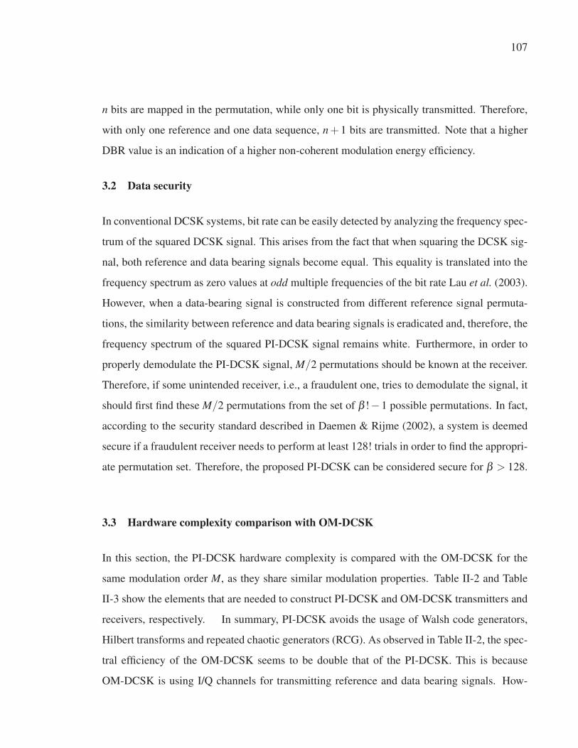
107
n bits are mapped in the permutation, while only one bit is physically transmitted. Therefore,
with only one reference and one data sequence, n+ 1 bits are transmitted. Note that a higher
DBR value is an indication of a higher non-coherent modulation energy efficiency.
3.2 Data security
In conventional DCSK systems, bit rate can be easily detected by analyzing the frequency spec-
trum of the squared DCSK signal. This arises from the fact that when squaring the DCSK sig-
nal, both reference and data bearing signals become equal. This equality is translated into the
frequency spectrum as zero values at odd multiple frequencies of the bit rate Lau et al. (2003).
However, when a data-bearing signal is constructed from different reference signal permuta-
tions, the similarity between reference and data bearing signals is eradicated and, therefore, the
frequency spectrum of the squared PI-DCSK signal remains white. Furthermore, in order to
properly demodulate the PI-DCSK signal, M/2 permutations should be known at the receiver.
Therefore, if some unintended receiver, i.e., a fraudulent one, tries to demodulate the signal, it
should first find these M/2 permutations from the set of β !−1 possible permutations. In fact,
according to the security standard described in Daemen & Rijme (2002), a system is deemed
secure if a fraudulent receiver needs to perform at least 128! trials in order to find the appropri-
ate permutation set. Therefore, the proposed PI-DCSK can be considered secure for β > 128.
3.3 Hardware complexity comparison with OM-DCSK
In this section, the PI-DCSK hardware complexity is compared with the OM-DCSK for the
same modulation order M, as they share similar modulation properties. Table II-2 and Table
II-3 show the elements that are needed to construct PI-DCSK and OM-DCSK transmitters and
receivers, respectively. In summary, PI-DCSK avoids the usage of Walsh code generators,
Hilbert transforms and repeated chaotic generators (RCG). As observed in Table II-2, the spec-
tral efficiency of the OM-DCSK seems to be double that of the PI-DCSK. This is because
OM-DCSK is using I/Q channels for transmitting reference and data bearing signals. How-

108
Table-A II-2 Transmitter complexity comparison of PI-DCSK and OM-DCSK
Transmitter PI-DCSK OM-DCSKAdders 0 1
Multipliers 1 2MSpectral efficiency log2(M)/(2β ) log2(M)/β
Additional Permutation block, Walsh code generator,
blocks single switch Hilbert transformer, RCG
Table-A II-3 Receiver complexity comparison of PI-DCSK and OM-DCSK
Receiver PI-DCSK OM-DCSKAdders M/2 M
Multipliers M/2 2MAdditional Permutation block Walsh code generator,
blocks Hilbert transformer
ever, PI-DCSK may also transmit using I/Q channels and achieve a similar spectral efficiency.
Furthermore, PI-DCSK transmitters do not need any adders at all and need a single multiplier
while OM-DCSK transmitters need an adder and 2M multipliers. Therefore, the complexity of
the proposed PI-DCSK is reduced to a great extent in comparison with OM-DCSK.
Similarly, the PI-DCSK receiver needs only half the number of adders and quarter the number
of multipliers needed by OM-DCSK, regardless of M. By the same token, permutation blocks
remain the only additional instrument needed on both sides of the PI-DCSK system.
4. Performance Analysis
In this section, the performance of PI-DCSK is evaluated, and analytical BER expressions
are derived for AWGN and multipath Rayleigh fading channels. We employ the Chebyshev
polynomial function in this work because of its simplicity and excellent statistical properties
Kaddoum et al. (2009a). For simplicity, the chip time Tc is set to unity. This polynomial is
known to proceed as
xi,k = 1−2x2i,k−1. (A II-20)
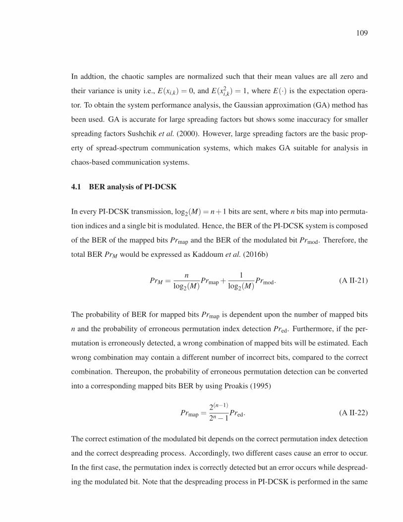
109
In addtion, the chaotic samples are normalized such that their mean values are all zero and
their variance is unity i.e., E(xi,k) = 0, and E(x2i,k) = 1, where E(·) is the expectation opera-
tor. To obtain the system performance analysis, the Gaussian approximation (GA) method has
been used. GA is accurate for large spreading factors but shows some inaccuracy for smaller
spreading factors Sushchik et al. (2000). However, large spreading factors are the basic prop-
erty of spread-spectrum communication systems, which makes GA suitable for analysis in
chaos-based communication systems.
4.1 BER analysis of PI-DCSK
In every PI-DCSK transmission, log2(M) = n+1 bits are sent, where n bits map into permuta-
tion indices and a single bit is modulated. Hence, the BER of the PI-DCSK system is composed
of the BER of the mapped bits Prmap and the BER of the modulated bit Prmod. Therefore, the
total BER PrM would be expressed as Kaddoum et al. (2016b)
PrM =n
log2(M)Prmap +
1
log2(M)Prmod. (A II-21)
The probability of BER for mapped bits Prmap is dependent upon the number of mapped bits
n and the probability of erroneous permutation index detection Pred. Furthermore, if the per-
mutation is erroneously detected, a wrong combination of mapped bits will be estimated. Each
wrong combination may contain a different number of incorrect bits, compared to the correct
combination. Thereupon, the probability of erroneous permutation detection can be converted
into a corresponding mapped bits BER by using Proakis (1995)
Prmap =2(n−1)
2n −1Pred. (A II-22)
The correct estimation of the modulated bit depends on the correct permutation index detection
and the correct despreading process. Accordingly, two different cases cause an error to occur.
In the first case, the permutation index is correctly detected but an error occurs while despread-
ing the modulated bit. Note that the despreading process in PI-DCSK is performed in the same

110
fashion as in conventional DCSK. In the second case, the permutation index is erroneously
estimated and the modulated bit is despread at the output of the wrong correlator. In this case,
the probability of correct detection will be simply equal to 12 . Consequently, the total BER of
modulated bits would be expressed as Kaddoum et al. (2016b)
Prmod = PrDCSK(1−Pred)+0.5Pred, (A II-23)
where PrDCSK is the BER for DCSK. Using (A II-21), (A II-22) and (A II-23), the detailed
form of PrM is revealed as
PrM = PrDCSK
log2(M) (1−Pred)+2n2n−1+(2n−1)2log2(M)(2n−1)Pred. (A II-24)
4.2 Erroneous permutation detection probability Pred
In order to estimate the transmitted permutation index, the PI-DCSK detector and decision
logic circuits select the maximum absolute value that is obtained at the output of one of the 2n
engaged correlators. For equiprobable transmitted permuted sequences, the error probability
conditioned on the kth user transmitted permutation P(k)j is given by
Pred = Pr(∣∣∣D(k)
i, j
∣∣∣ < max(∣∣∣D(k)
i,m
∣∣∣)∣∣∣P(k)j
),
for 1 ≤ mm�= j
≤ 2n,(A II-25)
where D(k)i,m and D(k)
i, j are the decision variables at the mth and jth correlator outputs, respec-
tively. In agreement with (A II-25), an erroneous permutation index estimation will occur if
the maximum absolute value of the decision variable∣∣∣D(k)
i,m
∣∣∣ is larger than∣∣∣D(k)
i, j
∣∣∣.As observed in (A II-10), the ith data block decision variable of the kth user at the output of
the mth correlator may follow two different patterns according to two hypotheses. The first
hypothesis is when the index of the correlator output M is equal to the transmitted permutation

111
index j, i.e j = m, where 1 ≤ m ≤ 2n, while the second hypothesis is when the index of the
correlator output does not match the index of transmitted permutation i.e., m �= j. Subsequently,
the decision variable defined in (A II-10) can be rewritten as
D(k)i,m =
⎧⎨⎩ S(k)i, j +MUI(k)i, j +N(k)
i, j , for m = j,
I(k)i,m +MUI(k)i,m +N(k)
i,m , for m �= j,(A II-26)
where S(k)i, j represents the desired signal, MUI(k)i, j and MUI
(k)i,m are the multi user interference
(MUI) components, N(k)i,m and N(k)
i, j are interference components generated by Gaussian noise
and I(k)i,m is the interference that models the cross-correlation of different permuted chaotic se-
quences. As such, the desired signal S(k)i, j can be rewritten from (A II-10) as
S(k)i, j =
(Lk∑
l=1λl,kP(k)
j
(x(k)i,β+τl,k
))×
(Lk∑
l=1λl,ka(k)i,n+1P(k)
j (x(k)i,β+τl,k)
)T
=Lk∑
l=1λ 2
l,ka(k)i,n+1P(k)j (x(k)i,β+τl,k
)P(k)j (x(k)i,β+τl,k
)T
+Lk∑
l=1
Lk∑
l′=1l′ �=l
λl,kλl′,ka(k)i,n+1P(k)j (x(k)i,β+τl′,k
)P(k)j (x(k)i,β+τl,k
)T
≈ a(k)i,n+1
β∑
k=1
Lk∑
l=1λ 2
l,k
(x(k)i,k−τl,k
)2.
(A II-27)
The last approximation in (A II-27) occurs as a result of the low auto-correlation property of
time-shifted chaotic sequences Kaddoum & Gagnon (2012)
x(k)i,τl,k
(x(k)i,τl′,k
)T ≈ 0, for l �= l′. (A II-28)
Therefore, the mean value of the ith data block at the jth correlator output, conditioned on a
given a(k)i,n+1, is
E(
D(k)i, j |a(k)i,n+1
)≈ a(k)i,n+1
log2(M)Eb2
Lk∑
l=1λ 2
l,k. (A II-29)

112
The approximation in (A II-29) arises from the assumption that τmax << βTc, which means
that ISI is negligible.
From (A II-10), MUI(k)i, j can be restated as
MUI(k)i, j =
Nu∑
u=1u�=k
Lu∑
l=1λl,uP(k)
j
(R(u)
i,β+τl,u
)
×⎛⎝ Lk
∑l=1
λl,ka(k)i,n+1P(k)j (x(k)i,β+τl,k
)+Nu∑
u=1u�=k
Lu∑
l=1λl,uD(u)
i,τl,u
⎞⎠T
+Lk∑
l=1λl,kP(k)
j
(x(k)i,β+τl,k
)⎛⎝ Nu∑
u=1u�=k
Lu∑
l=1λl,uD(u)
i,τl,u
⎞⎠T
.
(A II-30)
Due to the low cross-correlation between different permuted chaotic sequences, as described
in (A II-1) and (A II-2), the multi-user interference MUI(k)i, j can be modelled as a zero mean
Gaussian variable with variance
var(
MUI(k)i, j
)=
Nu∑
u=1u�=k
Lu∑
l=1
Lk∑
l′=1E
([λl,uλl′,ka(k)i,n+1P(k)
j
(R(u)
i,β+τl,u
)×
(P(k)
j (x(k)i,β+τl′,k))T
]2)
+Nu∑
u=1u�=k
Nu∑
u′=1u′ �=k
Lu∑
l=1
Lu∑
l′=1E
([λl,uλl′,u′P
(k)j
(R(u)
i,β+τl,u
)
×(
D(u′)i,τl′,u′
)T]2
)
+Lk∑
l=1
Nu∑
u=1u�=k
Lu∑
l′=1E
([λl,kλl′,uP(k)
j
(x(k)i,β+τl,k
)(D(u)
i,τl′,u
)T]2
)
≈ (Nu −1)log2
2(M)E2b
2β
Lk∑
l=1λ 2
l,k +(Nu −1)2 log22(M)E2
b4β .
(A II-31)
The last approximation in (A II-31) emerges from two standard assumptions. The first assump-
tion is that the expectation of the squared product of two different chaotic sequences is equal
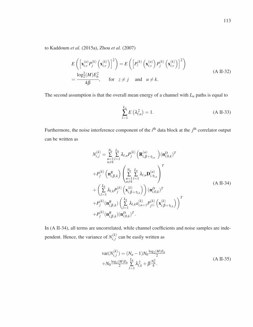
113
to Kaddoum et al. (2015a), Zhou et al. (2007)
E([
x(u)i,v P(k)j
(x(k)i,v
)]2)= E
([P(k)
z
(x(u)i,v
)P(k)
j
(x(k)i,v
)]2)
=log2
2(M)E2b
4β, for z �= j and u �= k.
(A II-32)
The second assumption is that the overall mean energy of a channel with Lu paths is equal to
Lu
∑l=1
E(λ 2
l,u)= 1. (A II-33)
Furthermore, the noise interference component of the ith data block at the jth correlator output
can be written as
N(k)i, j =
Nu∑
u=1u�=k
Lu∑
l=1λl,uP(k)
j
(R(u)
i,β+τl,u
)(nD
i,0,k)T
+P(k)j
(nR
i,β ,k
)⎛⎝ Nu∑
u=1u�=k
Lu∑
l=1λl,uD(u)
i,τl,u
⎞⎠T
+
(Lk∑
l=1λl,kP(k)
j
(x(k)i,β+τl,k
))(nD
i,0,k)T
+P(k)j (nR
i,β ,k)
(Lk∑
l=1λl,ka(k)i,n+1P(k)
j(i)
(x(k)i,β+τl,k
))T
+P(k)j (nR
i,β ,k)(nDi,0,k)
T .
(A II-34)
In (A II-34), all terms are uncorrelated, while channel coefficients and noise samples are inde-
pendent. Hence, the variance of N(k)i, j can be easily written as
var(N(k)i, j ) = (Nu −1)N0
log2(M)Eb2
+N0log2(M)Eb
2
Lk∑
l=1λ 2
l,k +β N20
4 .(A II-35)

114
Subsequently, the overall variance of the kth user, jth correlator decision variable is equal to
var(
D(k)i, j
)= var
(MUI
(k)i, j
)+var
(N(k)
i, j
)≈ (Nu −1)
log22(M)E2
b2β
Lk∑
l=1λ 2
l,k +(Nu −1)2 log22(M)E2
b4β
+(Nu −1)N0log2(M)Eb
2
+N0log2(M)Eb
2
Lk∑
l=1λ 2
l,k +β N20
4 .
(A II-36)
Furthermore, by using the properties mentioned in (A II-1) and (A II-2), the disturbance com-
ponent I(k)i,m in (A II-26) is approximately equal to zero, because of the low cross-correlation
between different permuted replicas
I(k)i,m =
(Lk
∑l=1
λl,kP(k)m (x(k)i,β+τl,k
)
)
×(
Lk
∑l=1
λl,ka(k)i,n+1P(k)j (x(k)i,β+τl,k
)
)T
≈ 0. (A II-37)
Using the same techniques as in (A II-31) and (A II-34), it can be easily shown that the vari-
ances of MUI(k)i,m and N(k)
i,m are equal to the variances of MUI(k)i, j and N(k)
i, j , respectively. Sub-
sequently, the overall variance of the kth user, mth correlator, where m �= j, decision variable
would be stated as
var(
D(k)i,m
)= var
(MUI
(k)i,m
)+var
(N(k)
i,m
)≈ (Nu −1)
log22(M)E2
b2β
Lk∑
l=1λ 2
l,k +(Nu −1)2 log22(M)E2
b4β
+(Nu −1)N0log2(M)Eb
2
+N0log2(M)Eb
2
Lk∑
l=1λ 2
l,k +β N20
4 .
(A II-38)
It is important to note that due to the absolute value operator, the mean value of∣∣∣D(k)
i, j
∣∣∣ is
independent of the modulated bit value and hence a(k)i,n+1 will be omitted in the derivations that
shall follow. The absolute values of the 2n − 1 random variables∣∣∣D(k)
i,m
∣∣∣ follow folded normal
distribution due to the fact that D(k)i,m is a zero mean Gaussian random variable Papoulis (1991).

115
Moreover, they are independent and hence, order statistics theory can be applied to compute
(A II-25) as Kaddoum et al. (2016b)
Pred = 1−∞∫
0
(F∣∣∣D(k)
i,m
∣∣∣(y))2n−1
f∣∣∣D(k)i, j
∣∣∣(y)dy, (A II-39)
where F∣∣∣D(k)i,m
∣∣∣(y) is the cumulative distribution function (CDF) of∣∣∣D(k)
i,m
∣∣∣ given as
F∣∣∣D(k)i,m
∣∣∣(y) = erf
⎛⎜⎜⎝ y√2var
(D(k)
i,m
)⎞⎟⎟⎠ , (A II-40)
where erf(·) is error function given as
erf(z) =z∫
0
2√π
e−x2dx. (A II-41)
More, f∣∣∣D(k)i, j
∣∣∣(y) is the probability density function (PDF) of the folded normally distributed
random variable∣∣∣D(k)
i, j
∣∣∣ which is given as
f∣∣∣D(k)i, j
∣∣∣(y) = 1√2πvar
(D(k)
i, j
)[
exp
(−
(y−E
(D(k)
i, j
))2
2var(
D(k)i, j
))
+ exp
(−
(y+E
(D(k)
i, j
))2
2var(
D(k)i, j
))
)].
(A II-42)

116
By substituting γb = Eb/N0
Lk∑
l=1λ 2
l,k in the expressions (A II-28), (A II-30) and (A II-33), we
may rewrite (A II-37) as
Pred = 1− 1√πW
∞∫0
(erf
(y√W
))2n−1
×[
exp
(−
(y− log2(M)
2 γb
)2
W
)
+ exp
(−
(y+ log2(M)
2 γb
)2
W
)]dy,
(A II-43)
where
W = (Nu −1)log2
2(M)β
(EbN0
γb +(Nu−1)
2
(EbN0
)2)
+(Nu −1)log2(M)EbN0
+ log2(M)γb +β2 .
(A II-44)
4.3 BER of modulated bit
In order to estimate the modulated bit, the despreading process is performed as in conventional
DCSK, by comparing the decision variable D(k)i, j to a zero threshold. Then, by using (A II-29)
and (A II-36), the bit error rate probability PrDCSK would be scripted as
PrDCSK =1
2erfc
⎛⎜⎜⎝ E(
D(k)i, j
)√
2var(
D(k)i, j
)⎞⎟⎟⎠ , (A II-45)
where erfc(x) = 1− erf(x) is the complementary error function. After some straightforward
operations, the instantaneous BER probability of DCSK system would be noted as
PrDCSK =1
2erfc
(log2(M)γb
2√
W
), (A II-46)
where W is as mentioned in (A II-45). The bit energy Eb can be assumed to be constant
for higher spreading factors β . Therefore, for Lk independent identically distributed (i.i.d.)

117
Rayleigh-fading channels, the PDF of instantaneous γb can be written as Proakis (1995)
f (γb, γc,Lk) =γLk−1
b
(Lk −1)! γLkc
exp
(−γb
γc
), (A II-47)
where γc is equal to
γc =Eb
N0E
(λ 2
l,k)=
Eb
N0E
(λ 2
j,k
), l �= j. (A II-48)
For dissimilar channels, however, the PDF of γb can be written as
f (γb) =Lk
∑l=1
ρl
γlexp
(−γb
γl
), (A II-49)
where
ρl =Lk
∏j=1j �=l
γl
γl − γ j. (A II-50)
Notice that for Lk = 1 and λ1,k = 1 the channel reduces to AWGN. Finally, the averaged BER
of the PI-DCSK system over multipath Rayleigh fading channels is given as
PrMfad =
∞∫0
PrM f (γb)dγb, (A II-51)
where the integral in (A II-51) is evaluated numerically.
5. Results and Discussions
In this section, the performance of the proposed PI-DCSK scheme is evaluated. In Monte-Carlo
simulation, the Chebyshev polynomial function is used for the generation of chaotic samples.
The performance analysis is carried out for AWGN and multipath Rayleigh fading channels.
To analyse the performance in multipath Rayleigh fading channels, three different channel
profiles are used. In the first channel model named CM1, a two-ray channel is used with an

118
average power gain of E(λ 2
1
)= E
(λ 2
2
)= 1/2. The second channel model named CM2 uses a
three-ray channel with the following gains E(λ 2
1
)= 4/7,E
(λ 2
2
)= 2/7,E
(λ 2
3
)= 1/7. Finally,
the third channel model named CM3 uses a five-ray channel with equal gains in all five paths,
i.e., E(λ 2
i)= 1/5, where i = 1, · · · ,5. For all multipath channel profiles, the delay spreads are
varying according to the uniform distribution between zero and a, where a � βTc.
5.1 Performance evaluation
In order to verify our theoretical derivations, the results obtained in (A II-51) are validated by
Monte Carlo simulation over AWGN, CM1, CM2 and CM3 channels. First, the averaged
20 40 60 80 100 120 140 160 180 2000
0.01
0.02
0.03
0.04
0.05
0.06
β
Ave
rage
d cr
oss−
corr
elat
ion
Figure-A II-4 Averaged cross-correlation of two
differently permuted sequences for various β
cross-correlations, defined as (A II-2), of two differently permuted sequences chosen as in Lau
et al. (2003), are shown in Fig. II-4, for different β . The cross-correlations are calculated and
averaged for 1000 different permuted sequences. It can be seen that the cross correlation is low
and exponentially decreases when the spreading factor increases.
In Figs. II-5-II-6, the influence of different modulation orders M on the PI-DCSK BER per-
formance over AWGN and the multipath Rayleigh fading channels CM1, CM2 and CM3 is
shown. As observed in these figures, there is a perfect match between the BER results obtained

119
0 2 4 6 8 10 12 14 16 18 2010−4
10−3
10−2
10−1
100
Eb/N0 (dB)
BER
M = 2M = 4M = 8M = 16Simulation
(a)
5 10 15 20 2510−3
10−2
10−1
100
Eb/N0(dB)
BER
M = 2 M = 4 M = 8 M = 16Simulation
(b)
Figure-A II-5 The influence of different modulation orders M on PI-DCSK
performance for β = 200 over (a) AWGN and (b) CM1 channels
by the analytical expressions of (A II-24) and (A II-51), versus Monte-Carlo simulation. Pre-
dictably, as M increases the PI-DCSK BER performance improves, which is due to the fact
that for higher M, more bits are mapped within a symbol for the same transmitted energy and,
hence, the required Eb/N0 needed to achieve a certain BER performance reduces. Furthermore,
it should be noticed that the BER performance of PI-DCSK for M = 2 is equal to the conven-
tional DCSK. For example, Fig. II-5 (a) clearly indicates that in order to achieve a BER of
10−3, the required Eb/N0 level for PI-DCSK must be approximately 3 dB lower for M = 16
in comparison to M = 2. In other words, when M increases, the number of bits per PI-DCSK

120
5 10 15 20 2510−4
10−3
10−2
10−1
100
BER
Eb/N0 (dB)
M = 2 M = 4 M = 8 M = 16Simulation
(a)
5 10 15 20 2510−4
10−3
10−2
10−1
100
Eb/N0 (dB)
BER
M = 2 M = 4 M = 8 M = 16Simulation
(b)
Figure-A II-6 The influence of different modulation orders M on PI-DCSK
performance for β = 200 over (a) CM2 and (b) CM3 channels
frame increases, while the transmitted energy remains constant. This explains the obtained
performance behaviour and proves the high energy efficiency of the system. Furthermore, it is
evident that there is a perfect match between theoretical and simulation results for all channel
models, which validates our analytical approach. In Figs. II-7-II-8 respectively, the influence
of different spreading sequence length β on the PI-DCSK BER performance over AWGN and
multipath Rayleigh fading channels CM1, CM2 and CM3 is shown. It is obvious that when β
increases the PI-DCSK BER performance degrades. This is owing to the fact that for higher
values of β , the noise×noise cross correlation terms in (A II-36) and (A II-38) become more

121
0 2 4 6 8 10 12 14 16 18 2010−4
10−3
10−2
10−1
100
Eb/N0 (dB)
BER
β = 50β = 100β = 150β = 200Simulation
(a)
5 10 15 20 2510−4
10−3
10−2
10−1
100
Eb/N0(dB)
BER
β = 50β = 100β = 150β = 200Simulation
(b)
Figure-A II-7 The influence of β on PI-DCSK performance
for M = 4 over (a) AWGN and (b) CM1 channels
significant, which causes the degradation of PI-DCSK BER performance. To show the validity
limit of our assumption, we plotted the BER performance over CM3. Hence, the gap between
analytical and simulation results over CM3, which occurs for β = 50,100, is caused by the ISI
interference that is neglected in the derivation of the analytical expressions. Therefore, to
have an idea about the optimal spreading factor values, the BER curves of PI-DCSK versus
spreading sequence length β for various modulation orders M, are plotted in Fig. II-9. It is
shown that for a given Eb/N0 ratio, there exists an optimal spreading sequence length β within
the range from 5 to 40, which optimizes the BER performance. If we let βopt to indicate the

122
5 10 15 20 2510−4
10−3
10−2
10−1
100
Eb/N0 (dB)
BER
β = 50β = 100β = 150β = 200Simulation
(a)
5 10 15 20 2510−3
10−2
10−1
100
Eb/N0 (dB)
BER
β = 50β = 100β = 150β = 200Simulation
(b)
Figure-A II-8 The influence of β on PI-DCSK performance
for M = 4 over (a) CM2 and (b) CM3 channels
optimal value of β , we observe that βopt is dynamic and keeps an incremental trend as the
modulation order M increases. For example, at Eb/N0 = 14 dB, βopt < 10 for M = 2, while this
value is βopt ≈ 50 for M = 16. Furthermore, it can be seen that the BER performance deterio-
rates as the spreading factor β escalates, despite the increment of quasi-orthogonality between
differently permuted replicas of the reference sequence for larger β values. This is because the
contribution of the noise-noise cross terms of (A II-36) and (A II-37) is more significant than
the increment of quasi-orthogonality between the two permuted sequences, as the spreading
sequence grows.

123
The effect of ISI on BER performance is shown in Fig. II-10. The results are obtained for CM1
channel profile with Eb/N0 = 16 dB and β = 200. It is clear that ISI can be neglected when
the channel delay spread is much lower than the symbol duration, as expected. However, for
larger delay spreads the influence of this interference increases significantly, which causes a
mismatch between theoretical BER expressions that assume zero ISI and the simulated system
performance.
20 40 60 80 100 120 140 160 180 200
10−4
10−3
10−2
10−1
100
β
BER
M = 2 M = 4 M = 8 M = 16
Figure-A II-9 BER performance of PI-DCSK at Eb/N0 = 14 dB for various β and M
5.2 Multiple access performance
To evaluate the effects of the number of users on PI-DCSK, the BER performance for three and
six users are examined, over AWGN and fading channels.
In Fig. II-11, PI-DCSK BER performance over CM2 is shown for the modulation orders
M = 2,16, a spreading factor of β = 300 and Nu = 3 users. As illustrated, the best perfor-
mance is obtained when M = 2. It arises from the fact that when the number of users rises,
the MUI variance expressions in (A II-36) and (A II-38) increase the overall noise level at
each correlator output. Subsequently, as the decision logic will have to choose between M/2
correlator outputs, there will be a higher possibility that an error will occur in the estimation

124
5 10 15 20 25 30 35 40 45 2
10-2
10-1B
ER
M=2M=16Analytical
Figure-A II-10 The BER performance of PI-DCSK for CM1
versus τ2 for β = 200, Eb/N0 = 16 dB and M = 2,16
of the permutation index (mapped bits), which increases the BER and leads to performance
deterioration.
0 5 10 15 20 2510−2
10−1
100
Eb/N0 (dB)
BER
M = 2 M = 16Simulation
Figure-A II-11 The influence of modulation order on PI-DCSK
performance for M = 2, 16, β = 300 and Nu = 3 over CM2 channel
In Figs. II-12-II-14 respectively, the influence of the spreading sequence length on MUI inter-
ference in a multi-user scenario, over AWGN, CM2 and CM3 channels for M = 4, is shown. As

125
0 5 10 15 20 2510−4
10−3
10−2
10−1
100
Eb/N0 (dB)
BER
Nu = 3 Nu = 6Simulation
β = 100
β = 300
Figure-A II-12 The influence of β on PI-DCSK performance
for M = 4 and Nu = 3,6 over AWGN channel
0 5 10 15 20 2510−2
10−1
100
Eb/N0 (dB)
BER
Nu = 3 Nu = 6Simulation
β = 100
β = 300
Figure-A II-13 The influence of β on PI-DCSK performance
for M = 4 and Nu = 3,6 over CM2 channel
highlighted, when the number of users increases from 3 to 6 the BER increases, i.e the perfor-
mance degrades, for a fixed β value, i.e. β = 100. However, when β increases to 300, the MUI
variance is additionally spread, which decreases the overall BER and enhances performance.
To conclude, in order to keep MUI noise at an acceptable level, β should be appropriately

126
0 5 10 15 20 2510−2
10−1
100
Eb/N0 (dB)
BER
Nu = 3 Nu = 6Simulation
β = 300
β = 100
Figure-A II-14 The influence of β on PI-DCSK performance
for the cases of M = 4 and Nu = 3,6 over CM3 channel
chosen. Furthermore, as viewed in Figs. II-12 and II-13, there is a perfect match between
analytical and simulation results for both channel models.
In conclusion, the BER performance of the proposed scheme degrades as the number of users
increases due to the increment in MUI. Additionally, for the same number of users, the PI-
DCSK BER performance worsens as the modulation level increases. However, by increasing
the spreading factor, the BER drops and performance improves because the MUI will stretch
over a larger bandwidth.
5.3 Comparison with other non-coherent chaotic modulations
The BER performance of PI-DCSK in comparison with OM-DCSK is evaluated over AWGN,
CM1 and CM3 channels. The outcome of this comparison is shown in Fig. II-11. This compar-
ison reveals that the BER performance of PI-DCSK and OM-DCSK are approximately similar
for M > 2, while PI-DCSK significantly outperforms OM-DCSK for M = 2 for all channel
models. For instance, PI-DCSK needs 2 dB less at the receiver in order to achieve a BER of
= 10−3 compared to OM-DCSK over an AWGN channel.
127
In addition, in comparison with PI-DCSK, the BER performance of OM-DCSK significantly
degrades over the timely dispersed channel i.e. CM3. This is a consequence of the higher
number of correlators at the receiver for the same modulation level M and a loss of orthogonal-
ity between different Walsh codes used to construct the orthogonal signal basis. Furthermore,
the proposed PI-DCSK achieves the observed BER improvement while sustaining a reduced
complexity in comparison to OM-DCSK, as was stated in Section 2.
In Fig. II-16, the BER performance comparison of PI-DCSK is extended to include DCSK,
HE-DCSK and QCSK over AWGN, CM2 and CM3 channels. The PI-DCSK modulation order
M is set to 4 and 8. Fig. II-16 reveals that at a BER of = 10−3, the DCSK BER performance
is about 0.8 dB worse than HE-DCSK, QCSK and 4-ary PI-DCSK, and about 2 dB worse
than 8-ary PI-DCSK. However, over CM2, the 4-ary PI-DCSK shows a better performance
compared to DCSK while it performs slightly worse in comparison to HE-DCSK and QCSK.
Furthermore, for M = 8, PI-DCSK performance significantly augments, i.e. BER drops due to
the mapping of an extra bit in the permutation index, compared to HE-DCSK and QCSK.
5.4 Discussion
In the proposed PI-DCSK design, multiple quasi-orthogonal sequences are easily generated
by virtue of the low auto-correlation properties of the permuted replicas of chaotic sequences.
Therefore, no extra hardware, neither for Hilbert transform nor for the generation of Walsh
codes is needed in PI-DCSK in comparison to similar multilevel modulations like OM-DCSK.
Moreover, dispensing with the usage of Walsh codes at the receiver, the PI-DCSK scheme
enjoys full properties and advantages of non-coherent modulation. Furthermore, by mapping
an extra bit into the permutation indices, the PI-DCSK data rate, BER performance, energy and
spectral efficiencies are significantly improved compared to other rival modulation schemes.
6. Conclusions
In this paper, a new multi-user multi-level non-coherent PI-DCSK scheme is proposed and
analysed for chaos-based communication systems. In the proposed design, time-multiplexing

128
0 2 4 6 8 10 12 14 16 18 2010−4
10−3
10−2
10−1
100
Eb/N0 (dB)
BER
M = 2, PI−DCSK M = 4, PI−DCSK M = 8, PI−DCSK M = 16, PI−DCSK M = 2, OM−DCSK M = 4, OM−DCSK M = 8, OM−DCSK M = 16, OM−DCSK
(a)
0 2 4 6 8 10 12 14 16 18 2010−3
10−2
10−1
100
Eb/N0 (dB)
BER
M = 2, PI−DCSK M = 4, PI−DCSK M = 8, PI−DCSK M = 16, PI−DCSK M = 2, OM−DCSK M = 4, OM−DCSK M = 8, OM−DCSK M = 16, OM−DCSK
(b)
0 2 4 6 8 10 12 14 16 18 2010−4
10−3
10−2
10−1
100
Eb/N0 (dB)
BER
M = 2, PI−DCSK M = 4, PI−DCSK M = 8, PI−DCSK M = 16, PI−DCSK M = 2, OM−DCSK M = 4, OM−DCSK M = 8, OM−DCSK M = 16, OM−DCSK
(c)
Figure-A II-15 A BER performance comparison of PI-DCSK to OM-DCSK over
(a) AWGN channels for β = 256, (b) CM1 and (c) CM3 channels with β = 128

129
0 2 4 6 8 10 12 14 16 18 2010−4
10−3
10−2
10−1
100
Eb/N0 (dB)
BER
DCSKHE−DCSKQCSK4−ary PI−DCSK8−ary PI−DCSK
(a)
0 5 10 15 20 2510−4
10−3
10−2
10−1
100
Eb/N0 (dB)
BER
DCSKHE−DCSKQCSK4−ary PI−DCSK8−ary PI−DCSK
(b)
0 5 10 15 20 2510−4
10−3
10−2
10−1
100
Eb/N0 (dB)
BER
DCSKHE−DCSKQCSK4−ary PI−DCSK8−ary PI−DCSK
(c)
Figure-A II-16 A BER performance comparison of PI-DCSK to DCSK, HE-DCSK
and QCSK for M = 4, 8 and β = 200 in (a) AWGN, (b) CM2 and (c) CM3 channels

130
is used to separate reference and data bearing sequences, as in conventional DCSK. In the
PI-DCSK scheme presented here, multiple quasi-orthogonal data sequences are formed as a
consequence of permuting the reference sequence. In particular, a block of n bits is mapped
in the indices of different permutations, where each of the 2n possible permutations denotes a
distinguishable permutation applied to the reference sequence. In completion, the modulated
bit is spread by the selected permuted reference signal. As multiple bits per data frame are fer-
ried through the use of indexing, the PI-DCSK energy and spectral efficiencies are significantly
boosted compared to its competitors.
In addition, the utilisation of different permutations eradicates the similarity between refer-
ence sequences and data bearing sequences, which in turn significantly increases the PI-DCSK
transmitted data security. Moreover, an efficient multiple access method is proposed for adop-
tion in the PI-DCSK system, by granting absolute access to a distinct set of M/2 permutations
out of β !−1 possible, for each user.
Furthermore, closed-form theoretical expressions of multi-user PI-DCSK system BER over
AWGN and multipath Rayleigh channels are derived. Monte-Carlo simulation is used to vali-
date the theoretical results obtained in this work.
In continuation, the influence of different system parameters like modulation orders and spread-
ing sequence lengths are analysed. At the end, the BER performance comparison with DCSK,
HE-DCSK, QCSK and OM-DCSK is shown. In light of the obtained results, the proposed
novel PI-DCSK system is expected to be competitive and is promising.

BIBLIOGRAPHY
[Rev. 3.]. (2014, 7). Single-Pole Double-Throw (SPDT) Switch.
[Cel]. (2015, 2). RF Switch Guide; Making your switch selection fast and easy.
Abouei, J., Plataniotis, K. N. & Pasupathy, S. (2010). Green modulation in dense wireless
sensor networks. IEEE Int. Conf. Acoustics, Speech and Signal Process,, pp. 3382-3385.
Abu-Alhiga, R. & Haas, H. (2009). Subcarrier-index modulation OFDM. 20th IEEE Int. Symp.Personal, Indoor and Mobile Radio Commun., pp. 177-181.
An, Z., Wang, J., Wang, J., Huang, S. & Song, J. (2015). Mutual information analysis on
spatial modulation multiple antenna system. IEEE Trans. on Commun., 63(3), 826–843.
Andrews, J. G., Buzzi, S., Choi, W., Hanly, S. V., Lozano, A., Soong, A. C. & Zhang, J. C.
(2014). What will 5G be? IEEE Journal on selected areas in communications, 32(6),
1065–1082.
Bai, L., Choi, J. & Yu, Q. (2014). Low Complexity MIMO Receivers. Springer.
Barnaghi, P., Wang, W., Henson, C. & Taylor, K. (2012). Semantics for the Internet of Things:
early progress and back to the future. Int. J. Semantic Web and Information Systems(IJSWIS), 8(1), 1-21.
Basar, E. (2015). Multiple-input multiple-output OFDM with index modulation. IEEE SignalProcess. Lett., 22(12), 2259–2263.
Basar, E. (2016). Index modulation techniques for 5G wireless networks. IEEE Communica-tions Magazine, 54(7), 168–175.
Basar, E., Aygölü, Ü., Panayırcı, E. & Poor, H. V. (2013). Orthogonal frequency division
multiplexing with index modulation. IEEE Trans. on Signal Process., 61(22), 5536-
5549.
Basar, E., Wen, M., Mesleh, R., Di Renzo, M., Xiao, Y. & Haas, H. (2017). Index modulation
techniques for next-generation wireless networks. IEEE Access, 5, 16693–16746.
Berger, L. T., Schwager, A., Pagani, P. & Schneider, D. (2014). MIMO Power Line Commu-nications: Narrow and Broadband Standards, EMC, and Advanced Processing. CRC
Press.
Bonald, T., Elayoubi, S.-E., El Falou, A. & Landre, J.-B. (2011). Radio capacity improvement
with HSPA+ dual-cell. Communications (ICC), 2011 IEEE International Conferenceon, pp. 1–6.
Bowick, C. (2011). RF circuit design. Newnes.
132
Chang, H.-C., Liu, Y.-C. & Su, Y. T. (2013). Detection of spatial-modulated signals in the
presence of CSI error and time-spatial correlation. IEEE Globecom Workshops (GCWkshps), pp. 82-86.
Chau, Y., Yu, S.-H. et al. (2001). Space modulation on wireless fading channels. VehicularTechnology Conference, 2001. VTC 2001 Fall. IEEE VTS 54th, 3, 1668–1671.
Chen, P., Wang, L. & Lau, F. C. M. (2013). One Analog STBC-DCSK Transmission Scheme
not Requiring Channel State Information. IEEE Trans. Circuits Syst. I, Reg. Papers,
60(4), 1027-1037. doi: 10.1109/TCSI.2012.2209304.
Chen, P., Fang, Y., Han, G. & Chen, G. (2016). An Efficient Transmission Scheme for DCSK
Cooperative Communication Over Multipath Fading Channels. IEEE Access, 4, 6364-
6373. doi: 10.1109/ACCESS.2016.2613890.
Cheng, G., Wang, L., Xu, W. & Chen, G. (2016). Carrier Index Differential Chaos Shift Keying
Modulation. IEEE Trans. Circuits Syst. II, Exp. Briefs, PP(99), 1-1. doi: 10.1109/TC-
SII.2016.2613093.
Cheng, G., Wang, L., Xu, W. & Chen, G. (2017). Carrier index differential chaos shift keying
modulation. IEEE Transactions on Circuits and Systems II: Express Briefs, 64(8), 907–
911.
Chung, W.-G., Lim, E., Yook, J.-G. & Park, H.-K. (2007). Calculation of spectral efficiency for
estimating spectrum requirements of IMT-Advanced in Korean mobile communication
environments. ETRI journal, 29(2), 153–161.
Cimini Jr, L. J. & Sollenberger, N. R. (1997). OFDM with diversity and coding for advanced
cellular internet services. IEEE Global Telecommun. Conf., 1, 305-309.
Cimini Jr, L. J., Daneshrad, B. & Sollenberger, N. R. (1996). Clustered OFDM with transmitter
diversity and coding. IEEE Global Telecommun. Conf., GLOBECOM’96, 1, 703-707.
Daemen, J. & Rijme, V. (2002). The Design of RijndaeL: AES - The Advanced EncryptionStandard (Information Security and Cryptography). Springer-Verlag Berlin Heidelberg.
Dahlman, E., Parkvall, S. & Skold, J. (2013). 4G: LTE/LTE-Advanced for Mobile Broadband,2nd Ed. Academic press.
Damen, M. O., El Gamal, H. & Caire, G. (2003). On maximum-likelihood detection and the
search for the closest lattice point. Information Theory, IEEE Transactions on, 49(10),
2389–2402.
David, T. & Pramod, V. (2005). Fundamentals of wireless communication. New York, Cam-bridge.
Dedieu, H. & Kennedy, M. P. (1993). Chaos shift keying: modulation and demodulation of a
chaotic carrier using self-synchronization Chua’s circuit. 40, 634-642.

133
Di Renzo, M. & Haas, H. (2010). A general framework for performance analysis of space shift
keying (SSK) modulation for MISO correlated Nakagami-m fading channels. Commu-nications, IEEE Transactions on, 58(9), 2590–2603.
Di Renzo, M. & Haas, H. (2011). Space Shift Keying (SSK-) MIMO over Correlated Rician
Fading Channels: Performance Analysis And a New Method for Transmit-Diversity.
IEEE Trans. on Communications, 59(1), 116–129.
Di Renzo, M., Narayanan, S., Graziosi, F. & Haas, H. Distributed Spatial Modulation: A
Cooperative Diversity Protocol for Half–Duplex Relay–Aided Wireless Networks.
Di Renzo, M., Haas, H. & Grant, P. M. (2011). Spatial modulation for multiple-antenna
wireless systems: a survey. IEEE Communications Magazine, 49(12), 182–191.
Di Renzo, M., Haas, H., Ghrayeb, A., Sugiura, S. & Hanzo, L. (2014). Spatial modulation for
generalized MIMO: Challenges, opportunities, and implementation. Proceedings of theIEEE, 102(1), 56–103.
Di Renzo, M., Haas, H., Ghrayeb, A., Hanzo, L. & Sugiura, S. (2016). ‘Spatial modulation
for multiple-antenna communication. Wiley Encyclopedia of Electrical and Electronics
Engineering.
Elavarasan, P. & Nagarajan, G. (2015). A Summarization on PAPR Techniques for
OFDM Systems. Journal of The Institution of Engineers: Series B, 96(4), 381–389.
doi: 10.1007/s40031-014-0156-2.
Erceg, V., Sampath, H. & Catreux-Erceg, S. (2006). Dual-polarization versus single-
polarization MIMO channel measurement results and modeling. IEEE Transactionson Wireless Communications, 5(1), 28–33.
Escribano, F. J., Kaddoum, G., Wagemakers, A. & Giard, P. (2016). Design of a new differen-
tial chaos-shift-keying system for continuous mobility. IEEE Transactions on Commu-nications, 64(5), 2066–2078.
European Commission & European ICT Industry. (2014). Fifth Generation Infrastructure
Public Private Partnership [Format]. Consulted at https://5g-ppp.eu/.
Fang, Y., Han, G., Chen, P., Lau, F. C. M., Chen, G. & Wang, L. (2016). A Survey on
DCSK-Based Communication Systems and Their Application to UWB Scenarios. IEEECommun. Surv. Tut., 18(3), 1804-1837. doi: 10.1109/COMST.2016.2547458.
Foschini, G. J. (1996). Layered space-time architecture for wireless communication in a fading
environment when using multi-element antennas. Bell labs technical journal, 1(2), 41–
59.
Fu, Y., Wang, C.-X., Yuan, Y., Mesleh, R., Aggoune, H., Alwakeel, M. & Haas, H. (2015).
BER Performance of Spatial Modulation Systems Under 3D V2V MIMO Channel Mod-
els.

134
Galias, Z. & Maggio, G. M. (2001). Quadrature chaos-shift keying: theory and perfor-
mance analysis. IEEE Trans. Circuits Syst. I: Fundam. Theory Appl., 48(12), 1510-1519.
doi: 10.1109/TCSI.2001.972858.
Ganesan, S., Mesleh, R., Ho, H., Ahn, C. W. & Yun, S. (2006). On the performance of
spatial modulation OFDM. Signals, Systems and Computers, 2006. ACSSC’06. FortiethAsilomar Conference on, pp. 1825–1829.
Golub, G. H. & Van Loan, C. F. (2012). Matrix computations. JHU Press.
Haas, H., Costa, E. & Schulz, E. (2002). Increasing spectral efficiency by data multiplexing
using antenna arrays. Personal, Indoor and Mobile Radio Communications, 2002. The13th IEEE International Symposium on, 2, 610–613.
Han, S. H. & Lee, J. H. (2005). An overview of peak-to-average power ratio reduction tech-
niques for multicarrier transmission. IEEE Wireless Commun., 12(2), 56-65.
Herceg, M., Milicevic, K. & Matic, T. (2016). Frequency-Translated Differential Chaos Shift
Keying for Chaos-Based Communications. J. Franklin Inst., 353(13), 2966—2979.
Herceg, M., Kaddoum, G., Vranjes, D. & Soujeri, E. (2017). Permutation Index DCSK mod-
ulation technique for secure multi-user high-data-rate communication systems. IEEETransactions on Vehicular Technology.
Hong, Y.-W. P., Huang, W.-J. & Kuo, C.-C. J. (2010). Review of Wireless Communications
and MIMO Techniques. In Cooperative Communications and Networking (pp. 15–65).
Springer.
Hu, W., Wang, L. & Kaddoum, G. (2017). Design and performance analysis of a differentially
spatial modulated chaos shift keying modulation system. IEEE Transactions on Circuitsand Systems II: Express Briefs, 64(11), 1302–1306.
Huang, T., Wang, L., Xu, W. & Lau, F. C. M. (2016). Multilevel code-shifted differential-
chaos-shift-keying system. IET Commun., 10(10), 1189-1195. doi: 10.1049/iet-
com.2015.1109.
Ishibashi, K. & Sugiura, S. (2014). Effects of antenna switching on band-limited spatial
modulation. IEEE Wireless Communications Letters, 3(4), 345–348.
Jeganathan, J., Ghrayeb, A. & Szczecinski, L. (2008a). Generalized space shift keying modu-
lation for MIMO channels. Personal, Indoor and Mobile Radio Communications, 2008.PIMRC 2008. IEEE 19th International Symposium on, pp. 1–5.
Jeganathan, J., Ghrayeb, A. & Szczecinski, L. (2008b). Spatial modulation: optimal detection
and performance analysis. IEEE Communications Letters, 12(8), 545–547.

135
Jeganathan, J., Ghrayeb, A., Szczecinski, L. & Ceron, A. (2009). Space shift keying mod-
ulation for MIMO channels. IEEE Transactions on Wireless Communications, 8(7),
3692–3703.
Kaddoum, G., Chargé, P., Roviras, D. & Fournier-Prunaret, D. (2009a). A methodology for
bit error rate prediction in chaos-based communication systems. Birkhäuser, Circuits,Syst.Signal Process., 28, 925-944.
Kaddoum, G., Richardson, F. & Gagnon, F. (2013a). Design and Analysis of a Multi-Carrier
Differential Chaos Shift Keying Communication System. IEEE Trans. Commun., 61(8),
3281-3291.
Kaddoum, G., Soujeri, E., Arcila, C. & Eshteiwi, K. (2015a). I-DCSK: An Improved Non-
Coherent Communication System Architecture. IEEE Trans. Circuits Syst. II, Exp.Briefs, 62(9), 901-905.
Kaddoum, G., Soujeri, E. & Nijsure, Y. (2016a). Design of a Short Reference Noncoherent
Chaos-Based Communication Systems. IEEE Trans. Commun., 64(2), 680-689.
Kaddoum, G. (2016a). Design and Performance Analysis of a Multiuser OFDM Based Dif-
ferential Chaos Shift Keying Communication System. IEEE Trans. Commun., 64(1),
249–260.
Kaddoum, G. (2016b). Wireless chaos-based communication systems: A comprehensive
survey. IEEE Access, 4, 2621–2648.
Kaddoum, G. & Gagnon, F. (2012). Design of a high-data-rate differential chaos-shift keying
system. IEEE Trans. Circuits Syst. II, Exp. Briefs, 59(7), 448–452.
Kaddoum, G. & Gagnon, F. (2013a). Lower bound on the bit error rate of a decode-and-forward
relay network under chaos shift keying communication system. IET Communications,
8(2), 227–232.
Kaddoum, G. & Gagnon, F. (2013b). Performance analysis of STBC-CSK communication
system over slow fading channel. Signal Processing, 93(7), 2055–2060.
Kaddoum, G. & Soujeri, E. (2015). On the comparison between code-index modulation and
spatial modulation techniques. Information and Communication Technology Research(ICTRC), 2015 International Conference on, pp. 24–27.
Kaddoum, G. & Soujeri, E. (2016). NR-DCSK: A noise reduction differential chaos shift
keying system. IEEE Trans. Circuits Syst. II, Exp. Briefs, 63(7), 648–652.
Kaddoum, G. & Tadayon, N. (2017). Differential chaos shift keying: A robust modulation
scheme for power-line communications. IEEE Transactions on Circuits and Systems II:Express Briefs, 64(1), 31–35.

136
Kaddoum, G., Chargé, P., Roviras, D. & Fournier-Prunaret, D. (2007). Comparison of chaotic
sequences in a chaos based DS-CDMA system. Proc. International symposium on non-linear theory and its applications, Vancouver, Canada.
Kaddoum, G., Roviras, D., Chargé, P. & Fournier-Prunaret, D. (2009b). Accurate bit er-
ror rate calculation for asynchronous chaos-based DS-CDMA over multipath channel.
EURASIP Journal on Advances in Signal Processing, 2009, 48.
Kaddoum, G., Roviras, D., Chargé, P. & Fournier-Prunaret, D. (2009c). Robust synchroniza-
tion for asynchronous multi-user chaos-based DS-CDMA. Signal Processing, 89(5),
807–818.
Kaddoum, G., Roviras, D., Charg’ey, P. & Fournier-Prunarety, D. (2009d). Performance of
multi-user chaos-based DS-CDMA system over multipath channel. Circuits and Sys-tems, 2009. ISCAS 2009. IEEE International Symposium on, pp. 2637–2640.
Kaddoum, G., Vu, M. & Gagnon, F. (2011). On the performance of chaos shift keying in
MIMO communications systems. Wireless Communications and Networking Confer-ence (WCNC), 2011 IEEE, pp. 1432–1437.
Kaddoum, G., Gagnon, F. & Couillard, D. (2012a). An enhanced spectral efficiency chaos-
based symbolic dynamics transceiver design. Signal Processing and CommunicationSystems (ICSPCS), 2012 6th International Conference on, pp. 1–6.
Kaddoum, G., Vu, M. & Gagnon, F. (2012b). Chaotic symbolic dynamics modulation in
MIMO systems. Circuits and Systems (ISCAS), 2012 IEEE International Symposiumon, pp. 157–160.
Kaddoum, G., Gagnon, G. & Gagnon, F. (2013b). Spread spectrum communication system
with sequence synchronization unit using chaotic symbolic dynamics modulation. In-ternational Journal of Bifurcation and Chaos, 23(02), 1350019.
Kaddoum, G., Richardson, F.-D. & Gagnon, F. (2013c). Design and analysis of a multi-
carrier differential chaos shift keying communication system. IEEE Transactions onCommunications, 61(8), 3281–3291.
Kaddoum, G., Parzysz, F. & Shokraneh, F. (2014). Low-complexity amplify-and-forward
relaying protocol for non-coherent chaos-based communication system. IET Communi-cations, 8(13), 2281–2289.
Kaddoum, G., Ahmed, M. F. & Nijsure, Y. (2015b). Code Index Modulation: A High Data
Rate and Energy Efficient Communication System. Communications Letters, IEEE,
19(2), 175–178.
Kaddoum, G., Nijsure, Y. & Tran, H. (2016b). Generalized code index modulation technique
for high-data-rate communication systems. IEEE Transactions on Vehicular Technology,
65(9), 7000–7009.

137
Kaddoum, G., Tran, H.-V., Kong, L. & Atallah, M. (2017). Design of simultaneous wire-
less information and power transfer scheme for short reference DCSK communication
systems. IEEE Transactions on Communications, 65(1), 431–443.
Kalis, A., Kanatas, A. G. & Papadias, C. B. (2008). A novel approach to MIMO transmission
using a single RF front end. Selected Areas in Communications, IEEE Journal on, 26(6),
972–980.
Kalis, A., Kanatas, A. G. & Papadias, C. B. (2014). Parasitic Antenna Arrays for WirelessMIMO Systems. Springer.
Kennedy, M. P., Kolumbán, G., Kis, G. & Jákó, Z. (2000). Performance evaluation of FM-
DCSK modulation in multipath environments. IEEE Transactions on Circuits and Sys-tems I: Fundamental Theory and Applications, 47(12), 1702–1711.
Kolumbán, G., Vizvari, G. K., Schwarz, W. & Abel, A. (1996). Differential chaos shift keying:
a robust coding for chaos communication. Proc. NDES, pp. 92-97.
Kolumbán, G., Kis, G., Kennedy, M. & Jáko, Z. (1997a). FM-DCSK: A new and robust
solution to chaos communications. Proc. Int. Symp. Nonlinear Theory Appl., pp. 117–
120.
Kolumbán, G., Kennedy, M. P. & Chua, L. O. (1997b). The role of synchronization in dig-
ital communications using chaos. I. Fundamentals of digital communications. IEEETransactions on circuits and systems I: Fundamental theory and applications, 44(10),
927–936.
Kurian, A. P., Puthusserypady, S. & Htut, S. M. (2005). Performance enhancement of
DS/CDMA system using chaotic complex spreading sequence. IEEE Transactions onwireless communications, 4(3), 984–989.
Lau, F. C. M. & Tse, C. K. (2003). Chaos-Based Digital communication systems. Springer-
Verlag.
Lau, F. C. M. & Tse, C. K. (2009). Methods and systems for transceiving chaotic signals. USPatent No. US7593531, 2009.
Lau, F. C. M., Cheong, K. Y. & Tse, C. K. (2003). Permutation-based DCSK and multiple-
access DCSK systems. IEEE Trans. Circuits Syst. I, Fundam. Theory Appl, 50(6), 733-
742. doi: 10.1109/TCSI.2003.812616.
Lee, N., Simeone, O. & Kang, J. (2012). The effect of imperfect channel knowledge on a
MIMO system with interference. IEEE Transactions on Communications, 60(8), 2221–
2229.
Legnain, R. M., Hafez, R. H., Marsland, I. D. & Legnain, A. M. (2013). A novel spatial
modulation using MIMO spatial multiplexing. Communications, Signal Processing, andtheir Applications (ICCSPA), 2013 1st International Conference on, pp. 1–4.

138
Li, Q., Li, G., Lee, W., Lee, M.-i., Mazzarese, D., Clerckx, B. & Li, Z. (2010). MIMO
techniques in WiMAX and LTE: a feature overview. IEEE Communications Magazine,
48(5), 86–92.
Liao, H.-H., Jiang, H., Shanjani, P., King, J. & Behzad, A. (2009). A fully integrated 2 2
power amplifier for dual band MIMO 802.11 n WLAN application using SiGe HBT
technology. Solid-State Circuits, IEEE Journal of, 44(5), 1361–1371.
Lipfert, H. (2007). MIMO-OFDM Space Time Coding–Spatial Multiplexing Increasing Per-
formance and Spectral Efficiency in Wireless Systems. IRT–Broadcast Networks and
Servers.
Litsyn, S. (2007). Peak Power Control in Multicarrier Communications. Cambridge University
Press.
Lynnyk, V. & Celikovsky, S. (2010). On the anti–synchronization detection for the generalized
Lorenz system and its applications to secure encryption. Kybernetika, 46(1), 1–18.
Mesleh, R., Haas, H., Ahn, C. W. & Yun, S. (2006a). Spatial modulation-a new low complexity
spectral efficiency enhancing technique. Communications and Networking in China,2006. ChinaCom’06. First International Conference on, pp. 1–5.
Mesleh, R., Haas, H., Ahn, C. & Yun, S. (2006b). Spatial modulation-OFDM. Proc. of theInternational OFDM Workshop, pp. 30–31.
Mesleh, R. & Ikki, S. S. (2012). On the effect of gaussian imperfect channel estimations on the
performance of space modulation techniques. Vehicular Technology Conference (VTCSpring), 2012 IEEE 75th, pp. 1–5.
Mesleh, R. & Ikki, S. S. (2015). On the impact of imperfect channel knowledge on the per-
formance of quadrature spatial modulation. Wireless Communications and NetworkingConference (WCNC), 2015 IEEE, pp. 534–538.
Mesleh, R., Stefan, I., Haas, H. & Grant, P. M. (2009). On the Performance of Trellis Coded
Spatial Modulation. Int. ITG Workshop on Smart Antennas, pp. 235–241.
Mesleh, R., Badarneh, O. S., Younis, A. & Haas, H. (2015). Performance Analysis of Spatial
Modulation and Space-Shift Keying With Imperfect Channel Estimation Over General-
ized Fading Channels. Vehicular Technology, IEEE Transactions on, 64(1), 88–96.
Mesleh, R. Y., Haas, H., Sinanovic, S., Ahn, C. W. & Yun, S. (2008). Spatial modulation.
IEEE Transactions on Vehicular Technology, 57(4), 2228–2241.
Organization name. (1999). Norm title. Institution and norm number. Location: Organization
name.
Papoulis, A. (1991). Probability, Random Variables, and Stochastic Processes. McGraw-Hill.

139
Park, C. S., Wang, Y.-P. E., Jongren, G. & Hammarwall, D. (2011). Evolution of uplink MIMO
for LTE-advanced. IEEE Communications Magazine, 49(2).
Pirinen, P. (2014). A brief overview of 5G research activities. 1st IEEE Int. Conf. 5G forUbiquitous Connectivity (5GU), pp. 17-22.
Prisecaru, F. A. (2010). Mutual information and capacity of spatial modulation systems.
Bremen, Germany.
Proakis, J. G. (2001). Digital Communications. McGraw-Hill.
Proakis, J. G. (1995). Digital Communications. McGraw-Hill, New York.
Rawat, P., Singh, K. D., Chaouchi, H. & Bonnin, J. M. (2014). Wireless sensor networks: a
survey on recent developments and potential synergies. The J. of supercomputing, 68(1),
1-48.
Rushforth, C. (1964). Transmitted-reference techniques for random or unknown channels.
IEEE Trans. on Inf. Theory, 10(1), 39–42.
Schellmann, M., Zhao, Z., Lin, H., Siohan, P., Rajatheva, N., Luecken, V. & Ishaque, A. (2014).
FBMC-based air interface for 5G mobile: Challenges and proposed solutions. Cogni-tive Radio Oriented Wireless Networks and Communications (CROWNCOM), 2014 9thInternational Conference on, pp. 102–107.
Serafimovski, N., Younis, A., Mesleh, R., Chambers, P., Di Renzo, M., Wang, C.-X., Grant,
P. M., Beach, M. A. & Haas, H. (2013). Practical implementation of spatial modulation.
IEEE Transactions on Vehicular Technology, 62(9), 4511–4523.
Shoaib, S., Shoaib, I., Shoaib, N., Chen, X. & Parini, C. G. (2015). MIMO Antennas for
Mobile Handsets. IEEE Letters on Antennas and Wireless Propagation, 14, 799–802.
Soujeri, E. & Kaddoum, G. (2015). Performance of SM Detectors Under Channel Im-
perfections. 15th IEEE International Conference on Ubiquitous Wireless Broadband(ICUWB’2015), pp. 1-5.
Soujeri, E. & Kaddoum, G. (2016). The impact of antenna switching time on spatial modula-
tion. IEEE Wireless Commun. Lett., 5(3), 256–259.
Soujeri, E., Kaddoum, G., Au, M. & Herceg, M. (2017). Frequency index modulation for low
complexity low energy communication networks. IEEE Access, 5, 23276–23287.
Soujeri, E., Kaddoum, G. & Herceg, M. (2018). Design of an initial condition-index chaos
shift keying modulation. Electronics Letters.
Stavridis, A., Basnayaka, D., Di Renzo, M. & Haas, H. (2014). Average Bit Error Probability
of Receive-Spatial Modulation Using Zero-Forcing Precoding. Computer Aided Mod-eling and Design of Communication Links and Networks (CAMAD), 2014 IEEE 19thInternational Workshop on, pp. 390–394.

140
Sushchik, M., Tsimring, L. S. & Volkovskii, A. R. (2000). Performance analysis of correlation-
based communication schemes utilizing chaos. IEEE Trans. Circuits Syst. I, Fundam.Theory Appl., 47(12), 1684–1691.
Tang, Q., Xiao, Y., Yang, P., Yu, Q. & Li, S. (2013). A new low-complexity near-ML detection
algorithm for spatial modulation. IEEE Wireless Communications Letters, 2(1), 90–93.
Tse, D. & Viswanath, P. (2005). Fundamentals of wireless communication. Cambridge uni-
versity press.
Tsonev, D., Sinanovic, S. & Haas, H. (2011). Enhanced subcarrier index modulation (SIM)
OFDM. IEEE GLOBECOM Workshops (GC Wkshps), pp. 728-732.
Veronesi, D., Riva, R., Bisaglia, P., Osnato, F., Afkhamie, K., Nayagam, A., Rende,
D. & Yonge, L. (2011). Characterization of in-home MIMO power line channels.
Power Line Communications and Its Applications (ISPLC), 2011 IEEE InternationalSymposium on, pp. 42–47.
Vitali, S., Rovatti, R. & Setti, G. (2006). Improving PA efficiency by chaos-based spreading in
multicarrier DS-CDMA systems. Circuits and Systems, 2006. ISCAS 2006. Proceedings.2006 IEEE International Symposium on, pp. 4–pp.
Wang, C.-X., Haider, F., Gao, X., You, X.-H., Yang, Y., Yuan, D., Aggoune, H., Haas, H.,
Fletcher, S. & Hepsaydir, E. (2014). Cellular architecture and key technologies for 5G
wireless communication networks. IEEE Communications Magazine, 52(2), 122–130.
Weber, R. H. & Weber, R. (2010). Internet of things. Springer.
Wu, X., Di Renzo, M. & Haas, H. (2014a). Spatially-Averaging Channel Estimation for Spatial
Modulation. Vehicular Technology Conference (VTC Fall), 2014 IEEE 80th, pp. 1–5.
Wu, X., Di Renzoy, M. & Haas, H. (2014b). A novel multiple access scheme based on spatial
modulation MIMO. Computer Aided Modeling and Design of Communication Linksand Networks (CAMAD), 2014 IEEE 19th International Workshop on, pp. 285–289.
Wunder, G., Kasparick, M., Wild, T., Schaich, F., Chen, Y., Dryjanski, M., Buczkowski, M.,
Pietrzyk, S., Michailow, N., Matthé, M. et al. (2014). 5GNOW: Intermediate frame
structure and transceiver concepts. Globecom Workshops (GC Wkshps), 2014, pp. 565–
570.
Xia, Y., Tse, C. & Lau, F. C. (2004). Performance of differential chaos-shift-keying digital
communication systems over a multipath fading channel with delay spread. IEEE Trans.Circuits Syst. II, Exp. Briefs, 51(12), 680–684.
Xu, W., Huang, T. & Wang, L. (2017). Code-Shifted Differential Chaos Shift Keying With
Code Index Modulation for High Data Rate Transmission. IEEE Transactions on Com-munications, 65(10), 4285–4294.

141
Xu, W., Wang, L. & Kolumbán, G. (2011). A novel differential chaos shift keying modulation
scheme. Int. J. Bifurcation Chaos, 21(03), 799–814.
Xu, W., Wang, L. & Kolumbán, G. (2012). A new data rate adaption communications scheme
for code-shifted differential chaos shift keying modulation. Int. J. Bifurcation Chaos,
22(08), 1–8.
Yang, H. & Jiang, G.-P. (2012). High-Efficiency Differential-Chaos-Shift-Keying Scheme
for Chaos-Based Noncoherent Communication. IEEE Trans. Circuits and Systems II,,59(5), 312 - 316. doi: 10.1109/TCSII.2012.2190859.
Yang, H. & Jiang, G.-P. (2013). Reference-modulated DCSK: a novel chaotic communication
scheme. IEEE Trans. Circuits Syst. II, Exp. Briefs, 60(4), 232–236.
Yang, H., Tang, W. K., Chen, G. & Jiang, G.-P. (2016). System design and performance
analysis of orthogonal multi-level differential chaos shift keying modulation scheme.
IEEE Trans. Circuits Syst. I, Reg. Papers, 63(1), 146–156.
Younis, A., Serafimovski, N., Mesleh, R. & Haas, H. (2010). Generalised spatial modulation.
Signals, Systems and Computers (ASILOMAR), 2010 Conference Record of the FortyFourth Asilomar Conference on, pp. 1498–1502.
Younis, A., Mesleh, R., Di Renzo, M. & Haas, H. (2014). Generalised spatial modulation for
large-scale MIMO. Signal Processing Conference (EUSIPCO), 2014 Proceedings of the22nd European, pp. 346–350.
Younis, A., Mesleh, R. & Haas, H. (2015). Quadrature Spatial Modulation Performance
overNakagami–m Fading Channels.
Yu, C.-M., Hsieh, S.-H., Liang, H.-W., Lu, C.-S., Chung, W.-H., Kuo, S.-Y. & Pei, S.-C.
(2012). Compressed sensing detector design for space shift keying in MIMO systems.
IEEE Communications Letters, 16(10), 1556–1559.
Zhou, Z., Zhou, T. & Wang, J. (2007, May). Performance of Multi-User DCSK Communica-
tion System Over Multipath Fading Channels. 2007 IEEE International Symposium onCircuits and Systems, pp. 2478-2481. doi: 10.1109/ISCAS.2007.378741.