advanced manufacturing lab, industrial enginnering dep ...ie.sharif.edu/~fvalilai/resources/mis/f...
TRANSCRIPT

1/7/2016
1
Department of Industrial Engineering
Sharif University of Technology
Session #15
Instructor
Omid Fatahi Valilai, Ph.D. Industrial Engineering Department, Sharif University of Technology
Email: [email protected] , Tel: 021-6616-5706
Website: http://sharif.edu/~fvalilai
Class time
Saturday-Monday 10:30~12:00
Course evaluation
Mid-term (20%)
Final exam (20%)
Quiz (10%)
Exercise-Projects (30%)
Department of Industrial Engineering, Sharif University of Technology
MIS (Management Information System), Session #15
2

1/7/2016
2
Mid-term session:
Saturday, 7th, Azar 1394
Final session:
Monday, 28th, Dey 1394
Reference:
Rosenbalt, “System Analysis and Design”, 10th edition, 2013,
Course Technology
Dennis, Lan; “Systems Analysis and Design”, 2012, Wiley; 5th
edition
Johannes Govardus Maria van der Heijde; “Designing
Management Information Systems”, 2009, OXFORD university
press
Department of Industrial Engineering, Sharif University of Technology
MIS (Management Information System), Session #15
3
Reference:
William S. Davis, David C. Yen, “The information system
consultant’s handbook: system analysis and design”, 2010,
Taylor and Francis
Terence Lucey; “Management Information Systems”, 2004,
Cengage Learning EMEA
Gabriele Piccoli; “Information systems for managers: texts &
cases ”, 2007, John Wiley & Sons Inc
Department of Industrial Engineering, Sharif University of Technology
MIS (Management Information System), Session #15
4
1/7/2016
3
Contents:
Introduction to Systems Analysis and Design
Analyzing the Business Case
Managing Systems Projects
Requirements Modeling
Data and Process Modeling
Object Modeling
Development Strategies
User Interface Design
Data Design
System Architecture
Managing Systems Implementation
Department of Industrial Engineering, Sharif University of Technology
MIS (Management Information System), Session #15
6
Contents:
Object Modeling
Relationships Among Objects and Classes
Object Modeling with the Unified Modeling Language
Organizing the Object Model
Department of Industrial Engineering, Sharif University of Technology
MIS (Management Information System), Session #1
7

1/7/2016
4
Object Modeling with the Unified Modeling Language
Object-Oriented Models
RUP is made up of three model types:
Business system models --- Use Case Diagrams
Static structure models --- Class Inheritance Diagrams
Dynamic behavior models --- State Transition Diagrams
Department of Industrial Engineering, Sharif University of Technology
MIS (Management Information System), Session #15
8
Object Modeling with the Unified Modeling Language
Object-Oriented Models
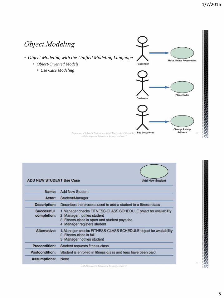
Use Case Modeling
A use case represents the steps in a specific business function or process.
An external entity, called an actor, initiates a use case by requesting the system to
perform a function or process. The UML symbol for a use case is an oval with a label
that describes the action or event.
The actor is shown as a stick figure, with a label that identifies the actor's role.
The line from the actor to the use case is called an association, because it links a
particular actor to a use case.
Department of Industrial Engineering, Sharif University of Technology
MIS (Management Information System), Session #15
9
1/7/2016
5
Object Modeling with the Unified Modeling Language
Object-Oriented Models
Use Case Modeling
Department of Industrial Engineering, Sharif University of Technology
MIS (Management Information System), Session #15
10
Object Modeling with the Unified Modeling Language
Object-Oriented Models
Use Case Modeling
Department of Industrial Engineering, Sharif University of Technology
MIS (Management Information System), Session #15
11

1/7/2016
6
Object Modeling with the Unified
Modeling Language
Object-Oriented Models
Use Case Modeling
Department of Industrial Engineering, Sharif University of Technology
MIS (Management Information System), Session #15
12
Object Modeling with the Unified
Modeling Language
Object-Oriented Models
Use Case Modeling
Department of Industrial Engineering, Sharif University of Technology
MIS (Management Information System), Session #15
13

1/7/2016
7
Object Modeling with the Unified Modeling Language
Object-Oriented Models
Class Diagrams
A class diagram shows the object classes and relationships involved in a use case.
Like a DFD, a class diagram is a logical model, which evolves into a physical model and
finally becomes a functioning information system.
In a class diagram, each class appears as a rectangle, with the class name at the top,
followed by the class's attributes and methods.
Lines show relationships between classes and have labels identifying the action that
relates the two classes.
Department of Industrial Engineering, Sharif University of Technology
MIS (Management Information System), Session #15
14
Object Modeling with the Unified
Modeling Language
Object-Oriented Models
Class Diagram
Department of Industrial Engineering, Sharif University of Technology
MIS (Management Information System), Session #15
15

1/7/2016
8
Object Modeling with the
Unified Modeling Language
Object-Oriented Models
Class Diagram
Department of Industrial Engineering, Sharif University of Technology
MIS (Management Information System), Session #15
16
Object Modeling with the Unified Modeling Language
Object-Oriented Models
Sequence Diagram
A sequence diagram is a dynamic model of a use case, showing the interaction among
classes during a specified time period.
A sequence diagram graphically documents the use case by showing the classes, the
messages, and the timing of the messages.
Sequence diagrams include symbols that represent classes, lifelines, messages, and focuses.
Department of Industrial Engineering, Sharif University of Technology
MIS (Management Information System), Session #15
17

1/7/2016
9
Department of Industrial Engineering, Sharif University of Technology
MIS (Management Information System), Session #15
18
Object Modeling with the Unified
Modeling Language
Object-Oriented Models
Sequence Diagram
Department of Industrial Engineering, Sharif University of Technology
MIS (Management Information System), Session #15
19
Object Modeling with the Unified
Modeling Language
Object-Oriented Models
Sequence Diagram
1/7/2016
10
Object Modeling with the Unified Modeling Language
Object-Oriented Models
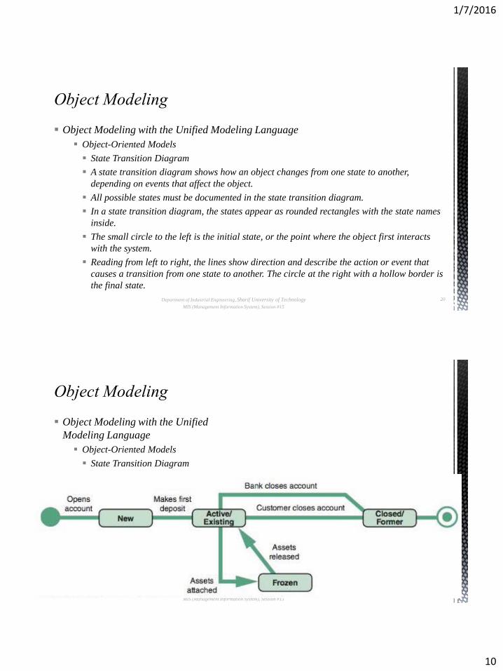
State Transition Diagram
A state transition diagram shows how an object changes from one state to another,
depending on events that affect the object.
All possible states must be documented in the state transition diagram.
In a state transition diagram, the states appear as rounded rectangles with the state names
inside.
The small circle to the left is the initial state, or the point where the object first interacts
with the system.
Reading from left to right, the lines show direction and describe the action or event that
causes a transition from one state to another. The circle at the right with a hollow border is
the final state.
Department of Industrial Engineering, Sharif University of Technology
MIS (Management Information System), Session #15
20
Department of Industrial Engineering, Sharif University of Technology
MIS (Management Information System), Session #15
21
Object Modeling with the Unified
Modeling Language
Object-Oriented Models
State Transition Diagram
1/7/2016
11
Object Modeling with the Unified Modeling Language
Object-Oriented Models
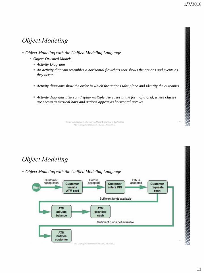
Activity Diagrams
An activity diagram resembles a horizontal flowchart that shows the actions and events as
they occur.
Activity diagrams show the order in which the actions take place and identify the outcomes.
Activity diagrams also can display multiple use cases in the form of a grid, where classes
are shown as vertical bars and actions appear as horizontal arrows
Department of Industrial Engineering, Sharif University of Technology
MIS (Management Information System), Session #15
22
Object Modeling with the Unified Modeling Language
Object-Oriented Models
Activity Diagrams
Department of Industrial Engineering, Sharif University of Technology
MIS (Management Information System), Session #15
23

1/7/2016
12
Object Modeling with the Unified Modeling Language
Object-Oriented Models
Business Process Modeling
In addition to sequence diagrams and activity diagrams, you can use business process
modeling (BPM) to represent the people, events, and interaction in a system.
BPM initially as a requirements modeling tool, works well with object modeling, because
both methods focus on the actors and the way they behave.
In a typical BPM diagram, the outside rectangle is called a pool, and designated swim
lanes show specific actions and events. The swim lanes can interact when certain events
Department of Industrial Engineering, Sharif University of Technology
MIS (Management Information System), Session #15
24