advances in passively driven microfluidics and lab-on-chip
TRANSCRIPT

RSC Advances
REVIEW
Ope
n A
cces
s A
rtic
le. P
ublis
hed
on 2
3 M
arch
202
0. D
ownl
oade
d on
12/
11/2
021
12:4
1:56
AM
. T
his
artic
le is
lice
nsed
und
er a
Cre
ativ
e C
omm
ons
Attr
ibut
ion
3.0
Unp
orte
d L
icen
ce.
View Article OnlineView Journal | View Issue
Advances in pass
aDepartment of Electronics and Comput
Electrical and Electronic Engineering Te
Melaka, Hang Tuah Jaya, 76100 Duria
[email protected]; [email protected], No: 42/12, 7th Street, Vallala
IndiacCentre of Excellence for Advanced Resea
Pahang, Kuantan 26300, MalaysiadDepartment of Biomedical Engineering, Ra
602105, IndiaeFaculty of Electrical and Electronics Engine
26600, MalaysiafFaculty of Electronics and Computer En
Melaka, Hang Tuah Jaya, 76100 Durian TugDepartment of Bioengineering, McGill UnivhFaculty of Industrial Sciences and Technolo
26300, Malaysia
Cite this: RSC Adv., 2020, 10, 11652
Received 10th January 2020Accepted 20th February 2020
DOI: 10.1039/d0ra00263a
rsc.li/rsc-advances
11652 | RSC Adv., 2020, 10, 11652–116
ively driven microfluidics and lab-on-chip devices: a comprehensive literature reviewand patent analysis
Vigneswaran Narayanamurthy, *abc Z. E. Jeroish,de K. S. Bhuvaneshwari,df
Pouriya Bayat,g R. Premkumar,d Fahmi Samsurie and Mashitah M. Yusoffh
The development of passively driven microfluidic labs on chips has been increasing over the years. In the
passive approach, the microfluids are usually driven and operated without any external actuators, fields,
or power sources. Passive microfluidic techniques adopt osmosis, capillary action, surface tension,
pressure, gravity-driven flow, hydrostatic flow, and vacuums to achieve fluid flow. There is a great need
to explore labs on chips that are rapid, compact, portable, and easy to use. The evolution of these
techniques is essential to meet current needs. Researchers have highlighted the vast potential in the field
that needs to be explored to develop rapid passive labs on chips to suit market/researcher demands. A
comprehensive review, along with patent analysis, is presented here, listing the latest advances in passive
microfluidic techniques, along with the related mechanisms and applications.
Introduction
Handling small volumes of uids is very important in high-throughput screening, diagnosis, and research applications.1
Microuidics is one way to handle small volumes of uidsbetween microlitres (10�6) and picolitres (10�12).2–4 Hundreds ofsimultaneous biochemical reactions can be performed ina collection of microarrays arranged on a solid substrate whichacts as laboratories, embedded in which are chips known asbiochips.5,6 There are three main types of biochips: lab on chips(LOCs), DNA chips, and protein chips. LOCs employ a combina-tion of one or more laboratory functions within a single inte-grated chip.7 Some elds utilizing LOCs, such as sub-micrometerand nano-sized channels, DNA labyrinths, single-cell detectionand analysis,8 and nano-sensors, might become feasible,
er Engineering Technology, Faculty of
chnology, Universiti Teknikal Malaysia
n Tunggal, Melaka, Malaysia. E-mail:
my
r Nagar, Chennai, Tamil Nadu 600072,
rch in Fluid Flow, University Malaysia
jalakshmi Engineering College, Chennai
ering, University Malaysia Pahang, Pekan
gineering, Universiti Teknikal Malaysia
nggal, Melaka, Malaysia
ersity, Montreal, QC, Canada H3A 0E9
gy, University Malaysia Pahang, Kuantan
80
allowing new ways to interact with biological species and largemolecules. In addition, a large number of biochemical analysescan be screened at a faster rate in disease diagnosis and thedetection of bioterrorism agents.9 Several reports have beenpublished on the various aspects of these devices, including uidtransport, system properties, sensing techniques,10 and bio-analytical applications. Advantages11,12 include lower fabricationcosts, allowing cost-effective disposable chips and massproduction. Simple tests that could be performed by the bedsideare known as point-of-care (POC) testing.13 The ultimate aim ofthis technique is to obtain results in a concise period at or nearthe location of the patient, so that the treatment plan can beadjusted.14Microuidics can be used for various lab experiments,such as drug testing and discovery,15–23 ltration and separationof particles,24 cell sorting and counting,25–31 cell culture,32–40 point-of-care diagnosis,41,42 3D printing, stoichiometry, and owsynthesis.43,44 Due to their simplicity with high throughput andvery low reagent consumption,45 microuidic chips are vitalcomponents in research, for the delivery of accurate results.46
Microuidic chips are mostly made up of PDMS (poly-dimethylsiloxane). PDMS is commonly used because it isa transparent elastic polymer, permeable to oxygen and carbondioxide.47–51 Additionally, PDMS is now becoming a standardmaterial as it can be easily fabricated for microuidic devices(MFDs), and its high gas solubility, which obeys Henry's law, isa signicant advantage of using PDMS material.52
Microuidic operation techniques
The techniques assisting uid ow in an MFD are generallyclassied as active or passive.53,54 Active microuidics55,56
This journal is © The Royal Society of Chemistry 2020

Review RSC Advances
Ope
n A
cces
s A
rtic
le. P
ublis
hed
on 2
3 M
arch
202
0. D
ownl
oade
d on
12/
11/2
021
12:4
1:56
AM
. T
his
artic
le is
lice
nsed
und
er a
Cre
ativ
e C
omm
ons
Attr
ibut
ion
3.0
Unp
orte
d L
icen
ce.
View Article Online
involves the movement or transport of biological samples andanalysis of those samples through an external power source/eld57–59 or actuators,60 such as peristaltic pumps,61 electro-kinetics,62,63 electro-wetting,64 electro-osmotic pumps,65 electro-statics,66,67 centrifugal and magnetic pumps68 and some otherlarge power sources to power the pumps and actuators.69–71
Thus the complexity of structure and size is increased, whichrequires additional human resources. Hence, the probability ofintegrating active microuidics with LOCs and (POC) applica-tions has dropped off. To counter these drawbacks,72–74 themovement of the test sample is achieved either using uidproperties or passive mechanisms without any external sup-porting power sources. Hence, passive microuidics75 has beenadopted and used to a large extent in modern-day researchprojects to avoid the use of external supporting power devices.This method is simple, easy to manufacture, and does not needany actuators or external power supplies, as it employs basiclaboratory instruments, like micropipettes, and medicaldevices, such as syringe pumps.
Systematic literature search
A systematic literature search has been performed using GoogleScholar with the following keywords: “passive pumping plat-form, passively driven microuidics, pressure head drivenmicrouidics, and ow-driven microuidics” throughout 2000–2018. Fig. 1 presents a pie chart revealing the aggregate numberof articles on passive microuidics published from 2000 to2018. This review article will be useful for researchers who planfurther investigations in this eld.
From Fig. 1, it is evident that pressure-driven, capillary,hydrostatic, surface-tension and vacuum-based methods areleading trends. From the search, articles were selected andsome were hand picked based on their relevancy with anexclusive focus on the passively driven approach and they arepresented according to their timeline. In 2002, David Beebeet al. published a short report on the fabrication of MFDs andthe physics applied to passive valves, mixers, and pumps whichfacilitate uid ow.53 Due to the extensive usage of PDMS inMFDs, Sia et al. reviewed the advantages of using PDMS inminiaturized biological assay devices, such as efficiency and
Fig. 1 Trends in passive microfluidics.
This journal is © The Royal Society of Chemistry 2020
spectral insights into cell biology, where the uidic ow wasobtained by applying a positive or negative pressure at the inletor outlet, respectively.76 Subsequently, Bayraktar et al. reviewedthe available knowledge based on the areas that requiredadditional investigation in pressure-driven and electro-osmoticows in microchannels.77 Later, Fiorini et al. in 2005 reporteda review of different modes of on-chip operations, such as thepumping and valving of uid ow; and the separation anddetection of different chemical species that have been imple-mented in a microuidic format.54 Haeberle et al. reportedplatforms for LOC applications.78 Eventually, a microuidic cellculture was developed, which implied the use of surfacetension, where a differential pressure was generated due to thedifferent volumes in the inlet and outlet port to assist the uidow and which was based on concepts related to physical andmicroenvironments on passive pumping.79 Additionally, Ahnet al. reported a short review in 2010 based on various methodsof passive pumping and their applications to LOC biochemicalanalysis.80
Furthermore, Gervais et al. focused on various techniquesthat have been adapted for passive pumping.74 Later, Su et al.reviewed the latest advances in microuidic platforms for POCtesting in the context of infectious diseases, along with theintegration of multiple functions into a single unit with fullautomation and analysed the challenges involved.81 Subse-quently, Byun et al. summarized recent advances in pumpingtechniques for microuidic cell culture in an effort to supportcurrent and potential users of microuidic-based devices foradvanced in vitro cellular studies.57 The relevant biophysicallaws, along with their experimental details and the designs ofvarious passive separation techniques, were explained by Tri-pathi et al. in 2015.82 These separation techniques advanced thedevelopment of single-cell capture. Eventually, Narayanamurthyet al. focussed on the development of single-cell trapping usinghydrodynamic effects for the purpose of developments in cellseparation and rapid viral detection and explained its benets.83
In this article, we wish to discuss the current proposals,developments, updates, and future of passive microuidic andLOC devices. The different methods adopted in every passivelydriven type of microuidics are briey covered, so that one canobtain a better and clearer knowledge of previous tech-niques.84–86 This also throws light on the advantages, ow ratesand applications of all the techniques. The limitations of eachmethod are also explained.
Patent analysis and current key market players in the eld ofmicrouidics and lab-on-chip devices
A patent analysis was performed with the Google Patentssearch tool, using the keywords, passive AND (driven OR ow)AND (biochips OR microuidics OR LOC), and the analysis isprovided in Fig. 2. The key players in the microuidics marketare Semiconductor Energy Laboratory Co., Ltd. (US), Ther-anos, Inc. (US), Abbott Point Of Care Inc. (US), Micronics, Inc.(US), Danaher (US), Thermo Fisher (US), PerkinElmer (US),Roche (Switzerland), Biomicro Systems, Inc. (US), IncyteGenomics, Inc. (US), Silicon Laboratories, Inc. (US), Tecan
RSC Adv., 2020, 10, 11652–11680 | 11653
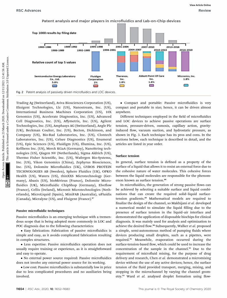
Fig. 2 Patent analysis of passively driven microfluidics and LOC devices.
RSC Advances Review
Ope
n A
cces
s A
rtic
le. P
ublis
hed
on 2
3 M
arch
202
0. D
ownl
oade
d on
12/
11/2
021
12:4
1:56
AM
. T
his
artic
le is
lice
nsed
und
er a
Cre
ativ
e C
omm
ons
Attr
ibut
ion
3.0
Unp
orte
d L
icen
ce.
View Article Online
Trading Ag (Switzerland), Aviva Biosciences Corporation (US),Eksigent Technologies, Llc (US), Nanostream, Inc. (US),International Business Machines Corporation (US), 10XGenomics (US), Accelerate Diagnostics, Inc. (US), AdvancedCell Diagnostics, Inc. (US), Affymetrix, Inc. (US), AgilentTechnologies, Inc. (US), Amphasys AG (Switzerland), Angle Plc(UK), Beckman Coulter, Inc. (US), Becton, Dickinson, andCompany (US), Bio-Rad Laboratories, Inc. (US), ClontechLaboratories, Inc. (US), Celsee Diagnostics (US), Enumeral(US), Epic Sciences (US), Fluidigm (US), Illumina, Inc. (US),Kellbenx Inc. (US), Merck KGaA (Germany), NanoString tech-nologies (US), Qiagen NV (Netherlands), Sigma Aldrich (US),Thermo Fisher Scientic, Inc. (US), Wafergen Bio-Systems,Inc. (US), Yikon Genomics (China), Zephyrus Biosciences,Inc. (US), Dolomite Microuidics (UK), GYROS PROTEINTECHNOLOGIES AB (Sweden), Sphere Fluidics (UK), OPKOHealth (US), Waters (US), thinXXS Microtechnology (Ger-many), Abaxis (US), bioMerieux (France), Dolomite Micro-uidics (UK), Microuidic ChipShop (Germany), Elveow(France), Cellix (Ireland), Micronit Microtechnologies (Neth-erlands), MicroLiquid (Spain), MiniFAB (Australia), uFluidix(Canada), Micralyne (US), and Fluigent (France).87
Passive microuidic techniques
Passive microuidics is an emerging technique with a tremen-dous scope that is being adopted more commonly in LOC andPOC diagnosis due to the following characteristics:
� Easy fabrication: Fabrication of passive microuidics issimple and easy, as it avoids complicated fabrication resultingin complex structures.
� Less expertise: Passive microuidics operation does notusually require training or experience, as it is straightforwardand easy to operate.
� No external power source required: Passive microuidicsdoes not involve any external power source for its working.
� Low cost: Passive microuidics is substantially low in pricedue to less complicated procedures and no auxiliaries beinginvolved.
11654 | RSC Adv., 2020, 10, 11652–11680
� Compact and portable: Passive microuidics is verycompact and portable in size; hence, it can be driven almostanywhere.
Different techniques employed in the eld of microuidicsand LOC devices to achieve passive operations are surfacetension, pressure-driven, osmosis, capillary action, gravity-induced ow, vacuum suction, and hydrostatic pressure, asshown in Fig. 3. Each technique has its pros and cons. In thesections below, each technique is described in detail, and thearticles are listed in year order.
Surface tension
In general, surface tension is dened as a property of thesurface of a liquid that allows it to resist an external force due tothe cohesive nature of water molecules. This cohesive forcesbetween the liquid molecules are responsible for the phenom-enon known as surface tension.88
In microuidics, the generation of strong passive ows canbe achieved by selecting a suitable surface and liquid combi-nations that can create the required solid–liquid surface-tension gradients.89 Mathematical models are required tonalize the design of the channel, so Makhijani et al. developeda numerical model to simulate the liquid lling due to thepresence of surface tension in the liquid–air interface anddemonstrated the application of disposable biochips for clinicaldiagnosis. It was mainly used for analysis and optimization toachieve the desired ow.90 Subsequently, Walker et al. proposeda simple, semi-autonomous method of pumping uids wheredevices producing small droplets, such as a pipettes, wererequired.91 Meanwhile, evaporation occurred during thesurface-tension-based ow, which could be used to increase theconcentration of the sample in the channel.92 Due to therequirement of microuid mixing, for the purpose of drugdelivery and research, Chen et al. demonstrated a micromixingdevice without the use of any active devices; hence, the surfacetension of the uid provided transport, merging, mixing, andstopping in the microchannel by varying the channel geom-etry.93 Ward et al. analysed droplet formation using ow-
This journal is © The Royal Society of Chemistry 2020
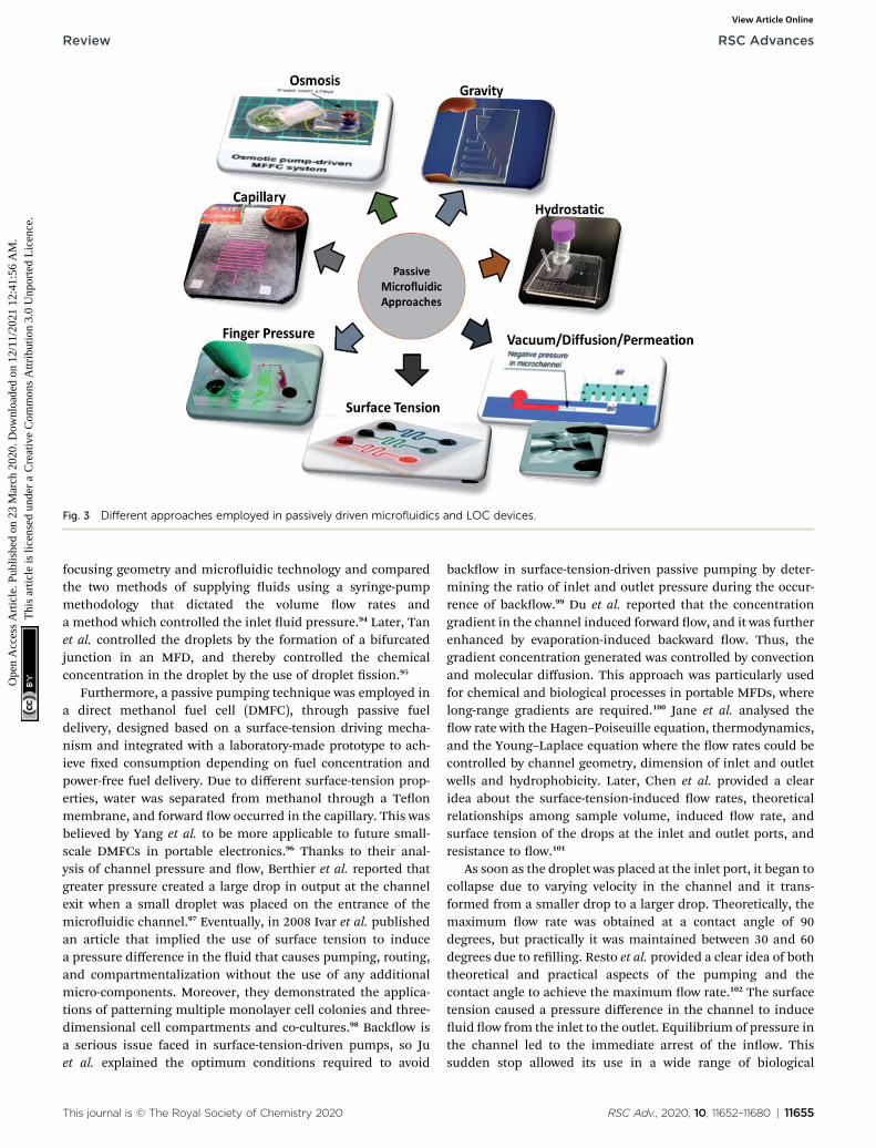
Fig. 3 Different approaches employed in passively driven microfluidics and LOC devices.
Review RSC Advances
Ope
n A
cces
s A
rtic
le. P
ublis
hed
on 2
3 M
arch
202
0. D
ownl
oade
d on
12/
11/2
021
12:4
1:56
AM
. T
his
artic
le is
lice
nsed
und
er a
Cre
ativ
e C
omm
ons
Attr
ibut
ion
3.0
Unp
orte
d L
icen
ce.
View Article Online
focusing geometry and microuidic technology and comparedthe two methods of supplying uids using a syringe-pumpmethodology that dictated the volume ow rates anda method which controlled the inlet uid pressure.94 Later, Tanet al. controlled the droplets by the formation of a bifurcatedjunction in an MFD, and thereby controlled the chemicalconcentration in the droplet by the use of droplet ssion.95
Furthermore, a passive pumping technique was employed ina direct methanol fuel cell (DMFC), through passive fueldelivery, designed based on a surface-tension driving mecha-nism and integrated with a laboratory-made prototype to ach-ieve xed consumption depending on fuel concentration andpower-free fuel delivery. Due to different surface-tension prop-erties, water was separated from methanol through a Teonmembrane, and forward ow occurred in the capillary. This wasbelieved by Yang et al. to be more applicable to future small-scale DMFCs in portable electronics.96 Thanks to their anal-ysis of channel pressure and ow, Berthier et al. reported thatgreater pressure created a large drop in output at the channelexit when a small droplet was placed on the entrance of themicrouidic channel.97 Eventually, in 2008 Ivar et al. publishedan article that implied the use of surface tension to inducea pressure difference in the uid that causes pumping, routing,and compartmentalization without the use of any additionalmicro-components. Moreover, they demonstrated the applica-tions of patterning multiple monolayer cell colonies and three-dimensional cell compartments and co-cultures.98 Backow isa serious issue faced in surface-tension-driven pumps, so Juet al. explained the optimum conditions required to avoid
This journal is © The Royal Society of Chemistry 2020
backow in surface-tension-driven passive pumping by deter-mining the ratio of inlet and outlet pressure during the occur-rence of backow.99 Du et al. reported that the concentrationgradient in the channel induced forward ow, and it was furtherenhanced by evaporation-induced backward ow. Thus, thegradient concentration generated was controlled by convectionand molecular diffusion. This approach was particularly usedfor chemical and biological processes in portable MFDs, wherelong-range gradients are required.100 Jane et al. analysed theow rate with the Hagen–Poiseuille equation, thermodynamics,and the Young–Laplace equation where the ow rates could becontrolled by channel geometry, dimension of inlet and outletwells and hydrophobicity. Later, Chen et al. provided a clearidea about the surface-tension-induced ow rates, theoreticalrelationships among sample volume, induced ow rate, andsurface tension of the drops at the inlet and outlet ports, andresistance to ow.101
As soon as the droplet was placed at the inlet port, it began tocollapse due to varying velocity in the channel and it trans-formed from a smaller drop to a larger drop. Theoretically, themaximum ow rate was obtained at a contact angle of 90degrees, but practically it was maintained between 30 and 60degrees due to relling. Resto et al. provided a clear idea of boththeoretical and practical aspects of the pumping and thecontact angle to achieve the maximum ow rate.102 The surfacetension caused a pressure difference in the channel to induceuid ow from the inlet to the outlet. Equilibrium of pressure inthe channel led to the immediate arrest of the inow. Thissudden stop allowed its use in a wide range of biological
RSC Adv., 2020, 10, 11652–11680 | 11655
RSC Advances Review
Ope
n A
cces
s A
rtic
le. P
ublis
hed
on 2
3 M
arch
202
0. D
ownl
oade
d on
12/
11/2
021
12:4
1:56
AM
. T
his
artic
le is
lice
nsed
und
er a
Cre
ativ
e C
omm
ons
Attr
ibut
ion
3.0
Unp
orte
d L
icen
ce.
View Article Online
applications from reagent delivery to drug-cell studies.103 Janeet al. explained that the surface tension in the uid induced theow through the microchannels due to the change in volumesof uid. Passive microuidics with electrochemical sensorsinside the microchannel was considered for LOC ow injection.Various factors affecting the ow in the microuidic channelwere also discussed. This was the rst report on a passive pumpbased on ow injection analysis (FIA).104 In 2010, Amy et al.integrated particle counting with a passive pumping mecha-nism by placing a 0.5 microliter drop of saline and sample uidon the focussing inlet and the sample inlet, respectively. Thesurface tension in the uid experienced a ow due to the changein volume. These ows to the reservoir traversed a pore thatcaused a change in resistivity, and the pulse was counted. Thus,particle counting was achieved with the help of surface-tensionpumping.105
Puccinelli et al. explained that the pumping process ofa small drop placed at the inlet was due to the surface tension inthe inlet uid. They validated the performance of a complete,reliable, and repeatable cell-based biological assay. Therobustness of each technique was also discussed.106 Chung et al.described the involvement of surface tension, as well as evap-oration, leading to the generation of passive pumping ina forward and backward direction with a concentration gradienta few centimeters long in the channel. Recent developments inmicrouidic gradient generators were also described in theirwork.107 Besides research, Lin et al. demonstrated the uses andapplications of microuidics in the elds of food, environment,and physiological health monitoring.108 Berthier et al. suggestedthat the surface tension of the uid enabled a short-termlaminar ow patterning in multiple uids when the samplewas loaded in any sequence. Numerical simulations and prac-tical experiments were conducted to study the laminar behav-iour. This method was well suited to a cell-based assay andreduced the complexities of laminar ow patterning (LPF).109 In2012, Resto et al. developed inertia-enhanced passive pumpingthat reduced uid exchange and inertia-activated ow, whichinitiates the ow in an empty channel where uid ow took
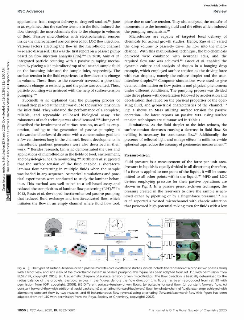
Fig. 4 (i) The types of surface-tension-driven passivemicrofluidics in diffewith a front view and side view of the microfluidic system in passive pumELSEVIER, copyright: 2018). (ii) A schematic diagram of surface tensionradius balance of the droplets; the bold arrows in the figures denote tpermission from IOP, copyright: 2008). (iii) Different surface-tension-dconstant forward-flow with additional liquid packets, (d) alternating (forwalternating constant flow by two nozzles, and (f) instantaneous flow readapted from ref. 110 with permission from the Royal Society of Chemis
11656 | RSC Adv., 2020, 10, 11652–11680
place due to surface tension. They also analysed the transfer ofmomentum to the incoming uid and the effect which inducedthe pumping mechanism.110
Microdevices are capable of targeted focal delivery ofchemicals for axonal growth studies. Hence, Kuo et al. variedthe drop volume to passively drive the ow into the micro-channel. With this manipulation technique, the bio-chemicalsdelivered were combined with neuronal cells, and therequired ow rate was achieved.111 Groot et al. enabled thedynamic culture and analysis of tissues in a hanging dropexample, which employed surface tension as the driving forcewith two droplets, namely the culture droplet and the user-interface droplet.112 Computer simulations were used to givedetailed information on ow patterns and physical phenomenaunder different conditions. The pumping process was dividedinto three planes with deceleration followed by acceleration anddeceleration that relied on the physical properties of the oper-ating uid, and geometrical characteristics of the channel.113
Fig. 4 shows an MFD utilizing surface tension for passiveoperation. The latest reports on passive MFD using surfacetension techniques are summarised in Table 1.
Limitations. As the uid droplet at the inlet reduces, thesurface tension decreases causing a decrease in uid ow. Sorelling is necessary for continuous ow.57 Additionally, thepresence of reected light and mirage effects in millimetre-widespherical caps reduce the accuracy of goniometer measurement.97
Pressure-driven
Fluid pressure is a measurement of the force per unit area.Pressure in liquids is equally divided in all directions; therefore,if a force is applied to one point of the liquid, it will be trans-mitted to all other points within the liquid.114 MFD and LOCdevices employing pressure for their passive operations areshown in Fig. 5. In a passive pressure-driven technique, thepressure created in the reservoirs to drive the sample is ach-ieved either by pipetting or by a nger-force pressure.115 Liuet al. reported a twisted microchannel with chaotic advectionthat possessed high potential mixing even for uids with a low
rent studies, which include the recession of a drop in two phases alongping (this figure has been adapted from ref. 113 with permission fromdriven microfluidics. The flow direction is basically determined by thehe flow direction (this figure has been reproduced from ref. 99 withriven flows: (a) pulsatile forward flow, (b) constant forward flow, (c)ard/backward) flow, (e) whole-channel fluidic exchange achieved withversal using alternating (forward/backward) flow (this figure has beentry, copyright: 2012).
This journal is © The Royal Society of Chemistry 2020

Tab
le1
Rece
ntsu
rfac
e-tension-d
rive
npassive
pumpingtech
niquesin
microfluidics
S.no
Analytes
used
Materials
used
Aux
iliaries
involved
Flow
rate
Adv
antages
Disad
vantages
App
lication
sRef.n
o
1Airan
dwater
PDMS,
SU-8
photoresist
10mlmin
�1
New
tonianan
dnon
-New
tonianuids
were
han
dled
Acompu
tation
almod
elwas
stud
iedalon
eDispo
sablemicrouidic
biochips
90
2Water
PDMS
Pipe
tteor
syringe
1.25
mls�
1Easyinterfacing
Evapo
ration
occu
rsSm
alllabs
andhigh-
throug
hpu
tassaying
system
s
91
3Fluo
rescen
tsp
heres
inDIwater
PDMS
Pipe
tte
Con
stan
tow
rate
Evapo
ration
isaslow
process
Biologicalor
chem
ical
application
92
4Red
andgreen
uo
rescen
tsp
heres
inDIwater
PDMS
Pipe
tte
Simplean
dpo
rtab
leThemixingprocess
beginson
lya
erthe
mergingof
liqu
ids
Micro
totalan
alysis
system
93
5Pu
reoleicacid
and
water
PDMSmou
ldswith
glass
Syringe
pump
Red
uced
useof
reag
ent
Droplet
symmetricis
correctedon
lywiththe
asym
metricow
High-throug
hpu
tscreen
ing
95
6Pu
remethan
olPD
MS
2mlmin
�1
Tou
ghtran
sportation
ofmethan
olin
afewhou
rsSm
all-s
cale
DMFC
sfor
portab
leelectron
ics
96
7PD
MS,
SU-8
photoresist
Micropipe
tte
Practically
analyzed
and
longlasting
Increase
intheou
tput
pressu
rede
creasesow
Cellstud
ies
97
8Cellculture
med
ium
withprotein
PDMS
Pipe
tte
34.6
nls�
1to
16.6
mls�
1Highly
paralle
larrays
with3D
cellcu
ltures
are
employed
Not
applicab
leto
high-
density
valvearrays
Diagn
ostics
anddrug
developm
ent
98
9Mixture
ofDIwater
&uo
rescen
tpa
rticles
PDMS
Pipe
tte
Back
owdu
eto
ow
rotation
ofou
tlet
liqu
id99
10DIwater
and
methan
olPD
MS
Pipe
tte
85nls�
1to
196
nls�
1Geo
metricalprop
erties
canaff
ecttheow
rate
LOCde
vices
101
11DPB
SwithFITC
dextran(culture
med
ium)
PDMS
Pipe
tte
Easilyad
aptablewith
highthroug
hpu
tGradien
tgenerationis
affectedby
uid
viscosity
Biologicalan
ddrug
discoveryap
plications
100
12PD
MS
Automated
uid
delivery
system
4mlmin
�1
Nosu
bstratebo
ndingis
requ
ired
Flow
ratesarelimited
byde
vice
dimen
sion
Cellcu
lturean
dbiolog
ical
applications
102
13Fluo
rescen
tbe
ads
PDMS
Automated
uid
delivery
system
4mlmin
�1
Nosu
bstratebo
ndingis
requ
ired
Con
trol
ofow
directionis
difficu
ltBiologicalap
plications,
drug
-cellstud
ies
103
14Blood
orplasma
mixed
withglycerol
PDMS
Pipe
tte
Minim
alreagen
tconsu
mption,a
nd
waste
generation
Drastic
decrease
inow
rate
over
time
Immun
oassaysan
dLO
C10
4
15Sa
line
PDMS
Pipe
tte
2.35
mlmin
�1
Particle
coun
tingis
donewithin
thesystem
External
power
source
isrequ
ired
forcoun
ting
POCor
diag
nosticMFD
105
16Normal
urine,
mam
maryglan
dep
ithelialcells
PDMS
Pipe
tteor
automated
liqu
idhan
dlingsystem
Red
uced
num
berof
cells
andreag
ents
are
requ
ired
Reagents
withdifferen
tviscosityor
surface
tension
shou
ldbe
optimized
Screen
ingin
cellcu
lture
andbiolog
ical
cell-
basedassay
106
17Neu
trop
hils,
tumor
cells
,stem
cell,
neu
rons,
and
bacterialcells
Glass
subs
tratewith
PDMSmou
ldPipe
tte
Man
ipulationof
uid
ow
,andreal-tim
emon
itoringof
thecells
Com
plicated
microfabrication
process
Chem
otaxis,s
tem
cell
differen
tiation,a
nd
endo
thelialcell
migration
107
This journal is © The Royal Society of Chemistry 2020 RSC Adv., 2020, 10, 11652–11680 | 11657
Review RSC Advances
Ope
n A
cces
s A
rtic
le. P
ublis
hed
on 2
3 M
arch
202
0. D
ownl
oade
d on
12/
11/2
021
12:4
1:56
AM
. T
his
artic
le is
lice
nsed
und
er a
Cre
ativ
e C
omm
ons
Attr
ibut
ion
3.0
Unp
orte
d L
icen
ce.
View Article Online

Tab
le1
(Contd.)
S.no
Analytes
used
Materials
used
Aux
iliaries
involved
Flow
rate
Adv
antages
Disad
vantages
App
lication
sRef.n
o
18PD
MS
Pipe
tte
Lowreag
ent
consu
mptionan
deasy
tofabricate
Loweffi
cien
cyFo
odan
dremote
militaryop
erations,
hom
ehealthcare
108
19PB
Swithredan
dgreenfood
colorant
PDMS
Pipe
tte
Cellpo
pulation
canbe
patterned
Mixingof
sample
Wou
nd-healingassay
109
20Green
,yellowan
dbluedy
esPD
MS
4mlmin
�1
Highow
ratesare
observed
Designingof
small
chan
nel
istoug
hCell-b
ased
assays
110
21Axon,D
Iwater
PDMS,
parylene
Pipe
tte
�0.63mls�
1Flexible
andus
erconvenient
Thesamech
emical
concentration
Axonal
guidan
cestud
ies
111
22Bon
emarrow
stromal
cells
Polymer
sheets
Micropipe
tte
Sepa
ration
ofcells
iscompa
ratively
good
Increasedsp
ace
requ
irem
ent
Microscale
metab
olom
ics
112
23Water
Micropu
mps
4mlmin
�1
Straightforw
ard
implem
entation
ofch
annels
Rad
iiof
thedrop
letv
ary
Drugde
livery
andcell
biolog
y11
3
11658 | RSC Adv., 2020, 10, 11652–11680
RSC Advances Review
Ope
n A
cces
s A
rtic
le. P
ublis
hed
on 2
3 M
arch
202
0. D
ownl
oade
d on
12/
11/2
021
12:4
1:56
AM
. T
his
artic
le is
lice
nsed
und
er a
Cre
ativ
e C
omm
ons
Attr
ibut
ion
3.0
Unp
orte
d L
icen
ce.
View Article Online
Reynolds number.116 Ahn et al. suggested the uid controltechnique and veried that the low-pressure drop in the uidtended to maintain the ow without any complicated pumps.117
Also, Jeon et al. described the design and fabrication of passivevalves and pumps, which used the pressure-driven mechanisminstead of electro-osmotic pumps. The fabrication includedaligning, stacking, and bonding of a patterned membrane.118
Rush et al. established a 2D serpentine channel with the ow oflow-Reynolds-number Brownian solute particles.119 Later,Moorthy et al. developed an on-chip porous lter that separatesminimal volumes of biological uids in real-time applicationsand analysis.120 Also, Hu et al. investigated the relationshipbetween the pressure drop in the rough channel and smoothchannels and also the pressure drop due to a change in height.It was found that in a rough channel the pressure dropincreased and when the channel height increased the pressuredrop decreased.121
Chen et al. explained that a wavy-wall section incorporatedwithin the microchannel developed a centimetre-long highconcentration gradient by increasing the interfacial leads.122
Jiang et al. explained the push or pull in the sample uid due toa negative or positive pressure that a syringe pump wouldcreate.123 Hattori et al. conrmed that uid ow commencedonly when the pressure was applied to the uid by usinga syringe pump or micropipette through an air vent lter.124 Inaddition, when a nger-powered pressure of about 3–4 kPa wasapplied at the inlet, sample movement occurred.114 In theirinvestigations, Davey et al. recommended a system where theinlet and the outlet were a hydrophobic and a hydrophilicneedle, respectively, and the channel was made of a hydrophilicregion where the uid from the inlet traversed the channel andreached the outlet.125 Tice et al. reported an electrostaticmicrovalve with passive components embedded in them, whichwas used to regulate the pressure in hydraulic control lines andactuate pressure-driven components.126
Finger-power integrated pumping systems had been utilizedto eradicate the limitations produced by the use of externalpumps. Pressure generated inside the pressure chamber playeda vital role in determining the efficiency of nger-poweredpumps.127 Thus the requirement for pre-evacuation of PDMSdevices in a vacuum chamber was eliminated. Thereby, thedesign of a simple POC pumping method using a single-layerstructure where the dead-end microuidic channel was partlysurrounded by an embedded microchamber, with a thin PDMSwall separating the dead-end channel and the embeddedmicrochamber, was reported by Xu et al.128 But the workingliquid created a reduced pressure in the analytical channel andinduced sequential sample ow into the microuidic circuits.Kokalj et al. reported simplied activation by ngertip pressurewith no external power or control for a wide range of applica-tions in POC diagnostic settings.129 Jeong et al. developed an on-chip microow control technology with the ability to mimic invivo conditions at an in vitro microscale for long-term tissueculture with a continuous ow rate. The passive ow was initi-ated using a siphon effect, and a yarn ow resistor to regulatethe ow rate in the microchannel.130 Thanks to implantabledrug delivery systems, a micropump for controlled, automated
This journal is © The Royal Society of Chemistry 2020
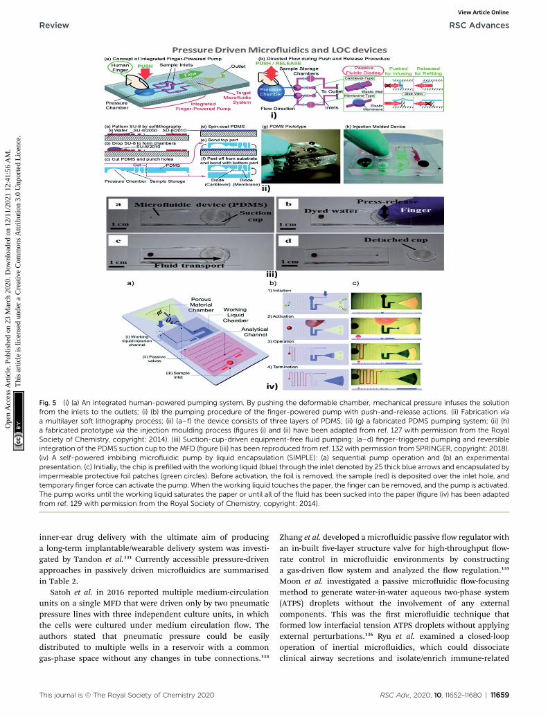
Fig. 5 (i) (a) An integrated human-powered pumping system. By pushing the deformable chamber, mechanical pressure infuses the solutionfrom the inlets to the outlets; (i) (b) the pumping procedure of the finger-powered pump with push-and-release actions. (ii) Fabrication viaa multilayer soft lithography process; (ii) (a–f) the device consists of three layers of PDMS; (ii) (g) a fabricated PDMS pumping system; (ii) (h)a fabricated prototype via the injection moulding process (figures (i) and (ii) have been adapted from ref. 127 with permission from the RoyalSociety of Chemistry, copyright: 2014). (iii) Suction-cup-driven equipment-free fluid pumping: (a–d) finger-triggered pumping and reversibleintegration of the PDMS suction cup to the MFD (figure (iii) has been reproduced from ref. 132 with permission from SPRINGER, copyright: 2018).(iv) A self-powered imbibing microfluidic pump by liquid encapsulation (SIMPLE): (a) sequential pump operation and (b) an experimentalpresentation. (c) Initially, the chip is prefilled with the working liquid (blue) through the inlet denoted by 25 thick blue arrows and encapsulated byimpermeable protective foil patches (green circles). Before activation, the foil is removed, the sample (red) is deposited over the inlet hole, andtemporary finger force can activate the pump. When the working liquid touches the paper, the finger can be removed, and the pump is activated.The pump works until the working liquid saturates the paper or until all of the fluid has been sucked into the paper (figure (iv) has been adaptedfrom ref. 129 with permission from the Royal Society of Chemistry, copyright: 2014).
Review RSC Advances
Ope
n A
cces
s A
rtic
le. P
ublis
hed
on 2
3 M
arch
202
0. D
ownl
oade
d on
12/
11/2
021
12:4
1:56
AM
. T
his
artic
le is
lice
nsed
und
er a
Cre
ativ
e C
omm
ons
Attr
ibut
ion
3.0
Unp
orte
d L
icen
ce.
View Article Online
inner-ear drug delivery with the ultimate aim of producinga long-term implantable/wearable delivery system was investi-gated by Tandon et al.131 Currently accessible pressure-drivenapproaches in passively driven microuidics are summarisedin Table 2.
Satoh et al. in 2016 reported multiple medium-circulationunits on a single MFD that were driven only by two pneumaticpressure lines with three independent culture units, in whichthe cells were cultured under medium circulation ow. Theauthors stated that pneumatic pressure could be easilydistributed to multiple wells in a reservoir with a commongas-phase space without any changes in tube connections.134
This journal is © The Royal Society of Chemistry 2020
Zhang et al. developed amicrouidic passive ow regulator withan in-built ve-layer structure valve for high-throughput ow-rate control in microuidic environments by constructinga gas-driven ow system and analyzed the ow regulation.135
Moon et al. investigated a passive microuidic ow-focusingmethod to generate water-in-water aqueous two-phase system(ATPS) droplets without the involvement of any externalcomponents. This was the rst microuidic technique thatformed low interfacial tension ATPS droplets without applyingexternal perturbations.136 Ryu et al. examined a closed-loopoperation of inertial microuidics, which could dissociateclinical airway secretions and isolate/enrich immune-related
RSC Adv., 2020, 10, 11652–11680 | 11659

Tab
le2
Rece
ntpressure-d
rive
nap
proac
hesin
passive
lydrive
nmicrofluidics
S.no
Analytes
used
Materials
used
Aux
iliaries
involved
Flow
rate
Adv
antages
Disad
vantages
App
lication
sRef.n
o
1So
dium
hyd
roxide
andethyl
alcohol
PDMSmem
bran
eSyringe
pump
Minim
umch
ancesof
clog
ging,
fouling,
and
loss
ofsample
Increasedin
thecomplexity
ofow
Bioch
emistry
analysis,d
rug
delivery
116
2PD
MS
1mlmin
�1
Flow
rate
canbe
tailored
basedon
chan
nel
heigh
t
Lowow
rate
Bioch
emical
analysis
system
s11
7
3Plasma
PDMS
Usedwheretheelectro-
osmotic
pumpingisnot
feasible
Miniaturization
ofSi
valves
was
difficu
ltDispo
sable
diag
nostican
ddrug
screen
ing
applications
118
4Incompressible
New
tonianuid
Limited
bytheirtotal
length
119
5Fluo
rescen
t-labe
led
bead
s,rabb
itbloo
dPre-po
lymer,g
lass
Pipe
tte
10an
d20
mlmin
�1
Eliminates
theneedfor
centrifug
ingprinciple
Drugde
livery,c
ell
culture
120
6Water
Pressu
redrop
inthe
microch
annel
inhigh
LOC
121
7Incompressible
New
tonianliqu
ids
Bothactive
andpa
ssive
mixingarerequ
ired
Drugde
livery,D
NA
hyb
ridization
122
8Microbe
ads,bloo
dPD
MS
Syringe
pump
Inexpe
nsive,fastan
dsensitive
foruidow
Diffi
cultto
integratewith
POC
Immun
oassay
123
9Water
withred-
coloured
dye
Glass
slide
3–4kP
apressu
realon
eis
requ
ired
External
pressu
reis
requ
ired
POCdiag
nostics
114
10Viscousliqu
idPD
MS
Syringe
pump
500mlmin
�1
Highly
stab
leDetection
ofair-
bornecontaminan
ts12
5
11Culture
med
iaPD
MS
Micropipe
tte
Efficien
t,us
er-frien
dly
Drugdiscovery
124
12Drugof
interest
Polyam
ide
Drugload
ingpu
mp
40mlmin
�1
Req
uiresnoad
dition
alvalves
toassist
theow
Con
stan
tdo
sage
Cochlear
drug
delivery
system
133
13Rab
bitbloo
dPD
MS,
parylene
Microneedle
Simplein
vivo
bloo
dsamplingprocess
Needs
tobe
operated
inpn
eumatic
platform
sBiosensorch
ip12
6
14Green
-dyedwater
3-La
yeredPD
MS
Pipe
tte
3.75
times
greaterthan
water
ow
Transp
ortation
ofsingu
laruids
ispo
ssible
Pressu
revaries
dueto
the
useof
differen
tngers
Pointof
care
and
disp
osab
lebiom
edical
equipm
ent
127
15Deion
ised
water
PDMS
Syringe
0.08
9to
4nls�
1Syringe
supp
lies
pressu
resource
todrive
POCpu
mping
system
128
16Bluean
dreddy
edwater
PDMS
Syringe
orpipe
tte
0.07
,0.12an
d0.17
mls�
1Com
bined
withthe
hyd
roph
obic
polymer
system
tostay
stab
le
Speedde
creaseswithlling
thech
annel
Pointof
care
diag
nosis
129
17Endo
thelialcell
(hum
an)
PDMS
Pipe
tte
10–100
mlh�1
Physiologicallevels
ofow
canbe
regu
lated
Dep
ende
ncy
onheigh
tCell-b
ased
applications
130
18La
yers
ofPE
Iforthe
rigidstructure
Electronic
dose
control
13–18mlmin
�1
Increasedeffi
cien
cywithin
thesystem
Red
uction
insystem
pressu
reis
toug
hHair-cell
regeneration
therap
y
131
19Umbilicalvein
endo
thelialcells
PDMS
Pipe
tte
950mlmin
�1
Easydistribu
tion
ofpressu
reCellcu
lturein
drug
discoveryan
dpo
int
ofcare
134
11660 | RSC Adv., 2020, 10, 11652–11680 This journal is © The Royal Society of Chemistry 2020
RSC Advances Review
Ope
n A
cces
s A
rtic
le. P
ublis
hed
on 2
3 M
arch
202
0. D
ownl
oade
d on
12/
11/2
021
12:4
1:56
AM
. T
his
artic
le is
lice
nsed
und
er a
Cre
ativ
e C
omm
ons
Attr
ibut
ion
3.0
Unp
orte
d L
icen
ce.
View Article Online
Tab
le2
(Contd.)
S.no
Analytes
used
Materials
used
Auxiliariesinvolved
Flow
rate
Adv
antages
Disad
vantages
App
lication
sRef.n
o
20PD
MSwithoxygen
plasmatreatm
ent
1.42
mlmin
�1
Con
stan
tow
rate
unde
rthesinus
oida
llyvaryingsign
alis
seen
POCdiag
nostic
devices
135
21Micropa
rticle
stock
solution
withDEX
CAD
designfor
chan
nels
Pipe
tteor
syringe
1.55
mlmin
�1
Mon
o-disp
erseddrop
let
form
ationis
achieved
Cellan
alysis,c
ell-
basedassays
136
22Sterilesp
utum
PDMS
Micropipe
tte
4mlmin
�1
Highrecovery
rate
ofleuk
ocytes
Pulm
onarydiseases
detection
137
23Ph
osph
atebu
ffer
PDMS
Syringe
pump
80mlmin
�1
Rap
iduidmixing
Enzyme-ba
sedassay
138
24Dyeddeion
ized
water
andmineral
oil
PDMS
Pressingan
dreleasingcu
pIncreasingow
rate
Simplean
deff
ective.
Fabricationof
cupis
easy
Diameter
ofthecu
pstop
stheow
Resou
rce-limited
applications
132
25Glyceroldilutedin
water
PVCan
dPM
MA
Fingeractivation
0.5–15
0mlm
in�1
Drugde
livery
applications
139
26Ethyl
alcohol,
aceton
ePD
MS
Te
ontube
toreleaseair
30.56–33
.98
mlmin
�1
Increasedexibilityan
dinde
pende
nt
Immun
oassays
140
This journal is © The Royal Society of Chemistry 2020
Review RSC Advances
Ope
n A
cces
s A
rtic
le. P
ublis
hed
on 2
3 M
arch
202
0. D
ownl
oade
d on
12/
11/2
021
12:4
1:56
AM
. T
his
artic
le is
lice
nsed
und
er a
Cre
ativ
e C
omm
ons
Attr
ibut
ion
3.0
Unp
orte
d L
icen
ce.
View Article Online
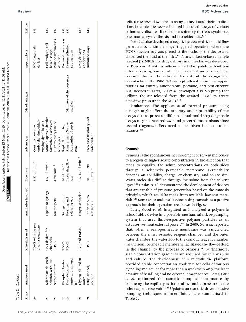
cells for in vitro downstream assays. They found their applica-tions in clinical in vitro cell-based biological assays of variouspulmonary diseases like acute respiratory distress syndrome,pneumonia, cystic brosis and bronchiectasis.137
Lee et al. also developed a negative pressure-driven uid owgenerated by a simple nger-triggered operation where thePDMS suction cup was placed at the outlet of the device anddispensed the uid at the inlet.132 A new infusion-based simplemethod (ISIMPLE) for drug delivery into the skin was developedby Dosso et al. with a self-contained skin patch without anyexternal driving source, where the expelled air increased thepressure due to the extreme exibility of the design andmanufacture. The ISIMPLE concept offered enormous oppor-tunities for entirely autonomous, portable, and cost-effectiveLOC devices.139 Later, Liu et al. developed a PDMS pump thatutilized the air released from the aerated PDMS to createa positive pressure in the MFD.140
Limitations. The application of external pressure usinga nger might affect the accuracy and repeatability of theassays due to pressure difference, and multi-step diagnosticassays may not succeed via hand-powered mechanisms sinceseveral reagents/buffers need to be driven in a controlledmanner.141
Osmosis
Osmosis is the spontaneous net movement of solvent moleculesto a region of higher solute concentration in the direction thattends to equalize the solute concentrations on both sidesthrough a selectively permeable membrane. Permeabilitydepends on solubility, charge, or chemistry, and solute size.Water molecules diffuse through the solute from the solventlayer.142 Bruhn et al. demonstrated the development of devicesthat are capable of pressure generation based on the osmosisprinciple, which could be made from available low-cost mate-rials.143 Some MFD and LOC devices using osmosis as a passiveapproach for their operation are shown in Fig. 6.
Later, Good et al. integrated and analyzed a polymericmicrouidic device in a portable mechanical micro-pumpingsystem that used uid-responsive polymer particles as anactuator, without external power.144 In 2009, Xu et al. reportedthat, when a semi-permeable membrane was sandwichedbetween the inner osmotic reagent chamber and the outerwater chamber, the water ow to the osmotic reagent chambervia the semi-permeable membrane facilitated the ow of uidin the channel by the process of osmosis.145 Furthermore,stable concentration gradients are required for cell analysisand culture. The development of a microuidic platformprovided stable concentration gradients for cells of varioussignaling molecules for more than a week with only the leastamount of handling and no external power source. Later, Parket al. optimized the osmotic pumping performance bybalancing the capillary action and hydraulic pressure in theinlet reagent reservoirs.146 Updates on osmotic-driven passivepumping techniques in microuidics are summarised inTable 3.
RSC Adv., 2020, 10, 11652–11680 | 11661

Fig. 6 (i) Osmotic pump schematic diagram (this figure has been adapted from ref. 147 with permission from the Royal Society of Chemistry,copyright: 2009). (ii) Osmotic pump operation (this figure has been reproduced from ref. 57 with permission fromWiley, copyright: 2014). (iii) Anoperational diagram of the system, including the pump unit and the Poiseuille flow with constant wall shear stress (this figure has been adaptedfrom ref. 148 with permission from IOS Press, copyright: 2010). (iv) Experimental setup with four components, namely concentration gradient,pipette tips, osmotic pumps and coiled tube (this figure has been reproduced from ref. 146 with permission from Alpha Med Press, copyright:2009). (v) A microfluidic fuel cell (MFFC) system using an osmotic pump (this figure has been adapted from ref. 149 with permission from IOP,copyright: 2018).
RSC Advances Review
Ope
n A
cces
s A
rtic
le. P
ublis
hed
on 2
3 M
arch
202
0. D
ownl
oade
d on
12/
11/2
021
12:4
1:56
AM
. T
his
artic
le is
lice
nsed
und
er a
Cre
ativ
e C
omm
ons
Attr
ibut
ion
3.0
Unp
orte
d L
icen
ce.
View Article Online
Limitations. An osmotically driven mechanism needsa complex setup compared to surface-tension, capillary, andgravity-driven setups.57 In osmotic drug delivery systems rell-ing the reservoirs was mostly impossible or complicated withthe constant drug delivery rate.144 The development of anadditional reservoir for the solvents increased the devicecomplexity for operation in any environment.150
Capillary
Capillary action is dened as the movement of a uid within thespaces of a porous material due to the intermolecular forcesbetween the liquid and the surrounding solid surfaces thatenables the liquid to ow in narrow spaces without the assis-tance of, or even in opposition to, external forces like gravity.87
Juncker et al. reported a capillary pump assisted capillaryow microuidic system, where the ow was activated from theopen and closed channels of the device.151 MFD and LOCdevices incorporating the capillary technique are shown in
11662 | RSC Adv., 2020, 10, 11652–11680
Fig. 7. Simultaneously, a microuidic capillary system waspresented for the continuous transport of uid using capillaryforce, when the uid was placed in the service port.151 Mixing ofuids is necessary for drug delivery and research. So, Hosokawaet al. reported an MFD which used capillary force for pump-ing.152 To avoid clogging by uids, Kim et al. presented a capil-lary passive retarding microvalve at the junction of themicrouidic channel where the propagation occurred only aerthe merging of two uids.153 An exact discussion of interfacemotion driven by capillary action in a microchannel was re-ported by Ichikawa et al. where a dimensionless variable of thedriving force was used to predict the interface motion.154 Inorder to maintain and control the ow properties of capillarysystems (CSs), Zimmermann et al. developed a design forcapillary pumps. These capillary pumps were designed to havea small ow resistance and were preceded by a constrictedmicrochannel, which caused ow resistance.155 Subsequently,Suk et al. developed a technique to control the autonomous
This journal is © The Royal Society of Chemistry 2020

Tab
le3
Rece
ntosm
otic-
drive
npassive
pumpingtech
niquesin
microfluidics
S.no
Analytes
used
Materials
used
Aux
iliaries
involved
Flow
rate
Adv
antages
Disad
vantages
App
lication
sRef.n
o
1Sieved
particles
PDMSan
dnatural
rubb
erDropp
er17
mlmin
�1
Can
beplaced
directly
onamicrode
vice
Reactivationof
pump
requ
ires
water
Finds
the
applicationin
portab
lede
vices
144
2PD
MSch
ambe
rSyringe
0.33
mlmin
�1
Lowow
rate
isus
edfor
constan
trefreshingof
culturemed
ium
Regular
refreshingof
osmotic
reag
ent
Microuidicow
injectionsystem
145
3Choleratoxin
subu
nitB
PDMScu
bic
cham
bers
Micro-pipette
0.15
mlh�1
Provides
the
concentrationgrad
ient
formorethan
aweek
Lowow
rate
Basic
and
tran
slational
research
areassu
chas
stem
cell
differen
tiation
research
andlong-
term
cellcu
lture
146
This journal is © The Royal Society of Chemistry 2020
Review RSC Advances
Ope
n A
cces
s A
rtic
le. P
ublis
hed
on 2
3 M
arch
202
0. D
ownl
oade
d on
12/
11/2
021
12:4
1:56
AM
. T
his
artic
le is
lice
nsed
und
er a
Cre
ativ
e C
omm
ons
Attr
ibut
ion
3.0
Unp
orte
d L
icen
ce.
View Article Online
capillary ow with a passive method where the ow could beretarded with appropriate hydrophobic patterns in hydrophilicchannel surfaces. Themicrouidic system was designed in sucha way that it contained two planar parallel surfaces, separatedby spacers.156
Flow rates may vary in different substrates, so Zhu et al. re-ported a study of capillary ow rate in several substances,including glass, polycarbonate (PC) and polydimethylsiloxane(PDMS) to measure the contact angles and to examine thelongevity of capillary ow in PDMS and PC chips to give betterclarity in measuring the ow rates.157 Lynn et al. realizeda pressure difference arising from the small curved meniscus atthe bottom of the outlet reservoir that drove the uid witha constant uid ow for more than an hour.158 Later, Gervaiset al. described the uid ow from high capillary pressure to lowcapillary pressure and increased the channel width at each levelto reduce the friction, thereby leading to a high ow rate.159
Mukhopadhyay et al. proposed a microchannel bend in poly-methylmethacrylate (PMMA) of different widths. The effects ofchannel aspect ratio and different separation angles werestudied for uid ow.160 Eventually, Alphonsus et al. explainedin a short review on microuidic immunoassay that the capil-lary pressure in the channel pushed the sample, causing theuid to ow within the device.161 Kim et al. realized that thesurfactant-added PDMS could be used to increase the hydro-phobicity of PDMS to increase the lling rate of blood bycapillary action.162 Souza et al. fabricated a toner-based micro-uidic device in which the uid owed towards the outlet assoon as the serum was placed in the sample inlet.163 Later,Horiuchi et al. also developed an immunoassay chip whichconsisted of vertically integrated capillary tubes to createnegative pressure and pump the uid towards it.164 Once theuid had been placed in the inlet well, Kim et al. veried theow timing control and direction of multiple solutions in thechannel.165
Kistrup et al. reported aspects of using rapid prototypinginstead of pilot (mass) production. They included the fabrica-tion of the microuidic system that employed injectionmoulding and ultrasonic welding in which the uid ow wasassisted by the capillary pressure at the interface nozzle.166
Berthier et al. proposed the onset of the suspended capillaryows (SCF) and the viscous friction at the walls using the forcebalance between the capillary forces that drove the ow.167
Plasma separation is possible in passive pumping microuidictechnology. Madadi et al. demonstrated a self-driven bloodplasma separation microuidic chip, which was capable ofextracting more than 0.1 ml of plasma from a single droplet ofundiluted fresh human blood (5 ml) with high purity without anyexternal pumps.168 Nie et al. reported a exible microuidicdevice that lled the channel through capillary force to providecontinuous uid pumping through an evaporation micropump.The hexagonal arrangement at the pore array drove the uidow and automatically absorbed liquid through a lter paperinterface.169 Mukhopadhyay et al. described a leakage-freePMMA fabricated MFD with microchannel bends with theeffect of surface wettability on surface-driven capillary ow.This type of microuidic system was utilized in blood cell
RSC Adv., 2020, 10, 11652–11680 | 11663

Fig. 7 (i) Schematic diagrams of a microfluidic device for self-propelled continuous-flow PCR: (a) concept diagram; (b) a cross-sectional view ofthe microfluidic device. (c) A photograph of the fabricated microfluidic device (this figure has been reproduced from ref. 182 with permissionfrom Elsevier, copyright: 2015). (ii) A yarn flow resistance (YFR)-regulated microflow control system: (a) a schematic diagram showing the siphoneffects in the yarn-capillary-resistance-driven micropump system; (b) a schematic diagram of the water-head-difference-driven siphon effectcontrolled by the YFR; (c) a photographic image of a yarn capillary regulator; (d) the microfluidic device prepared with a YFR (this figure has beenadapted from ref. 130 with permission from the Royal Society of Chemistry, copyright: 2014).
RSC Advances Review
Ope
n A
cces
s A
rtic
le. P
ublis
hed
on 2
3 M
arch
202
0. D
ownl
oade
d on
12/
11/2
021
12:4
1:56
AM
. T
his
artic
le is
lice
nsed
und
er a
Cre
ativ
e C
omm
ons
Attr
ibut
ion
3.0
Unp
orte
d L
icen
ce.
View Article Online
separation from whole blood.170 Maxime Huet et al. developedand integrated a biological protocol to observe RBC's aggluti-nation in POC analysis. This work proved that the agglutinationof blood began directly within the chip containing embeddedreagents where a correlation-based indicator was used toconserve both spatial information and image quality.171 Later,Bunge et al. reviewed the utilization of symmetrical surfacephase guides (SSPG), where the wall-less channels were gener-ated by patterning hydrophobic phase guides on both sides ofthe chip to induce liquid propagation with the help of thecapillary effect.172 Wu et al. generated ow-focusing dropletsthrough the capillary effect to reduce the requirements ofsubsequent systems in addition to high exibility.173
Zhai et al. developed a microuidic device, which wasinsensitive to backow due to the integration of a syringe pumpto balance the capillary pressure within the channel.174 A study
11664 | RSC Adv., 2020, 10, 11652–11680
on the microuidic self-owing chip to understand the inu-ence of micro-scale topographies was reported by Xie et al.According to this work, the ow rate increased with increasinggradient on the surface and the ow speed was 40 times greaterwith high efficiency.175 Vasilakis et al. reviewed a simple high-speed lling passive capillary pump integrated with lab-on-printed circuit board technology (Lo-PCB), with induced capil-lary pressure to produce stable ow rates.176 Akyazi et al.developed a new concept for uid ow manipulation in micropaper-based analytical devices (PADs), where the ionogel(considered to be a negative passive pump) could drive uids bythe swelling effect, which controlled the ow direction andvolume to the outlet.177 Frimat et al. described a new single-celltrapping procedure within the micro sieve electrode array (SEA)through capillary phenomena for an organized positioning ofneurons to produce higher biocompatibility.178
This journal is © The Royal Society of Chemistry 2020

Tab
le4
Updatesonca
pillary-basedpassive
pumpingin
microfluidics
S.no
Analytes
used
Materials
used
Aux
iliaries
involved
Flow
rate
Adv
antages
Disad
vantages
App
lication
sRef.n
o
1Bovineserum
albu
min
Flat
PDMS
Pipe
tte
220nls�
1Free
from
dead
volumes
Flow
rate
quicklyredu
ces
Portab
lediag
nostics,
biolog
ical
assays
151
2Fluorescein
ethan
olPD
MSan
dglass
surfaces
Syringe
Simplehardw
aresetup
andeasy
toop
erate
Dep
ends
onthecontact
angleforsampleload
ing
Biologicalor
chem
ical
analysis
152
3Deion
ised
water
PDMS
Pipe
tte
Clogg
ingat
the
conue
nce
ispreven
ted
Liqu
idprop
agationis
done
only
aer
theem
ergence
153
4Ethan
olPD
MSan
dPy
rex
glasstube
Syringe
Interfacemotioncanbe
pred
ictedeasily
Assum
ptionof
aconstan
tvalue
Dispo
sableon
-site
diag
nosticsystem
154
5Fo
odcolorant
PDMS
Pipe
tte
0.2–3.7nls�
1Con
trolledman
ner
ofllingto
preven
tthe
colla
pse
Presen
ceof
theresistan
ceBioan
alytics
155
6Distille
dwater
PDMS
Pipe
tte
Con
trolsthesp
eedof
theau
tonom
ous
capilla
ryow
Exp
erim
ents
wereen
tirely
doneon
distilledwater
Total
analysis
system
sor
LOCs
156
7PD
MSan
dPC
chips
Longevity
isachieved
PCan
dPD
MSch
ipswere
mad
eby
airplasma
treatm
ent
157
8PD
MSwithglass
slides
1mlmin
�1
Con
stan
tow
rate
for
morethan
anhou
rLO
Cde
vices
158
9Hum
anserum
with
CRP
PDMSan
dglass
Pipe
tte
82nlmin
�1
Differen
tinterface
shap
esin
thePD
MS
chan
nels
Presen
ceof
Laplace
pressu
restop
stheow
Detection
ofc-
reactive
protein
(CRP)
159
10Dyedwater
PDMSan
dPM
MA
Highly
efficien
tfor
particle
sepa
ration
Differen
tch
annel
size
isrequ
ired
fordifferen
tpa
rticle
ltration
Blood
ltration
,LO
Csystem
160
11PD
MS
Autom
ated
liqu
idhan
dlingsystem
sRed
ucecost
and
reag
entsu
pply
161
12Blood
PDMSmaterial
Simpleto
use,
exible
androbu
stOnly
abou
t20
nlo
fplasma
isextracted
POCdiag
nosis
162
13Cellulose
powde
rPD
MSan
dglass
surfaces
Pipe
tte
Detection
ofgluc
ose,
protein,a
ndch
olesterol
Poor
device-to-de
vice
reprod
ucibility
Bioan
alytical
applicationsor
POC
diag
nostics
163
14Milksample
Acrylic
resin
Pipe
tte
60an
d11
0mls
�1
Re
llwithou
tdrying
thecenterch
annel
Decreased
sensitivity
Food
analysis
and
drug
discovery
164
15Bovineserum
albu
min
PDMS
Pipe
tte
Deviceto
device
repe
atab
ilityis
well
dened
Pressu
repred
iction
ateach
step
isrequ
ired
Bioch
emical
assays
andim
mun
oassays
165
16PD
MS
Due
totherotation
alsp
eed
Doe
snot
requ
ire
surfacetreatm
ent
POCdiag
nosis
183
17Blood
PDMSmou
ldInjectionmou
lded
Mostlyun
idirection
alError
comes
from
the
millingprocess
Pointof
care
166
18PM
MAplate
Pipe
tteor
micro-
needle
Cap
illary
motionof
the
bloo
dis
mon
itored
Increase
inviscositywhen
velocity
decreases
POCdiag
nosis
and
hom
ecare
system
s16
7
19Blood
PDMS
Micro-pipette
Increasedam
ountof
extractedplasma
Num
erou
svalves
are
requ
ired
POCdiag
nostics
168
This journal is © The Royal Society of Chemistry 2020 RSC Adv., 2020, 10, 11652–11680 | 11665
Review RSC Advances
Ope
n A
cces
s A
rtic
le. P
ublis
hed
on 2
3 M
arch
202
0. D
ownl
oade
d on
12/
11/2
021
12:4
1:56
AM
. T
his
artic
le is
lice
nsed
und
er a
Cre
ativ
e C
omm
ons
Attr
ibut
ion
3.0
Unp
orte
d L
icen
ce.
View Article Online

Tab
le4
(Contd.)
S.no
Analytes
used
Materials
used
Aux
iliaries
involved
Flow
rate
Adv
antages
Disad
vantages
App
lication
sRef.n
o
20Plasma
PDMS
Sweat
7.3�
10�3to
1.2
�10
�1mlmin
�1
Prolon
gedow
dueto
evap
oration
Lead
sto
local
ownearthe
inlet
Wearablesw
eat-
sensingde
vice
169
21Dyedwater
PDMSan
dPM
MA
Syringe
pump
Sepa
ration
timeislower
Ben
dregion
andthebe
nd
anglesh
ould
bemaintained
prop
erly
Bioen
gineering
applicationsan
dpo
intof
care
170
22Blood
Injection-m
oulded
chip
mad
eof
COP
Micro-needle
Preven
tsaccide
ntal
bloo
dprojection
sindu
cedby
forced
ow
actuation
Leak
agecanoccu
rba
sed
onthesu
bstratematerials
Usedin
haemeagg
lutination
171
23PD
MS
Syringe
pump
1.2mlmin
�1
Increasedstab
ilitywith
alargeinterfacearea
Veryexpe
nsive
Usedin
thecreation
ofwall-lessch
annels
172
24Water
inoil
PDMS
Solven
tde
livery
system
s3to
60mlmin
�1
Flexible
man
ipulation
ofdrop
lets
within
the
chan
nels
Instab
ilityof
thedrop
lets
that
aregenerated
Drugde
livery
system
s17
3
25Microbe
ads
PDMS
Syringe-assisted
vacu
umpu
mping
Decreased
backow
isob
served
Non
-New
toniansamples
donot
give
aprop
erassessmen
t
POCor
LOCtesting
applications
174
26PD
MS
Injector
0.86
5mls�
1Increase
inheigh
tincreasestheself-
ow
ingsp
eedwithin
thech
annel
Decreased
ow
dueto
the
roug
hsu
rface
POCor
LOCtesting
applications
175
27Red
dyein
deionized
water
PCBfabricated
chip
Pipe
tte
138mlmin
�1
Low-cost,electron
ic-
baseddisp
osab
lean
alytical
platform
s
POCdiag
nosis
and
LOCeq
uipm
ent
176
28Acrylam
ide
Micropa
ds
Syringe
pump
Rob
ustin
nature
Energy,e
lectronics,
med
icine,
food
orcosm
etics
177
29Neu
ronal
cells
3Dmicropo
res
Syringe
pump
2–2.5mlmin
�1
Com
pactab
leto
microscop
efocu
sing
used
inop
ticaltracking
Flow
speedcannot
betigh
tlycontrolled
Brain-on-a-chip
178
30Mineral
oil,silicone
oil
Syringe
pump
0.00
5mlmin
�1
Flexible
andreliab
le,
providingpo
ssibilities
formon
o-disp
ersed
drop
let-ba
sedstud
ies
Presen
ceof
viscou
san
dsh
earingforces
Cellen
caps
ulation
andprotein
crystallization
179
31Streptavidin-coa
ted
uo
rescen
tpa
rticles
PVP
Pipe
tte
Three-dimen
sion
alcell
focu
singan
don
-chip
cellsorting
Com
bines
multiple
features
foran
alyses
Diagn
osingan
dmon
itoringclinical
condition
s
180
32Neu
ronal
cells
PDMSor
glassof
choice
Pipe
tte
UV-curab
lealternative
materialforlow-cost
microuidicch
ipap
plications
Tou
gher
analysisof
hum
anneu
ralnetwork
Cellc
apture
andcell
cultureap
plication
181
11666 | RSC Adv., 2020, 10, 11652–11680 This journal is © The Royal Society of Chemistry 2020
RSC Advances Review
Ope
n A
cces
s A
rtic
le. P
ublis
hed
on 2
3 M
arch
202
0. D
ownl
oade
d on
12/
11/2
021
12:4
1:56
AM
. T
his
artic
le is
lice
nsed
und
er a
Cre
ativ
e C
omm
ons
Attr
ibut
ion
3.0
Unp
orte
d L
icen
ce.
View Article Online

Fig. 8 (i) (A) A compact, simple, and disposable device for passively driven sperm sorting; (B) fluid flow used to sort sperm based on their ability tocross the passively driven laminar fluid stream created by a hydrostatic pressure difference between the inlet and outlet (this figure has beenadapted from ref. 186 with permission from ACS Publications, copyright: 2003). (C) A compact, passively driven microfluidic device with a side-view and top-view schematic diagram of the generation of hydrostatic pressure differences (this figure has been adapted from ref. 198 withpermission from Springer, copyright: 2007). (D) The junction showing spermmovement from an input (reservoir 2) to an outlet (reservoir 3) (thisfigure has been reproduced from ref. 199 with permission from ELSEVIER, copyright: 2015). (ii) (a, b) Illustrations of pipette Petri dish single-celltrapping (PP-SCT) or tilt microfluidic trapping; (c, d) the side and top view, respectively, where q is the tilt angle, h is the height of the inlet,D is thedistance between the biochip outlet side edge to the Petri dish wall along the diameter, and Sl is the glass slide length (this figure has beenadapted from ref. 196 with permission from MDPI, copyright: 2018).
Review RSC Advances
Ope
n A
cces
s A
rtic
le. P
ublis
hed
on 2
3 M
arch
202
0. D
ownl
oade
d on
12/
11/2
021
12:4
1:56
AM
. T
his
artic
le is
lice
nsed
und
er a
Cre
ativ
e C
omm
ons
Attr
ibut
ion
3.0
Unp
orte
d L
icen
ce.
View Article Online
Mei et al. developed a capillary-based open microuidicdevice (COMD) for monodispersed droplet generation, from gasbubbles to highly viscous polymer solutions to provide highthroughput in industrial emulsication. Capillary action wasused as a portable sidewall of another microchannel withcontrollable size.179 Kim et al. described a liquid additive, whichpassively controlled the velocity of cells within a detectable
This journal is © The Royal Society of Chemistry 2020
range during capillary sample loading, thereby eliminating theneed for bulky and expensive pumping equipment. It alsorequired the adoption of an immune bead assay, which wasquantied with a portable uorescence cell counter based ona blue-light-emitting diode.180 Moonen et al. investigatedcapillary-based passive pumping for optimized neuronal celltrapping across a microsieve with gentle velocity proles and
RSC Adv., 2020, 10, 11652–11680 | 11667
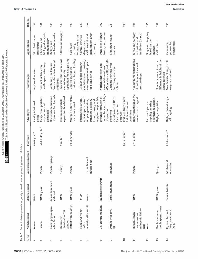
Tab
le5
Rece
ntdeve
lopments
ingravity-b
asedpassive
pumpingin
microfluidics
S.no
Analytes
used
Materials
used
Aux
iliaries
involved
Flow
rate
Adv
antages
Disad
vantages
App
lication
sRef.n
o
1Semen
PDMS
0.00
8mls�
1Readily
fabricated
device
Verylowow
rate
Vitro
fertilization
proced
ures
186
2Semen
PDMS,
glass
Pipe
tte
�20�
40mlh�1
Inexpe
nsive,p
ortable,
easy
tous
e,an
ddisp
osab
le
Doe
snot
isolateevery
motilesp
erm
effectively
Chem
ical
and
biolog
ical
analysis,
immun
oassay
187
3Blood
,physiological
saltsolution
Siliconlaminated
withresin
Pipe
tte,
syringe
One-stroke
fabrication
ofgroo
vesforch
annels
Com
biningthelaminar
ow
sat
themicroch
annel
isdifficu
lt
Biology
and
molecular
genetics
188
4Fluorescein
dissolvedin
BSA
solution
PDMS
Tub
ing
1mlh�1
Con
tinuo
uspa
rticle
sepa
ration
isachieved
Increasingtheow
rate
will
lead
tolowpu
rity
sepa
ration
foralarger
drop
Ultrasoun
dim
aging
189
5DMEM
withnodrug
PDMS,
glass
Pipe
tte
50mlpe
rda
yMultiplecu
ltureplates
canbe
incu
bated
Req
uiressp
ecialized
equipm
entforcellload
ing
Cell-b
ased
screen
ing,
cytotoxicity
assay
190
6Blood
andlysing
buffer
PMMA
Efficien
tlysisof
RBC
withsimplestructure
Cellularde
bris
cleaning
shou
ldbe
doneconstan
tly
Clinical
genetics,
diag
nostics
200
7Dim
ethylsiliconeoil
PDMS
Turntablean
dinfusion
set
Droplet
generation,
tran
sport,collision
,fusion
,mixing,
and
stop
pingarepo
ssible
Hardto
generatedrop
lets
foralongpe
riod
Cellresearch
and
high-con
tentdrug
screen
ing
191
8Cellculture
med
ium
Multilayers
ofPD
MS
Preven
tsform
ationof
airbu
bbles,up
to3da
ysof
operation
Nutrien
tde
pletionan
daccu
mulationof
waste
affects
theviab
ilityof
cells
Pred
iction
ofdrug
toxicity,c
ellcu
lture
192
9DMEM
with10
%FB
SPD
MSmem
bran
eInjection
Long-term
maintenan
ceof
HSE
sfordrug
testing
purposes
Unstab
leow
rate
with
decreasingreservoir
volume
Skin
drug
testing
stud
ies
22
1065
0mlmin
�1
Evaluatedrug
sun
der
uidiccellcu
lture
condition
s
193
11Hum
ancervical
carcinom
aan
dem
bryonic
kidn
eycells
PDMS
Pipe
tte
375mlmin
�1
Highly
bene
cial
asthe
rare
cells
aretrap
ped
Non
-uniform
distribu
tion
sof
uidicvelocities
and
pressu
redrop
s
Sign
allingpa
thway
activation
,and
inhibition(inSC
A)
194
12Water
Increasedpa
rticle
trap
pingon
using
aserpen
tinech
annel
Single-celltrap
ping
basedon
the
interest
195
13Motilean
dnon
-motilesp
erm,w
ater
PDMS,
glass
Syringe
Highly
compa
tible
Flow
isde
pende
nton
the
differen
cein
heigh
tof
the
source
reservoir
Cellcu
lture
197
14Trypa
nblue
and
lungcancercells
(A54
9)
Glass
subs
trate
Mechan
ical
obstacles
0.25
–4mls�
1Highly
efficien
tsingle-
celltrap
ping
Areade
nsity
ofsingle-cell
arrays
areredu
ced
Gen
omics,
proteo
mics,
secretom
ics
196
11668 | RSC Adv., 2020, 10, 11652–11680 This journal is © The Royal Society of Chemistry 2020
RSC Advances Review
Ope
n A
cces
s A
rtic
le. P
ublis
hed
on 2
3 M
arch
202
0. D
ownl
oade
d on
12/
11/2
021
12:4
1:56
AM
. T
his
artic
le is
lice
nsed
und
er a
Cre
ativ
e C
omm
ons
Attr
ibut
ion
3.0
Unp
orte
d L
icen
ce.
View Article Online
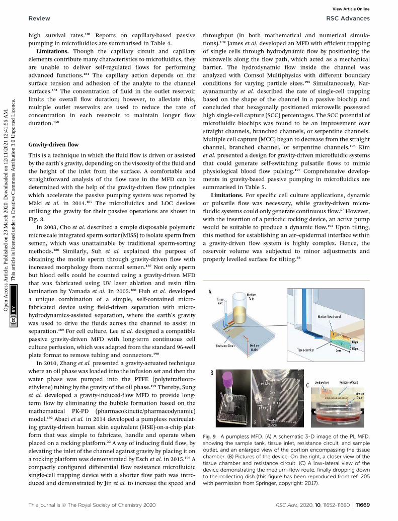
Review RSC Advances
Ope
n A
cces
s A
rtic
le. P
ublis
hed
on 2
3 M
arch
202
0. D
ownl
oade
d on
12/
11/2
021
12:4
1:56
AM
. T
his
artic
le is
lice
nsed
und
er a
Cre
ativ
e C
omm
ons
Attr
ibut
ion
3.0
Unp
orte
d L
icen
ce.
View Article Online
high survival rates.181 Reports on capillary-based passivepumping in microuidics are summarised in Table 4.
Limitations. Though the capillary circuit and capillaryelements contribute many characteristics to microuidics, theyare unable to deliver self-regulated ows for performingadvanced functions.184 The capillary action depends on thesurface tension and adhesion of the analyte to the channelsurfaces.151 The concentration of uid in the outlet reservoirlimits the overall ow duration; however, to alleviate this,multiple outlet reservoirs are used to reduce the rate ofconcentration in each reservoir to maintain longer owduration.158
Fig. 9 A pumpless MFD. (A) A schematic 3-D image of the PL MFD,showing the sample tank, tissue inlet, resistance circuit, and sampleoutlet, and an enlarged view of the portion encompassing the tissuechamber. (B) Pictures of the device. On the right, a closer view of thetissue chamber and resistance circuit. (C) A low-lateral view of thedevice demonstrating the medium-flow route, finally dropping downto the collecting dish (this figure has been reproduced from ref. 205with permission from Springer, copyright: 2017).
Gravity-driven ow
This is a technique in which the uid ow is driven or assistedby the earth's gravity, depending on the viscosity of the uid andthe height of the inlet from the surface. A comfortable andstraightforward analysis of the ow rate in the MFD can bedetermined with the help of the gravity-driven ow principleswhich accelerate the passive pumping system was reported byMaki et al. in 2014.185 The microuidics and LOC devicesutilizing the gravity for their passive operations are shown inFig. 8.
In 2003, Cho et al. described a simple disposable polymericmicroscale integrated sperm sorter (MISS) to isolate sperm fromsemen, which was unattainable by traditional sperm-sortingmethods.186 Similarly, Suh et al. explained the purpose ofobtaining the motile sperm through gravity-driven ow withincreased morphology from normal semen.187 Not only spermbut blood cells could be counted using a gravity-driven MFDthat was fabricated using UV laser ablation and resin lmlamination by Yamada et al. In 2005.188 Huh et al. developeda unique combination of a simple, self-contained micro-fabricated device using eld-driven separation with micro-hydrodynamics-assisted separation, where the earth's gravitywas used to drive the uids across the channel to assist inseparation.189 For cell culture, Lee et al. designed a compatiblepassive gravity-driven MFD with long-term continuous cellculture perfusion, which was adapted from the standard 96-wellplate format to remove tubing and connectors.190
In 2010, Zhang et al. presented a gravity-actuated techniquewhere an oil phase was loaded into the infusion set and then thewater phase was pumped into the PTFE (polytetrauoro-ethylene) tubing by the gravity of the oil phase.191 Thereby, Sunget al. developed a gravity-induced-ow MFD to provide long-term ow by eliminating the bubble formation based on themathematical PK-PD (pharmacokinetic/pharmacodynamic)model.192 Abaci et al. in 2014 developed a pumpless recirculat-ing gravity-driven human skin equivalent (HSE)-on-a-chip plat-form that was simple to fabricate, handle and operate whenplaced on a rocking platform.22 A way of inducing uid ow, byelevating the inlet of the channel against gravity by placing it ona rocking platform was demonstrated by Esch et al. in 2015.193 Acompactly congured differential ow resistance microuidicsingle-cell trapping device with a shorter ow path was intro-duced and demonstrated by Jin et al. to increase the speed and
This journal is © The Royal Society of Chemistry 2020
throughput (in both mathematical and numerical simula-tions).194 James et al. developed an MFD with efficient trappingof single cells through hydrodynamic ow by positioning themicrowells along the ow path, which acted as a mechanicalbarrier. The hydrodynamic ow inside the channel wasanalyzed with Comsol Multiphysics with different boundaryconditions for varying particle sizes.195 Simultaneously, Nar-ayanamurthy et al. described the rate of single-cell trappingbased on the shape of the channel in a passive biochip andconcluded that hexagonally positioned microwells possessedhigh single-cell capture (SCC) percentages. The SCC potential ofmicrouidic biochips was found to be an improvement overstraight channels, branched channels, or serpentine channels.Multiple cell capture (MCC) began to decrease from the straightchannel, branched channel, or serpentine channels.196 Kimet al. presented a design for gravity-driven microuidic systemsthat could generate self-switching pulsatile ows to mimicphysiological blood ow pulsing.197 Comprehensive develop-ments in gravity-based passive pumping in microuidics aresummarised in Table 5.
Limitations. For specic cell culture applications, dynamicor pulsatile ow was necessary, while gravity-driven micro-uidic systems could only generate continuous ow.57 However,with the insertion of a periodic rocking device, an active pumpwould be suitable to produce a dynamic ow.192 Upon tilting,this method for establishing an air–epidermal interface withina gravity-driven ow system is highly complex. Hence, thereservoir volume was subjected to minor adjustments andproperly levelled surface for tilting.22
RSC Adv., 2020, 10, 11652–11680 | 11669

Tab
le6
Rece
ntworksonhyd
rostatic
pressure-d
rive
npassive
pumpingtech
niquein
microfluidics
S.no
Analytes
used
Materials
used
Aux
iliaries
involved
Flow
rate
Adv
antages
Disad
vantages
App
lication
sRef.n
o
1Indicator
dyewith
bloo
dMicropipe
tteor
syringe
99nls�
1Lo
wcost,p
ortable
Equ
ilibrium
constan
taff
ects
theow
rate
Blood
plasma
sepa
ration
s,bloo
dtyping,
qualitative
immun
oassays
202
2DNAsample,
bloo
dPlastic
Pred
iction
forhigh-
viscositysolution
sis
difficu
lt
Drugdiscovery,
toxicology
203
3Hum
andermal
brob
last
neo
natal
cells
Silicontubingan
dsyringe
0.1–10
mlmin
�1
Con
stan
tow
rate
isachieved
Can
control
only
aslow
perfus
ionrate
andnot
suitab
leforallcells
Develop
men
tof
articial
skin
and
long-term
cell-
culture
204
4Sp
erm
with
phosph
atebu
ffered
solution
PDMS
Self-m
ovem
ent
Align
men
tan
dorientation
ofthe
sperm
ispo
ssible
Heigh
tch
ange
inthe
reservoirs
disturbs
theuid
ow
Clinical
labs
198
5Mou
setestis
tissue
PDMS
Micropipe
tte
0.05
mlmin
�1
Con
stan
tow
rate
for
alongrange
isob
served
Tissu
ecu
lturean
dorga
ncu
lture
205
11670 | RSC Adv., 2020, 10, 11652–11680
RSC Advances Review
Ope
n A
cces
s A
rtic
le. P
ublis
hed
on 2
3 M
arch
202
0. D
ownl
oade
d on
12/
11/2
021
12:4
1:56
AM
. T
his
artic
le is
lice
nsed
und
er a
Cre
ativ
e C
omm
ons
Attr
ibut
ion
3.0
Unp
orte
d L
icen
ce.
View Article Online
Hydrostatic pressure
Hydrostatic pressure is the force exerted by a uid at equilib-rium at a given point acting with equal magnitude in alldirections, due to the force of gravity. Hydrostatic pressureincreases in proportion to the depth measured from the surfacebecause of the increasing weight of the uid, exerting a down-ward force from above.201
Weigl et al. presented hydrostatic pressure-driven micro-uidic elements, including mixers, valves, and detectors thatwere employed in ultra-low-cost disposable qualitative andsemi-quantitative medical and environmental assays for thehome, office, and eld use, and for sample or reagent prepa-ration tools to provide processed liquids for downstreamanalysis.202 Subsequently, a microuidic cartridge was plan-ned for the extraction of small molecules by the hydrostaticpressure from the mixture of small and large molecules.203 Forthe culture medium, Marimuthu et al. developed a pumplessperfusion microuidic chip that could deliver a constant owrate with reduced pressure due to the intravenous (IV) setupused at the inlet, over the siphon-based gravity-driven micro-uidics.204 Later, Seo et al. employed hydrostatic pressure tosort motile sperms of three species, namely bull, mouse, andhuman, with an average sorting rate.198 The culturing of mousetestis tissue and spermatogenesis in a hydrostatic pressureenvironment were developed by Komeya et al. In addition,researchers used a resistance circuit to induce slow and long-lasting medium ow in the channel.205 MFD and LOC devicesemploying hydrostatic pressure for their passive operationsare shown in Fig. 9. Comprehensive reports on the hydrostaticpressure-driven passive pumping technique in microuidicsare summarised in Table 6.
Limitations. In a few cell cultures and trapping experiments,a more accurate ow rate was not obtained due to the reservoir
Fig. 10 A hybrid PDMS utilizing permeability and capillary effects forfluid flow (this figure has been reproduced from ref. 225 withpermission from IOP, copyright: 2009).
This journal is © The Royal Society of Chemistry 2020

Fig. 11 (i) Blood separation utilizing gas solubility and the permeability of PDMS. [A] Self-priming, self-contained, tether-free SIMBAS. [B]Schematic diagrams of the proposed device. (B-a) An overview of the experimental setup using the proposed device. The top layer is a PDMScover with an inlet and a tape-sealed outlet, and is bonded irreversibly with a bottom fluidic layer. (B-b) A top view and cross-section view. Theseparation chamber is divided into ten segments of equal volumes by nine phase guides at the bottom. Cylindrical posts are used to prevent thecollapse of the pneumatic chamber when it is evacuated by the manual syringes. w and S stand for the PDMS wall thickness and the overlap areabetween the pneumatic chamber A and the separation chamber, respectively. The overlap area (S), where the flux of air diffuses, is calculatedfrom the overlap length (l) multiplied by the chamber height (h). Drawings are not to scale. (B-c) Experimental steps. (ii) Different types ofvacuum-driven power-free micro-pumping methods utilizing the gas solubility or permeability of PDMS. (A-1) A 2D micro-pumping designutilizing the gas solubility of PDMS. A whole PDMS device is pre-evacuated in a vacuum environment. (A-2) A 3Dmicro-pumping design utilizingthe gas solubility of PDMS. A PDMS slab is pre-evacuated in a vacuum environment. See also Fig. 1A. (B-1) A 3D micro-pumping design utilizingthe gas permeability of PDMS. External vacuum pumps are connected to the ports in the control channels. (B-2) A 2D micro-pumping designutilizing the gas permeability of PDMS. A hand-held syringe can generate a vacuum environment (figures (i) and (ii) have been adapted from ref.214 with permission from the Royal Society of Chemistry, copyright: 2015).
Review RSC Advances
Ope
n A
cces
s A
rtic
le. P
ublis
hed
on 2
3 M
arch
202
0. D
ownl
oade
d on
12/
11/2
021
12:4
1:56
AM
. T
his
artic
le is
lice
nsed
und
er a
Cre
ativ
e C
omm
ons
Attr
ibut
ion
3.0
Unp
orte
d L
icen
ce.
View Article Online
design of the device. This could be modied with suitableadjustments in the diameter of the reservoir with the constantsupply of uids to the inlet.205
Vacuum driven
A vacuum refers to any space in which the pressure is lower thanatmospheric pressure (negative pressure). Vacuum-drivendevices use the ability of an MFD to suck the sample throughnegative pressure without any extra on/off-chip microuidicunits. Low vapour pressure and degassing become essential
This journal is © The Royal Society of Chemistry 2020
when the vacuum pressure falls below this vapour pressure.Degassing is the process of removal of any gas in the channelthrough permeability or solubility within the membrane togenerate a vacuum.206 Song et al. worked to produce a betterdemonstration of vacuum degassed ow in POC applicationsusing a PDMS-based material, coated with Parylene C.207
Later, Monahan et al. developed a channel outgassing tech-nique, where the channel was evacuated, and the negativepressure generated inside the channel assisted the ow with90% efficiency in eliminating bubble formation.208 A new power-free pumping method for PDMS MFD was developed by
RSC Adv., 2020, 10, 11652–11680 | 11671

Tab
le7
Rece
ntworksonvacu
um/perm
eationdrive
npassive
pumpingin
microfluidics
Sl.n
oAnalytes
used
Materials
used
Aux
iliaries
involved
Flow
rate
Mechan
isms
used
Adv
antages
Disad
vantages
App
lication
sRef.n
o
1Aqu
eous
uo
rescen
tbu
fferssp
iked
withuo
rescein
PDMS
Syringe
Degasseddriven
ow
Efficien
tat
elim
inatingair
bubb
les
Chan
nel
networks
arecomplex
inconstruction
208
2Fluo
rescen
tpa
rticle
solution
diluted
with
deion
ized
water
PDMS
Micropipe
tte
0.5–2nls�
1Degasseddriven
ow
Efficien
tde
position
and
twoan
alyses
canbe
condu
cted
onbo
thside
s
Not
suitab
lefor
continuo
usop
erations
Point-of-care,
single-us
ean
alytical
devices
75
3Human
serum
enrich
edwith
CRP
PDMSwithSU
-8ph
otoresistan
dglass
Pipe
tte
3–5nls�
1Degasseddriven
ow
Fast
assaytimeis
achieved
Usage
ofde
ionized
water
fordilution
Solution
mixingan
delectrop
horesis
209
4Blood
PDMS
0.5–2nlmin
�1
Degasseddriven
ow
Blood
analysisiscompu
ted
within
10minutes
Evacu
ationof
the
chan
nel
isnecessary
POCdiag
nosis
210
5Bluefood
colouringdy
ePD
MSplaced
onglassslides
Micropipe
tte
0.2to
3nls�
1Degasseddriven
ow
Degassingtimeis
very
high
Lab-on
-a-chip
devices
211
6Fo
oddy
esolution
PDMS
PDMSpu
mp
slab
,micropipe
tte
Degasseddriven
ow
Pumpslab
mus
tbe
evacua
tedovernight
LOCde
vices
andpo
int-of-
care
diag
nostic
212
7Blood
(rab
bit)
PDMS
Micro-needle
Degasseddriven
ow
Point-of-care
diag
nosis
213
8Bovineserum
PDMS
Sequ
ential
injection
Degasseddriven
ow
Noneedforsu
rface
treatm
ent
Pumpingpo
wer
decreasesat
afaster
rate
Point-of-care
diag
nosis
214
9Plasticpipe
tte
tips
Degasseddriven
ow
Self-pow
ered
andpo
rtab
leforeasy
convenience
Fluc
tuationof
the
ow
rate
isseen
Droplet-based
applicationsin
in-eldan
alysis
215
10Cottonthread
sInjection
mou
lded
2.2�
0.1mls�
1Degasseddriven
ow
Simple,
fast,c
heapan
dreliab
lein
theirap
plication
Loss
ofsamples
remains
unavoida
ble
216
11Fo
oddy
esolution
PDMS,
glass
subs
trate
0.92
mlmin
�1
Degasseddriven
ow
Longerpu
mpingdu
ration
towards
theou
tlet
Immed
iate
decayis
possible
dueto
diffus
ion
App
lication
swithlonger
workingpe
riod
217
12Aqu
eous/oil
microdrop
let
PDMS
Pipe
tte
250mlh�1
Degasseddriven
ow
Dramatic
improvem
entof
pumpingpe
rforman
ceBub
blegenerationis
observed
unde
rvacu
umde
siccators
Auton
omou
smicrodrop
let-
generation/
tran
sportan
dbiom
etrics
218
13Dye
PDMS
Pipe
tte
Degasseddriven
ow
Inexpe
nsive
intheir
constructionan
dim
plem
entation
Highly
expe
nsive
attheirmaintenan
cean
dinsu
fficien
tinstrumen
tation
Assay,p
rotein
crystallization
,drug
discovery,
and
combinatorial
chem
istry
219
14Water
droplet
PDMSon
glass
Injector
Perm
eation
driven
ow
Adh
esionis
achieved
throug
hlowpressu
reMixture
ofliqu
ids
cannot
bedriven
Con
centrate
collo
idsan
d22
1
11672 | RSC Adv., 2020, 10, 11652–11680 This journal is © The Royal Society of Chemistry 2020
RSC Advances Review
Ope
n A
cces
s A
rtic
le. P
ublis
hed
on 2
3 M
arch
202
0. D
ownl
oade
d on
12/
11/2
021
12:4
1:56
AM
. T
his
artic
le is
lice
nsed
und
er a
Cre
ativ
e C
omm
ons
Attr
ibut
ion
3.0
Unp
orte
d L
icen
ce.
View Article Online

Tab
le7
(Contd.)
Sl.n
oAnalytes
used
Materials
used
Aux
iliaries
involved
Flow
rate
Mechan
isms
used
Adv
antages
Disad
vantages
App
lication
sRef.n
o
crystallize
thosepa
rticles
15Water
droplet
PDMSwithtw
ouidreservoirs
Pipe
tte
Perm
eation
driven
ow
Form
ationof
layered
microstructures
atthe
centerdu
eto
perm
eability
Beadstacking,
chem
ical
concentration,
andpa
ssive
pumping
222
16Red
,blue,
and
greencoloured
uids
PDMS
Syringe
200nlmin
�1
Perm
eation
driven
ow
Bub
ble-free
ow
throug
hou
tthemem
bran
eCom
pletellingof
thech
annelsis
requ
ired
Drugde
livery
andmicro
total
analysis
223
17Dim
ethyl
sulfoxide
(DMSO
)
PDMSwith
autops
yneedle
Syringe
Perm
eation
driven
ow
Multipleuids
canbe
integrated
Bioan
alytical
application
224
18Plasmaof
bloo
dPD
MSan
dglass
slide
Syringe
Diffus
ion
Improved
accu
racy
and
precision
Evapo
ration
effects
werewitnessed
Drugscreen
ing
220
This journal is © The Royal Society of Chemistry 2020
Review RSC Advances
Ope
n A
cces
s A
rtic
le. P
ublis
hed
on 2
3 M
arch
202
0. D
ownl
oade
d on
12/
11/2
021
12:4
1:56
AM
. T
his
artic
le is
lice
nsed
und
er a
Cre
ativ
e C
omm
ons
Attr
ibut
ion
3.0
Unp
orte
d L
icen
ce.
View Article Online
Hosokawa et al. to overcome a signicant issue in the detectionof gold nanoparticle DNA analysis.75 Subsequently, they pre-sented an on-chip heterogeneous immunoassay with a simplestructure and operational procedure. Redissolution through themicrochannel walls developed the capacity to drive the solutionmovement and prevent air bubble trapping.209 Dimov et al. re-ported a microuidic blood analysis system where the plasmawas separated by trapping the RBC and WBC in a trench, andthe inlet uid was pumped due to the suction of the chamber, asa result of pre-evacuating the channel.210 Liang et al. developeda degassed channel with negative pressure to pump the uidirrespective of the surface tension of the uid. Before sampleloading, channel geometry, surface area, PDMS thickness,exposure area, vacuum degassing time, and post-vacuum idletime when the device was exposed to atmospheric conditionswere inspected.211 Eventually, Li et al. designed a PDMSmodular pump in a vacuum desiccator with high exibility andreduced fabrication complexity to create negative pressure inthe channel for sample movement.212
Furthermore, Li et al. developed a self-powered one-touchnger-press-activated blood extraction system based on thenegative pressure-driven force developed in the pre-vacuumactuator.213 Xu et al. designed a vacuum-driven power-freeMFD that depended on the gas solubility or permeability ofPDMS that restored the air inside it and encouraged the transferof air into a vacuum.214 Also, Li et al.worked on the developmentof a self-powered PDMS-based microuidic droplet generatorwith mono-dispersed droplet generation and multi-sampleintroduction in a controlled way.215 A simplied and inexpen-sive passive microuidic channel with excellent analyticalperformance to carry out microow injection analysis (mFIA)was investigated by Agustini et al.216 Subsequently, Liu et al.developed a paraffin wax and glass MFD through higher drivingpressure to maintain longer working times where the inlet wasexposed to air with a slower decline in ow rate.217 Li et al.proposed a high-pressure MFD to drive the uid using gaspermeation and suppressing the generation of bubbles underhigh temperatures.218 Then, a power-free and self-containeduid reactor array that performed parallel uid loading,metering and mixing through pre-degassed PDMS and thechange in capillary force due to sudden narrowing of thechannel cross-section was developed by Liu et al.219
Diffusion. This is the movement of solute particles froma region of higher concentration to a region of lower concen-tration due to the randommotion of atoms or molecules with orwithout a semi-permeable membrane. Warrick et al. comparedthe theoretical and experimental data of microchannels andstandard wells on the metrics of sample washing and experi-mental error in treatment concentrations.220
Permeation. Verneuil et al. described the process of waterpermeation in microstructures through silicone which hasa strong inuence on uid displacement.221 Randall et al.conrmed the use of lubrication approximation to solve gap-averaged velocity while transferring water from a single rect-angular channel into a PDMS using permeation-driven ows.222
Eddings et al. conrmed that the uid ow in a PDMS-basedMFD was generated through high gas permeability at the
RSC Adv., 2020, 10, 11652–11680 | 11673
RSC Advances Review
Ope
n A
cces
s A
rtic
le. P
ublis
hed
on 2
3 M
arch
202
0. D
ownl
oade
d on
12/
11/2
021
12:4
1:56
AM
. T
his
artic
le is
lice
nsed
und
er a
Cre
ativ
e C
omm
ons
Attr
ibut
ion
3.0
Unp
orte
d L
icen
ce.
View Article Online
membrane.223 The evaporation of water in the polymer wallsthrough permeation resulted in uid ow due to the excesspressure stored in the compartment.224 A hybrid PDMS utilizingpermeability for uid ow is shown in Fig. 10. MFD and LOCdevices using a vacuum for their passive operation are shown inFig. 11. Comprehensive developments in vacuum/permeation-driven passive pumping in microuidics are summarised inTable 7.
Limitations. Due to the limited air diffusion and hydro-phobicity of the PDMS material, the ow rates acquired werereduced to nanoliters per second. This could be enhanced byincreasing the surface area of the material used.223
Critical discussions and limitations
The evolution of new microuidic tools for genomics, proteo-mics, and metabolomics is progressing swily in research labo-ratories and will provide the motive for large-scale production.Passive ow methodologies, such as surface-tension-driven ow,capillary-based ow, gravity-driven ow, hydrostatic-pressure-driven ow, and osmosis-driven ow techniques are found tobe suitable in assisting the ow without any external sources.Despite the benecial properties of PDMS that permitted its fastenactment in applied elds, there are several limitations in usingthe material in biomedical research.226 The control of uid owover space and timewith sufficient accuracy was the fundamentalchallenge in designing MFDs.227 The initial fabrication of MFDsrequired clean-room facilities for silicon or glass devices whichwere eliminated by polymers and elastomers devices. However,PDMS was limited by its ability to withstand high temperature,difficulty in developing complex multi-layered 3D-congureddevices, and incompatibility with organic solvents and lowmolecular weight organic solutes due to their surface chem-istry.228 The usage of inert chemicals and utilization of high-throughput methods for manufacturing and permeability limitthe application of PDMS devices in a few cases.229 Evaporationaffects the application of microuidics in various domains.230
This could be overridden by maintaining a uniform surfacethroughout the entire channel area. In pressure-driven tech-niques, variation in pressure is noted due to the difference inchannel length and utilization of different ngers at theinlet.119,127 This unbalanced pressure may lead to backow, fol-lowed by clogging or the entire destruction of the device. Hence,a uniform pressure needs to be maintained for a long period.This can be achieved by osmosis-driven MFDs. However, inosmosis-driven MFDs, the osmotic reagent had to be refreshed atregular intervals, which restricted their applications.145 In addi-tion to that, selection of a suitable membrane is necessary tomaintain the pH and to avoid clogging when biological cells orbiomolecules are used.143 Hence, capillary-based passive owtechniques are used as they depend only on the design andmaterial characteristics of the MFD. On the other hand, in someinstances, due to a drop in ow rate, essential pressure predictionat each step decreased sensitivity in capillary-based passive owtechniques.151,165 This could be averted by selection of suitablematerials with the ability of spontaneous sample lling in thecolumn.231 Because of this, under many circumstances, gravity-
11674 | RSC Adv., 2020, 10, 11652–11680
driven techniques are adopted, but they generate an unstableor decreasing ow rate, which was further eliminated by main-taining an appropriate reservoir volume and proper inlet pres-sure.22,198 Whereas hydrostatic-pressure-driven techniques arelimited by the development of Laplace pressure at the air–liquidinterface due to the affinity between the liquid, the atmosphere,and the reservoir parameters.232 Another listed shortcoming wasthe linear pressure drop with time. These errors could be avoi-ded, if the pressure difference was obtained by varying the alti-tude of the liquid to the atmospheric interface in the properway.197 They could be eliminated by using a vacuum MFD;nevertheless evacuation is necessary to drive the uid in order toreduce the pressure within the channel. Due to the presence ofhigh pressure initially, the suction of the uid is higher andgradually decreases as the pressure decreases. Hence a syringepump is used to maintain a constant ow in the device. Thisadditional requirement can be neglected by the use of simplecapillary force.211 Based on the study performed, the vacuum-driven techniques with complex construction were not suitablefor continuous operation due to the evaporation effect and theloss of sample in a few cases.75,208,216 Besides the above-mentionedlimitations, these methods found numerous clinical applica-tions, because they use ultra-low volumes of biouids for pro-cessing and can be accomplished quickly and efficiently.
Industrial perspectives
One of the promising types of assistance of microuidics isfound in fast, reliable, and accurate POC diagnostic devices.Detection and diagnostics of communicable diseases candecrease the mortality rate in many developing and less devel-oped countries. As reported by the World Health Organization(WHO), nearly 46% of new tuberculosis case are not detected,causing over 3 million incidences to be missed annually.233,234
Also, according to a recent report by WHO, the lack of properdiagnostic capacity is a signicant challenge in monitoringeffective service coverage. As an example, cholera was estimatedto have infected 1.3–4 million people annually and to havecaused 21 000–143 000 deaths each year during 2008–2012. Butthe average annual numbers of cases and deaths reported toWHO were only 313 000 and 5700, respectively. One of themajor issues is the lack of diagnostic capacity, which results inthe exact burden of the disease being unknown, thus making itdifficult to take preventive measures.235 Although manyresearchers in the microuidic domain are focusing on devel-oping diagnosis and detection devices – searching for a fewrelated keywords such as diagnosis, detection, and pathogendetection in LOC, bio-microuidics, and biomedical micro-devices resulted in nearly 3000 papers –many of the products donot end up on the market. One major issue in this regard istransforming common expensive sample delivery systems inlaboratories, such as syringe pumps, into passive and low-costdelivery systems to meet the needs of the market in devel-oping and less developed countries. To analyse the status ofcurrent commercialized MFDs, we delved into the circle data-base of uFluidix Inc (http://circle.uuidix.com). The databaseincludes a list of registered start-ups offering microuidic
This journal is © The Royal Society of Chemistry 2020

Review RSC Advances
Ope
n A
cces
s A
rtic
le. P
ublis
hed
on 2
3 M
arch
202
0. D
ownl
oade
d on
12/
11/2
021
12:4
1:56
AM
. T
his
artic
le is
lice
nsed
und
er a
Cre
ativ
e C
omm
ons
Attr
ibut
ion
3.0
Unp
orte
d L
icen
ce.
View Article Online
products. Nearly 85% of the analysed start-ups in the diagnos-tics industry were utilizing a passive method for sampledelivery. This clearly emphasizes the importance of passivetechniques for industrial sectors.
Conclusion and future directions
Microuidics is articulated as a multidisciplinary research eldthat requires basic knowledge in uidics, micromachining,electromagnetics, materials, and chemistry to nd their rele-vance in the pharmaceutical industry, diagnosis, healthcare,and life science research. LOC is one of the essential applica-tions of microuidics, and is also a revolutionary tool for manyvarieties of applications in chemical and biological analyses dueto its fascinating advantages (speed, low cost, simplicity, andself-testing) over conventional chemical or laboratoryequipment.
Microuidics covers the science of uidic behaviours atmicro/nanoscales employed in design engineering, simulation,and fabrication of uidic devices. It is the backbone of biolog-ical or biomedical microelectromechanical systems (BioMEMS)and the LOC concept, as most biological analysis involves uidtransport and reaction. MFDs have been operated in inkjetprinting, blood analysis, biochemical detection, chemicalsynthesis, drug screening/delivery, protein analysis, DNAsequencing, and so on. Several different MFDs have beendeveloped with basic structures analogous to macroscale uidicdevices. Such devices include microuidic valves, microuidicpumps, and microuidic mixers. Active devices are usuallymore expensive, due to their functional and fabricationcomplexities. However, it has been very challenging to imple-ment these actuation schemes fully at the microscale, owing tothe requirements for high voltages, electromagnets, etc. Typi-cally, passive MFDs do not require an external power source,where control is instituted by the energy drawn from theworking uid, or based purely on surface effects, such as surfacetension or uid pressure, with high reliability due to the lack ofmechanical wear and tear. Hence, upcoming industrial sectorsrely on passive methods to achieve better results in a composedway.
MFDs offer very repeatable performance, once the under-lying phenomena are well understood and characterized. Theyare well suited to bioMEMS applications, as they can handleseveral microuidic manipulation sequences. They are also wellsuited to the low-cost mass production of disposable MFDs tospecically work with blood. In addition, inexpensive andsimple fabrication techniques can promote the use of paper-based MFD in various research elds, such as drug testingand viral detection.
Passive MFDs with high throughput, high ow rate, reducedoperation time and easy equipment handling are expected tohave protable outcomes. Therefore, MFDs with passivemethods are designed in such a way as to offer a wide range ofoptimizations that can be performed within the channel andreservoir dimensions for employment to certain specic appli-cations with better ow rates. In the future, device progress willfocus on developing new materials for substrates in such a way
This journal is © The Royal Society of Chemistry 2020
as to overcome the drawbacks of currently existing devices.Passive systems cannot maintain constant ow rates. Hence,systems with constant ow rates are expected to be developed asan advantageous method. In addition, a low operation timeremains an essential parameter. A reduction in running timecan be demonstrated to be the crucial factor on which to focusduring upcoming developments. Future work is expected tofocus on exploring these listed areas, so that microuidics cannd application in many other elds to satisfy growingdemands and needs.
Conflicts of interest
There are no conicts of interest to declare.
Acknowledgements
The authors would like to thank and acknowledge the Funda-mental Research Grant Scheme of the Ministry of Energy,Science, Technology, Environment and Climate Change (MES-TECC), Malaysia (FRGS RDU190108).
References
1 E. Lauga, M. Brenner and H. Stone, in Handbook ofExperimental Fluid Mechanics, Springer, Heidelberg, 2007,ch. 19, pp. 1219–1240, DOI: 10.1007/978-3-540-30299-5_19.
2 H. A. Stone, A. D. Stroock and A. Ajdari, Annu. Rev. FluidMech., 2004, 36, 381–411.
3 G. M. Whitesides, Nature, 2006, 442, 368–373.4 P. N. Nge, C. I. Rogers and A. T. Woolley, Chem. Rev., 2013,113, 2550–2583.
5 L. Zhu, G. Jiang, S. Wang, C. Wang, Q. Li, H. Yu, Y. Zhou,B. Zhao, H. Huang, W. Xing, K. Mitchelson, J. Cheng,Y. Zhao and Y. Guo, J. Clin. Microbiol., 2010, 48, 3654–3660.
6 P. Singh, J. Comput. Appl., 2017, 8, 8–11.7 L. R. Volpatti and A. K. Yetisen, Trends Biotechnol., 2014, 32,347–350.
8 V. Chokkalingam, J. Tel, F. Wimmers, X. Liu, S. Semenov,J. Thiele, C. G. Figdor and W. T. Huck, Lab Chip, 2013, 13,4740–4744.
9 K. K. Jain, Pharmacogenomics, 2000, 1, 289–307.10 Y. Ghallab and W. Badawy, IEEE Circ. Syst. Mag., 2004, 4, 5–
15.11 V. Saggiomo and A. H. Velders, Adv. Sci., 2015, 2, 1500125.12 P. S. Dittrich and A. Manz, Nat. Rev. Drug Discovery, 2006, 5,
210–218.13 S. K. Sia and L. J. Kricka, Lab Chip, 2008, 8, 1982–1983.14 G. J. Kost, N. K. Tran, M. Tuntideelert,
S. Kulrattanamaneeporn and N. Peungposop, Am. J. Clin.Pathol., 2006, 126, 513–520.
15 M. H. Wu, S. B. Huang and G. B. Lee, Lab Chip, 2010, 10,939–956.
16 L. Y. Wu, D. Di Carlo and L. P. Lee, Biomed. Microdevices,2008, 10, 197–202.
17 L. Kang, B. G. Chung, R. Langer and A. Khademhosseini,Drug Discovery Today, 2008, 13, 1–13.
RSC Adv., 2020, 10, 11652–11680 | 11675
RSC Advances Review
Ope
n A
cces
s A
rtic
le. P
ublis
hed
on 2
3 M
arch
202
0. D
ownl
oade
d on
12/
11/2
021
12:4
1:56
AM
. T
his
artic
le is
lice
nsed
und
er a
Cre
ativ
e C
omm
ons
Attr
ibut
ion
3.0
Unp
orte
d L
icen
ce.
View Article Online
18 C. Kleinstreuer, J. Li and J. Koo, Int. J. Heat Mass Transfer,2008, 51, 5590–5597.
19 Z.-B. Liu, Y. Zhang, J.-J. Yu, A. F.-T. Mak, Y. Li and M. Yang,Sens. Actuators, B, 2010, 143, 776–783.
20 Y. C. Toh, T. C. Lim, D. Tai, G. Xiao, D. van Noort and H. Yu,Lab Chip, 2009, 9, 2026–2035.
21 L. Yu, M. C. Chen and K. C. Cheung, Lab Chip, 2010, 10,2424–2432.
22 H. E. Abaci, K. Gledhill, Z. Guo, A. M. Christiano andM. L. Shuler, Lab Chip, 2015, 15, 882–888.
23 S. R. Khetani, D. R. Berger, K. R. Ballinger, M. D. Davidson,C. Lin and B. R. Ware, J. Lab. Autom., 2015, 20, 216–250.
24 J. M. Martel and M. Toner, Sci. Rep., 2013, 3, 3340.25 J. Kr$uuml$ger, K. Singh, A. O$apos$Neill, C. Jackson,
A. Morrison and P. O$apos$Brien, J. Micromech. Microeng.,2002, 12, 486–494.
26 P. S. Dittrich and P. Schwille, Anal. Chem., 2003, 75, 5767–5774.
27 S.-Y. Yang, S.-K. Hsiung, Y.-C. Hung, C.-M. Chang, T.-L. Liaoand G.-B. Lee, Meas. Sci. Technol., 2006, 17, 2001–2009.
28 J. C. Baret, O. J. Miller, V. Taly, M. Ryckelynck, A. El-Harrak,L. Frenz, C. Rick, M. L. Samuels, J. B. Hutchison,J. J. Agresti, D. R. Link, D. A. Weitz and A. D. Griffiths,Lab Chip, 2009, 9, 1850–1858.
29 A. A. Bhagat, H. Bow, H. W. Hou, S. J. Tan, J. Han andC. T. Lim, Med. Biol. Eng. Comput., 2010, 48, 999–1014.
30 C. W. t. Shields, C. D. Reyes and G. P. Lopez, Lab Chip, 2015,15, 1230–1249.
31 J. Autebert, B. Coudert, F. C. Bidard, J. Y. Pierga, S. Descroix,L. Malaquin and J. L. Viovy, Methods, 2012, 57, 297–307.
32 X. Zhu, L. Yi Chu, B. H. Chueh, M. Shen, B. Hazarika,N. Phadke and S. Takayama, Analyst, 2004, 129, 1026–1031.
33 W. Gu, X. Zhu, N. Futai and B. S. Cho and S. Takayama,presented in part at the 7th lnternational Conference onMiniaturized Chemical and Blochemlcal Analysts Systems,California USA, 2004.
34 P. J. Hung, P. J. Lee, P. Sabounchi, R. Lin and L. P. Lee,Biotechnol. Bioeng., 2005, 89, 1–8.
35 S. L. Peterson, A. McDonald, P. L. Gourley and D. Y. Sasaki,J. Biomed. Mater. Res., Part A, 2005, 72, 10–18.
36 P. Lee, R. Lin, J. Moon and L. P. Lee, Biomed. Microdevices,2006, 8, 35–41.
37 R. Gomez-Sjoberg, A. A. Leyrat, D. M. Pirone, C. S. Chen andS. R. Quake, Anal. Chem., 2007, 79, 8557–8563.
38 S. M. Ong, C. Zhang, Y. C. Toh, S. H. Kim, H. L. Foo,C. H. Tan, D. van Noort, S. Park and H. Yu, Biomaterials,2008, 29, 3237–3244.
39 V. Lecault, M. Vaninsberghe, S. Sekulovic, D. J. Knapp,S. Wohrer, W. Bowden, F. Viel, T. McLaughlin,A. Jarandehei, M. Miller, D. Falconnet, A. K. White,D. G. Kent, M. R. Copley, F. Taghipour, C. J. Eaves,R. K. Humphries, J. M. Piret and C. L. Hansen, Nat.Methods, 2011, 8, 581–586.
40 M. Mehling and S. Tay, Curr. Opin. Biotechnol., 2014, 25, 95–102.
11676 | RSC Adv., 2020, 10, 11652–11680
41 R. Sista, Z. Hua, P. Thwar, A. Sudarsan, V. Srinivasan,A. Eckhardt, M. Pollack and V. Pamula, Lab Chip, 2008, 8,2091–2104.
42 F. B. Myers and L. P. Lee, Lab Chip, 2008, 8, 2015–2031.43 E. K. Sackmann, A. L. Fulton and D. J. Beebe, Nature, 2014,
507, 181–189.44 D. B. Weibel and G. M. Whitesides, Curr. Opin. Chem. Biol.,
2006, 10, 584–591.45 P. Gravesen, J. Branebjerg and O. S. Jensen, J. Micromech.
Microeng., 1993, 3, 168–182.46 H. A. Stone and S. Kim, AIChE J., 2001, 47, 1250–1254.47 J. C. McDonald, D. C. Duffy, J. R. Anderson, D. T. Chiu,
H. Wu, O. J. A. Schueller and G. M. Whitesides,Electrophoresis, 2000, 21, 27–40.
48 T. Fujii, Microelectron. Eng., 2002, 61–62, 907–914.49 J. C. McDonald and G. M. Whitesides, Acc. Chem. Res., 2002,
35, 491–499.50 J. Kuncova-Kallio and P. J. Kallio, Conf. Proc. IEEE Eng. Med.
Biol. Soc., 2006, 1, 2486–2489.51 J. Zhou, A. V. Ellis and N. H. Voelcker, Electrophoresis, 2010,
31, 2–16.52 T. C. Merkel, V. I. Bondar, K. Nagai, B. D. Freeman and
I. Pinnau, J. Polym. Sci., 2000, 38, 415–434.53 D. J. Beebe, G. A. Mensing and G. M. Walker, Annu. Rev.
Biomed. Eng., 2002, 4, 261–286.54 G. S. Fiorini and D. T. Chiu, Biotechniques, 2005, 38, 429–
446.55 J.-H. Tsai and L. Lin, Sens. Actuators, A, 2002, 97–98, 665–
671.56 M. M. Teymoori and E. Abbaspour-Sani, Sens. Actuators, A,
2005, 117, 222–229.57 C. K. Byun, K. Abi-Samra, Y. K. Cho and S. Takayama,
Electrophoresis, 2014, 35, 245–257.58 P. H. Huang, N. Nama, Z. Mao, P. Li, J. Rufo, Y. Chen, Y. Xie,
C. H. Wei, L. Wang and T. J. Huang, Lab Chip, 2014, 14,4319–4323.
59 A. Terray, J. Oakey and D. W. Marr, Science, 2002, 296, 1841–1844.
60 T. Vestad, D. W. M. Marr and J. Oakey, J. Micromech.Microeng., 2004, 14, 1503–1506.
61 H.-P. Chou, M. A. Unger and S. R. Quake, Biomed.Microdevices, 2001, 3, 323–330.
62 V. Studer, A. Pepin, Y. Chen and A. Ajdari, Analyst, 2004,129, 944–949.
63 C.-Y. Lee, G.-B. Lee, J.-L. Lin, F.-C. Huang and C.-S. Liao, J.Micromech. Microeng., 2005, 15, 1215–1223.
64 M. G. Pollack, R. B. Fair and A. D. Shenderov, Appl. Phys.Lett., 2000, 77, 1725–1726.
65 X. Wang, C. Cheng, S. Wang and S. Liu, Microuid.Nanouid., 2009, 6, 145.
66 C. Sung Kwon, M. Hyejin and K. Chang-Jin, J.Microelectromech. Syst., 2003, 12, 70–80.
67 F. Xia, S. Tadigadapa and Q. M. Zhang, Sens. Actuators, A,2006, 125, 346–352.
68 M. Shen, L. Dovat andM. A. M. Gijs, Sens. Actuators, B, 2011,154, 52–58.
This journal is © The Royal Society of Chemistry 2020

Review RSC Advances
Ope
n A
cces
s A
rtic
le. P
ublis
hed
on 2
3 M
arch
202
0. D
ownl
oade
d on
12/
11/2
021
12:4
1:56
AM
. T
his
artic
le is
lice
nsed
und
er a
Cre
ativ
e C
omm
ons
Attr
ibut
ion
3.0
Unp
orte
d L
icen
ce.
View Article Online
69 M. E. Harmon, M. Tang and C. W. Frank, Polymer, 2003, 44,4547–4556.
70 J. Berthier, P. Dubois, P. Clementz, P. Claustre, C. Peponnetand Y. Fouillet, Sens. Actuators, A, 2007, 134, 471–479.
71 D. H. Jun, W. Y. Sim and S. S. Yang, Sens. Actuators, A, 2007,139, 210–215.
72 D. T. Wong, J. Am. Dent. Assoc., 2006, 137, 313–321.73 S. Upadhyaya and P. R. Selvaganapathy, Lab Chip, 2010, 10,
341–348.74 L. Gervais, N. de Rooij and E. Delamarche, Adv. Mater.,
2011, 23, H151–H176.75 K. Hosokawa, K. Sato, N. Ichikawa and M. Maeda, Lab Chip,
2004, 4, 181–185.76 S. K. Sia and G. M. Whitesides, Electrophoresis, 2003, 24,
3563–3576.77 T. Bayraktar and S. B. Pidugu, Int. J. Heat Mass Transfer,
2006, 49, 815–824.78 S. Haeberle and R. Zengerle, Lab Chip, 2007, 7, 1094–1110.79 E. W. Young and D. J. Beebe, Chem. Soc. Rev., 2010, 39,
1036–1048.80 C. H. Ahn and J.-W. Choi, in Springer Handbook of
Nanotechnology, Springer Handbook, 2010, pp. 503–530,DOI: 10.1007/978-3-642-02525-9_18.
81 W. Su, X. Gao, L. Jiang and J. Qin, J. Chromatogr. A, 2015,1377, 13–26.
82 S. Tripathi, Y. V. B. Varun Kumar, A. Prabhakar, S. S. Joshiand A. Agrawal, J. Micromech. Microeng., 2015, 25, 083001.
83 V. Narayanamurthy, S. Nagarajan, A. a. Y. Firus Khan,F. Samsuri and T. M. Sridhar, Anal. Methods, 2017, 9,3751–3772.
84 J. H. W. Guo and W. van der Wijngaart, presented in part atthe 20th International Conference on Miniaturized Systems forChemistry and Life Sciences, Ireland, 2016.
85 W. Guo, J. Hansson and W. van der Wijngaart, Microsyst.Nanoeng., 2018, 4, 2.
86 W. Guo, J. Hansson and W. van der Wijngaart, presented inpart at the 2017 IEEE 30th International Conference on MicroElectro Mechanical Systems (MEMS), Las Vegas, NV, USA,Jan. 2017, 2017, vol. 22–26.
87 Microuidics Market by Application (Genomics,Proteomics, Capillary Electrophoresis, IVD (POC, ClinicalDiagnostics), Drug Delivery, Microreactor, Lab Tests),Component (Chips, Pump, Needle), Material (Polymer,Glass, Silicon) - Global Forecast to 2023, https://www.marketsandmarkets.com/Market-Reports/microuidics-market-1305.html?gclid¼CjwKCAiArK_fBRABEiwA0gOOc_eZ1aIgVylO7GQPYakcbg9F1lH6zEf-lw6jRwrmW0UWaEBWePRfCRoCw3MQAvD_BwE, 2019.
88 G. Gabrielse, X. Fei, L. A. Orozco, R. L. Tjoelker, J. Haas,H. Kalinowsky, T. A. Trainor and W. Kells, Phys. Rev. Lett.,1990, 65, 1317–1320.
89 S. Yd and S. C. Maroo, Langmuir, 2016, 32, 8593–8597.90 V. B. Makhijani, A. J. Reich, A. Puntambekar, C. Hong and
C. Ahn, TechConnect Briefs, 2001, 1, 266–269.91 G. Walker and D. J. Beebe, Lab Chip, 2002, 2, 131–134.92 G. M. Walker and D. J. Beebe, Lab Chip, 2002, 2, 57–61.
This journal is © The Royal Society of Chemistry 2020
93 C. Chien-Fu, K. Shih-Chi, C. Chin-Chou and T. Fan-Gang,presented in part at the Sixteenth Annual InternationalConference on Micro Electro Mechanical Systems, 2003,MEMS-03 Kyoto, IEEE, Kyoto, Japan, Japan, 2003.
94 T. Ward, M. Faivre, M. Abkarian and H. A. Stone,Electrophoresis, 2005, 26, 3716–3724.
95 Y. C. Tan, J. S. Fisher, A. I. Lee, V. Cristini and A. P. Lee, LabChip, 2004, 4, 292–298.
96 Y. Yang and Y. C. Liang, J. Power Sources, 2007, 165, 185–195.
97 E. Berthier and D. J. Beebe, Lab Chip, 2007, 7, 1475–1478.98 I. Meyvantsson, J. W. Warrick, S. Hayes, A. Skoien and
D. J. Beebe, Lab Chip, 2008, 8, 717–724.99 J. Ju, J. Y. Park, K. C. Kim, H. Kim, E. Berthier, D. J. Beebe
and S.-H. Lee, J. Micromech. Microeng., 2008, 18, 087002.100 Y. Du, J. Shim, M. Vidula, M. J. Hancock, E. Lo, B. G. Chung,
J. T. Borenstein, M. Khabiry, D. M. Cropek andA. Khademhosseini, Lab Chip, 2009, 9, 761–767.
101 I. J. Chen, E. C. Eckstein and E. Lindner, Lab Chip, 2009, 9,107–114.
102 P. J. Resto, B. J. Mogen, E. Berthier and J. C. Williams, LabChip, 2010, 10, 23–26.
103 P. J. Resto, B. Mogen, F. Wu, E. Berthier, D. Beebe andJ. Williams, J. Visualized Exp., 2009, e1329.
104 I. J. Chen and E. Lindner, Anal. Chem., 2009, 81, 9955–9960.105 A. L. McPherson and G. M. Walker, Microuid. Nanouid.,
2010, 9, 897–904.106 J. P. Puccinelli, X. Su and D. J. Beebe, JALA Charlottesv Va,
2010, 15, 25–32.107 B. G. Chung and J. Choo, Electrophoresis, 2010, 31, 3014–
3027.108 G. Lin and A. P. Lee, Ann. N. Y. Acad. Sci., 2010, 1190, 186–
192.109 E. Berthier, J. Warrick, B. Casavant and D. J. Beebe, Lab
Chip, 2011, 11, 2060–2065.110 P. J. Resto, E. Berthier, D. J. Beebe and J. C. Williams, Lab
Chip, 2012, 12, 2221–2228.111 J. T. Kuo, C. Li and E. Meng, Conf. Proc. IEEE Eng. Med. Biol.
Soc., 2014, 2014, 4415–4418.112 T. E. de Groot, K. S. Veserat, E. Berthier, D. J. Beebe and
A. B. Theberge, Lab Chip, 2016, 16, 334–344.113 K. Javadi, H. Moezzi-Rae, V. Goodarzi-Ardakani, A. Javadi
and R. Miller, Colloids Surf., A, 2017, 518, 30–45.114 K. Iwai, R. D. Sochol and L. Lin, presented in part at the 2011
IEEE 24th International Conference on Micro ElectroMechanical Systems, Cancun, Mexico, 2011.
115 H. Jonsson, Microuidics for lab-on-a-chip applications,MSc thesis, Lund University, 2004.
116 R. H. Liu, M. A. Stremler, K. V. Sharp, M. G. Olsen,J. G. Santiago, R. J. Adrian, H. Aref and D. J. Beebe, J.Microelectromech. Syst., 2000, 9, 190–197.
117 C. H. Ahn, A. Puntambekar, S. M. Lee, H. J. Cho andC.-C. Hong, presented in part at the Micro Total AnalysisSystems 2000, 2000.
118 N. L. Jeon, D. T. Chiu, C. J. Wargo, H. Wu, I. S. Choi,J. R. Anderson and G. M. Whitesides, Biomed.Microdevices, 2002, 4, 117–121.
RSC Adv., 2020, 10, 11652–11680 | 11677
RSC Advances Review
Ope
n A
cces
s A
rtic
le. P
ublis
hed
on 2
3 M
arch
202
0. D
ownl
oade
d on
12/
11/2
021
12:4
1:56
AM
. T
his
artic
le is
lice
nsed
und
er a
Cre
ativ
e C
omm
ons
Attr
ibut
ion
3.0
Unp
orte
d L
icen
ce.
View Article Online
119 B. M. Rush, K. D. Dorfman, H. Brenner and S. Kim, Ind. Eng.Chem. Res., 2002, 41, 4652–4662.
120 J. Moorthy and D. J. Beebe, Lab Chip, 2003, 3, 62–66.121 Y. Hu, C. Werner and D. Li, J. Fluids Eng., 2003, 125, 871–
879.122 C. o.-K. Chen and C.-C. Cho, Chem. Eng. Sci., 2008, 63,
3081–3087.123 H. Jiang, X. Weng and D. Li,Microuid. Nanouid., 2010, 10,
941–964.124 K. Hattori, S. Sugiura and T. Kanamori, J. Lab. Autom., 2013,
18, 437–445.125 N. Davey and A. Neild, J. Colloid Interface Sci., 2011, 357,
534–540.126 J. D. Tice, A. V. Desai, T. A. Bassett, C. A. Apblett and
P. J. A. Kenis, RSC Adv., 2014, 4, 51593–51602.127 K. Iwai, K. C. Shih, X. Lin, T. A. Brubaker, R. D. Sochol and
L. Lin, Lab Chip, 2014, 14, 3790–3799.128 L. Xu, H. Lee and K. W. Oh,Microuid. Nanouid., 2014, 17,
745–750.129 T. Kokalj, Y. Park, M. Vencelj, M. Jenko and L. P. Lee, Lab
Chip, 2014, 14, 4329–4333.130 G. S. Jeong, J. Oh, S. B. Kim, M. R. Dokmeci, H. Bae,
S. H. Lee and A. Khademhosseini, Lab Chip, 2014, 14,4213–4219.
131 V. Tandon, W. S. Kang, T. A. Robbins, A. J. Spencer,E. S. Kim, M. J. McKenna, S. G. Kujawa, J. Fiering,E. E. Pararas, M. J. Mescher, W. F. Sewell andJ. T. Borenstein, Lab Chip, 2016, 16, 829–846.
132 S. Lee, H. Kim, W. Lee and J. Kim, Micro and Nano SystemsLetters, 2018, 6, 1.
133 E. S. Kim, E. Gustenhoven, M. J. Mescher, E. E. Pararas,K. A. Smith, A. J. Spencer, V. Tandon, J. T. Borenstein andJ. Fiering, Lab Chip, 2014, 14, 710–721.
134 T. Satoh, G. Narazaki, R. Sugita, H. Kobayashi, S. Sugiuraand T. Kanamori, Lab Chip, 2016, 16, 2339–2348.
135 X. Zhang, X. Wang, K. Chen, J. Cheng, N. Xiang and Z. Ni,RSC Adv., 2016, 6, 31639–31646.
136 B. U. Moon, N. Abbasi, S. G. Jones, D. K. Hwang andS. S. Tsai, Anal. Chem., 2016, 88, 3982–3989.
137 H. Ryu, K. Choi, Y. Qu, T. Kwon, J. S. Lee and J. Han, Anal.Chem., 2017, 89, 5549–5556.
138 A. M. Nightingale, G. W. Evans, P. Xu, B. J. Kim,S. U. Hassan and X. Niu, Lab Chip, 2017, 17, 1149–1157.
139 F. Dal Dosso, T. Kokalj, J. Belotserkovsky, D. Spasic andJ. Lammertyn, Biomed. Microdevices, 2018, 20, 44.
140 B. Liu, M. Li, B. Tian, X. Yang and J. Yang, Microuid.Nanouid., 2018, 22, 94.
141 M. Boyd-Moss, S. Baratchi, M. Di Venere andK. Khoshmanesh, Lab Chip, 2016, 16, 3177–3192.
142 C. J. C. Biscombe, Angew. Chem., Int. Ed., 2017, 56, 8338–8340.
143 B. R. Bruhn, T. B. Schroeder, S. Li, Y. N. Billeh, K. W. Wangand M. Mayer, PLoS One, 2014, 9, e91350.
144 B. T. Good, C. N. Bowman and R. H. Davis, J. ColloidInterface Sci., 2007, 305, 239–249.
145 Z. R. Xu, C. G. Yang, C. H. Liu, Z. Zhou, J. Fang andJ. H. Wang, Talanta, 2010, 80, 1088–1093.
11678 | RSC Adv., 2020, 10, 11652–11680
146 J. Y. Park, S. K. Kim, D. H. Woo, E. J. Lee, J. H. Kim andS. H. Lee, Stem Cells, 2009, 27, 2646–2654.
147 A. L. Paguirigan and D. J. Beebe, Integr. Biol., 2009, 1, 182–195.
148 J. Y. Park, S. J. Yoo, L. Patel, S. H. Lee and S. H. Lee,Biorheology, 2010, 47, 165–178.
149 S.-H. Kim, K. Kim, M. Go and J. Y. Park, J. Micromech.Microeng., 2018, 28, 125005.
150 S. Herrlich, S. Spieth, S. Messner and R. Zengerle, Adv. DrugDelivery Rev., 2012, 64, 1617–1627.
151 D. Juncker, H. Schmid, U. Drechsler, H. Wolf, M. Wolf,B. Michel, N. de Rooij and E. Delamarche, Anal. Chem.,2002, 74, 6139–6144.
152 K. Hosokawa and M. Maeda, IEEJ Transactions on Sensorsand Micromachines, 2003, 123, 23–24.
153 S.-J. Kim, Y. B. Shin, D.-S. Lee, H. Yang, K. Kim, S. H. Parkand Y. T. Kim, presented in part at the 7th lnternationalConference on Miniaturized Chemical and BlochemlcalAnalysts Systems, California USA, 2003.
154 N. Ichikawa, K. Hosokawa and R. Maeda, J. Colloid InterfaceSci., 2004, 280, 155–164.
155 M. Zimmermann, H. Schmid, P. Hunziker andE. Delamarche, Lab Chip, 2007, 7, 119–125.
156 J. W. Suk and J.-H. Cho, J. Micromech. Microeng., 2007, 17,N11–N15.
157 Y. Zhu and K. Petkovic-Duran, Microuid. Nanouid., 2009,8, 275–282.
158 N. S. Lynn and D. S. Dandy, Lab Chip, 2009, 9, 3422–3429.159 L. Gervais and E. Delamarche, Lab Chip, 2009, 9, 3330–
3337.160 S. Mukhopadhyay, S. S. Roy, A. Mathur, M. Tweedie and
J. A. McLaughlin, J. Micromech. Microeng., 2010, 20, 055018.161 A. H. Ng, U. Uddayasankar and A. R. Wheeler, Anal. Bioanal.
Chem., 2010, 397, 991–1007.162 Y. C. Kim, S.-H. Kim, D. Kim, S.-J. Park and J.-K. Park, Sens.
Actuators, B, 2010, 145, 861–868.163 F. R. de Souza, G. L. Alves and W. K. Coltro, Anal. Chem.,
2012, 84, 9002–9007.164 T. Horiuchi, T. Miura, Y. Iwasaki, M. Seyama, S. Inoue,
J. Takahashi, T. Haga and E. Tamechika, Sensors, 2012,12, 7095–7108.
165 S. J. Kim, S. Paczesny, S. Takayama and K. Kurabayashi, LabChip, 2013, 13, 2091–2098.
166 K. Kistrup, C. E. Poulsen, P. F. Østergaard, K. B. Haugshøj,R. Taboryski, A. Wolff and M. F. Hansen, J. Micromech.Microeng., 2014, 24, 125007.
167 J. Berthier, K. A. Brakke, D. Gosselin, A. G. Bourdat,G. Nonglaton, N. Villard, G. Laffite, F. Boizot, G. Costaand G. Delapierre,Microuid. Nanouid., 2014, 18, 919–929.
168 H. Madadi, J. Casals-Terre and M. Mohammadi,Biofabrication, 2015, 7, 025007.
169 C. Nie, A. J. Frijns, R. Mandamparambil and J. M. denToonder, Biomed. Microdevices, 2015, 17, 47.
170 S. Mukhopadhyay, J. P. Banerjee, S. S. Roy, S. K. Metya,M. Tweedie and J. A. McLaughlin, Surf. Rev. Lett., 2017,24, 1750041.
This journal is © The Royal Society of Chemistry 2020
Review RSC Advances
Ope
n A
cces
s A
rtic
le. P
ublis
hed
on 2
3 M
arch
202
0. D
ownl
oade
d on
12/
11/2
021
12:4
1:56
AM
. T
his
artic
le is
lice
nsed
und
er a
Cre
ativ
e C
omm
ons
Attr
ibut
ion
3.0
Unp
orte
d L
icen
ce.
View Article Online
171 M. Huet, M. Cubizolles and A. Buhot, Biosens. Bioelectron.,2017, 93, 110–117.
172 F. Bunge, S. van den Driesche and M. J. Vellekoop,Microuid. Nanouid., 2016, 20, 95.
173 T. Wu, Z. Luo, W. Ding, Z. Cheng and L. He, Microuid.Nanouid., 2017, 21, 129.
174 Y. Zhai, A. Wang, D. Koh, P. Schneider and K. W. Oh, LabChip, 2018, 18, 276–284.
175 J. Xie, H. Su, J. Liao and J. Liu, Microuid. Nanouid., 2017,21, 106.
176 N. Vasilakis, K. I. Papadimitriou, H. Morgan andT. Prodromakis, Microuid. Nanouid., 2017, 21.
177 T. Akyazi, N. Gil-Gonzalez, L. Basabe-Desmonts, E. Castano,M. C. Morant-Minana and F. Benito-Lopez, Sens. Actuators,B, 2017, 247, 114–123.
178 J.-P. Frimat, B. Schurink and R. Luttge, J. Vac. Sci. Technol.,B: Nanotechnol. Microelectron.: Mater., Process., Meas.,Phenom., 2017, 35, 06GA01.
179 L. Mei, M. Jin, S. Xie, Z. Yan, X. Wang, G. Zhou, A. van denBerg and L. Shui, Lab Chip, 2018, 18, 2806–2815.
180 B. Kim, S. Oh, S. Shin, S. G. Yim, S. Y. Yang, Y. K. Hahn andS. Choi, Anal. Chem., 2018, 90, 8254–8260.
181 E. Moonen, R. Luttge and J.-P. Frimat, Microelectron. Eng.,2018, 197, 1–7.
182 H. Tachibana, M. Saito, K. Tsuji, K. Yamanaka, L. Q. Hoaand E. Tamiya, Sens. Actuators, B, 2015, 206, 303–310.
183 M. M. Aeinehvand, F. Ibrahim, S. W. Harun, W. Al-Faqheri,T. H. Thio, A. Kazemzadeh and M. Madou, Lab Chip, 2014,14, 988–997.
184 A. Olanrewaju, M. Beaugrand, M. Yaa and D. Juncker, LabChip, 2018, 18, 2323–2347.
185 A.-J. Maki, S. Hemmila, J. Hirvonen, N. N. Girish,J. Kreutzer, J. Hyttinen and P. Kallio, J. Fluids Eng., 2015,137, 21105.
186 B. S. Cho, T. G. Schuster, X. Zhu, D. Chang, G. D. Smith andS. Takayama, Anal. Chem., 2003, 75, 1671–1675.
187 R. S. Suh, N. Phadke, D. A. Ohl, S. Takayama andG. D. Smith, Hum. Reprod. Update, 2003, 9, 451–461.
188 H. Yamada, Y. Yoshida and N. Terada, Jpn. J. Appl. Phys.,2005, 44, 8739–8741.
189 D. Huh, J. H. Bahng, Y. Ling, H. H. Wei, O. D. Kripfgans,J. B. Fowlkes, J. B. Grotberg and S. Takayama, Anal.Chem., 2007, 79, 1369–1376.
190 P. J. Lee, N. Ghorashian, T. A. Gaige and P. J. Hung, JALACharlottesv Va, 2007, 12, 363–367.
191 K. Zhang, Q. Liang, S. Ma, T. He, X. Ai, P. Hu, Y. Wang andG. Luo, Microuid. Nanouid., 2010, 9, 995–1001.
192 J. H. Sung, C. Kam and M. L. Shuler, Lab Chip, 2010, 10,446–455.
193 M. B. Esch, J. M. Prot, Y. I. Wang, P. Miller, J. R. Llamas-Vidales, B. A. Naughton, D. R. Applegate andM. L. Shuler, Lab Chip, 2015, 15, 2269–2277.
194 D. Jin, B. Deng, J. X. Li, W. Cai, L. Tu, J. Chen, Q. Wu andW. H. Wang, Biomicrouidics, 2015, 9, 014101.
195 J. James, M. Sushmitha, R. Premkumar, V. Narayanamurthyand R. Kalpana, presented in part at the 2017 International
This journal is © The Royal Society of Chemistry 2020
conference on Microelectronic Devices, Circuits and Systems(ICMDCS), Vellore, India, 2017.
196 V. Narayanamurthy, T. Lee, A. a. Khan, F. Samsuri,K. Mohamed, H. Hamzah and M. Baharom, Fluids, 2018,3, 51.
197 S.-J. Kim, X. Zhu and S. Takayama, in Microtechnology forCell Manipulation and Sorting, Springer, 2017, pp. 175–192, DOI: 10.1007/978-3-319-44139-9_6.
198 D.-b. Seo, Y. Agca, Z. C. Feng and J. K. Critser, Microuid.Nanouid., 2007, 3, 561–570.
199 S. M. Knowlton, M. Sadasivam and S. Tasoglu, TrendsBiotechnol., 2015, 33, 221–229.
200 P. J. Shah, M. Dimaki and W. E. Svendsen, presented in partat the TRANSDUCERS 2009 - 2009 International Solid-StateSensors, Actuators and Microsystems Conference, Denver,CO, USA, 2009.
201 Benets of Water Therapy, https://www.friendshiphaven.org/benets-of-water-therapy/.
202 B. H. Weigl, R. Bardell, T. Schulte and C. Williams,presented in part at the Micro Total Analysis Systems 2000,2000.
203 B. H. Weigl, R. L. Bardell, N. Kesler and C. J. Morris,Fresenius. J. Anal. Chem., 2014, 371, 97–105.
204 M. Marimuthu and S. Kim, Anal. Biochem., 2013, 437, 161–163.
205 M. Komeya, K. Hayashi, H. Nakamura, H. Yamanaka,H. Sanjo, K. Kojima, T. Sato, M. Yao, H. Kimura, T. Fujiiand T. Ogawa, Sci. Rep., 2017, 7, 15459.
206 W. Wu, Analyst, 2018, 143, 4819–4835.207 Q. Song, J. Sun, Y. Mu, Y. Xu, Q. Zhu and Q. Jin, Sens.
Actuators, B, 2018, 256, 1122–1130.208 J. Monahan, A. A. Gewirth and R. G. Nuzzo, Anal. Chem.,
2001, 73, 3193–3197.209 K. Hosokawa, M. Omata, K. Sato and M. Maeda, Lab Chip,
2006, 6, 236–241.210 I. K. Dimov, L. Basabe-Desmonts, J. L. Garcia-Cordero,
B. M. Ross, Y. Park, A. J. Ricco and L. P. Lee, Lab Chip,2011, 11, 845–850.
211 D. Y. Liang, A. M. Tentori, I. K. Dimov and L. P. Lee,Biomicrouidics, 2011, 5, 24108.
212 G. Li, Y. Luo, Q. Chen, L. Liao and J. Zhao, Biomicrouidics,2012, 6, 14118–1411816.
213 C. G. Li, M. Dangol, C. Y. Lee, M. Jang and H. Jung, LabChip, 2015, 15, 382–390.
214 L. Xu, H. Lee, D. Jetta and K. W. Oh, Lab Chip, 2015, 15,3962–3979.
215 C. Li, J. Xu and B. Ma, Microuid. Nanouid., 2014, 18,1067–1073.
216 D. Agustini, M. F. Bergamini and L. H. Marcolino-Junior,Anal. Chim. Acta, 2017, 951, 108–115.
217 B. Liu, D. Koh, A. Wang, P. Schneider and K. W. Oh,Microsyst. Technol., 2017, 24, 2035–2043.
218 Y. Li, Y. Jiang, K. Wang and W. Wu, Anal. Chem., 2018, 90,11925–11932.
219 Y. Liu and G. Li, Sci. Rep., 2018, 8, 13664.220 J. Warrick, I. Meyvantsson, J. Ju and D. J. Beebe, Lab Chip,
2007, 7, 316–321.
RSC Adv., 2020, 10, 11652–11680 | 11679
RSC Advances Review
Ope
n A
cces
s A
rtic
le. P
ublis
hed
on 2
3 M
arch
202
0. D
ownl
oade
d on
12/
11/2
021
12:4
1:56
AM
. T
his
artic
le is
lice
nsed
und
er a
Cre
ativ
e C
omm
ons
Attr
ibut
ion
3.0
Unp
orte
d L
icen
ce.
View Article Online
221 E. Verneuil, A. Buguin and P. Silberzan, Europhys. Lett.,2004, 68, 412–418.
222 G. C. Randall and P. S. Doyle, Proc. Natl. Acad. Sci. U. S. A.,2005, 102, 10813–10818.
223 M. A. Eddings and B. K. Gale, J. Micromech. Microeng., 2006,16, 2396–2402.
224 D. B. Weibel, A. C. Siegel, A. Lee, A. H. George andG. M. Whitesides, Lab Chip, 2007, 7, 1832–1836.
225 M. Johnson, G. Liddiard, M. Eddings and B. Gale, J.Micromech. Microeng., 2009, 19, 095011.
226 D. T. Chiu, A. J. deMello, D. Di Carlo, P. S. Doyle, C. Hansen,R. M. Maceiczyk and R. C. R. Wootton, Chem, 2017, 2, 201–223.
227 D. C. Leslie, C. J. Easley, E. Seker, J. M. Karlinsey, M. Utz,M. R. Begley and J. P. Landers, Nat. Phys., 2009, 5, 231–235.
11680 | RSC Adv., 2020, 10, 11652–11680
228 Y. T. Atalay, S. Vermeir, D. Witters, N. Vergauwe,B. Verbruggen, P. Verboven, B. M. Nicolaı andJ. Lammertyn, Trends Food Sci. Technol., 2011, 22, 386–404.
229 M.-C. Belanger and Y. Marois, J. Biomed. Mater. Res., 2001,58, 467–477.
230 S. Kachel, Y. Zhou, P. Scharfer, C. Vrancic, W. Petrich andW. Schabel, Lab Chip, 2014, 14, 771–778.
231 M. Hitzbleck and E. Delamarche,Micromachines, 2013, 4, 1–8.
232 P. Shah, X. Zhu, C. Chen, Y. Hu and C. Z. Li, Biomed.Microdevices, 2014, 16, 35–41.
233 Global tuberculosis report 2014, http://www.who.int/iris/handle/10665/137094, accessed March, 2019.
234 R. McNerney, Diagnostics, 2015, 5, 200–209.235 W. H. Organization, World health statistics 2016: monitoring
health for the SDGs sustainable development goals, WorldHealth Organization, 2016.
This journal is © The Royal Society of Chemistry 2020