advisory for aeronautics
TRANSCRIPT

E X P E R m N T A L INVESTIGATION OF AIR&IDE PERFORMANCE
OF LIQITID.-METAL TO AIR HEXT EXCHANGERS . . .
By Louis Gedeon, -Charles W. Conant,. a& Samuel J. Kaufman
Lewis Flight Propulsion Laboratory Cleveland, Ohio.
CLASSIFICATION CHANGED
"_""" """" lJN!clrnF*O- "" . .
NATIONAL ADVISORY COMMITTEE FOR AERONAUTICS
WASHINGTON March 16,1956
-
NACA RM E55L05 L
EXPERIMENTAL INVESTIGATION OF AIR-SIDE PERFORMANCE
' OF LIQUID-METAL TO AIR HEAT EXCHANGERS
By Louis Gedeon, Charles W. Conant, and Samuel J. Kauf'man
€€eat-transfer and pressure-drop data were experimentally obtained for the air side of a liquid-metal t o air, shell-and-tube heat exchanger. Tests were conducted i n a 500 kilowatt facil i ty using sodium as the shell-side heating f luid. Because of w e l d failures, only isothermal-
1 pressure-drop data f o r a f inned-tube heat exchanger me included. . Exchanger-inlet-air temperature was varied from 70° tr> 6OOO F for Reynolds
nunibers of 7000 t o 115,OOO. Average i n l e t sdium temperatures w e r e main- tained between 80O0 and U0Oo F. D
Air-side heat-transfer data for the shell-and-tube heat exchanger were correlated by the familiar Nusselt relation corrected for length- to-diameter ratio. Tests were run with sodium hadug a relative large amount of owgen and with sodium having a reduced oxygen content. The latter gave results tha t were i n good agreement with the recommended l ine.
Pressure-drop data for the shell-and-tube heat exchanger were com- . pared with the K&m&n-Nikuradse r e l a t ion fo r f r i c t ion f ac to r and Reynolds
nmiber. Isothermal data and low Reynolds nuiber data with heat transfer gave good agreement with the recommended l ine . High Reynolds n-er data with heat transfer gave a f r i c t i o n factor t h a t f e l l considerably below the line. Isothermal-pressure-drop data f o r a finned-tube heat exchanger were compared with an analytical investigation for f lat plates and found t o be 55 percent higher than predicted by the analysis for f lat plates.
IN'IBOWCTION
A 500-kilowatt t e s t f a c i l i t y f o r use in evaluat ing the performance
Lewis laboratory. This report describes the test f a c i l i t y and presents data obtained for two heat exchangers.
- of liquid-metal t o air heat exchangers has been constructed at the NACA
S

2 NACA RM E5SL05
The first heat exchanger tested is the conventional shell-and-tube type with sodium as the she l l fluid. H e a t is t r amfe r red t o t he air flowing through the tubes. This type of exchanger w a s selected for the i n i t i a l t e s t s because of ease of fabrication.
. c
The second heat exchanger bui l t was of the finned-tube type, i n which sodium flowed through the tubes while air flowed over the f in6 and banks of tubes. Because of weld failures, only isothermal-pressure-drop data is reported for the finned-tube heat exchanger. .
The 5 0 0 - k i l m t t f a c i l i t y is designed so that flight condition6 at d
Mach 1.5 at an a l t i t ude of 30,000 feet with a compressor pressure ra t io w of 7.0 can be simulated. I n addition, varying the in le t - a i r temperature and pressure allows t es t ing at other flight conditions. Maximum operat- ing conditions for the loop are as follms:
*
A i r flax, lb/aec . . . . . . . . . . . . . . . . . . . . . . . . . . 4 Inlet-air temperature, 6~ . . . . . . . . . . . . . . . . . . . . . 700 Sodium flow, lb/sec . . . . . . . . . . . . . . . . . . . . . . . 6 In l e t sodium temperature, . . . . . . . . . . . . . . . . . . . . 1500 Heat-transfer rate, Btu/sec . . . . . . . . . . . . . . . . . . . . 475 The data reported he re in were obtained aver a range of each of the oper- ating variables.
Additional heat: exchangers of varied design me being constructed for test . The ultimate goal i s t o d e t e r d m which liquld-metal t o air heat exchanger best flrlfills the following; requireneents for nuclear- powered aircraft :
(1) High-thermal efficiency
(2) Lar air-side pressure b o p
(3) Low weight
(4) E a s e of fabr icat ion
(5) Rel iab i l i ty
APPARATUS
A schematic diagram of the t e s t f a c i l i t y is sham i n figure 1. So- dium i s circulated from the sump tank by a ve r t i ca l shaft centrifugal 9
pump through the electric-resistance heater, heat exchanger, volume meas- uring tank, and back t o the SUMP tank. The sodium loop i e designed t o d r a i n by gravi ty into the sump tank. i.
NACA RM E55L05 - 3
Regulating valves, orifice, fuel burner, mixing baffles, and * straightening vanes make up the air s ide of the system. Proper heat-
exchanger-inlet-air conditions are set by positioning the th ro t t l i ng valves and adjust ing the fuel flow t o . t he burner.
Test Faci l i ty
Details of the various components of the test f a c i l i t y are given i n the following paragraphs.
Sump tank. - The sump tank is constructed of AIS1 300 series s ta in- less steel, 36 inches i n d i m t e r and 33 inches deep. The wall is made of a 3/8-inch plate , the bottom is a 1/2-inch plate, and a 3/4-inch cover plate supports the centrifugal pump. About 500 pounds of sodium are con-
a blanket over the sodium surface. Because the Wgen content of the
insure that a minimum of oxygen is introduced into the system, the argon
sodium-potassium alloy.
4(. 0 Id P ta ined in the sump tank. Originally oil-pumped nitrogen gas w a s used as r;' R nitrogen was greater than expected, argon was substituted. In order to u
-7 gas is fur ther purif ied by bubbling it through two tanks of l iqu id
h S w pump. - A vertical sh&t centrifugal pump c i r c l ik t e s l i qu id sodlum through the loop. A t a rated speed of 1800 rpm, the pump capacity is 50 gpm. Since the pump shaft, housing, impeller, and supports are irrrmersed i n sodium they are made of s ta in less steel. The bearings and shaft supports are located above the sump tank. An air-cooled graphite- impregnated asbestos seal mounted on the cover p la t e i s used t o prevent gas leakage around the pump shaft . A labyrinth-type slinger r ing is fas tened to the pump shaft t o minilnize sodium leakage.
The pump is bel t dr iven by a 30-horsepower variable-speed direct- current motor which is powered and controlled by a motor-generator set.
Electric-resistance heater. - In order to obtain a desired scdium temperature, heat is added in the electric-resistance heater. AIS1 type 304 stainless-steel tubing, 30 feet long, $ inches i n diam&er with a
0.125-inch wall, i s bent i n a double return section (fig. 1). The hot bus-bar connection i s at the midpoint and the end points Elre at ground po ten t i a l t o r e s t r i c t t he e l ec t r i c cu r ren t flow to the heater sect ion. Since sodium is an e lec t r ic conductor, heat is generated i n the sodium flaTing through the heater 88 w e l l as in the pipe. The main heater is encased i n a t r a n s i t e box packed with magnesia insulation.
4
.) Elec t r ic system. - Electr ic power from a 2400 vol t , 60 cycle l ine is supplied t o t h e main heater through a power transformer. The parer i s controlled by a saturable reactor on the primary s ide of the trans- former. An air-cooled coaxial bus bar connects the transformer t o t h e
*

4 NACA RM E55L05
main heater. The capacity of the electric system is 500 kilowatts at a maximum of 25 volts across the main heater. Volts, amperes, and watts are read on the transforlner secondary. Current is measured by t h e w e of a 20,000/5 ampere current transformer.
Volume measuring tank. - The volume measuring tank is constructed of 3/8-inch stainless steel, 18 inches in diameter, and 30 inches deep. A plunger-type valve actuated by an air-driven piston closes the exit l i n e at the bottom of the tank. Three electric contact points insulated from the tank are ins ta l led a t known depths. An electric stopclock is + actuated by the sodium making contact with the lowest contact point. Upon reaching the middle or highest contact the clock i s stopped and the drain valve opens. A thermocouple located inside the tank indicates the so- dim temperature. With the time required t o f i l l a designated volumz and the density of sodium at the recorded teqerature given, the sodium flow ra t e i s determined. A sieve-type splash guard located abwe the sodium entrance maintains a level surface.
r( m WJ
. .
An overflow l ine runs from the top of the volume measuring tank t o the sump tank. Two functions of t h i s l i n e are (1) sodium i s allowed t o flow beck in to the sump tank in the event the plunger valve fails to open, and (2) it serves as a vent line when the volume tank i e being f i l l e d .
Piping and preheaters. - All piping' between elements is &inch
stainless-steel tubing. Ring-joint flanges are used for easy disasseribly. To eliminate the possibil i ty of leaks, extreme care is taken in the alinement of the flanges. The flanges are neither preheated nor insulated t o reduce the probability of the bol ts expanding and therefore loosening the connection.
2
. . . . . .. .. - . L . .I I" .L . . I . . . . -.. "_ Michrome V heating wire threaded in ceramic bead6 and wrapped around
each element of the up t o temperature. transf or=.
Fi l ter tank. - i n the f i l ter tank,
sodium loop serve as preheaters to bring the system Power is supplied to each heater by a variable
In o rder to charge the loop, sodium is first melted and then argon pressure i e w e d t o f o r c e t h e l i q u i d
sodium through a 5-micron micrometallic filter in to the SUMP tank. The f i l t e r tank is used, per iodical ly , to keep the sodium oxide content t o a minimum. I n this process the surrrp tank i s heated t o looOo F. Sodium i s then t ransferred to the filter tank where it cools t o about 300° F. Sodium oxide precipitates out and the filtered sodium i s returned t o the sump tank.
NACA RM E55L05 m
5
A i r tunnel. - A i r - f l o w rates and pressures are regulated by control
rate of 4 pounds per second is available at a pressure of 120 pounds per square inch. The air-fluw rate is measured by a standard sharp-edge orifice i n a 6-inch l ine. The air i s heated t o a desired temperature by an altered 5-35 burner-can assembly. The air then flows through a set of mixing baffles, straightening vanes, a bellmouthed-entrance section and in tb the test section from which it is exhausted t o t h e atmosphere through a muffler. Total-temperature, total-pressure, and s t a t i c - pressure measurements are taken before and after the heat exchanger.
. valves located before and after the heat exchanger. A maximum air-flow
Temperature and pressure measurements. - Air-inlet and -outlet and sodium-inlet and -outlet temperatures are measured by means of c h r o ~ ~ l e l - a l ~ l thermocouples. In add i t ion t o these, each section of pipe is spotted with chromel-alumel thermocouples of 24 gage. A l l tempera- tures me read on a self-balancing, indicating-type potentiometer. A rake made up of nine total-temperature thermocouples and nine total- pressure tubes is located before and a f t e r the heat exchanger. The ther- mocouples and pressure tubes are positioned i n the center of three equal
“1 concentric areas for the shell-and-tube heat exchanger and the center of nine equal rectangular areas for the finned-tube heat exchanger. Four static-pressure taps are located on the tunnel w a l l i n t h e same plane as the total-pressure tubes. Total and s ta t ic pressures are indicated on banks of mercurf manometers which are photographed f o r each run i n order t o simplify the recording of data and t o provide a permanent record.
L;
SaSety devices. - Thermocouples attached to cutout switches- are used to detect
(1) Overtemperature of main heater
(2) Overtemperature of sump tank
(3) Overtemperature of burner-outlet air
(4) Undertemperature of sump tank
(5) Undertemperature of burner-outlet air
Any of these wi l l shut dam the system. Insuff ic ient bus-bar cool- ing air and pump speed w i l l also shut down the system.
A sodium leak and flame detector designed at NACA is a l so employed i n this system. Th i s uni t is immediately downstream of t he heat exchanger.
junction with filters tha t absorb a l l l i gh t except the spectral l ine of burning sodium. The flame detector i s located on the tunnel w a l l and sees a l l the exchanger-exit air. The leak-detecting unit views a sample of exchanger-outlet a i r that i s passed mer a bunsen flame. A sodium f i re i n t h e air tunnel or a t the Bunsen burner will shut down the system.
.) Both the flame- and leak-detecting uni ts use photoelectric tubes in con-

6 NACA RM E55LO5
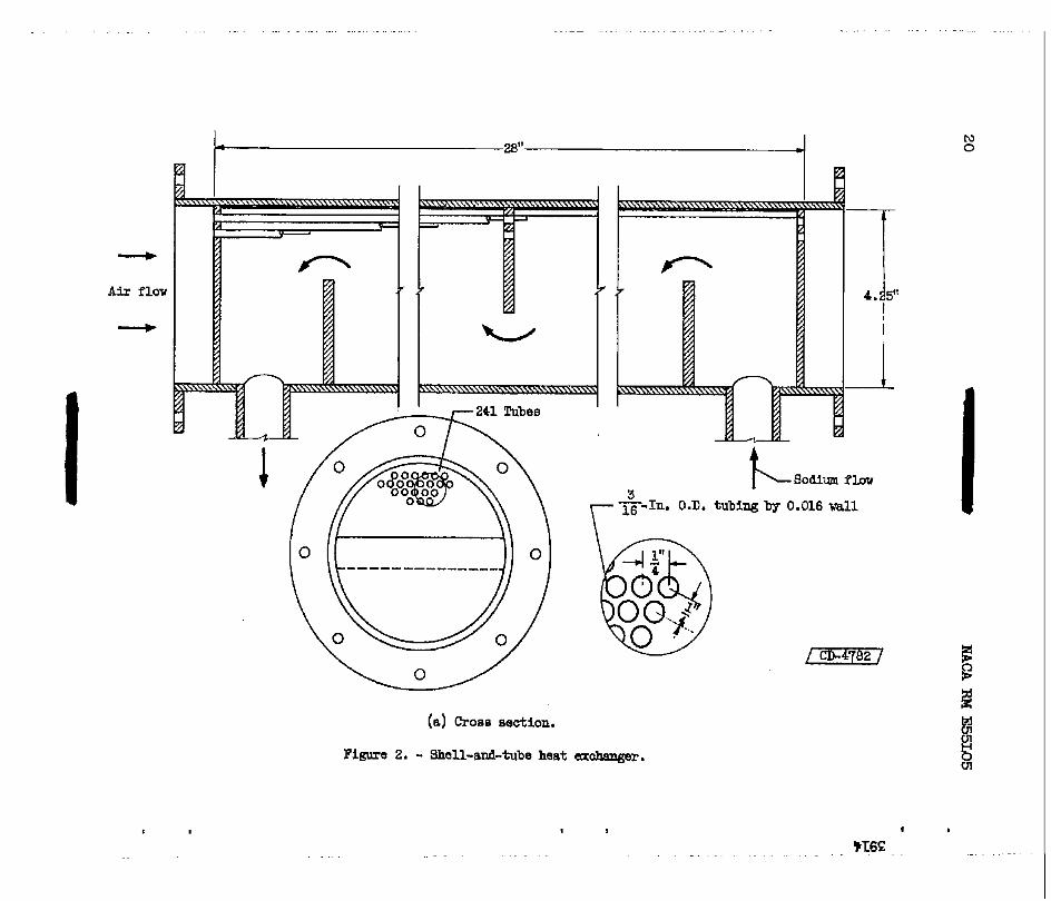
Shell-and-tube heat exchanger. - The first heat exchanger tes ted in this loop is of the shell-and-tube design ( f ig . 2) . Sodium flaws i n the s h e l l over the bundle of tubes as the air passes counterflaw through the tubes. The sodium side has 3 baffles extending slightly past the center of t he she l l making a crossflow-counterflm arrangement. The shell. is constructed of 1/8-inch AIS1 300-series stainless-steel plate, 29 inches long and 4.25 inches i n diameter. The r ing around the shell sham i n figure 2(b) i s an expansion joint .
A t o t a l of 241 tubes, 28 inches long, are spaced i n a triangular array on 1/4-inch centers. A cloaeup photograph of the header and tubee is shown i n figure 2(c). The stainless-steel tubes, which are 3/16 inch in outside diameter with a 0.016-inch wall are hel iarc welded t o 1/8- inch header plates.
Since sodium is one of the exchanger f luids , extreme care was taken i n a l l welds. The exchanger was pressure checked t o f i n d any large leaks. I n order t o locate the smaller leaks that cannot be detected by a prea- sure check, a mass-spectrometer-type leak detector WBB used.
L
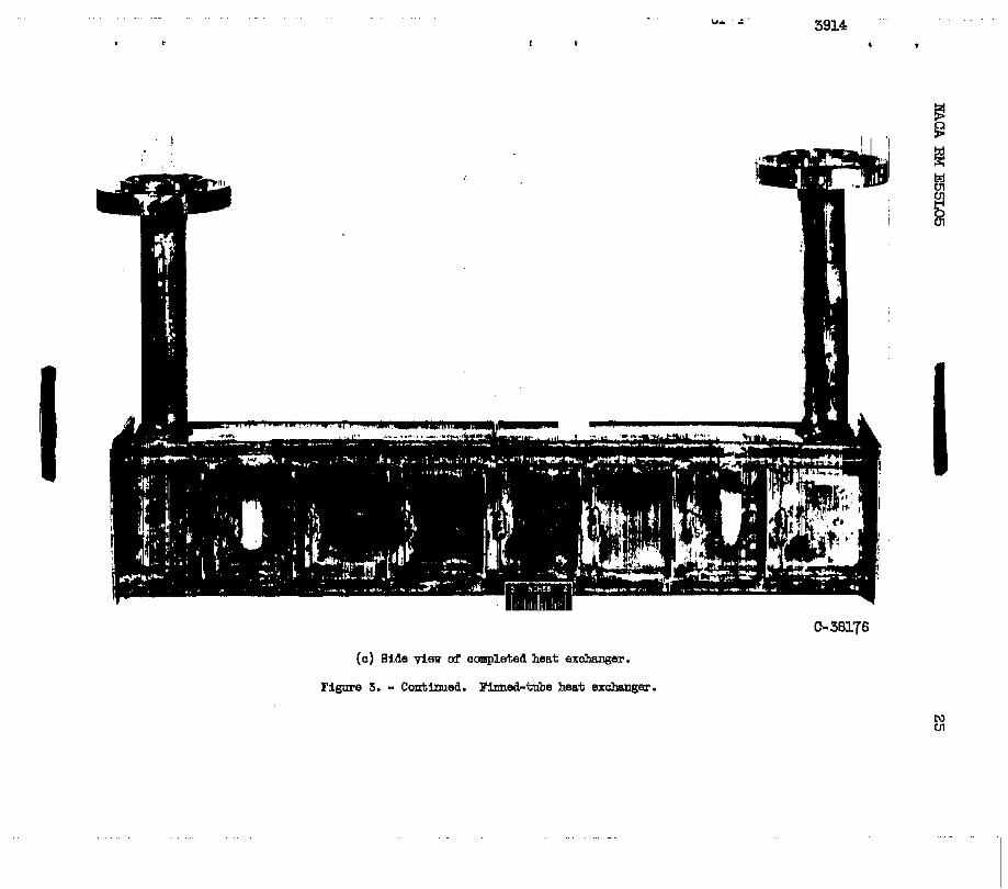
Finned-tube heat exchanger. - The finned-tube heat exchanger i s shown i n figure 3. Sodium flows through 102 3/16-inch outside diameter tubes, which have 0.016-inch w a l l s , arranged t o form a two-pass crossflow heat exchanger. The tubes are i n a skaggered array with three tubes i n each bank and a half round against the exchanger w a l l . Plates, 0.020 inch thick and 28 inches long, w e r e drilled, dimpled, and press f i t t ed Over the.102 tubes. There are 77 f i n s giving a spacing between f ine of about 0.032 inch. The sides and header are made of a 1/8-inch plate . A l l components are made of AIS1 300-series s ta in less steel. This ex- changer was also thoroughly tes ted for leaks.
Pressure-drop data were taken with and without heat addition. For the isothermal conditions, the air-flow rate is set and preheated t o a desired tenperatwe level. After equilibrium is reached, flow rate, pressures, and temperatures are recorded. The flow rate is varied from 0.5 t o 3 pounds per second for a range of exchanger-inlet-& tempera- tures frm 70° t o 600' F.
The following general procedure is used to obtain experimental data with heat transfer. Using the preheaters, the entire sodium loop is heated t o about 3000 F with the exception of the sump tank whlch is brought up t o 650° F. Heating the s&um t o this higher temperature as- 0
sure8 f l a r through cold areas such 88 the flanges which are not preheated. A i r - f l o w rate and temperature are se t . The sodium pump i s started and i t s speed is adjusted to give a flow of about 5 pounds per second. The -
NACA RM E55L05 n
7
main heater power supply is turned on t o b r i n g the sodium temperature t o above 800' F. The e l e c t r i c power i s then adjusted t o balance the heat t ransfer red to the air and surroundings. After equilibrium conditions are obtained, power input, flaw rates, pressures, and temperatures axe recorded.
c
The air-flow rate is changed in suitable increments ranging from 0.5 t o 3 pounds per second for exchanger-inlet-air temperature from 70° to 600° F. Sod ium temperature varied from 800° t o about llOOo F.
METHOD OF CALCULATION
Heat-Transfer Coefficient
I ( A l l synibols used herein are def ined in appendix A. 1 The calculated heat transferred to the air averaged 8 percent dove the heat given up by the sodium. Since the heat transferred cannot exceed the heat given up, the sodium heat loss was used in calculating average heat-transfer coefficients.
The log mean-temperature d i f f e ren t i a l 8, was calculated from the difference in sodium and air temperature at the i n l e t and out le t of the heat exchanger.
81 - 02
01 *2
e, = I n -
The inside tube" temperature w a s a s s m d to be equal to the sodium temperature. For the condition of the highest heat flux available, cal- culations showed that the temperature drop through the sodium film and tube w a l l would be i n the order of 2O P, therefore, the error introduced would be negligible.
The physical properties of air, specif ic heat cp and viscosi ty p, L were obtained from reference 1. A thermal conductivity k, tha t var ies
as the square root of the absolute temperature (ref. 2) was used. All
bers were evaluated at an average film temperature Tf. The following - properties of air used in ca lcu la t ing Nusselt, PrGdt l , and Reynolds num-

8 - equation was used to def ine an average film temperature
NACA RM E55L05
Friction Factor
Shell-and-tube heat exchanger. - A diagram representing the air side of the shell-and-tube heat exchanger sharing the s ta t ions used I n cal- culating pressure follows: 3 m
M
Heat exchanger
-. A i r f e
I' I l
Stations 0 x 1 2 3 - All instruntentation, consisting of t o t a l kenperature, t o t a l pressure, and static pressure was located at positions 0 and 3.
The fr ic t ion pressure drop, from sta t ion 1 t o 2, w a s obtained from the experimental data by subtracting the momentum preseure drop from the s t a t i c pressure drop.
G1 nPfr = (P, - P,) - - g cv2 - v,)
where tl and t,2 are absolute static temperatures at s ta t ions 1 and 2. Static pressures p1 and . p2 were calculated from recorded data taken at s ta t ions 0 and 3 by the following procedure:
Entrance losses: Because the Mach numbers a t the i n l e t were less than 0.5, Bernoulli'.s equation was applied for the re la t ion of t o t a l to stat ic pressure in order t o determine the stat ic pressure at s ta t ion 1.
P = p + pv2/2g (1)

NACA RM E55LO5 c
- 9
The kinetic-energy t e r m can be wr i t ten in terms of temperature, pressure, and welght flow. Rewriting equation (1) yields
G2Rt P = p + - 2gP
Static temgerature may be evaluated from the following equation which was obtained from the general energy equation for a perfect gas.
(3 1
Substi tuting the expression for t of equation (3) into equation (2) and applying the assumption that the to ta l p ressure and t o t a l temperature remain constant from station 0 t o 1, the following equation was used t o determine the static pressure after the contraction:
The vena contracta losses me taken as a factor C, times the aver-
2
age velocity head at the entrance.
APvc = C,Gx/2gp, (5 1 where C, is a function of the free flow fract ion of the heat exchanger and values are given in reference 3.
\ Subtracting equation (5) from (4) gives the s ta t ic pressure at sta- t i on 1.
P1 = P, - APvc
Bit regain: The momentum change across the sudden expansion be- tween s ta t ions 2 and 3 can be wri t ten as follows:

10 - NACA RM E 5 W 5 . Applying equation (3) i n conjunction with equation (61, the following re la t ion for s ta t ic p ressure p2 is obtained i n term of measured quan- tities of position 3.
Total temperature T2 WM assumed t o m
* m r(
tQ be equal t o t o t a l temperature
me average f r i c t i o n factor f /2 -was calculated f r o m the fric- tion pressure drop by use of the conventional relation modified t o a
where
solving for ff 2
f f = f - Tf rb
where
Finned-tube heat exchanger. - The pressure-drop data for the finned- tube heat exchanger were calculated from equations developed for the shel l - and-tube heat exchanger. The pressure and temperature at the centerline of the first row of tubes were calculated i n two steps. Equation (4) waa applied for the contraction due t o the f i n s and then for the contrac- t ion at the tubes. Vena contracts loss due t o the. f i n s m a accounted for. Outlet conditions at the laat row of tube6 were also calculated i n two steps applying equation (7) for each expansion.
"
..

NACA RM E55LO5 z
RFSuI;TS AND DISCUSSION
Shell-and-Tube Heat Exchanger
11
Data f o r the shell-and-tube heat exchanger were obtained for two degrees d sodium purity. The oxygen content of the sodium had a marked ef fec t on the heat-exchanger heat-transfer characteristics.
ol Heat balance. - A heat balance for the rum with filtered sodium is
G. co shown in f i gu re 4 where the heat given up by the sodium Qa i s plot ted
against the heat transferred t o the air Qa. A 45O l i n e is dram t o represent the ideal heat balance. The plot s h m that the calculated hea t t ransfer red to the air exceeded the heat given up. The average de- viat ion from the ideal l i n e is about 8 percent. z
d N
Heat-transfer coefficient. - Heat-transfer coefficients were taken for two conditions of sdium purity. The f i rs t set w a s obtained for so-
3 diu having an oxygen content-in excess of 0.50 percent and a second set .I of runs.representing data f o r sodium having less than 0.02 percent
oxygen.
1 A i r heat-transfer data f o r sodium of relatively high oxygen content are presented i n figure 5(a). The results m e shown with the Nusselt nuniber divided by the Prandt l nuniber raised t o t h e 0.4 parer Nq/(Prf)*'* plotted against a . d i f i e d Reynolds n-er pfVbD/+. The s o l i d l i n e represents the conventional single-tube correlathm corrected for the L/D r a t i o (ref. 4) .
The L/D r a t i o f o r the exchanger w a s 180 and therefore the equation can be reduced t o
NU = 0.0216 Pr 0.4 Re0.8
For inlet-air temperatures of less than 3000 F the data f e l l off to horizontal l ines with increasing Reynolds number. A similar trend may be noted for the higher inlet-air temperature. A t the highest Repol& nunibers the data i s beginning t o f a l l away from the so l id l ine . In order t o determine the cause of this drop off i n the heat-transf er cceff icient, a sodium sampling unit , as described i n reference 5 w8s employed. A sample of sodium taken from the sump tank showed that there was a rela- t i v e l y large amount of oxygen i n the system.

12 - NACA RM E55La5
Because the heat exchanger is one of the coldest components ip the loop, it effect ively becomes a cold trap, S & b oxide precipi ta tes out and co l l ec t s i n dead ereas- of the she l l and therefore part of the heat- t ransfer area becornes ineffective. The higher the air flow the mre oxide col lects and fur ther reduces the heat-transfer area with the re- sul tant l o w heat-transfer coefficients.
The oxygen content w a s reduced from 0.50 t o 0.02 percent by paselng sodium through a 5-micron micrometallic filter. Additional heat-transfer runs w e r e taken and the results are shown i n figure 5 (b) . The data taken wi th f i l t e red sodium agreed well with the recommended correlation and there was no leveling off of the heat-transfer coefficient for low i n l e t - air temperature. I f t he sodium is r e l a t ive ly f r ee of m e n the heat- t ransfer performance of a shell-and-tube heat exchanger can thus readily be predicted.
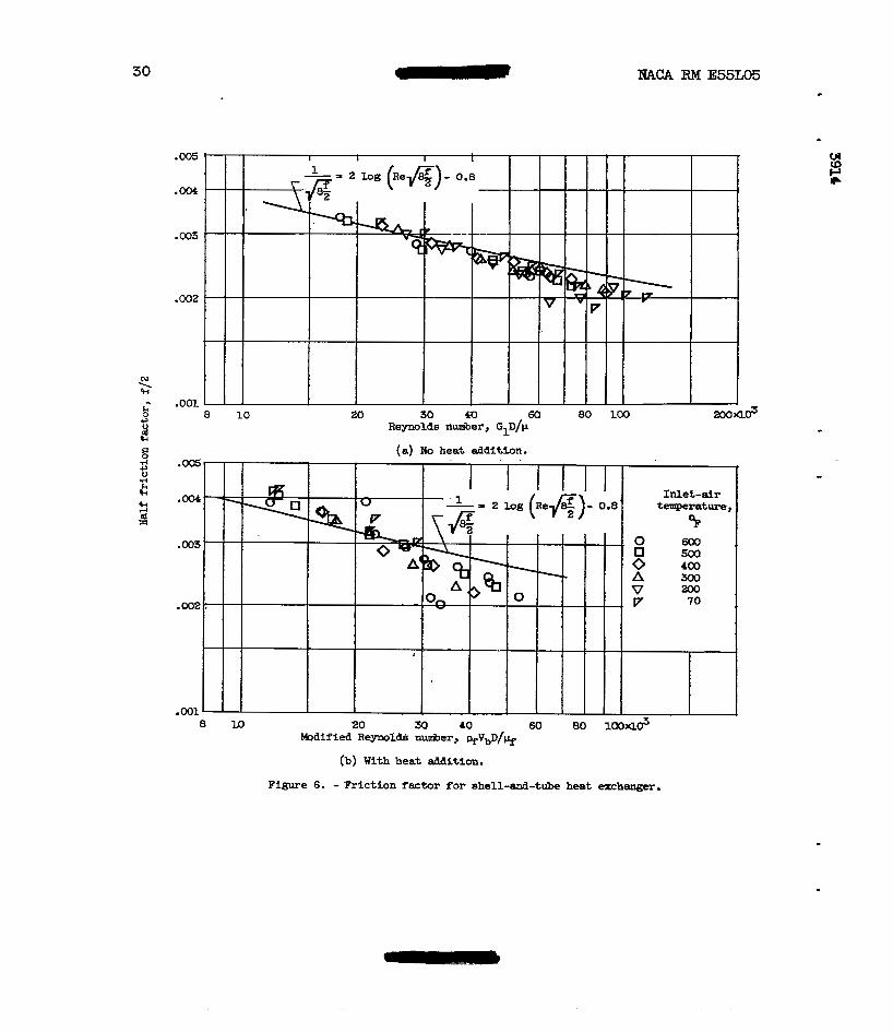
Friction-factor data. - The experimental friction-factor data with no heat addition for the shell-and-tube heat exchanger is shown i n f lg- ure 6(a). H a l f f r i c t ion f ac to r f f / 2 is plotted against the Reynolds number GID/p. Included for comparison is the &m&-Nikuradse curve for the re la t ion between f r i c t i o n factcor and Reynolds nurnber which is
. . . . .
= 2 log (Re G)- 0.8
The data agree with the recommended K&dn-Nikuradse l i ne for the Reynolds nunibem covered.
Friction-factor data taken with heat transfer is shown in f igure 6(b) . The data are also coqared with the solid l ine representing the above equation. H a l f f r i c t ion f ac to r Fe plotted against a modified Rey- nolds nmiber where all properties of air are evaluated at the f i lm t&- perature. The data for Reynolds nUber6 greater than 30,000 lie about 10 t o 20 percent below the sol id line. The reason for this discrepancy cannot be explained. It should be noted that t h i s area represents data of high ex i t Mach number and i n some cases high heat flux.
Finned-Tube Heat Exchanger Friction Factor
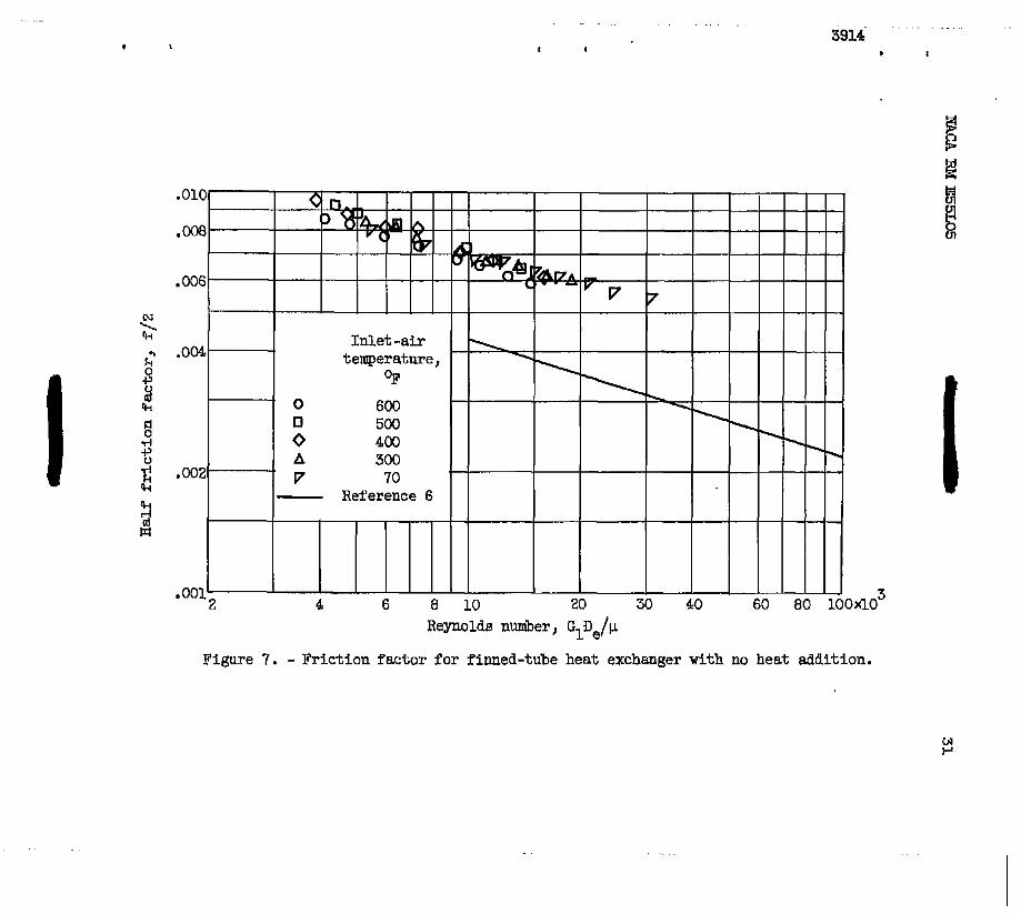
Because of weld f a i lu re s pressure-drop data for the finned-tube heat exchanger is limited to isothermal runs. Figure 7 shows the f r ic t ion- factor. data for f5v.e i n l e t - a i r .temperatures. The aspect r a t i o of each passage is about 100 and L/De i s about 440. The data of this irrvesti- gation is compared with an analytical investigation (ref. 6) for flow be- tween parallel plates. The experimental data f a l l about 55 percent above the Eolid line representing f / Z f o r parallel plates. The difference
.
c
. .
L

NACA RM E55LO5 I
13
in the experimental data and the so l id l i ne i s appsrently due t o t h e interference effect of the tubes. A description of the failure of t h i s heat exchanger and its possible cause is included i n appendix B.
.)
SUMMARY OF RESULTS
Heat-transfer and pressure-drop data were experimentally obtained w for the air s ide of a liquid-metal t o air shell-and-tube heat exchanger. P (D
tP Because of veld fa i lures , data f o r a f inned-tube exchanger were limited t o isothermal pressure drop. The in le t -a i r temperature w a s varied from
- 70° t o 60O0 F over a Reynolds n-er range of 7000 t o 115,000. The 80-
dium temperature ranged from WOO t o UOOO F. The fouowing results were obtained:
1. Air-side heat-transfer coefficients with f i l t e r e d sodium cor- related with conventional single-tube heat-transfer coefficients.
2. Because of oxide precipi ta t ion air-side heat-transfer data with . sodium of high oxygen content f e l l below the r ecomnded l i ne fo r t he lower i n l e t -air temperatme. -
3. Isothermal air-side frict/io?-factor data fo r the shell-and-tube heat exchanger agreed with the Karman-Nikuradse curve.
4. Air-side fr ic t ion-factor data with heat transfer on the she l l - and-tube heat exchanger f e l l about 10 t o 20 percent below the recommended l ine at high Reynolds nunibers but agree reasonably w e l l at low Reynolds Llumbers.
5. The finned-tube isothermal air-side f r i c t i o n factor w a s 55 per- cent higher than theory predicts for f lat plates which is probably due t o tube interference.
Lewis Flight Propulsion Laboratory National Advisory C o d t t e e for Aeronautics
Cleveland, Ohio, Deceniber 8, 1955
14
APPENDM A
NACA RM E55I105
A
cC
C P D
De
F
f
G
Q
h
k
L
Nu
P
Pr
P
m v c
Qa
%a
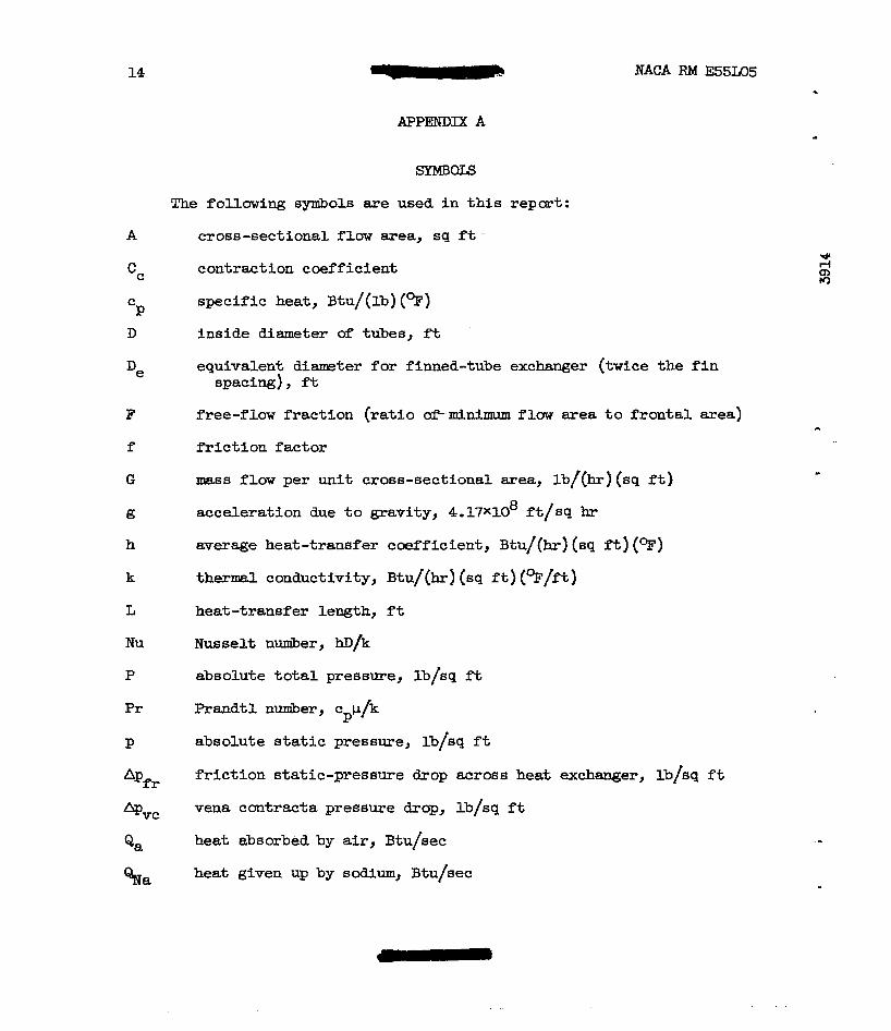
SYMBQLS
The following synibols are used i n t h i s repart:
cross-sectional flow area, sq ft -
contraction coefficient
specif ic heat, Btu/(lb) (9)
inside diameter & tubes, f t
equivalent diameter for finned-tube exchanger (twice t h e f i n spacing), f t
free-flow f rac t ion ( ra t io ~ f m i n i m u m flow area t o f ron ta l area)
f r i c t ion f ac to r
mass flow per unit cross-sectional ares, lb/(hr)(sq f t )
acceleration due t o gravity, 4.17X108 ft/sq hr
average heat-transfer coefficient, Btu/(hr) (sq f t ) (OF)
thermal conductivity, Btu/(hr) (sq f t ) (%/ft)
heat -transfer length, f t
Nusselt number, hD/k
absolute total pressure, lb/sq ft
Prandtl nuniber, cPp/k
absolute static pressure, lb/sq f t
f r ic t ion s ta t ic-pressure drop am068 heat exchanger, lb/sq f t
vena contracta pressure drop, lb/sq ft
heat absorbed by air, Btu/sec
heat given up by sodium, 3tu/sec
U

NACA RM E55L05 15 - R
Re
S
T
-
LE1 CD 5 3 G
Tf
Ts
t
V
w ,.
r "
6
P
P
gas constant for a i r , 53.3 ft-lb/(lb) (%>
Reynolds nuiber, pVD/p, GD/p
heat-transfer area, sq f t
t o t a l temperature, 91
average bulk temperature defined as (T1 + T2)/2, ?R
average film temperature defined as (Ts + Tb)/2, ?Fi
average inside surface temperature defined as the average sodium temperature, OR
s t a t i c temperature, 92
velocity, f t /hr
r a t e of flaw, lb/hr
r a t i o of specific heats of a i r
temperature difference between air and sodium, %
log mean temperature difference, qi
absolute viscosity of a i r , lb/(hr) ( f t )
density, lb/cu f t
Subscripts :
a a i r
av average
b bulk (when applied t o properties, indicates evaluation at bulk temperature Tb>
f f i lm (when applied t o properties, indicates evaluation at average film temperature Tf 1
N a SOdiUm
X station before vena contracta -
- 0 s ta t ion ahead of heat exchanger
"-

16 - NACA RM E55L05
1 station at exchanger i n l e t
2 stat ion at exchanger outlet
3 s ta t ion af'ter heat exchanger

NACA RM E55L05 - 17
The finned-tube heat exchanger was thoroughly checked fo r leaks as described i n the text . The exchanger wa8 i n s t a l l ed and isothermal air- side f r i c t i o n factor data w e r e taken. After the initial runs w e r e com- pleted, sodium w a s circulated through the system t o obtain data with heat addition. After only a few minutes of sodium flaw the leak-detector a l a r m went off and shut d m the system. The test section w a s r e m e d and cleaned and a pressure check with a i r and water shared that 13 tubes leaked severely with only 5 pounds per square inch air pressure. The exchanger was sectioned and examined.
I n order t o understand m r e fully the method and came of fa i lure , the nethod of construction mupt be ham. The two header plates and 77 f i n s were alinement plates as -
stacked and drilled as a uni t i n arder t o elimfnate any mis- of holes. T h e tubes w e r e hel iarc w e l d e d i n t o one of the header shown in the sketch below.
Eeliarc w e l d
Before welding After w e l d i n g
The f i n s were dimpled t o provide spacing and pressed Over the tubes. The other header pla te was then w e l d e d and the other pieces of the ex- changer were assenibled.
after fa i lure , the header cover plates w e r e cut off exposing the ends of the tubes. The first obvious f a u l t ‘ ~ a 8 that the tubes ne= each end were bowed outward toward the ends w h i l e the tubes near the center had r-ned straight. One of the b d d t&es is s h m i n figure 8(a). The end tubes were also bent sharply at the inner edge of the header plates as sham i n figure 8. Close examination of f igure 8(b) shows tha t
- actual fa i lu re occurred at the junction of the helitarc weld and the tube.

18 NACA RM E55L05
The one-piece f i n s apparently were the main factor contributlng t o the failure. The failure was probably caused by the rapid heating of the h.
fins relative t o the header plates which buwed the tubes and simultan- eously d r e w the tubes from the headers. An unexplained fact is that the f i n s remained elongated relative t o the header plates after cooUng. This may be due t o the relief of in te rna l stresses i n t h e f i n s from the dimpling process.
1. Keenan, Joseph H., and Kaye, Joseph: Thermodynamic Propertiee of A i r . John Wiley & Sons, Inc., 1945.
2. Humble, Leroy V., Lowdermilk, Warren E., and Desmon, Leland G.: Meas- urements of Average Eeat-Transfernd Friction Factor Coefficients for Subsonic Flow of A i r i n Smooth Tubes at High Surface and Fluid Temperatures. NACA Rep. 1020, 1951. (Supersedes RACA R ” 8 E7L31, E8L03, E50E23 and ESOH23.1
3. McAdams, William H.: Heat Transmission. Second ed., M c G r a w - H i u Book Co., Inc . , 1942.
4 . Weiland, Walter F. , and Lowdermilk, Warren H. : Measuremute of Heat- Transfer and Frict ion Coefficients for Air F l m n g i n a Tube of Length-Diameter Ratio of 15 at High Surface Temperatures. NACA RM E53E04, 1953.
-
5. Lyon, Richard N., ed.: Liquid-Metals Hand5ook. Second ea., A t o m i c ”
Energy Comm. , Dept. Navy, June 1952.
6. Deissler, Robert G.: Analysis of Turbulent H e a t Tranafer and Flow i n the Entrance Regions of Smooth Passagea. mAcA TN 3016, 1953.

I I
.. . CF-3 back . ..
I I 3914 i 1
Heat exchanger
I Pump an8 Variable sump tank epeed motor
.. .
. . . - - . . . . . . . . . . . . . . . . . . . . . . . .
1 N 0
7 4. I 5"
(a) cross section.
Figure 2. - Shell-and-tube heat axohanger.

NACA RM E55L05 21
(b) Side view of completed he& exchanger.
Figure 2. - Continued. Shell-and-tube heat exchanger. -

22
(c) End view &awing 241 tubes welded to header plate.
Figure 2. - Concluded. Shell-&-tube heat exchanger.

. . .. . . . . .. . . . . . .
I I I
I
0.020"
3914 .. .
6 I
n I 4.W'
3.28" bY
Pins; 28 102 Tubes; E 3 'Pubes an8 Bins are ilin
soaim flow 4
. . . .. .

. . . . . . . . . . . . . . . . . -. . . . . . . . . . . . . . . . . " . . . . . . . . . . . . . . . . . . - . . . . . . . - . . . . . . . . . . . . . . . . . . . . ..
!
c-34644
I
. . . . . . . . . . . . . . . . . . .. . . .. . . . . . . - . .
J
VT6€
. . . . . . . . 3914 " '
4 t
. . .
N cn
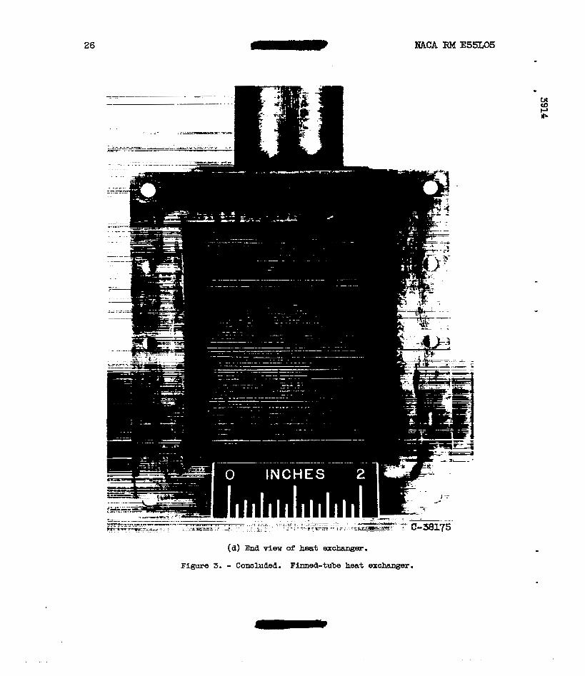
26
(a) End v iew of heat exchanger. Figure 3. - Concluded. Finned-tube heat =changer.

WCA RM E55L05 *
Heat given up by sodium, %a, Btu/sec
Figure 4. - Heat balance.
27

28
80
60
w n i O h 40
PI \ 5 &
30
I I 6 8 10 20 30
W b D I C l f
(a) Pr ior t o filtering of sodium.
Figure 5. - Heat-transfer data.

XACA RM E55IQ5
200
100
80
60
40
30
Y"
10
29
(b) With f i l t e r e d sodium.
Figure 5. - Concluded. Eeat-transfer data.
30
Reynolds number, GID/p
(a) No heat adaition.
(b) With heat addition.
Figure 6. - Friction factor for ehell-and-tube heat exchanger.
. .~ . . .
I 1 3914
. . . . . . . . . . . ..
* I
Reynolds number, GIDe/p
Figure 7. - Friction factor f o r finned-tube heat exchanger with m heat aaaition.
. ..

.. . . . . .
I
. . . . .
I I
. .. . . . . . .. . . . . . .. .
I
PT6€ ' .. . . .

NACA €U4 ESSLOS
- 33
(b) Tube-to-header joint. 3/16-Inch O.D. by 0.016-inch wall tube t o l/&inch header plates. (5X.)
Figure 8 . - Concluded. Section of fizmed-tube heat exchanger.
NACA - Langley Fleld, VI.
? I