aea pk-232 technical reference manual pk-232... · this pk-232 has been certified under the limits...
TRANSCRIPT

TECHNICAL REFERENCE MANUALMODEL PK-232 DATA CONTROLLER
ADVANCED ELECTRONICS APPLICATIONS, INC.
(Preliminary Release)

PK-232 TECHNICAL MANUAL
PK232TM Rev. A 5/87 i Page 2
PREFACE TO THE PK-232 TECHNICAL REFERENCE MANUAL
Please read this preface in its entirety. It contains information about how to receive warranty serv-ice from AEA, the current software installed in your PK-232 and AEA's software update policy. Thisinformation is important; if you do not read it, you may damage your unit.
RF Interference Information To User
This PK-232 has been certified under the limits for Class B computing devices under Subpart J ofPart 15 of the FCC rules, and is listed under FCC Identification Number DLX42690056.
This equipment generates and uses radio frequency energy. If it is not installed and used properly,that is, in strict accordance with AEA's instructions, it may cause interference to radio and TV re-ception. It has been type tested and has been found to comply with the limits of a Class B comput-ing device in accordance with the specifications in Subpart J of Part 15 of the FCC rules, which aredesigned to provide reasonable protection against such interference in a residential installation.However, there is no guarantee that interference will not occur in a particular installation. If thisequipment does cause interference to radio or TV reception, which can be determined by turningthe PK-232 on and off, the user is encouraged to try and correct the interference using one ormore of the following measures:
Reorient the antenna of the device receiving interference.Relocate the computer with respect to this device.Plug the computer into different outlet so the computer and the device are on different branchcircuits.
If necessary, the user should consult the dealer or an experienced Radio/TV technician for additio-nal suggestions. The user may find 'How to Identify and Resolve Radio-TV Interference Problems',a booklet prepared by the FCC, helpful.
USE SHIELDED CABLE FOR ALL RS-232 CONNECTIONS
As part of its continuing program of product improvement, AEA reserves the right to make changesin this product's specifications. Changes will be made periodically to the information in this docu-ment. These changes will be incorporated in new issues of this manual.
There may be technical in accuracies or typographical errors in this document. Please addresscomments and corrections to AEA Incorporated, PO Box C2160, Lynnwood, WA 98036-0918. AEAreserves the right to incorporate and issue any information thus supplied in whatever manner itdeems suitable without incurring and obligations whatever.
FIRST ISSUE - PRELIMINARY RELEASE (MAY 1987)I/A/W Software Release Date 21-Jan-87
PK-232 TECHNICAL MANUAL
PK232TM Rev. A 5/87 ii Page 3
INTRODUCTION
Your AEA PK-232 Data Controller is the connection between your computer and radios. The PK-232performs all of the control, modulation, demodulation, coding and encoding function required toestablish and maintain data and text communications between your station and any other suitably-equipped station, as well as other communication facilities equipped for digital communications.
The PK-232's packet system software is derived from and compatible with the original TAPR TNCsand presents many of the advanced features of that design, coupled with significant enhance-ments based on experience gained by thousands of TAPR-equipped amateur packet stations world-wide.
This manual is your reference guide to the technical aspects of the PK-232, its maintenance andrepair, as well as special software information for programmers and applications developers in digi-tal Amateur Radio.
BATTERY BACK-UP
Your PK-232 uses batteries to back up the user-programmable values in the system. If you don'tinstall batteries, you'll have to re-enter all of your personal system settings each time you turn onthe PK-232. Your PK-232 will operate normally in all modes but will not retain your personalized pa-rameters such as your call sign, until you install three AA-size batteries in the battery holder insidethe chassis cover. We recommend that you choose alkaline batteries for this application.
Remove the four screws from the sides and the two screws from the rear of the chassis. thenlift off the PK-232's cover. Take care not to disturb the black or red wires that attach the bat-tery holder to the printed circuit board.
Find the positive and negative symbols embossed on the inside of the battery holder. Inserteach battery, carefully matching the positive symbols on the battery with the positive symbolson the holder.
Replace the cover and the six screws.
The battery back-up retains all the parameters except the time-of-day clock and the MHEARD(Monitor Heard) list. These two functions are controlled by the microprocessor.

PK-232 TECHNICAL MANUAL
PK232TM Rev. A 5/87 TOC-1 Page 4
TABLE OF CONTENTS
CHAPTER 1 – INTRODUCTION
Paragraph Page
1.1 Introduction ..................................................................................... 1-1 71.2 Scope .............................................................................................. 1-1 71.3 General Description ........................................................................... 1-1 71.4 Specifications .................................................................................... 1-1 71.4.1 Operating Modes .................................................................... 1-2 81.4.2 Modem Characteristics ............................................................ 1-2 81.4.3 Processor System ................................................................... 1-2 81.4.4 Input/Output Connections ....................................................... 1-2 81.4.5 Controls and Indicators ........................................................... 1-3 91.4.6 General ................................................................................. 1-3 9
CHAPTER 2 – FUNCTIONAL DESCRIPTION
2.1 Major Sections .................................................................................. 2-1 102.1.1 Analog Section ....................................................................... 2-1 102.1.2 Digital Section ........................................................................ 2-1 102.1.3 Input/Output Section .............................................................. 2-1 102.1.4 Display Section ....................................................................... 2-1 102.1.5 Power Distribution .................................................................. 2-1 10
CHAPTER 3 – THEORY OF OPERATION
3.1 System Diagrams .............................................................................. 3-1 113.1.1 Block Diagrams ...................................................................... 3-1 113.1.2 Logic Diagrams ...................................................................... 3-1 113.1.3 Schematic Diagrams ............................................................... 3-1 113.2 Analog Subsystem ............................................................................. 3-2 123.2.1 Receive Function .................................................................... 3-2 123.2.1.1 Receive Circuits ........................................................... 3-2 123.2.2 Transmit Function ................................................................... 3-3 133.2.2.1 Transmit Circuits .......................................................... 3-3 133.3 Digital Subsystem ............................................................................. 3-3 133.3.1 Z80A Central Processing Unit ................................................... 3-3 133.3.2 Memory ................................................................................. 3-4 143.3.3 8536 CIO Counter/Timer and Parallel I/O Unit .......................... 3-4 143.3.4 8530 SCC Serial Communications Controller .............................. 3-6 16

PK-232 TECHNICAL MANUAL
PK232TM Rev. A 5/87 TOC-2 Page 5
CHAPTER 4 – HOST MODE AND SPECIAL APPLICATIONS
Paragraph Page
4.1 Introduction to Host Mode ................................................................. 4-1 184.1.1 Why Do We Need a Host Mode ................................................ 4-1 184.1.2 How does Host Mode Help Us? ................................................ 4-1 184.1.3 Entering Host Mode ................................................................ 4-2 194.1.4 Leaving Host Mode ................................................................. 4-2 194.1.5 The Host Mode Dialog ............................................................. 4-2 194.1.6 Host Mode Recovery ............................................................. 4-3 204.2 Host Computer Commands ................................................................ 4-3 204.2.1 Unsupported Commands ......................................................... 4-4 214.2.2 Host Mode Mnemonic Indicators .............................................. 4-4 214.2.3 CONNECT and DISCONNECT ................................................... 4-5 224.2.4 ON/OFF Booleans or Switches ................................................. 4-5 224.2.5 TXDELAY ............................................................................... 4-5 224.2.6 SENDPAC ............................................................................... 4-5 224.2.7 Interrogation or Query Commands ........................................... 4-5 224.3 PK-232 Responses ............................................................................. 4-5 224.3.1 Responses to Interrogation or Query Commands ....................... 4-6 234.3.2 OPMODE Response ................................................................. 4-7 244.3.3 Link Status Request Response ................................................. 4-7 244.3.4 Call Sign Formats ................................................................... 4-7 244.4 Sending Data to the PK-232 ............................................................... 4-8 254.4.1 Data Polling ........................................................................... 4-8 254.4.2 The HPOLL Command ............................................................. 4-8 254.4.3 Special Case in AMTOR ........................................................... 4-9 264.4.4 Link Messages ........................................................................ 4-9 264.5 Host Mode and Special Packet Applications ......................................... 4-9 264.6 Raw HDLC ........................................................................................ 4-9 264.7 "KISS" TNC Asynchronous Packet Protocol .......................................... 4-10 274.7.1 Starting "KISS" TNC Operation ................................................ 4-11 284.7.2 "KISS" TNC Special Characters ................................................. 4-11 284.7.3 "KISS" TNC Frame Structure .................................................... 4-11 284.7.4 "KISS" TNC Commends ........................................................... 4-11 284.7.4.1 TXDELAY: CTL = $01 .................................................... 4-11 284.7.4.2 PERSISTENCE: CTL = $02 ............................................ 4-12 294.7.4.3 SLOTTIME: CTL = $03 .................................................. 4-12 294.7.4.4 TXTAIL: CTL = $04 ...................................................... 4-12 294.7.4.5 FULLDUP: CTL = $05 ................................................... 4-13 304.7.4.6 HOST OFF: CTL = $FF .................................................. 4-13 304.7.4.7 DATA: CTL = $00 ......................................................... 4-13 304.8 Maximum Block Size .......................................................................... 4-14 314.9 MEMORY, I/O and ADDRESS Commands ............................................. 4-14 314.9.1 MEMORY Command ................................................................ 4-14 314.9.2 ADDRESS Command ............................................................... 4-14 314.9.3 I/O Command ........................................................................ 4-15 324.10 Converse and Transparent Modes ....................................................... 4-15 324.11 MHEARD Command in Host Mode ....................................................... 4-15 324.12 Software Release Date Code .............................................................. 4-16 334.13 Product Type Code ............................................................................ 4-16 33

PK-232 TECHNICAL MANUAL
PK232TM Rev. A 5/87 TOC-3 Page 6
CHAPTER 5 – MECHANICAL ASSEMBLY AND DIS ASSEMBLY
Paragraph Page
5.1 Cover Removal .................................................................................. 5-1 345.2 Circuit Board Removal ....................................................................... 5-5.3 Circuit Board Assembly ...................................................................... 5-2 355.4 Cover Assembly ................................................................................ 5-
CHAPTER 6 – ADJUSTMENTS
6.1 Preliminary Setup .............................................................................. 6-1 366.2 Calibration Procedure ........................................................................ 6-6.2.1 AFSK Generator (Transmit) Adjustments ................................... 6-2 376.2.2 Demodulator (Receive) Adjustments ........................................ 6-3 386.3 Functional Tests ................................................................................ 6-
CHAPTER 7 – TROUBLESHOOTING
7.1 Introduction ..................................................................................... 7-1 407.2 General Tests .................................................................................... 7-7.2.1 Power Supply ......................................................................... 7-7.2.2 Obvious Problems ................................................................... 7-2 417.2.3 Assembly Problems ................................................................. 7-7.2.4 Cabling Problems .................................................................... 7-7.3 Specific Symptoms ............................................................................ 7-7.3.1 Symptom: Controller appears dead .......................................... 7-7.3.2 Symptom: Modem cannot be calibrated .................................... 7-4 437.3.3 Symptom: Transmitter cannot be keyed ................................... 7-7.3.4 Symptom: Transmitter signals not copyable by other stations ..... 7-7.3.5 Symptom: Received signals not copyable .................................. 7-7.4 Terminal Interface Troubleshooting ..................................................... 7-5 447.4.1 Symptom: Controller does not communicate with the terminal .... 7-7.4.2 Symptom: Controller signs on with mutilated data ..................... 7-7.4.3 Symptom: Controller does not respond or accept commands ..... 7-6 45
APPENDIX A – AX.25 LEVEL 2 PROTOCOL ..................................................... A 46
APPENDIX B – "KISS" TNC SPECIFICATION ................................................... B 70
APPENDIX C – DRAWINGS ........................................................................... C 75
APPENDIX D – WAVEFFORMS ....................................................................... D 83
Last Page 101

PK-232 TECHNICAL MANUAL CHAPTER 1 – INTRODUCTION
PK232TM Rev. A 5/87 1-1 Page 7
CHAPTER 1 – INTRODUCTION
1.1 Introduction
This Technical Reference Manual will assist you to maintain, repair and adjust your PK-232Data Controller. Please use this manual in conjunction with AEA's Operating Manual for thePK-232, Revision D.
The PK-232 Operating Manual contains complete and detailed information on controller op-erating procedures, controller commands and syntax, general installation methods, terminaland radio connections, as well as connector wiring diagrams, printed circuit board sche-matics, board layout drawings and parts list.
1.2 Scope
This manual includes information on theory of operation, hardware descriptions and trouble-shooting instructions and charts. In addition, detailed information on the PK-232's Hostmode is presented for the benefit of programmers and software application developers.
1.3 General Description
AEA's Model PK-232 is a multi-mode protocol converter and data controller that includesself-contained modems for all modes.
The PK-232 sends and receives Morse Baudot and ASCII RTTY, facsimile, AMTOR/SITOR andAX.25 packet. The PK-232 converts these signals to ASCII data end sends the data to yourterminal via an EIA standard RS-232 (CCITT V.24/V.28) serial port, and to your printer via aspecial Centronics-type parallel interface. Except for the printer interface, the reverse proce-dures convert ASCII data typed at your terminal to the signals and protocols required fortransmission to other stations.
All necessary tone generation and demodulation (modem) functions are built in; however,external modems can be connected to the PK-232 via dedicated rear-panel connectors. Alldecoding, encoding, protocol and transmitter control routines are stored in the PK-232'sfirmware in PROM and internal program memory.
Operating modes, speeds, modem tone pairs, filter bandwidths and system protocols are se-lected by typing commands on your computer or data terminal. Any communications or ter-minal emulator normally used with a telephone line modem can be used with the PK-232.
1.4 Specifications
As part of its program of product improvement, AEA reserves the right to make changes inthis product's specifications. Changes will be made to the information in this document andincorporated in revisions to this manual. Specifications are subject to change without notice.
1.4.1 Operating Modes
The PK-232 provides operation in Morse, Baudot, ASCII, AMTOR/SITOR, half- or full-du-plex Packet Radio in accordance with AX.25 protocols, facsimile, SIAM and Host and"KISS" TNC modes for use with packet protocols other than AX.25.

PK-232 TECHNICAL MANUAL CHAPTER 1 – INTRODUCTION
PK232TM Rev. A 5/87 1-2 Page 8
1.4.2 Modem Characteristics
Demodulator: Limiter-discriminator type, preceded by an eight-poleChebyshev 0.5 dB ripple bandpass filter
Receive bandpass: Automatically switched by operating modeVHF packet: Center frequency 1700 Hz, bandwidth 2600 HzHF (except CW): Center frequency 2210 Hz, bandwidth 450 HzCW: Center frequency 800 Hz, bandwidth 200 Hz
Modulator: Low-distortion AFSK sine wave function generator,phase-continuous AFSK
Output Level: 5 to 100 millivolts RMS, adjustable by rear-panel con-trol
1.4.3 Processor System
Protocol conversion: Zilog Z-80 microprocessorRAM: 16 kilobytesROM: Up to 48 kilobytes of ROM may be usedHardware HDLC: Zilog 8530 SCC
1.4.4 Input/Output Connections
Radio Interface: Two five-pin TTL connectors, selectable on the frontpanel
Input/output Lines: Receive audioTransmit audioPush-To-Talk (PTT)External squelch inputGround
External modem connector Five-pin TTL - TXD, RXD, DCD, PTT, GroundDirect FSK Outputs Normal and reverseOscilloscope Outputs Mark (Stop) and Space (Start)CW keying Outputs Positive: +100 VDC max. at up to 100 mA
Negative: -30 VDC max. at up to 20 mATerminal Interface: RS-232C 25-pin DB25 connector Input/Output RS-232 with full hardware and software handshake on
wires 1-8 and 20Terminal Data Rates Auto-baud selection of 300, 1200, 2400, 4800 and
9600 BPS. TBAUD adds 110, 150, 200 and 600 BPS.
PK-232 TECHNICAL MANUAL CHAPTER 1 – INTRODUCTION
PK232TM Rev. A 5/87 1-3 Page 9
1.4.5 Controls and Indicators
Front Panel Controls: Power SwitchRadio Selector SwitchThreshold Adjust
Indicators: Ten-segment discriminator-type bargraph indicator forHF tuning.DCD LED (Data Carrier Detect)
Status and Mode Indicators: Mode Group Status GroupBAUDOT STBYASCII PHASEPKT IDLEMORSE ERROR/CONVCHECK OVERFEC TFC/TRANSARQ RQ/CMDMODE L CONSTBY STA
MULTSEND
1.4.6 General
Power Requirements: +13 VDC (12 to 16 VDC) at 700 mAMechanical: Overall 11" × 8.25" × 2.5" (279.4 × 209.6 × 63.5 mm)
Weight 3 pounds (1.36 kilograms)

PK-232 TECHNICAL MANUAL CHAPTER 2 – FUNCTIONAL DESCRIPTION
PK232TM Rev. A 5/87 2-1 Page 10
CHAPTER 2 – FUNCTIONAL DESCRIPTION
2.1 Major Sections
The PK-232 Data Controller has five major functional blocks:
o Analog o Displayo Digital o Power Distributiono Input/Output (I/O)
Each of these functional blocks has its own distinct functions. The following paragraphs de-scribe each section.
Refer to the PK-232 Functional Block Diagram, Figure 1 in Appendix C, while reading thesedescriptions.
2.1.1 Analog Section
The analog section consists of active filters, limiters, a threshold detector, DCD (Data Car-rier Detect and diode discriminator circuits. Analog switches automatically adjust variouscircuit characteristics for each operating mode.
2.1.2 Digital Section
The digital section contains a microprocessor, read only memory (ROM) random accessmemory (RAM), two crystal-controlled clock generators an a variety of "glue" chips togate and isolate the digital signals.
2.1.3 Input/Output Section
The I/O Section provides a standard serial data path in accordance with EIA RS-232-Cand CCITT Recommendations V.24/V.28, between the PK-232 and the associated com-puter or terminal.
The I/O section contains an HDLC (High-Level Data Link Control) translator; output driv-ers for AFSK tones, DC logic voltages for direct FSK transmitter keying, CW DC keying sig-nals, a watchdog timer and PTT (push-to-talk) switching voltages for the associated trans-mitter.
The I/O section also isolates input and output control signal buffers and provides circuitsfor connecting an external modem.
All control and communications to and from the PK-232 pass through the I/O section.
2.1.4 Display Section
The display section consists of a tuning indicator and its associated driver; status andmode indicators with their drivers and receivers; a DCD indicator and a threshold control.
2.1.5 Power Distribution Section
The Power distribution section contains voltage regulators, DC-to-DC converters for thePK-232's operating system and a battery system for backing up maintaining the datastored in RAM.
PK-232 TECHNICAL MANUAL CHAPTER 3 – THEORY OF OPERATION
PK232TM Rev. A 5/87 3-1 Page 11
CHAPTER 3 – THEORY OF OPERATION
3.1 System Diagrams
Please refer to APPENDIX C for the various diagrams used as reference in this chapter.
3.1.1 Block Diagrams
Refer to the Functional Block Diagram, Figure 1 in APPENDIX C. Dashed lines separate thefive sections of the PK-232. Each section will be described separately and is labeled as fol-lows:
o Analogo Digitalo Input/Output (I/O)o Displayo Power Distribution
3.1.2 Logic Diagrams
Refer to the Logic Diagram, Figure 2 in APPENDIX C. Figure 2 shows the digital logic por-tion of the PK-232 which includes:
o the microprocessoro Read Only Memory (ROM)o Random Access Memory (RAM)o clock and control logico part of the display logico the logic associated with the digital communications between the PK-
232 and the terminal.
The major portion of the power distribution section is also shown on this drawing.
3.1.3 Schematic Diagrams
Refer to the Schematic Diagram, Figure 3 in APPENDIX C. Figure 3 shows the analog por-tion of the PK-232, which includes:
o mode-dependant bandpass filterso MARK and SPACE resonatorso audio frequency discriminatoro mode-dependant low pass filtero comparator circuitryo AFSK generatoro watchdog timeo transmitter audio drivero keying circuitryo radio switchingo tuning indicator circuitry

PK-232 TECHNICAL MANUAL CHAPTER 3 – THEORY OF OPERATION
PK232TM Rev. A 5/87 3-2 Page 12
3.2 Analog Subsystem
Each of the PK-232's operating modes requires different bandwidths, as well as varyingAFSK tone and speed characteristics. The analog circuitry is adapted to these differences byusing program-controlled switches to place precision resistors in parallel with the fixed com-ponents of the circuits. In this manner, under software command, the analog circuits are op-timized for the mode selected.
3.2.1 Receive Function
Audio signals from the selected RADIO 1 or RADIO 2 input pass through a rolloff filter tocompensate for VHF receiver characteristics and are then applied to a buffer amplifier tolimit audio signal amplitude.
The signal then pass through a bandpass filter whose center frequency tuning and band-width are controlled by the OPMODE selection for optimum characteristics.
The bandwidth-limited signals pass through an amplitude limiter to remove variations inaudio levels. Mark and Space tones are separated in the Mark and Space resonators. Theseparated Mark and Space output signals are rectified in a diode discriminator circuit.
The detected data is filtered in an active lowpass filter and compared with a referencevoltage in a slicer circuit to digitize the data. The resulting data is then shaped and in-verted for passing to the internal modem circuitry.
When a full word of data (eight bits) has been assembled in the modem circuitry, an inter-rupt is generated to the microprocessor which then processes the data.
3.2.1.1 Receive Circuits
The received audio signals are routed through one of two radio connection receptacles,J4 (RADIO 1) or J6 (RADIO 2), or through the respective paralleled radio input cablejacks, J3 or J5. The radio is selected by SW2, the RADIO 1/RADIO 2 push-button switchon the front panel. Radio input and output connections are bypassed for RF by C64 andC63.
The audio input consists of resistor-capacitor combination R34 and C54 to compensatefor the audio characteristics of the average VHF FM radios by emphasizing higher-fre-quency tones and attenuating lower-frequency tones.
Input buffer amplifier U28-D limits received audio signal levels to prevent overloadingmultiple-resonator feedback-type 0.5-dB-ripple Chebyshev active bandpass filter formedby operational amplifiers U23 and U26.
Analog gates (FET switches) U22, U24, U25, U26 and U27 select filter center frequencyand bandwidth. Gate selection is a function of the operating mode.
Bandpass-filtered output signals are amplified and limited by U28-A to remove ampli-tude variations and passed to MARK and SPACE resonators U30 and U32. Gate U29 de-termines the tone-pair resonator tuning.
For CW signals, U31 transfers the bandpass filter output directly to the MARK channeldiscriminator. The SPACE channel is decoupled from the circuit and ignored.

PK-232 TECHNICAL MANUAL CHAPTER 3 – THEORY OF OPERATION
PK232TM Rev. A 5/87 3-3 Page 13
The tones processed by the resonators are rectified in a full-wave diode networkformed by D19 and D20 for the MARK channel, and D22 and D23 for the SPACE chan-nel. The MARK signal is positive with respect to the voltage reference (VR); the SPACEsignal is negative.
Output signals from both channels are envelope-detected simultaneously by a short andlong time-constant network and summed at the input of U32-B.
After passing through a lowpass filter to remove ripple, the signal is amplified by U32-C,U34-C and U34-D and then squared. Its logic level is shifted by a TTL inverter U15-C foruse by either an external modem or U6, a Zilog 8536 Counter/Timer and Parallel I/ODevice.
3.2.2 Transmit Function
Digital input signals from the terminal are received by the serial controller and passed tothe microprocessor for action. If ECHO has been commended ON, the input signals arerouted by the serial controller back to the terminal for display.
3.2.2.1 Transmit Circuits
Data to be transmitted is received over the RS-232 serial port and read by Z8530 SerialCommunications Controller U7 under the control of the Z80 microprocessor. The data isperiodically sent over the data bus to the Z8536, U6. The Z8536 translates the data intoa binary string at the correct data rate and routes the binary string to AFSK generatorU40.
The AFSK generator supplies one of two tones to selected RADIO connector J4 or J6,depending on the position of RADIO 1/Radio 2 switch SW2.
The transmit tone pair produced by the tone generator is selected by FET switch U35.This switch selects appropriate frequency-determining resistors R164, R165, R157 andR168, in accordance with the selected operating mode.
In addition, a logic level of five volts DC (5 VDC) or ground is presented at Scope/FSKreceptacle J7, either inverted or normal, for FSK transmitter keying.
At the same time that the generator is keyed, a Push-to-Talk (PTT) signal is supplied totransistor keyers (Q4 and Q5). The polarity of the keying signal is selected by jumpersJP2 and JP3 for the two radio receptacles.
This PTT signal is present as long as pulses from the timer in U7 refresh the timeout cir-cuitry of Q10 and Q3. If for any reason the program fails or becomes disabled, thetimeout circuitry prevents the PTT line from being activated.
3.3 Digital Subsystem
In the following discussion of the Digital Subsystem, the dollar sign ($) indicates hexadeci-mal numbers.
3.3.1 Z80A Central Processing Unit
The processor, U1, is a Z80A operating at 4.0 MHz. The peripheral chips U6 and U7 causesystem interrupts using the CPU's INT* input (pin 16). The NMI* and BUSRQ* inputs areunused, as are the RFSH, HALT and BUSAK outputs.

PK-232 TECHNICAL MANUAL CHAPTER 3 – THEORY OF OPERATION
PK232TM Rev. A 5/87 3-4 Page 14
3.3.2 Memory
The PK-232 memory consists of 48 kB of EPROM at U2 and U3, and 16 kB of static RAMat U4 and U5.
U2 is a 27256 EPROM which occupies the 32 kB address space between $0000 and$7FFF.
EPROM U3 is a 27128 occupying 16 kB from $8000 to $BFFF.
The read-write memory consists of two 6264 8 kB volatile static RAMs, U4 occupying$C000-DFFF and U5 at $E000-FFFF. Both U4 and U5 have their power backed up by bat-teries when the system power is off.
The 74LS139 address decoder at U10 receives address bits A13, A14 and A15 from theCPU, and provides chip enables for U3, U4 and U5. Address bit A15 is used directly as thechip enable for the U2 EPROM at address $0000.
U17 pin 8 provides a Memory Read (OE*) line for U2, U3, U4 and U5. U17 pin 11 is theMemory Write (·WE*) line for the RAMs U4 and U5.
3.3.3 8536 CIO Counter/Timer and Parallel I/O Unit
U6 is an 8536 CIO chip which provides 20 parallel I/O pins and three timers. This chip re-ceives address bits A0, A1 and A6 from the CPU. The PK-232's firmware addresses the8536 by forcing all other address bits high, yielding these addresses:
$BC - Parallel port A data$BD - Parallel port B data$BE - Parallel port C data$BF - Control port
The 8536 uses the CPU's 4.0 MHz clock on the PCLK input (pin 16). The 8536 interrupthas priority over the interrupt from the 8530 (U7).
Parallel port A controls several different functions in the PK-232:
Bit U6 Pin Function Sense Direction––––––––––––––––––––––––––––––––––––––––––––––––––––––PA7 26 Squelch InPA6 27 RTTY transmit data OutPA5 28 Wide shift enable Pos OutPA4 29 Tone enable Pos OutPA3 30 Calibration InPA2 31 FSK enable Pos OutPA1 32 CW key closed Neg OutPA0 33 Narrow shift enable Neg Out
PA3 counts the transition on the digital output of U40, the 2206 tone generator.
PA2 when high enables FSK for Packet and RTTY; when low PA2 enables CW. PA5, PA2and PA0 work together to determine the shift the PK-232 uses:

PK-232 TECHNICAL MANUAL CHAPTER 3 – THEORY OF OPERATION
PK232TM Rev. A 5/87 3-5 Page 15
PA5 PA2 PA0––––––––––––––– 0 1 0 Narrow shift FSK 1 1 1 Wide shift FSK 0 0 1 CW
Parallel port A can be controlled by the user directly. Set ADDRESS to $BF0D and thenread or write port A using the IO command.
Parallel port B pins PB4, PB5, PB6 and PB7 drive the Mode LEDs through the 7445 de-coder at U11:
PB7 PB6 PB5 PB4 LED––––––––––––––––––––– ––– 0 0 0 0 PKT 0 0 0 1 MORSE 0 0 1 0 ASCII 0 0 1 1 BAUDOT 0 1 0 0 CHECK 0 1 0 1 FEC 0 1 1 0 MODE L 0 1 1 1 ARQ 1 0 0 0 STBY 1 0 0 1 (FAX) 1 0 1 0 (SIGNAL or SIAM)
PB3 drives the SEND LED through one of the 7406 drivers at U18. Parallel port B pinsPB0, PB1 and PB2 drive the Status LED through the 7445 decoder at U12:
PB2 PB1 PB0 LED––––––––––––––– ––– 0 0 0 STBY 0 0 1 PHASE 0 1 0 OVER 0 1 1 IDLE 1 0 0 TFC TRANS 1 0 1 ERROR CONV 1 1 0 RQ CMD
Parallel Port C drive their functions through parts of the 7406 driver chip at U18:
PC0 STA LEDPC1 CON LEDPC2 MULT LEDPC3 Bar graph enable
When parallel ports B and C are used with the parallel printer, the pins are brought outfrom the 8536 unbuffered to the J2 connector:

PK-232 TECHNICAL MANUAL CHAPTER 3 – THEORY OF OPERATION
PK232TM Rev. A 5/87 3-6 Page 16
Bit U6 Pin J2 Pin Function Sense Direction––––––––––––––––––––––––––––––––––––––––––––––––––––––PB7 15 21 Data 8 Pos OutPB6 14 19 Data 7 Pos OutPB5 13 18 Data 6 Pos OutPB4 12 17 Data 5 Pos OutPB3 11 16 Data 4 Pos OutPB2 10 15 Data 3 Pos OutPB1 9 14 Data 2 Pos OutPB0 8 13 Data 1 Pos OutPC2 21 24 Busy Pos InPC1 20 23 Ack Neg InPC0 19 22 Strobe Neg Out
The Busy and ACK signals should each contain a 200-Ohm series resistor in the cable tothe parallel printer.
3.3.4 8530 SCC Serial Communications Controller
U7 is an 8530 SCC chip which provides two serial communications ports.
Port A is the HDLC port for Packet-Radio.Port B is the RS-232 interface to the terminal.
This chip receives address bits A0, A1 and A7 from the CPU. The PK-232 firmware ad-dresses the 8530 by forcing all other address bits high, yielding these addresses:
$7C - Terminal (Port B) control$7D - Terminal (Port B) data$7E - HDLC (Port A) control$7F - HDLC (Port A) data
The 8530 chip has a 2.4576 MHz clock that is totally independent of the rest of the sys-tem.
The serial interface signals TXD (J2 pin 2), RTS (4) and DTR (20) flow from the RS-232connector through the drivers on the 1489 chip at U19 to the 8530's RXDB, CTSB andDCDB pins respectively.
The 8530 output pins TXDB, RTSB and DTRB pins are buffered by the drivers on the 1488chip at U20 to the J2 pins RXD (3), CTS (5) and DCD (8) respectively.
Both the RTS (J2 pin 4) and DTR (pin 20) signals must be high for the 8530 to send dataon the RS-232 link.
J2 pin 8 (DCD) may be used as an active-high Packet Connect indicator for mailbox soft-ware. J2 pin 6 (DSR) is permanently pulled high. J2 pin 1 is frame ground and J2 pin 7 issignal ground. All other J2 pins are reserved for use with a parallel printer.
The SYNCB input (pin 29) is pulled high by R179. This input may be connected to a hard-ware EAS (Echo as Sent) switch to monitor the output in AMTOR, Morse, Baudot and AS-CII modes.
Forcing this pin low has the same effect as typing the command EAS ON.

PK-232 TECHNICAL MANUAL CHAPTER 3 – THEORY OF OPERATION
PK232TM Rev. A 5/87 3-7 Page 17
Port A interfaces with the modem. The RXDA and CTSA inputs are tied together so thatthe incoming data can be read either by the 8530's internal logic (for Packet mode) or bythe firmware directly on a bit-by-bit basis (for AMTOR, Baudot, ASCII and Morse modes).
Similarly, the TXDA output is tied to the 8536 PA6 output so that the outgoing data can becontrolled either by the 8530 or the firmware.
In HDLC operation for Packet mode reception, an internal phase-locked loop is driven by aclock that is 32 times the Packet baud rate.
The transmitter is driven by a clock right as the Packet baud rate. The divide-by-32 func-tion is performed by the 74LS393 at U8.
The U7 TRXCA output (pin 14) is the 32× clock, which may be used with an external mo-dem. This signal is connected to an input on U8, goes through 5 stages of divide-by-2 andis brought out out to the U7 RTXCA input (pin 12) as the 1× clock.
The RTSA output (pin 17) is the PTT signal, active low. For the PTT to remain active forany length of time, the DTRA output (pin 16) must furnish a constantly oscillating signal.This signal goes to the watchdog timer circuit.
Should the oscillating signal stop, the PTT will go inactive after a period determined bythe time constant of R146 (10 k) and C55 (47 µ).
For this scheme to work properly, the DTRA output is toggled every pass trough the mainloop of the PK-232 firmware.
In order to make the 8530 and 8536 chips operate with the Z80A CPU, a state machineconsisting of U9 (74LS164), U14 (74LS11) and U1 (74LS04) is used.
This circuit provides a Wait signal to the CPU and I/O Request and Interrupt Acknowledgesignals to the 8530 and 8536 at proper times, whenever the CPU begins an Interrupt Ac-knowledge cycle.
For more details, refer to the Z8036/Z8530 SCC Serial Communications Controller Techni-cal Manual and the Z8036 Z-CIO/Z8536 CIO Counter/Timer and Parallel I/O Unit technicalManual, both available from Zilog, Inc.

PK-232 TECHNICAL MANUAL CHAPTER 4 – HOST MODE AND SPECIAL APPLICATIONS
PK232TM Rev. A 5/87 4-1 Page 18
CHAPTER 4 – HOST MODE AND SPECIAL APPLICATIONS
4.1 Introduction to Host Mode
In conventional AX.25 Packet operation, the PK-232 presents a reasonably 'user-friendly' ver-bose human interface that uses plain-language command words up to eight-letters that ac-tually spell out a word.
The CONNECT command, for example, describes exactly what the command does; the PK-232 transmits a Connect Request (SABM) frame. In addition, when you want to know theconnect path and other connection characteristics, you type CONNECT and the PK-232sends your computer the following:
Link state is: CONNECTED to N6IA via W6AMT; v2; 1 unACKed
all of which tells you that:
o you are connected to N6IA through the W6AMT digipeater;o you have AX25L2V2 set to ON;o you have sent a frame to N6IA which he has not acknowledged yet.
4.1.1 Why Do We Need a Host Mode ?
You may wish to write a program that permits your computer to control your PK-232. Youcould write a program that provides a split screen with status windows. You might want toinclude a personal mailbox, a multi-user bulletin board system, an automatic calling rou-tine, with tutorials or help screens. you may also wish to experiment with some high-levelprotocols or techniques other than AX.25 Level 2. Your program could be written to takemuch of the burden of operating a data controller and free you from the need to memo-rize the PK-232 commands and possibly permit fully-automatic system operation.
When working with conventional, human-oriented data controllers and Packet TNCs, yourhypothetical program must interpret and translate all the verbose, human-interface infor-mation sent in either direction over the serial interface between your computer and yourPK-232. All PK-232's command and response features that permit convenient human oper-ating unfortunately produce substantive difficulties for a computer. For example, yourcomputer and program must:
o decide if the PK-232 is in command mode or converse mode;o sort through status messages in English;o accept any data or status from the PK-232 at any time.
4.1.2 How Does Host Mode Help Us ?
Host mode does not use human-type dialog. By communication directly with the "host" orcomputer, Host mode provides the computer with much greater direct control over the PK-232. Host mode permits programmers to eliminate, reduce or greatly simplify the transferand subsequent encoding and decoding of critical information, eliminating wasteful andredundant information. In Host mode, the PK-232 is 'unfriendly'; humans would find it dif-ficult to operate the PK-232 in Host mode.
Host mode uses the normal RS-232 serial link between the PK-232 and the computer, butprovides a more efficient link with fewer characters necessary.

PK-232 TECHNICAL MANUAL CHAPTER 4 – HOST MODE AND SPECIAL APPLICATIONS
PK232TM Rev. A 5/87 4-2 Page 19
In Host mode, the PK-232 sends data to the computer only when the computer requestsdata. This feature is selectable by the user (see HPOLL below).
4.1.3 Entering Host Mode
Enter Host mode by typing the following commands:
Type: AWLEN 8<CR>PARITY 0<CR>8BITCONV ON<CR>RESTART<CR>
Verify that your computer's serial interface driver is also set to eight bits, no parity, andthat you have set your system for hardware control by disabling XON/XOFF and enablingRTS/CTS/DTR.
Type: HOST ON<CR>
If you wish to apply power to your computer and Host mode immediately, be aware thatpower transients may cause random data to be sent to the PK-232.
o To ensure correct entry into Host mode, send XON, CANLINE and COMMAND char-acters first, as shown below with the hexadecimal representation of each characterlisted above each its acronym or literal. Note: 'sp' is the 'space bar' character.
$11 $18 $03 $48 $4F $53 $54 $20 $59 $0DXON CAN COM H O S T sp Y CR
Follow these steps:
1. Send $01 [^A] (^ = CTRL)2. Send the sequence: $01 $4F $47 $47 $173. If you receive the response: $01 $4F $47 $47 $00 $17
you have successfully entered the Host mode. If you receive some other response, got toStep 2.
4.1.4 Leaving Host Mode
To leave the Host mode and return to conventional or verbose mode, type:
$01 $4F $48 $4F $4E $17or ^A O H O N ^W (^ = CTRL)
or transmit a BREAK signal (reversal to SPACE or START polarity of at least 300 millisec-onds) on the serial link.
4.1.5 The Host Mode Dialog
The host computer and PK-232 communicate in blocks of characters:
o Each block starts with the SOH (Start of Header) character, which is $01 or ^A.o The next character is a special data-type identification byte, called the CTL (control)
character that indicates whether the following characters are a command, status ordata.

PK-232 TECHNICAL MANUAL CHAPTER 4 – HOST MODE AND SPECIAL APPLICATIONS
PK232TM Rev. A 5/87 4-3 Page 20
o Next come the literal command or data characters.o Each block end with $17 or ^W, the ETB (End of Transmission Block) character.
Therefore, in Host mode, each block appears as follows:
[SOH] [CTL] [data] [ETB]
In addition, DLE (Data Link Escape), $10 may be used as a pass character.
o If one of the data field characters is SOH ($01), DLE ($10) or ETB ($17), the passcharacter DLE ($10) is inserted before the data character.
For example, data consisting of the bytes $04, $01, $05, $10, $12 is sent to channel 0 inthis block:
$01 $20 $04 $10 $01 $05 $10 $10 $12 $17SOH CTL data DLE data data DLE data data ETB
This occurs in either direction, from the computer to the PK-232 or from the PK-232 to thecomputer.
4.1.6 Host Mode Recovery
If it becomes necessary to quit Host mode because of a problem on the RS-232 link, sendany command, with TWO SOH characters to start the block. This makes sure the PK-232goes to a known state where it is processing commands. A suggestion:
$01 $01 $4F $47 $47 $17SOH SOH O G G ETB
4.2 Host Computer Commands
The host computer send blocks to the PK-232 using the CTL bytes:
$2x: Data to channel x, where x = 0-9$4x: Command to channel x$4F: Command, no change to input channel
The computer sends commands to the PK-232 in the following format:
SOH $4F a b (any data) ETB
where a and b are the two character Host mode mnemonic or abbreviation for that com-mand.
o When setting a parameter, do not send the SPACE character between the commandand the first argument.
o Arguments are entered just as in the verbose mode, with space characters or com-mas between arguments.
o The command ends with ETB, without a carriage return before it.

PK-232 TECHNICAL MANUAL CHAPTER 4 – HOST MODE AND SPECIAL APPLICATIONS
PK232TM Rev. A 5/87 4-4 Page 21
4.2.1 Unsupported Commands
The PK-232 does not accept these commands in Hoste Mode:
CALIBRATE – CONVERSE – CSTATUS – DISPLAY – HELP – TRANS
4.2.2 Host Mode Mnemonic Indicators
Each command in the Host mode can be sent by issuing a unique mnemonic or abbrevia-tion in the form of a two-letter character group. These mnemonics are shown in the fol-lowing list before each command.
8B 8BITCONV AU AAB AB ABAUD AG ACHG AA ACRDISP AK ACRPACK AT ACRRTTY AE ADDRESS AD ADELAY AI ALFDISPAP ALFPACK AR ALFRTTY AL ALIST AM AMOTR AC ARQAO ARQTMO AS ASCII AY ASPECT AW AWLEN AV AX25L2V2AX AXDELAY AH AXHANG BA BAUDOT BE BEACON BI BITINVBK BKONDEL BT BTEXT CL CANLINE CP CANPAC CX CASEDISPCU CBELL CC CCITT CF CFROM CB CHCALL CD CHDOUBLECH CHSWITCH CK CHECK CQ CMDTIME CM CMSG CI CODECN COMMAND CE CONMODE CO CONNECT CY CONPERM CG CONSTAMPCI CPACTIME CR CRADD CT CTEXT CW CWID DS DAYSTAMPDA DAYTIME DC DCDCONN DL DELETE DF DFROM DI DISCONNEDW DWAIT EA EAS EC ECHO ES ESCAPE FA FAXFN FAXNEG FE FEC FL FLOW FR FRACK FS FSPEEDFU FULLDUP GR GRAPHICS HB HBAUD HD HEADERLN HI HIDHO HOST HP HPOLL ID ID IL ILFPAK IO IOJU JUSTIFY KI KISS LR LEFTRITE LO LOCK MX MAXFRAMEMB MBX MC MCON MD MDIGI MM MEMORY MI MFILTERMF MFROM MH MHEARD MN MONITOR MO MORSE MP MSPEEDMR MRPT MS MSTAMP MT MTO MA MYALIAS ML MYCALLMG MYSELCAL MK MYALTCAL NE NEWMODE NO NOMODE NR NUCRNF NULF NU NULLS OK OK OP OPMODE PA PACKETPL PACLEN PT PACTIME PR PARITY PS PASS PX PASSALLPE PERSIST PP PPERSIST PC PRCON PF PRFAX PO PROUTPY PRTYPE RW RAWHDLC RB RBAUD RC REVE RE RECEIVERX RXREV RD REDISPLA RL RELINK RS RESET RP RESPTIMERT RESTART RY RETRY RF RFEC SE SELFEC SP SENDPACSI SIGNAL SL SLOTIME SQ SQELCH SR SRXALL ST STARTSO STOP TB TBAUD TC TCLEAR TM TIME TR TRACETW TRFLOW TI TRIES TD TXDELAY TF TXFLOW TX TXREVUN UNPROTO UR USERS US USOS VH VHF WI WIDESHFTWO WORDOUT WR WRU XW XFLOW XM XMIT XO XMITOKXF XOFF XN XON
For example, whereas in verbose mode, the human operator types:
MFILTER 7, 19
in Hoste mode the computer sends the same command as:
$01 $4F $4D $49 $37 $2C $31 $39 $17SOH CTL M I 7 , 1 9 ETB

PK-232 TECHNICAL MANUAL CHAPTER 4 – HOST MODE AND SPECIAL APPLICATIONS
PK232TM Rev. A 5/87 4-5 Page 22
4.2.3 CONNECT and DISCONNECT
Send the CONNECT (CO) and DISCONNECT (DI) commands with:
CTL byte = $4x, where x is the channel 0-9.
4.2.4 ON/OFF Booleans or Switches
To set ON/OFF switch, the only argument is an ASCII Y or N for YES or NO respectively.
o Y or N is returned in response to a query command.
For example, to set MRPT ON, send:
SOH $4F M R Y ETB
o To set a numerical value, the value must be in ASCII, not binary.
4.2.5 TXDELAY
To set TXDELAY to 40, send:
$01 $4F $54 $44 $34 $30 $17SOH CTL T D 4 0 ETB
4.2.6 SENDPAC
To set SENDPAC to $0D, send:
$01 $4F $53 $50 $24 $30 $44 $17SOH CTL S P $ 0 D ETB
4.2.7 Interrogation or Querry Commands
Querry commands are similar to the human or verbose mode in that the two-letter com-mand to the PK-232 is not followed by arguments, that is, the command is followed byETB.
4.3 PK-232 Responses
The PK-232 always issues a response to each command.
o The computer should always wait for the response before issuing another com-mand.
The PK-232 sends blocks to the computer using these CTL bytes:
$2F: Echoed data in Morse, Baudot ASCII and AMTOR,$3x: Data from channel x.$3F: Monitored frames.$4x: Link status from channel x (response to CONNECT command).$4F: Response to command.$5x: Link messages from channel x.$5F: Status errors.

PK-232 TECHNICAL MANUAL CHAPTER 4 – HOST MODE AND SPECIAL APPLICATIONS
PK232TM Rev. A 5/87 4-6 Page 23
NOTE: Channel 'x' (0-9) refers to the Packet multi-connect channel that would be availablein verbose (human) mode by using the CSWITCH character. Only channel 0 is usedin all communications mode other than Packet mode.
The PK-232's response structure is:
SOH $4F a b c ETB
where a and b are the two-letter host command received from the computer, and c is:
$00 acknowledge, no error$01 bad$02 too many$03 not enough$04 too long$05 range$06 callsign$07 unknown command$08 VIA$09 not while connected$0A need MYCALL$0B need MYSELCAL$0C already connected$0D not while disconnected$0E different connects$0F too many packets outstanding$10 clock not set$11 need ALL/NONE/YES/NO$15 not in this mode
Other errors are: SOH $5F X X W ETB bad blockSOH $5F X X Y ETB bad CTL in block
4.3.1 Responses to Interrogation or Querry Commands
Responses to query commands consist of the following block:
SOH $4F a b (value) ETB
where the value is:
for a switch: Y or Nfor a BEACON or PACTIME: E or A, space, and a numberfor CONMODE: C or Tfor all other commands: the same as in the verbose mode, except for CON-
NECT, which is discussed in this chapter.
For example, to read the state of MRPT, send:
SOH $4F M R ETB
The reply should be:
SOH $4F M R Y ETB

PK-232 TECHNICAL MANUAL CHAPTER 4 – HOST MODE AND SPECIAL APPLICATIONS
PK232TM Rev. A 5/87 4-7 Page 24
4.3.2 OPMODE Response
The computer can use the OPMODE command to interrogate the PK-232 for informationon its current operating mode. The PK-232 sends one of the following responses:
Packet: SOH $4F O P P A ETBMorse: SOH $4F O P M O x y z ETBBaudot: SOH $4F O P B A x ETBASCII: SOH $4F O P A S x ETBAMTOR Standby SOH $4F O P A M $30 x ETBARQ: SOH $4F O P A C v x ETBARQ Listen: SOH $4F O P A L v R ETBFEC: SOH $4F O P F E v x ETBSELFEC: SOH $4F O P S E v x ETBFAX: SOH $4F O P F A v x ETB
where v = $30 if Standby x = S if transmit$31 if Phasing R if receive$32 if Change-over$33 if Idle$34 if Traffic$35 if Error$36 if RQ$37 if Sync
yz = present receive Morse code speed in words per minute
4.3.3 Link Status Request Response
Use the CONNECT command to query the link state of channel x:
SOH $4x C O ETB
The PK-232 response is:
SOH $4x C O a b c d e path ETB
where a, b, c, d and e are values $0-$F, ORed with $30:
a = the link state -1, e.g., S05 is sent as $34b = $31 if the link is AX.25 L2 version 2, $30 if pre-v2c = the number of outstanding (unacknowledged) packetsd = the number of retries done at this timee = $31 if CONPERMed, $30 otherwisepath = the callsign of the connects, followed by the digipeater callsigns
4.3.4 Callsign Formats
Examples of the callsign format are:
WA2DFIW6CUS-1 via K6LLK, WD6CMU-1

PK-232 TECHNICAL MANUAL CHAPTER 4 – HOST MODE AND SPECIAL APPLICATIONS
PK232TM Rev. A 5/87 4-8 Page 25
4.4 Sending Data to the PK-232
Send data to channel 'x' (all modes except Packet assume channel 0) as follows:
SOH $2x (data) ETB
This type of block does not produce an immediate acknowledgement as does a commandblock. The data acknowledgement from the PK-232 is sent as a result of a data poll (see be-low) and produces the following response when the PK-232 can process the data:
SOH $5F X X $00 ETB
If the PK-232 is busy, the response is delayed until the data can be processed. The hostcomputer should wait for each data ack before sending more data.
4.4.1 Data Polling
The computer can poll the PK-232 for information such as channel data or status, linkmessages, data acknowledgements or monitored frames. To poll the PK-232, send the pollcommand as follows:
SOH $4F G G ETB
If the PK-232 has nothing to send to the computer, the response is:
SOH $4F G G $00 ETB
If the PK-232 has data to send and information is waiting to be sent, the response isshown below. Only one block is sent for each poll.
SOH $2F ............... ETB echoed dataSOH $3x ............... ETB dataSOH $3F ............... ETB monitored dataSOH $4x ............... ETB link statusSOH $5x ............... ETB link messagesSOH $5x X X ..... ETB status errorsSOH $5F X X $00 ETB data acknowledgement
Here is an example of the Host mode dialog between the computer and the PK-232:
Computer: SOH $30 (data) ETB data sentComputer: SOH $4F G G ETB pollPK-232: SOH $4F G G $00 ETB nothing yetComputer: SOH $4F G G ETB pollPK-232: SOH $5F X X $00 data acknowledged
4.4.2 The HPOLL Command
The HPOLL command determines whether the host computer must constantly poll the PK-232.
o If HPOLL is ON, the host must poll for everything, as described above.o If HPOLL is OFF, the PK-232 sends all blocks to the host computer when they are
formed and the data poll ($4F G G) is not needed.

PK-232 TECHNICAL MANUAL CHAPTER 4 – HOST MODE AND SPECIAL APPLICATIONS
PK232TM Rev. A 5/87 4-9 Page 26
In communications mode other than Packet, received data is formed into blocks one char-acter at a time, for total of four bytes per block (SOH, CTL, data, ETB).
4.4.3 Special Case in AMTOR
AMTOR operation produces some special responses.
o When the PK-232 is in Mode A (ARQ), data received from another station is blocktype $30.
o When the PK-232 is in Mode B (FEC), S (SELFEC) or L (ALIST) block type $3F isused.
4.4.4 Link Messages
Link messages have the following format:
SOH $5x (message) ETB
Some of these link messages are:
CONNECTED to <callsign><callsign> busyConnect request: <callsign>FRMR sent: xx yy zzFRMR rcvd: xx yy zzRetry count exceededDISCONNECTED: <callsign>LINK OUT OF ORDER, possible data loss(3 bell characters, output from CBELL)Transmit data remaining
4.5 Host Mode and Special Packet Applications
Certain differences exist when operating in Packet mode using the Host mode.
o Data is packetized only after the ETB character.o PACTIME and CPACTIME are ignored.
The Host mode permits the use of special machine-oriented interfaces that are inappropriatefor direct interpretation by human users.
4.6 Raw HDLC
Raw HDLC is available only in Host mode. When RAWHDLC is set to ON, data sent from thecomputer to the PK-232 is converted to pure Packet frames without adding headers or pro-tocol bytes.
In RAW HDLC, the host computer must provide the AX.25 header with each outgoing frame.Raw HDLC moves the AX.25 protocol from the PK-232 to the host computer, permitting thesystem operator to create his own version of AX.25, with possible inclusion of layer 3 andhigher-level protocols, as well as protocols other than AX.25.
Data from the PK-232 to the computer included every byte in the received frame, minusflags and checksum.

PK-232 TECHNICAL MANUAL CHAPTER 4 – HOST MODE AND SPECIAL APPLICATIONS
PK232TM Rev. A 5/87 4-10 Page 27
In Raw HDLC, data is sent from the computer to the PK-232 using a CTL byte of $20 (datato channel 0); received data from the PK-232 uses $3F (monitored data).
Very little error checking is done in the RAWHDLC mode. Do not send commands such asCONNECT and DISCONNECT that could possible create problems. Assume that all framesare being sent in the UNPROTO state.
Enter Raw HDLC from the human or verbose mode by typing the following commands andparameter values:
AWLEN 8PARITY 0RESTARTTRACE OFFCONMODE TRANSHID OFFBEACON EVERY 0PACKETRAWHDLC ONKISS OFFHOST ON
From the Host mode, send the Host mode equivalents.
For details on implementing AX.25, see the "AX.25 Link Layer Protocol" document, availablefrom the ARRL Publications Department foe $10.
4.7 "KISS" TNC Asynchronous Packet Protocol
The PK-232 provides a simple, asynchronous, computer-to-TNC protocol for a Raw HDLC or"KISS" TNC developed by Phil Karn, KA9Q. The computer must again provide all AX.25headers and timing functions. KISS protocol is similar to the Raw HDLC protocol describedearlier, with a few exception:
o The frame delimiter characters.o The commands available.o The method of determining the proper time to transmit.o The KISS protocol does not use the Host mode [SOH CTL ... ETB] described earlier.
Host mode commands and responses described before this KISS section do not ap-ply when KISS is active.
4.7.1 Starting "KISS" TNC Operation
Before entering the KISS mode, set the PK-232 for hardware flow control on the host sideof the RS-232 link.
Type the following parameter values from the human or verbose mode:

PK-232 TECHNICAL MANUAL CHAPTER 4 – HOST MODE AND SPECIAL APPLICATIONS
PK232TM Rev. A 5/87 4-11 Page 28
AWLEN 8PARITY 0RESTARTCONMODE TRANSTRACE OFFHID OFFBEACON EVERY 0PACKETRAWHDLC ONHPOLL OFFPPERSIST ONKISS ONHOST ON
4.7.2 "KISS" TNC Special Characters
The special "KISS" TNC characters are:
FEND (frame End) $C0FESC (Frame Escape) $DBTFEND (Transposed Frame End) $DCTFESC (Transposed Frame Escape) $DD
4.7.3 "KISS" TNC Frame Structure
Each KISS frame or block of characters begins with a FEND (Frame End) character.
o The next character is like the original PK-232 CTL character in that it defineswhether the following characters are data or commands.
o The literal data or parameter value follows the CTL character.o Each block ends with another FEND character.
The FESC (Frame Escape) character is the pass character.
o If any data character is a FEND, that character is translated into the two-byte se-quence FESC TFEND (Frame Escape, Transposed Frame End).
o If any data character is a FESC, that character is replaced by the two-byte sequenceFESC TFESC (Frame Escape, Transposed Frame Escape).
o If any data character is a TFEND or TFESC, that character is not changed.
4.7.4 "KISS" TNC Commands
There are only six commands in the "KISS" TNC protocol.
4.7.4.1 TXDELAY: CTL = $01
TXDELAY in the "KISS" TNC protocol has the same meaning as traditional TNCs: it de-termines how long the TNC waits between activating the PTT line and the start of HDLCdata.
The KISS command is: $C0 $01 n $C0FEND CTL TXD FEND
where n is a binary number expressing TXDELAY in units of 10 milliseconds.

PK-232 TECHNICAL MANUAL CHAPTER 4 – HOST MODE AND SPECIAL APPLICATIONS
PK232TM Rev. A 5/87 4-12 Page 29
4.7.4.2 Persistence: CTL = $02
PERSISTENCE (P) and SLOTTIME work together to establish the time at which the PK-232 will transmit.
OERSICTENCE is best dexcribed by quoting Phil Karn, KA9Q, directly from his "Raw TNCFunctional Spec".
"Whenever the host has queued data for transmission, the TNC begins monitoring thecarrier detect signal from the modem. It waits indefinitely for this signal to go inactive.Once the channel is clear, the TNC generates a random number between 0 and 255. Ifthis number is less than or equal to P, the TNC asserts the transmitter PTT line, waits.01 # TXDELAY seconds, and transmits all frames in its queue. The TNC then releasesPTT and goes back to the idle state. If the random number is greater than P, the TNCdelays .01 # SLOTTIME seconds and repeats the procedure. If the carrier detect signalhas gone active in the meantime, the TNC again waits for it to clear before continuing.Note that P=255 means always transmit as soon as possible, regardless of the randomnumber.
The result is that the TNC waits for an exponentially-distributed random interval afrsensing that the channel has gone clear before attempting to transmit. The idea here isthat with proper tuning of the parameters P and SLOTTIME, several stations with trafficto send are much less likely to collide with each other when they simultaneously seethe channel go clear."
The form of the command is:
$C0 $02 n $C0FEND CTL p FEND
where n can be 0-255; the persistence parameter p is the fraction: (n + 1)/256
If n = 0, p = 1/256 (lowest value)If n = 255, p = (155 + 1)/256 = 1.0 (highest value)
4.7.4.3 SLOTTIME: CTL = $03
The SLOTTIME command controls the slot interval as described above in the PERSIS-TENCE command.
The form of the command is:
$C0 $03 n $C0FEND CTL SLO FEND
where n is the slot interval in units of 10 milliseconds.
4.7.4.4 TXTAIL: CTL = $04
In both the PK-232's human or verbose mode and the original Host mode, the length oftime between the end of data and the release of the PTT line is determined automati-cally by the baud rate (HBAUD).
In the KISS protocol, the computer controls this interval.

PK-232 TECHNICAL MANUAL CHAPTER 4 – HOST MODE AND SPECIAL APPLICATIONS
PK232TM Rev. A 5/87 4-13 Page 30
The form of the command is:
$C0 $04 n $C0FEND CTL TXT FEND
where n is the binary value of "TX Tail" time in units of 10 milliseconds.
4.7.4.5 FULLDUP: CTL = $05
The FULLDUD command has the same meaning as in conventional TNCs, that of full du-plex operation.
When FULLDUP is ON, the PK-232 transmits without checking to see if the channel isclear.
$C0 $05 n $C0FEND CTL FUL FEND
where n is $00 for FULLDUP OFF, and $01 for FULLDUP ON.
4.7.4.6 HOST OFF: CTL = $FF
The HOST OFF command returns the PK-232 to the human or verbose mode. HOSTOFF has no arguments.
$C0 $FF $C0FEND CTL FEND
4.7.4.7 DATA: CTL = $00
The DATA block is used to send data from the computer to the PK-232, or from the PK-232 to the computer. There is no data acknowledgement.
$C0 $00 (data) $C0FEND CTL FEND
NOTE: Data characters that are FEND or FESC characters must be translated to two-byte sequences.
The data must include all AX.25 headers and control bytes. Except for HDLC flags at thebeginning and end of the frame and the SDLC checksum, the PK-232 adds nothing tothe data transmitted.

PK-232 TECHNICAL MANUAL CHAPTER 4 – HOST MODE AND SPECIAL APPLICATIONS
PK232TM Rev. A 5/87 4-14 Page 31
4.8 Maximum Block Size
For blocks sent by the host computer to the PK-232, maximum block size is 330 characters,not including SOH, CTL, DLE and ETB.
For blocks sent by the PK-232 to the host, maximum block size depends on the communica-tions mode.
o In Morse, Baudot ASCII and AMTOR, the received and echoed data is divided intoblocks containing a maximum of 256 bytes, not including SOH, CTL, DLE and ETB.
o In Packet, the worst-case is a monitored frame containing the addresses of eightdigipeaters and 256 bytes of data, with the PK-232's MSTAMP, DAYSTAMP and MRPTparameters all set to ON, and MONTITOR set to 6.
This worst-case configration produces a maximum of 136 + 256, or 392 bytes, notincluding SOH, CTL, DLE and ETB. By stuffing couls add as many as 256 additionalDLE characters, for a total of 648 bytes.
If CONMODE is CONVERSE, linefeed characters may be appended to carriage re-turns because ALFDISP is active. Theoretically, a packet contains 256 carriage re-turns would result in a block of 136 + 256 + 256, or 648 bytes, plus SOH, CTL andETB.
4.9 MEMORY, I/O and ADDRESS Commands
The Memory and I/O commands work with the ADDRESS command to permit host access tothe PK-232's mmory an I/O locations.
4.9.1 MEMORY Command
To use the Memory command:
o Set the memory address into the ADDRESS command.o Use the MEMORY command without arguments to read memory locations one after
another.o Use MEMORY with one argument 0-$FF to write to memory locations. After each
MEMORY command, the PK-232 adds 1 to the value of the ADDRESS.
PK-232 RAM locations are $C0000-$FFFF. ROM begins at $0000.
4.9.2 ADDRESS Command
To access I/O locations, set ADDRESS as follows:
ADDRESS $aabb or SOH $4F A E $ a a b b ETB (host mode)
where aa is the device address: 7C = 8530 terminal CTRL port7E = 8530 HDLC CTRL portBF = 8536 timer/parallel CTRL port
and bb is the register address on the device.

PK-232 TECHNICAL MANUAL CHAPTER 4 – HOST MODE AND SPECIAL APPLICATIONS
PK232TM Rev. A 5/87 4-15 Page 32
4.9.3 I/O Command
Use the I/O command without arguments to read an I/O location and with one argument0-FF to write to an I/O location. The value in ADDRESS is not incremented after using theI/O command.
Load ADDRESS with these values for easy access:
$BF0D Parallel port A$BF0E Parallel port B$BF0F Parallel port C$7C08 Terminal data$7E08 HDLC data$7E00 HDLC RR0
HDLC RR0 is the status register of the radio interface. The following information can beread from RR00:
bit 7 Break/Abortbit 6 TX Underrun/End of messagebit 5 CTS (Read data)bit 4 Sync/Huntbit 3 DCDbit 2 Transmit buffer emptybit 1 Zero countbit 0 Receive character available
4.10 Converse and Transparent Modes
In Host mode, data is sent using the setting of CONMODE.
o Do not send the CONVERSE or TRANS commands to the PK-232.o If CONMODE is CONV, the parameters 8BITCONV, ALFPACK, ALFDISP, LCOK and
ESCAPE are active.o If CONMODE is TRANS, all characters are passed without modification.
These are the only differences between CONV and TRANS while in Host mode.
4.11 MHEARD Command in Host mode
The MH command has been altered in Host mode because the verbose mode MHEARD re-sponse is potentially too long for the limited Host mode response buffer.
The MHEARD response is divided into lines numbered 0-17. The MHEARD list must be polledon a line-by-line basis.
o Use the host command MH0 (SOH $4F M H $30 ETB), then MH1, MH2, etc. untilyou get an empty response (SOH $4F M H $00 ETB), or until you reach the last(MH17) line.
CAUTION: If the PK-232 receives a Packet frame while the computer is polling the mid-dle of the MHEARD list, the list entries may be garbled. One possible solutionwould be to temporarily set HBAUD to 110 to disable Packet, poll the 18MHEARD lines, then set HBAUD back to 1200.

PK-232 TECHNICAL MANUAL CHAPTER 4 – HOST MODE AND SPECIAL APPLICATIONS
PK232TM Rev. A 5/87 4-16 Page 33
4.12 Software Release Data Code
The PK-232's software version (date code) can be read from memory locations $0006-$0008.
For the 29. JUL. 86 release, the contents are:
$86 $07 $29
4.13 Product Type Code
The product type is available at EPROM location $0009. The byte return is:
bits 7 6 5 device bits 4 3 2 1 0 product
0 0 1 PK-80 0 0 0 0 1 PK-870 1 0 PK-87 0 0 0 1 0 PK-2320 1 1 PK-232 0 0 0 1 1 PK-81T1 0 0 UDC-232 0 0 1 0 0 PK-90
0 0 1 0 1 PK-80E0 0 1 1 0 PK-87J0 0 1 1 1 SPR-10A0 1 0 0 0 PK-80I0 1 0 0 1 HK-232
Previous software versions arre identifiable by a value of $C3.

PK-232 TECHNICAL MANUAL CHAPTER 5 – MECHANICAL ASSEMBLY/DISASSEMBLY
PK232TM Rev. A 5/87 5-1 Page 34
CHAPTER 5 – MECHANICAL ASSEMBLY AND DISASSEMBLY
CAUTIONDISCONNECT ALL POWER FROM THE PK-232 BEFORE OPENING THE PK-232 CASE. FAILURE TO
DISCONNECT THE POWER SOURCE MAY DAMAGE THE PK-232!!
5.1. Cover Removal
o Disconnect all connectors from the rear of the PK-232.
o Remove six black anodized #6 Phillips head screws from the sides and rear of thecover.
o Slide the cover towards the rear of the unit until the connectors clear the cutouts onthe rear of the cover.
o Lift the cover and carefully tip it reward. You will see a black wire and a red wireconnected from the circuit board to the battery holder fastened to the cover. Usecaution not to break these wires. The leads are long enough to allow the cover tobe set on edge next to the chassis without disconnecting the wires from the board.
5.2. Circuit Board Removal
Refer to the Printed Circuit Board Drawing, Figure 4 in APPENDIX C, for the locations of thejumpers and other components.
o Remove the jumper from JP-1 to disconnect the battery backup voltage from theRAM circuit. All preset parameters will be lost and will have to be reentered whenthe unit is powered up.
o With a small blade screwdriver, loosen the screw holding the control knob to theshaft of the THRESHOLD control and remove the knob.
o Remove the control nut and control washer.
o Unsolder the red and black leads where they enter the circuit board. This can bedone from the top of the circuit board.
o Slide the circuit board towards the rear of the chassis until the control shaft clearsthe front panel hole and lift the circuit board clear of the chassis.

PK-232 TECHNICAL MANUAL CHAPTER 5 – MECHANICAL ASSEMBLY/DISASSEMBLY
PK232TM Rev. A 5/87 5-2 Page 35
5.3. Circuit Board Assembly
Before starting the assembly make sure that the front panel indicator lights are properlyaligned and not to bent.
o Slide the circuit board towards the front panel. Tip the rear edge of the boardslightly upward to aid in aligning the LED indicators with the holes in the front pan-el.
o Fasten the circuit board to the chassis with the six #6 black anodized Phillips headscrews.
o Fasten the control shaft to the front panel using the control washer and control nut.
o Turn the shaft of the control knob fully counterclockwise and place the knob on theshaft with the white index mark pointing to the "R" in the Word PAKRATT on thepanel.
o Tighten the knob securely on the shaft.
o Place the cover edge next to the chassis and solder the black lead from the batteryholder to the land closest to the switch assembly.
o Solder the red lead to the land closest to JP-1.
o Replace the Jumper on JP-1.
5.4. Cover Assembly
o Lower the cover onto the chassis and slide it forward so that the rear connectors ex-tend through the cutouts in the rear of the cover.
o Replace six #6 Phillips head screws on the sides and rear of the cover.
This completes the assembly.

PK-232 TECHNICAL MANUAL CHAPTER 6 – ADJUSTMENTS AND TESTS
PK232TM Rev. A 5/87 6-1 Page 36
CHAPTER 6 – ADJUSTMENTS AND TESTS
6.1. Preliminary Setup
Connect the P to a well-regulated source of 13 Volts DC. The power supply must be rated atone ampere minimum.
Connect the terminal to the PK-232's RS-232 connector.
Set the terminal for:
BAUD RATE 1200DATA BITS 7PARITY NONESTOP BIT 1
Apply power to the PK-232 and observe the sign-on message on the terminal's screen:
Please type a star (*) for auto-baud routine
Type a few stars (*) until the screen shows the AEA sign-on message.
6.2. Calibration Procedure
Refer to Figures 2, 3 and 4 in APPENDIX C for circuit diagrams and printed circuit boardcomponent locations, and also to APPENDIX D for sample signal waveforms.
The AFSK generator frequencies will be adjusted using the PK-232's internal calibration rou-tine and built-in frequency meter. An external frequency counter may also be connected atthe junction of R160 and C59.
Allow the PK-232 at least 20 minutes to reach normal operating temperatures before startingthe calibration routines.
Preset variable resistors R164, 165, 167 and 168 fully CCW (counterclockwise). Preset R155to the center of its range.
NOTE: Commands are shown enclosed in quotation marks. Do not type the quotationmarks when entering commands. Command may also be written in red letters.

PK-232 TECHNICAL MANUAL CHAPTER 6 – ADJUSTMENTS AND TESTS
PK232TM Rev. A 5/87 6-2 Page 37
6.2.1. AFSK Generator (Transmit) Adjustments
While in calibration routine use:
o [SPACE BAR] to toggle between mark and space;
o [H] to toggle between VHF (1200/2200 Hz) and HF (2110/2310 Hz);
o [K] to toggle Push-to-talk (PTT) and key the transmitter;
o [Q] to exit the calibration program.
1. Connect a wire jumper or loopback shorting plug between pins 1 and 2 on the PK-232's RADIO 1 (J4) receptacle.
2. Type MY AAA followed by a [RETURN] (or [ENTER] key). The monitor should dis-play:
MYCALL was PK232MYCALL now AAA
3. Type CAL followed by the [RETURN] key.
4. Adjust R167 for a reading of 1200 ± 10 Hz as display on the screen or frequencycounter. Use the [SPACE BAR] to toggle between mark and space. If adjusting R167has no effect, press the [SPACE BAR].
5. Press the [SPACE BAR].
6. Adjust R165 for reading 2200 ± 10 Hz. as displayed on the screen or frequencycounter.
7. Press the [H] key to change to narrow-shift operation.
8. Adjust R164 for a reading of 2310 ± 5 Hz. If adjusting R164 has no effect, press the[SPACE BAR] once and try again.
9. Press the [SPACE BAR].
10. Adjust R168 for a reading of 2110 ± 5 Hz.
11. Connect an oscilloscope to the junction of R160 and C59.
12. Adjust R157 for minimum signal. This is the AFSK null adjustment.

PK-232 TECHNICAL MANUAL CHAPTER 6 – ADJUSTMENTS AND TESTS
PK232TM Rev. A 5/87 6-3 Page 38
6.2.2. Demodulator (Receive) Adjustment
1. Connect the oscilloscope to U30 pin 14.
2. Adjust R81 for maximum signal amplitude.
3. Press the [SPACE BAR]. The on-screen frequency counter should read 2310 Hz.
4. Connect the oscilloscope to U30 pin 1.
5. Adjust R96 for maximum signal amplitude.
6. Type Q to exit the calibration routine.
6.3. Functional Test
1. Type MY AEA [RETURN].The monitor should display MYCALL was AAA.
2. Type C AEA [RETURN].The monitor should display *** CONNECTED TO AEA.
3. Type a few characters and press [RETURN]. These same characters should beechoed back to the terminal.
4. Type ^C <CTRL-C>.The monitor should display CMD:.
5. Type K [RETURN] to enter CONVERSE mode.
6. Adjust the PK-232's THRESHOLD control clockwise until the DCD LED on the
PK-232's front panel is lit. Type several characters and a [RETURN]. Observe theSEND LED on the front panel. The SEND LED should NOT be lit.
7. Adjust the THRESHOLD control counterclockwise until the DCD LED is extinguished.
Observe that the SEND LED is lit and that the characters that were typed are
echoed on the screen.
8. Adjust R155 (AFSK output level) to 200 millivolts peak-to-peak as measured at thejunction of C59 and R160.
9. Type ^C.
10. Type VHF OFF [RETURN].The monitor should echo VHF was ON.
11. Type HB 300 [RETURN].The monitor should echo HBAUD was 1200.
12. Type K [RETURN].
13. Type several characters followed by a [RETURN].

PK-232 TECHNICAL MANUAL CHAPTER 6 – ADJUSTMENTS AND TESTS
PK232TM Rev. A 5/87 6-4 Page 39
14. Type ^C.The monitor should echo back CMD:.
15. Adjust R155 (AFSK output level) to 10 millivolts peak-to-peak as measured at thejunction of C59 and R160.
16. Type C AEA [RETURN].The PK-232 responds *** CONNECTED TO AEA.
17. Type a few characters and press [RETURN].
18. Type ^C.The monitor should echo back CMD:.
19. Type D [RETURN].The monitor should respond *** DISCONNECTED.
This completes the functional tests.

PK-232 TECHNICAL MANUAL CHAPTER 7 – TROUBLESHOOTING
PK232TM Rev. A 5/87 7-1 Page 40
CHAPTER 7 – TROUBLESHOOTING
7.1. Introduction
WARNING!Never remove or insert an integrated circuit with power on!
The AEA PK-232 is a complex piece of electronic equipment. Servicing must be performed ina logical manner. Prepare for troubleshooting by studying the circuit description in Chapter 3and the circuit diagrams in APPENDIX C.
Although it is not possible to present all possible problems, symptoms and probable solu-tions, this section offers general troubleshooting directions based on our experience.
7.2. General Tests
In most cases, careful visual inspection combined with simple measurments usually revealsthe problem.
The single most-useful tool for troubleshooting is a digital voltmeter (DVM) for reading ACand DC voltages, one that permits non-destructive resistance measurements while the inte-grated circuits are still in their sockets.
Although certain tests can be done without the aid of an oscilloscope, it will be required toverify signals at various points on the board if the problem cannot be located by visualmeans or with a meter.
Avoid short-circuiting on integrated circuits when connecting meter or oscilloscope probes tothe board. It is good parctice to attach a secure ground wire to the meter or oscilloscope,some point that cannot accidentally short-circuit components on the board.
A good point to pick up this ground is on the threads of the screws that mount RS-232 I/Oconnector at the rear of the printed-circuit board.
7.2.1. Power Supply
Verfiy the poer supply fpr correct operation. Verify power supply levels at the outputs ofvoltage regulators U21 and U41. as well as the output of U28.
o Are the close to their nominal values?o Do all the integrated circuits in the suspected area have the proper voltage on their
power pins?o Is there excessive ripple in any of the DC voltage lines?o If so, verify the regulaor and associated components, workin bachwards toward the
input power source.o If the voltage is low in conjunction with a hot regulator, suspect a short circuit on
the board.

PK-232 TECHNICAL MANUAL CHAPTER 7 – TROUBLESHOOTING
PK232TM Rev. A 5/87 7-2 Page 41
7.2.2. Obvious Problems
Look for any unusual physical symtoms.
o Are any components discolored?o Does something smell burned?o Do any of the parts seems excessively warm?
7.2.3. Assembly Problems
Carefully inspect the PC board and component installation.
o Are all integrated circuits firmly seated in their sockets?o Are any integrated circuits leads tucked under the chip or bent so that they aren't
making proper contact with the integrated circuit socket?
7.2.4. Cabling Problems
Inspect the interconnection cabling.
o Do the cables perform correctly with another controller?o Has the radio and/or terminal been successfully used with this or another controller?o Are all connections tight?o Does the cable appear frayed or broken?
7.3. Specific Symptoms
Although the above steps may seem obvious, careful visual inspection often points to aproblem or provides significant indications as to the controller's most suspect area.
Proceed to more specific analysis after completing the physical inspection and delaing withthe apparent problem.
7.3.1. Symptom: Controller appears dead
If the controller responds to initial power application with the MULT, STA, SEND and CON
LEDs lit but fails to respond to any commands:
o Verify that the integrated circuits at locations U2 and U3 are correctly installed withthe indicator notch position matching the marking on the printed-circuit board mark-ing.
o Verify that the controller's power source can provide at least 700 milliamperes con-tinuos current at 13 volts.
If the controller responds to initial power application with only the BAUDOT LED lit but
fails to respond to any commands:
o Suspect the terminal port at this point. The processor and the software in EPROMare probably operating correctly.
o Verify all cables and connections between the controller and the terminal.o Verify logic levels according to the terminal interface troubleshooting section in this
chapter.

PK-232 TECHNICAL MANUAL CHAPTER 7 – TROUBLESHOOTING
PK232TM Rev. A 5/87 7-3 Page 42
Oscillator and Reset Circuits
If no LEDs are illuminated during the startup or reset cycle:
o Verify that system clock crystal oscillator Y1 is operating and that a square wave sig-nal (4 MHz, 0 to +5 volts) exists at U1 pin 6. The clock signal should be a mode-rately-distorted square wave.
o Verfiy that baud-rate generator crystal oscillator Y2 is operating and that a squarewave signal (2.4576 MHz, 0 to +5 volts) exists at U7 pin 29.
o Verify line receiver U19 and diodes D1 and D2 in the reset timer circuits.
Digital Logic Lines
All logic circuits operate at standard TTL levels. "Low" is less than +0.8 V; "High" is great-er than +2.4 volts. All digital inputs and outputs alternate between these two levels.
o If logic signals are alternating between 0 and perhaps 1 volt, there is a problem,usually a short circuit.
o Do not mistake switching transients on digital logic lines for improper operation –such as transients appear as ringing anf other distortions.
o Verify with the oscilloscope and the waveform diagrams shown in APPENDIX D thatthere is activity on the following lines:
ADDRESS LINE A0 U1 Pin 30DATA LINE D0 U1 Pin 14ROM CHIP ENABLE CE* U20 Pin 20OUTPUT ENABLE OE* U2 Pin 22CE*/OE* TIMING U2 Pin 20, U2 Pin22READ LINE RD* U1 Pin 21WRITE LINE WR* U1 Pin 22PCLK U7 Pin 20CLOCK TRXCA U7 Pin 14CLOCK RTXCA U7 Pin 12
Each of these lines should show activity. If any line is inactive, this is a sign of trouble.
Logic lines that do not show activity can often be traced to a short circuit on the printedcircuit board.
short circuits an the address and data lines can also appear as lack of activity on the con-trol bus lines, especially device select lines.
o Verify each of the 16 address and 8 data lines for activity. Any lines showing a lackof activity are not operating properly.
o Remove all memory chips if you suspect problems with address or data lines. Eachaddress and data line will now show a distinct pattern. The address lines should be(possibly distorted) square waves whose periods increase by a fyctor of two on suc-cessive lines as you move line by line from A0 to A15.
o Use a low-voltage, low-current test instrument if you decide to use an ohmmeter toverify short-circuited lines. Most modern DVMs are adequate for such tests. Removeany integrated circuits connected to the lines being measured if in doubt.
o Verify the high-density areas of the printed circuit board for the problem if you sus-pect a short circuit. In most cases the short will be found there.

PK-232 TECHNICAL MANUAL CHAPTER 7 – TROUBLESHOOTING
PK232TM Rev. A 5/87 7-4 Page 43
7.3.2. Symptom: Modem cannot be calibrated
If the calibration signalis present, but you cannot seccessfully calibrate the frequency, thevalue of a frequency-determining component may have changed.
o Attempt the calibration procedures presented in Chapter 6.o Verify that the proper signals are present at U40 pin 2.o Verify the signal frequency with a frequency counter.o verfiy the values of the appropriate passive components.
7.3.3. Symptom: Transmitter cannot be keyed
If the transmitter cannot be keyed and the DCD Threshold control functions normally
and causes the DCD LED to be lighted or extinguished:
o The problem may be in the watchdog timer circuit at Q10 and Q3, or the PTT drivertransistors Q4 and Q5. Verify timing capacitor C55.
If DCD Threshold control has no effect on the DCD LED and the LED is permanently
lighted:
o The problem may be in the DCD Threshold circuits at U34. Verify variable resistorR136 for an open lead.
7.3.4. Symptom: Transmitted signals not copyable by other stations
If other stations are unable to decode your transmissions when using FM:
o Verify the associated transmitter's modulation index. Verify that peak deviation atany tone does not exceed 4 kHz.
o Adjust the AFSK output level with R155 to produce the correct transmitter deviation.
If other stations are unable to decode your transmission when using an SSB transmitter:
o Verfiy that the transmitter's audio input stage and ALC systems are not being over-driven.
o Adjust the transmitter's microphone gain in accordance with the radio manufac-turer's duty-cycle, plate current and power dissipation specifications.
o If reducing the radio's gain control does not solve the problem adjust the AFSK out-put level with R155 to produce the correct transmitter operating conditions.
7.3.5. Symptom: Received signals not copyable
If unable to correctly decode signals from other stations:
o Perform the calibration procedures presented in Chapter 6.o Verify the correct settings of variable resistors R81 and R96.o Verify that the DCD Threshold control is operating correctly.
If the calibration procedure is satisfactory:
o Inject a 1200-Hz test tone into J3 or J5.o Verify audio signal flow through switch SW2, C54, R34, U28-14 and U28-7.

PK-232 TECHNICAL MANUAL CHAPTER 7 – TROUBLESHOOTING
PK232TM Rev. A 5/87 7-5 Page 44
7.4. Terminal Interface Troubleshooting
If the controller does not appear to start, respond to commands or accept data from the ter-minal or computer, the problem may be in the RS-232 interface. The following troubleshoot-ing suggestions can aid in resolving problems related to the RS-232C port.
7.4.1. Symptom: Controller does not communicate with the terminal
Use a 'breakout box' or oscilloscope to verify that correct control voltages are present onpin 4, 5, 6, 8 and 20 of J2, the RS-232 I/O connector.
o Verify that the DTR line on Pin 2 of J2, the RS-232 I/O connector is not being heldlow.
If the controller software flow control is disabled by setting START, STOP, XON and XOFFto $00 and XFLOW to OFF, the controller will not send data to the terminal unless its DTRis asserted.
If th computer or terminal does not provide the DTR/CTS protocol or "handshake", theDTR/CTS lines (pins 20 and 5 on J2) should not be connected.
o Verify that the voltages on the controller are correct.
If the tests are valid, verify the signal on U7 pin 27 with an oscilloscope.
o Recycle the power switch on the controller. Transitions on this pin shortly after resetindicate that the controller is sending data.
o Verify that transitions are also present on U10 pin 1.
7.4.2. Symptom: Controller signs on with mutilated data
If the terminal displays strange characters, 'garbage', graphics, etc., one or more of thefollowing parameter values is incorrectly set and does not agree between the terminal andthe controller:
data rate (TBAUD)data word length (AWLEN)parity (PARITY)number of start and stop bits
o Set the terminal 1200 bauds if possible, seven data bits, even parity, and one stopbit. These are the default settings stored in EPROM.
o Restart the controller by cycling the power switch OFF then ON (out then in). Thesign on message should appear.
If the controller still prints gibberish:
o Verify that the terminal is set to 1200 bauds and recycle the power switches on boththe controller and terminal.
If the sign-on message still fails to appear:
o Verify signals with an oscilloscope connected to TXD pin 25 of U7, the Z8530 chip,and then at the X32 baud rate clock (38.4 kHz at 1200 bauds) on pin 14 of U7.

PK-232 TECHNICAL MANUAL CHAPTER 7 – TROUBLESHOOTING
PK232TM Rev. A 5/87 7-6 Page 45
7.4.3. Symptom: Controller does not respond or accept commands
Type a command such as MYCALL or any other command. If the default settings are in ef-fect, the controller should echo typed characters back to the screen.
o Verify that U7 pin 21 shows a positive voltage level. If not, the fault could be in U19.
If the above tests are valid:
o Type any keys on the terminal and verify that data is present on U7 pin 27 and U19pin 1.
If data is not seen, the data is not reaching the controller from the terminal.
o Verify J2, the cable and U19 again.
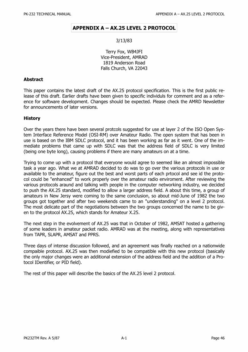
PK-232 TECHNICAL MANUAL APPENDIX A – AX.25 LEVEL 2 PROTOCOL
PK232TM Rev. A 5/87 A-1 Page 46
APPENDIX A – AX.25 LEVEL 2 PROTOCOL
3/13/83
Terry Fox, WB4JFIVice-President, AMRAD1819 Anderson Road
Falls Church, VA 22043
Abstract
This paper contains the latest draft of the AX.25 protocol specification. This is the first public re-lease of this draft. Earlier drafts have been given to specific individuls for comment and as a refer-ence for software development. Changes should be expected. Please check the AMRD Newsletterfor announcements of later versions.
History
Over the years there have been several protcols suggested for use at layer 2 of the ISO Open Sys-tem Interface Reference Model (OSI-RM) over Amateur Radio. The open system that has been inuse is based on the IBM SDLC protocol, and it has been working as far as it went. One of the im-mediate problems that came up with SDLC was that the address field of SDLC is very limited(being one byte long), causing problems if there are many amateurs on at a time.
Trying to come up with a protocol that everyone would agree to seemed like an almost impossibletask a year ago. What we at AMRAD decided to do was to go over the various protocols in use oravailable to the amateur, figure out the best and worst parts of each prtocol and see id the proto-col could be "enhanced" to work properly over the amateur radio enviroment. After reviewing thevarious protocols araund and talking with people in the computer networking industry, we decidedto push the AX.25 standard, modified to allow a larger address field. A about this time, a group ofamateurs in New Jersy were coming to the same conclusion, so about mid-June of 1982 the twogroups got together and after two weekends came to an "understanding" on a level 2 protocol.The most delicate part of the negotiations between the two groups concerned the name to be giv-en to the protocol AX.25, which stands for Amateur X.25.
The next step in the evolvement of AX.25 was that in October of 1982, AMSAT hosted a gatheringof some leaders in amateur packet radio. AMRAD was at the meeting, along with representativesfrom TAPR, SLAPR, AMSAT and PPRS.
Three days of intense discussion followed, and an agreement was finally reached on a nationwidecompaible protocol. AX.25 was then modiefied to be compatible with this new protocol (basicallythe only major changes were an additional extension of the address field and the addition of a Pro-tocol IDentifier, or PID field).
The rest of this paper will describe the basics of the AX.25 level 2 protocol.

PK-232 TECHNICAL MANUAL APPENDIX A – AX.25 LEVEL 2 PROTOCOL
PK232TM Rev. A 5/87 A-2 Page 47
AX.25 Layer 2 Protocol Specification
A.1 Scope and Field of Operation
In order to provide a mechanism for the reliable transport of data between two signaling termi-nals, it is necessary to define a protocol that can accept and deliver data over a variety of types ofcommunications links. The AX.25 Link- Layer Protocol is designed to provide this service, inde-pendent of any other level that may or may not exist.
This protocol conforms to ISO Recommendations 3309, 4335 (including DAD 1&2) and 6256 high-level data link control (HDLC) and uses some terminology found in these documents. It also con-forms with ANSI X3.66, which describes ADCCP, balanced mode.
This protocol follows, in principle, the CCITT X.25 Recommendation, with the exception of an ex-tended address field and the addition of the Unnumbered Information (UI) frame. It also followsthe principles of CCITT Recommendation Q.921 (LAPD) in the use of multiple links, distinguishedby the address field, on a single shared channel.
As defined, this protocol will work equally well in either half- or full-duplex Amateur Radio environ-ments. This protocol has been designed to work equally well for direct connections between twoindividual amateur packet-radio stations or an individual station and a multiport controller.
This protocol allows for the establishment of more than one link-layer connection per device, if thedevice is so capable. This protocol does not prohibit self-connections. A self-connection is consid-ered to be when a device establishes a link to itself using its own address for both the source anddestination of the frame.
Most link-layer protocols assume that one primary (or master) device (generally called a DCE, ordata circuit- terminating equipment) is connected to one or more secondary (or slave) device(s)(usually called a DTE, or data terminating equipment). This type of unbalanced operation is notpractical in a shared-RF Amateur Radio environment. Instead, AX.25 assumes that both ends ofthe link are of the same class, thereby eliminating the two different classes of devices. The termDXE is used in this protocol specification to describe the balanced type of device found in amateurpacket radio.
A.2 Frame Structure
Link layer packet radio transmissions are sent in small blocks of data, called frames. Each frame ismade up of several smaller groups, called fields. Fig.1 shows the three basic types of frames. Notethat the first bit to be transmitted is on the left side.
Fig. 1A – U and S frame construction
First Bit Sent
Flag Address Control FCS Flag
01111110 112/560 Bits 8 Bits 16 Bits 01111110
Fig. 1B – Information frame construction
First Bit Sent
Flag Address Control PID Info. FCS Flag
01111110 112/560 Bits 8 Bits 8 Bits N*8 Bits 16 Bits 01111110
Each field is made up of an integral number of octets (or bytes), and serves a specific function asoutlined below.

PK-232 TECHNICAL MANUAL APPENDIX A – AX.25 LEVEL 2 PROTOCOL
PK232TM Rev. A 5/87 A-3 Page 48
A.2.1 Flag Field
The flag field is one octet long. Since the flag is used to delimit frames, it occurs at both the begin-ning and end of each frame. Two frames may share one flag, which would denote the end of thefirst frame, and the start of the next frame. A flag consists of a zero followed by six ones followedby another zero, or 01111110 (7E hex). As a result of bit stuffing (see A.2.6, below), this sequenceis not allowed to occur anywhere else inside a complete frame.
A.2.2 Address Field
The address field is used to identify both the source of the frame and its destination. In addition,the address field contains the command/response information and facilities for level 2 repeater op-eration. The encoding of the address field is described in A.2.13.
A.2.3 Control Field
The control field is used to identify the type of frame being passed and control several attributesof the level 2 connection. It is one octet in length, and its encoding is discussed in A.3.2.1, below.
A.2.4 PID Field
The Protocol Identifier (PID) field shall appear in information frames (I and UI) only. It identifieswhat kind of layer 3 protocol, if any, is in use.
The PID itself is not included as part of the octet count of the information field. The encoding ofthe PID is as follows:
HEXM LS SB B
Translation
0x01 00000001 ISO 8208/CCITT X.25 PLP
0x06 00000110 Compressed TCP/IP packet. Van Jacobson (RFC 1144)
0x07 00000111 Uncompressed TCP/IP packet. Van Jacobson (RFC 1144)
0x08 00001000 Segmentation fragment
** yy01yyyy AX.25 layer 3 implemented.
** yy10yyyy AX.25 layer 3 implemented.
0xC3 11000011 TEXNET datagram protocol
0xC4 11000100 Link Quality Protocol
0xCA 11001010 Appletalk
0xCB 11001011 Appletalk ARP
0xCC 11001100 ARPA Internet Protocol
0xCD 11001101 ARPA Address resolution
0xCE 11001110 FlexNet
0xCF 11001111 NET/ROM
0xF0 11110000 No layer 3 protocol implemented.
0xFF 11111111 Escape character. Next octet contains more Level 3 protocol information.
Where:A y indicates all combinations used.

PK-232 TECHNICAL MANUAL APPENDIX A – AX.25 LEVEL 2 PROTOCOL
PK232TM Rev. A 5/87 A-4 Page 49
Note:All forms of yy11yyyy and yy00yyyy other than those listed above are reserved at this time
for future level 3 protocols. The assignment of these formats is up to amateur agreement. It isrecommended that the creators of level 3 protocols contact the ARRL Ad Hoc Committee on DigitalCommunications for suggested encodings.
A.2.5 Information Field
The information field is used to convey user data from one end of the link to the other. I fields areallowed in only three types of frames: the I frame, the UI frame, and the FRMR frame. The I fieldcan be up to 256 octets long, and shall contain an integral number of octets. These constraints ap-ply prior to the insertion of zero bits as specified in A.2.6, below. Any information in the I fieldshall be passed along the link transparently, except for the zero-bit insertion (see A.2.6) necessaryto prevent flags from accidentally appearing in the I field.
A.2.6 Bit Stuffing
In order to assure that the flag bit sequence mentioned above doesn't appear accidentally any-where else in a frame, the sending station shall monitor the bit sequence for a group of five ormore contiguous one bits. Any time five contiguous one bits are sent the sending station shall in-sert a zero bit after the fifth one bit. During frame reception, any time five contiguous one bits arereceived, a zero bit immediately following five one bits shall be discarded.
A.2.7 Frame-Check Sequence
The frame-check sequence (FCS) is a sixteen-bit number calculated by both the sender and re-ceiver of a frame. It is used to insure that the frame was not corrupted by the medium used to getthe frame from the sender to the receiver. It shall be calculated in accordance with ISO 3309(HDLC) Recommendations.
A.2.8 Order of Bit Transmission
With the exception of the FCS field, all fields of an AX.25 frame shall be sent with each octet'sleast-significant bit first. The FCS shall be sent most-significant bit first.
A.2.9 Invalid FramesAny frame consisting of less than 136 bits (including the opening and closing flags), not boundedby opening and closing flags, or not octet aligned (an integral number of octets), shall be consid-ered an invalid frame by the link layer. See also A.4.4.4, below.
A.2.10 Frame Abort
If a frame must be prematurely aborted, at least fifteen contiguous ones shall be sent with no bitstuffing added.
A.2.11 Interframe Time Fill
Whenever it is necessary for a DXE to keep its transmitter on while not actually sending frames,the time between frames should be filled with contiguous flags.
A.2.12 Link Channel States
Not applicable.

PK-232 TECHNICAL MANUAL APPENDIX A – AX.25 LEVEL 2 PROTOCOL
PK232TM Rev. A 5/87 A-5 Page 50
A.2.13 Address-Field Encoding
The address field of all frames shall be encoded with both the destination and source amateur callsigns for the frame. Except for the Secondary Station Identifier (SSID), the address field should bemade up of upper-case alpha and numeric ASCII characters only. If level 2 amateur "repeaters"are to be used, their call signs shall also be in the address field.
The HDLC address field is extended beyond one octet by assigning the least-significant bit of eachoctet to be an "extension bit". The extension bit of each octet is set to zero, to indicate the nextoctet contains more address information, or one, to indicate this is the last octet of the HDLC ad-dress field. To make room for this extension bit, the amateur Radio call sign information is shiftedone bit left.
A.2.13.1 Nonrepeater Address-Field Encoding
If level 2 repeaters are not being used, the address field is encoded as shown in Fig. 2. The desti-nation address is the call sign and SSID of the amateur radio station to which the frame is ad-dressed, while the source address contains the amateur call sign and SSID of the station that sentthe frame. These call signs are the call signs of the two ends of a level 2 AX.25 link only.
Fig. 2 – Nonrepeater Address-Field Encoding
First Octet Sent
Address Field of Frame
Destination Address Source Address
A1 A2 A3 A4 A5 A6 A7 A8 A9 A10 A11 A12 A13 A14
A1 through A14 are the fourteen octets that make up the two address subfields of the addressfield. The destination subaddress is seven octets long (A1 thru A7), and is sent first. This addresssequence provides the receivers of frames time to check the destination address subfield to see ifthe frame is addressed to them while the rest of the frame is being received. The source addresssubfield is then sent in octets A8 through A14. Both of these subfields are encoded in the samemanner, except that the last octet of the address field has the HDLC address extension bit set.
There is an octet at the end of each address subfield that contains the Secondary Station Identifier(SSID). The SSID subfield allows an Amateur Radio operator to have more than one packet-radiostation operating under the same call sign. This is useful when an amateur wants to put up a re-peater in addition to a regular station, for example. The C bits (see A.4.1.2, below) and H bit (seeA.2.13.2, below) are also contained in this octet, along with two bits which are reserved for futureuse.
Fig. 3A shows a typical AX.25 frame in the nonrepeater mode of operation.

PK-232 TECHNICAL MANUAL APPENDIX A – AX.25 LEVEL 2 PROTOCOL
PK232TM Rev. A 5/87 A-6 Page 51
Fig. 3A – Nonrepeater AX.25 frame
Octet ASCII Bin. Data Hex Data
Flag 01111110 7E
A1 K 10010110 96
A2 8 01110000 70
A3 M 10011010 9A
A4 M 10011010 9A
A5 O 10011110 9E
A6 space 01000000 40
A7 SSID 11100000 E0
A8 W 10101110 AE
A9 B 10000100 84
A10 4 01100100 68
A11 J 10010100 94
A12 F 10001100 8C
A13 I 10010010 92
A14 SSID 01100001 61
Control I 00111110 3E
PID none 11110000 F0
FCS part 1 xxxxxxxx HH
FCS part 2 xxxxxxxx HH
Flag 01111110 7E
Bit position 76543210
The frame shown is an I frame, not going through a level 2 repeater, from WB4JFI (SSID=0) toK8MMO (SSID=0), with no level 3 protocol. The P/F bit is set; the receive sequence number (N(R))is 1; the send sequence number (N(S)) is 7.
A.2.13.1.1 Destination Subfield Encoding
Fig. 3 shows how an amateur call sign is placed in the destination address subfield, occupying oc-tets A1 thru A7.
Fig. 3 – Destination Field Encoding
Octet ASCII Bin. Data Hex Data
A1 W 10101110 AE
A2 B 10000100 84
A3 4 01101000 68
A4 J 10010100 94
A5 F 10001100 8C
A6 I 10010010 92
A7 SSID CRRSSID0Bit Position 76543210
Where:1. The top octet (A1) is the first octet sent, with bit 0 of each octet being the first bit sent, and
bit 7 being the last bit sent.2. The first (low-order or bit 0) bit of each octet is the HDLC address extension bit, which is set to
zero on all but the last octet in the address field, where it is set to one.3. The bits marked "r" are reserved bits. They may be used in an agreed-upon manner in individ-
ual networks. When not implemented, they should be set to one.

PK-232 TECHNICAL MANUAL APPENDIX A – AX.25 LEVEL 2 PROTOCOL
PK232TM Rev. A 5/87 A-7 Page 52
4. The bit marked "C" is used as the command/response bit of an AX.25 frame, as outlined inA.4.1.2 below.
5. The characters of the call sign should be standard seven-bit ASCII (upper case only) placed inthe leftmost seven bits of the octet to make room for the address extension bit. If the call signcontains fewer than six characters, it should be padded with ASCII spaces between the last callsign character and the SSID octet.
6. The 0000 SSID is reserved for the first personal AX.25 station. This establishes one standardSSID for "normal" stations to use for the first station.
A.2.13.2 Level 2 Repeater-Address Encoding
If a frame is to go through level 2 amateur packet repeater(s), there is an additional address sub-field appended to the end of the address field. This additional subfield contains the call sign(s) ofthe repeater(s) to be used. This allows more than one repeater to share the same RF channel. Ifthis subfield exists, the last octet of the source subfield has its address extension bit set to zero,indicating that more address-field data follows. The repeater-address subfield is encoded in thesame manner as the destination and source address subfields, except for the most-significant bitin the last octet, called the "H" bit. The H bit is used to indicate whether a frame has been re-peated or not.
In order to provide some method of indicating when a frame has been repeated, the H bit is set tozero on frames going to a repeater. The repeater will set the H bit to one when the frame is re-transmitted. Stations should monitor the H bit, and discard any frames going to the repeater (up-link frames), while operating through a repeater. Fig. 4 shows how the repeater- address subfieldis encoded. Fig. 4A is an example of a complete frame after being repeated.
Fig. 4 – Repeater-address encoding
Octet ASCII Bin. Data Hex Data
A15 W 10101110 AE
A16 B 10000100 84
A17 4 01101000 68
A18 J 10010100 94
A19 F 10001100 8C
A20 I 10010010 92
A21 SSID HRRSSID1Bit Order --> 76543210
Where:1. The top octet is the first octet sent, with bit 0 being sent first and bit 7 sent last of each octet.2. As with the source and destination address subfields discussed above, bit 0 of each octet is the
HDLC address extension bit, which is set to zero on all but the last address octet, where it isset to one.
3. The "R" bits are reserved in the same manner as in the source and destination subfields.4. The "H" bit is the has-been-repeated bit. It is set to zero whenever a frame has not been re-
peated, and set to one by the repeater when the frame has been repeated.

PK-232 TECHNICAL MANUAL APPENDIX A – AX.25 LEVEL 2 PROTOCOL
PK232TM Rev. A 5/87 A-8 Page 53
Fig. 4A – AX.25 frame in repeater mode
Octet ASCII Bin. Data Hex Data
Flag 01111110 7E
A1 K 10010110 96
A2 8 01110000 70
A3 M 10011010 9A
A4 M 10011010 9A
A5 O 10011110 9E
A6 space 01000000 40
A7 SSID 11100000 E0
A8 W 10101110 AE
A9 B 10000100 84
A10 4 01100100 68
A11 J 10010100 94
A12 F 10001100 8C
A13 I 10010010 92
A14 SSID 01100000 60
A15 W 10101110 AE
A16 B 10000100 84
A17 4 01101000 68
A18 J 10010100 94
A19 F 10001100 8C
A20 I 10010010 92
A21 SSID 11100011 E3
Control I 00111110 3E
PID none 11110000 F0
FCS part 1 xxxxxxxx HH
FCS part 2 xxxxxxxx HH
Flag 01111110 7E
Bit position 76543210
The above frame is the same as Fig. 3A, except for the addition of a repeater-address subfield(WB4JFI, SSID=1). The H bit is set, indicating this is from the output of the repeater.
A.2.13.3 Multiple Repeater Operation
The link-layer AX.25 protocol allows operation through more than one repeater, creating a primi-tive frame routing mechanism. Up to eight repeaters may be used by extending the repeater-ad-dress subfield. When there is more than one repeater address, the repeater address immediatelyfollowing the source address subfield will be considered the address of the first repeater of a multi-ple-repeater chain. As a frame progresses through a chain of repeaters, each successive repeaterwill set the H bit (has-been-repeated bit) in its SSID octet, indicating that the frame has been suc-cessfully repeated through it. No other changes to the frame are made (except for the necessaryrecalculation of the FCS). The destination station can determine the route the frame took to eachit by examining the address field.
The number of repeater addresses is variable. All but the last repeater address will have the ad-dress extension bits of all octets set to zero, as will all but the last octet (SSID octet) of the last re-peater address. The last octet of the last repeater address will have the address extension bit setto one, indicating the end of the address field.

PK-232 TECHNICAL MANUAL APPENDIX A – AX.25 LEVEL 2 PROTOCOL
PK232TM Rev. A 5/87 A-9 Page 54
It should be noted that various timers (see A.4.7, below) may have to be adjusted to accommo-date the additional delays encountered when a frame must pass through a multiple-repeaterchain, and the return acknowledgement must travel through the same path before reaching thesource device.
It is anticipated that multiple-repeater operation is a temporary method of interconnecting stationsover large distances until such time that a layer 3 protocol is in use. Once this layer 3 protocol be-comes operational, repeater chaining should be phased out.
A.3 Elements of Procedure
A.3.1
The elements of procedure are defined in terms of actions that occur on receipt of frames.
A.3.2 Control-Field Formats and State Variables
A.3.2.1 Control-Field Formats
The control field is responsible for identifying the type of frame being sent, and is also used toconvey commands and responses from one end of the link to the other in order to maintain properlink control.
The control fields used in AX.25 use the CCITT X.25 control fields for balanced operation (LAPB),with an additional control field taken from ADCCP to allow connectionless and round- table opera-tion.
There are three general types of AX.25 frames. They are the Information frame (I frame), theSupervisory frame (S frame), and the Unnumbered frame (U frame). Fig. 5 shows the basic formatof the control field associated with these types of frames.
Fig. 5 – Control-field formats
Control-FieldType
Control-Field Bits
7 6 5 4 3 2 1 0
I Frame N(R) P N(S) 0
S Frame N(R) P/F S S 0 1
U Frame M M M P/F M M 1 1
Where:1. Bit 0 is the first bit sent and bit 7 is the last bit sent of the control field.2. N(S) is the send sequence number (bit 1 is the LSB).3. N(R) is the receive sequence number (bit 5 is the LSB).4. The "S" bits are the supervisory function bits, and their encoding is discussed in A.3.4.2.5. The "M" bits are the unnumbered frame modifier bits and their encoding is discussed in
A.3.4.3.6. The P/F bit is the Poll/Final bit. Its function is described in A.3.3. The distinction between com-
mand and response, and therefore the distinction between P bit and F bit, is made by address-ing rules discussed in A.4.1.2.

PK-232 TECHNICAL MANUAL APPENDIX A – AX.25 LEVEL 2 PROTOCOL
PK232TM Rev. A 5/87 A-10 Page 55
A.3.2.1.1 Information-Transfer Format
All I frames have bit 0 of the control field set to zero. N(S) is the sender's send sequence number(the send sequence number of this frame). N(R) is the sender's receive sequence number (the se-quence number of the next expected received frame). These numbers are described in A.3.2.4. Inaddition, the P/F bit is to be used as described in A.4.2.
A.3.2.1.2 Supervisory Format
Supervisory frames are denoted by having bit 0 of the control field set to one, and bit 1 of the con-trol field set to zero. S frames provide supervisory link control such as acknowledging or request-ing retransmission of I frames, and link- level window control. Since S frames do not have an infor-mation field, the sender's send variable and the receiver's receive variable are not incremented forS frames. In addition, the P/F bit is used as described in A.4.2.
A.3.2.1.3 Unnumbered Format
Unnumbered frames are distinguished by having both bits 0 and 1 of the control field set to one. Uframes are responsible for maintaining additional control over the link beyond what is accom-plished with S frames. They are also responsible for establishing and terminating link connections.U frames also allow for the transmission and reception of information outside of the normal flowcontrol. Some U frames may contain information and PID fields. The P/F bit is used as described inA.4.2.
A.3.2.2 Control-Field Parameters
A.3.2.3 Sequence Numbers
Every AX.25 I frame shall be assigned, modulo 8, a sequential number from 0 to 7. This will allowup to seven outstanding I frames per level 2 connection at a time.
A.3.2.4 Frame Variables and Sequence Numbers
A.3.2.4.1 Send State Variable V(S)
The send state variable is a variable that is internal to the DXE and is never sent. It contains thenext sequential number to be assigned to the next transmitted I frame. This variable is updatedupon the transmission of each I frame.
A.3.2.4.2 Send Sequence Number N(S)
The send sequence number is found in the control field of all I frames. It contains the sequencenumber of the I frame being sent. Just prior to the transmission of the I frame, N(S) is updated toequal the send state variable.
A.3.2.4.3 Receive State Variable V(R)
The receive state variable is a variable that is internal to the DXE. It contains the sequence num-ber of the next expected received I frame. This variable is updated upon the reception of an error-free I frame whose send sequence number equals the present received state variable value.
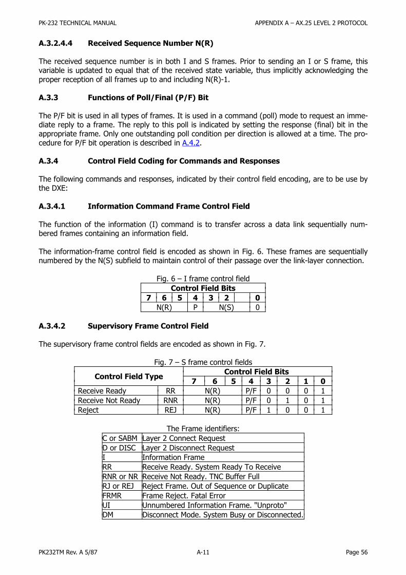
PK-232 TECHNICAL MANUAL APPENDIX A – AX.25 LEVEL 2 PROTOCOL
PK232TM Rev. A 5/87 A-11 Page 56
A.3.2.4.4 Received Sequence Number N(R)
The received sequence number is in both I and S frames. Prior to sending an I or S frame, thisvariable is updated to equal that of the received state variable, thus implicitly acknowledging theproper reception of all frames up to and including N(R)-1.
A.3.3 Functions of Poll/Final (P/F) Bit
The P/F bit is used in all types of frames. It is used in a command (poll) mode to request an imme-diate reply to a frame. The reply to this poll is indicated by setting the response (final) bit in theappropriate frame. Only one outstanding poll condition per direction is allowed at a time. The pro-cedure for P/F bit operation is described in A.4.2.
A.3.4 Control Field Coding for Commands and Responses
The following commands and responses, indicated by their control field encoding, are to be use bythe DXE:
A.3.4.1 Information Command Frame Control Field
The function of the information (I) command is to transfer across a data link sequentially num-bered frames containing an information field.
The information-frame control field is encoded as shown in Fig. 6. These frames are sequentiallynumbered by the N(S) subfield to maintain control of their passage over the link-layer connection.
Fig. 6 – I frame control field
Control Field Bits
7 6 5 4 3 2 0
N(R) P N(S) 0
A.3.4.2 Supervisory Frame Control Field
The supervisory frame control fields are encoded as shown in Fig. 7.
Fig. 7 – S frame control fields
Control Field TypeControl Field Bits
7 6 5 4 3 2 1 0
Receive Ready RR N(R) P/F 0 0 0 1
Receive Not Ready RNR N(R) P/F 0 1 0 1
Reject REJ N(R) P/F 1 0 0 1
The Frame identifiers:
C or SABM Layer 2 Connect Request
D or DISC Layer 2 Disconnect Request
I Information Frame
RR Receive Ready. System Ready To Receive
RNR or NR Receive Not Ready. TNC Buffer Full
RJ or REJ Reject Frame. Out of Sequence or Duplicate
FRMR Frame Reject. Fatal Error
UI Unnumbered Information Frame. "Unproto"
DM Disconnect Mode. System Busy or Disconnected.

PK-232 TECHNICAL MANUAL APPENDIX A – AX.25 LEVEL 2 PROTOCOL
PK232TM Rev. A 5/87 A-12 Page 57
A.3.4.2.1 Receive Ready (RR) Command and Response
Receive Ready is used to do the following:
1. to indicate that the sender of the RR is now able to receive more I frames.2. to acknowledge properly received I frames up to, and including N(R)-1, and3. to clear a previously set busy condition created by an RNR command having been sent.
The status of the DXE at the other end of the link can be requested by sending a RR commandframe with the P-bit set to one.
A.3.4.2.2 Receive Not Ready (RNR) Command and Response
Receive Not Ready is used to indicate to the sender of I frames that the receiving DXE is tempora-rily busy and cannot accept any more I frames. Frames up to N(R)-1 are acknowledged. Any Iframes numbered N(R) and higher that might have been caught between states and not acknowl-edged when the RNR command was sent are not acknowledged.
The RNR condition can be cleared by the sending of a UA, RR, REJ, or SABM frame.
The status of the DXE at the other end of the link can be requested by sending a RNR commandframe with the P bit set to one.
A.3.4.2.3 Reject (REJ) Command and Response
The reject frame is used to request retransmission of I frames starting with N(R). Any frames thatwere sent with a sequence number of N(R)-1 or less are acknowledged. Additional I frames maybe appended to the retransmission of the N(R) frame if there are any.
Only one reject frame condition is allowed in each direction at a time. The reject condition iscleared by the proper reception of I frames up to the I frame that caused the reject condition tobe initiated.
The status of the DXE at the other end of the link can be requested by sending a REJ commandframe with the P bit set to one.
A.3.4.3 Unnumbered Frame Control Fields
Unnumbered frame control fields are either commands or responses. Fig. 8 shows the layout of Uframes implemented within this protocol.
Fig. 8 – U frame control fields
Control Field TypeControl Field Bits
7 6 5 4 3 2 1 0
Set Asynchronous Balanced Mode SABM Res 0 0 1 P 1 1 1 1
Disconnect DISC Cm 0 1 0 P 0 0 1 1
Disconnected Mode DM Res 0 0 0 F 1 1 1 1
Unnumbered Acknowledge UA Res 0 1 1 F 0 0 1 1
Frame Reject FRMR Res 1 0 0 F 0 1 1 1
Unnumbered Information UI Either 0 0 0 P/F 0 0 1 1

PK-232 TECHNICAL MANUAL APPENDIX A – AX.25 LEVEL 2 PROTOCOL
PK232TM Rev. A 5/87 A-13 Page 58
A.3.4.3.1 Set Asynchronous Balanced Mode (SABM) Command
The SABM command is used to place 2 DXEs in the asynchronous balanced mode. This is a bal-anced mode of operation known as LAPB where both devices are treated as equals.
Information fields are not allowed in SABM commands. Any outstanding I frames left when theSABM command is issued will remain unacknowledged.
The DXE confirms reception and acceptance of a SABM command by sending a UA response frameat the earliest opportunity. If the DXE is not capable of accepting a SABM command, it should re-spond with a DM frame if possible.
A.3.4.3.2 Disconnect (DISC) Command
The DISC command is used to terminate a link session between two stations. No information fieldis permitted in a DISC command frame.
Prior to acting on the DISC frame, the receiving DXE confirms acceptance of the DISC by issuing aUA response frame at its earliest opportunity. The DXE sending the DISC enters the disconnectedstate when it receives the UA response.
Any unacknowledged I frames left when this command is acted upon will remain unacknowledged.
A.3.4.3.3 Frame Reject (FRMR) Response
A.3.4.3.3.1
The FRMR response frame is sent to report that the receiver of a frame cannot successfully proc-ess that frame and that the error condition is not correctable by sending the offending frameagain. Typically this condition will appear when a frame without an FCS error has been receivedwith one of the following conditions:
1. The reception of an invalid or not implemented command or response frame.2. The reception of an I frame whose information field exceeds the agreed-upon length. (See
A.4.7.3, below.)3. The reception of an improper N(R). This usually happens when the N(R) frame has already
been sent and acknowledged, or when N(R) is out of sequence with what was expected.4. The reception of a frame with an information field where one is not allowed, or the reception
of a U or S frame whose length is incorrect. Bits W and Y described in A.3.4.3.3.2 should bothbe set to one to indicate this condition.
5. The reception of a supervisory frame with the F bit set to one, except during a timer recoverycondition (see A.4.4.9), or except as a reply to a command frame sent with the P bit set toone. Bit W (described in A.3.4.3.3.2) should be set to one.
6. The reception of an unexpected UA or DM response frame. Bit W should be set to one.7. The reception of a frame with an invalid N(S). Bit W should be set to one.
An invalid N(R) is defined as one which points to an I frame that previously has been transmittedand acknowledged, or an I frame which has not been transmitted and is not the next sequential Iframe pending transmission.
An invalid N(S) is defined as an N(S) that is equal to the last transmitted N(R)+k and is equal tothe received state variable V(R), where k is the maximum number of outstanding informationframes as defined in A.4.7.4 below.
PK-232 TECHNICAL MANUAL APPENDIX A – AX.25 LEVEL 2 PROTOCOL
PK232TM Rev. A 5/87 A-14 Page 59
An invalid or not implemented command or response is defined as a frame with a control field thatis unknown to the receiver of this frame.
A.3.4.3.3.2
When a FRMR frame is sent, an information field is added to the frame that contains additional in-formation indicating where the problem occurred. This information field is three octets long and isshown in Fig. 9.
Fig. 9 – FRMR frame information field
Information Field Bits
23 22 21 20 19 18 17 16 15 14 13 12 11 10 9 8 7 6 5 4 3 2 1 0
0 0 0 0 Z Y X W V(R)CR
V(S) 0Rejected Frame
Control Field
Where:1. The rejected frame control field carries the control field of the frame that caused the reject
condition. It is in bits 0-7 of the information field.2. V(S) is the current send state variable of the device reporting the rejection (bit 9 is the low
bit).3. The CR bit is set to zero to indicate the rejected frame was a command, or one if it was a re-
sponse.4. V(R) is the current receive state variable of the device reporting rejection (bit 13 is the low
bit).5. If W is set to 1, the control field received was invalid or not implemented.6. If X is set to 1, the frame that caused the reject condition was considered invalid because it
was a U or S frame that had an information field that is not allowed. Bit W must be set to 1 inaddition to the X bit.
7. If Y is set to 1, the control field received and returned in bits exceeded the maximum allowedunder this recommendation in A.4.7.3, below.
8. If A is set to 1, the control field received and returned in bits 1 to 8 contained an invalid N(R).9. Bits 8, and 20 to 23 are set to 0.
A.3.4.3.4 Unnumbered Acknowledge (UA) Response
The UA response frame is sent to acknowledge the reception and acceptance of a SABM or DISCcommand frame. A received command is not actually processed until the UA response frame issent. Information fields are not permitted in a UA frame.
A.3.4.3.5 Disconnected Mode (DM) Response
The disconnected mode response is sent whenever a DXE receives a frame other than a SABM orUI frame while in a disconnected mode. It is also sent to request a set mode command, or to indi-cate it cannot accept a connection at the moment. The DM response does not have an informationfield.
Whenever a SABM frame is a received, and it is determined that a connection is not possible, a DMframe shall be sent. This will indicate that the called station cannot accept a connection at thattime.
While a DXE is in the disconnected mode, it will respond to any command other than a SABM or UIframe with a DM response with the P/F bit set to 1.
PK-232 TECHNICAL MANUAL APPENDIX A – AX.25 LEVEL 2 PROTOCOL
PK232TM Rev. A 5/87 A-15 Page 60
A.3.4.3.6 Unnumbered Information (UI) Frame
The Unnumbered Information frame contains PID and information fields and is used to pass infor-mation along the link outside the normal information controls. This allows information fields to goback and forth on the link bypassing flow control. Since these frames are not acknowledgeable, ifone gets obliterated, there is no way to recover it. A received UI frame with the P bit set shallcause a response to be transmitted. This response shall be a DM frame when in the disconnectedstate or a RR (or RNR, if appropriate) frame in the information transfer state.
A.3.5 Link Error Reporting and Recovery
There are several link-layer errors that are recoverable without terminating the connection. Theseerror situations may occur as a result of malfunctions within the DXE, or if transmission errors oc-cur.
A.3.5.1 DXE Busy Condition
When a DXE becomes temporarily unable to receive I frames, such as when receive buffers arefull, it will send a Receive Not Ready (RNR) frame. This informs the other DXE that this DXE can-not handle any more I frames at the moment. This condition is usually cleared by the sending of aUA, RR, REJ, or SABM command frame.
A.3.5.2 Send Sequence Number Error
If the send sequence number, N(S), of an otherwise error- free received frame does not match thereceive state variable, V(R), a send sequence error has occurred, and the information field will bediscarded. The receiver will not acknowledge this frame, or any other I frames, until N(S) matchesV(R).
The control field of the erroneous I frame(s) will be accepted so that link supervisory functionssuch as checking the P/F bit can still be performed. Because of this updating, the retransmitted Iframe may have an updated P bit and N(R).
A.3.5.3 Reject (REJ) Recovery
REJ is used to request a retransmission of I frames following the detection of a N(S) sequence er-ror. Only one outstanding "sent REJ" condition is allowed at a time. This condition is cleared whenthe requested I frame has been received.
A DXE receiving the REJ command will clear the condition by resending all outstanding I frames(up to the window size), starting with the one indicated in N(R) of the REJ frame.
A.3.5.4 Time-out Error Recovery
A.3.5.4.1 T1 Timer Recovery
If a DXE, due to a transmission error, does not receive (or receives and discards) a single I frameor the last I frame in a sequence of I frames, it will not detect a send-sequence- number error,and therefore will not transmit a REJ. The DXE which transmitted the unacknowledged I frame(s)shall, following the completion of time-out period T1, take appropriate recovery action to deter-mine when I frame retransmission should begin as described in A.4.4.9, below. This condition iscleared by the reception of an acknowledgement for the sent frame(s), or by the link being reset.See A.4.6.

PK-232 TECHNICAL MANUAL APPENDIX A – AX.25 LEVEL 2 PROTOCOL
PK232TM Rev. A 5/87 A-16 Page 61
A.3.5.4.2 Timer T3 Recovery
Timer T3 is used to assure the link is still functional during periods of low information transfer.Whenever T1 is not running (no outstanding I frames), T3 is used to periodically poll the otherDXE of a link. When T3 times out, a RR or RNR frame is transmitted as a command and with the Pbit set. The waiting acknowledgement procedure (A.4.4.9, below) is then executed.
A.3.5.5 Invalid Frame or FCS Error
If an invalid frame is received, or a frame is received with an FCS error, that frame will be dis-carded with no action taken.
A.3.5.6 Frame Rejection Condition
A frame rejection condition occurs when an otherwise error-free frame has been received with oneof the conditions listed in A.3.4.3.3 above.
Once a rejection error occurs, no more I frames are accepted (except for the examination of theP/F bit) until the error is resolved. The error condition is reported to the other DXE by sending aFRMR response frame. See A.4.5.
A.4 Description of AX.25 Procedures
The following describes the procedures used to setup, use, and disconnect a balanced link be-tween two DXE stations.
A.4.1 Address Field Operation
A.4.1.1 Address Information
All transmitted frames shall have address fields conforming to A.2.13, above. All frames shall haveboth the destination device and the source device addresses in the address field, with the destina-tion address coming first. This allows many links to share the same RF channel. The destinationaddress is always the address of the station(s) to receive the frame, while the source address con-tains the address of the device that sent the frame.
The destination address can be a group name or club call sign if the point-to-multipoint operationis allowed. Operation with destination addresses other than actual amateur call signs is a subjectfor further study.
A.4.1.2 Command/Response Procedure
AX.25 Version 2.0 has implemented the command/response information in the address field. In or-der to maintain compatibility with previous versions of AX.25, the command/response informationis conveyed using two bits.
An upward-compatible AX.25 DXE can determine whether it is communicating with a DXE using anolder version of this protocol by testing the command/response bit information located in bit 7 ofthe SSID octets of both the destination and source address subfields. If both C bits are set to zero,the device is using the older protocol. The newer version of the protocol always has one of thesetwo bits set to one and the other set to zero, depending on whether the frame is a command or aresponse.

PK-232 TECHNICAL MANUAL APPENDIX A – AX.25 LEVEL 2 PROTOCOL
PK232TM Rev. A 5/87 A-17 Page 62
The command/response information is encoded into the address field as shown in Fig. 10.
Fig. 10 – Command/Response encoding
Frame Type Dest. SSID C-Bit Source SSID C-Bit
Previous versions 0 0
Command (V.2.0) 1 0
Response (V.2.0) 0 1
Previous versions 1 1
Since all frames are considered either commands or responses, a device shall always have one ofthe bits set to one, and the other bit set to zero.
The use of the command/response information in AX.25 allows S frames to be either commands orresponses. This aids maintenance of proper control over the link during the information transferstate.
A.4.2 P/F Bit Procedures
The next response frame returned by the DXE to a SABM or DISC command with the P bit set to 1will be a UA or DM response with the F bit set to 1.
The next response frame returned to an I frame with the P bit set to 1, received during the infor-mation transfer state, will be a RR, RNR, or REJ response with the F bit set to 1.
The next response frame returned to a supervisory command frame with the P bit set to 1, re-ceived during the information transfer state, will be a RR, RNR, or REJ response frame with the Fbit set to 1.
The next response frame returned to a S or I command frame with the P bit set to 1, received inthe disconnected state, will be a DM response frame with the F bit set to 1.
The P bit is used in conjunction with the time-out recovery condition discussed in A.3.5.4, above.When not used, the P/F bit is set to zero.
A.4.3 Procedures For Link Set-Up and Disconnection
A.4.3.1 LAPB Link Connection Establishment
When one DXE wishes to connect to another DXE, it will send a SABM command frame to that de-vice and start timer (T1). If the other DXE is there and able to connect, it will respond with a UAresponse frame, and reset both of its internal state variables (V(S) and V(R)). The reception of theUA response frame at the other end will cause the DXE requesting the connection to cancel the T1timer and set its internal state variables to 0.
If the other DXE doesn't respond before T1 times out, the device requesting the connection will re-send the SABM frame, and start T1 running again. The DXE should continue to try to establish aconnection until it has tried unsuccessfully N2 times. N2 is defined in A.4.7.2, below.
If, upon reception of a SABM command, the DXE decides that it cannot enter the indicated state, itshould send a DM frame.
When receiving a DM response, the DXE sending the SABM should cancel its T1 timer, and not en-ter the information- transfer state.

PK-232 TECHNICAL MANUAL APPENDIX A – AX.25 LEVEL 2 PROTOCOL
PK232TM Rev. A 5/87 A-18 Page 63
The DXE sending a SABM command will ignore and discard any frames except SABM, DISC, UA,and DM frames from the other DXE.
Frames other than UA and DM in response to a received SABM will be sent only after the link is setup and if no outstanding SABM exists.
A.4.3.2 Information-Transfer Phase
After establishing a link connection, the DXE will enter the information-transfer state. In this state,the DXE will accept and transmit I and S frames according to the procedure outlined in A.4.4, be-low.
When receiving a SABM command while in the information- transfer state, the DXE will follow theresetting procedure outlined in A.4.6 below.
A.4.3.3 Link Disconnection
A.4.3.3.1
While in the information-transfer state, either DXE may indicate a request to disconnect the link bytransmitting a DISC command frame and starting timer T1 (see A.4.7).
A.4.3.3.2
A DXE, upon receiving a valid DISC command, shall send a UA response frame and enter the dis-connected state. A DXE, upon receiving a UA or DM response to a sent DISC command, shall can-cel timer T1, and enter the disconnected state.
A.4.3.3.3
If a UA or DM response is not correctly received before T1 times out, the DISC frame should besent again and T1 restarted. If this happens N2 times, the DXE should enter the disconnectedstate.
A.4.3.4 Disconnected State
A.4.3.4.1A DXE in the disconnected state shall monitor received commands and react upon the reception ofa SABM as described in A.4.3.1 above and will transmit a DM frame in response to a DISC com-mand.
A.4.3.4.2
In the disconnected state, a DXE may initiate a link set-up as outlined in connection establishmentabove (A.4.3.1). It may also respond to the reception of a SABM and establish a connection, or itmay ignore the SABM and send a DM instead.
A.4.3.4.3
Any DXE receiving a command frame other than a SABM or UI frame with the P bit set to oneshould respond with a DM frame with the F bit set to one. The offending frame should be ignored.

PK-232 TECHNICAL MANUAL APPENDIX A – AX.25 LEVEL 2 PROTOCOL
PK232TM Rev. A 5/87 A-19 Page 64
A.4.3.4.4
When the DXE enters the disconnected state after an error condition or if an internal error has re-sulted in the DXE being in the disconnected state, the DXE should indicate this by sending a DMresponse rather than a DISC frame and follow the link disconnection procedure outlined inA.4.3.3.3, above. The DXE may then try to re-establish the link using the link set-up procedureoutlined in A.4.3.1, above.
A.4.3.5 Collision Recovery
A.4.3.5.1 Collisions in a Half-Duplex Environment
Collisions of frames in a half-duplex environment are taken care of by the retry nature of the T1timer and retransmission count variable. No other special action needs to be taken.
A.4.3.5.2 Collisions of Unnumbered Commands
If sent and received SABM or DISC command frames are the same, both DXEs should send a UAresponse at the earliest opportunity, and both devices should enter the indicated state.
If sent and received SABM or DISC commands are different, both DXEs should enter the discon-nected state and transmit a DM frame at the earliest opportunity.
A.4.3.5.3 Collision of a DM with a SABM or DISC
When an unsolicited DM response frame is sent, a collision between it and a SABM or DISC mayoccur. In order to prevent this DM from being misinterpreted, all unsolicited DM frames should betransmitted with the F bit set to zero. All SABM and DISC frames should be sent with the P bit setto one. This will prevent any confusion when a DM frame is received.
A.4.3.6 Connectionless Operation
In Amateur Radio, there is an additional type of operation that is not feasible using level 2 connec-tions. This operation is the round table, where several amateurs may be engaged in one conversa-tion. This type of operation cannot be accommodated by AX.25 link-layer connections.
The way round-table activity is implemented is technically outside the AX.25 connection, but stillusing the AX.25 frame structure.
AX.25 uses a special frame for this operation, called the Unnumbered Information (UI) frame.When this type of operation is used, the destination address should have a code word installed init to prevent the users of that particular round table from seeing all frames going through theshared RF medium. An example of this is if a group of amateurs are in a round-table discussionabout packet radio, they could put PACKET in the destination address, so they would receiveframes only from others in the same discussion. An added advantage of the use of AX.25 in thismanner is that the source of each frame is in the source address subfield, so software could bewritten to automatically display who is making what comments.
Since this mode is connectionless, there will be no requests for retransmissions of bad frames. Col-lisions will also occur, with the potential of losing the frames that collided.
A.4.4 Procedures for Information Transfer
Once a connection has been established, as outlined above, both devices are able to accept I, S,and U frames.

PK-232 TECHNICAL MANUAL APPENDIX A – AX.25 LEVEL 2 PROTOCOL
PK232TM Rev. A 5/87 A-20 Page 65
A.4.4.1 Sending I Frames
Whenever a DXE has an I frame to transmit, it will send the I frame with N(S) of the control fieldequal to its current send state variable V(S). Once the I frame is sent, the send state variable is in-cremented by one. If timer T1 is not running, it should be started. If timer T1 is running, it shouldbe restarted.
The DXE should not transmit any more I frames if its send state variable equals the last receivedN(R) from the other side of the link plus seven. If it were to send more I frames, the flow controlwindow would be exceed, and errors could result.
If a DXE is in a busy condition, it may still send I frames as long as the other device is not alsobusy.
If a DXE is in the frame-rejection mode, it will stop sending I frames.
A.4.4.2 Receiving I Frames
A.4.4.2.1
If a DXE receives a valid I frame (one with a correct FCS and whose send sequence number equalsthe receiver's receive state variable) and is not in the busy condition, it will accept the received Iframe, increment its receive state variable, and act in one of the following manners:
1. If it has an I frame to send, that I frame may be sent with the transmitted N(R) equal to its re-ceive state variable V(R) (thus acknowledging the received frame). Alternately, the device maysend a RR frame with N(R) equal to V(R), and then send the I frame.
2. If there are no outstanding I frames, the receiving device will send a RR frame with N(R) equalto V(R). The receiving DXE may wait a small period of time before sending the RR frame to besure additional I frames are not being transmitted.
A.4.4.2.2
If the DXE is in a busy condition, it may ignore any received I frames without reporting this condi-tion other than repeating the indication of the busy condition.
If a busy condition exists, the DXE receiving the busy condition indication should poll the sender ofthe busy indication periodically until the busy condition disappears.
A DXE may poll the busy DXE periodically with RR or RNR frames with the P bit set to one.
The reception of I frames that contain zero-length information fields shall be reported to the nextlevel but no information field will be transferred.
A.4.4.3 Reception of Out of Sequence Frames
When an I frame is received with a correct FCS, but its send sequence number, N(S), does notmatch the current receiver's receive state variable, the frame should be discarded. A REJ frameshall be sent with a receive sequence number equal to one higher (modulo 8) than the last cor-rectly received I frame if an uncleared N(S) sequence error condition has not been previously es-tablished. The received state variable and poll bit of the discarded frame should be checked andacted upon, if necessary, before discarding the frame.

PK-232 TECHNICAL MANUAL APPENDIX A – AX.25 LEVEL 2 PROTOCOL
PK232TM Rev. A 5/87 A-21 Page 66
A.4.4.4 Reception of Incorrect Frames
When a DXE receives a frame with an incorrect FCS, an invalid frame, or a frame with an improperaddress, that frame shall be discarded.
A.4.4.5 Receiving Acknowledgement
Whenever an I or S frame is correctly received, even in a busy condition, the N(R) of the receivedframe should be checked to see if it includes an acknowledgement of outstanding sent I frames.The T1 timer should be cancelled if the received frame actually acknowledges previously unac-knowledged frames. If the T1 timer is cancelled and there are still some frames that have beensent that are not acknowledged, T1 should be started again. If the T1 timer runs out before an ac-knowledgement is received, the device should proceed to the retransmission procedure in A.4.4.9.
A.4.4.6 Receiving Reject
Upon receiving a REJ frame, the transmitting DXE will set its send state variable to the same valueas the REJ frame's received sequence number in the control field. The DXE will then retransmitany I frame(s) outstanding at the next available opportunity conforming to the following:
1. If the DXE is not transmitting at the time, and the channel is open, the device may commenceto retransmit the I frame(s) immediately.
2. If the DXE is operating on a full-duplex channel transmitting a UI or S frame when it receives aREJ frame, it may finish sending the UI or S frame and then retransmit the I frame(s).
3. If the DXE is operating in a full-duplex channel transmitting another I frame when it receives aREJ frame, it may abort the I frame it was sending and start retransmission of the requested Iframes immediately.
4. The DXE may send just the one I frame outstanding, or it may send more than the one indi-cated if more I frames followed the first one not acknowledged, provided the total to be sentdoes not exceed the flow-control window (7 frames).
If the DXE receives a REJ frame with the poll bit set, it should respond with either a RR or RNRframe with the final bit set before retransmitting the outstanding I frame(s).
A.4.4.7 Receiving a RNR Frame
Whenever a DXE receives a RNR frame, it shall stop transmission of I frames until the busy condi-tion has been cleared. If timer T1 runs out after the RNR was received, the waiting acknowledge-ment procedure listed in A.4.4.9, below, should be performed. The poll bit may be used in con-junction with S frames to test for a change in the condition of the busied-out DXE.
A.4.4.8 Sending a Busy Indication
Whenever a DXE enters a busy condition, it will indicate this by sending a RNR response at thenext opportunity. While the DXE is in the busy condition, it may receive and process S frames, andif a received S frame has the P bit set to one, the DXE should send a RNR frame with the F bit setto one at the next possible opportunity. To clear the busy condition, the DXE should send either aRR or REJ frame with the received sequence number equal to the current receive state variable,depending on whether the last received I frame was properly received or not.

PK-232 TECHNICAL MANUAL APPENDIX A – AX.25 LEVEL 2 PROTOCOL
PK232TM Rev. A 5/87 A-22 Page 67
A.4.4.9 Waiting Acknowledgement
If timer T1 runs out waiting the acknowledgement from the other DXE for an I frame transmitted,the DXE will restart timer T1 and transmit an appropriate supervisory command frame (RR or RNR)with the P bit set. If the DXE receives correctly a supervisory response frame with the F bit set andwith an N(R) within the range from the last N(R) received to the last N(S) sent plus one, the DXEwill restart timer T1 and will set its send state variable V(S) to the received N(R). It may then re-sume with I frame transmission or retransmission, as appropriate. If, on the other hand, the DXEreceives correctly a supervisory response frame with the F bit not set, or an I frame or supervisorycommand frame, and with an N(R) within the range from the last N(R) received to the last N(S)sent plus one, the DXE will not restart timer T1, but will use the received N(R) as an indication ofacknowledgement of transmitted I frames up to and including I frame numbered N(R)-1.
If timer T1 runs out before a supervisory response frame with the F bit set is received, the DXEwill retransmit an appropriate supervisory command frame (RR or RNR) with the P bit set. After N2attempts to get a supervisory response frame with the F bit set from the other DXE, the DXE willinitiate a link resetting procedure as described in A.4.6, below.
A.4.5 Frame Rejection Conditions
A DXE shall initiate the frame-reset procedure when a frame is received with the correct FCS andaddress field during the information-transfer state with one or more of the conditions in A.3.4.3.3,above.
Under these conditions, the DXE will ask the other DXE to reset the link by transmitting a FRMR re-sponse as outlined in A.4.6.3, below.
After sending the FRMR frame, the sending DXE will enter the frame reject condition. This condi-tion is cleared when the DXE that sent the FRMR frame receives a SABM or DISC command, or aDM response frame. Any other command received while the DXE is in the frame reject state willcause another FRMR to be sent out with the same information field as originally sent.
In the frame rejection condition, additional I frames will not be transmitted, and received I framesand S frames will be discarded by the DXE.
The DXE that sent the FRMR frame shall start the T1 timer when the FRMR is sent. If no SABM orDISC frame is received before the timer runs out, the FRMR frame shall be retransmitted, and theT1 timer restarted as described in the waiting acknowledgement section (A.4.4.9) above. If theFRMR is sent N2 times without success, the link shall be reset.
A.4.6 Resetting Procedure
A.4.6.1
The resetting procedure is used to initialize both directions of data flow after a nonrecoverable er-ror has occurred. This resetting procedure is used in the information- transfer state of an AX.25link only.
A.4.6.2
A DXE shall initiate a reset procedure whenever it receives an unexpected UA response frame oran unsolicited response frame with the F bit set to one. A DXE may also initiate the reset proce-dure upon receipt of a FRMR frame. Alternatively, the DXE may respond to a FRMR by terminatingthe connection with a DISC frame.

PK-232 TECHNICAL MANUAL APPENDIX A – AX.25 LEVEL 2 PROTOCOL
PK232TM Rev. A 5/87 A-23 Page 68
A.4.6.3
A DXE shall reset the link by sending a SABM frame and starting timer T1. Upon receiving a SABMframe from the DXE previously connected to, the receiver of a SABM frame should send a UAframe back at the earliest opportunity, set its send and receive state variables, V(S) and V(R), tozero and stop T1 unless it has sent a SABM or DISC itself. If the UA is correctly received by the ini-tial DXE, it resets its send and receive state variables, V(S) and V(R), and stops timer T1. Any busycondition that previously existed will also be cleared.
If a DM response is received, the DXE will enter the disconnected state and stop timer T1. If timerT1 runs out before a UA or DM response frame is received, the SABM will be retransmitted andtimer T1 restarted. If timer T1 runs out N2 times, the DXE will enter the disconnected state, andany previously existing link conditions will be cleared.
Other commands or responses received by the DXE before completion of the reset procedure willbe discarded.
A.4.6.4
One DXE may request that the other DXE reset the link by sending a DM response frame. After theDM frame is sent, the sending DXE will then enter the disconnected state.
A.4.7 List of System Defined Parameters
A.4.7.1 Timers
To maintain the integrity of the AX.25 level 2 connection, use of these timers is recommended.
A.4.7.1.1 Acknowledgement Timer T1
The first timer, T1, is used to make sure a DXE doesn't wait forever for a response to a frame itsends. This timer cannot be expressed in absolute time, since the time required to send framesvaries greatly with the signaling rate used at level 1. T1 should take at least twice the amount oftime it would take to send maximum length frame to the other DXE, and get the proper responseframe back from the other DXE. This would allow time for the other DXE to do some processingbefore responding.
If level 2 repeaters are to be used, the value of T1 should be adjusted according to the number ofrepeaters the frame is being transferred through.
A.4.7.1.2 Response Delay Timer T2
The second timer, T2, may be implemented by the DXE to specify a maximum amount of delay tobe introduced between the time an I frame is received, and the time the resulting response frameis sent. This delay may be introduced to allow a receiving DXE to wait a short period of time to de-termine if there is more than one frame being sent to it. If more frames are received, the DXE canacknowledge them at once (up to seven), rather than acknowledge each individual frame. The useof timer T2 is not mandatory, but is recommended to improve channel efficiency. Note that, onfull-duplex channels, acknowledgements should not be delayed beyond k/2 frames to achieve max-imum throughput. The k parameter is defined in A.4.7.4, below.

PK-232 TECHNICAL MANUAL APPENDIX A – AX.25 LEVEL 2 PROTOCOL
PK232TM Rev. A 5/87 A-24 Page 69
A.4.7.1.3 Inactive Link Timer T3
The third timer, T3, is used whenever T1 isn't running to maintain link integrity. It is recom-mended that whenever there are no outstanding unacknowledged I frames or P-bit frames (duringthe information-transfer state), a RR or RNR frame with the P bit set to one be sent every T3 timeunits to query the status of the other DXE. The period of T3 is locally defined, and depends greatlyon level 1 operation. T3 should be greater than T1, and may be very large on channels of high in-tegrity.
A.4.7.2 Maximum Number of Retries (N2)
The maximum number of retries is used in conjunction with the T1 timer.
A.4.7.3 Maximum Number of Octets in an I Field (N1)
The maximum number of octets allowed in the I field will be 256. There shall also be an integralnumber of octets.
A.4.7.4 Maximum Number of I Frames Outstanding (k)
The maximum number of outstanding I frames at a time is seven.
This document was originally downloaded from the TAPR archives and FTP site, as ax25.doc. HTML markupwas done by Bill Buthod, N5RRS. Last updated: 27 Dec 1997.

PK-232 TECHNICAL MANUAL APPENDIX B – KISS TNC Specification
PK232TM Rev. A 5/87 B-1 Page 70
APPENDIX B – KISS TNC SPECIFICATION
The KISS TNC: A simple Host-to-TNC communications protocolMike Chepponis, K3MC
Phil Karn, KA9Q
Presented at the ARRL 6th Computer Networking Conference, Redondo Beach CA, 1987.Translated to HTML by KA9Q, January 1997.
ABSTRACT
The KISS ("Keep It Simple, Stupid") TNC provides direct computer to TNC communication using asimple protocol described here. Many TNCs now implement it, including the TAPR TNC-1 and TNC-2 (and their clones), the venerable VADCG TNC, the AEA PK-232/PK-87 and all TNCs in the Kant-ronics line. KISS has quickly become the protocol of choice for TCP/IP operation and multi-connectBBS software.
1. Introduction
Standard TNC software was written with human users in mind; unfortunately, commands and re-sponses well suited for human use are ill-adapted for host computer use, and vice versa. This isespecially true for multi-user servers such as bulletin boards which must multiplex data from sev-eral network connections across a single host/TNC link. In addition, experimentation with new linklevel protocols is greatly hampered because there may very well be no way at all to generate or re-ceive frames in the desired format without reprogramming the TNC.
The KISS TNC solves these problems by eliminating as much as possible from the TNC software,giving the attached host complete control over and access to the contents of the HDLC framestransmitted and received over the air. This is central to the KISS philosophy: the host softwareshould have control over all TNC functions at the lowest possible level.
The AX.25 protocol is removed entirely from the TNC, as are all command interpreters and thelike. The TNC simply converts between synchronous HDLC, spoken on the full- or half-duplex radiochannel, and a special asynchronous, full duplex frame format spoken on the host/TNC link. Everyframe received on the HDLC link is passed intact to the host once it has been translated to theasynchronous format; likewise, asynchronous frames from the host are transmitted on the radiochannel once they have been converted to HDLC format.
Of course, this means that the bulk of AX.25 (or another protocol) must now be implemented onthe host system. This is acceptable, however, considering the greatly increased flexibility and re-duced overall complexity that comes from allowing the protocol to reside on the same machinewith the applications to which it is closely coupled.
It should be stressed that the KISS TNC was intended only as a stopgap. Ideally, host computerswould have HDLC interfaces of their own, making separate TNCs unnecessary. Unfortunately,HDLC interfaces are rare, although they are starting to appear for the IBM PC. The KISS TNCtherefore becomes the "next best thing" to a real HDLC interface, since the host computer onlyneeds an ordinary asynchronous interface.

PK-232 TECHNICAL MANUAL APPENDIX B – KISS TNC Specification
PK232TM Rev. A 5/87 B-2 Page 71
2. Asynchronous Frame Format
The "asynchronous packet protocol" spoken between the host and TNC is very simple, since its on-ly function is to delimit frames. Each frame is both preceded and followed by a special FEND(Frame End) character, analogous to an HDLC flag. No CRC or checksum is provided. In addition,no RS-232C handshaking signals are employed.
The special characters are:
Abbreviation Description Hex value FEND Frame End C0 FESC Frame Escape DB TFEND Transposed Frame End DC TFESC Transposed Frame Escape DD
The reason for both preceding and ending frames with FENDs is to improve performance whenthere is noise on the asynch line. The FEND at the beginning of a frame serves to "flush out" anyaccumulated garbage into a separate frame (which will be discarded by the upper layer protocol)instead of sticking it on the front of an otherwise good frame. As with back-to-back flags in HDLC,two FEND characters in a row should not be interpreted as delimiting an empty frame.
3. Transparency
Frames are sent in 8-bit binary; the asynchronous link is set to 8 data bits, 1 stop bit, and no par-ity. If a FEND ever appears in the data, it is translated into the two byte sequence FESC TFEND(Frame Escape, Transposed Frame End). Likewise, if the FESC character ever appears in the userdata, it is replaced with the two character sequence FESC TFESC (Frame Escape, TransposedFrame Escape).
As characters arrive at the receiver, they are appended to a buffer containing the current frame.Receiving a FEND marks the end of the current frame. Receipt of a FESC puts the receiver into"escaped mode", causing the receiver to translate a following TFESC or TFEND back to FESC orFEND, respectively, before adding it to the receive buffer and leaving escaped mode. Receipt ofany character other than TFESC or TFEND while in escaped mode is an error; no action is takenand frame assembly continues. A TFEND or TESC received while not in escaped mode is treated asan ordinary data character.
This procedure may seem somewhat complicated, but it is easy to implement and recovers quicklyfrom errors. In particular, the FEND character is never sent over the channel except as an actualend-of-frame indication. This ensures that any intact frame (properly delimited by FEND charac-ters) will always be received properly regardless of the starting state of the receiver or corruptionof the preceding frame.
This asynchronous framing protocol is identical to "SLIP" (Serial Line IP), a popular method forsending ARPA IP datagrams across asynchronous links. It could also form the basis of an asynchro-nous amateur packet radio link protocol that avoids the complexity of HDLC on slow speed chan-nels.
4. Control of the KISS TNC
Each asynchronous data frame sent to the TNC is converted back into "pure" form and queued fortransmission as a separate HDLC frame. Although removing the human interface and the AX.25protocol from the TNC makes most existing TNC commands unnecessary (i.e., they become hostfunctions), the TNC is still responsible for keying the transmitter's PTT line and deferring to otheractivity on the radio channel. It is therefore necessary to allow the host to control a few TNC pa-

PK-232 TECHNICAL MANUAL APPENDIX B – KISS TNC Specification
PK232TM Rev. A 5/87 B-3 Page 72
rameters, namely the transmitter keyup delay, the transmitter persistence variables and any spe-cial hardware that a particular TNC may have.
To distinguish between command and data frames on the host/TNC link, the first byte of eachasynchronous frame between host and TNC is a "type" indicator. This type indicator byte is brokeninto two 4-bit nibbles so that the low-order nibble indicates the command number (given in the ta-ble below) and the high-order nibble indicates the port number for that particular command. Insystems with only one HDLC port, it is by definition Port 0. In multi-port TNCs, the upper 4 bits ofthe type indicator byte can specify one of up to sixteen ports. The following commands are definedin frames to the TNC (the "Command" field is in hexadecimal):
Command Function Comments
0 Data frame The rest of the frame is data to be sent on the HDLC channel.
1 TXDELAY The next byte is the transmitter keyup delay in 10 ms units. Thedefault start-up value is 50 (i.e., 500 ms).
2 P The next byte is the persistence parameter, p, scaled to the range0 - 255 with the following formula:
P = p × 256 - 1The default value is P = 63 (i.e., p = 0.25).
3 SlotTime The next byte is the slot interval in 10 ms units. The default is 10 (i.e.,100 ms).
4 TXtail The next byte is the time to hold up the TX after the FCS has beensent, in 10 ms units. This command is obsolete, and is included hereonly for compatibility with some existing implementations.
5 FullDuplex The next byte is 0 for half duplex, nonzero for full duplex. The defaultis 0 (i.e., half duplex).
6 SetHardware Specific for each TNC. In the TNC-1, this command sets the modemspeed. Other implementations may use this function for other hard-ware-specific functions.
FF Return Exit KISS and return control to a higher-level program. This is usefulonly when KISS is incorporated into the TNC along with other applica-tions.
The following types are defined in frames to the host:
Command Function Comments
0 Data frame Rest of frame is data from the HDLC channel.
No other types are defined; in particular, there is no provision for acknowledging data or commandframes sent to the TNC. KISS implementations must ignore any unsupported command types. AllKISS implementations must implement commands 0, 1, 2, 3 and 5; the others are optional.
5. Buffer and Packet Size Limits
One of the things that makes the KISS TNC simple is the deliberate lack of TNC/host flow control.The host computers run a higher level protocol (typically TCP, but AX.25 in the connected mode al-so qualifies) that handles flow control on an end-to-end basis. Ideally, the TNC would always havemore buffer memory than the sum of all the flow control windows of all of the logical connectionsusing it at that moment. This would allow for the worst case (i.e., all users sending simultane-ously). In practice, however, many (if not most) user connections are idle for long periods of time,

PK-232 TECHNICAL MANUAL APPENDIX B – KISS TNC Specification
PK232TM Rev. A 5/87 B-4 Page 73
so buffer memory may be safely "overbooked". When the occasional "bump" occurs, the TNC mustdrop the packet gracefully, i.e., ignore it without crashing or losing packets already queued. Thehigher level protocol is expected to recover by "backing off" and retransmitting the packet at a lat-er time, just as it does whenever a packet is lost in the network for any other reason. As long asthis occurs infrequently, the performance degradation is slight; therefore the TNC should provideas much packet buffering as possible, limited only by available RAM.
Individual packets at least 1024 bytes long should be allowed. As with buffer queues, it is recom-mended that no artificial limits be placed on packet size. For example, the K3MC code running on aTNC-2 with 32K of RAM can send and receive 30K byte packets, although this is admittedly ratherextreme. Large packets reduce protocol overhead on good channels. They are essential for goodperformance when operating on high speed modems such as the new WA4DSY 56 kbps design.
6. Persistence
The P and SlotTime parameters are used to implement true p-persistent CSMA. This works as fol-lows:
Whenever the host queues data for transmission, the TNC begins monitoring the carrier detect sig-nal from the modem. It waits indefinitely for this signal to go inactive. When the channel clears,the TNC generates a random number between 0 and 1. If this number is less than or equal to theparameter p, the TNC keys the transmitter, waits .01 × TXDELAY seconds, and transmits allqueued frames. The TNC then unkeys the transmitter and goes back to the idle state. If the ran-dom number is greater than p, the TNC delays .01 × SlotTime seconds and repeats the procedurebeginning with the sampling of the carrier detect signal. (If the carrier detect signal has gone ac-tive in the meantime, the TNC again waits for it to clear before continuing). Note that p = 1 means"transmit as soon as the channel clears"; in this case the p-persistence algorithm degenerates intothe 1-persistent CSMA generally used by conventional AX.25 TNCs.
p-persistence causes the TNC to wait for an exponentially-distributed random interval after sensingthat the channel has gone clear before attempting to transmit. With proper tuning of the parame-ters p and SlotTime, several stations with traffic to send are much less likely to collide with eachother when they all see the channel go clear. One transmits first and the others see it in time toprevent a collision, and the channel To conform to the literature, here p takes on values between 0to 1. However, fractions are difficult to use in a fixed point microprocessor so the KISS TNC ac-tually works with P values that are rescaled to the range 0 to 255. To avoid confusion, we will uselower-case p to mean the former (0-1) and upper-case P whenever we mean the latter (0-255). re-mains stable under heavy load.
We believe that optimum p and SlotTime values could be computed automatically. This could bedone by noting the channel occupancy and the length of the frames on the channel. We are pro-ceeding with a simulation of the p-persistence algorithm described here that we hope will allow usto construct an automatic algorithm for p and SlotTime selection.
We added p-persistence to the KISS TNC because it was a convenient opportunity to do so. How-ever, it is not inherently associated with KISS nor with new protocols such as TCP/IP. Rather, per-sistence is a channel access protocol that can yield dramatic performance improvements regardlessof the higher level protocol in use; we urge it be added to every TNC, whether or not it supportsKISS.
7. Implementation History
The original idea for a simplified host/TNC protocol is due to Brian Lloyd, WB6RQN. Phil Karn,KA9Q, organized the specification and submitted an initial version on 6 August 1986. As of thiswriting, the following KISS TNC implementations exist:

PK-232 TECHNICAL MANUAL APPENDIX B – KISS TNC Specification
PK232TM Rev. A 5/87 B-5 Page 74
TNC type Author Comments
TAPR TNC-2 & clones Mike Chepponis, K3MC First implementation, most widely used. Existsin both downloadable and dedicated ROM.
TAPR TNC-1 & clones Marc Kaufman, WB6ECE Both download and dedicated ROM.
VADCG TNC Mike Bruski, AJ9X Dedicated ROM.
AEA PK-232 & PK-87 Steve Stuart, N6IA Integrated into standard AEA firmware as of 21Jan 1987.
The special commands "KISS ON" and "KISS OFF" (!) control entry into KISS mode.
TNC type Author Comments
Kantronics Mike Huslig Integrated into standard Kantronics firmware asof July 1987.
The AEA and Kantronics implementations are noteworthy in that the KISS functions were writtenby those vendors and integrated into their standard TNC firmware. Their TNCs can operate in ei-ther KISS or regular AX.25 mode without ROM changes. Since the TNC-1 and TNC-2 KISS versionswere written by different authors than the original AX.25 firmware, and because the originalsource code for those TNCs was not made available, running KISS on these TNCs requires the in-stallation of nonstandard ROMs. Two ROMs are available for the TNC-2. One contains "dedicated"KISS TNC code; the TNC operates only in the KISS mode. The "download" version contains stand-ard N2WX firmware with a bootstrap loader overlay. When the TNC is turned on or reset, it exe-cutes the loader. The loader will accept a memory image in Intel Hex format, or it can be told toexecute the standard N2WX firmware through the "H" command. The download version is handyfor occasional KISS operation, while the dedicated version is much more convenient for full-time ordemo KISS operation.
The code for the TNC-1 is also available in both download and dedicated versions. However, atpresent the download ROM contains only a bootstrap; the original ROMs must be put back in torun the original TNC software.

PK-232 TECHNICAL MANUAL APPENDIX C – DRAWINGS
PK232TM Rev. A 5/87 C-1 Page 75

PK-232 TECHNICAL MANUAL APPENDIX C – DRAWINGS
PK232TM Rev. A 5/87 C-2 Page 76

PK-232 TECHNICAL MANUAL APPENDIX C – DRAWINGS
PK232TM Rev. A 5/87 C-3 Page 77
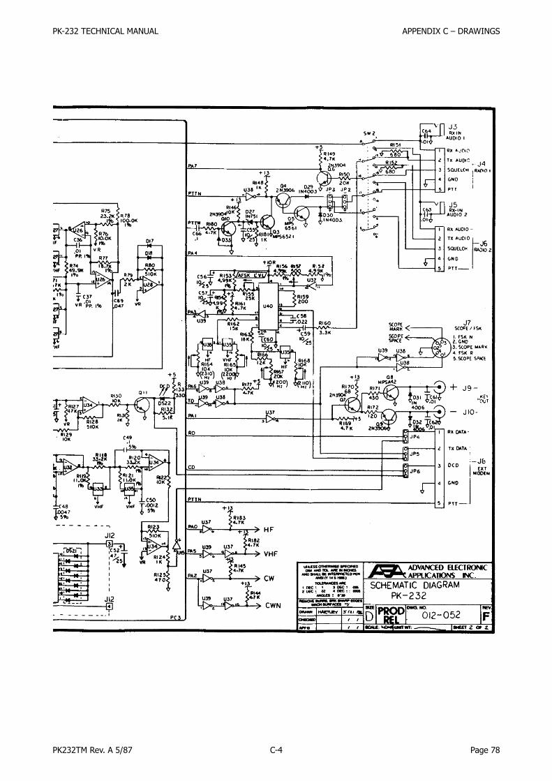
PK-232 TECHNICAL MANUAL APPENDIX C – DRAWINGS
PK232TM Rev. A 5/87 C-4 Page 78

PK-232 TECHNICAL MANUAL APPENDIX C – DRAWINGS
PK232TM Rev. A 5/87 C-5 Page 79

PK-232 TECHNICAL MANUAL APPENDIX C – DRAWINGS
PK232TM Rev. A 5/87 C-6 Page 80

PK-232 TECHNICAL MANUAL APPENDIX C – DRAWINGS
PK232TM Rev. A 5/87 C-7 Page 81

PK-232 TECHNICAL MANUAL APPENDIX D – Waveforms
PK232TM Rev. A 5/87 D-1 Page 82

PK-232 TECHNICAL MANUAL APPENDIX D – Waveforms
PK232TM Rev. A 5/87 D-2 Page 83
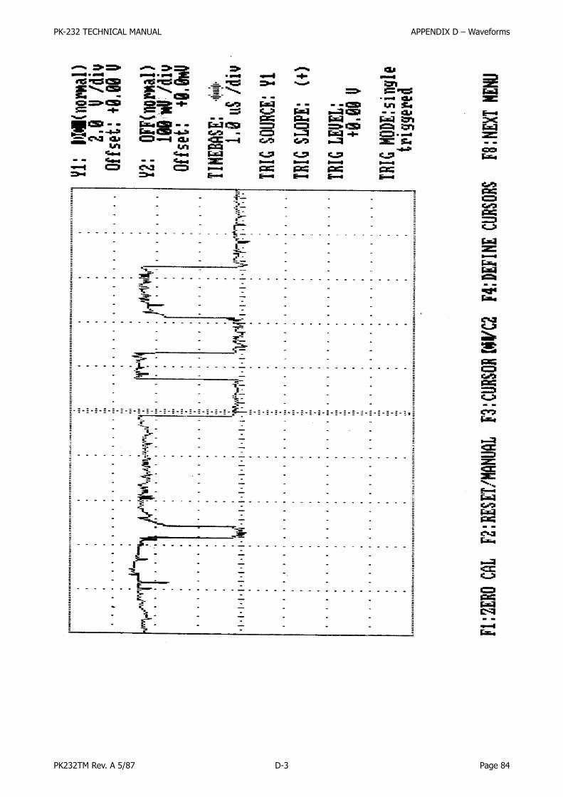
PK-232 TECHNICAL MANUAL APPENDIX D – Waveforms
PK232TM Rev. A 5/87 D-3 Page 84

PK-232 TECHNICAL MANUAL APPENDIX D – Waveforms
PK232TM Rev. A 5/87 D-4 Page 85

PK-232 TECHNICAL MANUAL APPENDIX D – Waveforms
PK232TM Rev. A 5/87 D-5 Page 86

PK-232 TECHNICAL MANUAL APPENDIX D – Waveforms
PK232TM Rev. A 5/87 D-6 Page 87

PK-232 TECHNICAL MANUAL APPENDIX D – Waveforms
PK232TM Rev. A 5/87 D-7 Page 88

PK-232 TECHNICAL MANUAL APPENDIX D – Waveforms
PK232TM Rev. A 5/87 D-8 Page 89
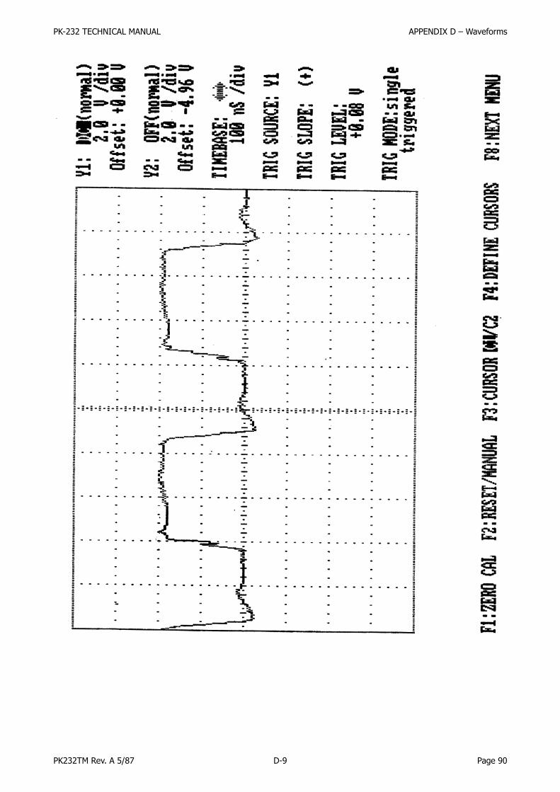
PK-232 TECHNICAL MANUAL APPENDIX D – Waveforms
PK232TM Rev. A 5/87 D-9 Page 90

PK-232 TECHNICAL MANUAL APPENDIX D – Waveforms
PK232TM Rev. A 5/87 D-10 Page 91

PK-232 TECHNICAL MANUAL APPENDIX D – Waveforms
PK232TM Rev. A 5/87 D-11 Page 92

PK-232 TECHNICAL MANUAL APPENDIX D – Waveforms
PK232TM Rev. A 5/87 D-12 Page 93

PK-232 TECHNICAL MANUAL APPENDIX D – Waveforms
PK232TM Rev. A 5/87 D-13 Page 94

PK-232 TECHNICAL MANUAL APPENDIX D – Waveforms
PK232TM Rev. A 5/87 D-14 Page 95

PK-232 TECHNICAL MANUAL APPENDIX D – Waveforms
PK232TM Rev. A 5/87 D-15 Page 96

PK-232 TECHNICAL MANUAL APPENDIX D – Waveforms
PK232TM Rev. A 5/87 D-16 Page 97

PK-232 TECHNICAL MANUAL APPENDIX D – Waveforms
PK232TM Rev. A 5/87 D-17 Page 98

PK-232 TECHNICAL MANUAL APPENDIX D – Waveforms
PK232TM Rev. A 5/87 D-18 Page 99

PK-232 TECHNICAL MANUAL APPENDIX D – Waveforms
PK232TM Rev. A 5/87 D-19 Page 100
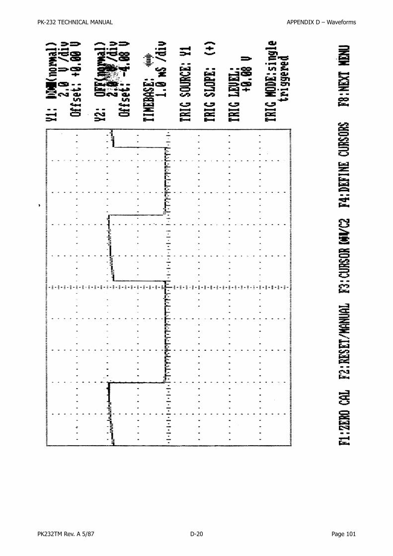
PK-232 TECHNICAL MANUAL APPENDIX D – Waveforms
PK232TM Rev. A 5/87 D-20 Page 101