aeronautical related applications using atn and tcp/ip
TRANSCRIPT

NASA / CR--2000-209922
Aeronautical Related Applications Using
ATN and TCP/IP Research Report
C. Dhas, T. Mulkerin, C. Wargo, R. Nielsen, and T. Gaughan
Computer Networks and Software, Inc., Springfield, Virginia
April 2000
The NASA STI Program Office... in Profile
Since its founding, NASA has been dedicated tothe advancement of aeronautics and spacescience. The NASA Scientific and Technical
Information (STI) Program Office plays a key part
in helping NASA maintain this important role.
The NASA STI Program Office is operated by .,,Langley Research Center, the Lead Center forNASA's scientific and technical information. The
NASA STI Program Office provides access to the
NASA STI Database, the largest collection ofaeronautical and space science STI in the world.
The Program Office is also NASA's institutional
mechanism for disseminating the results of itsresearch and development activities. These results
are published by NASA in the NASA STI ReportSeries, which includes the following report types:
TECHNICAL PUBLICATION. Reports of
completed research or a major significant
phase of research that present the results ofNASA programs and include extensive data
or theoretical analysis. Includes compilationsof significant scientific and technical data and
information deemed to be of continuing
reference value. NASA's counterpart of peer-reviewed formal professional papers but
has less stringent limitations on manuscriptlength and extent of graphic presentations.
TECHNICAL MEMORANDUM. Scientific
and technical findings that are preliminary or
of specialized interest, e.g., quick releasereports, working papers, and bibliographiesthat contain minimal annotation. Does not
contain extensive analysis.
CONTRACTOR REPORT. Scientific and
technical findings by NASA-sponsored
contractors and grantees.
CONFERENCE PUBLICATION. Collected
papers from scientific and technical
conferences, symposia, seminars, or other
meetings sponsored or cosponsored byNASA.
SPECIAL PUBLICATION. Scientific,
technical, or historical information from
NASA programs, projects, and missions,
often concerned with subjects having
substantial public interest.
TECHNICAL TRANSLATION. English-language translations of foreign scientific
and technical material pertinent to NASA'smission.
Specialized services that complement the STI
Program Office's diverse offerings includecreating custom thesauri, building customized
data bases, organizing and publishing researchresults.., even providing videos.
For more information about the NASA STI
Program Office, see the following:
• Access the NASA STI Program Home Page
at http://www.sti.nasa.gov
• E-mail your question via the Internet to
• Fax your question to the NASA AccessHelp Desk at (301) 621-0134
• Telephone the NASA Access Help Desk at(301) 621-0390
Write to:
NASA Access Help Desk
NASA Center for AeroSpace Information7121 Standard Drive
Hanover, MD 21076

NASA / CR--2000-209922
Aeronautical Related Applications
ATN and TCP/IP Research Report
Using
C. Dhas, T. Mulkerin, C. Wargo, R. Nielsen, and T. Gaughan
Computer Networks and Software, Inc., Springfield, Virginia
Prepared under Contract NAS3-99165, Task Order 2
National Aeronautics and
Space Administration
Glenn Research Center
April 2000

NASA Center for Aerospace Information7121 Standard Drive
Hanover, MD 21076
Price Code: A09
Available from
National Technical Information Service
5285 Port Royal Road
Springfield, VA 22100Price Code: A09

Table of Contents
Section Page
EXECUTIVE SUMMARY ....................................................................................................... 1
1. INTRODUCTION ............................................................................................................ 3
1.1. Purpose .......................................................................................................................... 3
1.2. Project Description ........................................................................................................ 3
1.3. Report Organization ..................................................................................................... 3
2. PROTOCOLS AND PROTOCOL ARCHITECTURES ............................................... 4
2.1. OSI Reference Model .................................................................................................... 4
2.1.1. Application Layer (Layer 7) .................................................................................... 5
2.1.2. Presentation Layer (Layer 6) .................................................................................... 5
2.1.3. Session Layer (Layer 5) ........................................................................................... 6
2.1.4. Transport Layer (Layer 4) ........................................................................................ 6
2.1.5. Network Layer (Layer 3) ......................................................................................... 6
2.1.6. Link Layer (Layer 2) ............................................................................................... 6
2.1.7. Physical Layer (Layer 1) .......................................................................................... 72.2. Attributes for an Aeronautical Internet ....................................................................... 7
2.2.1. High Availability ..................................................................................................... 72.2.2. Mobile Communications ......................................................................................... 7
2.2.3. Message Prioritization ............................................................................................. 7
2.2.4. Policy-based Routing ............................................................................................... 72.3. ACARS Protocol Overview ........................................................................................... 8
2.3.1. Technical Overview of ACARS ............................................................................... 8
2.3.2. General Format of ACARS Message ....................................................................... 8
2.3.3. ACARS Routing .................................................................................................... 10
2.3.4. ACARS Addressing ............................................................................................... 11
2.3.5. ACARS Security ................................................................................................... 12
2.3.6. ACARS Quality of Service .................................................................................... 12
2.3.7. ACARS Mobility .................................................................................................... 12
2.4. Aeronautical Telecommunications Network (ATN) .................................................. 13
2.4.1. Operational Benefits .............................................................................................. 13
2.4.2. ATN Concept ........................................................................................................ 14
2.4.3. ATNInfrastructure ................................................................................................ 15
2.4.4. Application Layer .................................................................................................. 16
2.4.5. Upper Layer Communications Services (ULCS) .................................................... 16
2.4.5.1. Presentation Layer ........................................................................................... 16
2.4.5.2. Session Layer Functionality ............................................................................ 17
2.4.6. Names and Addresses ............................................................................................ 19
2.4.7. Name Allocation Principles ................................................................................... 20
2.4.8. Responsibilities of Administrations ....................................................................... 20
2.4.9. Naming and Addressing Domains .......................................................................... 21
2.4.10. Upper Layer and Application Elements ................................................................. 22
NASA/CR--2000-209922 v

Table of Contents
Section Page
2.4.11. Internet Communication Services (ICS) ................................................................. 23
2.4.12. ATN Transport Layer ............................................................................................ 24
2.4.13. ATN Network Layer .............................................................................................. 24
2.4.14. Subnetwork Independent Role ............................................................................... 25
2.4.15. ISO/IEC 8473 Connectionless Network Protocol (CLNP) ..................................... 262.4.16. Connectionless Network Protocol Header Format .................................................. 26
2.4.17. ATN Addressing ................................................................................................... 28
2.4.18, ATN Routing Protocols ......................................................................................... 3 l
2.4. ! 9. ATN Routing ......................................................................................................... 31
2.4.19.1. End System-to-Intermediate System (ES-IS) ................................................... 32
2.4.19.2. Intermediate System-to-Intermediate System (IS-IS) ....................................... 32
2.4.19,3. Inter-Domain Routing Protocol (IDRP) ........................................................... 32
2.4.20. Use of Policy Based Routing by Organizations ...................................................... 33
2.4.21. Mobile Users ......................................................................................................... 34
2.4.21.1. Route Initiation ............................................................................................... 35
2.4.21.2. Routing Control .............................................................................................. 35
2.4.22. ATN Security ........................................................................................................ 36
2.4.23. ATN Mobility ........................................................................................................ 37
2.4.24. ATN Quality of Service (QoS) .............................................................................. 37
2.5. IPv4 Protocol Overview .............................................................................................. 39
2.5.1. ARPANET to NSFNET to Internet ........................................................................ 40
2.5.2. TCP/IPv4 Transport Layer ..................................................................................... 412.5.2.1. Reliable Communication ................................................................................ 41
2.5.2.2. Connection Establishment and Clearing .......................................................... 412.5.2.3. Data Communication ...................................................................................... 41
2.5.2.4. Functional Specification .................................................................................. 42
2.5.2.5. Precedence and Security .................................................................................. 44
2.5.3. IPv4Network Layer .............................................................................................. 452.5.4. IPv4 Header Format .............................................................................................. 45
2.5.5. IPv4 Addressing .................................................................................................... 502.5.5.1. IP Address Format .......................................................................................... 51
2.5.5.2. IP Address Classes ......................................................................................... 51
2.5.5.3. IP Subnet Addressing ...................................................................................... 52
2.5.6. IPv4 Routing ......................................................................................................... 52
2.5.6. I. Open Shortest Path First (OSPF) ..................................................................... 52
2.5.6.2. Routing Information Protocol (RIP) ................................................................ 53
2.5.6.3. Border Gateway Protocol (BGP) ..................................................................... 54
2.5.7. IPv4 & IPv6 Security (IPSec) ................................................................................ 54
2.5.7.1. Internet Key Exchange Security Protocol (IKE) .............................................. 55
2.5.7.2. IP Authentication Header (AH) ....................................................................... 55
2.5.7.3. IP Encapsulating Security Payload (ESP) ........................................................ 55
NASA/CR--2000- 209922 vi
Table of Contents
Section Page
1
2.5.7.4. Combining Security Mechanisms .................................................................... 56
2.5.8. IPv4 & IPv6 Mobility (Mobile IP) ......................................................................... 56
2.5.9. IPv4 and IPv6 QoS ................................................................................................ 57
2.5.9.1. QoS Signaling ................................................................................................. 57
2.5.9.2. IP Precedence: Signaling Differentiated QoS .................................................. 58
2.5.9.3. Guaranteeing QoS ........................................................................................... 582.6. IPv6 Protocol Overview .............................................................................................. 59
2.6.1. Header Format Simplification ................................................................................ 60
2.6.2. IPv6 Transport Layer ............................................................................................. 60
2.6.3. IPv6Network Layer .............................................................................................. 60
2.6.4. IPv6 Header Format .............................................................................................. 61
2.6.5. IPv6 Extension Headers ......................................................................................... 61
2.6.6. IPv6 Routing Protocols .......................................................................................... 63
2.6.7. IPv6 Addressing .................................................................................................... 63
2.6.8. IPv6 Routing ......................................................................................................... 65
2.6.9. IPv6 and NSAP addresses ...................................................................................... 66
2.7. ATN and TCPflP Architecture and Protocol Comparison ........................................ 66
2.7.1. ATN and TCP/IP Protocol Architecture ................................................................. 67
2.7.2. Transport Service .................................................................................................. 68
2.7.3. ATN Connection Oriented Transport Protocol ....................................................... 68
2.7.4. TCP/IP Reliable Stream Service ............................................................................ 69
2.7.5. TP4 and TCP Transport Services ........................................................................... 69
2.8. Network Service .......................................................................................................... 70
2.8.1. Routing ................................................................................................................. 71
2.8.1.1. End System to Intermediate System Routing ................................................... 72
2.8.1.2. Intradomain Intermediate System to Intermediate System Routing .................. 72
2.8.1.3. Interdomain Intermediate System to Intermediate System Routing .................. 73
2.8.2. TCP/IP Routing architecture .................................................................................. 73
2.8.2.1. Comparison of Discovery Protocols ................................................................ 73
2.8.2.2. Intradomain Routing ....................................................................................... 74
2.8.2.3. Interdomain Routing ....................................................................................... 75
2.8.3. Addressing ............................................................................................................ 762.8.4. Subnetwork ........................................................................................................... 76
REVIEW OF AERONAUTICAL RELATED APPLICATIONS ................................ 77
3ol °
3.3.
3.
3.
3.3.
Air Traffic Management (ATM) Applications ........................................................... 77
1.1. Predeparture Clearance (PDC) ............................................................................... 771.2. Taxi Clearance ...................................................................................................... 79
1.3. Context Management (CM) ................................................................................... 80
1.4. Controller Pilot Data Link Communication (CPDLC) ............................................ 81
1.5. Automatic Dependent Surveillance (ADS) ............................................................. 83
1.6. Automatic Dependent Surveillance Broadcast (ADS-B) ........................................ 84
NASA/CR--2000-209922 vii

Section
Table of Contents
Page
.
,
3.
3.
3.
3.
3.
3.2.
3.1.7.
3.1.8.
3.1.9.
3.1 10.
3.1 ll.
3.1 12.
3.1 13.
3.1 14.
3.1 15.
3.1.1
3.1.1
3.1.1
1.16.
1.17.
1.18.
1.19.
1.20.
Waypoint Position Reporting (WPT/POS) ............................................................. 85
Emergency Messages ............................................................................................ 86
Future Air Navigation System (FANS) .................................................................. 87Oceanic Clearance ................................................................................................. 87
Future Free Flight .................................................................................................. 89
Flight Information Services (FIS) .......................................................................... 90
Airport Terminal Information Service (ATIS) ........................................................ 92
Digital Airport Terminal Information Service (DATIS) ......................................... 94
Flight Information Services Broadcast (FIS-B) ...................................................... 94
5.1' Operational Applications ........................................... ., .................................... 95
5.2. Air Carriers and Business Operators ................................................................ 96
5.3. General Aviation ............................................................................................. 96
Notice to Airmen (NOTAM) ................................................................................. 97
International Aviation Routine Weather Report (METAR) .................................... 99
Terminal Weather Information to Pilots (TWIP) .................................................. 100
Wide Area Augmentation System (WAAS) ......................................................... 101
Local Area Augmentation System (LAAS) .......................................................... 102
1.21. Cockpit Voice ...................................................................................................... 103
Airline Operational Communications (AOC) .......................................................... 104
3.2.1. Data Link Related System Control, Peripherals, and Subsystems ......................... 105
3.2.2. Flight Operations ................................................................................................. 110
3.2.3. Maintenance Operations ...................................................................................... 113
3.2.4. Airport/Ramp Area Operations ............................................................................ 113
3.2.5. Cockpit Voice Operations (Company) ................................................................. 114
3.2.6. AOC Communications Requirement Parameters .................................................. 114
3.3. Airline Administrative Communication ................................................................... 115
3.4. Airline Passenger Communications .......................................................................... 116
3.4.1. Telephony ........................................................................................................... 1163.4.2. E-Mail ................................................................................................................. 116
3.4.3. Internet Services .................................................................................................. 117
3.4.4. Facsimile ............................................................................................................. 118
3.5. Entertainment ........................................................................................................... 119
3.5.1. Games ................................................................................................................. 119
3.5,2. Movies/Videos .................................................................................................... 119
3.5.3. Gambling ............................................................................................................ 120
3.5.4. Shopping ............................................................................................................. 1203.5.5. Automated Teller Machines .................................................................................. 121
PROTOCOLS�APPLICATIONS COMPARISON .................................................... 123
4.1. Communications Requirements Sets ........................................................................ 123
4.2. Allocation of Applications to Requirements Sets ..................................................... 123
4.3. Broadcast Requirements Set ..................................................................................... 125
NASA/CR--2000-209922 viii

Table of Contents
Section Page
4,4,
4.4.1.
4.4.2.
4.4.3.
4.4.4.
4.4.5.
Unicast Requirements Sets ........................................................................................ 127
Unicast Requirements Set 1 - Flight Safety Messages ......................................... 127
Unicast Requirements Set 2 - Operational/Administrative Messages ................... 128
Unicast Requirements Set 3 - Bulk Data/Streaming Video Services .................... 129
Unicast Requirements Set 4 - Flight Safety Digitized Voice ................................ 130
Unicast Requirements Set 5 - Operational/Administrative Digitized Voice ......... 131
4.5. Why Transition to IPv6 - What is Wrong with IPv4? ............................................. 1324.6. Network Address Translation ................................................................................... 133
4.7. Protocols/Applications Comparison Conclusions .................................................... 134
5. TRENDS FOR THE FUTURE .................................................................................... 136
5.1. Achieving Agreement in Regulatory and Standards Bodies .................................... 136
5.2. Industry Capital Investment .......................................................... , ........................... 137
5.3. Trends in Adopting Technology ............................................................................... 1395.4. Trends In Global Communications .......................................................................... 144
5.4.1. Communications Infrastructure ............................................................................ 144
5.4.1.1. Teledensity .................................................................................................... 146
5.4.1.2. Cellular Telephone Capacity ......................................................................... 146
5.4.1.3. Satellite Communications .............................................................................. 146
5.4.2. Socioeconomic Changes ...................................................................................... 1475.4.2.1. Privatization .................................................................................................. 147
5.4.2.2. Electronic Commerce .................................................................................... 148
5.4.2.3. Declining Costs for Implementing High-Capacity Global Infrastructure ........ 148
5.4.3. Technological Indicators ...................................................................................... 148
5.4.3.1. Changing Service Offerings .......................................................................... 148
5.4.3.2. Improved Capacity Utilization Techniques .................................................... 148
5.4.3.3. Technology Growth Areas ............................................................................ 150
5.5. Implications for the Future of Aeronautical Related Applications ......................... 150
5.6. Note for Future Research .......................................................................................... 151
6. CONCLUSIONS ................................. . ,, .... , .............................................................. ... 152
APPENDIX A. ACRONYMS .............................................................................................. A-1
APPENDIX B. CPDLC MESSAGES .................................................................................. B-I
NASA/CR--2000-209922 ix
Figure
List of Figures
Page
Figure 2-1.
Figure 2-2.
Figure
Figure
Figure
Figure
Figure
Figure
Figure
Figure
Figure
Figure
Figure 2-13.
Figure 2-14.
Figure 2-15.
Figure 2-16.
Figure 5-1.
Figure 5-2.
Figure 5-3.
Protocol Stack Comparisons .................................................................................... 4
OSI Seven (7) Layer Protocol Reference Model ....................................................... 5
2-3. Simplified Diagram of ACARS Routing ................................................................ 11
2-4. ATN Network Components ................................................................................... 16
2-5. ATN Transport Service Access Point (TSAP) Address .......................................... 20
2-6. CLNP Header ........................................................................................................ 26
2-7. ATN Address Structure .......................................................................................... 28
2-8. Simplified View of ATN Routing .......................................................................... 31
2-9. TCP Header Format ............................................................................................... 42
2-10. IPv4 Header ......................................................................................................... 46
2-11. IPv4 Address Classes ........................................................................................... 51
2-12. IPv6 Header ......................................................................................................... 61
Three Examples of IPv6 Packets with Extension Headers .................................... 62
IPv6 Aggregatable Global Unicast Address Format ............................................. 64
ATN Protocol Architecture ........................... 66
ATN and TCP_P Architecture ............................................................................. 67
Global Communications Infrastructure Growth Trends ........................................ 145
Global Teledensity ............................................................................................... 146
Internet Host Growth Trends ................................................................. 149
NASA/CR--2000-209922 x
Table
List of Tables
Page
Table 2-1.
Table 2-2.
Table 2-3.
Table 2-4.
Table 2-5.
Table 2-6.
Table 2-7.
Table 2-8.
Table 2-9.
Table 3-1.
Table 3-2.
Table 3-3.
Table 3-4.
Table 3-5.
Table 3-6.
Table 3-7.
Table 3-8.
Table 3-9.
Table 3-10.
Table 3-11.
Table 3-12.
Table 3-13.
Table 3-14.
Table 3-15.
Table 3-16.
Table 3-17.
Table 3-18.
Table 3-19.
Table 3-20.
General Format of an ACARS Message .................................................................... 9
Standard Message Identifier (SMI) Examples ......................................................... 10
ATN Address Fields Sizes ...................................................................................... 29
Version (VER) Field Values ................................................................................... 30
ICAO Regional Identifiers ...................................................................................... 30
TCP Options ........................................................................................................... 44
IPv4 Header Internet Options .................................................................................. 49
Comparison of TCP and TP4 Functions .................................................................. 70
Comparison of CLNP and IP Functions ................................................................... 71
PDC Communications Characteristics ..................................................................... 78
PDC Information Unit Size ..................................................................................... 79
PDC Occurrence ..................................................................................................... 79
Taxi Clearance Communications Characteristics ..... , ............................................... 79
CM Communications Characteristics ...................................................................... 80
CPDLC Communications Characteristics ................................................................ 82
CPDLC Message Size ............................................................................................. 82
CPDLC Message Frequency ................................................................................... 82
ADS Communications Characteristics ..................................................................... 84
ADS-B Communications Characteristics ............................................................... 85
WPT/POS Communications Characteristics .......................................................... 86
Emergency Messages Communications Characteristics ......................................... 86
FANS Communications Characteristics ................................................................. 87
Oceanic Clearance Communications Characteristics ............................................. 88
Free Flight Communications Characteristics ......................................................... 90
FIS Communications Characteristics ..................................................................... 92
FIS Message Size .................................................................................................. 92
FIS Message Frequency ........................................................................................ 92
ATIS Communications Characteristics .................................................................. 93
DATIS Communications Characteristics ............................................................... 94
NASA/CR--2000-209922 xi
Table
List of Tables
Page
Table 3-21.
Table 3-22.
Table 3-23.
Table 3-24.
Table 3-25.
Table 3-26.
Table 3-27.
FIS-B Communications Characteristics ................................................................. 97
NOTAM Communications Characteristics ............................................................ 99
METAR Communications Characteristics ........................................................... 100
TWIP Communications Characteristics ................................................................ 101
WAAS Communications Characteristics ............................................................. 102
LAAS Communications Characteristics .............................................................. 103
Cockpit Voice Communications Characteristics .................................................. 104
Table 3-28. Data Link Messages Related to Systems Control, Peripheral Communications, and
Subsystem Control .......................................................................................................... 105
Table 3-29.
Table 3-30.
Table 3-31.
Table 3-32.
Table 3-33.
Table 3-34.
Table 3-35.
Table 3-36.
Table 3-37.
Table 3-38.
Table 3-39.
Table 3-40.
Table 3-41.
Table 4-1.
Table 4-2.
Table 4-3.
Table 4-4.
Table 4-5.
Table 4-6.
Table 4-7.
Messages Related to Flight Operations Applications ........................................... I 10
Messages Related to Aircraft Maintenance .......................................................... 113
AOC Communications Characteristics ................................................................ 114
AAC Communications Characteristics ................................................................ 116
Telephony Communications Characteristics ........................................................ 117
E-Mail Communications Characteristics ............................................................. 117
Internet Services Communications Characteristics .............................................. 1 ! 8
Facsimile Communications Characteristics ......................................................... 118
Games Communications Characteristics .............................................................. 119
Movies/Videos Communications Characteristics ................................................. 120
Gambling Communications Characteristics ......................................................... 120
Shopping Communications Characteristics .......................................................... 121
Automated Teller Machines Communications Characteristics ............................. 122
Applications Grouped into Requirements Sets ....................................................... 124
Broadcast Applications ......................................................................................... 126
Broadcast Requirements Set Parameters ................................................................ 126
Unicast Set 1 - Flight Safety Messages .................................................................. 127
Protocols Supporting Unicast Set 1 Applications ................................................... 128
Unicast Set 2- Operational/Administrative Messages ........................................... 128
Protocols Supporting Unicast Set 2 Applications ................................................... 129
NASA/CR--2000-209922 xii

Table
List of Tables
Page
Table 4-8.
Table 4-9.
Table 4-10.
Table 4-11.
Table 4-12.
Table 4-13.
Table 5-1.
Table B- 1.
Table B-2.
Unicast Set 3 - Bulk Data/Streaming Video Services ............................................. 130
Protocols Supporting Unicast Set 3 Applications ................................................... 130
Unicast Set 4 - Flight Safety Digitized Voice ...................................................... 131
Protocols Supporting Unicast Set 4 Applications ................................................. 131
Unicast Set 5 - Operational/Administrative Digitized Voice ................................ 132
Protocols Supporting Unicast Set 5 Applications ................................................. 132
Investment to Achieve Global Interoperability ...................................................... 139
CPDLC Uplink Messages ..................................................................................... B-1
CPDLC Downlink Messages .............................................................................. B- 10
NASA/CR--2000-209922 xiii

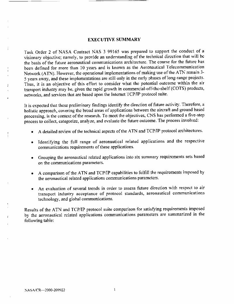
EXECUTIVE SUMMARY
Task Order 2 of NASA Contract NAS 3 99165 was prepared to support the conduct of a
visionary objective; namely, to provide an understanding of the technical direction that will be
the basis of the future aeronautical communications architecture. The course for the future has
been defined for more than 10 years and is known as the Aeronautical Telecommunication
Network (ATN). However, the operational implementations of making use of the ATN remain 3-
5 years away, and these implementations are still only in the early phases of long-range projects.
Thus, it is an objective of this effort to consider what the potential outcome within the air
transport industry may be, given the rapid growth in commercial-off-the-shelf (COTS) products,
networks, and services that are based upon the Internet TCP/IP protocol suite.
It is expected that these preliminary findings identify the direction of future activity. Therefore, a
holistic approach, covering the broad areas of applications between the aircraft and ground based
processing, is the context of the research. To meet the objectives, CNS has performed a five-step
process to collect, categorize, analyze, and evaluate the future outcome. The process involved:
• A detailed review of the technical aspects of the ATN and TCP/IP protocol architectures.
• Identifying the full range of aeronautical related applications and the respective
communications requirements of these applications.
• Grouping the aeronautical related applications into six summary requirements sets based
on the communications parameters.
• A comparison of the ATN and TCP/IP capabilities to fulfill the requirements imposed by
the aeronautical related applications communications parameters.
• An evaluation of several trends in order to assess future direction with respect to air
transport industry acceptance of protocol standards, aeronautical communications
technology, and global communications.
Results of the ATN and TCP/IP protocol suite comparison for satisfying requirements imposed
by the aeronautical related applications communications parameters are summarized in the
following table:
NASA/CR--2000-209922 I
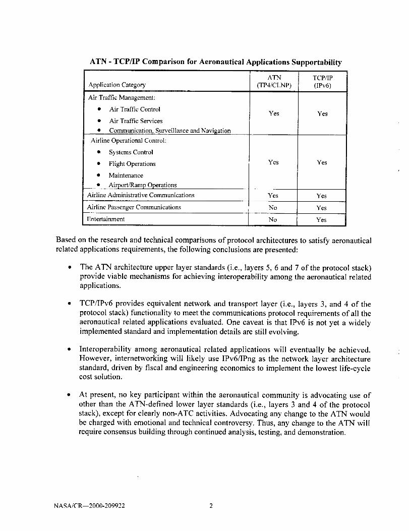
ATN - TCP/IP Comparison for Aeronautical Applications Supportability
ATN TCP/IPApplication Category (TP4/CLNP) (IPv6)
Air Traffic Management:
• Air Traffic Control
• Air Traffic Sen'ices
• Communication_,S_urveillance and Navigation
Airline Operational Control:
• Systems Control
• Flight Operations
• Maintenance
• Airport/Ramp Operations
Airline Administrative Communications
Airline Passenger Communications
Entertainment
Yes Yes
Yes Yes
Yes Yes
No Yes
No Yes
Based on the research and technical comparisons of protocol architectures to satisfy aeronautical
related applications requirements, the following conclusions are presented:
The ATN architecture upper layer standards (i.e., layers 5, 6 and 7 of the protocol stack)
provide viable mechanisms for achieving interoperability among the aeronautical related
applications.
TCP/IPv6 provides equivalent network and transport layer (i.e., layers 3, and 4 of the
protocol stack) functionality to meet the communications protocol requirements of all the
aeronautical related applications evaluated. One caveat is that IPv6 is not yet a widely
implemented standard and implementation details are still evolving.
Interoperability among aeronautical related applications will eventually be achieved.
However, internetworking will likely use IPv6/IPng as the network layer architecture
standard, driven by fiscal and engineering economics to implement the lowest life-cyclecost solution.
At present, no key participant within the aeronautical community is advocating use of
other than the ATN-defined lower layer standards (i.e., layers 3 and 4 of the protocol
stack), except for clearly non-ATC activities. Advocating any change to the ATN would
be charged with emotional and technical controversy. Thus, any change to the ATN will
require consensus building through continued analysis, testing, and demonstration.
NASA/CR--2000-209922 2

1. INTRODUCTION
1.1. Purpose
This report provides the results of the Aeronautical Related Applications using ATN and TCP/IP
research study. It is a deliverable under Task Order 2 of NASA Contract No. NAS 3 99165.
1.2. Project Description
The NASA Glenn Research Center (GRC) requires that the AC/ATM project evaluate the
application of the existing Transmission Control Protocol (TCP) and Internet Protocol (IP) for
use as a viable, inexpensive alternative to the implementation of the International Civil Aviation
Organization (ICAO) Aeronautical Telecommunications Network (ATN) protocol. The GRC
goal is to identify an appropriate, readily available protocol to provide the earliest opportunity
for realizing the benefits of Free Flight. This report analyzes the suitability of the TCP/IP
functionality for ground and air entities usage as a replacement communication infrastructure. By
comparative analysis, the report evaluates whether TCP/IP has the capacity, efficiency, and
flexibility to provide ATN equivalent services.
1.3. Report Organization
The report starts with a review of internetworking protocols in relation to the OSI model
transport and network layers in Section 2 and a review of the aeronautical related applications
requirements in Section 3. Section 4, then, is a comparison of TCP/IP and the aeronautical
related applications requirements. Several trends are evaluated as indicators of the future in
Section 5. Based on the comparison of TCP_P and the aeronautical related applications
requirements combined with future trends, Section 6 provides a set of conclusions and
recommendations.
There are two appendices - Appendix A provides a list of acronyms and Appendix B contains the
list of Controller Pilot Data Link Communication (CPDLC) uplink and downlink messages.
NASA/CR--2000-209922 3

2. PROTOCOLS AND PROTOCOL ARCHITECTURES
This section provides an overview of the "Open Systems lnterconnection" (OSI) reference model
with a discussion of the network and transport layer communication protocols implemented for
the Aircraft Communications Addressing and Reporting System (ACARS), Aeronautical
Telecommunications Network (ATN), Internet Protocol Version 4 (IPv4), and Internet Protocol
Version (IPv6). Figure 2-1 contains a comparison of the various protocol stacks.'
ACARS ATN
CPDLC,ADS, FIS CPDLC, ADS, FIS
CQPP
OSIMODE L TCP/IPv4 TCP/IPv6
Application
Presentation
COSP Session
TP4, CLTP Transport ......... ! |
ACARS CLNP F i I[
Routing '" NetworkProtocols [SNDCF
FTPNFS
Telnet
SMTP XDRSNMP
RPC
FTPNFS
Telnet
SMTP XDRSNMP
RPC
TCP, UDP TCP, UDP
Pv4 IPv6
RoutingProtocols
RoutingProtocols
VDL Mode 2, 3, 4 Link
Not Mode S Not Specified Not SpecifiedSpecified SATCOM Physical
Aeronautical Protocols
K. Y K. d|,
Industry Standard Protocols
Figure 2-1. Protocol Stack Comparisons
2.1. OSIReference Model
The ATN network architecture is based on the International Standards Organization 0SO) "Open
Systems Interconnection (OSI) Information Processing Systems - Basic Reference Model". This
section presents a short introduction to the OSI Reference Model or "seven (7) layer protocol
stack" as it is commonly referred to in the industry. Figure 2-2 shows the relationships among
the layers specified in the OSI Reference Model.
NASA/CR--2000-209922 4

System A
Application
Presentation
Session
Transport
Network
Data Link
Physical
//
System B
Application
Presentation
Session
Transport
Network
Data Link
Physical
............................................................... L
Figure 2-2. OSI Seven (7) Layer Protocol Reference Model
2.1.1. Application Layer (Layer 7)
The application layer is the OSI layer closest to the user. It differs from the other layers in that it
does not provide services to any other OSI layer. Rather, it provides services to application
processes lying outside the scope of the OSI model. Examples of such application processes
include spreadsheet programs, word-processing programs, and banking terminal programs.
The application layer identifies and establishes the availability of intended communication
partners, synchronizes cooperating applications, and establishes agreement on procedures for
error recovery and control of data integrity. Also, the application layer determines whether
sufficient resources for the intended communication exist.
2.1.2. Presentation Layer (Layer 6)
The presentation layer ensures that information sent by the application layer of the source system
will be readable by the application layer of the destination system. If necessary, the presentation
layer translates between multiple data representation formats by using a common data
representation.
The presentation layer concerns itself not only with the format and representation of actual user
data, but also with the data structures used by programs. Therefore, in addition to actual data
format transformation (if necessary), the presentation layer negotiates the data transfer syntax for
the application layer.
NASA/CR--2000-209922 5

2.1.3. Session Layer (Layer 5)
As its name implies, the session layer establishes, manages, and terminates sessions between
applications. Sessions consist of a dialog between two or more presentation entities (recall that
the session layer provides its services to the presentation layer). The session layer synchronizes
the dialog between presentation layer entities and manages their data exchange. In addition to the
basic regulation of conversations (sessions), the session layer offers provisions for data
expedition, class of service, and exception reporting of session-layer, presentation-layer, and
application-layer problems.
2.1.4. Transport Layer (Layer 4)
The boundary between the session layer and the transport layer can be thought of as the
boundary between application-layer protocols and lower-layer protocols. Whereas the
application, presentation, and session layers are concerned with application issues, the lower four
layers are concerned with data transport issues.
The transport layer attempts to provide a data transport service that shields the upper layers from
transport implementation details. Specifically, issues such as how retiable is the transport service
over an inter-network are the concern of the transport layer. In providing reliable service, the
transport layer provides mechanisms for the establishment, maintenance, and orderly termination
of virtual circuits, fault detection and recovery, and information flow control (to prevent one
system from overrunning another).
2.1.5. Network Layer (Layer 3)
The network layer provides connectivity and path selection between two end systems that may
be located on geographically diverse subnetworks. A subnetwork, in this instance, is essentially a
single network cable (sometimes called a segment).
Because a substantial geographic distance and many subnetworks can separate two end systems
desiring communication, the network layer main function is routing. Routing protocols select
optimal paths through the series of interconnected subnetworks. Traditional network-layer
protocols then move information along these paths.
2.1.6. Link Layer (Layer 2)
The link layer (formally referred to as the data link layer) provides reliable transit of data across
a physical link. In so doing, the link layer is concerned with physical (as opposed to network or
logical) addressing, network topology, line discipline (how end systems will use the network
link), error notification, ordered delivery of frames, and flow control.
NASA/CR--2000-209922 6

2.1.7. Physical Layer (Layer 1)
The physical layer defines the electrical, mechanical, procedural, and functional specifications
for activating, maintaining, and deactivating the physical link between end systems. Such
characteristics as voltage levels, timing of voltage changes, physical data rates, maximum
transmission distances, physical connectors, and other, similar, attributes are defined by physical
layer specifications.
2.2. Attributes for an Aeronautical lnternet
The Internet is a "best effort" communications service. The end user really has little control over
the methods by which data is delivered, or for that matter the path through the Internet.
Aeronautical communications requires a level of Quality of Service (QoS), security, and
mobility. Some of the qualities needed for an Aeronautical Intemet include:
• High Availability
• Mobile Communications
• Message Prioritization
• Policy Based Routing
2.2.1. High Availability
An Aeronautical Internet should be designed to provide a high availability network by ensuring
that there is not a single point of failure. High availability can be supported by providing
multiple alternative routes to the same destination with dynamic switching between alternatives.
2.2.2. Mobile Communications
An Aeronautical Internet should fully support mobile communications over a wide variety ofmobile communications networks.
2.2.3. Message Prioritization
Data on an Aeronautical lnternet should be given a relative priority on the network in order to
ensure that low priority data does not impede the flow of high priority data. Advanced
congestion management techniques that "throttle back" low priority data when the network
comes closer to saturation ensure that high priority data always gets a low transit delay path.
2.2.4. Policy-based Routing
Aeronautical Internet routing procedures should support a wide range of organizational and
national policies, including the enforcing of restrictions on what types of traffic can pass over
both ground and air-ground data links, and control over which air-ground data link types are used
by which applications. Organizations that interconnect the networks are free to enforce routing
NASA/CR--2000-209922 7

policies that control the types of data being exchanged, and select whose data is allowed to be
routed through their networks.
2.3. ACARS Protocol Overview
ACARS stands for Aircraft Communications Addressing and Reporting System. This is an air -
ground - air radio data system, developed by Aeronautical Radio Inc. (ARINC) in the 1970's, for
digital commercial aircraft to ground communications. Data sensors on board the aircraft register
"events" which are fed into a computer to be converted into data packets to be sent to ground
stations via the aircraft's normal VHF voice radio. The receiving ground system routes the data
packets via ARINC's Electronic Switching System and central computer to the relevant carrier.
2.3.1. Technical Overview of ACARS
ACARS is an air-to-ground communications system that includes internetworking software
protocols. The primary sub-systems of ACARS include:
• Airborne Subsystem which consists of the:
- Management Unit (MU) receives ground-to-air messages via the VHF radio
transceiver, and also controls the replies.
- Control Unit (CU) is the air crew interface with the ACARS system, consisting of a
display screen and printer.
• Ground Subsystem which consists of all the ARINC ACARS remote transmitting /
receiving stations, and the ARINC computer and intemetworking systems.
Air Carrier C2 (Command and Control) and Management Subsystem which is basically
all the ground based airline operations such as operations control, maintenance, crew
scheduling and the like, linked up with the ACARS system.
• ACARS Messages that can be categorized in two ways:
- "Downlinks" which are those ACARS transmissions originating in the aircraft
- Uplinks are those messages sent from the ground station to the aircraft.
2.3.2. General Format of ACARS Message
ACARS is a character oriented internetworking system. All data is transmitted as ASCII
characters. Fields of a message are separated by "Line Feed" characters, unless otherwise
specified. Table 2-l shows the general format of an ACARS message.
NASA/CR--2000-209922 8

Line
1
2
3
4-m
m-n
Table 2-1. General Format of an
Contents
PriorityfDestination Address
Signature/Transmission time
Standard Message Identifier (SMI)
Text Elements
Free Text
ACARS Message
Example
QU ADRDPAL
DSPXXXX 121212
AGM
FI XX0001/AN N 123XX
UPLINK OR DOWNLINK
Line 1 - Priority/Destination Address
The Destination Address line (also known as simply the Address line) is composed of the
priority of the ground message and the address list of the intended recipients. The two-character
Priority identifier is used to indicate the priority of the message. There is only one priority code
in use; thus all messages are encoded with the characters 'QU'. This is followed by a SPACEand then the Destination Address list. Each address is 7 characters long. If more than one address
is included, they are separated by a SPACE. This line ends with a [CARRIAGE RETURN/LINE
FEED] <CR/LF>. The maximum number of addresses is 16.
Line 2 - Signature
Begins with the PERIOD character <.> and is followed by the address of the sender. After the
sender's address, it is possible to add a timestamp in the format ddhhmm (day/hour/minute). It is
possible to enter further signature information after the timestamp. This line ends with
[CARRIAGE RETURN/LINE FEED] <CR/LF>.
Line 3 - Standard Message Identifier (SMI)
Contains a three character code. The line terminator for the SMI line is a [CARRIAGE
RETURN/LINE FEED] <CR/LF> sequence. Table 2-2 shows SMI examples.
Line 4 - Text Element Field
The Text Element Field contains a series of text elements. Each text elements is composed of
three parts: Text Element Identifier (TEl), data, and a Text Element Terminator (TET). The first
text element is usually the Flight Identifier (FI). The FI is composed of a two character Airline
Identifier and a four character Flight Number.
NASA/CR--2000-209922 9
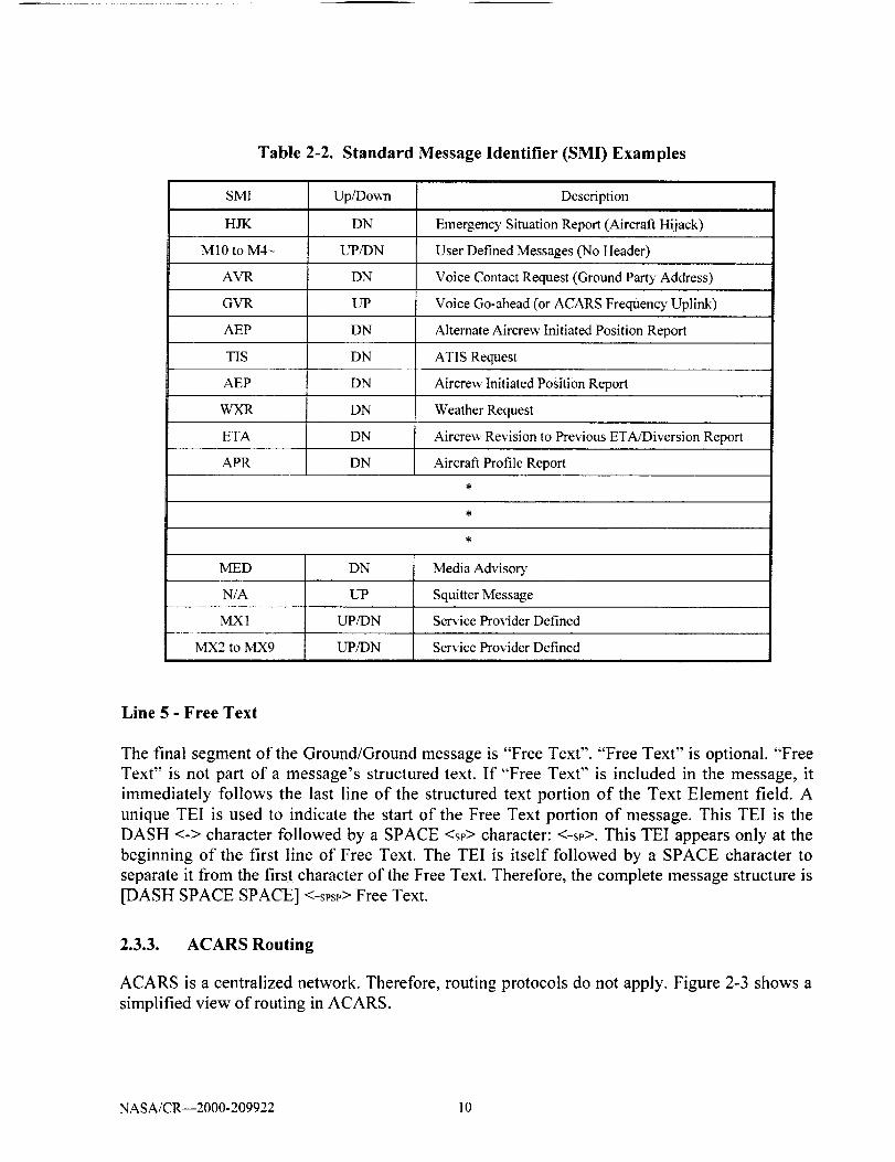
Table 2-2. Standard Message Identifier (SMI) Examples
SMI Up/Down Description
HJK DN Emergency Situation Report (Aircraft Hijack)
M10 to M4- UP/DN User Defined Messages (No Header)
AVR DN Voice Contact Request (Ground Party Address)
GVR UP Voice Go-ahead (or ACARS Frequency Uplink)
AEP DN Alternate Aircrew Initiated Position Report
TIS DN ATIS Request
AEP DN Aircrew Initiated Position Report
WXR DN Weather Request
ETA DN Aircrew Revision to Previous ETA/Diversion Report
APR DN Aircraft Profile Report
IVIED DN Media Advisor'
N/A UP Squitter Message
MX 1 UP/DN Service Provider Defined
MX2 to MX9 UP/DN Service Provider Defined
Line 5 - Free Text
The final segment of the Ground/Ground message is "Free Text". "Free Text" is optional. "Free
Text" is not part of a message's structured text. If "Free Text" is included in the message, it
immediately follows the last line of the structured text portion of the Text Element field. A
unique TEI is used to indicate the start of the Free Text portion of message. This TEI is the
DASH <-> character followed by a SPACE <sp> character: <-sp>. This TEI appears only at the
beginning of the first line of Free Text. The TEI is itself followed by a SPACE character to
separate it from the first character of the Free Text. Therefore, the complete message structure is
[DASH SPACE SPACE] <-sPsP> Free Text.
2.3.3. ACARS Routing
ACARS is a centralized network. Therefore, routing protocols do not apply. Figure 2-3 shows a
simplified view of routing in ACARS.
NASA/CR--2000-209922 10
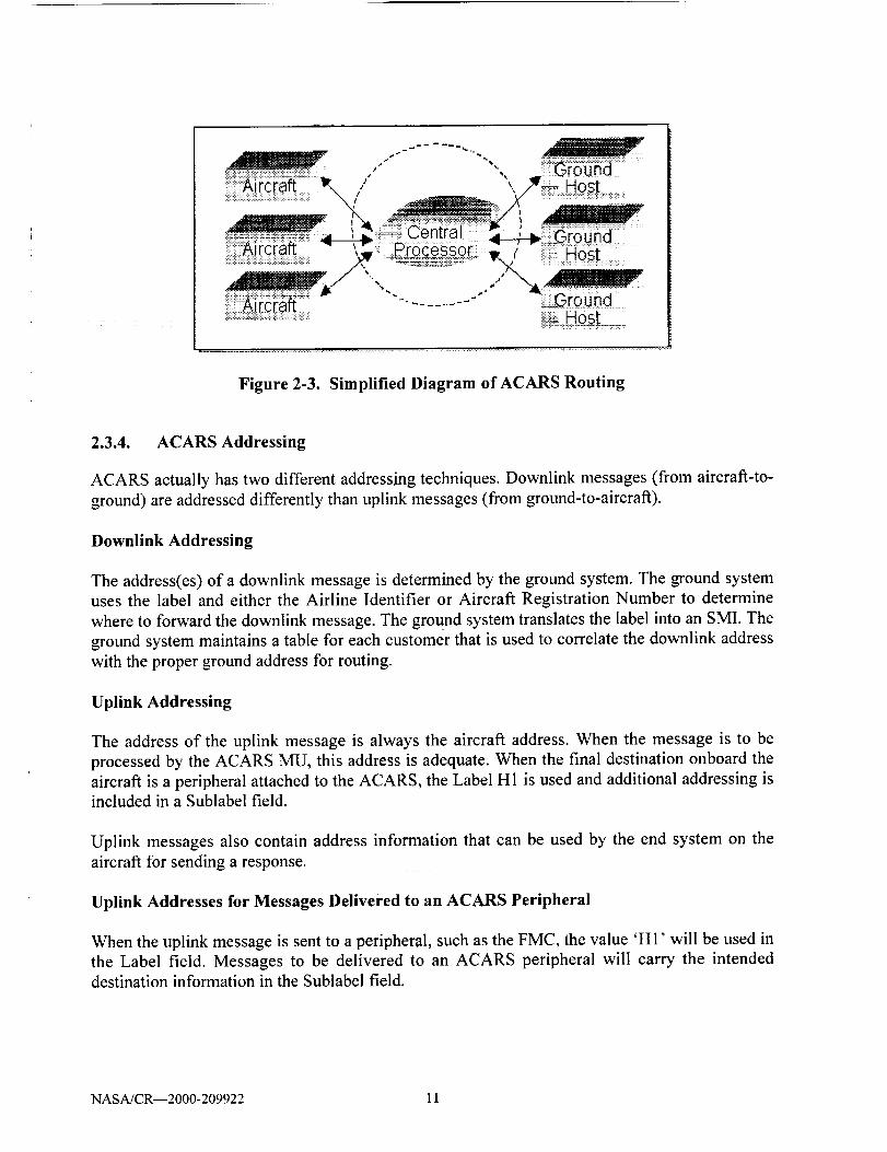
Figure 2-3. Simplified Diagram of ACARS Routing
2.3.4. ACARS Addressing
ACARS actually has two different addressing techniques. Downlink messages (from aircraft-to-
ground) are addressed differently than uplink messages (from ground-to-aircraft).
Downlink Addressing
The address(es) of a downlink message is determined by the ground system. The ground system
uses the label and either the Airline Identifier or Aircraft Registration Number to determine
where to forward the downlink message. The ground system translates the label into an SMI. The
ground system maintains a table for each customer that is used to correlate the downlink address
with the proper ground address for routing.
Uplink Addressing
The address of the uplink message is always the aircraft address. When the message is to be
processed by the ACARS MU, this address is adequate. When the final destination onboard the
aircraft is a peripheral attached to the ACARS, the Label H1 is used and additional addressing isincluded in a Sublabel field.
Uplink messages also contain address information that can be used by the end system on the
aircraft for sending a response.
Uplink Addresses for Messages Delivered to an ACARS Peripheral
When the uplink message is sent to a peripheral, such as the FMC, the value 'HI' will be used in
the Label field. Messages to be delivered to an ACARS peripheral will carry the intended
destination information in the Sublabel field.
NASA/CR--2000-209922 11
2.3.5. ACARS Security
ACARS provides relatively little security. Intemetworked sites use inexpensive, handheld radios
and a common PC interface to read ACARS messages. No inherent encryption or authentication
is built into the system.
2.3.6. ACARS Quality of Service
The only real-time Quality of Service (QoS) available from ACARS is the signal quality of the
air-to-ground physical link. This is a number representing the signal quality of the link. This QoS
should not be confused with network QoS. The ACARS system does not provide network-level
QoS. The ACARS system does provide post-processing statistics of network quality to its users.
This information varies by the network service provider.
2.3.7. ACARS Mobility
Mobility in ACARS system is simplified due to its centralized nature. All ACARS messages
pass through a central node (or central processor). The central node has the ability to track all
messages and determine where the aircraft is located at all times. The process by which mobility
in ACARS is implemented is quite simple and can be illustrated in the following steps:
* ACARS downlink (from aircraft to ground)
- An ACARS messages is received by a VHF, HF or SATCOM ground station.
- Upon receipt of the downlink, the ground station forwards the ACARS message to the
system central node for processing and routing.
- The central node, upon receiving the ACARS downlink, forwards the message to the
appropriate stationary end system.
* ACARS uplink (from ground to aircraft)
- An ACARS message transmitted from a stationary ground end-system is received bythe central node.
Upon receipt, the central node forwards the message to the appropriate ground station
for transmission. The central node chooses the ground station based on criteria such
as best signal quality or other determining factors.
- The ground station, upon receiving an uplink message from the central node transmits
the message to the aircraft.
NASA/CR--2000-209922 12
2.4. Aeronautical Telecommunications Network (ATN)
In the early 1980s, the international civil aviation community started to express concern about
the limitations of existing facilities and procedures and their inability to cope with increasing air
traffic in future years. Therefore, a Special Committee on Future Air Navigation Systems
(FANS) was established by the ICAO Council in 1983. Its purpose was to study, identify and
assess new concepts and new technology in the field of air navigation, including satellite
technology and to make recommendations for the development of air navigation for intemational
civil aviation.
A major result of the work of the FANS Committee was the global communications, navigation,and surveillance/air traffic management (CNS/ATM) systems concept that identified the use of
data communications and of satellite-based systems as being the two major areas of
improvement to the existing systems. The global CNS/ATM systems concept was consequently
endorsed by the Tenth Air Navigation Conference in 1991. The systems concept was further
developed and refined by the Phase II of the FANS Committee that concluded its work in 1993.
Furthermore, noting the fact that some implementation activities had begun, the name "global
CNS/ATM systems concept" was changed to "CNS/ATM systems". The aeronautical
telecommunication network (ATN) is an integral part of the CNS/ATM systems.
ATN comprises application entities and communication services that allow ground, air-to-
ground, and avionics data subnetworks to interoperate. This is achieved by using common
interfaces, services, and protocols based on international standards. ATN has been specified to
provide data communications services to Air Traffic Service (ATS) provider organizations and
Aircraft Operating agencies for the following types of communications traffic:
• Air Traffic Services Communication (ATSC)
• Aeronautical Operational Control (AOC)
• Aeronautical Administrative Communication (AAC)
• Aeronautical Passenger Communication (APC)
It should be noted that benefits will be achieved through the use of ATN applications, and not by
the underlying network. In addition, the cost/benefit analysis must be based on the whole
solution taking into account costs associated with implementing and operating both the
underlying network and the applications.
2.4.1. Operational Benefits
As air traffic increases, it becomes apparent that the existing air traffic management (ATM)
systems should be enhanced. In particular:
Increased use of distributed ATM automation requires an increased level of computer-to-
computer data interchange. This includes data communication between aircraft-based and
ground-based computers serving mobile and fixed users.
NASA/CR--2000-209922 13

Increased levels of distributed ATM automation requires a more integrated
communications infrastructure than that which is in existence today, both in aircraft-
based and ground-based environments.
Real success in ATM automation can only be achieved when aircraft-based computer
systems are designed and implemented as data processing and networking peers to their
respective ground-based computers, rather than continuing in their current role as
independent processors, functioning in parallel, but with little data sharing with ground-based hosts.
ATN offers a more efficient bit-oriented protocol, reduces dependence on proprietary protocols,
provides for more integrated applications and services, and standardizes applications. ATN will
also provide a standard network for communication between airlines and ATS units. ATN
provides the data communication infrastructure that is required to support the distributed ATM
automation. Compared to conventional voice communication systems, ATN and its ATM
applications offer the specific benefits:
• Better clarity of communications resulting in reduced transmission and/or interpretationerrors.
• More efficient use of communication channels resulting in less air-ground radio channels
and less dedicated lines on the ground.
• Possibility of connecting any two-end users (airborne or ground-based) in a global datacommunication network environment.
• Reduced workload for pilots, controllers, and other personnel involved in ATM due to
the availability of a variety ofpre-formatted and stored messages.
• Reduced requirements for a multitude of communication systems by accommodating
ATSC, AOC, AAC, and APC.
2.4.2. ATN Concept
ATN offers a reliable, robust, and high-integrity communication service between two computer
systems (End Systems) - either at a fixed location such as an ATS unit, or mobile such as an
avionics end system. At the same time, ATN takes into account requirements (e.g., transition
paths and end-to-end delay) expressed by supported applications. ATN is distinguished from
Other data communication systems because it:
• Is specifically and exclusively intended to provide data communication services for the
aeronautical community, including ATS providers/users and the aeronautical industry.
NASA/CR--2000-209922 14

Provides communication services between ground and airborne systems as well as
between multiple ground systems, whereby various mechanisms within the
communication system (e.g., route selection) are transparent to the user.
Provides a communication service which has been designed to meet the security and
safety requirements of the application services.
Accommodates various classes of service and message priorities required by various
ATN applications.
Uses and integrates various aeronautical, commercial, and public data networks into a
global aeronautical communication infrastructure.
2.4.3. ATN Infrastructure
ATN supports communication between: airline and ATS systems; airline and aircraft systems;
ATS and aircraft systems; (ground) ATS systems; and airline systems. The main infrastructure
components of the ATN are the subnetworks, ATN routers (intermediate systems or IS) and the
end systems (ES). The subnetwork is part of the communication network, but it is not part of the
ATN. It is defined as an independent communication network based on a particular
communication technology (e.g., X.25 Packet-Switched Network) which is used as the physical
means of transferring information between ATN systems.
A variety of ground-ground as well as air-ground subnetworks provide the possibility of multiple
data paths between end systems. ATN routers are responsible for connecting various types of
subnetworks together. They route data packets across these subnetworks based on the requested
class of service and on the current availability of the network infrastructure (e.g., suitable routes
to the destination system). ATN end systems host the application services as well as the upper
layer protocol stack in order to communicate with peer end systems.
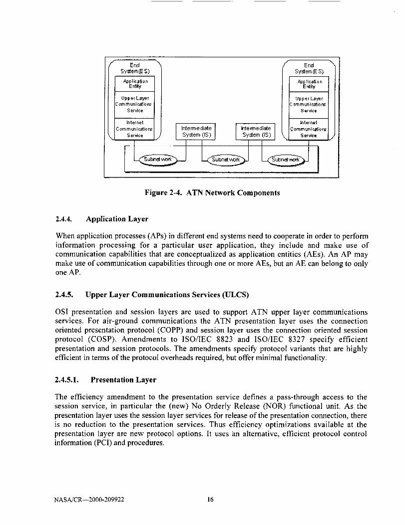
Figure 2-4 shows the constituent elements of both ATN end system and intermediate system
according to the OSI 7-layer reference model, and presents the end-to-end relationship over these
layers.
NASA/CR--2000-209922 15
r End "x
System(E S)
_plicalJon
Ent_
UpperLayerCommunications
Serx,loe
Internet
Com m un ir..aI_iore
S erx,ice
# EndSystem (ES)
Applioa_on
Ent_
Upper Layer2 om m unicatio ns
Service
Inter net
J I Intermediate Intermediate [ Communicatier6System (IS) System (IS) N Ser_oe
Figure 2-4. ATN Network Components
2.4.4. Application Layer
When application processes (APs) in different end systems need to cooperate in order to perform
information processing for a particular user application, they include and make use of
communication capabilities that are conceptualized as application entities (AEs). An AP may
make use of communication capabilities through one or more AEs, but an AE can belong to onlyone AP.
2.4.5. Upper Layer Communications Services (ULCS)
OSI presentation and session layers are used to support ATN upper layer communications
services. For air-ground communications the ATN presentation layer uses the connection
oriented presentation protocol (COPP) and session layer uses the connection oriented session
protocol (COSP). Amendments to ISO/IEC 8823 and ISO/IEC 8327 specify efficient
presentation and session protocols. The amendments specify protocol variants that are highly
efficient in terms of the protocol overheads required, but offer minimal functionality.
2.4.5.1. Presentation Layer
The efficiency amendment to the presentation service defines a pass-through access to the
session service, in particular the (new) No Orderly Release (NOR) functional unit. As the
presentation layer uses the session layer services for release of the presentation connection, there
is no reduction to the presentation services. Thus efficiency optimizations available at the
presentation layer are new protocol options. It uses an alternative, efficient protocol control
information (PCI) and procedures.
NASA/CR--2000-209922 16

The efficiency amendments to the presentation protocol defines a number of protocol options at
the presentation layer that greatly reduce the quantity of presentation PCI in cases where the
presentation user's requirements for presentation functionality are limited. These are:
• Null-encoding
• Short-connect
• Short-encoding
• Nominated context
• Packed encoding
The first two of these options are selected for the initial version of ATN profile, and are
summarized briefly below. The null-encoding protocol option provides an alternative
presentation protocol for data transfer with zero PCI which can be negotiated at connection
establishment only if one of the following conditions is true:
The presentation context definition list contains precisely one item in which the abstract
syntax name is known to the responding presentation protocol machine by bilateral
agreement.
• The presentation context definition list is empty and the default context is known by
bilateral agreement.
The presentation context definition list is empty and the abstract syntax of the default
context is known to the responding presentation protocol machine by bilateral agreement
and is specified in ASN. 1.
The short-connect protocol option permits the null-encoding protocol option, when the
conditions below are true:
• The calling and called presentation selectors are null.
• The presentation-requirements parameter in the P-CONNECT service includes the kernel
functional unit only.
Short PPDU Use and Encoding: The efficiency enhancements to the presentation protocol
include the definition of "short" presentation protocol data units (PPDUs) which are
distinguishable from the conventional longer form PPDUs. The PCI of the short PPDUs is a
single encoded octet.
2.4.5.2. Session Layer Functionality
The full OSI session protocol offers a rich selection of functional units with corresponding
protocol mechanisms to support them. For basic communication applications, most of the
NASA/CR--2000-209922 17
functionality is not required and the protocol overheads may still be excessive for bandwidth-
limited communication paths.
The efficiency amendment to the session service standard specifies the no orderly release (NOR)
functional unit, whose selection by the session user indicates that the user has no requirements
for orderly release of the session connection. Thus, either the application protocol has chosen to
perform this function, or the application association (which is one-to-one with the underlying
session connection) is released by disconnecting the transport connection or by an abortive
release of the session connection. The selection of this functional unit by the initiating session
user permits the initiating session protocol machine to offer the use of the null-encoding protocol
option on an established session connection. The responding session protocol machine can
accept this option if the responding session user has selected only (and nothing other than) the
kernel, full-duplex and no orderly release functional units for use on the connection.
ATN upper layers use the Short Connect and Null Encoding protocol mechanisms to achieve a
session protocol with minimal overheads. In order to accomplish this, the only Session functional
units selected for ATN are Kernel and No Orderly Release (NOR).
NOR is a "negative" function, which removes the ability to perform the orderly release of a
session connection from the Session kernel. This means that data may be lost during the release
of a connection without either user being informed. To overcome this, an orderly release function
is provided by the control function defined in the ATN ULCS SARPs.
The efficiency amendment to the session protocol standard defines a number of protocol options,
namely: null-encoding, short-connect, and short-encoding. The first two of these are selected for
the initial version of an ATN profile, and are summarized briefly as follows:
Null-encoding protocol option of the session protocol, negotiated during connection
setup, that permits a data transfer phase with zero session protocol control information
(PCI) and without the ability to signal the orderly release of the session connection.
Short-connect protocol option. The negotiation of the null encoding protocol option can
be done using the protocol options field of the conventional session establishment
SPDUs. However, there is also the possibility of using the short-connect protocol option
for the establishment SPDUs, which define a one byte PCI for these SPDUs which are
distinct from the leading octet of the current SPDUs. This provides a byte-efficient
negotiation of the null-encoding protocol option provided that there is no need to
exchange session layer addressing information (i.e., the session selectors are null).
It is expected that the short-connect protocol option will be used in conjunction with the
transport connection set-up to achieve interworking with current implementations. For the case
in which the responder also implements this protocol option, an improvement in round-trip
efficiency is obtained by setting up the upper layer connections concurrently with the transportconnection.
NASA/CR--2000-209922 18
2.4.6. Names and Addresses
The ATN naming and addressing scheme is based on the open systems interconnection (OSI)
Reference Model (ISO 7498-3) which supports the principles of unique and unambiguous
identification of information objects and global address standardization. The OSI Basic
Reference Model, Part 3 (ISO 7498-3) distinguishes the concepts of name and address. In brief, a
name is an identifier which is expressed in some language and is used to identify an object (e.g.,
a system, a protocol entity, or an application) while an address is used to locate an object. A
name stays with an object as long as it exists, while the address of the object may change during
its lifetime.
Names must be assigned to any information object that may need to be referred to during
information processing. Addresses must be assigned to any information object to which data may
be directed from another entity.
Names typically have meaning and are thus generally expressed in a mnemonic format.
Correspondingly, the significance of addresses typically increases when descending in the
communications stack. Addresses are generally expressed in a coded or numeric format.
The general philosophy behind the assignment of ATN network addresses is that the
administration of the higher order address parts (i.e., the address domains which are close to the
root of the hierarchical address structure) be performed by entities with a global scope (e.g.,
international organizations such as ISO, ICAO, and IATA). The further down in the hierarchical
address structure one moves (i.e., the closer to the tail of the address), the responsibility for
address assignment and administration is delegated to entities with a more restricted scope (i.e.,
regional, national, or local authorities).
Figure 2-5 illustrates this distributed responsibility for address allocation using the example of an
ATN transport service access point (TSAP) address. This type of address is composed of 10
consecutive address fields comprising a total length of 21 or 22 bytes (depending on the length of
the TSEL field that may be either one or two octets).
According to the ATN addressing plan, address values within the first two fields (AFI and IDI)
are assigned by ISO. ICAO and IATA or ICAO assigns the next three fields (VER, ADM and
RDF) exclusively. The fields six to nine (ARS, LOC, SYS, NSEL) are assigned by ICAO
Regional authorities, State authorities, and aeronautical organizations.
Administration and address value assignment for the last field (TSEL) of an ATN TSAP address
is done locally. It should be noted that, due to this hierarchical structure, several registration
authorities exist for an ATN address. Each registration authority is responsible for the allocation
and registration of values (address fields) within its address space. The address registration
function for the higher order fields of ATN address have already been partially performed in
parallel with the development of the ATN SARPs. As a result, the values of the address prefix up
to and including the RDF field (bytes 1 through 8) of the ATN addresses for ATSC systems are
registered with ISO and ICAO.
NASA/CR--2000-209922 19

ARS(ICAO24-bitA/CAddress)
ISO
I LOC !
11 13
r,-i,-r-l_RDP
ir-lq
sYS
ICAORegion.,State_eronauticalIndusteyAuthorities
Short TSAP
Long TSAP
I"sE'ltSELi19 20 21 22
Locally]
h,,=Ira"-
hY
ATN TSAP Address/Actual TSAPIL
V
ATN NSAP AddressY
Initial DomainPart
Domain Specific Part
Figure 2-5. ATN Transport Service Access Point (TSAP) Address
2.4.7. Name Allocation Principles
Similar to the address allocation, a hierarchical naming structure under the ultimate authority of
ISO has been defined for ATN names. Within this naming hierarchy, names to defined ATN
objects under the ICAO name space that is a sub-space of the ISO name space are allocated by
ICAO. In this context ATN provisions constitute an international register for a set of ATN
names, such as CNS/ATM-1, Application Process Titles and Application Entity Qualifiers. All
ATN objects requiring globally unambiguous names in the context of CNS/ATM-1 are registered
by ICAO therefore further registration of such names by States is not be required.
2.4.8. Responsibilities of Administrations
A number of ATN address fields are expected to be registered and administered at the State level
or by aeronautical industry authorities. Furthermore, ICAO makes provisions for the delegation
of the administrative responsibility for address assignment in certain cases to State authorities or
aeronautical organizations.
States are, therefore, expected to assume full responsibility and administrative duties related to
their own and/or delegated address space(s). In doing so, States should establish the necessary
administrative structure to carry out the administration activities for ATN addresses, i.e. to put in
place an address (and naming) registration authority. The role of an address registration authorityis to:
NASA/CR--2000-209922 20

Assign and make available unambiguous addresses
• Record definitions of the objects to which addresses are assigned
• Disseminate assigned and registered addresses to interested parties within its sphere of
responsibility
A State or organization may choose to delegate its authority for its own address space to another
State or organization. States may even opt to delegate this authority back to ICAO. In the case of
delegation of addressing authority, the respective State(s) or organization(s) has to assume full
administrative duties related to the delegated responsibilities. Appropriate arrangements have to
be established on a mutually agreed basis, which cater for this transfer of authority.
Beside acting as addressing authority for a given portion of ATN addresses, the role of ICAO in
the area of naming and addressing is one of international co-ordination, advice and consultation.
Thus, ICAO may be expected to provide advice to States and organizations to ensure that address
administration is carried out in a manner that supports the orderly and efficient operation of the
global ATN.
Naming, addressing and registration concepts are closely related to directory services. A
directory may be used to store name and address information and can provide lookup functionsto retrieve address or other information on the associated object (e.g., a given application or
service element). Directory information may be stored local to a system if the information is
static and in small amount. However, in a dynamic operating environment like the one for which
ATN is intended, applications cannot always know in advance the current addresses and names
of all other communication partners. Consequently, a simple directory service for use between
aircraft and ground entities, the context management application (CMA), has been specified in
ATN SARPs.
2.4.9. Naming and Addressing Domains
Unambiguity of ATN names and ATN addresses is achieved through the use of naming/
addressing domains with firmly allocated naming/addressing authorities. A naming/addressingdomain is the set of names/addresses that are assignable to objects of a particular type.
Independent naming/addressing domains exist for objects of different types (e.g., an application
process, a network entity or a subnetwork point of attachment). Each one of the
naming/addressing domain is administered by a naming/addressing authority.
The following addressing elements exist for ATN internetwork:
An ATN Network Entity Title (NET) is a 20-octet string used to uniquely identify and
locate a network layer entity of an ATN system (router or end system), and thus, in
networking terms, is used to identify the system itself. Due to the global nature of the
ATN internetwork addressing plan, a system's NET can be used to locate it anywhere
within the ATN. The syntax of an ATN NET is equivalent to that of an ATN NSAP
NASA/CR--2000-209922 21

address. It differs from the NSAP addresses assigned to the same system only in the last
octet (i.e., the network selector (NSEL) field value).
An ATN NSAP Address is a 20-octet string used to uniquely identify and locate a given
NSAP (i.e., a network service user) within the context of ATN.
Each ATN Administrative Domain Identifier identifies an unique domain address
comprised of the AFI, IDI, VER and ADM fields of an ATN NSAP address. An
administrative domain identifier is the prefix of all ATN NSAP addresses and NETs
within the same ATN administrative domain.
Each ATN routing domain can be identified by an unique, unvarying 11-octet ATN
routing domain identifier comprising of the AFI, IDI, VER, ADM, RDF and ARS fields
of an ATN NSAP address. A routing domain identifier is the prefix of all ATN NSAP
addresses and NETs within the same ATN routing domain.
2.4.10. Upper Layer and Application Elements
The following addressing elements exist for ATN upper layer and application elements:
An ATN transport address, or an ATN TSAP address, uniquely identifies and locates a
given transport service user within the context of the ATN. An ATN TSAP address is
comprised of a one- or two-octet TSAP selector (TSEL) appended to the ATN system's
NSAP address. Consequently, the TSEL identifies and locates a given transport service
user within the context of the ATN system's NSAP address which, in turn identifies a
particular network service user. Consequently, TSEL values have only a local scope (i.e.,
within a given ATN End System), and do not need global registration.
An ATN session address, or an ATN SSAP address, uniquely identifies and locates a
given session service user within the context of ATN. A SSAP address is comprised of a
SSAP selector (SSEL) appended to the TSAP address. Consequently, the SSEL identifies
and locates a given session service user within the context of ATN system's TSAP
address. SSEL values have only a scope local to a given ATN system and do not need
global registration.
An ATN application address, or an ATN PSAP address, uniquely identifies and locates a
given application within the context of the ATN. A PSAP address is comprised of a
PSAP selector (PSEL) appended to the ATN system's SSAP address. Consequently, the
PSEL identifies and locates a given session service user within the context of the ATN
system's SSAP address. For initial implementations, the application address of an ATN
application is a PSAP address with absent session and presentation selectors (SSEL and
PSEL). Thus it has the form of a TSAP address.
• An ATN application name, or an ATN application entity title (AE-title), uniquely
identifies a given application within the context of the ATN. An AE-title consists of an
NASA/CR--2000-209922 22

applicationprocesstitle (AP-title) and an AE-qualifier. The AP-title is the name of the
application process that contains the ATN application. The AE-qualifier uniquely
identifies this ATN application within the context of the application process. For initial
implementation, the AP-title of an ATN application that is hosted by a ground system
includes the ICAO Facility Designator, whereas the AP-title of an ATN application that
is hosted by an aircraft system includes the ICAO 24-bit aircraft address.
AP-Titles and AE-Qualifiers may be assigned either as an attribute-based name form or
an object identifier name form. When an AP-Title is allocated as an attribute-based name
form, all of the associated AE-Qualifiers must also be assigned an attribute-based name
form. Correspondingly, when an AP-Title is allocated as an object identifier name form,
all of the associated AE-Qualifiers must also be assigned an object identifier name form.
The application name may be used as input to a directory service to determine the address
(i.e., the PSAP address) of a given application.
It may at times be necessary to distinguish between the various invocations of a given AE
running concurrently as part of a given application process (AP). This is done through the
use of AE Invocation Identifiers that must be unambiguous only within the scope of the
{AP-invocation, AE} pair, and thus do not have to be registered. The use of invocation
identifiers is not required for initial ATN implementation.
Application processes are each named in terms of a unique application process title (AP-
title) which unambiguously identifies the application process throughout the OSI
environment. Application processes are those elements in a given ATN end system that
perform the information processing for particular user applications. It may at times be
necessary to make a distinction between the various invocations of a given AP running
concurrently on an end system. This is done through the use of AP Invocation Identifiers
that must be unambiguous only within the scope of the AP, and thus do not have to be
registered. The use of invocation identifiers is not required for initial ATN
implementation.
2.4.11. Internet Communication Services OCS)
The internet communications services consists of the services provided by the transport and
network layers of the ATN protocol architecture. ATN is a data communications internetworkarchitecture that:
Provides a common communications service for all air traffic services communications
(ATSC) and aeronautical industry service communication (AINSC) applications that
require either ground/ground or air-ground data communications services.
• Integrates and uses existing communications networks and infrastructure wherever
possible.
NASA/CR--2000-209922 23

Provides a communications service which meets the security and safety requirements of
ATSC and AINSC applications, including the reliable and timely delivery of user data toits intended destination.
Accommodates the different grades of service required by each ATSC and A1NSC
application, and the organizational policies for interconnection and routing specified by
each participating organization.
While these capabilities might, at first sight, appear ambitious, the reality is that for the ATN
users, the internetwork will be straightforward and simple to use. This is because ATN
architecture deliberately places the responsibility for routing and maintaining an internetwork's
operational status on the "routers" and therefore enables the End System to have only a minimal
networking capability.
2.4.12. ATN Transport Layer
ATN transport layer service provides transparent transfer of data between transport service users.
All protocols defined in the transport layer have an 'End-to-End' significance, where the 'Ends'
are defined as co-operating transport entities on two ATN host computers. The transport protocol
operates only between end systems. Within ATN, transport layer entities communicate over the
ATN using the network service provided by ATN network layer entities.
There are two modes of the transport service - Connectionless mode Transport Service and
Connection-mode Transport Service. The connectionless mode service allows two transport
users to exchange individual datagrams, without flow control or the need to have previously
established a connection, but with no guarantee of delivery. The connection-mode service allows
two transport service users to negotiate a communications channel with a set of common
characteristics, including reliable delivery of data units and guaranteed (very high probability)
order of delivery.
The two OSI protocols that provide the two modes of the transport service have separate
specifications, and operate independently. Based on the higher level protocols operating within a
given ATN host computer, one or both of the transport protocols may be implemented. Neither
transport protocol is concerned with routing and relaying of data between End Systems, which is
the responsibility of the network layer. The protocol in support of the CLTS is specified in
ISO/IEC 8602, and the protocol in support of the COTS is specified to be ISO/IEC 8073 Class 4.
2.4.13. ATN Network Layer
The OSI network layer service, like the OSI transport service is specified to provide both a
connection mode and a connectionless mode service. However, in ATN the network layer
service is restricted to the connectionless mode only. This is because, unlike the transport layer,
the same network protocols must be implemented in every system in the internetwork if
interoperability is to be guaranteed. In the case of the transport layer, the mode of the service
required depends on the requirements of the users. The End Systems that implement the same
NASA/CR--2000-209922 24

applicationsmustalsoimplementthesametransportlayerprotocols.However,the internetworkitself must relay the dataof all users,regardlessof the modeof the transportserviceused.Inorderto provideuniversalconnectivity,aconsistentsetof protocolsmustbe implementedacrossthe internetwork.Even if universalconnectivitywas ruledout, in practice,mostISswould stillhaveto supportall modesimplementedby ESs becauseof the tendencyfor datapathwaystocrosseachotherregardlessof thenetworkservicemodesupportedby eachsuchdatapathway.
It is thuscosteffective to supportonly onemodeof the networkservice.Implementationcostsarereduced,andthecomplexityof validation is alsoreduced.Furthermore,mobile routing is notyet believedto be practicablewhenusing the connectionmodenetwork service.The network
layer service is independent of the transport layer service and may be used by ISO/IEC 8602 to
provide the CLTS and by ISOflEC 8073 (class 4 procedures only) to provide the COTS.
The OSI network layer comprises three sub-layers or roles:
• Subnetwork Independent Convergence Role, which is responsible for providing a
consistent network layer service regardless of the underlying subnetwork.
Subnetwork Dependent Convergence Role,
subnetwork independent convergence role
subnetworks.
which decouples the functions of thefrom the characteristics of different
• Subnetwork Access Role, which contains those aspects of the network layer specific to
each subnetwork.
2.4.14. SubnetworkIndependent Role
In an ES, the subnetwork independent role is responsible for providing the OSI network service
independent of the real subnetwork(s) to which the ES is attached. In an IS, the subnetwork
independent role is responsible for the routing and relaying of user data along its route between
the two communicating users. The protocols that support the exchange of routing information are
also contained within this functional area.
In support of the connectionless mode network service, it is a mandatory requirement that all
ATN ESs and ISs implement the ISO/IEC 8473 internetworking protocol. This is a subnetwork
independent protocol and supports the relaying of connectionless data protocol data units (PDUs)
over multiple subnetworks. By choosing such a protocol as its unifying characteristic, the ATN is
cast as a subnetwork independent internetwork. CLNP supports the ISO global network
addressing plan, quality of service spec]fication, congestion control, and segmentation and
reassembly of data packets. Additionally, provisions exist within CLNP for diagnostic actions
such as end-to-end route recording and error reporting.
NASA/CR--2000-209922 25

2.4.15. ISO/IEC 8473 Connectionless Network Protocol (CLNP)
CLNP is a simple protocol supporting the transfer of "datagrams" - packets of data transferred
from sender to receiver without the need to establish a connection in advance. Data transferred
using CLNP is formatted as a block of data preceded by a protocol header containing the
addresses of the sender and destination, the priority of the' data, any security label associated with
it, and quality of service requirements. Header and data must together not exceed 64 kilobytes.
An ATN user may, at any time send a CLNP formatted datagram to any valid destination
address. The user does this by passing the datagram over the access subnetwork to the ATN
router. The ATN router will inspect the protocol header, and it is then the ATN router's
responsibility to forward the datagram through the ATN to the ATN router which provides ATN
access to the addressed destination. How it does this is internal to the ATN and hence hidden
from the user, although the forwarding process must respect the data priority and the quality of
service and security requirements identified in the protocol header. Once the datagram has
arrived at the ATN router which provides ATN access to the addressed destination, it is then
transferred over the destination's access subnetwork to the destination user. If the destination
user is offiine (e.g., switched off), the datagram is discarded and an error report is optionallyreturned to the sender.
2.4.16. Connectionless Network Protocol Header Format
Figure 2-6 shows the header format used by the connectionless network protocol used by the
ATN protocol at the network layer.
Network Layer Protocol Identifier Length Indicator
Version Protocol Id Extension Lifetime
SP I MS I E/R I Type
Checksum
Segment Length
Destination Address Length Indictor
Destination Address
Source Address Length Indictor
Data Unit Identifier
Source Address
Segment Offset [
Options
Total Length
Data
Figure 2-6. CLNP Header
NASA/CR--2000-209922 26

The network layer protocol identifier is set to binary 1000 0001 to identify CLNP network layer
protocol. The value of this field is set to binary 0000 0000 to identify the inactive Network layer
protocol subset. Length indicator field indicates the length in octets of the header. A binary
number, with a maximum value of 254 (1111 1110) indicates this length. The value 255 (l 111
1111) is reserved for possible future extensions.
The version/protocol identifier extension field is set to binary 0000 0001, which identifies the
standard version 1 of this protocol. The PDU lifetime field is encoded as a binary number
representing the remaining lifetime of the PDU, in units of 500 ms.
The flag field consists of segmentation permitted (SP), more segments (MS), error report (ER),
type code and segment length. The segment length field specifies the entire length of the PDU in
octets, including both header and data (if present). When the full protocol is employed and a
PDU is not segmented, the value of this field is identical to the value of the total length field
located in the segmentation part of the header. When the non-segmenting protocol subset is
employed, no segmentation part is present in the header. In this case, the segment length field
specifies the entire length of the initial PDU, including both header and data (if present). The
value of the segment length field shall not be changed for the lifetime of the PDU.
The checksum is computed on the entire PDU header. For the Data, Echo Request, and Echo
Reply PDUs, this includes the segmentation and options parts (if present). For the Error Report
PDU, this includes the reason for discard field as well. A checksum value of zero (0) is reserved
to indicate that the checksum is to be ignored. The operation of the PDU header error detection
function ensures that the value zero does not represent a valid checksum. A non-zero value
indicates that the checksum shall be processed. If the checksum calculation fails, the PDU shall
be discarded.
The destination and source addresses used by this protocol are network service access point
addresses or network entity titles as defined in CCITT Rec. X.2131ISOflEC 8348. The
destination and source addresses are of variable length. The destination and source addresses are
encoded as network protocol address information in the destination address and source address
fields using the preferred encoding defined in CCITT Rec. X.213 [ISO/IEC 8348. The destination
address length indicator field specifies the length of the destination address, in octets, Thedestination address field follows the destination address length indicator field. The source
address length indicator field specifies the length of the source address, in octets, and follows thedestination address field. The source address field follows the source address length indicator
field.
The data unit identifier identifies an Initial PDU (and hence, its derived PDUs) so that a
segmented data unit may be correctly reassembled. The data unit identifier size is two octets.
For each derived PDU, the segment offset field specifies the relative position of the segment
contained in the data part of the derived PDU with respect to the start of the data part of theinitial PDU. The offset is measured in units of octets. The offset of the first segment (and hence,
NASA/CR--2000- 209922 27

the initial PDU) is zero; an unsegmented (initial) PDU has a segment offset value of zero. The
value of this field shall be multiples of eight.
The total length field specifies the entire length of the initial PDU in octets, including both the
header and data. The value of this field shall not be changed for the lifetime of an initial PDU
(and hence, it's derived PDUs).
If the options part is present, it may contain one or more parameters. The number of parameters
that may be contained in the options part is constrained by the length of the options part and by
the length of the individual optional parameters. The available options are padding, security,
source routing, recording of route, quality of service maintenance, priority, and data part. The
data part may contain any number of octets up to one less than the maximum number that can be
placed in the SN-Userdata parameter of the underlying SN-UNITDATA primitive. Therefore,
the inactive Network layer protocol can be used only when the length of the NS-Userdata
parameter in the N-UNITDATA primitive is constrained to be less than or equal to the value of
the length of the SN-Userdata parameter minus one.
2.4.17. ATN Addressing
The ATN addressing plan is based on ISO/IEC 8348. The structure of the ATN network address
is shown in Figure 2-7.
Initial Domain Part (lOP) j Domain Specific Part (DSP) J
hIJthorty Format Initial Domain [ Vl_r_ion ._lrnin_ration Routing A:lmin_rat_'e Locati_ System N SAPIdentifier Identifier [ Domain Regior_l Identifier Selector
Fixed"_lue : 00271 I I F°_' Selec_°rI l [Fixed V'alue = 47 .........................................................................................................
Figure 2-7. ATN Address Structure
Table 2-3 presents the various address fields and their size in octets and bits. ISO/_C 8348 has
specified how the Global Network Addressing Domain is broken down into a number of
subordinate Network Addressing Domains, each of which is identified by an unique identifier
that forms the initial part of all NSAP Addresses and NETs in those sub-ordinate domains. The
parts are know as:
• Initial Domain Part (IDP)
• Domain Specific Part (DSP)
NASA/CR--2000-209922 28

The IDP itself is defined as comprising of two parts: an Authority Format Identifier (AFI) and an
Initial Domain Identifier (IDI). The AFI identifies the format and allocation procedures for the
IDI and the format of the remainder of the NSAP Address. ATN NSAP Address Format shown
in Figure 2-7 starts with the AFI and IDI fields required by ISOfIEC 8348. It ends with the
System ID (SYS) and SEL fields required by ISO_EC 10589. The remaining DSP fields are
specified and used to co-ordinate the allocation of ATN NSAP Addresses. In ISO/IEC 8348
terms, the IDP has an abstract decimal syntax, and the DSP has an abstract binary syntax. The
reason for the use of the word abstract is to emphasize the fact that the actual encoding is outside
of the scope of ISO/IEC 8348, and instead is the responsibility of the standards that specify the
encoding of network layer protocols.
Table 2-3. ATN Address Fields Sizes
Field Name Size (octets)
1 AFI 1
2 IDI 3
3 VER I
4 ADM 3
5 RDF I
6 ARS 3
7 LOC 2
8 SYS 6
9 SEL 1
TOTAL 21 octets
Size (bits)
8
24
8
24
8
24
16
48
8
168 bits
ISO/IEC 8348 does, however, describe two possible encoding schemes, the "preferred binary
encoding" and the "preferred decimal encoding." ISOflEC 8473 mandates the use of the
preferred binary encoding for CLNP, while ISOflEC 10747 mandates a modified version of the
preferred binary encoding in order to cope with bit aligned NSAP Address Prefixes. In
consequence, it only specifies how each field of the DSP is allocated as an unsigned binary
number. The actual encoding of the resulting bit string in an NPDU is then according to the
applicable protocol specification.
In the Initial Domain Part (IDP) the Authority Format Identifier (AFI) always set to 47 decimal
and the Initial Domain Identifier (IDI) always set to 0027 decimal.
In the Domain Specific Part (DSP) the purpose of the VER field is to partition ATN network
addressing domain into a number of sub-ordinate addressing domains. The assigned values and
meanings are shown in Table 2-4.
NASA/CR--2000-209922 29

Table 2-4. Version (VER) Field Values
Network Addressing Domain VER Field Value
Fixed AINSC 0000 0001
Mobile AINSC 0100 0001
Fixed ATSC 1000 0001
Mobile ATSC 1100 0001
AINSC = Aeronautical Industry Service Communications
ATSC = Air Traffic Services Communications
The purpose of the Administration (ADM) field is to sub-divide the network addressing domains
introduced by the VER field into a further set of subordinate network addressing domains, and to
permit involved administration (i.e., address allocation) of each resulting domain to an individual
state organization. Table 2-5 shows the ICAO regional identifier used for the ADM field.
Table 2-5. ICAO Regional Identifiers
ADM FieldICAO Region
(first octet)
[1000 0000] Africa
[1000 0001] Asia
[1000 0010] Caribbean
[1000 0011] Europe
[1000 0100] Middle East
[1000 0101] North America
[1000 0110] North Atlantic
[1000 0111] Pacific
[1000 1000] South America
The Routing Domain Format (RDF) field has no value and it is left in the address structure
purely for historical and compatibility with ISO compliant addressing plans. In fixed network
addressing the Administrative Regional Selector (ARS) field is used to distinguish routing
domains operated by the same state or organization. In mobile network addressing this field is
used to identify the aircraft on which the addressed system is located.
In fixed network addressing the Location (LOC) field is used to distinguish Routing Areas within
the same routing domain and in mobile network addressing the LOC field is used to distinguish
routing areas within the same mobile routing domain. The System Identifier (SYS) field is used
NASA/CR--2000-209922 30

to uniquely identify the End-System or Intermediate-System within a routing domain. The NSAP
Selector (SEL) field is used to identify the End-System or Intermediate-System network entity
service user process responsible for originating or receiving network service data units (NSDUs).
2.4.18. ATN Routing Protocols
There are three basic routing protocols associated with the ATN: Two intra-domain routing
protocols and one inter-domain routing protocol. The intra-domain routing protocols are End
System-to Intermediate System (ES-to-IS) and Intermediate System-to-Intermediate System (IS-
to-IS). Both of these protocols are specified by ISO specification 9542 and 10589 respectively.
The primary inter-domain routing protocol for the ATN is Inter-Domain Routing Protocol
(IDRP) specified by ISO specification 10747.
2.4.19. ATN Routing
Unlike ACARS the ATN is based on a distributed routing. The routing architecture based on ISO
standard protocols is shown in Figure 2-8. The International Organization for Standardization
(ISO) developed a complete suite of routing protocols for use in the Open Systems
Interconnection (OSI) protocol suite. These include:
• Intermediate System-to-Intermediate Systems (IS-IS)
• End System-to-Intermediate System (ES-IS)
• Inter-Domain Routing Protocol (IDRP).
Figure 2-8. Simplified View of ATN Routing
NASA/CR--2000-209922 31

2.4.19.1. End System-to-Intermediate System (ES-IS)
The ISO/IEC 9542 ES-IS protocol provides a mechanism for ESs and ISs to exchange
connectivity information within a local subnetwork environment. It is recommended for
implementation in all ATN ESs and all ATN ISs that support ES attachment. This protocol
enables ESs and ISs to dynamically discover each other when attached to the same subnetwork
(only on broadcast subnetworks), and for ISs to inform ESs of optimal routes. In the absence of
ISs (on broadcast subnetworks), ESs may also locate each other on an as needed basis. The ES-
IS protocol also complements the IS-IS routing protocols to support dynamic discovery of other
ISs and/or their NETs. It is also used in a similar manner to support the Inter-Domain RoutingProtocol over mobile subnetworks.
2.4.19.2. Intermediate System-to-Intermediate System (IS-IS)
Intermediate System-to-Intermediate System (IS-IS) is an OSI link-state hierarchical routing
protocol that floods the network with link-state information to build a complete, consistent
picture of network topology. The ISO/IEC 10589 IS-IS intra-domain routing information
exchange protocol is used by ISs within the same routing domain to exchange connectivity
information. This protocol works at two levels. Level 1 operates within the same routing area,
while level 2 operates between routing areas. From the information exchanged by this protocol,
ISs build a topology map of the local routing area at level 1, or routing area connectivity, at level
2. From this map, optimal routes can be found and the relevant information provided to each IS's
Forwarding Information Base.
2.4.19.3. Inter-Domain Routing Protocol (IDRP)
The Inter-Domain Routing Protocol is an OSI protocol that specifies how routers communicate
with routers in different domains. IDRP is designed to operate seamlessly with CLNP, ES-IS,
and IS-IS. IDRP is based on the Border Gateway Protocol (BGP), an Inter-Domain Routing
Protocol that originated in the IP community. IDRP features include the following:
• Support for CLNP quality of service (QoS)
• Loop suppression by keeping track of all RDs traversed by a route
• Reduction of route information and processing by using confederations, the compression
of RD path information, and other means
• Reliability by using a built-in reliable transport
• Security by using cryptographic signatures on a per-packet basis
• Route servers
NASA/CR--2000- 209922 32

IDRP introduces several environment-specific terms. A Border Intermediate System (BIS) is an
IS that participates in interdomain routing and, as such, uses IDRP. Routing Domain (RD) is a
group of ESs and ISs that operate under the same set of administrative rules and share a common
routing plan. A Routing-Domain Identifier (RDI) is an unique RD identifier.
Routing-Information Base (RIB) is a routing database used by IDRP that is built by each BISfrom information received from within the RD and from other BISs. A RIB contains the set of
routes chosen for use by a particular BIS. A Confederation is a group of RDs that appears to RDs
outside the confederation as a single RD. The confederation's topology is not visible to RDs
outside the confederation. Confederations must be nested within one another and help reduce
network traffic by acting as internetwork firewalls.
ATN has adopted the ISO/IEC 10747 Inter-Domain Routing Protocol for the exchange of
dynamic routing information at the inter-domain level. IDRP is a "vector distant" routing
protocol and is concerned with the distribution of routes. A route comprises a set of address
prefixes for all destinations along the route and the router's path (i.e., the list of routing domains
through which the route passes in order to reach those destinations). In addition, a route may be
further characterized by various service quality metrics (e.g., transit delay).
Under IDRP, specialized Boundary Routers in each routing domain advertise to Boundary
Routers in adjacent routing domains routes to the systems contained in that routing domain.
Typically, there is a route for each performance metric and security category supported. Thedestination of these routes is the address prefix(es) that characterizes the routing domain. The
receiving routing domains then store this information and use it when they need to route packets
to destinations within the other routing domain. A route so received may also be re-advertised to
other routing domains adjacent to the routing domain that first received it, and onwards
throughout the ATN Internet. Ultimately, every routing domain in the ATN Internet can receive
a route to every other routing domain. However, without any other functionality, IDRP would
not provide a scaleable approach to routing. In order to provide such a scaleable architecture,
IDRP enables the aggregation of routes to routing domains with common address prefixes, into a
single route. It is thereby possible for the number of routes known to any one router to be kept
within realistic limits without reducing connectivity within the Internetwork.
2.4.20. Use of Policy Based Routing by Organizations
It is the BIS's responsibility to determine which routes, if any, it will advertise to another BIS,
and the use it will make of routes that it receives. When the BISs within a routing domain receive
alternative routes to the same destination, they must collectively determine which is the best
route and hence which of the alternatives will be used. The set of rules which determines the
advertisement and use of routes is known as a Routing Policy, and each organizational user of
the ATN must determine and apply their own routing policy.
It is the need for policy based routing between different organizations that underlies the need for
the existence of routing domain. Policy based routing enable users to control external access to
their communications resources, and to protect themselves from problems elsewhere in the
NASA/CR--2000-209922 33
internetwork.BISs may also,dependingon routing policy, advertiseto BISs in other routingdomain routesthat havebeenreceivedfrom anotherrouting domain,andtherebyoffer transitfacilities. However, routing policy may alsopreventsuch routesfrom being re-advertisedandhencedenytransitfacilities.
OrganizationalATN usersmustthereforeensurethat theyeitherhavedirectconnectionswith theATN routing domainswith which communicationis necessary,or that thoserouting domainswith which direct connectionsexist offer suitabletransit facilities to the remainder.In principle,this could be done on a bilateral basisbetweenATN organizationaluserson an "as needed"basis.This is generally what is expectedfor the supportof ground-groundcommunications.However,for air-groundapplicationssupport,this is unlikely to beanefficient strategyandmayactuallypreventuseful communicationby putting too high a cost onestablishinga usablepathevenwhenconnectivityalreadyexists.
Instead,it is intended that ATN interconnections for support of air-ground communications are
coordinated on both a regional and worldwide basis. Therefore, an ATN backbone (of Routing
Domains offering general transit facilities) is created with either a clear apportionment of costs
or a known tariff for the use of transit facilities. In this way users can gain access to the full
capabilities of ATN quickly and cheaply.
Policy based routing plays a significant role in ATN, where it is used to support user
requirements for control over the user of data links and for optimizing the distribution of routing
information for routes to mobile systems.
2.4.21. Mobile Users
ATN will incorporate many "mobile" subnetworks. Examples of such subnetworks include SSR
Mode S, AMSS and VDL. If an aircraft were to attach to only one mobile subnetwork and never
to any other, then even though sometimes it may be attached and at other times not attached, this
has no consequence for ATN. This is because from the point of view of the rest of ATN, it would
be no different from a fixed system that was occasionally off-line. However, that is not how
mobile subnetworks are used. An aircraft will attach to many different mobile subnetworks
during the course of its flight. A long haul aircraft may move between the coverage areas of
different satellites; an aircraft flying over a land mass will fly between different Mode S
subnetworks as it passes over different countries. At the same time, the applications onboard the
aircraft will need to maintain contact with applications on the ground. Mobile platforms thus
require special routing considerations.
In ATN, mobile platforms are treated in a similar manner as organizational users. That is, the
systems onboard an aircraft are required to form a routing domain and hence must include an
ATN router that is also a BIS. This is partly because the ISO/IEC 10747 routing protocol
provides a relatively efficient mechanism for the transfer of routing information over low
bandwidth links. In addition, aircraft are almost always organizationally separate and talk to the
ground systems with which they are in contact. Therefore, the same requirements for policy
based routing apply.
NASA/CR--2000-209922 34

The existence of mobile users has a significant impact on the organization of the ground based
ATN. While the ground topology will change only slowly, each aircral_'s point of contact with
the ground ATN will change rapidly with a consequent impact on the volume of routing
information exchanged, and the routing tables in each router. A strategy is necessary for
containing this high rate of information flow, and also to avoid the problems of routing
instability caused by a rapid change of routing information.
Therefore, the ATN Mobile Routing Strategy is based on a two level concept of default route
providers. The first level is provided by a default route provider to all aircraft in a given region
(known as an ATN Island). This default route provider is kept informed about routes to all
aircraft currently in that region and hence can always provide a path to such aircraft. Several
such default route providers may exist in the same region and collectively they are said to form
the ATN Island Backbone.
The second level is provided by an aircraft's home. The "home" of an aircraft does not
necessarily relate to an airline's headquarters, its maintenance facilities, or indeed any
geographical concept of "home". It is simply a particular ATN routing domain, and, in principle,
any ATN RD will do. It may be a RD belonging to an aircraft's airline, but equally it may belong
to a Service Provider or an Administration. Typically, all aircraft belonging to the same airline or
the General Aviation (GA) aircraft of a single country share the same home.
ATN's default route providers in each ATN Island keep the "home" informed about the location
of all of its aircraft. Thus, if a particular default route provider needs to route a packet to an
aircraft for which it does not have an explicit route (i.e., it is not in the same region), all it has to
do is to route the packet to the aircraft's known home. From there it can be forwarded to the
ATN Island with which it is in contact and thence to that aircraft.
2.4.21.1. Route Initiation
The establishment of a communications path between BISs in any two routing domains is known
as "Route Initiation." The procedures apply to the establishment of both ground/ground and
air/ground communications. However, as opposed to the ground/ground case, Route Initiation for
mobile users is dynamic and follows ICAO specified procedures.
2.4.21.2. Routing Control
An important user requirement is that users can specify, on a per application basis, routing
control requirements. For AOC applications, the requirement is for control over the air/ground
data link used for air/ground applications. For ATSC applications, the requirement is to follow
only ATSC approved routes, and further, to be able to classify routes in the range class A to class
H, and for the user data to follow a route of the most appropriate class. Some administrations
may also restrict the type of traffic carried over certain air/ground data links. Such restrictions
must also be taken into account. ATN meets these requirements by:
NASA/CR--2000-209922 35

Permitting users to identify in the CLNP header the traffic type of the data being
conveyed (e.g., ATSC, AOC, and General Communications) and the routing control
requirements.
• Carrying information about the air/ground data links a route traverses and any restrictions
placed upon those data links in each IDRP route.
• Carrying information about whether a route is approved for ATSC purposes and the
assigned ATSC Class of the route in each IDRP Route.
When an ATN router forwards a CLNP PDU, the user requirements are matched against the
available routes and the appropriate route is then selected. In the case of AOC traffic, the user' s
requirements are enforced in a "strong" manner. That is, if a route meeting the user's
requirements is not available, then the data is discarded. In the case of ATSC traffic, a similar
"strong" interpretation is made of the requirement to follow an ATSC approved route. However,
the router will then simply choose the route that best matches the ATSC Class. This is a route
with the requested class, a higher class, or if no higher class route available, then the ATSC
approved route with the highest specified class out of those available.
2.4.22. ATN Security
Security is of prime concern in aeronautical environment and ATN supports security by
specifying a number of security functions. ATN security functions are mainly concerned with:
• Protecting CNS/ATM applications from internal and external threats.
• Ensuring that application Quality of Service and Routing Policy Requirements are
maintained, including service availability.
• Ensuring that air-ground subnetworks are used in accordance with ITU requirements.
ATN interact provides mechanisms to support bulleted items 2 and 3 only. These mechanisms
are defined to take place in a common domain of trust. The mechanisms use a Security Label in
the header of each CLNP Data PDU to convey information identifying the "traffic type" of the
data and the application's routing policy and/or strong QoS Requirements. Strong QoS
Requirements may only be expressed by ATSC Applications. They are expressed as an ATC
Class identifier and are encoded as part of the ATN Security Label.
Except when a transport connection is used to convey general communications data, each
transport connection is associated with a single ATN Security Label. The value of this label is
determined by the initiating TS-User when the connection is initiated. A responding TS-user may
refuse to accept a transport connection associated with a given ATN Security, but cannot propose
an alternative. It is also not possible to change an ATN Security Label during the lifetime of a
transport connection.
NASA/CR--2000-209922 36

ATN SecurityLabel is neveractuallyencodedintoa TPDUheader.Instead,everyNSDU passedto theNetwork Layer that contains a TPDU from a transport connection associated with an ATN
Security Label is associated with the same ATN Security Label. This is passed as a parameter to
the N-UNITDATA request, and then encoded into the NPDU header. TPDUs from transport
connections associated with different ATN Security Labels cannot be concatenated into the same
NSDU.
There are currently no mechanisms for protecting the Routing Information Base from an
attacker. However, the use of ISO/IEC 10747 type 2 authentication is under consideration for
definition in future versions of this specification.
The Routing Information necessary to support this Security Label is maintained through
information conveyed in the ISO/IEC 10747 Security Path Attribute about each route. ATN
Routers of classes 4 and above reference this routing information during the NPDU forwarding
process in order to meet the application's requirements expressed through the NPDU's Security
Label and to enforce any applicable ITU resolutions on frequency utilization.
2.4.23. ATN Mobility
Without a central node, as is the case with ACARS, mobility becomes more complex. The ATN
is a collection of distributed routers with no centralized processor that has "ultimate knowledge"
of the location of mobile nodes (aircraft).
Mobility in the ATN is primarily handled by IDRP. IDRP features for mobile routing include:
All mobile nodes (in this case aircraft) are assigned a "home" routing domain. This home
routing domain will always have information about where to reach the aircraft or where
the aircraft is attached to the network.
When an uplink message from a ground end-system is sent to the aircraft, it is generally
sent to the home routing domain that has a specific knowledge of where the aircraft is
attached to the network. A router in the home routing domain will then forward the
message to the aircraft.
For downlink message send from an aircraft to a ground end-system, the aircraft need
only have knowledge of the address of the end-system. The message will take the most
preferred route as determined by the routing protocols.
2.4.24. ATN Quality of Service (QoS)
The ATN QoS Requirements are maintained by various functions within the ATN upper layers
and Internet. Data Integrity is maintained by end-to-end checksums. The transport protocol
maintains a checksum on all messages. However, this may not be sufficient to meet the ADSP
NASA/CR--2000-209922 37
requirement and application end-to-end checks may be required. These could be provided by
security mechanisms required to counter external threats.
Availability is maintained by providing multiple alternative routes through the Internet and re-
routing around failures. It is dependent upon the proper operation of the routing information
exchange.
The transport protocol is primarily responsible for ensuring against mis-delivery and for ensuring
receipt of messages. It also reports non-delivery should a transport connection fail. However, it
can only report the probability that mis-delivery has occurred.
Network Design is primarily responsible for ensuring that the transit delay requirements are met,
by ensuring that the path lengths are appropriate and that sufficient network capacity is available.
In the event of network limits being exceeded either through component failures or unexpectedly
high load, congestion management and data prioritization are implemented both by the Internet
and the Transport Protocol in order to share the available network bandwidth and to give
preference to safety related applications.
Priority is used to signal the relative importance and/or precedence of data. Priority is used to
decide which data to process first, or how to resolve contention for access to shared resources in
line with user requirements both within and between applications.
In ATN priority is signaled separately by the application in the transport layer and network layer,
and in ATN subnetworks. In each case, the semantics and use of priority may differ. In the ATN
Internet, priority has the essential role of ensuring that high priority safety related data is not
delayed by low priority non-safety data, especially when the network is overloaded with low
priority data.
Priority in ATN Application Protocols is used to distinguish the relative importance and urgency
of application messages within the context of that application alone.
Note that the priority of an individual transport connection cannot be changed during the lifetime
of the connection. Therefore, if an application exchanges messages belonging to more than one
message category using the connection mode transport service, then a separate transport
connection needs to be established for each message category.
Transport connection priority is concerned with the relationship among transport connections.
This priority determines the relative importance of a transport connection with respect to the
order in which transport connections are to have their QoS degraded, if necessary, and the order
in which transport connections are to be released in order to recover resources.
The transport user specifies the transport connection priority either explicitly or implicitly when
the transport connection is established. Note that there are no procedures required of the ATN
Connectionless Transport Entity in respect to priority, except for mapping the TSDU priority
NASA/CR--2000-209922 38
supplied by the service user (i.e., an ATN Application), to the corresponding Network Layer
Priority and vice versa.
In the ATN Internet Layer, an NPDU of a higher priority is given preferred access to resources.
During peak network utilization periods, higher priority NPDUs may be expected to be more
likely to reach their destination (i.e., are less likely to be discarded by a congested router). In
addition, they may experience lower transit delay (i.e., be more likely to be selected for
transmission from an outgoing queue) than lower priority packets.
Note that in addition to NPDUs containing user (i.e., transport layer) data, the Intemet layer also
forwards routing information contained in CLNP Data PDUs (e.g., IDRP) as distinct NPDUs
(e.g., ES-IS). These must all be handled at the highest priority if changes to network topology are
to be quickly effected and the optimal service provided to users.
In a connection-mode ATN subnetwork, priority is used to distinguish the relative importance of
different data streams (i.e., the data on a subnetwork connection) with respect to gaining access
to communications resources and to maintaining the requested Quality of Service. However, on
some subnetworks (e.g., public data networks), not all data streams will be carrying ATN
messages. Therefore, subnetwork priority is also used to distinguish ATN and non-ATN data
streams.
2.5. IPv4 Protocol Overview
Today's Internet resulted from the US Defense Advanced Research Projects Agency (DARPA)
effort of the early 1970s which involved research at Stanford to design a new set of computer
communication protocols that would allow multiple packet networks to be interconnected in a
flexible and dynamic way. In defense settings, circumstances often prevented detailed planning
for communication system deployment. A dynamic, packet-oriented, multiple-network design
provided the basis for a highly robust and flexible network to support command and control
applications.
The first phase of this work culminated in a demonstration in July 1977, the success of which led
to a sustained effort to implement robust versions of the basic Internet protocols (called TCP/IP
for the two main protocols: Transmission Control Protocol and Internet Protocol). The roles of
DARPA and the Defense Communications Agency were critical both in supplying sustained
funding for implementing the protocols on various computers and operating systems and for the
persistent and determined application of the new protocols to real needs.
By 1980, sufficient experience had been gained that the design of the protocols could be frozen
and a serious effort mounted to require all computers on the Advanced Research Project Agency
Network (ARPANET) to adopt TCP/IP. This effort culminated in a switch to the new protocols
in January 1983. ARPANET had graduated to production use, but it was still an evolving
experimental testbed under the leadership of DARPA and DCA.
NASA/CR--2000-209922 39

2.5.1. ARPANET to NSFNET to Internet
As DARPA and DCA were preparing to convert the organizations they supported to TCP/IP, the
National Science Foundation started an effort called CSNET (for Computer Science Network) to
interconnect the nation's computer science departments, many of which did not have access to
ARPANET. CSNET adopted TCP/IP, but developed a dial-up "Phone-mail" capability for
electronic mail exchange among computers that were not on ARPANET. CSNET pioneered the
use of TCP/IP over the X.25 protocol standard that emerged from commercial packet switching
efforts. Thus, the beginning of the 1980s marked the expansion of U.S. government agency
interest in networking. By the mid-1980s, the Department of Energy and NASA also had becomeinvolved.
National Science Foundation (NSF)'s interest in high-bandwidth attachment was ignited in 1986
after the start of the Supercomputer Centers program. NSF paved the way to link researchers to
the Centers through its sponsorship of NSFNET, which augmented ARPANET as a major
network backbone and eventually replaced ARPANET when ARPANET was retired in 1990.
Then-Senator Gore's 1986 legislation calling for the interconnection of the Centers using fiber
optic technology ultimately led the administration to respond with the High Performance
Computing and Communications (HPCC) Initiative.
Among the most critical decisions that NSF made was to support the creation of "regional" or
"intermediate-level" networks that would aggregate demand from the nation's universities and
feed it to the NSFNET backbone. The backbone itself was initially implemented using gateways
(systems used to route traffic) developed at the University of Delaware and links operating at the
ARPANET speed of 56 Kbps. Because of rapidly increasing demand, NSF in 1988 selected
MERIT (at the University of Michigan) to lead a cooperative agreement with MCI and IBM to
develop a 1.5M bps backbone. IBM developed new routers and MCI supplied t .5 Mbps circuits,
and NSFNET was reborn with roughly 30 times the bandwidth of its predecessor.
The regional networks quickly became the primary means by which universities and other
research institutions linked to the NSFNET backbone. NSF wisely advised these networks that
their seed funding would have limited duration, and they would have to become self-sustaining.
Although this took longer than originally expected, most of the regional networks (such as
BARNET, SURANET, JVNCNET, CICNET, NYSERNET, NWNET, and so on) now have
either gone into the for-profit mode or have spun off for-profit operations.
Because of continued increases in demand, NSF re-visited the cooperative agreement with MCI,
IBM and MERIT. A non-profit organization, Advanced Networks and Services (ANS), was born
and satisfied the demand for Internet capacity using 45 Mbps circuits. The name "Internet" refers
to the global seamless interconnection of networks made possible by the protocols devised in the
1970s through DARPA-sponsored research - the Internet protocols still in use today. The IPv4
protocol stack is the most widely use set of internetworking protocol in use today. It forms the
basis of the Internet or World Wide Web (WWW).
NASA/CR--2000-209922 40
2.5.2. TCP/IPv4 Transport Layer
There are two popular transport protocols used in conjunction with IPv4. The protocols are
Transport Control Protocol (TCP) and User Datagram Protocol (UDP). Transport Control
Protocol (TCP) is a connection oriented transport layer protocol defined originally as
"Transmission Control Protocol," J. Postel, RFC-793, September 1981. User Datagram Protocol
(UDP) is a connectionless transport layer protocol defined originally as "User Datagram
Protocol," J. Postel, RFC-768, August 1980.
2.5.2.1. Reliable Communication
A stream of data sent on a TCP connection is delivered reliably and in order at the destination.
Transmission is made reliable via the use of sequence numbers and acknowledgments.
Conceptually, each octet of data is assigned a sequence number. The sequence number of the
first octet of data in a segment is transmitted with that segment and is called the segment
sequence number. Segments also carry an acknowledgment number which is the sequence
number of the next expected data octet of transmissions in the reverse direction. When the TCP
transmits a segment containing data, it puts a copy on a retransmission queue and starts a timer;
when the acknowledgment for that data is received, the segment is deleted from the queue. If the
acknowledgment is not received before the timer runs out, the segment is retransmitted.
An acknowledgment by TCP does not guarantee that the data has been delivered to the end user,
but only that the receiving TCP has taken the responsibility to do so. To govern the flow of data
between TCPs, a flow control mechanism is employed. The receiving TCP reports a "window" to
the sending TCP. This window specifies the number of octets, starting with the acknowledgment
number, that the receiving TCP is currently prepared to receive.
2.5.2.2. Connection Establishment and Clearing
To identify the separate data streams that a TCP may handle, the TCP provides a port identifier.
Since port identifiers are selected independently by each TCP they might not be unique. To
provide for unique addresses within each TCP, an Internet address identifying the TCP is
concatenated with a port identifier to create a socket which will be unique throughout all
networks connected together.
A connection is fully specified by the pair of sockets at the ends. A local socket may participate
in many connections to different foreign sockets. A connection can be used to carry data in both
directions; that is, it is "full duplex".
2.5.2.3. Data Communication
The data that flows on a connection may be thought of as a stream of octets. The sending user
indicates in each SEND call whether the data in that call (and any preceding calls) should be
immediately pushed through to the receiving user by the setting of the PUSH flag.
NASA/CR--2000-209922 41
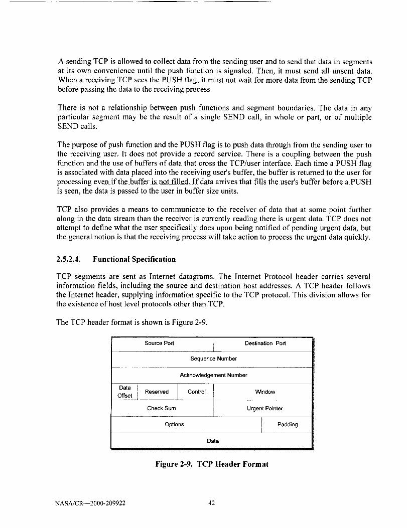
A sending TCP is allowed to collect data from the sending user and to send that data in segments
at its own convenience until the push function is signaled. Then, it must send all unsent data.
When a receiving TCP sees the PUSH flag, it must not wait for more data from the sending TCP
before passing the data to the receiving process.
There is not a relationship between push functions and segment boundaries. The data in any
particular segment may be the result of a single SEND call, in whole or part, or of multipleSEND calls.
The purpose of push function and the PUSH flag is to push data through from the sending user to
the receiving user. It does not provide a record service. There is a coupling between the push
function and the use of buffers of data that cross the TCP/user interface. Each time a PUSH flag
is associated with data placed into the receiving user's buffer, the buffer is returned to the user for
processing even if the buffer is not filled. If data arrives that fills the user's buffer before a PUSH
is seen, the data is passed to the user in buffer size units.
TCP also provides a means to communicate to the receiver of data that at some point further
along in the data stream than the receiver is currently reading there is urgent data. TCP does not
attempt to define what the user specifically does upon being notified of pending urgent dath, but
the general notion is that the receiving process will take action to process the urgent data quickly.
2.5.2.4. Functional Specification
TCP segments are sent as Internet datagrams. The Internet Protocol header carries several
information fields, including the source and destination host addresses. A TCP header follows
the Internet header, supplying information specific to the TCP protocol. This division allows for
the existence of host level protocols other than TCP.
The TCP header format is shown is Figure 2-9.
Source Port _ Destination Port
Sequence Number
Acknowledgement Number
Data I
Offset_._ Reserved Control Window
Check Sum Urgent Pointer
Options Padding
Data
1
Figure 2-9. TCP Header Format
NASA/CR--2000-209922 42

The header consists of a number of fields. These fields are:
• The Source Port field which contains the source port number and is 16 bit wide.
• The Destination Port field holds the destination port number and the size is 16 bits.
The Sequence Number field size is 32 bits. It contains the sequence number of the first
data octet in this segment (except when SYN is present). If SYN is present the sequence
number is the initial sequence number (ISN) and the first data octet is ISN+I.
The Acknowledgment Number field size is 32 bits. If the ACK control bit is set, this field
contains the value of the next sequence number the sender of the segment is expecting to
receive. Once a connection is established, this is always sent.
The Data Offset field size is 4 bits. This field represents the number of 32 bit words in the
TCP header. This indicates where the data begins. The TCP header (even one including
options) is an integral number of 32 bits long.
• The Reserved field is 6 bits long and reserved for future use. This field must be set to a
zero.
• The Control Bits field is 6 bits (from left to right) long and represents the following
values:
w
w
URG
ACK
PSH
RST
SYN
FIN
Urgent Pointer field significant
Acknowledgment field significantPush Function
Reset the connection
Synchronize sequence numbersNo more data from sender
The Window field is 16 bits long. It represents the number of data octets beginning with
the one indicated in the acknowledgment field which the sender of this segment is willing
to accept.
The Checksum field is 16 bits long and is the 16 bit one's complement of the one's
complement sum of all 16 bit words in the header and text. Ifa segment contains an oddnumber of header and text octets to be checksummed, the last octet is padded on the right
with zeros to form a 16 bit word for checksum purposes. The pad is not transmitted as
part of the segment. While computing the checksum, the checksum field itself is replacedwith zeros. The checksum also covers a 96 bit pseudo header conceptually prefixed to the
TCP header. This pseudo header contains the Source Address, the Destination Address,
the Protocol, and TCP length. This gives the TCP protection against misrouted segments.
This information is carried in the Internet Protocol and is transferred across the
NASA/CR--2000-209922 43
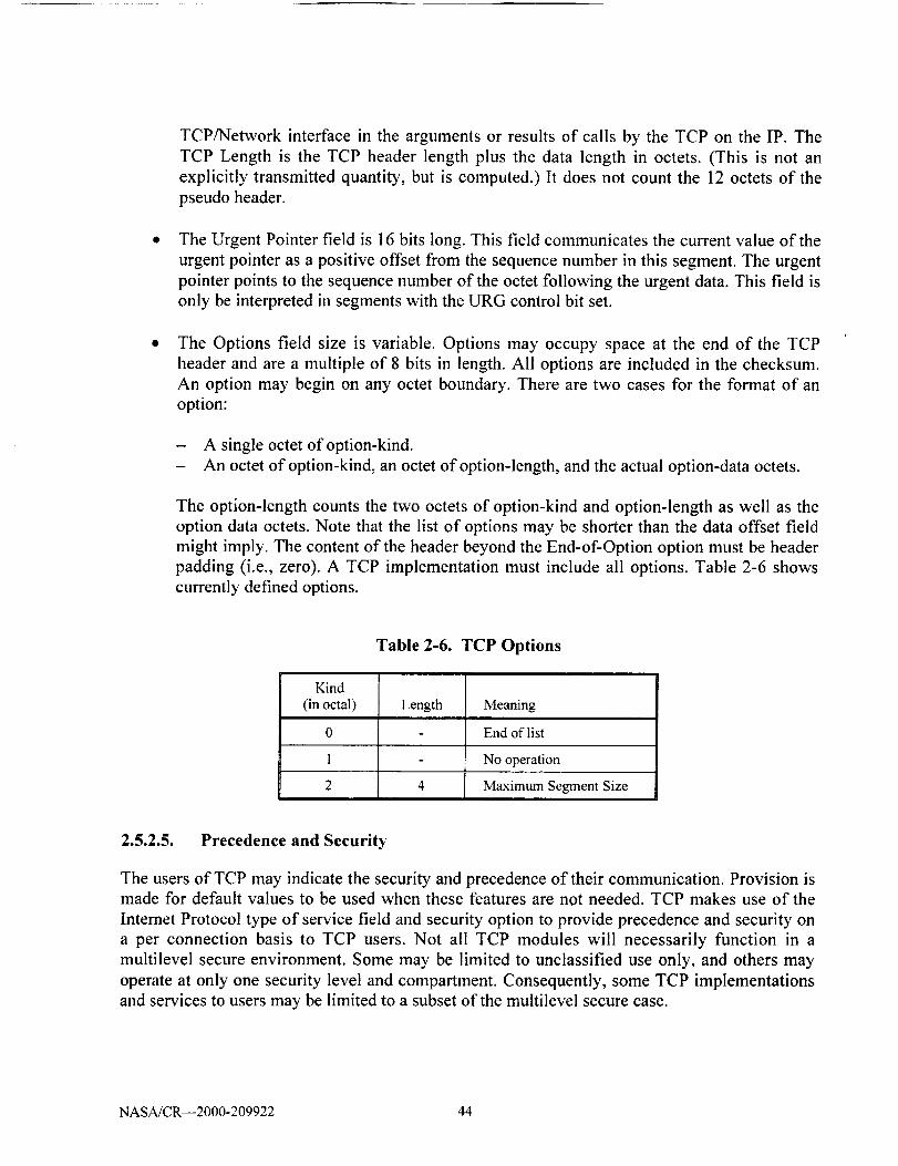
TCP/Network interface in the arguments or results of calls by the TCP on the IP. The
TCP Length is the TCP header length plus the data length in octets. (This is not an
explicitly transmitted quantity, but is computed.) It does not count the 12 octets of the
pseudo header.
The Urgent Pointer field is 16 bits long. This field communicates the current value of the
urgent pointer as a positive offset from the sequence number in this segment. The urgent
pointer points to the sequence number of the octet following the urgent data. This field is
only be interpreted in segments with the URG control bit set.
The Options field size is variable. Options may occupy space at the end of the TCP
header and are a multiple of 8 bits in length. All options are included in the checksum.
An option may begin on any octet boundary. There are two cases for the format of an
option:
- A single octet of option-kind.
- An octet of option-kind, an octet of option-length, and the actual option-data octets.
The option-length counts the two octets of option-kind and option-length as well as the
option data octets. Note that the list of options may be shorter than the data offset field
might imply. The content of the header beyond the End-of-Option option must be header
padding (i.e., zero). A TCP implementation must include all options. Table 2-6 shows
currently defined options.
Table 2-6. TCP Options
Kind
(in octal) Length Meaning
0 End of list
1 No operation
2 4 Maximum Segment Size
2.5.2.5. Precedence and Security
The users of TCP may indicate the security and precedence of their communication. Provision ismade for default values to be used when these features are not needed. TCP makes use of the
Intemet Protocol type of service field and security option to provide precedence and security on
a per connection basis to TCP users. Not all TCP modules will necessarily function in a
multilevel secure environment. Some may be limited to unclassified use only, and others may
operate at only one security level and compartment. Consequently, some TCP implementations
and services to users may be limited to a subset of the multilevel secure case.
NASA/CR--2000-209922 44

TCP modules that operate in a multilevel secure environment must properly mark outgoing
segments with the security, compartment, and precedence. Such TCP modules must also provide
to their users or higher level protocols such as Telnet an interface to allow them to specify the
desired security level, compartment, and precedence of connections. The intent of Precedence
and Security is that connection be allowed only between ports operating with exactly the same
security and compartment values and at the higher of the precedence level requested by the two
ports. The precedence and security parameters used in TCP are exactly those defined in the
Internet Protocol (IP).
A connection attempt with mismatched security/compartment values or a lower precedence value
is rejected by sending a reset. Rejecting a connection due to too low a precedence only occurs
after an acknowledgment of the SYN has been received. Note that TCP modules that operate
only at the default value of precedence will still have to check the precedence of incoming
segments and possibly raise the precedence level they use on the connection. The security
parameters may be used even in a non-secure environment (i.e., the values would indicate
unclassified data), thus hosts in non-secure environments must be prepared to receive the
security parameters, though they need not send them.
2.5.3. IPv4 Network Layer
The TCP/IP protocol architecture supports connectionless network service. IP is a best-effort-
delivery network protocol. The Internet Protocol provides for transmitting blocks of data called a
datagram from sources to destinations, where sources and destinations are hosts identified by
fixed length addresses. The Internet Protocol also provides for fragmentation and reassembly of a
long datagram, if necessary, for transmission through "small packet" networks. The function or
purpose of the Internet Protocol is to move datagrams through an interconnected set of networks.
This is done by passing the datagrams from one internet module to another until the destination
is reached. The internet modules reside in hosts and gateways in the internet system. The
datagrams are routed from one internet module to another through individual networks based on
the interpretation of an internet address. Thus, one important mechanism of the Internet Protocol
is the internet address.
In the routing of messages from one internet module to another, datagrams may need to traverse
a network whose maximum packet size is smaller than the size of the datagram. To overcome
this difficulty, a fragmentation mechanism is provided in the internet protocol.
2.5.4. IPv4 Header Format
The IPv4 packet header format is presented in Figure 2-t 0. The Version field is 4 bits long and
indicates the format of the internet header. The Internet Header Length (IHL) is 4 bits long. The
Internet Header Length is the length of the internet header in 32 bit words, and thus points to the
beginning of the data. Note that the minimum value for a correct header is 5.
The size of the Type of Service field is 8 bits and it provides an indication of the abstract
parameters of the quality of service desired. These parameters are to be used to guide the
NASA/CR--2000-209922 45

selectionof the actual serviceparameterswhen transmitting a datagramthrough a particular
network. Several networks offer service precedence, which somehow treats high precedence
traffic as more important than other traffic (generally by accepting only traffic above a certain
precedence at time of high load).
Version I IHL TOS
Identification
Time To Live I Protocol
Total Length
Flags IFragment Offset
Header Checksum
Source IP Address
Destination IP Address
IP Option (With padding if necessary)
Data
Figure 2-10. IPv4 Header
The major choice is a three way tradeoff between low-delay, high-reliability, and high-
throughput.
Bits 0-2:
Bit 3:
Bit 4:
Bit 5:
Bits 6-7:
Precedence
0 = Normal Delay, 1 = Low Delay.
0 = Normal Throughput, 1 = High Throughput.
0 = Normal Reliability, 1 = High Reliability.
Reserved for Future Use.
The three bits 0-2 can be set to indicate the precedence levels and the bit settings is shownbelow:
111 - Network Control
110 - Internetwork Control
101 - CRITIC/ECP
100 - Flash Override
011 - Flash
010 - Immediate
001 - Priority
000 - Routine
NASA/CR--2000-209922 46
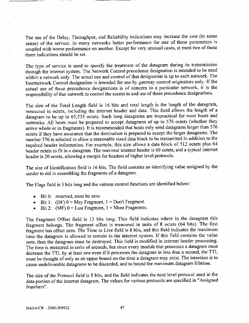
The use of the Delay, Throughput, and Reliability indications may increase the cost (in some
sense) of the service. In many networks better performance for one of these parameters is
coupled with worse performance on another. Except for very unusual cases, at most two of these
three indications should be set.
The type of service is used to specify the treatment of the datagram during its transmission
through the internet system. The Network Control precedence designation is intended to be used
within a network only. The actual use and control of that designation is up to each network. The
Internetwork Control designation is intended for use by gateway control originators only. If the
actual use of these precedence designations is of concern to a particular network, it is the
responsibility of that network to control the access to and use of those precedence designations.
The size of the Total Length field is 16 bits and total length is the length of the datagram,
measured in octets, including the internet header and data. This field allows the length of a
datagram to be up to 65,535 octets. Such tong datagrams are impractical for most hosts and
networks. All hosts must be prepared to accept datagrams of up to 576 octets (whether they
arrive whole or in fragments). It is recommended that hosts only send datagrams larger than 576
octets if they have assurance that the destination is prepared to accept the larger datagrams. Thenumber 576 is selected to allow a reasonable sized data block to be transmitted in addition to the
required header information. For example, this size allows a data block of 512 octets plus 64
header octets to fit in a datagram. The maximal intemet header is 60 octets, and a typical internet
header is 20 octets, allowing a margin for headers of higher level protocols.
The size of Identification field is 16 bits. The field contains an identifying value assigned by the
sender to aid in assembling the fragments of a datagram.
The Flags field is 3 bits long and the various control functions are identified below:
• Bit 0:
• Bit 1:
• Bit 2:
reserved, must be zero
(DF) 0 = May Fragment, 1 = Don't Fragment.
(MF) 0 = Last Fragment, 1 = More Fragments.
The Fragment Offset field is 13 bits long. This field indicates where in the datagram this
fragment belongs. The fragment offset is measured in units of 8 octets (64 bits). The first
fragment has offset zero. The Time to Live field is 8 bits, and this field indicates the maximum
time the datagram is allowed to remain in the internet system. If this field contains the value
zero, then the datagram must be destroyed. This field is modified in internet header processing.
The time is measured in units of seconds, but since every module that processes a datagram must
decrease the TTL by at least one even if it processes the datagram in less than a second, the TTL
must be thought of only as an upper bound on the time a datagram may exist. The intention is to
cause undeliverable datagrams to be discarded, and to bound the maximum datagram lifetime.
The size of the Protocol field is 8 bits, and the field indicates the next level protocol used in the
data portion of the internet datagram. The values for various protocols are specified in "Assigned
Numbers".
NASA/CR--2000-209922 47

TheHeaderChecksumfield is 16bits longanda usedto carry thechecksumon the header only.
Since some header fields change (e.g., time to live), this is recomputed and verified at each point
that the internet header is processed.
The Source Address field is 32 bits long and carries the source address. The Destination Address
field is 32 bits long and carries the destination address.
The Options field is variable and it may or may not appear in datagrams. It must be implemented
by all IP modules (host and gateways). What is optional is its transmission in any particular
datagram, not its implementation. In some environments the security option may be required in
all datagrams. The option field is variable in length. There may be zero or more options. There
are two cases for the format of an option:
• A single octet of option-type.
• An option-type octet, an option-length octet, and the actual option-data octets.
The option-length octet counts the option-type octet and the option-length octet as well as the
option-data octets. The option-type octet is viewed as having 3 fields:
• 1 bit = copied flag,
• 2 bits = option class,
• 5 bits = option number.
The copied flag indicates that this option is copied into all fragments on fragmentation.
• 0=notcopied
• 1 -- copied
The option classes are:
• 0=control
• 1 = reserved for future use
* 2 = debugging and measurement
• 3 = reserved for future use "
Security option provides a way for hosts to send security, compartmentation, handling
restrictions, and TCC (closed user group) parameters. The format for this option is as follows:
Type = 130, Length = 11, and Security (S field) = 16 bits. The field specifies one of 16 levels of
security (eight of which are reserved for future use):
00000000 00000000- Unclassified
11110001 00110101- Confidential
01111000 10011010-EFTO
10111100 01001101-MMMM
00110101 11100010 - Reserved for future use)
10011010 11110001 - (Reserved for future use)
01001101 01111000 - (Reserved for future use)
00100100 10111101 - (Reserved for future use)
NASA/CR--2000-209922 48
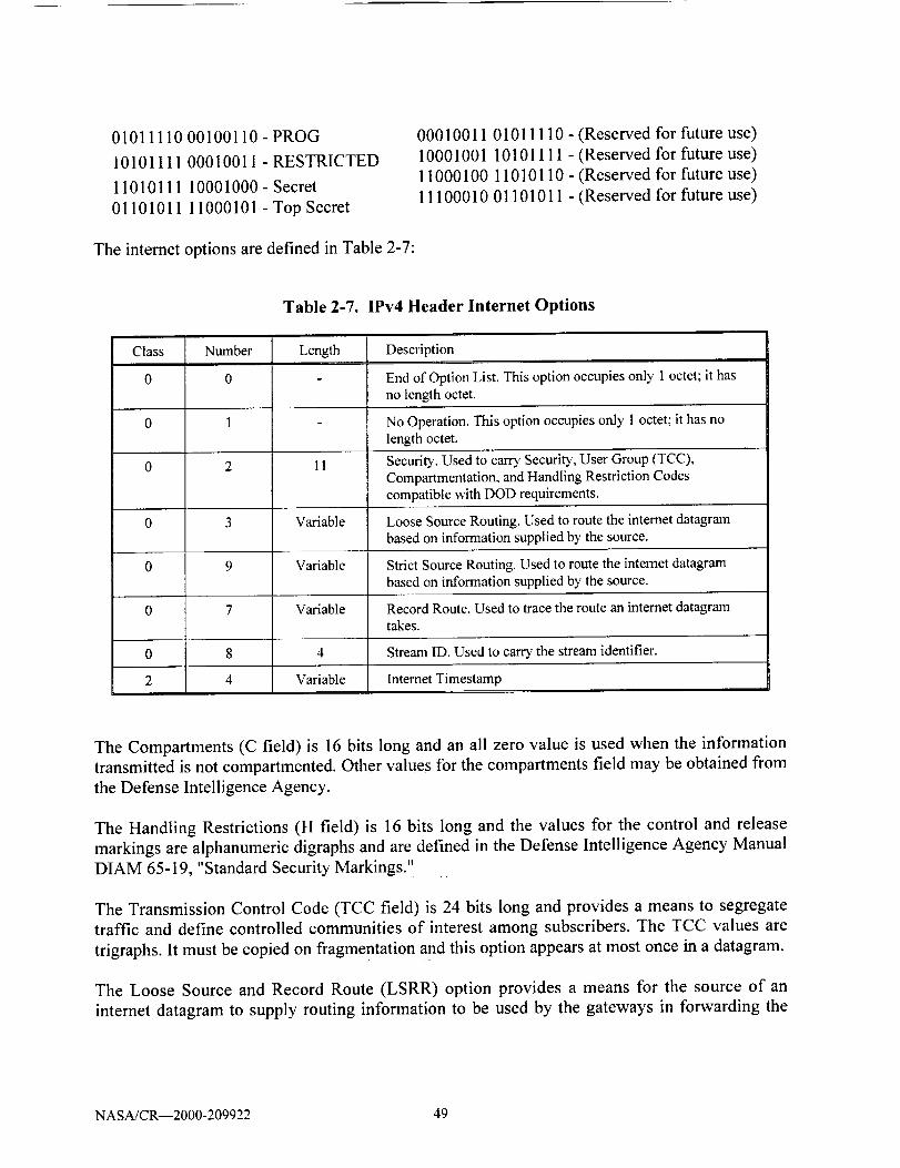
01011110 00100110- PROG
10101111 00010011- RESTRICTED
11010111 10001000-Secret
01101011 11000101-Top Secret
The internet options are defined in Table 2-7:
00010011 01011110 - (Reserved for future use)
10001001 10101111 - (Reserved for future use)
11000100 11010110 - (Reserved for future use)
11100010 01101011 - (Reserved for future use)
Table 2-7. IPv4 Header Internet Options
Class Number Length
11
Variable
Variable
Description
End of Option List. This option occupies only 1 octet; it hasno length octet.
No Operation. This option occupies only 1 octet; it has nolength octet.
Security. Used to can3' Security, User Group (TCC),Compartmentation, and Handling Restriction Codescompatible with DOD requirements.
Loose Source Routing. Used to route the internet datagrambased on information supplied by the source.
Strict Source Routing. Used to route the intemet datagrambased on information supplied by the source.
0 7 Variable Record Route. Used to trace the route an intemet datagramtakes.
0 8 4 Stream ID. Used to can'),' the stream identifier.
2 4 Variable Internet Timestamp
The Compartments (C field) is 16 bits long and an all zero value is used when the information
transmitted is not compartmented. Other values for the compartments field may be obtained from
the Defense Intelligence Agency.
The Handling Restrictions (H field) is 16 bits long and the values for the control and release
markings are alphanumeric digraphs and are defined in the Defense Intelligence Agency Manual
DIAM 65-19, "Standard Security Markings."
The Transmission Control Code (TCC field) is 24 bits long and provides a means to segregatetraffic and define controlled communities of interest among subscribers. The TCC values are
trigraphs. It must be copied on fragmentation and this option appears at most once in a datagram.
The Loose Source and Record Route (LSRR) option provides a means for the source of an
intemet datagram to supply routing information to be used by the gateways in forwarding the
NASA/CR--2000-209922 49

datagram to the destination, and to record the route information. This option begins with the
option type code. The second octet is the option length which includes the option type code and
the length octet, the pointer octet, and length-3 octets of route data. The third octet is the pointer
into the route data indicating the octet that begins the next source address to be processed. The
pointer is relative to this option, and the smallest legal value for the pointer is 4.
The Strict Source and Record Route (SSRR) option provides a means for the source of an
internet datagram to supply routing information to be used by the gateways in forwarding the
datagram to the destination, and to record the route information. The option begins with the
option type code. The second octet is the option length which includes the option type code and
the length octet, the pointer octet, and length-3 octets of route data. The third octet is the pointer
into the route data indicating the octet that begins the next source address to be processed. The
pointer is relative to this option, and the smallest legal value for the pointer is 4. A route data is
composed of a series of internet addresses. Each internet address is 32 bits or 4 octets. If the
pointer is greater than the length, the source route is empty (and the recorded route full) and the
routing is to be based on the destination address field.
The Record Route option provides a means to record the route of an internet datagram. This
option begins with the option type code. The second octet is the option length which includes the
option type code and the length octet, the pointer octet, and length-3 octets of route data. The
third octet is the pointer into the route data indicating the octet that begins the next area to store a
route address. The pointer is relative to this option, and the smallest legal pointer value is 4.
This Stream Identifier option provides a way for the 16-bit SATNET stream identifier to be
carried through networks that do not support the stream concept.
The Internet Timestamp is a right-justified, 32-bit timestamp in milliseconds since midnight UT.
If the time is not available in milliseconds or cannot be provided with respect to midnight UT
then any time may be inserted as a timestamp provided the high order bit of the timestamp fieldis set to one to indicate the use of a non-standard value.
The Padding field is of variable length. The internet header padding is used to ensure that the
internet header ends on a 32 bit boundary.
2.5.5. IPv4 Addressing
As with any other network-layer protocol, the IP addressing scheme is integral to the process of
routing IP datagrams through an internetwork. Each IP address has specific components andfollows a basic format. These IP addresses can be subdivided and used to create addresses for
subnetworks. Each host on a TCP/IP network is assigned an unique 32-bit logical address that is
divided into two main parts: a network number and a host number.
The network number identifies a network and must be assigned by the Internet Network
Information Center (InterNIC) if the network is to be part of the Internet. An Internet Service
NASA/CR--2000-209922 50

Provider(ISP)canobtain blocksof network addressesfrom the InterNIC andcan itself assignaddressspaceasnecessary.
The host number identifies a host on a network and is assignedby the local networkadministrator.
2.5.5.1. IP Address Format
The 32-bit IP address is grouped eight bits at a time, separated by dots, and represented in
decimal format (known as dotted decimal notation). Each bit in the octet has a binary weight
(128, 64, 32, 16, 8, 4, 2, 1). The minimum value for an octet is 0, and the maximum value for an
octet is 255.
2.5.5.2. IP Address Classes
IP addressing supports five different address classes: A, B, C, D, and E. Only classes A, B, and Care available for commercial use. As depicted in Figure 2-11, the left-most (high-order) bits
indicate the network class.
4 octets / 32 bits #I
7 bits 24 bits
Class A _ Network Host Host Host
I_ 14 bits =_t_ 16 bits __1
Class B
i_ 21 bits =j< 8 bit_Class C
Figure 2-11. IPv4 Address Classes
NASA/CR--2000-209922 51

2.5.5.3. IP Subnet Addressing
IP networks can be divided into smaller networks called subnetworks (or subnets). Subnetting
provides the network administrator with several benefits, including extra flexibility, more
efficient use of network addresses, and the capability to contain broadcast traffic (a broadcast
will not cross a router). Subnets are under local administration. As such, the outside world sees
an organization as a single network and has no detailed knowledge of the organization's internal
structure
A given network address can be broken up into many subnetworks. For example, 172.16.1.0,
172.16.2.0, 172.16.3.0, and 172.16.4.0 are all subnets within network 171.16.0.0. (All 0s in the
host portion of an address specifies the entire network).
2.5.6. IPv4 Routing
There are several popular intra-domain (interior) and inter-domain (exterior) routing protocols
associated with IPv4. The following are the most popular intra-domain and inter-domain routing
protocols:
O Intradomain: "Routing Information Protocol" (RIP) and "Open Shortest Path First
(OSPF)" are the intradomain routing protocols. RIP is a vector distance protocol while
OSPF is a link-state routing protocol
• Interdomain: "Border Gateway Protocol Version 4" (BGP-4). BGP-4 is a vector distance
routing protocol.
IPv4 routing protocols are dynamic. Dynamic routing calls for routes to be calculated
automatically at regular intervals by software in routing devices. This contrasts with static
routing, where routes are established by the network administrator and do not change until the
network administrator changes them.
2.5.6.1. Open Shortest Path First (OSPF)
OSPF is a routing protocol developed for Internet Protocol (IP) networks by the Interior Gateway
Protocol (IGP) working group of the Internet Engineering Task Force (IETF). The working
group was formed in 1988 to design an IGP based on the shortest path first (SPF) algorithm for
use in the Internet. Similar to the Interior Gateway Routing Protocol (IGRP), OSPF was created
because in the mid-1980s, the Routing Information Protocol (RIP) was increasingly unable to
serve large, heterogeneous internetworks. OSPF has two primary characteristics:
• The first is that the protocol is open, which means that its specification is in the public
domain. The OSPF specification is published as Request For Comments (RFC) 1247.
• The second principal characteristic is that OSPF is based on the SPF algorithm, which
sometimes is referred to as the Dijkstra algorithm. OSPF is a link-state routing protocol
NASA/CR--2000-209922 52

that calls for the sending link-state advertisements (LSAs) to all other routers within the
same hierarchical area. Information on attached interfaces, metrics used, and other
variables is included in OSPF LSAs. As OSPF routers accumulate link-state information,
they use the SPF algorithm to calculate the shortest path to each node.
As a link-state routing protocol, OSPF contrasts with RIP and IGRP, which are distance-vector
routing protocols. Routers running the distance-vector algorithm send all or a portion of their
routing tables in routing-update messages to their neighbors.
SPF Algorithm
The shortest path first (SPF) routing algorithm is the basis for OSPF operations. When a SPF
router is powered up, it initializes its routing-protocol data structures and then waits for
indications from lower-layer protocols that its interfaces are functional. After a router is assured
that its interfaces are functioning, it uses the OSPF Hello protocol to acquire neighbors, which
are routers with interfaces to a common network. The router sends hello packets to its neighbors
and receives their hello packets. In addition to helping acquire neighbors, hello packets also act
as keep-alives to let routers know that other routers are still functional.
2.5.6.2. Routing Information Protocol (RIP)
The Routing Information Protocol (RIP) is a distance-vector protocol that uses hop count as its
metric. RIP is widely used for routing traffic in the global Internet and is an Interior Gateway
Protocol (IGP), which means that it performs routing within a single autonomous system.
Exterior gateway protocols, such as the Border Gateway Protocol (BGP), perform routing
between different autonomous systems. IP RIP is formally defined in two documents: Request
For Comments (RFC) 1058 and 1723. RFC 1058 (1988) describes the first implementation of
RIP, while RFC 1723 (1994) updates RFC 1058. RFC 1058 enables RIP messages to carry more
information and security features.
Routing Updates
RIP sends routing-update messages at regular intervals and when the network topology changes.
When a router receives a routing update that includes changes to an entry, it updates its routing
table to reflect the new route. The metric value for the path is increased by one, and the sender is
indicated as the next hop. RIP routers maintain only the best route (the route with the lowest
metric value) to a destination. After updating its routing table, the router immediately begins
transmitting routing updates to inform other network routers of the change. These updates are
sent independently of the regularly scheduled updates that RIP routers send.
RIP Routing Metric
RIP uses a single routing metric (hop count) to measure the distance between the source and a
destination network. Each hop in a path from source to destination is assigned a hop-count value,
which is typically 1. When a router receives a routing update that contains a new or changed
NASA/CR--2000-209922 53

destination-network entry, the router adds one to the metric value indicated in the update and
enters the network in the routing table, The IP address of the sender is used as the next hop. RIP
prevents routing loops from continuing indefinitely by implementing a limit on the number of
hops allowed in a path from the source to a destination. The maximum number of hops in a path
is 15. If a router receives a routing update that contains a new or changed entry, and if increasing
the metric value by one causes the metric to be infinity (that is, 16), the network destination isconsidered unreachable.
2.5.6.3. Border Gateway Protocol (BGP)
The Border Gateway Protocol (BGP) is an inter-autonomous system routing protocol (1ETF RFC
1654 compliant) for exchanging routing information between gateway hosts (each with its own
router). The primary function of a "BGP speaking system" is to exchange network reachability
information with other BGP systems. BGP-4 provides a set of mechanisms for supporting
classless interdomain routing (CIDR), which effectively extends the IPv4 addressing scheme.
2.5.7. IPv4 & IPv6 Security (IPSec)
IPSec functionality is specified in both the IPv4 and IPv6 protocols. IPSec is a framework of
open standards developed by the Intemet Engineering Task Force (IETF) that provides security
for transmission of sensitive information over unprotected networks such as the Internet. It acts
at the network level and implements the following standards:
• Internet Key Exchange (IKE)
• Authentication Header (AH)
• Encapsulating Security Payload (ESP)
IPSec uses the following terms in describing the capabilities. These are:
• Authentication is property of knowing that the data received is the same as the data that
was sent and that the claimed sender is in fact the actual sender.
• Integrity is property of ensuring that data is transmitted from source to destinationwithout undetected alteration.
• Confidentiality is property of communicating such that the intended recipients know what
was being sent but unintended parties cannot determine what was sent.
• Encryption is a mechanism cornnaonly used to provide confidentiality.
Non-repudiation is property of a receiver being able to prove that the sender of some data
did in fact send the data even though the sender might later desire to deny ever havingsent that data.
NASA/CR--2000-209922 54

SPI is acronym for "Security Parameters Index." An unstructured opaque index which is
used in conjunction with the Destination Address to identify a particular Security
Association.
Security Association is the set of security information relating to a given networkconnection or set of connections. This is described in detail below.
Traffic Analysis is the analysis of network traffic flow for the purpose of deducing
information that is useful to an adversary. Examples of such information are frequency of
transmission, the identities of the conversing parties, sizes of packets, and Flow
Identifiers used.
2.5.7.1. lnternet Key Exchange Security Protocol 0KE)
The Internet Key Exchange (IKE) security protocol is a key management protocol standard that
is used in conjunction with the IPSec standard. IPSec can be configured without IKE, but IKE
enhances IPSec by providing additional features, flexibility, and ease of configuration for the
IPSec standard.
2.5.7.2. IP Authentication Header (AH)
The IP Authentication Header is designed to provide integrity and authentication without
confidentiality to IP datagrams. The lack of confidentiality ensures that implementations of the
Authentication Header will be widely available on the Internet, even in locations where the
export, import, or use of encryption to provide confidentiality is regulated. The Authentication
Header supports security between two or more hosts implementing AH, between two or more
gateways implementing AH, and between a host or gateway implementing AH and a set of hosts
or gateways.
2.5.7.3. IP Encapsulating Security Payload (ESP)
The IP Encapsulating Security Payload (ESP) is designed to provide integrity, authentication,
and confidentiality to IP datagrams. The ESP supports security between two or more hosts
implementing ESP, between two or more gateways implementing ESP, and between a host or
gateway implementing ESP and a set of hosts and/or gateways.
A security gateway is a system which acts as the communications gateway between external
untrusted systems and trusted hosts on their own subnetwork. Ii provides security services for the
trusted hosts when they communicate with external untrusted systems. A trusted subnetwork
contains hosts and routers that trust each other not to engage in active or passive attacks and trust
that the underlying communications channel (e.g., an Ethernet) isn't being attacked.
Trusted systems always should be trustworthy, but in practice they often are not trustworthy.
Gateway-to-gateway encryption is most valuable for building private virtual networks across an
NASA/CR--2000-209922 55
untrusted backbone such as the Intemet. It does this by excluding outsiders. As such, it is often
not a substitute for host-to-host encryption, and indeed the two can be and often should be used
together. In the case where a security gateway is providing services on behalf of one or more
hosts on a trusted subnet, the security gateway is responsible for establishing the security
association on behalf of its trusted host and for providing security services between the security
gateway and the external system(s). In this case, only the gateway need implement ESP, while all
of the systems behind the gateway on the trusted subnet may take advantage of ESP services
between the gateway and external systems.
A gateway which receives a datagram containing a recognized sensitivity label from a trusted
host should take that label's value into consideration when creating/selecting a Security
Association for use with ESP between the gateway and the external destination. In such an
environment, a gateway which receives a IP packet containing the ESP should appropriately
label the decrypted packet that it forwards to the trusted host that is the ultimate destination.
2.5.7.4. Combining Security Mechanisms
In some cases the IP Authentication Header might be combined with the IP Encapsulating
Security Protocol to obtain the desired security properties. The Authentication Header always
provides integrity and authentication and can provide non-repudiation if used with certain
authentication algorithms (e.g., RSA). The Encapsulating Security Payload always provides
integrity and confidentiality and can also provide authentication if used with certain
authenticating encryption algorithms. Adding the Authentication Header to a IP datagram prior
to encapsulating that datagram using the Encapsulating Security Protocol might be desirable for
users wishing to have strong integrity, authentication, confidentiality, and perhaps also for users
who require strong non-repudiation. When the two mechanisms are combined, the placement of
the IP Authentication Header makes clear which part of the data is being authenticated.
2.5.8. IPv4 & IPv6 Mobility (Mobile IP)
Both IPv4 and IPv6 incorporate mobility related features and functionality within the protocol.
Mobile IP provides an efficient, scalable mechanism for node mobility within the Internet. Using
Mobile IP, nodes may change their point-of-attachment to the Internet without changing their IP
address. This allows them to maintain transport and higher-layer connections while moving.
Node mobility is realized without the need to propagate host-specific routes throughout the
Internet routing fabric.
Packets destined to a mobile node are routed first to its home network - a network identified by
the network prefix of the mobile node's (permanent) home address. At the home network, the
mobile node's home agent intercepts such packets and tunnels them to the mobile node's most
recently reported care-of address. At the endpoint of the tunnel, the inner packets are
decapsulated and delivered to the mobile node. In the reverse direction, packets sourced by
mobile nodes are routed to their destination using standard IP routing mechanisms.
NASA/CR--2000-209922 56

Thus, Mobile IP relies on protocol tunneling to deliver packets to mobile nodes that are awayfrom their home network. The mobile node's home address is hidden from routers along the path
due to the presence of the tunnel. The encapsulating packet is destined to the mobile node's care-
of address - a topologically significant address - to which standard IP routing mechanisms can
deliver packets.
The capabilities supported by Mobile IP protocol include:
• An authenticated registration procedure by which a mobile node informs its home
agent(s) of its care-of address(es).
• An extension to ICMP Router Discovery [RFC 1256] which allows mobile nodes to
discover prospective home agents and foreign agents.
The rules for routing packets to and from mobile nodes, including the specification of one
mandatory tunneling mechanism ([MIP-IPinlP]) and several" optional tunneling
mechanisms ([MIP-MINENC] and [RFC 1701]).
Mobile IP mandates the use of cryptographically strong authentication for all registration
messages exchanged between a mobile node and its home agent. Optionally, strongauthentication can be used between foreign agents and mobile nodes or home agents. Replay
protection is realized via one of two possible mechanisms -- timestamps or other techniques.
Due to the unavailability of an Internet key management protocol, agent discovery messages are
not required to be authenticated. All Mobile IP implementations are required to support, at a
minimum, keyed MD5 authentication with manual key distribution. Other authentication and key
distribution algorithms may be supported. Mobile IP defines security mechanisms only for the
registration protocol. Implementations requiring privacy and/or authentication of data packets
sent to and from a mobile node should use the IP security protocols described in RFCs 1827 and
1826 for this purpose.
2.5.9. IPv4 and IPv6 QoS
Today's Internet is basically a "best effort" service. A packet, with a destination address, ishanded offto a IP router and the router will deliver each packet. However, new routers are being
introduced by the major manufactures that provide QoS, but this is an exception rather than the
rule for today's Internet. New applications are being introduced for today's Internet that require
QoS. The primary application is Voice over IP (VoIP) and video. VoIP and video have very
specific latency, bandwidth and "jitter" requirements".
2.5.9.1. QoS Signaling
Think of QoS signaling as a form of network communication. It provides a way for an end
station or a network element to signal certain requests to a neighbor. For example, an IP network
NASA/CR--2000-209922 57
canusepart of the IP packet header to request special handling of priority or time-sensitive
traffic. QoS signaling is useful for coordinating the traffic handling techniques and has a key role
in configuring successful end-to-end QoS across a network.
True end-to-end QoS requires that every element in the network path - switch, router, firewall,
host, client, and so on - deliver its part of QoS, and it all must be coordinated with QoS
signaling. However, the challenge is finding a robust QoS signaling solution that can operate
end-to-end over heterogeneous network infrastructures. Although many viable QoS signaling
solutions provide QoS at some places in the infrastructure, they often have limited scope acrossthe network.
This section focuses on IP precedence and RSVP because both of these methods take advantage
of the end-to-end nature of IP. As the majority of applications converge on the use of IP as the
primary networking protocol, IP precedence and RSVP provide a powerful combination for QoS
signaling - IP precedence signals for differentiated QoS, and RSVP for guaranteed QoS.
2.5.9.2. IP Precedence: Signaling Differentiated QoS
IP precedence uses the three precedence bits in the IPv4 header's ToS (Type of Service) field to
specify class of service for each packet. Traffic can be partitioned into up to six classes of service
using IP precedence (two others are reserved for internal network use). The queuing techniques
throughout the network can then use this signal to provide the appropriate expedited handling.
Features used to set precedence are based on extended access-list classification. This allows
considerable flexibility for precedence assignment, including assignment by application or user,
or by destination and source subnet. Typically this functionality is deployed as close to the edge
of the network (or administrative domain) as possible so that each subsequent network element
can provide service based on the determined policy.
IP precedence can also be set in the host or network client, and this signaling can be used
optionally. However, this can be overridden by policy within the network. IP precedence enables
service classes to be established using existing network queuing mechanisms with no changes to
existing applications or complicated network requirements. Note that this same approach is
easily extended to IPv6 using its Priority field.
2.5.9.3. Guaranteeing QoS
RSVP is an IETF Internet Standard (RFC 2205) protocol, for allowing an application to
dynamically reserve network bandwidth. RSVP enables applications to request a specific QoS
for a data flow. Network managers can thereby take advantage of the benefits of RSVP in the
network, even for non-RSVP-enabled applications and hosts.
NASA/CR--2000-209922 58
2.6. IPv6 Protocol Overview
IP version 6 (IPv6) is a new version of the Internet Protocol, designed as the successor to IP
version 4 (IPv4). The changes from IPv4 to IPv6 fall primarily into the following categories:
Expanded Addressing Capabilities: IPv6 increases the IP address size from 32 bits to 128
bits, to support more levels of addressing hierarchy, a much greater number of
addressable nodes, and simpler auto-configuration of addresses. The scalability of
multicast routing is improved by adding a "scope" field to multicast addresses. A new
type of address called an "anycast address" is defined; it is used to send a packet to any
one of a group of nodes.
Header Format Simplification: Some IPv4 header fields have been dropped or made
optional, to reduce the common-case processing cost of packet handling and to limit thebandwidth cost of the IPv6 header.
Improved Support for Extensions and .Options: Changes in the way IP header options are
encoded allows for more efficient forwarding, less stringent limits on the length of
options, and greater flexibility for introducing new options in the future.
Flow Labeling Ca_: A new capability is added to enable the labeling of packets
belonging to particular traffic "flows" for which the sender requests special handling,
such as non-default quality service or "real-time" service. Authentication and Privacy
Capabilities Extensions to support authentication, data integrity, and (optional) data
confidentiality are specified for IPv6.
The IPv6 protocol represents the evolution of many different Internet Engineering Task Force
(IETF) proposals and working groups focused on developing an IPng (IP _ Next Generation). By
the Winter of 1992 the Internet community had developed four separate proposals for IPng.
These were "CNAT," "IP Encaps," "Nimrod", and "Simple CLNP." By December 1992 three
more proposals followed; "The P Internet Protocol" (PIP), "The Simple Internet Protocol" (SIP)
and "TP/IX." In the Spring of 1992 the "Simple CLNP" evolved into "TCP and UDP with Bigger
Addresses" (TUBA) and "IP Encaps" evolved into "IP Address Encapsulation" (IPAE).
By the fall of 1993, IPAE merged with SIP while still maintaining the name SIP. This group later
merged with PIP and the resulting working group called themselves "Simple Internet Protocol
Plus" (SIPP). At about the same time the TP/IX Working Group changed its name to "Common
Architecture for the Interact" (CATNIP). The IPv6 area directors made a recommendation for an
IPv6 in July of 1994. This recommendation, included the following elements:
• Current address assignment policies are adequate.
• There is no current need to reclaim underutilized assigned network numbers.
• There is no current need to renumber major portions of the Internet.
NASA/CR--2000-209922 59

• CIDR-style assignments of parts of unassigned Classconsidered.
• Support for the Authentication Header be required.
• Support for a specific authentication algorithm be required.
• Support for the Privacy Header be required.
• Support for a specific privacy algorithm be required.
• An "lPv6 framework for firewalls" be developed.
A address space should be
2.6.1. Header Format Simplification
Some IPv4 header fields have been dropped or made optional to reduce the common-case
processing cost of packet handling and to keep the bandwidth cost of the IPv6 header as low as
possible despite the increased size of the addresses. Even though the IPv6 addresses are four
times longer than the IPv4 addresses, the IPv6 header is only twice the size of the IPv4 header.
The IPv6 protocol stack is the heir-apparent successor to IPv4. The primary reason for migrating
to IPv6 from IPv4 is the critical lack of available address space for new devices. IPv6 changes
the number of available address to 128 bits from 32 bits for IPv4. However, many other features
besides expanded addressing, are integrated into the basic functionality of IPv6 such as:
• Simplified header format
• Improved extension and options support
• Flow labeling
• Authentication
2.6.2. IPv6 Transport Layer
Both the connectionless (UDP) and connection-oriented (TCP) transport protocols can be used
with IPv6. TCP is a connection oriented transport layer protocol defined originally as
Transmission Control Protocol and UDP is a connectionless transport layer protocol defined
originally as User Datagram Protocol.
2.6.3. IPv6 Network Layer
RFC 1833 titled "Intemet Protocol, Version 6 (IPv6) Specification" specifies the IPv6 and forms
the network layer in the TCP/IP protocol architecture.
NASA/CR--2000- 209922 60
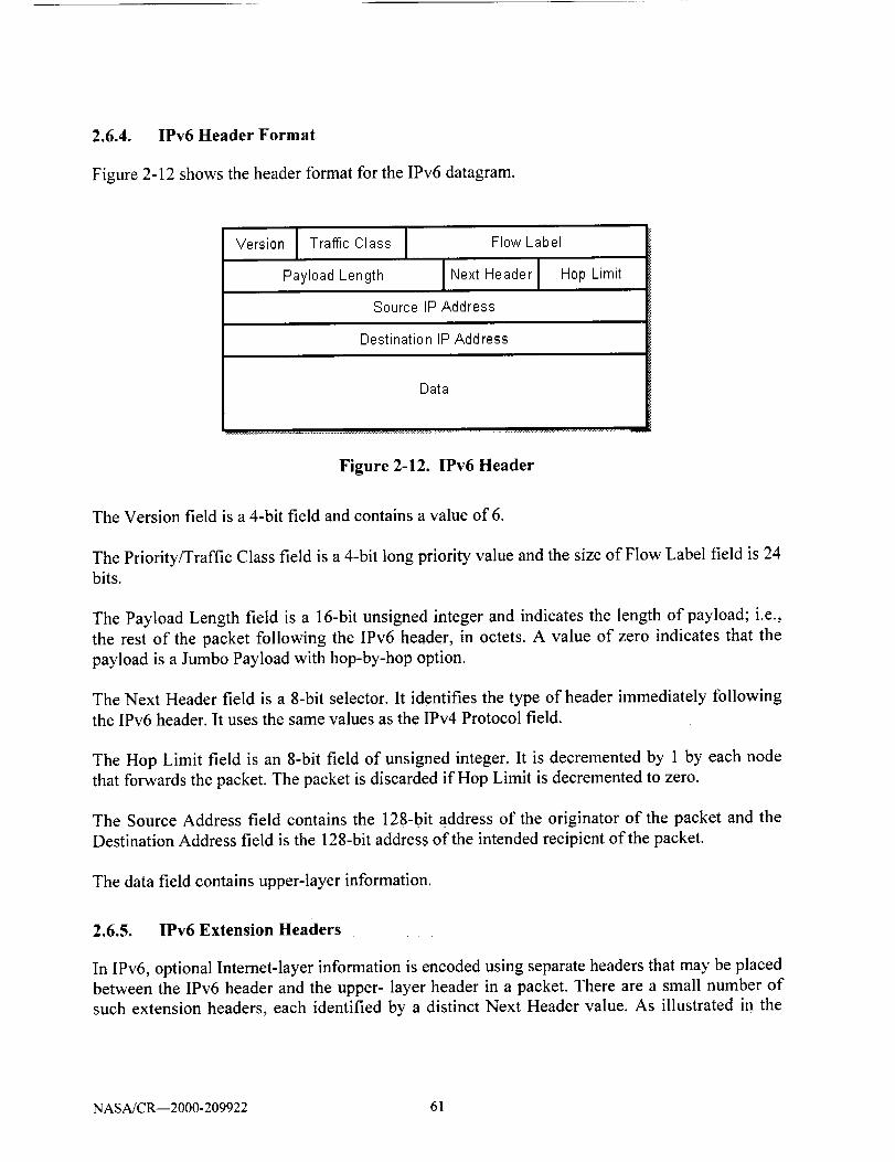
2.6.4. IPv6 Header Format
Figure 2-12 shows the header format for the IPv6 datagram.
Version [ Traffic Class I
Payload Length
Flow Label
I Next Header I Hop Lirnit
Source IP Address
Destination IP Address
Data
Figure 2-12. IPv6 Header
The Version field is a 4-bit field and contains a value of 6.
The Priority/Traffic Class field is a 4-bit long priority value and the size of Flow Label field is 24bits.
The Payload Length field is a 16-bit unsigned integer and indicates the length of payload; i.e.,
the rest of the packet following the IPv6 header, in octets. A value of zero indicates that the
payload is a Jumbo Payload with hop-by-hop option.
The Next Header field is a 8-bit selector. It identifies the type of header immediately following
the IPv6 header. It uses the same values as the IPv4 Protocol field.
The Hop Limit field is an 8-bit field of unsigned integer. It is decremented by 1 by each node
that forwards the packet. The packet is discarded if Hop Limit is decremented to zero.
The Source Address field contains the 128-bit address of the originator of the packet and the
Destination Address field is the 128-bit address of the intended recipient of the packet.
The data field contains upper-layer information.
2.6.5. IPv6 Extension Headers
In IPv6, optional Internet-layer information is encoded using separate headers that may be placed
between the IPv6 header and the upper- layer header in a packet. There are a small number of
such extension headers, each identified by a distinct Next Header value. As illustrated in the
NASA/CR--2000-209922 61

Figure2-13 an IPv6 packetmay carry zero,one,or moreextensionheaders;eachidentified bytheNext Headerfield of theprecedingheader.
IPv6header _i IPv6 Header _' IPv6HeaderNext Header= TCP Next Header= Routing Next Header= Fragment
TCP Header
Remainder of Packet
IPv6Routing HeaderNext Header = TCP
TCP Header
Remainder of Packet
Fragment HeaderNext Header= Auth
Authentication HeaderNext Header= ESP
ESP HeaderNext Header= TCP
TCP Header
Remainder of Packet
Figure 2-13. Three Examples of IPv6 Packets with Extension Headers
With one exception, extension headers are not examined or processed by any node along a
packet's delivery path, until the packet reaches the node (or each of the set of nodes, in the case
of multicast) identified in the Destination Address field of the IPv6 header. A short description of
each extension header is presented below.
Hop-by-Hop Header The Hop-by-Hop Options header is used to carry optional
information that must be examined by every node along a packet's delivery path. The
Hop-by-Hop Options header is identified by a Next Header value of 0 in the IPv6 header.
So far the only option that has been specified by the Internet community is the jumbo
payload options. This option will allow payloads larger than 65,535 bytes.
Routing Header (RH) The Routing header is used by an IPv6 source to list one or more
intermediate nodes to be "visited" on the way to a packet's destination. This function is
very similar to IPv4's Source Route options. The Routing header is identified by a Next
Header value of 43 in the immediately preceding header.
• Fragment Header (FH) The Fragment header is used by an IPv6 source to send packets
larger than would fit in the path MTU to their destinations. (Note: Unlike with IPv4, only
NASA/CR--2000-209922 62

source nodes perform fragmentation in IPv6. Fragmentation is not performed by routers
along a packet's delivery path.) The Fragment header is identified by a Next Header value
of 44 in the immediately preceding header.
Destination Options Header The Destination Options header is used to carry optional
information that need be examined only by a packet's destination node(s). The
Destination Options header is identified by a Next Header value of 60 in the immediately
preceding header.
- At present the only destination options header specified are padding options to fill out
the header on a 64-bit boundary if (future) options require it.
Authentication Header (AH)The Authentication Header provides a mechanism for
calculating a cryptographic checksum on some part of the IPv6 header, extension
headers, and payload.
Encapsulating Security Payload Header (ESP)This header will always be the last,
unencrypted header of any packet. It indicates that the rest of the payload is encrypted,
and provides enough information for the authorized destination node to decrypt it.
2.6.6. IPv6 Routing Protocols
Following in IPv4's footsteps, IPv6 uses similar interior (intra-domain) and exterior (inter-
domain) routing protocols. The only additional routing protocol specified for IPv6 is IDRP.
Intradomain: Routing Information Protocol Next Generation (RiPng) as described by
RFC 2080 and Open Path Shortest First Version 2 (OSPFv2) as described in RFC 2328.
RIP is a vector distance protocol while OSPF is a link state routing protocol.
Interdomain: Border Gateway Protocol Version 4 (BGP-4) BGP-4 is a vector distance
routing protocol. The other routing protocol for IPv6 is Inter-Domain Routing Protocol
(IDRP). IDRP is based loosely on BGP-4.
2.6.7. IPv6 Addressing
IPv6 addresses are 128-bit identifiers for interfaces and sets of interfaces. There are three types
of addresses: Unicast, Anycast, and Multicast The leading bits in the address indicate the specific
type of an IPv6 address. Referring to Figure 2-14, the variable-length field comprising these
leading bits is called the Format Prefix (FP) which is a 3-bit field. The addressing architecture
(RFC 2373) defines an address FP of 001 (binary) for aggregatable global unicast addresses. Thesame address format could be used for other Format Prefixes, as long as these Format Prefixes
also identify IPv6 unicast addresses.
NASA/CR--2000-209922 63

t6 octets / 128 bits
4 '=v
FPFormatPrefix
3 bits
TI,.A ID
Top-LevelAggregation
Identifier
13 bits
RE$
Reservedfor future use
8 bits
NLA ID SLA ID
Next-Level Site-LevelAggregation Aggregation
Identifier Identifier
24 bits 16 bits
Intertace IDInterfaceIdentifier
64 bits
Figure 2-14. IPv6 Aggregatable Global Unicast Address Format
IPv6 unicast addresses are designed assuming that the Internet routing system makes forwarding
decisions based on a "longest prefix match" algorithm on arbitrary bit boundaries and does not
have any knowledge of the internal structure of IPv6 addresses. The structure in IPv6 addresses
is for assignment and allocation. The only exception to this is the distinction made betweenunicast and multicast addresses.
This address format is designed to support both the current provider-based aggregation and a
new type of exchange-based aggregation. The combination will allow efficient routing
aggregation for sites that connect directly to providers and for sites that connect to exchanges.
Sites will have the choice to connect to either type of aggregation entity.
While this address format is designed to support exchange-based aggregation (in addition to
current provider-based aggregation) it is not dependent on exchanges for it's overall route
aggregation properties. It will provide efficient route aggregation with only provider-based
aggregation. Aggregatable addresses are organized into a three level hierarchy:
• Public topology is the collection of providers and exchanges that provide public Internettransit services.
• Site topology is local to a specific site or organization that does not provide public transitservice to nodes outside of the site.
• Interface identifiers identify interfaces on links.
The aggregatable global unicast address fields are defined as follows:
Format Prefix (FP) is the three bit prefix to the iPv6 address that identifies where it
belongs in the IPv6 address space. Currently, 001 in this field identifies it as an
aggregatable global address.
NASA/CR--2000-209922 64

Top-Level Aggregation Identifier (TLA ID) is the top level in the routing hierarchy.
Default-free routers must have a routing table entry for every active TLA ID and will
probably have additional entries providing routing information for the TLA ID in which
they arelocated. They may have additional entries in order to optimize routing for their
specific topology. However, the routing topology at all levels must be designed tominimize the number of additional entries fed into the default free routing tables.
This addressing format supports 8,192 (2"13) TLA IDs. Additional TLA IDs may be
added by either growing the TLA field to the right into the reserved field or by using
this format for additional format prefixes.
The Reserved (RES)field is reserved for future use and must be set to zero. The
Reserved field allows for future growth of the TLA and NLA fields, as appropriate.
Next-Level Aggregation Identifiers (NLA IDs) are used by organizations assigned a TLA
ID to create an addressing hierarchy and to identify sites. The organization can assign the
top part of the NLA ID in a manner to create an addressing hierarchy appropriate to its
network. It can use the remainder of the bits in the field to identify sites it wishes to
serve.
The Site-Level Aggregation Identifier (SLA ID) is used by an individual organization to
create its own ID field. It is the responsibility of the individual organization. The number
of subnets supported in this address format should be sufficient for all but the largest of
organizations. Organizations which need additional subnets can arrange with the
organization they are obtaining Internet service from to obtain additional site identifiersand use this to create additional subnets.
Interface identifiers (Interface IDs) are used to identify interfaces on a link. They are
required to be unique on that link. They may also be unique over a broader scope. In
many cases an interface identifier will be the same or be based on the interface's link-
layer address. Interface IDs used in the aggregatable global unicast address format are
required to be 64 bits long and to be constructed in IEEE EUI-64 format [EUI-64].
2.6.8. IPv6 Routing
BGP-4 and IDRP are likely to continue as the exterior routing protocols of choice for IPv6, with
relatively few modifications to support IPv6 addresses and address scopes. For interior routing
protocols, OSPF version 2 (RFC 2328) and RIPng as described in RFC 2080 will most likely
succeed as the interior routing protocols of choice for IPv6.
NASA/CR--2000-209922 65

2.6.9. IPv6 and NSAP addresses
With the IPv6 addressing method it is possible to map NSAP addresses to the new IPv6 address.
In contrast, the IPv4 addressing structures must be accommodated for NSAP addresses by using
an encapsulation or conversion technique.
2.7. ATN and TCP/IP Architecture and Protocol Comparison
Figure 2-15 presents the ATN protocol architecture. It consists of the application layer that
interfaces to the application processes. ATN application processes communicate using the
application entity (AE). The application layer interfaces to the upper layer communications
service that consists of the standard OSI upper layer session and presentation protocols that offer
added value on top of the transport service. The upper layer communications protocols interface
to the internet communications service that consists of the OSI transport and network layers. The
network layer in the internet communication service interfaces to various subnetworks. In ATN
the subnetworks can be air-to-ground or ground-to-ground networks.
ApplicationLayer
Fast Byte COF'Pand COSP
TransportLayer (TP4)
Network
Layer (0LNP)
1
Ait=Gr°und I [Subnetwork
Ground-Groundl I
Subnetwork J I
Figure 2-15. ATN Protocol Architecture
NASA/CR--2000-209922 66

2.7.1. ATN and TCP/IP Protocol Architecture
ATN application processes communicate using the application entity (AE) in the ATN protocol
stack. Upper layer communications service consists of the standard OSI upper layer session and
presentation protocols that offer added value on top of the transport service. The internetcommunications service consists of the OSI transport and network layers.
In an air-ground networking environment bandwidth efficiency is very important. In ATN
bandwidth efficiency is achieved by using the concept of Fast Byte. In the fast byte architecture
the protocol control information (PCI) in the presentation and session layers of the OSI protocol
architecture are replaced by a byte each in the two layers. In addition these functions are moved
to the application layer.
With the Fast byte COPP and COSP replacing the OSI presentation and session layers and then
moving this functionality into the application layer produces a protocol architecture where the
application layer interfaces directly to the transport service. In ATN, TP4/CLNP protocols
provide the transport service. The resulting protocol architecture is similar to the TCP/IP
protocol architecture except that the transport service is provide by the TCP/IP protocols.
Figure 2-16 shows the ATN and TCP/IP protocol architectures supporting application layer
which is common to both architectures. Similarly the subnetworks are also common to both
architectures.
Application
Layer with Fast ByteCOPP and COSP
TransportLayer (TP4)
NetworkLayer (0LNP)
TransportLayer (TCP)
NetworkLayer (IPv6)
II 1IAir-Ground Ground-GroundSubnetwork Subnetwork
Figure 2-16. ATN and TCP/IP Architecture
NASA/CR--2000-209922 67

2.7.2. Transport Service
The transport layer is the basic end-to-end building block of end system communication.
Everything above the transport layer is associated with distributed application and everything
below the transport layer is transmission network oriented. In ATN, TP4 provides a reliable data
path for the upper layers as part of a connection oriented service. The Connection Less Transport
Protocol (CLTP) provides simple datagram delivery as part of a connectionless service. In the
TCP/IP protocol suite, reliable connection oriented service is provided by TCP and the simple
datagram service by the User Datagram Protocol UDP.
In a connection oriented operation, the data stream submitted to the transport layer by the source
transport user must be delivered to the destination transport user without loss. There may not be
duplication of any of the octets in the data stream, and the octets must be delivered in the same
order as that in which they were submitted. The transport layer must also provide end-to-end
detection and recovery to identify and correct error introduced into the data stream by thenetwork.
In both connection oriented and connectionless modes, the transport layer must do what it can to
optimize the use of the network's resources for a given quality of service objectives specified by
the transport users.
2.7.3. ATN Connection Oriented Transport Protocol
ATN (OSI) transport layer identifies the functions associated with the connection oriented
transport service (COTS) and the following end-to-end functions are elements of the connection
oriented transport service:
• Multiplexing of connections onto network connections (and demultiplexing them at the
destination).
• Sequence control to preserve the order of transport service data units submitted to the
transport layer.
• Segmenting transport service data units into multiple transport protocol data units (and
reassembling of the original transport service data units at the destination).
• Blocking multiple transport service data units into a single transport protocol data unit
(and unblocking it into the original transport service data units at the destination).
Concatenating multiple transport protocol data units into a single network service data
unit (NSDU) (and separating into the individual transport protocol data units at the
destination).
NASA/CR--2000-209922 68

Error detectionto ensure that any difference between the data submitted to the transport
layer at the source and data that arrive at the destination is detected.
Error recovery to take appropriate action when errors are discovered by the error
detection function.
Flow control to regulate the amount and pacing of data transferred between transport
entities and between the adjacent session and transport layers.
Expedited data transfer to permit certain transport service user data to bypass normal data
flow control (Similar to the urgent data in TCP).
2.7.4. TCP/IP Reliable Stream Service
In the TCP/IP protocol architecture, TCP provides a reliable connection oriented transport
service. RFC 793 describes TCP as providing robustness in spite of unreliable communications
media and data transfer that is reliable, ordered, full duplex, and flow controlled. The end-to-end
transport service functions supported by TCP are:
• Multiplexing of multiple pairs of processes with upper layer protocols.
• Sequence control to preserve the order of octets submitted to TCP.
• Flow control to regulate the flow of data across the transport connection.
• Push whereby a sending upper layer protocol process can force both sending and
receiving TCP processes to deliver data to the receiving upper layer protocol process.
• Urgent data, an interrupt data service whereby a sending upper layer protocol process
may request that data marked urgent be processed quickly by the receiving upper layer
protocol process.
2.7.5. TP4 and TCP Transport Services
The transport service provided by TP4 and TCP are functionally equivalent. In addition, by
examining the process of establishing a transport connection, providing reliable data transfer
through retransmission on time out mechanisms and connection termination of each protocol
shows they are operationally similar as well. The comparison shown in Table 2-8 is based on the
study performed by the U.S. Defense Communication Agency (DCA, now DISA) and the
National Academy of Sciences concluded that TCP and TP4 are functionally equivalent and
provide essentially similar services.
NASA/CR--2000-209922 69

Table 2-8. Comparison of TCP and TP4 Functions
Function TCP Protocol TP4 Protocol
Data transfer Streams Blocks
Flow control Octets Segments
Error detection Checksum Checksum
Error correction Retransmission Retransmission
Addressing 16 bit ports Variable TSAP address
Interrupt service Urgent data Expedited data
Security Supported Variable in TP
Precedence Supported 16 bits in TP
Connection termination Graceful Non graceful
2.8. Network Service
At the network layer ISO supports the Connectionless Network Protocol (CLNP) and the TCP/IP
protocol architecture supports IP. The CLNP and IP are functionally identical and both are best
effort delivery network protocols. The major difference between the two is that CLNP
accommodates variable length addresses, whereas IPv4 supports fixed 32-bit addresses, IPv6
supports 128-bit addresses.
The Internet Control Message Protocol (ICMP) provides elaborate mechanisms for reporting
errors in IP datagram processing at hosts and gateways. Equivalent functions are provided for
CLNP using a reason for discard option conveyed in the CLNP error report. Both CLNP and IP
have multiple options. The sets of options defined for the two protocols are virtually identical,
but the processing is slightly different.
ICMP defines messages other than error reports. The source quench message serves as a coarse
congestion notification mechanism, providing routers with a means to tell hosts to reduce the rate
at which they are sending IP packets. The same function is accomplished in OSI using a CLNP
error report with the reason for discard field set to the value that means congestion experienced.
Table 2-9 compares the functions of CLNP with those of IP.
NASA/CR--2000-209922 70
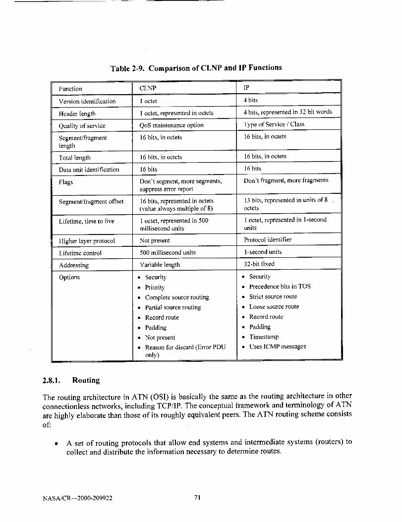
Table 2-9. Comparison of CLNP and IP Functions
Function CLNP IP
Version identification 1 octet 4 bits
Header length 1 octet, represented in octets 4 bits, represented in 32 bit words
Quality of service QoS maintenance option Type of Service / Class
Segment/fragment 16 bits, in octets
length
Total length 16 bits, in octets
Data unit identification 16 bits
Flags Don't segment, more segments,suppress error report
Segment/fragment offset 16 bits, represented in octets(value always multiple of 8)
Lifetime, time to live 1 octet, represented in 500millisecond units
Higher layer protocol Not present
16 bits, in octets
16 bits, in octets
16 bits
Don't fragment, more fragments
13 bits, represented in units of 8octets
I octet, represented in l-secondunits
Protocol identifier
Lifetime control 500 millisecond units 1-second units
Addressing Variable length 32-bit fixed
Options • Security
• Priority
• Complete source routing
• Partial source routing
• Record route
• Padding
• Not present
• Reason for discard (Error PDU
only)
• Security
• Precedence bits in TOS
• Strict source route
• Loose source route
• Record route
• Padding
• Timestamp
• Uses ICMP messages
2.8.1. Routing
The routing architecture in ATN (OSI) is basically the same as the routing architecture in other
connectionless networks, including TCP/IP. The conceptual framework and terminology of ATN
are highly elaborate than those of its roughly equivalent peers. The ATN routing scheme consists
of:
• A set of routing protocols that allow end systems and intermediate systems (routers) to
collect and distribute the information necessary to determine routes.
NASA/CR--2000-209922 71

• A routing base containing this information from which routes between end systems can
be computed.
• A routing algorithm that uses the information contained in the routing information base to
derive routes between end systems.
In order to optimize the resources required to effectively route data packets in a global internet,
ATN routing uses a hierarchical architecture and is divided into three functional tiers:
• End-system to intermediate system routing in which the principal routing functions is
discovery and redirection.
lntra-domain intermediate system to intermediate system routing (router to router) in
which best routes between ESs within a single administrative domain are computed. A
single routing algorithm is used by all ISs within a domain.
• Interdomain intermediate system to intermediate system routing in which routes are
computed between administrative domains.
2.8.1.1. End System to Intermediate System Routing
ES-IS routing establishes connectivity and reachability among ESs and ISs attached to the same
subnetwork. The protocols and algorithms that are appropriate for routing in this environment are
very different from those that are appropriate for routing in the wide area environment served by
the intermediate system to intermediate system routing. Within a single subnetwork, an ES is one
hop away from any ES or IS connected to the same subnetwork. So the only information an ESneeds in order to reach either destination ESs on the same subnetwork or the ISs that will
forward packets to destination ESs on other subnetworks is the hardware interface or
Subnetwork Point of Attachment (SNPA) addresses of the ESs and ISs.
2.8.1.2. Intradomain Intermediate System to Intermediate System Routing
IS-IS routing establishes connectivity among intermediate systems within a single authority (the
administrative domain). An administrative domain is composed of one or more routing domains.
A routing domain uses the same routing protocol, routing algorithm, and routing metrics.
At this level of routing, the critical concern is the selection and maintenance of best paths among
systems within the administrative domain. ISs are concerned about route optimization with
respect to a variety of metrics and about trade off between the cost of distributing and
maintaining routing information and the cost of actually sending data over a particular route.
NASA/CR--2000-209922 72

2.8.1.3. Interdomain Intermediate System to Intermediate System Routing
Interdomain IS-IS routing establishes communication among different administrative domains,
enabling them to control the exchange of information across borders. In most circumstances, it is
common to think of routing as something that tries to make it as easy as possible for two systems
to communicate, regardless of what may lie between them. Interdomain routing on the other
hand plays the role of facilitating communication among open systems for which communication
is a sensitive activity, involving issues of cost, accountability, transit authorization, and security.
At this level of routing, the critical concern is the maintenance and enforcement of policies that
govern the willingness of an administrative domain to act as a transit domain for traffic
originating from and destined for other administrative domains, receive information from sources
outside the administrative domain, and forward information from within the administrative
domain to destinations outside the administrative domain.
2.8.2. TCP/IP Routing architecture
The TCP/IP routing architecture today is almost identical to the OSI routing architecture. The
TCP/IP routing started of with a single network and grew into a three tier hierarchy under the
NSFNET environment. At present, the TCP/IP routing architecture looks very much like OSI
routing architecture. Hosts use a discovery protocol to obtain the identification of gateways
(routers) and other hosts attached to the same network. Gateways within autonomous systems
(routing domains) operate an interior gateway protocol (intradomain IS-IS routing protocol).
Between autonomous systems, they operate exterior or border gateway protocols (interdomain
routing protocols). The details are different but the principles are the same.
The phenomenal growth in the Internet has led to the development a number of routing protocols
that operate at various level of the network. But, there seem to be lot of similarities between the
TCP/IP and ATN routing architectures and protocols.
In ATN, the discovery process is called announcement. An end system uses the end system hello
message (ESH) of the ES-IS protocol to announce its presence to intermediate systemsconnected to the same subnetwork.
The redirection capability is present in both the TCP/IP and ATN routing architectures and they
are functionally same. In TCP/IP redirection is part of the Internet control message protocol
(ICMP). In OSI, the redirect function and the redirect message are part of the ES-IS protocol.
Reachability and discovery in TCP/IP are accomplished by the Address Resolution Protocol
(ARP). The method used for address resolution protocol is request/reply.
2.8.2.1. Comparison of Discovery Protocols
ES-IS was designed to be media independent and all ESs and ISs use it, irrespective of the
medium to which they are connected. ARP has been extended to accommodate network
NASA/CR--2000-209922 73
interfacesother than the original Ethernet. ARP is used on demand, whereas ES-IS is operated
periodically. ARP uses a broadcast address, whereas ES-IS uses a multicast address that restricts
processing to be performed by only those systems that are listening to OSI specific multicastaddresses.
2.8.2.2. lntradomain Routing
The OSI intradomain IS-IS routing protocol operates within a routing domain to provide every IS
with complete knowledge of the topology of the routing domain. Open Shortest Path First
Protocol (OSPF) is the latest intradomain routing protocol in TCP/IP world. OSPF is a close
relative of the OSI intradomain IS-IS protocol, tailored specifically for the TCP/IP onlyenvironment.
Both OSPF and IS-IS are link-state routing protocols that compute routes using Dijkstra's
shortest path first algorithm and distribute link state information (link state advertisement) using
Perlman's fault tolerant broadcast technique. OSPF has a two-level hierarchy: a backbone and
attached areas. It is capable of providing multiple types of service routing as indicated in the IP
header. It handles area partitions and provides pseudo-node optimization over local areanetworks.
OSPF differ from IS-IS mostly in the way in which some of the detailed operations of the
protocol are performed. OSPF is encapsulated in the IP datagrams. IS-IS operates directly over
the individual underlying data link (subnetwork) protocols. The two protocols also differ in how
they deal with link state updates that are very large and may require fragmentation. IS-IS places
all link state update information into a single link state packet with a single header. ISs fragment
the link-state packet if it is too large, using a single fragment number to identify and order the
fragments of the link state packet. OSPF builds separate link-state advertisements for each
destination and combines these into a single IP datagram. The OSPF encoding is optimized for a
scenario in which incremental updates may be frequent, and hence the savings in link utilization
will be great. The trade off is an increased consumption of memory to accommodate the
overhead of many separate link-state advertisements rather than one link-state packet.
OSPF and IS-IS also differ in their philosophies of route granularity. OSPF propagates link-state
advertisements between areas, so that a level-1 IS can choose which level-2 IS offers the best
path to the destinations outside its own area. In the OSPF scheme, the advantage of having more
refined routes is traded off against the disadvantage of increased usage of memory and link
resources. OSPF and IS-IS also handle level-1 (area) partitions differently. Level-I partitions are
repaired automatically by IS-IS and they are not repaired at all in OSPF, except by manual
reconfiguration of OSPF's level-2 address summaries after a partition has occurred. IS-IS
requires that level-2 ISs be connected only through other level-2 ISs, and therefore partition
repair always involves encapsulation. OSPF provides network administrators with the ability to
manually configure routers or virtual links to circumvent level-2 partitions.
NASA/CR--2000-209922 74

2.8.2.3. lnterdomain Routing
ATN's Inter-Domain Routing Protocol (IDRP) views the global OSI internetwork as an arbitrary
interconnection of routing domains connected to each other by subnetworks and by border
intermediate systems (BISs) that are located in routing domains and attached to these
subnetworks. Each border IS resides in a single routing domain and may simultaneously
participate in both the Inter-Domain Routing Protocol and an intradomain routing protocol of the
domain.
IDRP calculates interdomain routes as a sequence of path segments. A path segment consists of a
pair of border ISs and a link that connects them. If a pair of border ISs are attached to a commonsubnetwork, then the link between them is called a real link. Links between border ISs in
different routing domains are always real. Within a single routing domain, however, a link that
connects two border ISs may be constructed and maintained by intradomain routing protocol
procedures. Such links are called virtual links.
In TCP/IP routing, interdomain routing becomes interautonomous system routing. The first
exterior gateway protocol assumed a tree structure for the internet. This routing protocol was notable to address a number of issues associated with interdomain routing. This led to the
development of the Border Gateway Protocol (BGP). Incrementally, versions of BGP have freed
the Internet from the restrictive notion of a tree based topology for inter-AS routing. BGP offers
features for IP that IDRP offers for CLNP. Like IDRP, BGP uses a path/distance-vector method
of route computation and distribution. At start up, BGP speakers (the equivalent of border ISs in
IDRP) exchange their complete routing information bases and subsequently distribute
incremental updates of in-use autonomous system paths only. Like IDRP's RD-PATH, which is
composed of routing domain identifiers of real and virtual paths between border ISs, an
autonomous system path, composed of Internet network numbers, may be real or virtual.
However, the terms used in BGP are external or internal paths. As BGP speakers distribute
reachability information including path attributes, they compose and forward a complete list of
autonomous systems that have already forwarded this routing information. Like IDRP's
compilation of RD-PATH, this is done to avoid looping. IDRP operates point-to-point betweenborder ISs over CLNP and supports reliability by a combination of sequence numbers, explicit
acknowledgments, and retransmission of unacknowledged update packets in the IDRP proper.
BGP speakers operate pairwise over TCP connections and leave reliability to TCP.
IDRP has been selected as one of the routing protocols for Interdomain routing for IPv6 because
it is based on the same path vector family as BGP and includes a superset of BGP functionalities.
From the discussion above, OSPF and IS-IS intradomain routing protocols have similar
capabilities. In addition, with the selection of IDRP as the Inter-Domain Routing Protocol for
IPv6, the Inter-Domain Routing Protocol are identical in ATN and TCP/IP. Therefore, routing
protocols in ATN and TCP_P architecture are similar in terms of functionality and capability.
NASA/CR--2000-209922 75

2.8.3. Addressing
ATN uses the NSAP at the network layer to identify End systems. TCP/IP uses the 128 bit IP
address for IPv6. Although it was not possible to map the NSAP address into an IPv4 address,
IPv6 has allocated address space for the NSAP. Therefore, it is possible to map the NSAPaddress to the IPv6 address.
2.8.4. Subnetwork
In a heterogeneous network environment, the networking technologies used by various
organization range from COTS LANs to dialup networks. This means there are many different
types of subnetworks that must be connected together. As no one has control over what the
subnetwork will look like, the network layer (Intemetwork) protocol has to be designed to work
with whatever may be the type of subnetwork available. Therefore, the practical approach is to
define one protocol that assumes minimal subnetwork functionality and place it firmly on the top
of every subnetwork access protocol. The network architecture model treats every subnetwork
and data link service as providing a basic data pipe. Each pipe should support a service data unit
large enough to accommodate the header of the network layer protocol and a reasonable amount
of user data. This is the IP and OSI connectionless network protocol model of networking. As the
subnetwork technology changes, there is just one more subnetwork with which the network layermust interface.
NASA/CR--2000-209922 76

3. REVIEW OF AERONAUTICAL RELATED APPLICATIONS
The collection and summarization of the operational requirements for each of the major
applications is necessary to gain an understanding of the requirements imposed by applications
upon the communication system. The suite of air-to-ground applications used within the air
transport industry are sufficiently diverse as to make the summarization task difficult in terms of
extracting the essence of the application as well as its imposed requirements upon the supporting
communication system. The work encompassed applications including both legacy and future
(not yet implemented) functionally. Furthermore, since many of the applications are proprietary,the researchers found it best to collect the information on the applications by using data available
at either the application, the process, or message format level. Atter initial review, the categories
of applications were established as a means of summarizing the many air-to-ground messaging
activities. The categories used are:
• Air Traffic Management (ATM), which covers the areas of Air Traffic Control (ATC),
Air Traffic Services (ATS), and Communications, Navigation, and Surveillance (CNS).
• Airline Operational Control, which includes System Control, Flight Operations,
Maintenance, and Airport/Ramp Operations.
• Airline Administrative Communications
• Airline Passenger Communications
• Entertainment.
The five summary categories provide the full range of applications expected to be used during
the next 15 years. It is expected that the applications using character-oriented messaging will
transition to bit-oriented messaging during the same time period. Both messaging types must be
consistent in any future ATN or TCP/IP environment.
The communication requirements are summarized at either the category or applications level.
The narrative application description and related communications requirements are used to
define a number of Requirements Sets which are used to compare the capabilities of the ATN
and TCP/IP architectures.
3.1. Air Traffic Management (ATM) Applications
3.1.1. Predeparture Clearance (PDC)
All Instrument Flight Rules (IFR) departures from towered airports are required to obtain a
Predeparture Clearance (PDC) from the clearance delivery controller prior to taxi. Since this has
always been done verbally via VHF radio, busy airports can suffer significant congestion on the
NASA/CR--2000-209922 77
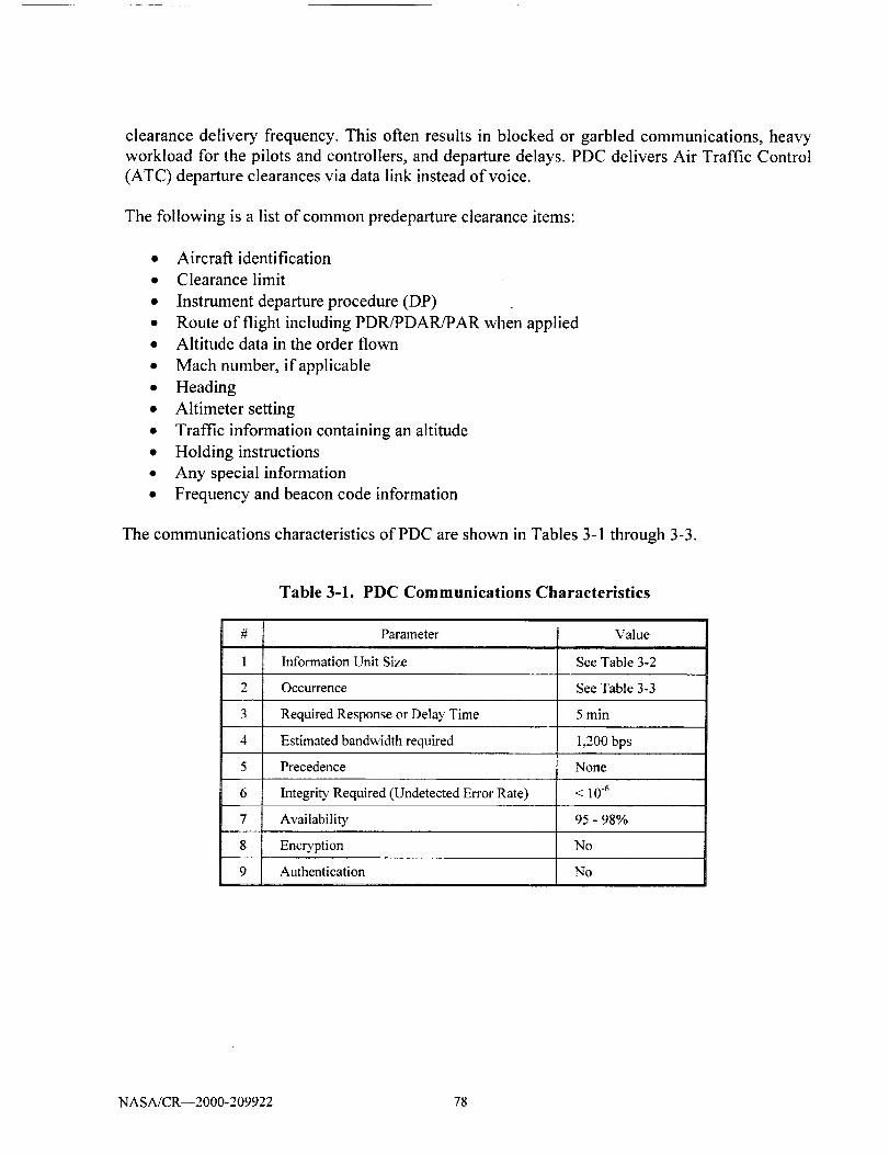
clearance delivery frequency. This often results in blocked or garbled communications, heavy
workload for the pilots and controllers, and departure delays. PDC delivers Air Traffic Control
(ATC) departure clearances via data link instead of voice.
The following is a list of common predeparture clearance items:
• Aircraft identification
• Clearance limit
• Instrument departure procedure (DP)
• Route of flight including PDR/PDARfPAR when applied• Altitude data in the order flown
• Mach number, if applicable
• Heading
• Altimeter setting
• Traffic information containing an altitude
• Holding instructions
• Any special information
• Frequency and beacon code information
The communications characteristics of PDC are shown in Tables 3-1 through 3-3.
#
1
2
3
4
5
6
7
8
9
Table 3-1. PDC Communications Characteristics
Parameter Value
Information Unit Size See Table 3-2
Occurrence See Table 3-3
Required Response or Delay Time 5 min
Estimated bandwidth required 1,200 bps
Precedence None
Integrity Required (Undetected Error Rate) < 10 .6
Availability 95 - 98%
Encryption No
Authentication No
NASA/CR--2000-209922 78
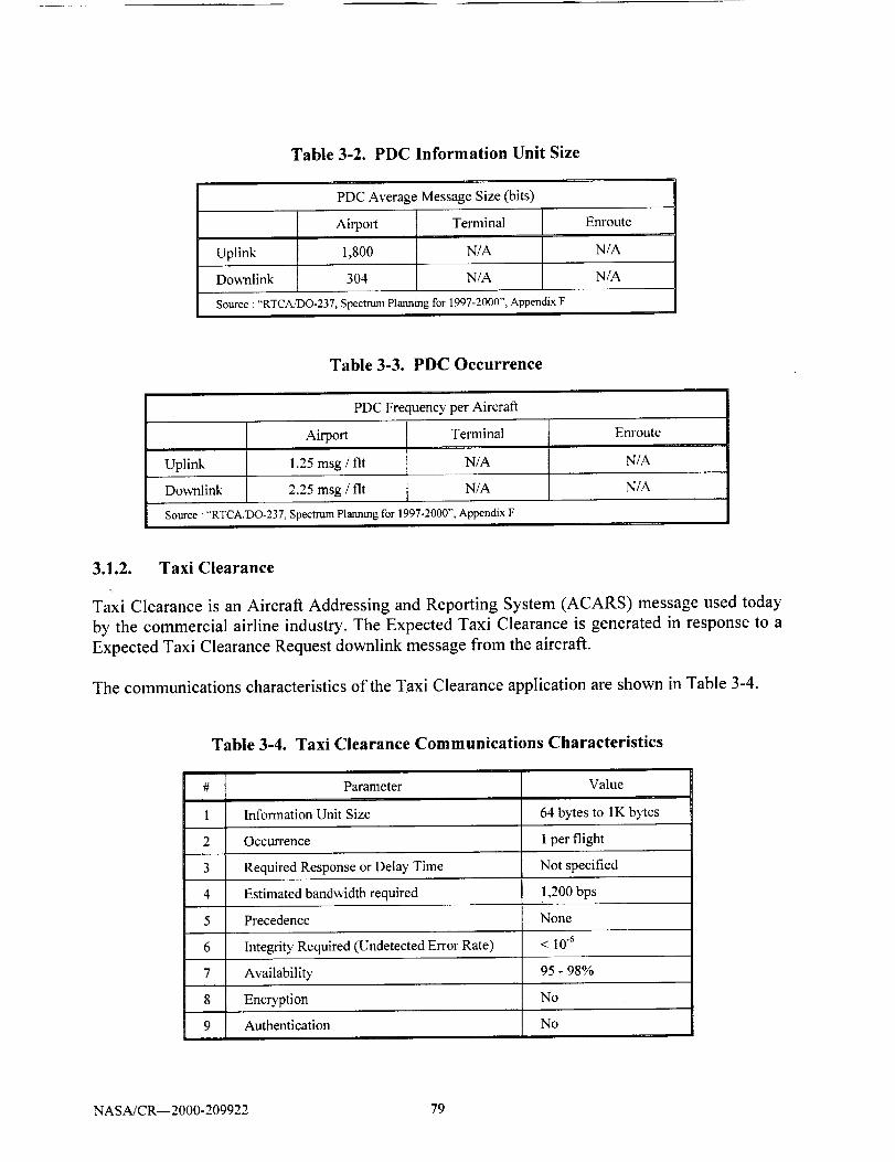
Table 3-2. PDC Information Unit Size
PDC Average Message Size (bits)
Airport Terminal
Uplink 1,800 N/A
Downlink 304 N/A
Source :"RTCAJDO-237, Spectrwn Planning for 1997-2000", Appendix F
Enroute
N/A
N/A
Table 3-3. PDC Occurrence
PDC Frequency per Aircraft
Terminal t Enroute
m
Airport
Uplink 1.25 msg / fit N/A N/A
Downlink 2.25 msg / fit N/A N/A
Source : "RTCA/DO-237, SpectrumPlanning for 1997-2000", Appendix F
3.1.2. Taxi Clearance
Taxi Clearance is an Aircraft Addressing and Reporting System (ACARS) message used today
by the commercial airline industry. The Expected Taxi Clearance is generated in response to a
Expected Taxi Clearance Request downlink message from the aircraft.
The communications characteristics of the Taxi Clearance application are shown in Table 3-4.
Table 3-4. Taxi Clearance Communications Characteristics
Parameter Value
Information Unit Size 64 bytes to 1K bytes
Occurrence 1 per flight
Required Response or Delay Time Not specified
Estimated bandwidth required 1,200 bps
Precedence None
Integrity Required (Undetected Error Rate) < 10 -6
Availability 95 - 98%
Encryption No
Authentication No
NASA/CR--2000-209922 79

3.1.3. Context Management (CM)
Reference: Comprehensive A TN Manual (CAMEL) Part Ill, Guidance Material
CM is the application that initiates and maintains the data link connection between an aircraft
and a ground system. The functions which the CM application provides are:
,, Logon Function: Supports the exchange of application information between the aircraft
and the ground system.
• Update Function: Allows a ground system to modify application data held by an aircraft.
• Contact Function: Allows a ground system to direct an aircraft to logon to another ground
system.
• Forward Function: Allows a ground system to forward aircraft application information to
another ground system.
• Registration Function: Allows an aircraft and ground system to make application
information available to other applications or communications systems in the aircraft or
ground system.
The communications characteristics of CM are shown in Table 3-5.
Table 3-5. CM Communications Characteristics
#
1
2
3
4
5
6
7
8
9
Parameter Value
Information Unit Size About 120 bytes
Occurrence 1 per flight uplink, 1 per flight downlink
Required Response or Delay Time 4 minutes
Estimated bandwidth required 1,200 bps
Precedence Multi-level
Integri_ rRequired (Undetected Error Rate) < 10.6
Availability 99.99%
Encryption No (Future desired)
Authentication No (Future desired)
NASA/CR--2000-209922 80

3.1.4. Controller Pilot Data Link Communication (CPDLC)
Controller Pilot Data Link Communication (CPDLC) is a means of communication between a
controller and a pilot using data link for ATC communication. The CPDLC application provides
air-ground data communication for ATC service. This includes a set of clearance/information/
request message elements which correspond to the voice phraseology employed by Air Traffic
Control procedures. The controller is provided with the capability to issue level assignments,
crossing constraints, lateral deviations, route changes and clearances, speed assignments, radio
frequency assignments, and various requests for information. The pilot is provided with the
capability to respond to messages, to request clearances and information, to report information,
and to declare/rescind an emergency. The pilot is, in addition, provided with the capability to
request conditional clearances (downstream) and information from a downstream Air Traffic
Service Unit (ATSU). A "free text" capability is also provided to exchange information not
conforming to defined fomaats. The uplink (controller) and downlink (pilot) messages are shown
in Appendix B. An auxiliary capability is provided to allow a ground system to use data link to
forward a CPDLC message to another ground system.
Controllers and pilots will use CPDLC in conjunction with the existing voice communications. It
is expected to be used for routine or frequent types of transactions. Although initial
implementation is intended to conform to existing procedures, it is anticipated that future
evolution of the system and procedures will result in the greater automation of functions for both
aircraft and ground systems.
Sending a message by CPDLC consists of selecting the recipient, selecting the appropriate
message from a displayed menu or by other means which allow fast and efficient message
selection, and executing the transmission. The received message may be displayed and/or
printed. A message sent by a downstream ATSU will be distinguishable from a CPDLC message
sent by the current ATS unit.
CPDLC may be used to remedy a number of shortcomings of voice communication, such as
voice channel congestion, misunderstanding due to poor voice quality and/or misinterpretation,
and corruption of the signal due to simultaneous transmissions.
Usually the controller's capability is integrated with the flight data processor (FDP) and the
ground-to-ground communications application to provide seamless ATC/ATM capabilities. The
pilot's CPDLC is normally fully integrated with the cockpit, including communications displays
and the Flight Management System (FMS). This integration allows rapid evaluation of ATC
clearances and instructions in relation to aircraft performance capabilities.
Implementation of CPDLC will significantly change the way pilots and controllers communicate.
The communications characteristics of CPDLC are shown in Table 3-6.
NASA/CR--2000-209922 81

Table 3-6. CPDLC Communications Characteristics
Parameter Value
Information Unit Size See Table 3-7
Occurrence See Table 3-8
Required Response or Delay Time 5 seconds
Estimated bandwidth required 1,200 bps
Precedence Multi-level
Integrity Required (Undetected Error Rate) < 10 -6
Availability 99.99%
Encryption No (Future desired)
Authentication No (Future desired)
The average size of a CPDLC message is shown in Table 3-7 and the CPDLC message
frequency in Table 3-8.
Table 3-7. CPDLC Message Size
CPDLC Average Message Size (bits) Per Aircraft
Enroute
Uplink
Ai_o_ Terminal
123 123 I18
Downlink 32 32 34
Source : "RTCA/DO-237, Spectrtun Planning for 1997-2000"', Appendix F
Table 3-8. CPDLC Message Frequency
CPDLC Message Frequency Per Aircraft
Airport Terminal Enroute
Uplink 10msg/flt 9.6 msg/fit 10.2 msg/fit
Do_Ialink 10 msg / fit 13.1 msg / fit 17.4 msg / fit
Solace : ,RTCA/DO-237, Spectrum Planning for 1997-2000", Appendix F
NASA/CR--2000-209922 82

3.1.5. Automatic Dependent Surveillance (ADS)
References: Comprehensive A TN Manual (CAMEL) Part III, Guidance Material
RTCA/DO-23 7, Spectrum Planning for 1997-2000, Appendix F
The Automatic Dependent Surveillance (ADS) application is designed to give automatic reports
to a user. The reports are derived from on-board navigation and position-fixing system. The
reports include aircraft identification, four-dimensional position, and additional data as
appropriate. The ADS reports give positional as well as other information likely to be of use to
the air traffic management function, including air traffic control.
The aircraft provides the information to the user under one of four circumstances:
• Under a contract (known as a demand contract) agreed with the ground system, the
aircraft provides the information immediately and once only.
• Under a contract (known as a periodic contract) agreed with the ground system, the
aircraft provides information on a regular basis.
• Under a contract (known as an event contract) agreed with the ground system, the aircraft
provides information when certain events are detected by the avionics.
Under emergency conditions the aircraft provides information on a regular basis with no
prior agreement with the ground system (known as an emergency contract). An event or
periodic contract must already exist before an emergency contract can be established.
In addition, the ADS application provides a means to forward ADS reports from the ground
system that has contracts with an aircraft to another ground system.
The avionics are capable of supporting contracts with at least four ATC ground systems
simultaneously. Moreover, they are also capable of supporting one demand, one event, and one
periodic contract with each ground system simultaneously.
The communications characteristics of ADS are shown in Table 3-9.
NASA/CR--2000-209922 83

#
1
2
3
4
5
6
7
8
9
Table 3-9. ADS Communications Characteristics
Parameter Value
Information Unit Size 144 bits
Occurrence 1 every 5 minutes or longer
Required Response or Delay Time 1 second
Estimated bandwidth required 1,200 bps
Precedence Multi-level
Integrity Required (Undetected Error Rate) < 106,I
Availability 99.99%
Encryption No
Authentication No
3.1.6. Automatic Dependent Surveillance Broadcast (ADS-B)
Reference." adl faa.gov/index2/doeument_librao,/adsmnent.htm
Air-to-Air Automatic Dependent Surveillance Broadcast (ADS-B). In an ADS-B air-to-air
application, Cockpit Display of Traffic Information (CDTI) is the basic technology which will
enable the pilot to electronically "see and avoid" other aircraft. Each aircraft automatically
broadcasts its position and other information to all other equipped aircraft in the surrounding
area. This information is visually depicted on a CDTI. Independent of ground-based radar, CDTI
will greatly enhance a pilot's situational awareness and lead to safer and more efficient airspace
operations. ADS-B techniques can also enhance traffic collision avoidance systems in the future.
ADS-B may also be used to enhance flight safety and efficiency by broadcasting wind vector andweather information.
Air-to-Ground ADS-B. ADS-B will provide surveillance data to controllers or aircraft operations
facilities on the ground. An aircraft in flight broadcasts its position, altitude, identification, and
other pertinent information to ground stations that relay this data to air traffic control and/or
airlines operations centers. This information is used to effectively establish surveillance in
remote locations or extend or replace current surveillance capabilities. Air-to-Ground ADS-B
can greatly assist controllers and airlines operations centers with airspace management.
Ground-to-Ground ADS-B. ADS-B will provide accurate position and identification of aircraft
and other equipped vehicles for airport surface surveillance. Aircraft and vehicles broadcast
information containing position, speed, heading, identification to ground stations located around
the airport. This information is relayed to air traffic controllers and airport management facilities
personnel. In addition, broadcast information may be received by other aircraft/vehicles to
improve surface situational awareness. Airport surface surveillance, enhanced through the ADS-
NASA/CR--2000-209922 84

B datalink applications, will lead to safer and more efficient airport surface operations in all
weather conditions and at night.
ADS-B is but one component of an end-to-end surveillance system. It is a function on an aircraft,
surface vehicle or obstruction that periodically broadcasts its state vector (horizontal and vertical
position, horizontal and vertical velocity) and other information. ADS-B is automatic because no
external stimulus is required to elicit a transmission. It is dependent because it relies on on-board
navigation sources and on-board broadcast transmission systems to provide surveillance
information to other users and service providers. Any user (either aircraft or ground-based)
within range of this broadcast may choose to receive and process ADS-B surveillance
information. This broadcast information may be used by the recipient's application for improved
situational awareness, conflict avoidance, and airport and airspace management.
The Communications Characteristics of ADS-B are shown in Table 3-10.
Table 3-10. ADS-B Communications Characteristics
Parameter Value
Information Unit Size 144 bits
Occurrence 2 per second (on ground)
1 per second (terminal/approach)
1 ever), 4 seconds (enroute)
Required Response or Delay Time < 0.25 sec
Estimated bandwidth required 10,000 - 18,000 bps
Precedence Multi-level
Integrity Required (Undetected Error Rate) < 10 .6
Availability 99.99%
Encryption No
Authentication No
3.1.7. Waypoint Position Reporting (WPT/POS)
Waypoint Position Reporting (WPT/POS) is used to provide position, altitude, airspeed, and
other flight conditions on a periodic basis. The type of report varies based on aircraft equipage -
voice, ADS, radar, SSR, and CPDLC may all be used to report position data. The airspace
environment and aircraft capability are considered when assigning reporting criteria.
The communications characteristics of WPT/POS are shown in Table 3-11.
NASA/CR--2000-209922 85
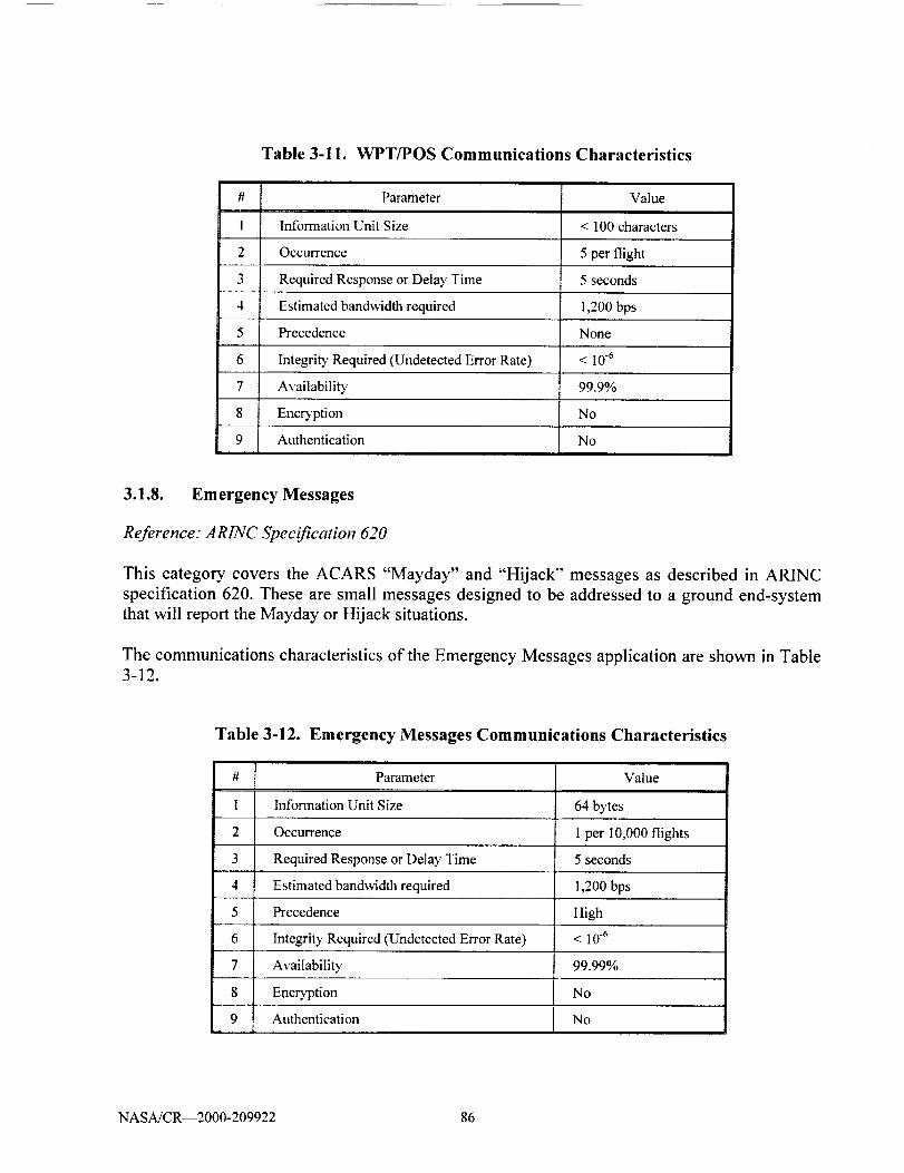
Table 3-11. WPT/POS Communications Characteristics
Parameter Valueii i
Information Unit Size < 100 characters
Occurrence
Required Response or Delay Time
5 per flight
5 seconds
Estimated bandwidth required 1,200 bps
Precedence None
Integrity Required (Undetected Error Rate) < 10-6
Availability 99.9%
Encryption No
Authentication No
3.1.8. Emergency Messages
Reference" AR1NC Specification 620
This category covers the ACARS "Mayday" and "Hijack" messages as described in ARINC
specification 620. These are small messages designed to be addressed to a ground end-system
that will report the Mayday or Hijack situations.
The communications characteristics of the Emergency Messages application are shown in Table
3-12.
Table 3-12. Emergency Messages Communications Characteristics
Parameter Value
Information Unit Size 64 bytes
Occurrence 1 per I0,000 flights
5 secondsRequired Response or Delay Time
Estimated bandwidth required
Precedence
Integrity Required (Undetected Error Rate)
1,200 bps
High
< 10-6
Availability 99.99%
Encryption No
Authentication No
NASA/CR--2000-209922 86

3.1.9. Future Air Navigation System (FANS)
The Future Air Navigation System (FANS) is part of an international movement to reduce or
eliminate the need for aircraft to use airways, moving instead to a Free Flight concept. FANS
consists of three parts: communications, navigation, and surveillance (CNS). Communications
are usually provided via satellite but can also be accomplished via a data link. The navigation
portion of the system is provided by the Flight Management Computer (FMC) which uses GPS,inertial, air data, and other navigation radios, if available. Surveillance is done at an Air Traffic
Management (ATM) center where the aircraft are tracked. The benefit to this system is thataircraft can be tracked at all times even where there is no radar. It also allows reduced separation
between aircraft. Today airplanes have to be separated by extreme amounts (about 60 miles)
when flying oceanic to avoid mid-air collisions due to navigation errors. With GPS to provide
more accurate position information and satellite communications to report positions, separation
can be reduced because the locations of the aircraft are known with great accuracy.
Boeing has certified the FANS-1 system on the 747-400 airplane. Airbus is working on a similar
system called FANS-A.
The communications characteristics of the FANS application are shown in Table 3-13.
Table 3-13. FANS Communications Characteristics
# Parameter
1 Information Unit Size
2 Occurrence
Value
64 to 4,096 bytes
1 to 200 per flight
Required Response or Delay Time 5 seconds
Estimated bandwidth required 1,200 - 10,000 bps
Precedence Multi-level
Integrity Required (Undetected Error Rate) < 10 .6
Availability 99.99%
Encryption No
Authentication No
3.1.10. Oceanic Clearance
Aircraft transiting oceanic airspace are required to have a clearance prior to departure. After the
flight plan is filed by the AOC, it is transmitted to the local ATSU. On receipt of the flight plan,
the ATSU host computer detects that the flight plan is an oceanic request, and forwards it to the
appropriate downstream ATSUs, and to the oceanic ATSU having responsibility for the aircraft"s
oceanic entry point.
NASA/CR--2000-209922 87

If the oceanic airspace has an organized track system program (North Atlantic and Pacific), a
time, fuel efficient set of routes is generated to accommodate the expected combined air traffic
density. Entry points called 'gateways', altitudes, and any restrictions are published for the users.
At the AOC, as part of the flight plan filing process, the aircraft may request multiple oceanic
entry points that closest match the intended route of flight and provide the best operating
trajectory. This request is transmitted to the oceanic ATSU, compiled with other, competing
requests, and an gateway, entry time, and track are assigned.
When the aircraft is preparing for departure, the pilot requests the route clearance. When the
necessary inter-ATSU coordination is completed, the Oceanic clearance approves the departure
time (to ensure the aircraft can comply with the gateway entry time). The ATS control tower at
the departure airport issues the oceanic clearance to the aircraft. The Oceanic Clearance is an
uplink message prepared by the ATC facility and sent to the ground DSP who then forwards the
message to the aircraft end system that issued the initial request.
A typical oceanic clearance message contains standard aircraft data, such as aircraft flightidentification, type aircraft, its communications capabilities, and other aeronautical data. The
route portion of the clearance contains departure instructions, a route of flight to the oceanic
gateway, the route of flight along the published track (or a random route or mapped route), entry
point(s) to adjacent oceanic airspace, exit routing and the exit gateway from oceanic airspace,
arrival instructions, and the altitude(s) for each segment of the flight. A transponder code is also
assigned.
The communications characteristics of the Oceanic Clearance application are shown in Table3-14.
Table 3-14. Oceanic Clearance Communications Characteristics
#
1
2
3
4
5
6
7
8
9
Parameter Value
Information Unit Size 500 bytes
Occurrence 2 per flight. (1 at takeoff, 1 at landing)
Required Response or Delay Time Not specified
Estimated bandwidth required 1,200 bps
Precedence Multi-level
IntegritT Required (Undetected Error Rate) < 10.6
Availability 95 - 98%
EncD'ption No
Authentication No
NASA/CR--2000-209922 88

3.1.11. Future Free Flight
Free Flight is an innovative concept designed to enhance the safety and efficiency of the
National Airspace System (NAS). The concept moves the NAS from a centralized command and
control system between pilots and air traffic controllers to a distributed system that allows pilots,
whenever practical, to choose their own route and file a flight plan that follows the most efficient
and economical route.
Free Flight calls for limiting pilot flexibility in certain situations, such as, to ensure separation at
high-traffic airports and in congested airspace, to prevent unauthorized entry into special use
airspace, and for any safety reason.
Central to the Free Flight concept is the principle of maintaining safe airborne separation. This
principle is based on two airspace zones, protected and alert. The size of each is based on the
aircraft's speed, performance characteristics, and communications, navigation, and surveillance
equipment. The protected zone (the one closest to the aircraft) can never meet the protected zone
of another aircraft. The alert zone extends well beyond the protected zone, and aircraft can
maneuver freely until alert zones touch. If alert zones do touch, a controller may provide one or
both pilots with course corrections or restrictions to ensure separation. Eventually, most
commands will be sent via data link, an integrated network of air, ground, and airborne
communications systems. Additionally, onboard computers and Global Positioning System
satellites will allow pilots, with the concurrence of controllers, to use airborne traffic displays to
choose solutions.
The functions of "Free Flight" include:
• Global Positioning System-based en route navigation, and Category I/II/III approaches
and landings; i.e., WAAS/LAAS.
• Automatic Dependent Surveillance-Broadcast (ADS-B)
• Controller Pilot Data Link Communication (CPDLC)
• Flight Information Services, including FAA-provided weather information for the cockpit
• Cockpit display of terrain and/or traffic information for pilot situational awareness
• Decision Support Systems, including improved oceanic conflict probe
The communications characteristics of the Free Flight application are shown in Table 3-15.
NASA/CR--2000-209922 89
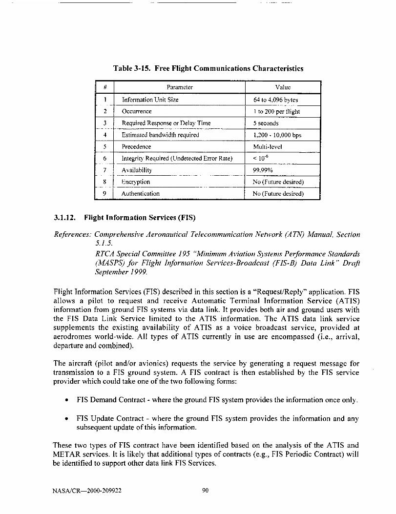
#
1
2
3
4
5
6
7
8
9
Table 3-15. Free Flight Communications Characteristics
Parameter Value
Information Unit Size 64 to 4,096 bytes
Occurrence 1 to 200 per flight
Required Response or Delay Time 5 seconds
Estimated bandwidth required 1,200 - 10,000 bps
Precedence Multi-level
Integrity Required (Undetected Error Rate) < 10 .6
AvailabilitT 99.99%
Enc_'ption No (Future desired)
Authentication No (Future desired)
3.1.12. Flight Information Services (FIS)
References: Comprehensive Aeronautical Telecommunication Network (14777) Manual, Section5.1.5.
RTCA Special Committee 195 "Minimum Aviation Systems Performance Standards
(MASPS) for Flight h_formation Services-Broadcast (FIS-B) Data Link" Draft
September 1999.
Flight Information Services (FIS) described in this section is a "Request/Reply" application. FIS
allows a pilot to request and receive Automatic Terminal Information Service (ATIS)
information from ground FIS systems via data link. It provides both air and ground users with
the FIS Data Link Service limited to the ATIS information. The ATIS data link service
supplements the existing availability of ATIS as a voice broadcast service, provided at
aerodromes world-wide. All types of ATIS currently in use are encompassed (i.e., arrival,
departure and combined).
The aircraft (pilot and/or avionics) requests the service by generating a request message for
transmission to a FIS ground system. A FIS contract is then established by the FIS service
provider which could take one of the two following forms:
• FIS Demand Contract - where the ground FIS system provides the information once only.
• FIS Update Contract - where the ground FIS system provides the information and any
subsequent update of this information.
These two types of FIS contract have been identified based on the analysis of the ATIS and
METAR services. It is likely that additional types of contracts (e.g., FIS Periodic Contract) will
be identified to support other data link FIS Services.
NASA/CR--2000-209922 90

FIS is a system that can support many products. The following lists some of the planned
ATC/ATS application planned for FIS. The list is divided into text based products and graphical
based products.
Textual FIS Products
• METAR and SPECI
• TAF and Amended TAF
• SIGMET
• Convective SIGMET
• AIRMET
• PIREP
• AWW
• Winds and Temperatures Aloft
Graphical FIS Products
• National/Regional NEXRAD
• Radar echo tops graphics
• Storm tops and velocity
• Lightning strike
• Point phenomena
• Surface conditions/winter precipitation graphic
• Surface weather systems
• National METAR Graphic
• CATMET format
• Regional METAR Graphic
• AIRMET, SIGMET
• Bitmap encoding• Gridded Weather Forecast Products
The communications characteristics of FIS are shown in Table 3-16.
NASA/CR--2000-209922 91
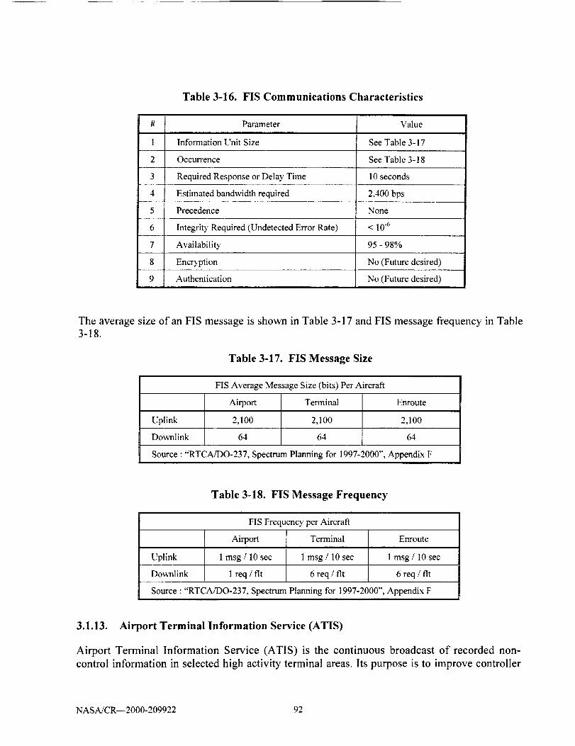
2
3
4
5
6
7
8
9
Table 3-16. FIS Communications Characteristics
Parameter Value
Information Unit Size See Table 3-17
Occurrence See Table 3-18
Required Response or Delay Time 10 seconds
Estimated bandwidth required 2,400 bps
Precedence None
Integrit T Required (Undetected Error Rate) < 10"6
Availabili_' 95 - 98%
Encryption No (Future desired)
Authentication No (Future desired)
The average size of an FIS message is shown in Table 3-17 and FIS message frequency in Table
3-18.
Table 3-17. FIS Message Size
FIS Average Message Size (bits) Per Aircraft
Airport Terminal Enroute
Uplink 2,100 2,100 2,100
Downlink 64 64 64
Source : "RTCA/DO-237, Spectrum Planning for 1997-2000", Appendix F
Table 3-18. FIS Message Frequency
FIS Frequency per Aircraft
Airport Terminal Enroute
Uplink 1 msg / 10 sec 1 msg / 10 sec 1 msg / 10 sec
Downlink 1 req / fit 6 req / fit 6 req / fit
Source : "RTCA/DO-237, Spectrum Planning for 1997-2000", Appendix F
3.1.13. Airport Terminal Information Service (ATIS)
Airport Terminal Information Service (ATIS) is the continuous broadcast of recorded non-
control information in selected high activity terminal areas. Its purpose is to improve controller
NASA/CR--2000-209922 92

effectiveness and to relieve frequency congestion by automating the repetitive transmission of
essential but routine information. The information is continuously broadcast over a discrete VHF
radio frequency or the voice portion of a local NAVAID. ATIS transmissions on a discrete VHF
radio frequency are engineered to be receivable to a maximum of 60 NM from the ATIS site and
a maximum altitude of 25,000 feet AGL. At most locations, ATIS signals may be received on the
surface of the airport, but local conditions may limit the maximum ATIS reception distance
and/or altitude. Pilots are urged to cooperate in the ATIS program as it relieves frequency
congestion on approach control, ground control, and local control frequencies.
ATIS information includes the time of the latest weather sequence, ceiling, visibility,
obstructions to visibility, temperature, dew point (if available), wind direction (magnetic), and
velocity, altimeter, other pertinent remarks, instrument approach and runway in use. The
ceiling/sky condition, visibility, and obstructions to vision may be omitted from the ATIS
broadcast if the ceiling is above 5,000 feet and the visibility is more than 5 nailes. The departure
runway will only be given if different from the landing runway except at locations having a
separate ATIS for departure. The broadcast may include the appropriate frequency and
instructions for VFR arrivals to make initial contact with approach control. Pilots of aircraft
arriving or departing the terminal area can receive the continuous ATIS broadcast at times when
cockpit duties are least pressing and listen to as many repeats as desired. ATIS broadcast shall be
updated upon the receipt of any official hourly and special weather.
To serve frequency limited aircraft, Flight Service Stations (FSSs) are equipped to transmit on
the omnirange frequency at most en route VORs used as ATIS voice outlets. Such
communication interrupts the ATIS broadcast. Pilots of aircraft equipped to receive on other FSS
frequencies are encouraged to do so in order that these override transmissions may be kept to an
absolute minimum.
The communications characteristics of ATIS are shown in Table 3-19.
Table 3-19. ATIS Communications Characteristics
Parameter Value
Information Unit Size 4,096 bytes
Occurrence Continuous broadcast
Required Response or Delay Time N/A
Estimated bandwidth required 2,400 bps
Precedence None
Integrity Required (Undetected Error Rate) < 10.6
Availability 95 - 98%
NoEncryption
Authentication No
NASA/CR--2000-209922 93
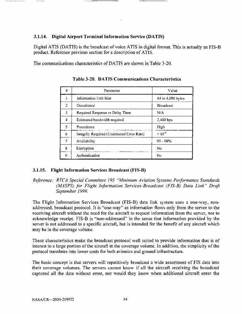
3.1.14. Digital Airport Terminal Information Service (DATIS)
Digital ATIS (DATIS) is the broadcast of voice ATIS in digital format. This is actually an FIS-B
product. Reference previous section for a description of ATIS.
The communications characteristics of DATIS are shown in Table 3-20.
Table 3-20. DATIS Communications Characteristics
#
1
2
3
4
5
6
7
8
9
Parameter Value
Information Unit Size 64 to 4,096 bytes
Occurrence Broadcast
Required Response or Delay Time N/A
Estimated bandwidth required 2,400 bps
Precedence High
Integrity Required (Undetected Error Rate) < 10.6
Availabilit T 95 - 98%
Encryption No
Authentication No
3.1.15. Flight Information Services Broadcast (FIS-B)
Reference." RTCA Special Committee 195 "Minimum Aviation Systems Performance Standards
(MASPS) for Flight Information Services-Broadcast (FIS-B) Data Link" Draft
September 1999.
The Flight Information Services Broadcast (FIS-B) data link system uses a one-way, non-
addressed, broadcast protocol. It is "one-way" as information flows only from the server to the
receiving aircraft without the need for the aircraft to request information from the server, nor to
acknowledge receipt. FIS-B is "non-addressed" in the sense that information provided by the
server is not addressed to a specific aircraft, but is intended for the benefit of any aircraft which
may be in the coverage volume.
These characteristics make the broadcast protocol well suited to provide information that is of
interest to a large portion of the aircraft in the coverage volume. In addition, the simplicity of the
protocol translates into lower costs for both avionics and ground infrastructure.
The basic concept is that servers will repetitively broadcast a wide assortment of FIS data into
their coverage volumes. The servers cannot know if all the aircraft receiving the broadcast
captured all the data without error, nor would they know when additional aircraft enter the
NASA/CR--2000-209922 94

coverage volume and are in need of information. Key to the operational effectiveness of FIS-B
are ensuring the scope of the product list and that the repetition intervals of the products are
suited to the needs of the users in the broadcast coverage volume.
In describing the primary functions of the FIS-B avionics, it is helpful to group them into
continuous and discrete functions. When within the coverage volume, FIS-B avionics would be
expected to monitor the FIS-B frequency (or frequencies) to receive, decode, and store data asthe broadcast server issues them.
The FIS-B avionics would also be expected to automatically manage the contents of an onboard
FIS database in which the received data are stored. Such management functions would include
sorting the data for later retrieval by the pilot or other applications, purging old information that
no longer applies, and passing information directly to the pilot. It is assumed that these functions
would operate more-or-less continuously in the background without any need for direct pilot
management.
The more discrete functions of the FIS-B avionics are those associated with the interaction
between the database and the pilot (through some form of I/O device) or another application.
They are discrete in the sense that they are usually prompted by an action of the pilot (or
application). An example is a pilot-initiated query of the database to obtain the latest surface
observation for an airport of interest. Another example would be the query of the database by an
application to portray weather graphics on a moving map display.
3.1.15.1. Operational Applications
The goal of the FIS-B data link system is to provide weather and other flight advisory
information to pilots in a way that will enhance their awareness of the flight situation and enable
better strategic decision-making. The information provided through FIS-B will be advisory in
nature, and considered non-binding advice and information provided to assist in the safe conduct
of a flight. With this information, pilots will be better able to assess potential hazards as well as
opportunities in the flight environment, and can consequently make decisions that improve
operational safety and efficiency.
At present when the weather deteriorates, voice radio calls from pilots to dispatchers, air traffic
controllers, or flight service station specialists requesting FIS-B kinds of information become
more necessary and more frequent. This clogs voice radio frequencies just when the demand for
the data is the highest. It is envisioned that FIS digital broadcast data will be continuously
received and stored to be readily available as needed or requested by the pilot.
Implementation of an FIS-B data link system is not intended to replace existing voice radio FIS
services. Loss or non-receipt of FIS-B data link services (DLS) would not be considered flight
critical. In the initial implementation, it is anticipated that FIS-B DLS will be used primarily to
supplement or complement established sources of weather and operational information such as
the Flight Service Station network, the Air Traffic Control (ATC) facilities, and/or the
NASA/CR--2000-209922 95

corporate/airlinedispatchers.FIS-B serviceswill assistboth individual pilot and collaborativedecisionmaking(CDM) processes.
3.1.15.2. Air Carriers and Business Operators
Immediate benefits of FIS-B data link to air carriers and business operators include the ability to
make earlier decisions for deviation around weather, and safer, more comfortable flights by
obtaining current weather observations and forecast information in flight. Future growth of FIS
data link applications will support reduction of weather-related diversions, cancellations and
missed connections. The next generation of FIS DLS will help enable the concept of Free Flight,
reducing excessive ground and en route delays, and the requirement to fly circuitous departure
and arrival procedures.
3.1.15.3. General Aviation
General aviation will also benefit from FIS-B data link by being able to make earlier decisions to
divert or curtail the planned flight because of greater awareness of hazardous weather conditions
ahead. In addition, many general aviation pilots are very conservative when planning or
continuing a flight, due to the absence of accurate and sufficient weather information while
airborne. As a result, a significant number of flights are unnecessarily curtailed, cancelled or
terminated early with a corresponding loss of aircraft utility and lost time for affected parties.
Safety suffers as well, such as on an instrument flight, where a pilot may have to leave a busy
ATC frequency to obtain weather information. Information provided by voice alone is often
insufficient to describe a graphical, 3-dimensional picture. FIS-B data link can fill a large void of
information that the pilot enters soon after leaving his ground-based weather-briefing site.
FIS-B is a system that can support many products. The following lists some of the planned
ATC/ATS application planned for FIS. The list is divided into text based products and graphical
based products.
Textual FIS Products
• METAR and SPECI
• TAF and Amended TAF
• SIGMET
• Convective SIGMET
• AIRMET
• PIREP
• AWW
• Winds and Temperatures Aloft
Graphical FIS Products
• National_egional NEXRAD
• Radar echo tops graphics
NASA/CR--2000-209922 96

• Storm tops and velocity
• Lightning strike
• Point phenomena
• Surface conditions/winter precipitation graphic
• Surface weather systems
• National METAR Graphic
• CATMET format
• Regional METAR Graphic
• AIRMET, SIGMET
• Bitmap encoding
• Gridded Weather Forecast Products
The communications characteristics of FIS-B are shown in Table 3-21.
Table 3-21. FIS-B Communications Characteristics
Parameter Value
Information Unit Size 250 bytes
Occurrence Broadcast
Required Response or Delay Time N/A
Estimated bandwidth required 2.400 bps
Precedence None
Integrity Required (Undetected Error Rate) < 10.6
Availability 95 - 98%
Encryption No
Authentication No
3.1.16. Notice to Airmen (NOTAM)
Reference: gopher://venus, hyperk, corn: 210I/
Time-critical aeronautical information which is of either a temporary nature or not sufficiently
known in advance to permit publication on aeronautical charts or in other operational
publications receives immediate dissemination via the National Notice to Airmen (NOTAM)
System. NOTAM information is that aeronautical information that could affect a pilot's decision
to make a flight. It includes such information as airport or primary runway closures, changes in
the status of navigational aids, ILSs, radar service availability, and other information essential to
planned enroute, terminal, or landing operations.
NASA/CR--2000-209922 97

NOTAM information is classified into three categories. These are NOTAM (D) or distant,
NOTAM (L) or local, and Flight Data Center (FDC) NOTAM.
NOTAM (D) information is disseminated for all navigational facilities that are part of the
National Airspace System (NAS), all public use airports, seaplane bases, and heliports
listed in the Airport/Facility Directory (A/FD). The complete file of all NOTAM (D)
information is maintained in a computer data base at the National Communications
Center (NATCOM), located in Kansas City. This category of information is distributed
automatically, appended to the hourly weather reports, via the Service A
telecommunications system. Air traffic facilities, primarily FSSs, with Service A
capability have access to the entire NATCOM database of NOTAMs. These NOTAMs
remain available via Service A for the duration of their validity or until published.
NOTAM (L) information includes such data as taxiway closures, personnel and
equipment near or crossing runways, airport rotating beacon outages and airport lighting
aids that do not affect instrument approach criteria, such as VASI. NOTAM (L)
information is distributed locally only and is not attached to the hourly weather reports. A
separate file of local NOTAMs is maintained at each FSS for facilities in their area only.
NOTAM (L) information for other FSS areas must be specifically requested directly from
the FSS that has responsibility for the airport concerned.
FDC NOTAMs. On those occasions when it becomes necessary to disseminate
information which is regulatory in nature, the National Flight Data Center (NFDC), in
Washington, DC, will issue an FDC NOTAM. FDC NOTAMs contain such things as
amendments to published lAPs and other current aeronautical charts. They are also used
to advertise temporary flight restrictions caused by such things as natural disasters or
large-scale public events that may generate a congestion of air traffic over a site. FDC
NOTAMs are transmitted via Service A only once and are kept on file at the FSS until
published or canceled. FSSs are responsible for maintaining a file of current, unpublished
FDC NOTAMs concerning conditions within 400 miles of their facilities. FDC
information concerning conditions that are more than 400 miles from the FSS, or that is
already published, is given to a pilot only on request.
All new notices entered, excluding FDC NOTAMs, will be published only if the information is
expected to remain in effect for at least 7 days after the effective date of the publication.
The communications characteristics of NOTAM are shown in Table 3-22.
NASA/CR--2000-209922 98
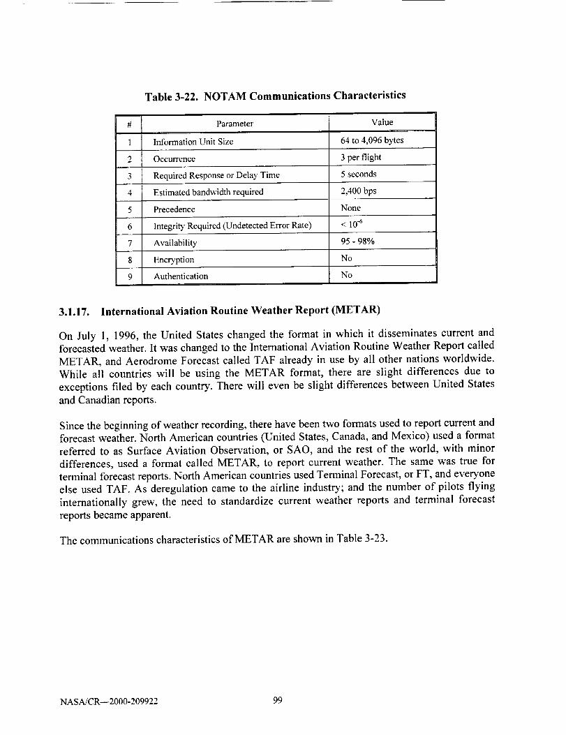
Table 3-22. NOTAM Communications Characteristics
#
1
2
3
4
5
6
7
8
9
Parameter Value
Information Unit Size 64 to 4,096 bytes
Occurrence 3 per flight
Required Response or Delay Time 5 seconds
Estimated bandwidth required 2,400 bps
Precedence None
Integrity Required (Undetected Error Rate) < 10-6
Availability 95 - 98%
Encryption No
Authentication No
3.1.17. International Aviation Routine Weather Report (METAR)
On July 1, 1996, the United States changed the format in which it disseminates current and
forecasted weather. It was changed to the International Aviation Routine Weather Report called
METAR, and Aerodrome Forecast called TAF already in use by all other nations worldwide.
While all countries will be using the METAR format, there are slight differences due to
exceptions flied by each country. There will even be slight differences between United States
and Canadian reports.
Since the beginning of weather recording, there have been two formats used to report current and
forecast weather. North American countries (United States, Canada, and Mexico) used a format
referred to as Surface Aviation Observation, or SAO, and the rest of the world, with minor
differences, used a format called METAR, to report current weather. The same was true for
terminal forecast reports. North American countries used Terminal Forecast, or FT, and everyone
else used TAF. As deregulation came to the airline industry; and the number of pilots flying
internationally grew, the need to standardize current weather reports and terminal forecast
reports became apparent.
The communications characteristics of METAR are shown in Table 3-23.
NASA/CR--2000-209922 99

#
1
2
3
4
5
6
7
8
9
Table 3-23. METAR Communications Characteristics
Parameter Value
Information Unit Size 1,000 b)¢es
Occurrence 20 per flight
5 secondsRequired Response or Delay Time
Estimated bandwidth required
Precedence
1,200 bps
None
Integrity Required (Undetected Error Rate) < 10 .6
Availability 95 - 98%
Encryption No
Authentication No
3.1.18. Terminal Weather Information to Pilots (TWIP)
The Terminal Weather Information for Pilots (TWIP) report is generated in response to a TWIP
Request downlink from the aircratL TWIP is an ACARS message type that is used today by the
commercial airline industry.
If the TWIP Report is destined for the ACARS Management Unit (MU), the ground/ground
TWIP is received by the service provider with the Standard Message Identifier (SMI) of 'TWI'.
The service provider translates the SMI to label AB in the air/ground uplink.
If the TWIP Report uplink message is destined for a peripheral, the appropriate SMI, label (HI)
and Sublabel are used. The Message Format Identifier (MFI) 'AB' is included at the beginning
of the Supplementary Address field.
The communications characteristics of TWIP are shown in Table 3-24.
NASA/CR--2000-209922 1O0

Table 3-24. TWIP Communications Characteristics
Parameter
Information Unit Size
Occurrence
Value
1,000 bytes
2 per flight (1 landing, 1 takeoff)
Required Response or Delay Time 5 seconds
Estimated bandwidth required 1,200 bps
Precedence None
Integrity Required (Undetected Error Rate)
Availability
Encryption
Authentication
< 10 .6
95 - 98%
No
No
3.1.19. Wide Area Augmentation System (WAAS)
Reference." gps,faa.gov/Programs/WAAS/waas.htm
The basic GPS service fails to meet the accuracy (the difference between the measured position
at any given time to the actual or true position), availability (the ability of a system to be used for
navigation whenever it is needed by the users, and its ability to provide that service throughout a
flight operation), and integrity (the ability of a system to provide timely warnings to users or toshut itself down when it should not be used for navigation) requirements critical to safety of
flight.
In order to meet these requirements the FAA is developing the WAAS. This is a safety-critical
navigation system that will provide a quality of positioning information never before available to
the aviation community. It is what the name implies, a geographically expansive augmentation to
the basic GPS service. The WAAS improves the accuracy, integrity, and availability of the basic
GPS signals. This system will allow GPS to be used as a primary means of navigation for
enroute travel and non-precision approaches in the U.S., as well as for Category I approaches to
selected airports throughout the nation. The wide area of coverage for this system includes the
entire United States and some outlying areas such as Canada and Mexico.
The WAAS is based on a network of approximately 25 ground reference stations that covers a
very large service area. Signals from GPS satellites are received by wide area ground reference
stations (WRSs). Each of these precisely surveyed reference stations receive GPS signals and
determine if any errors exist. These WRSs are linked to form the U.S. WAAS network. Each
WRS in the network relays the data to the wide area master station (WMS) where correction
information is computed. The WMS calculates correction algorithms and assesses the integrity of
the system. A correction message is prepared and uplinked to a GEO satellite via a ground uplink
system (GUS). The message is then broadcast on the same frequency as GPS (L 1, 1575.42 MHz)
NASA/CR--2000-209922 101

to receivers onboard aircraft which are flying within the broadcast coverage area of the WAAS.
The communications satellites also act as additional navigation satellites for the aircraft, thus,
providing additional navigation signals for position determination.
The WAAS will improve basic GPS accuracy to approximately 7 meters vertically and
horizontally. It will improve system availability through the use of geostationary communication
satellites (GEOs) carrying navigation payloads and provide important integrity information aboutthe entire GPS constellation.
The communications characteristics of WAAS are shown in Table 3-25.
#
1
2
3
4
5
6
7
8
9
Table 3-25. WAAS Communications Characteristics
Parameter Value
Information Unit Size 64 bytes
Occurrence 1 per second (broadcast)
Required Response or Delay Time N/A
Estimated bandwidth required 1,200 bps
Precedence None
Integrity Required (Undetected Error Rate) < 10 .6
Availability 99.99%
Encryption No
Authentication Yes
3.1.20. Local Area Augmentation System (LAAS)
Reference: gps.faa.gov/Programs/LAAS/laas.htm
The second augmentation to the GPS signal is the Local Area Augmentation System (LAAS).
The LAAS is intended to complement the WAAS and function together to supply users of the
U.S. NAS with seamless satellite based navigation for all phases of flight. In practical terms, this
means that at locations where the WAAS is unable to meet existing navigation and landing
requirements (such as availability), the LAAS will be used to fulfill those requirements. In
addition, the LAAS will meet the more stringent Category II/III requirements that exist at
selected locations throughout the U.S. Beyond Category III, the LAAS will provide the user with
a navigation signal that can be used as an all weather surface navigation capability enabling the
potential use of LAAS as a component of a surface navigation system and an input to surface
surveillance/traffic management systems.
NASA/CR--2000-209922 102
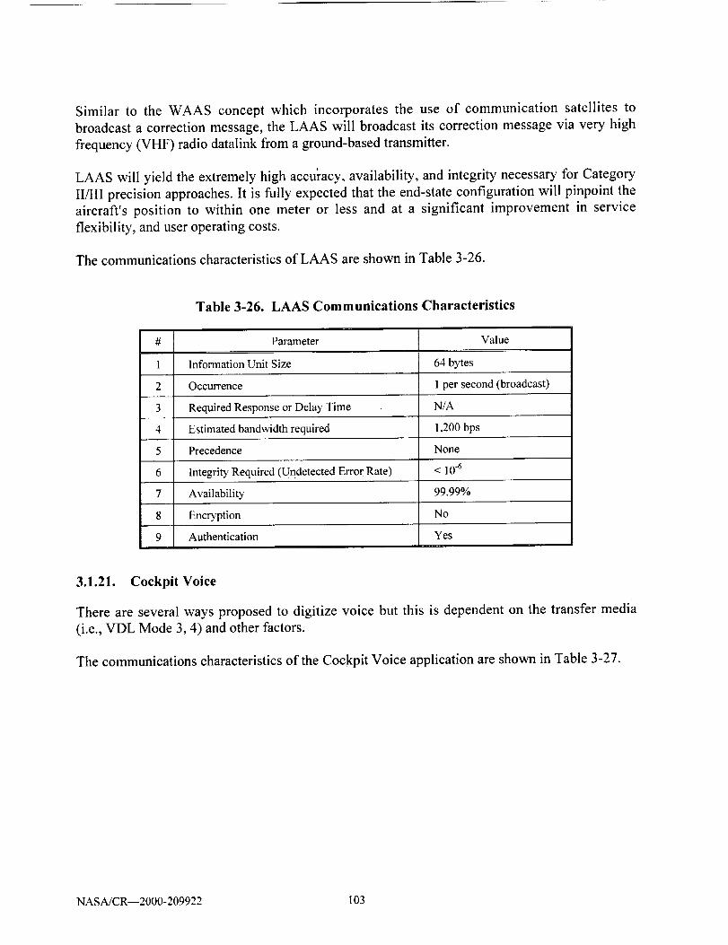
Similar to the WAAS concept which incorporates the use of communication satellites to
broadcast a correction message, the LAAS will broadcast its correction message via very high
frequency (VHF) radio datalink from a ground-based transmitter.
LAAS will yield the extremely high accu]'acy, availability, and integrity necessary for Category
Will precision approaches. It is fully expected that the end-state configuration will pinpoint the
aircraft's position to within one meter or less and at a significant improvement in service
flexibility, and user operating costs.
The communications characteristics of LAAS are shown in Table 3-26.
#
1
2
3
4
5
6
7
8
9
Table 3-26. LAAS Communications Characteristics
Parameter Value
Information Unit Size 64 bytes
Occurrence I per second (broadcast)
Required Response or Delay Time N/A
Estimated bandwidth required 1,200 bps
Precedence None
IntegritT Required (Undetected Error Rate) < 10.6
Availability 99.99%
Encryption No
Authentication Yes
3.1.21. Cockpit Voice
There are several ways proposed to digitize voice but this is dependent on the transfer media
(i.e., VDL Mode 3, 4) and other factors.
The communications characteristics of the Cockpit Voice application are shown in Table 3-27.
NASA/CR--2000-209922 103
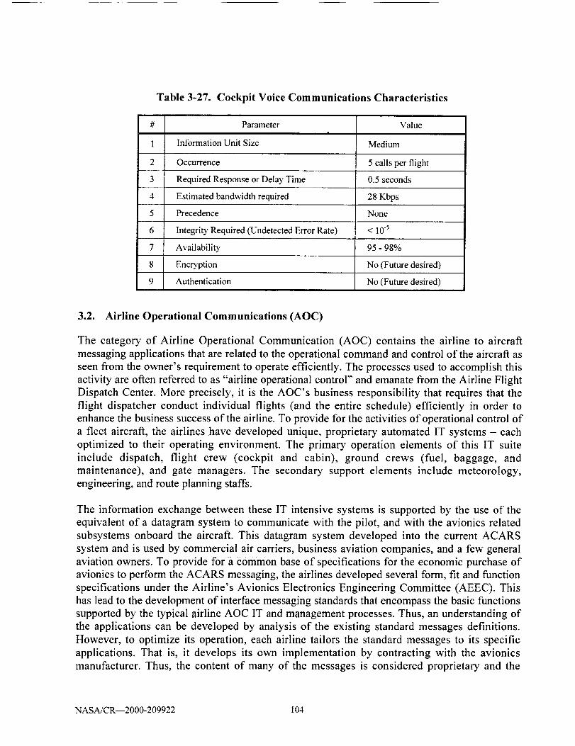
1
2
3
4
5
6
7
8
9
Table 3-27. Cockpit Voice Communications Characteristics
Parameter
Information Unit Size
Value
Medium
Occurrence 5 calls per flight
Required Response or Delay Time 0.5 seconds
Estimated bandwidth required 28 Kbps
Precedence None
Integrity Required (Undetected Error Rate) < 10.5
Availability 95 - 98%
Encryption No (Future desired)
Authentication No (Future desired)
3.2. Airline Operational Communications (AOC)
The category of Airline Operational Communication (AOC) contains the airline to aircraft
messaging applications that are related to the operational command and control of the aircraft as
seen from the owner's requirement to operate efficiently. The processes used to accomplish this
activity are often referred to as "airline operational control" and emanate from the Airline Flight
Dispatch Center. More precisely, it is the AOC's business responsibility that requires that the
flight dispatcher conduct individual flights (and the entire schedule) efficiently in order to
enhance the business success of the airline. To provide for the activities of operational control of
a fleet aircraft, the airlines have developed unique, proprietary automated IT systems - each
optimized to their operating environment. The primary operation elements of this IT suite
include dispatch, flight crew (cockpit and cabin), ground crews (fuel, baggage, and
maintenance), and gate managers. The secondary support elements include meteorology,
engineering, and route planning staffs.
The information exchange between these IT intensive systems is supported by the use of the
equivalent of a datagram system to communicate with the pilot, and with the avionics related
subsystems onboard the aircraft. This datagram system developed into the current ACARS
system and is used by commercial air carriers, business aviation companies, and a few general
aviation owners. To provide for a common base of specifications for the economic purchase of
avionics to perform the ACARS messaging, the airlines developed several form, fit and function
specifications under the Airline's Avionics Electronics Engineering Committee (AEEC). This
has lead to the development of interface messaging standards that encompass the basic functions
supported by the typical airline AOC IT and management processes. Thus, an understanding of
the applications can be developed by analysis of the existing standard messages definitions.
However, to optimize its operation, each airline tailors the standard messages to its specific
applications. That is, it develops its own implementation by contracting with the avionics
manufacturer. Thus, the content of many of the messages is considered proprietary and the
NASA/CR--2000-209922 104
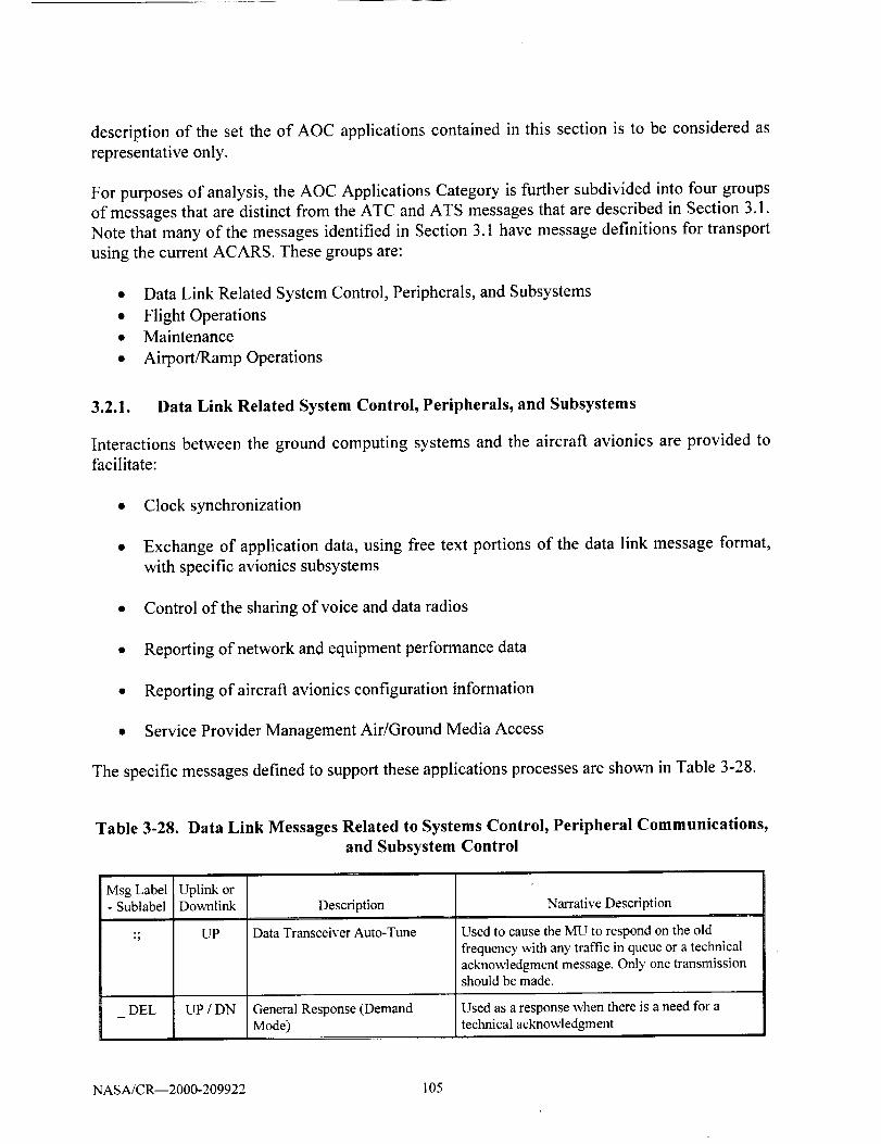
descriptionof the set the of A0C applicationscontainedin this sectionis to be consideredasrepresentativeonly.
For purposesof analysis,the AOC Applications Category is further subdivided into four groups
of messages that are distinct from the ATC and ATS messages that are described in Section 3.1.
Note that many of the messages identified in Section 3.1 have message definitions for transport
using the current ACARS. These groups are:
• Data Link Related System Control, Peripherals, and Subsystems
• Flight Operations
• Maintenance
• Airport/Ramp Operations
3.2.1. Data Link Related System Control, Peripherals, and Subsystems
Interactions between the ground computing systems and the aircraft avionics are provided to
facilitate:
• Clock synchronization
• Exchange of application data, using free text portions of the data link message format,
with specific avionics subsystems
• Control of the sharing of voice and data radios
• Reporting of network and equipment performance data
• Reporting of aircraft avionics configuration information
• Service Provider Management Air/Ground Media Access
The specific messages defined to support these applications processes are shown in Table 3-28.
Table 3-28. Data Link Messages Related to Systems Control, Peripheral Communications,
and Subsystem Control
Msg Label- Sublabel
DEL
Uplink orDovmlink
LIP
UP/DN
Description
Data Transceiver Auto-Tune
General Response (DemandMode)
Narrative Description
Used to cause the MU to respond on the old
frequency with an)' traffic in queue or a technicalacknowledgment message. Only one transmissionshould be made.
Used as a response when there is a need for atechnical acknowledgment
NASA/CR--2000-209922 105

MsgLabel- Sublabel
I III
Uplink orDox_,nlink
52
Description
51 DN Ground GMT Request
51 UP Ground GMT Report
52
54
DN
UP
DN
Ground UTC Request
Ground UTC Report
Voice Contact Request (Ground
Party Address)
Narrative Description
This message is downlinked to request the GMT
time only.
Message is to be transmitted whenever the pilotsignifies his desire for clock update action fromthe ground.
This message is dox_aalinked to request UTC time,
date and an alternative ground UTC report.
Uplink label 52 presents an alternative format fordelivering UTC information. The new format
includes the date and the day of the week as well
as the information already present in label 51.
Aircrew requests for voice contact with a specifiedparbr on the ground. Message permits a complete
area code and telephone number to be downlinkedif desired.
54 UP Voice Go-ahead (or ACARS Uplink provides for free text display of VHFFrequency Uplink) Channel Names.
5P DN Temporary Suspension
Undesignated Cockpit / Cabin
Printer Messages, All Call
UPCO
Communication Service
Message, Printer Status
Annunciation - Error in Printer
C 1 UP Designated Cockpit / CabinPrinter Messages
C2 to C9 UP Designated Cockpit / CabinPrinter Messages
CA DN
Printer BusyDNCB
CC DN
CD DN
CE DN
A message containing Label characters 5P may bedownlinked by the ACARS MU in accordancewith ARINC Specification 618 to indicate the non-
availability of the RF link because the VHF radiowill be temporarily used for voicecommunications.
Used to address different cockpit or cabin printersonboard the aircraft. Label CO is for an
undesignated printer or an "All Call'" printer asdetermined by the airborne system.
Used to address different cockpit or cabin printersonboard the aircraft. Label C1 addresses Printer # 1
Used to address different cockpit or cabin printersonboard the aircraft. Label C2 addresses Printer#2.
A dox_vdink message signifying that the printer is
not installed, not powered or inoperative.
A downlink message signifying that the printer isbusy
Printer in Local or Test Mode A downlink message signifying that the printer istest/local mode.
Printer Out of Paper A do_x_link message signifying that the printer is
out of paper.
Printer Buffer Ovemm A dovmlink message signifying that the printer'sbuffer is overrun.
NASA/CR--2000-209922 106

MsgLabelUplinkor- SublabelDownlink Description NarrativeDescription
CF DN
F3
H1-AI
H1-A2
H1-AD
H1-DF
H1-DF
HI-H1
H1-H2
H1-HD
HI-M1
H1-M1
H1-M2
H1-M2
H1-M3
H1-M3
H1-MD
H1-MD
DN
UP
UP
UP
UP/ DN
UP
UP/DN
UP/DN
UP
UP
UP/DN
UP
UP / DN
UP / DN
UP/DN
UP
UP
Printer Initialized Before
Completion
Printer Status Communication -
Error in Printer
Dedicated Transceiver Advisory
ADS (To left ATSU / ADSU)
ADS (To right ATSU / ADSU)
ADS (To Selected ATSU /ADSU)
Digital Flight Data AcquisitionUnit (Header)
Digital Flight Data AcquisitionUnit (No Header)
HF Data Radio, Left (No Header)
HF Data Radio, Right (No
Header)
HF Data Radio, Selected (No
Header)
Flight Management Computer,
Left (Header)
Flight Management Computer,Left (No Header)
Flight Management Computer,Right (Header)
Flight Management Computer,
Right (No Header)
Flight Management Computer,Center (Header)
Flight Management Computer,Center (No Header)
Flight Management Computer,Selected (Header)
Flight Management Computer,Selected (No Header)
A downlink message signifying that the printerwas initialized (power cycled) during printing
Dovmlink from the airborne subsystem in response
to Voice Go-Ahead (Label 54) uplinks.
Uplinks (With No Header) to Peripherals (Note 1)
Uplinks (With No Header) to Peripherals
Uplinks (With No Header) to Peripherals
Uplinks/Downlinks (with Headers) to Peripherals
Uplinks (With No Header) to Peripherals
Uplinks/Downlinks (With No Header) to
Peripherals
Uplinks/Downlinks (With No Header) toPeripherals
Uplinks (With No Header) to Peripherals
Uplinks (with Headers) to Peripherals
Uplinks/Downlinks (With No Header) to
Peripherals
Uplinks (with Headers) to Peripherals
Uplinks/Dovmlinks (With No Header) to
Peripherals
Uplinks/Dovmlinks (with Headers) to Peripherals
Uplinks/Downlinks (With No Header) toPeripherals
Uplinks (with Headers) to Peripherals
Uplinks (With No Header) to Peripherals
HI- 10 to UP / DN User Defined Messages (No Uplinks/Downlinks (With No Header) to
4- Header) Peripherals
HI-Any UP / DN Optional Auxiliary Terminal Uplinks/Downlinks (with Headers) to Peripherals
Undefined Message (Header)
NASA/CR--2000-209922 107

MsgLabelUplinkor
- Sublabel Downlink Description
HI-None UP / DN Optional AtLxiliary Terminal(Header)
HI-None UP Optional Auxiliar), Terminal (NoHeader)
Narrative Description
Uplinks/Dovv_alinks (with Headers) to Peripherals
Uplinks (With No Header) to Peripherals
H1-PS UP / DN Keyboard/Display Unit Uplinks/Dov_links (With No Header) toPeripherals
H1-S 1 UP / DN SDU, Left (No Header) Uplinks/Downlinks (With No Header) toPeripherals
H1-S2 UP / DN SDU, Right (No Header) Uplinks/Downlinks (no Headers) to PeripheraIs
H1-SD LrP SDU, Selected (No Header) Uplinks (no Headers) to Peripherals
HI-T0 UP Cabin Terminal Message Uplinks (With No Header) to Peripherals
H I-T i to UP / DN Cabin Terminal Messages (No Uplinks/Downlinks (With No Header) toT8 Header) Peripherals
H1-T1 to UP Cabin Terminal Messages ( Uplinks (with Headers) to PeripheralsT8 Header)
FIX DN Undelivered Uplink Report
DN Clock Update AdvisoryQ3
Used by the airborne system after it has
acknowledged all the block(s) of an uplink
message, and is subsequently unsuccessful in itsattempts to deliver that message to an airborne
subsystem. Message indicates that theacknowledged message was not delivered.
The clock update advisory message may, at airline
option, be transmitted automatically whenever theclock is updated by the pilot. It may also be
transmitted whenever the clock is updated
automatically upon receipt of a Ground UTCDelivery Uplink.
Q4 Up Voice Circuit Busy This message is not currently supported.
DNQ5
Q6
Unable to Deliver Uplink
Messages
Voice to Data Channel
Changeover Advisor)'
Intercept/Unable to ProcessQX
DN
DN
When the airbome sub-system cannot accept an
uplinked message it should respond with adownlink containing Label character Q5.
Label Q6 downlink messages will be transmittedin accordance with ARINC Specification 618 toindicate that the VHF radio associated with the
ACARS MU has been returned from Voice to DataService.
When the airborne sub-system wants to Interceptand terminate an uplink transmission (all blocks),
it may respond with a downlink containing Labelcharacters QX. Label QX may also be used to
report that the MU is unable to process an uplink
message.
NASA/CR--2000-209922 108
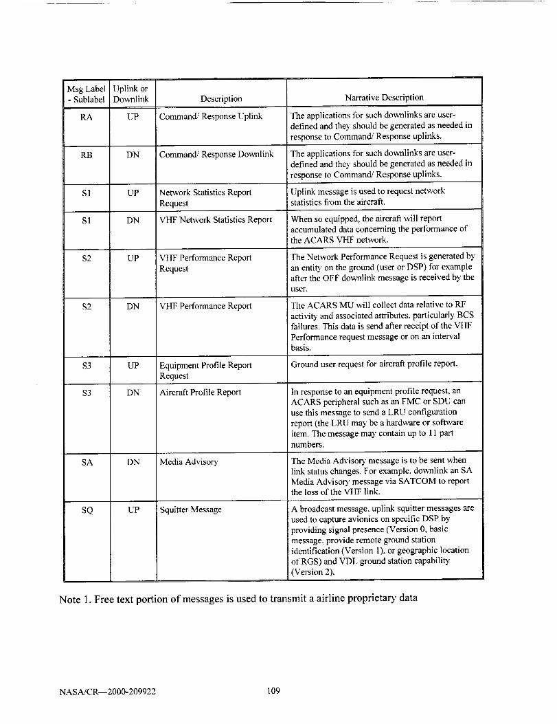
MsgLabelUplinkor- SublabelDov_lalink Description NarrativeDescription
RA UP Command/ResponseUplink
RB
$1
S1
$2
$2
DN
UP
DN
UP
DN
Command/ResponseDownlink
NetworkStatisticsReportRequest
VHYNetwork Statistics Report
VHF Performance Report
Request
VHF Performance Report
The applications for such downlinks are user-defined and they should be generated as needed in
response to Command/Response uplinks.
The applications for such downlinks are user-defined and the), should be generated as needed in
response to Command/Response uplinks.
Uplink message is used to request networkstatistics from the aircraft.
When so equipped, the aircraft will reportaccumulated data concerning the performance ofthe ACARS VHF network.
The Network Performance Request is generated by
an entity on the ground (user or DSP) for exampleafter the OFF downlink message is received by theuser.
The ACARS MU will collect data relative to RF
activity and associated attributes, particularly BCSfailures. This data is send after receipt of the VHF
Performance request message or on an intervalbasis.
$3 UP Equipment Profile Report Ground user request for aircraft profile report.
Request
$3 DN Aircraft Profile Report
SA DN
UPSQ
Media Advisor)"
Squitter Message
In response to an equipment profile request, anACARS peripheral such as an FMC or SDU can
use this message to send a LRU configuration
report (the LRU may be a hardware or softwareitem. The message may contain up to 11 partnumbers.
The Media Advisory message is to be sent when
link status changes. For example, downlink an SAMedia Advisor), message via SATCOM to reportthe loss of the VHF link.
A broadcast message, uplink squitter messages areused to capture avionics on specific DSP by
providing signal presence (Version 0, basic
message, provide remote ground stationidentification (Version 1). or geographic locationof RGS) and VDL ground station capability
(Version 2).
Note 1. Free text portion of messages is used to transmit a airline proprietary data
NASA/CR--2000-209922 109
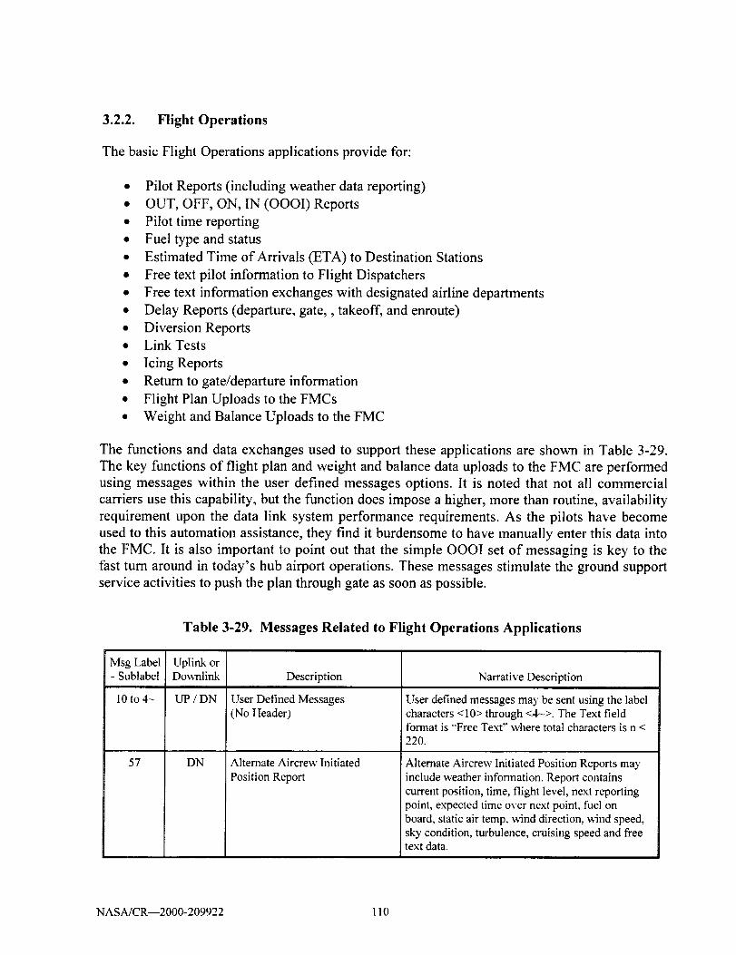
3.2.2. Flight Operations
The basic Flight Operations applications provide for:
• Pilot Reports (including weather data reporting)
• OUT, OFF, ON, IN (OOOI) Reports
• Pilot time reporting
• Fuel type and status
• Estimated Time of Arrivals (ETA) to Destination Stations
• Free text pilot information to Flight Dispatchers
• Free text information exchanges with designated airline departments
• Delay Reports (departure, gate,, takeoff, and enroute)
• Diversion Reports
• Link Tests
• Icing Reports
• Return to gate/departure information
• Flight Plan Uploads to the FMCs
• Weight and Balance Uploads to the FMC
The functions and data exchanges used to support these applications are shown in Table 3-29.
The key functions of flight plan and weight and balance data uploads to the FMC are performed
using messages within the user defined messages options. It is noted that not all commercial
carriers use this capability, but the function does impose a higher, more than routine, availability
requirement upon the data link system performance requirements. As the pilots have become
used to this automation assistance, they find it burdensome to have manually enter this data into
the FMC. It is also important to point out that the simple OOOI set of messaging is key to the
fast turn around in today's hub airport operations. These messages stimulate the ground support
service activities to push the plan through gate as soon as possible.
Table 3-29. Messages Related to Flight Operations Applications
Msg Label- Sublabel
10 to 4-
57
Uplink orDownlink
uP/DN
DN
Description
User Defined Messages(No Header)
Alternate Aircrew Initiated
Position Report
Narrative Description
User defined messages may be sent using the labelcharacters <10> through <4->. The Text fieldformat is "'Free Text" where total characters is n <220.
Alternate Aircrew Initiated Position Reports mayinclude weather information. Report containscurrent position, time, flight level, next reportingpoint, expected time over next point, fuel onboard, static air temp. wind direction, ,Mnd speed,sky condition, turbulence, cruising speed and freetext data.
NASA/CR--2000-209922 110

Msg Label Uplink or- Sublabel Downlink Description Narrative Description
5R DN Aircrew Initiated Position Report Aircrew Initiated Position Reports include weather
information. Report contains current position,
time, flight level, next reporting point, expected
time over next point, fuel on board, static air temp,wind direction, wind speed, sky condition,
turbulence, cruising speed and free text data.
80 to 8-
5Y DN Aircrew Revision to Previous Aircrew Revision to Previous ETA or Diversion
ETA / Diversion Report Reports. Contains new destination, and ETA.
5Z DN Airline Designated Downlink
Aircrew- Addressed Dowaalink
Message
DN
The airline designated downlink is transmitted
when the entered text cannot be appended to a
Departure/Arrival or ETA report, either because itis too long, or because no such reports are awaitingtransmission.
Aircrew-addressed downlinks are routed to
addresses entered by the flight crew. The form of
the address may be predefined, seven-character
teletTpe, three-character station, or four-character.
H3 DN Icing Report Subsystems Used by subsystems onboard theaircraft to give 5-second reports during an icingevent.
M2 DN User Defined Message Airline proprietary format
Q0 DN Link Test This message is downlinked when the pilot pressesthe "TEST" key on his/her control unit followed
by the "'SEND" key.
Q 1 DN Departure/Arrival Report See below. Note free text used to report pilotinformation
Q 1 DN Arrival Report A Arrival report should be transmittedautomatically following the occurrence of the INevent.
Q1 DN Departure Report A Departure report should be transmittedautomatically following the occurrence of the OFFevent.
Q2 DN Estimated Time of Arrival Report Reports estimated time of arrival, destination, andfuel quantity.
DN
DN
Q7 Delay Message
OUT/Fuel Report (IATA AirportCode)
OFF Report (IATA Airport Code)
QA
QB DN
Messages containing information on operationaldelays using free text to report such delays as gateor enroute.
Report transmitted automatically following thedeclaration of the OUT event.
Report format defined to deliver the airportidentification using the 3-character IATA
designator which is transmitted F time, departurestation and free text.
NASA/CR--2000-209922 111
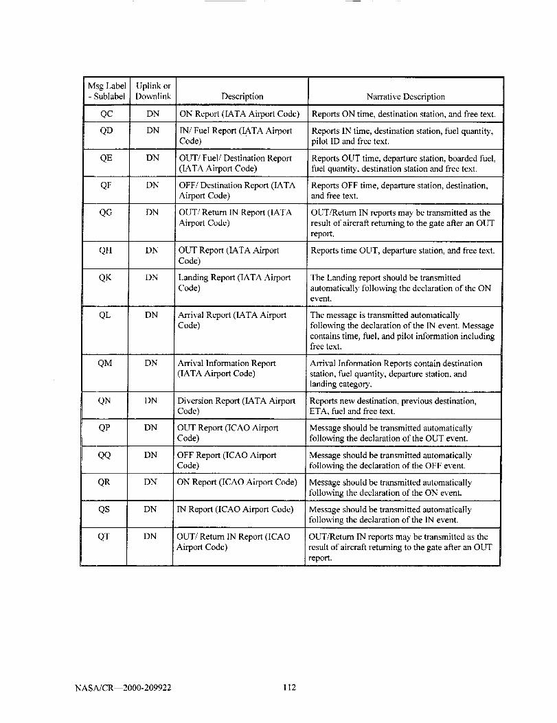
MsgLabel Uplinkor- SublabelDownlink Description
QC DN ONReport(IATAAirportCode)
QD DN IN/FuelReport(I(kTAAirportCode)
Narrative Description
Reports ON time, destination station, and free text.
Reports IN time, destination station, fuel quantity,pilot ID and free text.
QE DN OUT/Fuel/Destination Report Reports OUT time, departure station, boarded fuel,(IATA Airport Code) fuel quantity, destination station and free text.
QF DN
QG
QH
QK
QL
DN
DN
DN
DN
DN
DN
DN
QM
OFF/Destination Report (IATAAirport Code)
OUT/Return IN Report (IATA
Airport Code)
OUT Report (IATA AirportCode)
Landing Report (IATA AirportCode)
Arrival Report (IATA AirportCode)
Arrival Information Report(IATA Airport Code)
Diversion Report (IATA AirportCode)
OUT Report (ICAO AirportCode)
QN
QP
Reports OFF time, departure station, destination,and free text.
OUT/Return IN reports may be transmitted as theresult of aircraft returning to the gate after an OUT
report.
Reports time OUT, departure station, and free text.
The Landing report should be transmittedautomatically following the declaration of the ONevent.
The message is transmitted automaticallyfollowing the declaration of the IN event. Message
contains time, fuel, and pilot information includingfree text.
Arrival Information Reports contain destinationstation, fuel quantity, departure station, and
landing category.
Reports new destination, previous destination,ETA, fuel and free text.
Message should be transmitted automaticallyfollow4ng the declaration of the OUT event.
QQ DN OFF Report (ICAO Airport Message should be transmitted automaticallyCode) tbllowing the declaration of the OFF event.
QR DN ON Report (ICAO Airport Code) Message should be transmitted automaticallyfollowing the declaration of the ON event.
QS DN IN Report (ICA0 Airport Code)
QT OUT/Return IN Report (ICAOAirport Code)
DN
Message should be transmitted automaticallyfollowing the declaration of the IN event.
OUT/Return IN reports may be transmitted as theresult of aircraft returning to the gate after an OUT
report.
NASA/CR--2000-209922 112
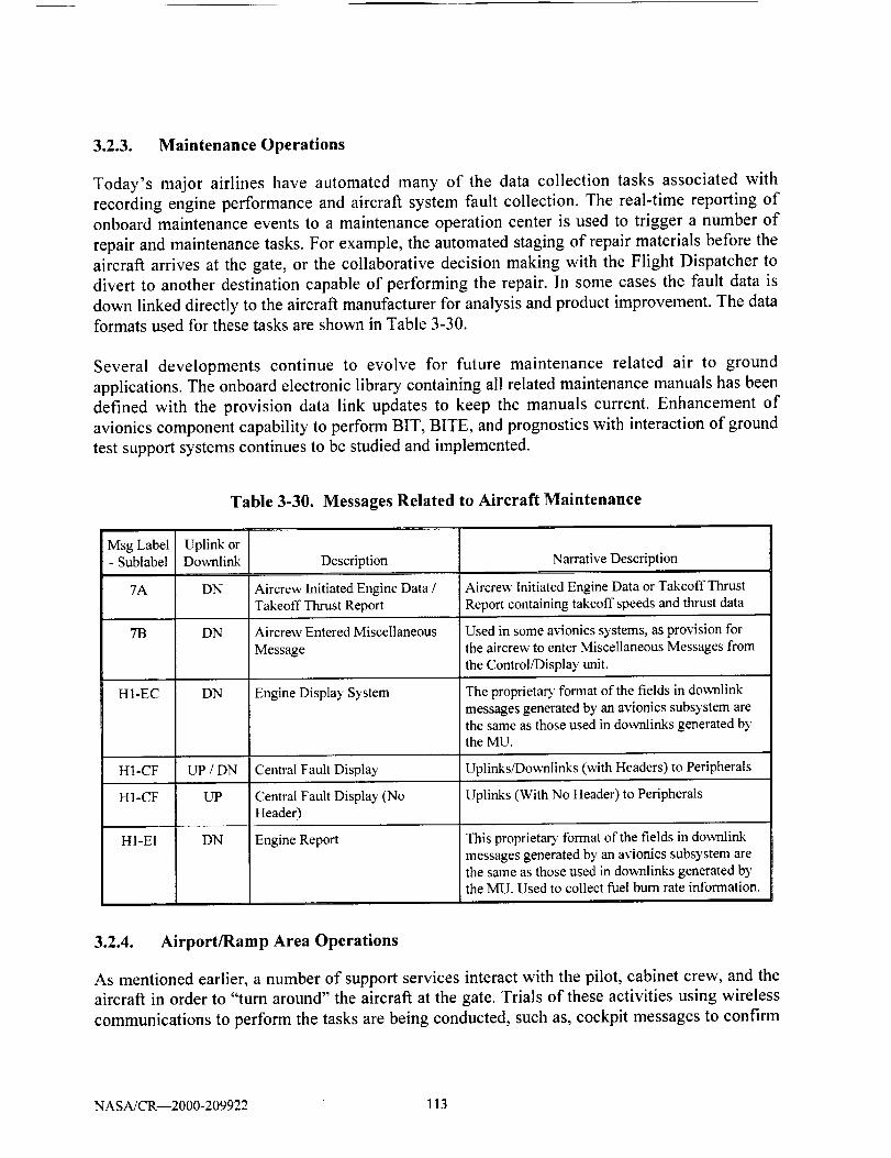
3.2.3. Maintenance Operations
Today's major airlines have automated many of the data collection tasks associated with
recording engine performance and aircraft system fault collection. The real-time reporting of
onboard maintenance events to a maintenance operation center is used to trigger a number of
repair and maintenance tasks. For example, the automated staging of repair materials before the
aircraft arrives at the gate, or the collaborative decision making with the Flight Dispatcher to
divert to another destination capable of performing the repair. In some cases the fault data is
down linked directly to the aircraft manufacturer for analysis and product improvement. The data
formats used for these tasks are shown in Table 3-30.
Several developments continue to evolve for future maintenance related air to ground
applications. The onboard electronic library containing all related maintenance manuals has been
defined with the provision data link updates to keep the manuals current. Enhancement of
avionics component capability to perform BIT, BITE, and prognostics with interaction of ground
test support systems continues to be studied and implemented.
Table 3-30. Messages Related to Aircraft Maintenance
Msg Label- Sublabel
7A
7B
H1-EC
Uplink orDownlink
DN
DN
DN
Description
Aircrew Initiated Engine Data /
Takeoff Thrust Report
Aircrew Entered Miscellaneous
Message
Engine Display System
Narrative Description
Aircrew Initiated Engine Data or Takeoff Thrust
Report containing takeoff speeds and thrust data
Used in some avionics systems, as provision for
the aircrew to enter Miscellaneous Messages from
the Control/Display unit.
The proprietary format of the fields in downlink
messages generated by an avionics subsystem arethe same as those used in downlinks generated bythe MU.
H1-CF UP / DN Central Fault Display Uplinks/Downlinks (with Headers) to Peripherals
H1-CF UP Central Fault Display (No Uplinks (With No Header) to PeripheralsHeader)
H1-EI DN Engine Report This proprietarT format of the fields in downlinkmessages generated by an avionics subsystem arethe same as those used in downlinks generated bythe MU. Used to collect fuel burn rate information.
3.2.4. Airport/Ramp Area Operations
As mentioned earlier, a number of support services interact with the pilot, cabinet crew, and the
aircraft in order to "turn around" the aircraft at the gate. Trials of these activities using wireless
communications to perform the tasks are being conducted, such as, cockpit messages to confirm
NASA/CR--2000-209922 113

completion of deicing applications. It is expected that the communication requirements imposed
by these applications will be similar to those performed today.
3.2.5. Cockpit Voice Operations (Company)
Many of the operations and interactions with the Flight Dispatcher occur using voice RF based
communications. Airline companies maintain their own frequencies or use a shared system. This
communications also backs up the data link and is required by the FAA FAR, The voice
messaging uses standard radio protocols to complete the information transfer. These channels are
extremely important in times of emergency (maintenance events) and in weather related
diversions of aircraft. Continued provision of voice services and the recognition that current
information exchanges performed in voice may be transferred to new data link messages is to be
remembered in any future communications analysis
3.2.6. AOC Communications Requirement Parameters
The applications covered under the category of AOC are performed today using a Data Link
Service Provider. The communications are performed using an interactive network approach
with the exception of the squitter data links that use a broadcast technique to capture the aircraft
to a specific service provider.
The communications requirements of the AOC applications are all the same for the parameters of
interest to this analysis. The communications characteristics of AOC are shown in Table 3-31.
Table 3-31. AOC Communications Characteristics
5
6
7
8
9
Parameter Value
Information Unit Size Messages < 256 bytes
Multi-block messages < 3,000 bytes
Occurrence 14 - 16 messages per flight segment
Required Response or Delay Time < 1 rain delivery
Reject messages > 5 min old
Estimated bandwidth required VHF system - 1,200 bps
Satellite system - approx. 10,000 bps
Precedence None
Integrity Required (Undetected Error Rate) 10 .6 to 10"7
Availability 95 - 98%
Encryption No
Authentication No
NASAJCR--2000-209922 114
Using the above parameters is sufficient, as in some cases there is a wide difference in the
specific values due to service providers and due to the differing implementations of proprietary
airline AOC systems. However, these values do represent the current quality considered
satisfactory based on economics and performance.
3.3. Airline Administrative Communication
The category of Airline Administrative Communication (AAC) pertains to the airline to aircraft
messaging applications that are related to the routine administration of what can be defined as
cabinet crew operations. The line between AOC and AAC is not drawn by clear definitions. It
has been retained within this application collection and review task in order to capture a set of
applications that continue to be developed for passenger services. The additional use of
communications by the cabin crew are seen as a means of providing better service, such as
custom clearing activity, handling delays and connections information, as well the misroute of
baggage information.
Presently, there are no common standards for these applications and each airline makes use of an
implementation by using user defined messages within the ACARS interface formats. Thus, the
content of the many of the messages is considered proprietary and the description of the set the
of AAC applications contained in this section is to be considered as representative only.
There are presently only a few data link messages that are within this category and may by FCC
licensing be transmitted on the current air-to ground data link. The following list broadly defines
the applications:
• Airlines Gate Connections
• Medical Assistance Requests
• Crew Schedule and Lodging Information
• Miscellaneous Free Text Crew Information
• Future Applications - Passenger Handling
The content of each item on the list above is self-explanatory, and therefore further descriptive
information is considered unnecessary. It is important to note that, in some cases, these
applications are performed using the airline company voice channels as described under AOC.
The data communications requirements are identical to those stated for AOC. The
communications characteristics of AAC are shown !n Table 3-32.
NASA/CR--2000-209922 115
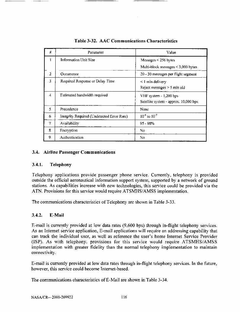
Table 3-32. AAC Communications Characteristics
5
6
7
8
9
Parameter Value
Information Unit Size Messages < 256 bytes
Multi-block messages < 3,000 bytes
Occurrence 20 - 30 messages per flight segment
Required Response or Delay Time < 1 rain deliver)'
Reject messages > 5 rain old
Estimated bandwidth required VHF system - 1,200 bps
Satellite system - approx. I0,000 bps
Precedence None
Integrity Required (Undetected Error Rate) 10.6 to 10-7
Availability 95 - 98%
Encryption No
Authentication No
3.4. Airline Passenger Communications
3.4.1. Telephony
Telephony applications provide passenger phone service. Currently, telephony is provided
outside the official aeronautical information support system, supported by a network of ground
stations. As capabilities increase with new technologies, this service could be provided via the
ATN. Provisions for this service would require ATSMHS/AMSS implementation.
The communications characteristics of Telephony are shown in Table 3-33.
3.4.2. E-Mail
E-mail is currently provided at low data rates (9,600 bps) through in-flight telephony services.
As an Internet service application, E-mail applications will require an addressing capability that
can track the individual user, as well as reference the user's home Internet Service Provider
(ISP). As with telephony, provisions for this service would require ATSMHS/AMSS
implementation with greater fidelity than the normal telephony implementation to maintain
connectivity.
E-mail is currently provided at low data rates through in-flight telephony services. In the future,
however, this service could become Internet-based.
The communications characteristics of E-Mail are shown in Table 3-34.
NASA/CR--2000-209922 116

Table 3-33. Telephony Communications Characteristics
Parameter Value
Information Unit Size Medium
Occurrence Less than 2% of the passengers per flight
Required Response or Delay Time N/A
Estimated bandwidth required > 9,600 bps
Precedence None
Integrity Required (Undetected Error Rate) < 10 .5
Availability 99.9%
Encryption No
Authentication No
Table 3-34. E-Mail Communications Characteristics
Parameter Value
Information Unit Size Small
Occurrence < 10% of passenger per flight
Required Response or Delay Time NA
Estimated bandwidth required > 9,600 bps
Precedence None
Integrity Required (Undetected Error < 10.__Rate)
Availability 99.9%
Encryption No
Authentication No
3.4.3. lnternet Services
As more and more business is conducted on-line, there will be an increasing demand to provide
Intemet services to passengers. As with telephony, provisions for this service would require
ATSMHS/AMSS implementation with greater fidelity than the normal telephony
implementation to maintain connectivity. Intemet browser applications would also need to be
capable of tracking the user, the user's home ISP, and transferring the ground portion of browser
operations to ground ATN stations along the aircraft's route of flight to ensure continuity of
service.
NASA/CR--2000-209922 117

Table 3-35 summarizes the basic communications characteristics of providing in-flight Internetservices.
Table 3-35. lnternet Services Communications Characteristics
#
I
2
3
4
5
6
7
8
9
Parameter Value
Information Unit Size Files / streaming data
Occurrence < 20% of passengers per flight
Required Response or Delay Time NA
Estimated bandwidth required > 14.4 Kbps
Precedence No
Integrl D' Required (Undetected Error Rate) < 10 .8
Availability 99.9%
Enc_ption No
Authentication No
3.4.4. Facsimile
Facsimile services are currently provided though in-flight telephony resources such as GTE's
Airfone. These services are available to both commercial and general aviation. Coverage is
provided by a network of ground stations. Future applications will require satellite coverage fortransoceanic travel.
The communications characteristics of Facsimile are shown in Table 3-36.
#
1
2
3
4
5
6
7
8
9
Table 3-36. Facsimile Communications Characteristics
Parameter Value
Information Unit Size Small
OcculTence < 2% passengers per flight
Required Response or Delay Time N/A
Estimated bandwidth required 1,200 bps or greater
Precedence None
Integrity Required (Undetected Error Rate) < 10 .5
Availability 99.9%
Encr3'ption No
Authentication No
NASA/CR--2000-209922 118
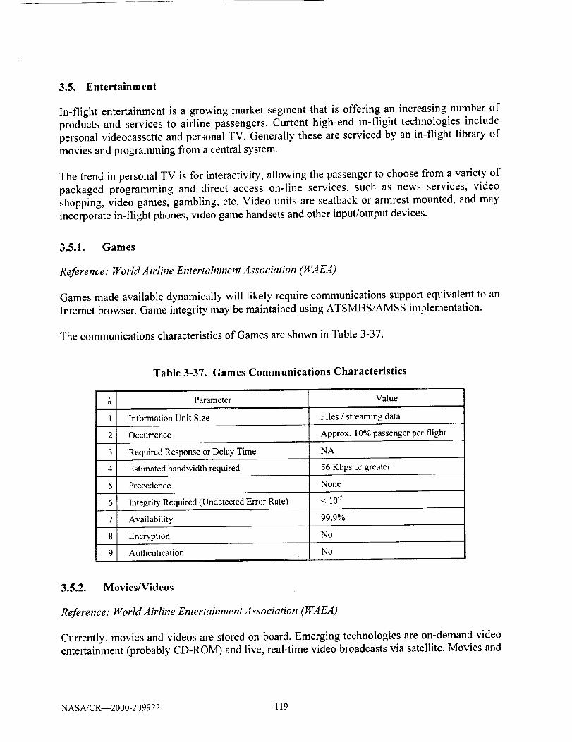
3.5. Entertainment
In-flight entertainment is a growing market segment that is offering an increasing number of
products and services to airline passengers. Current high-end in-flight technologies include
personal videocassette and personal TV. Generally these are serviced by an in-flight library of
movies and programming from a central system.
The trend in personal TV is for interactivity, allowing the passenger to choose from a variety of
packaged programming and direct access on-line services, such as news services, video
shopping, video games, gambling, etc. Video units are seatback or armrest mounted, and may
incorporate in-flight phones, video game handsets and other input/output devices.
3.5.1. Games
Reference." Worm Airline Entertainment Association (WAEA)
Games made available dynamically will likely require communications support equivalent to an
Internet browser. Game integrity may be maintained using ATSMHS/AMSS implementation.
The communications characteristics of Games are shown in Table 3-37.
Table 3-37. Games Communications Characteristics
#
1
2
3
4
5
6
7
8
9
Parameter Value
Information Unit Size Files / streaming data
Occurrence Approx. 10% passenger per flight
Required Response or Delay Time NA
Estimated bandwidth required 56 Kbps or greater
Precedence None
Integrity Required (Undetected Error Rate) < 10 .5
Availability L 99.9%
Encryption No
Authentication No
3.5,2. Movies/Videos
Reference: Worm Airline Entertainment Association (WAEA)
Currently, movies and videos are stored on board. Emerging technologies are on-demand video
entertainment (probably CD-ROM) and live, real-time video broadcasts via satellite. Movies and
NASA/CR--2000-209922 119

videos may be provided by air-to-ground communications accessed by the passengers to select
entertainment venues individually.
The communications characteristics of Movies/Videos are shown in Table 3-38.
Table 3-38. Movies/Videos Communications Characteristics
5
6
7
8
9
Parameter Value
Information Unit Size Files / streaming data
Occurrence Approx. 80% of passengers per flight
Required Response or Delay Time N/A
Estimated bandvAdth required Current applications (satellite TV,
DirectTV, DSS Network, etc.) are inthe 23 - 30 Mbps range.
Precedence None
IntegriPa Required (Undetected Error Rate) < 10 .8
Availability 99.9%
Encryption No
Authentication No
3.5.3. Gambling
Reference." World Airline Entertainment Association (WAEA)
Currently gambling is available on some airlines (e.g., Swissair). Gambling activities could be
provided to passengers from remote gaming facilities such as casinos or lottery offices. This type
of application requires credit card/debit card verification/authorization links or "smart card"
technology for payment.
The communications characteristics of Gambling are shown in Table 3-39.
3.5.4. Shopping
Reference: World Airline Entertainment Association (WAEA)
Shopping while on board is a passenger perk enjoyed today via in-flight phone, although some
high-end in-flight technologies provide shopping by video catalog. Future use of the Internet on
board, or direct digital links to airline shops, or other selected markets would have to be secured
and tracked in the same manner as gambling. "Smart card" technologies for payment serviceswill enhance these services.
NASA/CR--2000-209922 120

The communications characteristics of Shopping are shown in Table 3-40.
Table 3-39. Gambling Communications Characteristics
Parameter Value
Information Unit Size Files / streaming data
Occurrence 10% of passengers per flight
Required Response or Delay Time N/A
Estimated bandwidth required 56 Kbps or greater
Precedence None
Integrity Required (Undetected Error Rate) < 108
Availability 99.9%
EncrTption Yes
Authentication Yes
Table 3-40. Shopping Communications Characteristics
Parameter Value
Information Unit Size Files / streaming data
Occurrence 30% of passengers per flight
Required Response or Delay Time N/A
Estimated bandwidth required 56 Kbps or greater
Precedence None
Integrity Required (Undetected Error Rate) < 108
Availability 99.9%
Encryption Yes
Authentication Yes
#
1
2
3
4
5
6
7
8
9
3.5.5. Automated Teller Machines
Reference." Worm Airline Entertainment Association (WA EA)
ATMs are currently in place on several airlines. They dispense cash from major bank debit and
credit cards, convert US dollars to other currency, and determine a daily exchange rate via
satellite feed. The ATM system operates with the aircrai_'s flight management system to track its
position. Information is transmitted to a receiver on the ground via the satellite network and then
to the appropriate financial organization for verification and authorization.
NASA/CR--2000-209922 121
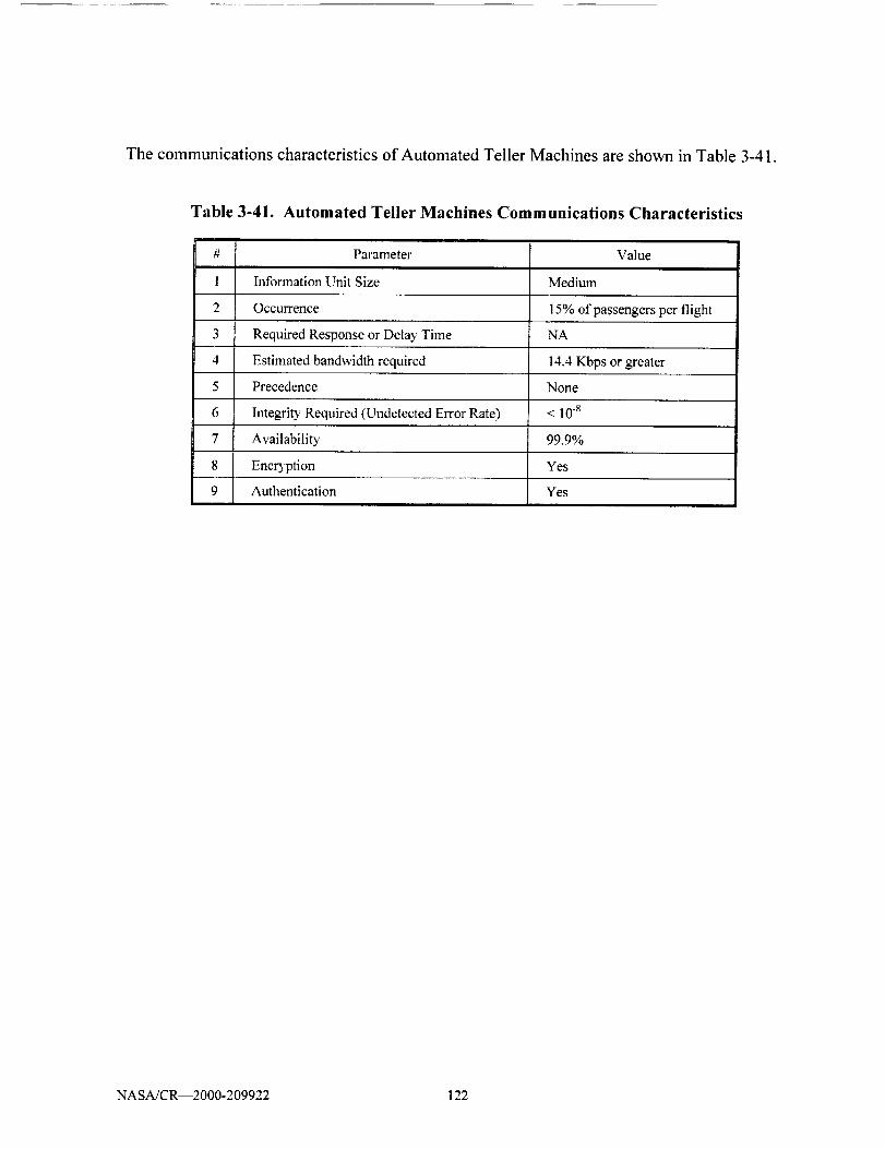
Thecommunicationscharacteristicsof Automated Teller Machines are shown in Table 3-41.
Table 3-41. Automated Teller Machines Communications Characteristics
#
1
2
3
4
5
6
7
8
9
Parameter Value
Information Unit Size Medium
Occurrence 15% of passengers per flight
Required Response or Delay Time NA
Estimated bandwidth required 14.4 Kbps or greater
Precedence None
Integrity Required (Undetected Error Rate) < l0 s
Availability 99.9%
Encryption Yes
Authentication Yes
NASA/CR--2000-209922 122

4. PROTOCOLS/APPLICATIONS COMPARISON
Section 2 presented a review of the ACARS communications plus ATN and TCP/IP protocols
and architectures. The characteristics of the ATM, AOC, AAC, APC, and Entertainment
categories of aeronautical related applications were evaluated in Section 3. For purposes of
analysis, these applications are further grouped into broadcast and unicast Requirements Sets
based on common functions. This section compares the protocol and architectures capabilities to
satisfy the performance metrics identified for the grouped Requirements Sets.
4.1. Communications Requirements Sets
The results of Section 3 analysis are used to construct a finite set of logically grouped
communication requirements. The reader is reminded that these grouping or sets do not
necessarily represent a particular design or implementation. Instead, they represent a system
engineering tool, and indicate the system level communication requirements that are imposed on
any selected network design. Depiction of these requirements sets serves to simplify and allow
an understanding during the later step of comparing the fulfillment of performance against a
requirement for a specific design or implementation. This approach was taken due to the large
number of individual aeronautical related applications and to reduce redundancy in the analysis.
Each requirement set is classified and described using the parameters discussed in Section 3.
The requirement sets into which the applications have been categorized are:
• Broadcast
Unicast consisting of:
Set 1 - Flight Safety Messages
Set 2 - Operational/Administrative Messages
Set 3 - Bulk Data/Streaming Video Services
Set 4 - Flight Safety Digitized Voice
Set 5 - Operational/Administrative Digitized Voice
4.2. Allocation of Applications to Requirements Sets
To facilitate comparative analysis, the Requirements Sets group the requirements imposed by the
various types of applications. Thus, a full range of operational requirements are considered in the
process of comparing the ATN and TCP/IP protocol architectures. The allocation to grouped
Requirements Sets is shown in Table 4-1.
NASA/CR--2000-209922 123
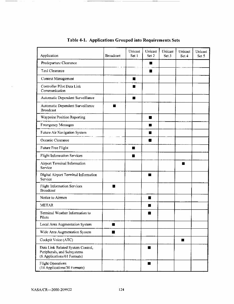
Table 4-1. Applications Grouped into Requirements Sets
Application
Predeparture Clearance
Taxi Clearance
Context Management
Controller Pilot Data Link
Communication
BroadcastUnicast
Set 1
Unicast
Set 2
Unicast
Set 3Unicast
Set 4
Automatic Dependent Surveillance •
Automatic Dependent Surveillance •Broadcast
Waypoint Position Reporting •
Emergency Messages •
Future Air Navigation System •
Oceanic Clearance •
Future Free Flight •
Flight Information Services •
Airport Terminal Information •Service
Digital Airport Terminal InformationService
Flight Information ServicesBroadcast
Notice to Airmen
METAR
Terminal Weather Information to
Pilots
Local Area Augmentation System
Wide Area Augmentation System
Cockpit Voice (ATC)
Data Link Related System Control,
Peripherals, and Subsystems(6 Applications/61 Formats)
Flight Operations(14 Applications/30 Formats)
UnicastSet 5
NASA/CR--2000- 209922 124

Application
MaintenanceOperations( 6Applications)
BroadcastUnicastSet1
UnicastSet2
Airport/RampAreaOperations •
CockpitVoiceOperations(Company)AirlinesGateConnections •
MedicalAssistanceRequests •
CrewScheduleandLodging •Information
MiscellaneousFreetextCrew •Information
Future Applications - Passenger •Handling
APC -Telephony
APC -E-Mail •
APC - Internet Services •
APC - Facsimile •
Games •
Movies/Videos •
Gambling •
Shopping •
Automated Teller Machines •
UnicastSet 3
Unicast Unicast
Set 4 Set 5
4.3. Broadcast Requirements Set
The "Broadcast Requirements Set" is used to define communications from a single sender to
multiple receivers (i.e., point-to-multipoint). For example, the term is sometimes used in e-mail
or other message distribution for a message sent to all members, rather than specific members, of
a group such as a department or enterprise.
Broadcast capabilities for aeronautical messages are accomplished at the Physical, Link and
Applications layers of the OSI reference model. This approach precludes addressing overhead
for bandwidth utilization. This is contrasted with multipoint addressing such as broadcast
addressing in IPv4, and multicast and anycast addressing incorporated into IPv6. The broadcast
transmission directions are:
NASA/CR--2000-209922 125
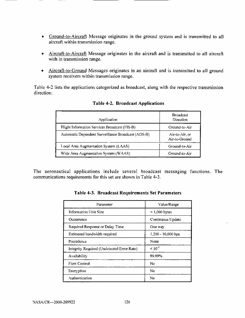
* Ground-to-Aircraft Message originates in the ground system and is transmitted to all
aircraft within transmission range.
• Aircraft-to-Aircraft Message originates in the aircraft and is transmitted to all aircraft
with in transmission range.
• Aircraft-to-Ground Messages originates in an aircraft and is transmitted to all ground
system receivers within transmission range.
Table 4-2 lists the applications categorized as broadcast, along with the respective transmissiondirection:
Table 4-2. Broadcast Applications
Application
Flight Information Services Broadcast (FIS-B)
BroadcastDirection
Ground-to-Air
Automatic Dependent Surveillance Broadcast (ADS-B) Air-to-Air, orAir-to-Ground
Local Area Augmentation System (LAAS) Ground-to-Air
Wide Area Augmentation System (WAAS) Ground-to-Air
The aeronautical applications include several broadcast messaging functions. The
communications requirements for this set are shown in Table 4-3.
Table 4-3. Broadcast Requirements Set Parameters
Parameter Value/Range
Information Unit Size < 1,000 bytes
Occurrence Continuous Update
Required Response or Delay Time One way
Estimated bandwidth required 1,200 - 10,000 bps
Precedence None
Integrity Required (Undetected Error Rate) < 107
Availability 99.99%
Flow Control No
Encryption No
Authentication No
NASA/CR--2000-209922 126

4.4. Unicast Requirements Sets
Unicast is communication between a single sender and a single receiver over a network. An
earlier term (point-to-point communications) is similar in meaning to unicast. An unicast
datagram uses a single destination address.
4.4.1. Unicast Requirements Set 1 - Flight Safety Messages
The unicast network to support flight safety related communication is defined as the Unicast
Requirements Set 1. Table 4-4 defines the basic parameters of this Requirements Set.
Table 4-4. Unicast Set 1 - Flight Safety Messages
Parameter Value/Range
Information Unit Size < 5,000 bytes
Occurrence 100 - 500 per flight
Required Response or Delay Time < 3 Seconds
Estimated bandwidth required 1,200 - 10,000 bps
Precedence Multi-level
Integrity Required (Undetected Error Rate) < 10q
Availability 99.99%
Flow Control Yes
Encryption No (Future desired)
Authentication No (Future desired)
The applications categorized as Flight Safety Messages are:
• Context Management (CM)
• Controller Pilot Data Link Communication (CPDLC)
• Future Free Flight
• Flight Information Services (FIS)
• Automatic Dependent Surveillance (ADS)
Table 4-5 is a comparison of the protocol capabilities to meet requirements identified for Flight
Safety Messages.
NASA/CR--2000-209922 127

Table 4-5. Protocols Supporting Unicast Set1 Applications
Protocol Set 1 Support
ACARS No
ATN Yes
TCP/IPv4 Yes
TCP/1Pv6 Yes
4.4.2. Unicast Requirements Set 2 - Operational/Administrative Messages
The capabilities for unicast transmission of routine operational
communications are defined as the Requirements Set 2. Table 4-6
parameters of this Requirements Set.
and administrative
defines the grouped
Table 4-6. Unicast Set 2 - Operational/Administrative Messages
Parameter Value/Range
Information Unit Size < 5,000 bytes
Occurrence 100 - 300 per flight
Required Response or Delay Time < 30 Seconds
Estimated band_idth required 1,200 - 10,000 bps
Precedence None
Integrity Required (Undetected Error Rate) < 10.6
Availability 99.8%
Flow Control No
Encryption No
Authentication No
The applications grouped into the Operational/Administrative Messages Requirements Set are:
• Predeparture Clearance (PDC)
* Taxi Clearance
• Waypoint Position Reporting (WPT_OS)
• Emergency Messages
• Future Air Navigation System (FANS)
• Oceanic Clearance
• Digital Air Traffic Information Services (DATIS)
NASA/CR--2000-209922 128

• Notice to Airmen (NOTAM)
• METAR
• Terminal Weather Information to Pilots (TWlP)
• Data Link Related System Control, Peripherals, and
61 Formats)
• Flight Operations (14 Applications/30 Formats)
• Maintenance Operations ( 6 Applications)
• Airport/Ramp Area Operations
• Airlines Gate Connections
• Medical Assistance Requests
• Crew Schedule and Lodging Information
• Miscellaneous Freetext Crew Information
• Future Applications- Passenger Handling
• Airline Passenger Communications (APC) E-Mail
• APC Facsimile
• Automated Teller Machines
Subsystems
Table 4-7 is a comparison of the protocol capabilities to meet requirements
Operational/Administrative Messages.
(6 Applications/
identified for
Table 4-7. Protocols Supporting Unicast Set 2 Applications
Protocol Set 2 Support
ACARS Yes
ATN Yes
TCP/IPv4
TCPflPv6
Yes
Yes
4.4.3. Unicast Requirements Set 3 - Bulk Data/Streaming Video Services
The unicast network to support the transmission of large files or bulk data, and to support the
transport of video data streams is defined as the Unicast Requirements Set 3. Table 4-8 identifies
the basic parameters of this Requirements Set.
NASA/CR--2000-209922 129
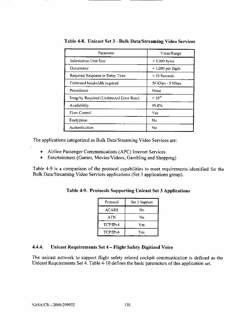
Table 4-8. Unicast Set 3 - Bulk Data/Streaming Video Services
Parameter Value/Range
Information Unit Size > 5,000 bytes
Occurrence < 1,000 per flight
Required Response or Delay Time < 30 Seconds
Estimated bandwidth required 56 Kbps - 5 Mbps
Precedence None
Integrib Required (Undetected Error Rate) < 10.6
Availability 99.8%
Flow Control Yes
Encryption No
Authentication No
The applications categorized as Bulk Data/Streaming Video Services are:
• Airline Passenger Communications (APC) Intemet Services
• Entertainment (Games, Movies/Videos, Gambling and Shopping)
Table 4-9 is a comparison of the protocol capabilities to meet requirements identified for the
Bulk Data/Streaming Video Services applications (Set 3 applications group).
Table 4-9. Protocols Supporting Unicast Set 3 Applications
Protocol Set 3 Support
ACARS No
ATN No
TCP/IPv4 Yes
TCP/IPv6 Yes
4.4.4. Unicast Requirements Set 4 - Flight Safety Digitized Voice
The unicast network to support flight safety related cockpit communication is defined as the
Unicast Requirements Set 4. Table 4-10 defines the basic parameters of this application set.
NASAJCR--2000-209922 130

Table 4-10. Unicast Set 4 - Flight Safety Digitized Voice
Parameter Value/Range
Information Unit Size Small
Occurrence < 40 per flight
Required Response or Delay Time
Estimated bandwidth required
Precedence
Integrity Required (Undetected Error Rate)
Availability 99.99%
Flow Control Yes
Encryption
Authentication
> 1 Sec
> 9,600 bps
None
< 10-5
No (Future Desired)
No (Future Desired)
The applications categorized as Flight Safety Digitized Voice are:
• Airport Terminal Information Service (ATIS)
• Cockpit Voice (Air Traffic Control)
Table 4-11 is a comparison of the protocol capabilities to meet requirements identified for the
Flight Safety Digitized Voice applications.
Table 4-11. Protocols Supporting Unicast Set 4 Applications
Protocol Set 4 Support
ACARS No
ATN No
TCP/IPv4 Yes
TCP/IPv6 Yes
4.4.5. Unicast Requirements Set 5 - Operational/Administrative Digitized Voice
The unicast network to support routine operational, administrative, and passenger voice
communication is defined as the Unicast Requirements Set 5. Table 4-12 defines the basic
parameters of this Requirements Set.
NASA/CR--2000-209922 131

Table 4-12. Unicast Set 5 - Operational/Administrative Digitized Voice
Parameter Value/Range
Information Unit Size Small
Occurrence < 6 per flight
Required Response or Delay Time > 1 Sec
Estimated bandwidth required > 9,600 bps
Precedence None
Integrity Required (Undetected Error Rate) < 10"s
AvailabiliD' 99.0%
Flow Control Yes
Encryption No
Authentication No
The applications categorized as Operational/Administrative Digitized Voice are:
• Cockpit Voice (Company)
• Airline Passenger Communications (APC) Telephony
Table 4-13 is a comparison of the protocol capabilities to meet requirements identified for
Operational/Administrative Digitized Voice.
Table 4-13. Protocols Supporting Unicast Set 5 Applications
Protocol Set 5 Support
ACARS No
ATN No
TCP/IPv4 Yes
TCP/IPv6 Yes
4.5. Why Transition to IPv6 - What is Wrong with IPv4?
The IPv4 address space problem is just one of the motivations to transition to IPv6. However, the
address space problem may not be the only motivation. One could argue that today's IPv4 host
implementations lack such essential features as autoconfiguration, network layer security, and
others. Thus one could argue that the existing IPv4 host stack implementations may no longer be
adequate to address the requirements of the current networking environment. IPv6 is intended to
address most of the inadequacies in the existing IPv4 implementations.
NASA/CR 2000-209922 132

In fact, all of the new functionality provided by IPv6, except for the increase in the size of the IP
address space and stateless address autoconfiguration, could be retrofitted into IPv4. With
respect to the ability to support hierarchical routing, one could observe that it is not the size of
the address space (32 compared to 128) but the address assignment that matters. So, IPv6 does
not affect the ability to use hierarchical routing in the Internet. Functionality that could be
provided by the IPv6 routing header is already defined for IPv4 through such mechanisms as
Source Demand Routing Protocol (SDRP) [RFC 1940] or Generic Routing Encapsulation (GRE)
[RFC 1702]. DHCP is rapidly gaining acceptance in the marketplace, thus providing a
mechanism for state address autoconfiguration with IPv4. Support for graceful renumbering,
similar to IPv6, could be implemented with IPv4 [DHC-RENUM]. Mechanisms to provide
network layer security for IPv4 are quite similar to IPv6. Support for mobility is already defined
in IPv4 and is expected to form the base for supporting mobility in IPv6. Support for the
Resource Reservation Protocol (RSVP) is already defined in IPv4 and is implemented by several
vendors. Most of the functionality provided by NDP could be realized with IPv4 as well.
While in principle most of the IPv6 functionality could be retrofitted into IPv4, in practice doing
this would certainly require changes to the existing IPv4 software. Even if fewer changes were
required, as opposed to implementing IPv6, the number of changes should not be
underestimated. As a result, the adoption of IPv6 could be influenced to a large degree by
whether vendors (and especially host vendors) would continue to improve their IPv4
implementations, or whether they would shift their major focus from IPv4 to IPv6, and would
treat IPv4 as legacy technology.
4.6. Network Address Translation
One technology that supports connectivity in the presence of non-unique addresses is NAT (RFC
1631). NAT technology allows each organization connected to the Internet to reuse the same
block of addresses (for example, the addresses defined in RFC 1918), while requiring only a
small number (relative to the total number of addresses used by the organization) of globally
unique addresses for external connectivity.
One could argue that use of NAT devices represents a significant departure from the current IP
routing and addressing architecture. However, widespread deployment of mediating gateways
indicates that the traditional IP-level connectivity may not be that crucial, and that the
connectivity provided by such gateways could be sufficient.
Use of NAT devices could be viewed as an evolution of application layer gateways toward more
simplicity of operations, more transparency to the end users, more flexibility with respect to
supporting various applications, and better performance. At the same time, use of NAT devicesshould be viewed as an evolution of routers toward supporting less stringent requirements on the
address assignment (allowing non-unique addresses).
In addition to enabling the Internet growth beyond what could be accomplished with IPv4 and
the current routing and addressing architecture, use of NAT devices allows support of
NASA/CR--2000-209922 133

hierarchicalroutingwithout requiring wide-spread renumbering. The only addresses that would
need to be changed when an organization changed its Internet service provider would be the
globally unique addresses that the organization uses for its external connectivity. Moreover,
because information about these addresses is localized to the NAT devices, only these devices
would need to be reconfigured.
NAT devices could also play an important role in the IPv4 to IPv6 transition. These devices
would allow the interconnection of hosts that have IPv6-only addresses (hosts that do not have
IPv4-compatible addresses) with hosts that have IPv4-only addresses. If assigning globally
unique IPv4 addresses would become impossible (due to the exhaustion of the IPv4 address
space) before a sufficient number of the Internet hosts would transition to IPv6, then NAT
devices would allow continuing (and completing) the transition, even in the absence of the
globally unique IPv4 addresses.
4.7. Protocols/Applications Comparison Conclusions
In this section, we compared the ability of various protocol architectures to support application
groups identified in Section 3 based on a set of metrics. The key metrics used were integrity,
availability, quality of service (QoS), and security. Broadcast applications in the aeronautical
environment require a bit efficient transport system. Therefore, it is common for aeronautical
broadcast applications to interface directly to the lower layer of the architecture (subnetwork)
bypassing the transport and network layers. Because of this we did not perform a comparative
analysis for broadcast applications.
ATN and TCP/IPv6 protocol architectures have the required functionalities to support all
applications comprising Requirements Set l, Flight Safety Messages.
ACARS, ATN, TCP/IPv4 and TCP/IPv6 protocol architectures have the capabilities and features
required to support all applications in Requirements Set 2, Operational/Administrative Messages.
ACARS being a legacy protocol was designed to support data only applications and therefore
does not have the protocol features to support stream video services. ATN is in the process of
defining additional standards to support other services not specified in the initial SARPs.
Therefore, at present as specified by the SARPs, ATN does not have the capabilities to support
Requirements Set 3, Bulk Data/Streaming Video Services. The Internet community has been
actively developing specifications for Streaming Video type services. Therefore, TCP/IPv4 and
TCP/IPv6 can support Requirements Set 3, Bulk Data/Streaming Video Services.
ACARS being a legacy protocol was designed to support data only applications and therefore
does not have the protocol features to support Requirements Set 4, Flight Safety Digitized Voice.
ATN is in the process of defining additional standards to support other services not specified in
the initial SARPs. Therefore, at present as specified by the SARPs, ATN does not have the
capabilities to support Flight Safety Digitized Voice services. The Internet community has been
actively developing specifications for Voice over IP services. Therefore, TCP/IPv4 and
TCP/IPv6 can support Requirements Set 4, Flight Safety Digitized Voice services.
NASA/CR--2000-209922 134

Likewise, ACARS and ATN do not have the protocol features to support Requirements Set 5,
Operational/Administrative Digitized Voice. TCP/IPv4 and TCP/IPv6 can support Requirements
Set 5.
NASA/CR--2000- 209922 135

5. TRENDS FOR THE FUTURE
As part of the scope of analysis covering the use of ATN and TCP/IP networks as the means of
transport for the various aeronautical applications, CNS has been tasked to make an assessment
of the future probability that the air transport industry will adopt the TCP/IP set of network
protocols. The task, however, was understood as not meaning to imply an exclusive condition of
adopting one approach over the other. It is instead intended to draw out the factors that will be
present in the future marketplace, including the government sector. These factors will drive or
pace the continued adoption of either of the two network technology approaches. The result is, of
course, to forecast if either technology will continue to be adopted on a wide-scale
implementation basis. Of course the study investigators realized that any forecast of business
activity is a risky business -- if not opportunity to be fully embarrassed. However, if the reader
can tolerate the avoidance of making point assessments or hard predictions, then what can be
done is to look at a selected set of predictive factors. From these factors the reader may draw his
own conclusion.
The next key agreement with the reader is the selection of the predictive factors. Then, of course
the reflection on past behavior (under the theme that one can extrapolate future behavior by
looking at trends) must be built into a narrative. Up to this point, the technical performance and
technical differences of the ATN and of the TCP/IP protocols has been the subject of this study
report. To analyze past behaviors requires adding the dimensions of economical and industrial-
social choices that accompany any change.
For the forecast, the following four predictive factors or indicators are discussed:
• Achieving agreement in regulatory and standards bodies associated with safety and
regularity of flight
• Readiness to commit capital infrastructure investment to support change
• Past trends in adopting new technology within the air transport industry
• Trends in global communications
5.1. Achieving Agreement in Regulatory and Standards Bodies
There are international, national and industry forums to develop standards so that communication
between end systems can take place in an efficient way. Although these groups share a common
goal (open communication among end systems), achieving common ground has been elusive.
Recently, these groups have gone from a state of holy war to peaceful coexistence, which has
benefited the user community.
The architects of the OSI protocol reference model have identified various drawbacks in the OSI
model since its initial implementation. Since 1983, experts have claimed that the organization of
NASA/CR--2000-209922 136

the OSI upper layers(Application, Presentation,andSession)asdescribedin the OSI referencemodel is a mess and needs to be restructured. Also, network architectures, such as the
Aeronautical Telecommunication Network (ATN) which use the ISO protocol architecture for
air-to-ground communications, have devised methods to bypass the presentation and session
layers. This is done to reduce the overhead and eliminate unnecessary functions present in these
two layers.
Recently, ISO extended the application layer structure to allow a single control function to
supervise a set of application service elements. Also, they have revisited the entire upper layer
architecture. They now essentially allow implementations to slice the upper layers vertically and
ultimately collapse the upper layers into a single, object-oriented service layer. The Extended
Application Layer Structure (XALS) and revised OSI upper layer architecture are under study in
the ISO defined Application Service Object (ASO). The ASO will contain multiple application
service elements, some formed by grouping session functional units into application service
elements. The result is the elimination of the session layer.
The existing Presentation layer functionality will be subsumed within a new association control
service element, which will offer an association data service. As a result, the presentation layer
will be removed from the OSI reference model as well. This allows the ASO association control
service element to directly interface with the OSI transport layer, These developments in a sense
align the OSI architecture more closely with the TCP/IP protocol architecture. It also reduces the
overhead and protocol complexity.
The ISO transport protocol TP4 and the TCP are not only functionally equivalent but
operationally similar as well. A 1985 study performed jointly by the U.S. Defense
Communications Agency and National Academy of Science concluded that TP4 and TCP are
functionally equivalent and essentially provide similar services. The TP4 to TCP comparison is
addressed in Section 2.
At the network layer ISO supports Cormectionless Network Protocol (CLNP) and the TCP/IP
protocol architecture supports the Internet Protocol (IP). The CLNP and IP are functionally
identical and both are best effort delivery network protocols. The major difference between the
two is that CLNP accommodates variable length addresses, whereas IPv4 supports fixed 32 bit
addresses. (IPv6 supports a larger address space.) In Section 2, the functions of CLNP are
compared to those of IPv4.
5.2. Industry Capital Investment
To transform the current air transport industry communications infrastructure from today's
legacy, character-oriented and voice intensive messaging to that of the bit-oriented messaging
and automated applications as defined by ATN standards requires the capital investment by the
following participant groups:
• Civil Air Authorities (CAA)
• Commercial airlines
NASA/CR--2000-209922 137
• Business aviation
• General aviation
• Military aircraft
• Airport operators
• Communication service providers (public/private)
Several studies have been conducted to understand the investment analysis or business case for
making this industry capital commitment (reference the recent RTCA activity defined by the
activities of the CNS/ATM Focused Team (C/AFT). The results show favorable benefits versus
cost outcome but do not provide the source of funding commitment to proceed. This
commitment requires the individual members of the groups to work within their justification
framework and funds allocation schemes to tradeoff the use of monies to support the changes.
Thus, pure economic decisions slow the infrastructure change due to the size of the funding
required. This self-paced approach leads to difficulty in achieving a critical mass of members
equipped with the new technology. The size of the investment must be understood in order to
appreciate the funding problems faced. To construct this total funding requirement is beyond the
scope of this study, but a top-level summary can be depicted to support the understanding. This
is done segment by segment for the groups defined earlier.
From Table 5-1 it can be summarized that the range of industry investment to achieve
interoperability using the ATN approach requires a total global capital investment of approx. 18 -
19 Billions US dollars. This figure does not include the upgrade of simulators or the human
training cost of making the transition. It would be safe to estimate approximately a 20 billion
dollar industry investment that could grow by 50% when applying escalation factors. With the
exception of first-world nations, programming of this size investment will have to be paid back
by the operating airlines. This is a burdensome role for most of the world's carriers. Furthermore,
the absence of available and synchronized funding leads to islands of new functionality amongst
old procedural areas and the benefits are questionable since even the latest aircraft must be
backwards compatible. Indeed the airline industry has already concluded that replacement or
upgrade of legacy aircraft avionics is not economically feasible and thus the introduction of new
avionics will be performed using newly manufactured aircraft.
Thus, it is a safe assessment to predict that the transition to bit-oriented CNS/ATM will be
consistent with prior technology changes undertaken by the air transport industry; i.e., these
changes occur at about the rate of introduction of major new airframes. This trend change cycle
history is described in the next section.
NASA/CR--2000- 209922 138

Table 5-1. Investment to Achieve Global lnteroperability
Group
Commercial Air
Carriers
Commercial Air
Carders
Type
Avionics Upgrade-
Radio/CMU/FMS(one
media only VHF, Sat,
I-It)
Ground Based Systems
- Op Control (upgradelegacy system)
Business Jet Avionics Upgrade
Avionics UpgradeGeneral Aviation
(Instrumented)
Each Member's
Investment
Basis/Rational
Approx. $500K per
aircraft (add $200Kfor each additional
media)
Midsize to largeairline $5M
Small Airline $1M
Estimated Range of TotalMembers
8,000 - 10,000 Aircraft
(3,000 with two Media)
120 - 200 Airlines
600 - 800 Airlines
Total GroupInvestment
(Millions of SUS)
$4.600 - 5,600
600- 1,000
600- 800
Approximately 3,000 - 4,000 600 - 800
$200K per aircraft
50,000 150Approximately $30K
per aircraft
Military Aircraft Avionics Upgrade $250K per aircraft 15,000 3,750
CAA (Major) Automation Upgrade $100M 50 5,000
CAA Limited Automation
Upgrade
Communication
Services Provider -Data Link VHF
Ground Station
Replacement 1
$20M
$150M MajorContinental Area
VHF
$25M (achieve
99.999 availability)
$5M per network
$iM per major
airport
Continued Upgrade of
existing service
Upgrade of routers
Tower facility upgrades
100
US, Europe, Russia,
China, South
Pacific/Indonesia, South
America and Africa
(equals six continental
areas)
ARINC and SITA
ARINC
SITA
Other 3 Major Telecomm
Providers
300 - 400 world wide
Communications
Service Provider -
Data Link Satcom
Communications
Network
Airport Facilities/
Towers
2,000
600
50
25
300-400
5.3. Trends in Adopting Technology
The purpose of this section is to review several key factors in the behavior of the air transport
community that would indicate the rate of which technical change is undertaken as relates to the
IT and communications infrastructure used to manage the movement and efficient operation of
aircraft operations. For this discussion, the focus will be the past history of commercial
aviation's use of RF based Data Link.
Today's air transport industry uses a mix of voice and data communications that has evolved
over the last half of the century to provide a safe and low cost means to travel on a global basis.
NASA/CR--2000-209922 139
In viewing the history of commercial aviation's use of Data Link technology, it must also be
remembered the commercial marketplace's use of this technology took place at least 10 to 15
years after it was in already in use by the military sector.
Commercial air carriers' use of data link for revenue operations is an interwoven history of using
both Satellite and VHF radio techniques. Indeed, Pam Am Airlines first demonstrated 75-baud
Teletype via Satellite in the mid-60s -- but we will hold on satellite and first follow the VHF
Data Link path. By more than 15 years after the mentioned Pam AM event, in the late 70s, the
airlines had begun to operate the ACARS VHF Data Link system with a limited number of
equipped planes. ACARS started with a few messages to capture the Out, Off, On, In status of
the aircraft location with respect to the airport runway and gate. The growth of ACARS equipped
aircraft was slow. After 10 years of ACARS service, many major carriers like Delta, Pan AM,
and Eastern were not using the data link -- while many others had only partial aircraft fleet
equipage. This was due to the cost of internal infrastructure change, application development,
avionics retrofitting, and a marginal quality of service. By this time, there were three service
providers: European based SITA (AIRCOM), Air Canada, and ARINC (ACARS).
Unfortunately, the systems used by each required different avionics to accommodate the VHF
communications. In the late 80s aircraft owners in the US began to see the benefits of a Data
Link to the "hub and spoke" method of flight operations. At the same time ARINC's ACARS
Service started to turn towards a high quality service with the ability to handle an increased
demand. This was due to the investment and deployment of new ground station components that
had been defined to handle the bit-oriented messages for the Enhanced ACARS (EACARS).
However, the airlines failed to back the deployment with companion avionics. Instead, the bit-
oriented standard changed to AVPAC (aviation VHF packetized aircraft communications). Then
the services providers together with the avionics vendors began in about 1989 to invest in
upgrading ACARS to the AVPAC set of standards. The plan (just like with ACARS) was that
the airline companies would follow with the purchase and deployment of a bit-oriented capable
avionics package. But, this did not happen. In the nineties the industry VHF Data Link can besummarized as:
• Still character-oriented, having had two false starts at transitioning to bit-oriented
improvements.
• Beginning to provide several key applications which were coupled to "turning planes" atthe hub.
• Being available in North America, Europe and the MidEast (but using different
implementations).
• Equipped in less one quarter of the world's commercial aircraft.
• Providing stable quality of service.
NASA/CR--2000-209922 140

Meanwhile an ICAO Committee had been formed in 1981 to begin to define a satellite-based
means of air traffic management for the oceanic areas. The basis of the concept was that by use
of a satellite data link that would send a constant stream of position reports (called Automatic
Dependent Surveillance (ADS) messages), automation could provide the means to increase
capacity of the fixed track oceanic routes. Of course, the entire range of Air Traffic Management
Center interactions would be included as well the improvement of onboard navigation avionics.
This meant a need to define not only the air-to-ground data link, but the entire end-to-end ground
interactions between Air Traffic Service Providers. The concept fostered by this ICAO
committee became widely known as the Future Air Navigation System (FANS) Concept.
The FANS Concept started the parallel activities within the RTCA and AEEC committees to
define the technical specifications of satellite components and related signaling standards.
During the mid-eighties, the airline companies formed a separate company (AVSAT) which was
to launch the geostationary satellite space segment and provide a highly available data link
service. By 1986 it was clear that a new communications protocol would be needed to support
the interoperability of air traffic operations.
Since this was still the early era of OSI being the state of the art in open systems standards, what
resulted was a seven-layer architecture of industry unique definition. What was defined is known
as the ATN -- and the emphasis was internetworking between networks and wireless
subnetworks. The slow progress on the evolution of a bit-oriented VHF Data Link has been
covered, but what about the progress towards a satellite wireless subnetwork.
The previously mentioned airline company (AVSAT) was disbanded in 1988 after the realization
that the investments of $6 - 9 Billion to put into place a standalone Aeronautical Satellite Service
was not a practical investment for only one industry to undertake. Instead, the owners of ARINC
and SITA formed a Joint Venture to use the space resources of the existing IMMARSAT
Corporation and the Earth Station resources of its signatories (Earth Station Operators) to deploy
a low gain (10,000 bps) service. First operation of this Satellite Data Link was started in 1991
and involved a limited number of newly purchased United 747-400 aircraft reporting Way Point
Position Reports in on Pacific Routes.
By 1998 there were about 300 planes worldwide using the Satellite Service that also provided a
means for passenger telephony. ARINC and SITA had disbanded their Joint Venture by 1995,
but individually maintained a satellite service. Also, the FANS spurt of interest had mislead
some major nations to declare that they would develop their own national satellite space system
to support air traffic management within their sovereign air space (e.g., US-AMSC, UK, Japan,
and the Indonesia).
This lack of agreement on the use of one space-based approach continues today and
IMMARSAT now also offers a satellite service. Having to be content with switching to domestic
monopoly and/or mandated government provided satellite providers increases the likelihood of
not achieving interoperability or of achieving an economically priced service.
NASA/CR--2000-209922 141

In summary, the very slow growth in Satellite equipped aircraft was due to the high cost of about
$500-600K for the outfitting one aircraft with satellite avionics. The justification behind the
business case to equip aircraft just was not clear - either based upon savings in operational costs
or increased revenue from passenger telephone usage. The stage is now set for judging how the
ATN will develop a set of compliant supporting wireless subnetworks
By the early part of 90s, the draft of the communications architecture for the ATN layered
standards was well defined. The satellite technology was understood and had been demonstrated.
Lastly, the means of achieving bit-oriented VHF communications was thought to be understood
and the readiness to equip aircraft agreed to. Also, in 1991 more than 50 of the member nations
voted to adopt the ICAO FANS Concept and its related ATN. (This became know as
CNS/ATM.)
Since then, and continuing until today, there have been a number of attempts to interest the
international industry to move forward and implement the CNS/ATM concepts. The first of these
was a MITRE led effort called the ATN Project in which major participant firms, while investing
their own resources, agreed to coordinate the activities that would lead to demonstration of an
integrated ATN based on Satellite and VHF communications using revenue aircraft. The size of
ftmding needed for the limited demonstration eventually caused the project to effectively cease.
During the same timeframe, the FAA's modernization program was consuming attention within
the FAA. At the same time, the Gulf War had depressed the earnings of the entire air transport
industry so that any new capital or demonstration R&D funding was effectively not available to
foster new technology moves. It was an era of "why can't we use the existing character-oriented
VHF?" to try out some of the FANS concepts.
As a parallel and important related development, the FAA in 1992 had started to use ACARS to
send the Predeparture Clearance (PDC) message from the Airport Tower Controllers to the pilot.
As an aside, another ATS message (the DATIS message) was to be implemented shortly after
PDC. However, the tower controllers blocked the effort as part of other concerns and it took
another five years to deploy DATIS. Nevertheless, the PDC Air Traffic Service message was a
key first, in that it coupled ATS traffic onto the previously AOC designated media.
The combination of VHF ACARS PDC, and Satellite Way Point Position Reports flowing over
the AOC VHF and Satellite Data Link supported the idea that the efficiency and accurate nature
(better than voice) of data the communications link should be fostered - why wait for a "Full"
compliant ATN. All of this set the framework for the Boeing company to foster the FANS I
effort and, later, for Airbus to foster the FANS A. The RTCA and AEEC formed a set of two-
way data link messaging standards (DO-219) together with unique interface gateway standards.
By 1996 the use of the FANS character-oriented data link was in place on several South Pacific
routes flown by United Airlines.
But what of ATN? The Europeans had picked up their own ATN Project (it grew to PETAL I
and today's PETAL II). In the U.S. MITRE pushed the idea that a government funded
development of the "ATN Router" was the key to make the ATN concept economically feasible.
NASA/CR--2000-209922 142

This, in 1996,lead to the formation of the ATNSI which is currently in the process, with its
contractors, of building the certified airborne router to be delivered in mid-2000. In theory,
industry will use this to foster the equipage of aircraft with bit-oriented avionics.
The story would seem simple from point this forward. Except that like ACARS, which spawned
different VHF applications from competing service vendors, the idea of a bit-oriented VHF Data
Link has spawned competing design implementations that are known as VDL Modes 2, 3, and 4.
Each mode has its community of interest. This reduces the possible path to achieving
interoperability on a global basis as additional avionics equipage would be required to
communicate while flying in these different subnetworks. Three other data link developments are
also within the future picture: Mode S, MITRE's UAT, and HF Data Link. In other words,
capital investment requirements or factors other than technical feasibility will slow the change to
a set of data link subnetworks which are capable of supporting the ATN.
Today the FAA has charted CPDLC I and IA, which will provide an end-to-end implementation
for a subset of ATN. This was fostered by the work of many, but is in a large part due to the air
space capacity modeling performed by American Airlines. The RTCA C/FATM Task Force
enhanced this modeling effort.
Senior executive members of the American Air Transport Association used this capacity
forecasting work to underlay their communications to the FAA that the concept of "Free Flight"
was the only viable means to increase the capacity of the nations airspace system. However it
will be towards the end of 2002 before the system segments are in place for this effort, and into
2008 before the first ATN related efforts are deployed throughout the US. It is also interesting to
mention that the European efforts and US CPDLC are not interoperable.
The study authors realize that the preceding, short abridgment of some the activities along the
path of ATN and data link technology can be challenged as a negative review of data link as well
as possibly missing some key events. It was only our purpose, however, to collapse the
timeframe and to see if any predicative behavior could be identified. Looking at this history, the
conclusions that can be drawn which relate to possible acceptance by the airlines and CAAs of
the world of the idea of using a TCP/IP transport mechanism are summarized in the following:
Most important to any technology change is to have it coincide with the cycle of the
introduction of a new aircraft model or major modification upgrades (like 747-400 in the
early satellite stage). It is noted that the introduction of the Boeing 777 was skipped as
the launching point for the ATN related avionics. Add to this the fact that some carriers
(e.g., Northwest Airlines) have definite strategies to extend the useful life of an aircraft to
the maximum and thus delay new aircraft introduction.
The time between the development of standards and implementation of a widely used
technology change can be measured in cycles taking more than 10 years and is often
closer to 20. ACARS took 10 years to begin to get wide use. Although ARINC is
deploying VDL Mode 2 capable ground stations, no airline has installed VDL Mode 2
avionics. Thus 20 years later, the airlines basically use a character-oriented datagram
NASA/CR--2000-209922 143

system. FANS started in 1981 and was approved in 1991. The first FANS trials using
character-oriented links took place in 1996 and continue with very few aircraft today. The
first FAA location (Miami Center) will start the CPDLC trials beginning in late 2002.
• Commercial airlines tend to follow strict business-case models and do not retrofit to
obtain the new technology unless there is a clear economic benefit.
New technology changes start because one strong player was willing to commit the
resources to pursue the initiative generally on a small, limited basis. This player could
provide buying authority to get all parts of the system to work together. United Airlines
fostered the satellite Data Link activity by directing ARINC and by purchasing equipped
aircraft. Lack of progress in the large-scale automation upgrades within the Oakland
Oceanic Center stopped full realization of the benefits. The corollary to this is: that once
started by a few early adopters, the ability to get all others to join is highly unlikely until
a clear business case is available; i.e., acquisition cost is the most important factor in
discretionary changes.
• The ground controllers adoption of changes in their workload and procedures requires
time and testing that is significant and often overlooked by designers.
The need for flights to carry the passenger and cargo is assumed to increase although
only few new large airports are expected in the next 10 years and increasing the number
of gates at existing airports is a slow process.
The use of the same communications channel to send messages categorized as ATC and
AOC is not to be assumed as receiving prior blanket FAA approval. The step taken to
send the ATS messages PDC and DATIS on the same ACARS channel with AOC and
AAC was accepted because of the quality of voice back-up capabilities. Sending the ATC
related ATN message traffic over channels including APC will have to be fully reviewed.
5.4. Trends In Global Communications
There are a numerous indicators applied for analysis of communications industry trends. The
International Telecommunications Union (ITU) defines 59 discrete statistical data elements
covering 12 categories for global communications trend analyses. This section is an analysis of
selected industry-standard statistical indicators for determining broad global communications
trends. Specific measures evaluated are communications infrastructure, socioeconomic changes
and technology indicators.
5.4.1. Communications Infrastructure
The infrastructure trends considered are teledensity, cellular telephone capacity and satellite
communications. These measures provide insight into where future infrastructure growth is
likely to be greatest, what the infrastructure technological composition is likely to be in the
future, and how the infrastructure capacity will be used in the future.
NASA/CR--2000-209922 144

During the 1980s, there was explosive (i.e., orders of magnitude) growth in communications
infrastructure systems at all levels - globally regionally, and locally. Commercial satellite-based
communications established the "global communications" paradigm. Regional growth was in
fiber optic and wideband microwave radio backbone networks. Growth at the local level was in
the form of Metropolitan Area Networks (MANs) interconnecting nodal campus networks and
Local Area Networks (LANs). For communications, the 1990s was the "Internet decade" which
combined PC-based digital networking and software technologies for utilizing the expanding
global communications infrastructure. Figure 5-1 provides indicators that the technical and
economic forces that fostered this growth in the past will continue to influence global
communications infrastructure growth in the future.
Compound Annual Growth Rate 1990-1997
Telephone-Lines
MobileSubscribers
Internet Hosts
6%
52%
90%
Years it took to reach 50 million users
Telephone
Radio
PC
Television
Internet
_ 74
Notes: 1. The latest Compound Annual Growth Rate data is valid for mid-1998, not end-year.
2. The growth rate shown are annualized rates.Source: ITU World Telecommunication Indicators Database, Network Wizards, Compaq, RIPE.
Figure 5-1. Global Communications Infrastructure Growth Trends
NASA/CR--2000-209922 145

5.4.1.1. Teledensity
Teledensity is defined as the number of main telephone lines per 100 inhabitants. The term
"main telephone line" refers to Direct Exchange Loops (DELs) connecting end instruments (i.e.,
telephones) to a local telephone exchange, and excludes telephones indirectly connected through
a Private Branch Exchange (PBX). It is used as a measure of the "plain old telephone service"
(POTS) infrastructure of a country. Figure 5-2 is a statistical map of global teledensity.
Based on ITU statistics from 1990 through 1998, global teledensity is increasing at average
annual rates of 5% or less in developed countries (e.g., 2.4% in the U.S.) but often at more than
10% in developing countries (e.g., 11.8% in Mauritania). In 1996, global teledensity ranged from
0.07 in Cambodia to 99 in Monaco. Although growth rates for underdeveloped economies appear
positive, they can be misleading - from 1996 to 1997, teledensity in Mauritania grew by 27.9%,
from 0.43 to 0.55 lines per 100 people.
_m_
Source: ITU
Figure 5-2. Global Teledensity
2
5.4.1.2. Cellular Telephone Capacity
In the same period, 1990 through 1998, the average annual growth rate of cellular telephone
subscription was approximately 40% in the U.S., 270% in Brazil, 160% in Argentina, and
essentially non-existent in Mauritania. Namibia, another underdeveloped African nation, had
100% growth in cellular subscriptions from 1996 to 1997. Although "subscriptions" is a measure
of capacity utilization, it is directly correlated to infrastructure capacity.
5.4.1.3. Satellite Communications
Several factors influence satellite communications capacity, including the limited availability of
orbital slots, space segment delivery and operational costs. In a 1996 U.S. Department of
NASA/CR--2000-209922 146

Commerce Satellite Communications Industry Update, it was reported that U.S. companies
operated 32 domestic satellites as of September 1995, carrying 721 total transponders (an
average of about 22 transponders per spacecraft). Since 1997, low-earth orbiting (LEO) satellite
capacity has been introduced and, as commercial viability has not yet been realized, it is largely
excess capacity.
According to a Strategic Policy Research, Inc. study for the Satellite Industry Association, in
1996 there were an estimated 156 satellites providing global (nonmilitary) communications
capacity. As aging satellites are replaced, the next generation of spacecraft incorporate
technological advances such as smaller components and improved high-powered amplifier
performance.
Based on ITU and Satellite Communications Association (SCA) reports, the trend in satellite
communications capacity utilization in developed countries is for direct broadcast television. In
developing countries, the trend in satellite communications capacity utilization continues to be
for long-distance voice and data telecommunications.
5.4.2. Socioeconomic Changes
The most significant socioeconomic trends affecting global communications are privatization,
electronic commerce and declining costs for implementing high-capacity global infrastructure.
5.4.2.1. Privatization
Historically in many countries, telecommunications capacity was provided solely by a state-
owned monopoly termed a Public Telephone and Telegraph (PTT). Over the past decade, thePTTs have been converted to commercial enterprises, transforming the markets from
monopolistic to competitive. The results of this transformation have been two-fold:
• Increased growth in the communications infrastructure.
• Lower costs for both local and long-distance communications services.
In cases reported, privatization has resulted in rapid infrastructure growth. In some Least
Developed Countries (LDCs), there has been more growth in the communications infrastructure
since privatization than in the preceding decades combined. In the Philippines, for example, the
incumbent Philippine Long Distance Telephone Company (PLDT), has doubled the size of its
network since the introduction of "competition" in the local exchange market.
Virtually every ITU case study shows that competition results in lowering the costs for
telecommunications services. In turn, there is sustained market demand for all forms of
communications offered.
NASA/CR--2000-209922 147
5.4.2.2. Electronic Commerce
The Internet is primarily responsible for the phenomenon known as electronic commerce (or e-
commerce). According to the 1998 ITU World Trade Development Report, electronic commerce
is expected to grow from $8 billion in 1998 to $327 billion in 2002. As shown in Figure 5-3, the
growth of Intemet hosts from approximately 40,000 in 1990 to more than 43 million in 1998 is
an indicator of the potential global market value of e-commerce.
5.4.2.3. Declining Costs for Implementing High-Capacity Global Infrastructure
According to the 1998/1999 British Telecom (BT) World Communications Report, technology
has transformed the cost of new fiber optic submarine and terrestrial cable transmission systems,
which are now at the core of all international telecommunications. Equipment and installation
costs per voice path on the trans-Pacific route fell from $73,000 in 1975 to only $2,000 in 1996,
and the next cable will cut that cost to less than $200. In the early years of the next decade, cost
per voice path could be as low as $5. The report further cites that, in the highly competitive
transatlantic route, prices are now falling by about 30% per year. Over the past five years, the
average price of a three minute, peak-rate US-Europe phone call has fallen from just over $4 toabout $1.50.
5.4.3. Technological Indicators
While contributing to increased global communications infrastructure capacity and reduced
costs, technological advances provide indicators of future global communications services.
Technological trends include changing service offerings, techniques for improving capacity
utilization and the technology growth areas.
5.4.3.1. Changing Service Offerings
Among the emerging communications service offerings, Internet voice (i.e., voice over IP) is
considered a valid indicator of global communications technology trends. Although it is not as
yet widely used, this technology is the basis of major technology research and significant
infrastructure investments. The implications for global communications are advances in
packetized transmission technology, low-cost (possibly no-cost) long-distance voice
communications and broad, rapid acceptance of internetworking protocol standards.
5.4.3.2. Improved Capacity Utilization Techniques
There are two technologies which indicate future trends in global communications capacity
utilization. The first is digital compression techniques used for direct broadcast satellite (DBS).
Using digital compression, transponder capacity is increased and television programming can be
delivered globally at lower costs. The trend indicated is that satellite communications capacity
utilization for television broadcasting will exceed voice or other types of digital data.
NASA/CR--2000-209922 148
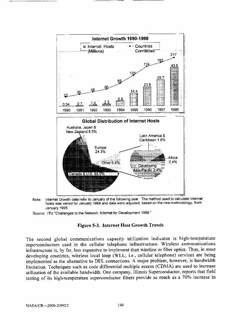
Internet Growth 1990-1998
!a Internet Hosts + Countries 1
...................................._ (Milliohs) _ Connected---J ....217
1___4_.5
29,7
0.040.7 ....1990 1991 1992 1993 1994 1995 1996 1997 1998
Global Distribution of Internet Hosts
Australia,Japan&New Zealand6.3%
LatinAmerica&Caribbean1.6%
Europe : : =24.3%........ ' .....:-_ii :_": Afr ca
..... !! _ AOZ....... u.'_/o
Note: InternetGrowth data refer to January of the following year. The method used to calculate Internethosts was varied for January 1998and data were adjusted, based on the new methodology, fromJanuary 1995.
Source: ITU "Challenges to the Network: Internet for Development 1999."
Figure 5-3. lnternet Host Growth Trends
The second global communications capacity utilization indicator is high-temperature
superconductors used in the cellular telephone infrastructure. Wireless communications
infrastructure is, by far, less expensive to implement than wireline or fiber optics. Thus, in most
developing countries, wireless local loop (WLL; i.e., cellular telephone) services are being
implemented as the alternative to DEL connections. A major problem, however, is bandwidth
limitation. Techniques such as code differential multiple access (CDMA) are used to increase
utilization of the available bandwidth. One company, Illinois Superconductor, reports that field
testing of its high-temperature superconductor filters provide as much as a 70% increase in
NASA/CR--2000-209922 149
cellular telephone traffic capacity. This is an indicator of emerging technologies which will
enhance specific segments of the global communications infrastructure.
5.4.3.3. Technology Growth Areas
Since 1995 there have been a number of mergers between major telecommunications service
providers. In some cases (e.g., UUNET and MCI), the focus is on broadening the technology
base. In others (e.g., Bell Atlantic and GTE) the focus is on extending market penetration.
Additionally, there is rapid growth in strategic alliances among such diverse entities as Internet
access, electrical power and cable television companies, the focus of which is shared use of
existing infrastructure to offer a variety of services.
Such mergers and alliances indicate that service bundling is the future trend. The technology
growth areas, then, are in what is termed "middleware" - the technologies applied for integrating
the bundled service offerings. An example of middleware technology is the digital subscriber
line (DSL) modem which allows high-speed digital data and telephone signals to simultaneously
use the same DEL wires. Although this is not an example of "new" technology, it is a type of
middleware for integrating services.
5.5. Implications for the Future of Aeronautical Related Applications
The probability that the airlines will turn to TCP/IP as the protocol architecture for the future canbe assessed based on the four trend areas discussed:
The international standards bodies dealing with the Internet related standards are well
into the definition of protocol features that are equivalent to the ATN SARPs. However,
the momentum of having the CAAs through ICAO already agreed to follow ATN isdifficult to assess -- as it causes a factor outside those of free market forces. If the
governments mandate a solution, and back it with public funding - as the FAA has done
in the case of the ATNSI activity - then it will take a strong negative response (sitting on
the fence by all others) before the affordable approach can be allowed to surface. The
airlines do have a weak voice to guide the CAAs, but it will take major players to step
forth and ask for the direction change. Thus, this indicator is not sufficient by itself to use
as a future predicator.
The capital decisions to field a widely used ATN transport mechanism will be driven by
the return on investment method or business case. Taken by itself, this predictor is
extrapolated as resulting in lengthening the time to implement the changes which would
achieve the critical mass necessary to sustain the change. This would be especially true
for a change that is to a proprietary or industry specific solution.
The history of data link technology adoption is seen as taking a decade or more to add
substantive changes. The technology change is really gated by the equipage decisions
made when an airline purchases new aircraft. This is because the capital investment
decision is mixed into the equation along with other tradeoffs. Since the subnetwork
NASA/CR--2000-209922 150
provided by the serviceproviderwill handleboth legacyand new ATN transport, theairline will take the lowest cost solution until either buying a new aircraft or beingconvincedthatthebenefit is worth the investmentinto newavionics.If a paththat offerslower cost to obtain the samebenefit is available through the use of an alternatetechnology,then it wouldbepredictedthatthatthe lowercostapproachwill prevail.
Theglobal marketfor mobile communicationsis addressingthe samerequirementsthatATN wasseento accomplish.It alsoprovidesthebuyerseconomiesof scalethroughtheuseof theIPv6 standards.Theairlinesarealreadystructuringtheir interlineand internalcommunicationsstructuresto follow this trend.
Thekeypointsidentified:
• Introductionof major atechnologychangerequiresa 10 - 20yearlife cycle.This closelyfollows theservicelife of anairframeandthe introductionof newmodels.
• The cost of transition is largeenoughto requirethe bestof all conditions in the worldeconomyto continue.
• Economicjustification is thekey gatingfactorto newtechnologyintroduction.
Legacysystemsoperatefor avery long period.Individual componentsmightbeupgradedbut theexchangestandardsremainsomewhatstatic.
• Theentireair transportindustrymustembracethechangefor ATN-to receivetheplannedbenefits.
• CurrentATN effortshavebeenslowto movebecauseof competingnations,andvendorshavingdiffering solutions.
The future prediction that is drawn from this discussionstogetherwith the technicalcomparisonsmadein Section4 is that it is very likely thattheairlineswill acceptTCP/IPas a transportmeans.However, it will take a strong industry player to stimulate thisacceptance.
5.6. Note for Future Research
This analysis of trends for the future was a knowledge-based review of the factors cited. The
predictive reliability would be significantly enhanced by a survey of key industry participants.
This could be performed using several control factors to eliminate statistical bias in the results. It
is recommended that the NASA GRC team consider conducting such a survey of aeronautical
industry communications participants.
NASA/CR--2000-209922 151
6. CONCLUSIONS
The analytical steps taken in this research have been presented in Sections 2 through 5. This
section provides the resultant conclusions drawn from these analyses. In summary, the researchinvolved:
• A detailed review of the technical aspects of the ATN and TCP/IP protocol architectures.
• Identifying the full range of aeronautical related applications and the respective
communications requirements of these applications.
• Grouping the aeronautical related applications into six summary requirements sets based
on the communications parameters.
• A comparative analysis of the ATN and TCP/IP capabilities to fulfill the requirements
imposed by the aeronautical related applications communications parameters.
Evaluation of several trends in order to assess the future direction with respect to the air
transport industry's acceptance of protocol standards, aeronautical communications
technology, and global communications.
The investigators agreed that these efforts have resulted in four major conclusions:
The ATN architecture upper layer standards (i.e., layers 5, 6 and 7 of the protocol stack)
provide viable mechanisms for achieving interoperability among the aeronautical related
applications.
TCP/IPv6 provides equivalent network and transport layer (i.e., layers 3, and 4 of the
protocol stack) functionality to meet the communications protocol requirements of all the
aeronautical related applications evaluated. One caveat is that IPv6 is not yet a widely
implemented standard and implementation details are still evolving.
Interoperability among aeronautical related applications will eventually be achieved.
However, internetworking will likely use IPv6/IPng as the network layer architecture
standard, driven by fiscal and engineering economics to implement the lowest life-cyclecost solution.
At present, no key participant within the aeronautical community is advocating the use of
other than the ATN-defined lower layer standards (i.e., layers 3 and 4 of the protocol
stack), except for clearly non-ATC activities. Advocating any change to the ATN would
be charged with emotional and technical controversy. Thus, any change to the ATN will
require consensus building through continued analysis, testing and demonstration.
NASA/CR--2000-209922 152

The research premising these conclusions evaluated the technical aspects of the two protocol
architectures as well as several trend areas. It is reasonable that additional points should be
considered before advocating any specific direction. The intent of this research was to gather
sufficient background to make a valid preliminary assessment, and for this preliminaryassessment to serve as the basis for further efforts to substantiate advocacy of a specific protocol
architecture for implementing aeronautical related applications.
NASA/CR--2000-209922 153

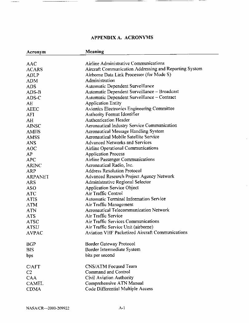
APPENDIX A. ACRONYMS
Acronym Meaning
AAC
ACARS
ADLP
ADM
ADS
ADS-B
ADS-C
AE
AEEC
AFI
AH
AINSC
AMHS
AMSS
ANS
AOC
AP
APC
ARINC
ARP
ARPANET
ARS
ASO
ATC
ATIS
ATM
ATN
ATS
ATSC
ATSU
AVPAC
BGP
BIS
bps
C/AFT
C2
CAA
CAMEL
CDMA
Airline Administrative Communications
Aircraft Communication Addressing and Reporting System
Airborne Data Link Processor (for Mode S)
Administration
Automatic Dependent Surveillance
Automatic Dependent Surveillance - Broadcast
Automatic Dependent Surveillance - Contract
Application Entity
Avionics Electronics Engineering Committee
Authority Format IdentifierAuthentication Header
Aeronautical Industry Service Communication
Aeronautical Message Handling SystemAeronautical Mobile Satellite Service
Advanced Networks and Services
Airline Operational Communications
Application Process
Airline Passenger Communications
Aeronautical Radio, Inc.
Address Resolution Protocol
Advanced Research Project Agency Network
Administrative Regional Selector
Application Service ObjectAir Traffic Control
Automatic Terminal Information Service
Air Traffic ManagementAeronautical Telecommunication Network
Air Traffic Service
Air Traffic Services Communications
Air Traffic Service Unit (airborne)
Aviation VHF Packetized Aircraft Communications
Border Gateway Protocol
Border Intermediate System
bits per second
CNS/ATM Focused Team
Command and Control
Civil Aviation Authority
Comprehensive ATN Manual
Code Differential Multiple Access
NASA/CR--2000-209922 A- 1

APPENDIX A. ACRONYMS
Acronym Meaning
CLNP
CLTP
CLTS
CM
CMA
CNS
COPP
COSP
COTS
CPDLC
CR/LF
CSNET
CU
DARPA
DATIS
DBS
DCA
DEL
DISA
DLIC
DLS
DM
DN
DSL
DSP
EACARS
ER
ES
ESP
FAA
FANS
FI
FIS
FIS-B
FMC
FMS
FP
FTP
Connectionless Network Protocol
Connectionless Transport Protocol
Connectionless Transport Service
Context Management
Context Management Application
Communications, Navigation, and SurveillanceConnection Oriented Presentation Protocol
Connection Oriented Session Protocol
Commercial-Off-The-Shelf
Controller Pilot Data Link Communication
Carriage Return/Line Feed
Computer Science NetworkControl Unit
Defense Advanced Research Projects Agency
Digital Automatic Terminal Information ServiceDirect Broadcast Satellite
Defense Communications Agency
Direct Exchange Loop
Defense Information Systems Agency
Data Link Initiation CapabilityData Link Services
Downlink MessageDown
Digital Subscriber Line
Domain Specific Part
Enhanced ACARS
Error Report
End System
Encapsulating Security Payload
Federal Aviation Administration
Future Air Navigation System
Flight Identifier
Flight Information Service
Flight Information Service - Broadcast
Flight Management Computer
Flight Management SystemFormat Prefix
File Transfer Protocol
NASA/CR--2000-209922 A-2

APPENDIX A. ACRONYMS
Acronym Meaning
GA
GEO
GPS
GRC
GUS
HF
IATA
ICAO
ICMP
IDI
IDP
IDRP
IETF
IFR
IGP
IGRP
IHL
IKE
IP
IPngIPsec
IPv4
IPv6
IS
ISN
ISO
ISP
IT
Kbps
LAAS
LOC
LSA
LSRR
MASPS
Mbps
General Aviation
Geostationary earth-orbit
Global Positioning System
Glenn Research Center
Ground Uplink System
High Frequency
International Air Transport Association
International Civil Aviation Organization
Internet Control Message Protocol
Initial Domain Identifier
Initial Domain Part
Inter-Domain Routing Protocol
Internet Engineering Task Force
Instrument Flight Rules
Interior Gateway Protocol
Interior Gateway Routing Protocol
Internet Header Length
Internet Key ExchangeInternet Protocol
Internet Protocol Next Generation
Internet Protocol Security
Internet Protocol version 4
Internet Protocol version 6
Intermediate System
Initial Sequence Number
International Organization for StandardizationInternet Service Provider
Information Technology
kilobits per second
Local Area Augmentation SystemLocation
Link-State Advertisement
Loose Source and Record Route
Minimum Aviation System Performance Standards
Megabits per second
NASA/CR--2000-209922 A-3

APPENDIX A. ACRONYMS
Acronym Meaning
METAR
MFI
MHz
MS
MU
NAS
NASA
NAT
NET
NEXRAD
NLA ID
NOR
NOTAM
NPDU
NSAP
NSDU
NSEL
NSF
NSFNET
OC
OCM
OOOI
OSI
OSPF
PBX
PC
PCI
PDC
PDU
PETAL
POTS
PPDU
PSAP
PSEL
PTT
QoS
International Aviation Routine Weather Report
Message Format Identifier
Megahertz
More Segments
Management Unit
National Airspace System
National Aviation and Space AdministrationNetwork Address Translation
Network Entity TitleNext Generation Radar
Next-Level Aggregation Identifier
No Orderly ReleaseNotice to Airmen
Network Protocol Data Unit
Network Service Access Point
Network Service Data Unit
Network Selector
National Science Foundation
National Science Foundation Network
Operation Concept
Oceanic Clearance MessageOut/Off/On/In
Open Systems Interconnection
Open Shortest Path First
Private Branch Exchange
Personal ComputerProtocol Control Information
Predeparture ClearanceProtocol Data Unit
Preliminary Eurocontrol Test of Air/ground data Link
Plain Old Telephone Service
Presentation Protocol Data Unit
Presentation Service Access Point
Presentation Selector
Public Telephone and Telegraph
Quality of Service
NASA/CR--2000-209922 A-4
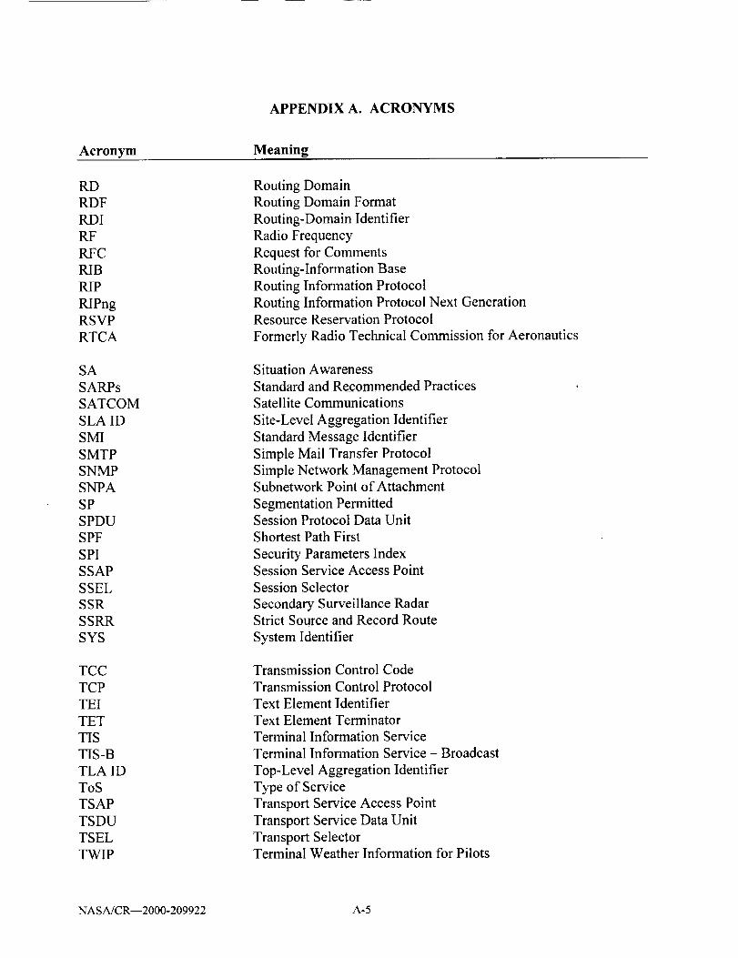
APPENDIX A. ACRONYMS
Acronym Meaning
RD
RDF
RDI
RF
RFC
RIB
RIP
RIPng
RSVP
RTCA
SA
SARPs
SATCOM
SLA ID
SMI
SMTP
SNMP
SNPA
SP
SPDU
SPF
SPI
SSAP
SSEL
SSR
SSRR
SYS
TCC
TCP
TEI
TET
TIS
TIS-B
TLA ID
ToS
TSAP
TSDU
TSEL
TWIP
Routing Domain
Routing Domain Format
Routing-Domain Identifier
Radio Frequency
Request for Comments
Routing-Information Base
Routing Information Protocol
Routing Information Protocol Next Generation
Resource Reservation Protocol
Formerly Radio Technical Commission for Aeronautics
Situation Awareness
Standard and Recommended Practices
Satellite Communications
Site-Level Aggregation Identifier
Standard Message Identifier
Simple Mail Transfer Protocol
Simple Network Management ProtocolSubnetwork Point of Attachment
Segmentation Permitted
Session Protocol Data Unit
Shortest Path First
Security Parameters IndexSession Service Access Point
Session Selector
Secondary Surveillance RadarStrict Source and Record Route
System Identifier
Transmission Control Code
Transmission Control Protocol
Text Element Identifier
Text Element Terminator
Terminal Information Service
Terminal Information Service - Broadcast
Top-Level Aggregation Identifier
Type of Service
Transport Service Access Point
Transport Service Data Unit
Transport SelectorTerminal Weather Information for Pilots
NASAJCR--2000-209922 A-5
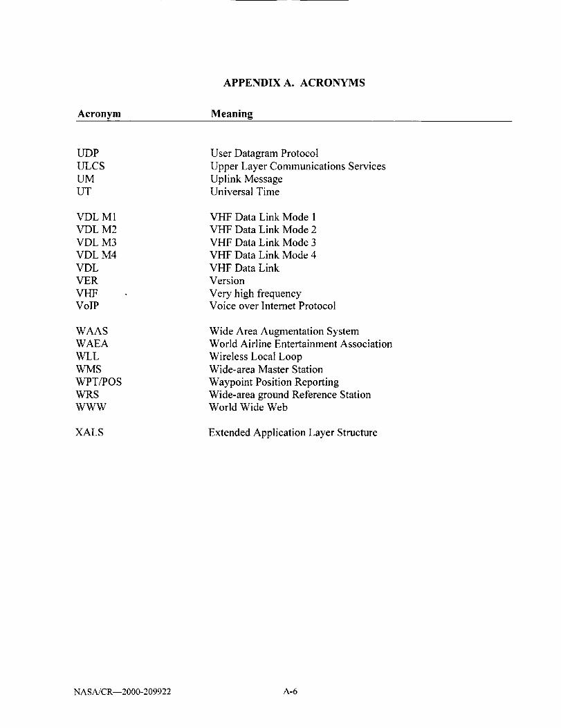
APPENDIX A. ACRONYMS
Acronym Meaning
L_P
ULCS
UM
LIT
User Datagram Protocol
Upper Layer Communications Services
Uplink MessageUniversal Time
VDL
VDL
VDL
VDL
VDL
VER
VHF
VolP
M1
M2
M3
M4
VHF Data Link Mode 1
VHF Data Link Mode 2
VHF Data Link Mode 3
VI-1F Data Link Mode 4
VHF Data Link
Version
Very high frequencyVoice over Intemet Protocol
WAAS
WAEA
WLL
WMS
WPT/POS
WRS
W-WW
Wide Area Augmentation SystemWorld Airline Entertainment Association
Wireless Local LoopWide-area Master Station
Waypoint Position Reporting
Wide-area ground Reference StationWorld Wide Web
XALS Extended Application Layer Structure
NASA/CR--2000-209922 A-6

APPENDIX B. CPDLC MESSAGES
Table B-1. CPDLC Uplink Messages
Dir
UM
UM
UM
UM
UM
UM
UM
UM
UM
UM
UM
UM
UM
UM
UM
UM
UM
UM
UM
UM
UM
UM
UM
UM
UM
UM
UM
UM
UM
Msg #
7
10
11
12
Message Title
UNABLE
STANDBY
REQUEST DEFERRED
ROGER Resp(N-)
AFFIRM Resp(N-)
NEGATIVE Resp(N-)
EXPECT [level]
EXPECT CLIMB AT [time]
EXPECT CLIMB AT [position]
EXPECT DESCENT AT [time]
EXPECT DESCENT AT [position]
EXPECT CRUISE CLIMB AT [time]
EXPECT CRUISE CLIMB AT [position]
13 AT [time] EXPECT CLIMB TO [level]
14 AT [position] EXPECT CLIMB TO [level]
15 AT [time] EXPECT DESCENT TO [level]
16 AT [position] EXPECT DESCENT TO [level]
17 AT [time] EXPECT CRUISE CLIMB TO [level]
18 AT [position] EXPECT CRUISE CLIMB TO [level]
19 MAINTAIN [level]
20 CLIMB TO [level]
21 AT [time] CLIMB TO [level]
22 AT [position] CLIMB TO [level]
23 DESCEND TO [level]
24 AT [time] DESCEND TO [level]
25 AT [position] DESCEND TO [level]
26 CLIMB TO REACH [level] BY [time]
27 CLIMB TO REACH [level] BY [position]
28 DESCEND TO REACH [level] BY [time]
NASA/CR--2000-209922 B- I

APPENDIX B. CPDLC MESSAGES
Table B-1. CPDLC Uplink Messages
Dir Msg #
UM 29
UM 30
UM 31
UM 32
UM 33
UM 34
UM 35
UM 36
UM 37
UM 38
UM 39
UM 40
UM 41
tiM 42
UM 43
UM 44
UM 45
UM 46
UM 47
UM 48
UM 49
UM 50
UM 51
UM 52
UM 53
UM 54
UM 55
UM 56
UM 57
Message Title
DESCEND TO REACH [level] BY [position]
MAINTAIN BLOCK [level] TO [level]
CLIMB TO AND MAINTAIN BLOCK [level] TO [level]
DESCEND TO AND MAINTAIN BLOCK [level] TO [level]
Reserved
CRUISE CLIMB TO [level]
CRUISE CLIMB ABOVE [level]
EXPEDITE CLIMB TO [level]
EXPEDITE DESCENT TO [level]
IMMEDIATELY CLIMB TO [level]
IMMEDIATELY DESCEND TO [level]
EXPECT TO CROSS [position] AT [level]
EXPECT TO CROSS [position] AT OR ABOVE [level]
Reserved
Reserved
EXPECT TO CROSS [position] AT OR BELOW [level]
EXPECT TO CROSS [position] AT AND MAINTAIN [level]
CROSS [position] AT [level]
CROSS [position] AT OR ABOVE [level]
CROSS [position] AT OR BELOW [level]
CROSS [position] AT AND MAINTAIN [level]
CROSS [position] BETWEEN [level] AND [level]
CROSS [position] AT [time]
CROSS [position] AT OR BEFORE [time]
CROSS [position] AT OR AFTER [time]
CROSS [position] BETWEEN [time] AND [time]
CROSS [position] AT [speed]
CROSS [position] AT OR LESS THAN [speed]
CROSS [position] AT OR GREATER THAN [speed]
NASA/CR--2000-209922 B-2

APPENDIX B. CPDLC MESSAGES
Table B-I. CPDLC Uplink Messages
Dir Msg # Message Title
UM 58 CROSS [position] AT [time] AT [level]
UM 59 CROSS [position] AT OR BEFORE [time] AT [level]
UM 60 CROSS [position] AT OR AFTER [time] AT [level]
UM 61 CROSS [position] AT AND MAINTAIN [level] AT [speed]
UM 62 AT [time] CROSS [position] AT AND MAINTAIN [level]
UM 63 AT [time] CROSS [position] AT AND MAINTAIN [level] AT [speed]
UM 64 OFFSET [specifiedDistance] [direction] OF ROUTE
UM 65 AT [position] OFFSET [specifiedDistance] [direction] OF ROUTE
UM 66 AT [time] OFFSET [specifiedDistance] [direction] OF ROUTE
UM 67 PROCEED BACK ON ROUTE
UM 68 REJOIN ROUTE BY [position]
UM 69 REJOIN ROUTE BY [time]
UM 70 EXPECT BACK ON ROUTE BY [position]
UM 71 EXPECT BACK ON ROUTE BY [time]
UM 72 RESUME OWN NAVIGATION
UM 73 [DepartureClearance]
UM 74 PROCEED DIRECT TO [position]
UM 75 WHEN ABLE PROCEED DIRECT TO [position]
UM 76 AT [time] PROCEED DIRECT TO [position]
UM 77 AT [position] PROCEED DIRECT TO [position]
UM 78 AT [level] PROCEED DIRECT TO [position]
UM 79 CLEARED TO [position] VIA [routeClearance]
UM 80 CLEARED [routeClearance]
UM 81 CLEARED [procedureName]
UM 82 CLEARED TO DEVIATE DN TO [specifiedDistance] [direction] OF ROUTE
UM 83 AT [position] CLEARED [routeCIearance]
UM 84 AT [position] CLEARED [procedureName]
UM 85 EXPECT [routeClearance]
UM 86 AT [position] EXPECT [routeClearance]
NASA/CR--2000-209922 B-3
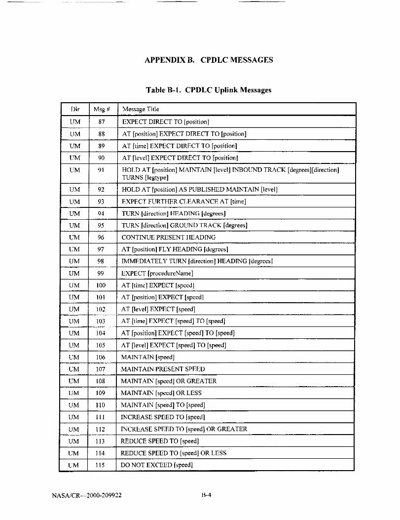
APPENDIX B. CPDLC MESSAGES
Table B-1. CPDLC Uplink Messages
Dir Msg # Message Title
UM 87 EXPECT DIRECT TO [position]
UM 88 AT [position] EXPECT DIRECT TO [position]
UM 89 AT [time] EXPECT DIRECT TO [position]
UM 90 AT [level] EXPECT DIRECT TO [position]
UM 91 HOLD AT [position] MAINTAIN [level] INBOUND TRACK [degrees] [direction]TURNS [legtype]
UM 92 HOLD AT [position] AS PUBLISHED MAINTAIN [level]
UM 93 EXPECT FURTHER CLEARANCE AT [time]
UM 94 TURN [direction] HEADING [degrees]
UM 95 TURN [direction] GROUND TRACK [degrees]
UM 96 CONTINUE PRESENT HEADING
UM 97 AT [position] FLY HEADING [degrees]
UM 98 IMMEDIATELY TURN [direction] HEADING [degrees]
UM 99 EXPECT [procedureName]
UM 100 AT [time] EXPECT [speed]
UM 101 AT [position] EXPECT [speed]
UM 102 AT [level] EXPECT [speed]
UM 103 AT [time] EXPECT [speed] TO [speed]
UM 104 AT [position] EXPECT [speed] TO [speed]
UM 105 AT [level] EXPECT [speed] TO [speed]
UM 106 MAINTAIN [speed]
UM 107 MAINTAIN PRESENT SPEED
UM 108 MAINTAIN [speed] OR GREATER
UM 109 MAINTAIN [speed] OR LESS
UM 110 MAINTAIN [speed] TO [speed]
UM 111 INCREASE SPEED TO [speed]
UM 112 INCREASE SPEED TO [speed] OR GREATER
UM 113 REDUCE SPEED TO [speed]
UM 114 REDUCE SPEED TO [speed] OR LESS
UM 115 DO NOT EXCEED [speed]
NASA/CR--2000-209922 B-4

APPENDIX B. CPDLC MESSAGES
Table B-1. CPDLC Uplink Messages
Dir
UM
UM
UM
UM
UM
UM
UM
UM
UM
UM
UM
UM
L_Vl
UM
UM
UM
Msg #
116
117
118
119
120
121
122
i23
124
125
126
127
128
129
130
131
Message Title
RESUME NORMAL SPEED
CONTACT [unitname] [frequency]
AT [position] CONTACT [unitname] [frequency]
AT [time] CONTACT [unitname] [frequency]
MONITOR [unitname] [frequency]
AT [position] MONITOR [unitname] [frequency]
AT [time] MONITOR [unimame] [frequency]
SQUAWK [code]
STOP SQUAWK
SQUAWK MODE CHARLIE
STOP SQUAWK MODE CHARLIE
REPORT BACK ON ROUTE
REPORT LEAVING [level]
REPORT MAINTAINING [level]
REPORT PASSING [position]
REPORT REMAINING FUEL AND PERSONS ON BOARD
UM 132 REPORT POSITION
UM 133 REPORT PRESENT LEVEL
UM 134 REPORT [speedtype] [speedtype] [speedtype]SPEED
UM 135 CONFIRM ASSIGNED LEVEL
UM 136 CONFIRM ASSIGNED SPEED
UM 137 CONFIRM ASSIGNED RO_ __
UM 138 CONFIRM TIME OVER REPORTED WAYPOINT
UM 139 CONFIRM REPORTED WAYPOINT
UM 140 CONFIRM NEXT WAYPOINT
UM 141 CONFIRM NEXT WAYPOINT ETA
UM 142 CONFIRM ENSUING WAYPOINT
UM 143 CONFIRM REQUEST
UM 144 CONFIRM SQUAWK
NASA/CR--2000-209922 B- 5
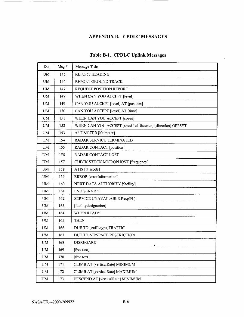
APPENDIX B. CPDLC MESSAGES
Table B-1. CPDLC Uplink Messages
Dir Msg # Message Title
UM 145 REPORT HEADING
UM 146 REPORT GROUND TRACK
UM 147 REQUEST POSITION REPORT
UM 148 WHEN CAN YOU ACCEPT [level]
UM 149 CAN YOU ACCEPT [level] AT [position]
UM 150 CAN YOU ACCEPT [level] AT [time]
UM 151 WHEN CAN YOU ACCEPT [speed]
UM 152 WHEN CAN YOU ACCEPT [specifiedDistance] [direction] OFFSET
UM 153 ALTIMETER [altimeter]
I.YM 154 RADAR SERVICE TERMINATED
UM 155 RADAR CONTACT [position]
UM 156 RADAR CONTACT LOST
UM 157 CHECK STUCK MICROPHONE [frequency]
UM 158 ATIS [atiscode]
UM 159 ERROR [errorlnformation]
UM 160 NEXT DATA AUTHORITY [facility]
UM 161 END SERVICE
UM 162 SERVICE UNAVAILABLE Resp(N )
UM 163 [facilitydesignation]
UM 164 WHEN READY
UM 165 THEN
UM 166 DUE TO [traffictype]TRAFFlC
UM 167 DUE TO AIRSPACE RESTRICTION
UM 168 DISREGARD
UM 169 [free text]
UM 170 [free text]
UM 171 CLIMB AT [verticalRate] MINIMUM
UM 172 CLIMB AT [verticalRate] MAXIMUM
UM 173 DESCEND AT [verticalRate] MINIMUM
NASA/CR--2000-209922 B-6

APPENDIX B. CPDLC MESSAGES
Table B-1. CPDLC Uplink Messages
Dir
UM
UM
UM
UM
UM
UM
UM
UM
UM
UM
UM
UM
UM
UM
UM
UM
UM
UM
UM
UM
UM
UM
UM
UM
UM
UM
UM
UM
Msg #
174
175
176
177
178
179
180
181
182
183
184
185
186
187
188
189
190
191
192
193
194
195
196
197
198
199
200
201
202
Message Title
DESCEND AT [verticalRate] MAXIMUM
REPORT REACHING [level]
MAINTAIN OWN SEPARATION AND VMC
AT PILOTS DISCRETION
Reserved
SQUAWK IDENT
REPORT REACHING BLOCK [level] TO [level]
REPORT DISTANCE [tofrom] [position]
CONFIRM ATIS CODE
[flee text]
AT [time] REPORT DISTANCE [tofrom] [position]
AFTER PASSING [position] CLIMB TO [level]
AFTER PASSING [position] DESCEND TO [level]
[flee text]
AFTER PASSING [position] MAINTAIN [speed]
ADJUST SPEED TO [speed]
FLY HEADING [degrees]
ALL ATS TERMINATED
REACH [level] BY [time]
IDENTIFICATION LOST
[flee text]
[flee text]
[flee text]
[free text]
[free text]
[flee text]
REPORTREACHING
Not Used
Not Used
NASA/CR--2000-209922 B-7
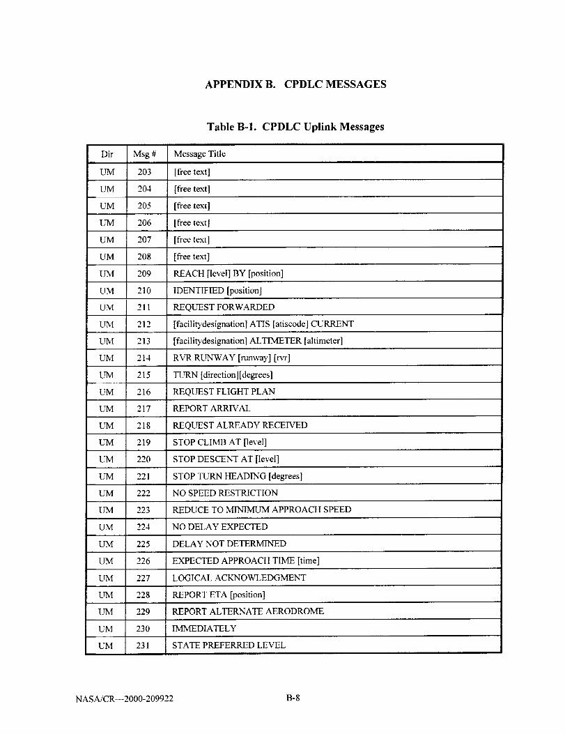
APPENDIX B. CPDLC MESSAGES
Table B-1. CPDLC Uplink Messages
Dirimmm
UM
UM
UM
UM
Msg #
203
204
205
206
207
208
209
210
211
212
213
214
215
216
217
218
219
220
221
222
223
224
225
226
227
228
229
UM 230
UM 231
Message Title
[flee text]
[flee text]
[flee text]
[free text]
[flee text]
[flee text]
REACH [level] BY [position]
IDENTIFIED [position]
REQUEST FORWARDED
[facilitydesignation] ATIS [atiscode] CURRENT
[facilitydesignation] ALTIMETER [altimeter]
RVR RUNWAY [runway] [rvr]
TURN [direction] [degrees]
REQUEST FLIGHT PLAN
REPORT ARRIVAL
REQUEST ALREADY RECEIVED
STOP CLIMB AT [level]
STOP DESCENT AT [level]
STOP TURN HEADING [degrees]
NO SPEED RESTRICTION
REDUCE TO MINIMUM APPROACH SPEED
NO DELAY EXPECTED
DELAY NOT DETERMINED
EXPECTED APPROACH TIME [time]
LOGICAL ACKNOWLEDGMENT
REPORT ETA [position]
REPORT ALTERNATE AERODROME
IMMEDIATELY
STATE PREFERRED LEVEL
NASA/CR--2000-209922 B-8

APPENDIX B. CPDLC MESSAGES
Table B-1. CPDLC Uplink Messages
Dir
UM
UM
UM
UM
UM
Msg # Message Title
232 STATE-TOP-OF-DESCENT
233 USE OF LOGICAL ACKNOWLEDGMENT PROHIBITED
234 FLIGHT PLAN NOT HELD
235 ROGER 7500
236 LEAVE CONTROLLED AIRSPACE
NASA/CR--2000-209922 B-9

APPENDIX B. CPDLC MESSAGES
Table B-2. CPDLC Downlink Messages
Dir Msg # Message Title
DM 0 WILCO
DM 1 UNABLE
DM 2 STANDBY
DM 3 ROGER
DM 4 AFFIRM
DM 5 NEGATIVE
DM 6 REQUEST [level]
DM 7 REQUEST BLOCK [level] TO [level]
DM 8 REQUEST CRUISE CLIMB TO [level]
DM 9 REQUEST CLIMB TO [level]
DM 10 REQUEST DESCENT TO [level]
DM 11 AT [position] REQUEST CLIMB TO [level]
DM 12 AT [position] REQUEST DESCENT TO [level]
DM 13 AT [time] REQUEST CLIMB TO [level]
DM 14 AT [time] REQUEST DESCENT TO [level]
DM 15 REQUEST OFFSET [specifiedDistance] [direction] OF ROUTE
DM 16 AT [position] REQLrEST OFFSET [specifiedDistance] [direction] OF ROUTE
DM 17 AT [time] REQUEST OFFSET [specifiedDistance] [direction] OF ROUTE
DM 18 REQUEST [speed]
DM 19 REQUEST [speed] TO [speed]
DM 20 REQUEST VOICE CONTACT
DM 2 ! REQUEST VOICE CONTACT [frequency]
DM 22 REQUEST DIRECT TO [position]
DM 23 REQUEST [procedureName]i
DM 24 REQUEST [routeClearance]
DM 25 REQUEST [clearanceType] CLEARANCE
DM 26 REQUEST WEATHER DEVIATION TO [position] VIA [routeClearance]
DM 27 REQUEST WEATHER DEVIATION UP TO [specifiedDistance] [direction] OFROUTE
DM 28 LEAVING [level]
NASA/CR--2000- 209922 B- 10
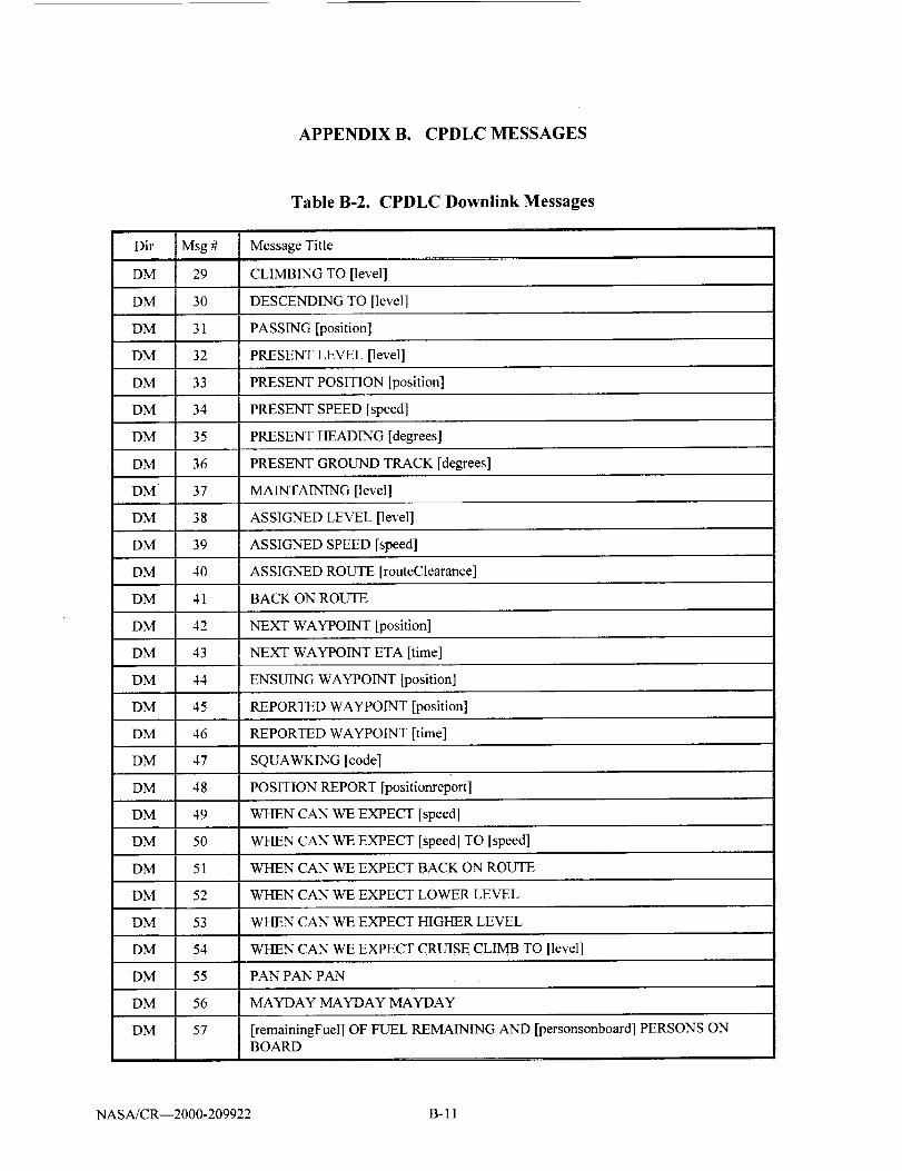
APPENDIX B. CPDLC MESSAGES
Table B-2. CPDLC Downlink Messages
Dir Msg # Message Title
DM 29 CLIMBING TO [level]
DM 30 DESCENDING TO [level]
DM 31 PASSING [position]
DM 32 PRESENT LEVEL [level]
DM 33 PRESENT POSITION [position]
DM 34 PRESENT SPEED [speed]
DM 35 PRESENT HEADING [degrees]
DM 36 PRESENT GROUND TRACK [degrees]
DM 37 MAINTAINING [level]
DM 38 ASSIGNED LEVEL [level]
DM 39 ASSIGNED SPEED [speed]
DM 40 ASSIGNED ROUTE [routeClearance]
DM 41 BACK ON ROUTE
DM 42 NEXT WAYPOINT [position]
DM 43 NEXT WAYPOINT ETA [time]
DM 44 ENSUING WAYPOINT [position]
DM 45 REPORTED WAYPOINT [position]
DM 46 REPORTED WAYPOINT [time]
DM 47 SQUAWKING [code]
DM 48 POSITION REPORT [positiortreport]
DM 49 WHEN CAN WE EXPECT [speed]
DM 50 WHEN CAN WE EXPECT [speed] TO [speed]
DM 51 WHEN CAN WE EXPECT BACK ON ROUTE
DM 52 WHEN CAN WE EXPECT LOWER LEVEL
DM 53 WHEN CAN WE EXPECT HIGHER LEVEL
DM 54 WHEN CAN WE EXPECT CRUISE CLIMB TO [level]
DM 55 PAN PAN PAN
DM 56 MAYDAY MAYDAY MAYDAY
DM 57 [remainingFuel] OF FUEL REMAINING AND [personsonboard] PERSONS ONBOARD
NASA/CR--2000-209922 B- 11

APPENDIX B. CPDLC MESSAGES
Table B-2. CPDLC Downlink Messages
Dir Msg #
DM 58
DM 59
DM 60
DM 61
DM 62
DM 63
DM 64
DM 65
DM 66
DM 67
DM 68
DM 69
DM 70
DM 71
DM 72
DM 73
DM 74
DM 75
DM 76
DM 77
DM 78
DM 79
DM 80
DM 81
DM 82
DM 83
DM 84
DM 85
DM 86
Message Title
CANCEL EMERGENCY
DIVERTING TO [position] VIA [routeClearance]
OFFSETTING [specifiedDistance] [direction] OF ROUTE
DESCENDING TO [level]
ERROR [errorlnformation]
NOT CURRENT DATA AUTHORITY
[facilibdesignation]
DUE TO WEATHER
DUE TO AIRCRAFT PERFORMANCE
[free text]
[free text]
REQUEST VMC DESCENT
REQUEST HEADING [degrees]
REQUEST GROUND TRACK [degrees]
REACHING [level]
[versionnumber]
REQUEST TO MAINTAIN OWN SEPARATION AND VMC
AT PILOTS DISCRETION
REACHING BLOCK [level] TO [level]
ASSIGNED BLOCK [level] TO [level]
AT [time] [distance] [tofrom] [position]
ATIS [atiscode]
DEVIATING UP TO [specifiedDistance] [direction] OF ROUTE
WE CAN ACCEPT [level] AT [time]
WE CANNOT ACCEPT [level]
WE CAN ACCEPT [speed] AT [time]
WE CANNOT ACCEPT [speed]
WE CAN ACCEPT [specifiedDistance] [direction] AT [time]
WE CANNOT ACCEPT [specifiedDistance] [direction]
NASA/CR--2000-209922 B- 12

APPENDIX B. CPDLC MESSAGES
Dir Msg #
DM 87
DM 88
DM 89
DM 90
DM 91
DM 92
DM 93
DM 94
DM 95
DM 96
DM 97
DM 98
DM 99
DM 100
DM 101
DM 102
DM 103
DM 104
DM 105
DM 106
DM 107
DM 108
DM 109
DM 1I0
DM 111
DM 1I2
DM 113
Table B-2. CPDLC Downlink Messages
Message Title
WHEN CAN WE EXPECT CLIMB TO [level]
WHEN CAN WE EXPECT DESCENT TO [level]
MONITORING [unitname] [frequency]
[flee text]
[flee text]
[flee text]
[flee text]
[flee text]
[flee text]
[flee text]
[flee text]
[flee text]
CURRENT DATA AUTHORITY
LOGICAL ACKNOWLEDGMENT
REQUEST END OF SERVICE
LANDING REPORT
CANCELING IFR
ETA[positionl[time]
ALTERNATE AERODROME[airport]
PREFERRED LEVEL[level]
NOT AUTHORIZED NEXT DATA AUTHORITY
DE-ICING COMPLETE
TOP OF DESCENT [time]
TOP OF DESCENT [position]
TOP OF DESCENT [time] [position]
SQUAWKING 7500
[speedType] [speedType] [speedType] SPEED [speed]
NASA/CR--2000-209922 B- 13
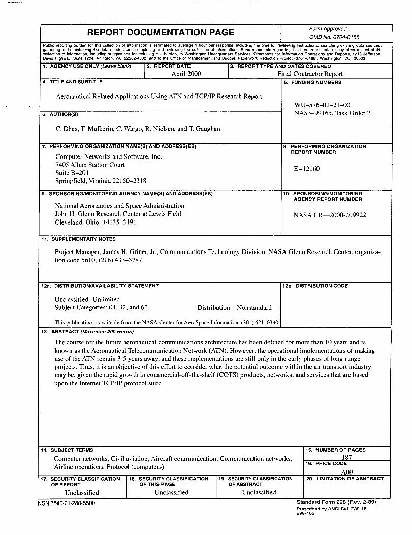
REPORT DOCUMENTATION PAGE I FormApprovedOMB No. 0704-0188
Public reporting burden for this collection of information is estimated to average 1 hour per response, including the time for reviewing instructions, searching existing data sources,
gathering and maintaining the data needed, and completing and reviewing the collection of information. Send comments regarding this burden estimate or any other aspect of this
collection of information, including suggestions for reducing this burden, to Washington Headquarters Services, Directorate for Information Operations and Reports, 1215 Jefferson
Davis Highway, Suite 1204, Arlington, VA 22202-4302, and to the Office of Management and Budget, Paperwork Reduction Project (0704-0188), Washington, DC 20503.
1. AGENCY USE ONLY (Leave blank) 2. REPORT DATE 3. REPORT TYPE AND DATES COVERED
April 2000 Final Contractor Report
4. TITLE AND SUBTITLE 5. FUNDING NUMBERS
Aeronautical Related Applications Using ATN and TCP/IP Research Report
6. AUTHOR(S)
C. Dhas, T. Mulkerin, C. Wargo, R. Nielsen, and T. Gaughan
, , r
7. PERFORMING ORGANIZATION NAME(S) AND ADDRESS(kS)
Computer Networks and Software, Inc.
7405 Alban Station Court
Suite B-201
Springfield, Virginia 22150-2318
9. SPONSORING/MONITORING AGENCY NAME(S) AND ADDRESS(kS)
National Aeronautics and Space Administration
John H. Glenn Research Center at Lewis Field
Cleveland, Ohio 44135-3191
11. SUPPLEMENTARY NOTES
WU-576-01-21--00
NAS3-99165, Task Order 2
8. PERFORMING ORGANIZATIONREPORT NUMBER
E-12160
10. SPONSORING/MONITORINGAGENCY REPORT NUMBER
NASA CR--2000-209922
Project Manager, James H. Griner, Jr., Communications Technology Division, NASA Glenn Research Center, organiza-
tion code 5610, (216) 433-5787.
12a. DISTRIBUTION/AVAILABILITY STATEMENT
Unclassified - Unlimited
Subject Categories: 04, 32, and 62 Distribution: Nonstandard
This publication is available from the NASA Center for AeroSpace Information, (301) 621_)390.
12b. DISTRIBUTION CODE
] 13. ABSTRACT (Maximum 200 words)
The course for the future aeronautical communications architecture has been defined for more than l0 years and is
known as the Aeronautical Telecommunication Network (ATN). However, the operational implementations of making
use of the ATN remain 3-5 years away, and these implementations are still only in the early phases of long-range
projects. Thus, it is an objective of this effort to consider what the potential outcome within the air transport industry
may be, given the rapid growth in commercial-off-the-shelf (COTS) products, networks, and services that are based
upon the Internet TCP/IP protocol suite.
14. SUBJECT TERMS
Computer networks; Civil aviation; Aircraft communication; Communication networks;
Airline operations; Protocol (computers)
17. SECURITY CLASSIFICATION 18. SECURITY CLASSIFICATIONOF REPORT OF THIS PAGE
Unclassified Unclassified
NSN 7540-01-280-5500
19. SECURITY CLASSIRCATIONOF ABSTRACT
Unclassified
15. NUMBER OF PAGES
1_716. PRICE CODE
AQ920. LIMITATION OF ABSTRACT
Standard Form 298 (Rev. 2-89)Preso-iloedby ANSI Std. Z39-18298-102