aesculap spine activ l - precisionsurgical.com.au · d.1.3 parallel distraction, ... this...
TRANSCRIPT

Aesculap Spineactiv L®
Lumbar Intervertebral Disc Prosthesis
Operating technique

2
activ L®

3
Contents
A) Product Information
A.1 Product Features 4
A.2 Safety Information 5
A.3 Sterility 5
B) Pre-Operative Planning
B.1 Size Estimation 6
B.2 Patient Positioning 6
C) Approach
C.1 Marking the Approach 7
C.2 Skin Incision 7
C.3 Approach 8
C.4 Anatomical Structures 9
C.5 Spike Version vs. Keel Version 12
C.6 S1 Inferior Plate 13
D1) Instrumentation – Spike Version
D.1.1 Midline Marking 14
D.1.2 Discectomy and Segment Mobilization 16
D.1.3 Parallel Distraction, Height Measurement and Size Verification 18
D.1.4 En Bloc Implantation 20
D2) Instrumentation – Keel Version
D.2.1 Chisels for Keel Fixation 26
E) Correction of Implant Position and Inlay Revision
E.1 Correction of Implant Position 30
E.2 Inlay Revision 33
F1) Implant Overview 34
F2) Instrument Overview 35

A) Product Information
4
Less risk of over-distraction.Use also possible in low disc space cases:Numerous surgeons started to use activ L®
because of the low minimum height of the implant, which gives the option to treat patients without overdistraction even if thedisc space is very small.
Spike version provides the option of intra-operative correction:Insertion of the spike version is suitabel forboth, the anterior and the anterolateral appro-ach.The spike version allows an intraoperative correction in the lateral, the anterior-posteriorand rotational direction.
Primary stability of spike version is com-parable (slightly better) to keel version:Biomechanical tests show that the spike version has higher pull-out strength in anterior-posterior direction then the keel version.
Push-Out-Load in N of activ L® Spike Versionand Prodisc (Keel Version)
In a Push-Out-Load test activ L® Spike Versionshowed a significantly higher push-out resistance versus Prodisc L with keels on bothsides.
8.5 mm
Clinical results show, that in approx 47.5 % the applicationof a small height (less then 9 mm) is indicated.
A.1 Product Features
0
200
400
600
800
1000
1200
1400
(N) Push-Out-Load (N)
activ L® Spikes Prodisc
Fmean=
1260 N
Fmean=
938 N
+/- 65 N
+/- 22 N

5
A.2 Safety Information
Under no circumstances may modular implantcomponents from different suppliers be combined.Previously implanted devices may not be reused.Damage to the load-bearing structures of the implant may cause the loosening of com-ponents, their dislocation and migration, andother severe complications.Postoperatively, the implant should be in-spected on a regular basis to determine whether it is functioning properly.
The implant components are provided in pro-tective packaging that is labeled to indicate its contents.The implant components are provided sterile.Implant components may not be resterilized.Components are to be kept in their originalpackaging until just prior to use.Prior to use, check the expiration date and assure the integrity of the packaging. Do not use components if they are past theirexpiration date or if the packaging has beendamaged.
A.3 Sterility

B) Pre-Operative Planning
6
B.1 Size Estimation
Assess the largest possible implant bed areausing ct-scan diagnostics with x-ray templatesand check the scale factor of the used template.
Control the anatomy of the major vessels,especially the left common iliac vein. Is it possible to mobilize the vessels sufficientlyand to move them away from your approach? Would a pararectus approach be easier?
B.2 Patient Positioning
The operating table should permit image intensifier images in 2 planes in the operatingzone.
Place the patient in a supine position withslightly flexed hips to relieve tension from the major blood vessels.
If the operating table permits a spread leg position, this facilitates axially correct im-plantation of the prosthesis.
Alternatively, the patient is positioned withboth legs together. In this case the surgeonstands on the approach side of the patient. A right side approach is recommended for theL5/S1 level and a left side approach for higherlevels.
Warning:m There is a risk of selecting the wrong size of the prosthesis plate
if an X-ray template with wrong scale is used. m Be sure to use an X-ray template of the correct scale.m Preoperative planning using X-ray templates is required.
Warning:m There is an increased risk of migration if the prosthesis plate se-
lected is too small. The plate must completely cover the end of the vertebral body. Select a prosthesis plate that provides maxi-mum coverage of the vertebral body.
Warning:m Select the correct inlay height to achieve height reconstruction
whilst preserving adequate mobility in the joint.
7
C.1 Marking the Approach
C) Approach
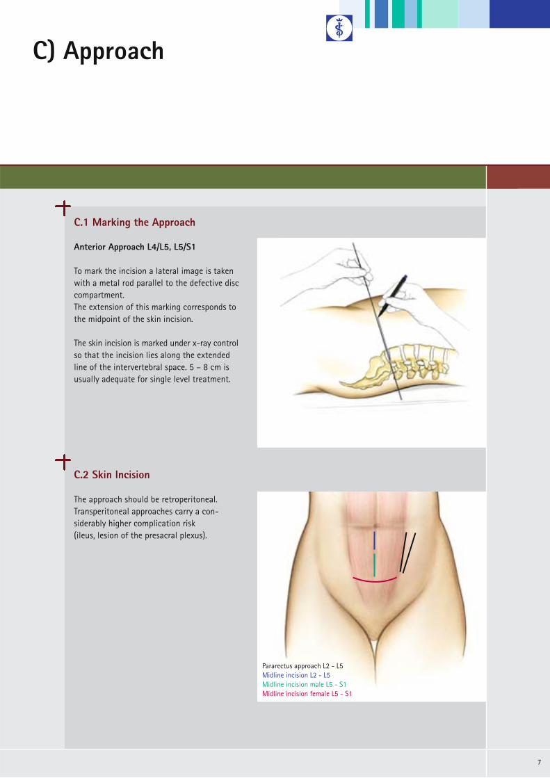
Anterior Approach L4/L5, L5/S1
To mark the incision a lateral image is takenwith a metal rod parallel to the defective disccompartment. The extension of this marking corresponds tothe midpoint of the skin incision.
The skin incision is marked under x-ray controlso that the incision lies along the extended line of the intervertebral space. 5 – 8 cm isusually adequate for single level treatment.
C.2 Skin Incision
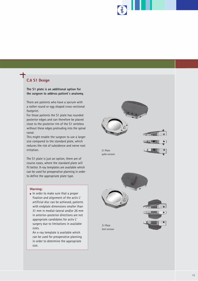
The approach should be retroperitoneal.Transperitoneal approaches carry a con-siderably higher complication risk (ileus, lesion of the presacral plexus).
Pararectus approach L2 - L5Midline incision L2 - L5Midline incision male L5 - S1Midline incision female L5 - S1

C) Approach
8
Midline Approach L5/S1
A midline approach is always used for theL5/S1 level.
A Pfannenstiel´s incision or a linear midline incision are possible.
Both sides are possible for the approach. If no other level is to be operated on, theright side may be preferred.
C.3 Approach
Pararectus Approach L3/4, L4/5
A midline approach or a pararectus approach (always left) are possible in the L3/4 and L4/5 segments.
Note:Advantages of the midline approach:m Considerably easier implant positioning, less retraction
of the abdominal muscles required.
Note:Advantages of the pararectus approach: m Simpler retroperitoneal preparation, less manipulation
of the vessels in L4/5.
NB:m All approaches demand the greatest care in the preparation of the major vessels.m A vascular surgeon should be constantly available on call during this operation.

9
C.4 Anatomical structures
Midline + Pararectus Approach L5/S1 + L3/4, L4/5
Anterior transperitoneal
Anterior retroperitoneal
Antero-lateral retroperitoneal
Antero-lateral transmucular

C) Approach
10
Midline Approach L5/S1
After the skin incision: linear incision of theanterior fascia of the rectus abdominis muscle a few millimeters paramedially. A blunt instrument is used to push the peri-toneum away in a medial direction, first fromthe rear surface of the muscle and then fromthe lateral abdominal wall.
Epigastric blood vessels must be coagulatedand dissected if necessary.
Pararectus Approach L3/4, L4/5
Midline Approach:As described for ventral L5/S1. The essential difference from the L5/S1 level is that the rectus abdominis muscle in thecentral and upper abdomen also possesses arear fascia which it does not have in the lowerabdomen. Since this can only be removed fromthe peritoneum with great difficulty, it shouldbe opened as far laterally as possible afterretraction of the muscle.
Pararectus Approach:Considerably easier on the upper lumbar regionof the spine, but only suitable for the spikeversion. Higher risk of segmental denervationof the abdominal muscles.
The muscle fascia is dissected longitudinallywhere it meets at the lateral margin of therectus abdominis muscle.
C.4 Anatomical Structures

11
Pararectus Approach L3/4, L4/5
A blunt instrument is used to push the peri-toneum away from the abdominal wall whilstmonitoring the epigastric vessels. The ureter is prepared away from the operatingsite together with the peritoneum. The ventrolateral spine is exposed at the anterior margin of the psoas muscle.The neighbouring segment vessels are ligatedand dissected, including the ascending lumbarvein for the approach to the L4/5 segment, sothat the major vessels can be mobilized to theopposite side.The sympathetic nerve is mobilized in a lateraldirection. If possible the situs is “fixed” withself-retaining retractors.
Note:m In the midline marking process, the lateral in-
clination of the operating table may have to be adjusted to compensate for any possible turning of the patient caused by retraction of the muscles and abdominal organs.
m Small errors in the axial orientation of the control x-ray can lead to serious malpositioningof the implant.
Midline Approach L5/S1
The ureter and the presacral plexus are care-fully mobilized and retracted together with the peritoneum (coagulation should be avoided).The medial sacral vessels are ligated and dis-sected in the bifurcation of the major vessels. The vessels are mobilized as far to the left as isnecessary (or possible) to facilitate implantationof the planned prosthesis size.
NB:m The linea alba is not opened. The anterior fascia
of the rectus is opened paramedially.

C) Approach
12
C.5 Spike Version vs. Keel Version
Generally the use of the spike version is indicated.
Biomechanical tests show that the spike version shows comparable pull-out strength in anterior-posterior direction then the keelversion. This is due to the convex shape of the upper plate and the resistance of the three spikes compared to the resistance of only one keel. The spike version allows an intraoperative correction in both the lateral and anterior-posterior direction.There is less damage to the vertebral end-plates with the spike compared to the keelversion. Therefore less risk for migration of the prothesis into the vertebral body and lessrisk of fusion due to the bleeding caused bychiseling.The chiseling puts a lot of force into the whole structure and therefore could lead to a injury of the vertebral segment.
The keel version is indicated if the endplatesshow an extreme concave curve or extremeunevenness of the surface. The keel version is not indicated if the vertebralendplates show a strong sclerotiziation. In this case there is a high risk to injure thevertebral structure or to split the vertebral body due to the high forces necessary for chiseling and impacting the implant.
activ L®
spike version
activ L®
keel version
13
C.6 S1 Design
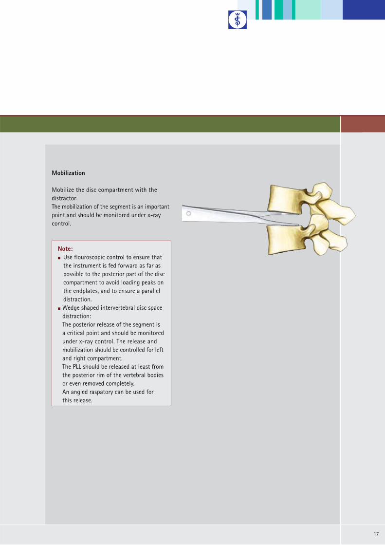
The S1 plate is an additional option forthe surgeon to address patient`s anatomy.
There are patients who have a sacrum with a rather round or egg shaped cross-sectionalfootprint. For those patients the S1 plate has rounded posterior edges and can therefore be placedclose to the posterior rim of the S1 vertebrawithout these edges protruding into the spinalcanal. This might enable the surgeon to use a largersize compared to the standard plate, which reduces the risk of subsidence and nerve rootirritation.
The S1 plate is just an option, there are ofcourse cases, where the standard plate will fit better. X-ray templates are available whichcan be used for preoperative planning in orderto define the appropriate plate type.
Warning:m In order to make sure that a proper
fixation and alignment of the activ L®
artificial disc can be achieved, patients with endplate dimensions smaller than 31 mm in medial-lateral and/or 26 mm in anterior-posterior directions are not appropriate candidates for activ L®
surgery due to limitations in available sizes. An x-ray template is available which can be used for preoperative planning in order to determine the appropriate size.
S1 Platespike version
S1 Platekeel version

D1) Instrumentation – Spike Version
14
Midline Approach L5/S1
Define the midline of the vertebral body underap x-ray control.
Pararectus Approach* L3/4, L4/5
The midline marker must be selected accordingto the preplanned implant size S, M, L or XL.
D.1.1 Midline Marking
activ L®
spike version
ap projection
* Pararectus ApproachThe pararectus approach is only explicitly described when the instruments or technique differ from those of the midline approach. Otherwise the midline approach is given as an example.

15
Pararectus Approach L3/4, L4/5
Define the 45° approach to the vertebral bodywith the help of the lateral midline marker un-der ap and lateral x-ray control.
First an ap x-ray is done to check the midlineposition of the marker. If the ap-midline iscorrect a lateral x-ray is done. Also in this view the Tantalum Marker of thedevice must be targeted to the lateral midlineof the vertebral body. If the size selected doesnot fit, choose a different marker size.Mark the 45° position with the pin in the disccompartment.
Midline Approach L5/S1
The midline is marked with the pin in the disc compartment under image intensifiercontrol.Alternatively, the marking can be set in theneighbouring vertebral body for the entire duration of the surgery. Applicable only / mainly for the spike version.
ap projection
lateral projection
NB:m Make sure that the vertebrae are portrayed in an orthograde position on the x-ray. The pedicles and the spinous
process can be used for orientation and determination of the midline.m The exact position of the implant is of vital importance for correct function.

D1) Instrumentation – Spike Version
16
D.1.2 Discectomy and Mobilization of the Segment
Discectomy
A discectomy is performed and the endplatescleansed from disc residue with a curette. The cartilage is also removed to facilitate osteointegration of the Plasmapore® µ-CaP coating of the implant endplates.
If necessary, metal wedges available in differentheights or the angled distractor can be used tomaintain the correct distance.
The angled distractor provides a better viewinto the operating site and facilitates the discectomy and preparation of endplates.
NB:m The cartilage structures should be re-
moved as completely as possible. Cartilage structures can impede osteo-integration of the Plasmapore® µ-CaP coating of the implant endplates.
m Extensive preparation of the endplates could increase the risk of implant migration.
m The lateral preparation of the anulus should be adjusted to the extend of re-quired mobilization and the needed space for the activ L® prosthesis, which can be assessed with the trial implants.
17
Mobilization
Mobilize the disc compartment with the distractor. The mobilization of the segment is an importantpoint and should be monitored under x-raycontrol.
Note:m Use flouroscopic control to ensure that
the instrument is fed forward as far as possible to the posterior part of the disccompartment to avoid loading peaks on the endplates, and to ensure a paralleldistraction.
m Wedge shaped intervertebral disc space distraction:The posterior release of the segment is a critical point and should be monitored under x-ray control. The release and mobilization should be controlled for left and right compartment.The PLL should be released at least from the posterior rim of the vertebral bodiesor even removed completely.An angled raspatory can be used for this release.

D1) Instrumentation – Spike Version
18
D.1.3 Parallel Distraction, Height Measurement and Size Verification
Mount the trial implant with the defined angleand size onto the parallel distractor.
Align the midline markings on the trial implantand the instrument.
Verify the size of the trial implant in the disccompartment by x-ray.Expand the parallel distractor by turning therear button until the resistance due to dis-traction increases (sufficient distraction isachieved when the button can not be turnedeasily by hand anymore). Check carefully the position and placement ofthe implant by x-ray. If necessary try a differentsize of trial implant.
NB:m If the loading is too high, the parallel
distractor can be bended. In this case the scale will show the wrong height (too high). Please choose a smaller height for implantation. Please check during the whole size verification the parallel alignment of the two trial endplates with x-ray control.

19
Midline Approach L5/S1
For the midline approach the trial implant ismounted in 0° position.
Pararectus Approach L3/4, L4/5
Align the side markings of the trial implantand the instrument. Mount the trial implant in a 22.5° position.
The angle of the parallel distractor (22.5°) is half that of the inserter (45°) in order to make it easier for frequent insertions.

D1) Instrumentation – Spike Version
20
D.1.3 Parallel Distraction, Height Measurement and Size Verification
Read the height on the scale. If the indicatorlies between two numbers, choose the smallerheight.
Release and remove the parallel distractor.Position “R” for “Release” for disassembly.
If necessary use the spacer of the appropriateheight to maintain the correct distance afterremoval of the parallel distractor.
Note:m The footprint of the implant should cover
most of the vertebral endplates. Too small implants increase the risk of migration into the endplates.
m An oversized inlay may lead to over-distraction, which can irritate the facets, (dura) or nerves.
m An undersized inlay could mean that the implant sits too loosely in the degenerateddisc compartment which could lead to instability.

21
Slide the inlay into the inferior plate with the notch towards the posterior part of theprosthesis.
Select the inserter that corresponds to theheight of the inlay. The inserter spacers are colour coded: 8.5 mm: blue 10 mm: green 12 mm: black14 mm: yellow
Turn the rear button to move the spacer (fork) forward. The spacer ensures that the implant is introduced in a neutral position.
Turn the button to the right to move the spacer forward. Turn the button to the left to move the spacer backward.
D.1.4 En Bloc Implantation
Turn lock to the right to mountthe implant.
Fork for neutral implantposition.
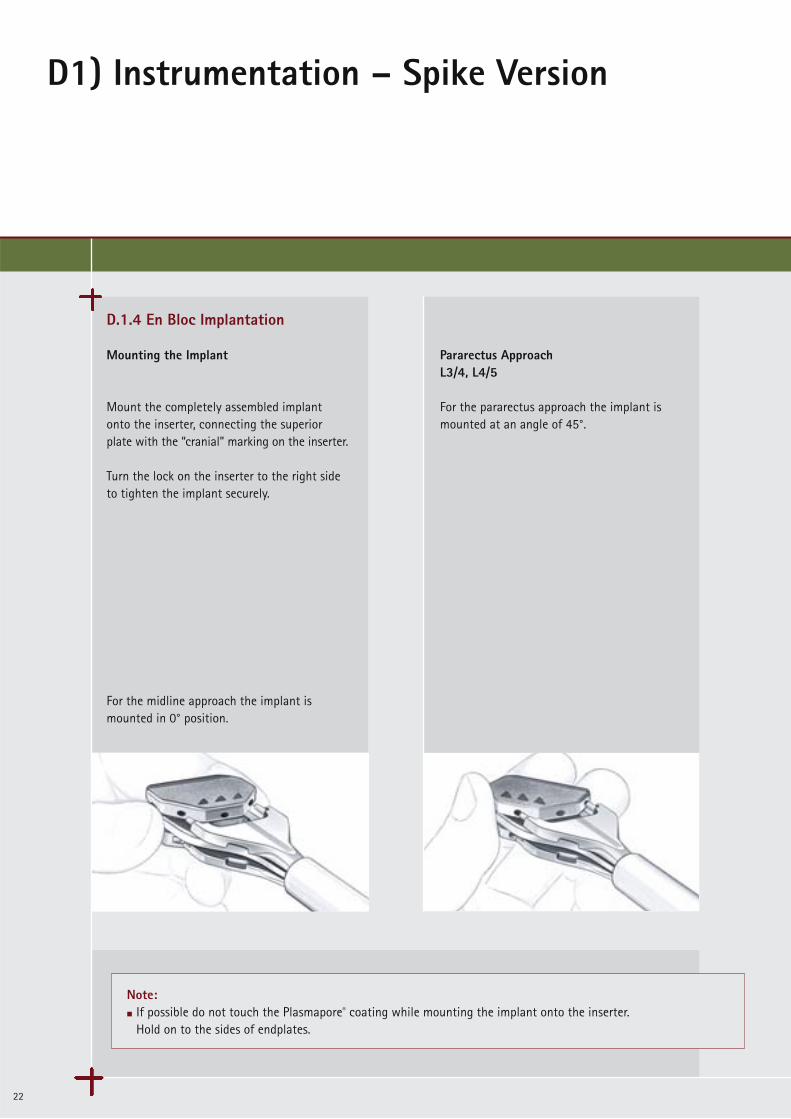
Note:m If possible do not touch the Plasmapore® coating while mounting the implant onto the inserter.
Hold on to the sides of endplates.
D1) Instrumentation – Spike Version
22
Mounting the Implant
Mount the completely assembled implant onto the inserter, connecting the superior plate with the “cranial” marking on the inserter.
Turn the lock on the inserter to the right sideto tighten the implant securely.
For the midline approach the implant is mounted in 0° position.
Pararectus ApproachL3/4, L4/5
For the pararectus approach the implant ismounted at an angle of 45°.
D.1.4 En Bloc Implantation

23
Check the midline position during the wholeimplantation. The marking on the insertermust be aligned with the midline marking.
Punch in the implant as far as possible underx-ray control to a maximum depth just in frontof the posterior rim of the vertebra.
midline
Note:m Bring in the implant in an almost 90° angle to
place both endplates to same ap-level.
m Use only the hammer with plastic end caps toimplant the artificial disc.
D1) Instrumentation – Spike Version
24
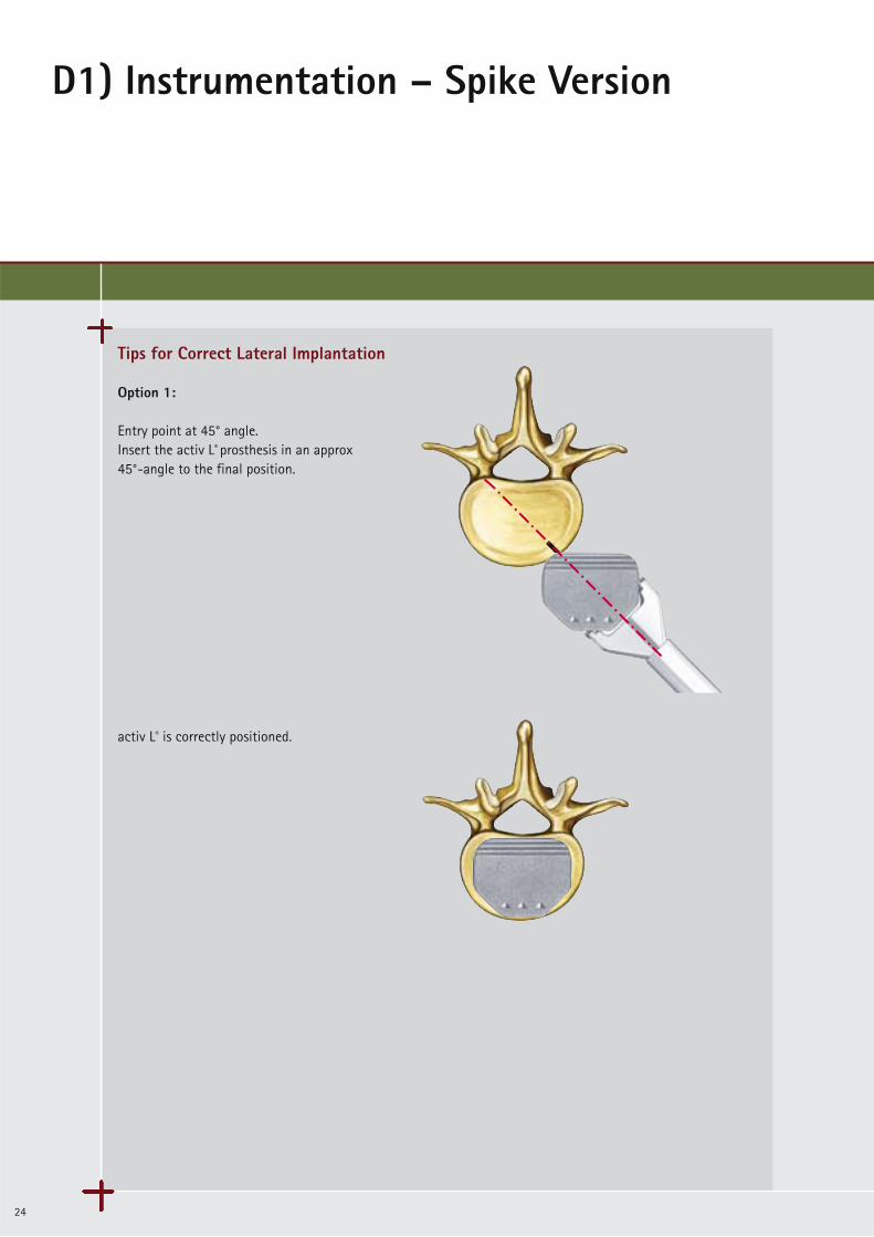
Tips for Correct Lateral Implantation
Option 1:
Entry point at 45° angle.Insert the activ L® prosthesis in an approx 45°-angle to the final position.
activ L® is correctly positioned.

25
Option 2:
Entry point a little bit ahead of the 45° line:Insert activ L® to the midline position.Then push the implant in straight ap-directionto the final position now.
Manipulation and correct placement is possible with the activ L® impactor.
Note:m Frequent x-ray checks in both planes are necessary. Best way might be to bring the implant in a slightly anterior
position, in regards of the 45° approach and an entry point located somewhat (1 - 2 mm) medially of the marking(as described in case 2). When the midline position is achieved, exact posterior positioning can be achieved with the impactor.
Note:m When in doubt, select a more anterior
entry point, since in this case correction is still possible.

D1) Instrumentation – Spike Version
26
D.1.4. En-Bloc-Implantation
spacer
button
Release the lock of the insertion instrument.
Turn the button on the instrument back to the left to remove the spacer.
Now the insertion instrument can be easily removed.

27
ap and lateral x-ray control of the inserted implant.
Source: Dr. Sola, University Hospital of Rostock

D2) Instrumentation – Keel Version
28
D.2.1. Chisels for Keel Fixation
The surgical steps of discectomy to size verification are performed in the same way as for the spike version; please refer to pages10 – 17.The keel version allows only the midline approach.For the keel version, the keel bed must be prepared using chisels. Depending on the combination of the implant version the double chisel or the single chisel has to beused.
ChiselsMount the chisel guide for the desired implant height and angle onto the handle.
Bring the safety depth stop into anterior position by turning the wheel to the right.
Introduce the chisel guide centrally into thedisc compartment and adjust the safety stopto the desired depth under x-ray control.
activ L®
keel version
activ L®
combined version
adjustment wheel for safety depth stop
Note:m The adjustable stop defines the depth to which the chisel can be hammered into the disc space.m The chiseling procedure will determine the central position and the alignment of the intervertebral disc prosthesis
in the intervertebral disc plane. The chisel penetration depth in ap-direction is controlled by the chisel depth stop which is adjusted on the chisel guide.
29
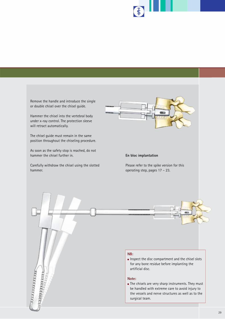
En bloc implantation
Please refer to the spike version for this operating step, pages 17 – 23.
Remove the handle and introduce the single or double chisel over the chisel guide.
Hammer the chisel into the vertebral body under x-ray control. The protection sleeve will retract automatically.
The chisel guide must remain in the same position throughout the chiseling procedure.
As soon as the safety stop is reached, do nothammer the chisel further in.
Carefully withdraw the chisel using the slotted hammer.
NB:m Inspect the disc compartment and the chisel slots
for any bone residue before implanting the artificial disc.
Note:m The chisels are very sharp instruments. They must
be handled with extreme care to avoid injury to the vessels and nerve structures as well as to the surgical team.
E) Correction of Implant Positionand Inlay Revision
30
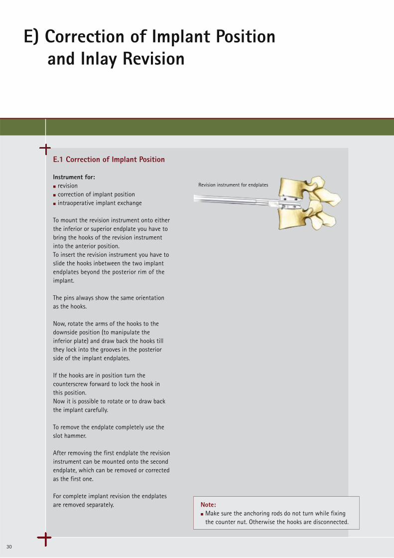
E.1 Correction of Implant Position
Instrument for: m revision m correction of implant positionm intraoperative implant exchange
To mount the revision instrument onto eitherthe inferior or superior endplate you have tobring the hooks of the revision instrument into the anterior position. To insert the revision instrument you have toslide the hooks inbetween the two implantendplates beyond the posterior rim of the implant.
The pins always show the same orientation as the hooks.
Now, rotate the arms of the hooks to thedownside position (to manipulate the inferior plate) and draw back the hooks tillthey lock into the grooves in the posterior side of the implant endplates.
If the hooks are in position turn thecounterscrew forward to lock the hook inthis position.Now it is possible to rotate or to draw backthe implant carefully.
To remove the endplate completely use theslot hammer.
After removing the first endplate the revisioninstrument can be mounted onto the secondendplate, which can be removed or correctedas the first one.
For complete implant revision the endplatesare removed separately.
Revision instrument for endplates
Note:m Make sure the anchoring rods do not turn while fixing
the counter nut. Otherwise the hooks are disconnected.

31
90º
nose hooks
counter nut
E) Correction of Implant Positionand Inlay Revision
32
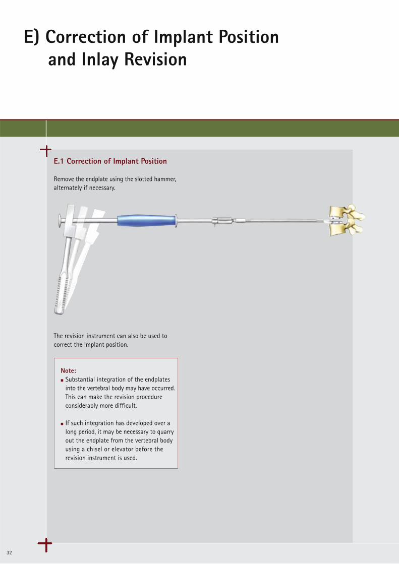
E.1 Correction of Implant Position
Remove the endplate using the slotted hammer,alternately if necessary.
The revision instrument can also be used tocorrect the implant position.
Note:m Substantial integration of the endplates
into the vertebral body may have occurred. This can make the revision procedure considerably more difficult.
m If such integration has developed over a long period, it may be necessary to quarryout the endplate from the vertebral body using a chisel or elevator before the revision instrument is used.
33
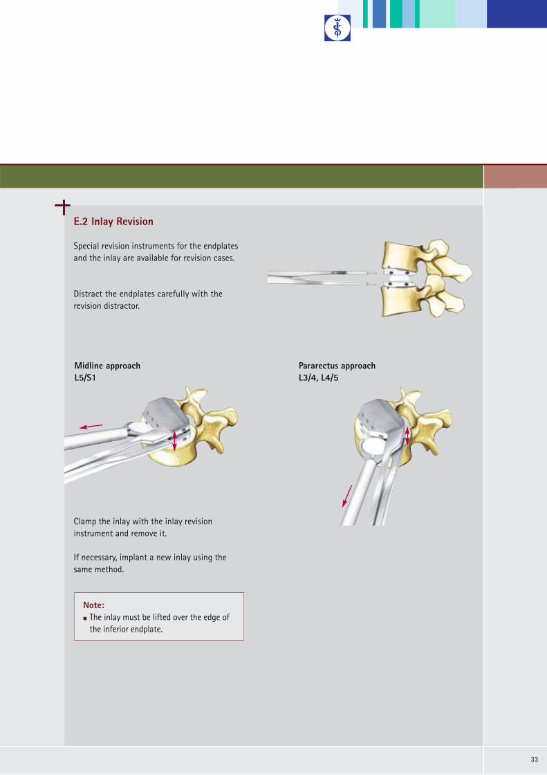
E.2 Inlay Revision
Special revision instruments for the endplatesand the inlay are available for revision cases.
Distract the endplates carefully with therevision distractor.
Clamp the inlay with the inlay revision instrument and remove it.
If necessary, implant a new inlay using the same method.
Note:m The inlay must be lifted over the edge of
the inferior endplate.
Midline approach L5/S1
Pararectus approach L3/4, L4/5

F1) Implant Overview
34
Implants
The implants are delivered sterile packed.
Height* 8.5 10 12 14PE Inlay SW965 SW966 SW967 SW968
*) The height given corresponds to the height of the implant measured at the posterior end.
Components
Superior Plate
Inferior Plate
S1 Superior Plate
S1 Inferior Plate
Size
S(26 x 31)
M(28 x 34.5)
L(30 x 39)
XL(33 x 40)
SW981KSW971K SW991K
SW982K
SW980K
SW986K
SW970K
SW976K
SW990K
SW996K
6°
11°
0°
6°
5°
Angl
e
SW972K SW992K
SW891K
SW890K
SW914KSW912K SW916K SW918K
SW888K
SW988KSW978K SW998K0° SW886K
SW892K
Endplates with Keel
Components
Superior Plate
Inferior Plate
S1 Inferior Plate
Size
S(26 x 31)
M(28 x 34.5)
L(30 x 39)
XL(33 x 40)
SW984KSW974K SW994K
SW985K
SW983K
SW987K
SW973K
SW977K
SW993K
SW997K
6°
11°
0°
5°
Angl
e
SW975K SW995K
SW894K
SW893K
S1 Superior Plate SW915KSW913K SW917K6° SW919K
SW889K
SW989KSW979K SW999K0° SW887K
SW895K
superior plate
inferior plate
superior plate
inferior plate
PE Inlay
Endplates with Spikes
35
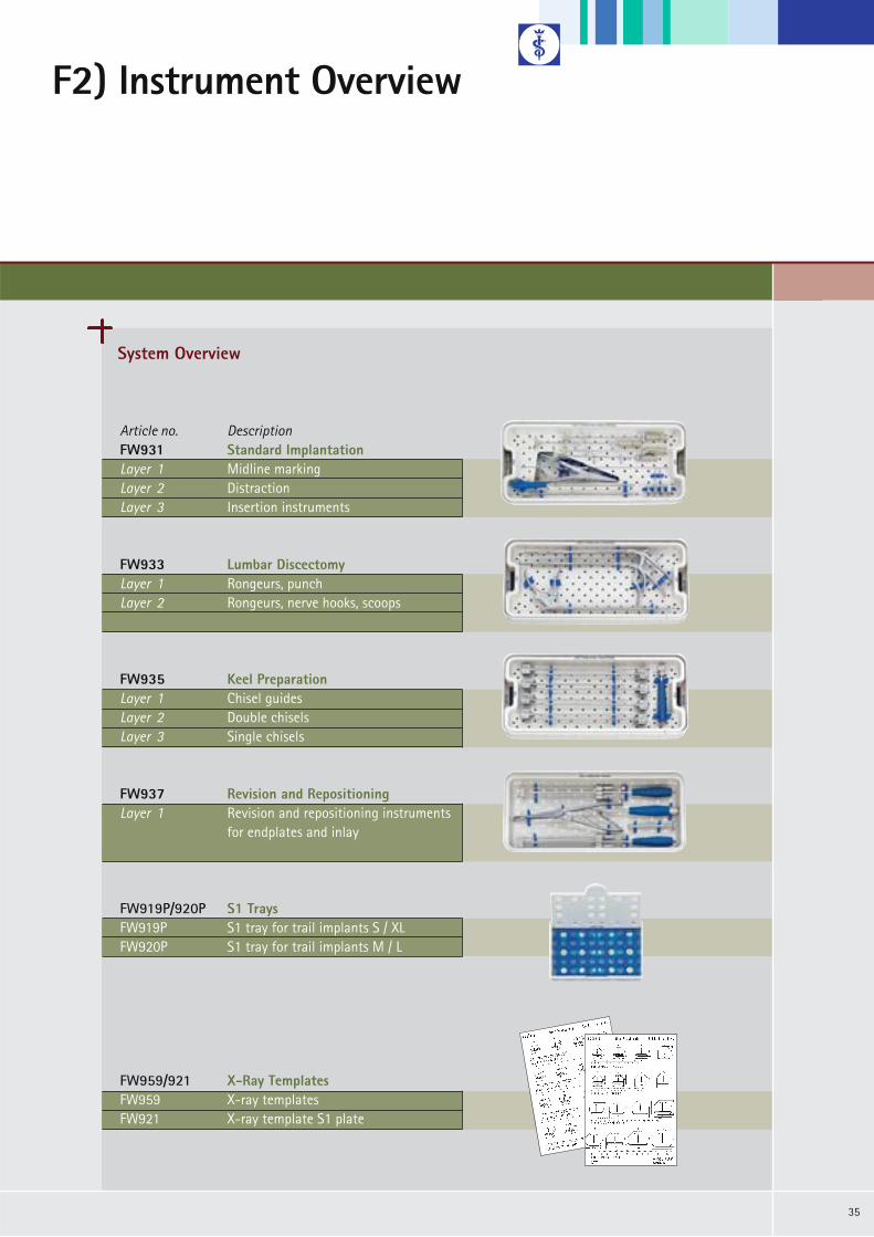
System Overview
Article no. DescriptionFW931 Standard Implantation Layer 1 Midline markingLayer 2 DistractionLayer 3 Insertion instruments
FW933 Lumbar DiscectomyLayer 1 Rongeurs, punchLayer 2 Rongeurs, nerve hooks, scoops
FW935 Keel Preparation Layer 1 Chisel guidesLayer 2 Double chiselsLayer 3 Single chisels
FW937 Revision and RepositioningLayer 1 Revision and repositioning instruments
for endplates and inlay
FW919P/920P S1 TraysFW919P S1 tray for trail implants S / XLFW920P S1 tray for trail implants M / L
F2) Instrument Overview
FW959/921 X-Ray TemplatesFW959 X-ray templatesFW921 X-ray template S1 plate
F2) Instrument Overview
36
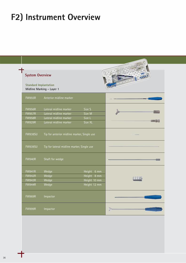
System Overview
Standard ImplantationMidline Marking - Layer 1
FW955R Anterior midline marker
FW938SU Tip for anterior midline marker, Single use
FW939SU Tip for lateral midline marker, Single use
FW940R Shaft for wedge
FW969R Impactor
FW999R Impactor
FW956R Lateral midline marker Size SFW957R Lateral midline marker Size MFW958R Lateral midline marker Size LFW929R Lateral midline marker Size XL
FW941R Wedge Height 6 mmFW942R Wedge Height 8 mmFW943R Wedge Height 10 mmFW944R Wedge Height 12 mm
37
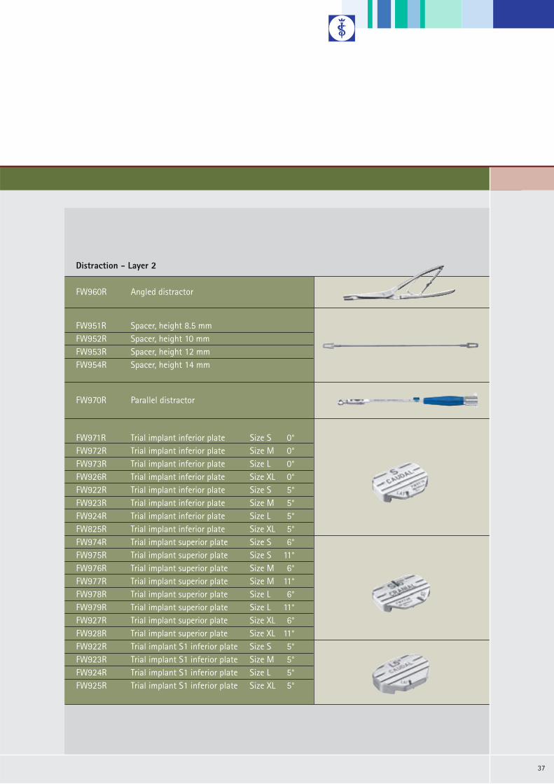
Legende Rotis regular 8/11ptFW951R Spacer, height 8.5 mmFW952R Spacer, height 10 mmFW953R Spacer, height 12 mmFW954R Spacer, height 14 mm
Distraction - Layer 2
FW960R Angled distractor
FW970R Parallel distractor
FW971R Trial implant inferior plate Size S 0°FW972R Trial implant inferior plate Size M 0°FW973R Trial implant inferior plate Size L 0°FW926R Trial implant inferior plate Size XL 0°FW922R Trial implant inferior plate Size S 5°FW923R Trial implant inferior plate Size M 5°FW924R Trial implant inferior plate Size L 5°FW825R Trial implant inferior plate Size XL 5°FW974R Trial implant superior plate Size S 6°FW975R Trial implant superior plate Size S 11°FW976R Trial implant superior plate Size M 6°FW977R Trial implant superior plate Size M 11°FW978R Trial implant superior plate Size L 6°FW979R Trial implant superior plate Size L 11°FW927R Trial implant superior plate Size XL 6°FW928R Trial implant superior plate Size XL 11°FW922R Trial implant S1 inferior plate Size S 5°FW923R Trial implant S1 inferior plate Size M 5°FW924R Trial implant S1 inferior plate Size L 5°FW925R Trial implant S1 inferior plate Size XL 5°
F2) Instrument Overview
38
System Overview
Legende Rotis regular 8/11pt
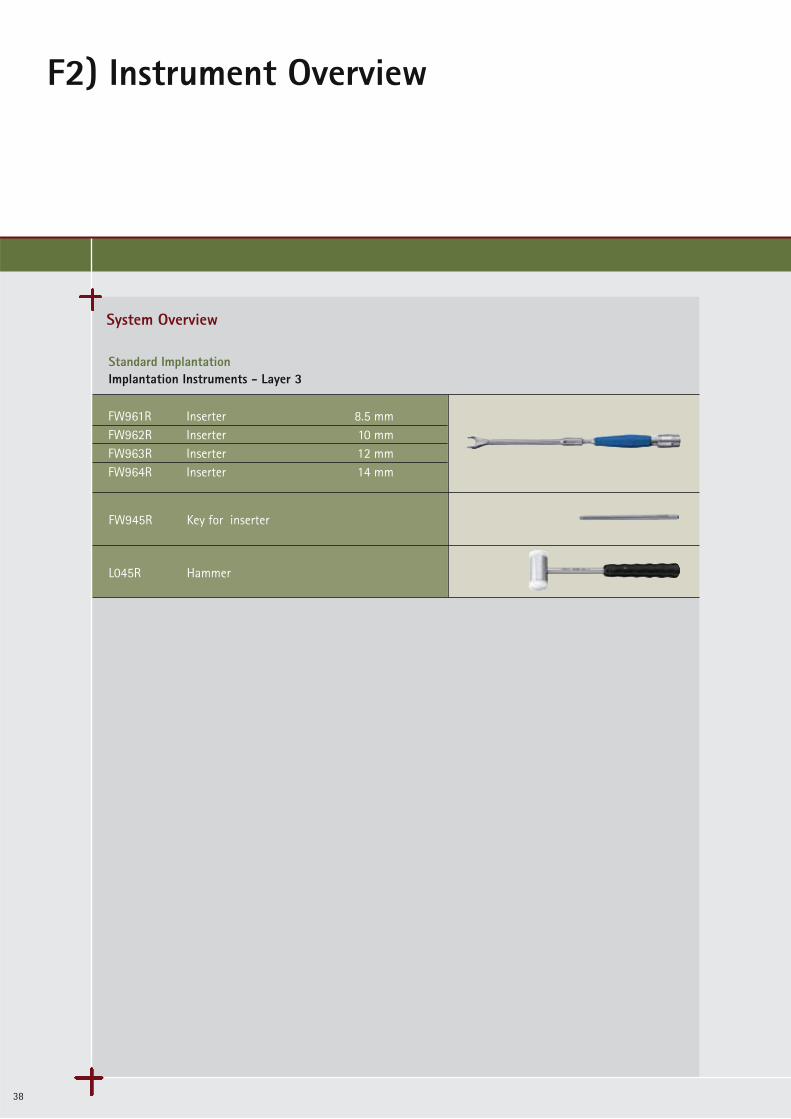
Standard ImplantationImplantation Instruments - Layer 3
FW945R Key for inserter
L045R Hammer
FW961R Inserter 8.5 mmFW962R Inserter 10 mmFW963R Inserter 12 mmFW964R Inserter 14 mm
39
Legende Rotis regular 8/11pt
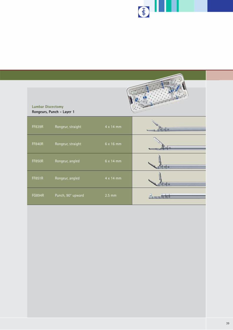
Lumbar DiscectomyRongeurs, Punch - Layer 1
FF839R Rongeur, straight 4 x 14 mm
FF840R Rongeur, straight 6 x 16 mm
FF850R Rongeur, angled 6 x 14 mm
FF851R Rongeur, angled 4 x 14 mm
FG894R Punch, 90° upward 2.5 mm

F2) Instrument Overview
40
System Overview
Legende Rotis regular 8/11pt
Lumbar DiscectomyCurettes, Nerve Hooks, Scoops - Layer 2
FK826R Curette, round 6.4 mm
FK822R Curette 7 x 5 mm
FK780R Scoop, straight 4.4 x 6.2 mm
FK781R Scoop, straight 5.2 x 7.3 mm
FK791R Scoop, angled 5.2 x 7.3 mm
FK392R Raspatory 8 mm
BT070R Probe hook

41
Legende Rotis regular 8/11pt
Keel PreparationChisel Guides - Layer 1
FW980R Handle for chisel guide
FW997R Osteotome
FW579R Slotted hammer
FW981R Chisel guide Height 8.5 mm 6°FW982R Chisel guide Height 10 mm 6°FW983R Chisel guide Height 12 mm 6°FW984R Chisel guide Height 14 mm 6°FW993R Chisel guide Height 8.5 mm 11°FW994R Chisel guide Height 10 mm 11°FW995R Chisel guide Height 12 mm 11°FW996R Chisel guide Height 14 mm 11°

F2) Instrument Overview
42
System Overview
Legende Rotis regular 8/11pt
Keel PreparationDouble Chisels - Layer 2
FW985R Double chisel Height 8.5 mmFW986R Double chisel Height 10 mmFW987R Double chisel Height 12 mmFW988R Double chisel Height 14 mm
Legende Rotis regular 8/11pt
Single Chisel - Layer 3
FW989R Single chisel Height 8.5 mmFW990R Single chisel Height 10 mmFW991R Single chisel Height 12 mmFW992R Single chisel Height 14 mm
43
Legende Rotis regular 8/11pt
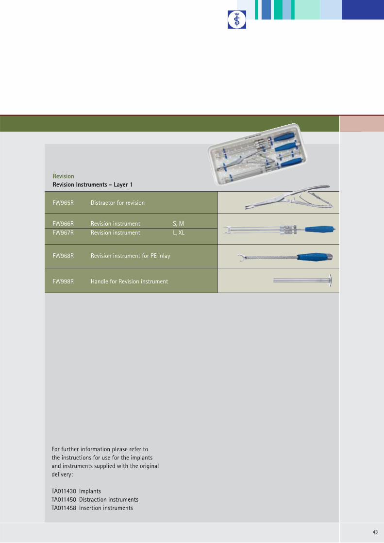
RevisionRevision Instruments - Layer 1
FW965R Distractor for revision
FW968R Revision instrument for PE inlay
FW998R Handle for Revision instrument
FW966R Revision instrument S, MFW967R Revision instrument L, XL
For further information please refer to the instructions for use for the implantsand instruments supplied with the original delivery:
TA011430 Implants TA011450 Distraction instruments TA011458 Insertion instruments

Brochure No. O27902
All rights reserved. Technical alterations are possible. This leaflet may be used for no other purposes than offering, buying and selling of our products. No part may be copied or reproduced in any form. In the case of misuse we retain the rights to recall our catalogues and pricelists and to take legal actions.
Aesculap AG
Am Aesculap-Platz78532 TuttlingenGermany
Phone +49 7461 95-0Fax +49 7461 95-2600
www.aesculap.de
0908/2/3