ah-08-02.4 vector solo 65kv applicator · vector solotm 65 kv applicator model: 79965 solventborne...
TRANSCRIPT

SERVICE MANUALSERVICE MANUALSERVICE MANUALSERVICE MANUALSERVICE MANUAL
AH-08-02.4AH-08-02.4AH-08-02.4AH-08-02.4AH-08-02.4December - 2011
IMPORIMPORIMPORIMPORIMPORTTTTTANTANTANTANTANT: Before using this equipment,: Before using this equipment,: Before using this equipment,: Before using this equipment,: Before using this equipment,
carefully read SAFETY PRECAUTIONS,carefully read SAFETY PRECAUTIONS,carefully read SAFETY PRECAUTIONS,carefully read SAFETY PRECAUTIONS,carefully read SAFETY PRECAUTIONS,
starting on page 1, and all instructions in thisstarting on page 1, and all instructions in thisstarting on page 1, and all instructions in thisstarting on page 1, and all instructions in thisstarting on page 1, and all instructions in this
manual. Keep this Service Manual for futuremanual. Keep this Service Manual for futuremanual. Keep this Service Manual for futuremanual. Keep this Service Manual for futuremanual. Keep this Service Manual for future
reference.reference.reference.reference.reference.
VECTVECTVECTVECTVECTOR SOLOOR SOLOOR SOLOOR SOLOOR SOLOTMTMTMTMTM
65 KV APPLICA65 KV APPLICA65 KV APPLICA65 KV APPLICA65 KV APPLICATTTTTOROROROROR
MODEL: 79965 Solventborne RS70-ASMODEL: 79965 Solventborne RS70-ASMODEL: 79965 Solventborne RS70-ASMODEL: 79965 Solventborne RS70-ASMODEL: 79965 Solventborne RS70-AS
Service Manual Price:Service Manual Price:Service Manual Price:Service Manual Price:Service Manual Price: €40.00 (Euro)40.00 (Euro)40.00 (Euro)40.00 (Euro)40.00 (Euro)
$50.00 (U.S.)$50.00 (U.S.)$50.00 (U.S.)$50.00 (U.S.)$50.00 (U.S.)

AH-08-02.4
NOTE: This manual has been changed from revision AH-08-02.3 to revision AH-08-02.4. Reasons for this change are noted under “Manual Change Summary” inside the back cover of this manual.

AH-08-02.4
SAFETY:SAFETY:SAFETY:SAFETY:SAFETY:
SAFETY PRECAUTIONS.........................................................................................................HAZARDS / SAFEGUARDS.....................................................................................................
PAGEPAGEPAGEPAGEPAGE
INTRODUCTION:INTRODUCTION:INTRODUCTION:INTRODUCTION:INTRODUCTION:
CONTENTSCONTENTSCONTENTSCONTENTSCONTENTS
GENERAL DESCRIPTION........................................................................................................79965 VECTOR SOLO 65KV SOLVENTBORNE SPECIFICATIONS...................................VECTOR SOLO 65KV SOLVENTBORNE ELECTROSTATICSPRAY APPLICATOR...............................................................................................................VECTOR SOLO 65KV TYPICAL SOLVENTBORNE INSTALLATION...................................
1-41-41-41-41-4
9-129-129-129-129-12
12-4
910
1112
Vector Solo 65kV Applicator - Contents
INSTALLATION:INSTALLATION:INSTALLATION:INSTALLATION:INSTALLATION:
79965 SOLO 65KV SOLVENTBORNE INSTALLATION........................................................INSTALLATION.........................................................................................................................MAPS - MANUAL APPLICATION PROCESS SHEET............................................................
13-1613-1613-1613-1613-16
13-141415
(Continued On Next Page)(Continued On Next Page)(Continued On Next Page)(Continued On Next Page)(Continued On Next Page)
ATEX/FM:ATEX/FM:ATEX/FM:ATEX/FM:ATEX/FM:
EUROPEAN ATEX DIRECTIVE...............................................................................................
EUROPEAN ATEX LABELS.....................................................................................................
FM CONFIGURATION DRAWING...........................................................................................
5-85-85-85-85-8
5
6
7-8
17-2017-2017-2017-2017-20OPERATION:OPERATION:OPERATION:OPERATION:OPERATION:
APPLICTOR OPERATION........................................................................................................FLUSHING / COLOR CHANGE PROCEDURE......................................................................FLUID NOZZLE / AIR CAP........................................................................................................
17-1818-1920
MAINTENANCE:MAINTENANCE:MAINTENANCE:MAINTENANCE:MAINTENANCE:
SUITABLE SOLVENTS FOR CLEANING VECTOR SOLO APPLICATORS.........................ROUTINE SCHEDULE..............................................................................................................APPLICATOR REPAIR..............................................................................................................AIR CAP.....................................................................................................................................FLUID NOZZLE..........................................................................................................................NEEDLE / ELECTRODE...........................................................................................................NEEDLE / ELECTRODE RESISTANCE TESTING.................................................................BARREL REMOVAL .................................................................................................................NEEDLE SHAFT REMOVAL / REPLACEMENT......................................................................POWER MODULE REMOVAL..................................................................................................HANDLE DISASSEMBLY..........................................................................................................POWER MODULE-FLUID FITTING REMOVAL......................................................................TEST AND MAINTENANCE KIT USAGE (79870-00)..............................................................TROUBLESHOOTING GUIDE.................................................................................................
2122-2323-242425-26262727-3031-3232-3333-3535-3637-3941
21-4121-4121-4121-4121-41
AH-08-02.4
Vector Solo 65kV Applicator - Contents
PAGEPAGEPAGEPAGEPAGE
PARTS IDENTIFICATION:PARTS IDENTIFICATION:PARTS IDENTIFICATION:PARTS IDENTIFICATION:PARTS IDENTIFICATION: 42-5542-5542-5542-5542-55
VECTOR SOLO 65KV APPLICATOR PARTSBREAKDOWN / PARTS LIST....................................................................................................VECTOR SOLO RS70-AS MODEL IDENTIFICATION.............................................................79911-00 / 79911-01 NEEDLE SHAFT / PARTS LIST..............................................................POWER MODULE REPLACEABLE PARTS / PARTS LIST....................................................ACCESSORIES / PARTS LIST..................................................................................................PARTS COMPARISON / TRANS-TECH. ATOMIZATION PARTS LIST.................................79555 TRANS-TECH. CONVERSION KITS AVAILABLE........................................................VECTOR SOLO RECOMMENDED SPARE PARTS................................................................
42-464446-474849-51525354
WARRANTY POLICIES:WARRANTY POLICIES:WARRANTY POLICIES:WARRANTY POLICIES:WARRANTY POLICIES: 5858585858
LIMITED WARRANTY................................................................................................................ 58
CONTENTS (Cont.)CONTENTS (Cont.)CONTENTS (Cont.)CONTENTS (Cont.)CONTENTS (Cont.)

AH-08-02.4

AH-08-02.4
SAFETY PRECAUTIONSSAFETY PRECAUTIONSSAFETY PRECAUTIONSSAFETY PRECAUTIONSSAFETY PRECAUTIONS
Before operating, maintaining or servicing anyITW Ransburg electrostatic coating system, readand understand all of the technical and safetyliterature for your ITW Ransburg products. Thismanual contains information that is important foryou to know and understand. This informationrelates to USER SAFETY and PREVENTINGEQUIPMENT PROBLEMS. To help you recognizethis information, we use the following symbols.Please pay particular attention to these sections.
A WARNING! states information to alert youA WARNING! states information to alert youA WARNING! states information to alert youA WARNING! states information to alert youA WARNING! states information to alert you
to a situation that might cause serious injuryto a situation that might cause serious injuryto a situation that might cause serious injuryto a situation that might cause serious injuryto a situation that might cause serious injury
if instructions are not followed.if instructions are not followed.if instructions are not followed.if instructions are not followed.if instructions are not followed.
A CAUTION! states information that tellsA CAUTION! states information that tellsA CAUTION! states information that tellsA CAUTION! states information that tellsA CAUTION! states information that tells
how to prevent damage to equipment or howhow to prevent damage to equipment or howhow to prevent damage to equipment or howhow to prevent damage to equipment or howhow to prevent damage to equipment or how
to avoid a situation that might cause minorto avoid a situation that might cause minorto avoid a situation that might cause minorto avoid a situation that might cause minorto avoid a situation that might cause minor
injury.injury.injury.injury.injury.
A NOTE is information relevant to theA NOTE is information relevant to theA NOTE is information relevant to theA NOTE is information relevant to theA NOTE is information relevant to the
procedure in progress.procedure in progress.procedure in progress.procedure in progress.procedure in progress.
While this manual lists standard specificationsand service procedures, some minor deviationsmay be found between this literature and yourequipment. Differences in local codes and plantrequirements, material delivery requirements, etc.,make such variations inevitable. Compare thismanual with your system installation drawingsand appropriate Ransburg equipmentmanuals to reconcile such differences.
Careful study and continued use of this manual willprovide a better understanding of the equipmentand process, resulting in more efficient operation,longer trouble-free service and faster, easiertroubleshooting. If you do not have the manualsand safety literature for your ITW Ransburg system,contact your local ITW Ransburg representativeor ITW Ransburg.
SAFETYSAFETYSAFETYSAFETYSAFETY
>The user MUSTMUSTMUSTMUSTMUST read and be familiar
with the Safety Section in this manual andthe ITW Ransburg safety literature thereinidentified.
> This hand held device is intended to
be used by trained personnel ONLY.
> This manual MUSTMUSTMUSTMUSTMUST be read and thor-
oughly understood by ALLALLALLALLALL personnel whooperate, clean or maintain this equipment!Special care should be taken to ensure thatthe WARNINGSWARNINGSWARNINGSWARNINGSWARNINGS and safety requirementsfor operating and servicing the equipmentare followed. The user should be aware ofand adhere to ALLALLALLALLALL local building and firecodes and ordinances as well as NFPA-NFPA-NFPA-NFPA-NFPA-
33 SAFETY STANDARD, or applica-33 SAFETY STANDARD, or applica-33 SAFETY STANDARD, or applica-33 SAFETY STANDARD, or applica-33 SAFETY STANDARD, or applica-
ble country safety standards ble country safety standards ble country safety standards ble country safety standards ble country safety standards prior toinstalling, operating, and/or servicing thisequipment.
W A R N I N GW A R N I N GW A R N I N GW A R N I N GW A R N I N G!!!!!
>The hazards shown on the following
page may occur during the normal use ofthis equipment. Please read the hazardchart beginning on page 2.
W A R N I N GW A R N I N GW A R N I N GW A R N I N GW A R N I N G!!!!!
11111
Vector Solo 65kV Applicator - Safety

AH-08-02.4
Vector Solo 65kV Applicator - Safety
22222
Spray AreaSpray AreaSpray AreaSpray AreaSpray Area
AREAAREAAREAAREAAREA
Tells where hazards
may occur.
HAZARDHAZARDHAZARDHAZARDHAZARD
Tells what the hazard is.
SAFEGUARDSSAFEGUARDSSAFEGUARDSSAFEGUARDSSAFEGUARDS
Tells how to avoid the hazard.
Fire Hazard
Improper or inadequate opera-tion and maintenance procedureswill cause a fire hazard.
Protection against inadvertentarcing that is capable of causingfire or explosion is lost if anysafety interlocks are disabledduring operation. Frequent powersupply shutdown indicates aproblem in the system requiring
correction.
Fire extinguishing equipment must be present in thespray area and tested periodically.
Spray areas must be kept clean to prevent theaccumulation of combustible residues.
Smoking must never be allowed in the spray area.
The high voltage supplied to the atomizer must beturned off prior to cleaning, flushing or maintenance.
When using solvents for cleaning:
Those used for equipment flushing should haveflash points equal to or higher than those of thecoating material.
Those used for general cleaning must have flashpoints above 100oF (37.8oC).
Spray booth ventilation must be kept at the ratesrequired by local and/or country codes. In addition,ventilation must be maintained during cleaningoperations using flammable or combustible solvents.
Electrostatic arcing must be prevented.
Test only in areas free of combustible material.
Testing may require high voltage to be on, but onlyas instructed.
Non-factory replacement parts or unauthorizedequipment modifications may cause fire or injury.
If used, the key switch bypass is intended for useonly during setup operations. Production shouldnever be done with safety interlocks disabled.
The paint process and equipment should be set upand operated in accordance with local and/or countrysafety codes.

AH-08-02.4
Vector Solo 65kV Applicator - Safety
33333
AREAAREAAREAAREAAREA
Tells where hazards
may occur.
HAZARDHAZARDHAZARDHAZARDHAZARD
Tells what the hazard is.
SAFEGUARDSSAFEGUARDSSAFEGUARDSSAFEGUARDSSAFEGUARDS
Tells how to avoid the hazard.
ElectricalElectricalElectricalElectricalElectrical
EquipmentEquipmentEquipmentEquipmentEquipment
High voltage equipment isutilized. Arcing in areas offlammable or combustible mat-erials may occur. Personnel areexposed to high voltage duringoperation and maintenance.
Protection against inadvertentarcing that may cause a fire orexplosion is lost if safety circuitsare disabled during operation.
An electrical arc can ignitecoating materials and cause afire or explosion.
Turn the power module OFF before working onthe equipment.
Test only in areas free of flammable or combus-tible material.
Testing may require high voltage to be on, butonly as instructed.
Production should never be done with the safetycircuits disabled.
Before turning the high voltage on, make sure noobjects are within the sparking distance.
ExplosionExplosionExplosionExplosionExplosion
Hazard /Hazard /Hazard /Hazard /Hazard /
IncompatibleIncompatibleIncompatibleIncompatibleIncompatible
MaterialsMaterialsMaterialsMaterialsMaterials
Halogenated hydrocarbon solvents,for example: methylene chlorideand 1,1,1, - Trichloroethane, arenot chemically compatible with thealuminum that might be used inmany system components. Thechemical reaction caused by thesesolvents reacting with aluminumcan become violent and lead to anequipment explosion.
Spray applicators require that aluminum inlet fittingsbe replaced with stainless steel. (See "Accessories"in the "Parts Identification" section.) Aluminum iswidely used in other spray application equipment -such as material pumps, regulators, valves, etc.Check all other equipment items before use andmake sure they can also be used safely with thesesolvents. Read the label or data sheet for thematerial you intend to spray. If in doubt as towhether or not a coating or cleaning material iscompatible, contact your material supplier. Anyother type of solvent may be used with aluminumequipment.
Toxic SubstancesToxic SubstancesToxic SubstancesToxic SubstancesToxic Substances Certain material may be harmfulif inhaled, or if there is contactwith the skin.
Follow the requirements of the Material Safety DataSheet supplied by coating material manufacturer.
Adequate exhaust must be provided to keep the airfree of accumulations of toxic materials.
Use a mask or respirator whenever there is achance of inhaling sprayed materials. The maskmust be compatible with the material being sprayedand its concentration. Equipment must be asprescribed by an industrial hygienist or safetyexpert, and be approved.

AH-08-02.4
Vector Solo 65kV Applicator - Safety
44444
AREAAREAAREAAREAAREA
Tells where hazards
may occur.
HAZARDHAZARDHAZARDHAZARDHAZARD
Tells what the hazard is.
SAFEGUARDSSAFEGUARDSSAFEGUARDSSAFEGUARDSSAFEGUARDS
Tells how to avoid the hazard.
Spray AreaSpray AreaSpray AreaSpray AreaSpray Area
General Use andGeneral Use andGeneral Use andGeneral Use andGeneral Use and
MaintenanceMaintenanceMaintenanceMaintenanceMaintenance
Electrostatic Arcing
Improper operation or main-tenance may create a hazard.
Personnel must be properlytrained in the use of thisequipment.
Never operate the applicator without properlygrounding the following.
A. Operators
Operators must be grounded. Rubber soledinsulating shoes should not be worn. Groundingleg or wrist straps may be used.
Operators must maintain contact with the handleof the applicator. If work gloves are used, thepalmsection must be cut out.
Operators must remove from themselves allmetal objects that are not grounded.
NOTE:NOTE:NOTE:NOTE:NOTE: REFER TO NFPA-33 REGARDINGOPERATOR GROUNDING OR SPECIFICCOUNTRY SAFETY CODE.
B. Parts being sprayed. Resistance between thepart and a grounded conveyor must not exceed1 megohm.
C. Every metal and conductive object in the sprayarea. This includes the booth, parts hangers,fire extinguishers, conductive flooring, etc.
Grounded conductive flooring must be provided inthe spray area.
Turn off voltage at the power module before flushingout, cleaning, or removing any parts from theapplicator.
Never install an applicator into a fluid system using
an isolated solvent supply.
Do not touch applicator electrode while applicator isenergized.
Personnel must be given training in accordancewith the requirements of NFPA-33.
Instructions and safety precautions must be readand understood prior to using this equipment.
Comply with appropriate local, state, and nationalcodes governing ventilation, fire protection, operationmaintenance, and housekeeping.

AH-08-02.4
Vector Solo 65kV Applicators- Atex/FM
55555
EUROPEAN AEUROPEAN AEUROPEAN AEUROPEAN AEUROPEAN ATEX DIRECTIVE 94/9/EC, ANNEX II, 1.0.6TEX DIRECTIVE 94/9/EC, ANNEX II, 1.0.6TEX DIRECTIVE 94/9/EC, ANNEX II, 1.0.6TEX DIRECTIVE 94/9/EC, ANNEX II, 1.0.6TEX DIRECTIVE 94/9/EC, ANNEX II, 1.0.6
The following instructions apply to equipmentcovered by certificate number Sira 08ATEX5060:
1. The equipment may be used with flammablegases and vapors with apparatus groups II andwith temperature class T6.
2. The equipment is only certified for use in ambienttemperatures in the range 0°C to +40°C andshould not be used outside this range.
3. Installation shall be carried out by suitably trainedpersonnel in accordance with the applicable codeof practice e.g. EN 60079-14:1997.
4. Inspection and maintenance of this equipmentshall be carried out by suitably trained personnelin accordance with the applicable code of practicee.g. EN 60079-17.
5. Repair of this equipment shall be carried out bysuitable trained personnel in accordance with theapplicable code of practice e.g. EN 60079-19.
6. Putting into service, use, assembling, andadjustment of the equipment shall be fitted bysuitably trained personnel in accordance with themanufacturer's documentation.
Refer to the "Table of Contents" of this servicemanual:
a. Installationb. Operationc. Maintenanced. Parts Identification
7. Components to be incorporated into or used asreplacement parts of the equipment shall be fittedby suitably trained personnel in accordance withthe manufacturer's documentation.
8. The certification of this equipment relies uponthe following materials used in its construction:
If the equipment is likely to come into contact withaggressive substances, then it is the responsibilityof the user to take suitable precautions that preventit from being adversely affected, thus ensuringthat the type of protection provided by the equipmentis not compromised.
Aggressive substances: e.g. acidic liquids orgases that may attack metals, or solvents thatmay affect polymeric materials.
Suitable precautions: e.g. regular checks as partof routine inspections or establishing from thematerial's data sheets that it is resistant to specificchemicals.
Refer to "Specifications" in the "Introduction"section:
a. All fluid passages contain stainless steel or nylon fittings.
b. High voltage cascade is encapsulated with a solvent resistant epoxy.
9. A recapitulation of the certification marking isdetailed in the "ATEX" section, on the next page,drawing numbers: 79846-01 and 79852-01.
10. The characteristics of the equipment shall bedetailed e.g. electrical, pressure, and voltageparameters.
The manufacturer should note that, on beingThe manufacturer should note that, on beingThe manufacturer should note that, on beingThe manufacturer should note that, on beingThe manufacturer should note that, on being
put into service, the equipment must beput into service, the equipment must beput into service, the equipment must beput into service, the equipment must beput into service, the equipment must be
accompanied by a translation of theaccompanied by a translation of theaccompanied by a translation of theaccompanied by a translation of theaccompanied by a translation of the
instructions in the language or languages ofinstructions in the language or languages ofinstructions in the language or languages ofinstructions in the language or languages ofinstructions in the language or languages of
the country in which the equipment is to bethe country in which the equipment is to bethe country in which the equipment is to bethe country in which the equipment is to bethe country in which the equipment is to be
used and by the instructions in the originalused and by the instructions in the originalused and by the instructions in the originalused and by the instructions in the originalused and by the instructions in the original
language.language.language.language.language.

AH-08-02.4
Vector Solo 65kV Applicator - Atex/FM
66666
VVVVVector Solo 79965 Aector Solo 79965 Aector Solo 79965 Aector Solo 79965 Aector Solo 79965 ATEXTEXTEXTEXTEX
Product Marking DefinitionsProduct Marking DefinitionsProduct Marking DefinitionsProduct Marking DefinitionsProduct Marking DefinitionsEx Certificate Number: Sira 08ATEX5060
Sira = Notified Body performing EC-typeexamination08 = Year of certificationATEX = Reference to ATEX Directive5 = Protection Concept Code (code 5 is titledEncapsulation)060 = Document serial numberX = Special conditions for safe use apply
Special conditions for safe use: The Vector Solo79965 Applicators shall only be used withassociated Air Hose Assembly.
Product MarkingProduct MarkingProduct MarkingProduct MarkingProduct Marking
II 2 GII 2 GII 2 GII 2 GII 2 G
Ex = Specific marking of explosive protectionII = Equipment Group hazardous area charac-teristics2 = Equipment CategoryG = Type of explosive atmosphere (gases, vapors,or mists)
EEx 0.24mJEEx 0.24mJEEx 0.24mJEEx 0.24mJEEx 0.24mJ = The Vector Solo 79965 Applicatorsare suitable for use in manual spraying installationscomplying with EN 50 050 as they are a Type Aclass with a discharge energy limit of 0.24mJ.
Label 79846-01Label 79846-01Label 79846-01Label 79846-01Label 79846-01
Label 79852-01Label 79852-01Label 79852-01Label 79852-01Label 79852-01
FM ConfigurationFM ConfigurationFM ConfigurationFM ConfigurationFM ConfigurationThis applicator is FM approved when configuredto drawing 79944 shown on pages 7 and 8.

AH-08-02.4
VECTOR SOLO RS70-AS SOLVENT BASED
79965 - ABCDEBASE
MODEL NO.OPTION
DESIGNATIONS
(ORDERING INFORMATION ONLY)
CONFIGURATION DWG. 79944 REV C
"B" DESIGNATIONS
"A" DESIGNATIONS
"E" DESIGNATIONS
"C" DESIGNATIONS
"D" DESIGNATIONS
77777
Vector Solo 65kV Applicators- Atex/FM

AH-08-02.4
VECTOR SOLO RS70-AS SOLVENT BASED
79965 - ABCDEBASE
MODEL NO.OPTION
DESIGNATIONS
(ORDERING INFORMATION ONLY)
CONFIGURATION DWG. 79944 REV C
APPROVED SPARE FLUID NOZZLES LIST79377-46 (1.06mm ID, STD. WEAR), 79377-47 (.71mm ID, STD. WEAR),79377-48 (1.19mm ID, STD. WEAR), 79377-144 (1.40mm ID, HIGH WEAR),79377-145 (1.78mm ID, HIGH WEAR), 79377-146 (1.06mm ID, HIGH WEAR),79377-147 (.71mm ID, HIGH WEAR), 79552-244 (1.40mm ID, STD. WEAR),79552-344 (1.40mm ID, HIGH WEAR), 79552-345 (1.78mm ID, HIGH WEAR)
OPTION "A" DESIGNATIONSAIR HOSE TYPE AND LENGTH
1 FOR STANDARD AIR HOSE ASSEMBLY, 10 METER (33')-PART NUMBER: 79727-102 FOR STANDARD AIR HOSE ASSEMBLY, 15 METER (49')-PART NUMBER: 79727-153 FOR STANDARD AIR HOSE ASSEMBLY, 20 METER (66')-PART NUMBER: 79727-204 FOR STANDARD AIR HOSE ASSEMBLY, 30 METER (99')-PART NUMBER: 79727-305 FOR QD AIR HOSE ASSEMBLY, 10 METER (33')-PART NUMBER: 79727-116 FOR QD AIR HOSE ASSEMBLY, 15 METER (49')-PART NUMBER: 79727-167 FOR QD AIR HOSE ASSEMBLY, 20 METER (66')-PART NUMBER: 79727-218 FOR QD AIR HOSE ASSEMBLY, 30 METER (99')-PART NUMBER: 79727-31
OPTION "C" DESIGNATIONSTRIGGER TYPE
2 FOR TWO FINGER TRIGGER-PART NUMBER: 79787-00
OPTION "B" DESIGNATIONSFLUID INLET TUBE
1 FOR STANDARD FLUID TUBE, .093" ID-PART NUMBER: 79878-012 FOR COILED FLUID TUBE, .125" ID-PART NUMBER: 79871-003 FOR FLUID TUBE, 1/8" ID-PART NUMBER: 79878-024 FOR FLUID TUBE, 1/4" ID-PART NUMBER: 79878-03
OPTION "D" DESIGNATIONSSPRAY TECHNOLOGY
0 FOR STANDARD SPRAY, 65V CAP, #44 NOZZLE-PART NUMBER: 79374-65 & 79377-441 FOR STANDARD SPRAY, 65V CAP, #45 NOZZLE-PART NUMBER: 79374-65 & 79377-452 FOR TRANSTECH SPRAY, 122V CAP, #245 NOZZLE-PART NUMBER: 79374-122 & 79552-2453 FOR ROUND SPRAY-PART NUMBER: 79662-00 & 79559-004 FOR STANDARD SPRAY, 65V CAP, #48 NOZZLE-PART NUMBER; 79374-65 & 79377-48
OPTION "E" DESIGNATIONSFLUID HOSE LENGTH
0 FOR NO FLUID HOSE1 FOR FLUID HOSE, 10m-PART NUMBER: 79548-102 FOR FLUID HOSE, 15m-PART NUMBER: 79548-153 FOR FLUID HOSE, 20m-PART NUMBER: 79548-204 FOR FLUID HOSE, 30m-PART NUMBER: 79548-31
88888
Vector Solo 65kV Applicator - Atex/FM

AH-08-02.4
GENERAL DESCRIPTIONGENERAL DESCRIPTIONGENERAL DESCRIPTIONGENERAL DESCRIPTIONGENERAL DESCRIPTION
The Vector Vector Vector Vector Vector SoloSoloSoloSoloSoloTM TM TM TM TM 65kV Applicator65kV Applicator65kV Applicator65kV Applicator65kV Applicator is an airatomizing applicator powered only by a pressurizedair source. Pressurized air creates rotation of aturbine generator that powers a cascade. Thecascade generates a high voltage DC charge tothe electrode creating an electrostatic field betweenthe atomizer and the target.
A regulated pressure fluid system delivers coatingmaterial to the atomizer. At the time of triggeringthe applicator, fan and atomization air is introduced,which atomizes the coating material into a spraymist. The atomized spray particles under theinfluence of the electrostatic field becomeelectrically charged. The charged particles areattracted to, and deposited on, the target object.The forces between the charged particles and thegrounded target are sufficient to turn most normaloverspray around and deposit it on the backsurface of the target. Therefore, a high percentageof the coating is deposited on the target.
One of the many features of the Vector Soloapplicator system is that the electrical energy,which is available from the resistive chargingelectrode, is limited to the optimum level of safetyand efficiency. The system is incapable of releasingsufficient electrical or thermal energy during normaloperating conditions to cause ignition of specifichazardous materials in their most easily ignitedconcentrations in air.
As the applicator electrode approaches ground,applicator circuitry causes the high voltage toapproach zero while the current approaches itsmaximum value.
INTRODUCTIONINTRODUCTIONINTRODUCTIONINTRODUCTIONINTRODUCTION
Vector Solo 65kV Applicator - Introduction
99999
NOTESNOTESNOTESNOTESNOTES

AH-08-02.4
Vector Solo 65kV Applicator - Introduction
1010101010
Fluid FlowFluid FlowFluid FlowFluid FlowFluid Flow
Capacity:Capacity:Capacity:Capacity:Capacity: 1000 ml/minute**
Wetted Parts:Wetted Parts:Wetted Parts:Wetted Parts:Wetted Parts: Stainless, polyethylene,nylon, acetal polymer
Operating Pressure (Air Spray)Operating Pressure (Air Spray)Operating Pressure (Air Spray)Operating Pressure (Air Spray)Operating Pressure (Air Spray)
Fluid:Fluid:Fluid:Fluid:Fluid: (0-6.9 bar) 0-100 psi
Air :Air :Air :Air :Air : (0-6.9 bar) 0-100 psi
Ambient Temp.:Ambient Temp.:Ambient Temp.:Ambient Temp.:Ambient Temp.: 40°C to 0°C(104°F to 32°F)
Consumption:Consumption:Consumption:Consumption:Consumption: 470 SLPM (16.6 SCFM) @2.8 bar (40 psig) @ HandleInlet
Sound Level:Sound Level:Sound Level:Sound Level:Sound Level: 92dB (A) @ 2.8 bar(40 psig) Inlet,1m from applicator
Vibration Level:Vibration Level:Vibration Level:Vibration Level:Vibration Level: 0.065 m/S2 @ 2.8 bar(40 psig) @ Handle Inlet
** This reflects the maximum fluid volume the appli-cator can deliver. The maximum spray volume thatcan be effectively atomized depends on fluid rheol-ogy, spray technology, and finish quality required.
Applicator Length:Applicator Length:Applicator Length:Applicator Length:Applicator Length: 257mm (10.1-inches)
Weight:Weight:Weight:Weight:Weight: 834 grams (29.4 oz.)
Hose 79727-XXHose 79727-XXHose 79727-XXHose 79727-XXHose 79727-XX
Lengths (Std):Lengths (Std):Lengths (Std):Lengths (Std):Lengths (Std): 10m, 15m, 20m, and 30m
Atomizer NozzleAtomizer NozzleAtomizer NozzleAtomizer NozzleAtomizer Nozzle
Assembly (Std):Assembly (Std):Assembly (Std):Assembly (Std):Assembly (Std): 79374-65, 79377-44 (1.4mm)
Operating Voltage:Operating Voltage:Operating Voltage:Operating Voltage:Operating Voltage: 65kV DC (-) maximum
Current Output:Current Output:Current Output:Current Output:Current Output: 130 microamperes maximum
Paint Resistance:*Paint Resistance:*Paint Resistance:*Paint Resistance:*Paint Resistance:* .1 MΩ to ∞*****(Use Model No. 76652, Test Equipment)
Part Sprayability:Part Sprayability:Part Sprayability:Part Sprayability:Part Sprayability: Determine sprayability ofpart to be coated using76652, Test Equipment
(See current "Paint, HV & SCI Test Equipment"service manual.)
79965 VECT79965 VECT79965 VECT79965 VECT79965 VECTOR SOLO 65KV SOLOR SOLO 65KV SOLOR SOLO 65KV SOLOR SOLO 65KV SOLOR SOLO 65KV SOLVENTBORNEVENTBORNEVENTBORNEVENTBORNEVENTBORNE
SPECIFICASPECIFICASPECIFICASPECIFICASPECIFICATIONSTIONSTIONSTIONSTIONS
Environmental/PhysicalEnvironmental/PhysicalEnvironmental/PhysicalEnvironmental/PhysicalEnvironmental/Physical
ElectricalElectricalElectricalElectricalElectrical
MechanicalMechanicalMechanicalMechanicalMechanical

AH-08-02.4
Vector Solo 65kV Applicator - Introduction
1111111111
Figure 1: Vector Solo 65kV Solventborne Electrostatic Spray ApplicatorFigure 1: Vector Solo 65kV Solventborne Electrostatic Spray ApplicatorFigure 1: Vector Solo 65kV Solventborne Electrostatic Spray ApplicatorFigure 1: Vector Solo 65kV Solventborne Electrostatic Spray ApplicatorFigure 1: Vector Solo 65kV Solventborne Electrostatic Spray Applicator
1
2
3
4
5
6
7
No.No.No.No.No. DescriptionDescriptionDescriptionDescriptionDescription
Needle/Electrode
Barrel
Replaceable Hook
Fan Air Adjustment
Fluid Needle Travel Adjustment
Fluid Hose Connection
Air Inlet Connection
VECTVECTVECTVECTVECTOR SOLO 65KV SOLOR SOLO 65KV SOLOR SOLO 65KV SOLOR SOLO 65KV SOLOR SOLO 65KV SOLVENTBORNE ELECTROSTVENTBORNE ELECTROSTVENTBORNE ELECTROSTVENTBORNE ELECTROSTVENTBORNE ELECTROSTAAAAATICTICTICTICTICSPRASPRASPRASPRASPRAYYYYY APPLICA APPLICA APPLICA APPLICA APPLICATTTTTOROROROROR
8
9
10
11
12
13
No.No.No.No.No. DescriptionDescriptionDescriptionDescriptionDescription
kV Setpoint Switch
Voltage On/Off Indicator Light
Trigger
Turbine Air Exhaust
Voltage On/Off Lever
Power Module
10
13
4 5
1
2
3
67
8
9
11
12

AH-08-02.4
Vector Solo 65kV Applicator - Introduction
1212121212
Figure 2: Vector Solo 65kV Solventborne Typical InstallationFigure 2: Vector Solo 65kV Solventborne Typical InstallationFigure 2: Vector Solo 65kV Solventborne Typical InstallationFigure 2: Vector Solo 65kV Solventborne Typical InstallationFigure 2: Vector Solo 65kV Solventborne Typical Installation
1
2
3
4
5
6
No.No.No.No.No. DescriptionDescriptionDescriptionDescriptionDescription
Vector Solo
Ball Valve
Air Regulator W/Pressure Gauge
Air / Water Separator
Main Air Supply Line
Fluid Supply (Grounded)
VECTVECTVECTVECTVECTOR SOLO 65KV SOLOR SOLO 65KV SOLOR SOLO 65KV SOLOR SOLO 65KV SOLOR SOLO 65KV SOLVENTBORNE TYPICALVENTBORNE TYPICALVENTBORNE TYPICALVENTBORNE TYPICALVENTBORNE TYPICALINSTINSTINSTINSTINSTALLAALLAALLAALLAALLATIONTIONTIONTIONTION
7
8
9
10
No.No.No.No.No. DescriptionDescriptionDescriptionDescriptionDescription
Fluid Regulator
Air Hose (79727-XX)
Air Hose Ground Wire
Fluid Line

AH-08-02.4
INSTINSTINSTINSTINSTALLAALLAALLAALLAALLATIONTIONTIONTIONTION
Air HoseAir HoseAir HoseAir HoseAir Hose
Vector Solo 65kV Applicator - Installation
1313131313
Fluid Hose RecommendationFluid Hose RecommendationFluid Hose RecommendationFluid Hose RecommendationFluid Hose RecommendationITW Ransburg recommends using a 79548 FluidHose Assembly. This assembly is made tospecifically fit the fluid fitting size engineered intothe applicator. This hose is available from yourauthorized ITW Ransburg distributor. Availablehose lengths are listed in "Accessories" in the"Parts Identification" section of this manual.
> Any user installed fluid hose used must
be rated for 100 psig (6.9 bar) workingpressure minimum.
C A U T I O NC A U T I O NC A U T I O NC A U T I O NC A U T I O N!!!!!
FiltersFiltersFiltersFiltersFilters1. Install an air filter assembly on the outlet of themain air regulator. The filter should be 5 micronwith a maximum working pressure of at least 100psig (6.9 bar). For Class 3 air quality, which is a5 micron size and has a dew point of -4F (-20C),the relative humidity (RH) of the air should be 5%.
Screw the fitting into the filter inlet. The filter MUSTbe installed with the arrow pointing in the directionof flow. (Refer to the appropriate Filter Assemblymanual for Installation Instructions.)
2. ITW Ransburg recommends that a fluid filter beinstalled at the output of the fluid supply (pressurepot, pump, circulating system, etc.). It is the enduser's responsibility to install the proper filter thatmeets their system's requirements.
79965 SOLO 65KV79965 SOLO 65KV79965 SOLO 65KV79965 SOLO 65KV79965 SOLO 65KV
SOLSOLSOLSOLSOLVENTBORNEVENTBORNEVENTBORNEVENTBORNEVENTBORNE
INSTINSTINSTINSTINSTALLAALLAALLAALLAALLATIONTIONTIONTIONTION
> The user MUSTMUSTMUSTMUSTMUST read and be familiar
with the "Safety" section of this manual.
> This hand held device is intended to
be used by trained personnel ONLY.
> This manual MUST MUST MUST MUST MUST be read and thor-
oughly understood by ALLALLALLALLALL personnel whooperate, clean, or maintain this equipment!Special care should be taken to ensure thatthe warnings and requirements for operatingand servicing safely are followed. The usershould be aware of and adhere to ALLALLALLALLALL localbuilding and fire codes and ordinances aswell as NFPA, OSHA, and all related coun-try safety codes prior to installing, operating,and/or servicing this equipment.
> Personnel MUSTMUSTMUSTMUSTMUST be GROUNDEDGROUNDEDGROUNDEDGROUNDEDGROUNDED to
prevent a shock or spark during electro-static operation.
> Install and route the hoses so they are
NOT NOT NOT NOT NOT exposed to temperatures in excess of120° F and so that all hose bends are NONONONONO
LESSLESSLESSLESSLESS than a 6-inch (15cm) radius. Failure tocomply with these parameters could causeequipment malfunction that might create
HAZARDOUS CONDITIONS!HAZARDOUS CONDITIONS!HAZARDOUS CONDITIONS!HAZARDOUS CONDITIONS!HAZARDOUS CONDITIONS!
W A R N I N GW A R N I N GW A R N I N GW A R N I N GW A R N I N G!!!!!
>For proper safe function of the applica-
tor, the 79727-XX Air Hose Assembly mustbe used (either standard or quick disconnectstyle).
W A R N I N GW A R N I N GW A R N I N GW A R N I N GW A R N I N G!!!!!

AH-08-02.4
Vector Solo 65kV Applicator - Installation
1414141414
INSTINSTINSTINSTINSTALLAALLAALLAALLAALLATIONTIONTIONTIONTION
1. Ensure there is a true earth ground connectionavailable.
>Both the fluid source and the air hose
ground must be connected to true earthground.
W A R N I N GW A R N I N GW A R N I N GW A R N I N GW A R N I N G!!!!!
2. Connect the fluid source to true earth ground.
3. Ensure electrostatic On/Off lever is in the Offposition.
Figure 3: Voltage Off Lever PositionFigure 3: Voltage Off Lever PositionFigure 3: Voltage Off Lever PositionFigure 3: Voltage Off Lever PositionFigure 3: Voltage Off Lever Position
(Bottom View)(Bottom View)(Bottom View)(Bottom View)(Bottom View)
6. Connect fluid hose from grounded fluid source.
Figure 4: Air Hose ConnectionsFigure 4: Air Hose ConnectionsFigure 4: Air Hose ConnectionsFigure 4: Air Hose ConnectionsFigure 4: Air Hose Connections
Figure 5: Fluid Hose ConnectionFigure 5: Fluid Hose ConnectionFigure 5: Fluid Hose ConnectionFigure 5: Fluid Hose ConnectionFigure 5: Fluid Hose Connection
4. Connect the air hose ground wire to true earthground.
5. Connect the air hose to the applicator, threadthreadthreadthreadthread
is left hand pitchis left hand pitchis left hand pitchis left hand pitchis left hand pitch, counter-clockwise to tighten.
7. Trigger the applicator with fluid off. Look for airleaks in any connections.
8. Activate fluid, check for leaks with solvent.Flush if required. (See "Operation" section forsequence.)
Interlocks RequiredInterlocks RequiredInterlocks RequiredInterlocks RequiredInterlocks RequiredInterlock the solvent supply with the main supplyair to the applicator. When solvent is On, mainsupply air to the applicator is Off. Interlocks areuser supplied.
>The solvent supply must be interlocked
with applicator supply air.
W A R N I N GW A R N I N GW A R N I N GW A R N I N GW A R N I N G!!!!!CCW CCW
CW

AH-08-02.4
Vector Solo 65kV Applicator - Installation
1515151515
To aid with process consistency, the following "Maps - Manual Application Process Sheet" is includedin the manual. It may be used for initial setup and commissioning of the applicator or for documentaryregular process checks. Use of Installation and Setup Kit 76591-00 with Test and Maintenance Kit79870-00 may be used to obtain the process information from the Maps sheet.
MAPSMANUAL APPLICATION PROCESS SHEET
Customer:
Location:
Cust. Contact:
Cust. Phone #:
Distributor:
Dist. Contact:
Dist. Phone:
ITEM Current Trial 1 Trial 2 Trial 3 Trial 4 Final
Gun Type
Gun Part Number
Gun Serial Number
Air Cap
Fluid Nozzle
Air Line ID
Air Line Length
Fluid Line ID
Fluid Line Length
Material Viscosity
Material % Solids
Material Resistivity
Air Supply Pressure
Air Pressure @ Gun Inlet
Test Cap Gauge: Fan
Test Cap Gauge: Atom
Pattern Size (@ 10 in)
Fluid Flow Rate (cc/min)
Approx. spray time per part
Approx. flow per part (cc) 0 0 0 0 0 0
Conveyor Speed (ft/min)
Approx. Mil Wet
Approx Mil Dry
Part - Ground Continuity
1K 2K 3K
Process Data
Atomizer / Material Data
Customer Data
Comments
ITW Representative:
Date:
Product Desc:
Product Substrate:
Material Use: Prime Base Clear
Water Solvent
Material Compound:
Material Base:
AH-08-02.4
Vector Solo 65kV Applicator - Installation
1616161616
NOTESNOTESNOTESNOTESNOTES

AH-08-02.4
Vector Solo 65kV Applicator - Operation
1717171717
OPERAOPERAOPERAOPERAOPERATIONTIONTIONTIONTION
APPLICAAPPLICAAPPLICAAPPLICAAPPLICATTTTTOROROROROR
OPERAOPERAOPERAOPERAOPERATIONTIONTIONTIONTION
Figure 6: Voltage On/Off PositionFigure 6: Voltage On/Off PositionFigure 6: Voltage On/Off PositionFigure 6: Voltage On/Off PositionFigure 6: Voltage On/Off Position
1. Ensure the On/Off switch is in the desiredposition for voltage.
Figure 7: High/Low Voltage SelectionFigure 7: High/Low Voltage SelectionFigure 7: High/Low Voltage SelectionFigure 7: High/Low Voltage SelectionFigure 7: High/Low Voltage Selection
Figure 9: Air Pressure at RegulatorFigure 9: Air Pressure at RegulatorFigure 9: Air Pressure at RegulatorFigure 9: Air Pressure at RegulatorFigure 9: Air Pressure at Regulator
2. Ensure the voltage high/low switch is in thedesired position.
Figure 8: Fluid Supply Pressure AdjustmentFigure 8: Fluid Supply Pressure AdjustmentFigure 8: Fluid Supply Pressure AdjustmentFigure 8: Fluid Supply Pressure AdjustmentFigure 8: Fluid Supply Pressure Adjustment
1 - Fluid Supply2 - Flow Regulator
60% VOLTAGE 100% VOLTAGE
3. Open the fluid supply - 6.96 bar (100 psig )maximum working pressure.
4. Increase air pressure to the applicator dependingupon atomization requirements. Minimum pressureis 2.75 bar (40 psig) at the handle. Use eithergauge from Maintenance and Test Kit or use TableI to use a gauge reading at the wall regulatoradjusted for the pressure drop in the air hose.
VOLTAGE ON VOLTAGE OFF

AH-08-02.4
Vector Solo 65kV Applicator - Operation
1818181818
Figure 12: Electrostatics Lever Off PositionFigure 12: Electrostatics Lever Off PositionFigure 12: Electrostatics Lever Off PositionFigure 12: Electrostatics Lever Off PositionFigure 12: Electrostatics Lever Off Position
FLUSHING / COLORFLUSHING / COLORFLUSHING / COLORFLUSHING / COLORFLUSHING / COLOR
CHANGE PROCEDURECHANGE PROCEDURECHANGE PROCEDURECHANGE PROCEDURECHANGE PROCEDURE
1. Turn electrostatic lever to Off position.
Figure 10: Fan Pattern Size AdjustmentFigure 10: Fan Pattern Size AdjustmentFigure 10: Fan Pattern Size AdjustmentFigure 10: Fan Pattern Size AdjustmentFigure 10: Fan Pattern Size Adjustment
5. Adjust fan pattern size. Counter-clockwisemakes the pattern longer; clockwise makes thepattern shorter. Full clockwise creates a smallcircular pattern.
6. To change the spray pattern axis of fan atomizersfrom horizontal to vertical, loosen the air nozzleretaining ring, rotate the air cap clockwise to thedesired position, and tighten the ring.
7. Use the "Fluid Nozzle Selection Chart and AirCap/Fluid Nozzle Performance Chart" in the"Installation" section to select the proper air capand fluid nozzle for the applications.
8. The applicator is shipped standard with a plug inthe atomization air port. If lower atomization airpressures are desired, a compensation valve isincluded with each applicator and can be usedinstead of the plug. The compensation valve(included separate with applicator) reduces theatomization air pressure approximately 0.2 bar(3 psig) per clockwise turn from the wide openposition. To determine what pressure the applicatoris set at, use the Air Cap Test Kit in "Accessories"in the "Parts Identification" section.
Figure 11: Compensation Valve - Full OpenFigure 11: Compensation Valve - Full OpenFigure 11: Compensation Valve - Full OpenFigure 11: Compensation Valve - Full OpenFigure 11: Compensation Valve - Full OpenPositionPositionPositionPositionPosition
7972779727797277972779727Hose LengthHose LengthHose LengthHose LengthHose Length
30m
20m
15m
10m
TTTTTable I - Pressure at Regulatorable I - Pressure at Regulatorable I - Pressure at Regulatorable I - Pressure at Regulatorable I - Pressure at Regulator
Pressure AtPressure AtPressure AtPressure AtPressure At Wall Regulator Gauge Wall Regulator Gauge Wall Regulator Gauge Wall Regulator Gauge Wall Regulator Gauge
5.9 bar (85 psig)
4.8 bar (70 psig)
4.5 bar (65 psig)
4.1 bar (60 psig)
AH-08-02.4
Vector Solo 65kV Applicator - Operation
1919191919
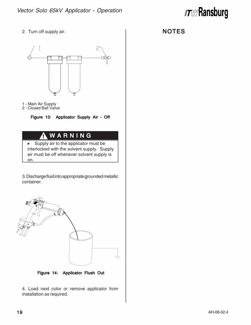
2. Turn off supply air.
3. Discharge fluid into appropriate grounded metalliccontainer.
Figure 13: Applicator Supply Air - OffFigure 13: Applicator Supply Air - OffFigure 13: Applicator Supply Air - OffFigure 13: Applicator Supply Air - OffFigure 13: Applicator Supply Air - Off
Figure 14: Applicator Flush OutFigure 14: Applicator Flush OutFigure 14: Applicator Flush OutFigure 14: Applicator Flush OutFigure 14: Applicator Flush Out
4. Load next color or remove applicator frominstallation as required.
NOTESNOTESNOTESNOTESNOTES
1 - Main Air Supply2 - Closed Ball Valve
>Supply air to the applicator must be
interlocked with the solvent supply. Supplyair must be off whenever solvent supply ison.
W A R N I N GW A R N I N GW A R N I N GW A R N I N GW A R N I N G!!!!!

AH-08-02.4
Vector Solo 65kV Applicator - Operation
2020202020
FLUID NOZZLE / AIR CAPFLUID NOZZLE / AIR CAPFLUID NOZZLE / AIR CAPFLUID NOZZLE / AIR CAPFLUID NOZZLE / AIR CAP
The fluid nozzle and air cap must be selected according to the application. The following charts showthe nozzles and air caps available for the Vector Solo.
* Material: Lacquer, 18 Sec. No. 4 Ford Cup @ 72oF. Results are material dependent.** Patterns at 8-inch target distance.
79377-44
79377-44
79552-244
FluidFluidFluidFluidFluid
NozzleNozzleNozzleNozzleNozzle
Part #Part #Part #Part #Part #
FluidFluidFluidFluidFluid
Delivery* Delivery* Delivery* Delivery* Delivery*
(ml/min)(ml/min)(ml/min)(ml/min)(ml/min)
Orif iceOrificeOrificeOrificeOrifice
IDIDIDIDID
(in/mm)(in/mm)(in/mm)(in/mm)(in/mm)
.055/1.4
.055/1.4
.055/1.4
AIR CAP / FLUID NOZZLE PERFORMANCE CHARTAIR CAP / FLUID NOZZLE PERFORMANCE CHARTAIR CAP / FLUID NOZZLE PERFORMANCE CHARTAIR CAP / FLUID NOZZLE PERFORMANCE CHARTAIR CAP / FLUID NOZZLE PERFORMANCE CHART
300
300
300
Spray TypeSpray TypeSpray TypeSpray TypeSpray Type
Air Spray
Air Spray
LVMP
A i rA i rA i rA i rA i r
C a pC a pC a pC a pC a p
79374-65
79374-98
79374-122
PatternPatternPatternPatternPattern
S ize**S ize**S ize**S ize**S ize**
( inches)( inches)( inches)( inches)( inches)
15±1/2
17±1/2
11.5±1/2
PressurePressurePressurePressurePressure
ReducerReducerReducerReducerReducer
Yellow
Yellow
Green
Appl icatorsAppl icatorsAppl icatorsAppl icatorsAppl icators
Solo
Orifice IDOrifice IDOrifice IDOrifice IDOrifice IDFluid NozzleFluid NozzleFluid NozzleFluid NozzleFluid Nozzle
Part #Part #Part #Part #Part #
79377-44
79377-144
79377-45
79377-145
79377-46
79377-146
79377-47
79377-147
79377-48
79377-48
FLUID NOZZLEFLUID NOZZLEFLUID NOZZLEFLUID NOZZLEFLUID NOZZLESELECTION CHARTSELECTION CHARTSELECTION CHARTSELECTION CHARTSELECTION CHART
Nozzle MaterialNozzle MaterialNozzle MaterialNozzle MaterialNozzle Material
1.4mm (.055-inch)
1.4mm (.055-inch)
1.8mm (.070-inch)
1.8mm (.070-inch)
1.0mm (.042-inch)
1.0mm (.042-inch)
.7mm (.028-inch)
.7mm (.028-inch)
1.2mm (.047-inch)
1.2mm (.047-inch)
Standard Wear
Extended Wear
Standard Wear
Extended Wear
Standard Wear
Extended Wear
Standard Wear
Extended Wear
Standard Wear
Extended Wear
1.4mm (.055-inch)
1.4mm (.055-inch)
1.8mm (.070-inch)
1.8mm (.070-inch)
1.0mm (.042-inch)
1.0mm (.042-inch)
.7mm (.028-inch)
.7mm (.028-inch)
1.2mm (.047-inch)
1.2mm (.047-inch)
Orifice IDOrifice IDOrifice IDOrifice IDOrifice IDFluid NozzleFluid NozzleFluid NozzleFluid NozzleFluid Nozzle
Part #Part #Part #Part #Part #
79552-244
79552-344
79552-245
79552-345
79552-246
79552-346
79552-247
79552-347
79552-248
79552-348
FLUID NOZZLE SELECTIONFLUID NOZZLE SELECTIONFLUID NOZZLE SELECTIONFLUID NOZZLE SELECTIONFLUID NOZZLE SELECTIONTRANS-TECH. CHARTTRANS-TECH. CHARTTRANS-TECH. CHARTTRANS-TECH. CHARTTRANS-TECH. CHART
Nozzle MaterialNozzle MaterialNozzle MaterialNozzle MaterialNozzle Material
Standard Wear
Extended Wear
Standard Wear
Extended Wear
Standard Wear
Extended Wear
Standard Wear
Extended Wear
Standard Wear
Extended Wear

AH-08-02.4
MAINTENANCEMAINTENANCEMAINTENANCEMAINTENANCEMAINTENANCE
Vector Solo 65kV Applicator - Maintenance
2121212121
>The user MUSTMUSTMUSTMUSTMUST read and be familiar
with the safety instructions in this manual.
>If compressed air is used in cleaning,
REMEMBER REMEMBER REMEMBER REMEMBER REMEMBER that high pressure air canbe dangerous and should NEVER NEVER NEVER NEVER NEVER beused against the body..... It can blind,deafen, and may even penetrate the skin.If used for cleaning equipment, the usershould wear safety glasses.
>ALWAYSALWAYSALWAYSALWAYSALWAYS turn the on-off lever on the
power module off prior to cleaning andservicing the equipment.
>Be SURESURESURESURESURE the power is OffOffOffOffOff and the
system is grounded before using solventto clean ANYANYANYANYANY equipment.
>DO NOT DO NOT DO NOT DO NOT DO NOT operate a faulty applicator!
>When using cleaning solvent, standard
health and safety precautions shouldapply.
>Any solvent used to clean the fluid
passages must be discharged into agrounded container. Use of ungrounded orplastic containers may cause fire orexplosion.
>Cleaning of the exterior surface of the
applicator should be done with non-polarsolvents. If cleaning requires the use ofpolar solvents, the applicator should bewiped down with non-polar solvent prior togoing back into use. Using polar solventswill leave a semi-conductive film on thesurface of the applicator that will effectefficiency of the applicator and causedamage to the components.
W A R N I N GW A R N I N GW A R N I N GW A R N I N GW A R N I N G!!!!!SUITSUITSUITSUITSUITABLE SOLABLE SOLABLE SOLABLE SOLABLE SOLVENTSVENTSVENTSVENTSVENTS
FOR CLEANING VECTORFOR CLEANING VECTORFOR CLEANING VECTORFOR CLEANING VECTORFOR CLEANING VECTOR
SOLO APPLICASOLO APPLICASOLO APPLICASOLO APPLICASOLO APPLICATTTTTORSORSORSORSORS
When cleaning the applicator, a suitable solventfor cleaning depends on the part(s) of the applicatorto be cleaned and the material that needs to beremoved. ITW Ransburg recommends that allexterior cleaning be done with non-polar solventsto prevent a conductive residue on criticalcomponents. We also understand that some ofthese solvents do not always meet the cleaningneeds of some materials. If conductive polarsolvents are used to clean the applicatorcomponents, all residue must be removed using anon-conductive non-polar solvent (i.e. high flashNaphtha). If there are any questions as to whatsolvents are best for cleaning , contact your localITW Ransburg distributor and/or your paintsupplier.
The Vector applicator, air hoses, and fluid hoseassemblies should not be submerged or soaked insolvent. However, the outer surfaces of theseitems can be wiped with a suitable cleaning solvent.The items that cannot be soaked are notedthroughout this manual. All electrical components
cannotcannotcannotcannotcannot be cleaned or soaked in any solvents.
>Use a non-polar solvent wipe as the
final cleaning sequence for cleaning allparts.
NOTENOTENOTENOTENOTE

AH-08-02.4
Vector Solo 65kV Applicator - Maintenance
2222222222
ROUTINE SCHEDULEROUTINE SCHEDULEROUTINE SCHEDULEROUTINE SCHEDULEROUTINE SCHEDULE
Follow these maintenance steps to extend thelife of the applicator and ensure efficient oper-ation:
Several TSeveral TSeveral TSeveral TSeveral Times Dailyimes Dailyimes Dailyimes Dailyimes Daily• Inspect the air cap for paint accumulation.
Clean as frequently as necessary with a softbristled brush and a suitable solvent.
• Clean all insulating surfaces in the system.Remove paint accumulation from the exteriorof the applicator with a solvent dampenedcloth.
Daily (or at start of each shift)Daily (or at start of each shift)Daily (or at start of each shift)Daily (or at start of each shift)Daily (or at start of each shift)• Verify that ALL solvent safety containers
are grounded!
• Check within 6m (20-ft.) of the point of opera-tion (of the applicator) and remove or groundALL loose or ungrounded objects.
• Inspect work holders for accumulated coat-ing materials (and remove such accumula-tions).
• Check that atomizer assembly is clean andundamaged.
>NEVERNEVERNEVERNEVERNEVER soak or submerge the electri-
cal components of the applicator, i.e., barrel,power module, or handle. Damage andfailure may occur.
C A U T I O NC A U T I O NC A U T I O NC A U T I O NC A U T I O N!!!!!
>NEVERNEVERNEVERNEVERNEVER remove the fluid nozzle as-
sembly while paint is in the applicator orpaint may enter into the air passages.Clogged or restricted air passages willcause poor atomization and/or electricalshorting. Air passages that are cloggedwith conductive material can lead to exces-sive current output levels and consequentlow operating voltage or long-term electricaldamage.
The applicator barrel MUSTMUSTMUSTMUSTMUST be tilted frontdown to remove the fluid nozzle. Failure todo so may allow paint to enter the air pas-sages, thereby reducing airflow and dam-aging the applicator barrel/cascade. Appli-cators may be flushed in lieu of tilting.However, they must be either flushed ortilted down during nozzle removal!
C A U T I O NC A U T I O NC A U T I O NC A U T I O NC A U T I O N!!!!!
• Straighten the applicator electrode if neces-sary.
• Clean the fluid filter, if used.
Electrical Output TElectrical Output TElectrical Output TElectrical Output TElectrical Output Testestestestest1. Turn the paint and/or solvent supply OFF.
>Standard electrode is "snap back"
spray wire electrode.
NOTENOTENOTENOTENOTE
>Paint and/or solvent supply must be
turned off during this test - risk of fire orexplosion.
W A R N I N GW A R N I N GW A R N I N GW A R N I N GW A R N I N G!!!!!
2. Flush the applicator (see "Flushing Proce-dure" in the "Operation" section).
3. Follow instructions for use of the 76634-00Meter.

AH-08-02.4
Vector Solo 65kV Applicator - Maintenance
2323232323
>DO NOT DO NOT DO NOT DO NOT DO NOT allow the fluid lines to stand
empty without flushing first! This will causedried paint flaking and clogging of the fluidlines, applicator passages, and/or nozzles.
C A U T I O NC A U T I O NC A U T I O NC A U T I O NC A U T I O N!!!!!
All repairs should be made on a clean, flat surface.If a vise is used to hold parts during service orrepair, DO NOT clamp onto plastic parts andalways pad the vise jaws!
The following parts should be thoroughly packedwith dielectric grease (LSCH0009-00) leaving NONONONONOair space or voids when assembling:
• All O-Rings (Teflon o-rings do not needlubrication)
• Needle Shaft Assembly
• Packing Tube
• Cascade and Barrel
Equipment RequiredEquipment RequiredEquipment RequiredEquipment RequiredEquipment Required• Special Multi-Purpose Wrench (79854-00) *
• 4mm, 3mm, and 2.5mm Allen Wrenches *
• Screwdriver (blade)
• Jam Nut Removal Tool (79793-00) *
• Dielectric Grease (LSCH0009-00) *
• Sealant, Medium Strength (7969-10)
• Dowel, 6mm (1/4") diameter
Note: * Supplied with applicator
APPLICAAPPLICAAPPLICAAPPLICAAPPLICATTTTTOR REPOR REPOR REPOR REPOR REPAIRAIRAIRAIRAIR
Figure 15: kV ProbeFigure 15: kV ProbeFigure 15: kV ProbeFigure 15: kV ProbeFigure 15: kV Probe
>There is a 10 giga ohm resistor in the
probe that lowers the output voltage. Themaximum kV rating is at no load. Paintoverspray and other contaminates on thebarrel will lower the kV probe reading.
NOTENOTENOTENOTENOTE
4. Using the meter set to kV, measure the outputvoltage of the applicator. Voltage output reading isbetween 52 and 60kV.
5. See "Troubleshooting" in the "Maintenance"section for possible cause of poor performance.
1 - Full Voltage Setting2 - 76634-00 Meter3 - 76667-00 kV Probe

AH-08-02.4
Vector Solo 65kV Applicator - Maintenance
2424242424
1. Remove applicator from the worksite afterfollowing the "Flush Procedure".
2. Remove fluid hose at base of applicator.
Figure 16: Counter-Clockwise to RemoveFigure 16: Counter-Clockwise to RemoveFigure 16: Counter-Clockwise to RemoveFigure 16: Counter-Clockwise to RemoveFigure 16: Counter-Clockwise to RemoveFluid HoseFluid HoseFluid HoseFluid HoseFluid Hose
Figure 17: Clockwise to Remove Air HoseFigure 17: Clockwise to Remove Air HoseFigure 17: Clockwise to Remove Air HoseFigure 17: Clockwise to Remove Air HoseFigure 17: Clockwise to Remove Air Hose
AIR CAPAIR CAPAIR CAPAIR CAPAIR CAP
RemovalRemovalRemovalRemovalRemoval1. While holding the barrel with one hand, loosenthe retaining nut using the other hand.
2. Unscrew the retaining nut completely andremove the air cap.
Figure 18: Air Cap RemovalFigure 18: Air Cap RemovalFigure 18: Air Cap RemovalFigure 18: Air Cap RemovalFigure 18: Air Cap Removal
Cleaning and InspectionCleaning and InspectionCleaning and InspectionCleaning and InspectionCleaning and Inspection1. Use a suitable solvent to clean the air cap.(Refer to "Suitable Solvents for Cleaning VectorSolo Applicators" in the "Maintenance" section.)
2. Examine the air cap for damage to the airhorns, face, and any air passages. If any of theseareas are damaged or worn, the air cap should bereplaced.
ReinstallReinstallReinstallReinstallReinstall1. Check the fluid nozzle to ensure that it is tightlyscrewed into the barrel.
2. Place the air cap over the electrode wire of theneedle/electrode and set it onto the fluid nozzle.
3. Place the retaining nut over the air cap andbegin screwing it onto the barrel.
4. Before securing the retainer nut to the barrel,position the air cap for the desired spray pattern.
>Ensure all pressure has been bled from
the fluid and air line prior to disconnection.
W A R N I N GW A R N I N GW A R N I N GW A R N I N GW A R N I N G!!!!!
3. Remove air hose at base of applicator.
CCW
C C W
CW CW
AH-08-02.4
Vector Solo 65kV Applicator - Maintenance
2525252525
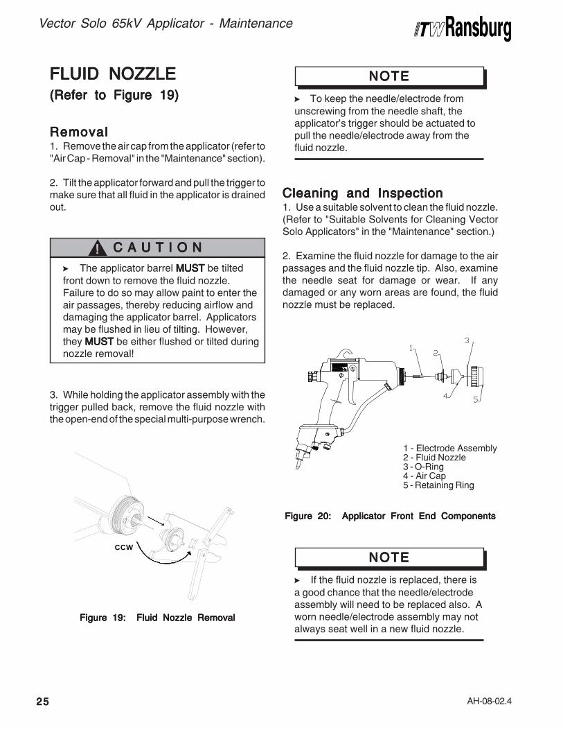
FLUID NOZZLEFLUID NOZZLEFLUID NOZZLEFLUID NOZZLEFLUID NOZZLE(Refer to Figure 19)(Refer to Figure 19)(Refer to Figure 19)(Refer to Figure 19)(Refer to Figure 19)
RemovalRemovalRemovalRemovalRemoval1. Remove the air cap from the applicator (refer to"Air Cap - Removal" in the "Maintenance" section).
2. Tilt the applicator forward and pull the trigger tomake sure that all fluid in the applicator is drainedout.
>The applicator barrel MUSTMUSTMUSTMUSTMUST be tilted
front down to remove the fluid nozzle.Failure to do so may allow paint to enter theair passages, thereby reducing airflow anddamaging the applicator barrel. Applicatorsmay be flushed in lieu of tilting. However,they MUSTMUSTMUSTMUSTMUST be either flushed or tilted duringnozzle removal!
C A U T I O NC A U T I O NC A U T I O NC A U T I O NC A U T I O N!!!!!
Figure 19: Fluid Nozzle RemovalFigure 19: Fluid Nozzle RemovalFigure 19: Fluid Nozzle RemovalFigure 19: Fluid Nozzle RemovalFigure 19: Fluid Nozzle Removal
3. While holding the applicator assembly with thetrigger pulled back, remove the fluid nozzle withthe open-end of the special multi-purpose wrench.
Figure 20: Applicator Front End ComponentsFigure 20: Applicator Front End ComponentsFigure 20: Applicator Front End ComponentsFigure 20: Applicator Front End ComponentsFigure 20: Applicator Front End Components
>To keep the needle/electrode from
unscrewing from the needle shaft, theapplicator's trigger should be actuated topull the needle/electrode away from thefluid nozzle.
NOTENOTENOTENOTENOTE
Cleaning and InspectionCleaning and InspectionCleaning and InspectionCleaning and InspectionCleaning and Inspection1. Use a suitable solvent to clean the fluid nozzle.(Refer to "Suitable Solvents for Cleaning VectorSolo Applicators" in the "Maintenance" section.)
2. Examine the fluid nozzle for damage to the airpassages and the fluid nozzle tip. Also, examinethe needle seat for damage or wear. If anydamaged or any worn areas are found, the fluidnozzle must be replaced.
>If the fluid nozzle is replaced, there is
a good chance that the needle/electrodeassembly will need to be replaced also. Aworn needle/electrode assembly may notalways seat well in a new fluid nozzle.
NOTENOTENOTENOTENOTECCW
1 - Electrode Assembly2 - Fluid Nozzle3 - O-Ring4 - Air Cap5 - Retaining Ring

AH-08-02.4
Vector Solo 65kV Applicator - Maintenance
2626262626
ReinstallReinstallReinstallReinstallReinstall1. Check the electrode tightness on the needleshaft. If it is loose, tighten it (refer to "Needle/Electrode" in the "Maintenance" section).
2. With the applicator trigger actuated, place thefluid nozzle over the needle/electrode and screwit into the barrel by hand.
3. Tighten it using the Special Multi-PurposeWrench 79854-00 with 3/8" square. Torque to 35-40 lbs•in (3.9-4.5 Nm). An alternate method (if notorque wrench is available) is to hand tighten, thentighten an additional 1/16 turn in the clockwisedirection.
4. Install the air cap and retaining ring onto theapplicator.
Figure 21: Reinstalling Fluid NozzleFigure 21: Reinstalling Fluid NozzleFigure 21: Reinstalling Fluid NozzleFigure 21: Reinstalling Fluid NozzleFigure 21: Reinstalling Fluid Nozzle
>DO NOTDO NOTDO NOTDO NOTDO NOT under-tighten the fluid
nozzle as fluid can leak into the air pas-
sages.
>DO NOTDO NOTDO NOTDO NOTDO NOTover-tighten the fluid nozzle
into the barrel. Doing so could damage orbreak the fluid nozzle or damage thethread of the barrel.
NEEDLE / ELECTRODENEEDLE / ELECTRODENEEDLE / ELECTRODENEEDLE / ELECTRODENEEDLE / ELECTRODE
RemovalRemovalRemovalRemovalRemoval1. Remove the air cap and fluid nozzle from theapplicator assembly.
2. Secure the needle shaft at the rear of the barrelwith the Special Wrench 79854-00 and unscrewthe needle/electrode from the needle shaft.
Cleaning and InspectionCleaning and InspectionCleaning and InspectionCleaning and InspectionCleaning and Inspection1. Use a suitable solvent to clean the needle/electrode.
2. Examine the needle/electrode for damage orwear. Pay special attention to the area where thewire electrode extends from the main body. Thisis a sealing surface that seats inside the fluidnozzle. If there are signs of wear in this area, boththe needle/electrode and fluid nozzle must bereplaced.
3. An electrical check of the needle/electrodemust be done prior to reinstalling it into theapplicator assembly (refer to "Needle/ElectrodeResistance Testing" in the "Maintenance" section).
ReinstallReinstallReinstallReinstallReinstall1. Secure the needle shaft at the rear of the barreland screw the needle/electrode into place byhand.
2. Reinstall the fluid nozzle and air cap onto thebarrel.
Figure 22: Electrode RemovalFigure 22: Electrode RemovalFigure 22: Electrode RemovalFigure 22: Electrode RemovalFigure 22: Electrode Removal
CW35-40LBS-IN3.9-4.5 NM
NOTENOTENOTENOTENOTE

AH-08-02.4
Vector Solo 65kV Applicator - Maintenance
2727272727
NEEDLE / ELECTRODENEEDLE / ELECTRODENEEDLE / ELECTRODENEEDLE / ELECTRODENEEDLE / ELECTRODE
RESISTRESISTRESISTRESISTRESISTANCE TESTINGANCE TESTINGANCE TESTINGANCE TESTINGANCE TESTING
The electrical resistance of the needle/electrodeshould be tested periodically (typically on a weeklybasis) or any time it is removed from the applicator.
TTTTTo To To To To Testestestestest1. Install the needle/electrode onto the front end ofan available needle shaft. Be sure that the needle/electrode is completely seated for proper contactbetween the metal shaft and the threaded insert ofthe needle/electrode.
2. Using a VOM meter that will read 15 megohmsaccurately, connect the first meter lead to themetal needle shaft and the second lead to theneedle/electrode wire. The needle/electroderesistance should be 14.5 to 19 megohms (nominal15 megohms at 9 volts or 12 to 17 megohms at1000 volts). Needle/electrodes outside theseranges must be replaced.
Figure 23: Testing Resistive ElectrodeFigure 23: Testing Resistive ElectrodeFigure 23: Testing Resistive ElectrodeFigure 23: Testing Resistive ElectrodeFigure 23: Testing Resistive Electrode
BARRELBARRELBARRELBARRELBARREL REMOV REMOV REMOV REMOV REMOVALALALALAL
1. Remove air cap and fluid nozzle.
2. Remove two (2) screws with a 3mm Allenwrench that hold the rear cover. Remove rearcover and disconnect the connector.
Figure 24: Rear Cover RemovalFigure 24: Rear Cover RemovalFigure 24: Rear Cover RemovalFigure 24: Rear Cover RemovalFigure 24: Rear Cover Removal
3, Remove the rear fluid adjustment bushing andair valve and fluid needle return springs.
Figure 25: Fluid Adjust Bushing RemovalFigure 25: Fluid Adjust Bushing RemovalFigure 25: Fluid Adjust Bushing RemovalFigure 25: Fluid Adjust Bushing RemovalFigure 25: Fluid Adjust Bushing Removal

AH-08-02.4
Vector Solo 65kV Applicator - Maintenance
2828282828
4. Remove the trigger and fluid line.
Figure 26: Fluid Line/Trigger RemovalFigure 26: Fluid Line/Trigger RemovalFigure 26: Fluid Line/Trigger RemovalFigure 26: Fluid Line/Trigger RemovalFigure 26: Fluid Line/Trigger Removal
5. Remove the two (2) jam nuts using the 79793-00 Removal Tool while holding the needle shaftwith the 79854-00 Special Wrench.
Figure 27: Jam Nut RemovalFigure 27: Jam Nut RemovalFigure 27: Jam Nut RemovalFigure 27: Jam Nut RemovalFigure 27: Jam Nut Removal
6. Remove three (3) 5mm screws using a 4mmAllen wrench. Remove the hook.
Figure 28: Barrel Screw RemovalFigure 28: Barrel Screw RemovalFigure 28: Barrel Screw RemovalFigure 28: Barrel Screw RemovalFigure 28: Barrel Screw Removal
7. Pull the barrel straight away from the handle.
Figure 29: Barrel RemovalFigure 29: Barrel RemovalFigure 29: Barrel RemovalFigure 29: Barrel RemovalFigure 29: Barrel Removal

AH-08-02.4
Vector Solo 65kV Applicator - Maintenance
2929292929
Figure 30: Cascade RemovalFigure 30: Cascade RemovalFigure 30: Cascade RemovalFigure 30: Cascade RemovalFigure 30: Cascade Removal
Remove CascadeRemove CascadeRemove CascadeRemove CascadeRemove Cascade1. Pull the cascade out of the barrel.
2. Wipe off excess dielectric lubricant.
3. Remove excess lubricant from inside barrelwith a clean cloth or rag.
Replace CascadeReplace CascadeReplace CascadeReplace CascadeReplace Cascade1. Dispense about 1/4 tube of LSCH0009-00Dielectric Grease.
Figure 31: Cascade ReplacementFigure 31: Cascade ReplacementFigure 31: Cascade ReplacementFigure 31: Cascade ReplacementFigure 31: Cascade Replacement
Reinstalling BarrelReinstalling BarrelReinstalling BarrelReinstalling BarrelReinstalling Barrel1. Replace the hook. Install the barrel against thehandle and hand tighten two (2) long 5mm screws,in an alternating sequence with the 4mm Allenwrench. Tighten the hook screw with the same4mm wrench.
2. Install the first jam nut. Tighten to stop by handwhile holding the needle shaft.
Figure 33: First Jam Nut ReplacementFigure 33: First Jam Nut ReplacementFigure 33: First Jam Nut ReplacementFigure 33: First Jam Nut ReplacementFigure 33: First Jam Nut Replacement
Figure 32: Installing Barrel to HandleFigure 32: Installing Barrel to HandleFigure 32: Installing Barrel to HandleFigure 32: Installing Barrel to HandleFigure 32: Installing Barrel to Handle
inside the barrel and on the sides of the cascade.2. Slide the cascade back into the barrel.
>Failure to use the LSCH0009-00 may
shorten product life.
C A U T I O NC A U T I O NC A U T I O NC A U T I O NC A U T I O N!!!!!
1 - 79793 Removal Tool2 - 1st Jam Nut3 - 79854 Special Wrench4 - 2nd Jam Nut (Raised Center)

AH-08-02.4
Vector Solo 65kV Applicator - Maintenance
3030303030
Figure 34: Second Jam Nut ReplacementFigure 34: Second Jam Nut ReplacementFigure 34: Second Jam Nut ReplacementFigure 34: Second Jam Nut ReplacementFigure 34: Second Jam Nut Replacement
3. Tighten second jam nut with raised centerfacing out, while holding the needle shaft.
Figure 37: Rear Cover ReplacementFigure 37: Rear Cover ReplacementFigure 37: Rear Cover ReplacementFigure 37: Rear Cover ReplacementFigure 37: Rear Cover Replacement
4. Install the fluid adjustment assembly along withthe air and fluid return springs.
Figure 36: Fluid Line/Trigger InstallationFigure 36: Fluid Line/Trigger InstallationFigure 36: Fluid Line/Trigger InstallationFigure 36: Fluid Line/Trigger InstallationFigure 36: Fluid Line/Trigger Installation
Figure 35: Spring and Fluid Adjust ValveFigure 35: Spring and Fluid Adjust ValveFigure 35: Spring and Fluid Adjust ValveFigure 35: Spring and Fluid Adjust ValveFigure 35: Spring and Fluid Adjust ValveReplacementReplacementReplacementReplacementReplacement
5. Install trigger and fluid line and torque fluidtube fittings 40-45 lbs-in.
6. Reconnect the rear cover and install with two(2) 4mm screws.
1 - Fluid Return Spring2 - Fluid Adjustment Valve3 - Air Valve Return Spring
AH-08-02.4
Vector Solo 65kV Applicator - Maintenance
3131313131
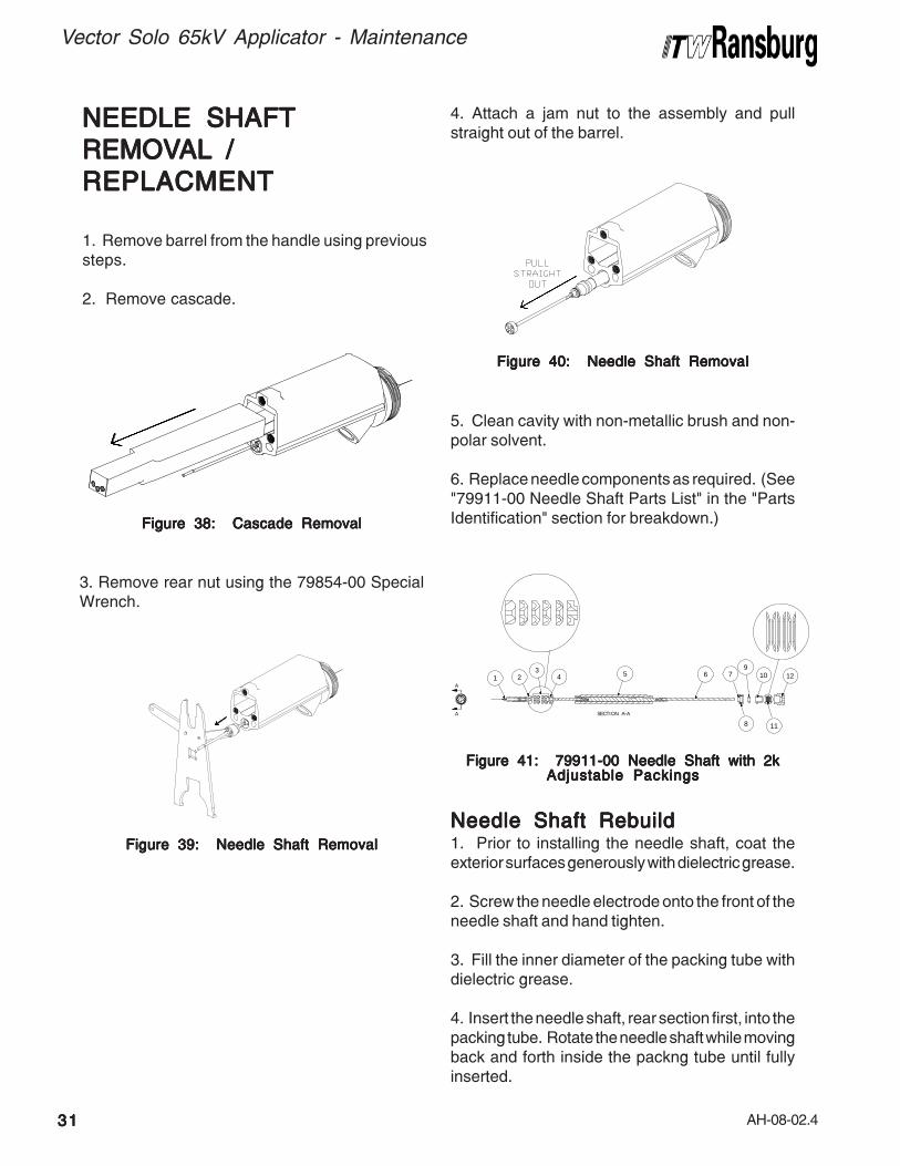
Figure 39: Needle Shaft RemovalFigure 39: Needle Shaft RemovalFigure 39: Needle Shaft RemovalFigure 39: Needle Shaft RemovalFigure 39: Needle Shaft Removal
3. Remove rear nut using the 79854-00 SpecialWrench.
Figure 40: Needle Shaft RemovalFigure 40: Needle Shaft RemovalFigure 40: Needle Shaft RemovalFigure 40: Needle Shaft RemovalFigure 40: Needle Shaft Removal
4. Attach a jam nut to the assembly and pullstraight out of the barrel.
Figure 41: 79911-00 Needle Shaft with 2kFigure 41: 79911-00 Needle Shaft with 2kFigure 41: 79911-00 Needle Shaft with 2kFigure 41: 79911-00 Needle Shaft with 2kFigure 41: 79911-00 Needle Shaft with 2kAdjustable PackingsAdjustable PackingsAdjustable PackingsAdjustable PackingsAdjustable Packings
5. Clean cavity with non-metallic brush and non-polar solvent.
6. Replace needle components as required. (See"79911-00 Needle Shaft Parts List" in the "PartsIdentification" section for breakdown.)
Needle Shaft RebuildNeedle Shaft RebuildNeedle Shaft RebuildNeedle Shaft RebuildNeedle Shaft Rebuild1. Prior to installing the needle shaft, coat theexterior surfaces generously with dielectric grease.
2. Screw the needle electrode onto the front of theneedle shaft and hand tighten.
3. Fill the inner diameter of the packing tube withdielectric grease.
4. Insert the needle shaft, rear section first, into thepacking tube. Rotate the needle shaft while movingback and forth inside the packng tube until fullyinserted.
NEEDLE SHAFTNEEDLE SHAFTNEEDLE SHAFTNEEDLE SHAFTNEEDLE SHAFT
REMOVREMOVREMOVREMOVREMOVALALALALAL / / / / /
REPLACMENTREPLACMENTREPLACMENTREPLACMENTREPLACMENT
1. Remove barrel from the handle using previoussteps.
2. Remove cascade.
Figure 38: Cascade RemovalFigure 38: Cascade RemovalFigure 38: Cascade RemovalFigure 38: Cascade RemovalFigure 38: Cascade Removal
A
A
SECTION A-A
23
4 5 6
8
79
10 121
11

AH-08-02.4
Vector Solo 65kV Applicator - Maintenance
3232323232
2. Tighten rear nut using Special Wrench 79854-00. Tighten until drag is felt on the shaft when it ispushed back and forth.
Figure 43: Adjustable Needle ShaftFigure 43: Adjustable Needle ShaftFigure 43: Adjustable Needle ShaftFigure 43: Adjustable Needle ShaftFigure 43: Adjustable Needle Shaft
Reinstall Needle Shaft / BarrelReinstall Needle Shaft / BarrelReinstall Needle Shaft / BarrelReinstall Needle Shaft / BarrelReinstall Needle Shaft / Barrel1. Push needle shaft assembly straight into thebarrel.
Figure 42: Needle Shaft ReplacementFigure 42: Needle Shaft ReplacementFigure 42: Needle Shaft ReplacementFigure 42: Needle Shaft ReplacementFigure 42: Needle Shaft Replacement
Figure 45: Power Module RemovalFigure 45: Power Module RemovalFigure 45: Power Module RemovalFigure 45: Power Module RemovalFigure 45: Power Module Removal
3. Reinstall cascade.
4. Reinstall barrel to handle.
Power Module RemovalPower Module RemovalPower Module RemovalPower Module RemovalPower Module Removal1. Remove the fluid line
Figure 44: Fluid Line RemovalFigure 44: Fluid Line RemovalFigure 44: Fluid Line RemovalFigure 44: Fluid Line RemovalFigure 44: Fluid Line Removal
>Be generous with the dielectric grease
when applying it to the packing tube andneedle shaft. This helps to remove airvoids from this chamber. DO NOTDO NOTDO NOTDO NOTDO NOT applyso much grease that it creates an air lockduring assembly of the applicator.
NOTENOTENOTENOTENOTE
5. With your finger, wipe the excess grease fromboth ends of the packing tube. Using the excessgrease, apply a thin film to the outer surface of thepacking tube and to the external o-ring on thecartridge seal.
6. Apply a light film of dielectric grease to the sealretainer o-ring and install it into the external groove.
2. Remove three (3) bolts using a 3mm Allenwrench.

AH-08-02.4
Vector Solo 65kV Applicator - Maintenance
3333333333
4. Remove the rear seal.
Figure 48: Rear Seal RemovalFigure 48: Rear Seal RemovalFigure 48: Rear Seal RemovalFigure 48: Rear Seal RemovalFigure 48: Rear Seal Removal
5. Using a dowel rod, push out the air valvecartridge.
Figure 49: Air Valve Cartridge RemovalFigure 49: Air Valve Cartridge RemovalFigure 49: Air Valve Cartridge RemovalFigure 49: Air Valve Cartridge RemovalFigure 49: Air Valve Cartridge Removal
Figure 47: Air Valve RemovalFigure 47: Air Valve RemovalFigure 47: Air Valve RemovalFigure 47: Air Valve RemovalFigure 47: Air Valve Removal
Handle DisassemblyHandle DisassemblyHandle DisassemblyHandle DisassemblyHandle Disassembly1. Remove barrel.
2. Remove power module.
3. Push air valve out.
Figure 46: Power Module RemovalFigure 46: Power Module RemovalFigure 46: Power Module RemovalFigure 46: Power Module RemovalFigure 46: Power Module Removal
>The power modules are not service-
able.
NOTENOTENOTENOTENOTE
1 - Push Out From Here1 - Push Out From Here1 - Push Out From Here1 - Push Out From Here1 - Push Out From Here
1 - 6mm (1/4") Dowel1 - 6mm (1/4") Dowel1 - 6mm (1/4") Dowel1 - 6mm (1/4") Dowel1 - 6mm (1/4") Dowel
3. Pull the module straight off the handle.

AH-08-02.4
Vector Solo 65kV Applicator - Maintenance
3434343434
6. Remove air valve cartridge seal (black) (seeFigure 48).
7. Remove front air valve seal (white).
Figure 50: Air Valve Cartridge Seal and FrontFigure 50: Air Valve Cartridge Seal and FrontFigure 50: Air Valve Cartridge Seal and FrontFigure 50: Air Valve Cartridge Seal and FrontFigure 50: Air Valve Cartridge Seal and Front
Seal RemovalSeal RemovalSeal RemovalSeal RemovalSeal Removal
Figure 52: Cartridge Seal ReplacementFigure 52: Cartridge Seal ReplacementFigure 52: Cartridge Seal ReplacementFigure 52: Cartridge Seal ReplacementFigure 52: Cartridge Seal Replacement
2. Install the air valve cartridge seal.
Figure 51: Air Valve Seal ReplacementFigure 51: Air Valve Seal ReplacementFigure 51: Air Valve Seal ReplacementFigure 51: Air Valve Seal ReplacementFigure 51: Air Valve Seal Replacement
>If you remove the air valve seal, it is
highly recommended that it is replaced.
NOTENOTENOTENOTENOTE
Handle RebuildHandle RebuildHandle RebuildHandle RebuildHandle Rebuild1. Install the front air valve seal using the SpecialTool.
1 - Rear Seal1 - Rear Seal1 - Rear Seal1 - Rear Seal1 - Rear Seal2 - Air Valve Cartridge Seal2 - Air Valve Cartridge Seal2 - Air Valve Cartridge Seal2 - Air Valve Cartridge Seal2 - Air Valve Cartridge Seal3 - Front Air Valve Seal3 - Front Air Valve Seal3 - Front Air Valve Seal3 - Front Air Valve Seal3 - Front Air Valve Seal
1 - 79793-00 Jam Nut Tool1 - 79793-00 Jam Nut Tool1 - 79793-00 Jam Nut Tool1 - 79793-00 Jam Nut Tool1 - 79793-00 Jam Nut Tool2 - Front Air Valve Seal - Concave Side to Tool2 - Front Air Valve Seal - Concave Side to Tool2 - Front Air Valve Seal - Concave Side to Tool2 - Front Air Valve Seal - Concave Side to Tool2 - Front Air Valve Seal - Concave Side to Tool
>Only remove the front air valve seal
(item 3) if there is damage or wear to theseal causing leakage.
NOTENOTENOTENOTENOTE

AH-08-02.4
Vector Solo 65kV Applicator - Maintenance
3535353535
Figure 57: Fluid Fitting RemovalFigure 57: Fluid Fitting RemovalFigure 57: Fluid Fitting RemovalFigure 57: Fluid Fitting RemovalFigure 57: Fluid Fitting Removal
Power Module - Fluid FittingPower Module - Fluid FittingPower Module - Fluid FittingPower Module - Fluid FittingPower Module - Fluid Fitting
RemovalRemovalRemovalRemovalRemoval1. Remove power module from handle.
4. Install the rear seal.
5. Install air valve.
Figure 54: Rear Cartridge Seal ReplacementFigure 54: Rear Cartridge Seal ReplacementFigure 54: Rear Cartridge Seal ReplacementFigure 54: Rear Cartridge Seal ReplacementFigure 54: Rear Cartridge Seal Replacement
Figure 55: Air Valve ReplacementFigure 55: Air Valve ReplacementFigure 55: Air Valve ReplacementFigure 55: Air Valve ReplacementFigure 55: Air Valve Replacement
Figure 56: Power Module RemovalFigure 56: Power Module RemovalFigure 56: Power Module RemovalFigure 56: Power Module RemovalFigure 56: Power Module Removal
2. Remove two (2) screws using a 2.5mm Allenwrench.
Figure 53: Air Valve Cartridge AlignmentFigure 53: Air Valve Cartridge AlignmentFigure 53: Air Valve Cartridge AlignmentFigure 53: Air Valve Cartridge AlignmentFigure 53: Air Valve Cartridge Alignment
3. Install the air valve cartridge. Align the cartridgewith tab at 12 o'clock posiition.
6. Reinstall barrel.
7. Install power module.

AH-08-02.4
Vector Solo 65kV Applicator - Maintenance
3636363636
3. Install the 1/4 module into the 3/4 module andtighten the two (2) screws.
Figure 61: Module AssemblyFigure 61: Module AssemblyFigure 61: Module AssemblyFigure 61: Module AssemblyFigure 61: Module Assembly
4. Install power module to handle and tighten three(3) screws. Reinstall the fluid line and torque fluidtube fittings to 40-45 lbs-in.
3. Remove the 1/4 module from the 3/4 module.Pull the fluid fitting out.
Figure 58: Fluid Fitting RemovalFigure 58: Fluid Fitting RemovalFigure 58: Fluid Fitting RemovalFigure 58: Fluid Fitting RemovalFigure 58: Fluid Fitting Removal
2. Install the fluid fitting.
Figure 60: Fluid Fitting ReplacementFigure 60: Fluid Fitting ReplacementFigure 60: Fluid Fitting ReplacementFigure 60: Fluid Fitting ReplacementFigure 60: Fluid Fitting Replacement
Figure 59: Ground Clip ReplacementFigure 59: Ground Clip ReplacementFigure 59: Ground Clip ReplacementFigure 59: Ground Clip ReplacementFigure 59: Ground Clip Replacement
Fitting ReplacementFitting ReplacementFitting ReplacementFitting ReplacementFitting Replacement1. Ensure the ground clip is properly installed.Tabs must be touching the air and fluid fitting.
Figure 62: Power Module AssemblyFigure 62: Power Module AssemblyFigure 62: Power Module AssemblyFigure 62: Power Module AssemblyFigure 62: Power Module Assembly
>The ground clip must be properly
installed such that it touches both the airand fluid fitting.
W A R N I N GW A R N I N GW A R N I N GW A R N I N GW A R N I N G!!!!!

AH-08-02.4
Vector Solo 65kV Applicator - Maintenance
3737373737
TEST ANDTEST ANDTEST ANDTEST ANDTEST AND
MAINTENANCE KITMAINTENANCE KITMAINTENANCE KITMAINTENANCE KITMAINTENANCE KIT
USAGE (79870-00)USAGE (79870-00)USAGE (79870-00)USAGE (79870-00)USAGE (79870-00)
Figure 63: 79870 Test and Maintenance KitFigure 63: 79870 Test and Maintenance KitFigure 63: 79870 Test and Maintenance KitFigure 63: 79870 Test and Maintenance KitFigure 63: 79870 Test and Maintenance Kit
3
6
5
2
4
1
123456
79870 TEST AND79870 TEST AND79870 TEST AND79870 TEST AND79870 TEST AND
MAINTENANCE KITMAINTENANCE KITMAINTENANCE KITMAINTENANCE KITMAINTENANCE KIT
Item# Item# Item# Item# Item#
Brass Tee Fitting100 psi Pressure Gauge6" Air Hose AssemblyLeft Hand Male FittingBarb FittingTubing
Description Description Description Description Description
The 79870 Test and Maintenance Kit allows theuser to determine the inlet pressure at the base(handle) of the Vector Solo hand-held applicators.The Test and Maintenance Kit also allows the userto test the 79835 Power Module Assembly on theVector Solo applicator.
The procedure to test the inlet pressure at thebase (handle) of the Vector Solo applicator is asfollows (see Figures 63 and 64):
1. Connect the left-hand fitting of the 79727 AirHose to the male inlet of the Test and MaintenanceKit.
2. Connect the 6" air hose assembly between thebrass tee fitting and the gun air inlet.
3. Connect the other end of the air hose to theregulated air supply.
4. Turn on main air. Trigger the applicator with kVswitch on high (down position). Read the pressureat the 100 psi pressure gauge. This pressureshould be at least 40 psi with air flowing for properfunctioning of the Vector Solo applicator.
Figure 64: Testing the Pressure at the BaseFigure 64: Testing the Pressure at the BaseFigure 64: Testing the Pressure at the BaseFigure 64: Testing the Pressure at the BaseFigure 64: Testing the Pressure at the Base(Handle) of the Applicator(Handle) of the Applicator(Handle) of the Applicator(Handle) of the Applicator(Handle) of the Applicator

AH-08-02.4
Vector Solo 65kV Applicator - Maintenance
3838383838
The procedure to test the 79835 Power ModuleAssembly is as follows:
1. Remove the 79835 Power Module Assemblyfrom the handle.2. Connect the barb fitting [5] to the brass teefitting [1]. Place the tubing [6] on the end of thebarb fitting.
Figure 65: Remove Power Module fromFigure 65: Remove Power Module fromFigure 65: Remove Power Module fromFigure 65: Remove Power Module fromFigure 65: Remove Power Module fromHandleHandleHandleHandleHandle
6
1 LH5
Figure 66: Connect Barb and Tubing toFigure 66: Connect Barb and Tubing toFigure 66: Connect Barb and Tubing toFigure 66: Connect Barb and Tubing toFigure 66: Connect Barb and Tubing toTee FittingTee FittingTee FittingTee FittingTee Fitting
3. Connect the left-hand fitting of the 79727 AirHose to the male inlet of the Test and MaintenanceKit.
4. Insert the tubing [6] into the smaller diameterhole in the top of the air fitting in the power module.
Figure 67: Connect Tubing to the Air FittingFigure 67: Connect Tubing to the Air FittingFigure 67: Connect Tubing to the Air FittingFigure 67: Connect Tubing to the Air FittingFigure 67: Connect Tubing to the Air Fitting
6
TP-1TP-2
Figure 68: Connect the PC Board to a DigitalFigure 68: Connect the PC Board to a DigitalFigure 68: Connect the PC Board to a DigitalFigure 68: Connect the PC Board to a DigitalFigure 68: Connect the PC Board to a DigitalMulti-Meter and True Earth GroundMulti-Meter and True Earth GroundMulti-Meter and True Earth GroundMulti-Meter and True Earth GroundMulti-Meter and True Earth Ground
5. Connect a wire from test point 2 (on the PCboard in the power module) to a true earth ground.
6. Connect a digital multi-meter to test points 1and 2.
TP-1-Test Point #1 TP-2-Test Point #2 Ground-True Earth

AH-08-02.4
Vector Solo 65kV Applicator - Maintenance
3939393939
7. Connect the 79727 Air Hose to main air.
8. Turn on main air and set the pressure so thepressure gauge [2] in the 79870 Test andMaintenance Kit reads 25 psi (1.7 bar). The voltagekV setpoint lever should be in the high voltageposition (down). The digital multi-meter shouldread approximately 15 VDC.
TP-1TP-2
1.7 BAR(25 PSIG )
Figure 69: Set Pressure Gauge toFigure 69: Set Pressure Gauge toFigure 69: Set Pressure Gauge toFigure 69: Set Pressure Gauge toFigure 69: Set Pressure Gauge to 1.7 BAR(25 psig) 1.7 BAR(25 psig) 1.7 BAR(25 psig) 1.7 BAR(25 psig) 1.7 BAR(25 psig)
9. If the voltage is outside this range, there is aproblem with the power module circuitry. If thevoltage range is acceptable the power module isoperating correctly, and there is an issue witheither the cascade or the wire connections leadingto it.
AIR HOSEAIR HOSEAIR HOSEAIR HOSEAIR HOSE
MAINTENANCEMAINTENANCEMAINTENANCEMAINTENANCEMAINTENANCE
Air Hose -Ground Wire EndAir Hose -Ground Wire EndAir Hose -Ground Wire EndAir Hose -Ground Wire EndAir Hose -Ground Wire End1. Cut the end of the air hose so that end is square.
2. Slide the sleeve and compression ring onto theair hose end.
Figure 70: Sleeve and Compression RingFigure 70: Sleeve and Compression RingFigure 70: Sleeve and Compression RingFigure 70: Sleeve and Compression RingFigure 70: Sleeve and Compression Ring
3. Push the stem of the fitting all the way into theinto the air hose.
4. Slide the compression ring and the sleeve intothe fitting body and tighten.
Air Hose -Applicator EndAir Hose -Applicator EndAir Hose -Applicator EndAir Hose -Applicator EndAir Hose -Applicator End 1. Cut the end of the air hose so that end issquare.
2.Install the 79930 fitting (std) or 79868 (qd) intothe hose end. Lightly lubricate the barb end ofthe fitting with LSCH-0009 di-electric lubricant.Push the fitting into the air hose up to the
threads on the stem.
Figure 71: Ground Fitting InsertionFigure 71: Ground Fitting InsertionFigure 71: Ground Fitting InsertionFigure 71: Ground Fitting InsertionFigure 71: Ground Fitting Insertion
Figure 72: Sleeve TighteningFigure 72: Sleeve TighteningFigure 72: Sleeve TighteningFigure 72: Sleeve TighteningFigure 72: Sleeve Tightening
Figure 73: Fitting InsertionFigure 73: Fitting InsertionFigure 73: Fitting InsertionFigure 73: Fitting InsertionFigure 73: Fitting Insertion

AH-08-02.4
Vector Solo 65kV Applicator - Maintenance
4040404040
3. With the 79330 fitting, hold the hose in one handand press a 6mm or 1/4" t-handle allen wrench intothe hex in the part while turning clockwise. Tightentill cap is approximately .8 mm (1/32") from theswivel nut.
Resistance TResistance TResistance TResistance TResistance Testestestestest1. If the hose is changed, the resistance must bechecked. Using a Meg Ohm meter at 1000Vmeasure the resistance from the lug of the groundwire to the body of the QD (79868) or the swivel nut(79930). The reading must be less than .5 MegaOhms resistance end to end.
0.8mm (1/32")
Figure 74: Tightening 79930 FittingFigure 74: Tightening 79930 FittingFigure 74: Tightening 79930 FittingFigure 74: Tightening 79930 FittingFigure 74: Tightening 79930 Fitting
4. With the 79868 DQ fitting, hold the hose in onehand and press against a firm surface whileturning the body wrench flat clockwise. Tighten tillcap is approximately .8 mm (1/32") from the QDbase.
0 .8m m (1 /32")
Figure 75: Tightening 79868 QD FittingFigure 75: Tightening 79868 QD FittingFigure 75: Tightening 79868 QD FittingFigure 75: Tightening 79868 QD FittingFigure 75: Tightening 79868 QD Fitting
Figure 76: Air Hose Resistance TestFigure 76: Air Hose Resistance TestFigure 76: Air Hose Resistance TestFigure 76: Air Hose Resistance TestFigure 76: Air Hose Resistance Test

AH-08-02.4
Vector Solo 65kV Applicator - Maintenance
TROUBLESHOOTING GUIDETROUBLESHOOTING GUIDETROUBLESHOOTING GUIDETROUBLESHOOTING GUIDETROUBLESHOOTING GUIDE
1. On-Off lever in wrong position
2. Low pressure
3. No ground connection
4. Cascade not functioning
5. Three (3) screws at base of handleare loose
6. Failed power module
1. Fluid remnants in the air passage
2. Wrong solvent used for final clean-ing process
3. Add sufficient air pressure at handle
1. No pressure
2. Fluid tube may be plugged
3. Fluid nozzle may be plugged
4. Electrode not properly assembled
5. Material too viscous
1. No adjustment of fan pattern
2. Poor atomization
3. Fluid in air passages
1. Ensure the On/Off lever is in theOn position.
2. Ensure 40 psig (2.75 bar) at theapplicator handle with applicatortriggered.
3. Ensure the air hose is properlygrounded to the earth ground.
4. Ensure cascade is functioning prop-erly.
5. Tighten screws to ensure properassembly.
6. Ensure module is properly functioning.
1a. Clean air passages with non-polarsolvent.
1b. Ensure fluid nozzle is properlytightened.
2. Use non-polar solvent for the finalcleaning process.
3. Ensure 2.8 bar (40 psig) at the handlewith applicator triggered.
1. Ensure pressure at the fluid line at theapplicator.
2. Replace or clean.
3. Replace or clean.
4. Reassemble tightened to stop.
5. Thin the material to a viscosity that issprayable.
1a. Restrictor left out of barrel.1b. The three (3) 5mm barrel to handle
screws are not properly tightened.2. Ensure atomization air passages are
clear of all foreign particles.3.Ensure fluid nozzle is properly tight-
ened.
General ProblemGeneral ProblemGeneral ProblemGeneral ProblemGeneral Problem Possible CausePossible CausePossible CausePossible CausePossible Cause SolutionSolutionSolutionSolutionSolution
INADEQUATE DELIVERYINADEQUATE DELIVERYINADEQUATE DELIVERYINADEQUATE DELIVERYINADEQUATE DELIVERY
ELECTRICALELECTRICALELECTRICALELECTRICALELECTRICAL
No kVNo kVNo kVNo kVNo kV
Low kVLow kVLow kVLow kVLow kV
No Fluid FlowNo Fluid FlowNo Fluid FlowNo Fluid FlowNo Fluid Flow
Spray Performance Spray Performance Spray Performance Spray Performance Spray Performance
4141414141

AH-08-02.4
PPPPPARARARARARTS IDENTIFICATS IDENTIFICATS IDENTIFICATS IDENTIFICATS IDENTIFICATIONTIONTIONTIONTION
Figure 77: Vector Solo 65kV Applicator Parts BreakdownFigure 77: Vector Solo 65kV Applicator Parts BreakdownFigure 77: Vector Solo 65kV Applicator Parts BreakdownFigure 77: Vector Solo 65kV Applicator Parts BreakdownFigure 77: Vector Solo 65kV Applicator Parts Breakdown
Vector Solo 65kV Applicator - Parts Identification
4242424242

AH-08-02.4
Vector Solo 65kV Applicator - Parts Identification
4343434343
(Continued On Next Page)(Continued On Next Page)(Continued On Next Page)(Continued On Next Page)(Continued On Next Page)
1 Table D-"D2"Table D-"D2"Table D-"D2"Table D-"D2"Table D-"D2" Nozzle, Fluid 12 79906-00 Assembly, Barrel, Vector Solo 13 79907-00 Cascade Assembly 14 79832-00 Gasket, Barrel 15 79881-00 Gasket, Exhaust, Wrap-Around 16 Table D-"D1"Table D-"D1"Table D-"D1"Table D-"D1"Table D-"D1" Cap, Air 17 79724-00 Nut, Retaining, Air Nozzle 18 LSOR0005-17 O-Ring, Teflon Encapsulated 19 79385-00 Nut, Connector, Hose 210 EMF-202-05 Ferrule, Back 3/8" Tube 211 EMF-203-05 Ferrule, Front 3/8" Tube 212 79878-12 Tube, Fluid Inlet, 3.2mm ID (.125") (Accessory) 1
79878-13 Tube, Fluid Inlet, 3.4mm ID (.250") (Accessory) 1
Table E-"E"Table E-"E"Table E-"E"Table E-"E"Table E-"E" Tube, Fluid 113 79816-00 Assembly, Rear Cover 114 79798-03 SHCS, M5 X 30" 115 79799-01 Socket Head Cap Screw, M4 X 25mm 416 79798-02 Socket Head Cap Screw, M5 X 80mm 217 Table C-"C"Table C-"C"Table C-"C"Table C-"C"Table C-"C" Assembly, Trigger 118 79454-00 Screw, Trigger Retention 219 79768-00 Nut, Fluid Jam, Front 120 79774-00 Spring, Air Valve Return 121 79701-00 Hook, Molded 122 79799-02 SHCS, M4 X 30mm 123 Table A-"A"Table A-"A"Table A-"A"Table A-"A"Table A-"A" Assembly, Air Hose, Solo (10, 20, and 30m Lengths) 124 79833-02 Assembly, Handle, Vector Solo 1
(Includes Items 33, 34, 35, 36, 37, and 38)24A 79833-03 Assembly, Handle Only 125 79835-00 Assembly, Power Module 1
(Includes Items 39, 40, 41, 42, and 43)26 79768-00 Nut, Fluid Jam, Spring Guide 127 78636-00 Spring 128 79789-00 Assembly, Rear Fluid Adjustment 129 79781-00 Seal, Adjustment Bushing 130 79837-00 Gasket, Handle to Power Module 131 Table D-"D3"Table D-"D3"Table D-"D3"Table D-"D3"Table D-"D3" Pressure Reducer, Atomizing Air 132 79911-00 Kit, Shaft Assembly, 2-Piece Needle, Vector Solo 133 79760-00 Seal, Air Valve 134 79769-00 Seal, Air Cartridge 135 79770-00 Cartridge, Air Valve 136 79759-00 Assembly, Fan Air Adjust Valve 137 79772-00 Assembly, Air Valve 138 79847-00 Valve, Atom Adjust 1
79847-01 Plug, Atom (Std. installed in applicator) 139 79755-00 Fluid Inlet 140 79814-00 SHCS, M4 X 20mm 141 79836-00 Gasket, Exhaust 142 79805-00 Screw 343 79843-00 Assembly, Exhaust Housing 1
Item #Item #Item #Item #Item #
VECTVECTVECTVECTVECTOR SOLO 65kV SOLOR SOLO 65kV SOLOR SOLO 65kV SOLOR SOLO 65kV SOLOR SOLO 65kV SOLVENTBORNE APPLICAVENTBORNE APPLICAVENTBORNE APPLICAVENTBORNE APPLICAVENTBORNE APPLICATTTTTOR -OR -OR -OR -OR -PPPPPARARARARARTS LISTTS LISTTS LISTTS LISTTS LIST (Figure 77) (Figure 77) (Figure 77) (Figure 77) (Figure 77)
Part #Part #Part #Part #Part # DescriptionDescriptionDescriptionDescriptionDescription Q t yQ t yQ t yQ t yQ t y

AH-08-02.4
Vector Solo 65kV Applicator - Parts Identification
4444444444
79965 - A B C D E
1 = 10m (33 ft.) Standard Air Hose2 = 15m (49 ft.) Standard Air Hose3 = 20m (60 ft.) Standard Air Hose4 = 30m (99 ft.) Standard Air Hose5 = 10m (33 ft.) QD Air Hose6 = 15m (49 ft.) QD Air Hose7 = 20m (60 ft.) QD Air Hose8 = 30m (99 ft.) QD Air Hose
1 = Standard Fluid Tube, .093" ID2 = Coiled Fluid Tube, 1/8" ID3 = Fluid Tube, 1/8" ID4 = Fluid Tube, 1/4" ID
0 = Standard Spray, 65kV AirCap, 1.4mm Fluid Nozzle, #44
1 = Standard Spray, 65kV AirCap, 1.8mm Fluid Nozzle, #45
2 = Trans-Tech.. 122V AirCap, 1.8mm Fluid Nozzle, #245
3 = Round Spray4 = Standard Spray, 65kV Air
Cap, 1.2mm Fluid Nozzle, #48
0 = No Fluid Hose1 = Fluid Hose, 10m (33 ft.)2 = Fluid Hose, 15m (49 ft.)3 = Fluid Hose, 20m (60 ft.)4 = Fluid Hose, 30m (99 ft.)
2 = Two-Finger Trigger
VECTVECTVECTVECTVECTOR SOLO RS70-AS MODELOR SOLO RS70-AS MODELOR SOLO RS70-AS MODELOR SOLO RS70-AS MODELOR SOLO RS70-AS MODEL IDENTIFICA IDENTIFICA IDENTIFICA IDENTIFICA IDENTIFICATIONTIONTIONTIONTION
44 79861-00 Hose, Exhaust 145 79793-00 Jam Nut Removal/Seal Install Tool 146 79854-00 Wrench, Vector Solo 1
(Packing Adjust, Barrel Removal, Nozzle Removal)47 79862-01, -02, -03 Hex Driver (2.5mm, 3mm, and 4mm) 148 79529-00-K5 Applicator Cover 149 LSCH0009-00 Dielectric Grease 150 79869-00 Stem, Male QD (Included with QD Ordered Models) 1
Item #Item #Item #Item #Item #
VECTVECTVECTVECTVECTOR SOLO 65KV SOLOR SOLO 65KV SOLOR SOLO 65KV SOLOR SOLO 65KV SOLOR SOLO 65KV SOLVENTBORNE APPLICAVENTBORNE APPLICAVENTBORNE APPLICAVENTBORNE APPLICAVENTBORNE APPLICATTTTTOR -OR -OR -OR -OR -PPPPPARARARARARTS LISTTS LISTTS LISTTS LISTTS LIST (Cont.) (Figure 77) (Cont.) (Figure 77) (Cont.) (Figure 77) (Cont.) (Figure 77) (Cont.) (Figure 77)
Part #Part #Part #Part #Part # DescriptionDescriptionDescriptionDescriptionDescription Q t yQ t yQ t yQ t yQ t y

AH-08-02.4
Vector Solo 65kV Applicator - Parts Identification
4545454545
2 2-Finger Trigger 79787-00
CCCCC
Dash #Dash #Dash #Dash #Dash #
TTTTTABLE C - TRIGGER SELECTIONABLE C - TRIGGER SELECTIONABLE C - TRIGGER SELECTIONABLE C - TRIGGER SELECTIONABLE C - TRIGGER SELECTION
"C""C""C""C""C"DescriptionDescriptionDescriptionDescriptionDescription
1 Standard Fluid Tube, .093" ID X 3/8" OD 79878-112 Coil Fluid Hose, .125" ID, Low Flow 79871-013 Standard Fluid Tube, 1/8" ID X 3/8" OD 79878-124 Standard Fluid Tube, 1/4" ID X 3/8" OD 79878-13
BBBBB
Dash #Dash #Dash #Dash #Dash #
TTTTTABLE B - FLUID TUBE SELECTIONABLE B - FLUID TUBE SELECTIONABLE B - FLUID TUBE SELECTIONABLE B - FLUID TUBE SELECTIONABLE B - FLUID TUBE SELECTION
"B""B""B""B""B"DescriptionDescriptionDescriptionDescriptionDescription
10m (33-ft.)
15m (49-ft.)
20m (66-ft.)
30m (99-ft.)
DescriptionDescriptionDescriptionDescriptionDescription"A""A""A""A""A"
Dash #Dash #Dash #Dash #Dash #
79727-10 / ---------
79727-15 / ---------
79727-20 / ---------
79727-30 / ---------
79727-11/ 79869-00
79727-16 / 79869-00
79727-21/ 79869-00
79727-31/ 79869-00
"A""A""A""A""A"Air HAir HAir HAir HAir H ose/ose/ose/ose/ose/
StemStemStemStemStem
Standard Air Hose
Standard Air Hose
Standard Air Hose
Standard Air Hose
Air Hose W/Quick-Disconnect / QD Stem
Air Hose W/Quick-Disconnect / QD Stem
Air Hose W/Quick-Disconnect / QD Stem
Air Hose W/Quick-Disconnect / QD Stem
DescriptionDescriptionDescriptionDescriptionDescription
TTTTTABLE AABLE AABLE AABLE AABLE A - Air Hose Length and Air Hose T - Air Hose Length and Air Hose T - Air Hose Length and Air Hose T - Air Hose Length and Air Hose T - Air Hose Length and Air Hose Typeypeypeypeype
10m (33-ft.)
15m (49-ft.)
20m (66-ft.)
30m (99-ft.)
1
2
3
4
5
6
7
8
79374-65 79377-44 79809-0079374-65 79377-45 79809-0079374-122 79552-245 74963-0679962-00 79959-00 74963-0579374-65 79377-48 79809-00
0 Standard Spray, 65V Air Cap, 1.4mm Fluid Nozzle, #441 Standard Spray, 65V Air Cap, 1.8mm Fluid Nozzle, #452 Trans-Tech., 122V Air Cap, 1.8mm Fluid Nozzle, #2453 Round Spray4 Standard Spray, 65V Air Cap, 1.2mm Fluid Nozzle, #48
DDDDD
Dash #Dash #Dash #Dash #Dash #
TTTTTABLE D - SPRAABLE D - SPRAABLE D - SPRAABLE D - SPRAABLE D - SPRAYYYYY SELECTION SELECTION SELECTION SELECTION SELECTION
"D1""D1""D1""D1""D1"DescriptionDescriptionDescriptionDescriptionDescription "D2""D2""D2""D2""D2" "D3""D3""D3""D3""D3"

AH-08-02.4
1 70430-01 Electrode, High Wear 12 74653-00 Adapter, Male Chevron 13 14323-00 Seal, 3/8" Diameter Chevron 44 18821-00 Adapter, Female Chevron 15 79912-00 Tube, Packing 16 79910-00 Assembly, Needle Shaft, Solo 65kV 17 78629-00 Retainer, Needle Seal, Rear 18 79001-06 O-Ring, Solvent Proof 19 10051-05 Cup Seal, Spring Loaded 110 78630-00 Spacer, Seal 111 17390-04 Washer, Spring, Belville 612 78631-00 Nut, Packing 1
Item #Item #Item #Item #Item #
799179917991799179911-00 NEEDLE SHAFT1-00 NEEDLE SHAFT1-00 NEEDLE SHAFT1-00 NEEDLE SHAFT1-00 NEEDLE SHAFT - P - P - P - P - PARARARARARTS LISTTS LISTTS LISTTS LISTTS LIST (Figure 78) (Figure 78) (Figure 78) (Figure 78) (Figure 78)
Part #Part #Part #Part #Part # DescriptionDescriptionDescriptionDescriptionDescription Q t yQ t yQ t yQ t yQ t y
Figure 78: 79911-00 Needle Shaft With 2k Adjustable PackingsFigure 78: 79911-00 Needle Shaft With 2k Adjustable PackingsFigure 78: 79911-00 Needle Shaft With 2k Adjustable PackingsFigure 78: 79911-00 Needle Shaft With 2k Adjustable PackingsFigure 78: 79911-00 Needle Shaft With 2k Adjustable Packings
A
A
SECTION A-A
2
3
45 6
8
7
9
10 121
11
Vector Solo 65kV Applicator - Parts Identification
4646464646
0 No Fluid Hose --1 Fluid Hose, 10m (33 ft.) 79548-102 Fluid Hose, 15m (49 ft.) 79548-153 Fluid Hose, 20m (60 ft.) 79548-204 Fluid Hose, 30m (99 ft.) 79548-31
EEEEE
Dash #Dash #Dash #Dash #Dash #
TTTTTABLE E - FLUID HOSE SELECTIONABLE E - FLUID HOSE SELECTIONABLE E - FLUID HOSE SELECTIONABLE E - FLUID HOSE SELECTIONABLE E - FLUID HOSE SELECTION
"E""E""E""E""E"DescriptionDescriptionDescriptionDescriptionDescription

AH-08-02.4
Vector Solo 65kV Applicator - Parts Identification
4747474747
Figure 79: 79911-01 Needle Shaft With Non-Adjustable Packings, 1KFigure 79: 79911-01 Needle Shaft With Non-Adjustable Packings, 1KFigure 79: 79911-01 Needle Shaft With Non-Adjustable Packings, 1KFigure 79: 79911-01 Needle Shaft With Non-Adjustable Packings, 1KFigure 79: 79911-01 Needle Shaft With Non-Adjustable Packings, 1K
B
B
SECTION B-B
1 243 5
6
7
8 9
1 70430-01 Electrode, High Wear 12 78626-00 Assembly, Seal Cartridge, Non- Adjustable 13 79912-00 Tube, Packing 14 79910-00 Assembly, Needle Shaft, Solo 65kV 15 78629-00 Retainer, Needle Seal, Rear 16 79001-06 O-Ring, Solvent Proof 17 10051-05 Cup Seal, Spring Loaded 18 78630-00 Spacer, Seal 19 78631-00 Nut, Packing 1
Item #Item #Item #Item #Item #
799179917991799179911-01 NEEDLE SHAFT1-01 NEEDLE SHAFT1-01 NEEDLE SHAFT1-01 NEEDLE SHAFT1-01 NEEDLE SHAFT , NON-ADJUST , NON-ADJUST , NON-ADJUST , NON-ADJUST , NON-ADJUSTABLE PABLE PABLE PABLE PABLE PACKINGS,ACKINGS,ACKINGS,ACKINGS,ACKINGS,FOR 1K ONLFOR 1K ONLFOR 1K ONLFOR 1K ONLFOR 1K ONLYYYYY- P- P- P- P- PARARARARARTS LISTTS LISTTS LISTTS LISTTS LIST (Figure 79) (Figure 79) (Figure 79) (Figure 79) (Figure 79)
Part #Part #Part #Part #Part # DescriptionDescriptionDescriptionDescriptionDescription Q t yQ t yQ t yQ t yQ t y

AH-08-02.4
1 79755-00 Fluid Inlet 12 79746-00 Grounding Clip 13 79814-00 SHCS, 4mm X 20mm Lg. 24 (Ref.) 1/4 Power Module --5 (Ref.) 3/4 Power Module --
Item #Item #Item #Item #Item #
POWER MODULE REPLACEABLE PPOWER MODULE REPLACEABLE PPOWER MODULE REPLACEABLE PPOWER MODULE REPLACEABLE PPOWER MODULE REPLACEABLE PARARARARARTS - PTS - PTS - PTS - PTS - PARARARARARTS LISTTS LISTTS LISTTS LISTTS LIST(Figure 80)(Figure 80)(Figure 80)(Figure 80)(Figure 80)
Part #Part #Part #Part #Part # DescriptionDescriptionDescriptionDescriptionDescription Q t yQ t yQ t yQ t yQ t y
3
32
5
1
4
Figure 80: Power Module Replaceable PartsFigure 80: Power Module Replaceable PartsFigure 80: Power Module Replaceable PartsFigure 80: Power Module Replaceable PartsFigure 80: Power Module Replaceable Parts
Vector Solo 65kV Applicator - Parts Identification
4848484848

AH-08-02.4
79548-10 Fluid Hose Assembly, 10m (33 ft.)79548-15 Fluid Hose Assembly, 15m (49 ft.)79548-20 Fluid Hose Assembly, 20m (66 ft.)79548-31 Fluid Hose Assembly, 30m (99 ft.)
1 14599-00 Nut 12 7623-00 Union Stem 13 7617-00 Ferrule 14 77031-XX Bulk Hose, Fluid XX
Item #Item #Item #Item #Item #
FLUID HOSE - PFLUID HOSE - PFLUID HOSE - PFLUID HOSE - PFLUID HOSE - PARARARARARTS LISTTS LISTTS LISTTS LISTTS LIST (OPTIONAL) (Figure 81) (OPTIONAL) (Figure 81) (OPTIONAL) (Figure 81) (OPTIONAL) (Figure 81) (OPTIONAL) (Figure 81)
Part #Part #Part #Part #Part # DescriptionDescriptionDescriptionDescriptionDescription Q t yQ t yQ t yQ t yQ t y
Figure 81: Fluid Hose - OptionalFigure 81: Fluid Hose - OptionalFigure 81: Fluid Hose - OptionalFigure 81: Fluid Hose - OptionalFigure 81: Fluid Hose - Optional
ACCESSORIESACCESSORIESACCESSORIESACCESSORIESACCESSORIES
4
2
1
3
Figure 82: Air Hose Assembly PartsFigure 82: Air Hose Assembly PartsFigure 82: Air Hose Assembly PartsFigure 82: Air Hose Assembly PartsFigure 82: Air Hose Assembly Parts
1 2
4
3
1 79869-00 Stem, Quick Disconnect Air Fitting (1/2-20 LH) 12 79868-00 Assembly, Quick Disconnect Fitting 13 79930-00 Hose Fitting Assembly (1/2-20 LH) 14 79938-00 Assembly, Ground Fitting 1
Item #Item #Item #Item #Item #
AIR HOSE ASSEMBL AIR HOSE ASSEMBL AIR HOSE ASSEMBL AIR HOSE ASSEMBL AIR HOSE ASSEMBLYYYYY - P - P - P - P - PARARARARARTS LISTTS LISTTS LISTTS LISTTS LIST (Figure 82) (Figure 82) (Figure 82) (Figure 82) (Figure 82)
Part #Part #Part #Part #Part # DescriptionDescriptionDescriptionDescriptionDescription Q t yQ t yQ t yQ t yQ t y
Vector Solo 65kV Applicator - Parts Identification
4949494949
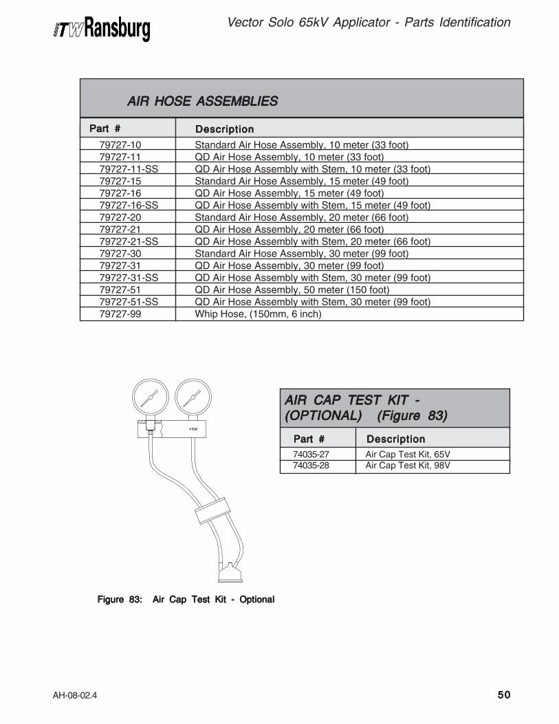
AH-08-02.4
79727-1079727-1179727-11-SS79727-1579727-1679727-16-SS79727-2079727-2179727-21-SS79727-3079727-3179727-31-SS79727-5179727-51-SS79727-99
AIR HOSE ASSEMBLIES AIR HOSE ASSEMBLIES AIR HOSE ASSEMBLIES AIR HOSE ASSEMBLIES AIR HOSE ASSEMBLIES
Part #Part #Part #Part #Part # DescriptionDescriptionDescriptionDescriptionDescription
Standard Air Hose Assembly, 10 meter (33 foot)QD Air Hose Assembly, 10 meter (33 foot)QD Air Hose Assembly with Stem, 10 meter (33 foot)Standard Air Hose Assembly, 15 meter (49 foot)QD Air Hose Assembly, 15 meter (49 foot)QD Air Hose Assembly with Stem, 15 meter (49 foot)Standard Air Hose Assembly, 20 meter (66 foot)QD Air Hose Assembly, 20 meter (66 foot)QD Air Hose Assembly with Stem, 20 meter (66 foot)Standard Air Hose Assembly, 30 meter (99 foot)QD Air Hose Assembly, 30 meter (99 foot)QD Air Hose Assembly with Stem, 30 meter (99 foot)QD Air Hose Assembly, 50 meter (150 foot)QD Air Hose Assembly with Stem, 30 meter (99 foot)Whip Hose, (150mm, 6 inch)
Figure 83: Air Cap Test Kit - OptionalFigure 83: Air Cap Test Kit - OptionalFigure 83: Air Cap Test Kit - OptionalFigure 83: Air Cap Test Kit - OptionalFigure 83: Air Cap Test Kit - Optional
74035-27 Air Cap Test Kit, 65V74035-28 Air Cap Test Kit, 98V
AIR CAP TEST KIT -AIR CAP TEST KIT -AIR CAP TEST KIT -AIR CAP TEST KIT -AIR CAP TEST KIT -(OPTIONAL) (Figure 83)(OPTIONAL) (Figure 83)(OPTIONAL) (Figure 83)(OPTIONAL) (Figure 83)(OPTIONAL) (Figure 83)
Part #Part #Part #Part #Part # DescriptionDescriptionDescriptionDescriptionDescription
Vector Solo 65kV Applicator - Parts Identification
5050505050

AH-08-02.4
Figure 84: Test and Maintenance Kit -Figure 84: Test and Maintenance Kit -Figure 84: Test and Maintenance Kit -Figure 84: Test and Maintenance Kit -Figure 84: Test and Maintenance Kit -OptionalOptionalOptionalOptionalOptional
Figure 85: Coiled Fluid TubeFigure 85: Coiled Fluid TubeFigure 85: Coiled Fluid TubeFigure 85: Coiled Fluid TubeFigure 85: Coiled Fluid Tube
79870-00 Test and Maintenance Kit
TEST AND MAINTENANCE KIT -TEST AND MAINTENANCE KIT -TEST AND MAINTENANCE KIT -TEST AND MAINTENANCE KIT -TEST AND MAINTENANCE KIT -(OPTIONAL) (Figure 84)(OPTIONAL) (Figure 84)(OPTIONAL) (Figure 84)(OPTIONAL) (Figure 84)(OPTIONAL) (Figure 84)
Part #Part #Part #Part #Part # DescriptionDescriptionDescriptionDescriptionDescription
79871-00 Coiled Fluid Tube, 3.2mm (.125"),16 Coils
79871-01 Coiled Fluid Tube, 3.2mm (.125"),12 Coils
79890-00-K5 Cover, Coiled Fluid Tube, Kit of 5
COILED FLUID TUBE -COILED FLUID TUBE -COILED FLUID TUBE -COILED FLUID TUBE -COILED FLUID TUBE -(OPTIONAL) (Figure 85)(OPTIONAL) (Figure 85)(OPTIONAL) (Figure 85)(OPTIONAL) (Figure 85)(OPTIONAL) (Figure 85)
Part #Part #Part #Part #Part # DescriptionDescriptionDescriptionDescriptionDescription
Vector Solo 65kV Applicator - Parts Identification
5151515151

AH-08-02.4
Vector Solo 65kV Applicator - Parts Identification
79837-00 Gasket, Handle to Power Module79832-00 Gasket, Barrel79836-00 Gasket, Exhaust79881-00 Gasket, Exhaust, Wraparound79876-00 Label, Voltage On/Off, Solo
79658-00 GASKET KIT -79658-00 GASKET KIT -79658-00 GASKET KIT -79658-00 GASKET KIT -79658-00 GASKET KIT -PPPPPARARARARARTS LISTTS LISTTS LISTTS LISTTS LIST
DescriptionDescriptionDescriptionDescriptionDescription Part # Part # Part # Part # Part #
The 79658-00 Gasket Kit is available for theVector Solo. This kit includes all of the gasketsrequired for an applicator rebuild.
The 79651-00 Installation and Setup Kit is availablefor the Vector Solo. This kit includes all equipmentnecesary for the installation, setup, andmaintenance of the Vector Solo applicator. Thiskit includes:
Figure 87: Installation and Setup KitFigure 87: Installation and Setup KitFigure 87: Installation and Setup KitFigure 87: Installation and Setup KitFigure 87: Installation and Setup Kit
1 Cap Pressure Test Gauges2 Test Air Caps (65V, 98V, 122V)3 100 ml Graduated Cylinder4 Analog Voltmeter5 Stop Watch6 Test and Maintenance Kit7 Wet Film Gauge
79651-00 INST79651-00 INST79651-00 INST79651-00 INST79651-00 INSTALLAALLAALLAALLAALLATION ANDTION ANDTION ANDTION ANDTION ANDSETUPSETUPSETUPSETUPSETUP KIT KIT KIT KIT KIT - P - P - P - P - PARARARARARTS LISTTS LISTTS LISTTS LISTTS LIST
DescriptionDescriptionDescriptionDescriptionDescription Item # Item # Item # Item # Item #
Figure 86: Round SprayFigure 86: Round SprayFigure 86: Round SprayFigure 86: Round SprayFigure 86: Round Spray
2 1
79959-00 Round Spray Fluid Nozzle79962-00 Round Spray Air Cap
ROUND SPRAROUND SPRAROUND SPRAROUND SPRAROUND SPRAYYYYY - - - - -(OPTIONAL) (Figure 86)(OPTIONAL) (Figure 86)(OPTIONAL) (Figure 86)(OPTIONAL) (Figure 86)(OPTIONAL) (Figure 86)
Part #Part #Part #Part #Part # DescriptionDescriptionDescriptionDescriptionDescription
5252525252

AH-08-02.4
1 79379-00 Nut, Retaining, Air Nozzle 12 79374-65 Standard Air Spray Cap, Air 1
79374-122 Trans-Tech. Air Spray Cap, Air (Included in 79555 Kit)3 79377-XX Standard Air Spray Nozzle, Fluid 1
79552-XXX Trans-Tech. Air Spray Nozzle, Fluid (Included in 79555 Kit)4 79809-00 Standard Air Spray Restrictor, Yellow, Vector 1
74963-06 Trans-Tech. Air Spray Restrictor, Green(Included in 79555 Kit)
Item #Item #Item #Item #Item #
TRANS-TECH. ATRANS-TECH. ATRANS-TECH. ATRANS-TECH. ATRANS-TECH. ATTTTTOMIZAOMIZAOMIZAOMIZAOMIZATION - PTION - PTION - PTION - PTION - PARARARARARTS LISTTS LISTTS LISTTS LISTTS LIST
Part #Part #Part #Part #Part # DescriptionDescriptionDescriptionDescriptionDescription Q t yQ t yQ t yQ t yQ t y
79374-65 Standard Air Spray Air Cap79374-65 Standard Air Spray Air Cap79374-65 Standard Air Spray Air Cap79374-65 Standard Air Spray Air Cap79374-65 Standard Air Spray Air Cap 79374-122 Trans-Tech. Air Spray Air Cap79374-122 Trans-Tech. Air Spray Air Cap79374-122 Trans-Tech. Air Spray Air Cap79374-122 Trans-Tech. Air Spray Air Cap79374-122 Trans-Tech. Air Spray Air Cap
79377-XX Standard Air Spray Fluid Nozzle79377-XX Standard Air Spray Fluid Nozzle79377-XX Standard Air Spray Fluid Nozzle79377-XX Standard Air Spray Fluid Nozzle79377-XX Standard Air Spray Fluid Nozzle 79552-XXX Trans-Tech. Air Spray79552-XXX Trans-Tech. Air Spray79552-XXX Trans-Tech. Air Spray79552-XXX Trans-Tech. Air Spray79552-XXX Trans-Tech. Air SprayFluid NozzleFluid NozzleFluid NozzleFluid NozzleFluid Nozzle
79809-00 Standard Air Spray Restrictor79809-00 Standard Air Spray Restrictor79809-00 Standard Air Spray Restrictor79809-00 Standard Air Spray Restrictor79809-00 Standard Air Spray Restrictor 74963-06 Trans-Tech. Air Spray Restrictor74963-06 Trans-Tech. Air Spray Restrictor74963-06 Trans-Tech. Air Spray Restrictor74963-06 Trans-Tech. Air Spray Restrictor74963-06 Trans-Tech. Air Spray Restrictor
PPPPPARARARARARTS COMPTS COMPTS COMPTS COMPTS COMPARISONARISONARISONARISONARISON
Standard Air Spray Nozzles havea number between 44 and 148;Trans-Tech. Air Spray Nozzleshave a number between 244and 348.
Standard Air Spray Nozzles havea longer, narrower tip; Trans-Tech.Air Spray Nozzles have a shorter,wider tip, and have a shorter over-all length.
Vector Solo 65kV Applicator - Parts Identification
5353535353

AH-08-02.4
Vector Solo 65kV Applicator - Parts Identification
5454545454
Fluid NozzleFluid NozzleFluid NozzleFluid NozzleFluid NozzlePart #Part #Part #Part #Part #Kit Part #Kit Part #Kit Part #Kit Part #Kit Part #
79555-244
79555-245
79555-247
79555-344
79555-345
79555-347
79555 TRANS-TECH. CONVERSION79555 TRANS-TECH. CONVERSION79555 TRANS-TECH. CONVERSION79555 TRANS-TECH. CONVERSION79555 TRANS-TECH. CONVERSIONKITS AKITS AKITS AKITS AKITS AVVVVVAILABLEAILABLEAILABLEAILABLEAILABLE
DescriptionDescriptionDescriptionDescriptionDescription
79552-244
79552-245
79552-247
79552-344
79552-345
79552-347
1.4mm (.055") Acetal
1.8mm (.070") Acetal
0.7mm (.028") Acetal
1.4mm (.055") Peek
1.8mm (.070") Peek
0.7mm (.028") Peek
All Kits Include: 79374-122 Air Cap, 79809-00Restrictor (yellow), and chosen Fluid Nozzle.
Kit 79555 replaces parts:
• 79809-00 Restrictor
• 79377-45 Fluid Nozzle
• 79374-65 Air Cap
NOTE: For additional information on solventViscosities and Conversion, refer to TechnicalManual IL-307 @ www.itwransburg.com.

AH-08-02.4
79377-44 Nozzle, Fluid, 1.4mm 279906-00 Assembly, Barrel, Vector Solo 179907-00 Cascade Assembly 179832-00 Gasket, Barrel 179374-65 Cap, Air, 65R 279724-00 Nut, Retaining, Air Nozzle 1LSOR0005 O-Ring, Teflon Encapsulated 1EMF-202-05 Ferrule, Back, 3/8" Tube 2EMF-203-05 Ferrule, Front, 3/8" Tube 279878-12 Tube, Fluid Inlet, 3.2mm ID (.125") 179878-13 Tube, Fluid Inlet, 3.4mm ID (.250") 179878-11 Tube, Fluid Inlet, 2.4mm ID (.093"), 216mm, 8 1/2" Lg. 1
(Standard W/Applicator)79787-00 Assembly, Trigger 179454-00 Screw, Trigger Retention 279768-00 Nut, Fluid Jam, Front 179744-00 Spring, Air Valve Return 179835-00 Assembly, Power Module (Includes Items 39, 40, 41, 42, and 43) 179768-00 Nut, Fluid Jam,Spring Guide 178636-00 Spring 179781-00 Seal, Adjustment Bushing 179837-00 Gasket, Handle to Power Module 179809-00 Pressure Reducer, Atomizing Air, Vector Solo (Yellow) 179911-00 Kit, Shaft Assembly, 2-Piece Needle, Vector Solo 179760-00 Seal, Air Valve 179847-00 Valve, Compensation Atomizing 179755-00 Fluid Inlet 179836-00 Gasket, Exhaust 179843-00 Assembly, Exhaust Housing 179529-00-K5 Applicator Cover 2LSCH0009-00 Dielectric Grease 2
VECTVECTVECTVECTVECTOR SOLO RECOMMENDED SPOR SOLO RECOMMENDED SPOR SOLO RECOMMENDED SPOR SOLO RECOMMENDED SPOR SOLO RECOMMENDED SPARE PARE PARE PARE PARE PARARARARARTSTSTSTSTS(Quantities Per Applicator)(Quantities Per Applicator)(Quantities Per Applicator)(Quantities Per Applicator)(Quantities Per Applicator)
Part #Part #Part #Part #Part # DescriptionDescriptionDescriptionDescriptionDescription Q t yQ t yQ t yQ t yQ t y
Vector Solo 65kV Applicator - Parts Identification
5555555555
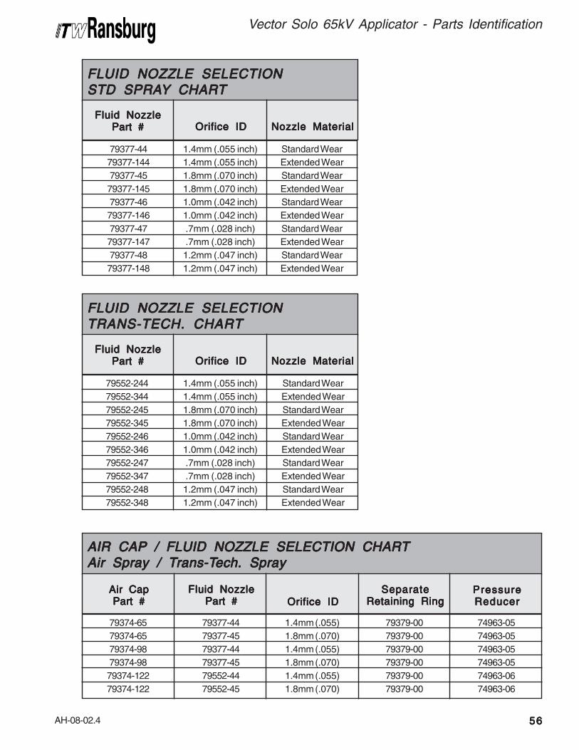
AH-08-02.4
Orifice IDOrifice IDOrifice IDOrifice IDOrifice IDFluid NozzleFluid NozzleFluid NozzleFluid NozzleFluid Nozzle
Part #Part #Part #Part #Part #
79377-44
79377-144
79377-45
79377-145
79377-46
79377-146
79377-47
79377-147
79377-48
79377-148
FLUID NOZZLE SELECTIONFLUID NOZZLE SELECTIONFLUID NOZZLE SELECTIONFLUID NOZZLE SELECTIONFLUID NOZZLE SELECTIONSTD SPRASTD SPRASTD SPRASTD SPRASTD SPRAYYYYY CHAR CHAR CHAR CHAR CHARTTTTT
Nozzle MaterialNozzle MaterialNozzle MaterialNozzle MaterialNozzle Material
1.4mm (.055 inch)
1.4mm (.055 inch)
1.8mm (.070 inch)
1.8mm (.070 inch)
1.0mm (.042 inch)
1.0mm (.042 inch)
.7mm (.028 inch)
.7mm (.028 inch)
1.2mm (.047 inch)
1.2mm (.047 inch)
Standard Wear
Extended Wear
Standard Wear
Extended Wear
Standard Wear
Extended Wear
Standard Wear
Extended Wear
Standard Wear
Extended Wear
Orifice IDOrifice IDOrifice IDOrifice IDOrifice IDFluid NozzleFluid NozzleFluid NozzleFluid NozzleFluid Nozzle
Part #Part #Part #Part #Part #
79552-244
79552-344
79552-245
79552-345
79552-246
79552-346
79552-247
79552-347
79552-248
79552-348
FLUID NOZZLE SELECTIONFLUID NOZZLE SELECTIONFLUID NOZZLE SELECTIONFLUID NOZZLE SELECTIONFLUID NOZZLE SELECTIONTRANS-TECH. CHARTTRANS-TECH. CHARTTRANS-TECH. CHARTTRANS-TECH. CHARTTRANS-TECH. CHART
Nozzle MaterialNozzle MaterialNozzle MaterialNozzle MaterialNozzle Material
1.4mm (.055 inch)
1.4mm (.055 inch)
1.8mm (.070 inch)
1.8mm (.070 inch)
1.0mm (.042 inch)
1.0mm (.042 inch)
.7mm (.028 inch)
.7mm (.028 inch)
1.2mm (.047 inch)
1.2mm (.047 inch)
Standard Wear
Extended Wear
Standard Wear
Extended Wear
Standard Wear
Extended Wear
Standard Wear
Extended Wear
Standard Wear
Extended Wear
79374-65
79374-65
79374-98
79374-98
79374-122
79374-122
Air CapAir CapAir CapAir CapAir CapPart #Part #Part #Part #Part # Orifice IDOrifice IDOrifice IDOrifice IDOrifice ID
Fluid NozzleFluid NozzleFluid NozzleFluid NozzleFluid NozzlePart #Part #Part #Part #Part #
79377-44
79377-45
79377-44
79377-45
79552-44
79552-45
AIR CAP / FLUID NOZZLE SELECTION CHARTAIR CAP / FLUID NOZZLE SELECTION CHARTAIR CAP / FLUID NOZZLE SELECTION CHARTAIR CAP / FLUID NOZZLE SELECTION CHARTAIR CAP / FLUID NOZZLE SELECTION CHARTAir Spray / TAir Spray / TAir Spray / TAir Spray / TAir Spray / Trans-Trans-Trans-Trans-Trans-Tech. Sprayech. Sprayech. Sprayech. Sprayech. Spray
SeparateSeparateSeparateSeparateSeparateRetaining RingRetaining RingRetaining RingRetaining RingRetaining Ring
PressurePressurePressurePressurePressureReducerReducerReducerReducerReducer
1.4mm (.055)
1.8mm (.070)
1.4mm (.055)
1.8mm (.070)
1.4mm (.055)
1.8mm (.070)
79379-00
79379-00
79379-00
79379-00
79379-00
79379-00
74963-05
74963-05
74963-05
74963-05
74963-06
74963-06
5656565656
Vector Solo 65kV Applicator - Parts Identification

AH-08-02.4
Vector Solo 65kV Applicators- Parts Identification
5757575757
NOTESNOTESNOTESNOTESNOTES

AH-08-02.4
WWWWWARRANTYARRANTYARRANTYARRANTYARRANTY POLICIES POLICIES POLICIES POLICIES POLICIES
LIMITED WLIMITED WLIMITED WLIMITED WLIMITED WARRANTYARRANTYARRANTYARRANTYARRANTY
ITW RansburgITW RansburgITW RansburgITW RansburgITW Ransburg will replace or repair withoutcharge any part and/or equipment that fails withinthe specified time (see below) because of faultyworkmanship or material, provided that theequipment has been used and maintained inaccordance with ITW Ransburg’s written safetyand operating instructions, and has been usedunder normal operating conditions. Normal wearitems are excluded.
THE USE OF OTHER THAN ITW RANS-THE USE OF OTHER THAN ITW RANS-THE USE OF OTHER THAN ITW RANS-THE USE OF OTHER THAN ITW RANS-THE USE OF OTHER THAN ITW RANS-
BURG APPROVED PARTS VOID ALLBURG APPROVED PARTS VOID ALLBURG APPROVED PARTS VOID ALLBURG APPROVED PARTS VOID ALLBURG APPROVED PARTS VOID ALL
WARRANTIES.WARRANTIES.WARRANTIES.WARRANTIES.WARRANTIES.
SPARE PARTS: One hundred and eighty (180)days from date of purchase, except for rebuiltparts (any part number ending in “R”) for which thewarranty period is ninety (90) days.
EQUIPMENT: When purchased as a completeunit, (i.e., guns, power supplies, control units,etc.), is one (1) year from date of purchase.
WRAPPING THE APPLICATOR, ASSO-WRAPPING THE APPLICATOR, ASSO-WRAPPING THE APPLICATOR, ASSO-WRAPPING THE APPLICATOR, ASSO-WRAPPING THE APPLICATOR, ASSO-
CIATED VALVES AND TUBING, ANDCIATED VALVES AND TUBING, ANDCIATED VALVES AND TUBING, ANDCIATED VALVES AND TUBING, ANDCIATED VALVES AND TUBING, AND
SUPPORTING HARDWARE IN PLASTIC,SUPPORTING HARDWARE IN PLASTIC,SUPPORTING HARDWARE IN PLASTIC,SUPPORTING HARDWARE IN PLASTIC,SUPPORTING HARDWARE IN PLASTIC,
SHRINK-WRAP, OR ANY OTHER NON-SHRINK-WRAP, OR ANY OTHER NON-SHRINK-WRAP, OR ANY OTHER NON-SHRINK-WRAP, OR ANY OTHER NON-SHRINK-WRAP, OR ANY OTHER NON-
APPROVED COVERING, WILL VOID THISAPPROVED COVERING, WILL VOID THISAPPROVED COVERING, WILL VOID THISAPPROVED COVERING, WILL VOID THISAPPROVED COVERING, WILL VOID THIS
WARRANTY.WARRANTY.WARRANTY.WARRANTY.WARRANTY.
ITW RANSBURG’S ONLY OBLIGATIONITW RANSBURG’S ONLY OBLIGATIONITW RANSBURG’S ONLY OBLIGATIONITW RANSBURG’S ONLY OBLIGATIONITW RANSBURG’S ONLY OBLIGATION
UNDER THIS WARRANTY IS TO REPLACEUNDER THIS WARRANTY IS TO REPLACEUNDER THIS WARRANTY IS TO REPLACEUNDER THIS WARRANTY IS TO REPLACEUNDER THIS WARRANTY IS TO REPLACE
PARTS THAT HAVE FAILED BECAUSEPARTS THAT HAVE FAILED BECAUSEPARTS THAT HAVE FAILED BECAUSEPARTS THAT HAVE FAILED BECAUSEPARTS THAT HAVE FAILED BECAUSE
OF FAULTY WORKMANSHIP OR MATER-OF FAULTY WORKMANSHIP OR MATER-OF FAULTY WORKMANSHIP OR MATER-OF FAULTY WORKMANSHIP OR MATER-OF FAULTY WORKMANSHIP OR MATER-
IALS. THERE ARE NO IMPLIED WARRAN-IALS. THERE ARE NO IMPLIED WARRAN-IALS. THERE ARE NO IMPLIED WARRAN-IALS. THERE ARE NO IMPLIED WARRAN-IALS. THERE ARE NO IMPLIED WARRAN-
TIES NOR WARRANTIES OF EITHERTIES NOR WARRANTIES OF EITHERTIES NOR WARRANTIES OF EITHERTIES NOR WARRANTIES OF EITHERTIES NOR WARRANTIES OF EITHER
MERCHANTABILITY OR FITNESS FOR AMERCHANTABILITY OR FITNESS FOR AMERCHANTABILITY OR FITNESS FOR AMERCHANTABILITY OR FITNESS FOR AMERCHANTABILITY OR FITNESS FOR A
PARTICULAR PURPOSE. ITW RANS-PARTICULAR PURPOSE. ITW RANS-PARTICULAR PURPOSE. ITW RANS-PARTICULAR PURPOSE. ITW RANS-PARTICULAR PURPOSE. ITW RANS-
BURG ASSUMES NO LIABILITY FORBURG ASSUMES NO LIABILITY FORBURG ASSUMES NO LIABILITY FORBURG ASSUMES NO LIABILITY FORBURG ASSUMES NO LIABILITY FOR
INJURY, DAMAGE TO PROPERTY ORINJURY, DAMAGE TO PROPERTY ORINJURY, DAMAGE TO PROPERTY ORINJURY, DAMAGE TO PROPERTY ORINJURY, DAMAGE TO PROPERTY OR
FOR CONSEQUENTIAL DAMAGES FORFOR CONSEQUENTIAL DAMAGES FORFOR CONSEQUENTIAL DAMAGES FORFOR CONSEQUENTIAL DAMAGES FORFOR CONSEQUENTIAL DAMAGES FOR
LOSS OF GOODWILL OR PRODUCTIONLOSS OF GOODWILL OR PRODUCTIONLOSS OF GOODWILL OR PRODUCTIONLOSS OF GOODWILL OR PRODUCTIONLOSS OF GOODWILL OR PRODUCTION
OR INCOME, WHICH RESULT FROM USEOR INCOME, WHICH RESULT FROM USEOR INCOME, WHICH RESULT FROM USEOR INCOME, WHICH RESULT FROM USEOR INCOME, WHICH RESULT FROM USE
OR MISUSE OF THE EQUIPMENT BYOR MISUSE OF THE EQUIPMENT BYOR MISUSE OF THE EQUIPMENT BYOR MISUSE OF THE EQUIPMENT BYOR MISUSE OF THE EQUIPMENT BY
PURCHASER OR OTHERS.PURCHASER OR OTHERS.PURCHASER OR OTHERS.PURCHASER OR OTHERS.PURCHASER OR OTHERS.
EXCLUSIONS:EXCLUSIONS:EXCLUSIONS:EXCLUSIONS:EXCLUSIONS:
If, in ITW Ransburg’s opinion the warranty item inquestion, or other items damaged by this part wasimproperly installed, operated or maintained, ITWRansburg will assume no responsibility for repairor replacement of the item or items. Thepurchaser, therefore, will assume all responsibilityfor any cost of repair or replacement and servicerelated costs if applicable.
Vector Solo 65kV Applicator - Warranty Policies
5858585858

AH-08-02.4
MANUALMANUALMANUALMANUALMANUAL CHANGE SUMMAR CHANGE SUMMAR CHANGE SUMMAR CHANGE SUMMAR CHANGE SUMMARYYYYYAH-08-02.4 includes the followingchanges:
In "Atex/FM" section, the 79944configuration drawing was updatedto reflect the current productoffering.
In "Parts Identification" section, themodel identification was updatedto reflect the current productoffering.
In "Parts Identification" section,Table D was updated to reflectcurrent product offering and newround spray part numbers.

Form No. AH-08-02.4Litho in U.S.A.12/11
© 2011 Illinois Tool Works Inc. All rights reserved.Models and specifications subject to change without notice.
Service Manual Price:Service Manual Price:Service Manual Price:Service Manual Price:Service Manual Price: €40.00 (Euro)$50.00 (U.S.)$50.00 (U.S.)$50.00 (U.S.)$50.00 (U.S.)$50.00 (U.S.)
ManufacturingManufacturingManufacturingManufacturingManufacturing1910 North Wayne StreetAngola, Indiana 46703-9100Telephone: 260/665-8800Fax: 260/665-8516www.itwransburg.com
TTTTTechnical/Service Assistanceechnical/Service Assistanceechnical/Service Assistanceechnical/Service Assistanceechnical/Service Assistance Telephone: 800/ 626-3565 Fax: 419/470-2040Telephone: 800/ 233-3366 Fax: 419/ 470-2071
TTTTTechnical Support Representative will direct you to the appropriate telephoneechnical Support Representative will direct you to the appropriate telephoneechnical Support Representative will direct you to the appropriate telephoneechnical Support Representative will direct you to the appropriate telephoneechnical Support Representative will direct you to the appropriate telephone
number for ordering Spare Parts.number for ordering Spare Parts.number for ordering Spare Parts.number for ordering Spare Parts.number for ordering Spare Parts.