aida syamsiah binti mohd yusof report submitted in … · dissimilar welding or tailor welded ......
TRANSCRIPT

2
INVESTIGATION OF HEAT TREATMENT ON WELD JOINT OF STEEL AND
ALUMINUM
AIDA SYAMSIAH BINTI MOHD YUSOF
Report submitted in partial fulfillment of the requirements for the award
of Bachelor of Mechanical Engineering with Manufacturing Engineering
Faculty Of Mechanical Engineering
UNIVERSITI MALAYSIA PAHANG
JUNE 2012

6
ABSTRACT
Dissimilar welding or Tailor Welded Blank (TWB) joint is defined as two or more
sheets with equal or different materials, thickness, strength, or surface coatings are welded
together. The objective of this project is to investigate the effect of heat treatment on the
weld joints quality and determined the mechanical properties of the steel-aluminum weld
joint. This project was performed to join aluminum alloy AA1100with stainless steel SUS
304in the thickness range of 3 mm in lap joint configuration. Among theprocess parameters
varied were current flow, pre heating process. By metallurgy cross sections, hardness test
and tensiletests, the effect of these process parameters on joint properties such as welding
joint hardness, macrostructure defect and tensile strength could be elucidated. Based on
theseresults, the penetration of the stainless steel with aluminum alloy will occur when the
preheating process is applied. The optimum current without preheating is 85A and 95A for
preheating process at 85ºC.

7
ABSTRAK
Kimpalanberbezaatau Tailor Welded Blank (TWB) sambungan didefinisikan
sebagai dua atau lebih kepingan dengan sama atau berbeza bahan, ketebalan, kekuatan, atau
lapisan permukaan yang dikimpalkan bersama. Objektif projek ini ialah untuk menyiasat
kualiti kesan dari pemanasan dan sifat-sifat mekanika lsambungan aluminium keluli. Projek
ini dijalankan diantara aloi aluminium AA1100 dengan keluli tahan karat SUS 304 dalam
julat ketebalan 3 mm dengan tatarajah sambungan tindih. Antara parameter yang
dipelbagaikan merupakan aliran arus elektrik, proses pemanasan sebelum. Dengan keratin
rentas metalurgi, ujian ketahan, kesan dari parameter yang pelbagai, kecacatan
makrostrutur dapat dilihat dan dijelaskan. Berdasarkan keputusan kajian, penembusan
keluli tahan karat terhadap aloi aluminium terjadi semasa proses pemanasan diaplikasikan.
Arus yang optima apabila tanpa pemanasan awal dijalankan adalah 85A dan dengan
pemanasan awal pada suhu 85ºC adalah 95A.
8
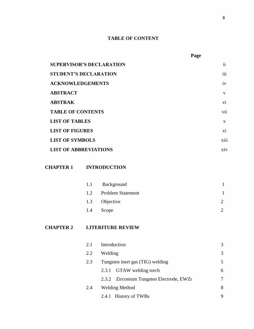
TABLE OF CONTENT
Page
SUPERVISOR’S DECLARATION ii
STUDENT’S DECLARATION iii
ACKNOWLEDGEMENTS iv
ABSTRACT v
ABSTRAK vi
TABLE OF CONTENTS vii
LIST OF TABLES x
LIST OF FIGURES xi
LIST OF SYMBOLS xiii
LIST OF ABBREVIATIONS xiv
CHAPTER 1 INTRODUCTION
1.1 Background 1
1.2 Problem Statement 1
1.3 Objective 2
1.4 Scope 2
CHAPTER 2 LITERITURE REVIEW
2.1 Introduction 3
2.2 Welding 3
2.3 Tungsten inert gas (TIG) welding 5
2.3.1 GTAW welding torch 6
2.3.2 Zirconium Tungsten Electrode, EWZr 7
2.4 Welding Method 8
2.4.1 History of TWBs 9

9
2.4.2Benefits of Tailor Welded Blanks (TWBs) 10
2.4.2.1 Reduction of Final Car Weight 10
2.4.2.2 Reduction of Automobile
Parts Number 11
2.4.2.3 Improved Raw Material Utilization and
Reductionof Scrap. 12
2.5 Materials 12
2.5.1 Aluminum 12
2.5.2 Stainless Steel 13
2.5.3 Weldability of Steel- Aluminum 13
2.5.4 Preheating of Steel to Improve Weldability 15
CHAPTER 3 METHODOLOGY
3.1 Introduction 16
3.2 Material Selection 16
3.2.1 Aluminum 16
3.2.2 Stainless Steel 18
3.3 Fabrication Process 18
3.3.1 Process Involve 19
3.3.1.1 Measuring and Cutting 19
3.3.1.2 Joining Process 20
3.4 Specimen’s Mechanical Properties 21
3.4.1 Tensile Test 21
3.4.1.1 The Tensile Test
Specimens Dimension 23
3.4.2 Hardness Test 23
3.5 Microstructure and Phase
Composition analysis 24
3.5.1 Cold Mounting 24
3.5.2 Grinding 25

10
3.5.3 Polishing 26
3.5.4 Etching 27
3.5.5 Analysis of Microstructure 27
3.6 Flow Chart 28
CHAPTER 4 RESULT AND DISCUSSION
4.1 Introduction 29
4.2 Result
4.2.1 Appearance and macrostructure 29
Group 1: Without preheating process
Group 2: With preheating process
4.2.2 Microstructure of the welding joints 33
Group 1: Without preheating process
Group 2: With preheating process
4.2.3 Hardness distributation test 36
Group 1: Without preheating process
Group 2: With preheating process
4.2.4 Mechanical properties 38
Group 1: Without preheating process
Group 2: With preheating process
CHAPTER 5 CONCLUSION AND RECOMMENDATION
5.1 Introduction 43
5.2 Conclusion 43
5.3 Recommendation 44
5.3.1 Cracks 44
5.3.2 Cold cracking 44
5.3.3 Pre-heating 45
REFERENCES 46
APPENDIX
11
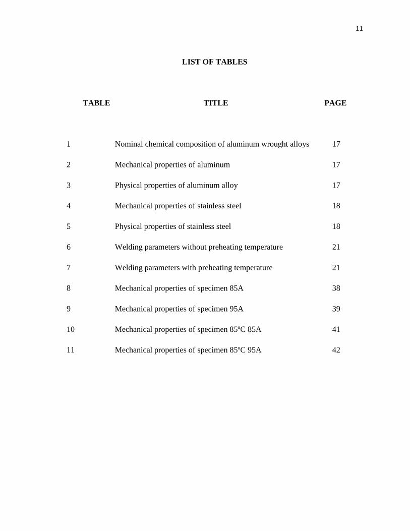
LIST OF TABLES
TABLE TITLE PAGE
1 Nominal chemical composition of aluminum wrought alloys 17
2 Mechanical properties of aluminum 17
3 Physical properties of aluminum alloy 17
4 Mechanical properties of stainless steel 18
5 Physical properties of stainless steel 18
6 Welding parameters without preheating temperature 21
7 Welding parameters with preheating temperature 21
8 Mechanical properties of specimen 85A 38
9 Mechanical properties of specimen 95A 39
10 Mechanical properties of specimen 85ºC 85A 41
11 Mechanical properties of specimen 85ºC 95A 42

12
LIST OF FIGURES
FIGURE TITLE PAGES
1 Cross section of a typical fusion welded joint 4
2 Tungsten Inert Gas (TIG) Welding 5
3 Zirconium Tungsten, EWZr 7
4 Micro-geometrical parameters for seam assessment 8
5 The change of stamping procedure 9
6 The first application example of tailor welded blanks,(TWBs) 10
7 present application of tailor welded blanks, (TWBs) 10
8 Exploded view of current or potential tailor welded blanks body
component 11
9 Appearances of the joint with different base metal 14
10 The cross-section of lap joint 14
11 Shearing machine 18
12 TIG welding machine and process 20
13 Tensile test machine 22
14 Geometry of rectangular tensile test specimens (ASTM D1002) 23
15 Vickers hardness test machine 24
16 Cold mounting 25
17 Grinding machine 25
18 Polishing machine 26
19 (a) The solution for etching (b) fume hood 27
20 Optical microscope 27

13
21 Flowchart of overall methodology. 28
22 (Sample A) Cross section of welding for 65A 30
23 (Sample B) Cross section of welding for 85A 30
24 (Sample C) Cross section of welding for 95A 30
25 (Sample D) Cross section of welding for 85ºC 65A 31
26 (Sample E) Cross section of welding for 85ºC 85A 31
27 (Sample F) Cross section of welding for 85ºC 95A 32
28 Dendrite structure of the weldament area for Group 1 33
29 Intermetallic compound structure of the HAZ area for Group 2 33
30 Dendrite structure of the weldament area for Group 1 34
31 Intermetallic compound structure of the HAZ area for Group 2 34
32 Hardness distributation for Group 1 36
33 Hardness distributation for Group 2 37
34 Graph of specimen 85A 38
35 Graph of specimen 95A 39
36 Graph of specimen 85ºC 85A 40
37 Graph of specimen 85ºC 95A 41

14
LIST OF SYMBOLS
Strain
Stress
A Area
F Force
Kg Kilogramme
mm millimeter
MPa Mega Pascal
N Newton
Lo initial length
L final length
HV Vickers hardness
A ampere
ºC Celsius
15
CHAPTER 1
INTRODUCTION
1.1 Background
Dissimilar metal joining offers the potential to utilize the advantages of different
materials often providing a whole structure with unique mechanical property. Recently
dissimilar welding of metallic alloy sheet has gotten attention due to its manufacturing cost
and working operation reduction ability. Aluminum can reduce the weight of structural
parts for its lightweight and stainless steel has a high strength and excellent corrosion
resistance. Even so, the process yields the brittle intermetallic reaction phase formation on
the weld joint and the cracks propagate across the matrix of the grains. So, this project
looks into the effect of heat treatment on the quality of the weld joint and defect that may
occur during the heat treatment process of steel-aluminum sheets. The mechanical
properties of the specimens are also investigated.
1.2 Problem Statement
This project focuses on joining two different materials by using TIG welding. The
method that is selected is tailor welded blanks but a few problems are predicted when
joining the material. Since the materials used are stainless steel and aluminum, when steel
and aluminum are welded together, steel sheets tend not to melt and join well with the
aluminum sheets. This is due to the heat created by the welding process does not exceed the
melting point of steel. This in turn will decrease the mechanical properties of the joint area.
In order to improve the joining of these materials in the joint area, one method where the
steel sheets are pre-heated to a higher temperature from ambient temperature before the
welding process is proposed with various current.

16
1.3 Objective
The project objectives are:
To investigate the effect of heat treatment on the weld joints quality, and
To determine the mechanical properties of the steel-aluminum weld joint.
1.4 Scope
The scopes for this project are:
i. Fabrication of steel- aluminum welded sheets
ii. Investigation of the heat treatment (preheat) effect on weld joint quality by
using tensile test and Vickers hardness test, and
iii. Investigation of the specimen’s microstructure using optical microstructure.
17
CHAPTER 2
LITERATURE REVIEW
2.1 INTRODUCTION
The purpose of this chapter is to provide a review of welding field and past research
efforts related to the Tailor Welded Blanks (TWBs). A review of other relevant research
studies is also provided. Substantial literature has been studied on history, definition,
benefits and also production methods.
2.2 WELDING
Welding is the only way of joining of two or more pieces of metal to make them act
as a single piece. It is used to join all commercial metals and alloys and also to join together
metals of different types and strengths. The history of joining metals goes back several
millennia, with the earliest examples of welding from the Bronze Age and the Iron Age in
Europe and the Middle East. Welding was used in the construction of the iron pillar in
Delhi, India, erected about 310 AD. Then, the production of an arc between two carbon
electrodes using battery is credited to Sir Humphry Davy in 1800 and developed until 1900.
After that, it was largely replaced with arc welding, as metal coverings (known as flux) for
the electrode that stabilize the arc and shield the base material from impurities continued to
be developed until now.( Howard B.Cary, 2002).

18
They are between the interface of the deposited weld metal and extending into the
base metal far enough that any phase change occurs is known as the heat affected zone
(HAZ). HAZ and the admixture zone are the most critical area in any welds. On the other
hand, when welding a hardened steel the HAZ can become a softened zone since the heat of
the weld has annealed the hardened metal. Figure 1 shows the cross section of a typical
fusion welded joint. ( Howard B.Cary, 2002).
Figure 1: Cross section of a typical fusion welded joint:
(a) Principal zones in the joint. (b) Typical grain structure
Source: Serope Kalpakjian, Steven R.Schmid (2001)
There are many types of welding, which are gas welding, arc welding, resistance
welding, solid state welding, radiant energy welding and thermo-chemical welding.
Tungsten innert gas welding (TIG) is one of the type of arc welding.( Howard B.Cary,
2002)

19
2.3 TUNGSTEN INERT GAS (TIG) WELDING
One of the most common method practiced locally to join metal part is Tungsten
Inert Gas (TIG) welding. Figure 2 shows the TIG machine.
Figure 2: Tungsten Inert Gas (TIG) Welding
Source: Welding And Metal Fabrications, Larry Jeffus (2010)
The gas Tungsten Arc Welding, (GTAW) process is sometimes referred to as TIG,
or heliarc. The term TIG is short for tungsten innert gas welding. Under the correct welding
conditions, the tungsten electrode does not melt and considered to be non consumable. The
surface of the metal being welded does melt at the spot where the arc impacts its surface.
This produces a molten weld pool. Figure 2 shows the TIG machine by Millers.
To make a weld, either the edges of the metal must melt and flow together by
themselves or a filler metal must be added directly into the molten pool. Filler metal is
added by dipping the end of the filler rod into the leading edge of the molten weld pool.
Most metals oxidize rapidly in their molten state. To prevent oxidation from occuring, an
innert gas flows out of the welding torch, surrounding the hot tungsten and molten weld
metal shielding it from atmospheric oxygen.
20
GTAW welding is efficient for welding metals raging from sheet metal up to ¼
inch. The eye-hand coordination required to make GTAW welds is very similar to the
coordination required for oxyfuel gas welding.
Two of the advantages of GTAW welding for welding fabrication are that it can be
used to produce very high quality welds and it can be used to weld on almost any metal
There are also limitation of GTAW welding, which are the slow welding rate and
tedious nature, both of which limit its use to small projects or high integrity critical welds.
(Welding and Metal Fabrications, Larry Jeffus, 2010)
2.3.1 GTAW welding torch
GTAW welding torches are available water cooled or air cooled. The heat transfer
efficiency for GTAW welding may be as low as 20%. This means that 80% of the heat
generated does not enter the weld but stay in the torch. To avoid damage to the torch, the
heat must be removing. (Welding And Metal Fabrications, Larry Jeffus, 2010)
a) Following are some of the advantages of air cooled GTAW torch:
Lighter weight for the same amperage range
More portable
Easier to maintain
No water supply required
No water leakage danger
b) But there are also disadvantages of air cooled GTAW torch:
Cannot sustain continuous operation without over heating
High torch temperature means more tungsten erosion
More torch handle temperature in the welder’s hands
21
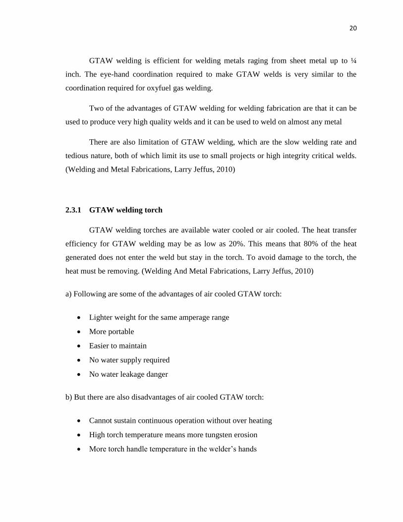
2.3.2 Zirconium Tungsten Electrode, EWZr
The high melting temperature and good electrical conductivity make tungsten the
best choice for a non-consumable electrode. So the zirconium tungsten electrode is chosen
as shown in Figure 3. Zirconium oxide (ZrO²) helps tungsten emit electrons freely. Because
zirconium tungsten is more easily melted than thorium tungsten, ZrO² electrodes can be
used with both AC and DC current. Also because of the ease in forming the desired balled
end on thorium versus zirconium tungsten, they are normally the electrode chosen for AC
welding of aluminum and magnesium alloys. Zirconiated tungsten is more resistant to weld
pool contamination than pure tungsten, thus providing excellent weld qualities with
minimal contamination. (Welding and Metal Fabrications, Larry Jeffus, 2010)
Figure 3: Zirconium Tungsten, EWZr
Source: Gebeng ILP Labaratory
22
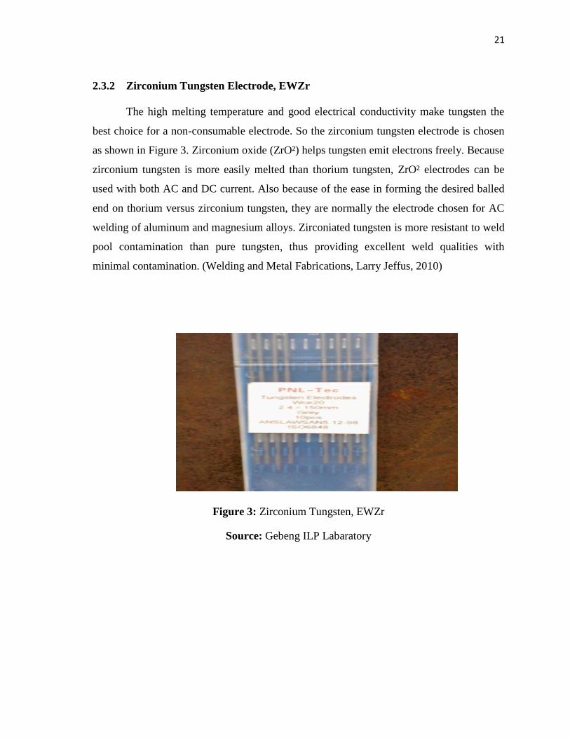
2.4 WELDING METHOD
The welding method that is used for this project is Tailor Welded Blanks (TWBs).
The TWBs is defined as two or more separate pieces of flat material, dissimilar thickness,
and mechanical properties which are jointed together before forming to provide good
qualities on the finished stamping,( Yan, Qi, China Welding 2, 2002) . Figure 4 shows
wetting length and seam reinforcement on top and bottom of specimen. The traditional
procedure in automobile industry was to stamp the parts with different thickness and
material one by one before the welding process, but with this process the combination of
different thickness and material is formed first with welding process then future process
will take part. Figure 5 shows the change of stamping procedure in automobile industry by
using TWBs.
Figure 4: Micro-geometrical parameters for seam assessment
Source: C Thomy and F vollertsen, 2009

23
a) Traditional stamping procedure, b) Stamping procedure using tailor welded balnks
Figure 5: The change of stamping procedure
Source: Yan, Qi, China Welding, (2002)
2.4.1 History of TWBs
The first application of TWBs occurred in 1985 which is used by production of
front floor for Audi,( Waddel.W, 1995). Figure 6 shows the front floor pans using this
technology to provide wide width sheets for car industry. Currently, this technology is
widely used in various occasions which incorporate steel with various type and thicknesses.
Figure 7 shows a rail part using TWBs but with different thickness and material. TWBs
offer an opportunity to reduce manufacturing cost, decrease vehicle and improve the
quality of sheet metal stampings. Besides that, it can also improve crashworthiness,
improve dimensional accuracy of the final parts and increase corrosion resistence,(Auto/
Steel Partnership, 1995).

24
Figure 6: The first application example of tailor welded blanks, (TWBs)
Source: Yan, Qi, China Welding, (2002)
Figure 7: The present application of tailor welded blanks, (TWBs)
Source: Yan, Qi, China Welding, (2002)
2.4.2 Benefits of Tailor Welded Blanks (TWBs)
There are some of benefits of TWBs method, which are:
2.4.2.1 Reduction of Final Car Weight
TWBs eliminate the need for reinforcement, resulting in an overall reduction in
vehicle body weight. The use of different thickness in a single part can simplify the whole
structure of vehicle,(Yan, Qi, China Welding , 2002)

25
2.4.2.2 Reduction of Automobile Parts Number
The precision of car body structure can be improved and a lot of press equipment
and working can be utilized. For example the door inner, by using tailor welded blanks with
a large, thin, soft piece of material jointed to a smaller, thicker, stronger piece of material,
can be formed and used as a one piece door inner. Figure 8 shows a schematic of current
and potential (TWBs) applications in the automobile industry, (Auto/Steel Partnership,
1995).
Figure 8: Exploded view of current or potential Tailor Welded Blanks body component
Source: Journal of Forming of Aluminum tailor welded blanks, 2001

26
2.4.2.3 Improved Raw Material Utilization and Reduction of Scrap.
By selecting the use of higher strength, and heavier gauge material to the specific
areas where they are required, the reduction in material could be realized. By nesting
various blanks during the blanking process, engineered scrap can also be reduced.
2.5 MATERIALS
Since the objective of this project is to joint two different materials, aluminum and
stainless steel are choosen for this research.
2.5.1 Aluminium
The unique combination of light weight relatively high strength makes aluminium
the second most popular metal that is welded. Aluminium is not difficult to joint, but
aluminium welding is different from welding steels. A system of four digit number has
been developed by Aluminium Association, Inc., and adopted by the American Society for
Testing Materials (ASTM) it designate the wrought aluminium alloy types. The series that
used for this project is 1XXX series which is the aluminium is 99% or higher
purity.(Howard B.Cary, 2002).
Aluminium possesses a number of properties that make welding different than
welding steel, these are:
Aluminium oxide surface coating
High thermal conductivity
High thermal expansion coefficient
Low melting temperature
The absence of color change as temperature approaches the melting point
(dull red)

27
2.5.2 Stainless Steel
Stainless steel or, more precisely, corrosion-resisting steel are a family of iron-base
alloys having excellent resistance to corrosion. The steel do not rust and strongly resist
attack by a great many liquids, gases, and chemicals. Many of the stainless steel have good
low temperature toughness and ductility. Most stainless steels exhibit good strength
properties and resistance to scaling at high temperature. All stainless steel contain iron as
the main element and chromium in amounts ranging from about 11% to 30%. Chromium
provides the basic corrosion resistance to stainless steel. ( Howard B.Cary, 2002)
Stainless steel are slightly more difficult to weld compared to mild steels. The
physical properties of stainless steel are different from mild steel and this makes it weld
differently. These differences are:
Lower melting temperature
Lower coefficient of thermal conductivity
Higher coefficient of thermal expansion
Higher electrical resistance
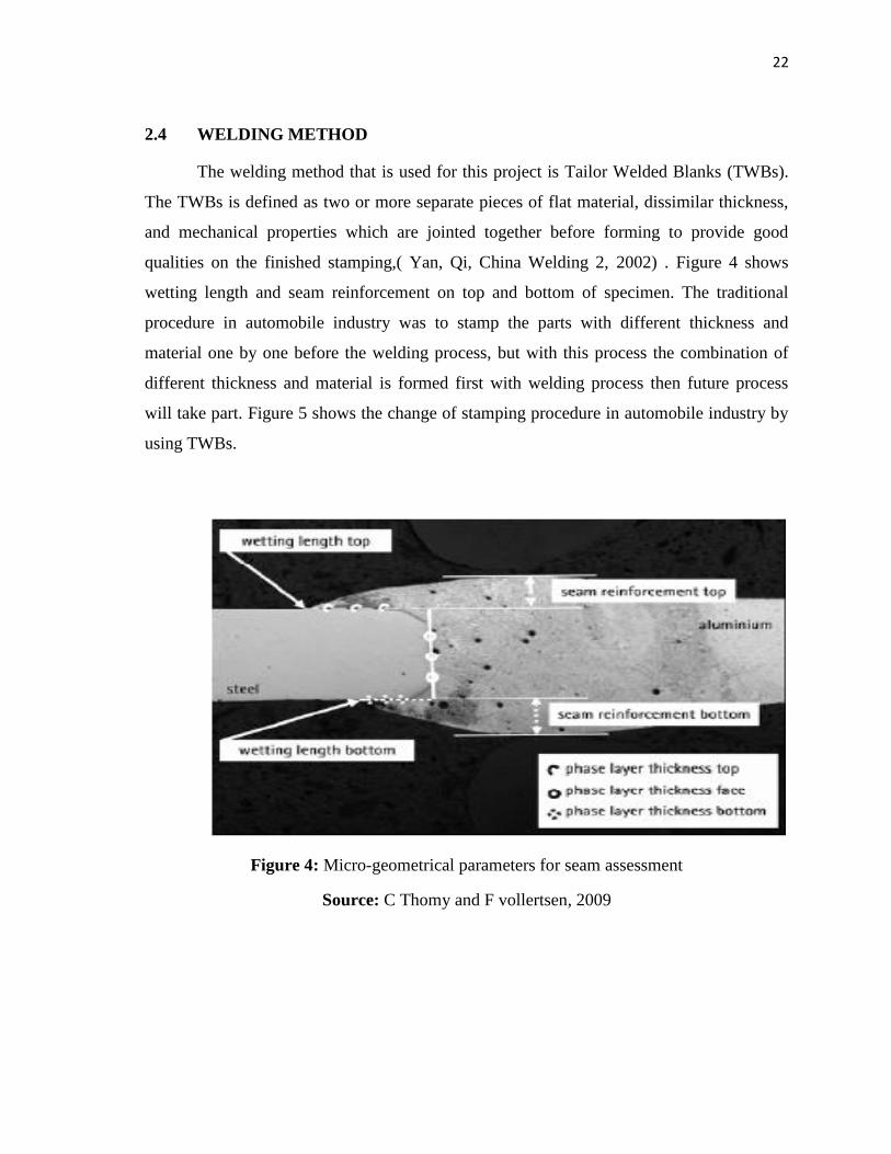
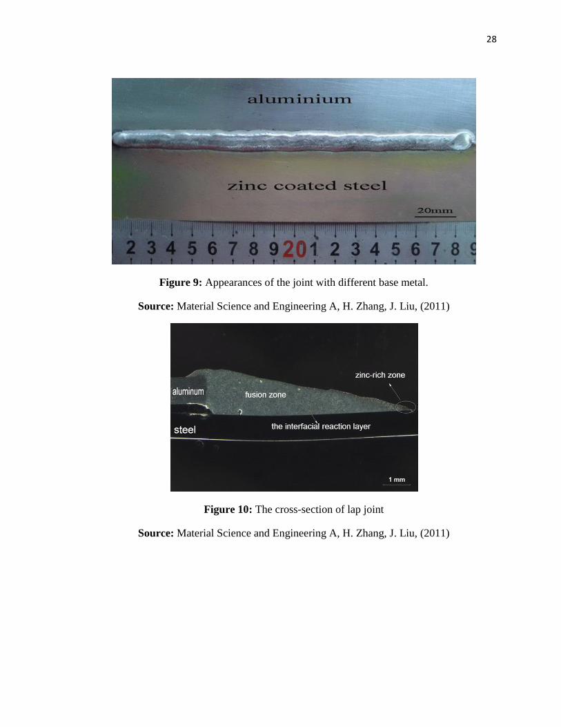
2.5.3 Weldability of Steel- Aluminum
A few papers have reported that the process of welding steel and aluminum is
possible to do. Although that the process is difficult, with the right parameter the welding
can be done. This is shown in Figure 9 in which the joints between galvanize steel and
alunimum sheets is made by the right heat input and the spreading degree of molten
aluminum on the steel surface. Then, Figure 10 shows the cross-section of the joint and the
liquid fillermetal spreading enough to form a good joint. (H. Zhang, J. Liu, 2011)
28
Figure 9: Appearances of the joint with different base metal.
Source: Material Science and Engineering A, H. Zhang, J. Liu, (2011)
Figure 10: The cross-section of lap joint
Source: Material Science and Engineering A, H. Zhang, J. Liu, (2011)