air conditioners technical data · 2019-05-09 · air conditioners outdoor air processing unit,...
TRANSCRIPT
FXMQ-MF
E E D E N 1 2 - 2 0 5
Air Conditioners
Outdoor a i r process ing unit , vent i lat ion and a i r process ing
Technical Data
FXMQ-MF
E E D E N 1 2 - 2 0 5
Air Conditioners
Outdoor a i r process ing unit , vent i lat ion and a i r process ing
Technical Data
• VRV ® Systems • Indoor Unit 1
• Indoor Unit • Outdoor air processing unit, ventilation and air processing • FXMQ-MF
TABLE OF CONTENTSFXMQ-MF
1 Features . . . . . . . . . . . . . . . . . . . . . . . . . . . . . . . . . . . . . . . . . . . . . . . . . . . . . . . . . . . . . 2
2 Specifications . . . . . . . . . . . . . . . . . . . . . . . . . . . . . . . . . . . . . . . . . . . . . . . . . . . . . . . 3
Technical Specifications . . . . . . . . . . . . . . . . . . . . . . . . . . . . . . . . . . . . . . . . . . . . . 3
Electrical Specifications . . . . . . . . . . . . . . . . . . . . . . . . . . . . . . . . . . . . . . . . . . . . . . 3
3 Safety device settings . . . . . . . . . . . . . . . . . . . . . . . . . . . . . . . . . . . . . . . . . . . . . 4
Safety Device Settings . . . . . . . . . . . . . . . . . . . . . . . . . . . . . . . . . . . . . . . . . . . . . . . 4
4 Options . . . . . . . . . . . . . . . . . . . . . . . . . . . . . . . . . . . . . . . . . . . . . . . . . . . . . . . . . . . . . . 5
Options . . . . . . . . . . . . . . . . . . . . . . . . . . . . . . . . . . . . . . . . . . . . . . . . . . . . . . . . . . . . . . . 5
5 Control systems . . . . . . . . . . . . . . . . . . . . . . . . . . . . . . . . . . . . . . . . . . . . . . . . . . . . 6
Control Systems . . . . . . . . . . . . . . . . . . . . . . . . . . . . . . . . . . . . . . . . . . . . . . . . . . . . . 6
6 Capacity tables . . . . . . . . . . . . . . . . . . . . . . . . . . . . . . . . . . . . . . . . . . . . . . . . . . . . . 7
Cooling/Heating Capacity Tables . . . . . . . . . . . . . . . . . . . . . . . . . . . . . . . . . . . . 7
7 Dimensional drawings . . . . . . . . . . . . . . . . . . . . . . . . . . . . . . . . . . . . . . . . . . . . 10
Dimensional Drawings . . . . . . . . . . . . . . . . . . . . . . . . . . . . . . . . . . . . . . . . . . . . . . 10
8 Centre of gravity . . . . . . . . . . . . . . . . . . . . . . . . . . . . . . . . . . . . . . . . . . . . . . . . . . . 12
Centre of Gravity . . . . . . . . . . . . . . . . . . . . . . . . . . . . . . . . . . . . . . . . . . . . . . . . . . . . 12
9 Piping diagrams . . . . . . . . . . . . . . . . . . . . . . . . . . . . . . . . . . . . . . . . . . . . . . . . . . . 13
Piping Diagrams . . . . . . . . . . . . . . . . . . . . . . . . . . . . . . . . . . . . . . . . . . . . . . . . . . . . 13
10 Wiring diagrams . . . . . . . . . . . . . . . . . . . . . . . . . . . . . . . . . . . . . . . . . . . . . . . . . . . 14
Wiring Diagrams - Single Phase . . . . . . . . . . . . . . . . . . . . . . . . . . . . . . . . . . . 14
11 Sound data . . . . . . . . . . . . . . . . . . . . . . . . . . . . . . . . . . . . . . . . . . . . . . . . . . . . . . . . . 15
Sound Pressure Spectrum . . . . . . . . . . . . . . . . . . . . . . . . . . . . . . . . . . . . . . . . . . 15
12 Fan characteristics . . . . . . . . . . . . . . . . . . . . . . . . . . . . . . . . . . . . . . . . . . . . . . . . 16
Fan Characteristics . . . . . . . . . . . . . . . . . . . . . . . . . . . . . . . . . . . . . . . . . . . . . . . . . 16
13 Operation range . . . . . . . . . . . . . . . . . . . . . . . . . . . . . . . . . . . . . . . . . . . . . . . . . . . 18
Operation Range . . . . . . . . . . . . . . . . . . . . . . . . . . . . . . . . . . . . . . . . . . . . . . . . . . . . 18
• Indoor Unit • Outdoor air processing unit, ventilation and air processing • FXMQ-MF
11
• VRV ® Systems • Indoor Unit2
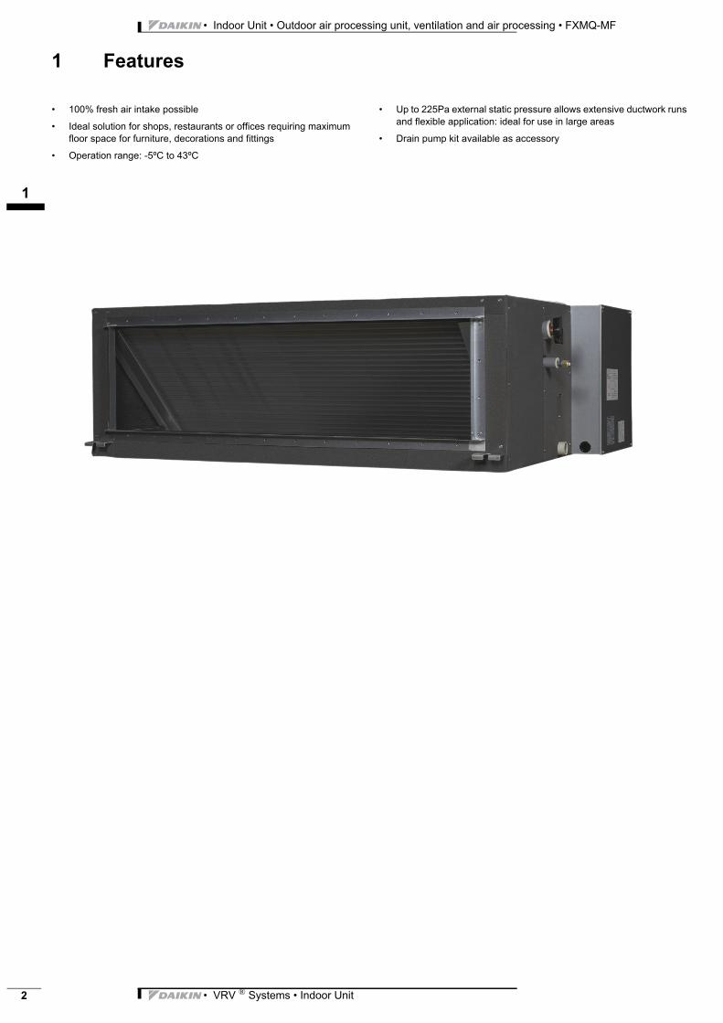
1 Features
VRV System FXMQ-MF Outdoor air • 100% fresh air intake possible
• Ideal solution for shops, restaurants or offices requiring maximum floor space for furniture, decorations and fittings
• Operation range: -5ºC to 43ºC
• Up to 225Pa external static pressure allows extensive ductwork runs and flexible application: ideal for use in large areas
• Drain pump kit available as accessory
3
12
• VRV ® Systems • Indoor Unit 3
• Indoor Unit • Outdoor air processing unit, ventilation and air processing • FXMQ-MF
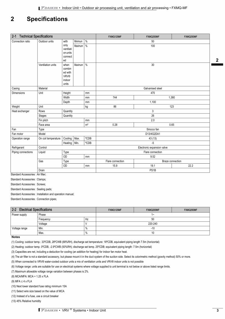
2 Specifications
Standard Accessories : Air filter;
Standard Accessories : Clamps;
Standard Accessories : Screws;
Standard Accessories : Sealing pads;
Standard Accessories : Installation and operation manual;
Standard Accessories : Connection pipes;
Notes
(1) Cooling: outdoor temp.: 33ºCDB, 28ºCWB (68%RH), discharge set temperature: 18ºCDB, equivalent piping length 7.5m (horizontal)
(2) Heating: outdoor temp. 0ºCDB, -2.9ºCWB (50%RH); discharge set temp. 25ºCDB; equivalent piping length: 7.5m (horizontal)
(3) Capacities are net, including a deduction for cooling (an addition for heating) for indoor fan motor heat.
(4) The air filter is not a standard accessory, but please mount it in the duct system of the suction side. Select its colorimetric method (gravity method) 50% or more.
(5) When connected to VRV® water-cooled outdoor units a mix of ventilation units and VRV® indoor units is not possible
(6) Voltage range: units are suitable for use on electrical systems where voltage supplied to unit terminal is not below or above listed range limits.
(7) Maximum allowable voltage range variation between phases is 2%.
(8) MCA/MFA: MCA = 1.25 x FLA
(9) MFA ≤ 4 x FLA
(10) Next lower standard fuse rating minimum 15A
(11) Select wire size based on the value of MCA
(12) Instead of a fuse, use a circuit breaker
(13) 45% Relative humidity
2-1 Technical Specifications FXMQ125MF FXMQ200MF FXMQ250MF
Connection ratio Outdoor units with only ventilation units connected
Minimum % 50
Maximum % 100
Ventilation units when combined with VRV® indoor units
Maximum % 30
Casing Material Galvanised steel
Dimensions Unit Height mm 470
Width mm 744 1,380
Depth mm 1,100
Weight Unit kg 86 123
Heat exchanger Rows Quantity 3
Stages Quantity 26
Fin pitch mm 2.0
Face area m² 0.28 0.65
Fan Type Sirocco fan
Fan motor Model D13/4G2DA1
Operation range On coil temperature Cooling Max. ºCDB 43 (13)
Heating Min. ºCDB -5
Refrigerant Control Electronic expansion valve
Piping connections Liquid Type Flare connection
OD mm 9.52
Gas Type Flare connection Braze connection
OD mm 15.9 19.1 22.2
Drain PS1B
2-2 Electrical Specifications FXMQ125MF FXMQ200MF FXMQ250MF
Power supply Phase 1~
Frequency Hz 50
Voltage V 220-240
Voltage range Min. % -10
Max. % 10
• Indoor Unit • Outdoor air processing unit, ventilation and air processing • FXMQ-MF
13
• VRV ® Systems • Indoor Unit4
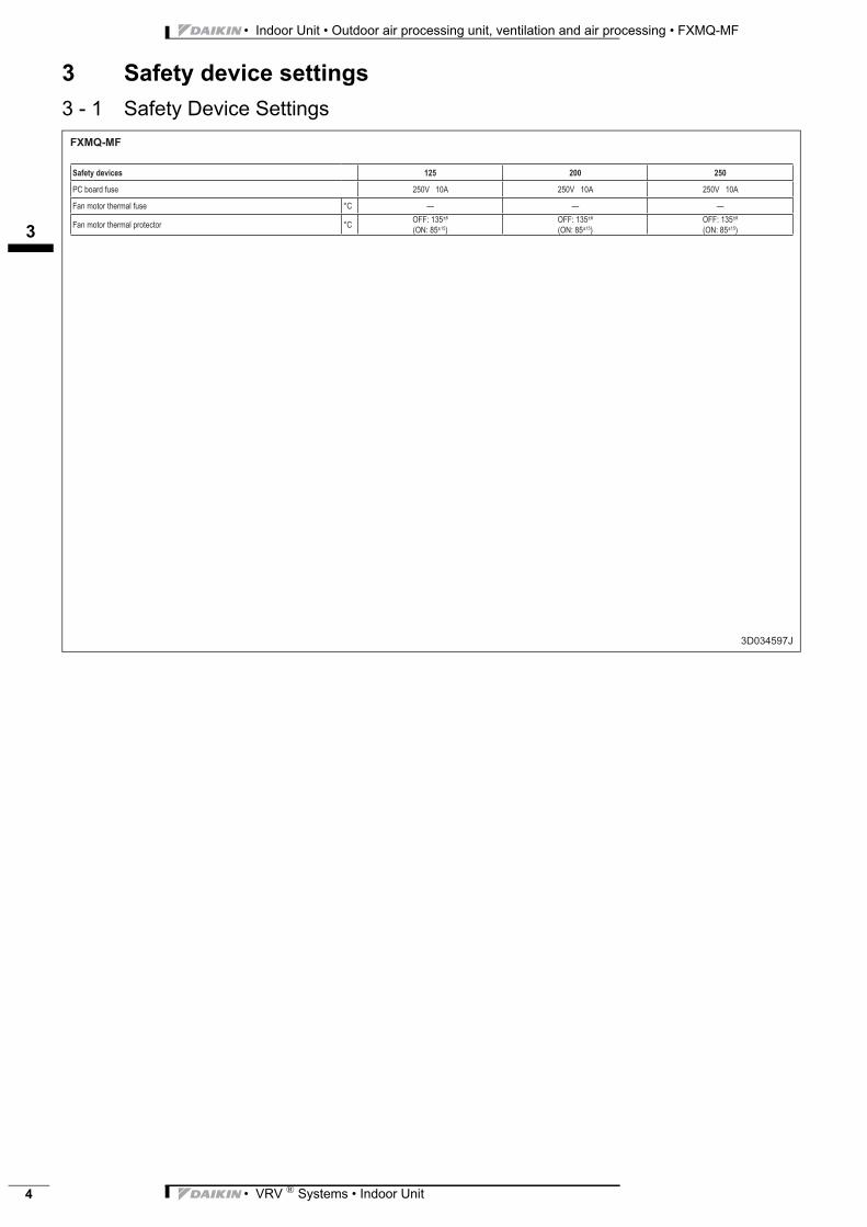
3 Safety device settings
3 - 1 Safety Device Settings
3
14
• VRV ® Systems • Indoor Unit 5
• Indoor Unit • Outdoor air processing unit, ventilation and air processing • FXMQ-MF
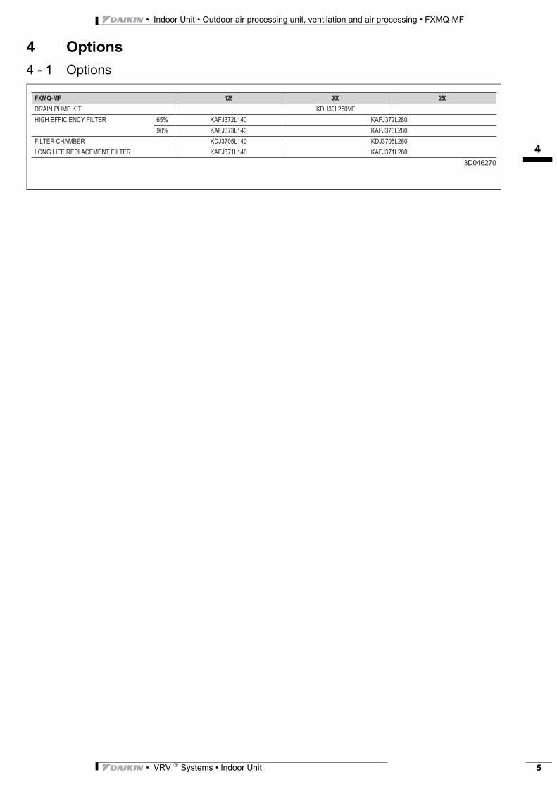
4 Options
4 - 1 Options
������� �� � �
������������ �� �������
���������������������� ��� ���� ������ ���� ������
�� ���� � ���� ���� � ����
����������!�� ��� ������� ��� �������
�"������������������������� ���� ������ ���� ������
��������
• Indoor Unit • Outdoor air processing unit, ventilation and air processing • FXMQ-MF
15
• VRV ® Systems • Indoor Unit6
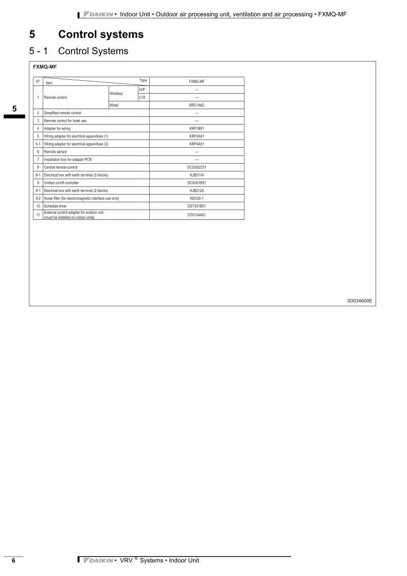
5 Control systems
5 - 1 Control Systems
3
16
• VRV ® Systems • Indoor Unit 7
• Indoor Unit • Outdoor air processing unit, ventilation and air processing • FXMQ-MF
6 Capacity tables
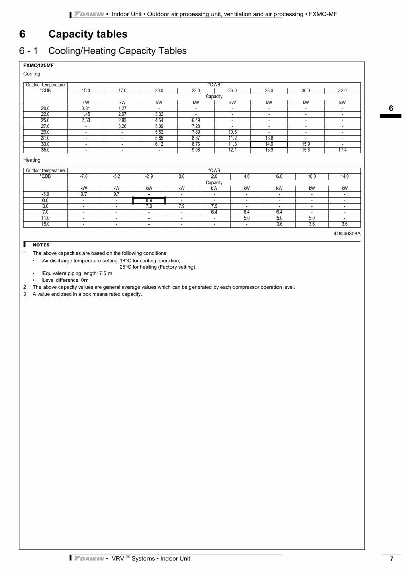
6 - 1 Cooling/Heating Capacity TablesFXMQ125MF
Cooling
Heating
4D046308A
NOTES
1 The above capacities are based on the following conditions:
• Air discharge temperature setting: 18°C for cooling operation,
25°C for heating (Factory setting)
• Equivalent piping length: 7.5 m
• Level difference: 0m
2 The above capacity values are general average values which can be generated by each compressor operation level.
3 A value enclosed in a box means rated capacity.
Outdoor temperature °CWB°CDB 15.0 17.0 20.0 23.0 26.0 28.0 30.0 32.0
CapacitykW kW kW kW kW kW kW kW
20.0 0.81 1.27 - - - - - -22.0 1.45 2.07 3.32 - - - - -25.0 2.53 2.83 4.54 6.49 - - - -27.0 - 3.26 5.09 7.28 - - - -29.0 - - 5.52 7.89 10.6 - - -31.0 - - 5.85 8.37 11.2 13.6 - -33.0 - - 6.12 8.76 11.8 14.0 15.9 -35.0 - - - 9.08 12.1 13.9 15.8 17.4
Outdoor temperature °CWB°CDB -7.0 -5.2 -2.9 0.0 2.0 4.0 6.0 10.0 14.0
CapacitykW kW kW kW kW kW kW kW kW
-5.0 9.7 9.7 - - - - - - -0.0 - - 8.9 - - - - - -3.0 - - 7.9 7.9 7.9 - - - -7.0 - - - - 6.4 6.4 6.4 - -
11.0 - - - - - 5.0 5.0 5.0 -15.0 - - - - - - 3.6 3.6 3.6
• Indoor Unit • Outdoor air processing unit, ventilation and air processing • FXMQ-MF
16
• VRV ® Systems • Indoor Unit8
6 Capacity tables
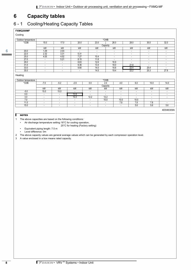
6 - 1 Cooling/Heating Capacity TablesFXMQ200MF
Cooling
Heating
4D046309A
NOTES
1 The above capacities are based on the following conditions:
• Air discharge temperature setting:18°C for cooling operation,
25°C for heating (Factory setting)
• Equivalent piping length: 7.5 m
• Level difference: 0m
2 The above capacity values are general average values which can be generated by each compressor operation level.
3 A value enclosed in a box means rated capacity.
Outdoor temperature °CWB°CDB 15.0 17.0 20.0 23.0 26.0 28.0 30.0 32.0
CapacitykW kW kW kW kW kW kW kW
20.0 1.29 2.03 - - - - - -22.0 2.32 3.31 5.31 - - - - -25.0 4.05 4.52 7.27 10.4 - - - -27.0 - 5.21 8.15 11.6 - - - -29.0 - - 8.83 12.6 16.9 - - -31.0 - - 9.36 13.4 18.0 21.8 - -33.0 - - 9.80 14.0 18.8 22.4 25.4 -35.0 - - - 14.5 19.4 22.2 25.3 27.8
Outdoor temperature °CWB°CDB -7.0 -5.2 -2.9 0.0 2.0 4.0 6.0 10.0 14.0
CapacitykW kW kW kW kW kW kW kW kW
-5.0 15.0 15.0 - - - - - - -0.0 - - 13.9 - - - - - -3.0 - - 12.2 12.2 12.2 - - - -7.0 - - - - 10.0 10.0 10.0 -
11.0 - - - - - 7.8 7.8 7.8 -15.0 - - - - - - 5.6 5.6 5.6
3
16
• VRV ® Systems • Indoor Unit 9
• Indoor Unit • Outdoor air processing unit, ventilation and air processing • FXMQ-MF
6 Capacity tables
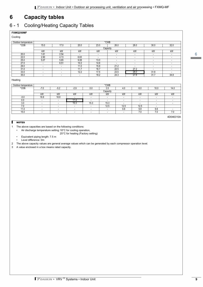
6 - 1 Cooling/Heating Capacity TablesFXMQ250MF
Cooling
Heating
4D046310A
NOTES
1 The above capacities are based on the following conditions:
• Air discharge temperature setting:18°C for cooling operation,
25°C for heating (Factory setting)
• Equivalent piping length: 7.5 m
• Level difference: 0m
2 The above capacity values are general average values which can be generated by each compressor operation level.
3 A value enclosed in a box means rated capacity.
Outdoor temperature °CWB°CDB 15.0 17.0 20.0 23.0 26.0 28.0 30.0 32.0
CapacitykW kW kW kW kW kW kW kW
20.0 1.61 2.54 - - - - - -22.0 2.90 4.13 6.63 - - - - -25.0 5.07 5.65 9.08 13.0 - - - -27.0 - 6.51 10.2 14.6 - - - -29.0 - - 11.0 15.8 21.2 - - -31.0 - - 11.7 16.7 22.5 27.2 - -33.0 - - 12.2 17.5 23.5 28.0 31.8 -35.0 - - - 18.2 24.3 27.8 31.7 34.8
Outdoor temperature °CWB°CDB -7.0 -5.2 -2.9 0.0 2.0 4.0 6.0 10.0 14.0
CapacitykW kW kW kW kW kW kW kW kW
-5.0 18.8 18.8 - - - - - - -0.0 - - 17.4 - - - - - -3.0 - - 15.3 15.3 15.3 - - - -7.0 - - - - 12.5 12.5 12.5 -
11.0 - - - - - 9.8 9.8 9.8 -15.0 - - - - - - 7.0 7.0 7.0

• Indoor Unit • Outdoor air processing unit, ventilation and air processing • FXMQ-MF
17
• VRV ® Systems • Indoor Unit10
7 Dimensional drawings
7 - 1 Dimensional Drawings���������
�������
NOTES
� �$%&'($)�$*�+)(',/�)&:;�<=&';/>��$)'?$=�@$A�/+?*&%;E
� $+)'�'F;�&(?�*(=';?�&'�'F;�/+%'($)�/(G;E�
HI;=;%'�('/�%$=$?(:;'F$G�HJ?&K('L�:;'F$GM�����$?�:$?;ME
�? �&:; �;/%?(<'($)
� �(N+(G�<(<;�%$));%'($) P� E��*=&?;�%$));%'($)
� �&/�<(<;�%$));%'($) P���E �*=&?;�%$));%'($)
�?&()�<(<;�%$));%'($) �I�!��)';?)&=�'F?;&G&Q$?�G(&E�P� E � R()$?�G(&E�P� �E �
� �$)'?$=�@$A
� �?$+)G�';?:()&= ��H�)/(G;�%$)'?$=�@$AM
� �&:;�<=&'; �$';��
� �$S;?�/+<<=L�S(?()J�%$));%'($)
� �?&)/:(//($)�S(?()J�%$));%'($)
�&)J;?�@?&%T;' ��
�� �(/%F&?J;�%$:<&)($)�*=&)J;
�� U&';?�/+<<=L�<$?'
H�==�&?$+)GM
���V�P��E��F$=;
HI;?K(%;�/<&%;M
�)/<;%'($)�F$=;�����$?�:$?;
����
$?�:
$?;
�A��
�X��
�
���
���
HI;?
K(%;
�/<&
%;M
�����$?�:$?;
����
�<<
?$AE
���
�
�(/%F&?J;�/(G;
���(;S
I+%'($)�/(G;�H�$';��M
A��
�X �
�
����
���
��
���
��
���(;S
H�==�&?$+)GM
���V���F$=; � �
���
�A���X���
���
��
��
���
H�==�&?$+)GM
���V�P��F$=;
� ����
�A���X���
��
��
�
A��
�X �
�
��
� �
�
�
FXMQ125MF
3D046155
Nr Name Description
1 VRV D.P. Unit C. duct type
2 Filter chamber
3 High-efficiency filter
4 Long-life replacement filter
5 Drain pump kit Built-in
6 Drain pipe connection (drain pump kit)
VP25 (O.D. ø 32, I.D. ø 25)
7 Water supply port
8 Drain hose Attached to drain pump kit
Inspection hole 600 or more
650
or m
ore
5x10
0=50
0
744
(Ser
vice
spa
ce)
1100
1148
App
rox.
30
0
A
79529
285
456
8
A View
564
5x100=500 223
200
330
360
630600
5x100=500
(0~2
50)
360
330
3x10
0=30
0
300 or less
222 22
2~47
2
250
20 - ø4.7 hole(All around)
16 - ø8 hole(All around)
744
685
690
or m
ore
(Ser
vice
spa
ce)
222
3x10
0=30
0
594
20 - ø7 hole
(All around)
3
17
• VRV ® Systems • Indoor Unit 11
• Indoor Unit • Outdoor air processing unit, ventilation and air processing • FXMQ-MF
7 Dimensional drawings
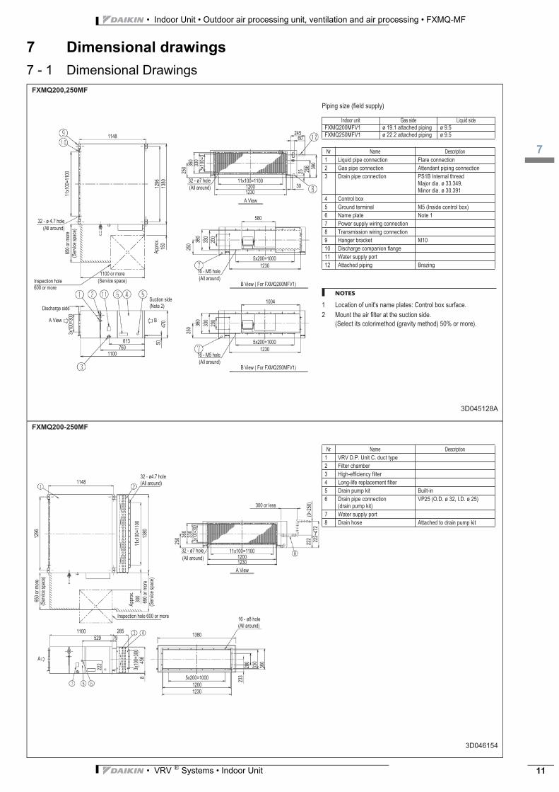
7 - 1 Dimensional DrawingsFXMQ200,250MF
3D045128A
Piping size (field supply)
NOTES
1 Location of unit's name plates: Control box surface.
2 Mount the air filter at the suction side.
(Select its colorimethod (gravity method) 50% or more).
Indoor unit Gas side Liquid side
FXMQ200MFV1 ø 19.1 attached piping ø 9.5
FXMQ250MFV1 ø 22.2 attached piping ø 9.5
Nr Name Description
1 Liquid pipe connection Flare connection
2 Gas pipe connection Attendant piping connection
3 Drain pipe connection PS1B Internal threadMajor dia. ø 33.349,Minor dia. ø 30.391
4 Control box
5 Ground terminal M5 (Inside control box)
6 Name plate Note 1
7 Power supply wiring connection
8 Transmission wiring connection
9 Hanger bracket M10
10 Discharge companion flange
11 Water supply port
12 Attached piping Brazing
(All around)
32 - ø 4.7 hole
(Service space)Inspection hole 600 or more
650
or m
ore
11x1
00=1
100
1296
1380
(Ser
vice
spa
ce)
1100 or more
1148
App
rox.
15
0
Discharge side
A View
Suction side (Note 2)
3x10
0=30
0
1100760
613
470
50
A View
(All around)
16 - M5 hole1230
5x200=1000
250
360
330
200
(All around)
32 - ø7 hole
12301200
11x100=1100
25
360
330
3x10
0=3
61
296 39
0
3025
0
1004
B View ( For FXMQ250MFV1)
(All around)
16 - M5 hole1230
5x200=1000
250
360
330
200
580
B View ( For FXMQ200MFV1)
B
24560
FXMQ200-250MF
3D046154
Nr Name Description
1 VRV D.P. Unit C. duct type
2 Filter chamber
3 High-efficiency filter
4 Long-life replacement filter
5 Drain pump kit Built-in
6 Drain pipe connection (drain pump kit)
VP25 (O.D. ø 32, I.D. ø 25)
7 Water supply port
8 Drain hose Attached to drain pump kit
Inspection hole 600 or more
650
or m
ore
11x1
00=1
100
1380
(Ser
vice
spa
ce)
1100
1148
App
rox.
30
0
A
79529
285
456
8
A View
1200
5x200=1000
233
200
330
360
12301200
11x100=1100
(0~2
50)
360
330
3x10
0=30
0
300 or less
222 22
2~47
2
250
32 - ø4.7 hole(All around)
16 - ø8 hole(All around)
1380
1296
690
or m
ore
(Ser
vice
spa
ce)
222
3x10
0=30
0
1230
32 - ø7 hole
(All around)
• Indoor Unit • Outdoor air processing unit, ventilation and air processing • FXMQ-MF
18
• VRV ® Systems • Indoor Unit12
8 Centre of gravity
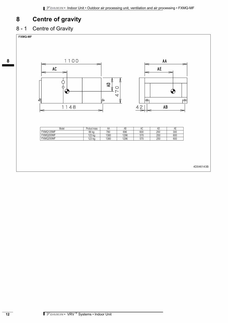
8 - 1 Centre of Gravity������
�������
$G;= �?$G+%'�:&// �� �! �� �� �����������������������
���TJ ��� � � ��� ��� ���� �TJ � �� �� � ��� ��� ����� �TJ � �� �� � ��� ��� ���
3
19
• VRV ® Systems • Indoor Unit 13
• Indoor Unit • Outdoor air processing unit, ventilation and air processing • FXMQ-MF
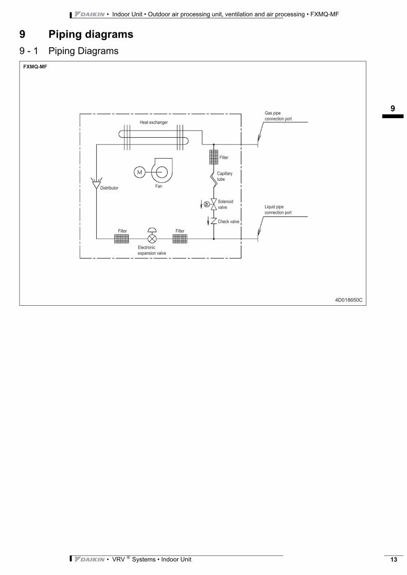
9 Piping diagrams
9 - 1 Piping Diagrams

• Indoor Unit • Outdoor air processing unit, ventilation and air processing • FXMQ-MF
110
• VRV ® Systems • Indoor Unit14
10 Wiring diagrams
10 - 1 Wiring Diagrams - Single Phase
�
3
111
• VRV ® Systems • Indoor Unit 15
• Indoor Unit • Outdoor air processing unit, ventilation and air processing • FXMQ-MF
11 Sound data
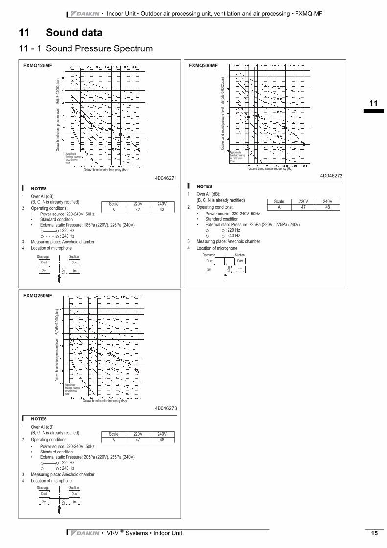
11 - 1 Sound Pressure Spectrum
�������
�����
� "K;?��==�HG!M>H!R��R���(/�&=?;&GL�?;%'(*(;GM
� "<;?&'()J�%$)G('$)/>
� �$S;?�/$+?%;>����V����������� I'&)G&?G�%$)G('($)� �A';?)&=�/'&'(%��?;//+?;>�����&�H����MR�����&�H����M
>�������>�������
;&/+?()J�<=&%;>��);%F$(%�%F&:@;?
� �$%&'($)�$*�:(%?$<F$);
"%'
&K;�
@&)G
�/$+
)G�<
?;//
+?;�
=;K;
=����G
!H�
G!X�
E���
��@&
?M
"%'&K;�@&)G�%;)';?�*?;N+;)%L�H��M
�<<?$A(:&';�'F?;/F$=G�F;&?()J�*$?�%$)'()+$+/�)$(/;
���������
I%&=; ���� ����� �� �
�(/%F&?J; I+%'($)
�+%'�+%'
�:�:
�R�:
4D046272
NOTES
1 Over All (dB):
(B, G, N is already rectified)
2 Operating conditons:
• Power source: 220-240V 50Hz• Standard condition• External static Pressure: 225Pa (220V), 275Pa (240V)
: 220 Hz: 240 Hz
3 Measuring place: Anechoic chamber
4 Location of microphone
Oct
ave
band
sou
nd p
ress
ure
leve
l d
B(0
dB=0
.000
2μba
r)
Octave band center frequency (Hz)
Approximate threshold hearing for continuous noise
FXMQ200MF
Scale 220V 240VA 47 48
Discharge Suction
DuctDuct
1m2m
1,5m
4D046273
NOTES
1 Over All (dB):
(B, G, N is already rectified)
2 Operating conditons:
• Power source: 220-240V 50Hz• Standard condition• External static Pressure: 205Pa (220V), 255Pa (240V)
: 220 Hz: 240 Hz
3 Measuring place: Anechoic chamber
4 Location of microphone
Oct
ave
band
sou
nd p
ress
ure
leve
l d
B(0
dB=0
.000
2μba
r)
Octave band center frequency (Hz)
Approximate threshold hearing for continuous noise
FXMQ250MF
Scale 220V 240VA 47 48
Discharge Suction
DuctDuct
1m2m
1,5m
• Indoor Unit • Outdoor air processing unit, ventilation and air processing • FXMQ-MF
112
• VRV ® Systems • Indoor Unit16
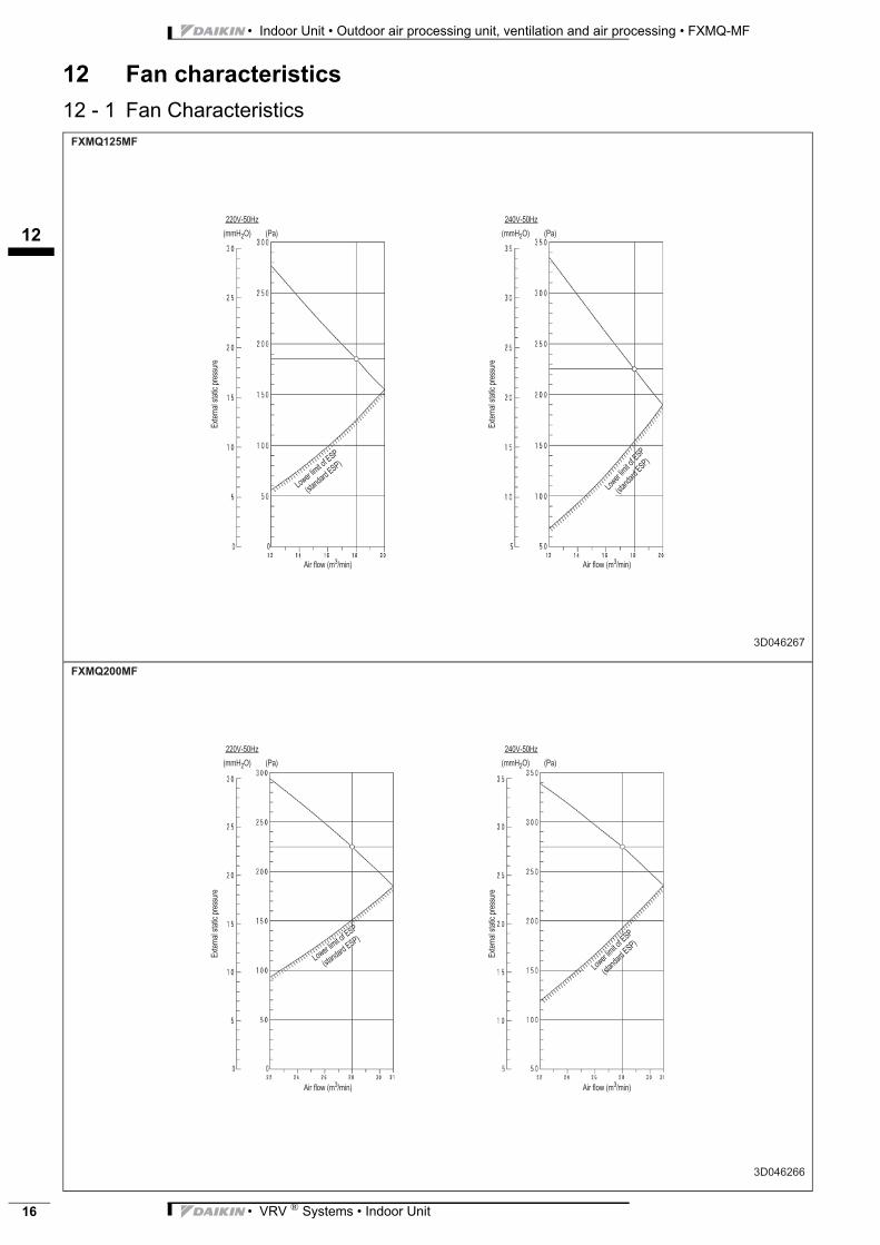
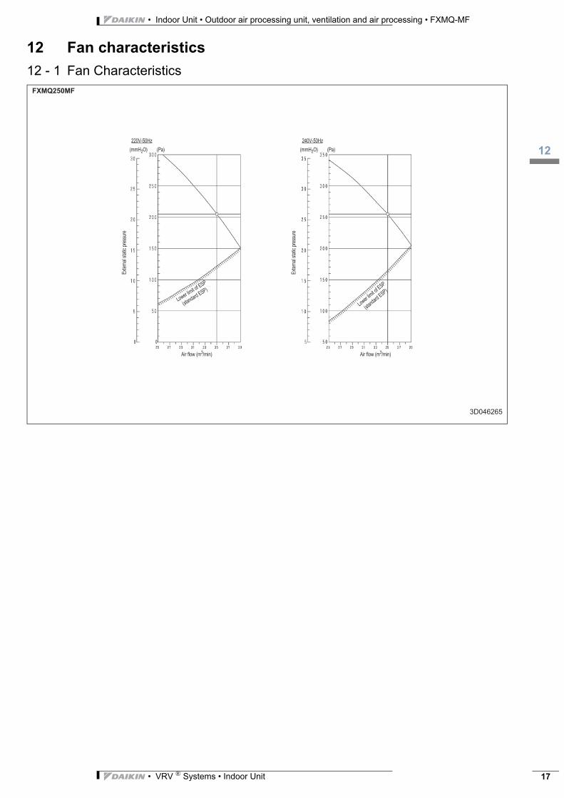
12 Fan characteristics
12 - 1 Fan Characteristics���������
��������
����V���� ����V�����
A';?
)&=�/
'&'(%
�<?;
//+?
;
�A'
;?)&
=�/'&
'(%�<
?;//
+?;
H::��"M��������H�&M H::��"M��������H�&M
�(?�*=$S�H: �:()M �(?�*=$S�H: �:()M
�$S;?
�=(:('�$
*��I�
H/'&)
G&?G
��I�M
�$S;?�
=(:('�$
*��I�
H/'&)G
&?G��I�M
FXMQ200MF
3D046266
220V-50Hz 240V-50Hz
Ext
erna
l sta
tic p
ress
ure
Ext
erna
l sta
tic p
ress
ure
(mmH2O) (Pa) (mmH2O) (Pa)
Air flow (m3/min) Air flow (m3/min)
Lower
limit o
f ESP
(stan
dard
ESP)
Lower limit of ESP
(standard
ESP)
3
112
• VRV ® Systems • Indoor Unit 17
• Indoor Unit • Outdoor air processing unit, ventilation and air processing • FXMQ-MF
12 Fan characteristics
12 - 1 Fan Characteristics��������
�������
����V���� ����V����
�A'
;?)&
=�/'&
'(%�<
?;//
+?;
�A'
;?)&
=�/'&
'(%�<
?;//
+?;
H::��"M��������H�&M H::��"M��������H�&M
�(?�*=$S�H: �:()M �(?�*=$S�H: �:()M
�$S;?�
=(:('�$
*��I�
H/'&)
G&?G��I�M
�$S;?�=(:('�$
*��I�
H/'&)G&?G��I�M
• Indoor Unit • Outdoor air processing unit, ventilation and air processing • FXMQ-MF
113
• VRV ® Systems • Indoor Unit18
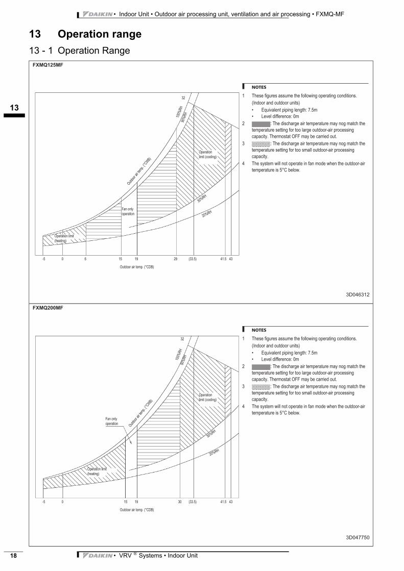
13 Operation range
13 - 1 Operation Range���������
�������
NOTES
� �F;/;�*(J+?;/�&//+:;�'F;�*$==$S()J�$<;?&'()J�%$)G('($)/E
H�)G$$?�&)G�$+'G$$?�+)('/M
� �N+(K&=;)'�<(<()J�=;)J'F>��E�:
� �;K;=�G(**;?;)%;>��:
� >��F;�G(/%F&?J;�&(?�';:<;?&'+?;�:&L�)$J�:&'%F�'F;�
';:<;?&'+?;�/;''()J�*$?�'$$�=&?J;�$+'G$$?V&(?�<?$%;//()J�
%&<&%('LE��F;?:$/'&'�"���:&L�@;�%&??(;G�$+'E
>��F;�G(/%F&?J;�&(?�';:<;?&'+?;�:&L�)$J�:&'%F�'F;�
';:<;?&'+?;�/;''()J�*$?�'$$�/:&==�$+'G$$?V&(?�<?$%;//()J�
%&<&%('LE
� �F;�/L/';:�S(==�)$'�$<;?&';�()�*&)�:$G;�SF;)�'F;�$+'G$$?V&(?�
';:<;?&'+?;�(/�����@;=$SE
"<;?&'($)�=(:('�HF;&'()JM
�&)�$)=L�$<;?&'($)
"+'G$$?�&(?�';:<E�H���!M
"<;?&'($)�=(:('�H%$$=()JM
"+'G$
$?�&
(?�';
:<E
�H��U
!M�
����
��
���
��
����
�����
V� � � �� � � H E�M ��E� �
�
�������
�������
NOTES
� �F;/;�*(J+?;/�&//+:;�'F;�*$==$S()J�$<;?&'()J�%$)G('($)/E
H�)G$$?�&)G�$+'G$$?�+)('/M
� �N+(K&=;)'�<(<()J�=;)J'F>��E�:
� �;K;=�G(**;?;)%;>��:
� >��F;�G(/%F&?J;�&(?�';:<;?&'+?;�:&L�)$J�:&'%F�'F;�
';:<;?&'+?;�/;''()J�*$?�'$$�=&?J;�$+'G$$?V&(?�<?$%;//()J�
%&<&%('LE��F;?:$/'&'�"���:&L�@;�%&??(;G�$+'E
>��F;�G(/%F&?J;�&(?�';:<;?&'+?;�:&L�)$J�:&'%F�'F;�
';:<;?&'+?;�/;''()J�*$?�'$$�/:&==�$+'G$$?V&(?�<?$%;//()J�
%&<&%('LE
� �F;�/L/';:�S(==�)$'�$<;?&';�()�*&)�:$G;�SF;)�'F;�$+'G$$?V&(?�
';:<;?&'+?;�(/�����@;=$SE
"<;?&'($)�=(:('�HF;&'()JM
�&)�$)=L�$<;?&'($)
"+'G$$?�&(?�';:<E�H���!M
"<;?&'($)�=(:('�H%$$=()JM
"+'G$
$?�&
(?�';
:<E
�H��U
!M�
����
��
���
��
����
�����
V� � �� � � H E�M ��E� �
�
3
113
• VRV ® Systems • Indoor Unit 19
• Indoor Unit • Outdoor air processing unit, ventilation and air processing • FXMQ-MF
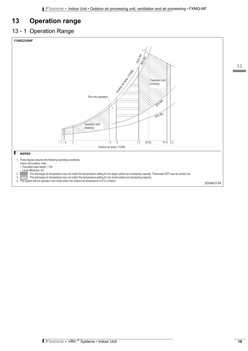
13 Operation range
13 - 1 Operation Range
3D046313A
FXMQ250MF
NOTES
1.
2.
3.
4.

Naamloze Vennootschap - Zandvoordestraat 300, B-8400 Oostende - Belgium - www.daikin.eu - BE 0412 120 336 - RPR Oostende EED
EN12
-205
• C
D •
02/1
2 • C
opyr
ight
Dai
kin
The
pres
ent p
ublic
atio
n su
pers
edes
EED
EN11
-205
Prep
ared
in B
elgi
um b
y La
nnoo
(ww
w.la
nnoo
prin
t.be)
, a c
ompa
ny w
hose
con
cern
fo
r the
env
ironm
ent i
s se
t in
the
EMAS
and
ISO
140
01 s
yste
ms.
Resp
onsi
ble
Ed
itor
: Dai
kin
Euro
pe
N.V
., Z
and
voor
des
traa
t 30
0, B
-840
0 O
oste
nde
Daikin’s unique position as a manufacturer of air conditioning equipment, compressors and refrigerants has led to its close involvement in environmental issues. For several years Daikin has had the intention to become a leader in the provision of products that have limited impact on the environment. This challenge demands the eco design and development of a wide range of products and an energy management system, resulting in energy conservation and a reduction of waste.
Daikin products are distributed by:
VRV® products are not within the scope of the Eurovent certification programme.
The present publication is drawn up by way of information only and does not constitute an offer binding upon Daikin Europe N.V.. Daikin Europe N.V. has compiled the content of this publication to the best of its knowledge. No express or implied warranty is given for the completeness, accuracy, reliability or fitness for particular purpose of its content and the products and services presented therein. Specifications are subject to change without prior notice. Daikin Europe N.V. explicitly rejects any liability for any direct or indirect damage, in the broadest sense, arising from or related to the use and/or interpretation of this publication. All content is copyrighted by Daikin Europe N.V..