air conditioning system - mike's 94 supra turbo
TRANSCRIPT

AIR CONDITIONING SYSTEM
AC–1

GENERAL DESCRIPTIONNEW AIR CONDITIONING SYSTEM WITHHFC134a
Refrigerant CFC 12 (R 12), previously used in automobiles’air conditioning systems is believed to contribute towards thedepletion the earth’s ozone layer. The ozone layer help toprotect us against the harmful ultraviolet rays of the sun.
A newly developed refrigerant, HFC 134a (R 134 a), does notthe destroy the ozone layer.
PRECAUTIONS FOR SERVICINGHFC134a AIR CONDITIONINGS1. USE OF NEW REFRIGERANT HFC134a
The very different characteristics of refrigerants HFC134aand CFC12 have determined the design of their respectiveair conditioning systems. Under no circumstances allowCFC12 to enter an HFC134a system, or vice versa, becauseserious damage could occur.
2. USE OF PROPER COMPRESSOR OILCompressor oil used in conventional CFC12 air conditioningsystems cannot be used in HFC134a air conditioning sys-tems.Always use genuine Toyota R134a air conditioning oil ND–OIL 8, made expressly for use with HFC134a.NOTICE: Compressor oil (ND–OIL 8) for HFC134a use ad-versely affects acrylic resin, so take care not to spill orspray any compressor oil.
If even a small amount of the wrong oil is changed, it will resultin clouding of the refrigerant.A large amount will cause the compressor to seize up.
AC–2–AIR CONDITIONING SYSTEM GENERAL DESCRIPTION
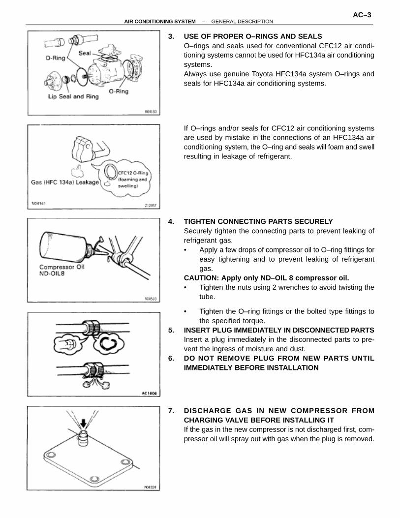
3. USE OF PROPER O–RINGS AND SEALSO–rings and seals used for conventional CFC12 air condi-tioning systems cannot be used for HFC134a air conditioningsystems.Always use genuine Toyota HFC134a system O–rings andseals for HFC134a air conditioning systems.
If O–rings and/or seals for CFC12 air conditioning systemsare used by mistake in the connections of an HFC134a airconditioning system, the O–ring and seals will foam and swellresulting in leakage of refrigerant.
4. TIGHTEN CONNECTING PARTS SECURELYSecurely tighten the connecting parts to prevent leaking ofrefrigerant gas.• Apply a few drops of compressor oil to O–ring fittings for
easy tightening and to prevent leaking of refrigerantgas.
CAUTION: Apply only ND–OIL 8 compressor oil.• Tighten the nuts using 2 wrenches to avoid twisting the
tube.
• Tighten the O–ring fittings or the bolted type fittings tothe specified torque.
5. INSERT PLUG IMMEDIATELY IN DISCONNECTED PARTSInsert a plug immediately in the disconnected parts to pre-vent the ingress of moisture and dust.
6. DO NOT REMOVE PLUG FROM NEW PARTS UNTILIMMEDIATELY BEFORE INSTALLATION
7. DISCHARGE GAS IN NEW COMPR ESSOR FROMCHARGING VALVE BEFORE INSTALLING ITIf the gas in the new compressor is not discharged first, com-pressor oil will spray out with gas when the plug is removed.
–AIR CONDITIONING SYSTEM GENERAL DESCRIPTIONAC–3

SERVICE TOOLS FOR HFC134a AIRCONDITIONING
When servicing HFC134a air conditioning systems alwaysuse the HFC134a dedicated manifold gauges, gas leak de-tector and vacuum pump adaptor.
1. USE MANIFOLD GAUGES FOR HFC134a AIRCONDITIONINGAlways use HFC134a dedicated manifold gauges to preventCFC 12 and CFC 12 compressor oil contaminating theHFC134a system.
2. USE HFC134a GAS LEAK DETECTORSimilarly, always use an HFC134a dedicated leak detector.The CFC12 leak detector is not sufficiently sensitive.
3. USE VACUUM PUMP ADAPTERBy connecting a vacuum pump adapter, the vacuum pumpcan be used for both HFC134a and CFC12 air conditioningsystems.The vacuum pump adaptor has an internal magnetic valve.When evacuation is completed and the vacuum pump switchis turned off, the magnetic valve opens allowing the introduc-tion atmospheric air into the manifold gauges to prevent theback flow of oil from the vacuum pump into the gauge hose.CAUTION:Be sure to turn off the manifold gauge valve immediatelyafter evacuating the system. Then you may switch off thevacuum pump. If this order is reversed, the line will betemporarily open to atmosphere.
AC–4–AIR CONDITIONING SYSTEM GENERAL DESCRIPTION
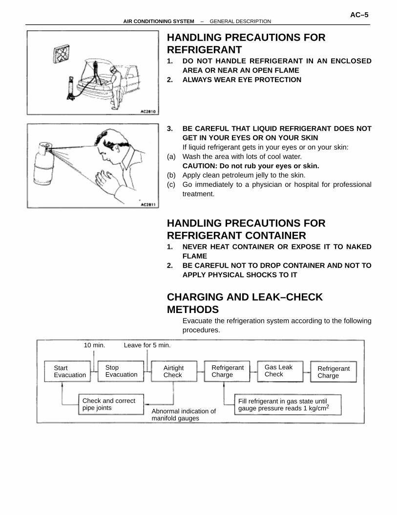
HANDLING PRECAUTIONS FORREFRIGERANT1. DO NOT HANDLE REFRIGERANT IN AN ENCLOSED
AREA OR NEAR AN OPEN FLAME2. ALWAYS WEAR EYE PROTECTION
3. BE CAREFUL THAT LIQUID REFRIGERANT DOES NOTGET IN YOUR EYES OR ON YOUR SKINIf liquid refrigerant gets in your eyes or on your skin:
(a) Wash the area with lots of cool water.CAUTION: Do not rub your eyes or skin.
(b) Apply clean petroleum jelly to the skin.(c) Go immediately to a physician or hospital for professional
treatment.
HANDLING PRECAUTIONS FORREFRIGERANT CONTAINER1. NEVER HEAT CONTAINER OR EXPOSE IT TO NAKED
FLAME2. BE CAREFUL NOT TO DROP CONTAINER AND NOT TO
APPLY PHYSICAL SHOCKS TO IT
CHARGING AND LEAK–CHECKMETHODS
Evacuate the refrigeration system according to the followingprocedures.
StartEvacuation
Stop Evacuation
AirtightCheck
RefrigerantCharge
RefrigerantCharge
Gas LeakCheck
Check and correctpipe joints
Fill refrigerant in gas state untilgauge pressure reads 1 kg/cm2
Abnormal indication ofmanifold gauges
10 min. Leave for 5 min.
–AIR CONDITIONING SYSTEM GENERAL DESCRIPTIONAC–5

CAUTION:• Be sure to connect both the high and low pressure
quick–connectors onto the A/C system when evacuating.If only one side is connected, the system would be opento atmosphere through the other connector, making itimpossible to maintain vacuum.
• Be sure to turn off the manifold gauge valve immediatelyafter evacuating the system. Then you may switch off thevacuum pump.
PRECAUTIONS WHEN CHARGINGREFRIGERANT1. DO NOT OPERATE COMPRESSOR WITHOUT ENOUGH
REFRIGERANT IN REFRIGERANT SYSTEMIf there is not enough refrigerant in the refrigerant system, oillubrication will be insufficient and compressor burnout mayoccur, so take care to avoid this.
2. DO NOT OPEN HIGH PRESSURE MANIFOLD VALVEWHILST COMPRESSOR IS OPERATINGIf the high pressure valve is opened, refrigerant flows in thereverse direction and could cause the charging cylinder torupture, so open and close the low pressure valve only.
3. BE CAREFUL NOT TO OVERCHARGE SYSTEM WITHREFRIGERANTIf refrigerant is overcharged, it causes problems such as in-sufficient cooling, poor fuel economy, engine overheatingetc.
SUPPLEMENTAL RESTRAINT SYSTEM(SRS)
Failure to carry out service operations in the correct se-quence could cause the supplemental restraint system todeploy, possibly leading to a serious accident.During removal or installation of the parts and the yellow wireharness and connector for the airbag is necessary, refer tothe precautionary notices in the RS section before carryingout operation.
AC–6–AIR CONDITIONING SYSTEM GENERAL DESCRIPTION

DESCRIPTIONPARTS LOCATION
–AIR CONDITIONING SYSTEM DESCRIPTIONAC–7

DAMPERS OPERATION
ModeMode ControlDamper Position
Vent Heat Def.
Face
Bi–Level
Foot* I
Foot* II
Foot/Def.
Def.
The size of the circle indicates the proportion of air flow volume.
Foot I indicates the status during automatic control and Foot II indicates the status during manualcontrol.
AC–8–AIR CONDITIONING SYSTEM DESCRIPTION
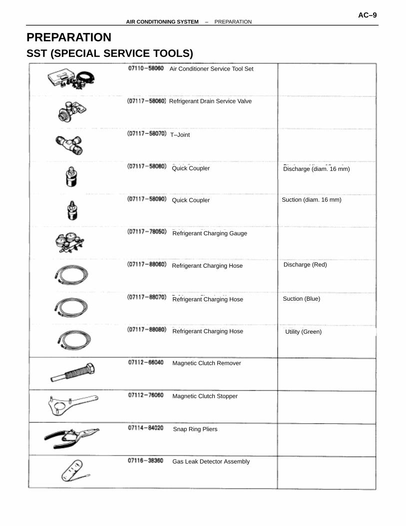
PREPARATIONSST (SPECIAL SERVICE TOOLS)
Air Conditioner Service Tool Set
Refrigerant Drain Service Valve
T–Joint
Quick Coupler
Quick Coupler
Refrigerant Charging Gauge
Refrigerant Charging Hose
Refrigerant Charging Hose
Refrigerant Charging Hose
Magnetic Clutch Remover
Magnetic Clutch Stopper
Snap Ring Pliers
Gas Leak Detector Assembly
Discharge (diam. 16 mm)
Suction (diam. 16 mm)
Suction (Blue)
Discharge (Red)
Utility (Green)
–AIR CONDITIONING SYSTEM PREPARATIONAC–9

RECOMMENDED TOOLS
TOYOTA Electrical Tester Set
LUBRICANTÑÑÑÑÑÑÑÑÑÑÑÑÑÑÑÑÑÑÑÑÑÑÑÑÑÑÑÑÑÑÑÑÑÑÑÑÑÑÑ
ItemÑÑÑÑÑÑÑÑÑÑÑÑÑÑÑÑÑÑÑÑÑÑÑÑÑÑÑÑÑÑÑÑÑÑÑÑ
CapacityÑÑÑÑÑÑÑÑÑÑÑÑÑÑÑÑÑÑÑÑÑÑÑÑÑÑÑÑÑÑÑÑÑÑÑÑÑÑÑ
Classification
ÑÑÑÑÑÑÑÑÑÑÑÑÑÑÑÑÑÑÑÑÑÑÑÑÑÑ
Compressor oil ÑÑÑÑÑÑÑÑÑÑÑÑÑÑÑÑÑÑÑÑÑÑÑÑ
– ÑÑÑÑÑÑÑÑÑÑÑÑÑÑÑÑÑÑÑÑÑÑÑÑÑÑ
ND–OIL 8 or equivalent
ÑÑÑÑÑÑÑÑÑÑÑÑÑÑÑÑÑÑÑÑÑÑÑÑÑÑ
When replacing receiver ÑÑÑÑÑÑÑÑÑÑÑÑÑÑÑÑÑÑÑÑÑÑÑÑ
10 cc (0.34 fl.oz.) ÑÑÑÑÑÑÑÑÑÑÑÑÑÑÑÑÑÑÑÑÑÑÑÑÑÑÑÑÑÑÑÑÑÑÑÑÑÑÑ
ÑÑÑÑÑÑÑÑÑÑÑÑÑ When replacing condenser ÑÑÑÑÑÑÑÑÑÑÑÑ
ÑÑÑÑÑÑÑÑÑÑÑÑ40 cc (1.4 fl.oz.) ÑÑÑÑÑÑÑÑÑÑÑÑÑ
ÑÑÑÑÑÑÑÑÑÑÑÑÑÑÑÑÑÑÑÑÑÑÑÑÑÑÑÑÑÑÑÑÑÑÑÑÑÑÑ
When replacing evaporator ÑÑÑÑÑÑÑÑÑÑÑÑÑÑÑÑÑÑÑÑÑÑÑÑ
40 cc (1.4 fl.oz.) ÑÑÑÑÑÑÑÑÑÑÑÑÑÑÑÑÑÑÑÑÑÑÑÑÑÑÑÑÑÑÑÑÑÑÑÑÑÑÑ
ÑÑÑÑÑÑÑÑÑÑÑÑÑ When replacing compressor
ÑÑÑÑÑÑÑÑÑÑÑÑÑÑÑÑÑÑÑÑÑÑÑÑ
140 cc (4.8 fl.oz.)ÑÑÑÑÑÑÑÑÑÑÑÑÑÑÑÑÑÑÑÑÑÑÑÑÑÑ
AC–10–AIR CONDITIONING SYSTEM PREPARATION
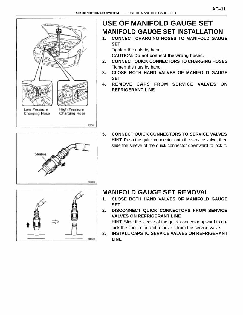
USE OF MANIFOLD GAUGE SETMANIFOLD GAUGE SET INSTALLATION1. CONNECT CHARGING HOSES TO MANIFOLD GAUGE
SETTighten the nuts by hand.CAUTION: Do not connect the wrong hoses.
2. CONNECT QUICK CONNECTORS TO CHARGING HOSESTighten the nuts by hand.
3. CLOSE BOTH HAND VALVES OF MANIFOLD GAUGESET
4. REMOVE CAPS FROM SERVICE VALVES ONREFRIGERANT LINE
5. CONNECT QUICK CONNECTORS TO SERVICE VALVESHINT: Push the quick connector onto the service valve, thenslide the sleeve of the quick connector downward to lock it.
MANIFOLD GAUGE SET REMOVAL1. CLOSE BOTH HAND VALVES OF MANIFOLD GAUGE
SET2. DISCONNECT QUICK CONNECTORS FROM SERVICE
VALVES ON REFRIGERANT LINEHINT: Slide the sleeve of the quick connector upward to un-lock the connector and remove it from the service valve.
3. INSTALL CAPS TO SERVICE VAL VES ON REFRIGERANTLINE
–AIR CONDITIONING SYSTEM USE OF MANIFOLD GAUGE SETAC–11

–MEMO–
AC–12–AIR CONDITIONING SYSTEM USE OF MANIFOLD GAUGE SET

TROUBLESHOOTING–AIR CONDITIONING SYSTEM TROUBLESHOOTING
AC–13

HOW TO PROCEED WITH TROUBLESHOOTINGPerform troubleshooting in accordance with the procedure on the following page.
P. AC–16
P. IN–24
P. AC–19
P. AC–19 P. AC–26
P. AC–28 ∼ AC–70
Vehicle Brought to Workshop
Customer Problem Analysis
Check and Clear Trouble Code (Precheck)
Problem Symptom Confirmation Symptom Simulation
Trouble Code Check
Trouble Code Chart Matrix Chart of Problem Symptoms
Circuit Inspection Actuator CheckPart Inspection
Identification of Problem
Repair
End
Confirmation Test
P. AC–19
Items inside are titles of pages in thismanual, with the page number indicated in the bottomportion. See the indicated pages for detailed explana-tions.
AC–14–AIR CONDITIONING SYSTEM TROUBLESHOOTING

CUSTOMER PROBLEM ANALYSIS CHECK SHEETÑÑÑÑÑÑÑÑÑÑÑÑÑÑÑÑÑÑÑÑÑÑÑÑÑÑÑÑÑÑÑÑÑÑÑÑÑÑÑÑÑÑÑÑÑÑÑÑÑÑ
AIR CONDITIONING SYSTEM Check Sheet
–AIR CONDITIONING SYSTEM TROUBLESHOOTINGAC–15
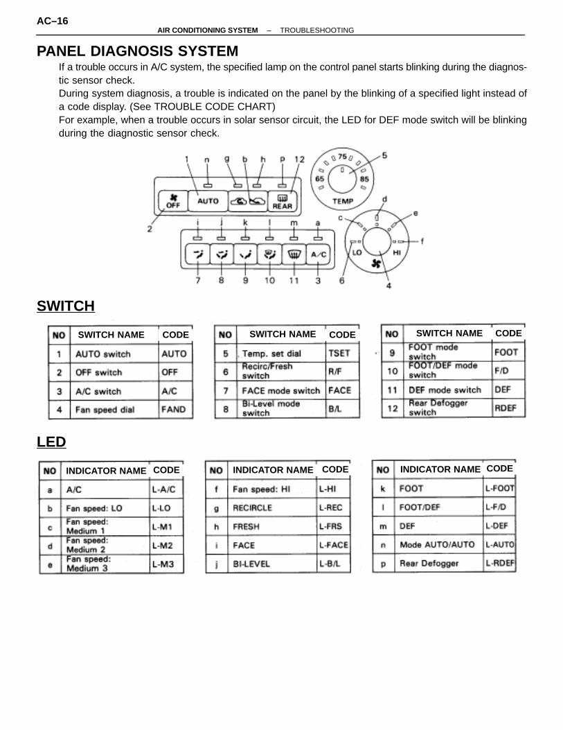
PANEL DIAGNOSIS SYSTEMIf a trouble occurs in A/C system, the specified lamp on the control panel starts blinking during the diagnos-tic sensor check.During system diagnosis, a trouble is indicated on the panel by the blinking of a specified light instead ofa code display. (See TROUBLE CODE CHART)For example, when a trouble occurs in solar sensor circuit, the LED for DEF mode switch will be blinkingduring the diagnostic sensor check.
SWITCH
SWITCH NAME CODE CODE SWITCH NAME CODESWITCH NAME
LED
INDICATOR NAME CODE INDICATOR NAME CODE INDICATOR NAME CODE
AC–16–AIR CONDITIONING SYSTEM TROUBLESHOOTING
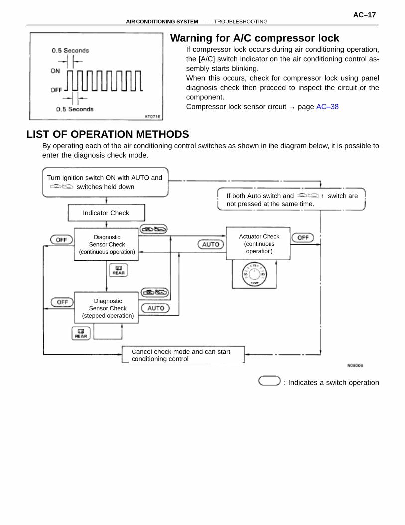
Warning for A/C compressor lockIf compressor lock occurs during air conditioning operation,the [A/C] switch indicator on the air conditioning control as-sembly starts blinking.When this occurs, check for compressor lock using paneldiagnosis check then proceed to inspect the circuit or thecomponent.Compressor lock sensor circuit → page AC–38
LIST OF OPERATION METHODSBy operating each of the air conditioning control switches as shown in the diagram below, it is possible toenter the diagnosis check mode.
Indicator Check
DiagnosticSensor Check
(continuous operation)
DiagnosticSensor Check
(stepped operation)
Cancel check mode and can startconditioning control
Actuator Check(continuousoperation)
Turn ignition switch ON with AUTO andswitches held down.
If both Auto switch and switch arenot pressed at the same time.
: Indicates a switch operation
–AIR CONDITIONING SYSTEM TROUBLESHOOTINGAC–17

INDICATOR CHECK1. Turn the ignition switch on while pressing the air conditioning
control AUTO switch and R/F SW simultaneously.
2. Check that all the indicators light up and go off at 1second intervals 4 times in succession.HINT:• After the indicator check is ended, the diagnostic sensor
check begins automatically.• Press the OFF switch when cancelling the check mode.
DIAGNOSTIC SENSOR CHECK1. Perform an indicator check. After the indicator check is
completed, the system enters the diagnostic sensor checkmode automatically.
2. Check the LED blinking on the panel. Refer to the list of codeson page AC–20 when translating the trouble code from theLED blinking.If the slower display is desired, press the RDEF switch andchange it to step operation. Each time the RDEF switch ispressed, the blinking LED changes by 1 step.
CLEARING TROUBLE CODES’ MEMORYMethod 1:
1. Pull out the ECU–B fuse in Junction Block No. 1 for 10 sec.or longer to clear the trouble codes’ memory.
2. After reinserting the fuse, check that the normal code isoutput.
Method 2:Press the RDEF switch while pushing the A/C switch duringthe sensor check mode.
AC–18–AIR CONDITIONING SYSTEM TROUBLESHOOTING

–MEMO–
–AIR CONDITIONING SYSTEM TROUBLESHOOTINGAC–19
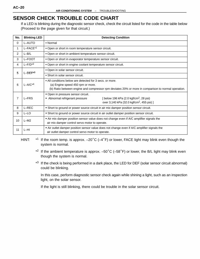
SENSOR CHECK TROUBLE CODE CHARTIf a LED is blinking during the diagnostic sensor check, check the circuit listed for the code in the table below(Proceed to the page given for that circuit.)
ÑÑÑÑÑÑÑÑÑ
No.ÑÑÑÑÑÑÑÑÑÑÑÑÑÑÑ
Blinking LEDÑÑÑÑÑÑÑÑÑÑÑÑÑÑÑÑÑÑÑÑÑÑÑÑÑÑÑÑÑÑÑÑÑÑÑÑÑÑÑÑÑÑÑÑÑÑÑÑÑÑÑÑÑÑÑÑÑÑÑÑÑÑÑÑÑÑÑÑÑÑÑÑÑÑÑÑÑÑÑÑÑÑÑÑÑÑÑÑÑÑ
Detecting Condition
ÑÑÑÑÑÑ
0 ÑÑÑÑÑÑÑÑÑÑ
L–AUTO ÑÑÑÑÑÑÑÑÑÑÑÑÑÑÑÑÑÑÑÑÑÑÑÑÑÑÑÑÑÑÑÑÑÑÑÑÑÑÑÑÑÑÑÑÑÑÑÑÑÑÑÑÑÑÑÑÑÑÑÑ
� Normal
ÑÑÑÑÑÑ
1 ÑÑÑÑÑÑÑÑÑÑ
L–FACE*1 ÑÑÑÑÑÑÑÑÑÑÑÑÑÑÑÑÑÑÑÑÑÑÑÑÑÑÑÑÑÑÑÑÑÑÑÑÑÑÑÑÑÑÑÑÑÑÑÑÑÑÑÑÑÑÑÑÑÑÑÑ
� Open or short in room temperature sensor circuit.
ÑÑÑÑÑÑ
2 ÑÑÑÑÑÑÑÑÑÑ
L–B/L ÑÑÑÑÑÑÑÑÑÑÑÑÑÑÑÑÑÑÑÑÑÑÑÑÑÑÑÑÑÑÑÑÑÑÑÑÑÑÑÑÑÑÑÑÑÑÑÑÑÑÑÑÑÑÑÑÑÑÑÑ
� Open or short in ambient temperature sensor circuit.
ÑÑÑÑÑÑ
3 ÑÑÑÑÑÑÑÑÑÑ
L–FOOT ÑÑÑÑÑÑÑÑÑÑÑÑÑÑÑÑÑÑÑÑÑÑÑÑÑÑÑÑÑÑÑÑÑÑÑÑÑÑÑÑÑÑÑÑÑÑÑÑÑÑÑÑÑÑÑÑÑÑÑÑ
� Open or short in evaporator temperature sensor circuit.
ÑÑÑÑÑÑ
4 ÑÑÑÑÑÑÑÑÑÑ
L–F/D*2 ÑÑÑÑÑÑÑÑÑÑÑÑÑÑÑÑÑÑÑÑÑÑÑÑÑÑÑÑÑÑÑÑÑÑÑÑÑÑÑÑÑÑÑÑÑÑÑÑÑÑÑÑÑÑÑÑÑÑÑÑ
� Open or short in engine coolant temperature sensor circuit.
ÑÑÑÑÑÑ5ÑÑÑÑÑÑÑÑÑÑL DEF*3
ÑÑÑÑÑÑÑÑÑÑÑÑÑÑÑÑÑÑÑÑÑÑÑÑÑÑÑÑÑÑÑÑÑÑÑÑÑÑÑÑÑÑÑÑÑÑÑÑÑÑÑÑÑÑÑÑÑÑÑÑ
� Open in solar sensor circuit.
ÑÑÑÑÑÑ
5 ÑÑÑÑÑÑÑÑÑÑ
L–DEF*3 ÑÑÑÑÑÑÑÑÑÑÑÑÑÑÑÑÑÑÑÑÑÑÑÑÑÑÑÑÑÑÑÑÑÑÑÑÑÑÑÑÑÑÑÑÑÑÑÑÑÑÑÑÑÑÑÑÑÑÑÑ
� Short in solar sensor circuit.ÑÑÑÑÑÑÑÑÑÑÑÑ
6
ÑÑÑÑÑÑÑÑÑÑÑÑÑÑÑÑÑÑÑÑ
L–A/C*4
ÑÑÑÑÑÑÑÑÑÑÑÑÑÑÑÑÑÑÑÑÑÑÑÑÑÑÑÑÑÑÑÑÑÑÑÑÑÑÑÑÑÑÑÑÑÑÑÑÑÑÑÑÑÑÑÑÑÑÑÑÑÑÑÑÑÑÑÑÑÑÑÑÑÑÑÑÑÑÑÑÑÑÑÑÑÑÑÑÑÑÑÑÑÑÑÑÑÑÑÑÑÑÑÑÑÑÑÑÑÑÑÑÑÑÑÑÑÑÑÑ
� All conditions below are detected for 3 secs. or more. (a) Engine speed 450 rpm or more. (b) Ratio between engine and compressor rpm deviates 20% or more in comparison to normal operation.
ÑÑÑÑÑÑÑÑÑ
7ÑÑÑÑÑÑÑÑÑÑÑÑÑÑÑ
L–FRSÑÑÑÑÑÑÑÑÑÑÑÑÑÑÑÑÑÑÑÑÑÑÑÑÑÑÑÑÑÑÑÑÑÑÑÑÑÑÑÑÑÑÑÑÑÑÑÑÑÑÑÑÑÑÑÑÑÑÑÑÑÑÑÑÑÑÑÑÑÑÑÑÑÑÑÑÑÑÑÑÑÑÑÑÑÑÑÑÑÑ
� Open in pressure sensor circuit.� Abnormal refrigerant pressure [ below 196 kPa (2.0 kgf/cm2, 28 psi) over 3,140 kPa (32.0 kgf/cm2, 455 psi) ]ÑÑÑ
ÑÑÑÑÑÑ
8ÑÑÑÑÑÑÑÑÑÑÑÑÑÑÑ
L–RECÑÑÑÑÑÑÑÑÑÑÑÑÑÑÑÑÑÑÑÑÑÑÑÑÑÑÑÑÑÑÑÑÑÑÑÑÑÑÑÑÑÑÑÑÑÑÑÑÑÑÑÑÑÑÑÑÑÑÑÑÑÑÑÑÑÑÑÑÑÑÑÑÑÑÑÑÑÑÑÑÑÑÑÑÑÑÑÑÑÑ
� Short to ground or power source circuit in air mix damper position sensor circuit.
ÑÑÑÑÑÑ
9 ÑÑÑÑÑÑÑÑÑÑ
L–LO ÑÑÑÑÑÑÑÑÑÑÑÑÑÑÑÑÑÑÑÑÑÑÑÑÑÑÑÑÑÑÑÑÑÑÑÑÑÑÑÑÑÑÑÑÑÑÑÑÑÑÑÑÑÑÑÑÑÑÑÑ
� Short to ground or power source circuit in air outlet damper position sensor circuit.
ÑÑÑÑÑÑ
10ÑÑÑÑÑÑÑÑÑÑ
L–M2 ÑÑÑÑÑÑÑÑÑÑÑÑÑÑÑÑÑÑÑÑÑÑÑÑÑÑÑÑÑÑÑÑÑÑÑÑÑÑÑÑÑÑÑÑÑÑÑÑÑÑÑÑÑÑÑÑÑÑÑÑ
� Air mix damper position sensor value does not change even if A/C amplifier signals the air mix damper control servo motor to operate.ÑÑÑ
ÑÑÑÑÑÑ
11
ÑÑÑÑÑÑÑÑÑÑÑÑÑÑÑ
L–HI
ÑÑÑÑÑÑÑÑÑÑÑÑÑÑÑÑÑÑÑÑÑÑÑÑÑÑÑÑÑÑÑÑÑÑÑÑÑÑÑÑÑÑÑÑÑÑÑÑÑÑÑÑÑÑÑÑÑÑÑÑÑÑÑÑÑÑÑÑÑÑÑÑÑÑÑÑÑÑÑÑÑÑÑÑÑÑÑÑÑÑ
� Air outlet damper position sensor value does not change even if A/C amplifier signals the air outlet damper control servo motor to operate.
HINT: *1 If the room temp. is approx. –20°C (–4°F) or lower, FACE light may blink even though thesystem is normal.
*2 If the ambient temperature is approx. –50°C (–58°F) or lower, the B/L light may blink eventhough the system is normal.
*3 If the check is being performed in a dark place, the LED for DEF (solar sensor circuit abnormal)could be blinking.
In this case, perform diagnostic sensor check again while shining a light, such as an inspectionlight, on the solar sensor.
If the light is still blinking, there could be trouble in the solar sensor circuit.
AC–20–AIR CONDITIONING SYSTEM TROUBLESHOOTING

AC–28
AC–30
AC–32
AC–34
AC–36
AC–38
AC–40
AC–42
AC–48
AC–42AC–44
AC–48AC–50
Trouble Area Memory* 5 See page
(8.5 min. or more)
(8.5 min. or more)
(8.5 min. or more)
(8.5 min. or more)
(8.5 min. or more)
(1 min. or more)
(1 min. or more)
(15 secs. or more)
(15 secs. or more)
� Room temp. sensor� Harness or connector between room temp. sensor and A/C amplifier� A/C amplifier
� Ambient temp. sensor� Harness or connector between ambient temp. sensor and A/C amplifier� A/C amplifier� Evaporator temp. sensor� Harness or connector between evaporator temp. sensor and A/C amplifier� A/C amplifier
� Engine coolant temp. sensor� Harness or connector between coolant temp. sensor and A/C amplifier� A/C amplifier
� Solar sensor� Harness or connector between sensor and A/C amplifier� A/C amplifier
� Compressor drive belt � Compressor lock sensor � Compressor� Harness and connector between A/C amplifier and compressor, compressor
lock sensor� A/C amplifier
� Pressure switch� Harness or connector between pressure switch and A/C amplifier� Refrigerant pipe line� A/C amplifier
� Air mix damper position sensor � A/C amplifier� Harness or connector between air mix damper position sensor and A/C amplifier
� Air outlet damper position sensor � A/C amplifier� Harness or connector between max cool damper position sensor and A/C amplifi-er� Air mix damper control servo motor � Air mix damper position sensor� Harness and connector between A/C amplifier and air mix position sensor� Harness and connector between A/C amplifier and air mix damper control
servo motor � A/C amplifier
� Air outlet damper control servo motor � Air outlet damper position sensor� Harness and connector between A/C amplifier and air outlet position sensor� Harness and connector between A/C amplifier and air outlet damper motor� A/C amplifier
HINT: *4 Compressor lock (A/C light blink) is indicated only for a current malfunction. (See page AC–38)
To confirm the trouble indication, perform the following steps.(1) With the engine ON, enter the trouble code check mode.(2) Press the R/F switch to enter actuator check mode, and set the operation to Step No. 3.(3) Press the AUTO switch to return to diagnostic sensor check mode.(4) The A/C light starts to blink after approx. 3 secs.
*5 The A/C amplifier memorizes the trouble code of the respective malfunction when it occursfor period of time indicated in the brackets.
–AIR CONDITIONING SYSTEM TROUBLESHOOTINGAC–21
Step No.
Conditions
Blower Motor
Air Flow vent
Air Inlet damper
Set Temperature
°C (°F) Magneticclutch
Air mix damper
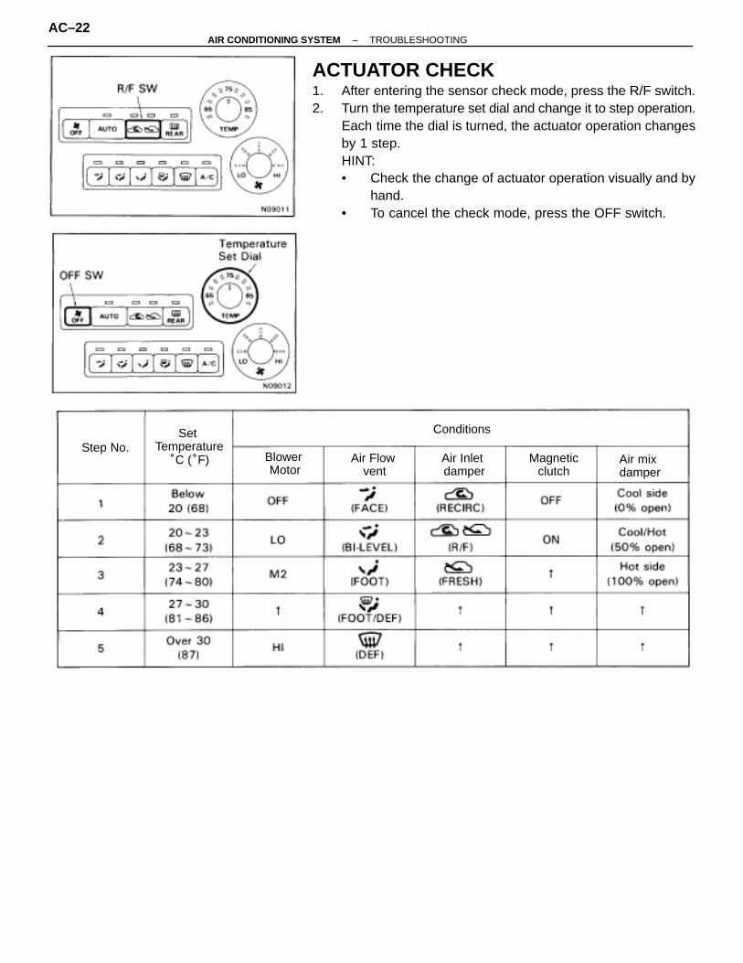
ACTUATOR CHECK1. After entering the sensor check mode, press the R/F switch.2. Turn the temperature set dial and change it to step operation.
Each time the dial is turned, the actuator operation changesby 1 step.HINT:• Check the change of actuator operation visually and by
hand.• To cancel the check mode, press the OFF switch.
AC–22–AIR CONDITIONING SYSTEM TROUBLESHOOTING

Condition Standard ValueSymbolTerminal
No.Tester
ConnectionWiringColor
A C AMPLIFIER TERMINAL STANDARD VALUE
–AIR CONDITIONING SYSTEM TROUBLESHOOTINGAC–23

TerminalNo. Symbol
TesterConnection
WiringColor Condition Standard Value
* After 15 minutes, ON mode will change to OFF mode automatically.
AC–24–AIR CONDITIONING SYSTEM TROUBLESHOOTING

–MEMO–
–AIR CONDITIONING SYSTEM TROUBLESHOOTINGAC–25
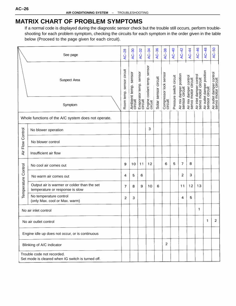
MATRIX CHART OF PROBLEM SYMPTOMSIf a normal code is displayed during the diagnostic sensor check but the trouble still occurs, perform trouble-shooting for each problem symptom, checking the circuits for each symptom in the order given in the tablebelow (Proceed to the page given for each circuit).
AC
–28
AC
–30
AC
–32
AC
–34
AC
–36
AC
–38
AC
–40
AC
–42
AC
–44
AC
–46
AC
–48
AC
–50
See page
Suspect Area
Symptom
Whole functions of the A/C system does not operate.
No blower operation
No blower control
Insufficient air flow
No cool air comes out
No warm air comes out
Output air is warmer or colder than the settemperature or response is slow
No temperature control(only Max. cool or Max. warm)
No air inlet control
No air outlet control
Engine idle up does not occur, or is continuous
Blinking of A/C indicator
Trouble code not recorded.Set mode is cleared when IG switch is turned off.
Tem
pera
ture
Con
trol
Air
Flo
w C
ontr
ol
Roo
m te
mp.
sen
sor
circ
uit
Am
bien
t tem
p. s
enso
rci
rcui
tE
vapo
rato
r te
mp.
sen
sor
circ
uit
Sol
ar s
enso
r ci
rcui
t
Eng
ine
cool
ant t
emp.
sen
sor
circ
uit
Pre
ssur
e sw
itch
circ
uit
Air
mix
dam
per
posi
tion
sens
or c
ircui
tA
ir m
ix d
ampe
r co
ntro
lse
rvo
mot
or c
ircui
tA
ir in
let d
ampe
r co
ntro
lse
rvo
mot
or c
ircui
t
Air
outle
t dam
per
cont
rol
serv
o m
otor
circ
uit
Com
pres
sor
lock
sen
sor
circ
uit
Air
outle
t dam
per
posi
tion
sens
or c
ircui
t
AC–26–AIR CONDITIONING SYSTEM TROUBLESHOOTING
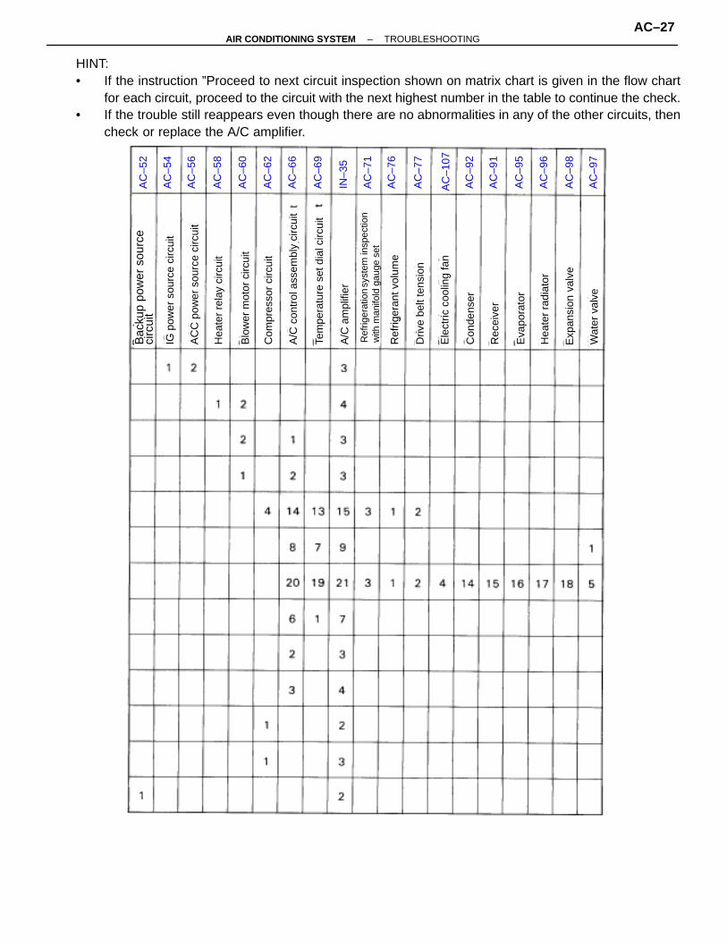
HINT:• If the instruction ”Proceed to next circuit inspection shown on matrix chart is given in the flow chart
for each circuit, proceed to the circuit with the next highest number in the table to continue the check.• If the trouble still reappears even though there are no abnormalities in any of the other circuits, then
check or replace the A/C amplifier.A
C–5
2
AC
–54
AC
–56
AC
–58
AC
–60
AC
–62
AC
–66
AC
–69
IN–3
5
AC
–71
AC
–76
AC
–77
AC
–107
AC
–92
AC
–91
AC
–95
AC
–96
AC
–98
AC
–97
IG p
ower
sou
rce
circ
uit
Bac
kup
pow
er s
ourc
eci
rcui
t
AC
C p
ower
sou
rce
circ
uit
Hea
ter
rela
y ci
rcui
t
Com
pres
sor
circ
uit
Blo
wer
mot
or c
ircui
t
A/C
am
plifi
er
Tem
pera
ture
set
dia
l circ
uit
A/C
con
trol
ass
embl
y ci
rcui
t
Ref
riger
atio
n sy
stem
insp
ectio
nw
ith m
anifo
ld g
auge
set
Ele
ctric
coo
ling
fan
Wat
er v
alve
Driv
e be
lt te
nsio
n
Ref
riger
ant v
olum
e
Con
dens
er
Exp
ansi
on v
alve
Eva
pora
tor
Hea
ter
radi
ator
Rec
eive
r
–AIR CONDITIONING SYSTEM TROUBLESHOOTINGAC–27

CIRCUIT INSPECTION
Blinking Light FACE Room Temperature Sensor Circuit
CIRCUIT DESCRIPTION
This sensor detects the temperature inside the cabin and sends the appropriate signals to the A/C am-plifier.
Diagnostic Sensor Check Detecting Condition
Open or short in room temperature sensor circuit.
Trouble Area
� Room temperature sensor� Harness or connector between room temperature sensor and A/C amplifier� A/C amplifier
AC–28–AIR CONDITIONING SYSTEM TROUBLESHOOTING

INSPECTION PROCEDURE
Proceed to next circuit inspection shown on matrixchart (See page AC–26). However, if the light is stillblinking, check and replace A/C amplifier.
(See page IN–30).(See Page IN–30).
Remove A/C amplifier with connectors still con-nected.
Check voltage between terminals TR and SG of A/C amplifier connector.
Check room temperature sensor.
Check harness and connector between A/C amplifier and roomtemperature sensor (See page IN–30).
Replace room temperature sensor.
Repair or replace harness or connector.
Check and replace A/C amplifier.
1. Turn ignition switch ON.2. Measure voltage between terminal TR of SG
of A/C amplifier connector at each temperature.
1. Remove instrument panel.2. Disconnect room temperature sensor connector.
Check resistance between terminals 1 and 2 of roomtemperature sensor connector. Resistance:
at 25°C (77°F): 1.6 ∼ 1.8 k�
HINT: As the temperature increases, the voltage decreases gradually.
Voltage: at 25°C (77°F): 1.8 ∼ 2.2 Vat 40°C (104°F): 1.2 ∼ 1.6 V
–AIR CONDITIONING SYSTEM TROUBLESHOOTINGAC–29

CIRCUIT DESCRIPTION
This sensor detects the ambient temperature and sends the appropriate signals to the A/C amplifier.
Diagnostic Sensor Check Detecting Condition
Open or short in ambient temperature sensor circuit.
Trouble Area
� Ambient temperature sensor� Harness or connector between ambient tempera–
ture sensor and A/C amplifier� A/C amplifier
Blinking Light B L Ambient Temperature Sensor Circuit
AC–30–AIR CONDITIONING SYSTEM TROUBLESHOOTING

(See page AC–26)
(See page IN–30).
Check voltage between terminals TAM and SG of A/C amplifier connector.
Check ambient temperature sensor.
Check harness and connector between A/C amplifier and ambienttemperature sensor (See page IN–30).
Proceed to next circuit inspection shown on matrixchart (See page AC–26). However, if the light is stillblinking, check and replace A/C amplifier.
Check and replace A/C amplifier.
Repair or replace harness or connector.
Replace ambient temperature sensor.
Remove A/C amplifier with connectors still con-nected.
1. Turn ignition switch ON.2. Measure voltage between terminal TAM of SG
of A/C amplifier connector at each temperature.
HINT: As the temperature increases, the voltage decreases gradually.
Voltage:at 25°C (77°F): 1.35 ∼ 1.75 Vat 40°C (104°F): 0.85 ∼ 1.25 V
1. Remove the clip and the sensor from the rightside inside the bumper reinforcement.
2. Disconnect ambient temperature sensor connec–tor.
Check resistance between terminals 1 and 2 of ambi-ent temperature sensor connector at each tempera-ture. Resistance:
at 25°C (77°F): 1.6 ∼ 1.8 k�at 50°C (122°F): 0.5 ∼ 0.7 k�
HINT: As the temperature increases, the resistancedecreases gradually.
NOTICE:When installing the ambient temperature sensor, be sure to connect the sensor connector before connecting the battery.
INSPECTION PROCEDURE
–AIR CONDITIONING SYSTEM TROUBLESHOOTINGAC–31

Blinking Light FOOT Evaporator Temperature Sensor Circuit
CIRCUIT DESCRIPTION
This sensor detects the temperature inside the cooling unit and sends the appropriate signals to theA/C amplifier.
Diagnostic Sensor Check Detecting Condition Trouble Area
Open or short in evaporator temperature sensor circuit.
� Evaporator temperature sensor� Harness or connector between evaporator temperature sensor and A/C amplifier� A/C amplifier
AC–32–AIR CONDITIONING SYSTEM TROUBLESHOOTING

INSPECTION PROCEDURE
(See page AC–26).
(See page IN–30)
Check voltage between terminals TE and SG of A/C amplifier connector.
Check and replace A/C amplifier.
Repair or replace harness or connector.
Replace evaporator temperature sensor.
Check harness and connector between A/C amplifier and evaporatortemperature sensor (See page IN–30).
Proceed to next circuit inspection shown on matrixchart (See page AC–26). However, if the light is stillblinking, check and replace A/C amplifier.
Check evaporator temperature sensor.
Remove A/C amplifier with connectors still con-nected.
1. Turn ignition switch ON.2. Measure voltage between terminal TE of SG
of A/C amplifier connector at each temperature.
HINT: As the temperature increases, the voltage decreases gradually.
Voltage: at 0°C (32°F): 2.0 ∼ 2.4 Vat 15°C (59°F): 1.4 ∼ 1.8 V
Check resistance between terminals 1 and 2 of evapo-rator temperature sensor connector at each tempera-ture. Resistance:
at 0°C (32°F): 4.5 ∼ 5.2 k�at 15°C (59°F): 2.0 ∼ 2.7 k�
HINT: As the temperature increases, the resistancedecreases gradually.
Remove evaporator temperature sensor (See pageAC–106)
–AIR CONDITIONING SYSTEM TROUBLESHOOTINGAC–33

Blinking Light F D Engine Coolant Temperature Sensor Circuit
CIRCUIT DESCRIPTION
This sensor detects the coolant temperature and sends the appropriate signals to the A/C amplifier.These signals are used for warm up control when the engine is cold.
Diagnostic Sensor Check Detecting Condition Trouble Area
Open or short in engine coolant temperature sensorcircuit.
� Engine coolant temperature sensor� Harness or connector between engine coolant
temperature sensor and A/C amplifier� A/C amplifier
AC–34–AIR CONDITIONING SYSTEM TROUBLESHOOTING

INSPECTION PROCEDURE
(See page AC–26).
(See page IN–30)
Check voltage between terminals TW and SG of A/C amplifier connector.
Proceed to next circuit inspection shown on matrixchart (See page AC–26). However, if the light is stillblinking, check and replace A/C amplifier.
Check engine coolant temperature sensor.
Replace engine coolant temperature sensor.
Check harness and connector between A/C amplifier and engine coolanttemperature sensor (See page IN–30).
Repair or replace harness or connector.
Check and replace A/C amplifier.
Remove A/C amplifier with connectors still con-nected.
1. Turn ignition switch ON.2. Measure voltage between terminal TW of SG
of A/C amplifier connector at each temperature.
HINT: As the temperature increases, the voltage decreases gradually.
Voltage: at 0°C (32°F): 2.8 ∼ 3.2 Vat 40°C (104°F): 1.8 ∼ 2.2 Vat 70°C (158°F): 1.3 ∼ 1.5 V
1. Remove A/C unit (See page AC–80).2. Remove engine coolant temperature sensor.
Measure resistance between terminals 1 and 2 of en-gine coolant temperature sensor connector at eachtemperature.
HINT: As the temperature increases, the resistance decreases gradually.
Resistance: at 0°C (32°F): Below 50 k �
at 40°C (104°F): 2.4 ∼ 2.8 k�at 100°C (212°F): Over 0.2 k�
–AIR CONDITIONING SYSTEM TROUBLESHOOTINGAC–35

Blinking Light DEF Solar Sensor Circuit
CIRCUIT DESCRIPTION
A photo diode in the solar sensor detects solar radi–ation and sends signals to the A/C amplifier.
Diagnostic Sensor Check Detecting Condition Trouble Area
� Solar sensor� Harness or connector between solar sensor and
A/C amplifier� A/C amplifier
Open or short in solar sensor circuit.Please not that blinking of the LED for DEF is notabnormal when the sensor is not receiving solarradiation.
AC–36–AIR CONDITIONING SYSTEM TROUBLESHOOTING
(See page IN–30)
Check and replace A/C amplifier.
Repair or replace harness or connector.
Check harness and connector between A/C amplifier and solar sensor(See page IN–30).
Replace solar sensor.
Check solar sensor.
Proceed to next circuit inspection shown on matrixchart (See page AC–26). However, if the light is stillblinking, check and replace A/C amplifier.
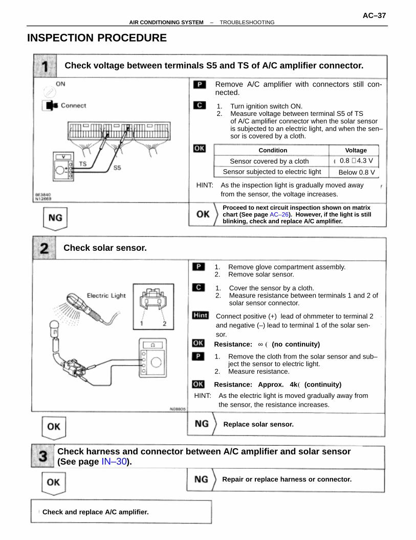
Check voltage between terminals S5 and TS of A/C amplifier connector.
1. Turn ignition switch ON.2. Measure voltage between terminal S5 of TS
of A/C amplifier connector when the solar sensor is subjected to an electric light, and when the sen–sor is covered by a cloth.
HINT: As the inspection light is gradually moved away from the sensor, the voltage increases.
HINT: As the electric light is moved gradually away from the sensor, the resistance increases.
1. Remove glove compartment assembly.2. Remove solar sensor.
1. Cover the sensor by a cloth.2. Measure resistance between terminals 1 and 2 of
solar sensor connector.
1. Remove the cloth from the solar sensor and sub–ject the sensor to electric light.
2. Measure resistance.
Remove A/C amplifier with connectors still con-nected.
Condition Voltage
Sensor covered by a cloth
Sensor subjected to electric light
0.8 ∼ 4.3 V
Below 0.8 V
Connect positive (+) lead of ohmmeter to terminal 2and negative (–) lead to terminal 1 of the solar sen-sor.Resistance: ∞ � (no continuity)
Resistance: Approx. 4k � (continuity)
INSPECTION PROCEDURE
–AIR CONDITIONING SYSTEM TROUBLESHOOTINGAC–37

Blinking Light A C Compressor Lock Sensor Circuit
CIRCUIT DESCRIPTION
This sensor sends 1 pulse per engine revolution to the A/C amplifier. If the number ratio of the compres-sor speed divided by the engine speed is smaller than a predetermined value, the A/C amplifier turnsthe compressor off. And, the indicator flashes at about 1 second intervals.
Diagnostic Sensor Check Detecting Condition Trouble Area
� Compressor � Compressor drive belt� Compressor lock sensor� Harness and connector between compressor and
A/C amplifier� A/C amplifier
All conditions below are detected for 3 secs. or more(a) Engine speed: 450 rpm or more (b) Ratio between engine and compressor speed
deviates 20% or more in comparison to normal operation.
AC–38–AIR CONDITIONING SYSTEM TROUBLESHOOTING

INSPECTION PROCEDURE
(See page AC–26).
(See page IN–30).
Repair or replace harness or connector.
Replace compressor lock sensor.
Check for open and short harness and connector between A/C amplifierand room temperature sensor (See page IN–30).
Check compressor lock sensor.
Check compressor.
Adjust drive belt tension or repair compressor.
Proceed to next circuit inspection shown on matrixchart (See page AC–26). However, if the light is stillblinking, check and replace A/C amplifier.
Disconnect compressor lock sensor connector
Measure resistance between terminals 1 and 2 ofcompressor lock sensor connector.
Resistance: at 20 °C (68°F): 160 ∼ 210 �
(1) Check compressor drive belt tension.(2) Check the compressor does not lock during operation with engine started and blowerswitch and A/C switch ON.
–AIR CONDITIONING SYSTEM TROUBLESHOOTINGAC–39

Blinking Light FRS Pressure Switch Circuit
CIRCUIT DESCRIPTION
The pressure switch sends the appropriate signals to the A/C amplifier when the air conditioning refrig-erant pressure drops too low or rises too high. When the A/C amplifier receives these signals, it outputssignals via the ECM to switch OFF the compressor relay and turns the magnetic clutch OFF.
Diagnostic Sensor Check Detecting Condition Trouble Area
� Pressure switch� Harness or connector between pressure switch
and A/C amplifier� Refrigerant pipe line� A/C amplifier
Open in pressure sensor circuitAbnormal refrigerant pressure
below 196 kPa (2.0 kgf/cm2, 28 psi)over 3,140 kPa (32.0 kgf/cm2, 455 psi)
AC–40–AIR CONDITIONING SYSTEM TROUBLESHOOTING

Check voltage between terminal PSW of A/C amplifier and body ground.
Check pressure switch.
Repair or replace harness or connector.
Check and replace A/C amplifier.
Repair or replace harness or connector.
Check harness and connector between A/C amplifier and roomtemperature sensor (See page IN–30).
Proceed to next circuit inspection shown on matrixchart (See page AC–26).
Install the manifold gauge set.
The voltage changes with gas pressure, as shownin the diagram below.
1. Turn ignition switch ON.2. Check voltage between terminal PSW of A/C
amplifier connector and body ground when airconditioning gas pressure is changed.
Disconnect pressure switch connector.
1. Turn ignition switch ON.2. Check continuity between terminals 1 and 4 (2
and 1) of pressure switch when air conditioninggas pressure is changed.
The continuity changes with gas pressure asshown below
Low Pressure Cut Side
Low Pressure Cut SideReference:High Pressure Cut Side
Reference:High Pressure Cut Side
INSPECTION PROCEDURE
–AIR CONDITIONING SYSTEM TROUBLESHOOTINGAC–41
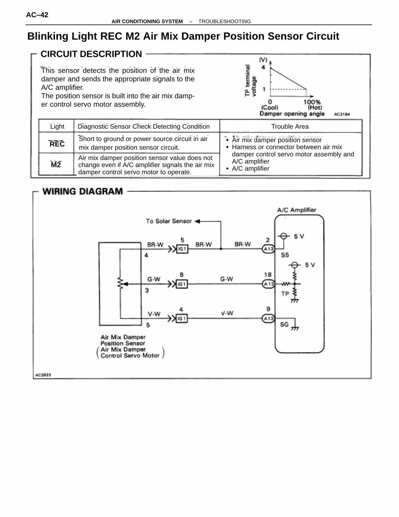
Blinking Light REC M2 Air Mix Damper Position Sensor Circuit
CIRCUIT DESCRIPTION
This sensor detects the position of the air mixdamper and sends the appropriate signals to theA/C amplifier.The position sensor is built into the air mix damp-er control servo motor assembly.
Diagnostic Sensor Check Detecting Condition Trouble Area
� Air mix damper position sensor� Harness or connector between air mix
damper control servo motor assembly andA/C amplifier
� A/C amplifier
Light
REC
M2
Short to ground or power source circuit in airmix damper position sensor circuit.
Air mix damper position sensor value does notchange even if A/C amplifier signals the air mixdamper control servo motor to operate.
AC–42–AIR CONDITIONING SYSTEM TROUBLESHOOTING

(See page IN–30).
Check voltage between terminals TP and SG of A/C amplifier connector.
Check air mix damper position sensor.
Check and replace A/C amplifier.
Check harness and connector between A/C amplifier and air mixdamper control servo motor assembly (See page IN–30).
Repair or replace harness or connector.
Replace air mix damper control servo motor as-sembly.
Proceed to next circuit inspection shown on matrixchart (See page AC–26). However, if the light is stillblinking, check and replace A/C amplifier.
Set Temperature Voltage
Position Resistance
Remove A/C amplifier with connectors still connected.
1. Turn ignition switch ON.2. Change the set temperature to activate the air mix
damper control servo motor, and measure the voltage between terminals TP and SG of A/C amplifier connector each time when the set temperature is changed.
HINT: As the set temperature increases, the voltage decreases.
1. Remove instrument panel.2. Disconnect air mix damper control servo motor as
sembly connector.
Measure resistance between terminals 4 and 5 of airmix damper control servo motor assembly connector.
While operating air mix damper control servo motor,following the procedure on page AC–44, measure re-sistance between terminals 5 and 3 of air mix dampercontrol servo motor assembly connector.
HINT: As the air mix damper control servo motor moves from cool side to hot side, the resistance decreases.
Resistance: 4.8 ∼ 7.2 k�
INSPECTION PROCEDURE
–AIR CONDITIONING SYSTEM TROUBLESHOOTINGAC–43

Blinking Light M2 Air Mix Damper Control Servo Motor Circuit
CIRCUIT DESCRIPTION
The air mix damper control servo motor is controlled by the A/C amplifier and signals the air mix damperto move to the desired position.
Diagnostic Sensor Check Detecting Condition Trouble Area
Air mix damper position sensor value does not change even if A/C amplifier signals the air mix damper control servo motor to operate.
� Air mix damper control servo motor� Air mix damper position sensor� Harness or connector between A/C amplifier and
A/M damper control servo motor, A/M damperposition sensor
� A/C amplifier
AC–44–AIR CONDITIONING SYSTEM TROUBLESHOOTING

(See page IN–30).
AC–22).
Actuator check.
Check and replace A/C amplifier.
Check harness and connector between A/C amplifier and air mix damper control ser-vo motor assembly (See page IN–30).
Repair or replace harness or connector.
Replace air mix damper control servo motorassembly.
Check air mix damper control servo motor.
Proceed to next circuit inspection shown on matrixchart (See page AC–26).
Remove air mix damper control servo motor assem-bly
The lever turns smoothly to Cool side.
The lever turns smoothly to Hot side.
Turn the TSET dial and check the operation of the airmix damper and the condition of the blower.
Set Temp. Air Mix Damper Condition
Connect negative (–) lead to terminal 2 and positive(+) lead to terminal 1.
Connect positive (+) lead to terminal 2 and negative(–) lead to terminal 1.
1. Warm up the engine.2. Set to the actuator check mode (See page AC–22)3. Turn the TSET dial and change it to step operation.
Cool air comes out
Warm air comes out
0% (Fully closed)
100% (Fully opened)
Below 20
Over 23
20 ∼ 23 50%
INSPECTION PROCEDURE
–AIR CONDITIONING SYSTEM TROUBLESHOOTINGAC–45
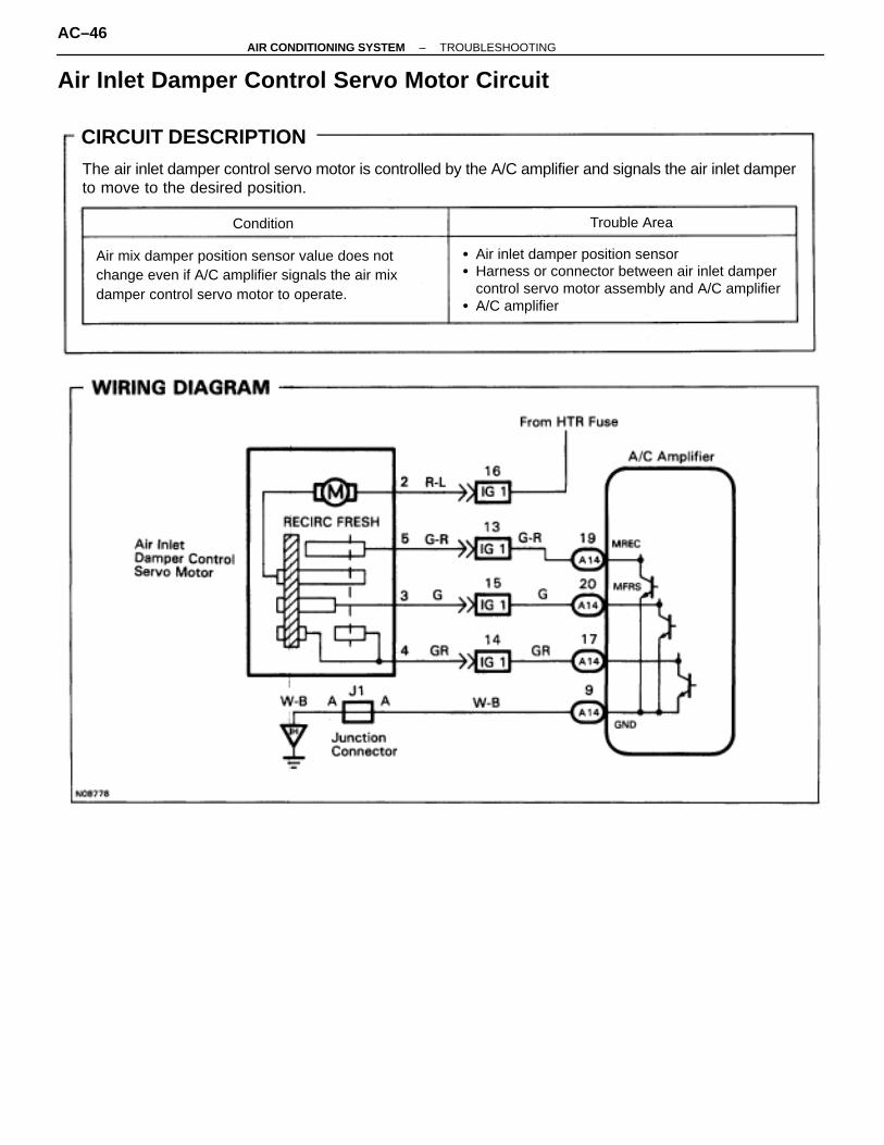
Air Inlet Damper Control Servo Motor Circuit
CIRCUIT DESCRIPTION
The air inlet damper control servo motor is controlled by the A/C amplifier and signals the air inlet damperto move to the desired position.
Condition Trouble Area
� Air inlet damper position sensor� Harness or connector between air inlet damper
control servo motor assembly and A/C amplifier � A/C amplifier
Air mix damper position sensor value does notchange even if A/C amplifier signals the air mixdamper control servo motor to operate.
AC–46–AIR CONDITIONING SYSTEM TROUBLESHOOTING
(See page AC–26).
(See page IN–30).
AC–22).
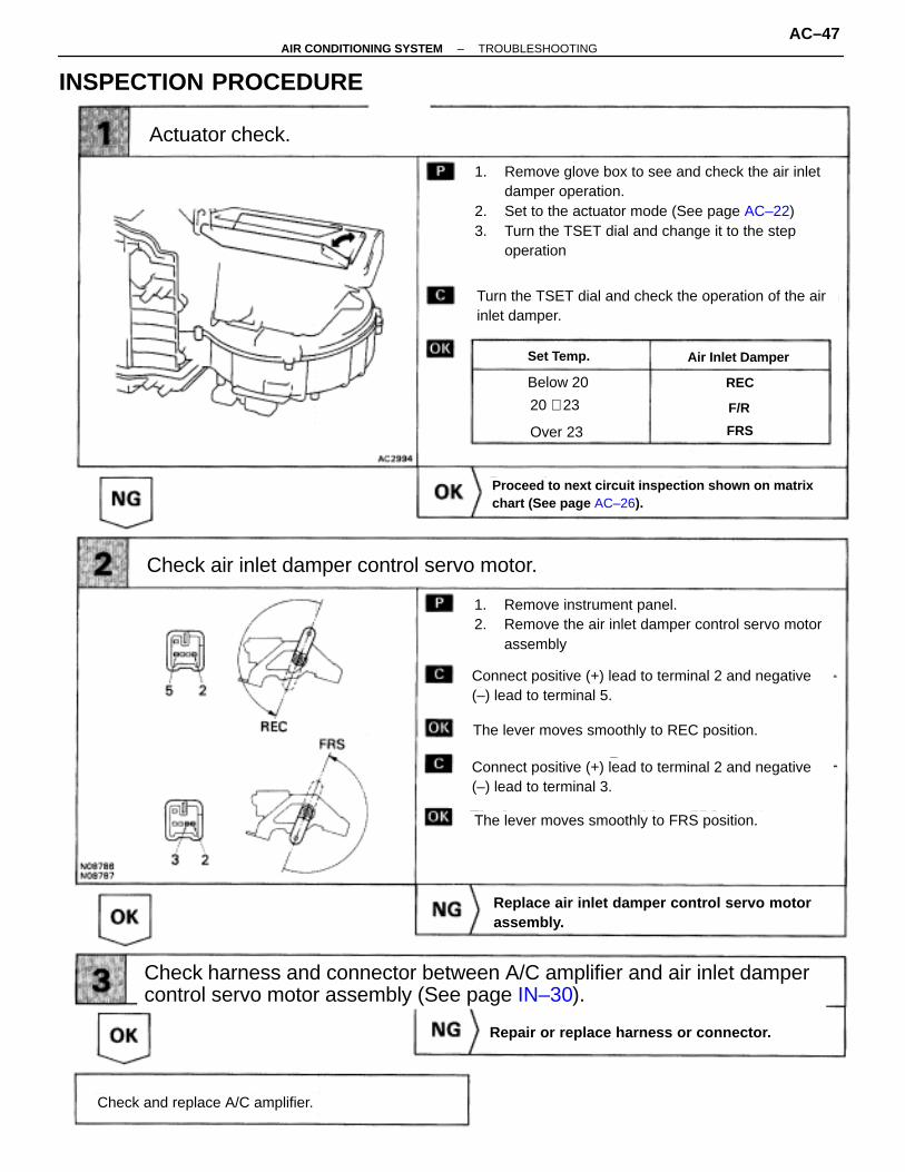
Actuator check.
Check air inlet damper control servo motor.
Check and replace A/C amplifier.
Repair or replace harness or connector.
Replace air inlet damper control servo motorassembly.
Check harness and connector between A/C amplifier and air inlet dampercontrol servo motor assembly (See page IN–30).
Proceed to next circuit inspection shown on matrixchart (See page AC–26).
Turn the TSET dial and check the operation of the airinlet damper.
The lever moves smoothly to FRS position.
The lever moves smoothly to REC position.
Set Temp. Air Inlet Damper
Below 20
Over 23
20 ∼ 23
REC
F/R
FRS
1. Remove glove box to see and check the air inletdamper operation.
2. Set to the actuator mode (See page AC–22)3. Turn the TSET dial and change it to the step
operation
1. Remove instrument panel.2. Remove the air inlet damper control servo motor
assembly
Connect positive (+) lead to terminal 2 and negative(–) lead to terminal 3.
Connect positive (+) lead to terminal 2 and negative(–) lead to terminal 5.
INSPECTION PROCEDURE
–AIR CONDITIONING SYSTEM TROUBLESHOOTINGAC–47

Blinking Light LO HI Air Outlet Damper Position Sensor CircuitCIRCUIT DESCRIPTION
This sensor detects the position of the air mixdamper and sends the appropriate signals to theA/C amplifier.The position sensor is built into the air outletdamper control servo motor assembly.
Trouble AreaDiagnostic Sensor Check Detecting ConditionLight
LO
HI
Short to ground or power source circuit in airoutlet damper position sensor circuit.
Air outlet damper position sensor value doesnot change even if A/C amplifier signals the airoutlet damper control servo motor to move.
� Air outlet damper position sensor� Harness or connector between air outlet
damper control servo motor assembly andA/C amplifier
� A/C amplifier
AC–48–AIR CONDITIONING SYSTEM TROUBLESHOOTING

(See page IN–30).
AC–50,
Check voltage between terminals TPM and SG of A/C amplifier connector.
Check and replace A/C amplifier.
Repair or replace harness or connector.
Check harness and connector between A/C amplifier and max. cooldamper control servo motor assembly (See page IN–30).
Replace max. cool damper control servo motorassembly.
Check air outlet damper position sensor.
Proceed to next circuit inspection shown on matrixchart (See page AC–26). However, if the light is stillblinking, check and replace A/C amplifier.
ResistanceDamper Position
Resistance: 4.7 ∼ 7.2 k�
While operating air outlet damper control servo motor,as in the procedure on page AC–50, measure resist-ance between terminals TPM and SG of air outlet servomotor assembly connector.Resistance
HINT: As the air outlet servo motor moves from FACE sideto DEF side, the resistance decreases gradually without interruption.
Measure resistance between terminals 4 and 5 of airoutlet damper control servo motor assembly connector.
1. Remove instrument panel.2. Disconnect air outlet damper control servo motor as–
sembly connector.
HINT: As the air outlet damper control servo motor is moved from VENT side to DEF side, the voltage decreases gradually without interruption.
Mode Switch Voltage
1. Remove A/C amplifier with connectors still con–nected.
2. Turn ignition switch ON
FACE
FACE
DEF
DEF
INSPECTION PROCEDURE
–AIR CONDITIONING SYSTEM TROUBLESHOOTINGAC–49
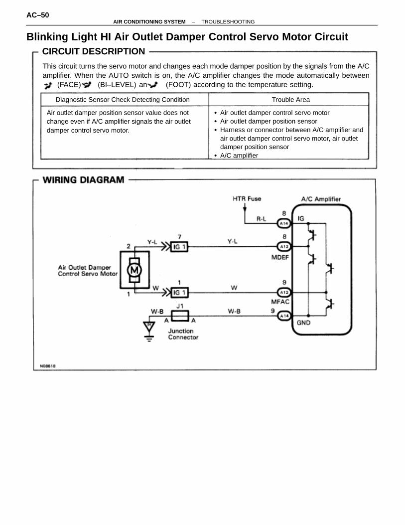
Blinking Light HI Air Outlet Damper Control Servo Motor CircuitCIRCUIT DESCRIPTION
This circuit turns the servo motor and changes each mode damper position by the signals from the A/Camplifier. When the AUTO switch is on, the A/C amplifier changes the mode automatically between
(FACE), (BI–LEVEL) and (FOOT) according to the temperature setting.
Trouble AreaDiagnostic Sensor Check Detecting Condition
� Air outlet damper control servo motor� Air outlet damper position sensor� Harness or connector between A/C amplifier and
air outlet damper control servo motor, air outlet damper position sensor
� A/C amplifier
Air outlet damper position sensor value does not change even if A/C amplifier signals the air outlet damper control servo motor.
AC–50–AIR CONDITIONING SYSTEM TROUBLESHOOTING
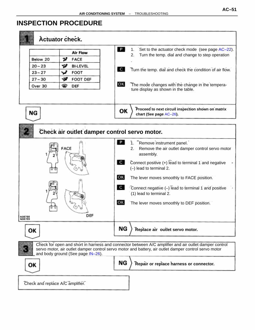
INSPECTION PROCEDURE
AC–22).
Check and replace A/C amplifier.
Repair or replace harness or connector.
Check for open and short in harness and connector between A/C amplifier and air outlet damper controlservo motor, air outlet damper control servo motor and battery, air outlet damper control servo motorand body ground (See page IN–26).
Replace air outlet servo motor.
Check air outlet damper control servo motor.
Proceed to next circuit inspection shown on matrixchart (See page AC–26).
Actuator check.
Turn the temp. dial and check the condition of air flow.
The mode changes with the change in the tempera-ture display as shown in the table.
The lever moves smoothly to DEF position.
The lever moves smoothly to FACE position.
Connect positive (+) lead to terminal 1 and negative(–) lead to terminal 2.
Connect negative (–) lead to terminal 1 and positive(1) lead to terminal 2.
1. Remove instrument panel.2. Remove the air outlet damper control servo motor
assembly.
1. Set to the actuator check mode (see page AC–22).2. Turn the temp. dial and change to step operation.
–AIR CONDITIONING SYSTEM TROUBLESHOOTINGAC–51

Back Up Power Source Circuit
CIRCUIT DESCRIPTIONThis is the back up power source for the A/C amplifier. Power is supplied even when the ignition switch is offand is used for diagnostic sensor check memory, etc.
AC–52–AIR CONDITIONING SYSTEM TROUBLESHOOTING

INSPECTION PROCEDURE
Remove the A/C amplifier with connector still con-ected.
Measure voltage between terminal + B of air condi-tioner control assembly connector and body ground.
Voltage: Battery positive voltage
Proceed to next circuit inspection shown on matrixchart (See page AC–26).
Remove ECU–B fuse from J/B No. 1.
Check continuity of ECU–B fuse.
Continuity
Check ECU–B fuse.
Check for short in all the harness and compo-nents to the ECU–B fuse (See attached wiring diagram).
Check voltage between terminal +B of A/C amplifier connector andbody ground.
Check and repair harness and connector betweenA/C amplifier and battery.
–AIR CONDITIONING SYSTEM TROUBLESHOOTINGAC–53

IG Power Source Circuit
CIRCUIT DESCRIPTIONThis is the power source for the A/C amplifier and servo motors, etc.
INSPECTION PROCEDURE
Remove the A/C amplifier with connector still con-nected
Voltage: Battery positive voltage
1. Turn ignition switch ON.2. Measure voltage between terminals IG and GND
of A/C amplifier.
Proceed to next circuit inspection shown on matrixchart (See page AC–26).
Go to step
Check voltage between terminals IG and GND of A/C amplifier connector .
AC–54–AIR CONDITIONING SYSTEM TROUBLESHOOTING

Check continuity between terminal GND of A/C amplifier and body ground.
Measure resistance between terminal GND of A/Camplifier and body ground.
Remove HTR fuse from J/B No. 1.
Check continuity of HTR fuse.
Continuity
Check for short in all the harness and compo-nents to the HTR fuse (See attached wiring diagram).
Check and repair harness and connector betweenA/C amplifier and battery.
Check HTR fuse.
Repair or replace harness or connector.
Resistance: O � �continuity)
–AIR CONDITIONING SYSTEM TROUBLESHOOTINGAC–55
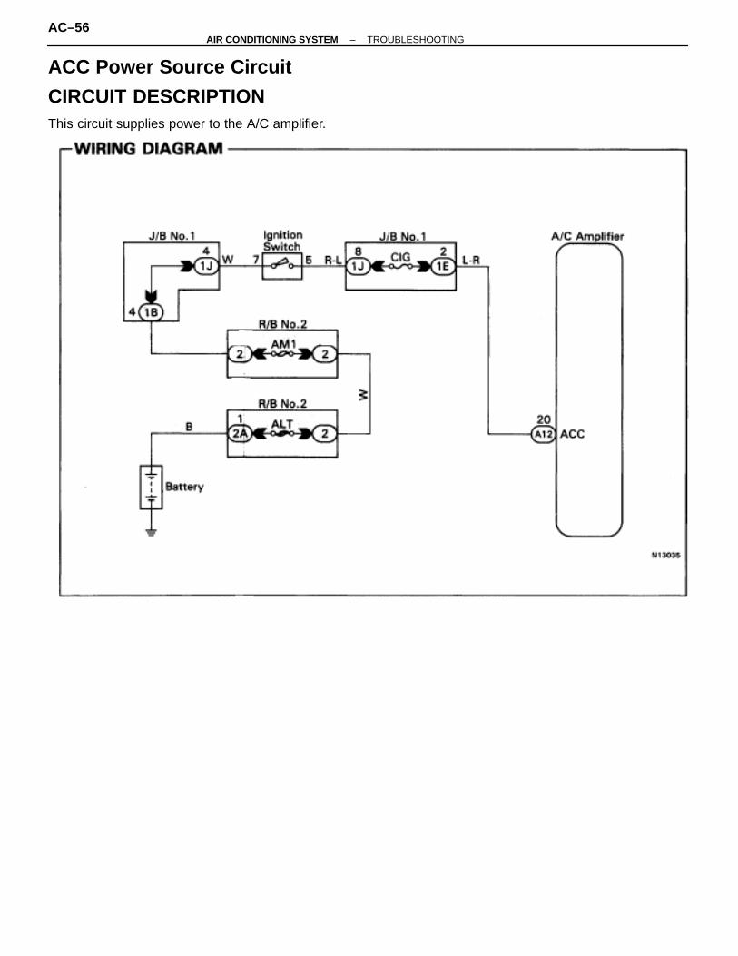
ACC Power Source Circuit
CIRCUIT DESCRIPTIONThis circuit supplies power to the A/C amplifier.
AC–56–AIR CONDITIONING SYSTEM TROUBLESHOOTING
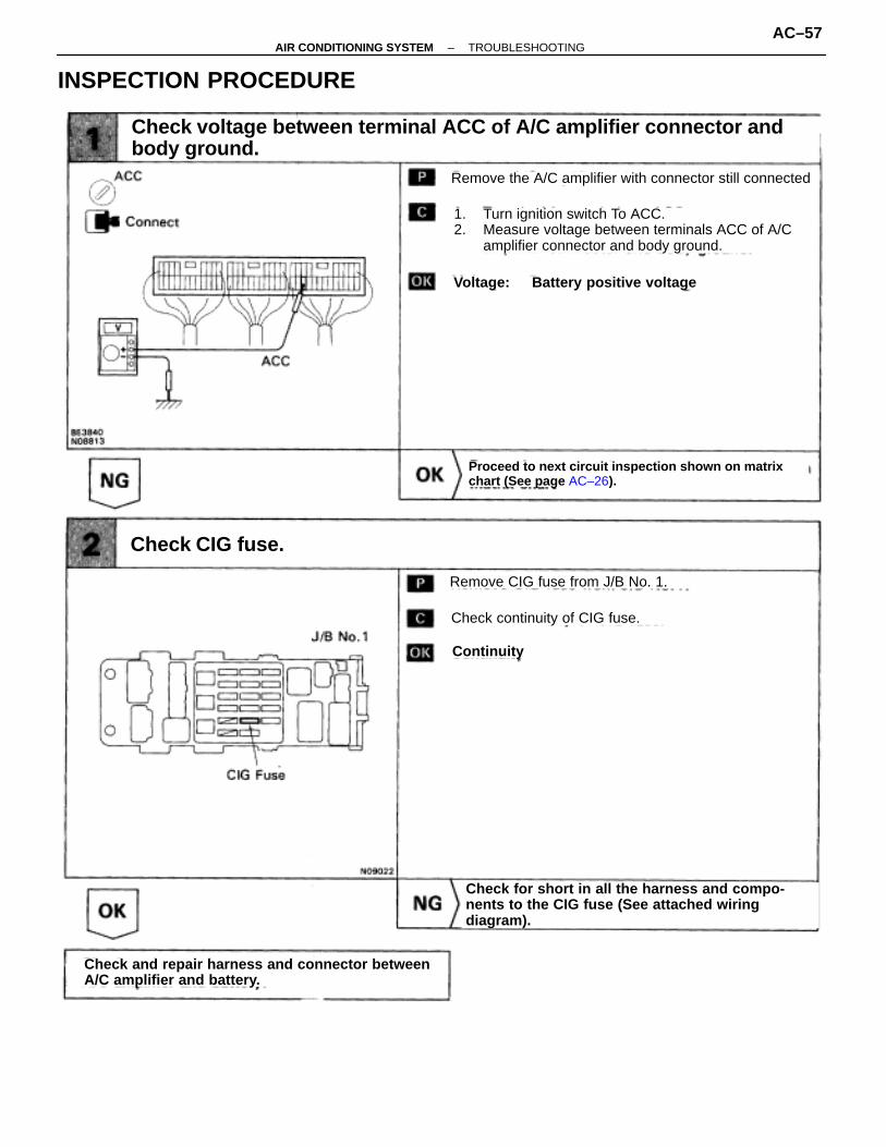
INSPECTION PROCEDURE
Check voltage between terminal ACC of A/C amplifier connector andbody ground.
Remove the A/C amplifier with connector still connected
Voltage: Battery positive voltage
1. Turn ignition switch To ACC.2. Measure voltage between terminals ACC of A/C
amplifier connector and body ground.
Remove CIG fuse from J/B No. 1.
Check continuity of CIG fuse.
Continuity
Proceed to next circuit inspection shown on matrixchart (See page AC–26).
Check CIG fuse.
Check for short in all the harness and compo-nents to the CIG fuse (See attached wiring diagram).
Check and repair harness and connector betweenA/C amplifier and battery.
–AIR CONDITIONING SYSTEM TROUBLESHOOTINGAC–57

Heater Relay Circuit
CIRCUIT DESCRIPTIONThe heater relay is switched on by signals from the A/C amplifier and switches power to the blower motor.
AC–58–AIR CONDITIONING SYSTEM TROUBLESHOOTING

Check voltage between terminal HR of A/C amplifier connector andbody ground.
Check heater relay.
Proceed to next circuit inspection shown on matrixchart (See page AC–26).
Check HTR fuse.
Check and repair harness and connector betweenA/C amplifier and battery.
Check for short in all the harness and compo-nents to the HTR fuse (See attached wiringdiagram).
Replace heater relay.
Remove the A/C amplifier with connectors still con-nected
Measure voltage between terminals HR of A/C ampli-fier connector and body ground when ignition switch isON and OFF.
VoltageIgnition Switch
Check continuity between each pair of terminals ofheater relay shown below.
1. Apply battery positive voltage between terminals 1 and 3.
2. Check continuity between each pair of terminal shown below.
Terminals 2 and 4
Terminals 4 and 5
No continuity
Continuity
Terminals 4 and 5
Terminals 1 and 3Terminals 2 and 4
No continuity
Continuity
OFF
ON
OV
Blower OFF
Blower ON Below 1.O V
Battery positive voltage
INSPECTION PROCEDURE
–AIR CONDITIONING SYSTEM TROUBLESHOOTINGAC–59

Blower Motor Circuit
CIRCUIT DESCRIPTIONThis is the power source for the blower motor.
INSPECTION PROCEDURE
Check voltage between terminal BLW of A/C amplifier connector andbody ground.
Proceed to next circuit inspection shown on matrixchart (See page AC–26).
Go to step
Remove the A/C amplifier with connector still con-nected
Voltage: 1 – 3 V
1. Turn ignition switch To ON.2. Operate blower motor.3. Measure voltage between terminals BLW of A/C
amplifier connector and body ground.
AC–60–AIR CONDITIONING SYSTEM TROUBLESHOOTING

(See page AC–99).
Check blower motor.
Go to step
Replace blower motor.
Check blower motor control relay.
Replace blower motor control relay.
Repair or replace harness or connector
Remove blower motor control relay with connectorsstill connected
1. Turn ignition switch To ON.2. Operate blower motor.
Terminals Standard Value
Continuity
Battery PositiveVoltage
Battery PositiveVoltage
Battery PositiveVoltage
Connect positive (+) lead to terminal 2 of blower motor connector, negative (–) lead to terminal 1.
Remove blower motor control (see page AC–99).
Blower motor operates smoothly.
–AIR CONDITIONING SYSTEM TROUBLESHOOTINGAC–61

Compressor Circuit
CIRCUIT DESCRIPTIONThe A/C amplifier outputs the magnetic clutch ON signal from terminal MGC to the ECM. When the ECM re-ceives this signal, it sends a signal from terminal ACMG and switches the air conditioning magnetic clutch relayON, thus turning the air conditioning compressor magnetic clutch ON.
AC–62–AIR CONDITIONING SYSTEM TROUBLESHOOTING

Check voltage between terminal A/C IN of A/C amplifier connector andbody ground.
Check air conditioning compressor magnetic clutch.
Go to step
Check for open and short in harness and connector between air conditioner compressor and magnetic clutch relay (See page IN–30).
Repair or replace harness or connector.
Go to step
1. Remove A/C amplifier with connectors still connected.
2. Start the engine.
Check voltage between terminal A/C IN of A/C amplifi-er connector and body ground when magnetic clutch ison and off by A/C switch.
Magnetic Clutch Voltage
ON
OFF Below 1 V
Connect positive (+) lead connected to battery tomagnetic clutch connector terminal 4.
Disconnect magnetic clutch connector.
Magnetic clutch is energized.
Repair air conditioning compressor magneticclutch.
10 – 14 V
INSPECTION PROCEDURE
–AIR CONDITIONING SYSTEM TROUBLESHOOTINGAC–63

Go to step
Check and replace ECM.
Check voltage between terminal A/C of ECM and body ground.
Check voltage between terminal MGC of A/C amplifier connector andbody ground.
Magnetic Clutch Voltage
ON
OFF
Below 1 V
4 – 6 V
1. Remove A/C amplifier with connectors still connected.
2. Start the engine.
Check voltage between terminal A/C IN of A/C amplifi-er connector and body ground when magnetic clutch ison and off by A/C switch.
1. Remove the ECM with connectors still connected.
2. Turn ignition switch on.
Magnetic Clutch Voltage
ON
OFF
Below 1 V
10 – 14 V
Check and replace A/C amplifier.
Repair or replace harness or connector.
Check for open and short in harness and connector between A/C am-plifier and ECM (See page IN–30).
1. Push the A/C switch on.2. Measure voltage between terminal A/C of the
ECM connector and body ground.
AC–64–AIR CONDITIONING SYSTEM TROUBLESHOOTING

Remove magnetic clutch relay from R/B No. 2.
Check continuity between each pair of terminalsshown below of magnetic clutch relay.
Terminals 1 and 2
Terminals 3 and 5
Terminals 3 and 5
No continuity
Continuity
Replace magnetic relay.
Check and replace the ECM.
Repair or replace harness or connector.
A/C Switch Voltage
ON
OFF
Check for open and short in harness and connector between the ECM andbattery (See page IN–30).
Approx. 1.3. V
Approx. 75 �
Battery positive voltage
Check magnetic clutch relay.
Check voltage between terminal ACMG of ECM and body ground.
1. Apply battery positive voltage between terminals 1 and 2.
2. Check continuity between terminals 3 and 5.
1. Remove the ECM with connectors still connected.
2. Turn ignition switch on.
1. Turn fan speed control dial (Lo, Med or Hi).2. Measure voltage between terminal ACMG of the
ECM connector and body ground.
Proceed to next circuit inspection shown on matrixchart (See page AC–26).
∼ 1.3 V
–AIR CONDITIONING SYSTEM TROUBLESHOOTINGAC–65

A C Control Assembly Circuit
CIRCUIT DESCRIPTIONThis circuit includes the control switch circuit and the LED circuit in the A/C control Assembly.The A/C amplifier always searches which switch is operated and drives the LED according to A/C control opera-tion or diagnostic sensor check operation.
AC–66–AIR CONDITIONING SYSTEM TROUBLESHOOTING

INSPECTION PROCEDURE
Check the each LED lights up when the applicable switch is operated.
Proceed to next circuit inspection shown on matrixchart (See page AC–26).
Check voltage between terminal for LED (OFF) and terminal H12–9 ofA/C control assembly.
Check continuity of harness between A/C amplifier and A/C controlassembly.
Go to step
Repair or replace harness or connector.
Repair or replace A/C control assembly.
Switch
ON
OFF
Below 1.0 V
10 ∼ 14 V
Voltage
All LED OFF Check IG switch circuit.
1. Push the switch on or OFF.2. Check voltage between terminal for the LED
(OFF) and terminal H12–9 of A/C control assembly.
1. Push each switch or turn fan sped dial on theA/C control assembly.
2. Check LED lighting according to switch operation.
–AIR CONDITIONING SYSTEM TROUBLESHOOTINGAC–67
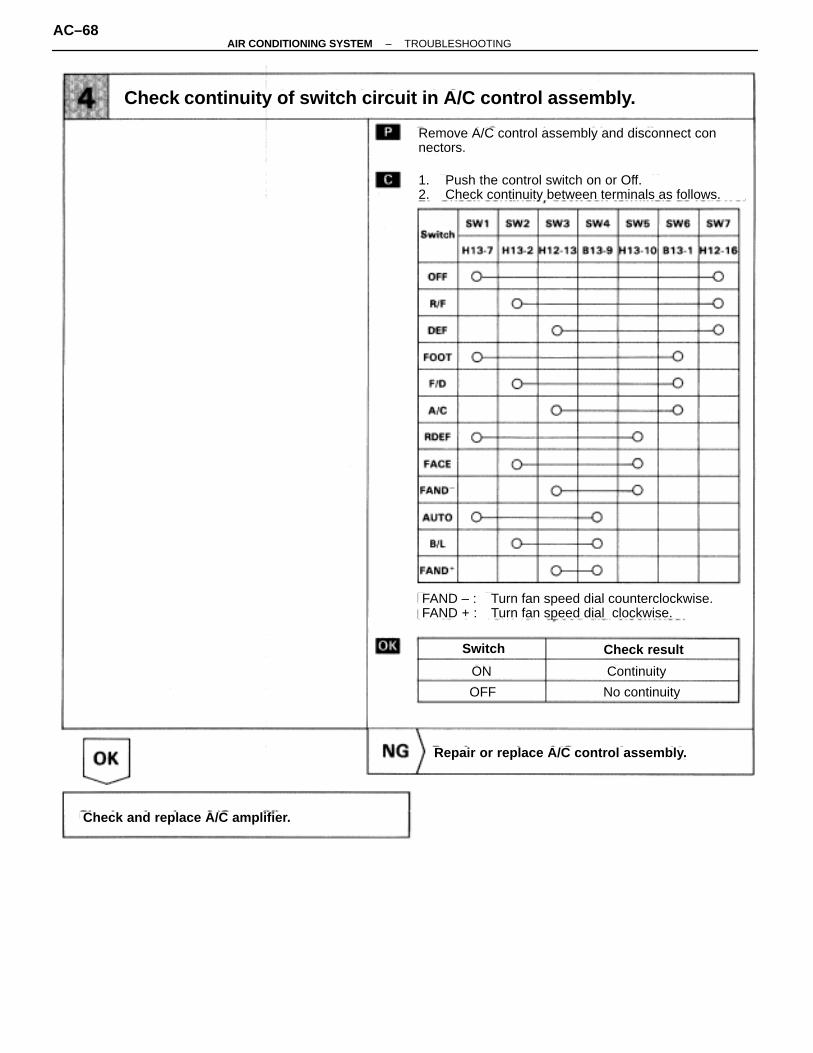
Repair or replace A/C control assembly.
Check and replace A/C amplifier.
Switch Check result
ON
OFF No continuity
Continuity
Remove A/C control assembly and disconnect connectors.
Check continuity of switch circuit in A/C control assembly.
1. Push the control switch on or Off.2. Check continuity between terminals as follows.
FAND – : Turn fan speed dial counterclockwise.FAND + : Turn fan speed dial clockwise.
AC–68–AIR CONDITIONING SYSTEM TROUBLESHOOTING

Temperature Set Dial Circuit
CIRCUIT DESCRIPTIONWhen temperature set dial is turned, the voltage of TSET terminal will change. A/C amplifier searches for thischange and controls the room temperature according to the temperature set.
–AIR CONDITIONING SYSTEM TROUBLESHOOTINGAC–69

INSPECTION PROCEDURE
Check voltage of TSET terminal on A/C amplifier.
Check voltage of terminal on A/C control assembly.
Check harness and connectors for S5 and SG signal.
Proceed to next circuit inspection shown onmatrix chart (See page AC–26).
Replace A/C control assembly.
Repair or replace harness or connectors between A/C amplifier and A/C control assembly.
Repair or replace harness or connectors between A/C amplifier and A/C control assembly.
VoltageCheck Terminals
VoltageSet Temperature
1. Turn temperature set dial. 2. Check voltage between terminals TSET and SG
of A/C amplifier.
Remove A/C amplifier with connectors still connected.
Remove A/C control assembly with connectors still connected.
Check voltage between following terminal and H12–9(GND) of A/C control assembly connectors.
AC–70–AIR CONDITIONING SYSTEM TROUBLESHOOTING

REFRIGERANT SYSTEM INSPECTION WITH MANIFOLD GAUGE SETThis is a method in which the trouble is located by using a manifold gauge set.(See “USE OF MANIFOLD GAUGE SET” on page AC–11)Read the manifold gauge pressure when the following conditions are established:(a) Temperature at the air inlet with the switch set at RECIRC is 30–35 °C (86–95 °F)(b) Engine running at 1,500 rpm(c) Blower speed control switch set at high(d) Temperature control set at max. cool
HINT: It should be noted that the gauge indications may vary slightly due to ambient temperature condi-tions.
1. NORMALLY FUNCTIONING REFRIGERATION SYSTEMGauge reading:
Low pressure side:0.15–0.25 MPa (1.5–2.5 kgf/cm 2)
High pressure side:1.37–1.57 MPa (14–16 kgf/cm 2)
–AIR CONDITIONING SYSTEM TROUBLESHOOTINGAC–71
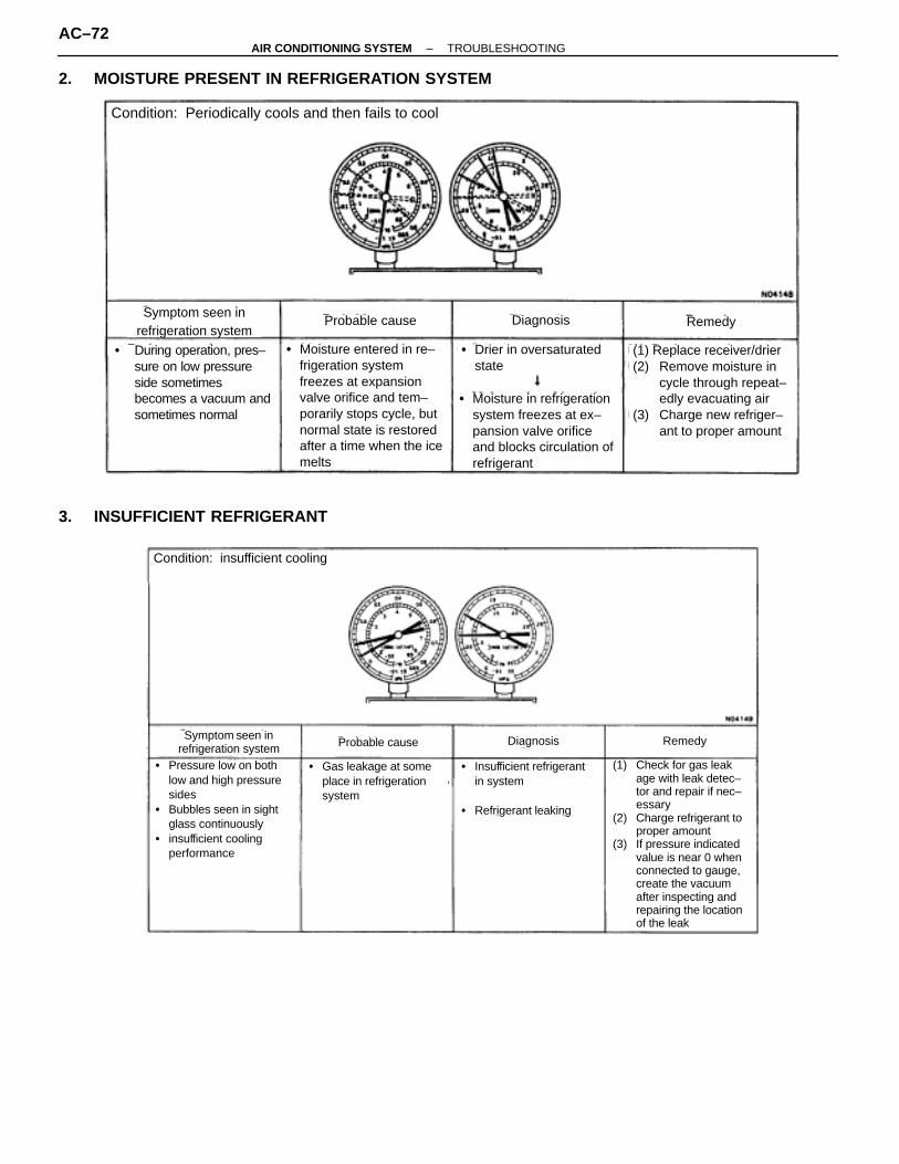
2. MOISTURE PRESENT IN REFRIGERATION SYSTEM
Symptom seen inrefrigeration system
Probable cause Diagnosis Remedy
� During operation, pres–sure on low pressure side sometimes becomes a vacuum andsometimes normal
� Moisture entered in re–frigeration system freezes at expansion valve orifice and tem–porarily stops cycle, but normal state is restored after a time when the ice melts
(1) Replace receiver/drier(2) Remove moisture in
cycle through repeat–edly evacuating air
(3) Charge new refriger–ant to proper amount
� Drier in oversaturatedstate
� Moisture in refrigeration system freezes at ex–pansion valve orifice and blocks circulation of refrigerant
Condition: Periodically cools and then fails to cool
3. INSUFFICIENT REFRIGERANT
Symptom seen inrefrigeration system
Condition: insufficient cooling
Probable cause Diagnosis Remedy
� Pressure low on bothlow and high pressuresides
� Bubbles seen in sightglass continuously
� insufficient coolingperformance
� Gas leakage at someplace in refrigeration system
� Insufficient refrigerant in system
� Refrigerant leaking
(1) Check for gas leakage with leak detec–tor and repair if nec–essary
(2) Charge refrigerant to proper amount
(3) If pressure indicated value is near 0 when connected to gauge, create the vacuumafter inspecting and repairing the location of the leak
AC–72–AIR CONDITIONING SYSTEM TROUBLESHOOTING

4. POOR CIRCULATION OF REFRIGERANT
Symptom seen inrefrigeration system Probable cause Diagnosis Remedy
� Pressure low on bothlow and high pressuresides
� Frost on tubes fromreceiver to unit
� Refrigerant flow obstructed by dirt inreceiver
� Receiver clogged � Replace receiver
Condition: insufficient cooling
5. REFRIGERANT DOES NOT CIRCULATE
Symptom seen inrefrigeration system Probable cause Diagnosis Remedy
� Vacuum indicated on low pressure side, very low pressure indicted on high pressure side
� Frost or dew seen on piping before and after receiver/drier or expan–sion valve
� Refrigerant flow obstructed by moisture or dirt in refrigeration system
� Refrigerant flow ob–structed by gas leakagefrom expansion valve heat sensing tube
� Refrigerant does not circulate
(1) Check heat sensing tube, expansion valve and ERP
(2) Clean out dirt inexpan–sion valve by blowing with airIf not able to remove dirt, replace expansion valve
(3) Replace receiver(4) Evacuate air and
charge new refrigerant to proper amount.for gas leakage from heat sensing tube, replace expansion valve.
–AIR CONDITIONING SYSTEM TROUBLESHOOTINGAC–73

6. REFRIGERANT OVERCHARGE OR INSUFFICIENT COOLING OF CONDENSER
Symptom seen inrefrigeration system
Probable cause Diagnosis Remedy
(1) Clean condenser(2) Check fan motor
operation(3) If (1) and (2) are in
normal state, check amount of refrigerant Charge proper amount of refrigerant
� Pressure too high on both low and high pressure sides
� No air bubbles seen through the sight of glass even when the engine rpm is lowered.
� Unable to develop sufficient performancedue to excessiverefrigerant in system
� Insufficient cooling of condenser
� Excessive refrigerant inin cycle → refrigerantovercharged
� Condenser coolinginsufficient → condenser fins clogged or fan motorfaulty
Condition: Insufficient Cooling
7. AIR PRESENT IN REFRIGERATION SYSTEM
Condition: insufficient cooling
Symptom seen inrefrigeration system
Probable cause Diagnosis Remedy
(1) Check compressor oil tosee if dirty or insufficient
(2) Evacuate air and chargenew refrigerant
� Pressure too high on both low and high pressure sides
� The low pressure piping ishot to the touch
� Bubbles seen in sightglass
� Air entered inrefrigeration system
� Air present inrefrigeration system
NOTE: These gauge indications are shown when the refrigerationsystem has been opened and the refrigerant charged withoutvacuum purging.
� Insufficient vacuumpurging
AC–74–AIR CONDITIONING SYSTEM TROUBLESHOOTING

8. EXPANSION VALVE IMPROPERLYMOUNTED/HEAT SENSING TUBE DEFECTIVE(OPENS TOO WIDE)
Symptom seen inrefrigeration system
Probable cause Diagnosis Remedy
(1) Check heat sensing tubeinstalled condition
(2) if (1) is normal, checkexpansion valveReplace if defective
� Pressure too high on both low and high pressure sides
� Frost or large amount ofdew on piping on lowpressure side
� Trouble in expansionvalve or heat sensing tubenot installed correctly
� Excessive refrigerant inlow pressure piping
Condition: Insufficient cooling
� Expansion valve openedtoo wide
9. DEFECTIVE COMPRESSION COMPRESSOR
Symptom seen inrefrigeration system
Probable cause Diagnosis Remedy
Condition: Does not cool
� Repair or replacecompressor
� Pressure too high on low pressure sides
� Pressure too low onhigh pressure side
� Internal leak incompressor
� Compression defective
� Valve leaking or broken,sliding parts
–AIR CONDITIONING SYSTEM TROUBLESHOOTINGAC–75

REFRIGERANT VOLUMEREFRIGERANT VOLUME INSPECTION1. RUN ENGINE AT APPROX. 1,500 RPM2. SET TEMPERATURE CONTROL AT MAX. COOL3. SET BLOWER SWITCH AT ”HI”4. SET AIR INLET CONTROL AT ”RECIRC”5. TURN A/C SWITCH ON6. FULLY OPEN DOORS7. INSPECT AMOUNT OF REFRIGERANT
Observe the sight glass on the liquid tube.
ÑÑÑÑÑÑ
ItemÑÑÑÑÑÑÑÑÑÑÑÑÑÑÑÑÑÑÑÑÑÑÑÑÑÑ
Symptom ÑÑÑÑÑÑÑÑÑÑÑÑÑÑÑÑÑÑ
Amount of refrigerant ÑÑÑÑÑÑÑÑÑÑÑÑÑÑÑÑÑÑÑÑÑÑÑÑÑÑÑÑ
RemedyÑÑÑÑÑÑÑÑÑÑÑÑÑÑÑ
1
ÑÑÑÑÑÑÑÑÑÑÑÑÑÑÑÑÑÑÑÑÑÑÑÑÑÑÑÑÑÑÑÑÑÑÑÑÑÑÑÑÑÑÑÑÑÑÑÑÑÑÑÑÑÑÑÑÑÑÑÑÑÑÑÑÑ
Bubbles present in sight glass
ÑÑÑÑÑÑÑÑÑÑÑÑÑÑÑÑÑÑÑÑÑÑÑÑÑÑÑÑÑÑÑÑÑÑÑÑÑÑÑÑÑÑÑÑÑ
Insufficient*
ÑÑÑÑÑÑÑÑÑÑÑÑÑÑÑÑÑÑÑÑÑÑÑÑÑÑÑÑÑÑÑÑÑÑÑÑÑÑÑÑÑÑÑÑÑÑÑÑÑÑÑÑÑÑÑÑÑÑÑÑÑÑÑÑÑÑÑÑÑÑ
(1) Check for gas leakage with gas leaktester and repair if necessary(2) Add refrigerant until bubbles dis–appear
ÑÑÑÑÑÑÑÑÑ
2ÑÑÑÑÑÑÑÑÑÑÑÑÑÑÑÑÑÑÑÑÑÑÑÑÑÑÑÑÑÑÑÑÑÑÑÑÑÑÑ
No bubbles present in sight glassÑÑÑÑÑÑÑÑÑÑÑÑÑÑÑÑÑÑÑÑÑÑÑÑÑÑÑ
None, sufficient or toomuch
ÑÑÑÑÑÑÑÑÑÑÑÑÑÑÑÑÑÑÑÑÑÑÑÑÑÑÑÑÑÑÑÑÑÑÑÑÑÑÑÑÑÑ
Refer to items 3 and 4
ÑÑÑÑÑÑÑÑÑÑÑÑÑÑÑ
3
ÑÑÑÑÑÑÑÑÑÑÑÑÑÑÑÑÑÑÑÑÑÑÑÑÑÑÑÑÑÑÑÑÑÑÑÑÑÑÑÑÑÑÑÑÑÑÑÑÑÑÑÑÑÑÑÑÑÑÑÑÑÑÑÑÑ
No temperature difference betweencompressor inlet and outlet
ÑÑÑÑÑÑÑÑÑÑÑÑÑÑÑÑÑÑÑÑÑÑÑÑÑÑÑÑÑÑÑÑÑÑÑÑÑÑÑÑÑÑÑÑÑ
Empty or nearly empty
ÑÑÑÑÑÑÑÑÑÑÑÑÑÑÑÑÑÑÑÑÑÑÑÑÑÑÑÑÑÑÑÑÑÑÑÑÑÑÑÑÑÑÑÑÑÑÑÑÑÑÑÑÑÑÑÑÑÑÑÑÑÑÑÑÑÑÑÑÑÑ
(1) Check for gas leakage with gas leaktester and repair if necessary(2) Add refrigerant until bubbles disap-pear
ÑÑÑÑÑÑÑÑÑ
4ÑÑÑÑÑÑÑÑÑÑÑÑÑÑÑÑÑÑÑÑÑÑÑÑÑÑÑÑÑÑÑÑÑÑÑÑÑÑÑ
Temperature between compressorinlet and outlet is noticeably different
ÑÑÑÑÑÑÑÑÑÑÑÑÑÑÑÑÑÑÑÑÑÑÑÑÑÑÑ
Correct or too muchÑÑÑÑÑÑÑÑÑÑÑÑÑÑÑÑÑÑÑÑÑÑÑÑÑÑÑÑÑÑÑÑÑÑÑÑÑÑÑÑÑÑ
Refer to items 5 and 6
ÑÑÑÑÑÑÑÑÑÑÑÑ
5ÑÑÑÑÑÑÑÑÑÑÑÑÑÑÑÑÑÑÑÑÑÑÑÑÑÑÑÑÑÑÑÑÑÑÑÑÑÑÑÑÑÑÑÑÑÑÑÑÑÑÑÑ
Immediately after air conditioning isturned off, refrigerant in sight glassstays clear
ÑÑÑÑÑÑÑÑÑÑÑÑÑÑÑÑÑÑÑÑÑÑÑÑÑÑÑÑÑÑÑÑÑÑÑÑ
Too muchÑÑÑÑÑÑÑÑÑÑÑÑÑÑÑÑÑÑÑÑÑÑÑÑÑÑÑÑÑÑÑÑÑÑÑÑÑÑÑÑÑÑÑÑÑÑÑÑÑÑÑÑÑÑÑÑ
(1) Discharge refrigerant(2) Evacuate air and charge properamount of purified refrigerant
ÑÑÑÑÑÑÑÑÑÑÑÑ
6ÑÑÑÑÑÑÑÑÑÑÑÑÑÑÑÑÑÑÑÑÑÑÑÑÑÑÑÑÑÑÑÑÑÑÑÑÑÑÑÑÑÑÑÑÑÑÑÑÑÑÑÑ
When air conditioning is turned off,refrigerant foams and then staysclear
ÑÑÑÑÑÑÑÑÑÑÑÑÑÑÑÑÑÑÑÑÑÑÑÑÑÑÑÑÑÑÑÑÑÑÑÑ
CorrectÑÑÑÑÑÑÑÑÑÑÑÑÑÑÑÑÑÑÑÑÑÑÑÑÑÑÑÑÑÑÑÑÑÑÑÑÑÑÑÑÑÑÑÑÑÑÑÑÑÑÑÑÑÑÑÑ
––
* Bubbles in the sight glass with ambient temperatures higher than usual can be considered normal if cooling is sufficient.
REFRIGERANT CHARGE VOLUMESpecified amount:
700 ± 50 g (24.96 ± 1.76 oz.)
AC–76–AIR CONDITIONING SYSTEM REFRIGERANT VOLUME

DRIVE BELT TENSIONDRIVE BELT TENSION INSPECTION1. INSPECT DRIVE BELT’S INSTALLATION CONDITION
Check that drive belt fits properly in the ribbed grooves.
2. INSPECT DRIVE BELT TENSIONCheck that the tension is within A range on the auto tensionerscale.If the tension is not within the A range on the scale, replacethe belt with a new one.HINT: When replacing the drive belt with a new one, the belt’stension should be within the B range on the belt tensionerscale.
IDLE–UP SPEEDIDLE UP SPEED INSPECTION1. WARM UP ENGINE2. INSPECT IDLE SPEED
Put gear shift in neutral.2JZ–GE (M/T)
ÑÑÑÑÑÑÑÑÑÑÑÑÑÑÑÑÑÑÑÑÑÑMagnetic clutch condition
ÑÑÑÑÑÑÑÑÑÑÑÑÑÑÑÑÑÑÑÑÑÑÑÑStandard idle speed (RPM)
ÑÑÑÑÑÑÑÑÑÑÑÑÑÑÑÑÑÑÑÑÑÑ
Not engaged ÑÑÑÑÑÑÑÑÑÑÑÑÑÑÑÑÑÑÑÑÑÑÑÑ
Approx. 700
ÑÑÑÑÑÑÑÑÑÑÑÑÑÑÑÑÑÑÑÑÑÑ
Engaged ÑÑÑÑÑÑÑÑÑÑÑÑÑÑÑÑÑÑÑÑÑÑÑÑ
Approx. 900
2JZ–GE (A/T)ÑÑÑÑÑÑÑÑÑÑÑÑÑÑÑÑÑÑÑÑÑÑ
Magnetic clutch conditionÑÑÑÑÑÑÑÑÑÑÑÑÑÑÑÑÑÑÑÑÑÑÑÑ
Standard idle speed (RPM)ÑÑÑÑÑÑÑÑÑÑÑÑÑÑÑÑÑÑÑÑÑÑNot engaged
ÑÑÑÑÑÑÑÑÑÑÑÑÑÑÑÑÑÑÑÑÑÑÑÑApprox. 700ÑÑÑÑÑÑÑÑÑÑÑ
ÑÑÑÑÑÑÑÑÑÑÑÑÑÑÑÑÑÑÑÑÑÑ
EngagedÑÑÑÑÑÑÑÑÑÑÑÑÑÑÑÑÑÑÑÑÑÑÑÑÑÑÑÑÑÑÑÑÑÑÑÑ
Approx. 800
2JZ–GTEÑÑÑÑÑÑÑÑÑÑÑÑÑÑÑÑÑÑÑÑÑÑ
Magnetic clutch condition ÑÑÑÑÑÑÑÑÑÑÑÑÑÑÑÑÑÑÑÑÑÑÑÑ
Standard idle speed (RPM)ÑÑÑÑÑÑÑÑÑÑÑÑÑÑÑÑÑÑÑÑÑÑ
Not engagedÑÑÑÑÑÑÑÑÑÑÑÑÑÑÑÑÑÑÑÑÑÑÑÑ
Approx. 650ÑÑÑÑÑÑÑÑÑÑÑÑÑÑÑÑÑÑÑÑÑÑEngaged
ÑÑÑÑÑÑÑÑÑÑÑÑÑÑÑÑÑÑÑÑÑÑÑÑApprox. 800
–AIR CONDITIONING SYSTEM DRIVE BELT TENSIONAC–77

REFRIGERANT LINESTIGHTENING TORQUE OF REFRIGERATION LINES
ON–VEHICLE INSPECTION1. INSPECT HOSES AND TUBES FOR LEAKAGE
Using a gas leak tester, check for leakage of refrigerant.2. INSPECT HOSE AND TUBE CONNECTIONS FOR
LOOSENESS
AC–78–AIR CONDITIONING SYSTEM REFRIGERANT LINES

REFRIGERANT LINES REPLACEMENT1. DISCHARGE REFRIGERANT IN REFRIGERATION
SYSTEM2. REPLACE FAULTY TUBE OR HOSE
NOTICE: To prevent the intrusion of moisture or dirt,caps should be placed on hose or tube ends immediate-ly.
3. TORQUE CONNECTIONS TO SPECIFIED TORQUENOTICE: Connections should not be torqued tighter thanthe specified torque.Compressor X Suction tubeTorque: 10 N ⋅m (100 kgf ⋅cm, 7 ft ⋅lbf)
Compressor X Discharge tubeTorque: 10 N ⋅m (100 kgf ⋅cm, 7 ft ⋅lbf)
Condenser X Discharge tubeTorque: 10 N ⋅m (100 kgf ⋅cm, 7 ft ⋅lbf)
Condenser X Liquid tubeTorque: 10 N ⋅m (100 kgf ⋅cm, 7 ft ⋅lbf)
Receiver X Liquid tubeTorque: 5.4 N ⋅m (55 kgf ⋅cm, 48 in. ⋅lbf)
A/C unit X Liquid tubeTorque: 10 N ⋅m (100 kgf ⋅cm, 7 ft ⋅lbf)
A/C unit X Suction tubeTorque: 10 N ⋅m (100 kgf ⋅cm, 7 ft ⋅lbf)
Evaporator X Expansion valveTorque: 5.4 N ⋅m (55 kgf ⋅cm, 48 in. ⋅lbf)
Discharge linesTorque: 10 N ⋅m (100 kgf ⋅cm, 7 ft ⋅lbf)
Liquid linesTorque: 10 N ⋅m (100 kgf ⋅cm, 7 ft ⋅lbf)
Suction linesTorque: 10 N ⋅m (100 kgf ⋅cm, 7 ft ⋅lbf)
4. EVACUATE AIR IN REFRIGERATION SYSTEM ANDCHARGE WITH REFRIGERANTSpecified amount:
700 ± 50 g (24.96 ± 1.76 oz.)
5. INSPECT FOR LEAKAGE OF REFRIGERANTUsing a gas leak tester, check for leakage of refrigerant.
6. INSPECT AIR CONDITIONING OPERATION
–AIR CONDITIONING SYSTEM REFRIGERANT LINESAC–79

AIR CONDITIONING UNITAIR CONDITIONING UNIT REMOVAL1. DISCHARGE REFRIGERANT IN REFRIGERATION
SYSTEMINSTALLATION HINT: Evacuate air from refrigeration sys-tem.Charge system with the refrigerant and inspect for leakageof refrigerant.Specified amount:
700 ± 50 g (24.96 ± 1.76 oz.)
2. DRAIN ENGINE COOLANT FROM RADIATOR ANDENGINE COOLANT DRAIN COCK
3. REMOVE ENGINE WIRE HARNESS BRACKETMOUNTING BOLT
4. REMOVE BRAKE TUBE BRACKET MOUNTING BOLTSFROM DASH PANEL
5. REMOVE WATER HOSE FROM HEATER RADIATOR6. REMOVE INSULATOR RETAINER
Remove the 2 bolts and the insulator retainer.
7. REMOVE LIQUID TUBE AND SUCTION TUBE(a) w/ ABS:
Remove the ABS actuator.(See page BR–44)
(b) Remove the liquid tube and suction tube.Torque: 10 N ⋅m (100 kgf ⋅cm, 7 ft ⋅lbf)
INSTALLATION HINT: Lubricate the new O–rings with com-pressor oil and install tubes.
8. REMOVE PLATE COVERRemove the 2 bolts and the plate cover.
9. REMOVE INSTRUMENT PANEL AND REINFORCEMENT(See page BO–45)
AC–80–AIR CONDITIONING SYSTEM AIR CONDITIONING UNIT

10. REMOVE HEATER TO REGISTER NO. 3 DUCTRemove the 3 screws and the heater to register No. 3 duct.
11. REMOVE A/C UNIT(a) Disconnect connectors from the unit.(b) Remove the 6 bolts and the A/C unit.
INSTALLATION HINT: Pull the drain hose of the A/C unit for-ward until the yellow paint on the hose is visible in the enginecompartment.Insert the drain hose into the engine compartment hose untilthe matchmarks are aligned.
–AIR CONDITIONING SYSTEM AIR CONDITIONING UNITAC–81

AIR CONDITIONING UNIT DISASSEMBLY
AC–82–AIR CONDITIONING SYSTEM AIR CONDITIONING UNIT

1. REMOVE AIR INLET SERVOMOTOR(a) Disconnect the connector.(b) Disconnect the control link.(c) Remove the 3 screws and the air inlet servomotor.2. REMOVE BLOWER MOTOR CONTROL RELAY(a) Disconnect the connector.(b) Remove the 3 screws and the blower motor control relay.3. REMOVE BLOWER MOTOR(a) Disconnect the connector.(b) Using a torx driver, remove the blower motor.4. REMOVE EVAPORATOR(a) Remove the A/C unit wire harness.(b) Remove the foot air duct.(c) Remove the A/C unit block joint.(d) Remove the 6 screws and down and the lower cover.(e) Remove the 4 screws and the evaporator cover.
(f) Pull out the evaporator.
(g) Pull out the evaporator sensor from the evaporator.
(h) Using a hexagon wrench, remove the 2 bolts and separatethe evaporator and expansion valve.Torque: 5.4 N ⋅m (55 kgf ⋅cm, 48 in. ⋅lbf)
INSTALLATION HINT: If the evaporator was replaced, addcompressor oil to the compressor.Add 40 cc (1.4 fl.oz)Compressor oil
ND–OIL 8 or equivalent
–AIR CONDITIONING SYSTEM AIR CONDITIONING UNITAC–83

5. REMOVE AIR MIX SERVOMOTO(a) Remove the defroster duct.(b) Remove the 3 screws and the water valve cover.(c) Disconnect the connector.(d) Disconnect the control link.(e) Remove the 2 screws and the air mix servomotor.
6. REMOVE HEATER RADIATOR AND WATER VALVE(a) Remove the 2 screws and the plate.(b) Remove the 2 screws and the clamp.(c) Remove the 3 screws.(d) Pull out the heater radiator with the water valve.
(e) Remove the 2 screws and water valve from the heaterradiator.
7. REMOVE HEATER AIR DUCTRemove the 2 screws and the defroster air duct.
8. REMOVE VENT AIR DUCT(a) Disconnect the control link.(b) Remove the 2 screws and the vent air duct.
9. REMOVE ENGINE COOLANT TEMPERATURE SENSOR(a) Disconnect the connector.(b) After pulling off the clamp, pull out the sensor.10. REMOVE AIR OUTLET SERVOMOTOR(a) Disconnect the connector.(b) Remove the 3 screws and the air outlet servomotor.
AC–84–AIR CONDITIONING SYSTEM AIR CONDITIONING UNIT
AIR CONDITIONING UNIT ASSEMBLYAssembly is in the reverse order of disassembly.
AIR CONDITIONING UNIT INSTALLATIONInstallation is in the reverse order of removal.
COMPRESSORON–VEHICLE INSPECTIONMagnetic Clutch:
(See page AC–62)
Compressor:1. INSTALL MANIFOLD GAUGE SET
(See page AC–11)2. START ENGINE3. INSPECT COMPRESSOR FOR METALLIC SOUND
Check that there is metallic sound from the compressor whenthe A/C switch is turned ON.If a metallic sound is heard, replace the compressor assem-bly.
4. INSPECT PRESSURE OF REFRIGERATION SYSTEMSee ”Refrigeration System Inspection with Manifold GaugeSet” on page AC–71.
5. STOP ENGINE6. INSPECT VISUALLY FOR LEAKAGE OF REFRIGERANT
FROM SAFETY SEALIf there is any leakage, replace the compressor assembly.
–AIR CONDITIONING SYSTEM AIR CONDITIONING UNITAC–85

COMPRESSOR REMOVAL
1. RUN ENGINE AT IDLE SPEED WITH A/C ON FORAPPROX. 10 MINUTES
2. STOP ENGINE3. REMOVE BATTERY4. DISCHARGE REFRIGERANT IN REFRIGERATION
SYSTEM5. REMOVE DRIVE BELT
Loosen the drive belt tension by turning the drive belt tension-er clockwise, and remove the drive belt.
6. REMOVE POWER STEERING PUMP7. DISCONNECT DISCHARGE HOSE AND SUCTION HOSE
FROM COMPRESSORNOTICE: Cap the open fittings immediately to keep mois-ture out of the system.
8. REMOVE COMPRESSOR(a) Disconnect connector from compressor.(b) Remove engine under cover.(d) Remove the 4 bolts, nut and stud bolt.(d) Remove the compressor.
AC–86–AIR CONDITIONING SYSTEM COMPRESSOR

MAGNETIC CLUTCH DISASSEMBLY
1. REMOVE PRESSURE PLATE(a) Using SST and socket wrench, remove the shaft bolt.
SST 07112–76060Torque: 14 N ⋅m (140 kgf ⋅cm, 10ft ⋅lbf)
(b) Install SST on the pressure plate.SST 07112–66040
–AIR CONDITIONING SYSTEM COMPRESSORAC–87

(c) Using SST and socket wrench, remove the pressure plate.SST 07112–76060
(d) Remove the shims from the pressure plate.
2. REMOVE ROTOR(a) Using SST, remove the snap ring.
SST 07114–84020ASSEMBLY CAUTION: Do not spread the point of SST toowide.Max width:
23.1 mm
ASSEMBLY NOTICE: The snap ring should be installedso that its beveled side faces up.
(b) Using a plastic hammer, tap the rotor off the shaft.DISASSEMBLY NOTICE: Be careful not to damage pulleywhen tapping on the rotor.
AC–88–AIR CONDITIONING SYSTEM COMPRESSOR

3. REMOVE STATOR(a) Disconnect the stator lead wire from the compressor
housing.
(b) Using SST, remove the snap ring.SST 07114–84020
ASSEMBLY NOTICE: The snap ring should be installedso that its beveled side faces up.
(c) Remove the stator.
MAGNETIC CLUTCH ASSEMBLYAssembly is in the reverse order of disassembly.CHECK CLEARANCE OF MAGNETIC CLUTCH
(a) Set the dial–gauge to the pressure plate of the magneticclutch.
(b) Connect the magnetic clutch lead wire to the positive (+)terminal of the battery.
–AIR CONDITIONING SYSTEM COMPRESSORAC–89
(c) Check the clearance between the pressure plate and rotor,then connect the negative (–) terminal of the battery.Standard clearance:
0.5 ± 0.15 mm (0.020 ± 0.0059 in.)
If the clearance is not within specification, adjust the clear-ance using shims to obtain the standard clearance.Shim Thickness:
0.1 mm (0.004 in.)0.3 mm (0.012 in.)0.5 mm (0.020 in.)
COMPRESSOR INSTALLATION1. INSTALL COMPRESSOR(a) Install the stud bolt.
Torque: 26 N ⋅m (265 kgf ⋅cm, 19 ft ⋅lbf)
(b) Install the compressor with 4 bolts and nut.Torque: 52 N ⋅m (530 kgf ⋅cm, 38 ft ⋅lbf)
(c) Connect the magnetic clutch connector.(d) Install the engine under cover.2. CONNECT DISCHARGE HOSE AND SUCTION HOSE TO
COMPRESSORNOTICE: Hoses should be connected immediately afterthe caps have been removed.Torque: 10 N ⋅m (100 kgf ⋅cm, 7 ft ⋅lbf)
3. INSTALL POWER STEERING PUMPInstall the power steering pump with 2 bolts.Torque: 58 N ⋅m (590 kgf ⋅cm, 43 ft ⋅lbf)
4. INSTALL DRIVE BELT5. INSTALL BATTERY6. EVACUATE AIR IN REFRIGERATION SYSTEM AND
CHARGE WITREFRIGERANTSpecified amount:
700 ± 50 g (24.96 ± 1.76 oz.)
7. INSPECT FOR LEAKAGE OF REFRIGERANTUsing a gas leak tester, check for leakage of refrigerant.If there is leakage, check the tightening torque at the joints.
8. INSPECT A/C OPERATION
AC–90–AIR CONDITIONING SYSTEM COMPRESSOR
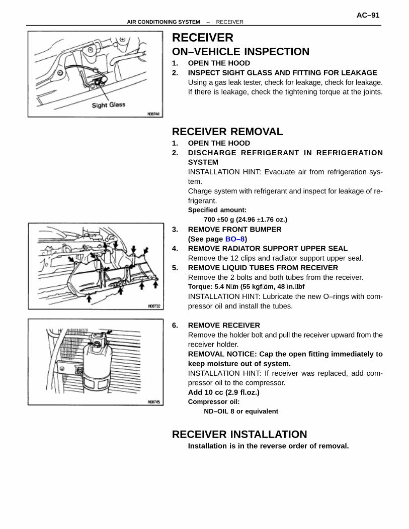
RECEIVERON–VEHICLE INSPECTION1. OPEN THE HOOD2. INSPECT SIGHT GLASS AND FITTING FOR LEAKAGE
Using a gas leak tester, check for leakage, check for leakage.If there is leakage, check the tightening torque at the joints.
RECEIVER REMOVAL1. OPEN THE HOOD2. DISCHARGE REFRIGERANT IN REFRIGERATION
SYSTEMINSTALLATION HINT: Evacuate air from refrigeration sys-tem.Charge system with refrigerant and inspect for leakage of re-frigerant.Specified amount:
700 ±50 g (24.96 ±1.76 oz.)
3. REMOVE FRONT BUMPER(See page BO–8)
4. REMOVE RADIATOR SUPPORT UPPER SEALRemove the 12 clips and radiator support upper seal.
5. REMOVE LIQUID TUBES FROM RECEIVERRemove the 2 bolts and both tubes from the receiver.Torque: 5.4 N ⋅m (55 kgf ⋅cm, 48 in. ⋅lbf
INSTALLATION HINT: Lubricate the new O–rings with com-pressor oil and install the tubes.
6. REMOVE RECEIVERRemove the holder bolt and pull the receiver upward from thereceiver holder.REMOVAL NOTICE: Cap the open fitting immediately tokeep moisture out of system.INSTALLATION HINT: If receiver was replaced, add com-pressor oil to the compressor.Add 10 cc (2.9 fl.oz.)Compressor oil:
ND–OIL 8 or equivalent
RECEIVER INSTALLATIONInstallation is in the reverse order of removal.
–AIR CONDITIONING SYSTEM RECEIVERAC–91

CONDENSERON–VEHICLE INSPECTION1. INSPECT CONDENSER FINS FOR BLO CKAGE OR
DAMAGEIf fins are clogged, wash them with water and dry with com-pressed air.NOTICE: Be careful not to damage the fins.If fins are bent, straighten them with a screwdriver or pliers.
2. INSPECT CONDENSER AND FITTING FOR LEAKAGEUsing a gas leak tester, check for leakage.If there is leakage, check the tightening torque at the joints.
CONDENSER REMOVAL1. DISCHARGE REFRIGERANT IN REFRIGERATION
SYSTEMINSTALLATION HINT: Evacuate air from refrigeration sys-tem.Charge system with refrigerant and inspect for leakage of re-frigerant.Specified amount:
700 ±50g (24.96 ±1.76 oz.)
2. REMOVE BATTERY3. REMOVE AIR CLEANER DUCT
Remove the bolt and the air cleaner duct.
4. REMOVE AIR CLEANER(a) Remove the air cleaner cover.(b) Remove the air cleaner hose.(c) 2JZ–GTE:
Remove the No. 1 air hose.(d) Remove the 3 bolts and 2 screws.(e) Remove the air cleaner.
5. REMOVE NO.5 AIR HOSE CLAMP (2JZ–GTE)(a) Remove the 2 bolts and clamp.(b) Push the hose to engine side.6. REMOVE FRONT BUMPER
(See page BO–88)7. REMOVE RADIATOR SUPPORT UPPER SEAL
(See page AC–91)8. REMOVE RECEIVER
(See page AC–91)
AC–92–AIR CONDITIONING SYSTEM CONDENSER

9. REMOVE LIQUID TUBE AND DISCHARGE TUBETorque: 10 N ⋅m (100 kgf ⋅cm, 7 ft ⋅lbf)
REMOVAL NOTICE: Cap the open fittings immediately tokeep moisture out of the system.INSTALLATION HINT: Lubricate the new O–rings with com-pressor oil and install the tubes.
10. REMOVE CONDENSER(a) Remove the radiator upper mounting.(b) Push the radiator to engine side.
(c) Remove the condenser upper mounting.
(d) Push the condenser to engine side and remove the liquidtube piping clamp.Torque: 4.1 N ⋅m (42 kgf ⋅cm, 36 in. ⋅lbf)
–AIR CONDITIONING SYSTEM CONDENSERAC–93

(e) Push the condenser to engine side and pull it upward.INSTALLATION HINT: If condenser was replaced, add com-pressor oil to the compressor.Add 40 cc (1.4 fl.oz.)Compressor oil:
ND–OIL 8 or equivalent
CONDENSER INSTALLATIONInstallation is in the reverse order of removal.
AC–94–AIR CONDITIONING SYSTEM CONDENSER

EVAPORATOREVAPORATOR REMOVAL1. DISCHARGE REFRIGERANT IN REFRIGERATION
SYSTEMINSTALLATION HINT: Evacuate air from refrigeration sys-tem.Charge system with refrigerant and inspect for leakage of re-frigerant.
2. REMOVE ABS ACTUATOR (w/ABS)(See page BR–44)
3. REMOVE LIQUID TUBE AND SUCTION TUBE FROM A/CUNITTorque: 10 N ⋅m (100 kgf ⋅cm, 7 ft ⋅lbf)
INSTALLATION HINT: Lubricate the new O–rings with com-pressor oil and install the tubes.
4. REMOVE GROVE BOX AND SIDE AIR DUCT(a) Remove the glove box.
(See page BO–45)(b) Remove the 5 screws and the brace.(c) Remove the side air duct.5. REMOVE SCUFF PLATE
(See page BO–44)6. REMOVE FLOOR CARPET
7. REMOVE ECM(a) Remove the 2 nuts and the ECM cover.(b) Remove the 2 nuts and the ECM.
8. REMOVE EVAPORATOR(a) Remove the 6 screws and the lower cover.(b) Remove the 4 screws and the evaporator cover.(c) Remove the evaporator.
INSTALLATION HINT: If evaporator was replaced, add com-pressor oil to the compressor.Add 40 cc (1.4 fl.oz.)Compressor oil
ND–OIL 8 or equivalent
–AIR CONDITIONING SYSTEM EVAPORATORAC–95
EVAPORATOR INSPECTION
1. INSPECT FINS FOR BLOCKAGEIf the fins are clogged, clean them with compressed air.NOTICE: Never use water to clean the evaporator.
2. INSPECT FITTING FOR CRACKS OR SCRATCHESRepair as necessary.
EVAPORATOR INSTALLATIONInstallation is in the reverse order of removal.
HEATER RADIATORHEATER RADIATOR REMOVAL ANDINSTALLATION(See page AC–82)
HEATER RADIATOR INSPECTION
INSPECT FINS FOR BLOCKAGEIf the fins are clogged, clean them with compressed air.
AC–96–AIR CONDITIONING SYSTEM HEATER RADIATOR
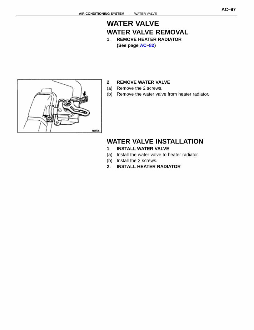
WATER VALVEWATER VALVE REMOVAL1. REMOVE HEATER RADIATOR
(See page AC–82)
2. REMOVE WATER VALVE(a) Remove the 2 screws.(b) Remove the water valve from heater radiator.
WATER VALVE INSTALLATION1. INSTALL WATER VALVE(a) Install the water valve to heater radiator.(b) Install the 2 screws.2. INSTALL HEATER RADIATOR
–AIR CONDITIONING SYSTEM WATER VALVEAC–97

EXPANSION VALVEON–VEHICLE INSPECTION1. CHECK QUANTITY OF GAS DURING REFRIGERATION
CYCLE2. INSTALL MANIFOLD GAUGE SET3. RUN ENGINE
Run the engine at 1,500 rpm for at least 5 minutes. Thencheck that the high pressure reading is 1.371.57 MPa (14–16kgf/cm2, 199–228 psi).
4. CHECK EXPANSION VALVEIf the expansion valve is faulty, the low pressure reading willdrop to 0 kPa (0 kgf/cm2, 0 psi).HINT: When the low pressure drops to 0 kPa (0 kgf/cm2, 0psi), feel the receiver’s IN and OUT sides for zero tempera-ture difference.
EXPANSION VALVE REMOVAL1. REMOVE EVAPORATOR
(See page AC–82)2. REMOVE EXPANSION VALVE
Using a hexagon wrench, remove the 2 bolts and separatethe evaporator and expansion valve.Torque: 5.4 N ⋅m (55 kgf ⋅cm, 48 in. ⋅lbf)INSTALLATION HINT: Lubricate the new O–ring with com-pressor oil and install the tubes.
EXPANSION VALVE INSTALLATIONInstallation is in the reverse order of removal.
AC–98–AIR CONDITIONING SYSTEM EXPANSION VALVE
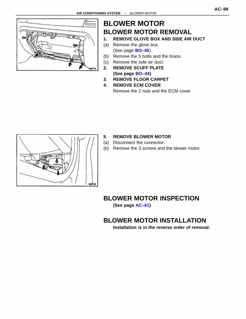
BLOWER MOTORBLOWER MOTOR REMOVAL1. REMOVE GLOVE BOX AND SIDE AIR DUCT(a) Remove the glove box.
(See page BO–45)(b) Remove the 5 bolts and the brace.(c) Remove the side air duct.2. REMOVE SCUFF PLATE
(See page BO–44)3. REMOVE FLOOR CARPET4. REMOVE ECM COVER
Remove the 2 nuts and the ECM cover.
5. REMOVE BLOWER MOTOR(a) Disconnect the connector.(b) Remove the 3 screws and the blower motor.
BLOWER MOTOR INSPECTION(See page AC–61)
BLOWER MOTOR INSTALLATIONInstallation is in the reverse order of removal.
–AIR CONDITIONING SYSTEM BLOWER MOTORAC–99

BLOWER MOTOR CONTROL RELAYBLOWER MOTOR CONTROL RELAYREMOVAL1. REMOVE BLOWER MOTOR
(See page AC–82)
2. REMOVE BLOWER MOTOR CONTROL RELAY(a) Disconnect the connector.(b) Remove the 3 screws and the blower motor control relay.
BLOWER MOTOR CONTROL RELAYINSPECTION(See page AC–61)
BLOWER MOTOR CONTROL RELAYINSTALLATION
Installation is in the reverse order of removal.
AC–100–AIR CONDITIONING SYSTEM BLOWER MOTOR CONTROL RELAY

SERVOMOTORAIR INLET SERVOMOTOR REMOVAL1. REMOVE INSTRUMENT PANEL
(See page BO–45)2. REMOVE AIR INLET SERVOMOTOR(a) Disconnect the connector.(b) Disconnect the control link.(c) Remove the 3 screws and the air inlet servomotor.
AIR INLET SERVOMOTOR INSPECTION(See page AC–47)
AIR INLET SERVOMOTORINSTALLATION
Installation is in the reverse order of removal.
AIR MIX SERVOMOTOR REMOVAL1. REMOVE INSTRUMENT PANEL
(See page BO–45)2. REMOVE AIR MIX SERVOMOTOR(a) Remove the defroster duct.(b) Remove the 3 screws and the water valve cover.(c) Disconnect the connector.
(d) Disconnect the control link.(e) Remove the 2 screws and the air mix servomotor.
AIR MIX SERVOMOTOR INSPECTION(See page AC–47)
AIR MIX SERVOMOTOR INSTALLATIONInstallation is in the reverse order of removal.
–AIR CONDITIONING SYSTEM SERVOMOTORAC–101
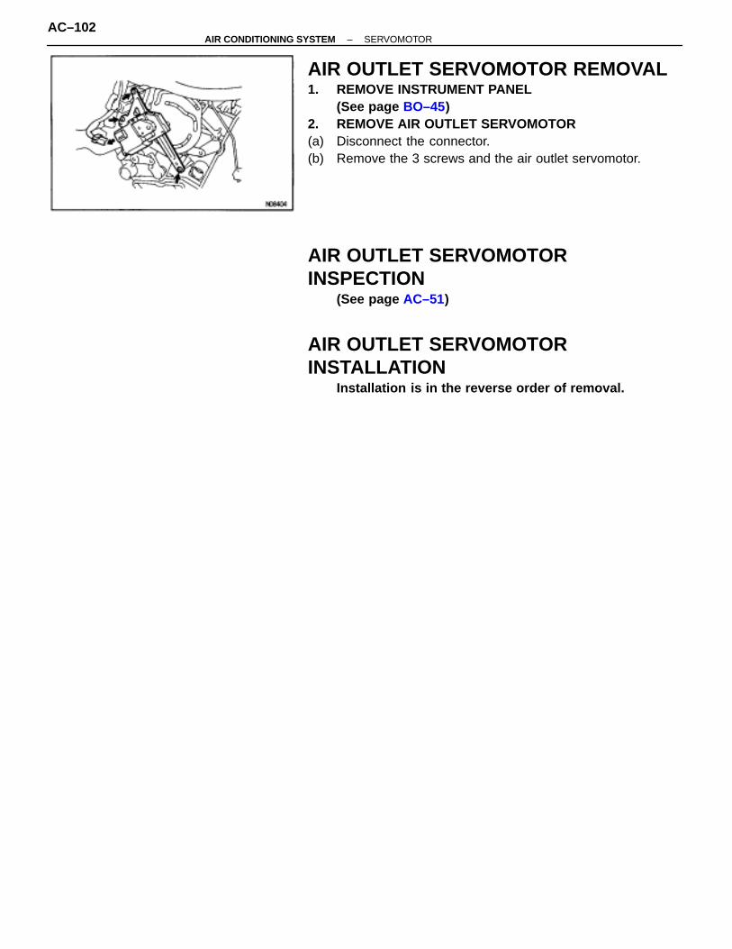
AIR OUTLET SERVOMOTOR REMOVAL1. REMOVE INSTRUMENT PANEL
(See page BO–45)2. REMOVE AIR OUTLET SERVOMOTOR(a) Disconnect the connector.(b) Remove the 3 screws and the air outlet servomotor.
AIR OUTLET SERVOMOTORINSPECTION
(See page AC–51)
AIR OUTLET SERVOMOTORINSTALLATION
Installation is in the reverse order of removal.
AC–102–AIR CONDITIONING SYSTEM SERVOMOTOR
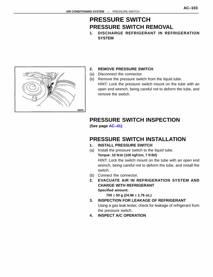
PRESSURE SWITCHPRESSURE SWITCH REMOVAL1. DISCHARGE REFRIGERANT IN REFRIGERATION
SYSTEM
2. REMOVE PRESSURE SWITCH(a) Disconnect the connector.(b) Remove the pressure switch from the liquid tube.
HINT: Lock the pressure switch mount on the tube with anopen end wrench, being careful not to deform the tube, andremove the switch.
PRESSURE SWITCH INSPECTION(See page AC–41)
PRESSURE SWITCH INSTALLATION1. INSTALL PRESSURE SWITCH(a) Install the pressure switch to the liquid tube.
Torque: 10 N ⋅m (100 kgf ⋅cm, 7 ft ⋅lbf)
HINT: Lock the switch mount on the tube with an open endwrench, being careful not to deform the tube, and install theswitch.
(b) Connect the connector.2. EVACUATE AIR IN REFRIGERATION SYSTEM AND
CHARGE WITH REFRIGERANTSpecified amount:
700 ± 50 g (24.96 ± 1.76 oz.)
3. INSPECTION FOR LEAKAGE OF REFRIGERANTUsing a gas leak tester, check for leakage of refrigerant fromthe pressure switch.
4. INSPECT A/C OPERATION
–AIR CONDITIONING SYSTEM PRESSURE SWITCHAC–103
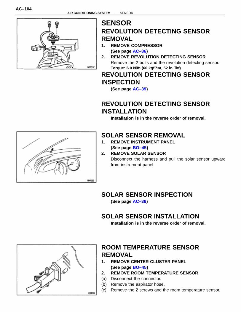
SENSORREVOLUTION DETECTING SENSORREMOVAL1. REMOVE COMPRESSOR
(See page AC–86)2. REMOVE REVOLUTION DETECTING SENSOR
Remove the 2 bolts and the revolution detecting sensor.Torque: 6.0 N ⋅m (60 kgf ⋅cm, 52 in. ⋅lbf)
REVOLUTION DETECTING SENSORINSPECTION
(See page AC–39)
REVOLUTION DETECTING SENSORINSTALLATION
Installation is in the reverse order of removal.
SOLAR SENSOR REMOVAL1. REMOVE INSTRUMENT PANEL
(See page BO–45)2. REMOVE SOLAR SENSOR
Disconnect the harness and pull the solar sensor upwardfrom instrument panel.
SOLAR SENSOR INSPECTION(See page AC–36)
SOLAR SENSOR INSTALLATIONInstallation is in the reverse order of removal.
ROOM TEMPERATURE SENSORREMOVAL1. REMOVE CENTER CLUSTER PANEL
(See page BO–45)2. REMOVE ROOM TEMPERATURE SENSOR(a) Disconnect the connector.(b) Remove the aspirator hose.(c) Remove the 2 screws and the room temperature sensor.
AC–104–AIR CONDITIONING SYSTEM SENSOR

ROOM TEMPERATURE SENSORINSPECTION
(See page AC–28)
ROOM TEMPERATURE SENSORINSTALLATION
Installation is in the reverse of removal.
EVAPORATOR TEMPERATURE SENSORREMOVAL1. REMOVE EVAPORATOR
(See page AC–82)2. REMOVE EVAPORATOR TEMPERATURE SENSOR
Pull out the evaporator temperature sensor from the evapo-rator.
EVAPORATOR TEMPERATURE SENSORINSPECTION(See page AC–32)
EVAPORATOR TEMPERATURE SENSORINSTALLATION
Installation is in the reverse order of removal.
AMBIENT TEMPERATURE SENSORREMOVAL
REMOVE AMBIENT TEMPERATURE SENSOR(a) Remove the ambient temperature sensor from the bumper
reinforcement.(b) Disconnect the connector.
AMBIENT TEMPERATURE SENSORINSPECTION(See page AC–30)
AMBIENT TEMPERATURE SENSORINSTALLATION
Installation is in the reverse order of removal.
–AIR CONDITIONING SYSTEM SENSORAC–105

ENGINE COOLANT TEMPERATURESENSOR REMOVAL1. REMOVE AIR CONDITIONING UNIT
(See page AC–80)
2. REMOVE ENGINE COOLANT TEMPERATURE SENSOR(a) Disconnect the connector.(b) After pulling off the clamp, pull out the sensor.
ENGINE COOLANT TEMPERATURESENSOR INSPECTION(See page AC–34)
ENGINE COOLANT TEMPERATURESENSOR INSTALLATION
Installation is in the reverse order of removal.
AC–106–AIR CONDITIONING SYSTEM SENSOR

ELECTRIC COOLING FANON–VEHICLE INSPECTIONCondenser Fan:1. INSPECT CONDENCER(a) Disconnect the fan connector.(b) Connect battery and ammeter to the cooling fan connector.(c) Check that the condenser fan rotates smoothly, and check
the reading on the ammeter.Standard amperage:
6.0–7.4 A
(d) Reconect the fan connector.2. CONNECT NEGATIVE (–) TERMINAL CABLE TO
BATTERY
Radiator Fan:(See page EG–353)
COOLING FAN RELAYS INSPECTION(See page EG–356)
ECT SWITCH(in ENGINE RADIATOR)
(See page EG–356)
–AIR CONDITIONING SYSTEM ELECTRIC COOLING FANAC–107

RELAYHEATER MAIN RELAYHEATER MAIN RELAY REMOVAL1. REMOVE JUNCTION BLOCK NO. 2 COVER
Remove the 2 clips and the junction block No. 2 cover.2. REMOVE HEATER MAIN RELAY
HEATER MAIN RELAY INSPECTION(See page AC–59)
HEATER MAIN RELAY INSTALLATIONInstallation is in the reverse order of removal.
MAGNETIC CLUTCH RELAYMAGNETIC CLUTCH RELAY REMOVAL1. REMOVE JUNCTION BLOCK NO. 2 COVER
Remove the 2 clips and the junction block No. 2 cover.2. REMOVE MAGNETIC CLUTCH RELAY
MAGNETIC CLUTCH RELAYINSPECTION(See page AC–65)
MAGNETIC CLUTCH RELAYINSTALLATION
Installation is in the reverse order of removal.
AC–108–AIR CONDITIONING SYSTEM RELAY

AIR CONDITIONING AMPLIFIERAIR CONDITIONING AMPLIFIERREMOVAL1. REMOVE CENTER CLUSTER PANEL
(See page BO–45)2. REMOVE RADIO WITH AIR CONDITIONING AMPLIFIER(a) Remove the 4 screws and radio with the air conditioning
amplifier.(b) Disconnect the connectors.3. REMOVE AIR CONDITIONING AMPLIFIER FROM RADIO(a) Remove the 4 screws and the 4 bolts.(b) Remove the air conditioning amplifier from radio.
AIR CONDITIONING AMPLIFIERINSPECTION
(See page AC–23)
AIR CONDITIONING AMPLIFIERINSTALLATION
Installation is in the reverse order of removal.
–AIR CONDITIONING SYSTEM AIR CONDITIONING AMPLIFIERAC–109

AIR CONDITIONING CONTROLASSEMBLYAIR CONDITIONING CONTROLASSEMBLY REMOVAL1. REMOVE CENTER CLUSTER PANEL
(See page BO–45)2. REMOVE AIR CONDITIONING CONTROL ASSEMBLY(a) Disconnect the connector.(b) Remove the 3 screws and the air conditioning control
assembly.
AIR CONDITIONING CONTROLASSEMBLY INSPECTION(See page AC–66)
AIR CONDITIONING CONTROLASSEMBLY INSTALLATION
Installation is in the reverse order of removal.
AC–110–AIR CONDITIONING SYSTEM AIR CONDITIONING CONTROL ASSEMBLY

SERVICE SPECIFICATIONSSERVICE DATAÑÑÑÑÑÑÑÑÑÑÑÑÑÑÑÑÑÑÑÑÑÑÑÑÑÑÑÑÑÑÑÑÑÑÑÑ
Refrigerant charge volume ÑÑÑÑÑÑÑÑÑÑÑÑÑÑÑÑÑÑÑÑÑÑÑÑÑÑÑÑÑÑÑÑÑÑÑÑÑÑ
700 ± 50g. 24.96 ± 1.76 oz.
ÑÑÑÑÑÑÑÑÑÑÑÑÑÑÑÑÑÑÑÑÑÑÑÑÑÑÑÑÑÑÑÑÑÑÑÑ
Idle speed ÑÑÑÑÑÑÑÑÑÑÑÑÑÑÑÑÑÑÑÑÑÑÑÑÑÑÑÑÑÑÑÑÑÑÑÑÑÑÑÑÑÑÑÑÑÑÑÑÑÑÑÑÑÑÑÑ
ÑÑÑÑÑÑÑÑÑÑÑÑÑÑÑÑÑÑ2JZ–GE (M/T)
ÑÑÑÑÑÑÑÑÑÑÑÑÑÑÑÑÑÑÑÑÑÑÑÑÑÑÑÑÑÑÑÑÑÑÑÑÑÑÑÑÑÑÑÑÑÑÑÑÑÑÑÑÑÑÑÑ
ÑÑÑÑÑÑÑÑÑÑÑÑÑÑÑÑÑÑÑÑÑÑÑÑÑÑÑÑÑÑÑÑÑÑÑÑ
Magnetic clutch not engagedÑÑÑÑÑÑÑÑÑÑÑÑÑÑÑÑÑÑÑÑÑÑÑÑÑÑÑÑÑÑÑÑÑÑÑÑÑÑÑÑÑÑÑÑÑÑÑÑÑÑÑÑÑÑÑÑÑ
Approx. 700 rpm
ÑÑÑÑÑÑÑÑÑÑÑÑÑÑÑÑÑÑÑÑÑÑÑÑÑÑÑÑÑÑÑÑÑÑÑÑ
Magnetic clutch engaged ÑÑÑÑÑÑÑÑÑÑÑÑÑÑÑÑÑÑÑÑÑÑÑÑÑÑÑÑÑÑÑÑÑÑÑÑÑÑ
Approx. 900 rpm
ÑÑÑÑÑÑÑÑÑÑÑÑÑÑÑÑÑÑÑÑÑÑÑÑÑÑÑÑÑÑÑÑÑÑÑÑ
2JZ–GE (A/T) ÑÑÑÑÑÑÑÑÑÑÑÑÑÑÑÑÑÑÑÑÑÑÑÑÑÑÑÑÑÑÑÑÑÑÑÑÑÑÑÑÑÑÑÑÑÑÑÑÑÑÑÑÑÑÑÑ
ÑÑÑÑÑÑÑÑÑÑÑÑÑÑÑÑÑÑÑÑÑÑÑÑÑÑÑÑÑÑÑÑÑÑÑÑ
Magnetic clutch not engagedÑÑÑÑÑÑÑÑÑÑÑÑÑÑÑÑÑÑÑÑÑÑÑÑÑÑÑÑÑÑÑÑÑÑÑÑÑÑÑÑÑÑÑÑÑÑÑÑÑÑÑÑÑÑÑÑÑ
Approx. 700 rpm
ÑÑÑÑÑÑÑÑÑÑÑÑÑÑÑÑÑÑÑÑÑÑÑÑÑÑÑÑÑÑÑÑÑÑÑÑ
Magnetic clutch engaged ÑÑÑÑÑÑÑÑÑÑÑÑÑÑÑÑÑÑÑÑÑÑÑÑÑÑÑÑÑÑÑÑÑÑÑÑÑÑ
Approx. 800 rpm
ÑÑÑÑÑÑÑÑÑÑÑÑÑÑÑÑÑÑÑÑÑÑÑÑÑÑÑÑÑÑÑÑÑÑÑÑ
2JZ–GTE ÑÑÑÑÑÑÑÑÑÑÑÑÑÑÑÑÑÑÑÑÑÑÑÑÑÑÑÑÑÑÑÑÑÑÑÑÑÑÑÑÑÑÑÑÑÑÑÑÑÑÑÑÑÑÑÑ
ÑÑÑÑÑÑÑÑÑÑÑÑÑÑÑÑÑÑ Magnetic clutch not engaged
ÑÑÑÑÑÑÑÑÑÑÑÑÑÑÑÑÑÑÑÑÑÑÑÑÑÑÑÑÑÑÑÑÑÑÑÑÑÑ
Approx. 650 rpmÑÑÑÑÑÑÑÑÑÑÑÑÑÑÑÑÑÑÑÑÑÑÑÑÑÑÑÑÑÑÑÑÑÑÑÑÑÑÑÑÑÑÑÑÑÑÑÑÑÑÑÑÑÑ
Magnetic clutch engagedÑÑÑÑÑÑÑÑÑÑÑÑÑÑÑÑÑÑÑÑÑÑÑÑÑÑÑÑÑÑÑÑÑÑÑÑÑÑÑÑÑÑÑÑÑÑÑÑÑÑÑÑÑÑÑÑÑ
Approx. 800 rpm
TORQUE SPECIFICATIONSÑÑÑÑÑÑÑÑÑÑÑÑÑÑÑÑÑÑÑÑÑÑÑÑÑÑÑÑÑÑÑÑÑÑÑÑÑÑÑÑÑÑÑÑÑÑÑÑÑÑÑÑÑÑÑÑÑÑÑÑÑÑÑÑÑÑÑÑÑ
Part tightenedÑÑÑÑÑÑÑÑÑÑÑÑÑÑÑ
N⋅mÑÑÑÑÑÑÑÑÑÑÑÑÑÑÑ
kgf ⋅cmÑÑÑÑÑÑÑÑÑÑÑÑÑÑÑÑÑÑ
ft ⋅lbf
ÑÑÑÑÑÑÑÑÑÑÑÑÑÑÑÑÑÑÑÑÑÑÑÑÑÑÑÑÑÑÑÑÑÑÑÑÑÑÑÑÑÑÑÑÑÑ
Suction hose x Compressor ÑÑÑÑÑÑÑÑÑÑ
10 ÑÑÑÑÑÑÑÑÑÑ
100 ÑÑÑÑÑÑÑÑÑÑÑÑ
7
ÑÑÑÑÑÑÑÑÑÑÑÑÑÑÑÑÑÑÑÑÑÑÑÑÑÑÑÑÑÑÑÑÑÑÑÑÑÑÑÑÑÑÑÑÑÑ
Discharge hose x Compressor ÑÑÑÑÑÑÑÑÑÑ
10 ÑÑÑÑÑÑÑÑÑÑ
100 ÑÑÑÑÑÑÑÑÑÑÑÑ
7ÑÑÑÑÑÑÑÑÑÑÑÑÑÑÑÑÑÑÑÑÑÑÑÑÑÑÑÑÑÑÑÑÑÑÑÑÑÑÑÑÑÑÑÑÑÑ
Compressor x Engine Stud boltÑÑÑÑÑÑÑÑÑÑ
26ÑÑÑÑÑÑÑÑÑÑ
265ÑÑÑÑÑÑÑÑÑÑÑÑ
19.2ÑÑÑÑÑÑÑÑÑÑÑÑÑÑÑÑÑÑÑÑÑÑÑÑÑÑÑÑÑÑÑÑÑÑÑÑÑÑÑÑÑÑÑÑÑÑÑÑÑÑÑÑÑÑÑÑÑÑÑÑÑÑÑÑÑÑÑÑÑ
Other bolts and nutÑÑÑÑÑÑÑÑÑÑÑÑÑÑÑ
52ÑÑÑÑÑÑÑÑÑÑÑÑÑÑÑ
530ÑÑÑÑÑÑÑÑÑÑÑÑÑÑÑÑÑÑ
38.3
ÑÑÑÑÑÑÑÑÑÑÑÑÑÑÑÑÑÑÑÑÑÑÑÑÑÑÑÑÑÑÑÑÑÑÑÑÑÑÑÑÑÑÑÑÑÑ
Liquid tube x Receiver ÑÑÑÑÑÑÑÑÑÑ
5.4 ÑÑÑÑÑÑÑÑÑÑ
55 ÑÑÑÑÑÑÑÑÑÑÑÑ
48 in.⋅lbf
ÑÑÑÑÑÑÑÑÑÑÑÑÑÑÑÑÑÑÑÑÑÑÑÑÑÑÑÑÑÑÑÑÑÑÑÑÑÑÑÑÑÑÑÑÑÑ
Liquid tube x Condenser ÑÑÑÑÑÑÑÑÑÑ
10 ÑÑÑÑÑÑÑÑÑÑ
100 ÑÑÑÑÑÑÑÑÑÑÑÑ
7ÑÑÑÑÑÑÑÑÑÑÑÑÑÑÑÑÑÑÑÑÑÑÑÑÑÑÑÑÑÑÑÑÑÑÑÑÑÑÑÑÑÑÑÑÑÑÑÑÑÑÑÑÑÑÑÑÑÑÑÑÑÑÑÑÑÑÑÑÑ
Discharge tube x CondenserÑÑÑÑÑÑÑÑÑÑÑÑÑÑÑ
10ÑÑÑÑÑÑÑÑÑÑÑÑÑÑÑ
100ÑÑÑÑÑÑÑÑÑÑÑÑÑÑÑÑÑÑ
7
ÑÑÑÑÑÑÑÑÑÑÑÑÑÑÑÑÑÑÑÑÑÑÑÑÑÑÑÑÑÑÑÑÑÑÑÑÑÑÑÑÑÑÑÑÑÑ
Expansion valve x Evaporator ÑÑÑÑÑÑÑÑÑÑ
5.4 ÑÑÑÑÑÑÑÑÑÑ
55 ÑÑÑÑÑÑÑÑÑÑÑÑ
48 in.⋅lbf
ÑÑÑÑÑÑÑÑÑÑÑÑÑÑÑÑÑÑÑÑÑÑÑÑÑÑÑÑÑÑÑÑÑÑÑÑÑÑÑÑÑÑÑÑÑÑ
Suction tube x A/C unit ÑÑÑÑÑÑÑÑÑÑ
10 ÑÑÑÑÑÑÑÑÑÑ
100 ÑÑÑÑÑÑÑÑÑÑÑÑ
7ÑÑÑÑÑÑÑÑÑÑÑÑÑÑÑÑÑÑÑÑÑÑÑÑÑÑÑÑÑÑÑÑÑÑÑÑÑÑÑÑÑÑÑÑÑÑ
Liquid tube x A/C unitÑÑÑÑÑÑÑÑÑÑ
10ÑÑÑÑÑÑÑÑÑÑ
100ÑÑÑÑÑÑÑÑÑÑÑÑ
7ÑÑÑÑÑÑÑÑÑÑÑÑÑÑÑÑÑÑÑÑÑÑÑÑÑÑÑÑÑÑÑÑÑÑÑÑÑÑÑÑÑÑÑÑÑÑÑÑÑÑÑÑÑÑÑÑÑÑÑÑÑÑÑÑÑÑÑÑÑ
Pressure switch x Liquired tubeÑÑÑÑÑÑÑÑÑÑÑÑÑÑÑ
10ÑÑÑÑÑÑÑÑÑÑÑÑÑÑÑ
100ÑÑÑÑÑÑÑÑÑÑÑÑÑÑÑÑÑÑ
7
ÑÑÑÑÑÑÑÑÑÑÑÑÑÑÑÑÑÑÑÑÑÑÑÑÑÑÑÑÑÑÑÑÑÑÑÑÑÑÑÑÑÑÑÑÑÑ
Revolution detecting sensor x Compressor ÑÑÑÑÑÑÑÑÑÑ
6.0 ÑÑÑÑÑÑÑÑÑÑ
60 ÑÑÑÑÑÑÑÑÑÑÑÑ
52 in.⋅lbf
ÑÑÑÑÑÑÑÑÑÑÑÑÑÑÑÑÑÑÑÑÑÑÑÑÑÑÑÑÑÑÑÑÑÑÑÑÑÑÑÑÑÑÑÑÑÑ
Condenser upper mounting x Body ÑÑÑÑÑÑÑÑÑÑ
4.1 ÑÑÑÑÑÑÑÑÑÑ
42 ÑÑÑÑÑÑÑÑÑÑÑÑ
36 in.⋅lbfÑÑÑÑÑÑÑÑÑÑÑÑÑÑÑÑÑÑÑÑÑÑÑÑÑÑÑÑÑÑÑÑÑÑÑÑÑÑÑÑÑÑÑÑÑÑÑÑÑÑÑÑÑÑÑÑÑÑÑÑÑÑÑÑÑÑÑÑÑ
Liquid linesÑÑÑÑÑÑÑÑÑÑÑÑÑÑÑ
10ÑÑÑÑÑÑÑÑÑÑÑÑÑÑÑ
100ÑÑÑÑÑÑÑÑÑÑÑÑÑÑÑÑÑÑ
7
ÑÑÑÑÑÑÑÑÑÑÑÑÑÑÑÑÑÑÑÑÑÑÑÑÑÑÑÑÑÑÑÑÑÑÑÑÑÑÑÑÑÑÑÑÑÑ
Discharge lines ÑÑÑÑÑÑÑÑÑÑ
10 ÑÑÑÑÑÑÑÑÑÑ
100 ÑÑÑÑÑÑÑÑÑÑÑÑ
7
ÑÑÑÑÑÑÑÑÑÑÑÑÑÑÑÑÑÑÑÑÑÑÑÑÑÑÑÑÑÑÑÑÑÑÑÑÑÑÑÑÑÑÑÑÑÑ
Suction lines ÑÑÑÑÑÑÑÑÑÑ
10 ÑÑÑÑÑÑÑÑÑÑ
100 ÑÑÑÑÑÑÑÑÑÑÑÑ
7
–AIR CONDITIONING SYSTEM SERVICE SPECIFICATIONSAC–111