air cooled packaged air conditioners · 2019-01-28 · * air introduced from the outside and...
TRANSCRIPT
AIR COOLED PACKAGEDAIR CONDITIONERS
APCVDT1502A
FLOOR STANDING TYPE
COOLING ONLY 50Hz
FLOOR STANDING TYPE
DUCT CONNECTION TYPE
Nice, cool air in the factory or in the cafeteria
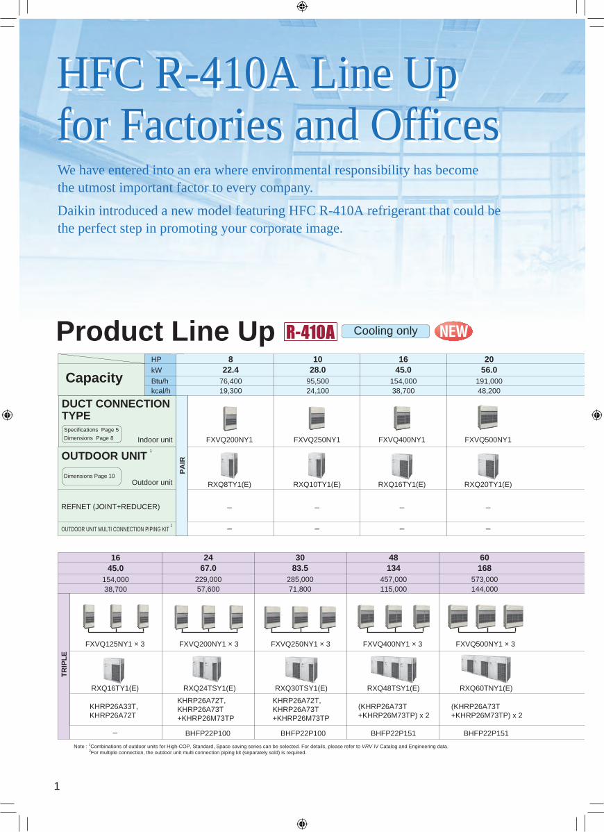
HFC R-410A Line Upfor Factories and OfficesHFC R-410A Line Upfor Factories and Offices
Cooling only
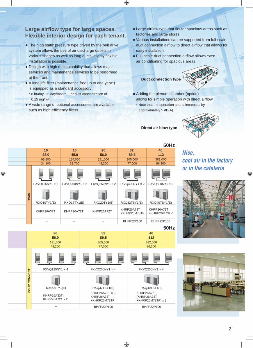
Large airflow type that fits for spacious areas such as factories and large stores. Various installations can be supported from full-scale duct connection airflow to direct airflow that allows for easy installation. Full-scale duct connection airflow allows even air conditioning for spacious areas.
Adding the plenum chamber (option) allows for simple operation with direct airflow. * Note that the operation sound increases by
approximately 5 dB(A).
Large airflow type for large spaces.Flexible interior design for each tenant.
The high static pressure type driven by the belt drive system allows the use of air discharge outlets in various shapes as well as long ducts. Highly flexible installation is possible. Design with high maintainability that allows major services and maintenance services to be performed at the front. A long-life filter (maintenance free up to one year*) is equipped as a standard accessory. * 8 hr/day, 26 day/month. For dust concentration of
0.15 mg/m3
A wide range of optional accessories are available such as high-efficiency filters.
Duct connection type
Direct air blow type
We have entered into an era where environmental responsibility has become the utmost important factor to every company.
Daikin introduced a new model featuring HFC R-410A refrigerant that could be the perfect step in promoting your corporate image.
FXVQ125NY1 × 4 FXVQ200NY1 × 4 FXVQ250NY1 × 4FXVQ500NY1 × 3FXVQ400NY1 × 3FXVQ125NY1 × 3 FXVQ200NY1 × 3 FXVQ250NY1 × 3
Indoor unit FXVQ400NY1FXVQ200NY1 FXVQ250NY1 FXVQ500NY1
DUCT CONNECTION TYPESpecifications Page 5
Dimensions Page 8 FXVQ125NY1 × 2 FXVQ200NY1 × 2 FXVQ250NY1 × 2 FXVQ400NY1 × 2 FXVQ500NY1 × 2
Product Line Up50Hz
76,400
22.495,500
28.0191,000
56.0154,000
45.0154,000
45.095,500
28.0191,000
56.0305,000
19,300 24,100 48,20038,700 38,70024,100 48,200 77,000
89.5382,00096,300
1128 20 10 201610 16 32
kWCapacity
Btu/hkcal/h
HP
OUTDOOR UNIT 1
Note : 1Combinations of outdoor units for High-COP, Standard, Space saving series can be selected. For details, please refer to VRV IV Catalog and Engineering data.2For multiple connection, the outdoor unit multi connection piping kit (separately sold) is required.
Dimensions Page 10
50Hz
229,000
67.0285,000
83.5573,000
168191,000
56.0457,000
13424 60 204830
57,600 71,800 144,000115,000 48,200305,000
89.532
77,000382,000
11240
96,300
Outdoor unit
REFNET (JOINT+REDUCER)
OUTDOOR UNIT MULTI CONNECTION PIPING KIT 2
PA
IR
40
TR
IPL
E
154,000
45.0
38,700
16
FO
UR
CO
NN
EC
TT
WIN
TR
IPL
E
RXQ8TY1(E)
KHRP26A73T+KHRP26M73TP
KHRP26A72TKHRP26A72TKHRP26A33T
KHRP26A33T,KHRP26A72T
KHRP26A33T,KHRP26A72T x 2
KHRP26A72T,KHRP26A73T+KHRP26M73TP
KHRP26A72T,KHRP26A73T+KHRP26M73TP
(KHRP26A73T+KHRP26M73TP) x 2
(KHRP26A73T+KHRP26M73TP) x 2
KHRP26A72T × 2,KHRP26A73T+KHRP26M73TP
KHRP26A72T,(KHRP26A73T+KHRP26M73TP) x 2
KHRP26A73T+KHRP26M73TP– – – –
–
– –
– – – – – –
RXQ16TY1(E) RXQ24TSY1(E) RXQ30TSY1(E) RXQ48TSY1(E) RXQ60TNY1(E) RXQ20TY1(E) RXQ32TSY1(E) RXQ40TSY1(E)
RXQ10TY1(E) RXQ16TY1(E) RXQ20TY1(E) RXQ10TY1(E) RXQ16TY1(E)
BHFP22P100
BHFP22P100 BHFP22P100 BHFP22P100 BHFP22P100BHFP22P151 BHFP22P151
BHFP22P100
RXQ20TY1(E) RXQ32TSY1(E) RXQ40TSY1(E)
1
Nice, cool air in the factory or in the cafeteria
HFC R-410A Line Upfor Factories and OfficesHFC R-410A Line Upfor Factories and Offices
Cooling only
Large airflow type that fits for spacious areas such as factories and large stores. Various installations can be supported from full-scale duct connection airflow to direct airflow that allows for easy installation. Full-scale duct connection airflow allows even air conditioning for spacious areas.
Adding the plenum chamber (option) allows for simple operation with direct airflow. * Note that the operation sound increases by
approximately 5 dB(A).
Large airflow type for large spaces.Flexible interior design for each tenant.
The high static pressure type driven by the belt drive system allows the use of air discharge outlets in various shapes as well as long ducts. Highly flexible installation is possible. Design with high maintainability that allows major services and maintenance services to be performed at the front. A long-life filter (maintenance free up to one year*) is equipped as a standard accessory. * 8 hr/day, 26 day/month. For dust concentration of
0.15 mg/m3
A wide range of optional accessories are available such as high-efficiency filters.
Duct connection type
Direct air blow type
We have entered into an era where environmental responsibility has become the utmost important factor to every company.
Daikin introduced a new model featuring HFC R-410A refrigerant that could be the perfect step in promoting your corporate image.
FXVQ125NY1 × 4 FXVQ200NY1 × 4 FXVQ250NY1 × 4FXVQ500NY1 × 3FXVQ400NY1 × 3FXVQ125NY1 × 3 FXVQ200NY1 × 3 FXVQ250NY1 × 3
Indoor unit FXVQ400NY1FXVQ200NY1 FXVQ250NY1 FXVQ500NY1
DUCT CONNECTION TYPESpecifications Page 5
Dimensions Page 8 FXVQ125NY1 × 2 FXVQ200NY1 × 2 FXVQ250NY1 × 2 FXVQ400NY1 × 2 FXVQ500NY1 × 2
Product Line Up50Hz
76,400
22.495,500
28.0191,000
56.0154,000
45.0154,000
45.095,500
28.0191,000
56.0305,000
19,300 24,100 48,20038,700 38,70024,100 48,200 77,000
89.5382,00096,300
1128 20 10 201610 16 32
kWCapacity
Btu/hkcal/h
HP
OUTDOOR UNIT 1
Note : 1Combinations of outdoor units for High-COP, Standard, Space saving series can be selected. For details, please refer to VRV IV Catalog and Engineering data.2For multiple connection, the outdoor unit multi connection piping kit (separately sold) is required.
Dimensions Page 10
50Hz
229,000
67.0285,000
83.5573,000
168191,000
56.0457,000
13424 60 204830
57,600 71,800 144,000115,000 48,200305,000
89.532
77,000382,000
11240
96,300
Outdoor unit
REFNET (JOINT+REDUCER)
OUTDOOR UNIT MULTI CONNECTION PIPING KIT 2
PA
IR
40
TR
IPL
E
154,000
45.0
38,700
16
FO
UR
CO
NN
EC
TT
WIN
TR
IPL
E
RXQ8TY1(E)
KHRP26A73T+KHRP26M73TP
KHRP26A72TKHRP26A72TKHRP26A33T
KHRP26A33T,KHRP26A72T
KHRP26A33T,KHRP26A72T x 2
KHRP26A72T,KHRP26A73T+KHRP26M73TP
KHRP26A72T,KHRP26A73T+KHRP26M73TP
(KHRP26A73T+KHRP26M73TP) x 2
(KHRP26A73T+KHRP26M73TP) x 2
KHRP26A72T × 2,KHRP26A73T+KHRP26M73TP
KHRP26A72T,(KHRP26A73T+KHRP26M73TP) x 2
KHRP26A73T+KHRP26M73TP– – – –
–
– –
– – – – – –
RXQ16TY1(E) RXQ24TSY1(E) RXQ30TSY1(E) RXQ48TSY1(E) RXQ60TNY1(E) RXQ20TY1(E) RXQ32TSY1(E) RXQ40TSY1(E)
RXQ10TY1(E) RXQ16TY1(E) RXQ20TY1(E) RXQ10TY1(E) RXQ16TY1(E)
BHFP22P100
BHFP22P100 BHFP22P100 BHFP22P100 BHFP22P100BHFP22P151 BHFP22P151
BHFP22P100
RXQ20TY1(E) RXQ32TSY1(E) RXQ40TSY1(E)
2
FLOOR STANDING TYPE
DUCT CONNECTION TYPE
AIR COOLED PACKAGED AIR CONDITIONERS
RXQ20TY1(E)
FXVQ500NY1
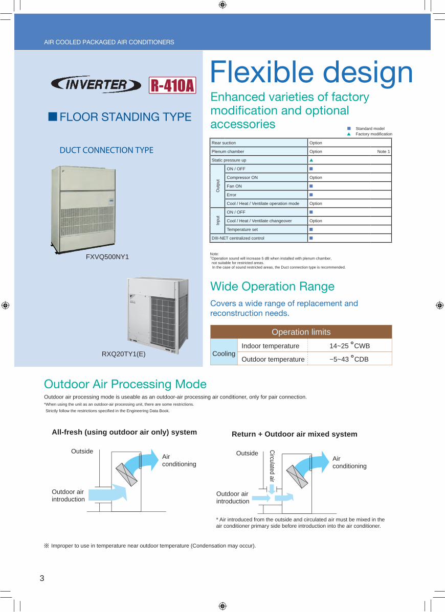
Enhanced varieties of factory modication and optional accessories
Note: 1Operation sound will increase 5 dB when installed with plenum chamber, not suitable for restricted areas. In the case of sound restricted areas, the Duct connection type is recommended.
Covers a wide range of replacement and reconstruction needs.
Wide Operation Range
Outdoor Air Processing Mode
Flexible design and high energy saving
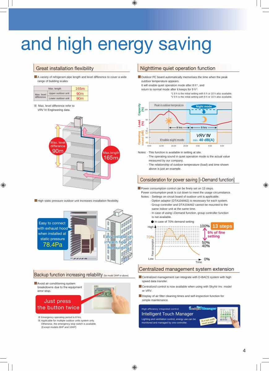
A variety of refrigerant pipe length and level difference to cover a wide range of building scales
Great installation exibility
Max. length
Upper outdoor unit
Lower outdoor unit
90m165m
Max.length
165
Max. leveldifference
90m
90m
High static pressure outdoor unit increases installation flexibility.
Easy installation in each oor of
the building
Easy installation in each oor of
the building
Easy to connect with exhaust hoodwhen installed at
static pressure 78.4Pa
Max. level difference
Nighttime quiet operation function
Consideration for power saving [i-Demand function]
Centralized management can integrate with D-BACS system with high speed data transfer.
Centralized control is now available when using with SkyAir Inv. model or VRV.
Display of air filter cleaning times and self-inspection function for simple maintenance.
Centralized management system extension
Avoid air conditioning system breakdowns due to the equipment error stop.
Emergency operating period is 8 hrs. Applicable for multiple outdoor units system only.
Otherwise, the emergency stop switch is available. (Except models 8HP and 10HP)
Backup function increasing reliability (for model 24HP or above)
Just press the button twice
Outdoor PC board automatically memorises the time when the peak outdoor temperature appears. It will enable quiet operation mode after 8 h*1, and return to normal mode after it keeps for 9 h*2.
*1 8 h is the initial setting with 6 h or 10 h also available.*2 9 h is the initial setting with 8 h or 10 h also available.
Notes: · This function is available in setting at site. · The operating sound in quiet operation mode is the actual value measured by our company. · The relationship of outdoor temperature (load) and time shown above is just an example.
Peak in outdoor temperaturePeak in outdoor temperaturePeak in outdoor temperature
Enable night mode Enable night mode Enable night mode
Op
erat
ing
so
un
d (
dB
)L
oad
(%
)C
apac
ity
(%) Night mode
min. 40 dB(A)
8 hrs
8:00
50
60
50
100
0
40
57
12:00 16:00 20:00 0:00 4:00 8:00
9 hrs
VRV IVVRV IV
Power consumption control can be finely set on 13 steps. Power consumption peak is cut down to meet the usage circumstance. Notes: · Settings on circuit board of outdoor unit is applicable. · Option adaptor (DTA104A62) is necessary for each system. · Group controller and DTA104A62 cannot be mounted to the same indoor unit at the same time. · In case of using i-Demand function, group controller function is not available.
Max. level difference refer to VRV IV Engineering data.
Lighting and ventilation control, energy use can be monitored and managed by one controller.
High efciency integrated control
Intelligent Touch Manager
10.4 inch width
touch screen
Indoor temperature
Operation limits
Outdoor temperatureCooling
14~25 ˚CWB
−5~43 ˚CDB
100
5040
0
70
In case of 70% demand setting
5% of fine setting
High
LowTime
Powe
r con
sump
tion
13 steps
Improper to use in temperature near outdoor temperature (Condensation may occur).
All-fresh (using outdoor air only) system Return + Outdoor air mixed system
OutsideAir conditioning
Outdoor air introduction
Air conditioning
Circulated air
Outdoor air introduction
Outside
* Air introduced from the outside and circulated air must be mixed in the air conditioner primary side before introduction into the air conditioner.
Outdoor air processing mode is useable as an outdoor-air processing air conditioner, only for pair connection.*When using the unit as an outdoor-air processing unit, there are some restrictions.
Strictly follow the restrictions specified in the Engineering Data Book.
Rear suction Option
Plenum chamber Option Note 1
Static pressure up
Out
put
ON / OFF
Compressor ON Option
Fan ON
Error
Cool / Heat / Ventilate operation mode Option
Inpu
tON / OFF
Cool / Heat / Ventilate changeover Option
Temperature set
DIII-NET centralized control
Standard model Factory modification
3
FLOOR STANDING TYPE
DUCT CONNECTION TYPE
AIR COOLED PACKAGED AIR CONDITIONERS
RXQ20TY1(E)
FXVQ500NY1
Enhanced varieties of factory modication and optional accessories
Note: 1Operation sound will increase 5 dB when installed with plenum chamber, not suitable for restricted areas. In the case of sound restricted areas, the Duct connection type is recommended.
Covers a wide range of replacement and reconstruction needs.
Wide Operation Range
Outdoor Air Processing Mode
Flexible design and high energy saving
A variety of refrigerant pipe length and level difference to cover a wide range of building scales
Great installation exibility
Max. length
Upper outdoor unit
Lower outdoor unit
90m165m
Max.length
165
Max. leveldifference
90m
90m
High static pressure outdoor unit increases installation flexibility.
Easy installation in each oor of
the building
Easy installation in each oor of
the building
Easy to connect with exhaust hoodwhen installed at
static pressure 78.4Pa
Max. level difference
Nighttime quiet operation function
Consideration for power saving [i-Demand function]
Centralized management can integrate with D-BACS system with high speed data transfer.
Centralized control is now available when using with SkyAir Inv. model or VRV.
Display of air filter cleaning times and self-inspection function for simple maintenance.
Centralized management system extension
Avoid air conditioning system breakdowns due to the equipment error stop.
Emergency operating period is 8 hrs. Applicable for multiple outdoor units system only.
Otherwise, the emergency stop switch is available. (Except models 8HP and 10HP)
Backup function increasing reliability (for model 24HP or above)
Just press the button twice
Outdoor PC board automatically memorises the time when the peak outdoor temperature appears. It will enable quiet operation mode after 8 h*1, and return to normal mode after it keeps for 9 h*2.
*1 8 h is the initial setting with 6 h or 10 h also available.*2 9 h is the initial setting with 8 h or 10 h also available.
Notes: · This function is available in setting at site. · The operating sound in quiet operation mode is the actual value measured by our company. · The relationship of outdoor temperature (load) and time shown above is just an example.
Peak in outdoor temperaturePeak in outdoor temperaturePeak in outdoor temperature
Enable night mode Enable night mode Enable night mode O
per
atin
g
sou
nd
(d
B)
Lo
ad
(%)
Cap
acit
y (%
) Night mode
min. 40 dB(A)
8 hrs
8:00
50
60
50
100
0
40
57
12:00 16:00 20:00 0:00 4:00 8:00
9 hrs
VRV IVVRV IV
Power consumption control can be finely set on 13 steps. Power consumption peak is cut down to meet the usage circumstance. Notes: · Settings on circuit board of outdoor unit is applicable. · Option adaptor (DTA104A62) is necessary for each system. · Group controller and DTA104A62 cannot be mounted to the same indoor unit at the same time. · In case of using i-Demand function, group controller function is not available.
Max. level difference refer to VRV IV Engineering data.
Lighting and ventilation control, energy use can be monitored and managed by one controller.
High efciency integrated control
Intelligent Touch Manager
10.4 inch width
touch screen
Indoor temperature
Operation limits
Outdoor temperatureCooling
14~25 ˚CWB
−5~43 ˚CDB
100
5040
0
70
In case of 70% demand setting
5% of fine setting
High
LowTime
Powe
r con
sump
tion
13 steps
Improper to use in temperature near outdoor temperature (Condensation may occur).
All-fresh (using outdoor air only) system Return + Outdoor air mixed system
OutsideAir conditioning
Outdoor air introduction
Air conditioning
Circulated air
Outdoor air introduction
Outside
* Air introduced from the outside and circulated air must be mixed in the air conditioner primary side before introduction into the air conditioner.
Outdoor air processing mode is useable as an outdoor-air processing air conditioner, only for pair connection.*When using the unit as an outdoor-air processing unit, there are some restrictions.
Strictly follow the restrictions specified in the Engineering Data Book.
4
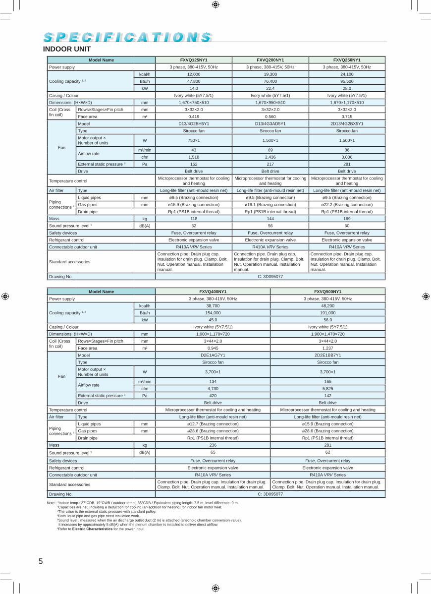
Model Name FXVQ125NY1 FXVQ200NY1 FXVQ250NY1
Power supply 3 phase, 380-415V, 50Hz 3 phase, 380-415V, 50Hz 3 phase, 380-415V, 50Hz
Cooling capacity 1, 2
kcal/h 12,000 19,300 24,100
Btu/h 47,800 76,400 95,500
kW 14.0 22.4 28.0
Casing / Colour Ivory white (5Y7.5/1) Ivory white (5Y7.5/1) Ivory white (5Y7.5/1)
Dimensions: (H×W×D) mm 1,670×750×510 1,670×950×510 1,670×1,170×510
Coil (Cross fin coil)
Rows×Stages×Fin pitch mm 3×32×2.0 3×32×2.0 3×32×2.0
Face area m² 0.419 0.560 0.715
Fan
Model D13/4G2BH5Y1 D13/4G3AD5Y1 2D13/4G2BX5Y1
Type Sirocco fan Sirocco fan Sirocco fan
Motor output ×Number of units
W 750×1 1,500×1 1,500×1
Airflow ratem³/min 43 69 86
cfm 1,518 2,436 3,036
External static pressure 3 Pa 152 217 281
Drive Belt drive Belt drive Belt drive
Temperature controlMicroprocessor thermostat for cooling
and heatingMicroprocessor thermostat for cooling
and heatingMicroprocessor thermostat for cooling
and heating
Air filter Type Long-life filter (anti-mould resin net) Long-life filter (anti-mould resin net) Long-life filter (anti-mould resin net)
Piping connections 4
Liquid pipes mm ø9.5 (Brazing connection) ø9.5 (Brazing connection) ø9.5 (Brazing connection)
Gas pipes mm ø15.9 (Brazing connection) ø19.1 (Brazing connection) ø22.2 (Brazing connection)
Drain pipe Rp1 (PS1B internal thread) Rp1 (PS1B internal thread) Rp1 (PS1B internal thread)
Mass kg 118 144 169
Sound pressure level 5 dB(A) 52 56 60
Safety devices Fuse, Overcurrent relay Fuse, Overcurrent relay Fuse, Overcurrent relay
Refrigerant control Electronic expansion valve Electronic expansion valve Electronic expansion valve
Connectable outdoor unit R410A VRV Series R410A VRV Series R410A VRV Series
Standard accessories
Connection pipe. Drain plug cap. Insulation for drain plug. Clamp. Bolt. Nut. Operation manual. Installation manual.
Connection pipe. Drain plug cap. Insulation for drain plug. Clamp. Bolt. Nut. Operation manual. Installation manual.
Connection pipe. Drain plug cap. Insulation for drain plug. Clamp. Bolt. Nut. Operation manual. Installation manual.
Drawing No. C: 3D095077
Model Name FXVQ400NY1 FXVQ500NY1
Power supply 3 phase, 380-415V, 50Hz 3 phase, 380-415V, 50Hz
Cooling capacity 1, 2
kcal/h 38,700 48,200
Btu/h 154,000 191,000
kW 45.0 56.0
Casing / Colour Ivory white (5Y7.5/1) Ivory white (5Y7.5/1)
Dimensions: (H×W×D) mm 1,900×1,170×720 1,900×1,470×720
Coil (Cross fin coil)
Rows×Stages×Fin pitch mm 3×44×2.0 3×44×2.0
Face area m² 0.945 1.237
Fan
Model D2E1AG7Y1 2D2E1BB7Y1
Type Sirocco fan Sirocco fan
Motor output ×Number of units
W 3,700×1 3,700×1
Airflow ratem³/min 134 165
cfm 4,730 5,825
External static pressure 3 Pa 420 142
Drive Belt drive Belt drive
Temperature control Microprocessor thermostat for cooling and heating Microprocessor thermostat for cooling and heating
Air filter Type Long-life filter (anti-mould resin net) Long-life filter (anti-mould resin net)
Piping connections 4
Liquid pipes mm ø12.7 (Brazing connection) ø15.9 (Brazing connection)
Gas pipes mm ø28.6 (Brazing connection) ø28.6 (Brazing connection)
Drain pipe Rp1 (PS1B internal thread) Rp1 (PS1B internal thread)
Mass kg 236 281
Sound pressure level 5 dB(A) 65 62
Safety devices Fuse, Overcurrent relay Fuse, Overcurrent relay
Refrigerant control Electronic expansion valve Electronic expansion valve
Connectable outdoor unit R410A VRV Series R410A VRV Series
Standard accessoriesConnection pipe. Drain plug cap. Insulation for drain plug. Clamp. Bolt. Nut. Operation manual. Installation manual.
Connection pipe. Drain plug cap. Insulation for drain plug. Clamp. Bolt. Nut. Operation manual. Installation manual.
Drawing No. C: 3D095077
Note : 1Indoor temp.: 27°CDB, 19°CWB / outdoor temp.: 35°CDB / Equivalent piping length: 7.5 m, level difference: 0 m.2Capacities are net, including a deduction for cooling (an addition for heating) for indoor fan motor heat.3The value is the external static pressure with standard pulley.4Both liquid pipe and gas pipe need insulation work.5Sound level : measured when the air discharge outlet duct (2 m) is attached (anechoic chamber conversion value). It increases by approximately 5 dB(A) when the plenum chamber is installed to deliver direct airflow.
6Refer to Electric Characteristics for the power input.
INDOOR UNIT
5

Model Name RXQ8TY1(E) RXQ10TY1(E)
Power Supply 3 phase, 380-415V, 50Hz 3 phase, 380-415V, 50Hz
Cooling Capacity 1
kcal/h 19,300 24,100
Btu/h 76,400 95,500
kW 22.4 28.0
Casing Color Ivory white (5Y7.5/1) Ivory white (5Y7.5/1)
Dimensions: (H×W×D) mm 1,657×930×765 1,657×930×765
Heat Exchanger Cross fin coil Cross fin coil
Comp.
Type Hermetically sealed scroll type Hermetically sealed scroll type
Displacement m³/h 16.24 24.37
Number of Revolutions r/min 7,668 7,650
Motor Output× Number of Units
kW 3.4×1 4.1×1
Starting Method Soft start Soft start
Fan
Type Propeller fan Propeller fan
Motor Output kW 0.55×1 0.55×1
Airflow Rate m³/min 157 165
Drive Direct drive Direct drive
Connecting Pipes
Liquid Pipe mm ø9.5 C1220T (Brazing connection) ø9.5 C1220T (Brazing connection)
Gas Pipe mm ø19.1 C1220T (Brazing connection) ø22.2 C1220T (Brazing connection)
Mass kg 185 195
Sound pressure level 2 dB(A) 56 57
Safety DevicesHigh pressure switch, Fan driver overload protector, Over current relay, Inverter overload protector
High pressure switch, Fan driver overload protector, Over current relay, Inverter overload protector
Capacity Control % 20-100 16-100
Refrigerant
Refrigerant Name R410A R410A
Charge kg 5.9 6.0
Control Electronic expansion valve Electronic expansion valve
Refrigerator Oil Refer to the nameplate of compressor Refer to the nameplate of compressor
Standard AccessoriesInstallation manual, Operation manual, Connection pipes, Clamps
Installation manual, Operation manual, Connection pipes, Clamps
Drawing No. C: 4D084877A C: 4D084980A
Model Name RXQ16TY1(E) RXQ20TY1(E)
Power Supply 3 phase, 380-415V, 50Hz 3 phase, 380-415V, 50Hz
Cooling Capacity 1
kcal/h 38,700 48,200
Btu/h 154,000 191,000
kW 45.0 56.0
Casing Color Ivory white (5Y7.5/1) Ivory white (5Y7.5/1)
Dimensions: (H×W×D) mm 1,657×1,240×765 1,657×1,240×765
Heat Exchanger Cross fin coil Cross fin coil
Comp.
Type Hermetically sealed scroll type Hermetically sealed scroll type
Displacement m³/h 16.27+17.54 16.90+26.28
Number of Revolutions r/min 7,680+8,280 7,980+8,250
Motor Output× Number of Units
kW (3.6×1)+(3.7×1) (4.6×1)+(5.5×1)
Starting Method Soft start Soft start
Fan
Type Propeller fan Propeller fan
Motor Output kW 0.75×2 0.75×2
Airflow Rate m³/min 233 268
Drive Direct drive Direct drive
Connecting Pipes
Liquid Pipe mm ø12.7 C1220T (Brazing connection) ø15.9 C1220T (Brazing connection)
Gas Pipe mm ø28.6 C1220T (Brazing connection) ø28.6 C1220T (Brazing connection)
Mass kg 285 320
Sound pressure level 2 dB(A) 61 65
Safety DevicesHigh pressure switch, Fan driver overload protector, Over current relay, Inverter overload protector
High pressure switch, Fan driver overload protector, Over current relay, Inverter overload protector
Capacity Control % 10-100 8-100
Refrigerant
Refrigerant Name R410A R410A
Charge kg 10.4 11.8
Control Electronic expansion valve Electronic expansion valve
Refrigerator Oil Refer to the nameplate of compressor Refer to the nameplate of compressor
Standard AccessoriesInstallation manual, Operation manual, Connection pipes, Clamps
Installation manual, Operation manual, Connection pipes, Clamps
Drawing No. C: 4D084977A C: 4D084880A
Note : 1Indoor temp.: 27°CDB, 19°CWB / outdoor temp.: 35°CDB / Equivalent piping length: 7.5 m, level difference: 0 m.2Anechoic chamber conversion value, measured at a point 1 m in front of the unit at a height of 1.5m.
During actual operation, these values are normally somewhat higher as a result of ambient conditions. 3Refer to Capacity Tables for the power input (PI) (Compressor + Outdoor fan motor).
4Models with (E) feature components treated for heat and rust corrosion resistance, such as external panels, fan motor, and electric component box, in addition to the fins of the heat exchanger. These models are designed specifically for use in areas which are subject to salt damage and atmospheric pollution. Please contact Daikin for more information.
OUTDOOR UNIT
6
DIMENSIONS (Unit: mm)
3D081764B
INDOOR UNIT
FXVQ125NY1
FXVQ200NY1
3D081765B
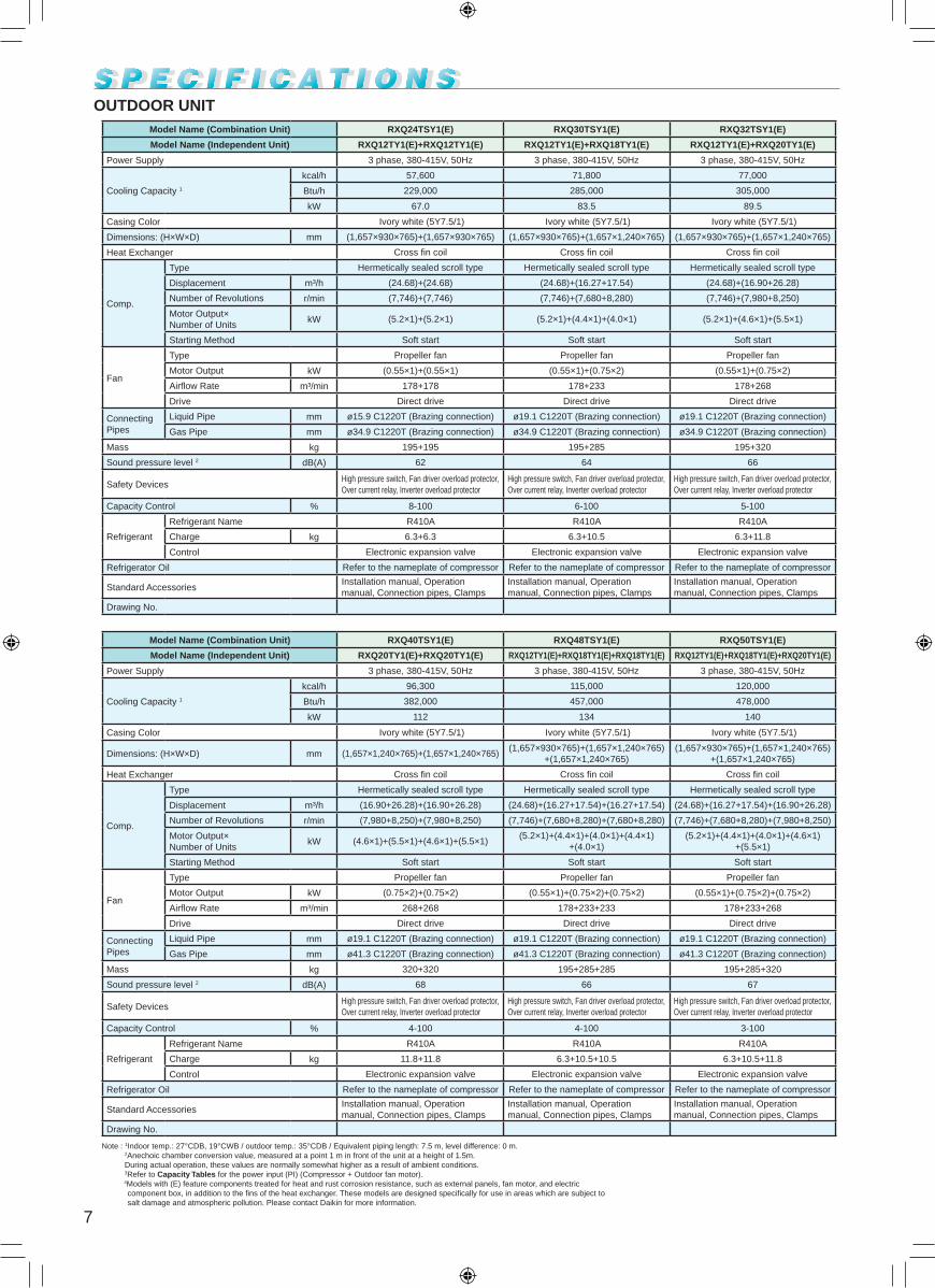
Model Name (Combination Unit) RXQ24TSY1(E) RXQ30TSY1(E) RXQ32TSY1(E)
Model Name (Independent Unit) RXQ12TY1(E)+RXQ12TY1(E) RXQ12TY1(E)+RXQ18TY1(E) RXQ12TY1(E)+RXQ20TY1(E)
Power Supply 3 phase, 380-415V, 50Hz 3 phase, 380-415V, 50Hz 3 phase, 380-415V, 50Hz
Cooling Capacity 1
kcal/h 57,600 71,800 77,000
Btu/h 229,000 285,000 305,000
kW 67.0 83.5 89.5
Casing Color Ivory white (5Y7.5/1) Ivory white (5Y7.5/1) Ivory white (5Y7.5/1)
Dimensions: (H×W×D) mm (1,657×930×765)+(1,657×930×765) (1,657×930×765)+(1,657×1,240×765) (1,657×930×765)+(1,657×1,240×765)
Heat Exchanger Cross fin coil Cross fin coil Cross fin coil
Comp.
Type Hermetically sealed scroll type Hermetically sealed scroll type Hermetically sealed scroll type
Displacement m³/h (24.68)+(24.68) (24.68)+(16.27+17.54) (24.68)+(16.90+26.28)
Number of Revolutions r/min (7,746)+(7,746) (7,746)+(7,680+8,280) (7,746)+(7,980+8,250)
Motor Output× Number of Units
kW (5.2×1)+(5.2×1) (5.2×1)+(4.4×1)+(4.0×1) (5.2×1)+(4.6×1)+(5.5×1)
Starting Method Soft start Soft start Soft start
Fan
Type Propeller fan Propeller fan Propeller fan
Motor Output kW (0.55×1)+(0.55×1) (0.55×1)+(0.75×2) (0.55×1)+(0.75×2)
Airflow Rate m³/min 178+178 178+233 178+268
Drive Direct drive Direct drive Direct drive
Connecting Pipes
Liquid Pipe mm ø15.9 C1220T (Brazing connection) ø19.1 C1220T (Brazing connection) ø19.1 C1220T (Brazing connection)
Gas Pipe mm ø34.9 C1220T (Brazing connection) ø34.9 C1220T (Brazing connection) ø34.9 C1220T (Brazing connection)
Mass kg 195+195 195+285 195+320
Sound pressure level 2 dB(A) 62 64 66
Safety DevicesHigh pressure switch, Fan driver overload protector, Over current relay, Inverter overload protector
High pressure switch, Fan driver overload protector, Over current relay, Inverter overload protector
High pressure switch, Fan driver overload protector, Over current relay, Inverter overload protector
Capacity Control % 8-100 6-100 5-100
Refrigerant
Refrigerant Name R410A R410A R410A
Charge kg 6.3+6.3 6.3+10.5 6.3+11.8
Control Electronic expansion valve Electronic expansion valve Electronic expansion valve
Refrigerator Oil Refer to the nameplate of compressor Refer to the nameplate of compressor Refer to the nameplate of compressor
Standard AccessoriesInstallation manual, Operation manual, Connection pipes, Clamps
Installation manual, Operation manual, Connection pipes, Clamps
Installation manual, Operation manual, Connection pipes, Clamps
Drawing No.
Model Name (Combination Unit) RXQ40TSY1(E) RXQ48TSY1(E) RXQ50TSY1(E)
Model Name (Independent Unit) RXQ20TY1(E)+RXQ20TY1(E) RXQ12TY1(E)+RXQ18TY1(E)+RXQ18TY1(E) RXQ12TY1(E)+RXQ18TY1(E)+RXQ20TY1(E)
Power Supply 3 phase, 380-415V, 50Hz 3 phase, 380-415V, 50Hz 3 phase, 380-415V, 50Hz
Cooling Capacity 1
kcal/h 96,300 115,000 120,000
Btu/h 382,000 457,000 478,000
kW 112 134 140
Casing Color Ivory white (5Y7.5/1) Ivory white (5Y7.5/1) Ivory white (5Y7.5/1)
Dimensions: (H×W×D) mm (1,657×1,240×765)+(1,657×1,240×765)(1,657×930×765)+(1,657×1,240×765)
+(1,657×1,240×765)(1,657×930×765)+(1,657×1,240×765)
+(1,657×1,240×765)
Heat Exchanger Cross fin coil Cross fin coil Cross fin coil
Comp.
Type Hermetically sealed scroll type Hermetically sealed scroll type Hermetically sealed scroll type
Displacement m³/h (16.90+26.28)+(16.90+26.28) (24.68)+(16.27+17.54)+(16.27+17.54) (24.68)+(16.27+17.54)+(16.90+26.28)
Number of Revolutions r/min (7,980+8,250)+(7,980+8,250) (7,746)+(7,680+8,280)+(7,680+8,280) (7,746)+(7,680+8,280)+(7,980+8,250)
Motor Output× Number of Units
kW (4.6×1)+(5.5×1)+(4.6×1)+(5.5×1)(5.2×1)+(4.4×1)+(4.0×1)+(4.4×1)
+(4.0×1)(5.2×1)+(4.4×1)+(4.0×1)+(4.6×1)
+(5.5×1)
Starting Method Soft start Soft start Soft start
Fan
Type Propeller fan Propeller fan Propeller fan
Motor Output kW (0.75×2)+(0.75×2) (0.55×1)+(0.75×2)+(0.75×2) (0.55×1)+(0.75×2)+(0.75×2)
Airflow Rate m³/min 268+268 178+233+233 178+233+268
Drive Direct drive Direct drive Direct drive
Connecting Pipes
Liquid Pipe mm ø19.1 C1220T (Brazing connection) ø19.1 C1220T (Brazing connection) ø19.1 C1220T (Brazing connection)
Gas Pipe mm ø41.3 C1220T (Brazing connection) ø41.3 C1220T (Brazing connection) ø41.3 C1220T (Brazing connection)
Mass kg 320+320 195+285+285 195+285+320
Sound pressure level 2 dB(A) 68 66 67
Safety DevicesHigh pressure switch, Fan driver overload protector, Over current relay, Inverter overload protector
High pressure switch, Fan driver overload protector, Over current relay, Inverter overload protector
High pressure switch, Fan driver overload protector, Over current relay, Inverter overload protector
Capacity Control % 4-100 4-100 3-100
Refrigerant
Refrigerant Name R410A R410A R410A
Charge kg 11.8+11.8 6.3+10.5+10.5 6.3+10.5+11.8
Control Electronic expansion valve Electronic expansion valve Electronic expansion valve
Refrigerator Oil Refer to the nameplate of compressor Refer to the nameplate of compressor Refer to the nameplate of compressor
Standard AccessoriesInstallation manual, Operation manual, Connection pipes, Clamps
Installation manual, Operation manual, Connection pipes, Clamps
Installation manual, Operation manual, Connection pipes, Clamps
Drawing No.
OUTDOOR UNIT
Note : 1Indoor temp.: 27°CDB, 19°CWB / outdoor temp.: 35°CDB / Equivalent piping length: 7.5 m, level difference: 0 m.2Anechoic chamber conversion value, measured at a point 1 m in front of the unit at a height of 1.5m.
During actual operation, these values are normally somewhat higher as a result of ambient conditions. 3Refer to Capacity Tables for the power input (PI) (Compressor + Outdoor fan motor).
4Models with (E) feature components treated for heat and rust corrosion resistance, such as external panels, fan motor, and electric component box, in addition to the fins of the heat exchanger. These models are designed specifically for use in areas which are subject to salt damage and atmospheric pollution. Please contact Daikin for more information.
7

DIMENSIONS (Unit: mm)
3D081764B
INDOOR UNIT
FXVQ125NY1
FXVQ200NY1
3D081765B
3D081764B
8
DIMENSIONS (Unit: mm)
3D081766B
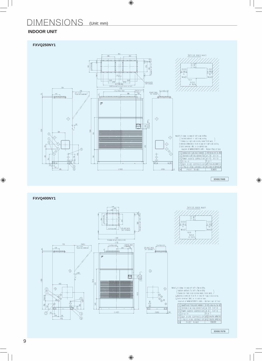
INDOOR UNIT
FXVQ250NY1
FXVQ400NY1 RXQ8TY1RXQ10TY1
3D081767B
3D085649A
C: 3D084511C
INDOOR UNIT / OUTDOOR UNIT
FXVQ500NY1
3D081766A
3D081767A
9

DIMENSIONS (Unit: mm)
3D081766B
INDOOR UNIT
FXVQ250NY1
FXVQ400NY1 RXQ8TY1RXQ10TY1
3D081767B
3D085649A
C: 3D084511C
INDOOR UNIT / OUTDOOR UNIT
FXVQ500NY1
3D085649
C: 3
D08
4511
C
Unit (mm)
10
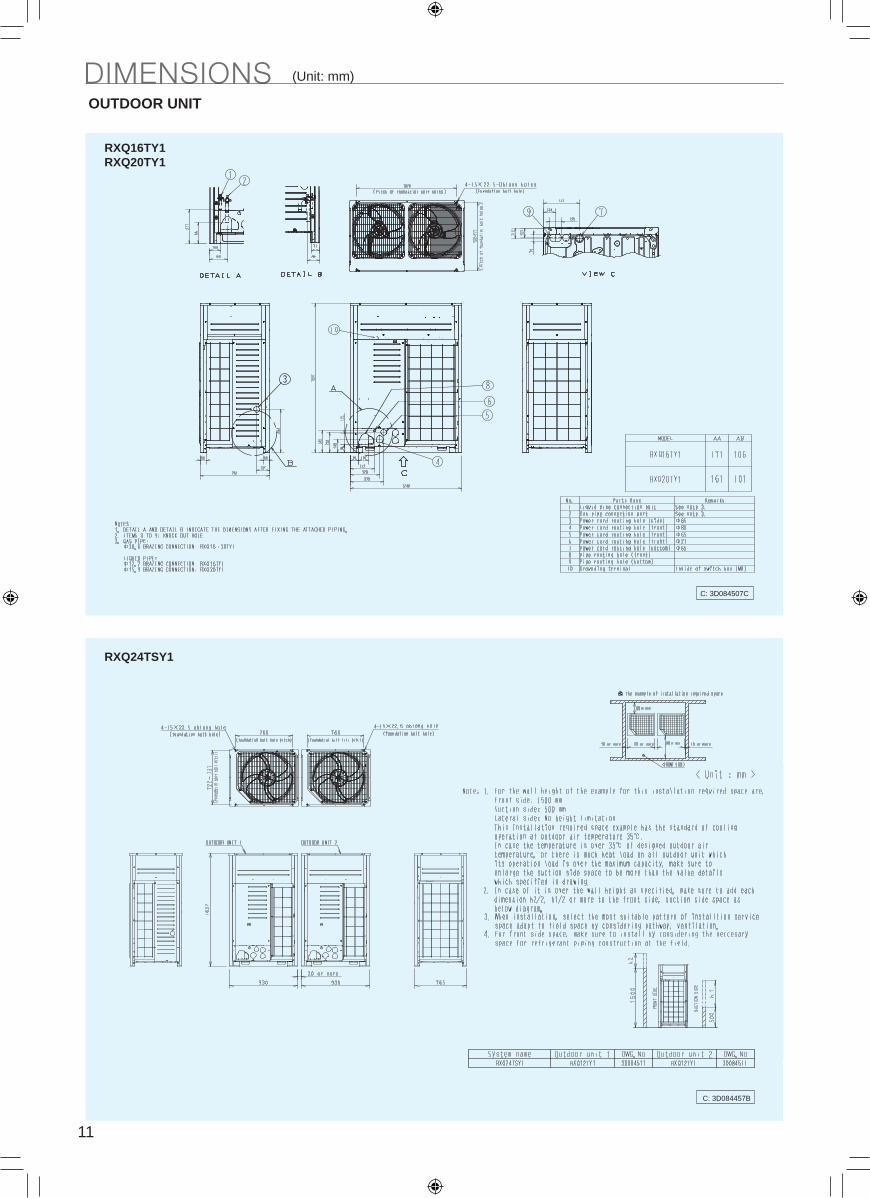
DIMENSIONS (Unit: mm)
C: 3D084507C
OUTDOOR UNIT
RXQ16TY1RXQ20TY1
RXQ24TSY1 RXQ40TSY1
C: 3D084457B
C: 3D084458B
C: 3D084462B
OUTDOOR UNIT
RXQ30TSY1RXQ32TSY1
11
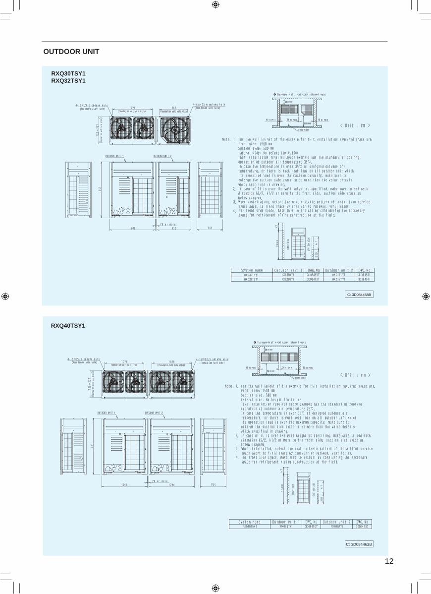
DIMENSIONS (Unit: mm)
C: 3D084507C
OUTDOOR UNIT
RXQ16TY1RXQ20TY1
RXQ24TSY1 RXQ40TSY1
C: 3D084457B
C: 3D084458B
C: 3D084462B
OUTDOOR UNIT
RXQ30TSY1RXQ32TSY1
12

DIMENSIONS (Unit: mm)
C: 3D084464B
OUTDOOR UNIT
RXQ48TSY1
RXQ60TNY1 RXQ40TSY1
C: 3D084465B
C: 3D084458B
C: 3D084462B
OUTDOOR UNIT
RXQ30TSY1RXQ32TSY1
100 or more
900 or more
100 or more
500 or more
Service Area
100 or more
900 or more
100 or more
500 or more
Service Area
Space required for indoor unit installation (Unit: mm) WIRING DIAGRAMS
3D093434
INDOOR UNIT
FXVQ125NY1FXVQ200NY1FXVQ250NY1
FXVQ400NY1FXVQ500NY1
3D093435
13

DIMENSIONS (Unit: mm)
C: 3D084464B
OUTDOOR UNIT
RXQ48TSY1
RXQ60TNY1 RXQ40TSY1
C: 3D084465B
C: 3D084458B
C: 3D084462B
OUTDOOR UNIT
RXQ30TSY1RXQ32TSY1
100 or more
900 or more
100 or more
500 or more
Service Area
100 or more
900 or more
100 or more
500 or more
Service Area
Space required for indoor unit installation (Unit: mm) WIRING DIAGRAMS
3D093434
INDOOR UNIT
FXVQ125NY1FXVQ200NY1FXVQ250NY1
FXVQ400NY1FXVQ500NY1
3D093435
14

WIRING DIAGRAMS
1. Wiring
2. Depending on whether [voltage input] or [non voltage input], connect the wiring as shown below. Input/Output for External Control3. Depending on whether [voltage input] or [non voltage input], connect the wiring as shown below. Input with Voltage. Set the Voltage/Non voltage changeover switch (SS1) to VOLT.
Input with No Voltage. Set the Voltage/Non voltage changeover switch (SS1) to NON VOLT.
4. Display Signal Retrieval (Output) The normal operation output terminals (W1, W2) and error output terminals (W3, W4) are non-voltage output contacts. (Permissive current is 10mA~3A per contact.)
Output is as given below.
Electric Wiring Work and initial Setting for A2P
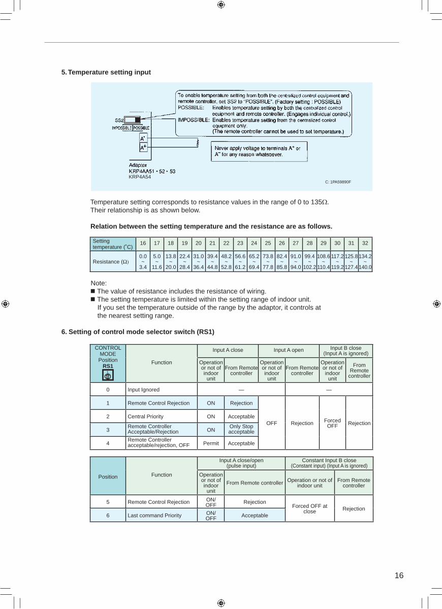
5. Temperature setting input
Temperature setting corresponds to resistance values in the range of 0 to 135Ω. Their relationship is as shown below.
Relation between the setting temperature and the resistance are as follows.
Note: The value of resistance includes the resistance of wiring. The setting temperature is limited within the setting range of indoor unit. If you set the temperature outside of the range by the adaptor, it controls at the nearest setting range.
6. Setting of control mode selector switch (RS1)
KRP4A54C: 1PA59890F
Output
SystemBoth Ry1 and Ry2 is OFF. Only Ry1 is ON. Only Ry2 is ON.
Group control OFF All normal operationAt least one unit is stopped due to error or transmission error between the adaptor and the indoor unit.
C: 1PA59890F
15
WIRING DIAGRAMS
1. Wiring
2. Depending on whether [voltage input] or [non voltage input], connect the wiring as shown below. Input/Output for External Control3. Depending on whether [voltage input] or [non voltage input], connect the wiring as shown below. Input with Voltage. Set the Voltage/Non voltage changeover switch (SS1) to VOLT.
Input with No Voltage. Set the Voltage/Non voltage changeover switch (SS1) to NON VOLT.
4. Display Signal Retrieval (Output) The normal operation output terminals (W1, W2) and error output terminals (W3, W4) are non-voltage output contacts. (Permissive current is 10mA~3A per contact.)
Output is as given below.
Electric Wiring Work and initial Setting for A2P
5. Temperature setting input
Temperature setting corresponds to resistance values in the range of 0 to 135Ω. Their relationship is as shown below.
Relation between the setting temperature and the resistance are as follows.
Note: The value of resistance includes the resistance of wiring. The setting temperature is limited within the setting range of indoor unit. If you set the temperature outside of the range by the adaptor, it controls at the nearest setting range.
6. Setting of control mode selector switch (RS1)
KRP4A54C: 1PA59890F
Settingtemperature (˚C)
16 17 18 19 20 21 22 23 24 25 26 27 28 29 30 31 32
Resistance (Ω)0.0~
3.4
5.0~
11.6
13.8~
20.0
22.4~
28.4
31.0~
36.4
39.4~
44.8
48.2~
52.8
56.6~
61.2
65.2~
69.4
73.8~
77.8
82.4~
85.8
91.0~
94.0
99.4~
102.2
108.6~
110.4
117.2~
119.2
125.8~
127.4
134.2~
140.0
CONTROLMODE Position
RS1Function
Input A close Input A open Input B close (Input A is ignored)
Operationor not ofindoor
unit
From Remotecontroller
Operationor not ofindoor
unit
From Remotecontroller
Operationor not ofindoor
unit
From Remote
controller
0 Input Ignored — —
1 Remote Control Rejection ON Rejection
OFF Rejection ForcedOFF Rejection
2 Central Priority ON Acceptable
3Remote ControllerAcceptable/Rejection ON
Only Stopacceptable
4Remote Controlleracceptable/rejection, OFF Permit Acceptable
Position Function
Input A close/open (pulse input)
Constant Input B close (Constant input) (Input A is ignored)
Operationor not ofindoor
unit
From Remote controller Operation or not ofindoor unit
From Remotecontroller
5 Remote Control Rejection ON/OFF Rejection
Forced OFF at close Rejection
6 Last command Priority ON/OFF Acceptable
1
16
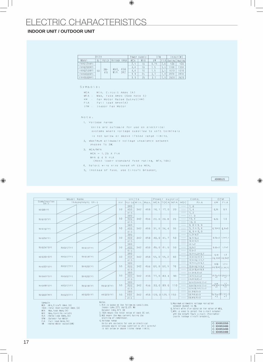
ELECTRIC CHARACTERISTICSINDOOR UNIT / OUTDOOR UNIT
4D095121
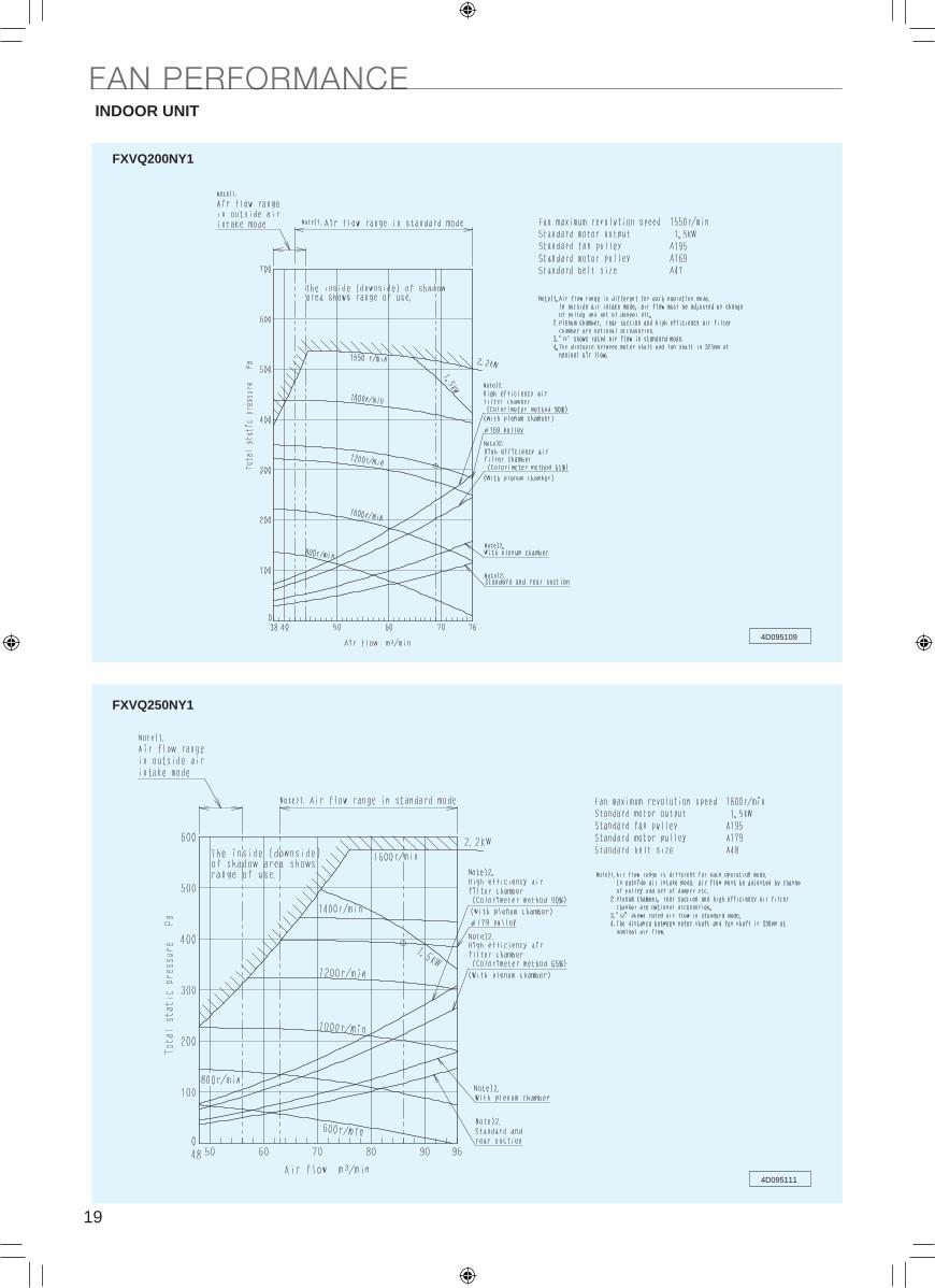
FAN PERFORMANCE
4D095109
4D095111
INDOOR UNIT
FXVQ200NY1
FXVQ250NY1
CAPACITY TABLES / FAN PERFORMANCEINDOOR UNITCAPACITY TABLES
FAN PERFORMANCE
CA13A279A
4D095108
FXVQ125NY1
17
C: 3D085335BC: 3D085348BC: 3D085349BC: 3D085338B
ELECTRIC CHARACTERISTICSINDOOR UNIT / OUTDOOR UNIT
4D095121
FAN PERFORMANCE
4D095109
4D095111
INDOOR UNIT
FXVQ200NY1
FXVQ250NY1
CAPACITY TABLES / FAN PERFORMANCEINDOOR UNITCAPACITY TABLES
FAN PERFORMANCE
CA13A279A
4D095108
FXVQ125NY1
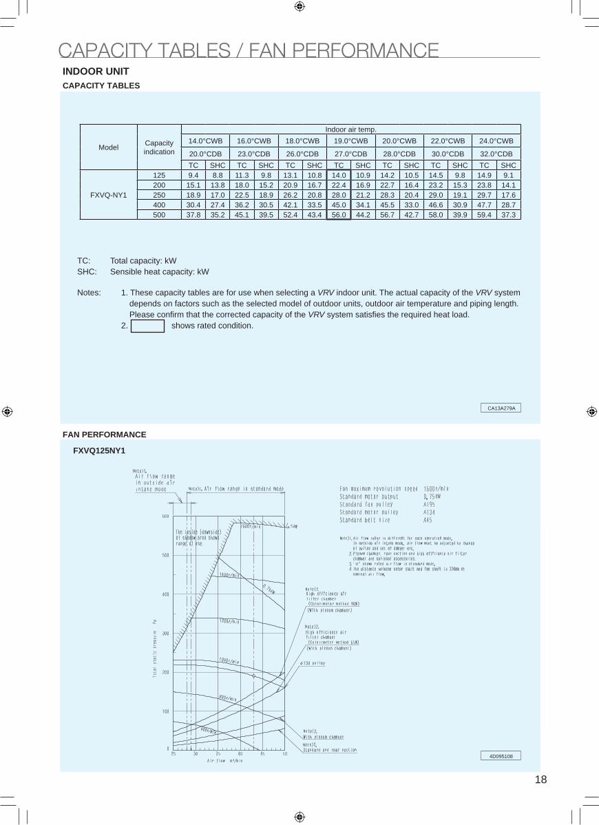
TC: Total capacity: kWSHC: Sensible heat capacity: kW
Notes: 1. These capacity tables are for use when selecting a VRV indoor unit. The actual capacity of the VRV system depends on factors such as the selected model of outdoor units, outdoor air temperature and piping length. Please confirm that the corrected capacity of the VRV system satisfies the required heat load.2. shows rated condition.
ModelCapacity indication
Indoor air temp.
14.0°CWB 16.0°CWB 18.0°CWB 19.0°CWB 20.0°CWB 22.0°CWB 24.0°CWB
20.0°CDB 23.0°CDB 26.0°CDB 27.0°CDB 28.0°CDB 30.0°CDB 32.0°CDB
TC SHC TC SHC TC SHC TC SHC TC SHC TC SHC TC SHC
FXVQ-NY1
125 9.4 8.8 11.3 9.8 13.1 10.8 14.0 10.9 14.2 10.5 14.5 9.8 14.9 9.1 200 15.1 13.8 18.0 15.2 20.9 16.7 22.4 16.9 22.7 16.4 23.2 15.3 23.8 14.1 250 18.9 17.0 22.5 18.9 26.2 20.8 28.0 21.2 28.3 20.4 29.0 19.1 29.7 17.6 400 30.4 27.4 36.2 30.5 42.1 33.5 45.0 34.1 45.5 33.0 46.6 30.9 47.7 28.7 500 37.8 35.2 45.1 39.5 52.4 43.4 56.0 44.2 56.7 42.7 58.0 39.9 59.4 37.3
18
ELECTRIC CHARACTERISTICSINDOOR UNIT / OUTDOOR UNIT
4D095121
FAN PERFORMANCE
4D095109
4D095111
INDOOR UNIT
FXVQ200NY1
FXVQ250NY1
19
INDOOR UNIT
4D095113 4D095080
4D095112
INDOOR UNIT
Overall
FXVQ125NY1
FXVQ400NY1
FXVQ500NY1
SOUND LEVELS

ELECTRIC CHARACTERISTICSINDOOR UNIT / OUTDOOR UNIT
4D095121
FAN PERFORMANCE
4D095109
4D095111
INDOOR UNIT
FXVQ200NY1
FXVQ250NY1
20
INDOOR UNIT
4D095113 4D095080
4D095112
INDOOR UNIT
Overall
FXVQ125NY1
FXVQ400NY1
FXVQ500NY1
SOUND LEVELS

21
INDOOR UNIT
4D095082
4D095081
INDOOR UNIT
OverallFXVQ200NY1
FXVQ250NY1
SOUND LEVELS
ModelSound pressure level
380-415V, 50Hz
FXVQ125NY1 52
FXVQ200NY1 56
FXVQ250NY1 60
FXVQ400NY1 65
FXVQ500NY1 62
Location of microphone (for sound pressure level) Notes:1. The operating conditions are assumed to be standard
(JIS conditions).
2. These operating values were obtained in anechoic
chamber (conversion values).
Sound level will vary depending on a range of factors
such as the construction (acoustic absorption coefficient)
of the particular room in which the equipment installed.
4D095080
4D095083 4D095088
4D095081 4D095082
FXVQ125NY1 FXVQ200NY1
FXVQ400NY1 FXVQ500NY1
FXVQ250NY1
Octave Band Level380-415V, 50Hz
dB(A)
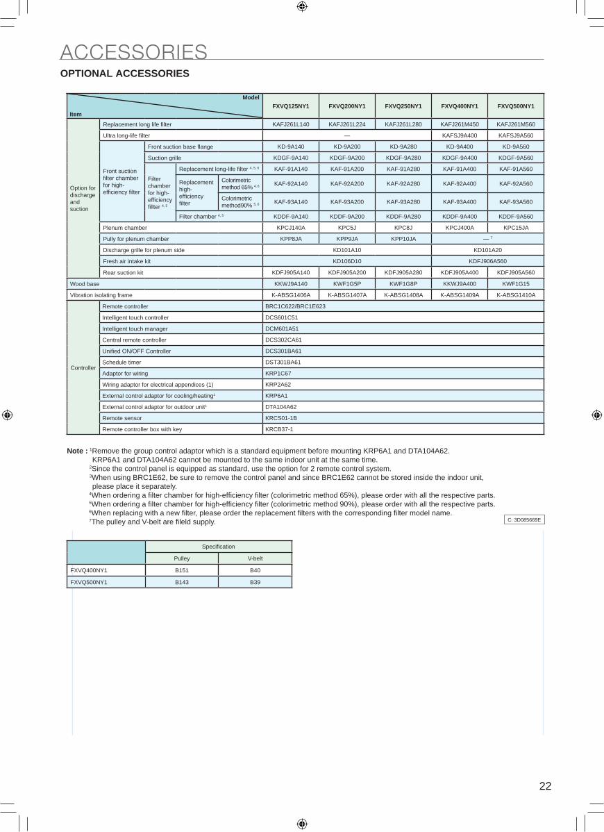
OPTIONAL ACCESSORIES
ACCESSORIES ACCESSORIES
22
INDOOR UNIT
4D095082
4D095081
INDOOR UNIT
OverallFXVQ200NY1
FXVQ250NY1
SOUND LEVELSOPTIONAL ACCESSORIES
ACCESSORIES ACCESSORIES
FXVQ125NY1 FXVQ200NY1 FXVQ250NY1 FXVQ400NY1 FXVQ500NY1
Option for discharge and suction
Replacement long life filter KAFJ261L140 KAFJ261L224 KAFJ261L280 KAFJ261M450 KAFJ261M560
Ultra long-life filter — KAFSJ9A400 KAFSJ9A560
Front suction filter chamber for high- efficiency filter
Front suction base flange KD-9A140 KD-9A200 KD-9A280 KD-9A400 KD-9A560
Suction grille KDGF-9A140 KDGF-9A200 KDGF-9A280 KDGF-9A400 KDGF-9A560
Filter chamber for high-efficiency fillter 4, 5
Replacement long-life filter 4, 5, 6 KAF-91A140 KAF-91A200 KAF-91A280 KAF-91A400 KAF-91A560
Replacement high-efficiency filter
Colorimetric
method 65% 4, 6 KAF-92A140 KAF-92A200 KAF-92A280 KAF-92A400 KAF-92A560
Colorimetric method90% 5, 6 KAF-93A140 KAF-93A200 KAF-93A280 KAF-93A400 KAF-93A560
Filter chamber 4, 5 KDDF-9A140 KDDF-9A200 KDDF-9A280 KDDF-9A400 KDDF-9A560
Plenum chamber KPCJ140A KPC5J KPC8J KPCJ400A KPC15JA
Pully for plenum chamber KPP8JA KPP9JA KPP10JA — 7
Discharge grille for plenum side KD101A10 KD101A20
Fresh air intake kit KD106D10 KDFJ906A560
Rear suction kit KDFJ905A140 KDFJ905A200 KDFJ905A280 KDFJ905A400 KDFJ905A560
Wood base KKWJ9A140 KWF1G5P KWF1G8P KKWJ9A400 KWF1G15
Vibration isolating frame K-ABSG1406A K-ABSG1407A K-ABSG1408A K-ABSG1409A K-ABSG1410A
Specification
Pulley V-belt
FXVQ400NY1 B151 B40
FXVQ500NY1 B143 B39
Note : 1Remove the group control adaptor which is a standard equipment before mounting KRP6A1 and DTA104A62. KRP6A1 and DTA104A62 cannot be mounted to the same indoor unit at the same time. 2Since the control panel is equipped as standard, use the option for 2 remote control system. 3When using BRC1E62, be sure to remove the control panel and since BRC1E62 cannot be stored inside the indoor unit, please place it separately. 4When ordering a filter chamber for high-efficiency filter (colorimetric method 65%), please order with all the respective parts. 5When ordering a filter chamber for high-efficiency filter (colorimetric method 90%), please order with all the respective parts. 6When replacing with a new filter, please order the replacement filters with the corresponding filter model name. 7The pulley and V-belt are fileld supply. C: 3D085669E
Model
Item
Controller
Remote controller BRC1C622/BRC1E623
Intelligent touch controller DCS601C51
Intelligent touch manager DCM601A51
Central remote controller DCS302CA61
Unified ON/OFF Controller DCS301BA61
Schedule timer DST301BA61
Adaptor for wiring KRP1C67
Wiring adaptor for electrical appendices (1) KRP2A62
External control adaptor for cooling/heating1 KRP6A1
External control adaptor for outdoor unit1 DTA104A62
Remote sensor KRCS01-1B
Remote controller box with key KRCB37-1

23
KAFJ261L140 · 224 · 280 / KAFJ261M450 · 560 — Replacement Long-life Filter
KAFSJ9A400 · 560 — Ultra Long-life Filter Unit
483 315 20KAFJ261M450
483 315 20KAFJ261M560
700 198 15700 403 15
KAFJ261L280
700 403 15KAFJ261L224
700 198 15700 403 15
KAFJ261L140
A X B X CModel
8
KAFJ261M560
63 (Large:2, Small:1)2
2,500 hours (dust concentration 0.15 mg/m³)Life (h)
Mildew proof resin netMaterials
2 (each 1)Number of Sheets Included
49.0Final Pressure Loss (Pa)9.0
Average Efficiency (%)
KAFJ261M450KAFJ261L280KAFJ261L224KAFJ261L140Model
Item
Materials Filter frame
KAFJ261L140
• Can be water-washed. Can be reused.
Dimensions Unit (mm)
Initial Pressure Loss (Pa)40 (Gravity method) 50 (Gravity method)
J: D3K2979
317
B
478KAFSJ9A400•560
AModel
3.5
Reinforcing plate/frame/filter material
6
Mildew proof resin net
10,000 hours (dust concentration 0.17 mg/m³)
5,000 hours (dust concentration 0.35 mg/m³)
49
25
45 or more (Gravity method)
KAFSJ9A400
4.5
8
KAFSJ9A560
Component Parts
Number of Sheets Included
Life (h)
Materials
Mass (kg)
Final Pressure Loss (Pa)
Initial Pressure Loss (Pa)
Precipitation Efficiency (%)
ModelItem
In case of KAFSJ9A
KAFS1A
• Used after replacing with a standard filter. (No main body remodeling)
• Dust collection efficiency (45% gravity method) equivalent to that of long-life filter.The interval between cleaning cycles is extended by four times or more.
• If installed in a pachinko parlour, maintenance is required only once a year. (Long-life filter: 3 months)
• Can be synchronized with coil cleaning (Approximately once a year in pachinko parlours) to realize economy of maintenance.
Caution1.The filter should be cleaned (with water)
regularly according to the table to the right.
2.The filter unit collects dirt and dust, but, since it collects cigarette smoke insufficiently, use in combination with an air purifier will improve effectiveness.
Both life shows a case that "the air purifier" is installed.
Dimensions
Approximately every 10,000 hoursLocations with Little Dust (e.g. offices)
Approximately every 5,000 hoursLocations with Much Dust (e.g. Pachinko parlours, etc.)
Approximately Every 10,000 HoursMounting Locations
Mounting diagram
Unit (mm)
JC: D3K2359
OPTIONAL ACCESSORIES
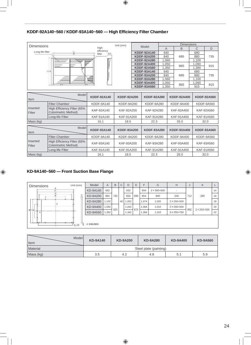
ACCESSORIES ACCESSORIESKDDF-92A140~560 / KDDF-93A140~560 — High Efficiency Filter Chamber
KD-9A140~560 — Front Suction Base Flange
26.0
KAF-91A400
KAF-92A400
KDDF-9A400
KDDF-92A400
32.0
KAF-91A560
KAF-92A560
KDDF-9A560
KDDF-92A560
22.3
KAF-91A280
KAF-92A280
KDDF-9A280
18.5
KAF-91A200
KAF-92A200
KDDF-9A200
KAF-91A140Long-life Filter
KAF-92A140High Efficiency Filter (65% Colorimetric Method)
Filter Chamber
16.1Mass (kg)
KDDF-9A140InsertedFilter
KDDF-92A280KDDF-92A200KDDF-92A140Model
Item
Dimensions
Long-life filter
9151,090
8651,050KDDF-93A400
9151,350KDDF-93A560
1,3901,350KDDF-92A560
735680
685640KDDF-93A140
880840KDDF-93A2001,1001,060KDDF-93A280
DCBDimensions
Model
915
735
1,0901,100880680
865
685
1,050KDDF-92A4001,060KDDF-92A280840KDDF-92A200640KDDF-92A140A
26.0
KAF-91A400
KAF-93A400
KDDF-9A400
KDDF-93A400
32.0
KAF-91A560
KAF-93A560
KDDF-9A560
22.3
KAF-91A280
KAF-93A280
KDDF-9A280
18.5
KAF-91A200
KAF-93A200
KDDF-9A200
KAF-91A140Long-life Filter
KAF-93A140High Efficiency Filter (65% Colorimetric Method)
Filter Chamber
16.1Mass (kg)
KDDF-9A140InsertedFilter
KDDF-93A560KDDF-93A280KDDF-93A200KDDF-93A140Model
Item
Highefficiencyfilter
Unit (mm)
Dimensions
202 250=500892
2 250=5001,0101,064870
1,042
40
9201,092KD-9A400
16
182 250=5001,0201,0741,052
250800854832
Model
1,342
632
D
690
E
1,364
654
F
1,310
2 300=600
G
3 250=750
-
H
712
J
280
K LCB
22
14
740
1,392KD-9A560
1,102KD-9A280
882KD-9A200
682KD-9A140
A
3.5
KD-9A140
5.95.14.84.2Mass (kg)
)gnitniap( etalp leetSlairetaM
KD-9A560KD-9A400KD-9A280KD-9A200Model
Item
Unit (mm)
J: D3K2903
24
KAFJ261L140 · 224 · 280 / KAFJ261M450 · 560 — Replacement Long-life Filter
KAFSJ9A400 · 560 — Ultra Long-life Filter Unit
483 315 20KAFJ261M450
483 315 20KAFJ261M560
700 198 15700 403 15
KAFJ261L280
700 403 15KAFJ261L224
700 198 15700 403 15
KAFJ261L140
A X B X CModel
8
KAFJ261M560
63 (Large:2, Small:1)2
2,500 hours (dust concentration 0.15 mg/m³)Life (h)
Mildew proof resin netMaterials
2 (each 1)Number of Sheets Included
49.0Final Pressure Loss (Pa)9.0
Average Efficiency (%)
KAFJ261M450KAFJ261L280KAFJ261L224KAFJ261L140Model
Item
Materials Filter frame
KAFJ261L140
• Can be water-washed. Can be reused.
Dimensions Unit (mm)
Initial Pressure Loss (Pa)40 (Gravity method) 50 (Gravity method)
J: D3K2979
317
B
478KAFSJ9A400•560
AModel
3.5
Reinforcing plate/frame/filter material
6
Mildew proof resin net
10,000 hours (dust concentration 0.17 mg/m³)
5,000 hours (dust concentration 0.35 mg/m³)
49
25
45 or more (Gravity method)
KAFSJ9A400
4.5
8
KAFSJ9A560
Component Parts
Number of Sheets Included
Life (h)
Materials
Mass (kg)
Final Pressure Loss (Pa)
Initial Pressure Loss (Pa)
Precipitation Efficiency (%)
ModelItem
In case of KAFSJ9A
KAFS1A
• Used after replacing with a standard filter. (No main body remodeling)
• Dust collection efficiency (45% gravity method) equivalent to that of long-life filter.The interval between cleaning cycles is extended by four times or more.
• If installed in a pachinko parlour, maintenance is required only once a year. (Long-life filter: 3 months)
• Can be synchronized with coil cleaning (Approximately once a year in pachinko parlours) to realize economy of maintenance.
Caution1.The filter should be cleaned (with water)
regularly according to the table to the right.
2.The filter unit collects dirt and dust, but, since it collects cigarette smoke insufficiently, use in combination with an air purifier will improve effectiveness.
Both life shows a case that "the air purifier" is installed.
Dimensions
Approximately every 10,000 hoursLocations with Little Dust (e.g. offices)
Approximately every 5,000 hoursLocations with Much Dust (e.g. Pachinko parlours, etc.)
Approximately Every 10,000 HoursMounting Locations
Mounting diagram
Unit (mm)
JC: D3K2359
OPTIONAL ACCESSORIES
ACCESSORIES ACCESSORIESKDDF-92A140~560 / KDDF-93A140~560 — High Efficiency Filter Chamber
KD-9A140~560 — Front Suction Base Flange
26.0
KAF-91A400
KAF-92A400
KDDF-9A400
KDDF-92A400
32.0
KAF-91A560
KAF-92A560
KDDF-9A560
KDDF-92A560
22.3
KAF-91A280
KAF-92A280
KDDF-9A280
18.5
KAF-91A200
KAF-92A200
KDDF-9A200
KAF-91A140Long-life Filter
KAF-92A140High Efficiency Filter (65% Colorimetric Method)
Filter Chamber
16.1Mass (kg)
KDDF-9A140InsertedFilter
KDDF-92A280KDDF-92A200KDDF-92A140Model
Item
Dimensions
Long-life filter
9151,090
8651,050KDDF-93A400
9151,350KDDF-93A560
1,3901,350KDDF-92A560
735680
685640KDDF-93A140
880840KDDF-93A2001,1001,060KDDF-93A280
DCBDimensions
Model
915
735
1,0901,100880680
865
685
1,050KDDF-92A4001,060KDDF-92A280840KDDF-92A200640KDDF-92A140A
26.0
KAF-91A400
KAF-93A400
KDDF-9A400
KDDF-93A400
32.0
KAF-91A560
KAF-93A560
KDDF-9A560
22.3
KAF-91A280
KAF-93A280
KDDF-9A280
18.5
KAF-91A200
KAF-93A200
KDDF-9A200
KAF-91A140Long-life Filter
KAF-93A140High Efficiency Filter (65% Colorimetric Method)
Filter Chamber
16.1Mass (kg)
KDDF-9A140InsertedFilter
KDDF-93A560KDDF-93A280KDDF-93A200KDDF-93A140Model
Item
Highefficiencyfilter
Unit (mm)
Dimensions
202 250=500892
2 250=5001,0101,064870
1,042
40
9201,092KD-9A400
16
182 250=5001,0201,0741,052
250800854832
Model
1,342
632
D
690
E
1,364
654
F
1,310
2 300=600
G
3 250=750
-
H
712
J
280
K LCB
22
14
740
1,392KD-9A560
1,102KD-9A280
882KD-9A200
682KD-9A140
A
3.5
KD-9A140
5.95.14.84.2Mass (kg)
)gnitniap( etalp leetSlairetaM
KD-9A560KD-9A400KD-9A280KD-9A200Model
Item
Unit (mm)
J: D3K2903
25
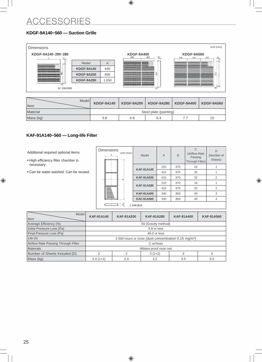
KDGF-9A140~560 — Suction Grille
KAF-91A140~560 — Long-life Filter
Dimensions
3.8
KDGF-9A140
107.76.44.9Mass (kg)
)gnitniap( etalp leetSlairetaM
KDGF-9A560KDGF-9A400KDGF-9A280KDGF-9A200Model
Item
Unit (mm)
KDGF-9A140 200 280 KDGF-9A400 KDGF-9A560
830KDGF-9A200
1,050KDGF-9A280
630KDGF-9A140
AModel
JC: D3K2905
• High efficiency filter chamber is necessary.
• Can be water-washed. Can be reused.
Additional required optional itemsDimensions
340850340KAF-91A400
Model
2
2
1
670
670
670
32410
440850330KAF-91A560
D(Number of
Sheets)
C(Airflow Rate
Passing Through Filter)
B
1
1
16
32
32
16
670
670
210KAF-91A280
410KAF-91A200
410
210KAF-91A140
A
2.0 (1+1)
2
KAF-91A140
433 (1+2)2Number of Sheets Included (D)
50 (Gravity method) Average Efficiency (%)
9.8 or lessInitial Pressure Loss (Pa)
49.0 or lessFinal Pressure Loss (Pa)
2,500 hours or more (dust concentration 0.15 mg/m³)Life (h)
C m³/minAirflow Rate Passing Through Filter
6.04.53.22.4Mass (kg)
ten niser foorp wedliMslairetaM
KAF-91A560KAF-91A400KAF-91A280KAF-91A200Model
Item
Unit (mm)
J: D3K2818
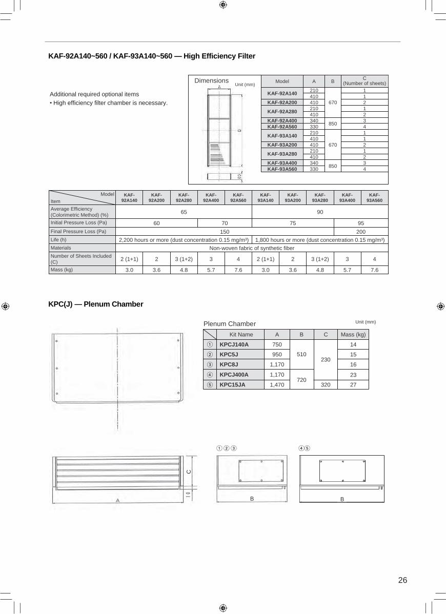
ACCESSORIESKAF-92A140~560 / KAF-93A140~560 — High Efficiency Filter
KPC(J) — Plenum Chamber
• High efficiency filter chamber is necessary.Additional required optional items
Dimensions
3340KAF-93A400
4330KAF-92A560
Model
1
670
210KAF-93A140
14102410KAF-93A20012102410
KAF-93A280
4850
330KAF-93A560
24103
850340KAF-92A400
C(Number of sheets)B
1211
670210
KAF-92A280
410KAF-92A200410210
KAF-92A140
AUnit (mm)
5.7
3
KAF-93A400
3.0
2 (1+1)
KAF-92A140
KAF-92A280
3.6
2
3.6
2
Non-woven fabric of synthetic fiber
2,200 hours or more (dust concentration 0.15 mg/m³)
150
60
65
KAF-92A200
4.8
3 (1+2)
5.7
3
KAF-92A400
7.6
4
70
KAF-92A560
7.6
4
200
95
KAF-93A560
4.8
3 (1+2)
KAF-93A280
KAF-93A200
3.0
2 (1+1)
1,800 hours or more (dust concentration 0.15 mg/m³)
75
90
KAF-93A140
Materials
Life (h)
Number of Sheets Included (C)
Final Pressure Loss (Pa)
Initial Pressure Loss (Pa)
Average Efficiency (Colorimetric Method) (%)
Mass (kg)
ModelItem
B
23
27
16
15
14750
510
720
KPCJ140A
950KPC5J
1,170KPC8J
1,170
1,470
KPCJ400A
KPC15JA
Mass (kg)A B
230
320
CKit Name
Plenum Chamber Unit (mm)
B
C
26
KDGF-9A140~560 — Suction Grille
KAF-91A140~560 — Long-life Filter
Dimensions
3.8
KDGF-9A140
107.76.44.9Mass (kg)
)gnitniap( etalp leetSlairetaM
KDGF-9A560KDGF-9A400KDGF-9A280KDGF-9A200Model
Item
Unit (mm)
KDGF-9A140 200 280 KDGF-9A400 KDGF-9A560
830KDGF-9A200
1,050KDGF-9A280
630KDGF-9A140
AModel
JC: D3K2905
• High efficiency filter chamber is necessary.
• Can be water-washed. Can be reused.
Additional required optional itemsDimensions
340850340KAF-91A400
Model
2
2
1
670
670
670
32410
440850330KAF-91A560
D(Number of
Sheets)
C(Airflow Rate
Passing Through Filter)
B
1
1
16
32
32
16
670
670
210KAF-91A280
410KAF-91A200
410
210KAF-91A140
A
2.0 (1+1)
2
KAF-91A140
433 (1+2)2Number of Sheets Included (D)
50 (Gravity method) Average Efficiency (%)
9.8 or lessInitial Pressure Loss (Pa)
49.0 or lessFinal Pressure Loss (Pa)
2,500 hours or more (dust concentration 0.15 mg/m³)Life (h)
C m³/minAirflow Rate Passing Through Filter
6.04.53.22.4Mass (kg)
ten niser foorp wedliMslairetaM
KAF-91A560KAF-91A400KAF-91A280KAF-91A200Model
Item
Unit (mm)
J: D3K2818
ACCESSORIESKAF-92A140~560 / KAF-93A140~560 — High Efficiency Filter
KPC(J) — Plenum Chamber
• High efficiency filter chamber is necessary.Additional required optional items
Dimensions
3340KAF-93A400
4330KAF-92A560
Model
1
670
210KAF-93A140
14102410KAF-93A20012102410
KAF-93A280
4850
330KAF-93A560
24103
850340KAF-92A400
C(Number of sheets)B
1211
670210
KAF-92A280
410KAF-92A200410210
KAF-92A140
AUnit (mm)
5.7
3
KAF-93A400
3.0
2 (1+1)
KAF-92A140
KAF-92A280
3.6
2
3.6
2
Non-woven fabric of synthetic fiber
2,200 hours or more (dust concentration 0.15 mg/m³)
150
60
65
KAF-92A200
4.8
3 (1+2)
5.7
3
KAF-92A400
7.6
4
70
KAF-92A560
7.6
4
200
95
KAF-93A560
4.8
3 (1+2)
KAF-93A280
KAF-93A200
3.0
2 (1+1)
1,800 hours or more (dust concentration 0.15 mg/m³)
75
90
KAF-93A140
Materials
Life (h)
Number of Sheets Included (C)
Final Pressure Loss (Pa)
Initial Pressure Loss (Pa)
Average Efficiency (Colorimetric Method) (%)
Mass (kg)
ModelItem
B
23
27
16
15
14750
510
720
KPCJ140A
950KPC5J
1,170KPC8J
1,170
1,470
KPCJ400A
KPC15JA
Mass (kg)A B
230
320
CKit Name
Plenum Chamber Unit (mm)
B
C
27
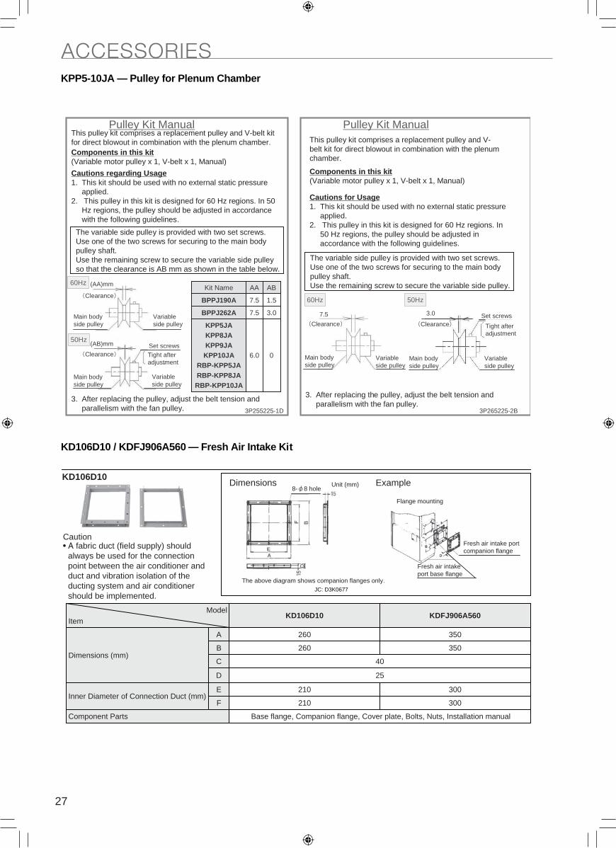
KPP5-10JA — Pulley for Plenum Chamber
KD106D10 / KDFJ906A560 — Fresh Air Intake Kit
0
3.0
1.57.5BPPJ190A
7.5BPPJ262A
6.0
KPP5JAKPP8JAKPP9JAKPP10JA
RBP-KPP5JARBP-KPP8JARBP-KPP10JA
ABAAKit Name
Pulley Kit ManualThis pulley kit comprises a replacement pulley and V-belt kit for direct blowout in combination with the plenum chamber.Components in this kit(Variable motor pulley x 1, V-belt x 1, Manual)
Cautions regarding Usage1. This kit should be used with no external static pressure
applied.2. This pulley in this kit is designed for 60 Hz regions. In 50
Hz regions, the pulley should be adjusted in accordance with the following guidelines.
The variable side pulley is provided with two set screws.Use one of the two screws for securing to the main body pulley shaft.Use the remaining screw to secure the variable side pulley so that the clearance is AB mm as shown in the table below.
(AA)mm
Clearance
Main body side pulley
Variable side pulley
(AB)mm
Main body side pulley
Variable side pulley
Set screws
Pulley Kit ManualThis pulley kit comprises a replacement pulley and V-belt kit for direct blowout in combination with the plenum chamber.
Components in this kit(Variable motor pulley x 1, V-belt x 1, Manual)
Cautions for Usage1. This kit should be used with no external static pressure
applied.2. This pulley in this kit is designed for 60 Hz regions. In
50 Hz regions, the pulley should be adjusted in accordance with the following guidelines.
The variable side pulley is provided with two set screws.Use one of the two screws for securing to the main body pulley shaft.Use the remaining screw to secure the variable side pulley.
7.5
Main body side pulley
Variable side pulley
3.0
Main body side pulley
Variable side pulley
Set screws
3. After replacing the pulley, adjust the belt tension and parallelism with the fan pulley.
3. After replacing the pulley, adjust the belt tension and parallelism with the fan pulley.
B2-522562P3D1-522552P3
Tight after adjustment
Clearance
Clearance Clearance
50Hz
50Hz
60Hz
60Hz
Tight after adjustment
300
300
350
350
012F
E
D
C
B
A
25
210Inner Diameter of Connection Duct (mm)
Base flange, Companion flange, Cover plate, Bolts, Nuts, Installation manualComponent Parts
40
260
260
Dimensions (mm)
KDFJ906A560KD106D10Model
Item
KD106D10
Caution• A fabric duct (field supply) should
always be used for the connection point between the air conditioner and duct and vibration isolation of the ducting system and air conditioner should be implemented.
Dimensions
Fresh air intake port base flange
Fresh air intake port companion flange
The above diagram shows companion flanges only.
Example
Flange mounting
Unit (mm)8- 8 hole
JC: D3K0677
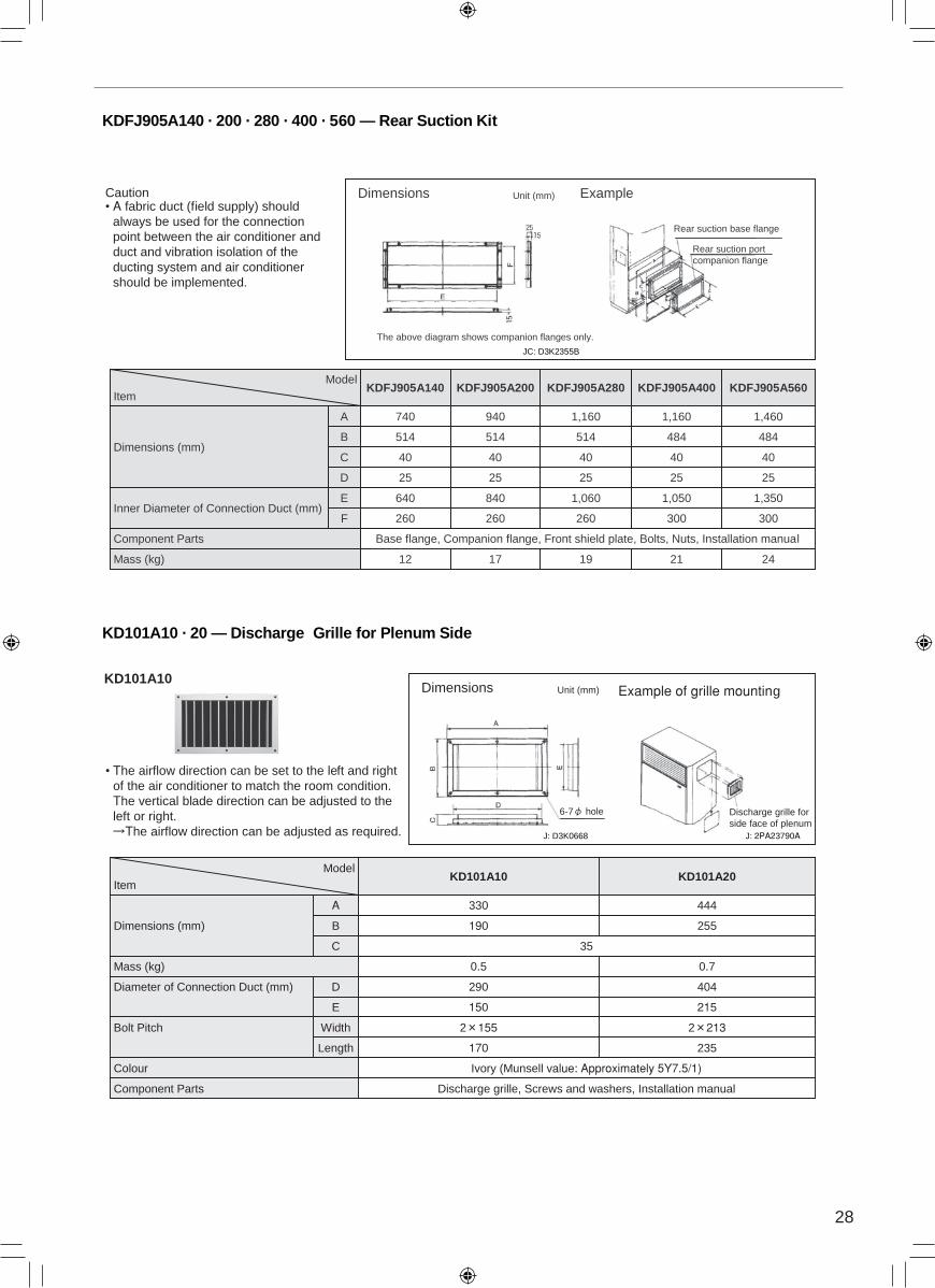
ACCESSORIESKDFJ905A140 · 200 · 280 · 400 · 560 — Rear Suction Kit
KD101A10 · 20 — Discharge Grille for Plenum Side
Dimensions
The above diagram shows companion flanges only.
Example
Rear suction base flange
Rear suction port companion flange
12
260
640
25
40
514
740
KDFJ905A140
242119
Base flange, Companion flange, Front shield plate, Bolts, Nuts, Installation manualComponent Parts
25
40
25
40
260
1,060
25
40
514
1,160
KDFJ905A280
1,350
484
1,460
300
1,050
484
1,160
F 300260
E
D
C
B
A
25
840Inner Diameter of Connection Duct (mm)
17Mass (kg)
40
514
940
Dimensions (mm)
KDFJ905A560KDFJ905A400KDFJ905A200Model
Item
Caution• A fabric duct (field supply) should
always be used for the connection point between the air conditioner and duct and vibration isolation of the ducting system and air conditioner should be implemented.
Unit (mm)
JC: D3K2355B
KD101A10
• The airflow direction can be set to the left and right of the air conditioner to match the room condition.The vertical blade direction can be adjusted to the left or right.
The airflow direction can be adjusted as required.
Dimensions
Discharge grille for side face of plenum
0.70.5Mass (kg)
Ivory (Munsell value: Approximately 5Y7.5/1)Colour
Length
2htdiW 2132 155Bolt Pitch
235170
150
290
190
330
KD101A10
215
404
255
444
E
D
C
B
A
Diameter of Connection Duct (mm)
Discharge grille, Screws and washers, Installation manualComponent Parts
35
Dimensions (mm)
KD101A20Model
Item
Example of grille mountingUnit (mm)
6-7 hole
J: D3K0668 J: 2PA23790A
28
KPP5-10JA — Pulley for Plenum Chamber
KD106D10 / KDFJ906A560 — Fresh Air Intake Kit
0
3.0
1.57.5BPPJ190A
7.5BPPJ262A
6.0
KPP5JAKPP8JAKPP9JAKPP10JA
RBP-KPP5JARBP-KPP8JARBP-KPP10JA
ABAAKit Name
Pulley Kit ManualThis pulley kit comprises a replacement pulley and V-belt kit for direct blowout in combination with the plenum chamber.Components in this kit(Variable motor pulley x 1, V-belt x 1, Manual)
Cautions regarding Usage1. This kit should be used with no external static pressure
applied.2. This pulley in this kit is designed for 60 Hz regions. In 50
Hz regions, the pulley should be adjusted in accordance with the following guidelines.
The variable side pulley is provided with two set screws.Use one of the two screws for securing to the main body pulley shaft.Use the remaining screw to secure the variable side pulley so that the clearance is AB mm as shown in the table below.
(AA)mm
Clearance
Main body side pulley
Variable side pulley
(AB)mm
Main body side pulley
Variable side pulley
Set screws
Pulley Kit ManualThis pulley kit comprises a replacement pulley and V-belt kit for direct blowout in combination with the plenum chamber.
Components in this kit(Variable motor pulley x 1, V-belt x 1, Manual)
Cautions for Usage1. This kit should be used with no external static pressure
applied.2. This pulley in this kit is designed for 60 Hz regions. In
50 Hz regions, the pulley should be adjusted in accordance with the following guidelines.
The variable side pulley is provided with two set screws.Use one of the two screws for securing to the main body pulley shaft.Use the remaining screw to secure the variable side pulley.
7.5
Main body side pulley
Variable side pulley
3.0
Main body side pulley
Variable side pulley
Set screws
3. After replacing the pulley, adjust the belt tension and parallelism with the fan pulley.
3. After replacing the pulley, adjust the belt tension and parallelism with the fan pulley.
B2-522562P3D1-522552P3
Tight after adjustment
Clearance
Clearance Clearance
50Hz
50Hz
60Hz
60Hz
Tight after adjustment
300
300
350
350
012F
E
D
C
B
A
25
210Inner Diameter of Connection Duct (mm)
Base flange, Companion flange, Cover plate, Bolts, Nuts, Installation manualComponent Parts
40
260
260
Dimensions (mm)
KDFJ906A560KD106D10Model
Item
KD106D10
Caution• A fabric duct (field supply) should
always be used for the connection point between the air conditioner and duct and vibration isolation of the ducting system and air conditioner should be implemented.
Dimensions
Fresh air intake port base flange
Fresh air intake port companion flange
The above diagram shows companion flanges only.
Example
Flange mounting
Unit (mm)8- 8 hole
JC: D3K0677
ACCESSORIESKDFJ905A140 · 200 · 280 · 400 · 560 — Rear Suction Kit
KD101A10 · 20 — Discharge Grille for Plenum Side
Dimensions
The above diagram shows companion flanges only.
Example
Rear suction base flange
Rear suction port companion flange
12
260
640
25
40
514
740
KDFJ905A140
242119
Base flange, Companion flange, Front shield plate, Bolts, Nuts, Installation manualComponent Parts
25
40
25
40
260
1,060
25
40
514
1,160
KDFJ905A280
1,350
484
1,460
300
1,050
484
1,160
F 300260
E
D
C
B
A
25
840Inner Diameter of Connection Duct (mm)
17Mass (kg)
40
514
940
Dimensions (mm)
KDFJ905A560KDFJ905A400KDFJ905A200Model
Item
Caution• A fabric duct (field supply) should
always be used for the connection point between the air conditioner and duct and vibration isolation of the ducting system and air conditioner should be implemented.
Unit (mm)
JC: D3K2355B
KD101A10
• The airflow direction can be set to the left and right of the air conditioner to match the room condition.The vertical blade direction can be adjusted to the left or right.
The airflow direction can be adjusted as required.
Dimensions
Discharge grille for side face of plenum
0.70.5Mass (kg)
Ivory (Munsell value: Approximately 5Y7.5/1)Colour
Length
2htdiW 2132 155Bolt Pitch
235170
150
290
190
330
KD101A10
215
404
255
444
E
D
C
B
A
Diameter of Connection Duct (mm)
Discharge grille, Screws and washers, Installation manualComponent Parts
35
Dimensions (mm)
KD101A20Model
Item
Example of grille mountingUnit (mm)
6-7 hole
J: D3K0668 J: 2PA23790A
29
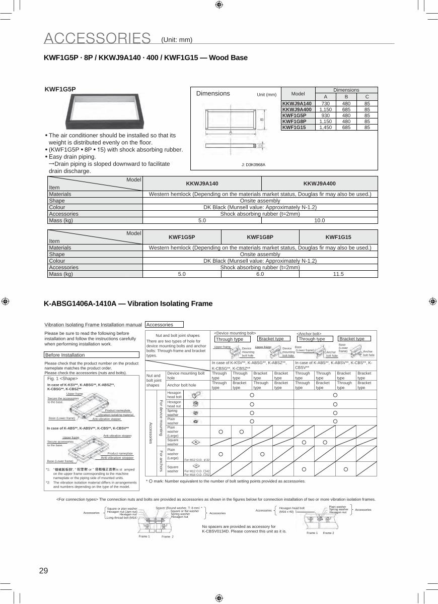
KWF1G5P · 8P / KKWJ9A140 · 400 / KWF1G15 — Wood Base
K-ABSG1406A-1410A — Vibration Isolating Frame
KWF1G5P
• The air conditioner should be installed so that its weight is distributed evenly on the floor.
• (KWF1G5P • 8P • 15) with shock absorbing rubber.• Easy drain piping.
Drain piping is sloped downward to facilitate drain discharge.
Dimensions
854801,150KWF1G8P856851,450KWF1G15
KKWJ9A400480685
85930KWF1G5P
CBDimensions
Model
8585480
1,150730KKWJ9A140A
AccessoriesColourShape
10.0Shock absorbing rubber (t=2mm)
5.0Mass (kg)
DK Black (Munsell value: Approximately N-1.2)Onsite assembly
Western hemlock (Depending on the materials market status, Douglas fir may also be used.)Materials
KKWJ9A400KKWJ9A140Model
Item
11.5
KWF1G15
6.05.0
KWF1G5P
AccessoriesColourShape
Shock absorbing rubber (t=2mm)Mass (kg)
DK Black (Munsell value: Approximately N-1.2)Onsite assembly
Western hemlock (Depending on the materials market status, Douglas fir may also be used.)Materials
KWF1G8PModel
Item
Unit (mm)
J: D3K0968A
Replacement LongReplacement Long --lifelife KAFJ261L140 224 280 KAFJ261M450 560
KAFJ261L140
Can be ater ashed Can be re sed
DimensionsFor M12 O.D. 42For M16 O.D. 52
For M12 O.D. 32
Square washer
Plain washer (Large)
For anchors
Square washer
Plain washer (Large)
Plain washer
Spring washer
Hexagon head nut
Hexagon head boltF
or device mounting
Accessories
Bracket type
Through type
Bracket type
Through type
Bracket type
Through type
Bracket type
Through type
Anchor bolt hole
Bracket type
Bracket type
Through type
Through type
Bracket type
Bracket type
Through type
Through type
Device mounting bolt hole
Nut and bolt joint shapes
In case of K-ABS**, K-ABSV**, K-CBS**, K-CBSV**
In case of K-KSV**, K-ABSG**, K-ABSZ**, K-CBSG**, K-CBSZ**
Nut and bolt joint shapesThere are two types of hole for device mounting bolts and anchor bolts: Through-frame and bracket types.
Vibration Isolating Frame Installation manual
Please be sure to read the following before installation and follow the instructions carefully when performing installation work.
Please check that the product number on the product nameplate matches the product order.Please check the accessories (nuts and bolts).
Before Installation
In case of K-KSV**, K-ABSG**, K-ABSZ**, K-CBSG**, K-CBSZ**
In case of K-ABS**, K-ABSV**, K-CBS**, K-CBSV**
*1:
*2: The vibration isolation material differs in arrangements and numbers depending on the type of the model.
Accessories
" ", " " or " " is st amped on the upper frame corresponding to the machine nameplate or the piping side of mounted units.
<Device mounting bolt>
Through typeUpper frame Device
mounting bolt hole
Bracket type
Device mounting bolt hole
Upper frame
Through type Bracket type
Base(Lower frame) Anchor
bolt hole
Base (Lower frame) Anchor
bolt hole
<Anchor bolt>
* mark: Number equivalent to the number of bolt setting points provided as accessories.
<For connection types> The connection nuts and bolts are provided as accessories as shown in the figures below for connection installation of two or more vibration isolation frames.
AccessoriesSquare or plan washerHexagon nut (Jam nut)
Hexagon nutLong-thread bolt (M16
Spacer (Round washer, T: 8 mm *Square or flat washerSpring washerHexagon nut
AccessoriesAccessories
Plain washerSpring washerHexagon nut
Accessories
No spacers are provided as accessory for K-CBSV0134D. Please connect this unit as it is.
Frame 1 Frame 2Frame 1 Frame 2
Upper frame
Secure the accessories to the base.
Base (Lower frame)
Product nameplate
Vibration isolating materialAnti-vibration stopper
Fig. 1 <Shape>
Anti-vibration stopperUpper frame
Secure accessories to the base.
Base (Lower frame)Anti-vibration stopper
Product nameplate
Hexagon head bolt (M16 x 40)
ACCESSORIES (Unit: mm) ACCESSORIES (Unit: mm)
Dimensions of Optional Accessories
3D083639B
3D083638B 3D083640B
3D083641B
Dimensions of Optional Accessories
FXVQ250NY1FXVQ125NY1
FXVQ400NY1FXVQ200NY1

30
KWF1G5P · 8P / KKWJ9A140 · 400 / KWF1G15 — Wood Base
K-ABSG1406A-1410A — Vibration Isolating Frame
KWF1G5P
• The air conditioner should be installed so that its weight is distributed evenly on the floor.
• (KWF1G5P • 8P • 15) with shock absorbing rubber.• Easy drain piping.
Drain piping is sloped downward to facilitate drain discharge.
Dimensions
854801,150KWF1G8P856851,450KWF1G15
KKWJ9A400480685
85930KWF1G5P
CBDimensions
Model
8585480
1,150730KKWJ9A140A
AccessoriesColourShape
10.0Shock absorbing rubber (t=2mm)
5.0Mass (kg)
DK Black (Munsell value: Approximately N-1.2)Onsite assembly
Western hemlock (Depending on the materials market status, Douglas fir may also be used.)Materials
KKWJ9A400KKWJ9A140Model
Item
11.5
KWF1G15
6.05.0
KWF1G5P
AccessoriesColourShape
Shock absorbing rubber (t=2mm)Mass (kg)
DK Black (Munsell value: Approximately N-1.2)Onsite assembly
Western hemlock (Depending on the materials market status, Douglas fir may also be used.)Materials
KWF1G8PModel
Item
Unit (mm)
J: D3K0968A
Replacement LongReplacement Long --lifelife KAFJ261L140 224 280 KAFJ261M450 560
KAFJ261L140
Can be ater ashed Can be re sed
DimensionsFor M12 O.D. 42For M16 O.D. 52
For M12 O.D. 32
Square washer
Plain washer (Large)
For anchors
Square washer
Plain washer (Large)
Plain washer
Spring washer
Hexagon head nut
Hexagon head boltF
or device mounting
Accessories
Bracket type
Through type
Bracket type
Through type
Bracket type
Through type
Bracket type
Through type
Anchor bolt hole
Bracket type
Bracket type
Through type
Through type
Bracket type
Bracket type
Through type
Through type
Device mounting bolt hole
Nut and bolt joint shapes
In case of K-ABS**, K-ABSV**, K-CBS**, K-CBSV**
In case of K-KSV**, K-ABSG**, K-ABSZ**, K-CBSG**, K-CBSZ**
Nut and bolt joint shapesThere are two types of hole for device mounting bolts and anchor bolts: Through-frame and bracket types.
Vibration Isolating Frame Installation manual
Please be sure to read the following before installation and follow the instructions carefully when performing installation work.
Please check that the product number on the product nameplate matches the product order.Please check the accessories (nuts and bolts).
Before Installation
In case of K-KSV**, K-ABSG**, K-ABSZ**, K-CBSG**, K-CBSZ**
In case of K-ABS**, K-ABSV**, K-CBS**, K-CBSV**
*1:
*2: The vibration isolation material differs in arrangements and numbers depending on the type of the model.
Accessories
" ", " " or " " is st amped on the upper frame corresponding to the machine nameplate or the piping side of mounted units.
<Device mounting bolt>
Through typeUpper frame Device
mounting bolt hole
Bracket type
Device mounting bolt hole
Upper frame
Through type Bracket type
Base(Lower frame) Anchor
bolt hole
Base (Lower frame) Anchor
bolt hole
<Anchor bolt>
* mark: Number equivalent to the number of bolt setting points provided as accessories.
<For connection types> The connection nuts and bolts are provided as accessories as shown in the figures below for connection installation of two or more vibration isolation frames.
AccessoriesSquare or plan washerHexagon nut (Jam nut)
Hexagon nutLong-thread bolt (M16
Spacer (Round washer, T: 8 mm *Square or flat washerSpring washerHexagon nut
AccessoriesAccessories
Plain washerSpring washerHexagon nut
Accessories
No spacers are provided as accessory for K-CBSV0134D. Please connect this unit as it is.
Frame 1 Frame 2Frame 1 Frame 2
Upper frame
Secure the accessories to the base.
Base (Lower frame)
Product nameplate
Vibration isolating materialAnti-vibration stopper
Fig. 1 <Shape>
Anti-vibration stopperUpper frame
Secure accessories to the base.
Base (Lower frame)Anti-vibration stopper
Product nameplate
Hexagon head bolt (M16 x 40)
ACCESSORIES (Unit: mm) ACCESSORIES (Unit: mm)
Dimensions of Optional Accessories
3D083639B
3D083638B 3D083640B
3D083641B
Dimensions of Optional Accessories
FXVQ250NY1FXVQ125NY1
FXVQ400NY1FXVQ200NY1

31
ACCESSORIES (Unit: mm)
Dimensions of Optional Accessories
3D083639B
3D083638B 3D083640B
3D083641B
Dimensions of Optional Accessories
FXVQ250NY1FXVQ125NY1
FXVQ400NY1FXVQ200NY1
Dimensions of Optional Accessories
3D085670A
FXVQ500NY1
ACCESSORIES
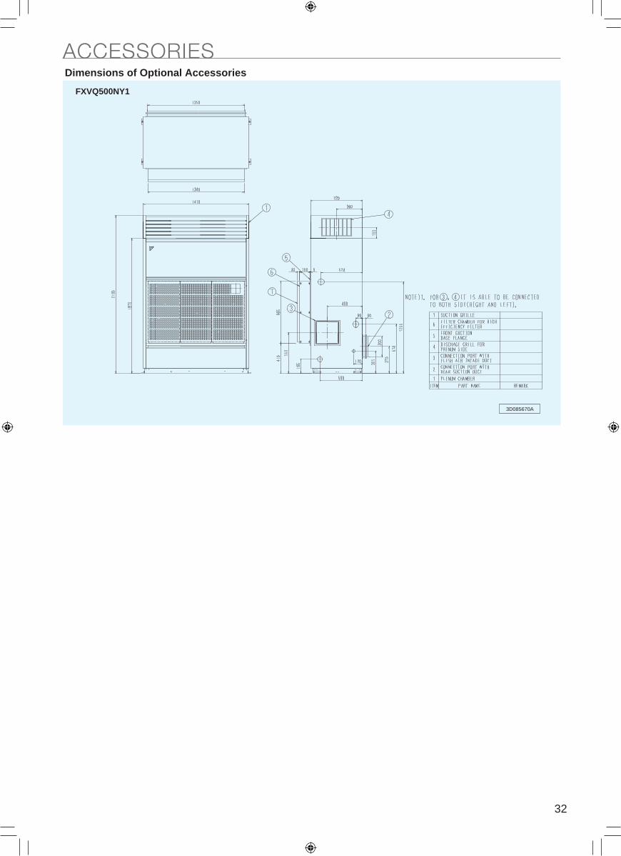
32
ACCESSORIES (Unit: mm)
Dimensions of Optional Accessories
3D083639B
3D083638B 3D083640B
3D083641B
Dimensions of Optional Accessories
FXVQ250NY1FXVQ125NY1
FXVQ400NY1FXVQ200NY1
Dimensions of Optional Accessories
3D085670A
FXVQ500NY1
ACCESSORIES

33
How to Select V beltWhen changing the motor pulley, the standard V belt may not be used.In that case, select V belt in accordance with the following formula:
Note: The unit of V belt length (Nominal number) is usually shown in "inch".
Distance between the shafts of the pulleys (C)
Refer to each Fan Characteristics drawing for the latest value.
Lp : Effective Center Periphery Length (mm)D1: Pitch Diameter of Motor Pulley (mm)D2: Pitch Diameter of Fan Pulley (mm)C : Distance between the shafts of the pulleys (mm)
Unit: mm50Hz
FXVQ125NY1 326
FXVQ200NY1 325
FXVQ250NY1 330
FXVQ400NY1 245
FXVQ500NY1 232
C
Lp
D 1 D 2
Lp = 2C + 1.57 (D1 + D2) + (D2 – D1)
2
4C
Pulley Specification
When using air conditioners in duct connection, external static pressure and airflow rate will increase, exceeding the range of use for standard motors and pulleys. Therefore, it is necessary to change the motor or pulley to deal with this.
3B • 291---- 42
Boss inner diameter (motor shaft diameter: mm)
Pulley outer diameter
B type pulley Takes 3 belts
Pulley outer diameterAt Daikin, the outer diameter is used in pulley sizes.
Pitch Diameter (the actual diameter of the parts in contact with the belt)The pulley makers often use the pitch diameter in pulley sizes.
The pulley makers give the pulley size using the pitch diameter, while Daikin uses the pulley outer diameter.
FAN CHARACTERISTICS (FOR PULLEY SELECTION)Fan Motor Specifications
How to Select Motor Pulley1. Select the fan revolution speed by air flow rate and external static pressure.2. Select Motor Pulley by Fan revolution speed.
Relation between outer diameter and pitch diameter of each Pulley are as follows:A type (Pitch Diameter) = Outer Diameter of Pulley - 9mmB type (Pitch Diameter) = Outer Diameter of Pulley - 11mmPlease use the value given for the fan motor revolution speed (4 pole).50Hz………1450 rpm
ItemsRated motor output 0.75 1.5 2.2 3.7 5.5
Motor
1. Shaft outer diameter φS 19 24 28 28 38
2. Shaft length Q 40 50 60 60 80
3. Keyway width W 6 8 8 8 10
4. Keyway depth U 3.5 4 4 4 5
BEEEEssalc noitalusnI .5
Type A and 1. Shaft hole diameter φd 19 24 28 28 38
018886b yawyeK .2
3. Keyway height h 21.5 27 31 31 41
D1: Pitch Diameter of Motor Pulley (mm)D2: Pitch Diameter of Fan Pulley (mm)N1: Revolution Speed of Fan Motor (rpm)N2: Fan Revolution Speed
V Pulley type B
D1D2 N2
N1
=×
Q W
S
U
ød
b
h
V-belt Size (Length)
Motor pulley
Fan pulley
Fixing nut (A)
Fixing nut (B)
Adjustment nut (C)
Motor pulley
Pulley and Fan Belt Adjustment
Warning Be sure to wait 10 minutes or more after turning off all power supplies before disassembling work.
In case of FXVQ125 / 200 / 250NOperating procedures
Following the installation manual, remove the front panel and others.
Parallelism criteria (K)Less than 10 arc-minutes(discrepancies of 3mm per 1m)
C
L
(1)
Deflection load
L= 0.016 × C (mm)C: Distance between the shafts of the pulleys (mm)
W
Tension of V belt• Tension of a V belt must meet the deflection load (W) as shown.
Calculate the required deflection length (L) by the equation (1), its tolerance must be within the range as below.
Note:• When the new belt is used, adjust the tension to about 1.15 times the deflection load (W) shown above.• When the belt has adopted to the pulley (after operating about 50 hours), adjust the tension to the load shown
above.(Even if the adjustments are made on a new belt, check the load again as shown on the above table after the belt has adopted.)
• With or without replacing the pulley, check the deflection load when about 50 hours passed after the test operation.
• After replacing belt or pulley, conduct the test operation and check if there is no abnormal noise or vibration.
Refer to the JIS B 1854 (Pulley) and JIS K 6323 (V belt) for details. (JIS: Japanese Industrial Standards)
1. Take measurements1) Measure the parallelism of the fan pulley and motor pulley.2) Measure the tension of the fan belt.
2. Make adjustments1) Secure the pulley parallelism by adjustment of the motor pulley position and adjustment of fixing nuts (A) (B).2) Adjust the fan belt tension with adjustment nut (C).
3. Perform checks1) Check that the pulley parallelism and the fan belt tension are within the criteria.
Model V belt Number of belts Motor output (kW) Motor pulley diameter (mm) Deflection load W (N) per
single V belt
FXVQ125-250 Type A
9.9~0.999~57.01
2.31~0.21~40157.01
3.61~8.41511~5.11
2.31~0.21~1212.2 ,5.11

34
How to Select V beltWhen changing the motor pulley, the standard V belt may not be used.In that case, select V belt in accordance with the following formula:
Note: The unit of V belt length (Nominal number) is usually shown in "inch".
Distance between the shafts of the pulleys (C)
Refer to each Fan Characteristics drawing for the latest value.
Lp : Effective Center Periphery Length (mm)D1: Pitch Diameter of Motor Pulley (mm)D2: Pitch Diameter of Fan Pulley (mm)C : Distance between the shafts of the pulleys (mm)
Unit: mm50Hz
FXVQ125NY1 326
FXVQ200NY1 325
FXVQ250NY1 330
FXVQ400NY1 245
FXVQ500NY1 232
C
Lp
D 1 D 2
Lp = 2C + 1.57 (D1 + D2) + (D2 – D1)
2
4C
Pulley Specification
When using air conditioners in duct connection, external static pressure and airflow rate will increase, exceeding the range of use for standard motors and pulleys. Therefore, it is necessary to change the motor or pulley to deal with this.
3B • 291---- 42
Boss inner diameter (motor shaft diameter: mm)
Pulley outer diameter
B type pulley Takes 3 belts
Pulley outer diameterAt Daikin, the outer diameter is used in pulley sizes.
Pitch Diameter (the actual diameter of the parts in contact with the belt)The pulley makers often use the pitch diameter in pulley sizes.
The pulley makers give the pulley size using the pitch diameter, while Daikin uses the pulley outer diameter.
FAN CHARACTERISTICS (FOR PULLEY SELECTION)Fan Motor Specifications
How to Select Motor Pulley1. Select the fan revolution speed by air flow rate and external static pressure.2. Select Motor Pulley by Fan revolution speed.
Relation between outer diameter and pitch diameter of each Pulley are as follows:A type (Pitch Diameter) = Outer Diameter of Pulley - 9mmB type (Pitch Diameter) = Outer Diameter of Pulley - 11mmPlease use the value given for the fan motor revolution speed (4 pole).50Hz………1450 rpm
ItemsRated motor output 0.75 1.5 2.2 3.7 5.5
Motor
1. Shaft outer diameter φS 19 24 28 28 38
2. Shaft length Q 40 50 60 60 80
3. Keyway width W 6 8 8 8 10
4. Keyway depth U 3.5 4 4 4 5
BEEEEssalc noitalusnI .5
Type A and 1. Shaft hole diameter φd 19 24 28 28 38
018886b yawyeK .2
3. Keyway height h 21.5 27 31 31 41
D1: Pitch Diameter of Motor Pulley (mm)D2: Pitch Diameter of Fan Pulley (mm)N1: Revolution Speed of Fan Motor (rpm)N2: Fan Revolution Speed
V Pulley type B
D1D2 N2
N1
=×
Q W
S
U
ød
b
h
V-belt Size (Length)
Motor pulley
Fan pulley
Fixing nut (A)
Fixing nut (B)
Adjustment nut (C)
Motor pulley
Pulley and Fan Belt Adjustment
Warning Be sure to wait 10 minutes or more after turning off all power supplies before disassembling work.
In case of FXVQ125 / 200 / 250NOperating procedures
Following the installation manual, remove the front panel and others.
Parallelism criteria (K)Less than 10 arc-minutes(discrepancies of 3mm per 1m)
C
L
(1)
Deflection load
L= 0.016 × C (mm)C: Distance between the shafts of the pulleys (mm)
W
Tension of V belt• Tension of a V belt must meet the deflection load (W) as shown.
Calculate the required deflection length (L) by the equation (1), its tolerance must be within the range as below.
Note:• When the new belt is used, adjust the tension to about 1.15 times the deflection load (W) shown above.• When the belt has adopted to the pulley (after operating about 50 hours), adjust the tension to the load shown
above.(Even if the adjustments are made on a new belt, check the load again as shown on the above table after the belt has adopted.)
• With or without replacing the pulley, check the deflection load when about 50 hours passed after the test operation.
• After replacing belt or pulley, conduct the test operation and check if there is no abnormal noise or vibration.
Refer to the JIS B 1854 (Pulley) and JIS K 6323 (V belt) for details. (JIS: Japanese Industrial Standards)
1. Take measurements1) Measure the parallelism of the fan pulley and motor pulley.2) Measure the tension of the fan belt.
2. Make adjustments1) Secure the pulley parallelism by adjustment of the motor pulley position and adjustment of fixing nuts (A) (B).2) Adjust the fan belt tension with adjustment nut (C).
3. Perform checks1) Check that the pulley parallelism and the fan belt tension are within the criteria.
Model V belt Number of belts Motor output (kW) Motor pulley diameter (mm) Deflection load W (N) per
single V belt
FXVQ125-250 Type A
9.9~0.999~57.01
2.31~0.21~40157.01
3.61~8.41511~5.11
2.31~0.21~1212.2 ,5.11
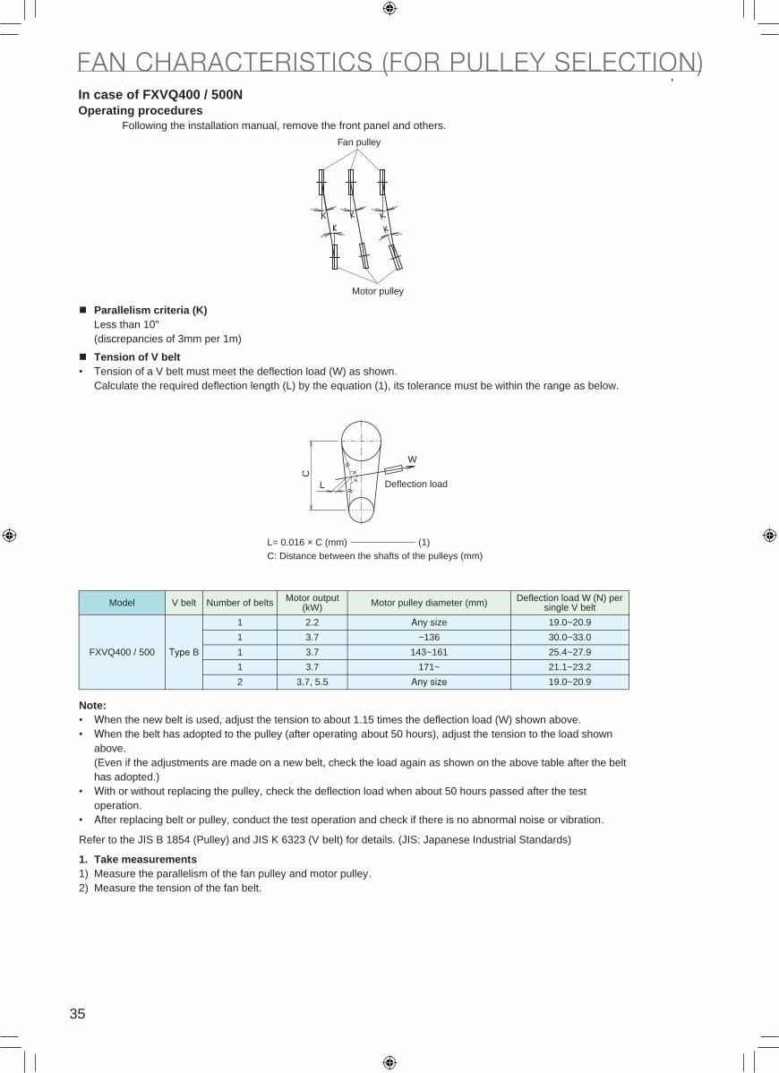
35
FAN CHARACTERISTICS (FOR PULLEY SELECTION)In case of FXVQ400 / 500NOperating procedures
Following the installation manual, remove the front panel and others.
Parallelism criteria (K)Less than 10"(discrepancies of 3mm per 1m)
Tension of V belt• Tension of a V belt must meet the deflection load (W) as shown.
Calculate the required deflection length (L) by the equation (1), its tolerance must be within the range as below.
Note:• When the new belt is used, adjust the tension to about 1.15 times the deflection load (W) shown above.• When the belt has adopted to the pulley (after operating about 50 hours), adjust the tension to the load shown
above.(Even if the adjustments are made on a new belt, check the load again as shown on the above table after the belt has adopted.)
• With or without replacing the pulley, check the deflection load when about 50 hours passed after the test operation.
• After replacing belt or pulley, conduct the test operation and check if there is no abnormal noise or vibration.
Refer to the JIS B 1854 (Pulley) and JIS K 6323 (V belt) for details. (JIS: Japanese Industrial Standards)
1. Take measurements1) Measure the parallelism of the fan pulley and motor pulley.2) Measure the tension of the fan belt.
Model V belt Number of belts Motor output (kW) Motor pulley diameter (mm) Deflection load W (N) per
single V belt
FXVQ400 / 500 Type B
9.02~0.91ezis ynA2.21
1 3.7 ~136 30.0~33.0
1 3.7 143~161 25.4~27.9
1 3.7 171~ 21.1~23.2
2 3.7, 5.5 Any size 19.0~20.9
Fan pulley
Motor pulleyC
L
(1)
Deflection load
L= 0.016 × C (mm)C: Distance between the shafts of the pulleys (mm)
W
2. Make adjustments1) Secure the pulley parallelism by adjustment of the motor pulley position and adjustment of fixing bolt (A).2) Adjust the fan belt tension by loosening fixing bolt (A) and using adjustment nut (B), (C).
3. Perform checks1) Check that the pulley parallelism and the fan belt tension are within the criteria.
V Belt Size TableRefer to the JIS K 6323 (V belt) for details. (JIS: Japanese Industrial Standards)
(Unit: mm)Nominal number Type A Type B Nominal
number Type A Type B Nominal number Type A Type B Nominal
number Type A Type B
20 508 — 49 1245 1245 78 1981 1981 118 2997 2997
21 533 — 50 1270 1270 79 2007 2007 120 3048 3048
22 559 — 51 1295 1295 80 2032 2032 122 3099 3099
23 584 — 52 1321 1321 81 2057 2057 125 3175 3175
24 610 — 53 1346 1346 82 2083 2083 128 3251 3251
25 635 635 54 1372 1372 83 2108 2108 130 3302 3302
26 660 660 55 1397 1397 84 2134 2134 132 — 3353
27 686 686 56 1422 1422 85 2159 2159 135 3429 3429
28 711 711 57 1448 1448 86 2184 2184 138 — 3505
29 737 737 58 1473 1473 87 2210 2210 140 3556 3556
30 762 762 59 1499 1499 88 2235 2235 142 — —
31 787 787 60 1524 1524 89 2261 2261 145 3683 3683
32 813 813 61 1549 1549 90 2286 2286 148 — —
33 838 838 62 1575 1575 91 2311 2311 150 3810 3810
34 864 864 63 1600 1600 92 2337 2337 155 3937 3937
35 889 889 64 1626 1626 93 2362 2362 160 4064 4064
36 914 914 65 1651 1651 94 2388 2388 165 4191 4191
37 940 940 66 1676 1676 95 2413 2413 170 4318 4318
38 965 965 67 1702 1702 96 2438 2438 175 — 4445
39 991 991 68 1727 1727 97 2464 2464 180 4572 4572
40 1016 1016 69 1753 1753 98 2489 2489 185 — 4699
41 1041 1041 70 1778 1778 99 2515 2515 190 — 4826
42 1067 1067 71 1803 1803 100 2540 2540 195 — 4953
43 1092 1092 72 1829 1829 102 2591 2591 200 — 5080
44 1118 1118 73 1854 1854 105 2667 2667 210 — 5334
45 1143 1143 74 1880 1880 108 2743 2743
46 1168 1168 75 1905 1905 110 2794 2794
47 1194 1194 76 1930 1930 112 2845 2845
48 1219 1219 77 1956 1956 115 2921 2921
Adjustment nut (C)
Adjustment nut (B)
Fixing bolt (A)

36
FAN CHARACTERISTICS (FOR PULLEY SELECTION)In case of FXVQ400 / 500NOperating procedures
Following the installation manual, remove the front panel and others.
Parallelism criteria (K)Less than 10"(discrepancies of 3mm per 1m)
Tension of V belt• Tension of a V belt must meet the deflection load (W) as shown.
Calculate the required deflection length (L) by the equation (1), its tolerance must be within the range as below.
Note:• When the new belt is used, adjust the tension to about 1.15 times the deflection load (W) shown above.• When the belt has adopted to the pulley (after operating about 50 hours), adjust the tension to the load shown
above.(Even if the adjustments are made on a new belt, check the load again as shown on the above table after the belt has adopted.)
• With or without replacing the pulley, check the deflection load when about 50 hours passed after the test operation.
• After replacing belt or pulley, conduct the test operation and check if there is no abnormal noise or vibration.
Refer to the JIS B 1854 (Pulley) and JIS K 6323 (V belt) for details. (JIS: Japanese Industrial Standards)
1. Take measurements1) Measure the parallelism of the fan pulley and motor pulley.2) Measure the tension of the fan belt.
Model V belt Number of belts Motor output (kW) Motor pulley diameter (mm) Deflection load W (N) per
single V belt
FXVQ400 / 500 Type B
9.02~0.91ezis ynA2.21
1 3.7 ~136 30.0~33.0
1 3.7 143~161 25.4~27.9
1 3.7 171~ 21.1~23.2
2 3.7, 5.5 Any size 19.0~20.9
Fan pulley
Motor pulley
C
L
(1)
Deflection load
L= 0.016 × C (mm)C: Distance between the shafts of the pulleys (mm)
W
2. Make adjustments1) Secure the pulley parallelism by adjustment of the motor pulley position and adjustment of fixing bolt (A).2) Adjust the fan belt tension by loosening fixing bolt (A) and using adjustment nut (B), (C).
3. Perform checks1) Check that the pulley parallelism and the fan belt tension are within the criteria.
V Belt Size TableRefer to the JIS K 6323 (V belt) for details. (JIS: Japanese Industrial Standards)
(Unit: mm)Nominal number Type A Type B Nominal
number Type A Type B Nominal number Type A Type B Nominal
number Type A Type B
20 508 — 49 1245 1245 78 1981 1981 118 2997 2997
21 533 — 50 1270 1270 79 2007 2007 120 3048 3048
22 559 — 51 1295 1295 80 2032 2032 122 3099 3099
23 584 — 52 1321 1321 81 2057 2057 125 3175 3175
24 610 — 53 1346 1346 82 2083 2083 128 3251 3251
25 635 635 54 1372 1372 83 2108 2108 130 3302 3302
26 660 660 55 1397 1397 84 2134 2134 132 — 3353
27 686 686 56 1422 1422 85 2159 2159 135 3429 3429
28 711 711 57 1448 1448 86 2184 2184 138 — 3505
29 737 737 58 1473 1473 87 2210 2210 140 3556 3556
30 762 762 59 1499 1499 88 2235 2235 142 — —
31 787 787 60 1524 1524 89 2261 2261 145 3683 3683
32 813 813 61 1549 1549 90 2286 2286 148 — —
33 838 838 62 1575 1575 91 2311 2311 150 3810 3810
34 864 864 63 1600 1600 92 2337 2337 155 3937 3937
35 889 889 64 1626 1626 93 2362 2362 160 4064 4064
36 914 914 65 1651 1651 94 2388 2388 165 4191 4191
37 940 940 66 1676 1676 95 2413 2413 170 4318 4318
38 965 965 67 1702 1702 96 2438 2438 175 — 4445
39 991 991 68 1727 1727 97 2464 2464 180 4572 4572
40 1016 1016 69 1753 1753 98 2489 2489 185 — 4699
41 1041 1041 70 1778 1778 99 2515 2515 190 — 4826
42 1067 1067 71 1803 1803 100 2540 2540 195 — 4953
43 1092 1092 72 1829 1829 102 2591 2591 200 — 5080
44 1118 1118 73 1854 1854 105 2667 2667 210 — 5334
45 1143 1143 74 1880 1880 108 2743 2743
46 1168 1168 75 1905 1905 110 2794 2794
47 1194 1194 76 1930 1930 112 2845 2845
48 1219 1219 77 1956 1956 115 2921 2921
Adjustment nut (C)
Adjustment nut (B)
Fixing bolt (A)
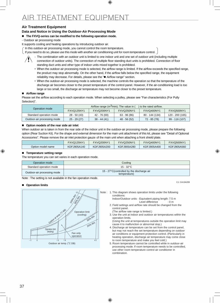
37
AIR TREATMENT EQUIPMENT
Temperature setting rangeThe temperature you can set varies in each operation mode.
Note : The setting is not available in the fan operation mode. CJ: CA13A209
Operation limits
Cooling edom noitarepO
15 - 32°Cedom noitarepo dradnatS
Outdoor-air processing mode 15 - 27°C(controlled by the discharge air temperature)
Outdoor air te
mp. (˚C W
B)
100%
RH
90%
RH
30% RH
20% RH
Operation limit(heating)
Operation limit(cooling)
Note : 1. This diagram shows operation limits under the following conditions:Indoor/Outdoor units - Equivalent piping length: 7.5 m
Level difference : 0 m2. Field settings and airflow rate should be changed from the
control panel.(The airflow rate range is limited.)
3. Use the unit at indoor and outdoor air temperatures within the operation limits.(Using the unit at temperatures outside the operation limit may cause it to malfunction or abnormal stop.)
4. Discharge air temperature can be set from the control panel, but may not reach the set temperature depending on outdoor air conditions or equipment protection control. (Particularly in heating operation, discharge air temperature may come close to room temperature and make you feel cold.)
5. Room temperature cannot be controlled while in outdoor-air processing mode. If room temperature needs to be controlled, use other room temperature control air conditioner in combination.
Outdoor air temp. (˚C DB)
Fan only operation
Data and Notice in Using the Outdoor-Air Processing Mode The FXVQ-series can be modified to the following operation mode.
- Outdoor air processing mode It supports cooling and heating operations by introducing outdoor air.
Airflow rangePlease set the airflow according to each operation mode. When selecting a pulley, please see "Fan characteristics (For Pully Selection)".
Option models of the rear side air inletWhen outdoor air is taken in from the rear side of the indoor unit in the outdoor-air processing mode, please prepare the following option (Rear Suction Kit). For the shape and external dimension for the main unit attachment of this kit, please see "Detail of Optional Accessories". Please remove the air inlet protection gauze of the main unit when attaching a front shield plate.
In this outdoor-air processing mode, you cannot control the room temperature. If you need to do so, please use this mode with another air conditioning unit for room temperature control.
Operation modeAirflow range (m3/min); The value in ( ) is the rated airflow.
Standard operation mode
Outdoor-air processing mode
Option model name
- The combination with an outdoor unit is limited to one indoor unit and one set of outdoor unit (including multiple connection of outdoor units). The connection of multiple floor standing duct units is prohibited. Connection of floor standing duct units and other type of indoor units mixed together is prohibited.
• When the outdoor-air processing mode is selected, the airflow range is limited. If the airflow exceeds the specified range, the product may stop abnormally. On the other hand, if the airflow falls below the specified range, the equipment reliability may decrease. For details, please see the " Airflow range" section.
• When the outdoor-air processing mode is selected, the machine controls the operation so that the temperature of the discharge air becomes closer to the preset temperature of the control panel. However, if the air-conditioning load is too large or too small, the discharge air temperature may not become closer to the preset temperature.
FXVQ125NY1
28 - 50 (43)
25 - 29 (27)
FXVQ125NY1
KDFJ905A140
FXVQ200NY1
KDFJ905A200
FXVQ250NY1
KDFJ905A280
FXVQ400NY1
KDFJ905A400
FXVQ500NY1
KDFJ905A560
FXVQ500NY1
120 - 200 (165)
99 - 116 (107)
FXVQ200NY1
42 - 76 (69)
38 - 44 (41)
FXVQ250NY1
63 - 96 (86)
48 - 56 (52)
FXVQ400NY1
80 - 144 (134)
72 - 85 (78)
Air Treatment Equipment Field settings[In case of VRV IV]Be sure to set from both (a) Field settings from the indoor unit and (b) Field settings from the outdoor unit.
(a) Field settings from the indoor unitYou need to configure the settings by the control panel of the indoor unit to change the operation mode. Please configure the settings as shown below after completing test run.Please also see the installation manual of the indoor unit for the setting method.
(b) Field settings from the outdoor unit Perform field settings with push button switch (BS1-3) on the Printed Circuit Board in the Electric Component Box.After finishing check operation, set up according to following procedure.As to setting method, refer to the paragraph of Field Setting in the installation manual of the outdoor unit as well.
Operation mode Mode No. First code No. Second code No.
Standard operation mode841
01
Outdoor-air processing mode 03
Procedure of outdoor-air processing mode setting Details of setting7 Segment display
SEG1 SEG2 SEG3
1. Push the new page button (BS1) for 5 seconds in normal mode. Confirm that 7 segment display is same as the figure shown in the right.
Switched to Setting mode. 2 0 0
2. Push the operation button (BS2) and adjust the 7 segment display to the figure shown in the right. "Outdoor-air processing mode" 2 9 3
3. Push the confirmation button (BS3). The present settings of [4.] will be indicated.
4. Push the operation button (BS2) and adjust the 7 segment display to the figure shown in the right.
"Invalid" (factory set) light off light off 0
1ffo thgilffo thgil"dilaV"
gnittes ehT.)3SB( nottub noitamrifnoc eht hsuP .5 in [4.] is defined. It will turn to light ON.
6. Push the confirmation button (BS3) again. The system starts the operation according to the setting. 2 0 0
ffo thgilffo thgilffo thgil.edom lamroN ot denruteR.)1SB( nottub egap wen eht hsuP .7
[In case of VRV III]Set from (a) Field settings from the indoor unit only.
(a) Field settings from the indoor unitYou need to configure the settings by the control panel of the indoor unit to change the operation mode. Please configure the settings as shown below after completing test run.Please also see the installation manual of the indoor unit for the setting method.
Specification table (outdoor-air processing mode)
Note : 1Indoor temperature: 33°CDB, 28°CWB / outdoor temperature: 33°CDB / Equivalent piping length: 7.5 m, level difference: 0 m.
2This product is shipped with the airflow set to the standard mode. When introducing outdoor air (outdoor-air processing mode), please make sure to adjust the air flow by conducting field settings from the control panel, changing the pulley, or installing dampers. If not adjusting the airflow, the airflow would still be set to the standard mode and therefore you might feel cold when heating or feel hot when cooling.
3The value is the external static pressure with standard pulley.
Model name
Cooling capacity 1 kW
FanAirflow rate 2 m3/min
External static pressure 3 Pa
FXVQ125NY1
14.0
27
120
FXVQ200NY1
22.4
41
150
FXVQ250NY1
28.0
52
120
FXVQ400NY1
45.0
78
261
FXVQ500NY1
56.0
107
175
First code No. Second code No.Operation mode Mode No.
Standard operation mode841
01
Outdoor-air processing mode 03

38
AIR TREATMENT EQUIPMENT
Temperature setting rangeThe temperature you can set varies in each operation mode.
Note : The setting is not available in the fan operation mode. CJ: CA13A209
Operation limits
Cooling edom noitarepO
15 - 32°Cedom noitarepo dradnatS
Outdoor-air processing mode 15 - 27°C(controlled by the discharge air temperature)
Outdoor air te
mp. (˚C W
B)
100%
RH
90%
RH
30% RH
20% RH
Operation limit(heating)
Operation limit(cooling)
Note : 1. This diagram shows operation limits under the following conditions:Indoor/Outdoor units - Equivalent piping length: 7.5 m
Level difference : 0 m2. Field settings and airflow rate should be changed from the
control panel.(The airflow rate range is limited.)
3. Use the unit at indoor and outdoor air temperatures within the operation limits.(Using the unit at temperatures outside the operation limit may cause it to malfunction or abnormal stop.)
4. Discharge air temperature can be set from the control panel, but may not reach the set temperature depending on outdoor air conditions or equipment protection control. (Particularly in heating operation, discharge air temperature may come close to room temperature and make you feel cold.)
5. Room temperature cannot be controlled while in outdoor-air processing mode. If room temperature needs to be controlled, use other room temperature control air conditioner in combination.
Outdoor air temp. (˚C DB)
Fan only operation
Data and Notice in Using the Outdoor-Air Processing Mode The FXVQ-series can be modified to the following operation mode.
- Outdoor air processing mode It supports cooling and heating operations by introducing outdoor air.
Airflow rangePlease set the airflow according to each operation mode. When selecting a pulley, please see "Fan characteristics (For Pully Selection)".
Option models of the rear side air inletWhen outdoor air is taken in from the rear side of the indoor unit in the outdoor-air processing mode, please prepare the following option (Rear Suction Kit). For the shape and external dimension for the main unit attachment of this kit, please see "Detail of Optional Accessories". Please remove the air inlet protection gauze of the main unit when attaching a front shield plate.
In this outdoor-air processing mode, you cannot control the room temperature. If you need to do so, please use this mode with another air conditioning unit for room temperature control.
Operation modeAirflow range (m3/min); The value in ( ) is the rated airflow.
Standard operation mode
Outdoor-air processing mode
Option model name
- The combination with an outdoor unit is limited to one indoor unit and one set of outdoor unit (including multiple connection of outdoor units). The connection of multiple floor standing duct units is prohibited. Connection of floor standing duct units and other type of indoor units mixed together is prohibited.
• When the outdoor-air processing mode is selected, the airflow range is limited. If the airflow exceeds the specified range, the product may stop abnormally. On the other hand, if the airflow falls below the specified range, the equipment reliability may decrease. For details, please see the " Airflow range" section.
• When the outdoor-air processing mode is selected, the machine controls the operation so that the temperature of the discharge air becomes closer to the preset temperature of the control panel. However, if the air-conditioning load is too large or too small, the discharge air temperature may not become closer to the preset temperature.
FXVQ125NY1
28 - 50 (43)
25 - 29 (27)
FXVQ125NY1
KDFJ905A140
FXVQ200NY1
KDFJ905A200
FXVQ250NY1
KDFJ905A280
FXVQ400NY1
KDFJ905A400
FXVQ500NY1
KDFJ905A560
FXVQ500NY1
120 - 200 (165)
99 - 116 (107)
FXVQ200NY1
42 - 76 (69)
38 - 44 (41)
FXVQ250NY1
63 - 96 (86)
48 - 56 (52)
FXVQ400NY1
80 - 144 (134)
72 - 85 (78)
Air Treatment Equipment Field settings[In case of VRV IV]Be sure to set from both (a) Field settings from the indoor unit and (b) Field settings from the outdoor unit.
(a) Field settings from the indoor unitYou need to configure the settings by the control panel of the indoor unit to change the operation mode. Please configure the settings as shown below after completing test run.Please also see the installation manual of the indoor unit for the setting method.
(b) Field settings from the outdoor unit Perform field settings with push button switch (BS1-3) on the Printed Circuit Board in the Electric Component Box.After finishing check operation, set up according to following procedure.As to setting method, refer to the paragraph of Field Setting in the installation manual of the outdoor unit as well.
Operation mode Mode No. First code No. Second code No.
Standard operation mode841
01
Outdoor-air processing mode 03
Procedure of outdoor-air processing mode setting Details of setting7 Segment display
SEG1 SEG2 SEG3
1. Push the new page button (BS1) for 5 seconds in normal mode. Confirm that 7 segment display is same as the figure shown in the right.
Switched to Setting mode. 2 0 0
2. Push the operation button (BS2) and adjust the 7 segment display to the figure shown in the right. "Outdoor-air processing mode" 2 9 3
3. Push the confirmation button (BS3). The present settings of [4.] will be indicated.
4. Push the operation button (BS2) and adjust the 7 segment display to the figure shown in the right.
"Invalid" (factory set) light off light off 0
1ffo thgilffo thgil"dilaV"
gnittes ehT.)3SB( nottub noitamrifnoc eht hsuP .5 in [4.] is defined. It will turn to light ON.
6. Push the confirmation button (BS3) again. The system starts the operation according to the setting. 2 0 0
ffo thgilffo thgilffo thgil.edom lamroN ot denruteR.)1SB( nottub egap wen eht hsuP .7
[In case of VRV III]Set from (a) Field settings from the indoor unit only.
(a) Field settings from the indoor unitYou need to configure the settings by the control panel of the indoor unit to change the operation mode. Please configure the settings as shown below after completing test run.Please also see the installation manual of the indoor unit for the setting method.
Specification table (outdoor-air processing mode)
Note : 1Indoor temperature: 33°CDB, 28°CWB / outdoor temperature: 33°CDB / Equivalent piping length: 7.5 m, level difference: 0 m.
2This product is shipped with the airflow set to the standard mode. When introducing outdoor air (outdoor-air processing mode), please make sure to adjust the air flow by conducting field settings from the control panel, changing the pulley, or installing dampers. If not adjusting the airflow, the airflow would still be set to the standard mode and therefore you might feel cold when heating or feel hot when cooling.
3The value is the external static pressure with standard pulley.
Model name
Cooling capacity 1 kW
FanAirflow rate 2 m3/min
External static pressure 3 Pa
FXVQ125NY1
14.0
27
120
FXVQ200NY1
22.4
41
150
FXVQ250NY1
28.0
52
120
FXVQ400NY1
45.0
78
261
FXVQ500NY1
56.0
107
175
First code No. Second code No.Operation mode Mode No.
Standard operation mode841
01
Outdoor-air processing mode 03
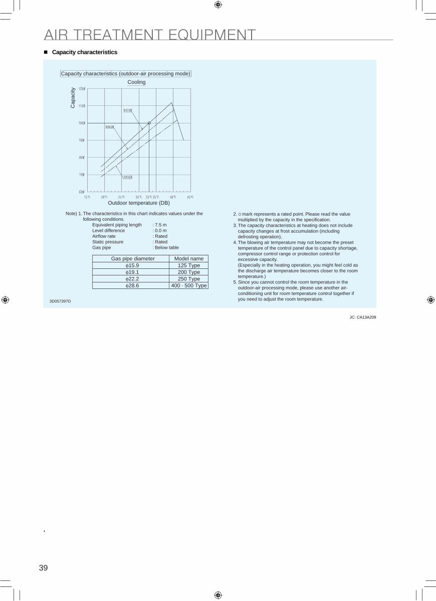
39
AIR TREATMENT EQUIPMENTCapacity characteristics
JC: CA13A209
Gas pipe diameter Model nameφ15.9φ19.1φ22.2φ28.6
125 Type200 Type250 Type
400 · 500 Type
Capacity characteristics (outdoor-air processing mode)
Cooling
Cap
acity
)BD( erutarepmet roodtuO
Note) 1. The characteristics in this chart indicates values under the following conditions.
Equivalent piping length : 7.5 mLevel difference : 0.0 mAirflow rate : RatedStatic pressure : RatedGas pipe : Below table
2. mark represents a rated point. Please read the value multiplied by the capacity in the specification.
3. The capacity characteristics at heating does not include capacity changes at frost accumulation (including defrosting operation).
4. The blowing air temperature may not become the preset temperature of the control panel due to capacity shortage, compressor control range or protection control for excessive capacity.(Especially in the heating operation, you might feel cold as the discharge air temperature becomes closer to the room temperature.)
5. Since you cannot control the room temperature in the outdoor-air processing mode, please use another air-conditioning unit for room temperature control together if you need to adjust the room temperature.3D057397D
2
3P345056-6E
1 English
CONTENTS
1. SAFETY PRECAUTIONS ................................................. 1
2. BEFORE INSTALLATION ................................................. 2
3. CARRY-IN METHOD ........................................................ 3
4. INSTALLATION SITE ....................................................... 3
5. CAUTION AT INSTALLATION .......................................... 4
6. REFRIGERANT PIPING ................................................... 4
7. DRAIN PIPING ................................................................. 6
8. ELECTRIC WIRING.......................................................... 6
9. FIELD SETTING AND CONTROL WIRING ......................... 9
10. TRIAL OPERATION .............................................................10
1. SAFETY PRECAUTIONS
Be sure to follow this “SAFETY PRECAUTIONS”.
This product comes under the term “appliances not
accessible to the general public”.
This is a class A product. In a domestic environment this
product may cause radio interference in which case the user
may be required to take adequate measures.
CAUTIONS.
Be sure to follow all the precautions below: They are all
important for ensuring safety.
WARNING ......... Indicates a potentially hazardous
situation which, if not avoided, could
result in death or serious injury.
CAUTION .......... Indicates a potentially hazardous
situation which, if not avoided, may
result in minor or moderate injury.
It may also be used to alert against
unsafe practices.
After the installation is completed, test the air conditioner
and check if the air conditioner operates properly. Give
the user adequate instructions concerning the use and
cleaning of the indoor unit according to the Operation
Manual. Ask the user to keep this manual and the
Operation Manual together in a handy place for future
reference.
WARNING
installation work.
Improper installation may result in water leakage, electric
Perform installation work in accordance with this installation
manual.
Improper installation may result in water leakage, electric
Consult your local dealer regarding what to do in case of
refrigerant leakage.
When the air conditioner is installed in a small room, it is
necessary to take proper measures so that the amount of
any leaked refrigerant does not exceed the concentration
limit in the event of a leakage.
Otherwise, this may lead to an accident due to oxygen
installation work.
conditioner falling down, water leakage, electric shocks, a
Install the air conditioner on a foundation that can
withstand its mass.
It may lead to vibration of indoor units and cause
unpleasant chattering noise.
strong winds, typhoons, or earthquakes.
Improper installation may result in an accident such as air
conditioner falling.
Make certain that all electrical work is carried out by
(note 1) and this installation manual, using a separate
circuit.
In addition, even if the wiring is short, make sure to use
(note 1) applicable legislation means “All international,
national and local directives, laws, regulations and/
or codes which are relevant and applicable for a
certain product or domain”.
Earth the air conditioner.
Do not connect the earth wiring to gas or water piping,
lightning conductor or telephone earth wiring.
Be sure to install an earth leakage circuit breaker.
Disconnect the power supply before touching the electric
components.
If you touch the live part, you may get an electric shocks.
wiring and ensuring that external forces do not act on the
terminal connections or wiring.
When wiring between the indoor and outdoor units, and
wiring the power supply, form the wiring orderly so that the
control box lid can be securely fastened.
If the control box lid is not in place, overheat of the
If refrigerant gas leaks during installation work, ventilate
the area immediately.
Toxic gas may be produced if refrigerant gas comes into
After completing the installation work, check to make sure
that there is no leakage of refrigerant gas.
Toxic gas may be produced if refrigerant gas leaks into the
as a fan heater, stove or cooker.
Never directly touch any accidental leaking refrigerant.
This could result in severe wounds caused by frostbite.
CAUTION
Install drain piping according to this installation manual to
ensure good drainage, and insulate the piping to prevent
condensation.
Improper drain piping may cause water leakage, make the
furniture get wet.
Installation
manualVRV System
air conditionerFXVQ125NY1 FXVQ200NY1 FXVQ250NY1 FXVQ400NY1 FXVQ500NY1
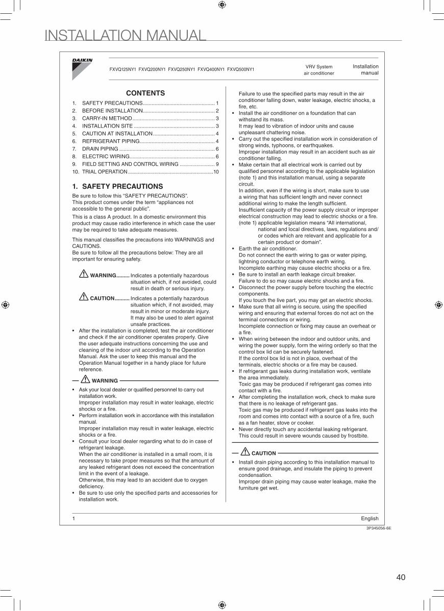
40
AIR TREATMENT EQUIPMENTCapacity characteristics
JC: CA13A209
Gas pipe diameter Model nameφ15.9φ19.1φ22.2φ28.6
125 Type200 Type250 Type
400 · 500 Type
Capacity characteristics (outdoor-air processing mode)
Cooling
Cap
acity
)BD( erutarepmet roodtuO
Note) 1. The characteristics in this chart indicates values under the following conditions.
Equivalent piping length : 7.5 mLevel difference : 0.0 mAirflow rate : RatedStatic pressure : RatedGas pipe : Below table
2. mark represents a rated point. Please read the value multiplied by the capacity in the specification.
3. The capacity characteristics at heating does not include capacity changes at frost accumulation (including defrosting operation).
4. The blowing air temperature may not become the preset temperature of the control panel due to capacity shortage, compressor control range or protection control for excessive capacity.(Especially in the heating operation, you might feel cold as the discharge air temperature becomes closer to the room temperature.)
5. Since you cannot control the room temperature in the outdoor-air processing mode, please use another air-conditioning unit for room temperature control together if you need to adjust the room temperature.3D057397D
2
3P345056-6E
1 English
CONTENTS
1. SAFETY PRECAUTIONS ................................................. 1
2. BEFORE INSTALLATION ................................................. 2
3. CARRY-IN METHOD ........................................................ 3
4. INSTALLATION SITE ....................................................... 3
5. CAUTION AT INSTALLATION .......................................... 4
6. REFRIGERANT PIPING ................................................... 4
7. DRAIN PIPING ................................................................. 6
8. ELECTRIC WIRING.......................................................... 6
9. FIELD SETTING AND CONTROL WIRING ......................... 9
10. TRIAL OPERATION .............................................................10
1. SAFETY PRECAUTIONS
Be sure to follow this “SAFETY PRECAUTIONS”.
This product comes under the term “appliances not
accessible to the general public”.
This is a class A product. In a domestic environment this
product may cause radio interference in which case the user
may be required to take adequate measures.
CAUTIONS.
Be sure to follow all the precautions below: They are all
important for ensuring safety.
WARNING ......... Indicates a potentially hazardous
situation which, if not avoided, could
result in death or serious injury.
CAUTION .......... Indicates a potentially hazardous
situation which, if not avoided, may
result in minor or moderate injury.
It may also be used to alert against
unsafe practices.
After the installation is completed, test the air conditioner
and check if the air conditioner operates properly. Give
the user adequate instructions concerning the use and
cleaning of the indoor unit according to the Operation
Manual. Ask the user to keep this manual and the
Operation Manual together in a handy place for future
reference.
WARNING
installation work.
Improper installation may result in water leakage, electric
Perform installation work in accordance with this installation
manual.
Improper installation may result in water leakage, electric
Consult your local dealer regarding what to do in case of
refrigerant leakage.
When the air conditioner is installed in a small room, it is
necessary to take proper measures so that the amount of
any leaked refrigerant does not exceed the concentration
limit in the event of a leakage.
Otherwise, this may lead to an accident due to oxygen
installation work.
conditioner falling down, water leakage, electric shocks, a
Install the air conditioner on a foundation that can
withstand its mass.
It may lead to vibration of indoor units and cause
unpleasant chattering noise.
strong winds, typhoons, or earthquakes.
Improper installation may result in an accident such as air
conditioner falling.
Make certain that all electrical work is carried out by
(note 1) and this installation manual, using a separate
circuit.
In addition, even if the wiring is short, make sure to use
(note 1) applicable legislation means “All international,
national and local directives, laws, regulations and/
or codes which are relevant and applicable for a
certain product or domain”.
Earth the air conditioner.
Do not connect the earth wiring to gas or water piping,
lightning conductor or telephone earth wiring.
Be sure to install an earth leakage circuit breaker.
Disconnect the power supply before touching the electric
components.
If you touch the live part, you may get an electric shocks.
wiring and ensuring that external forces do not act on the
terminal connections or wiring.
When wiring between the indoor and outdoor units, and
wiring the power supply, form the wiring orderly so that the
control box lid can be securely fastened.
If the control box lid is not in place, overheat of the
If refrigerant gas leaks during installation work, ventilate
the area immediately.
Toxic gas may be produced if refrigerant gas comes into
After completing the installation work, check to make sure
that there is no leakage of refrigerant gas.
Toxic gas may be produced if refrigerant gas leaks into the
as a fan heater, stove or cooker.
Never directly touch any accidental leaking refrigerant.
This could result in severe wounds caused by frostbite.
CAUTION
Install drain piping according to this installation manual to
ensure good drainage, and insulate the piping to prevent
condensation.
Improper drain piping may cause water leakage, make the
furniture get wet.
Installation
manualVRV System
air conditionerFXVQ125NY1 FXVQ200NY1 FXVQ250NY1 FXVQ400NY1 FXVQ500NY1
INSTALLATION MANUAL
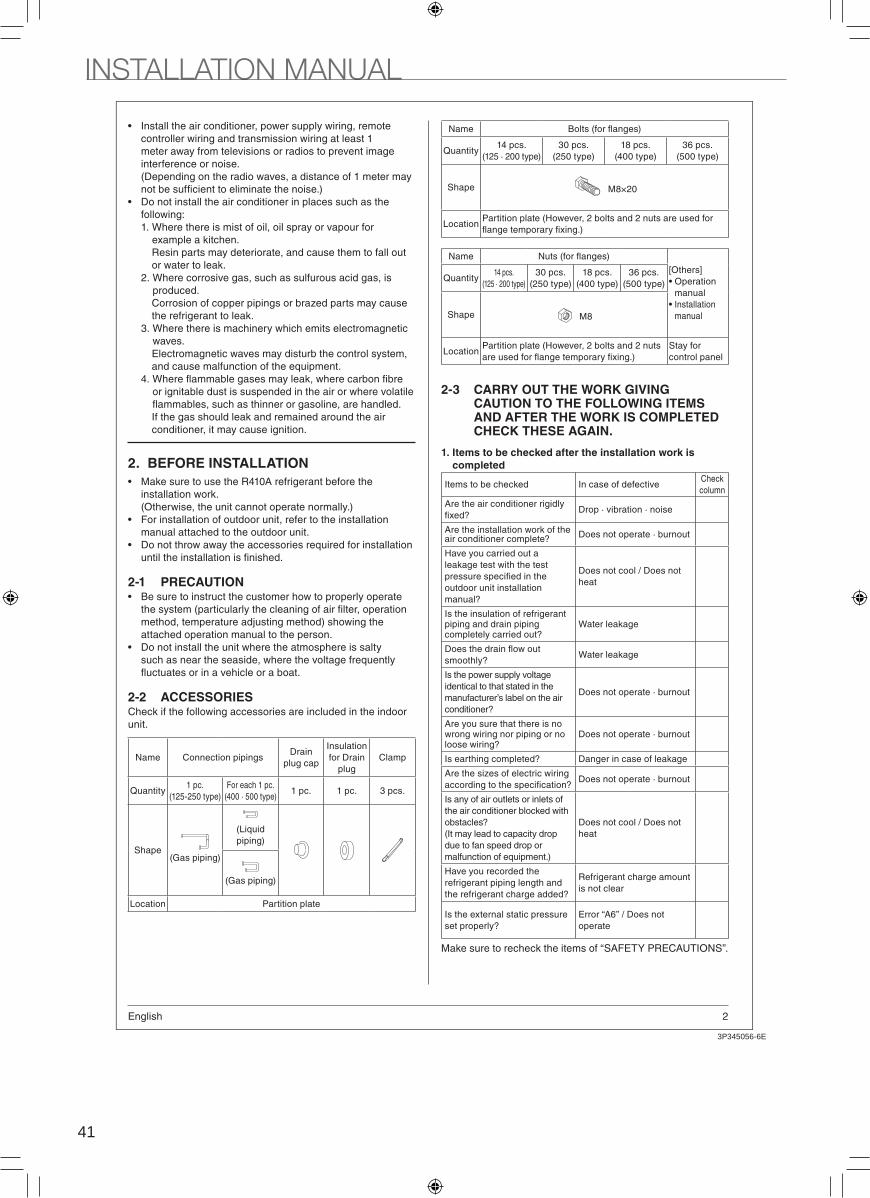
41
3P345056-6E
2English
Install the air conditioner, power supply wiring, remote
controller wiring and transmission wiring at least 1
meter away from televisions or radios to prevent image
interference or noise.
(Depending on the radio waves, a distance of 1 meter may
Do not install the air conditioner in places such as the
following:
1. Where there is mist of oil, oil spray or vapour for
example a kitchen.
Resin parts may deteriorate, and cause them to fall out
or water to leak.
2. Where corrosive gas, such as sulfurous acid gas, is
produced.
Corrosion of copper pipings or brazed parts may cause
the refrigerant to leak.
3. Where there is machinery which emits electromagnetic
waves.
Electromagnetic waves may disturb the control system,
and cause malfunction of the equipment.
or ignitable dust is suspended in the air or where volatile
If the gas should leak and remained around the air
conditioner, it may cause ignition.
2. BEFORE INSTALLATION
Make sure to use the R410A refrigerant before the
installation work.
(Otherwise, the unit cannot operate normally.)
For installation of outdoor unit, refer to the installation
manual attached to the outdoor unit.
Do not throw away the accessories required for installation
2-1 PRECAUTIONBe sure to instruct the customer how to properly operate
method, temperature adjusting method) showing the
attached operation manual to the person.
Do not install the unit where the atmosphere is salty
such as near the seaside, where the voltage frequently
2-2 ACCESSORIESCheck if the following accessories are included in the indoor
unit.
Name Connection pipingsDrain
plug cap
Insulation
for Drain
plug
Clamp
Quantity1 pc.
(125-250 type)
For each 1 pc.
(400 · 500 type)1 pc. 1 pc. 3 pcs.
Shape(Gas piping)
(Liquid
piping)
(Gas piping)
Location Partition plate
Name
Quantity14 pcs.
(125 · 200 type)
30 pcs.
(250 type)
18 pcs.
(400 type)
36 pcs.
(500 type)
Shape M8×20
LocationPartition plate (However, 2 bolts and 2 nuts are used for
Name
[Others]
Operation
manual
Installation
manual
Quantity14 pcs.
(125 · 200 type)
30 pcs.
(250 type)
18 pcs.
(400 type)
36 pcs.
(500 type)
Shape M8
LocationPartition plate (However, 2 bolts and 2 nuts Stay for
control panel
2-3 CARRY OUT THE WORK GIVING CAUTION TO THE FOLLOWING ITEMS AND AFTER THE WORK IS COMPLETED CHECK THESE AGAIN.
1. Items to be checked after the installation work is
completed
Items to be checked In case of defectiveCheck
column
Are the air conditioner rigidly Drop · vibration · noise
Are the installation work of the Does not operate · burnout
Have you carried out a
leakage test with the test
outdoor unit installation
Does not cool / Does not
heat
Is the insulation of refrigerant piping and drain piping Water leakage
Water leakage
Is the power supply voltage
identical to that stated in the
manufacturer’s label on the air Does not operate · burnout
Are you sure that there is no wrong wiring nor piping or no Does not operate · burnout
Danger in case of leakage
Are the sizes of electric wiring Does not operate · burnout
Is any of air outlets or inlets of
the air conditioner blocked with
(It may lead to capacity drop
due to fan speed drop or
malfunction of equipment.)
Does not cool / Does not
heat
Have you recorded the
refrigerant piping length and Refrigerant charge amount
is not clear
Is the external static pressure Error “A6” / Does not
operate
Make sure to recheck the items of “SAFETY PRECAUTIONS”.
2
3P345056-6E
3 English
2. Items to be checked at delivery
Items to be checkedCheck
column
Does the cool air discharge during the cooling
operation and the warm air discharge during heating
Have you explained how to operate the air conditioner
Have you explained the description of cooling and
Have you handed the operation manual and the
Points of the operation explanation
In addition to the general usage, since the items in the
operation manual with the WARNING and CAUTION
marks are likely to result in human bodily injuries and
property damages, it is necessary not only to explain
these items to the customer but also to have the
customer read them.
It is also necessary to explain the items of “NOT
MALFUNCTION OF THE AIR CONDITIONER” to the
customer and have the customer read them carefully.
3. CARRY-IN METHOD
Note
Do not throw away the accessories required for installation
Choose the carry-in route of the indoor unit.
When lifting the unit with a crane, use belt sling and
Belt slingPut a rag or a corrugated
the suction grille and the control
4. INSTALLATION SITE
Note
Do not apply force on the resin parts in case of carrying the
indoor unit when and after unpacking.
(1) Select an installation site where the following conditions
installation.
The foundation is strong enough to support the weight
noise generation.
The place where the cold (warm) air is spread all over
the room.
(In case of free blow by the plenum chamber)
The place where the condensate can be properly
drained.
gas leak.
The place where is not heat affected by other heating
equipment.
The space around the unit is adequate for servicing
and the minimum space for air inlet and air outlet is
available.
The place where the piping length between indoor unit
and outdoor unit is within the allowable limit.
(Refer to the installation manual attached to the
outdoor unit.)
(2) After installation, remove the shipping brackets attached
to the bottom frame.
(3) Secure the unit to its base using foundation bolts.
4-1 EXAMPLE OF REQUIRED SPACE
to local space in view of walkway and ventilation when
installing.
Piping connection A B
Left side 500 mm 100 mm
Right side 100 mm 500 mm
(4 Portions)
(125- )
( )
900 mm or more
A or more B or more
Indoor
unit
10
0 m
m
or
mo
re
<Front
side>
INSTALLATION MANUAL
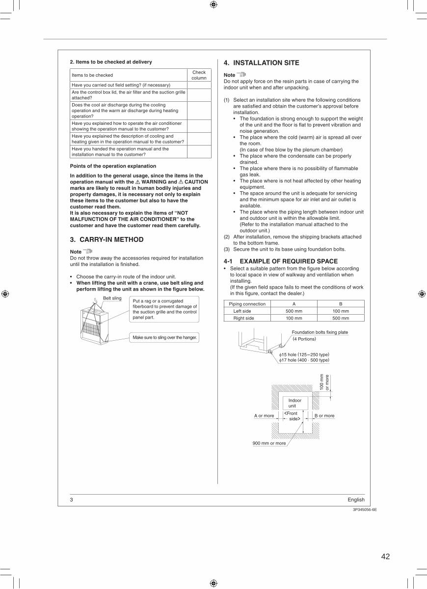
42
3P345056-6E
2English
Install the air conditioner, power supply wiring, remote
controller wiring and transmission wiring at least 1
meter away from televisions or radios to prevent image
interference or noise.
(Depending on the radio waves, a distance of 1 meter may
Do not install the air conditioner in places such as the
following:
1. Where there is mist of oil, oil spray or vapour for
example a kitchen.
Resin parts may deteriorate, and cause them to fall out
or water to leak.
2. Where corrosive gas, such as sulfurous acid gas, is
produced.
Corrosion of copper pipings or brazed parts may cause
the refrigerant to leak.
3. Where there is machinery which emits electromagnetic
waves.
Electromagnetic waves may disturb the control system,
and cause malfunction of the equipment.
or ignitable dust is suspended in the air or where volatile
If the gas should leak and remained around the air
conditioner, it may cause ignition.
2. BEFORE INSTALLATION
Make sure to use the R410A refrigerant before the
installation work.
(Otherwise, the unit cannot operate normally.)
For installation of outdoor unit, refer to the installation
manual attached to the outdoor unit.
Do not throw away the accessories required for installation
2-1 PRECAUTIONBe sure to instruct the customer how to properly operate
method, temperature adjusting method) showing the
attached operation manual to the person.
Do not install the unit where the atmosphere is salty
such as near the seaside, where the voltage frequently
2-2 ACCESSORIESCheck if the following accessories are included in the indoor
unit.
Name Connection pipingsDrain
plug cap
Insulation
for Drain
plug
Clamp
Quantity1 pc.
(125-250 type)
For each 1 pc.
(400 · 500 type)1 pc. 1 pc. 3 pcs.
Shape(Gas piping)
(Liquid
piping)
(Gas piping)
Location Partition plate
Name
Quantity14 pcs.
(125 · 200 type)
30 pcs.
(250 type)
18 pcs.
(400 type)
36 pcs.
(500 type)
Shape M8×20
LocationPartition plate (However, 2 bolts and 2 nuts are used for
Name
[Others]
Operation
manual
Installation
manual
Quantity14 pcs.
(125 · 200 type)
30 pcs.
(250 type)
18 pcs.
(400 type)
36 pcs.
(500 type)
Shape M8
LocationPartition plate (However, 2 bolts and 2 nuts Stay for
control panel
2-3 CARRY OUT THE WORK GIVING CAUTION TO THE FOLLOWING ITEMS AND AFTER THE WORK IS COMPLETED CHECK THESE AGAIN.
1. Items to be checked after the installation work is
completed
Items to be checked In case of defectiveCheck
column
Are the air conditioner rigidly Drop · vibration · noise
Are the installation work of the Does not operate · burnout
Have you carried out a
leakage test with the test
outdoor unit installation
Does not cool / Does not
heat
Is the insulation of refrigerant piping and drain piping Water leakage
Water leakage
Is the power supply voltage
identical to that stated in the
manufacturer’s label on the air Does not operate · burnout
Are you sure that there is no wrong wiring nor piping or no Does not operate · burnout
Danger in case of leakage
Are the sizes of electric wiring Does not operate · burnout
Is any of air outlets or inlets of
the air conditioner blocked with
(It may lead to capacity drop
due to fan speed drop or
malfunction of equipment.)
Does not cool / Does not
heat
Have you recorded the
refrigerant piping length and Refrigerant charge amount
is not clear
Is the external static pressure Error “A6” / Does not
operate
Make sure to recheck the items of “SAFETY PRECAUTIONS”.
2
3P345056-6E
3 English
2. Items to be checked at delivery
Items to be checkedCheck
column
Does the cool air discharge during the cooling
operation and the warm air discharge during heating
Have you explained how to operate the air conditioner
Have you explained the description of cooling and
Have you handed the operation manual and the
Points of the operation explanation
In addition to the general usage, since the items in the
operation manual with the WARNING and CAUTION
marks are likely to result in human bodily injuries and
property damages, it is necessary not only to explain
these items to the customer but also to have the
customer read them.
It is also necessary to explain the items of “NOT
MALFUNCTION OF THE AIR CONDITIONER” to the
customer and have the customer read them carefully.
3. CARRY-IN METHOD
Note
Do not throw away the accessories required for installation
Choose the carry-in route of the indoor unit.
When lifting the unit with a crane, use belt sling and
Belt slingPut a rag or a corrugated
the suction grille and the control
4. INSTALLATION SITE
Note
Do not apply force on the resin parts in case of carrying the
indoor unit when and after unpacking.
(1) Select an installation site where the following conditions
installation.
The foundation is strong enough to support the weight
noise generation.
The place where the cold (warm) air is spread all over
the room.
(In case of free blow by the plenum chamber)
The place where the condensate can be properly
drained.
gas leak.
The place where is not heat affected by other heating
equipment.
The space around the unit is adequate for servicing
and the minimum space for air inlet and air outlet is
available.
The place where the piping length between indoor unit
and outdoor unit is within the allowable limit.
(Refer to the installation manual attached to the
outdoor unit.)
(2) After installation, remove the shipping brackets attached
to the bottom frame.
(3) Secure the unit to its base using foundation bolts.
4-1 EXAMPLE OF REQUIRED SPACE
to local space in view of walkway and ventilation when
installing.
Piping connection A B
Left side 500 mm 100 mm
Right side 100 mm 500 mm
(4 Portions)
(125- )
( )
900 mm or more
A or more B or more
Indoor
unit
10
0 m
m
or
mo
re
<Front
side>
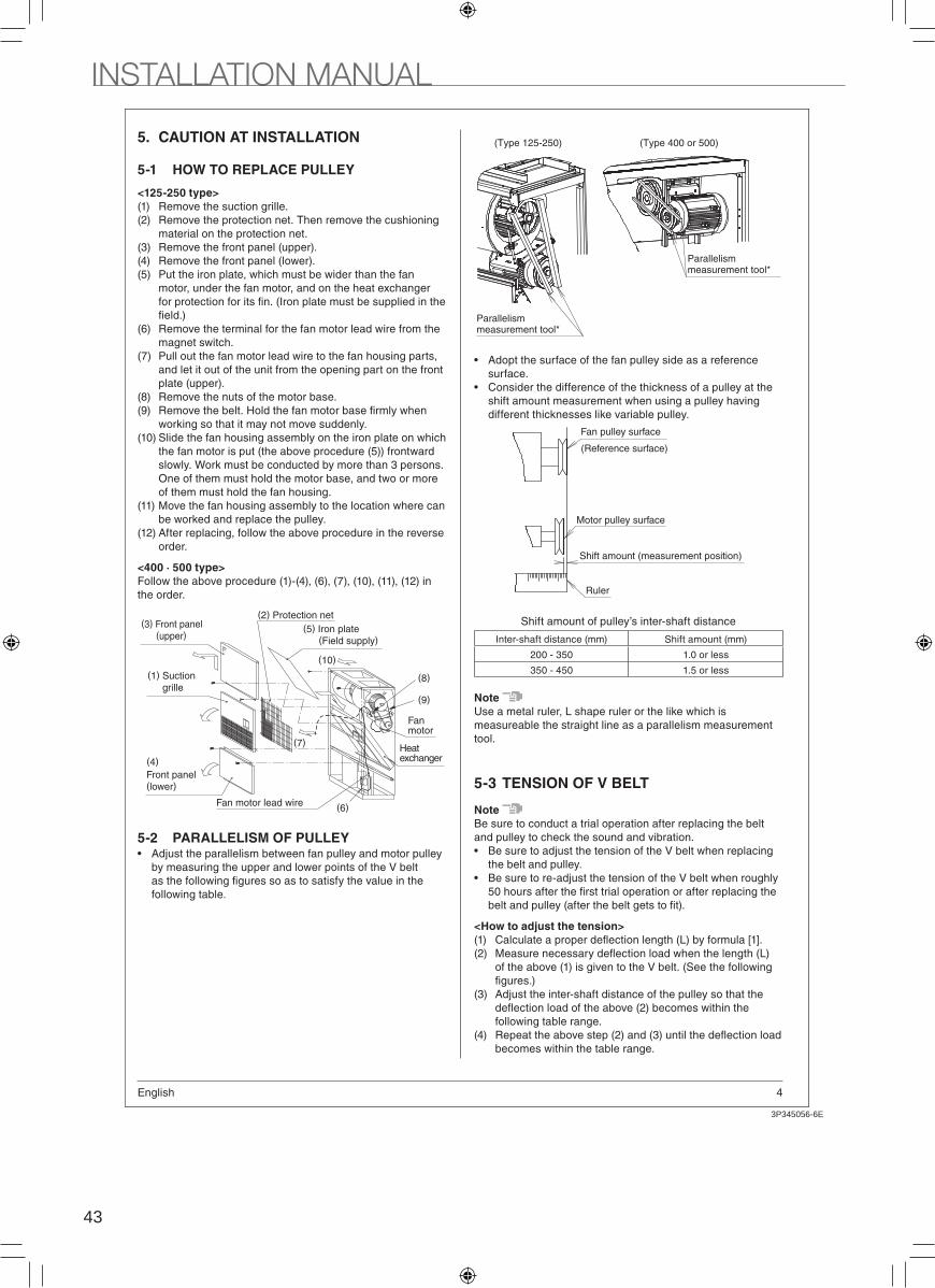
43
3P345056-6E
4English
5. CAUTION AT INSTALLATION
5-1 HOW TO REPLACE PULLEY
<125-250 type>
(1) Remove the suction grille.
(2) Remove the protection net. Then remove the cushioning
material on the protection net.
(3) Remove the front panel (upper).
(4) Remove the front panel (lower).
(5) Put the iron plate, which must be wider than the fan
motor, under the fan motor, and on the heat exchanger
(6) Remove the terminal for the fan motor lead wire from the
magnet switch.
(7) Pull out the fan motor lead wire to the fan housing parts,
and let it out of the unit from the opening part on the front
plate (upper).
(8) Remove the nuts of the motor base.
(9)
working so that it may not move suddenly.
(10) Slide the fan housing assembly on the iron plate on which
the fan motor is put (the above procedure (5)) frontward
slowly. Work must be conducted by more than 3 persons.
One of them must hold the motor base, and two or more
of them must hold the fan housing.
(11) Move the fan housing assembly to the location where can
be worked and replace the pulley.
(12) After replacing, follow the above procedure in the reverse
order.
<400 · 500 type>
Follow the above procedure (1)-(4), (6), (7), (10), (11), (12) in
the order.
(7)
(6)
(8)
(10)
(9)
(4)
Fan motor lead wire
(5) Iron plate(Field supply)
(2) Protection net(3) Front panel
(upper)
(1) Suction
grille
Front panel (lower)
Fan motor
Heat exchanger
5-2 PARALLELISM OF PULLEYAdjust the parallelism between fan pulley and motor pulley
by measuring the upper and lower points of the V belt
following table.
(Type 125-250) (Type 400 or 500)
Parallelism measurement tool*
Parallelism measurement tool*
Adopt the surface of the fan pulley side as a reference
surface.
Consider the difference of the thickness of a pulley at the
shift amount measurement when using a pulley having
different thicknesses like variable pulley.
Fan pulley surface
Motor pulley surface
Shift amount (measurement position)
Ruler
(Reference surface)
Shift amount of pulley’s inter-shaft distance
Inter-shaft distance (mm) Shift amount (mm)
200 - 350 1.0 or less
350 - 450 1.5 or less
Note
Use a metal ruler, L shape ruler or the like which is
measureable the straight line as a parallelism measurement
tool.
5-3 TENSION OF V BELT
Note
Be sure to conduct a trial operation after replacing the belt
and pulley to check the sound and vibration.
Be sure to adjust the tension of the V belt when replacing
the belt and pulley.
Be sure to re-adjust the tension of the V belt when roughly
<How to adjust the tension>
(1)
(2)
of the above (1) is given to the V belt. (See the following
(3) Adjust the inter-shaft distance of the pulley so that the
following table range.
(4)
becomes within the table range.
2
3P345056-6E
5 English
(Type 125-250)
Tension meter
(Type 400 or 500)
Tension meter
tension meter vertically to the midpoint of the belt until it
C L
L=0.016×C [1]
Note
initial tensioning when the belt is renewed.
Belt type QtyMotor output
(kW)
Motor pulley
diameter (mm) W (N) per belt
A
1 0.75 - 99 9.0 – 9.9
1 0.75 104 - 12.0 – 13.2
1 1.5 - 115 14.8 – 16.3
1 1.5, 2.2 121 - 12.0 – 13.2
B
1 2.2 Any 19.0 – 20.9
1 3.7 - 136 30.0 – 33.0
1 3.7 143 - 161 25.4 – 27.9
1 3.7 171 - 21.1 – 23.2
2 3.7, 5.5 Any 19.0 – 20.9
6. REFRIGERANT PIPING
For the refrigerant piping of the outdoor unit, refer to the
installation manual attached to the outdoor unit.
Make sure to use R410A as refrigerant before the
installation work. (Otherwise, the unit cannot operate
normally)
Make sure to insulate the piping on both the liquid side and
the gas side. Otherwise, water leakage may be caused.
120 °C. Reinforce the refrigerant piping according to the
installation environment. Otherwise, condensation may
form on the surface of the insulation.
CAUTION
This unit is for using R410A only.
Make sure to follow the items as shown in below when
working.
exclusively used for R410A.
Protect the piping by a pinch or taping to prevent invasion
of contamination, moisture and dusts into the piping.
6-1 MATERIAL OF PIPINGUse the copper tube according to the following table.
Indoor unit
capacity
Piping size
Piping on gas side Piping on liquid side
125 type 15.9 × t1.0 mm 9.5 × t0.8 mm
200 type 19.1 × t1.0 mm 9.5 × t0.8 mm
250 type 22.2 × t1.0 mm 9.5 × t0.8 mm
400 type 28.6 × t1.0 mm 12.7 × t0.8 mm
500 type 28.6 × t1.0 mm 15.9 × t1.0 mm
6-2 HOW TO WORK THE REFRIGERANT PIPING
Remove the pinched pipings brazed to the end of the internal
piping.
Braze and connect the standard accessory piping.
Connection pipings
Do not directly
Do not directly
6-3 PIPING CONNECTION
CAUTION
Do not use anti-oxidants when brazing the piping joints.
Residue can clog pipings and break equipment.
Be sure to perform a nitrogen blow when brazing
Brazing without performing nitrogen replacement or
releasing nitrogen into the piping will create large
adversely affecting valves and compressors in the
refrigerating system and preventing normal operation.
Note
For nitrogen replacement, refer to the installation work
manual. (Contact the dealer.)
pressure to 0.02 MPa or less using a pressure reducing
valve (to the extent that your cheeks feel breeze).
phosphor copper brazing (BCup-2: JIS Z 3264/B-Cu93P-710
/795: ISO 3677
lubricant to deteriorate, adversely affecting the
refrigerant piping system.
( )
( )
INSTALLATION MANUAL

44
3P345056-6E
4English
5. CAUTION AT INSTALLATION
5-1 HOW TO REPLACE PULLEY
<125-250 type>
(1) Remove the suction grille.
(2) Remove the protection net. Then remove the cushioning
material on the protection net.
(3) Remove the front panel (upper).
(4) Remove the front panel (lower).
(5) Put the iron plate, which must be wider than the fan
motor, under the fan motor, and on the heat exchanger
(6) Remove the terminal for the fan motor lead wire from the
magnet switch.
(7) Pull out the fan motor lead wire to the fan housing parts,
and let it out of the unit from the opening part on the front
plate (upper).
(8) Remove the nuts of the motor base.
(9)
working so that it may not move suddenly.
(10) Slide the fan housing assembly on the iron plate on which
the fan motor is put (the above procedure (5)) frontward
slowly. Work must be conducted by more than 3 persons.
One of them must hold the motor base, and two or more
of them must hold the fan housing.
(11) Move the fan housing assembly to the location where can
be worked and replace the pulley.
(12) After replacing, follow the above procedure in the reverse
order.
<400 · 500 type>
Follow the above procedure (1)-(4), (6), (7), (10), (11), (12) in
the order.
(7)
(6)
(8)
(10)
(9)
(4)
Fan motor lead wire
(5) Iron plate(Field supply)
(2) Protection net(3) Front panel
(upper)
(1) Suction
grille
Front panel (lower)
Fan motor
Heat exchanger
5-2 PARALLELISM OF PULLEYAdjust the parallelism between fan pulley and motor pulley
by measuring the upper and lower points of the V belt
following table.
(Type 125-250) (Type 400 or 500)
Parallelism measurement tool*
Parallelism measurement tool*
Adopt the surface of the fan pulley side as a reference
surface.
Consider the difference of the thickness of a pulley at the
shift amount measurement when using a pulley having
different thicknesses like variable pulley.
Fan pulley surface
Motor pulley surface
Shift amount (measurement position)
Ruler
(Reference surface)
Shift amount of pulley’s inter-shaft distance
Inter-shaft distance (mm) Shift amount (mm)
200 - 350 1.0 or less
350 - 450 1.5 or less
Note
Use a metal ruler, L shape ruler or the like which is
measureable the straight line as a parallelism measurement
tool.
5-3 TENSION OF V BELT
Note
Be sure to conduct a trial operation after replacing the belt
and pulley to check the sound and vibration.
Be sure to adjust the tension of the V belt when replacing
the belt and pulley.
Be sure to re-adjust the tension of the V belt when roughly
<How to adjust the tension>
(1)
(2)
of the above (1) is given to the V belt. (See the following
(3) Adjust the inter-shaft distance of the pulley so that the
following table range.
(4)
becomes within the table range.
2
3P345056-6E
5 English
(Type 125-250)
Tension meter
(Type 400 or 500)
Tension meter
tension meter vertically to the midpoint of the belt until it
C L
L=0.016×C [1]
Note
initial tensioning when the belt is renewed.
Belt type QtyMotor output
(kW)
Motor pulley
diameter (mm) W (N) per belt
A
1 0.75 - 99 9.0 – 9.9
1 0.75 104 - 12.0 – 13.2
1 1.5 - 115 14.8 – 16.3
1 1.5, 2.2 121 - 12.0 – 13.2
B
1 2.2 Any 19.0 – 20.9
1 3.7 - 136 30.0 – 33.0
1 3.7 143 - 161 25.4 – 27.9
1 3.7 171 - 21.1 – 23.2
2 3.7, 5.5 Any 19.0 – 20.9
6. REFRIGERANT PIPING
For the refrigerant piping of the outdoor unit, refer to the
installation manual attached to the outdoor unit.
Make sure to use R410A as refrigerant before the
installation work. (Otherwise, the unit cannot operate
normally)
Make sure to insulate the piping on both the liquid side and
the gas side. Otherwise, water leakage may be caused.
120 °C. Reinforce the refrigerant piping according to the
installation environment. Otherwise, condensation may
form on the surface of the insulation.
CAUTION
This unit is for using R410A only.
Make sure to follow the items as shown in below when
working.
exclusively used for R410A.
Protect the piping by a pinch or taping to prevent invasion
of contamination, moisture and dusts into the piping.
6-1 MATERIAL OF PIPINGUse the copper tube according to the following table.
Indoor unit
capacity
Piping size
Piping on gas side Piping on liquid side
125 type 15.9 × t1.0 mm 9.5 × t0.8 mm
200 type 19.1 × t1.0 mm 9.5 × t0.8 mm
250 type 22.2 × t1.0 mm 9.5 × t0.8 mm
400 type 28.6 × t1.0 mm 12.7 × t0.8 mm
500 type 28.6 × t1.0 mm 15.9 × t1.0 mm
6-2 HOW TO WORK THE REFRIGERANT PIPING
Remove the pinched pipings brazed to the end of the internal
piping.
Braze and connect the standard accessory piping.
Connection pipings
Do not directly
Do not directly
6-3 PIPING CONNECTION
CAUTION
Do not use anti-oxidants when brazing the piping joints.
Residue can clog pipings and break equipment.
Be sure to perform a nitrogen blow when brazing
Brazing without performing nitrogen replacement or
releasing nitrogen into the piping will create large
adversely affecting valves and compressors in the
refrigerating system and preventing normal operation.
Note
For nitrogen replacement, refer to the installation work
manual. (Contact the dealer.)
pressure to 0.02 MPa or less using a pressure reducing
valve (to the extent that your cheeks feel breeze).
phosphor copper brazing (BCup-2: JIS Z 3264/B-Cu93P-710
/795: ISO 3677
lubricant to deteriorate, adversely affecting the
refrigerant piping system.
( )
( )

45
3P345056-6E
6English
Refrigerant piping Manual valve
Location to be brazed
Nitro
ge
n
Taping
Nitrogen
Pressure reducing valve
CAUTION
Do not let any refrigerant other than R410A enter the
refrigerant system.
Ventilate if the refrigerant gas leaks during work.
6-4 PROCESSING METHOD OF CONNECTION PIPING
See the following table for the Processing connection
piping.
panel.
Left side piping connection Right side piping connection
Piping
on liquid
side
(125-250
type)
Pass the piping from
the hole on the left side
into the unit, conduct
and brazed connection.
Note)
Inside dia. of Flare(See the table for
)
Pass the piping from
the hole on the right
side into the unit,
process and brazed
connection.
Note)
Inside dia. of Flare(
part dimensions)
Piping on
liquid side
(400 · 500
type)
Connect the accessory
pipes and bring them
outside of the unit.
Modify the accessory left
side piping and use it for
the right side.
( )
For left side For right side
Cut the piping
Connection side inside the unit
Flare the pipe end or
the piping by brazing.
Piping on
gas side
(125-500
type)
6-5 THE TABLE FOR FLARE PART DIMENSIONS
(Unit: mm)
Indoor
unit
capacity
Piping
size
Inside dia. of Allowance of
inserting part Bend
radiusFlare shape
d0 d1 Tolerance L Tolerance
125 type
9.5
×t0.8 or
more
9.64+0.1
07
+1.5
0R18 d
1
d0
C1220T
L
200 type
250 type
Note
CAUTION
including the piping connection parts. Otherwise, it may
cause heat injury by condensation or connecting to the
exposed piping.
Secure the piping so that it does not touch the wiring.
Insulation of pipes must be perfectly carried out without
leaving any clearance to avoid condensation.
When connecting liquid and gas connection pipings,
material for refrigerant pipings. (See following sketch.)
<125-250 type>
Refrigerant piping insulation (Field supply)
Refrigerant piping (Field supply)
More than 40 mm
More than 40 mm
Connection piping (Accessory)Gas piping
Liquid piping
<400 · 500 type>
Refrigerant piping insulation (Field supply)
More than 40 mm
More than 40 mm
Connection piping (Accessory)
Gas piping
Liquid piping
7. DRAIN PIPING
7-1 INSTALL DRAIN PIPINGInstall drain piping is order to ensure proper drainage and
insulate piping in order to prevent condensation.
Keep the piping length as short as possible and slope the
pipe with a gradient of 1/100 or more. Do not create any air
accumulated pocket in the piping.
Use the pipe size equivalent or larger to the pipe
connection size of the unit.
The drain connection is available from both (left and right)
sides.
For the right side connection, change the drain plug from
right to left.
For piping goes through the indoor, make sure to insulate
the indoor drain socket to the end of socket.
When connecting the drain piping, insulate the drain plug
on the opposite side of drain piping connection completely
with the attached insulation.
Always make a drain trap at the drain outlet.
2
3P345056-6E
7 English
Check
drain pan and check for drain and water leakage from the
piping connection area.
Drain trap
Unit bottom line
Insulation for
drain plug
(accessories)
make a
drain trap
Drain trap
The end of the drain port must be always kept in the
odor from the sewage.
Remove the released
paper, and make sure
to label on the unit.
Drain plug
Indoor
unit
Downward inclination
1/100 or more
50
mm
or
mo
re
Drain plug cap
(accessories)
10
0 m
m
or
mo
re
Drain piping (for Left side connection)
CAUTION
The connection of the drain piping
Do not directly connect the drain piping to sewerage, which
odor may smell like ammonia.
Sewerage may contain it, which may pass through the
drain piping, and result in corrosion of the indoor unit heat
exchanger.
8. ELECTRIC WIRING
CAUTION
Install earth leakage circuit breaker.
It is our obligation to mount earth leakage circuit
breaker in order to prevent accidents such as electric
licensed electrician and must comply with relevant local
and national regulations.
Use copper conductors only.
Be sure to install an earth leakage breaker.
(Failure to install an earth leakage breaker may result in
Always earth wires. (In accordance with national
regulations of the pertinent country.)
Do not connect the earth wire to gas pipe, sewage pipe,
lightning rods, or telephone earth wires.
leak.
Sewage pipes: no earth effect is possible if hard plastic
piping is used.
Telephone earth wires and lightning rods: dangerous
when struck by lightning due to abnormal rise in
electrical potential in the earth.
wiring diagrams and the instructions given below.
If the fan rotates reversely, change the connection of two
power supply wires out of three.
For connection to the terminal block, use ring type crimp
style terminal suitable for the wire size.
Do not close the branch switch and overcurrent circuit
breaker until all the works are completed.
<Method of wiring for the wiring between indoor unit
and outdoor unit, the earth wiring and the power supply
wiring>
(1) Remove the front panel (lower).
(2) Fix the each wire on the control box with the attached
clamp.
(3)
STANDARD DEVICES].
CAUTION
Apply putty or insulation material (Field supply) without
any clearance on the wiring intake section to prevent small
animals from entering the unit.
(If small animals such as insects enter the inside of the unit, it
may cause short circuit in the control box.)
with attached clamp without applying external pressure on
the terminal parts.
Make sure the wiring and the control box lid do not stick up
8-1 REMOVE THE FRONT PANEL (LOWER)When removing the front panel (lower), there is the control
box.
Front panel (lower)
Screw
Remove the screw attached
front panel (lower).
Front panel (lower)
8-2 EXTERNAL WIRING METHOD
<125-250 type>
Wiring from right side
Earth terminal
Control box Pass the attached clamp through the resin clamp, and bundle each
Terminal block for the wiring between indoor unit and outdoor unit
Terminal block for power supply wiring
Earth terminal for shield wire
Wiring from left side
Earth terminal
Control boxPass the attached clamp through the resin clamp, and bundle each
Terminal block for the wiring between indoor unit and outdoor unit
Terminal block for power supply wiring
Earth terminal for
shield wire
INSTALLATION MANUAL

46
3P345056-6E
6English
Refrigerant piping Manual valve
Location to be brazed
Nitro
ge
n
Taping
Nitrogen
Pressure reducing valve
CAUTION
Do not let any refrigerant other than R410A enter the
refrigerant system.
Ventilate if the refrigerant gas leaks during work.
6-4 PROCESSING METHOD OF CONNECTION PIPING
See the following table for the Processing connection
piping.
panel.
Left side piping connection Right side piping connection
Piping
on liquid
side
(125-250
type)
Pass the piping from
the hole on the left side
into the unit, conduct
and brazed connection.
Note)
Inside dia. of Flare(See the table for
)
Pass the piping from
the hole on the right
side into the unit,
process and brazed
connection.
Note)
Inside dia. of Flare(
part dimensions)
Piping on
liquid side
(400 · 500
type)
Connect the accessory
pipes and bring them
outside of the unit.
Modify the accessory left
side piping and use it for
the right side.
( )
For left side For right side
Cut the piping
Connection side inside the unit
Flare the pipe end or
the piping by brazing.
Piping on
gas side
(125-500
type)
6-5 THE TABLE FOR FLARE PART DIMENSIONS
(Unit: mm)
Indoor
unit
capacity
Piping
size
Inside dia. of Allowance of
inserting part Bend
radiusFlare shape
d0 d1 Tolerance L Tolerance
125 type
9.5
×t0.8 or
more
9.64+0.1
07
+1.5
0R18 d
1
d0
C1220T
L
200 type
250 type
Note
CAUTION
including the piping connection parts. Otherwise, it may
cause heat injury by condensation or connecting to the
exposed piping.
Secure the piping so that it does not touch the wiring.
Insulation of pipes must be perfectly carried out without
leaving any clearance to avoid condensation.
When connecting liquid and gas connection pipings,
material for refrigerant pipings. (See following sketch.)
<125-250 type>
Refrigerant piping insulation (Field supply)
Refrigerant piping (Field supply)
More than 40 mm
More than 40 mm
Connection piping (Accessory)Gas piping
Liquid piping
<400 · 500 type>
Refrigerant piping insulation (Field supply)
More than 40 mm
More than 40 mm
Connection piping (Accessory)
Gas piping
Liquid piping
7. DRAIN PIPING
7-1 INSTALL DRAIN PIPINGInstall drain piping is order to ensure proper drainage and
insulate piping in order to prevent condensation.
Keep the piping length as short as possible and slope the
pipe with a gradient of 1/100 or more. Do not create any air
accumulated pocket in the piping.
Use the pipe size equivalent or larger to the pipe
connection size of the unit.
The drain connection is available from both (left and right)
sides.
For the right side connection, change the drain plug from
right to left.
For piping goes through the indoor, make sure to insulate
the indoor drain socket to the end of socket.
When connecting the drain piping, insulate the drain plug
on the opposite side of drain piping connection completely
with the attached insulation.
Always make a drain trap at the drain outlet.
2
3P345056-6E
7 English
Check
drain pan and check for drain and water leakage from the
piping connection area.
Drain trap
Unit bottom line
Insulation for
drain plug
(accessories)
make a
drain trap
Drain trap
The end of the drain port must be always kept in the
odor from the sewage.
Remove the released
paper, and make sure
to label on the unit.
Drain plug
Indoor
unit
Downward inclination
1/100 or more
50
mm
or
mo
re
Drain plug cap
(accessories)
10
0 m
m
or
mo
re
Drain piping (for Left side connection)
CAUTION
The connection of the drain piping
Do not directly connect the drain piping to sewerage, which
odor may smell like ammonia.
Sewerage may contain it, which may pass through the
drain piping, and result in corrosion of the indoor unit heat
exchanger.
8. ELECTRIC WIRING
CAUTION
Install earth leakage circuit breaker.
It is our obligation to mount earth leakage circuit
breaker in order to prevent accidents such as electric
licensed electrician and must comply with relevant local
and national regulations.
Use copper conductors only.
Be sure to install an earth leakage breaker.
(Failure to install an earth leakage breaker may result in
Always earth wires. (In accordance with national
regulations of the pertinent country.)
Do not connect the earth wire to gas pipe, sewage pipe,
lightning rods, or telephone earth wires.
leak.
Sewage pipes: no earth effect is possible if hard plastic
piping is used.
Telephone earth wires and lightning rods: dangerous
when struck by lightning due to abnormal rise in
electrical potential in the earth.
wiring diagrams and the instructions given below.
If the fan rotates reversely, change the connection of two
power supply wires out of three.
For connection to the terminal block, use ring type crimp
style terminal suitable for the wire size.
Do not close the branch switch and overcurrent circuit
breaker until all the works are completed.
<Method of wiring for the wiring between indoor unit
and outdoor unit, the earth wiring and the power supply
wiring>
(1) Remove the front panel (lower).
(2) Fix the each wire on the control box with the attached
clamp.
(3)
STANDARD DEVICES].
CAUTION
Apply putty or insulation material (Field supply) without
any clearance on the wiring intake section to prevent small
animals from entering the unit.
(If small animals such as insects enter the inside of the unit, it
may cause short circuit in the control box.)
with attached clamp without applying external pressure on
the terminal parts.
Make sure the wiring and the control box lid do not stick up
8-1 REMOVE THE FRONT PANEL (LOWER)When removing the front panel (lower), there is the control
box.
Front panel (lower)
Screw
Remove the screw attached
front panel (lower).
Front panel (lower)
8-2 EXTERNAL WIRING METHOD
<125-250 type>
Wiring from right side
Earth terminal
Control box Pass the attached clamp through the resin clamp, and bundle each
Terminal block for the wiring between indoor unit and outdoor unit
Terminal block for power supply wiring
Earth terminal for shield wire
Wiring from left side
Earth terminal
Control boxPass the attached clamp through the resin clamp, and bundle each
Terminal block for the wiring between indoor unit and outdoor unit
Terminal block for power supply wiring
Earth terminal for
shield wire

47
3P345056-6E
8English
<400 · 500 type>
Wiring from right side
Earth terminal
Control box
Pass the attached clamp through the resin clamp, and bundle each
Terminal block for the wiring between indoor unit and outdoor unit
Terminal block for power supply wiring
Earth terminal for
shield wire
Wiring from left side
Earth terminal
Control boxPass the attached clamp through the resin clamp, and bundle each
Terminal block for the wiring between indoor unit and outdoor unit
Terminal block for power supply wiring
Earth terminal
for shield wire
8-3 EXAMPLE OF WIRINGThe control panel is the standard built-in.
Ex1. When using in pairs
Prohibited
Indoor unit A
OUT-OUT
Outdoor unit
F1 F2 F1 F2IN-OUTControl box
Contr
ol p
anel
Earth
Power supply
Branch switch Overcurrent circuit breaker
L2 L3 NL1P1orP
P2orN
F1F2 T1T2
The wiring between indoor unit and outdoor unit
Never to connect high-voltage electricity such as power supply cables.
Ex2. For multiple indoor units
Prohibited
Final indoor unitIndoor unit B
Outdoor unit
IN-OUT
Control boxOUT-OUT
Indoor unit A
Earth
Contr
ol panel
Contr
ol panel
Contr
ol panel
Power supply
Power supply
Power supply
Branch switch Overcurrent circuit breaker
Branch switch Overcurrent circuit breaker
Branch switch Overcurrent circuit breaker
F1 F2 F1 F2
The wiring between indoor unit and outdoor unit
The wiring between indoor unit and indoor unit
P1orP
P2orN
F1
F2
T1
T2
P1orP
P2orN
F1
F2
T1
T2
P1orP
P2orN
F1
F2
T1
T2
Earth Earth
Never to connect high-voltage electricity such as power supply cables.
L2 L3 NL1 L2 L3 NL1 L2 L3 NL1
CAUTION
Do not have low-voltage wires (wiring between units) and other
high-voltage run through the same locations, and there must
be min. 50 mm distance between wires outside of the unit.
Or it may cause a malfunction or a breakdown of the unit by
receiving electrical noise (external noise).
Ex3. For group control
Prohibited
Indoor unit A Final indoor unitIndoor unit B
The wiring between indoor unit and outdoor unit
The wiring between indoor unit and indoor unit
Control boxOUT-OUTIN-OUT
Outdoor unit
Earth
Earth
Earth
Contr
ol panel
Power
supply
Branch switch Overcurrent circuit breaker Never to connect
high-voltage electricity
such as power supply cables.
F1 F2 F1 F2
L2 L3 NL1 L2 L3 NL1 L2 L3 NL1P1orP
P2orN
F1
F2
T1
T2
P1orP
P2orN
F1
F2
T1
T2
P1orP
P2orN
F1
F2
T1
T2
Note 1. It is not necessary to set the indoor unit address for group
control. (The setting is made automatically when the power supply is turned on.)
2. Make sure to disconnect the control panel wiring of the units over the second one.
3. In this case, all indoor units within the group are controlled by the control panel for the group control.
Ex4. When including BS unitProhibited
Prohibited
The wiring between
outdoor unit and BS unit
The wiring between
indoor unit and BS unit
Earth
Power
supply Control boxOUT-OUTIN-OUT
Outdoor unit
F1 F2 F1 F2
Branch switch Overcurrent circuit breaker
*Contr
ol p
anel
Indoor unit A
L2 L3 NL1P1orP
P2orN
F1
F2
T1
T2
Control boxIndoorOutdoor
BS unit
F1 F2 F1 F2
Never to
connect
high-voltage
electricity
such as power
supply cables.
Never to connect
high-voltage electricity
such as power supply cables.
8-4 PRECAUTIONS WHEN LAYING POWER WIRING
Note
Use ring type crimp style terminals for connections to the
power terminal block.
Install the insulating sleeve for insulation of crimp part.
When none are available, follow the instructions below.
If stranded wires are used, do not solder the front end of
the wires.
Do not connect wiring of different size to the power
terminal block. (Slack in the power wiring may cause
abnormal heat.)
When transmission wiring which is the same thickness, do
For wiring, use the designated power wire and connect
exerted on the terminal board.
Insulating sleevePower wire
Ring type crimp
style terminal
2
3P345056-6E
9 English
Connect same
size wiring to
both sides.
It is forbidden
to connect two
to one side.
It is forbidden to
connect wiring of
different size.
Use an appropriate screwdriver for tightening the terminal
screws.
A screwdriver with a small head will strip the head and
make proper tightening impossible.
Over-tightening the terminal screws may break them.
See the table below for tightening torque for the terminal
screws.
Tightening torque (N·m)
Terminal block for remote controller
and transmission wiring (6 poles)0.79-0.97
Terminal block for power supply (4
poles)1.33-1.61
Earth Terminal 3.02-4.08
8-5 DETAILS OF STANDARD DEVICESRefer to the installation manual attached to the outdoor
unit for the details of the wire gauge of the power supply
to the outdoor unit, the earth leakage breaker, the circuit
breaker capacity and wiring.
for the wiring between indoor unit and outdoor unit.
Branch off the exclusive lines for power supply to the
1. Electrical characteristics
Indoor units Power supply Fan motor
Model Hz Volts Voltage range MCA TOCA MFA kW FLA
FXVQ125NY1
50 Hz 380-415V
Max. 456VMin. 342V
2.5 2.0 16 0.75 2.0
FXVQ200NY1 4.4 3.6 16 1.5 3.5
FXVQ250NY1 4.4 3.6 16 1.5 3.5
FXVQ400NY1 9.9 8.0 25 3.7 7.9
FXVQ500NY1 9.9 8.0 25 3.7 7.9
MCA: Min. Circuit Amps (A) MFA: Max. Fuse Amps (A)
TOCA: Total Over Current Amp (A)
kW: Fan Motor Rated Output (kW) FLA: Full Load Amps (A)
Model
Power supply wiring Transmission wiring
Field fusesWiring Size Wiring Size
FXVQ125NY1
16AH05VV (Note 1)
Wiring size and length
must comply with local
codes.
Balanced type shield
wire (Note 2)
mm2
FXVQ200NY1
FXVQ250NY1
FXVQ400NY1
FXVQ500NY1
The lengths of remote controller wiring and transmission
wiring are as follows:
Transmission wiring ...................... Total wiring length 2000 m
Outdoor unit - Indoor unit .... Max. 1000 m
Outdoor unit - BS unit .......... Max. 1000 m
BS unit - Indoor unit ............. Max. 1000 m
Indoor unit - Indoor unit ....... Max. 1000 m
Note
1. Shows only in case of protected piping. Use H07RN-F in
case of no protection.
2. Use the shield wire. Or it may cause a malfunction or
breakdown of the unit by receiving electrical noise (external
noise)
9. FIELD SETTING AND CONTROL WIRING
9-1 FIELD SETTINGField setting of the following items is required depending
on the installation conditions.
If optional accessories are mounted on the indoor unit, the
indoor unit setting may have to be changed. Refer to the
installation manual for each optional accessory.
(1) When in the normal mode, press the “ TEST ” button ( ) for
4 seconds or more, and the FIELD SETTING MODE is
entered.
(2) Select the desired MODE NO. with the “ ” button ( ).
(3) During group control, when setting by each indoor unit
(mode No. 20, 22 and 23 have been selected), press the
“ ” button ( ) and select the INDOOR UNIT NO to
be set. (This operation is unnecessary when setting by
group.)
(4) Press the “ ” upper button ( ) and select FIRST
CODE NO.
(5) Press the “ ” lower button ( ) and select the
SECOND CODE NO.
(6) Press the “ ” button ( ) once and the present
settings are SET.
(7) Press the “ TEST ” button ( ) to return to the NORMAL
MODE.
SETTING
TEST
UNIT NO.
3 4
5671
2
UNIT NO. MODE NO.
SECOND
CODE NO.
FIRST
CODE NO.
FIELD
SET
MODE
Note
1. Setting is carried out in the group mode, however, set the
mode number inside the ( ) for individual setting of the
2. The SECOND CODE NO. is set to in number when
shipped from the factory.
3. Do not make any settings not given in the table on the
below.
4. Not displayed if the indoor unit is not equipped with that
function.
5. When returning to the normal mode, “88” may be displayed
in the LCD in order for the remote.
INSTALLATION MANUAL
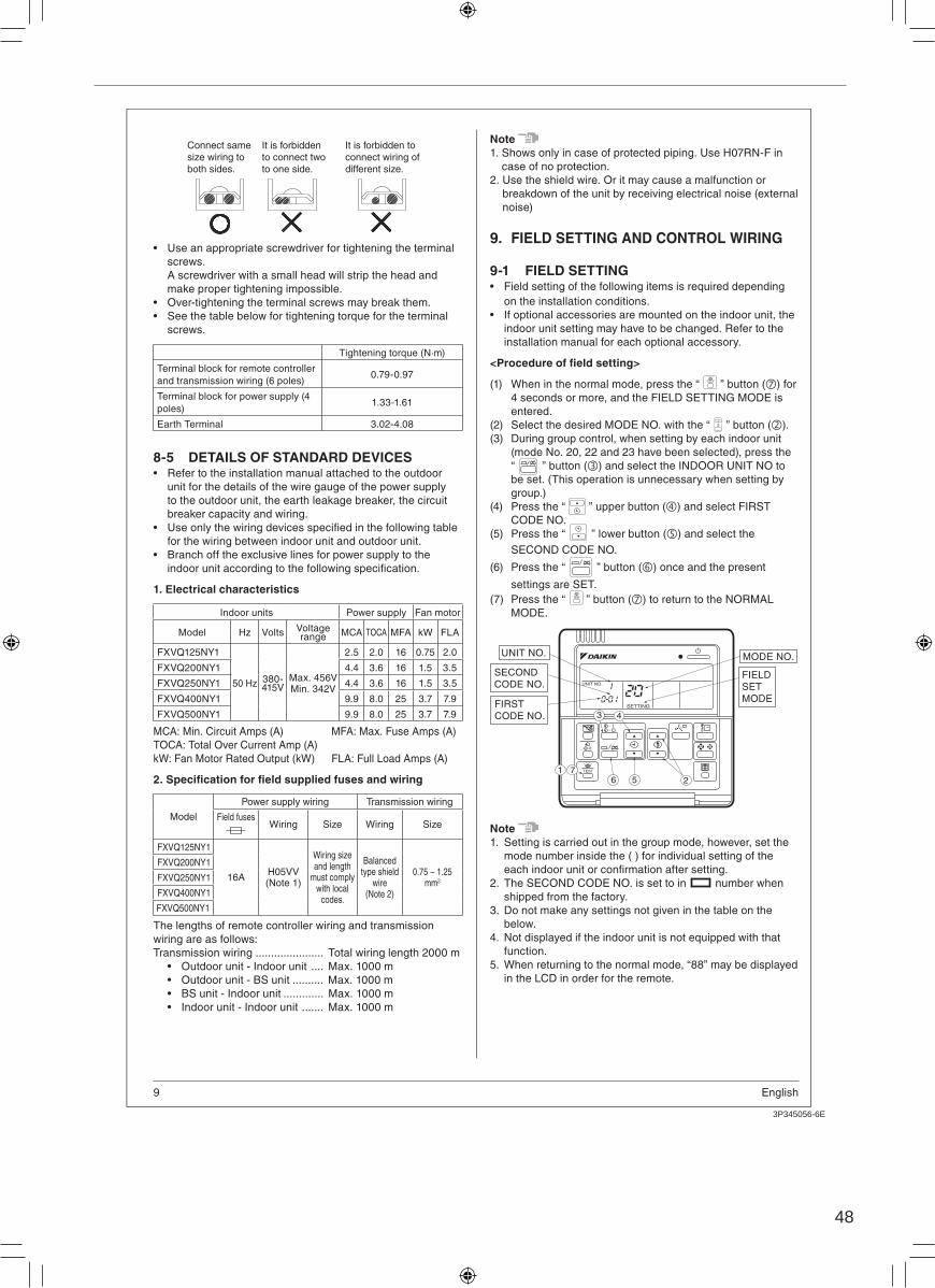
48
3P345056-6E
8English
<400 · 500 type>
Wiring from right side
Earth terminal
Control box
Pass the attached clamp through the resin clamp, and bundle each
Terminal block for the wiring between indoor unit and outdoor unit
Terminal block for power supply wiring
Earth terminal for
shield wire
Wiring from left side
Earth terminal
Control boxPass the attached clamp through the resin clamp, and bundle each
Terminal block for the wiring between indoor unit and outdoor unit
Terminal block for power supply wiring
Earth terminal
for shield wire
8-3 EXAMPLE OF WIRINGThe control panel is the standard built-in.
Ex1. When using in pairs
Prohibited
Indoor unit A
OUT-OUT
Outdoor unit
F1 F2 F1 F2IN-OUTControl box
Contr
ol p
anel
Earth
Power supply
Branch switch Overcurrent circuit breaker
L2 L3 NL1P1orP
P2orN
F1F2 T1T2
The wiring between indoor unit and outdoor unit
Never to connect high-voltage electricity such as power supply cables.
Ex2. For multiple indoor units
Prohibited
Final indoor unitIndoor unit B
Outdoor unit
IN-OUT
Control boxOUT-OUT
Indoor unit A
Earth
Contr
ol panel
Contr
ol panel
Contr
ol panel
Power supply
Power supply
Power supply
Branch switch Overcurrent circuit breaker
Branch switch Overcurrent circuit breaker
Branch switch Overcurrent circuit breaker
F1 F2 F1 F2
The wiring between indoor unit and outdoor unit
The wiring between indoor unit and indoor unit
P1orP
P2orN
F1
F2
T1
T2
P1orP
P2orN
F1
F2
T1
T2
P1orP
P2orN
F1
F2
T1
T2
Earth Earth
Never to connect high-voltage electricity such as power supply cables.
L2 L3 NL1 L2 L3 NL1 L2 L3 NL1
CAUTION
Do not have low-voltage wires (wiring between units) and other
high-voltage run through the same locations, and there must
be min. 50 mm distance between wires outside of the unit.
Or it may cause a malfunction or a breakdown of the unit by
receiving electrical noise (external noise).
Ex3. For group control
Prohibited
Indoor unit A Final indoor unitIndoor unit B
The wiring between indoor unit and outdoor unit
The wiring between indoor unit and indoor unit
Control boxOUT-OUTIN-OUT
Outdoor unit
Earth
Earth
Earth
Contr
ol panel
Power
supply
Branch switch Overcurrent circuit breaker Never to connect
high-voltage electricity
such as power supply cables.
F1 F2 F1 F2
L2 L3 NL1 L2 L3 NL1 L2 L3 NL1P1orP
P2orN
F1
F2
T1
T2
P1orP
P2orN
F1
F2
T1
T2
P1orP
P2orN
F1
F2
T1
T2
Note 1. It is not necessary to set the indoor unit address for group
control. (The setting is made automatically when the power supply is turned on.)
2. Make sure to disconnect the control panel wiring of the units over the second one.
3. In this case, all indoor units within the group are controlled by the control panel for the group control.
Ex4. When including BS unitProhibited
Prohibited
The wiring between
outdoor unit and BS unit
The wiring between
indoor unit and BS unit
Earth
Power
supply Control boxOUT-OUTIN-OUT
Outdoor unit
F1 F2 F1 F2
Branch switch Overcurrent circuit breaker
*Contr
ol p
anel
Indoor unit A
L2 L3 NL1P1orP
P2orN
F1
F2
T1
T2
Control boxIndoorOutdoor
BS unit
F1 F2 F1 F2
Never to
connect
high-voltage
electricity
such as power
supply cables.
Never to connect
high-voltage electricity
such as power supply cables.
8-4 PRECAUTIONS WHEN LAYING POWER WIRING
Note
Use ring type crimp style terminals for connections to the
power terminal block.
Install the insulating sleeve for insulation of crimp part.
When none are available, follow the instructions below.
If stranded wires are used, do not solder the front end of
the wires.
Do not connect wiring of different size to the power
terminal block. (Slack in the power wiring may cause
abnormal heat.)
When transmission wiring which is the same thickness, do
For wiring, use the designated power wire and connect
exerted on the terminal board.
Insulating sleevePower wire
Ring type crimp
style terminal
2
3P345056-6E
9 English
Connect same
size wiring to
both sides.
It is forbidden
to connect two
to one side.
It is forbidden to
connect wiring of
different size.
Use an appropriate screwdriver for tightening the terminal
screws.
A screwdriver with a small head will strip the head and
make proper tightening impossible.
Over-tightening the terminal screws may break them.
See the table below for tightening torque for the terminal
screws.
Tightening torque (N·m)
Terminal block for remote controller
and transmission wiring (6 poles)0.79-0.97
Terminal block for power supply (4
poles)1.33-1.61
Earth Terminal 3.02-4.08
8-5 DETAILS OF STANDARD DEVICESRefer to the installation manual attached to the outdoor
unit for the details of the wire gauge of the power supply
to the outdoor unit, the earth leakage breaker, the circuit
breaker capacity and wiring.
for the wiring between indoor unit and outdoor unit.
Branch off the exclusive lines for power supply to the
1. Electrical characteristics
Indoor units Power supply Fan motor
Model Hz Volts Voltage range MCA TOCA MFA kW FLA
FXVQ125NY1
50 Hz 380-415V
Max. 456VMin. 342V
2.5 2.0 16 0.75 2.0
FXVQ200NY1 4.4 3.6 16 1.5 3.5
FXVQ250NY1 4.4 3.6 16 1.5 3.5
FXVQ400NY1 9.9 8.0 25 3.7 7.9
FXVQ500NY1 9.9 8.0 25 3.7 7.9
MCA: Min. Circuit Amps (A) MFA: Max. Fuse Amps (A)
TOCA: Total Over Current Amp (A)
kW: Fan Motor Rated Output (kW) FLA: Full Load Amps (A)
Model
Power supply wiring Transmission wiring
Field fusesWiring Size Wiring Size
FXVQ125NY1
16AH05VV (Note 1)
Wiring size and length
must comply with local
codes.
Balanced type shield
wire (Note 2)
mm2
FXVQ200NY1
FXVQ250NY1
FXVQ400NY1
FXVQ500NY1
The lengths of remote controller wiring and transmission
wiring are as follows:
Transmission wiring ...................... Total wiring length 2000 m
Outdoor unit - Indoor unit .... Max. 1000 m
Outdoor unit - BS unit .......... Max. 1000 m
BS unit - Indoor unit ............. Max. 1000 m
Indoor unit - Indoor unit ....... Max. 1000 m
Note
1. Shows only in case of protected piping. Use H07RN-F in
case of no protection.
2. Use the shield wire. Or it may cause a malfunction or
breakdown of the unit by receiving electrical noise (external
noise)
9. FIELD SETTING AND CONTROL WIRING
9-1 FIELD SETTINGField setting of the following items is required depending
on the installation conditions.
If optional accessories are mounted on the indoor unit, the
indoor unit setting may have to be changed. Refer to the
installation manual for each optional accessory.
(1) When in the normal mode, press the “ TEST ” button ( ) for
4 seconds or more, and the FIELD SETTING MODE is
entered.
(2) Select the desired MODE NO. with the “ ” button ( ).
(3) During group control, when setting by each indoor unit
(mode No. 20, 22 and 23 have been selected), press the
“ ” button ( ) and select the INDOOR UNIT NO to
be set. (This operation is unnecessary when setting by
group.)
(4) Press the “ ” upper button ( ) and select FIRST
CODE NO.
(5) Press the “ ” lower button ( ) and select the
SECOND CODE NO.
(6) Press the “ ” button ( ) once and the present
settings are SET.
(7) Press the “ TEST ” button ( ) to return to the NORMAL
MODE.
SETTING
TEST
UNIT NO.
3 4
5671
2
UNIT NO. MODE NO.
SECOND
CODE NO.
FIRST
CODE NO.
FIELD
SET
MODE
Note
1. Setting is carried out in the group mode, however, set the
mode number inside the ( ) for individual setting of the
2. The SECOND CODE NO. is set to in number when
shipped from the factory.
3. Do not make any settings not given in the table on the
below.
4. Not displayed if the indoor unit is not equipped with that
function.
5. When returning to the normal mode, “88” may be displayed
in the LCD in order for the remote.
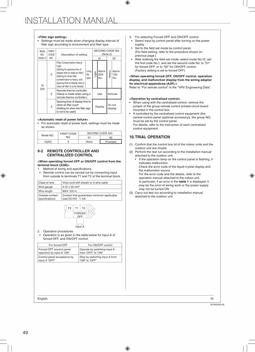
49
3P345056-6E
10English
<Filter sign setting>
Settings must be made when changing display interval of
Mode
NO.
(Note.1)
FIRST
CODE
NO.
Description of setting
SECOND CODE NO.
(Note.2)
01 02
10
(20)
0
Filter Contamination-Heavy/
Light
(Setting for spacing time of
contamination is heavy, and
spacing time of display time to
Long
life
type
Lig
ht Approx.
2500
Hrs. He
avy Approx.
1250
Hrs.
2
Remote thermo-controller
(Setup is made when using a
remote thermo-controller.)
Use Nonuse
3
Spacing time of display time to
is not to be used)
DisplayDo not
display
<Automatic reset of power failure>
For automatic reset of power fault, settings must be made
as shown.
Mode NO.FIRST CODE
NO.
SECOND CODE NO.
01 02
12(22) 5 None Provided
9-2 REMOTE CONTROLLER AND CENTRALIZED CONTROL
<When operating forced OFF or ON/OFF control from the
terminal block (X3M)>
Remote control can be carried out by connecting input
from outside to terminals T1 and T2 of the terminal block.
Class of wire Vinyl cord with sheath or 2-wire cable
Wire gauge 0.75-1.25 mm2
Wire length MAX 100 m
Outside contact Contact that guarantees minimum applicable
load DC15V · 1 mA
Input A
F2 T1 T2
FORCED
OFF
2. Operation procedures
Operation is as given in the table below for input A of
forced OFF, and ON/OFF control.
For forced OFF For ON/OFF control
Forced OFF (control panel
rejection) by input A “ON”
Operate by switching input A
from “OFF” to “ON”
Control panel acceptance by
input A “OFF”
Stop by switching input A from
“ON” to “OFF”
3. For selecting Forced OFF and ON/OFF control
Select input by control panel after turning on the power
supply.
previous page.)
for forced OFF, or to “02” for ON/OFF control.
(Factory setting is set to forced OFF)
<When operating forced OFF, ON/OFF control, operation
display, and malfunction display from the wiring adaptor
for electrical appendices (A2P).>
Refer to “For remote control” in the “VRV Engineering Data”.
<Operation by centralized control>
When using with the centralized control, remove the
jumper of the group remote control printed circuit board
mounted in the control box.
If controlled by the centralized control equipment (the
central control panel (optional accessory)), the group NO.
must be set by the control panel.
For details, refer to the instruction of each centralized
control equipment.
10. TRIAL OPERATION
(1)
outdoor unit are closed.
(2) Perform the test run according to the installation manual
attached to the outdoor unit.
indicates malfunction.
Check the error code of the liquid crystal display and
the malfunction source.
For the error code and the details, refer to the
operation manual attached to the indoor unit.
In particular, if an error in the table 1 is displayed, it
may be the error of wiring work or the power supply
may not be turned ON.
(3) Carry out test run according to installation manual
attached to the outdoor unit.
2
3P345056-6E
11 English
(Table 1)
Control panel
(remote
controller)
display
Content Solution
“Under
centralized
control”
Terminal for forced OFF
(T1·T2) may be short
circuiting.
Fix not to short
circuit.
“U4”
“UH”
The power supply of the
outdoor unit may not turned
ON.
The power supply of the
outdoor unit may not be
installed yet.
Misconnection between the
transmission wiring, and the
control panel wiring or the
forced OFF wiring.
Disconnection of the
transmission wiring.
Turn on the power
of outdoor unit.
Proceed installation
work for power
supply.
Fix the wiring.
NOT
display
The power supply of the
indoor unit is not turned ON.
The power supply of the
indoor unit may not be
installed yet.
Misconnection between the
transmission wiring, and the
control panel wiring or the
forced OFF wiring.
Disconnection of the control
panel wiring.
Turn on the power
of indoor unit.
Proceed installation
work for power
supply.
Fix the wiring.
“E4” A test run is carried out from
outdoor unit in a wrong mode
(other than “standard” mode).
Select the
“standard” mode,
then test run again
from outdoor unit.
“A6”
expected (overcurrent).
Adjust the external
static pressure.
WARNING
is not completed, instruct the user not to operate until the
work is completed for protecting the indoor unit.
indoor unit, which may result in water splash or leak.
INSTALLATION MANUAL
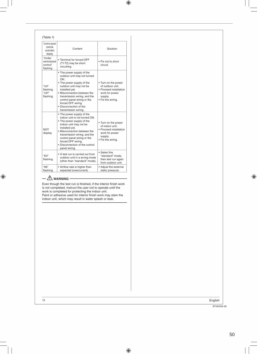
50
3P345056-6E
10English
<Filter sign setting>
Settings must be made when changing display interval of
Mode
NO.
(Note.1)
FIRST
CODE
NO.
Description of setting
SECOND CODE NO.
(Note.2)
01 02
10
(20)
0
Filter Contamination-Heavy/
Light
(Setting for spacing time of
contamination is heavy, and
spacing time of display time to
Long
life
type
Lig
ht Approx.
2500
Hrs. He
avy Approx.
1250
Hrs.
2
Remote thermo-controller
(Setup is made when using a
remote thermo-controller.)
Use Nonuse
3
Spacing time of display time to
is not to be used)
DisplayDo not
display
<Automatic reset of power failure>
For automatic reset of power fault, settings must be made
as shown.
Mode NO.FIRST CODE
NO.
SECOND CODE NO.
01 02
12(22) 5 None Provided
9-2 REMOTE CONTROLLER AND CENTRALIZED CONTROL
<When operating forced OFF or ON/OFF control from the
terminal block (X3M)>
Remote control can be carried out by connecting input
from outside to terminals T1 and T2 of the terminal block.
Class of wire Vinyl cord with sheath or 2-wire cable
Wire gauge 0.75-1.25 mm2
Wire length MAX 100 m
Outside contact Contact that guarantees minimum applicable
load DC15V · 1 mA
Input A
F2 T1 T2
FORCED
OFF
2. Operation procedures
Operation is as given in the table below for input A of
forced OFF, and ON/OFF control.
For forced OFF For ON/OFF control
Forced OFF (control panel
rejection) by input A “ON”
Operate by switching input A
from “OFF” to “ON”
Control panel acceptance by
input A “OFF”
Stop by switching input A from
“ON” to “OFF”
3. For selecting Forced OFF and ON/OFF control
Select input by control panel after turning on the power
supply.
previous page.)
for forced OFF, or to “02” for ON/OFF control.
(Factory setting is set to forced OFF)
<When operating forced OFF, ON/OFF control, operation
display, and malfunction display from the wiring adaptor
for electrical appendices (A2P).>
Refer to “For remote control” in the “VRV Engineering Data”.
<Operation by centralized control>
When using with the centralized control, remove the
jumper of the group remote control printed circuit board
mounted in the control box.
If controlled by the centralized control equipment (the
central control panel (optional accessory)), the group NO.
must be set by the control panel.
For details, refer to the instruction of each centralized
control equipment.
10. TRIAL OPERATION
(1)
outdoor unit are closed.
(2) Perform the test run according to the installation manual
attached to the outdoor unit.
indicates malfunction.
Check the error code of the liquid crystal display and
the malfunction source.
For the error code and the details, refer to the
operation manual attached to the indoor unit.
In particular, if an error in the table 1 is displayed, it
may be the error of wiring work or the power supply
may not be turned ON.
(3) Carry out test run according to installation manual
attached to the outdoor unit.
2
3P345056-6E
11 English
(Table 1)
Control panel
(remote
controller)
display
Content Solution
“Under
centralized
control”
Terminal for forced OFF
(T1·T2) may be short
circuiting.
Fix not to short
circuit.
“U4”
“UH”
The power supply of the
outdoor unit may not turned
ON.
The power supply of the
outdoor unit may not be
installed yet.
Misconnection between the
transmission wiring, and the
control panel wiring or the
forced OFF wiring.
Disconnection of the
transmission wiring.
Turn on the power
of outdoor unit.
Proceed installation
work for power
supply.
Fix the wiring.
NOT
display
The power supply of the
indoor unit is not turned ON.
The power supply of the
indoor unit may not be
installed yet.
Misconnection between the
transmission wiring, and the
control panel wiring or the
forced OFF wiring.
Disconnection of the control
panel wiring.
Turn on the power
of indoor unit.
Proceed installation
work for power
supply.
Fix the wiring.
“E4” A test run is carried out from
outdoor unit in a wrong mode
(other than “standard” mode).
Select the
“standard” mode,
then test run again
from outdoor unit.
“A6”
expected (overcurrent).
Adjust the external
static pressure.
WARNING
is not completed, instruct the user not to operate until the
work is completed for protecting the indoor unit.
indoor unit, which may result in water splash or leak.

Warning
Specifications, designs and other content appearing in this brochure are current as of June 2015 but subject to change without notice.
SERVICE AND SPARE PARTS, Telp.: 021-736 92899 • Training Center, Telp. : 021-295 61950 • Bekasi, Telp.: 021-2945 0585,Tangerang, Telp.: 021-5314 1195 • Bandung, Telp.: 022-5225 150 • Semarang, Telp.: 024-841 2695 • Yogyakarta, Telp.: 0274-551 321 Surabaya, Telp.: 031-503 1138 • Denpasar, Telp.: 0361-900 5514 • Makassar, Telp.: 0411-446 263 • Palembang, Telp.: 0711-319 776
HEAD OFFICE :