air mite catalog
TRANSCRIPT
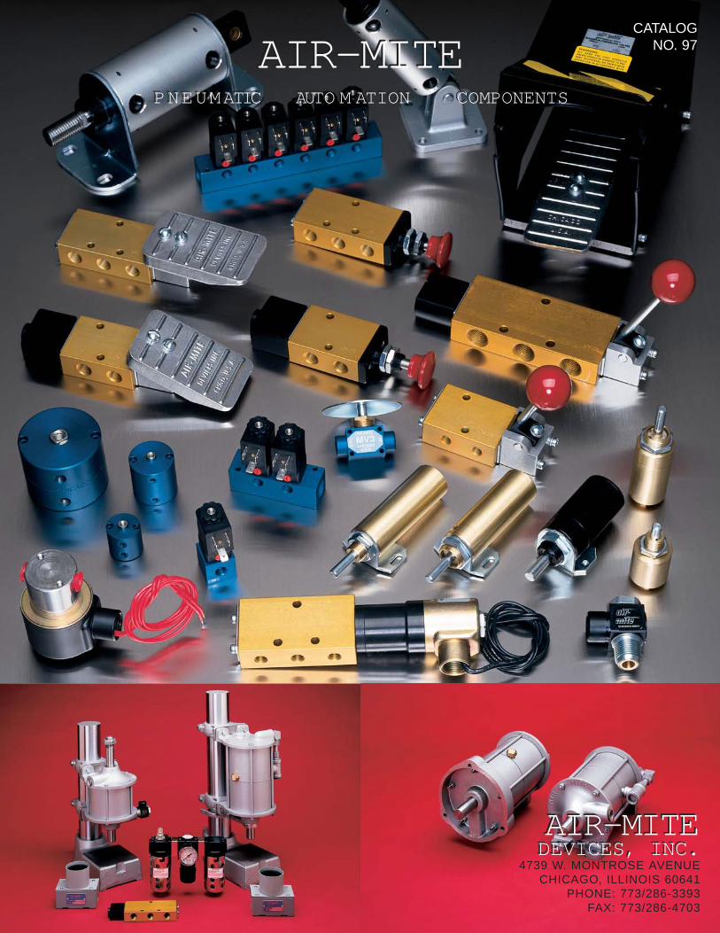
AIR-MITEPNEUMATIC AUTO M ATION COMPONENTS
AIR-MITEPNEUMATIC AUTO M ATION COMPONENTS
AIR-MITEDEVICES, INC.AIR-MITEDEVICES, INC.
4739 W. MONTROSE AVENUECHICAGO, ILLINOIS 60641
PHONE: 773/286-3393FAX: 773/286-4703
CATALOGNO. 97

2
introductionAir Power, the harnessed servant of industrial progress, eliminates time waste anddrudgery. Makes work handling fast, economical and automatic. If you want the mosteconomical, adaptable and speedy impetus to all pressure, needs AIR POWER has norival. Feeding work to machines, holding, exerting aimed and precisional pressure,lifting or handling heavy equipment, AIR POWER is your best solution.
This catalog has been designed to provide you with all the necessary information youneed to select the proper AIR-MITE equipment to meet your specific requirements.Variations or special units other than those shown are available upon request.
index PageMighty Mite Short Stroke Cylinders 3
Air Arbor Presses 4-5
Classic Design CylindersTandem & Triplex 6-7
Foot Mounted Models 8-9Front Flange Mounted Models 10-11Rear Flange Mounted Models 12-13
Pull Models 12-13Clevis Mounted Models 12-13
DAR Cylinders 14-15
Micro Model Cylinders 16-17
V-Series Control ValvesValve Types & Order Information 18-19
V3 Series 3-Way Valves 20-22V4 & V5 Series 4-Way Valves 23-25
V4 & V5 Series - 3 Position Valves 26
Safety Foot Guard 27
V3 & V4 Pilot Valves–Standard 28V3 & V4 Pilot Valves–Low Pressure 29
V3 & V4 Series–Solenoid Valves 30-31
S2 & S3 Series–Solenoid Valves 32-33S5 Series–Miniature Solenoid Valves 34-35
VDB Series 2 & 3-Way Solenoid Valves 36-37Connectors for VDB Series 37
MV2 Series Miniature Valves 38-39
MV3 & MV3P Poppet Valves 40
Slide Valves, Quick Exhaust Valves 40
Flow Control, Needle, Check Valves 41
PC2500 Safety Controls 42-43
SC3000 Safety Controls–Stand Alone 44SC3300 Safety Controls–Press Ready 45
LV3 Series–Safety Lockout Valves 46V101 & V202 Lockout Slide Valves 46
Miniature Air Components 47
Air Volume Chambers 47
Filter-Regulator-Lubricator Units 48-49
Vacuum Pumps 50-51
Roto-Flo Speed Controls 52
Exhaust Silencers & Mufflers 53
Vacuum Electric Switches 53
Air Holding Collet Fixtures 54
Air Line Instant Fittings 55
Power Conversion Table Back Cover
Suggested Rod End Styles–Chart Back Cover
PRICES AND QUOTATION Prices are subject to change without notice, but any such change shall not affectorders already accepted. Quotations are firm for 30 days only.
MINIMUM CHARGE Minimum billing on any order is $25.00 net.
RETURNED GOODS No purchases are to be returned after shipment for any reason unless our writtenacceptance has first been obtained. All returns are subject to a 20% restockingcharge. All shipping charges shall be prepaid. No goods returned after 6 months.
DESIGN Manufacturer reserves the right to alter specifications and/or dimensions withoutnotice. Seller assumes no responsibility for revision of models already in the field.
SPECIAL PRODUCTS Orders for special products are not subject to cancellation. Cylinder orders are con-sidered special, due to stroke, rod extension, thread, etc., and therefore non-can-cellable.
TERMS OF PAYMENT NET–30 Days F.O.B. Chicago, Ill.
Please see page 42 in this catalog for full information on anti tie-down con-trols.
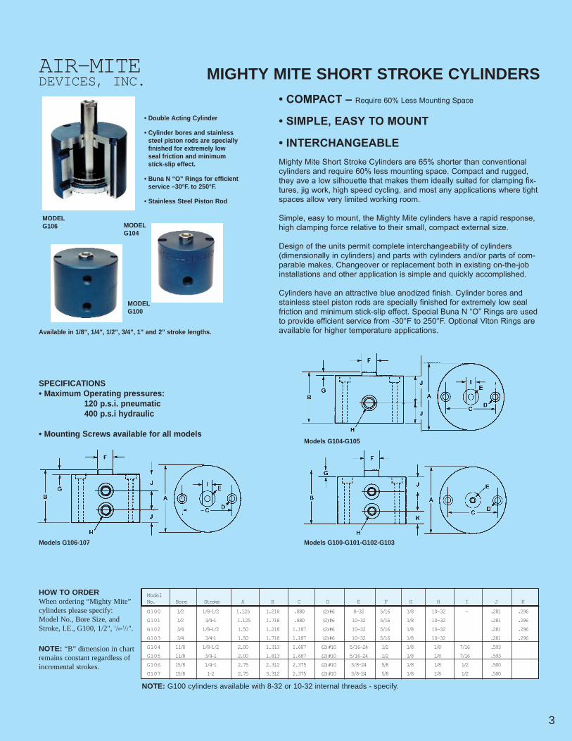
• Double Acting Cylinder
• Cylinder bores and stainlesssteel piston rods are speciallyfinished for extremely lowseal friction and minimumstick-slip effect.
• Buna N “O” Rings for efficientservice –30°F. to 250°F.
• Stainless Steel Piston Rod
MIGHTY MITE SHORT STROKE CYLINDERS
• COMPACT – Require 60% Less Mounting Space
• SIMPLE, EASY TO MOUNT
• INTERCHANGEABLEMighty Mite Short Stroke Cylinders are 65% shorter than conventionalcylinders and require 60% less mounting space. Compact and rugged,they ave a low silhouette that makes them ideally suited for clamping fix-tures, jig work, high speed cycling, and most any applications where tightspaces allow very limited working room.
Simple, easy to mount, the Mighty Mite cylinders have a rapid response,high clamping force relative to their small, compact external size.
Design of the units permit complete interchangeability of cylinders(dimensionally in cylinders) and parts with cylinders and/or parts of com-parable makes. Changeover or replacement both in existing on-the-jobinstallations and other application is simple and quickly accomplished.
Cylinders have an attractive blue anodized finish. Cylinder bores andstainless steel piston rods are specially finished for extremely low sealfriction and minimum stick-slip effect. Special Buna N “O” Rings are usedto provide efficient service from -30°F to 250°F. Optional Viton Rings areavailable for higher temperature applications.
MODELG106 MODEL
G104
MODELG100
Available in 1/8”, 1/4”, 1/2”, 3/4”, 1” and 2” stroke lengths.
SPECIFICATIONS• Maximum Operating pressures:
120 p.s.i. pneumatic400 p.s.i hydraulic
• Mounting Screws available for all models
HOW TO ORDERWhen ordering “Mighty Mite”cylinders please specify:Model No., Bore Size, andStroke, I.E., G100, 1/2", 1/8-1/2".
NOTE: “B” dimension in chartremains constant regardless ofincremental strokes.
3
AIR-MITEDEVICES, INC.
G100 1/2 1/8-1/2 1.125 1.218 .880 (2)#6 8-32 5/16 1/8 10-32 - .281 .296
G101 1/2 3/4-1 1.125 1.718 .880 (2)#6 10-32 5/16 1/8 10-32 .281 .296
G102 3/4 1/8-1/2 1.50 1.218 1.187 (2)#6 10-32 5/16 1/8 10-32 .281 .296
G103 3/4 3/4-1 1.50 1.718 1.187 (2)#6 10-32 5/16 1/8 10-32 .281 .296
G104 11/8 1/8-1/2 2.00 1.313 1.687 (2)#10 5/16-24 1/2 1/8 1/8 7/16 .593
G105 11/8 3/4-1 2.00 1.813 1.687 (2)#10 5/16-24 1/2 1/8 1/8 7/16 .593
G106 15/8 1/4-1 2.75 2.312 2.375 (2)#10 3/8-24 5/8 1/8 1/8 1/2 .500
G107 15/8 1-2 2.75 3.312 2.375 (2)#10 3/8-24 5/8 1/8 1/8 1/2 .500
ModelNo. Bore Stroke A B C D E F G H I J K
Models G104-G105
Models G100-G101-G102-G103Models G106-107
NOTE: G100 cylinders available with 8-32 or 10-32 internal threads - specify.

4 Please see page 42 in this catalog for full information on anti tie-down con-trols.
AIR ARBOR PRESSESCAPACITIES 1/4, 1/2, 3/4, 1, 2, 3 TON
PRESS SELECTION
Air-Mite has been manufacturing air arbor press-es since 1952. Today, our complete and expand-ed line of production presses offers as muchaccuracy and precision as your tooling requires—all at an affordable price.
Cylinders have a durable, maintenance-free con-struction that assures uninterrupted service. Solidsteel column provides greater strength and rigidi-ty. Unlimited ram clearance is available by speci-fying “daylight” or work area distance required.Ram guides to prevent ram rotation are standardon the DAP38 and DAP58 models, and are offeredas optional equipment for all other presses.
Air arbor presses are available as either springreturn–with “AP” designation–or as double actingwith “DAP” designation–models. All presses canbe supplied with double rod end cylinders–with“DR” designation. Double rod end presses areespecially useful for: (1) applications requiring a
greater bearing surface for vertical axis stabilityand (2) for “micro” adjustment of the piston rodtravel on the down stroke. For these reasons,AIR-MITE strongly recommends the (DR) pressesfor most applications.
PRESS SELECTION–Presses are rated accord-ing to the deliverable force provided by the differ-ent models at varying psi of “in” line pressure. Air-Mite Model Nos. are the key to the deliverableforce. Tandem presses–Models DAP14, 24, and38–deliver double the force of other presses forthe same bore and at the same “in” line pressure.Triplex presses–Model DAP58DR–deliver triplethe force of other presses for the same bore andat the same “in” line pressure. Eg., the following5” bore presses deliver different pounds of forceat 100 psi “in” line pressure: DAP19 models deliv-er 1900 pounds; DAP38 models deliver 3800pounds; DAP58DR models deliver 5800 pounds.
Applications• Basic crimping, forming, pressing, stamping,
broaching• Complicated die sets, electronics, medical
products
Basic Daylight (Work Area) Distance – AllModelsStandard 6" clearance – from retracted rod to
base platenAdditional daylight area – specify additional
when ordering
Stroke & Stroke Adjustment• Standard–as shown, Additional–as requiredDR (Double Rod) Models–top rod threaded UNF
with mtg nuts providedLower rod threaded–additional charge
Rod End Options• Type 1–Blank (Plain) rod end• Type 2–Full Thread – Male UNF or UNC• Type 3–Reduced diameter male UNF or UNC
thread• Type 4–Female UNF thread• Type 5–Per customer requirement* See chart on back cover
Standard Rod ExtensionModel 150 - 1"Models 225, 300, 400, 500 - 1.5"Models 550, 580 - 2"Longer extensions available
Ram Guides–standard on DAP38, DAP38DR &DAP58DR models–for applications requiringnon-rotating rod during press cycling.• Type A – Yoke design attaching rod to OD of
press column – standard guide• Type B – Keywayed into steel or chromed
column
Operating PressuresMinimum Pressures—25-30 psi,
Maximum Pressure—120 psi
Safety ControlsControls specifically designed for all
presses–two hand non-tie down controlsStand alone–self-contained or modular designsPress Ready–specifically designed for presses -
a complete package ready to install - see p. 45
WARNING:Whenever air arbor presses are manuallyoperated two hand anti-tie down controls mustbe used. Presses are sold under conditionsthat all OSHA regulations be met by users.
DOUBLEBRACKETCYLINDERMOUNTING
2,3 TONMODELS
DOUBLEBRACKETCYLINDERMOUNTING
3/4, 11/4, and 2 TONMODELS
SHORTERSTROKECYLINDERMOUNTING
1/4, 1/2, 3/4, 1 TONMODELS
LONGERSTROKECYLINDERMOUNTING
1/4, 1/2, 3/4, 1 TONMODELS
SHORTERSTROKECYLINDERMOUNTING
1/4, 1/2, 3/4, 1 TONMODELS
LONGERSTROKECYLINDERMOUNTING
1/4, 1/2, 3/4, 1 TONMODELS
AIR-MITEDEVICES, INC.

PipeR SizeW eight
6 1/2 NPT 100
Bore PowerModel Size Capacity Factor A B C D E F G H I J K L M N O P
DAP38DR 5 2 Ton 38-1 5 7/8 11 7/8 2 9/16 5 1/16 5 1/16 2 4 9/16 3 1 7 5/8 10 5/8 17 1/4 19 21 1/2 1/2 5 1/2
DAP58DR 5 3 Ton 58-1 5 7/8 11 7/8 2 9/16 5 1/16 5 1/16 2 4 9/16 3 1 12 9/16 14 3/4 22 1/4 23 26 1/2 1/2 6 1/4
DOUBLE ACTING-AIR
*Cylinder stroke optional. *Column length optional. Ram guides optional. K Dimension figures are approximate
Mounting hole dimensions are available for all presses upon request.
*Column length optional. Ram guides optional. K Dimension figures are approximate
*Longer stroke available on request.*Larger column available on request.
Model Bore Power Pipe NetNo. Size Stroke Factor A B C D E F G H J K L M N Size W eight
AP4 2 1/4 1 1/2 3.98 1 7/8 4 4 1/2 2 1/8 6 1 1/2 2 3/8 4 1 3/4 10 1/8 4 11/16 12 3/4 1/4 NPT 40
AP7 3 1 1/2 7.07 1 3/4 4 3/8 4 1/2 2 1/8 6 1 1/2 2 3/8 4 1 3/4 10 1/8 4 11/16 12 3/4 1/4 NPT 41
AP12 4 2 12.56 2 4 1/8 5 3/4 2 9/16 6 2 3 5 1 7/16 11 7/8 5 7/8 14 1/2 3/8 NPT 71
AP19 5 2 19.63 2 4 11/16 5 1 2 9/16 6 2 3 5 1 7/16 11 7/8 5 7/8 14 1/2 1/2 NPT 73
SINGLE ACTING-SPRING
DAP4 2 1/4 1 3.98 1 7/8 4 4 1/2 2 1/8 6 1 2 3/8 4 1 3/4 10 1/8 4 11/16 12 3/4 1/4 NPT 40
DAP7 3 1 7.07 1 1/2 4 3/8 4 1/2 2 1/8 6 1 2 3/8 4 1 3/4 10 1/8 4 11/16 12 3/4 1/4 NPT 41
DAP12 4 1 1/2 12.56 2 1/2 4 1/8 5 3/4 2 9/16 6 1 1/2 3 5 1 7/16 11 7/8 5 7/8 14 1/2 3/8 NPT 71
DAP19 5 1 1/2 19.63 2 4 9/16 5 1 2 9/16 6 1 1/2 3 5 1 7/16 11 7/8 5 7/8 14 1/2 1/2 NPT 73
DOUBLE ACTING-AIR
Model Bore Power PipeNo. Size Stroke Factor A B C D E F G* H J K L M N* Size W eight
AP4 2 1/4 2 3.98 1 7/8 3 3/4 4 1/2 2 1/8 6 2 2 3/8 4 1 3/4 10 1/8 4 11/16 15 3/4 1/4 NPT 41
AP7 3 2 7.07 1 3/4 4 1/8 4 1/2 2 1/8 6 2 2 3/8 4 1 3/4 10 1/8 4 11/16 15 3/4 1/4 NPT 43
AP12 4 3 12.56 2 5/8 4 5 3/4 2 9/16 6 3 3 5 1 7/16 11 7/8 5 7/8 18 1/2 3/8 NPT 74
AP19 5 3 19.63 2 4 1/2 5 1 2 9/16 6 3 3 5 1 7/16 11 7/8 5 7/8 18 1/2 1/2 NPT 76
SINGLE ACTING-SPRING
DAP4 2 1/4 1 1/2 3.98 1 7/8 3 3/4 4 1/2 2 1/8 6 1 1/2 2 3/8 4 1 3/4 10 1/8 4 11/16 15 1/4 1/4 NPT 40
DAP7 3 1 1/2 7.07 1 1/2 4 1/8 4 1/2 2 1/8 6 1 1/2 2 3/8 4 1 3/4 10 1/8 4 11/16 15 1/4 1/4 NPT 41
DAP12 4 2 12.56 2 1/2 4 5 3/4 2 9/16 6 2 3 5 1 7/16 11 7/8 5 7/8 17 1/2 3/8 NPT 71
DAP19 5 2 19.63 1 7/8 4 1/2 5 1 2 9/16 6 2 3 5 1 7/16 11 7/8 5 7/8 17 1/2 1/2 NPT 72
DOUBLE ACTING-AIR
*Column length optional. *Stroke length optional. Ram guides optional. K Dimension figures
Model Bore Power Pipe NetNo. Size Stroke Factor A B C D* E F G H J K L M N* Size W eight
AP4DR 2 1/4 1 1/2 3.98 1 5/8 4 4 1/2 2 1/8 6 1 1/2 2 3/8 4 1 3/4 10 1/8 4 11/16 12 3/4 1/4 NPT 40
AP7DR 3 1 1/2 7.07 1 1/2 4 3/8 4 1/2 2 1/8 6 1 1/2 2 3/8 4 1 3/4 10 1/8 4 11/16 12 3/4 1/4 NPT 41
AP12DR 4 2 12.56 2 1/2 4 1/8 5 3/4 2 9/16 6 2 3 5 1 7/16 11 7/16 5 7/8 14 1/2 3/8 NPT 73
AP19DR 5 2 19.63 1 7/8 4 11/16 5 1 2 9/16 6 2 3 5 1 7/16 11 7/16 5 7/8 14 1/2 1/2 NPT 75
SINGLE ACTING-SPRING
DAP4DR 2 1/4 1 3.98 1 3/8 4 4 1/2 2 1/8 6 1 2 3/8 4 1 3/4 10 1/8 4 11/16 12 3/4 1/4 NPT 40
DAP7DR 3 1 7.07 1 1/2 4 3/8 4 1/2 2 1/8 6 1 2 3/8 4 1 3/4 10 1/8 4 11/16 12 3/4 1/4 NPT 41
DAP12DR 4 1 1/2 12.56 2 1/2 4 1/8 5 3/4 2 9/16 6 1 1/2 3 5 1 7/16 11 7/8 5 7/8 14 1/2 3/8 NPT 73
DAP19DR 5 1 1/2 19.63 1 7/8 4 11/16 5 1 2 9/16 6 1 1/2 3 5 1 7/16 11 7/8 5 7/8 14 1/2 1/2 NPT 75
DOUBLE ACTING-AIR
*Column length optional. Ram guides optional. K Dimension figures are approximate
PipeR Size W eight
6 1/4 52
6 3/8 90
6 1/2 97
Bore PowerModel Size Capacity Factor A B C D E F G H I J K L M N O P
DAP14 3 3/4Ton 14-1 4 11/16 10 1/8 2 1/8 4 4 2 4 1/8 2 3/8 1/2 6 5/16 9 1/8 12 1/8 16 3/8 19 1/2 1/4 4
DAP24 4 1 1/4 Ton 24-1 5 7/8 11 7/8 2 9/16 5 1/16 5 1/16 2 4 3 3/4 7 3/4 10 15/16 13 1/8 17 3/4 21 1/2 3/8 5 1/2
DAP38 5 2 Ton 38-1 5 7/8 11 7/8 2 9/16 5 1/16 5 1/16 2 4 9/16 3 1 7 9/16 10 3/4 13 19 21 1/2 1/2 6 1/4
DOUBLE ACTING-AIR
Model Bore Power Pipe NetNo. Size Stroke Factor A B C D E F* G* H J K L M N* Size W eight
AP4DR 2 1/4 2 3.98 1 7/8 3 3/4 4 1/2 2 1/8 6 2 2 3/8 4 1 3/4 10 1/8 4 11/16 15 3/4 1/4 NPT 40
AP7DR 3 2 7.07 1 3/4 4 1/8 4 1/2 2 1/8 6 2 2 3/8 4 1 3/4 10 1/8 4 11/16 15 3/4 1/4 NPT 41
AP12DR 4 3 12.56 2 5/8 4 5 3/4 2 9/16 6 3 3 5 1 7/16 11 7/8 5 7/8 18 1/2 3/8 NPT 72
AP19DR 5 3 19.63 2 4 1/2 5 1 2 9/16 6 3 3 5 1 7/16 11 7/8 5 7/8 18 1/2 1/2 NPT 75
SINGLE ACTING-SPRING
DAP4DR 2 1/4 1 1/2 3.98 1 7/8 3 3/4 4 1/2 2 1/8 6 1 1/2 2 3/8 4 1 3/4 10 1/8 4 11/16 15 1/4 1/4 NPT 41
DAP7DR 3 1 1/2 7.07 1 1/2 4 1/8 4 1/2 2 1/8 6 1 1/2 2 3/8 4 1 3/4 10 1/8 4 11/16 15 1/4 1/4 NPT 42
DAP12DR 4 2 12.56 2 1/2 4 5 3/4 2 9/16 6 2 3 5 1 7/16 11 7/8 5 7/8 17 1/2 3/8 NPT 73
DAP19DR 5 2 19.63 2 4 9/16 5 1 2 9/16 6 2 3 5 1 7/16 11 7/8 5 7/8 17 1/2 1/2 NPT 76
DOUBLE ACTING-AIR
5

6 Please see page 42 in this catalog for full information on anti tie-down con-trols.
AIR-MITEDEVICES, INC.
DAP550DR
DAV550
DAVF550
DAVF 550
DAVF550DR
DAP580DR
FOOT MOUNTSINGLE OR DOUBLE ROD ENDDAP550
REAR FLANGE MOUNT
DAV550
FRONT FLANGE MOUNTSINGLE OR DOUBLE
ROD END
DAP550DR
Note: 550 ModelsShown
DAP550
CLASSIC DESIGN TANDEM & TRIPLEX CYLINDERS SINGLE OR DOUBLE ROD END
DAVF550DRDAVF580DR

7Please see page 42 in this catalog for full information on anti tie-down con-trols.
AIR-MITE Tandem & Triplex Cylinders consist oftwo or three separate bore areas mounted in-linewith pistons connected on a common piston rod orrods. They are available in either single or doubleend models. The main advantage of these cylindersis the multiplication of force they can deliver withoutneeding larger bores or higher operating pressure.
All tandem and triplex foot mounted cylinders pro-vide the cylinder component used on all AIR-MITEpresses. All tandem and triplex cylinders shownat left can provide deliverable force in either theextend or retract position. Advise factory whenordering. Unless specified when ordering, cylin-ders will provide force in the extend position.Note: Consult factory for strokes of less than 2" and longer than 6".
The DAV Series-Rear FlangeMount—of tandem and triplexcylinders is for applications requir-ing double or triple the force ofconventional cylinders and stillmaintaining the same flange size.Standard models generate forcein the extend position. Specifywhen ordering if force is requiredin the retract position. For strokesless than 2" or longer than 6"please consult factory.
The DAVF Series-Front Flange Mount—of tandem and triplex cylinders is forapplications requiring double or triple theforce of conventional cylinders. Availablein both single or double rod (DR) endmodels. Standard models generate forcein the extend position. Specify whenordering if force is required in the retractposition. For strokes less than 2" orlonger than 6" please consult factory.
Note: All tandem and triplex cylinders are assembled with side piping or mani-folding. If no piping is required, advise factory when ordering. See pricelist for correct pricing.
PLEASE NOTE: Air cylinders and air presses are required to be used with guards or antitie-down controls as per OSHA regulations. This applies to all cylinders shown on pages6, 7, 8, 9, 10, 11, 12, 13.
Cylinder Rod End Options - See chart on back cover.
Model Power*No. Bore Stroke Factor A B C D E F G H I J K L M N O
DAP350 3 2 14.1 11 1/4 9 3/4 9 1/4 8 7/16 6 15/16 4 1/16 2 1/16 7/16 1/4 1/2 1/4 2 1/2 5 3 1/8 2 3/8
DAP450 4 2 24.1 12 3/4 11 1/4 10 11/16 9 13/16 7 11/16 5 7/16 2 3/4 1/2 27/64 3/4 3/8 3 5/16 6 7/16 4 7/8 3 3/8
DAP550 5 2 38.1 13 11 10 5/8 9 11/16 7 5/8 6 1/2 3 5/16 9/16 27/64 1 1/2 4 7 11/16 5 3 3/8
Model Power*No. Bore Stroke Factor A B C D E F G H I J K L M N O
DAP350DR 3 2 14.1 15 1/4 10 1/4 9 5/16 8 1/2 7 4 1/16 2 1/16 7/16 1/4 1/2 1/4 2 1/2 5 3 1/8 2 3/8
DAP450DR 4 2 24.1 17 1/8 12 10 11/16 9 13/16 7 11/16 5 7/16 2 3/4 1/2 27/64 3/4 3/8 3 5/16 6 7/16 4 7/8 3 3/8
DAP550DR 5 2 38.1 17 1/4 11 3/8 10 5/8 9 11/16 7 5/8 6 1/2 3 5/16 9/16 27/64 1 1/2 4 7 11/16 5 3 3/8
DAP580DR 5 2 58.1 22 16 1/8 15 7/8 14 1/2 12 3/8 6 1/2 3 5/16 9/16 27/64 1 1/2 4 7 11/16 5 3 3/8
Model Power*No. Bore Stroke Factor A B C D E F G H I J
D AV350 3 2 14.1 10 11/16 9 3/16 7 13/16 5/8 1/4 1/2 5/16 2 9/32 2 5/8 6 7/8
D AV450 4 2 24.1 12 1/8 10 1/2 8 5/8 1 3/8 3/4 3/8 3 1/2 3 1/16 7 1/4
D AV550 5 2 38.1 12 5/8 10 1/16 9 1/16 1 1/8 1/2 1 3/8 4 3 1/2 7 9/16
D AV580 5 2 58.1 17 9/16 15 1/16 14 1/16 1 1/8 1/2 1 13/32 4 3 1/2 12 11/16
*Figures are theoretical. See chart on back cover.
*Figures are theoretical. See chart on back cover.
Model Power*No. Bore Stroke Factor A B C D E F G H I
D AVF350 3 2 14.1 10 7/16 8 7/8 1 1/2 1/4 5/16 2 7/8 2 7/16 7
D AVF450 4 2 24.1 12 9 7/8 1 1/8 3/4 3/8 3/8 3 1/2 3 7 9/16
D AVF550 5 2 38.1 13 1/8 10 7/8 1 3/8 1 1/2 3/8 4 3 1/2 7 11/16
D AVF580 5 2 58.1 17 7/8 15 1/4 1 3/8 1 1/2 13/32 4 3 1/2 12 7/16
*Figures are theoretical. See chart on back cover.
Model Power*No. Bore Stroke Factor A B C D E F G H I
D AVF350DR 3 2 14.1 14 5/8 11 1/8 1 1/2 1/4 5/16 2 7/8 2 7/16 7
D AVF450DR 4 2 24.1 16 1/4 10 3/4 1 1/8 3/4 3/8 3/8 3 1/2 3 7 9/16
D AVF550DR 5 2 38.1 17 1/4 10 3/8 1 3/8 1 1/2 3/8 4 3 1/2 7 5/8
D AVF580DR 5 2 58.1 22 15 5/8 1 3/8 1 1/2 3/8 4 3 1/2 12 7/8
*Figures are theoretical. See chart on back cover.
Shown are standard strokes - Additional length as required
Shown are standard strokes - Additional length as required
Shown are standard strokes - Additional length as required
8
AIR-MITEDEVICES, INC.
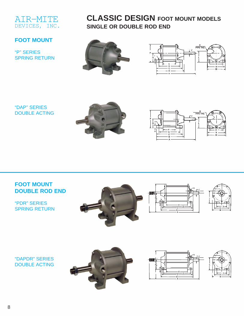
CLASSIC DESIGN FOOT MOUNT MODELSSINGLE OR DOUBLE ROD END
FOOT MOUNT
“P” SERIESSPRING RETURN
FOOT MOUNTDOUBLE ROD END
“PDR” SERIESSPRING RETURN
“DAPDR” SERIESDOUBLE ACTING
“DAP” SERIESDOUBLE ACTING

9Please see page 42 in this catalog for full information on anti tie-down con-trols.
• Cast Impregnated Aluminum End Caps• Oilite Bearings• Extra Long Life Lip Seals – Buna N for smooth
breakaway• Hard Coated Aluminum Tube – Pre-lubed surface for
extended cycle life• Piston Rods – Ground & polished steel• Tie Rod Construction – 5 Tie Rods for maximum
rigidity & stretch on longer stroke models• Operating Pressures: 25-120 psi air• Cylinder Stroke Lengths – Spring return – up to 4"
Double Acting – as required
SPECIFICATIONS – CLASSIC DESIGN SERIES CYLINDERS
ROD END – OPTIONSType 1 Blank-standardType 2 Full thread-male (UNF)Type 3 Reduced diameter male thread (UNF)Type 4 Female UNF threadType 5 Per customer requirementWF Wrench Flats available for all cylinders*See chart on back cover
Rod Clevis - For all classic cylinders
Stock Power*No. Bore Stroke Factor A B C D E F G H I J K L M N O
P150 1 1/2 1 1/2 1.76 5 5/16 4 3/16 4 3 3/8 2 3/16 2 5/16 1 3/16 5/16 3/16 3/8 1/8 1 1/2 2 5/16 2 1/4 1 5/8
P225 2 1/4 1 1/2 3.98 6 3/8 4 13/16 4 9/16 3 3/4 2 3/16 3 3/8 1 11/16 7/16 1/4 1/2 1/4 2 3/16 3 3/8 3 3/16 2 3/8
P300 3 1 1/2 7.07 6 3/8 5 4 5/8 3 3/4 2 5/16 4 3/16 2 1/16 1/2 1/4 1/2 1/4 2 17/32 4 1/8 3 1/8 2 3/8
P400 4 2 12.56 8 1/8 6 5/8 6 5 1/8 3 5 1/2 2 11/16 1/2 3/8 3/4 3/8 3 5/16 5 3/8 4 7/8 3 3/8
P500 5 2 19.63 8 6 3/8 6 5 1/8 3 6 1/2 3 5/16 1/2 3/8 1 1/2 4 6 3/8 5 3 3/8
*Figures are theoretical. See chart on back cover.
Stock Power*No. Bore Factor A B C D E F G H I J K L M N O
DAP150 1 1/2 1.76 5 1/4 4 1/16 3 13/16 3 1/4 2 2 5/16 1 3/16 5/16 3/16 3/8 1/8 1 7/16 2 5/16 2 1/4 1 5/8
DAP225 2 1/4 3.98 6 3/8 4 3/4 4 3/8 3 3/4 2 3/32 3 3/8 1 3/4 7/16 1/4 1/2 1/4 2 3/16 3 1/4 3 3/16 2 3/8
DAP300 3 7.07 6 7/16 4 15/16 4 9/16 3 7/8 2 1/4 4 3/16 2 1/16 1/2 1/4 1/2 1/4 2 17/32 4 3/16 3 3/16 2 3/8
DAP400 4 12.56 7 3/4 6 1/8 5 1/2 4 5/8 2 1/2 5 1/2 2 11/16 1/2 3/8 3/4 3/8 3 1/4 5 1/2 5 3 3/8
DAP500 5 19.63 7 3/4 6 5 9/16 4 5/8 2 1/2 6 1/2 3 5/16 1/2 3/8 1 1/2 3 31/32 6 3/8 5 3 3/8
*Figures are theoretical. See chart on back cover.
Dimensions given are for 1 Stroke
Shown are standard strokes for immediate shipment - Additional as required
The P and DAP double rod end series provide two fea-tures not found on our single rod end models. First, theability to micro adjust the stroke length. Second, agreater bearing surface to minimize deflection of thepiston rod on the workpiece. These models are thecylinder component of our air presses as well as sold
separately as foot mounted cylinders. They offer longlife and high cycling at affordable prices.
Double rod end models are especially useful for appli-cations with exceptionally long strokes where deflectionis a problem.
Stock Power*No. Bore Stroke Factor A B C D E F G H I J K L M N O
P150DR 1 1/2 1 1/2 1.76 8 3/16 4 9/16 4 1/8 3 1/2 2 1/4 2 5/16 1 3/16 5/16 3/16 3/8 1/8 1 7/16 2 5/16 2 1/4 1 5/8
P225DR 2 1/4 1 1/2 3.98 9 13/16 5 5/16 4 5/8 3 3/4 2 3/16 3 3/8 1 11/16 7/16 1/4 1/2 1/4 2 1/4 3 3/8 3 3/16 2 3/8
P300DR 3 1 1/2 7.07 10 5 1/2 4 9/16 3 3/4 2 1/4 4 3/16 2 1/16 5/16 1/4 1/2 1/4 2 1/2 4 1/8 3 1/8 2 3/8
P400DR 4 2 12.56 12 3/8 7 1/4 6 1/16 5 1/8 3 5 1/2 2 11/16 1/2 3/8 3/4 3/8 3 1/4 5 3/8 4 7/8 3 3/8
P500DR 5 2 19.63 12 6 13/16 6 1/16 5 1/8 3 1/16 6 1/2 3 5/16 1/2 3/8 1 1/2 4 6 3/8 5 3 3/8
*Figures are theoretical. See chart on back cover.
Shown are standard strokes - Additional strokes as required
Dimensions given are for 1 Stroke - Additional strokes as required
Stock Power*No. Bore Stroke Factor A B C D E F G H I J K L M N O
DAP150DR 1 1/2 1 1.76 8 1/2 4 1/2 4 3 3/8 2 1/8 2 5/16 1 3/16 5/16 3/16 3/8 1/8 1 7/16 2 5/16 2 1/4 1 5/8
DAP225DR 2 1/4 1 3.98 9 7/16 6 5/16 4 11/16 3 3/4 2 3/16 3 3/8 1 3/4 7/16 1/4 1/2 1/4 2 1/8 3 3/8 3 3/16 2 3/8
DAP300DR 3 1 7.07 9 1/2 6 1/2 4 9/16 3 3/4 2 3/16 4 3/16 2 1/16 1/2 3/8 1/2 1/4 2 1/2 4 3/16 3 3/16 2 3/8
DAP400DR 4 1 12.56 10 7/8 6 3/4 5 9/16 4 5/8 2 1/2 5 1/2 2 11/16 1/2 3/8 3/4 3/8 3 1/4 5 1/2 5 3 3/8
DAP500DR 5 1 19.63 10 5/8 6 5/8 5 9/16 4 5/8 2 9/16 6 1/2 3 5/16 1/2 3/8 1 1/2 4 6 3/8 5 3 3/8
*Figures are theoretical. See chart on back cover.
Cyl Model Clevis150 145A 3/8-24 UNF225, 300 245 A 1/2-20 UNF400 345A 3/4-16 UNF500 445 1"-14 UNF
10 For rod end selection, see page 9.
AIR-MITEDEVICES, INC.
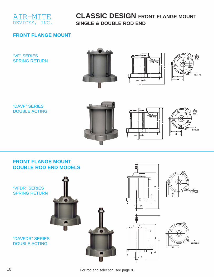
CLASSIC DESIGN FRONT FLANGE MOUNTSINGLE & DOUBLE ROD END
FRONT FLANGE MOUNT
“VF” SERIESSPRING RETURN
“DAVF” SERIESDOUBLE ACTING
FRONT FLANGE MOUNTDOUBLE ROD END MODELS
“VFDR” SERIESSPRING RETURN
“DAVFDR” SERIESDOUBLE ACTING

11Please see page 42 in this catalog for full information on anti tie-down con-trols.
VF & DAVF Front Flange Modelsprovide a piston rod that extendsthrough the mounting surface per-mitting the cylinder to be mountedbehind or under the surface and freeof the work area.
The VF and DAVF Classic SeriesDR cylinders provide a double rodbearing surface for increased stabil-ity and less deflection. A rod nut issupplied on one rod to aid in vari-able stroke adjustment. This affordsthe user a multi stroke capabilitywith just one cylinder.
PLEASE NOTE: Air cylinders and air presses are required to be used with guards or antitie-down controls as per OSHA regulations. This applies to all cylinders shown on pages6, 7, 8, 9, 10, 11, 12, 13.
Longer strokes available consult factory
Longer strokes available consult factoryDimensions given for 1 stroke
Model Power*No. Bore Stroke Factor A B C D E F G H I
VF150DR 1 1/2 1 1/2 1.76 8 1/4 4 11/16 3/8 3/8 1/8 3/16 1 11/16 1 7/16 3 1/16
VF225DR 2 1/4 1 1/2 3.98 9 13/16 5 7/16 1/2 1/2 1/4 1/4 2 1/4 2 3 3/8
VF300DR 3 1 1/2 7.07 10 3/16 5 11/16 5/8 1/2 1/4 5/16 2 7/8 2 7/16 3 7/16
VF400DR 4 2 12.56 12 3/8 7 3/8 1 1/8 3/4 3/8 3/8 3 1/2 3 4 3/16
VF500DR 5 2 19.63 11 3/8 6 3/8 1 3/8 1 1/2 3/8 4 3 1/2 3 5/8
*Figures are theoretical. See chart on back cover.
Model Power*No. Bore Stroke Factor A B C D E F G H I
D AVF150DR 1 1/2 1 1.76 8 1/8 4 1/8 3/4 3/8 1/8 3/16 1 3/4 1 7/16 2 3/16
D AVF225DR 2 1/4 1 3.98 2 13/16 4 9/16 7/8 1/2 1/4 5/16 2 3/8 2 2 1/8
D AVF300DR 3 1 7.07 9 1/16 4 15/16 1 1/2 1/4 5/16 2 7/8 2 7/16 2 1/4
D AVF400DR 4 1 12.56 10 1/8 5 13/16 1 1/8 3/4 3/8 3/8 3 1/2 3 2 9/16
D AVF500DR 5 1 19.63 12 9/16 5 3/4 1 3/8 1 1/2 3/8 4 3 1/2 3 1/16
*Figures are theoretical. See chart on back cover.
Model Power*No. Bore Stroke Factor A B C D E F G H
VF150 1 1/2 1 1/2 1.76 5 1/4 4 1/4 1/2 3/8 1/8 3/16 1 11/16 1 7/16
VF225 2 1/4 1 1/2 3.98 6 1/8 4 3/4 1/2 1/2 1/4 1/4 2 1/4 2
VF300 3 1 1/2 7.07 6 3/8 5 1/8 5/8 1/2 1/4 5/16 2 3/4 2 7/16
VF400 4 2 12.56 8 1/4 6 1/2 1 1/16 3/4 3/8 3/8 3 1/2 3
VF500 5 2 19.63 7 3/4 6 1/4 1 1/8 1 1/2 3/8 4 3 1/2
*Figures are theoretical. See chart on back cover.
Model Power*No. Bore Factor A B C D E F G H I
D AV F150 1 1/2 1.76 5 1/8 4 1/16 7/8 3/8 1/8 3/16 1 3/4 1 7/16
D AV F225 2 1/4 3.98 6 1/16 4 1/8 7/8 1/2 1/4 1/4 2 3/8 2
D AV F300 3 7.07 5 11/16 4 3/16 1 1/2 1/4 5/16 2 7/8 2 7/16 2 9/32
D AV F400 4 12.56 7 4 15/16 11/16 3/4 3/8 3/8 3 1/2 3 2 9/16
D AV F500 5 19.63 7 1/8 5 1/8 11/8 1 1/2 3/8 4 3 1/2 2 9/16
*Figures are theoretical. See chart on back cover.
Given dimensions include 1 of stroke advise length of stroke required.
Cylinder Rod End Options - See chart on back cover.
12 For rod end selection, see page 9.
AIR-MITEDEVICES, INC.
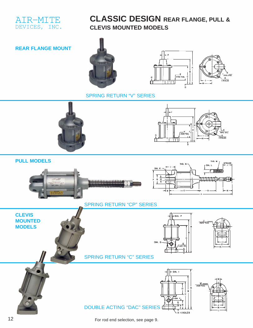
CLASSIC DESIGN REAR FLANGE, PULL &CLEVIS MOUNTED MODELS
REAR FLANGE MOUNT
PULL MODELS
CLEVIS MOUNTED MODELS
SPRING RETURN “V” SERIES
SPRING RETURN “CP” SERIES
SPRING RETURN “C” SERIES
DOUBLE ACTING “DAC” SERIES
13Please see page 42 in this catalog for full information on anti tie-down con-trols.
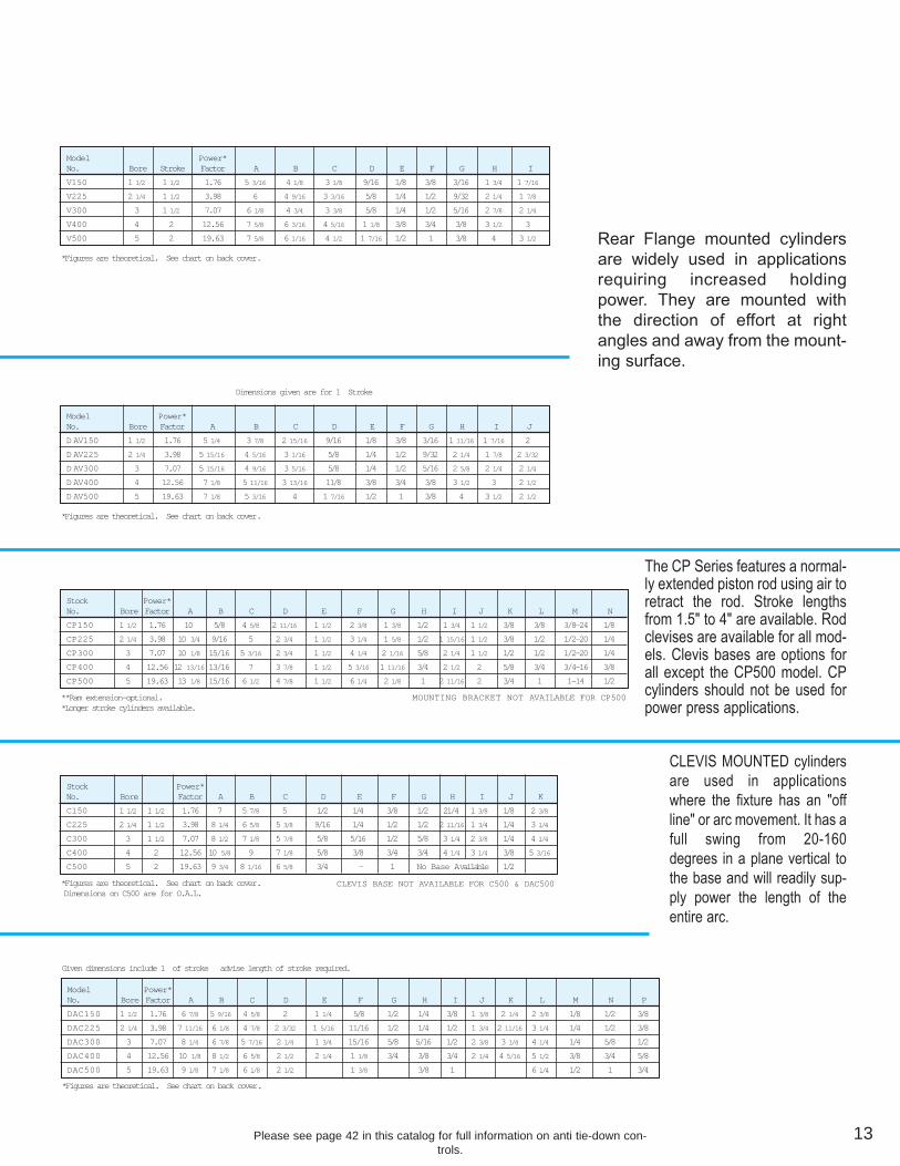
The CP Series features a normal-ly extended piston rod using air toretract the rod. Stroke lengthsfrom 1.5" to 4" are available. Rodclevises are available for all mod-els. Clevis bases are options forall except the CP500 model. CPcylinders should not be used forpower press applications.
CLEVIS MOUNTED cylindersare used in applicationswhere the fixture has an "offline" or arc movement. It has afull swing from 20-160degrees in a plane vertical tothe base and will readily sup-ply power the length of theentire arc.
Stock Power*No. Bore Factor A B C D E F G H I J K L M N
CP150 1 1/2 1.76 10 5/8 4 5/8 2 11/16 1 1/2 2 3/8 1 3/8 1/2 1 3/4 1 1/2 3/8 3/8 3/8-24 1/8
CP225 2 1/4 3.98 10 3/4 9/16 5 2 3/4 1 1/2 3 1/4 1 5/8 1/2 1 15/16 1 1/2 3/8 1/2 1/2-20 1/4
CP300 3 7.07 10 1/8 15/16 5 3/16 2 3/4 1 1/2 4 1/4 2 1/16 5/8 2 1/4 1 1/2 1/2 1/2 1/2-20 1/4
CP400 4 12.56 12 13/16 13/16 7 3 7/8 1 1/2 5 3/16 1 11/16 3/4 2 1/2 2 5/8 3/4 3/4-16 3/8
CP500 5 19.63 13 1/8 15/16 6 1/2 4 7/8 1 1/2 6 1/4 2 1/8 1 2 11/16 2 3/4 1 1-14 1/2
**Ram extension-optional.*Longer stroke cylinders available.
Stock Power*No. Bore Factor A B C D E F G H I J K
C150 1 1/2 1 1/2 1.76 7 5 7/8 5 1/2 1/4 3/8 1/2 21/4 1 3/8 1/8 2 3/8
C225 2 1/4 1 1/2 3.98 8 1/4 6 5/8 5 3/8 9/16 1/4 1/2 1/2 2 11/16 1 3/4 1/4 3 1/4
C300 3 1 1/2 7.07 8 1/2 7 1/8 5 7/8 5/8 5/16 1/2 5/8 3 1/4 2 3/8 1/4 4 1/4
C400 4 2 12.56 10 5/8 9 7 1/8 5/8 3/8 3/4 3/4 4 1/4 3 1/4 3/8 5 3/16
C500 5 2 19.63 9 3/4 8 1/16 6 5/8 3/4 - 1 No Base Available 1/2
*Figures are theoretical. See chart on back cover.Dimensions on C500 are for O.A.L.
Model Power*No. Bore Factor A B C D E F G H I J K L M N P
DAC150 1 1/2 1.76 6 7/8 5 9/16 4 5/8 2 1 1/4 5/8 1/2 1/4 3/8 1 3/8 2 1/4 2 3/8 1/8 1/2 3/8
DAC225 2 1/4 3.98 7 11/16 6 1/8 4 7/8 2 3/32 1 5/16 11/16 1/2 1/4 1/2 1 3/4 2 11/16 3 1/4 1/4 1/2 3/8
DAC300 3 7.07 8 1/4 6 7/8 5 7/16 2 1/4 1 3/4 15/16 5/8 5/16 1/2 2 3/8 3 1/4 4 1/4 1/4 5/8 1/2
DAC400 4 12.56 10 1/8 8 1/2 6 5/8 2 1/2 2 1/4 1 1/8 3/4 3/8 3/4 2 1/4 4 5/16 5 1/2 3/8 3/4 5/8
DAC500 5 19.63 9 1/8 7 1/8 6 1/8 2 1/2 1 3/8 3/8 1 6 1/4 1/2 1 3/4
*Figures are theoretical. See chart on back cover.
Given dimensions include 1 of stroke advise length of stroke required.
MOUNTING BRACKET NOT AVAILABLE FOR CP500
CLEVIS BASE NOT AVAILABLE FOR C500 & DAC500
Dimensions given are for 1 Stroke
Model Power*No. Bore Stroke Factor A B C D E F G H I
V150 1 1/2 1 1/2 1.76 5 3/16 4 1/8 3 1/8 9/16 1/8 3/8 3/16 1 3/4 1 7/16
V225 2 1/4 1 1/2 3.98 6 4 9/16 3 3/16 5/8 1/4 1/2 9/32 2 1/4 1 7/8
V300 3 1 1/2 7.07 6 1/8 4 3/4 3 3/8 5/8 1/4 1/2 5/16 2 7/8 2 1/4
V400 4 2 12.56 7 5/8 6 3/16 4 5/16 1 1/8 3/8 3/4 3/8 3 1/2 3
V500 5 2 19.63 7 5/8 6 1/16 4 1/2 1 7/16 1/2 1 3/8 4 3 1/2
*Figures are theoretical. See chart on back cover.
Model Power*No. Bore Factor A B C D E F G H I J
D AV150 1 1/2 1.76 5 1/4 3 7/8 2 15/16 9/16 1/8 3/8 3/16 1 11/16 1 7/16 2
D AV225 2 1/4 3.98 5 15/16 4 5/16 3 1/16 5/8 1/4 1/2 9/32 2 1/4 1 7/8 2 3/32
D AV300 3 7.07 5 15/16 4 9/16 3 5/16 5/8 1/4 1/2 5/16 2 5/8 2 1/4 2 1/4
D AV400 4 12.56 7 1/8 5 11/16 3 13/16 11/8 3/8 3/4 3/8 3 1/2 3 2 1/2
D AV500 5 19.63 7 1/8 5 3/16 4 1 7/16 1/2 1 3/8 4 3 1/2 2 1/2
*Figures are theoretical. See chart on back cover.
Rear Flange mounted cylindersare widely used in applicationsrequiring increased holdingpower. They are mounted withthe direction of effort at rightangles and away from the mount-ing surface.

14 Please see page 42 in this catalog for full information on anti tie-down con-trols.
AIR-MITEDEVICES, INC.
DAR cylinders offer space saving design formany types of fixtures and machinery. Uniquedesign permits complete interchangeability ofcylinders and accessories with those of similarround cylinder lines. Makes a simple fieldreplacement possible in existing or new applica-tions. Cylinders are available in both single and
double rod end styles. For all models, strokelengths of 1" thru 6" are ready to ship frominventory. Additional stroke lengths—asrequired.
Cylinders are assembled and shipped with portconfigurations as noted in above photos.
DAR CYLINDERS – AIR-150 PSIWATER/L.P. HYDRAULIC-250 PSI
DAR cylinders are available with in-port “ROTO-FLO” Speed Controls. See page 52 for further information.
Model BoreNo. Size P R S T U V W X Y Z A-A B-B C-C D-D E-E Z-Z
DAR10 1 1/8 5/8 15/32 7/8 2 1/4 9/32 1 3/4 2 1/4 1 3/4 3/8 1/4 1/8 3/4-16 3/8-16 1 5/16 1 1/4
DAR15 1 1/2 7/8 9/16 1 3/4 3 9/32 2 1/4 2 1/4 1 3/4 3/8 5/16 1/4 1-14 1/2-13 1 5/16 1 5/16
DAR20 2 7/8 9/16 1 3/4 3 9/32 2 1/4 2 1/4 1 3/4 3/8 5/16 1/4 1-14 5/8-11 1 5/16 1 5/16
DAR25 2 1/2 1 1/4 7/8 2 3/8 4 13/32 3 2 3/8 1 13/16 1/2 7/16 3/8 1 3/8-12 3/4-10 1 5/16 1 1/4 7/16
DAR30 3 1 1/4 7/8 2 3/8 4 13/32 3 2 3/8 1 13/16 1/2 7/16 3/8 1 3/8-12 3/4-10 1 5/16 1 1/4 7/16
DAR40 4 1 3/4 1 5/16 3 7/16 5 1 5/32 3 3/4 3 3/8 2 5/8 5/8 1/2 1/2 1 3/4-12 1-14 1 13/16 1 1/2 1/2
Model BoreNo. Size A B C D E F G H J K L M N O
DAR10 1 1/8 2 1/16 3/8 1 3/8 5/8 1 21/32 3/8 1 7/8 2 1/2 2 1 3/8 1 5/8 7/8
DAR15 1 1/2 2 5/8 1/2 1 3/4 7/8 1 1/4 7/8 1/2 1 1/2 1 1/4 3 1/4 2 1/2 1 9/32 1 5/8 1 1/16
DAR20 2 2 5/8 1/2 2 1/4 7/8 1 1/4 7/8 1/2 1 1/2 1 1/4 3 1/4 2 1/2 1 9/32 1 5/8 1 1/16
DAR25 2 1/2 2 7/8 9/16 2 3/4 1 2 1 3/8 5/8 1 11/16 1 1/2 4 1/2 3 3/8 1 29/32 2 1/4 1 3/8
DAR30 3 2 7/8 9/16 3 1/4 1 2 1 3/8 5/8 1 11/16 1 1/2 4 1/2 3 3/8 1 29/32 2 1/4 1 3/8
DAR40 4 4 7/8 13/16 4 1/4 1 1/8 2 3/16 1 7/16 3/4 2 1/4 1 7/8 5 1/4 4 2 17/32 3 1/4 1 3/4
NOTE: DAR10 cylinders available with oversize 7/8-14 mtg. threads BB -Advise.

15Please see page 42 in this catalog for full information on anti tie-down con-trols.
SPECIFICATIONSFront and Rear End Caps Anodized AluminumTubing Hard Coated AluminumPiston Rods Zinc or Chrome Plated Steel StainlessSteel optionalPiston Rods Threaded with Wrench Flats standardPiston Seal Buna N standard Viton Seals optionalDouble Rod Ends Available for all cylindersRemoval of Rear Tang OptionalSwivel of Rear Tang 90 Available for all cylinders
ROD END – OPTIONSType 1 PlainType 2 Full male thread (UNF)Type 2NC - Full male thread (UNC)Type 3 Shoulder and external male
threadType 4 Internal threadType 5 Per customer requirement
ROD EXTENSION Shown (See chart& drawing) Additional As required
SWIVEL BRACKET13911/8" BORE23911/2"-2" BORE33921/2"-3" BORE4394" BORE
ROD CLEVIS110 11/8" BORE14511/2" BORE2452" BORE34521/2"-3" BORE4454" BORE
110 3/8" x 16THREAD145 1/2" x 13THREAD245 5/8" x 11THREAD
FLANGE MOUNT12911/8" BORE22911/2" - 2" BORE32921/2"-3" BORE4294" BORE
FOOT MOUNT132A 11/8" BORE13211/2" BORE2322" BORE33221/2"-3" BORE4344" BORE
Basic Cylinder Dimensions

16
AIR-MITEDEVICES, INC.
MICRO MODELS – 3/4”, 1”, 11/8”, 11/4” BORES
SINGLE AND DOUBLE ACTING
SINGLE ACTING
“P” SERIESFOOT MOUNT
“V” SERIESNOSE MOUNT
DOUBLE ACTING
“DAP” SERIESFOOT MOUNT
“DAV” SERIESNOSE MOUNT

17
SPECIFICATIONS
V75, V100, V110,DAV75, DAV100 -Brass SeriesCylinder Body/Tube BrassCylinder Rods Zinc plated steel Stainless optional
Piston seals Buna N V-packsstandard Viton optional
Cylinder End Caps BrassOperating Pressures 0-150 psiAir 0-350 psi Hydraulic
Stroke lengths V75=1 thru 3"V100=1/2 thru 3" V110=1 thru3" D AV75= 1/2 thru 4"
D AV100=1 thru 6"Spring force Rate per inch: V100AC=7#; V100, V110-1=3.5#; V100 & V110-2, -3=2#
ROD END – OPTIONSType 1 Plain rod endType 2 External thread-see chart on back coverType 3 Shoulder and external threadType 4 Internal threadType 5 Cut off or flush shafts
SPECIFICATIONSV125, DAV125
Aluminum SeriesCylinder Body/Tube –
Anodized aluminumCylinder Rods–Zinc plated
steel Stainless–optionalPiston seals–V125–Buna N
V-packs DAV125–Buna N O-rings Viton v-packs andO-rings–optional
Cylinder EndCaps–Anodized aluminumOperating Pressures–0-150psi
Air 0-350 psi HydraulicStroke Lengths–V125=1/2
thru 1" DAV125=1 thru 3"Spring Force–Rate per inch
V125-1/2=15# V125-1=11#
ROD END – OPTIONSType 1 – Plain rod endType 2 – External thread-seechart on
back coverType 3 – Shoulder and external threadType 4 – Internal threadType 5 – Cut off or flush shaftsType 6 – Drill thru entire length of shaft
Stock Power*No. Bore Stroke Factor A B C D E F G H J K L M N
P-75-1/2 3/4 1/2 .44 2 3/4 1/2 2 3/4 1/2 -20 1 3/32 11/16 1 1/4 1 5/8 1/4 3/16 39/64 1/4
P-75-1 3/4 1 .44 3 1/4 1 2 1/2 3/4 1/2 -20 1 3/32 11/16 1 1/4 1 5/8 1/4 3/16 39/64 1/4
P-75-2 3/4 2 .44 4 61/64 2 4 13/64 3/4 1/2 -20 1 3/32 11/16 1 1/4 1 5/8 1/4 3/16 39/64 1/4
P-75-3 3/4 3 .44 5 61/64 3 5 13/64 3/4 1/2 -20 1 3/32 11/16 1 1/4 1 5/8 1/4 3/16 39/64 1/4
P-100 1 5/8 .75 2 11/16 5/8 2 3/16 1/2 5/8 -18 1 3/8 13/16 1 5/8 2 5/16 3/16 9/16 1/2
P-100-1 1 1 .75 3 9/16 1 2 9/16 3/4 5/8 -18 1 3/8 13/16 1 5/8 2 5/16 3/16 9/16 1/2
P-100-2 1 2 .75 5 1/2 2 4 1/2 1 5/8 -18 1 3/8 13/16 1 5/8 2 5/16 3/16 9/16 1/2
P-100-3 1 3 .75 6 1/2 3 5 1/2 1 5/8 -18 1 3/8 13/16 1 5/8 2 5/16 3/16 9/16 1/2
P-110-1 1 1/8 1 1.00 3 5/16 1 2 1/2 3/4 5/8 -18 1 15/32 13/16 1 5/8 2 5/16 3/16 9/16 1/2
P-110-2 1 1/8 2 1.00 5 13/16 2 4 3/8 1 5/8 -18 1 15/32 13/16 1 5/8 2 5/16 3/16 9/16 1/2
P-110-3 1 1/8 3 1.00 6 13/16 3 5 3/8 1 5/8 -18 1 15/32 13/16 1 5/8 2 5/16 3/16 9/16 1/2
P-1251/2 1 1/4 1/2 1.225 3 1/16 1/2 2 1 7/8 -14 1 5/8 27/32 1 5/8 2 3/8 3/16 5/8 1/2
P-125-1 1 1/4 1 1.225 3 1/2 1 2 1/2 1 7/8 -14 1 5/8 27/32 1 5/8 2 3/8 3/16 5/8 1/2
Stock Power*No. Bore Stroke Factor A B C D E F K L
V-75-1/2 3/4 1/2 .44 2 3/4 1/2 2 3/4 1/2 -20 7/8 1/4 3/8
V-75-1 3/4 1 .44 3 1/4 1 2 1/2 3/4 1/2 -20 7/8 1/4 3/8
V-75-2 3/4 2 .44 4 61/64 2 4 13/64 3/4 1/2 -20 7/8 1/4 3/8
V-75-3 3/4 3 .44 5 61/64 3 5 13/64 3/4 1/2 -20 7/8 1/4 3/8
V-100 1 5/8 .75 2 11/16 5/8 2 3/16 1/2 5/8 -18 1 1/4 5/16 5/8
V-100AC 1 5/8 .75 2 1/4 5/8 1 29/32 3/8 5/8 -18 1 1/4 5/16 3/8
V-100-1 1 1 .75 3 9/32 1 29/16 3/4 5/8 -18 1 1/4 5/16 5/8
V-100-2 1 2 .75 5 1/2 2 4 1/2 1 5/8 -18 1 1/4 5/16 5/8
V-100-3 1 3 .75 6 1/2 3 5 1/2 1 5/8 -18 1 1/4 5/16 5/8
V-110-1 1 1/8 1 1.00 3 5/16 1 2 1/2 3/4 5/8 -18 1 5/16 5/16 5/8
V-110-2 1 1/8 2 1.00 5 13/32 2 4 3/8 1 5/8 -18 1 5/16 5/16 5/8
V-110-3 1 1/8 3 1.00 6 13/32 3 5 3/8 1 5/8 -18 1 5/16 5/16 5/8
V-125-1/2 1 1/4 1/2 1.225 3 1/16 1/2 2 1 7/8 -14 1 1/2 3/8 5/8
V-125-1 1 1/4 1 1.225 3 1/2 1 2 1/2 1 7/8 -14 1 1/2 3/8 5/8
*Figures are theoretical. See chart on back cover.
Stock Power*No. Bore Stroke Factor A B C D E F G H J K L M N P
DAP75-1/2 3/4 1/2 .44 313/64 5/32 2 29/64 3/4 1/2 1 3/32 11/16 1 1/4 1 5/8 1/4 5/16 39/64 1/2 -20 3/16
DAP75-1 3/4 1 .44 3 23/32 5/32 2 51/64 3/4 1 1 3/32 11/16 1 1/4 1 5/8 1/4 5/16 39/64 1/2 -20 3/16
DAP75-2 3/4 2 .44 4 3/4 5/32 3 51/64 3/4 2 1 3/32 11/16 1 1/4 1 5/8 1/4 5/16 39/64 1/2 -20 3/16
DAP75-3 3/4 3 .44 5 23/32 5/32 4 51/64 3/4 3 1 3/32 11/16 1 1/4 1 5/8 1/4 5/16 39/64 1/2 -20 3/16
DAP75-4 3/4 4 .44 6 23/32 5/32 5 51/64 3/4 4 1 3/32 11/16 1 1/4 1 5/8 1/4 5/16 39/64 1/2 -20 3/16
DAP100-1/2 1 1/2 .75 3 3/16 3/16 2 1/2 1/2 1/2 1 1/4 5/8 1 5/8 2 5/16 3/8 9/16 7/8 -14 3/16
DAP100-1 1 1 .75 4 1/4 1/8 3 1/16 1 1/8 1 1 3/8 3/4 1 5/8 2 5/16 3/8 9/16 7/8 -14 3/16
DAP100-2 1 2 .75 5 3/8 1/8 4 1/16 1 1/8 2 1 3/8 3/4 1 5/8 2 5/16 3/8 9/16 7/8 -14 3/16
DAP100-3 1 3 .75 6 3/8 1/8 5 1/16 1 1/8 3 1 3/8 3/4 1 5/8 2 5/16 3/8 9/16 7/8 -14 3/16
DAP100-4 1 4 .75 7 3/8 1/8 6 1/16 1 1/8 4 1 3/8 3/4 1 5/8 2 5/16 3/8 9/16 7/8 -14 3/16
DAP100-5 1 5 .75 8 3/8 1/8 7 1/16 1 1/8 5 1 3/8 3/4 1 5/8 2 5/16 3/8 9/16 7/8 -14 3/16
DAP100-6 1 6 .75 9 3/8 1/8 8 1/16 1 1/8 6 1 3/8 3/4 1 5/8 2 5/16 3/8 9/16 7/8 -14 3/16
DAP125-1 1 1/4 1 1.22 4 5/8 1/8 3 3/8 1 1 1 21/32 7/8 1 5/8 2 3/8 1/2 5/8 7/8 3/16
DAP125-2 1 1/4 2 1.22 5 5/8 1/8 4 3/8 1 2 1 21/32 7/8 1 5/8 2 3/8 1/2 5/8 7/8 3/16
DAP125-3 1 1/4 3 1.22 6 5/8 1/8 5 3/8 1 3 1 21/32 7/8 1 5/8 2 3/8 1/2 5/8 7/8 3/16
Stock Power*No. Bore Stroke Factor A B C D E F G H J K
D AV75-1/2 3/4 1/2 .44 3 13/64 5/32 2 29/64 3/4 1/2 7/8 7/16 7/16 1/2 -20 1/4
D AV75-1 3/4 1 .44 3 45/64 5/32 2 61/64 3/4 1 7/8 7/16 7/16 1/2 -20 1/4
D AV-75-2 3/4 2 .44 4 45/64 5/32 3 61/64 3/4 2 7/8 7/16 7/16 1/2 -20 1/4
D AV75-3 3/4 3 .44 5 45/64 5/32 4 61/64 3/4 3 7/8 7/16 7/16 1/2 -20 1/4
D AV75-4 3/4 4 .44 6 23/32 5/32 5 61/64 3/4 4 7/8 7/16 7/16 1/2 -20 1/4
D AV100-1/2 1 1/2 .75 3 3/16 3/16 2 1/2 1/2 1/2 1 1/4 5/8 1/2 7/8 -14 5/16
D AV100-1 1 1 .75 4 1/4 1/8 3 1/16 1 1/8 1 1 1/4 5/8 1/2 7/8 -14 5/16
D AV100-2 1 2 .75 5 3/8 1/8 4 1/16 1 1/8 2 1 1/4 5/8 1/2 7/8 -14 5/16
D AV100-3 1 3 .75 6 3/8 1/8 5 1/16 1 1/8 3 1 1/4 5/8 1/2 7/8 -14 5/16
D AV100-4 1 4 .75 7 3/8 1/8 6 1/16 1 1/8 4 1 1/4 5/8 1/2 7/8 -14 5/16
D AV100-5 1 5 .75 8 3/8 1/8 7 1/16 1 1/8 5 1 1/4 5/8 1/2 7/8 -14 5/16
D AV100-6 1 6 .75 9 3/8 1/8 8 1/16 1 1/8 6 1 1/4 5/8 1/2 7/8 -14 5/16
D AV125-1 1 1/4 1 1.22 4 5/8 1/8 3 3/8 1 1 1 1/2 5/8 5/8 7/8 -14 3/8
D AV125-2 1 1/4 2 1.22 5 5/8 1/8 4 3/8 1 2 1 1/2 5/8 5/8 7/8 -14 3/8
D AV125-3 1 1/4 3 1.22 6 5/8 1/8 5 3/8 1 3 1 1/2 5/8 5/8 7/8 -14 3/8
*Figures are theoretical. See chart on back cover.
Micro model cylinders are “bantam” cylinders designed specifically for limited space applications.Single and double acting models provide ample power for many applications: clamping, locking,ejection, throttling are but a few. Controlled singly or in groups, all cylinders are repairable andeasily repaired or replaced in the field.
18
AIR-MITEDEVICES, INC.
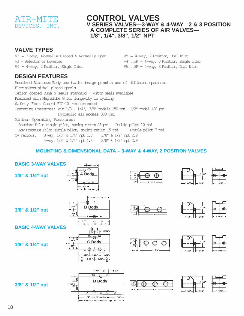
CONTROL VALVES V SERIES VALVES—3-WAY & 4-WAY 2 & 3 POSITION
A COMPLETE SERIES OF AIR VALVES—1/8", 1/4", 3/8", 1/2" NPT
VALVE TYPESV3 = 3-way, Normally Closed & Normally OpenV3 = Selector or Diverter V4 = 4-way, 2 Position, Single Inlet
V5 = 4-way, 2 Position, Dual InletV4...3P = 4-way, 3 Position, Single InletV5...3P = 4-way, 3 Position, Dual Inlet
DESIGN FEATURESAnodized Aluminum Body one basic design permits use of different operators Electroless nickel plated spoolsTeflon coated Buna N seals standard Viton seals availablePrelubed with Magnalube G for longevity in cyclingSafety Foot Guard FG100 recommendedOperating Pressures: Air 1/8", 1/4", 3/8" models 150 psi 1/2" model 120 psi
Hydraulic all models 300 psiMinimum Operating Pressures:Standard Pilot single pilot, spring return 25 psi Double pilot 10 psiLow Pressure Pilot single pilot, spring return 15 psi Double pilot 7 psi
Cv Factors: 3-way: 1/8" & 1/4" npt 1.8 3/8" & 1/2" npt 2.94-way: 1/8" & 1/4" npt 1.8 3/8" & 1/2" npt 2.9
MOUNTING & DIMENSIONAL DATA – 3-WAY & 4-WAY, 2 POSITION VALVES
BASIC 3-WAY VALVES
1/8" & 1/4" npt
3/8" & 1/2" npt
BASIC 4-WAY VALVES
1/8" & 1/4" npt
3/8" & 1/2" npt
A Body
B Body
C Body
D Body

MOUNTING & DIMENSIONAL DATA – 4-WAY, 3 POSITION VALVESSpring to center or detented, closed center or open center
19Please see page 42 in this catalog for full information on anti tie-down con-trols.
ORDERING INFORMATIONV SERIES - MODEL NUMBERS (4 Digits)
Photos & drawings of our most frequently used control valves see pp. 20-29.
1st Digit 2nd Digit 3rd & 4th Digit
Type Port Size Actuator/Return-2 positionV3 = 3-Way 1 = 1/8" npt 00 = Basic/Spring 08 = Pedal/SpringV4 = 4-Way-2 pos. 2 = 1/4" npt 01 = Palm Button/Manual09 = Treadle/ManualV5 = 4 Way-2 pos./Dual Inlet 3 = 3/8" npt 02 = Palm Button/Spring 10 = Treadle/SpringV4...3P = 4 Way-3 pos. 4 = 1/2" npt 03 = Handball/Manual 11 = Roller Cam/SpringV5...3P = 4 Way-3 pos. 04 = Handball/Spring 12 = Ball Cam/Spring
06 = Finger Tip/Spring 15 = Double Pilot16 = Single Pilot
V4 2 10
Example: V4210 = 4-Way, 2 pos. 1/4" single inlet treadle w/spring return.
Note: Modifications & some custom valve numbers can be created by combining primary model numberswith many of the below noted primary modifications.
PRIMARY MODIFICATIONS - 2 & 3 POSITION VALVES
Manual Control Valve Suffixes - 2 Position Valves
A = Special mtg holes LP - Low pressure pilot S = Selector valve
D = Detent NO = Normally open T = Light duty spring
G = Heavy duty spring P = Pilot return V = Viton seals
H = Hydraulic (Low Pressure) PM = Panel mount X = X201 mufflers in ports
HD = Heavy duty actuator R = Diverter valve Y = Shorter hand ball assy. 3 OAL
Manual Control Valve Suffixes 3 Position Valves
-To order 3 position valves, add the following suffix to 4-way, 2 pos. primary valve numbers
3P = 3 position, closed center, spring to center 3PD = 3 position, closed center, detented
3PO = 3 position, open center, spring to center 3POD = 3 position, open center, detented
D BodyC Body
1/8" & 1/4" npt 3/8" & 1/2" npt

20
AIR-MITEDEVICES, INC.
V3 SERIES 3-WAY CONTROL VALVESNORMALLY CLOSED & NORMALLY OPEN
3-WAY PALM BUTTON
3-WAY PALM BUTTON-PILOT RETURN
3-WAY PANEL MOUNT
3-WAY PANEL MOUNT-PILOT RETURN
MANUAL RETURN
PILOTRETURN
SPRINGRETURN
DETENT-
V3101 1/8", V3201 1/4"NPT
(Manual Return)V3102 1/8", V3202 1/4"
V3301 3/8", V3401 1/2"NPT
(Manual Return)V3302 3/8", V3402 1/2"
V3101P 1/8", V3201P 1/4"NPT
V3301P 3/8", V3401P 1/2"NPT
V3301-PM 3/8" (M)V3302-PM 3/8" (S)
V3401-PM 1/2" (M)V3402-PM 1/2" (S)
3-WayV3101-PM 1/8"(Manual)
V3102-PM 1/8"(Spring)
V3301-PMP 3/8" (PR)V3401-PMP 1/2" (PR)
V3101-PMP 1/8" (PilotReturn)
For Heavy Duty Actuators & Detented Actuators see p. 19 for “HD” & “D” suffixes.
MANUAL RETURN
SPRINGRETURN
DETENT-
PILOTRETURN

21
MANUALRETURN
SPRINGRETURN
DETENT-
SPRINGRETUR
PILOTRETURN
3-WAY HAND BALL VALVE
3-WAY FINGER VALVE
3-WAY PEDAL VALVE
3-WAY PEDAL-PILOT RETURN
V3103 1/8", V3203 1/4"NPT
(Manual Return)V3104 1/8", V3204 1/4"
V3303 3/8", V3403 1/2"NPT
(Manual Return)V3304 3/8", V3404 1/2"
V3106 1/8", V3206 1/4"NPT
V3306 3/8", V3406 1/2"NPT
V3108 1/8", V3208 1/4"NPT
V3308 3/8", V3408 1/2"NPT
V3108P1/8", V3208P1/4" V3308P3/8", V3408P1/2"
To order as Normally Open valves—add NO suffix to part numbers
*For peak efficiency lubrication of thevalve is recommended.
W ARNING: All hand and foot operated valves should be guarded to prevent accidental orunintended operation in accordance with OSHA Section 1910.217 and AISSection B11.1.
SPRINGRETURN

22 For Heavy Duty Actuators & Detented Actuators see p. 19 for “HD” & “D” suffixes.
AIR-MITEDEVICES, INC.
V3 SERIES 3-WAY CONTROL VALVESNORMALLY CLOSED & NORMALLY OPEN 1/8", 1/4", 3/8", 1/2" NPT
3-WAY TREADLE VALVE
3-WAY ROLLER CAM
3-WAY ROLLER CAM-PILOT RETURN
3-WAY BALL CAM
M A N U-AL
SPRINGRETUR
DETENT-
V3109 1/8", V3209 1/4"NPT
(Manual Return)V3110 1/8", V3210 1/4" NPT
V3309 3/8", V3409 1/2"NPT
(Manual Return)V3310 3/8", V3410 1/2"
V3111 1/8", V3211 1/4" NPT(Spring Return)
V3311 3/8", V3411 1/2" NPT(Spring Return)
V3111P 1/8", V3211P 1/4"NPT
V3311P 3/8", V3411P 1/2"NPT
V3112 1/8", V3212 1/4" NPT(Spring Return)
V3312 3/8", V3412 1/2"NPT
SPRINGRETURN
PILOTRETURN
SPRINGRETURN

23
AIR-MITEDEVICES, INC.
V4 & V5 SERIES 4-WAY CONTROL VALVES2 POSITION SINGLE & DUAL INLET 1/8", 1/4", 3/8", 1/2" NPT
4-WAY PALM BUTTONVALVE
4-WAY PALM BUTTON-PILOT RETURN
4-WAY PANEL MOUNT VALVE
4-WAY PANEL MOUNT-PILOT RETURN
PILOTRETURN
V4301 3/8", V4401 1/2"NPTV5301 3/8", V5401 1/2"
NPT(Manual Return)
V4302 3/8", V4402 1/2"
V4101 1/8", V4201 1/4"NPTV5101 1/8", V5201 1/4"
NPT(Manual Return)
V4102 1/8", V4202 1/4"
V4301P 3/8", V4401P 1/2"NPTV5301P 3/8", V5401P 1/2"
V4101P 1/8", V4201P 1/4"NPTV5101P 1/8", V5201P 1/4"
V4301-PM 3/8" (M)V4302-PM 3/8" (S)
V4401-PM 1/2" (M)V4402-PM 1/2" (S)
V4101-PM 1/8(Manual)
V4102-PM 1/8 (Spring)
V4301-PMP 3/8" V4401-PMP 1/2"V4101-PMP 1/8 V4201-PMP 1/4" P = Pilot (Air) Return
For Heavy Duty Actuators & Detented Actuators see p. 19 for “HD” & “D” suffixes.
MANUALRETURN
SPRINGRETURN
DETENTED
PILOTRETURN
MANUALRETURN
SPRINGRETURN
DETENTED

SPRINGRETURN
SPRINGRETURN
PILOTRETURN
V4103 1/8", V4203 1/4"NPTV5103 1/8", V5203 1/4"
NPT(Manual Return)
V4104 1/8", V4204 1/4"
NPTV5104 1/8", V5204 1/4"NPT
(Spring Return)V4303 3/8", V4403 1/2"NPT
V4306 3/8", V4406 1/2"NPTV5306 3/8", V5406 1/2"
V4106 1/8", V4206 1/4"NPTV5106 1/8", V5206 1/4"
V4308 3/8", V4408 1/2"NPTV5308 3/8", V5408 1/2"
V4108 1/8", V4208 1/4"NPTV5108 1/8", V5208 1/4"
V4108P 1/8"NPT
V5108P 1/8"NPT
V4208P 1/4"NPT
V5208P 1/4"NPT
24
AIR-MITEDEVICES, INC.
V4 & V5 SERIES 4-WAY CONTROL VALVES2 POSITION SINGLE & DUAL INLET 1/8", 1/4", 3/8", 1/2" NPT
4-WAY HAND BALL VALVE
4-WAY FINGER VALVE
4-WAY PEDAL VALVE
4-WAY PEDAL-PILOT RETURN VALVE
For Heavy Duty Actuators & Detented Actuators see p. 19 for “HD” & “D” suffixes.
MANUALRETURN
SPRINGRETURN
DETENT-

25
V4109 1/8", V4209 1/4"NPTV5109 1/8", V5209 1/4"
NPT(Manual Return)
V4110 1/8", V4210 1/4"
NPTV5110 1/8", V5210 1/4"NPT
(Spring Return)V4309 3/8", V4409 1/2"NPT
V4311 3/8", V4411 1/2"NPTV5311 3/8", V5411 1/2"
V4111 1/8", V4211 1/4"NPTV5111 1/8", V5211 1/4"
PILOTRETURN
V4312 3/8", V4412 1/2"NPTV5312 3/8", V5412 1/2"
V4112 1/8", V4212 1/4"NPTV5112 1/8", V5212 1/4"
W ARNING: All hand and foot operated valves should be guarded to prevent acci-dental or unintended operation in accordance with OSHA Section 1910.217 andAIS Section B11.1.
4-WAY TREADLE VALVE
4-WAY ROLLER CAM VALVE
4-WAY ROLLER CAM-PILOT RETURN
4-WAY BALL CAM VALVE
For Heavy Duty Actuators & Detented Actuators see p. 19 for “HD” & “D” suffixes.
SPRINGRETURN
SPRINGRETURN
MANUALRETURN
SPRINGRETURN
DETENT-
V4311P 3/8", V4411P 1/2"NPT
V4111P 1/8", V4211P 1/4"NPT
NOTE: For open center models, consult ordering information on page 19.26
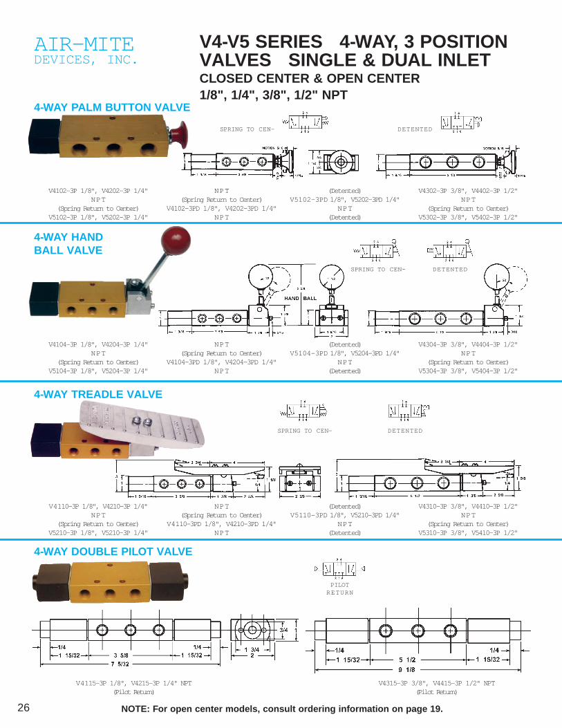
AIR-MITEDEVICES, INC.
V4-V5 SERIES 4-WAY, 3 POSITIONVALVES SINGLE & DUAL INLETCLOSED CENTER & OPEN CENTER 1/8", 1/4", 3/8", 1/2" NPT
4-WAY PALM BUTTON VALVE
4-WAY HAND BALL VALVE
4-WAY TREADLE VALVE
4-WAY DOUBLE PILOT VALVE
V4102-3P 1/8", V4202-3P 1/4"NPT
(Spring Return to Center)V5102-3P 1/8", V5202-3P 1/4"
NPT(Spring Return to Center)
V4102-3PD 1/8", V4202-3PD 1/4"NPT
(Detented)V5102-3PD 1/8", V5202-3PD 1/4"
NPT(Detented)
V4302-3P 3/8", V4402-3P 1/2"NPT
(Spring Return to Center)V5302-3P 3/8", V5402-3P 1/2"
SPRING TO CEN-
V4104-3P 1/8", V4204-3P 1/4"NPT
(Spring Return to Center)V5104-3P 1/8", V5204-3P 1/4"
NPT(Spring Return to Center)
V4104-3PD 1/8", V4204-3PD 1/4"NPT
(Detented)V5104-3PD 1/8", V5204-3PD 1/4"
NPT(Detented)
V4304-3P 3/8", V4404-3P 1/2"NPT
(Spring Return to Center)V5304-3P 3/8", V5404-3P 1/2"
V4110-3P 1/8", V4210-3P 1/4"NPT
(Spring Return to Center)V5210-3P 1/8", V5210-3P 1/4"
NPT(Spring Return to Center)
V4110-3PD 1/8", V4210-3PD 1/4"NPT
(Detented)V5110-3PD 1/8", V5210-3PD 1/4"
NPT(Detented)
V4310-3P 3/8", V4410-3P 1/2"NPT
(Spring Return to Center)V5310-3P 3/8", V5410-3P 1/2"
V4315-3P 3/8", V4415-3P 1/2" NPT(Pilot Return)
V4115-3P 1/8", V4215-3P 1/4" NPT(Pilot Return)
DETENTED
SPRING TO CEN- DETENTED
SPRING TO CEN- DETENTED
PILOTRETURN
27Please see page 42 in this catalog for full information on anti tie-down con-trols.
AIR-MITEDEVICES, INC.
SAFETY FOOT GUARD - FG100
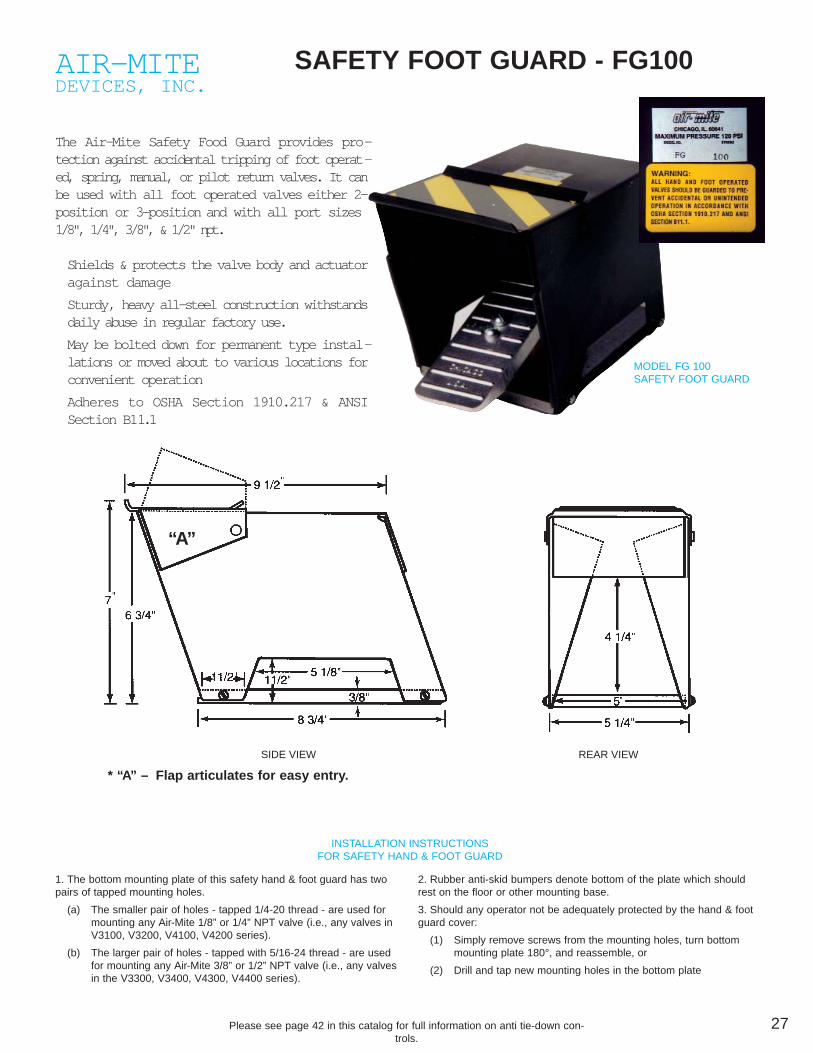
The Air-Mite Safety Food Guard provides pro-tection against accidental tripping of foot operat-ed, spring, manual, or pilot return valves. It canbe used with all foot operated valves either 2-position or 3-position and with all port sizes1/8", 1/4", 3/8", & 1/2" npt.
Shields & protects the valve body and actuatoragainst damage
Sturdy, heavy all-steel construction withstandsdaily abuse in regular factory use.
May be bolted down for permanent type instal-lations or moved about to various locations forconvenient operation
Adheres to OSHA Section 1910.217 & ANSISection B11.1
MODEL FG 100SAFETY FOOT GUARD
INSTALLATION INSTRUCTIONSFOR SAFETY HAND & FOOT GUARD
SIDE VIEW REAR VIEW
1. The bottom mounting plate of this safety hand & foot guard has twopairs of tapped mounting holes.
(a) The smaller pair of holes - tapped 1/4-20 thread - are used formounting any Air-Mite 1/8” or 1/4” NPT valve (i.e., any valves inV3100, V3200, V4100, V4200 series).
(b) The larger pair of holes - tapped with 5/16-24 thread - are usedfor mounting any Air-Mite 3/8” or 1/2” NPT valve (i.e., any valvesin the V3300, V3400, V4300, V4400 series).
2. Rubber anti-skid bumpers denote bottom of the plate which shouldrest on the floor or other mounting base.
3. Should any operator not be adequately protected by the hand & footguard cover:
(1) Simply remove screws from the mounting holes, turn bottommounting plate 180°, and reassemble, or
(2) Drill and tap new mounting holes in the bottom plate
“A”
* “A” – Flap articulates for easy entry.
28 Please see page 42 in this catalog for full information on anti tie-down con-trols.
AIR-MITEDEVICES, INC.
V3-V4 SERIES PILOT VALVES 3-WAY & 4-WAY, 2-POSITIONSINGLE & DOUBLE PILOT
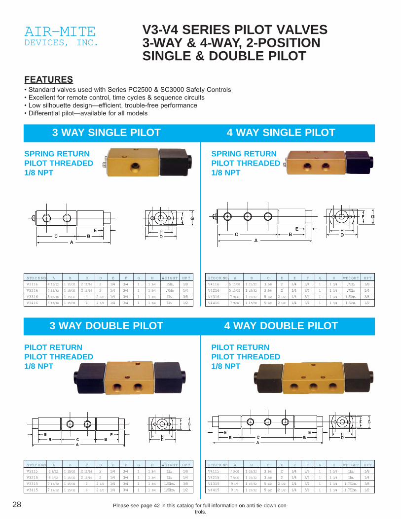
FEATURES• Standard valves used with Series PC2500 & SC3000 Safety Controls• Excellent for remote control, time cycles & sequence circuits• Low silhouette design—efficient, trouble-free performance• Differential pilot—available for all models
3 WAY SINGLE PILOT 4 WAY SINGLE PILOT
3 WAY DOUBLE PILOT 4 WAY DOUBLE PILOT
SPRING RETURNPILOT THREADED1/8 NPT
SPRING RETURNPILOT THREADED1/8 NPT
PILOT RETURNPILOT THREADED1/8 NPT
PILOT RETURNPILOT THREADED1/8 NPT
STO C K NO. A B C D E F G H WEIGHT HPT
V3116 4 15/32 1 15/32 2 11/16 2 1/4 3/4 1 1 3/4 .75lb. 1/8
V3216 4 15/32 1 15/32 2 11/16 2 1/4 3/4 1 1 3/4 .75lb 1/4
V3316 5 13/16 1 15/32 4 2 1/2 1/4 3/4 1 1 3/4 1lb. 3/8
V3416 5 13/16 1 15/32 4 2 1/2 1/4 3/4 1 1 3/4 1lb. 1/2
STO C K NO. A B C D E F G H WEIGHT HPT
V4116 5 13/32 1 15/32 3 5/8 2 1/4 3/4 1 1 3/4 .75lb. 1/8
V4216 5 13/32 1 15/32 3 5/8 2 1/4 3/4 1 1 3/4 .75lb. 1/4
V4316 7 9/32 1 15/32 5 1/2 2 1/2 1/4 3/4 1 1 3/4 1.5lbs. 3/8
V4416 7 9/32 1 15/32 5 1/2 2 1/2 1/4 3/4 1 1 3/4 1.5lbs. 1/2
STO C K NO. A B C D E F G H WEIGHT HPT
V3115 6 9/32 1 15/32 2 11/16 2 1/4 3/4 1 1 3/4 1lb. 1/8
V3215 6 9/32 1 15/32 2 11/16 2 1/4 3/4 1 1 3/4 1lb. 1/4
V3315 7 19/32 1 15/32 4 2 1/2 1/4 3/4 1 1 3/4 1.5lbs. 3/8
V3415 7 19/32 1 15/32 4 2 1/2 1/4 3/4 1 1 3/4 1.5lbs. 1/2
STO C K NO. A B C D E F G H WEIGHT HPT
V4115 7 5/32 1 15/32 3 5/8 2 1/4 3/4 1 1 3/4 1lb. 1/8
V4215 7 5/32 1 15/32 3 5/8 2 1/4 3/4 1 1 3/4 1lb. 1/4
V4315 9 1/8 1 15/32 5 1/2 2 1/2 1/4 3/4 1 1 3/4 1.75lbs. 3/8
V4415 9 1/8 1 15/32 5 1/2 2 1/2 1/4 3/4 1 1 3/4 1.75lbs. 1/2
29Please see page 42 in this catalog for full information on anti tie-down con-trols.
AIR-MITEDEVICES, INC.
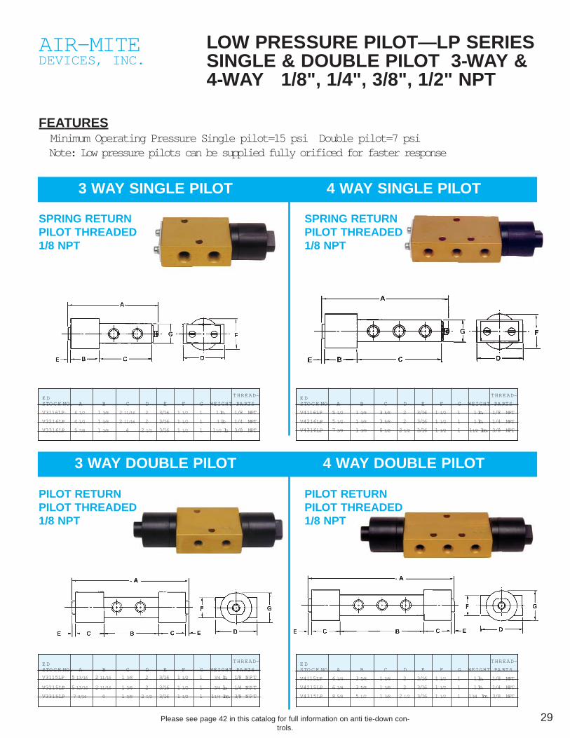
LOW PRESSURE PILOT—LP SERIESSINGLE & DOUBLE PILOT 3-WAY &4-WAY 1/8", 1/4", 3/8", 1/2" NPT
FEATURES Minimum Operating Pressure Single pilot=15 psi Double pilot=7 psi Note: Low pressure pilots can be supplied fully orificed for faster response
3 WAY SINGLE PILOT 4 WAY SINGLE PILOT
3 WAY DOUBLE PILOT 4 WAY DOUBLE PILOT
SPRING RETURNPILOT THREADED1/8 NPT
SPRING RETURNPILOT THREADED1/8 NPT
PILOT RETURNPILOT THREADED1/8 NPT
PILOT RETURNPILOT THREADED1/8 NPT
THREAD-E DSTO C K NO. A B C D E F G WEIGHT PA RTS
V3116LP 4 1/2 1 3/8 2 11/16 2 3/16 1 1/2 1 1 lb. 1/8 NPT
V3216LP 4 1/2 1 3/8 2 11/16 2 3/16 1 1/2 1 1 lb 1/4 NPT
V3316LP 5 7/8 1 3/8 4 2 1/2 3/16 1 1/2 1 11/2 lb. 3/8 NPT
THREAD-E DSTO C K NO. A B C D E F G WEIGHT PA RTS
V4116LP 5 1/2 1 3/8 3 5/8 2 3/16 1 1/2 1 1 lb. 1/8 NPT
V4216LP 5 1/2 1 3/8 3 5/8 2 3/16 1 1/2 1 1 lb. 1/4 NPT
V4316LP 7 3/8 1 3/8 5 1/2 2 1/2 3/16 1 1/2 1 11/2 lbs. 3/8 NPT
THREAD-E DSTO C K NO. A B C D E F G WEIGHT PA RTS
V3115LP 5 13/16 2 11/16 1 3/8 2 3/16 1 1/2 1 3/4 lb. 1/8 NPT
V3215LP 5 13/16 2 11/16 1 3/8 2 3/16 1 1/2 1 3/4 lb. 1/4 NPT
V3315LP 7 3/16 4 1 3/8 2 1/2 3/16 1 1/2 1 11/4 lbs. 3/8 NPT
THREAD-E DSTO C K NO. A B C D E F G WEIGHT PA RTS
V4115LP 6 1/4 3 5/8 1 3/8 2 3/16 1 1/2 1 1 lb. 1/8 NPT
V4215LP 6 1/4 3 5/8 1 3/8 2 3/16 1 1/2 1 1 lb. 1/4 NPT
V4315LP 8 5/8 5 1/2 1 3/8 2 1/2 3/16 1 1/2 1 13/4 lbs. 3/8 NPT

30
AIR-MITEDEVICES, INC.
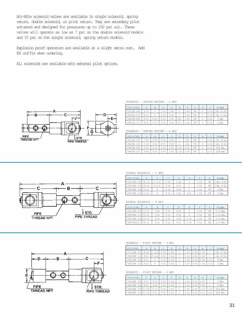
V3 & V4 SERIES 3-WAY & 4-WAYSOLENOID VALVES SINGLE & DOUBLE SOLENOID1/8", 1/4", 3/8" & 1/2" NPT
FEATURESModels: 3-Way Normally closed & Normally open
4-Way Single inlet, 2 position
Internally piloted valvesOperating Pressures: Single solenoid, spring ret 15-150psi
Double solenoid 7-150psiTeflon coated Buna N SealsElectroless nickel spoolsStandard coils 120/60 & 240/60 many other voltages in stockExplosion proof operators & high temp coils in stock
SPRING RETURN SOLENOID VALVE
DOUBLE SOLENOID VALVE
PILOT RETURN SOLENOID VALVE
31
Air-Mite solenoid valves are available in single solenoid, springreturn, double solenoid, or pilot return. They are secondary pilotactuated and designed for pressures up to 150 psi air. Thesevalves will operate as low as 7 psi on the double solenoid modelsand 15 psi on the single solenoid, spring return models.
Explosion proof operators are available at a slight extra cost. AddEX suffix when ordering.
All solenoids are available with external pilot options.
STOCK NO. A B C D E F G H J W eight
V3113SP 1/8 8 1/8 2 11/16 3 7/8 1 9/16 1 1 1/8 2 5/8 1 5/8 1 1 Lb. 12 Oz.
V3213SP 1/4 8 1/8 2 11/16 3 7/8 1 9/16 1 1 1/8 2 5/8 1 5/8 1 1 Lb. 12 Oz.
V3313SP 3/8 9 1/2 4 3 7/8 1 9/16 1 1 1/8 2 5/8 1 5/8 1 1/4 2 Lbs.
V3413SP 1/2 9 1/2 4 3 7/8 1 9/16 1 1 1/8 2 5/8 1 5/8 1 1/4 2 Lbs.
STO C K NO. A B C D E F G H J W eight
V4114SP 1/8 9 1/8 3 5/8 3 7/8 1 9/16 1 1 1/8 2 5/8 1 5/8 1 2 Lbs.
V4214SP 1/4 9 1/8 3 5/8 3 7/8 1 9/16 1 1 1/8 2 5/8 1 5/8 1 2 Lbs.
V4314SP 3/8 11 1/16 5 1/2 3 7/8 1 9/16 1 1 1/8 2 5/8 1 5/8 1 1/4 21/2 Lbs.
V4414SP 1/2 11 1/16 5 1/2 3 7/8 1 9/16 1 1 1/8 2 5/8 1 5/8 1 1/4 21/2 Lbs.
STO C K NO. A B C D E F G H J W eight
V3113S 1/8 6 7/8 3 3 7/8 2 5/8 1 1 5/8 7/8 1 1 1/8 1 Lb. 11 Oz.
V3213S 1/4 6 7/8 3 3 7/8 2 5/8 1 1 5/8 7/8 1 1 1/8 1 Lb. 11 Oz.
V3313S 3/8 8 1/8 4 1/4 3 7/8 2 5/8 11/4 1 5/8 7/8 1 1 1/8 2 Lbs.
V3413S 1/2 8 1/8 4 1/4 3 7/8 2 5/8 11/4 1 5/8 7/8 1 1 1/8 2 Lbs.
SOLENOID - PILOT RETURN - 3 WAY
SOLENOID - PILOT RETURN - 4 WAY
SOLENOID - SPRING RETURN - 3 WAY
STO C K NO. A B C D E F G H J W eight
V4114S 1/8 7 3/4 3 7/8 3 7/8 2 5/8 1 15/8 7/8 1 1 1/8 1 Lb. 13 Oz.
V4214S 1/4 7 3/4 3 7/8 3 7/8 2 5/8 1 15/8 7/8 1 1 1/8 1 Lb. 13 Oz.
V4314S 3/8 9 3/4 5 3/4 3 7/8 2 5/8 1 1/4 1 5/8 7/8 1 1 1/8 21/4 Lbs.
V4414S 1/2 9 3/4 5 3/4 3 7/8 2 5/8 1 1/4 1 5/8 7/8 1 1 1/8 21/4 Lbs.
STO C K NO. A B C D E F G W eight
V3113SS 1/8 10 1/2 2 11/16 3 7/8 2 5/8 1 1 5/8 7/8 2 Lbs. 6 Oz.
V3213SS 1/4 10 1/2 2 11/16 3 7/8 2 5/8 1 1 5/8 7/8 2 Lbs. 6 Oz.
V3313SS 3/8 11 3/4 4 3 7/8 2 5/8 1 1 5/8 7/8 3 Lbs.
V3413SS 1/2 11 3/4 4 3 7/8 2 5/8 11/4 1 5/8 7/8 3 Lbs.
STO C K NO. A B C D E F G W eight
V4114SS 1/8 11 1/2 3 5/8 3 7/8 2 5/8 1 1 5/8 7/8 2 1/2 Lbs.
V4214SS 1/4 11 1/2 3 5/8 3 7/8 2 5/8 1 1 5/8 7/8 2 1/2 Lbs.
V4314SS 3/8 13 1/2 5 1/2 3 7/8 2 5/8 1 1/4 1 5/8 7/8 3 1/4 Lbs.
V4414SS1/2 13 1/2 5 1/2 3 7/8 2 5/8 1 1/4 1 5/8 7/8 3 1/4 Lbs.
SOLENOID - SPRING RETURN - 4 WAY
DOUBLE SOLENOID - 3 WAY
DOUBLE SOLENOID - 4 WAY

32
AIR-MITEDEVICES, INC.
S2 & S3 SERIES 2-WAY & 3-WAY1/8" & 1/4" NPT PORTSNORMALLY CLOSED & NORMALLY OPEN
2 WAYMODEL S 2-WAY NORMALLY CLOSED
MODEL SO 2-WAY NORMALLY OPEN
3 WAYMODEL S 3-WAY EXHAUST TO ATMOSPHERE
MODEL S, SO, SD, SM 3-WAYWITH PIPED EXHAUST
MODEL S VALVE SPECIFICATIONSTwo-way normally closed or normally open solenoid valves for air, steam, gas,water and oil. General purpose or safety application.Leakage: bubble tightTemperature: -45°F up to +185°F media and +77°F ambientOperating speed: 600 CPM maxLife expectancy: millions of cycles depending on application, lubrication, etc.Power consumption: 10 wattsDuty cycles: continuous or intermittentMaterial: body and interior parts are stainless steelCoil currents: In Rush—260 milliampsBurst pressure: 6000psi
MODEL S, SO, SD, SM VALVE SPECIFICATIONSThree-way solenoid valves for air, steam, gas, water and oil. General purposeor safety application.Leakage: bubble tightTemperature: -45°F up to +185°F media and +77°F ambientOperating speed: 600 CPM maxLife expectancy: millions of cycles depending on application, lubrication, etc.Power consumption: 10 wattsDuty cycles: continuous or intermittentMaterial: body and interior parts are stainless steelBurst pressure: 6000psi

33
Air-Mite Two- and Three-Way Solenoid valves aredesigned for air, steam, gas, water and oil in generalpurpose and safety use. Valves are bubble tight andhave a built-in safety factor against leakage. Canoperate at less than rated voltage when full pressureis applied. DIN connectors and/or Viton seals avail-able upon request.
MAX. PRESSURE DIFF. PSI CONDUIT HOUSING FLOW
A.C. D.C. ORIFICE SIZE CV FACTO R 1/8 NPT PORTS 1/4 NPT PORTS DE-ENERGIZED ENERGIZED
MODEL S- 250 250 3/64 .052 S2110 S2210
2-WAY 200 200 1/16 .095 S2120 S2220
NORMALLY 125 125 3/32 .156 S2130 S2230
CLOSED 100 100 1/8 .214 S2140 S2240
VALVES 75 50 5/32 .404 S2150 S2250
50 25 3/16 .500 S2160 S2260
MAX.PRESS.DIFF. PSI ORIFICE SIZE CV FACTO R CONDUIT HOUSING FLOW
A.C. OR D.C. INLET INCHEXHAUST INCHINLET EXHAUST1/8 NPT PORTS1/4 NPT PORTS DE-ENERGIZED ENER-
GIZED
MODEL S- 150 3/64 1/16 .052 .095 S3112 S3212
3-WAY 100 1/16 1/16 .095 .095 S3122 S3222
NORMALLY 75 3/32 3/32 .156 .156 S3133 S3233
CLOSED VALVES 50 1/8 3/32 .216 .156 S3143 S3243
-EXHAUST TO 20 3/16 3/32 .500 .156 S3163 S3263
ATMOSPHERE
MODEL S- 150 3/64 1/16 .052 .095 S3112E S3212F
3-WAY 100 1/16 1/16 .095 .095 S3122E S3222F
NORMALLY 75 3/32 3/32 .156 .156 S3133E S3233F
CLOSED 50 1/8 3/32 .214 .156 S3143E S3243F
VALVES- 20 3/16 3/32 .500 .156 S3163E S3263F
PIPED EXHAUST
MODEL SO - 150 3/64 1/16 .052 .095 SO3112 SO3212
3-WAY 100 1/16 1/16 .095 .095 SO3122 SO3222
NORMALLY 75 3/32 1/8 .156 .214 SO3134 SO3234
OPEN VALVES
MODEL SD - 235 3/64* 3/64 .052* .052 SD3111 SD3211
DIRECTIONAL 200 1/16* 3/64 .095* .052 SD3121 SD3221
CONTROL 150 1/16* 1/16 .095* .095 SD3122 SD3222
VALVES 100 3/32* 3/32 .156* .156 SD3133 SD3233
MODEL SM- 150 3/64 3/64 .052 .052 SM3111 SM3211
3-WAY MULTI- 100 1/16 1/16 .095 .095 SM3122 SM3222
MODEL SO- 235 235 3/64 .053 SO2110 SO2210
2-WAY-NORMALLY150 150 1/16 .095 SO2120 SO2220
OPEN VALVES 100 100 3/32 .156 SO2130 SO2230
EXPLOSION PROOF VALVES AVAILABLE - Add “EX” suffix when ordering
EXPLOSION PROOF VALVES AVAILABLE - Add “EX” suffix when ordering
*Normally closed orifice
EXH
CYL
EXH
CYL

34
AIR-MITEDEVICES, INC.
S5 SERIES - MINIATURE 2-WAY & 3-WAY SOLENOIDS NORMALLYCLOSED AND NORMALLY OPEN1/8" NPT PORTS
2 WAYMODEL S 2-WAY NORMALLY CLOSED
MODEL SO 2-WAY NORMALLY OPEN
3 WAYMODEL S 3-WAY EXHAUST TO ATMOSPHERE
MODEL S VALVE SPECIFICATIONSTwo-way normally closed or normally open solenoid valves for air, steam,gas, water and oil. General purpose or safety application.Leakage: bubble tightTemperature: -45°F up to +185°F media and +77°F ambientOperating speed: 600 CPM maxLife expectancy: millions of cycles depending on application, lubrication, etc.Power consumption: 10 wattsDuty cycles: continuous or intermittentMaterial: body and interior parts are stainless steelCoil currents: In Rush—260 milliamps
Holding—165 milliampsBurst pressure: 6000psiCoil construction: molded and non-molded
MODEL S, SO, SD, SM VALVE SPECIFICATIONSThree-way solenoid valves for air, steam, gas, water and oil. General purposeor safety application.Leakage: bubble tightTemperature: -45°F up to +185°F media and +77°F ambientOperating speed: 600 CPM maxLife expectancy: millions of cycles depending on application, lubrication, etc.Power consumption: 10 wattsDuty cycles: continuous or intermittentMaterial: body and interior parts are stainless steelBurst pressure: 6000psiCoil construction: molded and non-molded
MODEL S, SO, SD, SM 3-WAYWITH PIPED EXHAUST

EXPLOSION PROOF VALVES AVAILABLE - Add “EX” suffix when ordering
35
Air-Mite Two- and Three-Way Solenoid valves aredesigned for air, steam, gas, water and oil in generalpurpose and safety use. Valves are bubble tight andhave a built-in safety factor against leakage. Canoperate at less than rated voltage when full pressureis applied. DIN connectors and/or Viton seals avail-able upon request.
EXPLOSION PROOF VALVES AVAILABLE - Add “EX” suffix when orderingMAX. PRESSURE DIFF. PSI CONDUIT HOUSING FLOW
A.C. D.C. ORIFICE SIZE CV FACTO R 1/8 NPT PORTS DE-ENERGIZED ENERGIZED
MODEL S- 500 250 1/32 .022 S5110
2-WAY 400 150 3/64 .055 S5120
NORMALLY 200 100 1/16 .075 S5130
CLOSED 100 45 3/32 .156 S5140
VALVES 75 25 1/8 .230 S5160
MODEL SO- 400 200 1/32 .020 SO5110
2-WAY NORMALLY 200 100 3/64 .048 SO5120
OPEN VALVES 125 60 1/16 .075 SO5130
MAX. PRESSURE DIFF PSI ORIFICE SIZE CV FACTO R CONDUIT HOUSING FLOW
A.C. D.C. INLET INCHEXHAUST INCH INLET EXHAUST 1/8 NPT PORTS DE-ENERGIZED ENERGIZED
MODEL S- 200 200 1/32 1/32 .022 .020 S5310
3-WAY NORMALLY 150 150 3/64 1/16 .055 .075 S5320
CLOSED VALVES- 100 100 1/16 1/16 .075 .075 S5330
EXHAUST TO 60 60 3/32 1/16 .156 .075 S5340
ATMOSPHERE 30 30 1/8 1/16 .230 .075 S5360
MODEl S- 200 200 1/32 1/32 .022 .020 S5310E
3-WAY NORMALLY 150 150 3/64 1/16 .055 .075 S5320E
CLOSED VALVES 100 100 1/16 1/16 .075 .075 S5330E
PIPED 60 60 3/32 1/16 .156 .075 S5340E
EXHAUST 30 30 1/8 1/16 .230 .075 S5360E
MODEL SO- 150 150 1/32 1/32 .020 .022 SO5320
3-WAY NORMALLY 100 75 1/16 1/16 .075 .075 SO5340
OPEN VALVES 75 45 1/16 1/32 .075 .156 SO5360
MODEL SM- 125 125 1/32* 1/32 .022 .020 SM5320
3-WAY MULTI- 100 100 3/64* 3/64 .055 .048 SM5340
PURPOSE VALVES 65 50 1/16* 1/16 .075 .075 SM5360
*Normally closed orifice
EXH
CYL
EXH
CYL

36
AIR-MITEDEVICES, INC.
VDB SERIES - 2-WAY & 3-WAY SOLENOID VALVES INDIVIDUAL & MANIFOLDED 1/8" & 1/4" NPT INLETS
FEATURES:• 1/8" & 1/4" npt ports available• NEMA 4 Solenoid operators• Viton seals standard• Manual override standard• Plug in coils—quick installation/easy rotation• Large voltage selection—including low wattage• Pressure Range: Vacuum to 150 psi• Hard coat anodized aluminum body & stainless steel internals• Cord connectors available—see following page
FEATURES: 2 thru 8 Stage manifolds available Fully assembled, ready for immediate use 1/4" npt inlets, 1/8" npt outlets Manual override standard 1" centers Choice of DIN or 12" leads in lge selection of voltages Blanking plate available as required
NOTE: For manifolds beyond 8 Stage or for special configurations, consult factory.
VDB-01SINGLE VALVE
VDB-04MANIFOLDED
SERIES H L
VDB77,8 25,4
3.06 1.00
DIMENSIONS MM/INCH-
SERIES A C H H1 L W M
VBD 1.03 0.44 3.06 - 1.00 1.03 0.31
DIMENSIONS INCHES
VOLTAGE ACCURRENT (AMP) RESISTANCE
INRUSH HOLDING O H M S
22/50 24/60 .445 .34 26
110/50 120/60 .094 .069 600
220/50 240/60 .05 .04 2400
VOLTAGE DC
12 VDC .462 .462 26
24 VDC .25 .25 96
120 VDC .052 .052 2400
ELECTRICAL CHARACTERISTICS (Standard Coils)

37
AIR-MITEDEVICES, INC.
VDB SERIES - 2-WAY & 3-WAYSOLENOID VALVES 1/8" & 1/4"
HOW TO ORDERIndividual & Manifold Valve(1) Series (2) # of Stations (3) Port Size (4) Body Type (5) Voltages (6) Options
VDB 01=individual valve 1=1/8" npt 2NC=2 way NC SS=120/60AC 4=10-32 to 1/8" adapter02=2 station 2=1/4" npt 2NO=2 way NO TT=240/60AC 5=Ex mufflers03=3 station 3NC=3 way NC UU=24 v AC 6=12" leads04=4 station 3NO=3 way NO VV=6 v DC 7=Indicator light05=5 station XX=12 v DC 8=Blanking plate06=6 station YY=24 v DC07=7 station08=8 station
Note: Consult factory for ordering manifolds beyond 8 station models.
Example:
(1) Series (2) # of Stations (3) Port Size (4) Body Type (5) Voltages (6) OptionsVDB 01 1 3NC SS 6VDB 04 1 3NO YY
Sample model number to order: VDB-01-1-3NC-SS-6 (Individual valve with 1/8" ports)VDB-04-1-3NO-YY (Manifolded valve)
Note: 3-5-7 Station manifolds will be assembled with next larger size body & with Blanking Plate (Option #8).
Interface DIMENSIONS
Type A B C D
Mini 2.38 20.50 29.56 11.00Standard
CONNECTORS FOR VDB SERIES VALVES
Mini Strain Relief Connector (MSR)Connectors for VDB Series Valve - All connectors are used by gen-eral industry as self-contained junction boxes. Simple installation.Quick disconnect design permits easy installation and service.Lighted version provides visual indication of energized state.
Mini molded Connectors (MMC)with Pre-wired Cables
TECHNICAL DATAColor: Black or translucent (lighted version)Rated Voltage Max: 300VDC/250 VAC 50/60HZMaximum Approved Current: 10 AmpsMeets NEMA 4 Classification:
TECHNICAL DATACable outlet molded-in: 3' or 67'lengthsWire Gauge: 18 AWGColor: BlackRated Voltage Max: 250 VAC/300VACRated Current Max: 10 AmpsNEMA 4 Classification: Dustproof &Water ResistantMaximum Rated Temp for Standard
MODEL NUMBERSMSR 1 - Unlighted, unwired version (for user wiring)MSR 2 - Lighted version for 6-48 VDC, unwiredMSR 3 - Lighted version for 100-240 VAC, unwired
INTERPOSEDLIGHTED WAFER
MODEL NUMBERSILW12 - 12-24 VDC/VAC 50/60 HZILW120 - 120 - VAC 50/60 HZILW240 - 240 - VAC 50/60 HZ
MODEL NUMBERSMMC300U - molded with 3' cables, unlightedMMC300 - molded with 3' cables, lighted 6-48VDC/VAC 50/60 HZMMC600U - molded with 6' cables, unlightedMMC600 - molded with 6' cables, lighted 100-240VAC 50/60 HZ
OTHER CONNECTORSMicro Circuit Relays (MCR)Micro Latching Connectors (MLC)Micro Protective Connectors
Consult factory for more information on these useful connectors.DIMENSIONAL DATAALL DIMENSIONS ARE MILLIMETERS UNLESS OTHERWISE NOTED
ILW - Install betweenDIN coil & connector -indicates energized state
Note: On NO models, exhaust port becomes air inlet.
38
AIR-MITEDEVICES, INC.
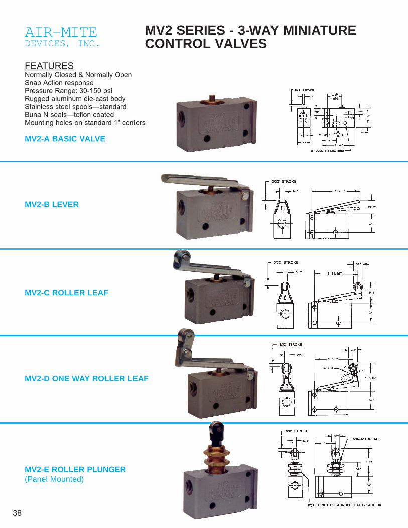
MV2 SERIES - 3-WAY MINIATURECONTROL VALVES
FEATURESNormally Closed & Normally OpenSnap Action responsePressure Range: 30-150 psiRugged aluminum die-cast bodyStainless steel spools—standardBuna N seals—teflon coatedMounting holes on standard 1" centers
MV2-A BASIC VALVE
MV2-C ROLLER LEAF
MV2-B LEVER
MV2-D ONE WAY ROLLER LEAF
MV2-E ROLLER PLUNGER(Panel Mounted)
39
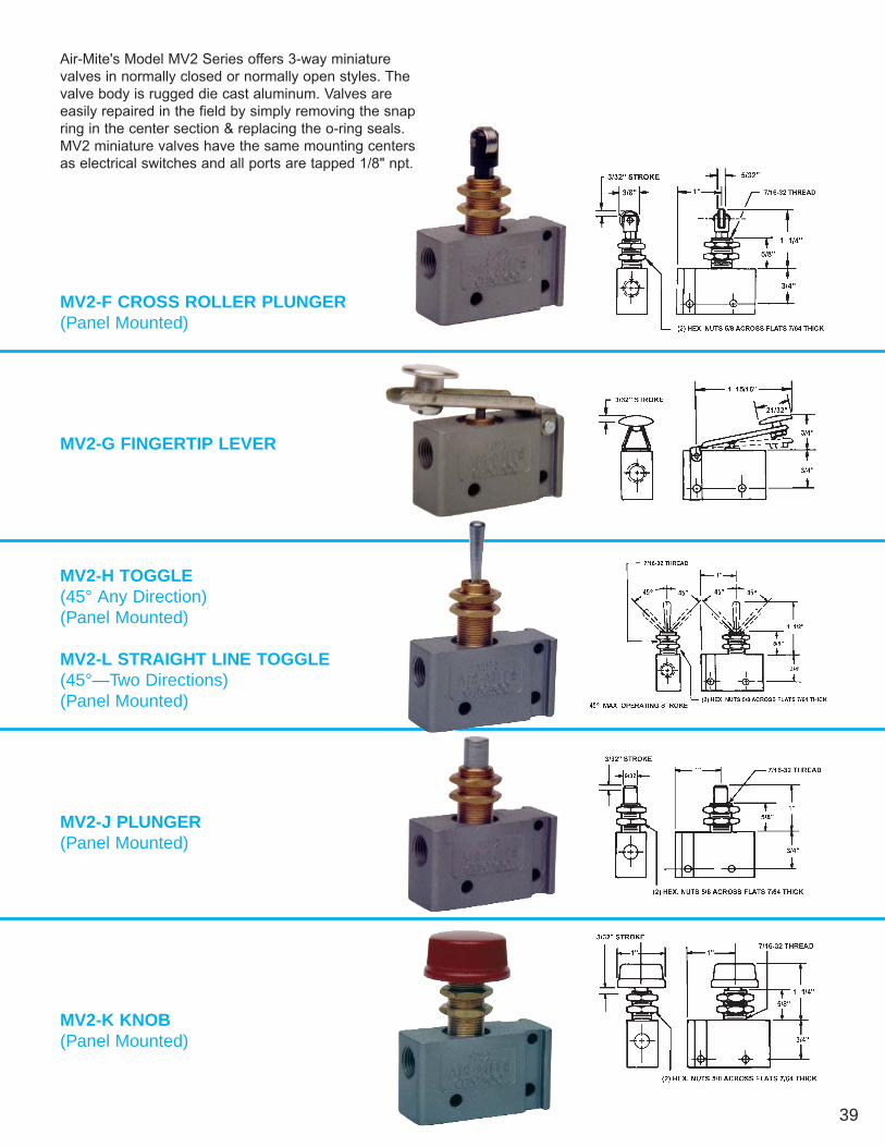
MV2-F CROSS ROLLER PLUNGER(Panel Mounted)
MV2-H TOGGLE(45° Any Direction)(Panel Mounted)
MV2-L STRAIGHT LINE TOGGLE(45°—Two Directions)(Panel Mounted)
MV2-G FINGERTIP LEVER
MV2-J PLUNGER(Panel Mounted)
MV2-K KNOB(Panel Mounted)
Air-Mite's Model MV2 Series offers 3-way miniaturevalves in normally closed or normally open styles. Thevalve body is rugged die cast aluminum. Valves are easily repaired in the field by simply removing the snapring in the center section & replacing the o-ring seals.MV2 miniature valves have the same mounting centersas electrical switches and all ports are tapped 1/8" npt.

40
AIR-MITEDEVICES, INC.
AIR-MITEDEVICES, INC.
MV3 & MV3-P SERIES - MINIATUREVALVE - POPPET DESIGN
3 WAY VALVESFEATURES 3-way normally closed with 1/8" npt ports High flow POPPET design Anodized aluminum body Valve Insert Screw-in cartridge assy. for easy mount-ing, repair & maintenance
Large palm button model MV3-P assures easy actu-ation
RMV3 & RMV3-P repair kits assure easy repair or replacement
MV3P - PALM BUTTON
SLIDE VALVES
QUICK EXHAUST VALVES
The Slide Valve is a manually operated, two-position,three-way valve for pneumatic applications. Permitsinstant gauge reading, with gauge vented to atmos-phere with valve sleeve in other position. Aluminumsleeve assures ease of control and positive action.Provides a positive shutdown when modifying or per-forming maintenance to air press circuitry.
Fast air dumping action permits use of smallervalves and piping
Increases system efficiency & speeds
Quick Exhaust Valve design gives instantaneous andcomplete venting of the exhaust air of cylinders, air
Maximum Operating Pressure: 250PSIMaterial: Body-Steel (Black Oxide)
Sleeve AluminumRetaining Ring-SteelO-Ring - Buna N
Temperature Range: -40°F to +212°F (O-Ring)
VALVE NO. SIZE A B C
SV125 1/8 2 1/2 7/8 DIA. .98
SV250 1/4 2 3/4 1 1/8 DIA. 1.53
SV375 3/8 2 13/16 1 1/8 DIA. 1.78
SV500 1/2 3 3/4 1 1/2 DIA. 3.26
MODEL INLET INLET CYLINDEREXHAUST EXHAUSTNUMBER P O RT C V P O RT P O RT C V
QV125 1/8 .50 1/4 1/4 1.0
QV250 1/4 1.3 1/4 3/8 1.4
QV375 3/8 2.31 3/8 3/8 2.86
QV500 1/2 3.48 1/2 3/4 5.45
DIMENSIONS
DIMENSIONS
Operating Pressure: Min. 20 PSI; Max. 125 PSI.Maximum ³P to shift diaphragm is 5-8 PSI. † 5 psi
QV250QV375
QV500 QV125
SLIDE VALVES • QUICK EXHAUSTVALVES

41
AIR-MITEDEVICES, INC.
FLOW CONTROL - NEEDLE - CHECKVALVES
SPECIFICATIONS:Minimum Operating Pressure: all models 5 psiMaximum Operating Pressure: All models 2000 psiViton O-Ring seals standardHousing, Plug, Body Brass Hexagon
Needle BrassTamperproof key Cadmium plated steelBall & Retainer Stainless steelPoppet Brass with Viton O-ring
FLOW CONTROLVALVECombines an adjustable nee-dle valve for flow control in onedirection, with a ball checkwhich opens for full flow in theopposite direction. It’s compactstem has wrench flats foradjusting flow setting.
NEEDLE VALVEExtremely efficient flow restric-tor featuring compact design,fast stem adjustment, anddurable stem packing.
CHECK VALVE
FLOW VALVE
CHECK VALVE
Advanced piston type designpermits mounting horizontally orvertically without affecting opera-tion. Soft-seat piston operates on slightdifferential pressure, closes to bubble tight sealto assure zero leakage. Stainless steel pistonand light helical spring operate smoothly. Valve isavailable with special springs for alternate breakpressures. (Contact factory)
EASY READ—FLOW-NEEDLE-CHECK VALVES With Numerical Readout
FEATURES: Specifications see above top of page Metal Setting knob & stem Positive position setting for precise flow control & readout Accurate adjustment to within fraction of a turn
Flow control & Needle valves: Provide controlled flow in onedirection, free flow in opposite direction. Flow adjustment canbe made under pressure. Knob setting can be locked in anydesired position.
Check Valves operate on slight differential pressure. Full flowis permitted in the direction of the arrow, positive check in the
P D L E G CvVALVE NO. PIPE SIZE HEX.
F-125 1/8 .687 1.750 1/2 9/32 .23
F-250 1/4 .875 2.375 5/8 5/16 .54
F-375 3/8 1.062 2.750 3/4 11/32 .83
F-500 1/2 1.312 3.187 1 3/8 1.47
F-750 3/4 1.625 3.562 1 1/8 15/32 1.90
P D L E CvVALVE NO. PIPE SIZE HEX.
N-125 1/8 .687 1.5 1/2 .20
N-250 1/4 .875 2.0 5/8 .43
N-375 3/8 1.062 2.250 3/4 ,78
N-500 1/2 1.312 2.656 1 1.24
N-750 3/4 1.625 2.937 1 5/8 1.93
P D L E CvVALVE NO. PIPE SIZE HEX.
PC-125 1/8 .687 1.5 9/32 .23
PC-250 1/4 .875 2.0 5/16 .54
PC-375 3/8 1.062 2.25 11/32 .83
PC-500 1/2 1.312 2.656 3/8 1.47
PC-750 3/4 1.625 3.00 15/32 1.90
SIZE A OPEN A CLOSED B SQUARE C D E HEX F
1/8 1 5/8 1 15/32 5/8 1 15/16 1 7/16 - 1 11/16
1/4 1 31/32 1 3/4 3/4 2 13/32 1 3/4 - 2
3/8 2 1/4 2 1 2 7/8 2 1/16 - 2 1/2
1/2 2 13/16 2 15/32 1 1/8 3 7/16 2 1/2 - 2 15/16
3/4 3 3/16 2 13/16 1 3/8 3 3/4 2 3/4 - 3 1/4
1 6 1/8 5 3/4 - 4 1/2 4 1/2 1 3/4 4 1/2 EPC Series
EN Series
EF Series
42
AIR-MITEDEVICES, INC.
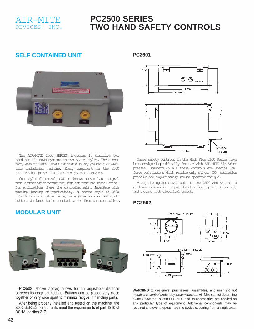
PC2500 SERIES TWO HAND SAFETY CONTROLS
SELF CONTAINED UNIT
The AIR-MITE 2500 SERIES includes 10 positive twohand non tie-down systems in two basic styles. These com-pact, easy to install units fit virtually any pneumatic or elec-tric industrial machine. Every component in the 2500SERIES has proven reliable over years of service.
One style of control station (shown above) has integralpush buttons which permit the simplest possible installation.For applications where the controller might interfere withmachine loading or productivity, a second style of 2500SERIES control (shown below) is supplied as a kit with palmbuttons designed to be mounted remote from the controller.
WARNING to designers, purchasers, assembles, and user. Do notmodify this control under any circumstances. Air-Mite cannot determineexactly how the PC2500 SERIES and its accessories are applied onany particular type of equipment. Additional components may berequired to prevent repeat machine cycles occurring from a single actu-
These safety controls in the High Flow 2600 Series havebeen designed specifically for use with AIR-MITE Air Arborpresses. Standard on all these controls are special low-force push buttons which require only a 2 oz. (55) activationpressure and significantly reduce operator fatigue.
Among the options available in the 2500 SERIES are: 3or 4 way continuous output: hand or foot operated systems;and systems with electrical output.
PC2502
PC2502 (shown above) allows for an adjustable distancebetween its deep set buttons. Buttons can be placed very closetogether or very wide apart to minimize fatigue in handling parts.
After being properly installed and tested on the machine, the2500 SERIES control units meet the requirements of part 1910 ofOSHA, section 217.
MODULAR UNIT
PC2601

43Please see pages 42-44 in this catalog for full information on anti tie-down controls.
FEATURES• 3-way Output–std 4-way–available
• Low Fatigue–deep set buttons require only 2 oz. activation force
• True non-tie down–buttons must be depressed within .4 seconds
• Rugged construction–Hoffman steel box standard
• Safe - Units meet the requirements of OSHA 1910 Sec 217 with proper installation
• Customized for use with Air-Mite components–either pneumatic or electrical output
Supply Pressure: 80 PSI
Operating Temperature: 35°F - 125°F
Operating Force: 2 oz each button
Button Diameter: 2"
Pneumatic Connections:1/8" NPT — PC25021/4" NPT — PC2601
Electrical Output: 15 AMP. 115 or 250 VAC SPDT
Lubrication: None (Dry air only)
Filtration: 5 Micron
Pneumatic Output*:
8 CFM @ 70 PSI20 CFM @ 70 PSI – avail
Electrical Connections:6" leads through 1/2" conduit connections
PIPING LAYOUTS FOR 2500 SERIES CONTROLS3 WAY PNEUMATIC OUTPUT
Systems will provide a sustained 3 way pneumatic outputwhen both palm buttons are depressed. Units are ideal foroperating small spring returned or double-acting air cylin-
ders by piloting remote air or hydraulic valves as shownbelow. Please refer to the specifications above.
MODEL PC2601 SHOWN
MODEL PC2502 SHOWN
LOGIC MODULE
(5 Micron)
(5 Micron)

44
AIR-MITEDEVICES, INC.
SC3000 SERIES TWO HAND SAFETYCONTROLS—STAND ALONE MODELS
3-Way Output–standardOAL–13-1/4"-std 9-1/2"-availSupply Pressure: 60-100 psiFiltration: 5 Micron
Connections: 5/32" instant fittingsLubrication: None allowedOperating Force: 5 oz. (each button)Button Diameter: 1-3/8"
FEATURES• Safe–Meets requirements of OSHA 1910 Sec 217
• Quick & Easy Installation
• Retrofit Air-Mite presses–specifically designed to simply retrofit with existing presses in the fieldor to work with any type of new equipment
The SC3000 Series represents the newest addition to Air-Mite two hand safetycontrols. The SC3000 provides versatility—with stand alone and press readymodels—and economy in a compact package.
Model SC3000
End View SC3000 - Top View
SC3000 - Rear View
Model SC3400(Includes Reset Button)Other Models:
SC4000 includes SC3400 & logic for clamp circuit + MV2 limit valveSC4500 includes SC3400 & 1-30 sec timer for sequential timing circuits
WARNING: ALL AIR-MITE CONTROLS ARE DESIGNED TO OPERATEPNEUMATIC VALVES AND CYLINDERS. THEY ARE NOT TO BE USEDWITH FLYWHEEL PRESSES, BRAKE PRESSES OR SIMILAR DEVICES. ITIS THE BUYERS RESPONSIBILITY TO DETERMINE THE USE ANDMOUNTING LOCATION OF THIS DEVICE. THIS EQUIPMENT PERFORMSTHE FUNCTION OF A TWO HAND NO TIE DOWN CONTROL ONLY. ALLOTHER PRESCRIBED SAFETY DEVICES, INCLUDING GUARDING, MUSTBE USED WITH THIS EQUIPMENT. IT IS THE BUYERS RESPONSIBILITYTO DETERMINE THE PROPER APPLICATION, LOCATION AND USE OFTHIS EQUIPMENT.
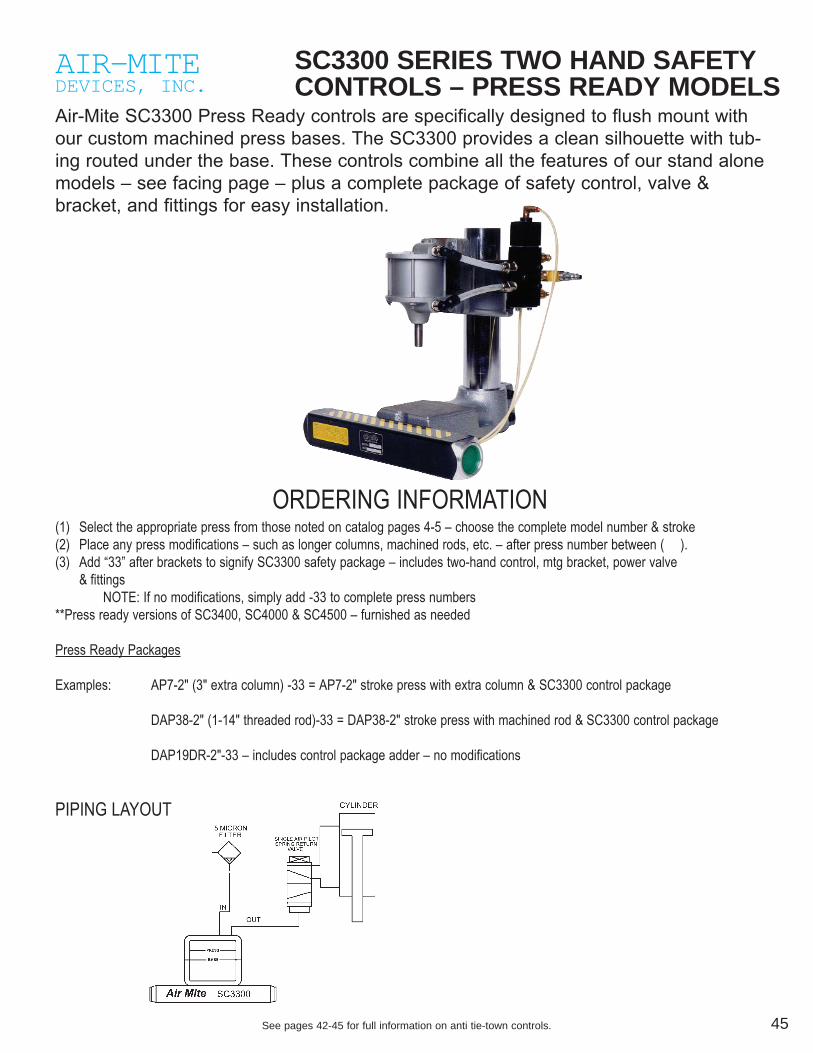
45See pages 42-45 for full information on anti tie-town controls.
AIR-MITEDEVICES, INC.
SC3300 SERIES TWO HAND SAFETYCONTROLS – PRESS READY MODELS
Air-Mite SC3300 Press Ready controls are specifically designed to flush mount withour custom machined press bases. The SC3300 provides a clean silhouette with tub-ing routed under the base. These controls combine all the features of our stand alonemodels – see facing page – plus a complete package of safety control, valve &bracket, and fittings for easy installation.
ORDERING INFORMATION(1) Select the appropriate press from those noted on catalog pages 4-5 – choose the complete model number & stroke(2) Place any press modifications – such as longer columns, machined rods, etc. – after press number between (AA).(3) Add “33” after brackets to signify SC3300 safety package – includes two-hand control, mtg bracket, power valve
& fittingsNOTE: If no modifications, simply add -33 to complete press numbers
**Press ready versions of SC3400, SC4000 & SC4500 – furnished as needed
Press Ready Packages
Examples: AP7-2" (3" extra column) -33 = AP7-2" stroke press with extra column & SC3300 control package
DAP38-2" (1-14" threaded rod)-33 = DAP38-2" stroke press with machined rod & SC3300 control package
DAP19DR-2"-33 – includes control package adder – no modifications
PIPING LAYOUT

46 Please see pages 42-45 in this catalog for full information on anti tie-down controls.
AIR-MITEDEVICES, INC.AIR-MITEDEVICES, INC.AIR-MITEDEVICES, INC.
SAFETY LOCK OUT VALVES—LV3 SERIESModels LV3101 1/8", LV3201 1/4", LV3301 3/8",LV3401 1/2", LV3601 3/4"
AIR-MITEDEVICES, INC.
LOCKOUT SLIDE VALVES 2-WAY & 3-WAY
Satisfies OSHA Standard 29 CFR 1910-Control Hazardous EnergySources.
Protects employees performing service, maintenance or repairs of equip-ment powered by pneumatic, hydraulic or electrical energy.
• Suitable for applications up to 150 psi air, 300 psi hydraulic• Entry from right or left side• Exhaust inlet same size for faster shutdown• Supplied with lock & key—specify keyed alike or keyed different
Valve will be locked in Normally Closedposition to prevent accidental operation.
FEATURES• Anodized aluminum body• Electroless nickel spools• Teflon coated Buna N O-rings—Viton optional
Satisfies OSHA Standard 29 CFR 1910-Control Hazardous Energy Sources.
FEATURES• Nickel plated housing ideal for medical, chemical & food• Lock in OFF-EXHAUST position only (OSHA requirement)• Slide of high impact plastic—safety yellow for quick identification• Slide cannot be removed when valve is locked (OSHA requirement)• High air flow—minimal pressure drop• Controlled exhaust rate muffles noise and prevents rupture of precise filter
elements due to high back flow
Protects employees performing service, maintenance or repairs to equipmentpowered by pneumatic, hydraulic or electrical energy. OSHA regulationrequires machines and equipment to be locked out from the energy sourcewhen service or maintenance is performed.
V102Valve is locked in closed position in photo.
PORTS MODEL DIMENSIONS
NPTF NUMBER AVG. CV. A B C W T. OZ.
2-way 3-way inches
1/4" V102 V202 2.7 1.7 3.1 1.92 6.5
3/8" V103 V203 6.4 1.7 3.1 1.92 6.5
1/2" V104 V204 6.4 1.7 3.1 1.92 6.5
Materials and Specifications:Body: Nickel plated zincSlide: Safety yellow, 15% Teflon,
high-impact plasticSeals: Pre-lubricated Buna O-RingsScrews: Nickel plated steelTemperature Range: 40-150° FPressure Range: 0-250 PSIGExhaust Bleed at 100 PSI: 7 SCFM
LV3101, LV3201 LV3301, LV3401, LV3601

47
AIR-MITEDEVICES, INC.AIR-MITEDEVICES, INC.
MINIATURIZED AIR COMPONENTS
AIR-MITEDEVICES, INC.
AIR VOLUME CHAMBERS
CYLINDERSAIR-MITE Miniaturized 3/8" bore, 1/2" stroke, spring return, single-acting air cylin-ders are machined from solid hexagon aluminum bar stock and have an anodizedfinish. The piston, ram and end cap are machined from cold rolled steel. Designof the cylinder permits quick, easy packing replacement if necessary.Simple, practical design of cylinder makes it readily adaptable for a wide varietyof uses. When desired, a number of cylinders can be ganged on the i-port mani-fold, or the cylinder may be screwed directly into the 3-way Valve designed espe-cially for these cylinders.MODEL No. MC1 1/8 PIPE THD.
MANIFOLDSThe Miniaturized 8-Port Manifold is machined from aluminum alloy bar stock andanodized. Air inlet and the 8 ports are 1/8-27 pipe thread. Two mounting holes are 5/32"diameter. Careful machining and accurately threaded openings assure fast, easy installa-tion. In applications requiring more than 8 outlets, manifolds may be coupled in tandemwith a coupling.This Manifold is designed for use in applications requiring multiple miniature cylinderactuations from a single source. Unusually large air passages also permit its use withlarge cylinders and components.
MODEL No. MM1 1/8 PIPE TAP - 9 HOLES
F25 MANIFOLDThe F25 is used in applications requiring up to 8outlets 1/4" taper pipe threads. Mounting holesare 3/16" diameter. The 8 side inlet ports and 2end ports are 1/4" npt.
MODEL No. F25 1/4 PIPE TAP - 10 HOLES
F25
Easy to connect, mount & use• Series BVC: All brass construction• Series AVC: All anodized aluminum construction• 10 Different sizes• Maximum Pressure—150 psi• Larger Capacities—available upon request
Air-Mite volume chambers are useful in many applicationsand are especially suited for use in time delay circuits andfor volume storage.Each volume chamber has threaded ports at each end foreasy installation. See chart at right for bore sizes, volumecapacities & dimensions of each different chamber.
AVC 125-1VOLUME
CHAMBER
BVC 100-3VOLUME
CHAMBER
AVC 125-3VOLUME
CHAMBER
BVC 100-5VOLUME
CHAMBER
BORE PA RT NO. VOLUME/CU. IN. A B C D
1.00 BVC100-1 .883 1 7/8 1.250 .625 1/8-27
1.00 BVC100-2 1.225 2 5/16 1.250 .625 1/8-27
1.00 BVC100-3 1.508 3 7/16 1.250 .625 1/8-27
1.00 BVC100-4 2.356 4 7/16 1.250 .625 1/8-27
1.00 BVC100-5 3.142 5 7/16 1.250 .625 1/8-27
1.00 BVC100-6 3.927 6 7/16 1.250 .625 1/8-27
1.00 BVC100-7 4.721 7 7/16 1.250 .625 1/8-27
1.250 AVC125-1 1.687 2 9/16 1.500 .625 1/8-27
1.250 AVC125-2 2.914 3 9/16 1.500 .625 1/8-27
1.250 AVC125-3 4.414 4 9/16 1.500 .625 1/8-27
MM1

48
AIR-MITEDEVICES, INC.
FILTERS—REGULATORS—OILERSALL FILTERS AND LUBRICATORS FURNISHED WITH SAFETY BOWL GUARD
MODULAR FILTER/REGULATOR/LUBRICATORNew modular filter, regulator, lubricator offerssimple & convenient assembly with advancedengineering benefits. The fog type lubricatorsends all metered air downline in fog dropletsaccommodating a wide line of applications.The modular filter delivers superior flow per-formance up to 100 SCFM. Individual unitscan be installed or removed on-line withoutdisturbing existing piping. Piping size neededis accomplished quickly by use of separate1/4", 3/8", and 1/2" insert pipe ports.
STANDARD FILTER/REGULATOR/LUBRICATORStandard filter, regulator, lubricator combina-tion units are designed to provide a clean, fil-tered flow of properly lubricated, preciselyregulated, pressurized air. All units areequipped with bowl guards as standardequipment. These units assure improved reli-ability of air circuits and extend service lifeand performance of all air powered tools and
MINIATURE FILTER/REGULATOR/LUBRICATORSeries 7681, small air regulators designed forapplications where space is a factor. Series7682 two-way regulator has extra low pres-sure side connection. Maximum supply pres-sure 200 PSI. Compact assemblies of Air-Mite Miniature Filters, Regulators andLubricators are especially suited for applica-tions where space or low flow requirement is
FILTER/REGULATOR COMBINATION (DUO)Combination unit incorporating the superiorflow performance of our standard filter withthe precise control capability of our compact,highly balanced regulator. Regulator containsdisc assembly which minimizes the effect ofsupply pressure variations. This combinationis ideally suited for high flow industrialrequirements, as well as those requiring pre-cise pressure control. Available in 1/4", 3/8",
INTEGRAL FILTER REGULATOR8600 SERIESThe Air-Mite Integral filter/regulatoracts as a dual stage system. Itsfirst stage is that of a filter to elimi-nate condensed moisture, pipescale, dirt and rust from the air line.Its second stage is that of a highperformance regulator. Finally, thisintegral unit features a triple stagebaffle, a cleanable, porous bronze40 micron element and a plastic
PIGGY-BACK MODELAll of the features of the mini regulator plusthe space saving convenience of an integralfilter and regulator combined in one unit. The20 micron, screw in, porous bronze filter ele-ment is cleanable, and can be drained bydepressing tire valve.
Max. pressure:150 psiTemp. rated:40°F to 120°FFlow Rates:Up to 100 SCFM
DIMENSIONS B O W L NET WT.MODEL NO. A B C CAPACITY POUNDS
C33352 11 1/2 3 3/4 5 7/16 5 oz. 4
C33353 11 1/2 3 3/4 5 7/16 5 oz. 4
C33354 11 1/2 3 3/4 5 7/16 5 oz. 4
DIMENSIONS B O W L NET WT.MODEL NO. A B B CAPACITY POUNDS
8672BGT 10 3/4 1 3/4 5 11/16 9 oz. 4.5
8673BGT 10 3/4 1 3/4 5 11/16 9 oz. 4.5
3564-8BG 11 1 3/4 5 11/16 9 oz. 5.5
MODULAR
STANDARD FILTER/REGULATOR/LUBRI-
DIMENSIONS B O W L NET WT.MODEL NO. A B B CAPACITY POUNDS
N70352 6 1 1/4 5 11/16 9 oz. 3.2
N70353 6 1 1/4 5 11/16 9 oz. 3.2
N70354 6 1 1/4 5 11/16 9 oz. 3.2
3506MS 9 1/8 1 1/2 8 3/8 29 oz. 8
FILTER-REGULATO R
MODEL NO. Plastic Bowl & Bowl Guard INLET/OUTLET
B752 1/4 NPT
B753 3/8 NPT
B754 1/2 NPT
INTEGRAL FILTER/REGULATO R
PIPE DIMENSIONS B O W L NET WT.MODEL NO. SIZE A B C CAPACITY POUNDS
7681 1/8 5 1/4 2 1/4 3 1 oz. 1.3
7682 1/4 5 1/4 2 1/4 3 1 oz. 1.3
MINIATURE CONTROLSFilter-Regulator w/Gauge-Lubricator
All Filters, Regulators or Lubricators are available as single units in both stan-dard and miniature sizes. Please consult factory for details.
*Add .1 lb for gauge
MODEL PIPE SIZE NET. WT. POUNDS*
B741 1/8 .5
B742 1/4 .5
PIGGY-BACK MODEL
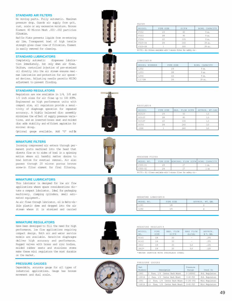
49
STANDARD LUBRICATORSCompletely automatic dispenses lubrica-tion immediately, but only when air flows.Uniform, controlled injection of pre-atomizedoil directly into the air stream ensures maxi-mum lubrication and protection for air operat-ed devices. Adjusting needle permits MICROadjustment to prevent flooding.
STANDARD REGULATORSRegulators are now available in 1/4, 3/8 and1/2 inch sizes for air flows up to 100 SCFM.Engineered as high performance units withcompact size, all regulators provide a sensi-tivity of diaphragm operation for repeatedaccuracy. A highly balanced disc assemblyminimizes the effect of supply pressure varia-tions, and an inserted brass seat and moldeddisc adds stability and efficient aspiration forminimal droop.
Optional gauge available. Add "G" suffix
MINIATURE FILTERSIncoming compressed air enters through per-manent ports machined into the head thatdirects flow on to sides of bowl in a spinningmotion where all harmful matter drains tobowl bottom for eventual removal. Air alsopasses through 20 micron porous bronzescrew-in filter element for final filtering.
MINIATURE LUBRICATORSThis lubricator is designed for low air flowapplications where space considerations dic-tate a compact lubricator. Ideal for packagingmachinery, clamping cylinders, small auto-mated equipment.
As air flows through lubricator, oil is fed to vis-ible plastic dome and dropped into the airstream where it is atomized and carried
MINIATURE REGULATORSHave been developed to fill the need for highperformance, low flow applications requiringcompact design. Both air and water servicemodels are available. Sensitive diaphragmsdeliver high accuracy and performance.Rugged valves with brass and zinc bodies,molded rubber seats and stainless stemsmake these mini regulators the most durableon the market.
PRESSURE GAUGESDependable, accurate gauge for all types ofindustrial applications. Gauge has bronzemovement and dual scale.
STANDARD AIR FILTERSNo moving parts. Fully automatic. Maximumpressure drop. Guards air supply from grit,rust, scale or any excessive moisture. BronzeElement 40 Micron Mesh .001-.002 particlesFiltration.
Baffle Plate prevents liquids from re-enteringair line. Transparent bowl of high tensilestrength gives clear view of filtration. Elementis easily removed for cleaning.
MODEL PIPE SIZE SCFM BOWL CAPACITY
F352 1/4 60 9 oz.
F353 3/8 90 9 oz.
F354 1/2 105 9 oz.
F329-06 3/4 260 29 oz.
F329-08 1 300 29 oz.
FILTER
MODEL NUMBER PIPE SIZE BOWL CAPACITY
L352 1/4 9 oz.
L353 3/8 9 oz.
L354 1/2 9 oz.
L376W 3/4 29 oz.
LUBRICATO R
MODEL PIPE SIZE MAX. FLOW SCFM APPROX. WT-LBS
R352T 1/4 50 1.5
R353T 3/8 80 1.5
R354T 1/2 100 1.5
R356 3/4 240 3.0
1588 1 240 3.0
REGULATO R
MODEL NO. PIPE SIZE NOMINAL FLOW SCFM BOWL CAPACITY
F300-01 1/8 27 1 oz.
F300-02 1/4 27 1 oz
MINIATURE FILTER
MODEL NO. PIPE SIZE APPROX. WT. LBS.
L181 1/8 .5
L182 1/4 .5
MINIATURE LUBRICATO R
MODEL PIPE MAX. FLOW MAX FLOW APPROX.NO. SIZE SCFM (G.P.M.) W T. LBS.
R161 1/8 20 - .375
R162 1/4 20 - .375
2612 1/4 20 5.0 .125
2613* 1/4 20 5.0 .125
MINIATURE REGULATO R
*WATER SERVICE WITH STAINLESS STEEL
NOTE: All filters available with 5 micron filter for safety cir-
NOTE: All filters available with 5 micron filter for safety cir-
Part PressureNumber Description Range Used On
1481 2 Face, 1/4 Center Back Mount 0-160PSI Std. Regulators
1481A 2 face, 1/4 Center Back Mount 0-60 PSI Std. Regulators
1681 1 1/2 Face, 1/8 Center Back Mount 0-160 PSI Mini Regulators
1681A 1 1/2 Face, 1/8 Center Back Mount 0-60 PSI Mini Regulators
PRESSURE GAUGES

50
AIR-MITEDEVICES, INC.
VACUUM PUMPS
Model #33 SINGLE VENTURIAir-Mite Model 33 single-venturi vacuum pump uses standard compressed air to
develop a vacuum flow through the pump. The small size and light weight of thismodel ensures good response time and low operating cost. As with our line of multi-ple-venturi pumps, the Model 33 pump can be used with packaging machinery, lab-oratory equipment, dental equipment, printing machinery, textile machinery, and tankevacuation as well as scores of other applications in various industries.
The multi-venturi vacuum pump is ideal for explosion-proof applications and a widerange of other applications in robotics, automated machinery, control of equipment inthe packaging, printing, dairy, and commercial candy-making industries, as well asfor mail inserting and glass handling equipment and for medical, dental, and researchlaboratories.
When compressed air is forcedthrough a conical nozzle, its velocityincreases and a decrease in pres-sure occurs. This principle, discov-ered by 189th century physicist G.B.Venturi, can be used to generate vac-uum economically without a singlemoving part.
Multi Venturi DesignAIR-MITE’S PowerVac design of vacu-um generators incorporates a series ofVenturi nozzles. Each nozzle has aprogressively larger orifice selected to
extract the maximum amount of ener-gy from the compressed air while opti-mizing the levels of vacuum generat-ed. Normally, no special prefilters arerequired because the Venturi nozzlesare aligned to allow “straight through”air flow. Thus, any air line contami-nants easily clear the generator with-out clogging or building up.
n Compressed Air Driven PowerVac Pumps are easy to install.They operate efficiently on shop air(20 to 90 PSI) and are well suited toexplosion-proof applications. Andthere’s no RF noise generated toaffect electrical/electronic systemseither.
n Economical to OperateThe innovative PowerVac multi-Venturidesign uses less compressed air, yetdelivers three to four times more vacu-um flow than single Venturi units.
n Compact SizeAllows pump placement closer to thepoint of use. Shorter air lines cost lessand quicken response.
n Light Weight ConstructionMost models weight less than twopounds providing maximum flexibilityand mounting ease.
n Superior ControlVacuum levels are controlled byadjusting inlet pressure. Pumps canbe cycled on & off by controlling inletpressure rather than the vacuum line.Thus, there’s no wasted energy.
n No moving partsExpect extra long pump life with nolubrication required.
n Quiet OperationPumps come equipped with exhaustsilencers, resulting in low noise levelsin the 60-65 dB range.
n Low CostPricing that’s well below foreignimports is only part of the picture.Combined with ease of installation, itmeans that your total investment is farless when you use AIR-MITE’sPowerVac.
n All Metal ConstructionViton valves standard.
n Quick Change ValvesValves can be replaced using only ascrew driver and without removing thepump from its mounting.
Ten Important Design Features:
AIR-MITE POWERVACMULTIPLE-VENTURI VACUUM PUMPSEfficient, Reliable Straight-Thru Design
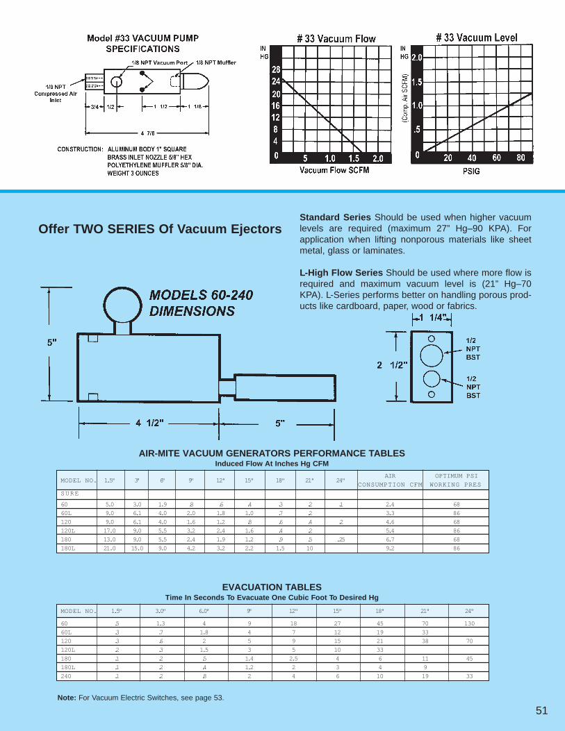
51
Offer TWO SERIES Of Vacuum EjectorsStandard Series Should be used when higher vacuumlevels are required (maximum 27” Hg–90 KPA). Forapplication when lifting nonporous materials like sheetmetal, glass or laminates.
L-High Flow Series Should be used where more flow isrequired and maximum vacuum level is (21” Hg–70KPA). L-Series performs better on handling porous prod-ucts like cardboard, paper, wood or fabrics.
AIR-MITE VACUUM GENERATORS PERFORMANCE TABLESInduced Flow At Inches Hg CFM
MODEL NO. 1.5" 3" 6" 9" 12" 15" 18" 21" 24"AIR OPTIMUM PSI
CONSUMPTION CFM WORKING PRES
SURE
60 5.0 3.0 1.9 .8 .6 .4 .3 .2 .1 2.4 68
60L 9.0 6.1 4.0 2.0 1.8 1.0 .7 .2 3.3 86
120 9.0 6.1 4.0 1.6 1.2 .8 .6 .4 .2 4.6 68
120L 17.0 9.0 5.5 3.2 2.4 1.6 .4 .2 5.4 86
180 13.0 9.0 5.5 2.4 1.9 1.2 .9 .5 .25 6.7 68
180L 21.0 15.0 9.0 4.2 3.2 2.2 1.5 10 9.2 86
EVACUATION TABLESTime In Seconds To Evacuate One Cubic Foot To Desired Hg
MODEL NO. 1.5" 3.0" 6.0" 9" 12" 15" 18" 21" 24"
60 .5 1.3 4 9 18 27 45 70 130
60L .3 .7 1.8 4 7 12 19 33
120 .3 .6 2 5 9 15 21 38 70
120L .2 .3 1.5 3 5 10 33
180 .1 .2 .5 1.4 2.5 4 6 11 45
180L .1 .2 .4 1.2 2 3 4 9
240 .1 .2 .8 2 4 6 10 19 33
Note: For Vacuum Electric Switches, see page 53.
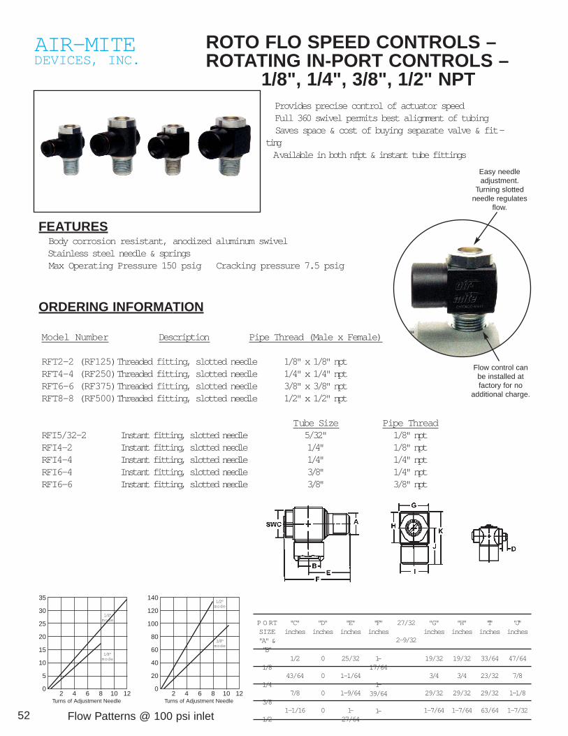
52
AIR-MITEDEVICES, INC.
ROTO FLO SPEED CONTROLS –ROTATING IN-PORT CONTROLS –
1/8", 1/4", 3/8", 1/2" NPT
FEATURES Body corrosion resistant, anodized aluminum swivel Stainless steel needle & springs Max Operating Pressure 150 psig Cracking pressure 7.5 psig
ORDERING INFORMATION
Model Number Description Pipe Thread (Male x Female)
RFT2-2 (RF125)Threaded fitting, slotted needle 1/8" x 1/8" nptRFT4-4 (RF250)Threaded fitting, slotted needle 1/4" x 1/4" nptRFT6-6 (RF375)Threaded fitting, slotted needle 3/8" x 3/8" nptRFT8-8 (RF500)Threaded fitting, slotted needle 1/2" x 1/2" npt
Tube Size Pipe ThreadRFI5/32-2 Instant fitting, slotted needle 5/32" 1/8" nptRFI4-2 Instant fitting, slotted needle 1/4" 1/8" nptRFI4-4 Instant fitting, slotted needle 1/4" 1/4" nptRFI6-4 Instant fitting, slotted needle 3/8" 1/4" nptRFI6-6 Instant fitting, slotted needle 3/8" 3/8" npt
Provides precise control of actuator speed Full 360 swivel permits best alignment of tubing Saves space & cost of buying separate valve & fit-ting Available in both nfpt & instant tube fittings
Flow Patterns @ 100 psi inlet
Easy needleadjustment.
Turning slottedneedle regulates
flow.
Flow control canbe installed atfactory for no
additional charge.
35
30
25
20
15
10
5
02 4 6 8 10 12
Turns of Adjustment Needle
140
120
100
80
60
40
20
02 4 6 8 10 12
Turns of Adjustment Needle
1/4"mode
1/8"mode
1/2"mode
3/8"mode
P O RTSIZE"A" &"B"
1/8
1/4
3/8
1/2
"C"inches
1/2
43/64
7/8
1-1/16
"D"inches
0
0
0
0
"E"inches
25/32
1-1/64
1-9/64
1-27/64
"F"inches
1-17/64
1-39/64
1-
27/32
2-9/32
"G"inches
19/32
3/4
29/32
1-7/64
"H"inches
19/32
3/4
29/32
1-7/64
"I"inches
33/64
23/32
29/32
63/64
"J"inches
47/64
7/8
1-1/8
1-7/32

53
AIR-MITEDEVICES, INC.
AIR LINE MUFFLERS
AIR-MITE Exhaust Silencers and Dust FiltersEffectively silences air in atmosphere and prohibits dustand/or dust particles from entering valves. Low silhouette ofthe unit makes it suitable for various types of mounting.
F201MUFFLER ISEASILYTHREADED ONSLEEVE OFVALVE.
MODELF2011/2-20 FTP
The Speed Control Silencer, a combination Exhaust Silencer andDust Filter, have a simple needle adjustment for regulating speedand air control. Simple construction and non-corrosive brass andbronze materials are used to provide durable simple, easy tomaintain and clean unit. Units are easily cleaned with cleaningsolvent or agent such as gasoline, or carbon tetrachloride, etc.
SCS 1/8" NPT SCS 3/8" NPT SCS 3/4" NPTSCS 1/4" NPT SCS 1/2" NPT SCS 1" NPT
Fits most valves. Two piece construction of non-corrosive brassand bronze materials. Easily cleaned in cleaning solvent or agent,such as gasoline, carbon tetrachloride, or by simply reversingpiece and blowing air thru it.
X201 1/8" NPT X201 3/8" NPT X201 3/4" NPTX201 1/4" NPT X201 1/2" NPT X201 1" NPT
U.S. Pat. No. 3,163,256
AIR-MITEDEVICES, INC.
VACUUM ELECTRIC SWITCHES
• LOW COST • EXCELLENT REPEATABILITY • SNAP ACTION • FAST RESPONSE
F-4000-XSeries
with cover w/o cover
F-4200-X Series
Panel Mount
Subminiature SizeLow Differential
The F-4000-X Series Standard Vacuum/ElectricSwitches interface from vacuum to electrical sys-tems. Ideal for precise vacuum sensing. The F-4000-X has adjustments for controlling the ON andOFF operating points. The switch is adjustable 4.0to 15" Hg.The F-4200-X Series Vacuum/Electric Switches
interface from vacuum to electrical control circuits.Ideal for low differential vacuum applications. Theswitch is adjustable from 0-29.9" Hg. Standard 1/8"
The switches have three electrical terminals:Normally Open, Normally Closed and Common. 15-amp switches are standard.
SPECIFICATIONSELECTRICAL
Switch Action: Single pole, double throwElectrical Rating: 15 amp, 125 or 250 volts ACElectric Switch: UL ApprovedElectrical Connections: .187" quick-connect terminal
MECHANICALOperating Speed: 25 millisecondsSignal Pressure: 30" Hg. max.
Temperature Limits: 40° to 120°F (4° to 49°C)MATERIALS
Housing: PolysulfoneDiaphragm: PolyurethaneSpring: Stainless Steel
MOUNTINGF-4000-X Series Flush mount—mounting hole.125" diameter, use No. 6 screw.F-4200-X Series Panel mount—mounting hole size 7/16" diameter..
PORT CONNECTIONSF-4000-X Series - 10-32 threads furnished with 10-32 x 1/16" I.D. barbed fitting.F-4200-X Series - 10-32 threads x 1/16" or 1/8" I.D. barbed fitting
ADJUSTMENT RANGEF-4000-X Series 4.0 to 15" Hg. Max.F-4200-X Series 0 to 29.9" Hg. MaxSpecial Operating Ranges on Request.
Note: For Vacuum Pump information, see pages 50-51.

54
AIR-MITEDEVICES, INC.
AIR HOLDING FIXTURES• Versatile • Fast Acting • Provides Secure Grip
can be used with Brown and Sharpe type collets
VERSATILE – Unique design permits using unit upright or posi-tioned on its side with same maximum efficiency.
• 3 Model Sizes—1/16" thru 1-1/4" capacities
Air-Mite air holding fixture provides compound lever-age and holding power to assure secure grip on partregardless of shape.
Force is applied evenly over the entire surface of thecollet. Smooth round objects as well as variousshaped work pieces are held firmly and securely dur-ing machining or assembling operation without the riskof causing scratches or distortion.
The air-holding fixture will accommodate any shape towhich a collet will conform. The device also serves asan accurate positioner, precisely maintaining thedesired location as succeeding work pieces areloaded and requiring negligible operator dexterity.
Chip blower (A) maintains intermittent outward flow,preventing chips or particles from entering and foulingthe collet’s expanding slots. Flow of liquid also servesto effectively cool the machining area. A mechanicalspring ejector for parts is available as an option ifdesired. See picture below.
Air-Mite 00-10 Air Holding Device issmall, compact, especially suited for usewith small milling machines or whereverlimited clearance exists between the bedand the spindle of the machine. Can beused with Brown & Sharpe type colletswith a capacity from 1/16” to 9/16” inrounds. Square: 3/16” to 13/32”.Hexagon: 3/16” to 1/2”.
Air-Mite 0-11 Air Holding Device is gen-erally recommended for use with workunder 1”. Used with Brown & Sharpetype collets No. 11 with a capacity from1/16” to 7/8” in rounds. Square 3/16” to19/32”. Hexagon: 3/16” to 3/4”.
Air-Mite 2-22 Air Holding Device isdesigned for use with those jobs requir-ing extra holding pressure. Use withHardinge 2-22 collets or similar. CapacityRound to 1-1/4” – Square 7/8” andHexagon 1-1/16”.
The three Air-Mite Holding Devices avail-able each use a different collet and havevarying capacities. All models use thesame type of stationary collets that pre-vent depth and center variances of workbeing held.
DRILL BUSHING BAR (OPTIONAL)This drill bushing bar may be used with aslip renewable bushing for drilling, tap-ping or reaming, etc., and can also be uti-lized as a depth stop.
MV2-L MINIATURE VALVE STRAIGHTLINE TOGGLE (45° – Two Directions) –Optional Accessory – Shown at right.The AIR-MITE miniature three-way valveshown can be used in a normally closedor normally open position. Serves dualpurpose. It operates the collet fixture andprovides blast of air necessary to clearany chips resulting from drilling opera-tions, etc.
NOTE: V3200 ROTORAM® VALVE canalso be used to operate AIR-MITE air-holding fixture.
SPRING EJECTOR STOP ASSEMBLYUsing Brown & Sharpe type of stop collet,an effective means of mechanical ejec-tion can be incorporated by just screwingthe AIR-MITE Spring Ejector StopAssembly into the bottom of the stop col-let. This unit serves as a stop assemblyand can be easily adjusted to obtain thestroke necessary to eject the part.
Approx.Model A B C D E F G H J K L M W eights
00-10 2 3/16 2 11/16 3 3/4 3 5/8 2 3/8 4 1/2 9 3 3/4 1/2 1/2 1/2 2 1/4 9 lbs.
0-11 2 3/4 2 11/16 5 1/8 4 3/16 2 3/4 5 3/4 11 1/2 4 1/2 1/2 1/2 3 1/16 16 lbs.
2-22 3 1/2 3 1/2 6 1/8 4 9/16 3 5/16 6 1/8 13 1/2 5 1/8 1/2 1/2 1/2 3 3/4 28 lbs.
A

55
AIR-MITEDEVICES, INC.
INSTANT FITTINGS
PUSH-IN BRASS TUBE FITTINGSBrass push-in connectors reduce installation time up to 75% . . . justpush nylon or poly tubing into the connector for positive, no-leak seal-ing. To remove the tubing, hold back the connector release ring and pullthe tubing free.
PA RT TUBE CIRCLIPS FLOWNO. SIZE O.D. L I.D.* DIA. D
62PL-2 1/8 .39 1.22 .39 .078
62PL-4 1/4 .47 1.26 .47 .177
62PL-6 3/8 .67 1.61 .67 .295
UNION 62PL
PA RT TUBE C P FLOWNO. SIZE B HEX MAX. L DIA D
62PLBH-2 1/8 .43 5/8 .24 1.22 .078
62PLBH-4 1/4 .55 3/4 .24 1.26 .177
62PLBH-6 3/8 .71 7/8 .35 1.63 .295
BULKHEAD UNION 62PLBH
PA RT TUBE PIPE THREAD FLOWNO. SIZE (NPTF) L DIA. D
66PL-2-2 1/8 1/8 1.16 .078
66PL-4-2 1/4 1/8 1.22 .177
66PL-4-4 1/4 1/4 1.34 .177
66PL-6-4 3/8 1/4 1.50 .295
FEMALE CONNECTOR 66PL
PA RT TUBE THREAD PIPE C FLOWNO. SIZE (NPTF) HEX L M DIA. D
68PL-2-2 1/8 1/8 3/8 .81 .41 .078
68PL-4-2 1/4 1/8 1/2 .96 .57 .188
68PL-4-4 1/4 1/4 9/16 .94 .39 .188
68PL-6-2 3/8 1/8 11/16 1.22 .83 .187
MALE CONNECTOR 68PL*
*Unions can be used as bulkhead unions, it is only necessary to mounttwo
NOTE Also available with 5/32" tube x 1/8" npt.
NOTE Also available with 5/32" tube x 1/8" npt.
PA RT TUBE PIPE THREAD C FLOWNO. SIZE (NPTF) HEX L M DIA. D
68PL-2-10X32 1/8 10-32 3/8 .83 .69 .098
68PL-5/32-10X32 5/32 10-32 3/8 .87 .71 .098
68PL-4-10X32 1/4 10-32 1/2 .87 .73 .098
MALE CONNECTOR 68PL-2*
*All straight male connectors have an internal hex for the use of an AllenKey to allow the fitting to be mounted in any position. This also permitsclose porting not possible with a standard wrench.
PA RT NO. TUBE SIZE L FLOW DIA. D
164PL-2 1/8 .69 .078
164PL-4 1/4 .73 .177
164PL-6 3/8 .98 .295
164PL-8 1/2 1.16 .393
UNION TEE 164PL
PA RT NO. TUBE SIZE L FLOW DIA. D
165PL-2 1/8 .68 .078
165PL-4 1/4 .73 .177
165PL-6 3/8 .98 .295
165PL-8 1/2 1.16 .393
UNION ELBOW 165PL
PA RT TUBE PIPE THREAD C FLOWNO. SIZE (NPTF) HEX L M DIA.
169PL-2-2 1/8 1/8 7/16 .69 1.16 .078
169PL-4-2 1/4 1/8 7/16 .73 1.20 .177
169PL-4-4 1/4 1/4 9/16 .73 1.38 .177
196PL-4-6 1/4 3/8 3/4 .71 1.42 .177
169PL-6-2 3/8 1/8 5/8 .98 1.38 .197
196PL-6-4 3/8 1/4 5/8 .98 1.57 .295
196PL-8-4 1/2 1/4 3/4 1.16 1.73 .312
MALE ELBOW SWIVEL 90 169PL
PA RT TUBE PIPE THREAD FLOWNO. SIZE (NPTF) L N DIA.
169PLNS-2-2 1/8 1/8 .67 .87 .078
169PLNS-4-2 1/4 1/8 .73 .87 .177
169PLNS-4-4 1/4 1/4 .73 1.08 .177
169PLNS-6-4 3/8 1/4 .98 1.14 .295
169PLNS-8-6 1/2 3/8 1.10 1.29 .394
90MALE ELBOW SWIVEL 90 169PLNS
PA RT TUBE PIPE THREAD C FLOWNO. SIZE (NPTF) HEX L M DIA.
171PL-2-2 1/8 1/8 7/16 .69 1.16 .078
171PL-4-2 1/4 1/8 7/16 .73 1.2 .177
171PL-4-4 1/4 1/4 9/16 .73 1.38 .177
171PL-6-4 3/8 1/4 5/8 .98 1.57 .295
171PL-6-6 3/8 3/8 3/4 .98 1.59 .295
171PL-8-6 1/2 3/8 3/4 1.16 1.73 .393
MALE RUN TEE SWIVEL 171PL
PA RT TUBE PIPE THREAD C FLOWNO. SIZE (NPTF) HEX L M DIA.
172PL-2-2 1/8 1/8 7/16 .69 1.16 .078
172PL-4-2 1/4 1/8 7/16 .73 1.20 .177
172PL-4-4 1/4 1/4 9/16 .73 1.38 .177
172PL-6-4 3/8 1/4 5/8 .98 1.57 .295
172PL-6-6 3/8 3/8 3/4 .98 1.59 .295
MALE BRANCH TEE SWIVEL 172PL

AIR-MITEDEVICES, INC.
AIR-MITEDEVICES, INC.4739 W. Montrose Ave., Chicago IL 60641Phone: (773) 286-3393 Fax: (773) 286-4703 Printed in USA 122000
Cylinder Power Factor Line Pressure, Lbs.Diameter & Bore Area 50 60 70 80 90 100 110 120 130 140 150Inches Square Inches Lbs. Lbs. Lbs. Lbs. Lbs. Lbs. Lbs. Lbs. Lbs. Lbs. Lbs.3/8 0.110 5.5 6.6 7.7 8.8 9.9 11.0 12 13 14 15 16.51/2 0.190 9.5 11.5 13.3 15.5 17 19 21.9 22.8 25 26.6 28.53/4 0.440 22 26.5 30.8 35 40 44 485 53 57 61.7 661 0.785 39 46.5 54.9 62.8 70.6 78.5 86 94 102 109.9 117.71 1/8 .0994 50 59 70 80 89 99 109 119 129 139 1491 1/4 1.22 61 74 86 98 110 122 134 146 159 171 1831 1/2 1.76 88 106 123 141 158 176 194 211 229 246 2651 5/8 2.07 103.5 124 145 165.5 186 207 228 248 269 290 310.52 3.14 157 188 220 250 283 314 346 377 408 439 4702 1/4 3.98 199 229 278 318 358 398 438 477 517 557 5972 1/2 4.91 242 290 338 387 432 483 530 580 638 687 7243 7.07 353 424 494 565 635 707 777 847 918 988 10604 12.56 628 754 879 1005 1130 1256 1382 1507 1633 1758 18855 19.63 982 1178 1374 1571 1767 1963 2159 2356 2552 2745 2945
Rod Dia. Full Thread (NF) Reduced Thread FemaleThread
CC RR FF1/4" 1/4-28 1/8-27 6-325/16" 5/16-24 1/4-28 8-323/8" 3/8-24 5/16-24 10-321/2" 1/2-20 7/16-20 1/4-283/4" 3/4-16 1/2-20 3/8-24
1" 1-14 3/4-16 1/2-20
THEORETICAL POWER CONVERSION TABLE
* To obtain push pull force for 550 Series Tandem Cylinders double the figures noted above for the 5” bore. For the 580 Triplex Series, triple the figures noted.
**Identify appropriate rod diameter for requested cylinder. Add thecorresponding letter—CC, RR or FF—after model number toobtain desired thread style. Threads noted at left are suggestedas standard. In addition to those noted, we can furnish any otherthreads upon request.
NOTE: To order wrench flats on rod ends, simply add WF aftermodel number.
GUARANTEEAIR MITE CYLINDERS or VALVES are guaranteed againstdefective workmanship and material for a period of 60 days fromdate of purchase. In event of defect, a cylinder or valve returnedPREPAID will be replaced NO CHARGE, F.O.B. our factory. Noproducts can be returned for credit after 6 months.
SPECIAL SERVICE OFFERNatural wear as a result of constant and unlimited use of theAIR-MITE CYLINDER may give cause for parts replacement.
NOTE: No Air-Mite products may be returned without obtainingan authorized RGA number. Credit will only be issued for unusedor unmarked current standard catalog items.
Restocking charge 20% on all authorized returns.
AIR-MITE CYLINDERS are built to give the maximum inholding power. However, some uses require a regulatedand controlled pressure. This table is furnished to act asa quick reference in power control. By referring to the
diameter of the cylinder to be used in the left column ofthe table and reading across, the line pressure requiredto give exactly the desired amount of force may be read-ily calculated.