air mover system with reduced reverse air flow
TRANSCRIPT
(12) United States Patent US006217440B1
(10) Patent N0.: US 6,217,440 B1 Wessel et al. (45) Date of Patent: Apr. 17, 2001
(54) AIR MOVER SYSTEM WITH REDUCED 3,275,083 9/1966 Allin ............................. .. 170/160.13 REVERSE AIR FLOW 3,339,425 9/1967 Seiden .. 74/393
3,560,109 2/1971 Lewis ..... .. 416/169
(75) Inventors: Mark William Wessel, New Oxford; * glasfiietaL - - , , 0 ison .... ..
gArzzlgsgm Smlth’ Bryn Athyn’ both of 4,376,614 3/1983 Woodruff 416/32 4,567,965 2/1986 Woodruff . 188/68
. . , 4,642,029 2/1987 CedoZ . . . . . . . . .. 416/129
(73) Ass1gnee: Unlsys Corporation, Blue Bell, PA 4,648,007 * 3/1987 Gamer ~~~~~~ __ 454/184 X (Us) 5,035,575 7/1991 Nielsen 6161. ....... .. 416/9
_ _ _ _ _ 5,438,226 8/1995 Kuchta ...... .. 307/125
( * ) Notice: SubJect to any disclaimer, the term of this 5,470,197 11/1995 Cafare?i 415/90 patent is extended or adjusted under 35 5,562,418 10/1996 Agius ............................. .. 416/169 R U.S.C. 154(b) by 0 days. 5,795,270 * 8/1998 Woods et al. .
5,890,959 * 4/1999 Petit 61 al. ......................... .. 454/184
(21) Appl- NO? 09/ 182,273 * cited by examiner
(22) Filed? Oct- 29! 1998 Primary Examiner—Harold Joyce (51) Int C17 H05K 7/20 (74) Attorney, Agent, or Firm—Rocco L. Adornato; Mark (52) U516. .11111111111111111 """"""""""" "1174547184, 361/695 T & P449
(58) Field of Search ................................... .. 454/184, 338, (57) ABSTRACT 454/341; 361/695 _ . . . .
An arr mover system is provided having plural arr movers - eac mounte aon an air ow at . ac o t e arr movers (56) References Cited _ h d 1 g ' ? P h E h h '
includes means mounted for forward rotation to generate U-S~ PATENT DOCUMENTS forward air ?ow. Each of the air movers also includes means
2 143 372 1/1939 Frink for preventing reverse rotation of the air ?ow generating 277027100 2/1955 Montieth ............................ .. 188/110 means> thereby reducing reverse air ?ow 2,737,018 3/1956 Bain et al. .. 60/39.14 3,176,173 3/1965 Straub et al. ........................ .. 310/59 17 Claims, 12 Drawing Sheets
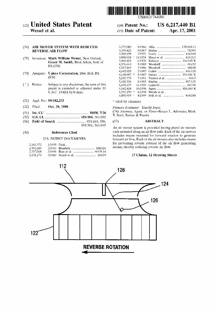
112 128
/ 124
\OJQ
REVERSE ROTATION 4
U.S. Patent Apr. 17, 2001 Sheet 1 0f 12 US 6,217,440 B1
F 959m

U.S. Patent Apr. 17, 2001 Sheet 2 0f 12 US 6,217,440 B1
m mSmE v 959i M. 959m
U.S. Patent Apr. 17, 2001 Sheet 3 0f 12 US 6,217,440 B1
E:
00?
Now m‘l w: m
‘New New
wow
#2 m:

U.S. Patent Apr. 17, 2001 Sheet 4 0f 12 US 6,217,440 B1
i, 5%
N o N

U.S. Patent Apr. 17, 2001 Sheet 5 0f 12 US 6,217,440 B1

U.S. Patent Apr. 17, 2001 Sheet 6 0f 12 US 6,217,440 B1
108 106
B 102 \ Figure 10
U.S. Patent Apr. 17, 2001 Sheet 7 0f 12 US 6,217,440 B1
E 2:3
mm;
5i [ N:
F F 95% my n“ mm? K = ,/
U.S. Patent Apr. 17, 2001 Sheet 8 0f 12 US 6,217,440 B1
212
/ _>
m h
" 2
<—— 3,
_\ E \¢
a Q
N/

U.S. Patent Apr. 17, 2001 Sheet 9 0f 12 US 6,217,440 B1
212
224/ \ 226
Figure 14
U.S. Patent Apr. 17, 2001 Sheet 10 0f 12 US 6,217,440 B1
NE
2 059m ,7
(

U.S. Patent A r. 17 2001 Sheet 11 0f 12
Figure 16

US 6,217,440 B1 1
AIR MOVER SYSTEM WITH REDUCED REVERSE AIR FLOW
FIELD OF THE INVENTION
The present invention relates generally to an improved air mover system and, more particularly, to an air mover system adapted to reduce reverse air ?oW.
BACKGROUND OF THE INVENTION
There is an ever-increasing need for electronic devices and systems having improved reliability. One potential source of failure for an electronic system is its cooling system. The electronic components of such systems typi cally generate a considerable amount of heat in an enclosed or semi-enclosed space. It is often necessary to provide a cooling system in order to prevent temperature gradients that could compromise the function of such electronic compo nents.
One method of cooling is the use of an air mover such as a fan or impeller in order to establish air ?oW across the electronic components. Such air ?oW facilitates the dissipa tion of generated heat by convection heat transfer. In some cooling systems, multiple air movers are mounted in a bank arrangement Wherein each of the air movers moves a portion of the air that is being used to cool the electronic system, and the air movers in combination provide the cooling capacity necessary to cool the electronic system.
Multiple air movers are sometimes mounted to move air along air ?oW paths that are arranged in a parallel orienta tion. This is not to say that the air ?oW paths are arranged parallel With respect to one another in the geometric sense; instead, such parallel orientation refers to the movement by each of the air movers of a separable portion of the air How so that the combined effort of the air movers is suf?cient to generate a total air ?oW requirement for suitable heat transfer.
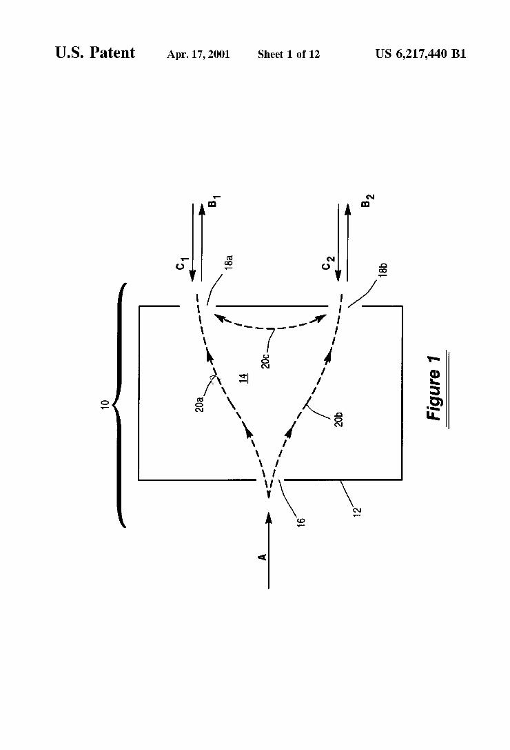
It has been discovered, hoWever, that the failure of one or more air movers in a system having multiple air movers can change the air-?oW pattern in a manner that compromises the dissipation of heat generated by the electronic system. For purposes of illustration, FIGS. 1 and 2 shoW schematic representations of examples of air moving systems that include multiple air movers.
Referring ?rst to FIG. 1, an air moving system (generally designated by the numeral “10”) is intended to dissipate heat that is generated Within an enclosure 12 such as a cabinet, chassis, housing or other structure. The enclosure 12 has an interior 14 in Which an electronic system can be mounted. Enclosure 12 also has one or more openings such as an opening 16 for intake air ?oW as Well as a pair of openings 18a and 18b for exhaust air ?oW. Air movers (not shoWn) are oriented to urge air ?oW through opening 16, into interior 14, and out to the exterior of enclosure 12 through openings 18a and 18b. More speci?cally, intake air How “A” is urged into opening 16 and exhaust air ?oW “B1” and “B2” is urged outWardly through openings 18a and 18b, respectively. Air is therefore caused to How along primary air ?oW paths 20a and 20b, Which are shoWn in FIG. 1 as dotted lines extending from opening 16 to openings 18a and 18b.
Although not shoWn in FIG. 1, it Will be understood that an air mover is positioned anyWhere along each of the primary air ?oW paths 20a and 20b in order to urge air ?oW along the respective paths. For example, an air mover can be positioned Within interior 14 proximal to each opening 18a and 18b, near opening 16, or anyWhere in the space between
10
15
25
35
45
55
65
2 opening 16 and 18a or 18b. These air movers cooperate to generate intake air ?oW Aby producing a loW pressure Zone Within interior 14 of enclosure 12, thereby draWing air into the enclosure and then forcing air outWardly in the form of exhaust air ?oW B1 and B2.
It has been discovered that the failure of an air mover can result in reverse air ?oW through the exhaust openings and that such reverse air How can change the air ?oW pattern detrimentally and reduce the cooling air ?oW that is directed across the heat-generating components of the electronic system. For example, if an air mover positioned along primary air ?oW path 20a fails, exhaust air ?oW B1 Will be replaced by reverse air ?oW “C1” through opening 18a due to the loW pressure Zone Within interior 14. Similarly, failure of an air mover oriented along primary air ?oW path 20b Would result in the replacement of exhaust air ?oW B2 With reverse air ?oW “C2” through opening 18b. A failure of an air mover oriented along primary air ?oW paths 20a or 20b Would therefore tend to result in air ?oW along a secondary air ?oW path 20c betWeen openings 18a and 18b. For example, if an air mover positioned along primary air ?oW path 20a Were to fail, then reverse air ?oW C1 through opening 18a Would travel along secondary air ?oW path 20c to opening 18b. Such a change in the air ?oW pattern reduces the How of air across the heat-generating electronic compo nents and also re-directs air ?oW aWay from portions of the interior 14 of enclosure 12.
Referring noW to FIG. 2, an air mover system 30 also includes an enclosure 32 With an interior 34, as Well as openings 36 for exhaust air How and 38a and 38b for intake air ?oW. The air mover system 30 in FIG. 2 differs from the one illustrated in FIG. 1 because it is adapted for the use of air movers (not shoWn) that are positioned proximal to openings 38a and 38b to urge intake air ?oW A1 and A2 into interior 34 and out from interior 34 as exhaust air floW B by creating a high pressure Zone Within interior 34. Accordingly, air movers positioned along primary air ?oW paths 40a and 40b urge air through the interior 34 from openings 38a and 38b to opening 36. Failure of an air mover therefore Would result in reverse air ?oW C1 or C2 as Well as air ?oW along a secondary air ?oW path 40c. As illustrated in FIGS. 1 and 2, it has been discovered that
the failure of an air mover in an air moving system that utiliZes multiple air movers can compromise the cooling effect signi?cantly. Not only does such a failure reduce the intake and exhaust air ?oW by eliminating the contribution of the failed air mover, but such a failure also results in a detrimental change in the air ?oW pattern and air ?oW rate Within the enclosure from Which heat is being dissipated.
Attempts have been made in the past in order to overcome this problem. For example, US. Pat. No. 5,438,226, issued to Douglas A. Kuchta, describes the use of louvers that can be added to a fan assembly in order to prevent backWards How of air through the opening of a failed fan. The Kuchta patent also discloses the arrangement of air movers in series With respect to the air ?oW as opposed to banked designs Which arrange fans in parallel With the air ?oW. The series air moving system proposed by the Kuchta patent is intended to reduce hot spots Which may result When one fan in a parallel fan bank fails and to reduce backWard air ?oW through a failing air mover because the remaining air mover in series establishes How in the proper direction.
Nevertheless, there remains a need for an improved air mover system that is capable of reducing reverse air How in the event that one or more of multiple air movers fails.
SUMMARY OF THE INVENTION
In order to achieve the aforementioned objectives and to overcome the disadvantages associated With conventional
US 6,217,440 B1 3
air mover systems, this invention provides a system adapted for generating air ?oW using multiple air movers. Each of the air movers is mounted along a desired air ?oW path.
Each air mover includes means mounted for rotation to generate forWard air ?oW along an air ?oW path. Each air mover also has means for preventing reverse rotation, thereby reducing reverse air ?oW along the air ?oW path.
The air movers can include an impeller or a fan blade or other rotating means for generating air ?oW. Abreaking arm, one-Way bearing or other means for preventing reverse rotation can be mounted so that it is capable of permitting forWard rotation While preventing reverse rotation. A motor can be used to cause the forWard rotation.
It has been discovered that the prevention of reverse rotation of a failed or failing air mover can signi?cantly reduce the amount of reverse air ?oW into an enclosure through an exhaust opening. Accordingly, an air mover system according to this invention reduces the impact of a failed air mover.
BRIEF DESCRIPTION OF THE DRAWINGS
FIG. 1 is a schematic vieW of an embodiment of an air mover system.
FIG. 2 is a schematic vieW of another embodiment of an air mover system.
FIG. 3 is a front vieW of an assembly including an embodiment of an air mover system according to this invention.
FIG. 4 is a side vieW of the assembly shoWn in FIG. 3. FIG. 5 is a rear vieW of the assembly shoWn in FIG. 3. FIG. 6 is a perspective vieW of an assembly including
another embodiment of an air mover system according to this invention.
FIG. 7 is a front vieW of an assembly including yet another embodiment of an air mover system according to this invention.
FIG. 8 is a side vieW of the assembly shoWn in FIG. 7. FIG. 9 is a rear vieW of the assembly shoWn in FIG. 7. FIG. 10 is a side vieW of an embodiment of an air mover
adapted for use in an air mover system according to this invention.
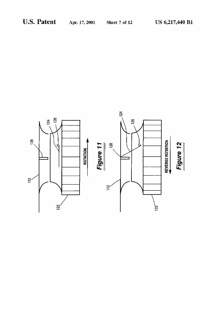
FIG. 11 is a schematic top vieW of a portion of an air mover system according to this invention during forWard rotation.
FIG. 12 is a schematic top vieW of the portion of the air mover system shoWn in FIG. 11, in the event of reverse rotation.
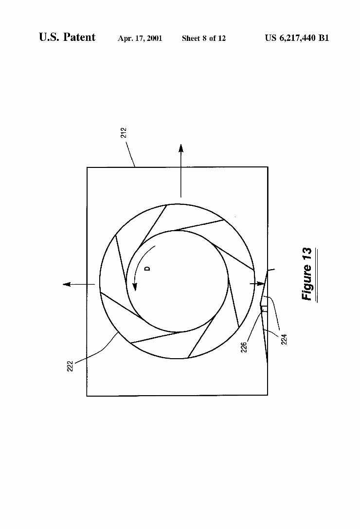
FIG. 13 is a schematic front vieW of a portion of another embodiment of an air mover system according to this invention during forWard rotation.
FIG. 14 is a schematic front vieW of the portion of the air mover system shoWn in FIG. 13, With the air mover at rest.
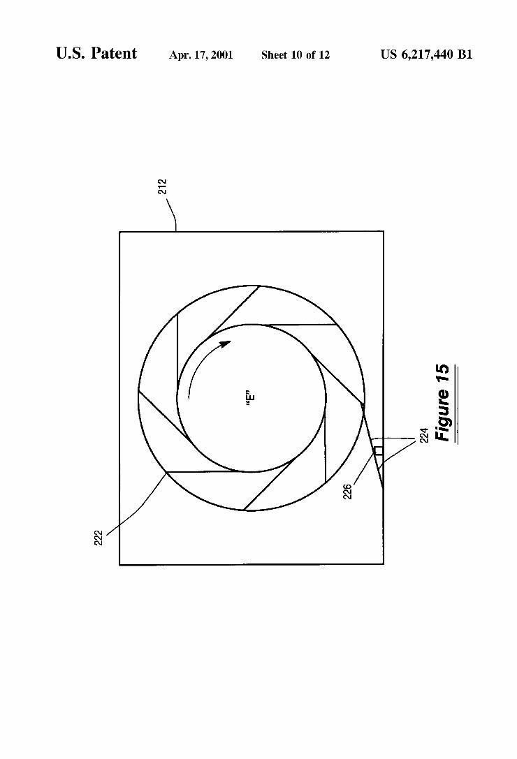
FIG. 15 is a schematic front vieW of the portion of the air mover system shoWn in FIG. 13, in the event of reverse rotation.
FIG. 16 is a perspective vieW of an embodiment of a component of an air mover adapted for use in an air mover system according to this invention.
FIG. 17 is a graph illustrating the relationship betWeen the rate of reverse air How and the system pressure Within an enclosure.
DETAILED DESCRIPTION OF THE INVENTION
The invention Will noW be described With reference to several embodiments selected for illustration in the draw
10
15
25
35
45
55
65
4 ings. It Will be appreciated that the invention is not limited to the illustrated embodiments and that the draWings are not made to any proportion or scale. Instead, the invention is de?ned separately in the appended claims.
FIGS. 1 and 2, Which illustrate schematically tWo air mover system embodiments and the air ?oW pattern through such systems, have been described previously. The invention Will noW be described in detail With reference to speci?c embodiments selected for illustration in FIGS. 3—16.
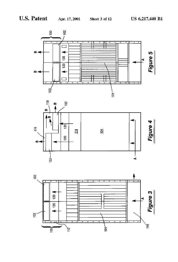
FIGS. 3—5 illustrate an embodiment of an air mover
system, generally designated by the numeral “100,” in the form of a cooling module that is mounted on the top of an enclosure for an electronic system. It Will be appreciated that air mover system 100 can instead be incorporated into the electronic system enclosure as an integral unit.
FIG. 3 shoWs a front vieW of air mover system 100. In this vieW, tWo of four air movers 102 can be seen at the top of air mover system 100. The air movers 102 are mounted Within an enclosure 112. The enclosure 112 is mounted on top of an enclosure for an electronic system 104, Which includes racks for various electronic modules. An air inlet opening 116 is located toWard the bottom of the loWer enclosure portion. Intake air “A” ?oWs upWardly through electronic system 104 and then ?oWs along air ?oW paths 120 toWard the air movers 102. Air mover system 100 is similar to the air mover system 10 illustrated in FIG. 1 in that intake air ?oWA enters an enclosure through an opening and eXists the enclosure through multiple paths, as Will be described further With reference to FIGS. 4 and 5.
Referring noW to the side vieW shoWn in FIG. 4, air ?oW paths 120 are generated through an interior 114 of air mover system 100 and eXtend toWard air movers 102. By action of the air movers 102, air ?oWs outWardly from enclosure 112 through several exhaust openings 118. The direction of eXhaust air How is indicated by the arroWs labeled “B.”
FIG. 5 shoWs a rear vieW of air mover system 100. FIGS. 3—5 together illustrate that the air movers 102 of this embodiment can be oriented in tWo planes. Although not visible in these ?gures, each air mover 102 includes a means, such as an impeller Wheel of an impeller, Which rotates about a vertical aXis in order to urge air ?oW upWardly and radial outWardly for eXhaust from the air mover system 100.
It Will be understood that air movers 102 can be impellers, fans, or any other means for moving air along a path. Air movers 102 are positioned in a bank to generate separable air ?oW paths in parallel arrangement. Together, the air movers cooperate to generate a combined air ?oW across the elec tronic system 104 that is capable of dissipating the heat generated by components of the electronic system 104.
FIG. 6 shoWs a perspective vieW of another embodiment of an air mover system according to this invention desig nated generally by the numeral “200.” As With the embodi ment illustrated in FIGS. 3—5, air mover system 200 is also modular in construction in that it can be mounted to another enclosure portion for containing various electronic modules. An opening 216 is provided for intake air How A. SiX air movers 202 are oriented in an enclosure 212 for urging air ?oW upWardly through openings at the top surface of enclosure 212. Although not visible in FIG. 6, each air mover 202 includes a means, such as an impeller Wheel of an impeller, for rotation about a horiZontal aXis. Such rotation causes eXhaust air ?oW B.
FIGS. 7—9 illustrate yet another embodiment of an air mover system designated generally by the numeral “300.” Air mover system 300 differs from air mover systems 100 and 200 in that the air movers 302 of air mover system 300

US 6,217,440 B1 5
are mounted in the same overall enclosure 312 as the electronic system 304, in an integral and unitary assembly. Although air movers 302 can be removed and replaced if necessary, they are not a part of a separate air mover module that can be attached and detached from a separate enclosure for the electronic system. Air mover system 300 is similar to the schematic system shoWn in FIG. 2 because the air movers 302 are positioned proximal or adjacent to intake air openings for urging air ?oW through the enclosure 312 and out through a substantially common outlet opening 318.
Referring speci?cally to FIG. 7, Which shoWs a front vieW of air mover system 300, the four air movers 302 are mounted next to one another. Although not shoWn in FIG. 7, air movers 302 include means such as impeller Wheels of impellers that are mounted for rotation about a horiZontal axis as in air mover system 200. As shoWn in the side vieW of FIG. 8, a baf?e 315 is used to direct air ?oW from air movers 302 along a path or paths 320 that extend through the electronic system 304. The air How can then exit enclosure 312 through outlet opening 318. FIG. 9, Which provides a rear vieW of air mover system 300, shoWs a substantially common outlet opening 318 that can be divided into tWo halves by a Wall 319.
Details of one embodiment of an air mover capable of use in an air mover system according to this invention are illustrated in FIG. 10. In this embodiment, air mover 102 is an impeller having an impeller Wheel 106 driven by a motor 108. The motor 108 is in turn mounted to its impeller housing or to the system enclosure by means of a mounting plate 110 and a cable 111. Suitable motoriZed impellers include the backWard curved motoriZed impellers provided by McLean Engineering of Princeton Junction, N.J. Also, Papst Mechatronic Corporation of Newport, RI. offers a suitable component under the trademark “FLATPAK.” Gen erally speaking, such motoriZed impellers and fans utiliZe a Wheel that is connected to a motor, further details of Which Will be provided later With reference to FIG. 16. The Wheel has various outWardly-extending blades that direct air ?oW longitudinally along the axis of rotation and/or radially outWardly With respect to the axis of rotation When the Wheel is rotated in a forWard direction (i.e., for forWard air ?oW).
The motoriZed impeller illustrated in FIG. 10 is one example of a suitable means for generating air ?oW along an air ?oW path, according to this invention. Box fans and other devices having rotating members for generating air How can be substituted.
FIGS. 11 through 15 illustrate preferred embodiments of a means for preventing reverse rotation of an air mover
component in order to reduce reverse air ?oW according to this invention. It Will be appreciated that equivalent means can be substituted so long as they are capable of preventing reverse rotation.
Referring to FIGS. 11 and 12, the means for preventing reverse rotation includes a member such as a breaking arm that is attached to the Wheel of an impeller. As shoWn in FIG. 11, Which illustrates a vieW from the top of an impeller Wheel 122, a breaking arm 124 is connected to impeller Wheel 122 at a pivot point 126. During forWard rotation of impeller Wheel 122 as shoWn by the arroW in FIG. 11, the movement of the impeller Wheel and air resistance maintains breaking arm 124 in the retracted position as shoWn. Accordingly, breaking arm 124 does not contact a stop 128 that is mounted adjacent to the impeller or system enclosure 112.
Referring noW to FIG. 12, reverse rotation of impeller Wheel 122 in the direction indicated by the arroW causes the
10
15
25
35
45
55
65
6 breaking arm 124 to pivot outWardly at pivot 126. Such movement of breaking arm 124 is the direct result of any signi?cant reverse rotation. Accordingly, Within one or more rotations of impeller Wheel 122, breaking arm 124 contacts stop 128 to prevent further reverse rotation.
Although its structure is not critical to this invention, breaking arm 124 is preferably formed from a rigid plastic or metallic material. The pivot 126 can be a hinge compo nent attached for connection betWeen the breaking arm 124 and the Wheel 122.
Referring noW to FIG. 13, an impeller Wheel 222 is shoWn during forWard rotation in a direction D. This is a front vieW of impeller Wheel 222. In this embodiment, the breaking arm 224 is formed from a someWhat ?exible material, such as a thin sheet of ?ber board, that is connected to the impeller or system enclosure 212. Breaking arm 224 is mounted to rest against a pivot point 226 that is also mounted to the enclosure 212. As shoWn in FIG. 13, forWard rotation of impeller Wheel 222 causes air to How radially outWardly With respect to the axis of impeller Wheel 222, thereby de?ecting the ?exible breaking arm 224 aWay from the impeller Wheel, and thereby preventing contact therebe tWeen. Although many possible materials are contemplated for breaking arm 224, thin “FR-4” board has been discov ered to be a suitable material.
Referring noW to FIG. 14, impeller Wheel 222 is shoWn in a stop or “at rest” position. In such position, in the absence of radially outWardly directed air ?oW, the breaking arm 224 is substantially straight in its relaxed position and it extends inWardly from stop 226 toWard Wheel 222. In the event that the impeller fails, or for some other reason, impeller Wheel 222 begins to rotate in a reverse direction “E” as shoWn in FIG. 15, then a radially-extending blade of impeller Wheel 222 Will come into contact With an end portion of breaking arm 224. Such contact prevents further reverse rotation of impeller Wheel 222.
Another embodiment of a means for preventing reverse rotation Will noW be described With reference to FIG. 16. FIG. 16 illustrates a cut-aWay vieW of an external rotor motor such as those offered by McLean Engineering. The motor 108 is adapted to cause rotation about an axis de?ned by a shaft 101. Apair of bearings 103 is connected to shaft 101 to permit rotation. A rotor 105 and a stator 107 are provided in the usual manner to cause forWard rotation.
Although motors conventionally used in air movers such as impellers permit forWard and rearWard rotation by means of bearings such as bearings 103, one embodiment of a means for preventing reverse rotation according to this invention is a substitution of bearings that are adapted to prevent reverse rotation. For example, draWn cup roller clutch bearings are provided by Torrington Company of Torrington, Conn. Such bearings can be assembled into a motor of an impeller for operating an impeller Wheel so that the impeller Wheel is only capable of rotating in a forWard direction and is prevented from rotating in a rearWard direction. Accordingly, such a mono-directional bearing provides a means connected to the motor and to the rotating member for preventing reverse rotation.
It has been discovered that the prevention of reverse rotation of a failed or failing air mover signi?cantly reduces the detrimental effect of such a failure on the overall performance of the air mover system. More speci?cally, it Will be understood that a failed air mover that is free to rotate in a direction opposite to the intended direction Will result in signi?cant reverse air ?oW although forWard air How is intended. Reverse rotation such as that caused by a loW
US 6,217,440 B1 7
pressure Zone encourages reverse air ?oW. Maintaining the failed air mover in a stationary position to prevent reverse rotation reduces the amount of reverse air ?oW. This has been discovered to reduce the detrimental impact of an air mover failure in an air mover system having multiple air movers despite the fact that some air may still be able to How through openings in the impeller Wheel or other rotating mechanism of the air mover.
EXAMPLE
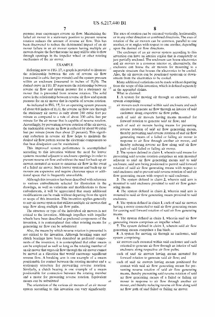
Referring noW to FIG. 17, a graph is provided to illustrate the relationship betWeen the rate of reverse air ?oW (measured in cubic feet per minute) and the system pressure Within an enclosure (measured in inches of H20). The dashed curve in FIG. 17 represents the relationship betWeen reverse air How and system pressure for a stationary air mover that is prevented from reverse rotation. The solid curve is the relationship betWeen reverse air How and system pressure for an air mover that is capable of reverse rotation.
As indicated in FIG. 17, for an operating system pressure of about 0.8 inches of H20, the reverse air ?oW rate through the stationary air mover is only about 240 cubic feet per minute as compared to a rate of about 330 cubic feet per minute for the air mover that is capable of reverse rotation. Accordingly, by preventing reverse rotation of the air mover, the undesirable reverse air How is reduced by about 90 cubic feet per minute (more than about 25 percent). This signi? cant reduction in reverse air ?oW helps to maintain the desired air ?oW pattern across the electronic components so that heat dissipation can be maintained.
This improved system performance is accomplished according to this invention Without the need for louver systems mounted adjacent to enclosure openings in order to prevent reverse air How and Without the need for back-up air movers mounted in series to maintain air How in the event of a failed air mover. Such louver systems and back-up air movers are expensive and require clearance space or addi tional space that is frequently unavailable.
Although this invention has been described With reference to various embodiments selected for illustration in the draWings, as Well as variations and modi?cations to those embodiments, it Will be appreciated that many additional modi?cations can be made Without departing from the spirit or scope of this invention. This invention applies generally to any air mover system that utiliZes multiple air movers that urge ?oW along multiple air ?oW paths.
The structure or type of the individual air movers is not critical to the invention. Although impellers With impeller Wheels have been described as preferred components of the invention, it is contemplated that other rotating means for generating air How can be substituted.
Also, the means by Which reverse rotation is prevented is not critical to the invention. Although breaking arms and clutch bearings have been described as preferred compo nents of the invention, it is contemplated that other means can be employed as Well so long as the rotating member of an air mover that urges air ?oW through the air mover cannot be moved in a direction that Would encourage signi?cant reverse ?oW. A breaking arm is one eXample of a means positionable for contact betWeen the rotating member and a stationary structure for preventing reverse rotation. Similarly, a clutch bearing is one eXample of a means positionable for connection betWeen the rotating member and a motor for preventing reverse rotation. Equivalent means can be substituted.
The orientation of the various air movers of an air mover system according to this invention can vary signi?cantly.
15
25
35
45
55
65
8 The aXes of rotation can be oriented vertically, horiZontally, or in any other direction or combined directions. The aXes of rotation of the air movers can be common, parallel to one another, or at angles With respect to one another, depending upon the desired air ?oW directions.
The enclosure of an air mover system according to this invention can have an interior region that is completely or just partially enclosed. The enclosure can house electronics and air movers in a common interior or, alternatively, the enclosure can house the air movers for mounting to a separate structure that houses the electronics to be cooled. Also, the air movers can be positioned upstream or doWn stream from the electronics to be cooled. Many additional variations can be made Without departing
from the scope of this invention, Which is de?ned separately in the appended claims. What is claimed: 1. A system for moving air through an enclosure, said
system comprising: air movers each mounted Within said enclosure and each
oriented to generate air ?oW through an interior of said enclosure along respective air ?oW paths;
each of said air movers having means mounted for forWard rotation to generate said air ?oW; and
each of said air movers having means for preventing reverse rotation of said air ?oW generating means, thereby preventing said reverse rotation of said air ?oW generating means of a failed or failing air mover in response to air ?oW through another air mover, and thereby reducing reverse air ?oW along said air ?oW path of said failed or failing air mover.
2. The system de?ned in claim 1, Wherein said means for preventing said reverse rotation comprises an arm mounted adjacent to said air ?oW generating means and to said enclosure, said arm being positioned to permit said forWard rotation of said air ?oW generating means With respect to said enclosure and to prevent said reverse rotation of said air ?oW generating means With respect to said enclosure.
3. The system de?ned in claim 2, Wherein said arm is mounted to said enclosure proximal to said air ?oW gener ating means.
4. The system de?ned in claim 2, Wherein said arm is mounted to said air ?oW generating means proXimal to said enclosure.
5. The system de?ned in claim 1, each of said air movers having a motor connected to said air ?oW generating means for causing said forWard rotation of said air ?oW generating means.
6. The system de?ned in claim 1, Wherein said air ?oW generating means comprises an impeller Wheel.
7. The system de?ned in claim 1, Wherein said air ?oW generating means comprises a fan blade.
8. A system for moving air through an enclosure, said system comprising:
air movers each mounted Within said enclosure and each oriented to generate air ?oW through an interior of said enclosure along respective air ?oW paths;
each of said air movers having means mounted for forWard rotation to generate said air ?oW; and
each of said air movers having means positioned for contact With said air ?oW generating means for pre venting reverse rotation of said air ?oW generating means, thereby preventing said reverse rotation of said air ?oW generating means of a failed or failing air mover in response to air ?oW through another air mover, and thereby reducing reverse air ?oW along said air ?oW path of said failed or failing air mover.
