air-source heat pump performance comparison in …
TRANSCRIPT

Vučković, G. D., et al.: Air-Source Heat Pump Performance Comparison in … THERMAL SCIENCE: Year 2021, Vol. 25, No. 3A, pp. 1849-1866 1849
AIR-SOURCE HEAT PUMP PERFORMANCE COMPARISON IN
DIFFERENT REAL OPERATIONAL CONDITIONS BASED ON
ADVANCED EXERGY AND EXERGOECONOMIC APPROACH
by
Goran D. VU^KOVI]*, Mirko M. STOJILJKOVI],
Marko G. IGNJATOVI], and Mi}a V. VUKI]
Faculty of Mechanical Engineering, University of Nis, Nis, Serbia Original scientific paper
https://doi.org/10.2298/TSCI200529237V
The use of air-source heat pumps (ASHP) is increasing to meet the energy needs of residential buildings, and manufacturers of equipment have permanently ex-panded the range of work and improved the efficiency in very adverse outdoor air conditions. However, in the time of a wide range of different technologies, the problem of using ASHP, from a techno-economic point of view, is constantly pre-sent. Exergetic efficiency and exergoeconomic cost no longer provide sufficiently reliable information when it is necessary to reduce the investment costs or in-crease the energy/exergetic efficiency of the component/system. This paper pre-sents comparison of ASHP in different operational conditions based on an ad-vanced exergy and exergoeconomic approach. The advanced exergy analysis splits the destruction of exergy for each individual component into avoidable and unavoidable part in order to fully understand the processes. The information of stream costs is used to calculate exergoeconomic variables associated with each system component. Irreversibility in the compressor have the greatest impact on reducing the overall system exergetic efficiency by 46.7% during underfloor heat-ing (UFH) operation and 24.53% during domestic hot water (DHW) operation. Exergy loss reduces exergetic efficiency by 5.72% UFH and 39.74% DHW. High values of exergoeconomic cost for both operating regimes are present in flows 1, 2, 3 and 4 due to high costs of production and relatively small exergy levels. The general recommendation is to set the ASHP to operate with near-optimal capaci-ties in both regimes and then reduce exergy of flows 1, 2, 5, 11, and 13.
Keywords: exergy, exergoeconomic, heat pump, UFH, DHW.
Introduction and background
The building sector has become the largest consumer of primary energy in the
world, exceeding both the industry and the transportation sectors. Heat pump technology can
deliver major economic, environmental and energy system benefits worldwide. The technolo-
gy is now becoming one of the corner stones of the energy mix for decarbonising heating and
cooling in industry, the building sector and society at large. Most heat pump systems in com-
mon use today are of the vapour-compression type 1].
___________ * Corresponding author, e-mail: [email protected]

Vučković, G. D., et al.: Air-Source Heat Pump Performance Comparison in … 1850 THERMAL SCIENCE: Year 2021, Vol. 25, No. 3A, pp. 1849-1866
Considering the heat source of a heat pump, there are three basic types: ASHP, wa-
ter-source heat pump (WSHP), and ground-source heat pump (GSHP). Yet, in order to fully
define and analyse heat pump operation, information on the heat sink is also needed. For heat
pumps, usually water or air are used as heat sinks. Concurrently, each of the above three heat
pump types has two subtypes, i.e. air-source-air-sink heat pump or air-source-water-sink heat
pump (ASWSHP). For this paper the following terms and abbreviations are used: air-to-air
heat pump (AAHP), air-to-water heat pump (AWHP), water-to-air heat pump, water-to-water
heat pump, ground-to-air heat pump, and ground-to-water heat pump.
More than 18 million households worldwide purchased heat pumps in 2018, up from
14 million in 2010. Nearly 80% of new household heat pump installations in 2017 were in
China, Japan, and the USA, which together account for around 35% of the global final energy
demand for space and water heating in residential buildings. Air source heat pumps, especial-
ly AAHP, dominate global sales for space heating in the building sector. Also, other subtypes
of ASHP, such as AWHP, and both types of WSHP and GSHP, have also expanded in recent
years. In Japan, Korea, Europe, and USA, reversible heat pumps are commonly used for heat-
ing and cooling, which often means higher heat pump performance. The adjustment of the
refrigerant flow rate reduces energy losses resulting from stops and starts in non-inverter
technologies 2].
The European Heat Pump Association statistics for 2018 reports more than 1.2 mil-
lion heat pumps (+12%) sold in Europe, leading to an installed capacity of 11.8 million units.
This installed stock contributed 29.8 Mt of carbon emission reduction and 116 TWh of energy
generated from renewable sources. It helped reduce the final energy demand by 148 TWh and
ensured a total of 54000 full time equivalent jobs in Europe. If properly connected, the current
stock of heat pumps could provide the demand side flexibility between 1 and 3.2 TWh over
the course of a year. Splitting up the overall sales development in Europe by energy source used reveals the dominance of ASHP in the market 3].
Simple installation, very good performances related to low temperature systems op-
erated in mild outside conditions (> –6 °C), low investment and maintenance costs are the
main advantages of ASHP. However, during extremely low outside temperatures, if high sup-
ply water temperatures for heating and/or DHW preparation (>45 oC) are required, and during
intermittent operation with high frequency of intermittence, ASHP efficiency decreases sig-
nificantly. This leads to increased power consumption and consequently to increased GHG
emissions and operation costs. Selection of working fluid, adjustability to electricity tariff
system, reducing heat losses, high efficiency over large span of operation temperatures are
permanent tasks for the research community and heat pump industry.
The objective of paper 4] is to demonstrate the application and usefulness of ad-
vanced exergy analysis to the evaluation of vapour compression refrigeration machines when
different one-component working fluids (R125, R134a, R22, and R717) as well as azeotropic
(R500) and zeotropic (R407C) mixtures are used, and to study the effect of different material
properties on the results of advanced exergy analysis. The advantages of an advanced exergy
analysis become more transparent and evident when an advanced exergoeconomic evaluation
is conducted, particularly for complex systems.
Dong et al. 5] proposes and investigates the solar integrated air source heat pump
(SIASHP) with working fluid R407C for radiant floor heating without water. The SIASHP for
radiant floor heating without a water pipe exposed to the outdoor environment is safe and
convenient for the narrow and vertical outdoor installation space of high-rise building users to
meet their individual demand for space heating.

Vučković, G. D., et al.: Air-Source Heat Pump Performance Comparison in … THERMAL SCIENCE: Year 2021, Vol. 25, No. 3A, pp. 1849-1866 1851
The aim of paper 6] is to develop a more physics-based model to simulate the ener-
gy performance of variable refrigerant flow (VRF) heat recovery systems. The model catego-
rizes the operations of the VRF heat recovery system into six modes based on the indoor cool-
ing/heating requirements and the outdoor unit operational states and uses novel algorithms to
capture the control logic and heat recovery between indoor units. The work presented in this
paper introduces the development, implementation, and validation of the new model. Results
show that the new model can present a satisfactory match with the measured data across all
the operation modes at sub-hourly levels.
Qui et al. 7] present an energy performance evaluation of a low global warming po-
tential refrigerant, L-41b, as a replacement for R410A. The experiment was carried out in the
climatic chamber, where the temperature was maintained within a range between 10 °C and
30 °C. The condenser outlet water temperature was controlled between 25 °C and 45 °C, fol-
lowed by maintaining the water temperature difference of 5 °C in the condenser inlet and out-
let. Adopting an internal heat exchanger has the potential of lowering the differences of per-
formance, besides approaching the L-41b performance to that attained with the use of R410A
in the existing ASHP. The refrigerant R410A is used a lot in vapour compression refrigeration
and air conditioning systems due to its high energy efficiency ratio [8].
The application of ASHP is mainly restricted by the outdoor ambient temperature,
which causes poor application effects in the severe cold regions of China. Xu et al. 9] pro-
poses an innovative hybrid energy system of a solar air collector, ASHP and energy storage
that is utilized to save energy for ultra-low energy building in severe cold regions. The results
indicate that, where the outdoor heating calculation temperature is lower than –30 °C and so-
lar energy resources are not particularly abundant, the peak inlet air temperature of the ASHP
increases by no less than 10 °C and the coefficient of performance of the system is expected
to be higher than 3.0 under extremely low temperature conditions.
Ahamed et al. 10] reviews the possibilities of research in the field of exergy analy-
sis in various usable sectors where vapour compression refrigeration systems are used. It is
found that exergy depends on evaporating temperature, condensing temperature, sub-cooling,
and compressor pressure. Exergy losses increase with the increase in suction and discharge
temperature of the compressor. For better performance of the system, compressor discharge
and suction temperature should be within 65 °C and 14 °C, respectively.
The aim of paper 11] is to investigate the feasibility of using ground source heat
pump systems in hot and dry regions. This paper introduces for the first time a techno-
economic analysis to evaluate the use of GSHP compared to the conventional ASHP in this
type of climate, in the example of Saudi Arabia. It is concluded that the GSHP is feasible,
albeit with a long payback period, typically 10-20 years, depending on the conditions, set-up,
and predictions.
Wang et al. 12] presents the energy and exergy analysis of an ASHP water heater
system using CO2/R170 mixture as an azeotropy refrigerant for sustainable development.
For a CO2/R170 ASHP water heater system, it is more important to choose a proper capil-
lary tube as throttling device to obtain better exergy efficiency than the one for an R134a
system.
Byme and Ghoubali 13] presents the evolution of an exergy analysis of ASHP for
simultaneous production of heating and cooling energies for residential buildings, hotels, or
office buildings. The experimental results show that the R290 (propane) has a higher perfor-
mance than R407C regarding exergy aspects thanks to not only the refrigerant choice but also
to a better design of components.

Vučković, G. D., et al.: Air-Source Heat Pump Performance Comparison in … 1852 THERMAL SCIENCE: Year 2021, Vol. 25, No. 3A, pp. 1849-1866
Su et al. 14] provides detailed energy, exergy and exergoeconomic analyses per-
formed for a frost-free air-conditioning system with integrated liquid desiccant dehumidifica-
tion and compressor-assisted regeneration, in which the diluted liquid desiccant can be effi-
ciently regenerated under low temperature conditions. When the proposed system is opti-
mized based on the exergoeconomics, the coefficient of performance and exergy efficiency
increase by 13.02% and 12.73%, respectively. The total product unit costs can decrease by
12.64% compared to that under the basic operation condition.
This paper analyses a vapour compression ASWSHP, or AWHP for short, in real
operating conditions. For measured operation parameters, advanced exergy analysis and exer-
goeconomic evaluation is applied in order to identify real losses and to quantify the possibili-
ties for improving operating efficiency. Having in mind that heat pumps are used in residen-
tial buildings, mainly for both space heating and DHW preparation, two different operating
modes are analysed: the heat pump operates in a low temperature mode for space heating
through the UFH system and the heat pump operates in a high temperature mode for DHW
preparation.
Description of AWHP and processes of water heating
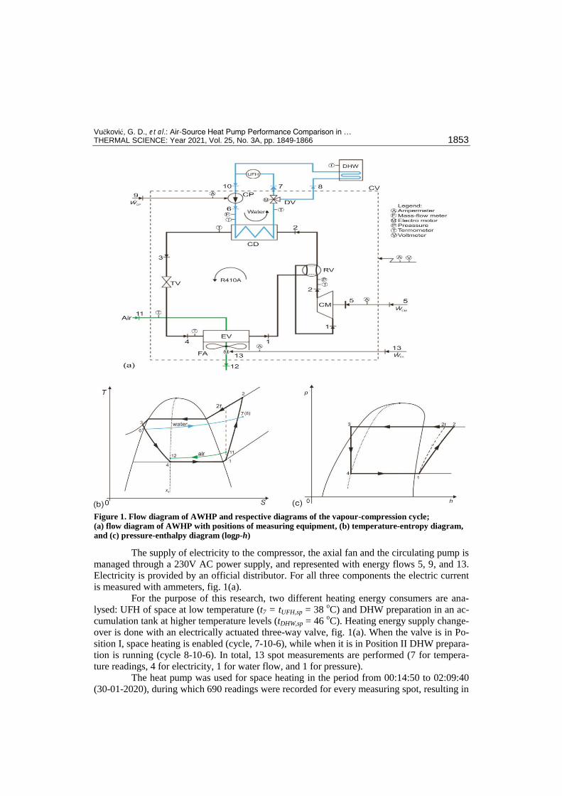
A schematic of a vapour compression AWHP is shown in fig. 1. The heat pump sys-
tem consists of two separate circuits: heat pump circuit (refrigerant/primary circuit) and heat
distribution circuit (water/secondary circuit). The refrigerant or heat transfer fluid is R410A.
The heat pump is constructed as a split-system with an outdoor and an indoor unit, connected
with copper piping for vapour and liquid phases of the refrigerant. The outdoor unit consists
of a compressor (CM), an evaporator (EV) with a fan (FA), a four-way/reversing valve (RV),
and a throttling valve (TV). The indoor unit is conceived as an integral free-standing unit with
two subsystems: hydro-module and DHW tank. The hydro-module consists of a plate heat
exchanger/condenser (CD), a three-way/diversion valve (DV), and a circulating pump (CP).
The DHW tank is conceived as a vertical accumulation-type tank with the total volume of
180 L, with a spiral heat exchanger placed in the lower zone of the tank. The accumulation
tank is factory pre-insulated in order to minimize heat losses.
The heat pump operates in the heating mode, so reversing the valve position enables
the refrigeration cycle, fig. 1. In the vapour compressor, equipped with an inverter drive (invert-
er type), slightly overheated low-pressure vapour (state 1) is compressed to a higher pressure
and temperature, which is registered with digital sensors. Superheated high pressure vapour
(state 2) enters the condenser where it condenses and slightly cools down (state 3). The tempera-
ture is measured in this point. Reducing liquid pressure is done in the throttling valve (isenthal-
pic). The cold liquid-vapour mixture (state 4) enters the evaporator where it evaporates by cool-
ing the surrounding air, heat source, figs. 1(a) and 1(b), and is slightly overheated (state 1). The
evaporation temperature is measured with a surface mounted temperature sensor. Heat transfer
in the evaporator is intensified by continuous operation of a frequency driven axial fan. In order
to maximize heat transfer from the surrounding air, during the heating operation, the axial fan
operates at full capacity. Cooled, the surrounding air leaves the evaporator in state 12.
Circulating water from the secondary circuit (used for space heating and/or DHW
preparation) is used as a heat sink. This water is heated in the condenser of the heat pump.
The condenser is constructed as a highly efficient counterflow plate heat exchanger, addition-
ally insulated in order to minimize heat losses. Circulating water flow and temperature (state
6) are measured at the condenser inlet and additionally leaving water temperature is measured
at the condenser outlet, state 7(8). The circulating pump is also frequency driven.
Vučković, G. D., et al.: Air-Source Heat Pump Performance Comparison in … THERMAL SCIENCE: Year 2021, Vol. 25, No. 3A, pp. 1849-1866 1853
The supply of electricity to the compressor, the axial fan and the circulating pump is
managed through a 230V AC power supply, and represented with energy flows 5, 9, and 13.
Electricity is provided by an official distributor. For all three components the electric current
is measured with ammeters, fig. 1(a).
For the purpose of this research, two different heating energy consumers are ana-
lysed: UFH of space at low temperature (t7 = tUFH,sp = 38 oC) and DHW preparation in an ac-
cumulation tank at higher temperature levels (tDHW,sp = 46 oC). Heating energy supply change-
over is done with an electrically actuated three-way valve, fig. 1(a). When the valve is in Po-
sition I, space heating is enabled (cycle, 7-10-6), while when it is in Position II DHW prepara-
tion is running (cycle 8-10-6). In total, 13 spot measurements are performed (7 for tempera-
ture readings, 4 for electricity, 1 for water flow, and 1 for pressure).
The heat pump was used for space heating in the period from 00:14:50 to 02:09:40
(30-01-2020), during which 690 readings were recorded for every measuring spot, resulting in
Figure 1. Flow diagram of AWHP and respective diagrams of the vapour-compression cycle; (a) flow diagram of AWHP with positions of measuring equipment, (b) temperature-entropy diagram, and (c) pressure-enthalpy diagram (logp-h)
Vučković, G. D., et al.: Air-Source Heat Pump Performance Comparison in … 1854 THERMAL SCIENCE: Year 2021, Vol. 25, No. 3A, pp. 1849-1866
a total of 8970 readings. During this operation the control parameter was the supply water
temperature with a set point of 38 oC (t7 = tUFH,sp = 38
oC). The set point was reached in 8
minutes and 30 seconds, and after this point the heat pump was in the modulating regime, i.e. the compressor and the circulating pump were adjusted to real demand. Since starting with the
modulating regime, the heat pump (set point was) reached (full control) after 55 minutes and
20 seconds, fig. 2(a). The DHW preparation ran in the period from 22:15:20 to 22:48:00 (29-
01-2020), during which 197 readings were recorded per measuring spot, resulting in a total of
2561 readings. In this case, the control parameter was the tank water temperature with a set
point of 46oC (tDHW,sp = 46
oC). The set point was reached in 36 minutes and 40 seconds, re-
sulting in the unit being switched off, fig. 2(b). The ASHP operation was monitored and the
parameters were recorded with the measuring equipment supplied by producer (for tempera-
ture thermistors with negative temperature coefficient and interchange ability ± 0.1 oC).
Methodology and modelling
When we think about energy, we consider it in terms of quantity. However, in a re-
source-constrained world, energy must also be appreciated from the point of view of quality,
which is essentially a measure of its usefulness, or its ability to do work. In order to account
for the quality and not just the quantity of energy, we need to measure exergy. The exergy
approach can identify and quantify the causes of internal inefficiencies. Exergy is the right
metric to value energy, use and resource scarcity [15].
Mass, energy, entropy, and exergy balances are employed to determine the heat
transfer, the entropy generation rate or the rate of exergy destruction. The mass, energy, en-
tropy, and exergy balance equations for a component k of an energy system in the steady-state
conditions have the form, respectively [16]:
0 i ei ek km m (1)
cv, cv,0 i ek k i i e ek kQ W m h m h (2)
g ,
.
en0j
j i ei i e e kk kj
k
Qm s m s S
T
(3)
0cv, D,0 1j i ej k i i e e kk k
jk
TQ W m e m e E
T
(4)
The total exergy of a material stream consists of four exergy components: physical,
chemical, kinetic, and potential. For this paper, the physical exergy is more interesting. The
physical exergy of a stream of matter can be defined as the maximum work (useful energy)
that can be obtained from it when taking it to the physical equilibrium (of temperature and
pressure) with the environment. For calculating exergy-related parameters, standard condi-
tions for temperature and pressure were applied, i.e. T0 = 298.15 K, p0 = 1.01325 bar. The
specific physical exergy transfer associated with a stream of matter is:
PH0 0 0j j j je e h h T s s (5)

Vučković, G. D., et al.: Air-Source Heat Pump Performance Comparison in … THERMAL SCIENCE: Year 2021, Vol. 25, No. 3A, pp. 1849-1866 1855
The last term on the right-hand side of eq. (4) represents the exergy destruction of
the kth component of the system. Exergy destruction is proportional to generated entropy, with
the surrounding temperature being the constant of proportionality. This equation is known in
the literature as the theorem of the loss of capability to do work, exergy destruction theorem
or Gouy-Stodola theorem. For the known value of the generated entropy for the kth
component
of an energy system, obtained from entropy balance (3), exergy destruction is obtained as
[16]:
D, 0 gen,k kE T S (6)
Exergy destruction in the overall system is obtained by summing up exergy destruc-
tion of every component of the system:
D, D,1
n
tot kk
E E
(7)
Energy transfer i.e. heat transfer is followed by entropy transfer, while work transfer
is performed without entropy transfer. While obtaining work from supplied heat, the general
idea is to obtain as much as possible useful work, having in mind that heat removed to a heat
sink is not a loss, but necessary compensation to obtain useful work from heat. In the case of a
heat pump, maximum efficiency is reached when heat pumps operate in the ideal Carnot cycle
with reversible processes (isentropic and isothermal processes), with efficiency dependent
only on heat source temperature (evaporation temperature) and heat sink temperature (con-
densing temperature) [17]:
conC
con evp
TCOP
T T
(8)
All real thermodynamic cycles have efficiency lower than the Carnot cycle situated
between the highest and the lowest temperature of a real cycle. The energy-based efficiency
measure (COP) of the overall heat pump system under consideration in this paper can be de-
fined as:
EUtot tot C
tot
, Q
COP COP COPW
(9)
The dividend in eq. (9) represents the heat delivered to the end-user, in the first case
it is the heat delivered to the space heating system, 7 10– ,EU UFH wQ Q m h h and in the se-
cond case the heat delivered to the DHW preparation system, EU DHW 8 10wQ Q m h h .
True information on a system’s energy performance, in the sense of thermodynamic
characteristics, is the efficiency based on exergy, i.e. exergetic (2nd
Law) efficiency. In the
fuel-product concept, exergetic efficiency is defined as the ratio between exergy of products
and fuel (component/overall system) [18]:
P, D, L, P,tot D,tot L,tottot
F, F, F,tot F,tot
1 , 1k k k
kk k
E E E E E E
E E E E
(10)
For a proper determination of exergy efficiency, it is of crucial importance to
properly define exergy of fuel and exergies of the products for every component of the system

Vučković, G. D., et al.: Air-Source Heat Pump Performance Comparison in … 1856 THERMAL SCIENCE: Year 2021, Vol. 25, No. 3A, pp. 1849-1866
and the overall system [16]. The definitions of fuel and product exergies for all components
and the overall system are given in tab. 1. In the fuel-product concept, for the steady-state,
component and system exergy balance is given by equations:
F, P, D, L, F,tot P,tot D,tot L,tot, k k k kE E E E E E E E (11)
For eqs. (10) and (11) it should be stated that when the component boundary is set at
the surrounding temperature (most often the case), the exergy loss has a zero value (ĖL,k = 0),
i.e. the complete loss of work of the component can be attributed to its exergy destruction,
while the exergy loss of the whole system remains (ĖL,tot ≠ 0). In order to determine the influ-
ence of the exergy loss of every component and the overall system on the system’s exergetic
efficiency, in this research the coefficients of exergy destruction for the component and the
system were determined with the following equations [16]:
D, L,totD, L,tot
F,tot F,tot
, k
k
E Ey y
E E (12)
When these coefficients (12) are transformed to percentages, one can determine the
percentage of influence of each component on the system’s exergetic efficiency.
In order to prioritize components for performance improvements, it is good to quan-
tify the share of a component’s exergy destruction in the total exergy destruction of the sys-
tem. This is done by determining the coefficient of the total exergy destruction of component
k [18]:
D,*D,
D,tot
kk
Ey
E (13)
Within advanced exergy analysis, the total exergy destruction of a component de-
termined by means of conventional exergy analysis is separated into the unavoidable and
avoidable part, UN AVD, D. D,k k kE E E . For determining the unavoidable part of exergy destruction,
for a component of the system, unavoidable operating conditions were pre-defined, tab. 1., as
such operating conditions cannot be reached quickly, having in mind the current technology
progress. Every component was analysed independently from the other components of the
system, and for unavoidable operating conditions, the specific unavoidable exergy destruction
was defined as: UN
D, P,k kE E . The unavoidable and avoidable parts of exergy destruction of
component k were determined, respectively, as [19]:
UN
D,UND, P,
P,
kk k
k
EE E
E
(14)
AV UND, D, D,k k kE E E (15)
The avoidable part (15) represents the real potential for component improvement.
Based on advanced exergy analysis, the maximum exergetic efficiency for every component
of the system was determined as [20]:
Vučković, G. D., et al.: Air-Source Heat Pump Performance Comparison in … THERMAL SCIENCE: Year 2021, Vol. 25, No. 3A, pp. 1849-1866 1857
max
UN
D,
P,
1
1
k
k
k
E
E
(16)
Every component will have maximum exergy efficiency when it operates with min-
imum specific unavoidable exergy destruction, the term in the brackets in eq. (16).
The scientific community is unanimous in claims that exergy is the proper thermo-
dynamic characteristic to correspond with economic principles. In this sense, for the purpose
of this research, the following exergoeconomic variables were used: exergoeconomic cost for
electricity and energy flows, exergoeconomic cost for exergy destruction and relative cost
analysis.
For determining exergoeconomic costs it is necessary to create an exergoeconomic
balance for every component of the system. The exergoeconomic balance for a component
shows that the sum of exergoeconomic costs for electricity and heat flows leaving the compo-
nent is equal to the sum of exergoeconomic costs for electricity and heat flows entering the
component and non-exergy related costs for capital investment and maintenance and opera-
tion costs, and is given in the form [16]:
CI OMw, q, q,e ie e k k k k i i k kk k
c E c W c E c E Z Z (17)
Quantities related to exergy are determined by exergy analysis, while quantities for
non-exergy related costs are determined as levelized annual costs for capital investment, oper-
ation, and maintenance costs per unit of time (year, hour, second). Since this research analysed
the existing system in real operating conditions, capital investment costs were neglected.
Exergoeconomic costs basically represent money costs of energy and material flows.
In the fuel-product concept, the component’s (system’s) exergoeconomic cost balance, for
steady-state conditions, was defined in form [20]:
CI OM CI OMP,k F,k k k P,tot F,tot tot tot , C C Z Z C C Z Z (18)
According to the previous eq. (18), for a single component and for the overall sys-
tem, for steady-state conditions, exergoeconomic cost of products equals the sum of exer-
goeconomic costs for resources and non-exergy related costs for capital investment, mainte-
nance, and operation.
Exergoeconomic cost of exergy destruction represents the cost of fuel additionally
provided to a single component/the overall system, in order to offset the disturbance caused
by exergy destruction within the component/system. It is determined as the product of specific
exergoeconomic fuel cost and exergy destruction of the given component/system [18]:
D, F, D, P, D,tot F,tot D,tot P,totconst. , c onst. k k k kC c E E C c E E (19)
Relative cost differences as an exergoeconomic variable, representing a relative in-
crease in average costs per unit of exergy, between fuel and product for the compo-
nent/system was determined according [16]:
P, F, P,tot F,tottot
F, F,tot
, k k
kk
c c c cr r
c c
(20)
It is desirable that the value of the relative cost analysis is as low as possible.

Vučković, G. D., et al.: Air-Source Heat Pump Performance Comparison in … 1858 THERMAL SCIENCE: Year 2021, Vol. 25, No. 3A, pp. 1849-1866
Results and discussions
The results presented in this paper are related to a low temperature AWHP with the
nominal capacity of the outdoor unit of 6 kW and a single-phase electricity connection (model
ERLQ006CV3) and the indoor unit with an integrated hydro-module and a 180 L. The DHW
tank (model EHVX08S18CB3V).
Table 1 gives the overview of equations for calculating exergy of fuels, exergy of
products, as well as real and unavoidable operating conditions for splitting exergy destruction
into the avoidable and unavoidable part, for a single component and the overall system.
A comparison of AWHP performance in real operating conditions is done for two
distinctive regimes.
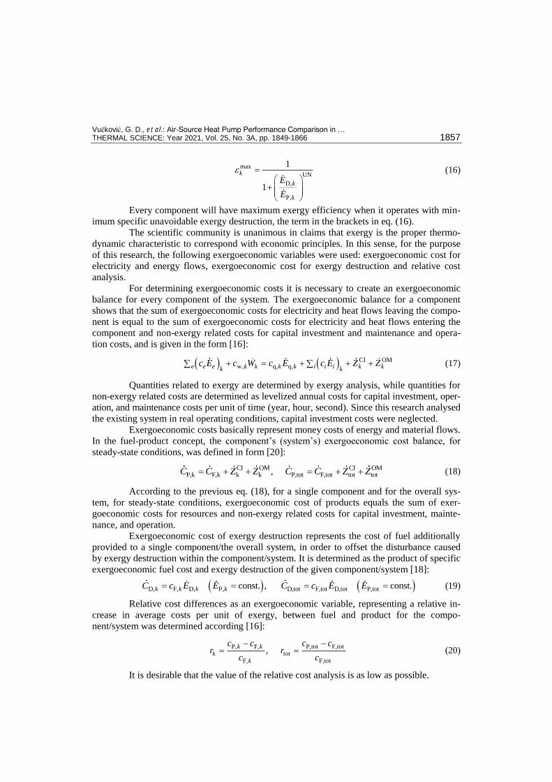
During UHF operation, fig. 2(a)., the objective was to reach the space heating sys-
tem supply water temperature of 38 oC (t7 = tUFH,sp = 38
oC). During start-up, this temperature
was 35.7 oC. The heat pump compressor started at full capacity leading to a permanent tem-
perature rise of vapour at the compressor outlet from 54.5 oC to the maximum of 93.0
oC.
Condensing temperature was increased in this period from 38.1 oC to the maximum of 44.6
oC.
Supply water temperature was reached in 8.5 minutes. The set-point was exceeded due to the
system’s inertia, and this triggered the modulating operation of the heat pump, i.e. the com-
pressor power supply was changed according to the actual heat demand.
The modulating operation led to a decrease in heat capacity (at first vapour tempera-
ture at the compressor outlet was steadily decreasing, leading to a condensing temperature
decrease, and later to a further decrease in temperature variations), and after 55.5 minutes, the
heat pump reached full control, with temperature set-point deviations smaller than ±0.4 oC,
i.e. ≤ 1.0%. Vapour temperature at the compressor outlet was steadily around 60 oC. Heat
source (outdoor air, t11) temperature during the same time was in the range from 5.0 oC to
–0.5 oC and it was followed by evaporating temperature and, since from eq. (8) it is desirable
to have a smaller difference between condensing and evaporating temperature, led to the heat
pump performance increase (∆tlift COPC).
During DHW preparation, fig. 2(b)., the objective was to reach DHW tank tempera-
ture tDHW,sp = 46 oC, and during this operation the tank was treated as the end-user. At the be-
ginning of operation, DHW tank temperature was 34.2 oC (this value can be treated as the
ghost value due to the sensor position and stationary conditions), and immediately after the
start it dropped to 29.9 oC after 7 minutes of operation (this temperature represents the actual,
real temperature for the analysis). The heat pump compressor started at full capacity leading
to a permanent temperature rise of vapour at the compressor outlet from 64.5 oC to the maxi-
mum of 96.5 oC, and after certain time this temperature was steadily around 90
oC. Condens-
ing temperature increased from 37.0 oC to the maximum of 56.9
oC.
Table 1. Exergy of fuel, exergy of product, real and unavoidable operational conditions (OC) for
components and system
Component Exergy of fuel Exergy of product Real OC Unavoidable OC
Compressor ẆCondenser
Throttling valve
Evaporator ẆCirculation pump Ẇ
Heat pump Ẇ
Vučković, G. D., et al.: Air-Source Heat Pump Performance Comparison in … THERMAL SCIENCE: Year 2021, Vol. 25, No. 3A, pp. 1849-1866 1859
Figure 2. Temperature profiles of process fluids during real operating conditions;
(a) low temperature UFH and (b) DHW heating (for colour image see journal web site)
During the same time, heat source temperature (outdoor air, t11) was between 1.0 oC
and 8.0 oC, and it was followed by evaporating temperature. Unlike UHF operation, in this
situation the heat pump did not enter the modulating operation since it shut down after reach-
ing the setpoint value.
Measurements in the selected points of the described processes, fig. 1, were used for
calculating thermal, exergy and exergoeconomic variables. The CoolProp software used in all
calculation of thermodynamic analysis [21]. Besides thermal measurements (temperature,
pressure, and flow), electricity consumption was recorded. For every parameter, basic statis-
tics were applied and the average value, median and standard deviation were calculated based
on the following expressions [22]:
1
1 N
ii
X XN
(21)
1
, where is 1 / 2 and odd number
, where is / 2 and even number2
j
X j j
X j N N
µ X Xj N N
(22)
2
1
1 N
X ii
X XN
(23)
Statistical analysis of the measurement reveals that for both types of operation
enough data was obtained, and that average values could be used for further analysis. Besides these statistical values, tab. 2, gives the overview of values of the most im-
portant thermodynamic, exergy and exergoeconomic parameters of the overall system, for
both types of operation.
Performance metrics based on energy (COP) during UFH operation varies around
the mean value of 3.77 during the entire operating period, and maintains the trend of a con-
stant value, fig. 3(a). Frequency distribution of experimental results is concentrated around this

Vučković, G. D., et al.: Air-Source Heat Pump Performance Comparison in … 1860 THERMAL SCIENCE: Year 2021, Vol. 25, No. 3A, pp. 1849-1866
mean value, since the standard deviation is 0.36 or 9.55%. Out of 690 values (NUFH = 690), COP
for 435 of them (63%) is within the interval of one standard deviation ([ ̅̅ ̅̅ ̅̅ ± σUHF]) while
the offset of the mean value to the median value is only 0.53%, tab. 2. A greater distance from
the mean value was observed during the system start, when AWHP operated at full capacity and
when condensing temperature reached 44.6 oC.
The operating and maintenance cost rate for each component was calculated as a
levelized annual cost for a period of 15 years with the annual escalation rate of 6% and the
rate of return of 12% using the real present operating and maintenance cost for 3650 working
hours per year.
Figure 3. The energy-based efficiency measure of the overall heat pump system (real COP and Carnot COP) as a function of the difference between condensing and evaporating temperature;
(a) low temperature UFH and (b) DHW heating (for colour image see journal web site)
On the other hand, during DHW operation, fig. 3(b)., there was a significant drop of
the COP value at the end (COPDHW,min = 3.01) compared to the system start when it had the
maximum value (COPDHW,max = 4.71). The standard deviation of COP during this type of op-
eration was higher compared to UHF operation and is 13.67%. Out of 197 measured values,
160 were within one standard deviation from the mean value ([ ̅̅ ̅̅ ̅̅ ± σDHW]) thus giving
the Gaussian distribution. The difference between the mean and the median value was slightly
bigger and is around 5.4%.
Table 2. Statistical values of selected thermodynamic, exergy and exergoeconomic parameters for the overall system
Parameters Unit Low temperature UFH DHW heating
Average Median St.dev. Max. Min. Average Median St.dev. Max. Min.
[°C] 3.41 4.00 1.33 5.00 -0.50 3.84 2.00 2.66 8.00 1.00
[°C] 38.86 38.50 1.68 44.60 36.80 45.33 46.20 5.00 53.90 33.50
[ ] 3.77 3.75 0.36 4.80 3.02 3.51 3.32 0.48 4.71 3.01
[kW] 0.79 0.62 0.32 1.61 0.46 3.61 4.15 0.94 4.79 1.91
[kW] 0.14 0.11 0.06 0.29 0.08 0.56 0.63 0.30 0.93 0.15
[kW] 0.61 0.48 0.27 1.36 0.33 1.63 1.67 0.38 2.33 0.87
[kW] 0.04 0.04 0.01 0.07 0.03 1.42 1.64 0.36 1.90 0.88
[%] 18.09 17.50 3.35 27.51 10.85 14.29 14.21 5.31 22.35 7.72
[€/h] 0.06 0.06 0.00 0.06 0.06 0.06 0.06 0.00 0.06 0.06
[€/h] 0.05 0.04 0.02 0.09 0.03 0.13 0.15 0.03 0.18 0.07
[€/h] 0.11 0.09 0.02 0.15 0.09 0.19 0.20 0.03 0.23 0.12
[€/h] 0.04 0.03 0.02 0.08 0.02 0.06 0.06 0.01 0.09 0.03
[ ] 11.97 12.65 3.07 17.89 5.50 11.44 8.36 6.15 22.40 5.16

Vučković, G. D., et al.: Air-Source Heat Pump Performance Comparison in … THERMAL SCIENCE: Year 2021, Vol. 25, No. 3A, pp. 1849-1866 1861
The observed difference between the mean and the median value, during DHW op-
eration can be seen by comparing figs. 3(a) and 3(b)., where in the first case the temperature
difference between condensing and evaporating temperature is almost constant, fig. 3(a),
while in the second case this difference is constantly increasing, fig. 3(b). These differences
are directly followed with Carnot efficiency which increases with a decrease in ∆tlift, fig. 3(a),
and vice versa, fig. 3(b). From the energy point of view, UFH operation of AWHP is 6.9%
more efficient compared to DHW operation.
Exergy efficiency of the observed system experiences a slight decrease with a fuel
exergy increase during UFH operation, fig. 4(a), as expected since higher values of fuel exer-
gy are common for the AWHP start (the compressor and condenser efficiencies have mini-
mum values). After adjusting the compressor output to real energy needs, fig. 2, exergy effi-
ciency of the components and AWHP maintained constant values, fig. 4(a). Having in mind
that during DHW operation AWHP capacity steadily increased, fig. 2(b)., fuel exergy repli-
cated this trend. The system’s exergy efficiency rose to the maximum value, and then de-
creased to the minimum, fig. 4(b). It is interesting that for fuel exergy of 3.9-4.1kW, when
exergy efficiency reached the maximum value, at the same time AWHP output capacity
reached its maximum value (based on the manufacturer catalogue) [23]. With a further in-
crease in fuel exergy, irreversibilities in the compressor increased, which was followed by a
drop in AWHP efficiency.
Figure 4. Recorded and maximum exergetic efficiency of the components and the system as a function
of fuel exergy of the overall system; (a) low temperature UFH and (b) DHW heating (for colour image see journal web site)
The application of advanced exergy analysis revealed that the circulating pump has
the lowest exergy efficiency (cca 40%) which can be doubled, but since it has small absolute
values, its impact on AWHP exergetic efficiency is minimal. For improving the overall sys-
tem’s exergetic efficiency it is far more important to increase exergetic efficiency of the com-
pressor, condenser, and evaporator, which, on average, can be increased by 9.23%, 4.41%,
and 2.72%, respectively, during UFH operation and 3.04%, 3.88%, and 5.22%, respectively,
during DHW operation.
Figure 5(a) shows that the mean value of exergy efficiency during UHF operation
(18.09%) is 21% larger than DHW operation (14.29%), which can lead to the conclusion that
during this type of operation AWHP operates with more favourable operating conditions. Du-
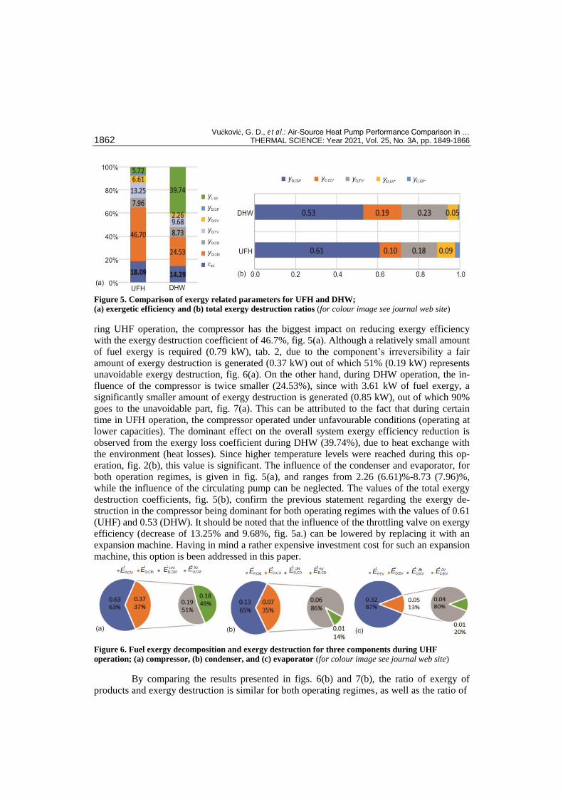
Vučković, G. D., et al.: Air-Source Heat Pump Performance Comparison in … 1862 THERMAL SCIENCE: Year 2021, Vol. 25, No. 3A, pp. 1849-1866
Figure 5. Comparison of exergy related parameters for UFH and DHW; (a) exergetic efficiency and (b) total exergy destruction ratios (for colour image see journal web site)
ring UHF operation, the compressor has the biggest impact on reducing exergy efficiency
with the exergy destruction coefficient of 46.7%, fig. 5(a). Although a relatively small amount
of fuel exergy is required (0.79 kW), tab. 2, due to the component’s irreversibility a fair
amount of exergy destruction is generated (0.37 kW) out of which 51% (0.19 kW) represents
unavoidable exergy destruction, fig. 6(a). On the other hand, during DHW operation, the in-
fluence of the compressor is twice smaller (24.53%), since with 3.61 kW of fuel exergy, a
significantly smaller amount of exergy destruction is generated (0.85 kW), out of which 90%
goes to the unavoidable part, fig. 7(a). This can be attributed to the fact that during certain
time in UFH operation, the compressor operated under unfavourable conditions (operating at
lower capacities). The dominant effect on the overall system exergy efficiency reduction is
observed from the exergy loss coefficient during DHW (39.74%), due to heat exchange with
the environment (heat losses). Since higher temperature levels were reached during this op-
eration, fig. 2(b), this value is significant. The influence of the condenser and evaporator, for
both operation regimes, is given in fig. 5(a), and ranges from 2.26 (6.61)%-8.73 (7.96)%,
while the influence of the circulating pump can be neglected. The values of the total exergy
destruction coefficients, fig. 5(b), confirm the previous statement regarding the exergy de-
struction in the compressor being dominant for both operating regimes with the values of 0.61
(UHF) and 0.53 (DHW). It should be noted that the influence of the throttling valve on exergy
efficiency (decrease of 13.25% and 9.68%, fig. 5a.) can be lowered by replacing it with an
expansion machine. Having in mind a rather expensive investment cost for such an expansion
machine, this option is been addressed in this paper.
Figure 6. Fuel exergy decomposition and exergy destruction for three components during UHF
operation; (a) compressor, (b) condenser, and (c) evaporator (for colour image see journal web site)
By comparing the results presented in figs. 6(b) and 7(b), the ratio of exergy of
products and exergy destruction is similar for both operating regimes, as well as the ratio of
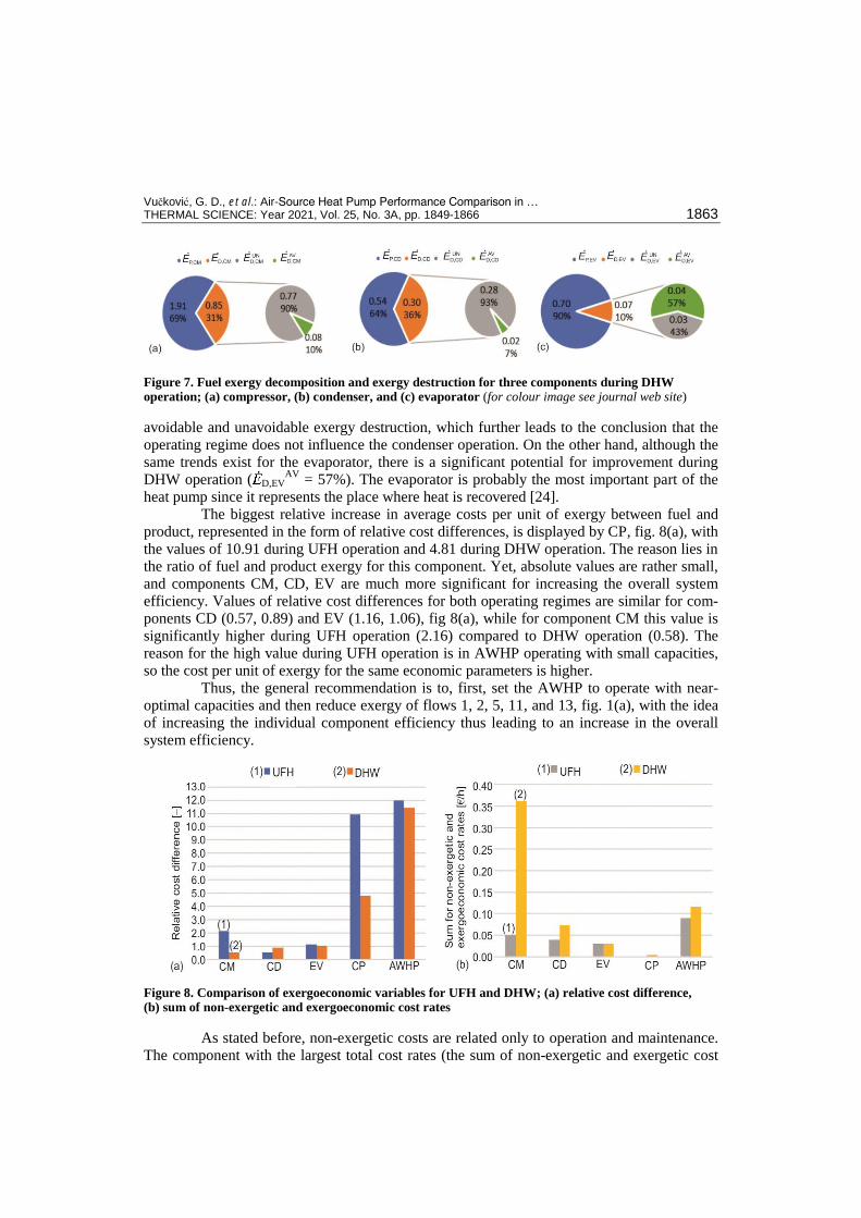
Vučković, G. D., et al.: Air-Source Heat Pump Performance Comparison in … THERMAL SCIENCE: Year 2021, Vol. 25, No. 3A, pp. 1849-1866 1863
Figure 7. Fuel exergy decomposition and exergy destruction for three components during DHW operation; (a) compressor, (b) condenser, and (c) evaporator (for colour image see journal web site) avoidable and unavoidable exergy destruction, which further leads to the conclusion that the
operating regime does not influence the condenser operation. On the other hand, although the
same trends exist for the evaporator, there is a significant potential for improvement during
DHW operation ( D,EVAV
= 57%). The evaporator is probably the most important part of the
heat pump since it represents the place where heat is recovered [24].
The biggest relative increase in average costs per unit of exergy between fuel and
product, represented in the form of relative cost differences, is displayed by CP, fig. 8(a), with
the values of 10.91 during UFH operation and 4.81 during DHW operation. The reason lies in
the ratio of fuel and product exergy for this component. Yet, absolute values are rather small,
and components CM, CD, EV are much more significant for increasing the overall system
efficiency. Values of relative cost differences for both operating regimes are similar for com-
ponents CD (0.57, 0.89) and EV (1.16, 1.06), fig 8(a), while for component CM this value is
significantly higher during UFH operation (2.16) compared to DHW operation (0.58). The
reason for the high value during UFH operation is in AWHP operating with small capacities,
so the cost per unit of exergy for the same economic parameters is higher.
Thus, the general recommendation is to, first, set the AWHP to operate with near-
optimal capacities and then reduce exergy of flows 1, 2, 5, 11, and 13, fig. 1(a), with the idea
of increasing the individual component efficiency thus leading to an increase in the overall
system efficiency.
Figure 8. Comparison of exergoeconomic variables for UFH and DHW; (a) relative cost difference, (b) sum of non-exergetic and exergoeconomic cost rates
As stated before, non-exergetic costs are related only to operation and maintenance.
The component with the largest total cost rates (the sum of non-exergetic and exergetic cost
Vučković, G. D., et al.: Air-Source Heat Pump Performance Comparison in … 1864 THERMAL SCIENCE: Year 2021, Vol. 25, No. 3A, pp. 1849-1866
rates) is CM, which should have the priority for improvements. The total cost rates for CM,
during DHW operation, have the value of 0.36 EUR/h, fig. 8(b), due to high values of this
component’s fuel exergy. During UFH operation this value drops to 0.05 EUR per hours. The
same applies for this exergoeconomic variable, as for the relative cost difference: the next
components for improvements are CD and EV, fig. 8(b). The throttling valve as the compo-
nent that serves the others and whose replacement with an expansion machine is not economi-
cally viable is not treated.
Conclusions
Scientific methods based on exergy can be used for energy system analysis equally
at the component and system level. Results of conventional, energy analysis and advanced
exergy analysis and exergoeconomic evaluation lead to the following conclusions for the de-
scribed energy system (AWHP):
From the energy analysis standpoint, it operates with satisfying performance for both op-
erating regimes ( ̅̅ ̅̅ ̅̅ ̅̅ ̅̅ ̅̅
).
Exergetic efficiency has a rather small value for both cases ( ̅ ̅ ), with the largest influence during UHF operation attributed to irreversibilities in
the compressor, and to irreversibilities in the compressor and exergy loss during DHW op-
eration.
The AWHP has high exergoeconomic costs of lost (destroyed) available work
( ̅ €/h and ̅ €/h), which represents 76% of exer-
goeconomic cost for fuel during UHF operation and 45% during DHW operation.
These results show that AWHP is over-dimensioned for UHF operation as described
but it has enough capacity for DHW operation. Destroyed work in the compressor has the
greatest impact on reducing the overall system’s exergetic efficiency with 46.7% during UFH
operation and 24.53% during DHW operation. Exergy destruction of the other components
contributes with 29.49% (UFH) and 21.44 (DHW). Exergy loss reduces exergetic efficiency
by 5.72% (UFH) and 39.74% (DHW). High values of exergoeconomic cost for both operating
regimes are present in flows 1-4 due to high costs of production and relatively small exergy
levels.
Advanced exergy analysis shows that 51% of lost work in CM is unavoidable during
UFH, and 90% is unavoidable during DHW operation, while the rest can be avoided by ap-
plying available state-of-the-art technologies.
To increase exergy/energy efficiency of AWHP it is of crucial importance to reduce
internal irreversibilities of the compressor while operating with lower capacities, which re-
duces losses to the environment, and finally operates the system at the design/nominal operat-
ing conditions.
Analysis of individual components’ exergetic efficiency and the overall system’s
exergetic efficiency reveals that the selection of the heat pump should be adjusted to end us-
ers, reducing the impact of the compressor’s exergy destruction coefficient. Further, it is re-
vealed that condensing temperature should be as low as possible, which is the same conclu-
sion as the one derived from conventional energy analysis.
Acknowledgment
This research was financially supported by the Ministry of Education, Science and
Technological Development of the Republic of Serbia (No. 451-03-68/2020-14200109).

Vučković, G. D., et al.: Air-Source Heat Pump Performance Comparison in … THERMAL SCIENCE: Year 2021, Vol. 25, No. 3A, pp. 1849-1866 1865
Nomenclature
c – cost per unit exergy [€/GJ] – exergoeconomic cost rate [€/h]
e – specific exergy [kJkg–1] – exergy flow rate [kW]
h – specific enthalpy [kJkg–1] ṁ – mass flow rate [kgs–1] p – pressure [bar] Q – heat transfer rate [kW] r – relative cost difference [–] s – specific entropy [kJkg–1K–1] Ṡ – entropy rate [WK–1] t – temperature [°C] T – absolute temperature [K] Ẇ – power or work rate [kW] X – current variable y – exergy ratio [–]
– non-exergy cost rate [€h–1]
Greek symbols
∆ – difference – exergetic efficiency
µ – median – standard deviation
Subscripts
C – Carnot CD – condenser CM – compressor CP – circulation pump cv – control volume con – condensation D – destruction
e – outlet stream EU – end-user EV – evaporator evp – evaporation F – fuel gen – generated i – inlet stream, current measure j – stream k – system component lift – from condensation to evaporation L – loss max – maximal min – minimal N – total number of measures P – product q – heat transfer sp – set point TV – throttling valve tot – overall system w – generating power, water X – current variable 0 – environment
Superscripts
AV – avoidable CI – capital investment max – maximal OM – operating and maintenance UN – unavoidable PH – physical * – total ‾ – arithmetic average
References
[1] Moran, M., Shapiro, H., Fundamentals of Engineering Thermodynamics, John Wiley & Sons Ltd., West Sussex, UK, 2006
[2] ***, https://www.iea.org/reports/tracking-buildings/heat-pumps [3] ***, https://www.ehpa.org/market-data/market-overview/ [4] Morosuk, T., Tsatsaronis, G., Advanced Exergetic Evaluation of Refrigeration Machines Using Different
Working Fluids, Energy, 34 (2009), 12, pp. 2248-2258 [5] Dong, X., et al., Energy and Exergy Analysis of Solar Integrated Air Source Heat Pump for Radiant
Floor Heating Without Water, Energy and Buildings, 142 (2017), May, pp. 128-138 [6] Zhang, R., et al., A Novel Variable Refrigerant Flow (VRF) Heat Recovery System Model:
Development and Validation, Energy and Buildings, 168 (2018), June, pp. 399-412 [7] Qui, J., et al., Experimental Investigation of L-41b as Replacement for R410A in a Residential Air-
Source Heat Pump Water Heater, Energy and Buildings, 199 (2019), Sept., pp. 190-196 [8] Xu, S., et al., Experimental Study on R1234yf Heat Pump at Low Ambient Temperature Comparison
with Other Refrigerants, Thermal Science, 23 (2019), 6B, pp. 3877-3886 [9] Xu, W., et al., Feasibility and Performance Study on Hybrid Air Source Heat Pump System for Ultra-Low
Energy Building in Severe Cold Region of China, Renewable Energy, 146 (2020), Feb., pp. 2124-2133 [10] Ahamed, U. J., et al., A Review on Exergy Analysis of Vapor Compression Refrigeration System,
Renewable and Sustainable Energy Reviews, 15 (2011), 3, pp. 1593-1600 [11] Alshehri, F., et al., Techno-Economic Analysis of Ground and Air Source Heat Pumps in Hot Dry
Climates, Journal of Building Engineering, 26 (2019), Nov., 100825

Vučković, G. D., et al.: Air-Source Heat Pump Performance Comparison in … 1866 THERMAL SCIENCE: Year 2021, Vol. 25, No. 3A, pp. 1849-1866
[12] Wang, D., et al., Energy and Exergy Analysis of an Air-Source Heat Pump Water Heater System Using CO2/R170 Mixture as an Azeotropy Refrigerant for Sustainable Development, International Journal of Refrigeration, 106 (2019), Oct., pp. 628-638
[13] Byme, P., Ghoubali, R., Exergy Analysis of Heat Pumps for Simultaneous Heating and Cooling, Applied Thermal Engineering, 149 (2019), Feb., pp. 414-424
[14] Su, W., et al., Performance Investigation on a Frost-Free Air Source Heat Pump System Employing Liquid Desiccant Dehumidification and Compressor-Assisted Regeneration Based on Exergy and Exergoeconomic Analysis, Energy Conversion and Management, 183 (2019), Mar., pp. 167-181
[15] ***, https://www.scienceeurope.org/media/0vxhcyhu/se_exergy_brochure.pdf [16] Bejan, A., et al., Thermal Design and Optimization, John Wiley & Sons, Inc., New York, USA, 1996 [17] Cuhla, O., et al., Heat Exchanger Applications in Wastewater Source Heat Pumps for Buildings: A Key
Review, Energy and Buildings, 104 (2015), Oct., pp. 215-232 [18] Mergenthaler, P., et al., Application of Exergoeconomic, Exergoenvironmental, and Advanced Exergy
Analysis to Carbon Black Production, Energy, 137 (2017), Oct., pp. 898-907 [19] Ebrahimi, M., et al., Conventional and Advanced Exergy Analysis of a Grid Connected Underwater
Compressed Air Energy Storage Facility, Applied Energy, 242 (2019), May, pp 1198-1208 [20] Kelly, S., Energy System Improvement Based on Endogenous and Exogenous Exergy Destruction, Ph.
D. thesis, TU Berlin, Berlin, Germany, 2008 [21] ***, http://www.coolprop.org/index.html [22] Bulatović, J., Statistical Processing of Measurement Results (in Serbian), Edvard Kardelj, Niš, Serbia,
1982 [23] ***, https://www.daikin.rs/sr_rs/products/ERLQ-CV3.table.html [24] Nyers, A., et al., Dynamic Behavior of a Heat Pump Coaxial Evaporator Considering the Phase Border`S
Impact on Convergence, Facta Universitatis, Series: Mechanical Engineering, 16 (2018), 2, pp. 249-259
Paper submitted: May 29, 2020 © 2021 Society of Thermal Engineers of Serbia. Paper revised: July 14, 2020 Published by the Vinča Institute of Nuclear Sciences, Belgrade, Serbia. Paper accepted: August 7, 2020 This is an open access article distributed under the CC BY-NC-ND 4.0 terms and conditions.