heat pump cycle
DESCRIPTION
heat pump cycleTRANSCRIPT
10CHAPTERCHAPTER
RefrigerationCycles

Refrigerator and Heat Pump ObjectivesRefrigerator and Heat Pump Objectives10-1
(fig. 10-1)
The objective of a refrigerator is to remove heat (QL) from the cold medium; the objective of a heat pump is to supply heat (QH) to a warm medium

Some Basic DefinitionsSome Basic Definitions
• The transfer of heat from lower temperature regions to higher temperature ones is called refrigeration.
• Devices that produce refrigeration are called refrigerators, and the cycles on which they operate are called refrigeration cycles.
• The working fluids used in refrigerators are called refrigerants.
• Refrigerators used for the purpose of heating a space by transferring heat from a cooler medium are called heat pumps.
10-14
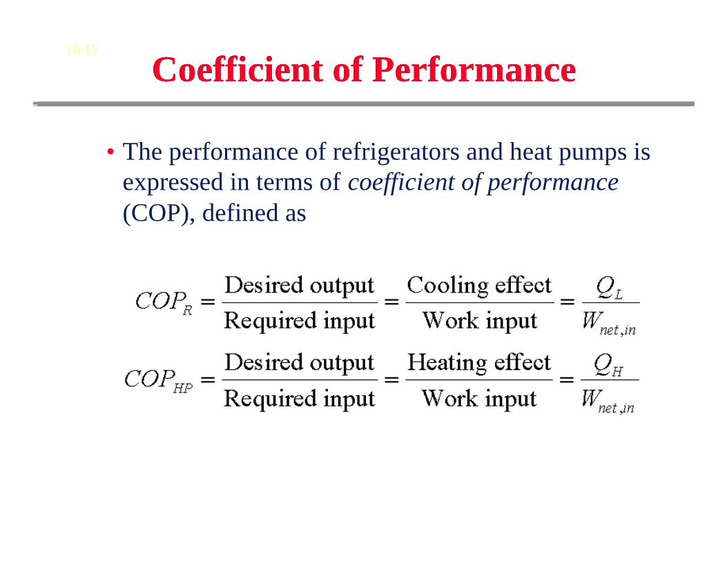
Coefficient of PerformanceCoefficient of Performance
• The performance of refrigerators and heat pumps is expressed in terms of coefficient of performance (COP), defined as
10-15
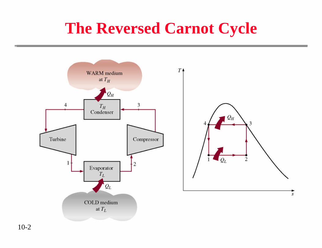
The Reversed Carnot Cycle
10-2
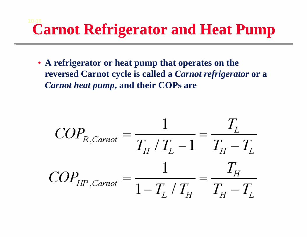
Carnot Refrigerator and Heat PumpCarnot Refrigerator and Heat Pump
• A refrigerator or heat pump that operates on the reversed Carnot cycle is called a Carnot refrigerator or aCarnot heat pump, and their COPs are
10-16

Why not use the reversed CarnotRefrigeration Cycle
Why not use the reversed CarnotRefrigeration Cycle
• Easier to compress vapor only and not liquid-vapor mixture
• Cheaper to have irreversible expansion through an expansion valve
10-16
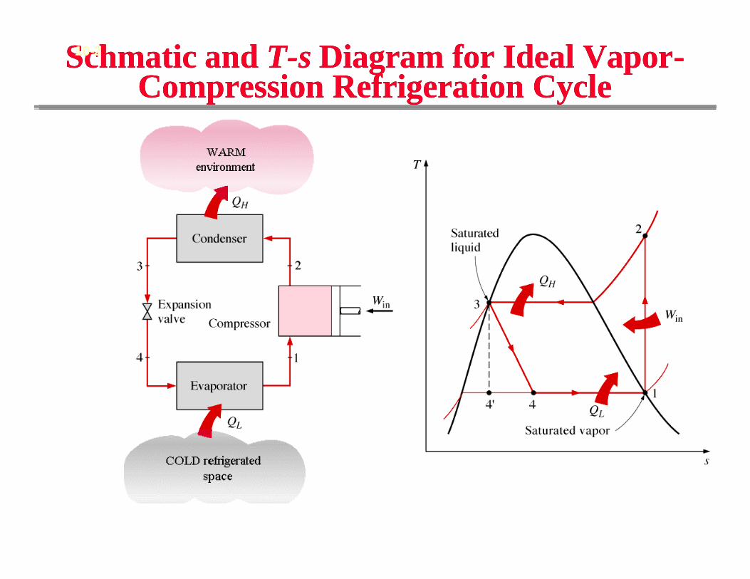
Schmatic and T-s Diagram for Ideal Vapor-Compression Refrigeration Cycle
Schmatic and T-s Diagram for Ideal Vapor-Compression Refrigeration Cycle
10-2
(Fig. 10-3)
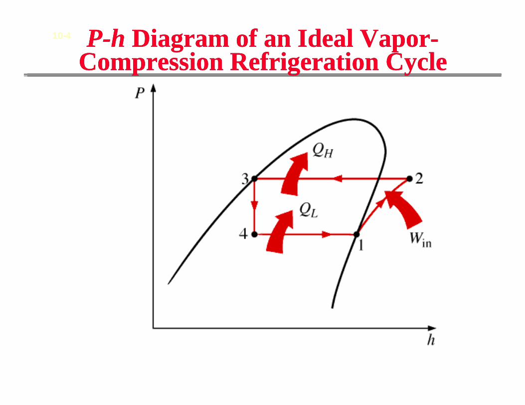
P-h Diagram of an Ideal Vapor-Compression Refrigeration CycleP-h Diagram of an Ideal Vapor-
Compression Refrigeration Cycle
(Fig. 10-5)
10-4
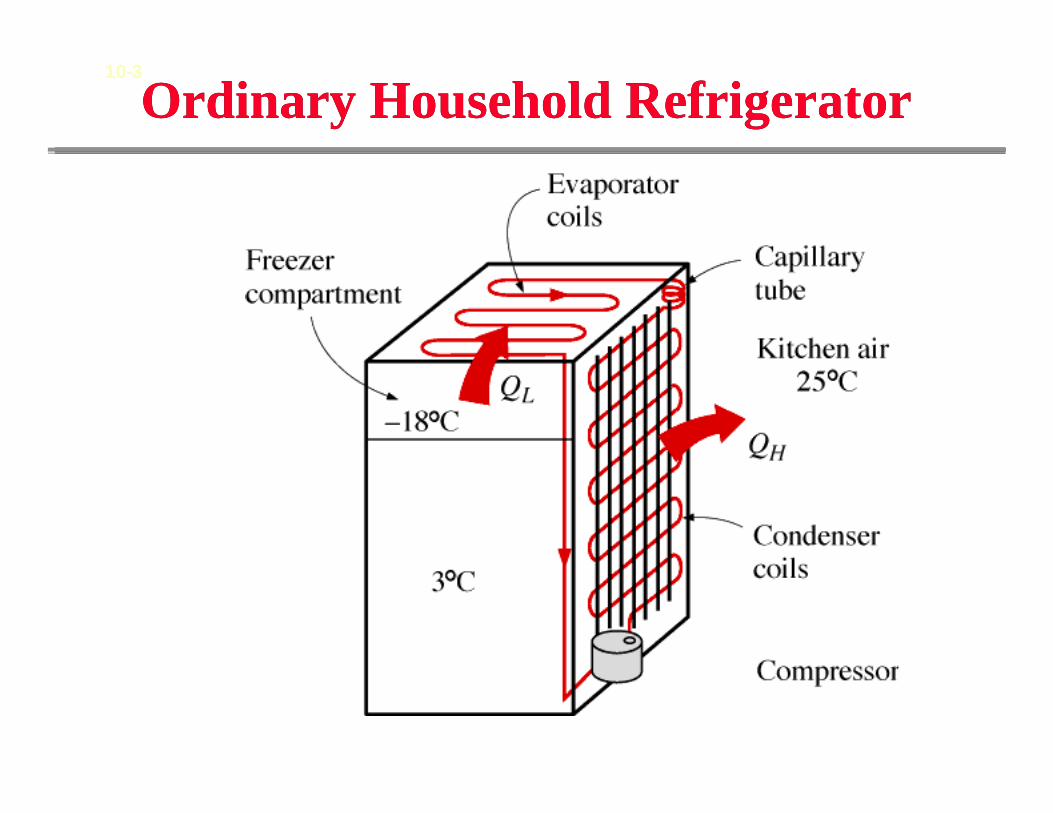
Ordinary Household RefrigeratorOrdinary Household Refrigerator
(Fig. 10-4)
10-3
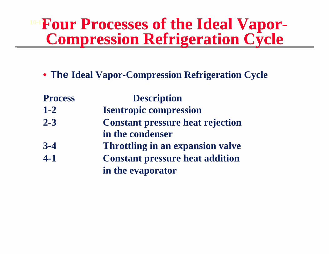
Four Processes of the Ideal Vapor-Compression Refrigeration Cycle
Four Processes of the Ideal Vapor-Compression Refrigeration Cycle
• The Ideal Vapor-Compression Refrigeration Cycle
Process Description 1-2 Isentropic compression 2-3 Constant pressure heat rejection
in the condenser3-4 Throttling in an expansion valve4-1 Constant pressure heat addition
in the evaporator
10-17
1st and 2nd Law Analysis of Ideal Vapor-Compression Refrigeration Cycle
1st and 2nd Law Analysis of Ideal Vapor-Compression Refrigeration Cycle
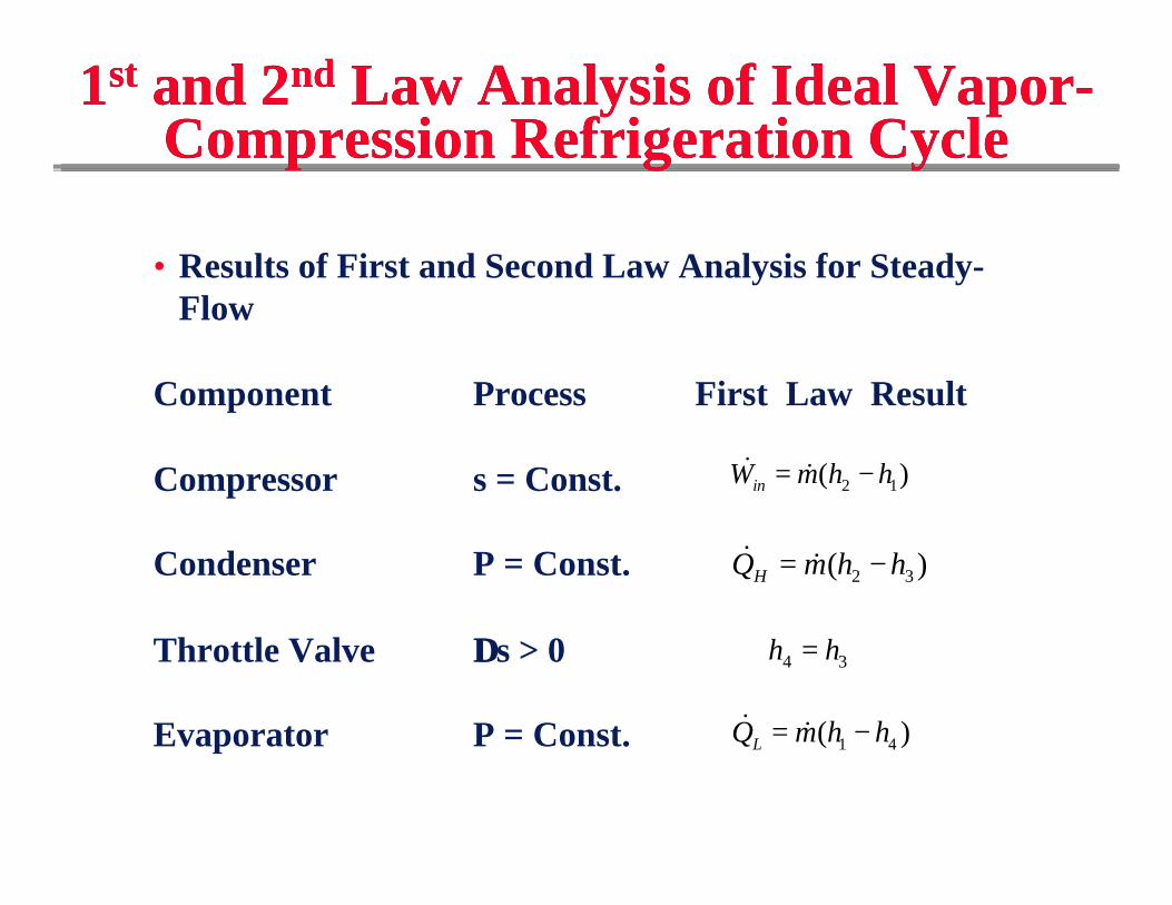
• Results of First and Second Law Analysis for Steady-Flow
Component Process First Law Result
Compressor s = Const.
Condenser P = Const.
Throttle Valve ∆∆s > 0
Evaporator P = Const.
2 1( )inW m h h= −& &
2 3( )HQ m h h= −& &
4 3h h=
1 4( )LQ m h h= −& &
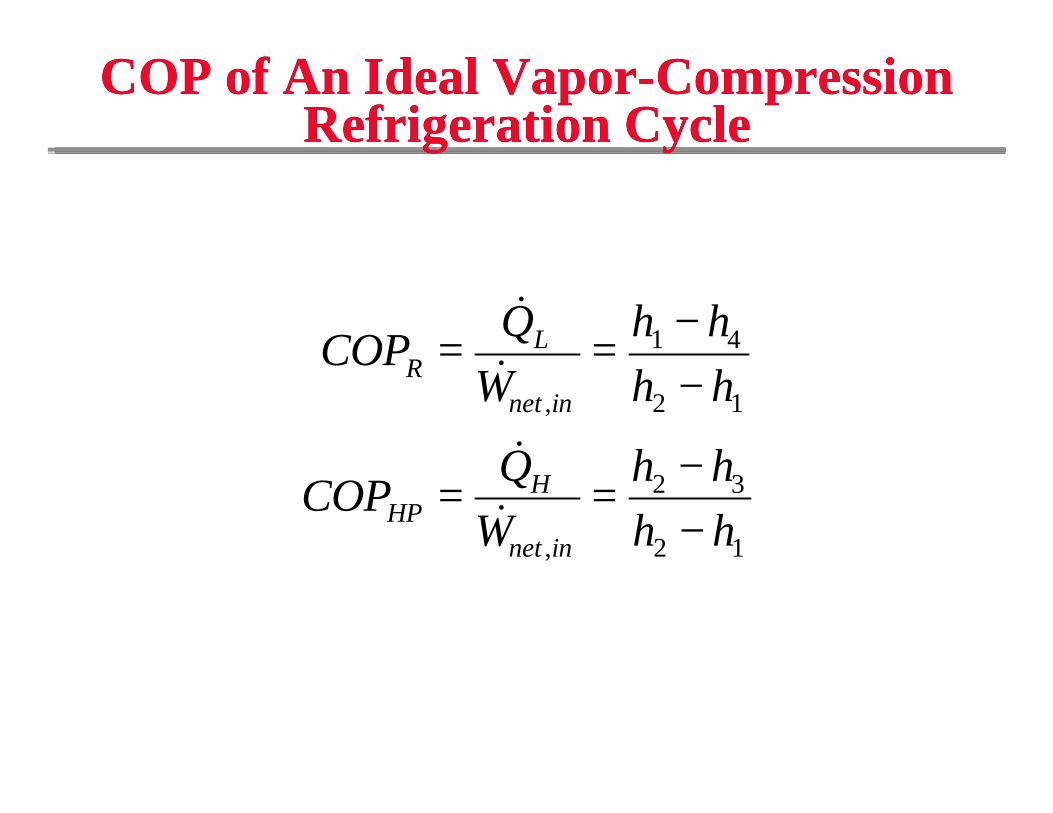
COP of An Ideal Vapor-Compression Refrigeration Cycle
COP of An Ideal Vapor-Compression Refrigeration Cycle
COPQ
Wh hh h
COPQ
Wh hh h
RL
net in
HPH
net in
= =−−
= =−−
&&&
&
,
,
1 4
2 1
2 3
2 1
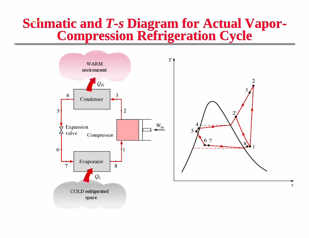
Schmatic and T-s Diagram for Actual Vapor-Compression Refrigeration Cycle
Schmatic and T-s Diagram for Actual Vapor-Compression Refrigeration Cycle
10-5
(Fig. 10-7)
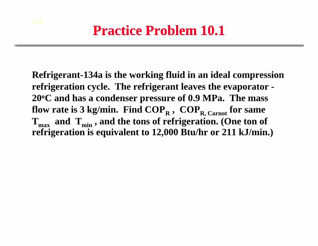
Practice Problem 10.1Practice Problem 10.110-5
Refrigerant-134a is the working fluid in an ideal compression refrigeration cycle. The refrigerant leaves the evaporator -20oC and has a condenser pressure of 0.9 MPa. The mass flow rate is 3 kg/min. Find COPR , COPR, Carnot for sameTmax and Tmin , and the tons of refrigeration. (One ton of refrigeration is equivalent to 12,000 Btu/hr or 211 kJ/min.)
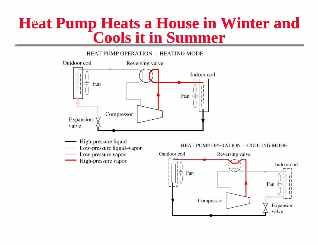
Heat Pump Heats a House in Winter and Cools it in Summer
Heat Pump Heats a House in Winter and Cools it in Summer
10-6
(Fig. 10-9)
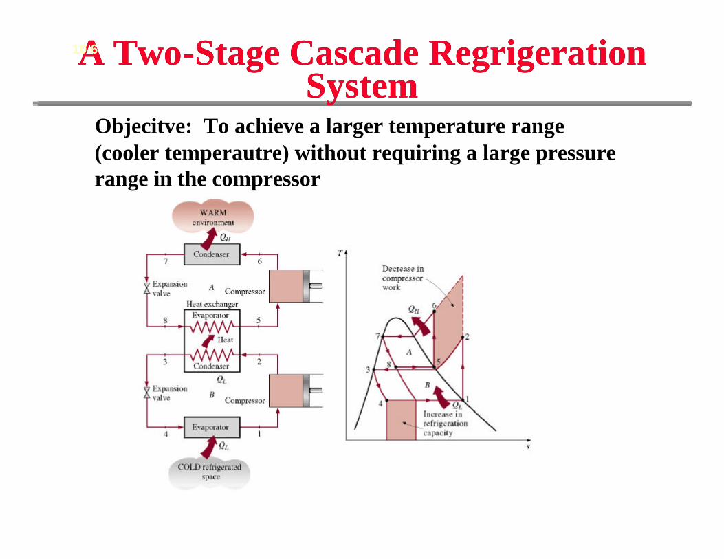
A Two-Stage Cascade RegrigerationSystem
A Two-Stage Cascade RegrigerationSystem
10-6
Objecitve: To achieve a larger temperature range (cooler temperautre) without requiring a large pressure range in the compressor
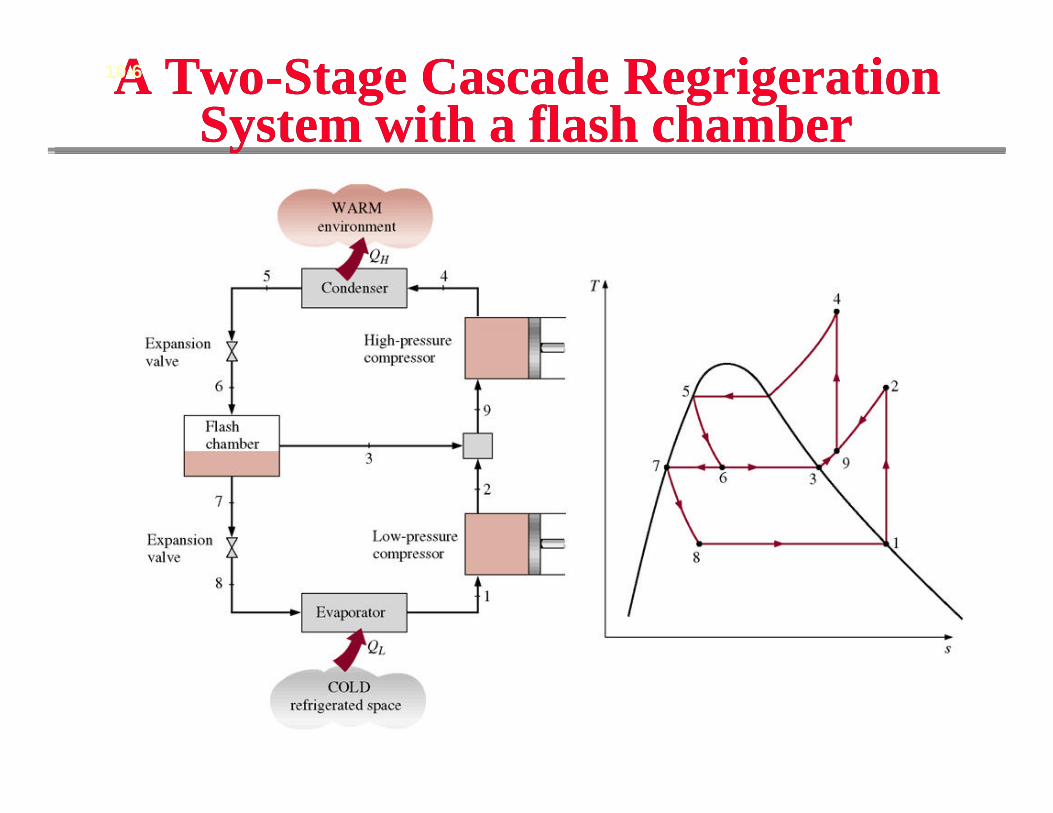
A Two-Stage Cascade RegrigerationSystem with a flash chamber
A Two-Stage Cascade RegrigerationSystem with a flash chamber
10-6
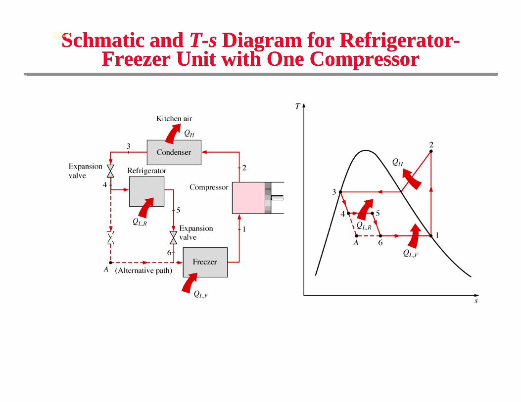
Schmatic and T-s Diagram for Refrigerator-Freezer Unit with One Compressor
Schmatic and T-s Diagram for Refrigerator-Freezer Unit with One Compressor
10-7
(Fig. 10-14)
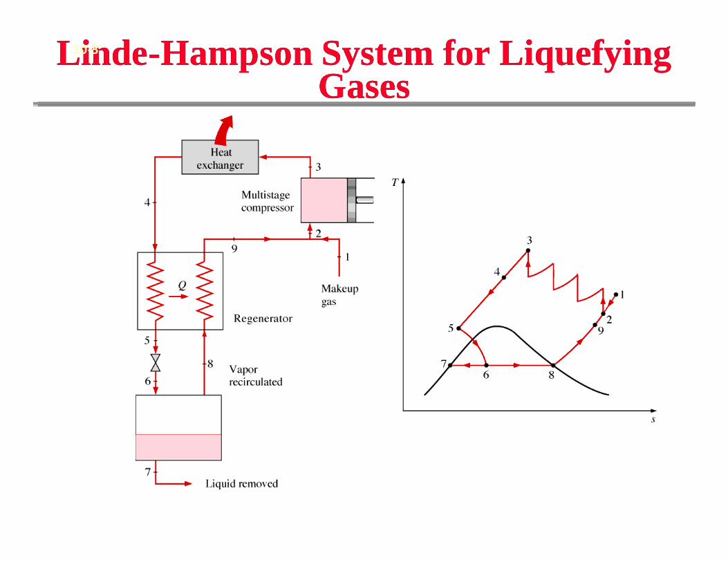
Linde-Hampson System for Liquefying Gases
Linde-Hampson System for Liquefying Gases
10-8
(Fig. 10-15)
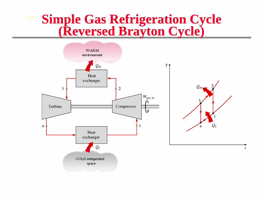
Simple Gas Refrigeration Cycle(Reversed Brayton Cycle)
Simple Gas Refrigeration Cycle(Reversed Brayton Cycle)
10-9
(Fig. 10-16)
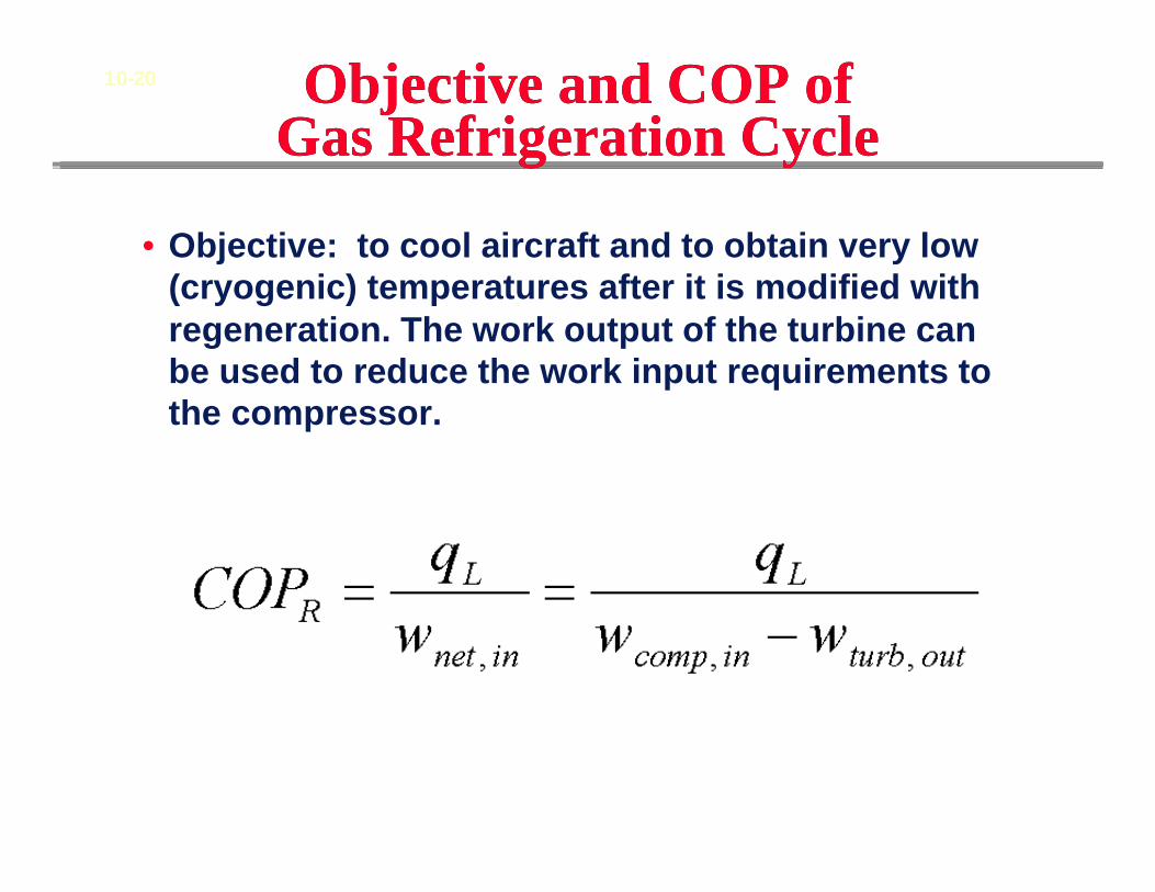
Objective and COP of Gas Refrigeration CycleObjective and COP of
Gas Refrigeration Cycle
• Objective: to cool aircraft and to obtain very low (cryogenic) temperatures after it is modified with regeneration. The work output of the turbine can be used to reduce the work input requirements to the compressor.
10-20
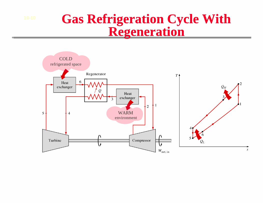
Gas Refrigeration Cycle With Regeneration
Gas Refrigeration Cycle With Regeneration
10-10
(Fig. 10-19)
COLDrefrigerated space
WARMenvironment
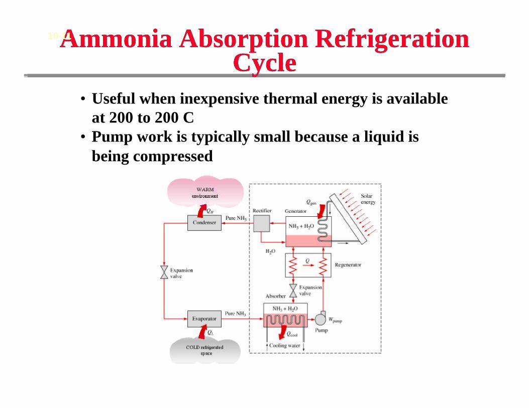
Ammonia Absorption Refrigeration Cycle
Ammonia Absorption Refrigeration Cycle
10-11
(Fig. 10-21)
• Useful when inexpensive thermal energy is available at 200 to 200 C
• Pump work is typically small because a liquid is being compressed
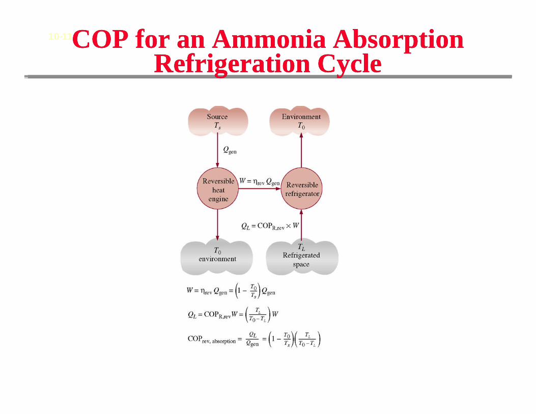
COP for an Ammonia Absorption Refrigeration Cycle
COP for an Ammonia Absorption Refrigeration Cycle
10-11