active control technologies for vrf heat pump cycle - ahpnw_multi... · air conditioning and energy...
TRANSCRIPT

Air Conditioning and Energy Solution Company
Active Control Technologies
for VRF Heat Pump Cycle
LG Electronics
Pilhyun YOON
2013.10.8
2
Contents
Active Oil Control
01 | HiPORTM Technology
02 | Real Time Oil Level Detection
03 | Real Time Oil Level Detection and Balancing
04 | Smart Oil Return
Active Refrigerant Control
01 | Ef fect of Active Refrigerant Control
02 | Active Refrigerant Control
Self Reliability
01 | Emergency Operation Function
02 | Upgrade Fault Detection and Diagnosis
Active Heat Exchanger Control
01 | Variable Heat Exchanger Circuit
02 | Continuous Heating Operation in Defrosting
03 | Cooling Operation Range Down
Superior Technologies
01 | High Ef f iciency Inverter Compressor
02 | Vapor Injection
03 | Fast Heating and Cooling
04 | Low Noise Operation
Innovative Technologies
Etc.
01 | Smart-phone Monitoring and Control
Introduction
01 | VRF System
02 | Technologies for VRF
03 | Innovative Technologies for Multi V

3
VRF System
Introduction
VRF( Variable Refrigerant Flow) System is more effective than others.
ODU IDU
Ref. Piping
VRF Heat Pump Outdoor Unit
(Cooling and Heating)Facilities
Cooling: Chiller + Cooling Tower
Heating: Boiler
52% Installation Space 100% (Mechanical Facility Room)
low Operating Cost high
Local Control Control Type Central Control
Cooling Tower
Boiler
Chiller AHU +
Air Duct
Water Piping
VRF System Chiller System

4
Technologies for VRF
Introduction
Technologies for VRF are as follows.
Piping
Outdoor Unit Indoor Units
Fan & Motor
Inverter Controller
Compressor
Inverter 2 CompsInverter 1 Comp
Heat Exchanger
Active Cycle
Controller
VRF System Basic Technologies for VRF
8~12HP 14~20HP

5
Innovative Technologies for Multi V IV
Introduction
Multi V IV has innovative active control technologies for VRF heat pump cycle.
LG Scroll Comp.
HiPOR
Active Oil Control
Active Ref. Control
Active Var. HEX
Higher Efficiency
Powerful Capacity
Easy Installation
More Reliable
Highest Comfort
World First
World First
World First
World First
World Best
Active Control Technologies Customer Values

6
HiPORTM Technology
Oil Return Capillary Bypass Effect (Conventional System)
Active Oil Control
• ODR: Oil Discharge Ratio,
• OCR: Oil Circulation Ratio
Oil Discharge Ratio Calculation of OCR
0.0
1.0
2.0
3.0
4.0
5.0
15 30 45 60 75 90 105 120 135
OD
Rnom
aliz
ed
Hz
OCR
ODR
Compressor(Variable Speed)
OilSeparator
Oil discharge ratio vs. compressor frequency.
High Pr.
Low Pr.
Designed
for Max Hz

7
HiPORTM Technology
Oil Return Capillary Bypass Effect (Conventional System)
Active Oil Control
Oil flow in compressor and oil separator.
To Condenser
Oil Separator
Capillary
Oil Separator
Capillary
Suction
Discharge
Comp.
Suction
0.80
0.85
0.90
0.95
1.00
1.05
0 0.5 1 1.5 2 2.5 3
0
1
2
3
4
5
EER
OCR
L (m)
normalized
normalized
No oil separator
EER
nom
aliz
ed
OC
Rnom
alize
d
0.80
0.85
0.90
0.95
1.00
1.05
0 0.5 1 1.5 2 2.5 3
0
1
2
3
4
5
EER
OCR
L (m)
normalized
normalized
No oil separator
EER
nom
aliz
ed
OC
Rnom
alize
dO
CR
nom
alize
d
EER and OCR at various capillary lengths. (Comp 30Hz, ARI condition)
Conventional Oil Return Demerits of Conventional System

8
HiPORTM Technology
With patent HiPORTM technology, fundamental cause of energy loss due to oil circulation has been reduced to
maximize efficiency of the compressor.
Active Oil Control
Conventional
Volume Loss
By-pass loss of high pressure refrigerant
Compressor
Oil
Separator
Accumulator
1 2 3 4
5 Loss of compressor energy
Accumulator Suction Pipe
Compressor OilSeparator
1
2
34
5
HiPORTM method (High Pressure Oil Return)
※ HiPORTM : High Pressure Oil Return
13
HiPORTM
Compressor
Oil
Separator
1 2 3
4No loss ofcompressor energy
Suction Pipe
CompressorOil
Separator
1
2
3
4

9
Real-Time Oil Level Detection
Active Oil Control
Oil recovery
Co
mp
resso
r o
il le
ve
lTime
Lower limit of
compressor oil
Real time oil
level detection
Reliability enhancement with oil level sensor
Oil level
sensor
Multi V IV applied Smart Oil Return technology, the real-time oil level detection improved compressor reliability.
Oil recovery operation carried out only during oil shortage
Fundamentally prevent risk of compressor burnt out
Co
mp
resso
r o
il le
ve
l
Oil recovery
Time
Compressor
burn out
Lack of oil
Oil recovery
Conventional
No warning during lack of oil state
Compressor burnt problem due to lack of oil status
before oil recovery operation period (8hr)

10
Real-Time Oil Level Detection, Basic Experiment
Active Oil Control
Capacitive characteristics changes greatly with oil & refrigerant mixture ratio [1]
Difference is distinguishable between 100% vapor refrigerant and 100% oil [2]
A
d
+++++++++
---------
---------
+++++++++
A
d
+++++++++
---------
---------
+++++++++
---------
+++++++++
Capacitance
Analyzer
Oil + Refrigerant
Len
gth
(L
)
Capacitance(C)
+
+
+
-
-
-
Capacitance type detector Capacitive Characteristics
100%
Oil
100%
Liquid
Refrigerant
100%
Vapor
Refrigerant
3.4
26
[1]
[2]
33% Oil +
67% Ref.
53% Oil +
47% Ref.
75% Oil +
25% Ref.
Length (L, mm)
Ca
pa
cit
an
ce
(C
,pF
)

11
Inverter Compressor
Oil Separator
Ref.+Oil
Oil
Ref.+Oil
(Low Temp., Low Pres.)
Ref.+Oil (High Temp., High Pres.)
Oil Level
Sensor
Oil Eq. Piping
Real-Time Oil Level Detection, Balancing and Return
Active Oil Control
Refrigerant Effect inside compressor
Auto Oil Balancing
Smart Oil Return
Auto Oil Balancing and Smart Oil Return
Oil LevelSensor
Oil LevelSensor
Oil Oil
Oil
Oil Balancing and Oil return algorithm with Oil level sensor
Cycle Diagram for Oil Level Detection

12
Real-Time Oil Level Detection, Smart Oil Return
Active Oil Control
Num
ber o
f oil recovery
opera
tion
Periodic oil recovery
225m10m Install pipe length
Unnecessary oil recovery operation
Conventional
VRF system is required oil recover for reliability. Multi V IV recover oil when oil level sensor detects low oil level.
It can reduce energy consumption and minimize heating operation stop time.
Periodic oil recovery is performed to secure reliability
Stop heating operation and energy consumption are
reduced due to oil recovery operation
Heatin
g C
ap
aci
ty
Time
Periodic oil recovery operation
Real Operation Test
none Heating
none Heating
none Heating
Heating Heating Heating Heating
Num
ber o
f oil recovery
opera
tion
Install pipe length
Periodic oil recovery
225m10m
Oil level
sensor
EnergyReduction
Heatin
g C
ap
aci
ty
No heating stop for 200days
Heating Heating Heating
Apply oil level sensor - Reliability up
Required oil recovery operation - Efficiency up
Oil distribution technology between compressors
Real Operation Test
Time

13
Variable Heat Exchanger Circuit
Path Number
Variable path number according the operation mode
1 43 62
Efficiency
Heating
Cooling
5
The optimization of heat exchanger's path number has improved in heating and cooling efficiency.
Active HEX Control
HeatingCooling
Path (more), Velocity (low)Path (less), Velocity (high)
Path Number
Fixed path number, low efficiency
1 43 62
Heating
Cooling
5
Efficiency
Conventional
HeatingCooling
Low efficiency for fixed refrigerant speed and path

14
Continuous Heating Operation in Defrosting
Active HEX Control
Multi V IV has split-defrosting cycle control technology for continuous heating.
Even in defrost mode, it can keep supply heating
By separating heat exchanger into 2 part, it can defrost
without stop
ON ON
Time
Heating supply
Heating
operation
Continuous
heating
Split-defrosting cycle Sequence
Lower defrost Upper defrost Lower defrost
In case of defrost mode, the unit cannot maintain heating supply
Customer have to wait until the defrost operation stop
Time
Heatingsupply
OFF OFF
Full defrost Full defrostNormal operation
Heating
operation
Stopped
heating
Conventional
Defrost cycle Sequence

15
Continuous Heating Operation in Defrosting
Active HEX Control
Some amount of hot gas is supplied for defrosting HEX without stopping heating
On
OffOn
Off
Low Side HEX Defrosting High Side HEX Defrosting
Hot Gas
Hot Gas

16
Cooling Operation Range Down
Active HEX Control
Part heat exchanger usage
-10℃
-10℃
Ambient
temp
Indoor temp14℃ 25℃
-5℃
43℃
Cooling operation area
Multi V IV continuous cooling range in low temperature is extended from -5℃ to -10℃Better solution for low cooling zone like server rooms.
Moderate low pressure by Part
Heat exchanger area
Continuous cooling operation
Full heat exchanger usage
-5℃
Ambient
temp
Indoor temp14℃ 25℃
-5℃
43℃
Cooling operation area
Conventional
Excessive low pressure by Full Heat
Exchanger area
Frequent on / off compressor operation
by low pressure protect function
17
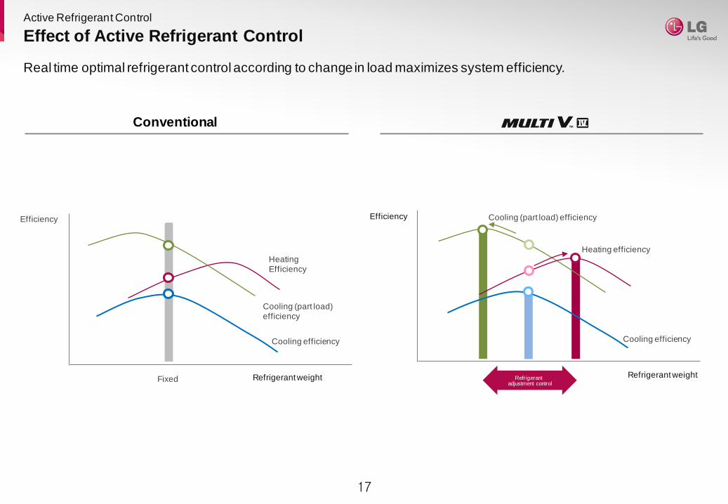
Effect of Active Refrigerant Control
Refrigerant weight Refrigerant adjustment control
Cooling efficiency
Cooling (part load) efficiency
Heating efficiency
Efficiency
Real time optimal refrigerant control according to change in load maximizes system efficiency.
Active Refrigerant Control
Fixed
Efficiency
Heating Efficiency
Cooling (part load) efficiency
Refrigerant weight
Cooling efficiency
Conventional

18
Active Refrigerant Control
(superheated steam,2-phase gas / liquid flow)
Accu
mu
lato
rR
eceiv
er Level 1
Level 3
Level 2
Receiver
Valve
Refrigerant
Real time optimal refrigerant control according to change in load maximizes system efficiency.
Active Refrigerant Control
Accu
mu
lato
r
(superheated steam,2-phase gas / liquid flow)
Refrigerant
Conventional

19
High Efficiency Inverter Compressor
Multi V IV has high efficiency all inverter scroll compressor with frequency range 15Hz~160Hz.
Superior Technologies
VI Technology applied to improve heating performance and ef f iciency
VI (Vapor Injection)
Direct oil return mechanism towards Compressor
HiPORTM (High Pressure Oil Return)
Prevent volume loss caused by oil
Required oil recovery operation by oil Level Sensor
Smart Oil Return
Minimize energy consumption
By-Pass method HiPORTM Technology
Pressure lossoccurrence
Heatin
g C
ap
aci
ty
-20℃ -15℃ -5℃ 5℃ 10℃
Base Efficiency
Heating efficiency 11%
improvement
Oil LevelSensor
No. of oil r
ecovery
opera
tion
Install pipe length
Actually required
oil recovery
Energyreduction
High pressure gas
Mediumpressure
gas
Lowpressure
gas
World best compressor speed 160Hz
Operation range (Hz)
1520
120
160
LG 3rd Generation LG 4th Generation
Rapid response capability
Compact core design (concentrated motor )
Down to 15Hz part load ef f iciency improvement
Six By-Pass Valve
1
23
4
56
20
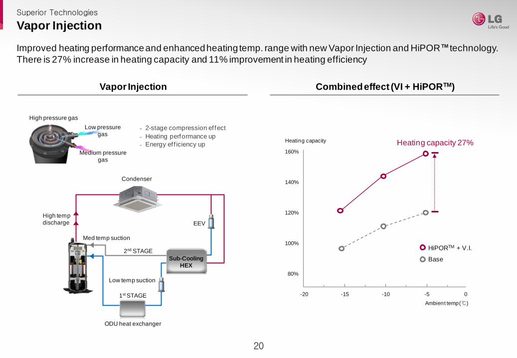
Superior Technologies
Vapor Injection
Improved heating performance and enhanced heating temp. range with new Vapor Injection and HiPOR TM technology.
There is 27% increase in heating capacity and 11% improvement in heating efficiency
High pressure gas
Medium pressuregas
Low pressuregas
‒ 2-stage compression ef fect
‒ Heating performance up
‒ Energy ef f iciency up
Condenser
EEV
High tempdischarge
2nd STAGE
ODU heat exchanger
1st STAGE
Med temp suction
Low temp suction
Sub-CoolingHEX
Vapor Injection Combined effect (VI + HiPORTM)
Heating capacity 27%
-15 -10 -5 0-20
80%
100%
120%
140%
160%
Heating capacity
Ambient temp(℃)
HiPORTM + V.I.
Base

21
Fast Heating via Advanced Inverter
time
4 min
40℃
20℃
Superior Technologies
1st stage 2nd stage
All inverter simultaneous control
World Best Level heating performance by All Inverter Compressor and Optimized Cycle Design.
Indoor unit discharge air temperature reaching time is reduced up to 63%.
Indoor Unit
Discharge air
Temperature
4 min to reach 40℃ wind
time
11 min
40℃
20℃
Multi V III
1st stage 2nd stage 3rd stage 4th stage
Compressor sequence control
Indoor Unit
Discharge air
Temperature
11 min to reach 40℃ wind

22
Fast Cooling via Advanced Inverter
World Best Level cooling performance by All Inverter Compressor and Optimized Cycle Design.
Indoor unit discharge air temperature reaching time is reduced up to 28%.
1st stage 2nd stage
All inverter simultaneous control
Indoor Unit
Discharge air
Temperature
time
5 min27℃
12℃
5 min to reach 12℃ wind
Superior Technologies
1st stage 2nd stage 3rd stage 4th stage
Compressor sequence control
Indoor Unit
Discharge air
Temperature
time
7 min27℃
12℃
7 min to reach 12℃ wind
Multi V III

23
Low Noise Operation
Superior Technologies
Operation sound level is decreased by New Fan Technology.
Low noise operation at night is possible thanks to inverter technology.
‒ Due to decrease of vortex and separation close to the blade, the air
volume is increased in 50CMM and the noise level is decreased by
4dB(A).
Cannon Fan
Sinusoidal leading edge
‒ Sinusoidal leading edge
‒ Sinusoidal chord distribution
Grooved suction surface
‒ Grooved suction surface
‒ Exfoliation of surface
Tip vortex suppressor
‒ Tip vortex suppressor
‒ Winglet technology used
on airplanes
Super cannon FanCompressor
insulation
4dB(A) 4dB(A)
New Fan Technology
Mode Start Mode End
Load
Capacity
8:00 12:00 16:00 20:00 0:00 4:00 8:00
Time
Sound
level
12:00 16:00
Night DayDay
Night Silent Operation
‒ 3 time mode : 9 hr, 10.5 hr, 12 hr
‒ 3 step noise level : 55 dB(A), 52 dB(A), 49dB(A)
3 Time Mode and 3 Step Noise Level

24
Emergency Operation Function
Self Reliability
Emergency Operation Function minimizes the inconvenience that may occur in an emergency and makes servicing
very convenient and easy.
Malfunction
Back-up operationONOFFMalfunction
Back-up
ON
ONOFFOFFMalfunction
Automatic emergencyback up operation
Back-up Operation Auto Refrigerant Collection Operation
PUMP DOWN
‒ in case indoor fail, ref rigerant f rom indoor unit and pipe is collected
to outdoor unit.
PUMP OUT
‒ in case outdoor fail, ref rigerant f rom outdoor unit pipe
is pumped to indoor unit and pipe.
Automatic emergency back up function operates the alternate
compressor during compressor failure.
When an outdoor or indoor unit malfunctions, this function
automatically collects its refrigerant before servicing.

25
Upgraded Fault Detection and Diagnosis
In Multi V IV has improved black box function, auto refrigerant charging and refrigerant recovery operation
the reliability and ease of maintenance.
Failure history storage(black box function) Automatic refrigerant leakage and sensor check
‒ 3 years operation record data can be saved with SD memory card ‒ After product installation, ref rigerant leakage is checked and then
ref rigerant charge is judged through start up operation
SD memory module (Option)
Main PCB black box function
Automatic refrigerant charge technology Auto refrigerant charge check
‒ There is service port on outdoor unit, ref rigerant can be charged
even during winter
‒ Refrigerant calculation is possible even in case of minor ref rigerant
leakage
‒ Prevent ref rigerant leakage due to sensor failure or
compressor burnout.
FDD (algorithm)
Ref ChargingLED display
Refrigerantleakage
Refrigerantleakage
※ Incase of Outdoor Unit 20HP, Indoor Unit 4ea
Self Reliability

26
Smartphone Monitoring and Control
Real time monitoring and management of commissioning, maintenance of central controller site are possible through
smartphone and remote control.
indoor
485 Internetbrowser
Remote monitoring
Bluetooth Smartphone based LGMV(for service)
Admin’sApp.
LG SAC Control App.
Central controller site
Controller(ACP)
485
Installation Site
Cycle monitoring and control
Group control
Wi-Fi
All Model Single CAC
Smartphone and
Remote control
[Smartphone]
[Pad]
[Notebook]
Manager
Smartphone Control Smartphone Application
Etc.

27
www.lgeaircon.com
Copyright © 2013 LG Electronics. All Rights Reserved.