breaking the cycle of pump repairs
TRANSCRIPT

1
BREAKING THE CYCLE OF PUMP REPAIRS
Heinz P. Bloch, P.E. Process Machinery Consulting
Westminster, CO 80031
Heinz P. Bloch, P.E., is an ASME Life Fellow. He was one of the original Pump Advisory board members and is the author or co-author of 18 full-length books and over 500 papers on lubri-cation, failure avoidance, and equipment reliability. Some of his works have been translated into 5 languages. He has 7 machinery-related patents to his credit.
ABSTRACT Achieving lowest possible life cycle cost (LCC) and value-optimized mean-times-between-repairs (MTBRs) are the undisputed goals of thoughtful pump users. Achieving these goals requires concentrating not only on pump hydraulics, but also on improving pump power end (drive end) reliability. Because bearing protection and lubricant delivery have not kept pace with the demand for least-risk configurations, a few reliability-focused Best-of-Class performers have implemented their own field modifications and upgrades which eliminated many previously unexplained lube and bearing-related events. They thereby avoid both random and repeat-failures in API-compliant process pumps. With progressive pump users now often enjoying pump MTBRs four times greater than their competitors, there is increasing demand for better understanding a number of “elusive” and seemingly overlooked issues. A five-decade pump failure avoidance veteran and machinery improvement professional explains details. This common sense tutorial shows and emphasizes facts not widely known or publicized. INTRODUCTION Of the numerous process centrifugal pumps undergoing repair right this very minute, an estimated 90% have failed randomly before. Some have run just fine until the very first repair two or three years after startup, and were never quite the same since after the first repair. Other pumps failed frequently or randomly--perhaps once a year--from the time they were originally commissioned. That brings up such questions as: Could it be we don’t really know why many process pumps are failing? Could it be we just don’t give pumps the attention they deserve? Is it because everybody’s priorities are elsewhere? Or are there perhaps elusive failure reasons, i.e., factors overlooked by all parties?
Fortunately, improvement is both possible and cost-justified. Allowing repeat failures on process pumps rarely makes economic sense. Simple benefit-to-cost or life cycle analyses will easily demonstrate that the pursuit of remedial action greatly benefits users. Examining the cost of failures One way of exploring the value of extending pump mean-time-between-failures (MTBF) is to examine the likely savings if we could improve the MTBF from presently 4.5 years to a projected 5.5 years. Say, a facility has 1,000 pumps; that’s 1,000/4.5 = 222 repairs before and 1000/5.5 = 182 repairs after understanding and solving the problem. Avoiding 40 repairs at $ 6,000 each is actually a very low estimate, but would be worth $240,000. Avoiding repairs frees up manpower for other tasks: At 20 man-hours times 40 incidents times $100 per hour, reassigning these professionals to other repair avoidance tasks would be worth at least $80,000. There is also one ~$3,000,000 ($3M) fire per 1,000 pump failures. An engineer at a U.S. Gulf plant thought it might more likely be 1 fire per 1,000 pump failures, then out of 10 fires he figures seven are less than $50K, two are $50-500K and 1 is >$500k. He asked the author to provide the source of the $3M/ 1,000 failures figure. Suffice it to say the numbers are based on 52 years of experience and two recent updates. Data obtained in 2012 from a refinery in the Chicago area considered the $3,000,000 low, whereas a facility in one of the mid-western states of the U.S., in 2009, thought it was spot-on. So, the numbers are reasonably accurate. Take into account that cost and details of catastrophic incidents are often closely guarded secrets. Virtually all consulting done today by qualified independent professional engineers is linked to a legally binding non-disclosure agreement. The client is often compelled to file reports with local and federal regulatory agencies. These reports might differ from the findings of consulting engineers who understand the true root causes of failures, or whose sense of priorities is tuned to higher standards. Diverging statements or findings might feed a bureaucratic machine that will busy itself with issues of this type. However, these estimates for the value of fire damage restoration cost are in line with experience: Avoiding 40 repairs would be worth 40/1,000 x $ 3,000,000 = $120,000. Together, the three items ($240k, $80k and $120k) add up to $440,000.
Proceedings of the Twenty-Ninth International Pump Users Symposium October 1-3, 2013, Houston, Texas

2
Although $ 6,000 was used for repair cost avoidance calculations earlier, an average API pump repair at a Texas refinery costs slightly over $10,200; a refinery in Mississippi reported $11,000. If the incremental cost of upgrading during the next repair adds $2,000 to the repair bill and avoids even a single failure every 3 or 4 years over the 30-year total life of a pump, the payback will have been quite substantial. It would be reasonable to assume 8 avoided repairs at $6,000 give payback of 48k/2k = 24:1. The quoted repair cost numbers of close to $11,000 reflect what needs to be considered in a pump repair cost calculation: Direct labor, direct materials, employee benefits at roughly 50% of direct labor, refinery administration and services costs at close to 10% of direct labor, mechanical-technical service personnel overhead costs amounting to ~115% of direct labor, and materials procurement costs from 7% to 8% of materials outlay (Bloch and Budris, 2010; Ref. 1). Disregarding the true cost of failures or repairs is likely to deprive some users of seeing the true benefit-to-cost ratio associated with pump upgrades. We could examine other ways to calculate as well. It would be reasonable to assume that implementing a component upgrade (generally the elimination of a weak link) extends pump uptime by 10%. Implementing 5 upgrade items yields 1.1^5 = 1.61--- a 61% mean-time-between-repair (MTBR) increase. Or, say, we gave up 10% each by not implementing 6 reasonable improvement items. In that instance, 0.9^6= 0.53, meaning that the MTBR is only 53% of what it might otherwise be. That might explain industry’s widely diverging MTBRs. The MTBR-gap is quite conservatively assumed to range from 3.6 years to 9.0 years in U.S. oil refineries and, as of 2013, no well-informed pump professional has disagreed with this range of MTBR numbers. Pumps have a defined operating range
Figure 1: Barringer-Nelson curves show reliability impact of operation away from BEP (Courtesy of Paul Barringer, www.barringer1.com) The onset of pump problems is not the same for different pumps, or different services. Attempts to identify best practices are to be commended. Both Paul Barringer and Ed Nelson contributed to Figure 1, the typical HQ curve. They plotted eight traditional non-BEP problem areas on that curve. The plot supports the notion that pump reliability can approach zero as one operates farther away from the best efficiency point, or BEP.
HIGHLIGHT 1: Stay well inside the defined operating range. Safe operating margins are the key to failure avoidance The implications of Figure 1 are summarized in Highlight 1. Just because pumps are able to run at lower than BEP flows does not mean that it’s good to operate there. Compare it to a vehicle able to go 12 mph in 6th gear, or 47 mph in 1st gear. It can be done, but will likely prove costly if done for very long. Pioneering efforts to define minimum allowable flows can be traced back decades and attention is drawn to the sketch, Figure 2, originally published by Irving Taylor in 1977 (Taylor, 1977; Ref. 2). His work is worth mentioning because he approximated in a single illustration what others have tried to convey in complex words and mathematical formulas. Taylor deserves much credit because he kept the average user in mind.
Figure 2: Pump manufacturers usually plot only the NPSHr trend associated with the lowermost curve. At that time a head drop or pressure fluctuation of 3% exists at BEP (“Best Efficiency Point”) flow (Taylor, 1977; Ref. 1). Irving Taylor’s trend curves of probable NPSHr for minimum recirculation and zero cavitation-erosion in water, Figure 2, are sufficiently accurate to warrant the attention of reliability professionals who wish to work within safe margins. Hundreds of references exist on the subjects of cavitation and internal recirculation; stable pump operation is always the central aim. However, the actual NPSHr needed for zero damage to impellers and other pump components may be many times the number published in the manufacturer’s literature. The manufacturers’ NPSHr plots (lowermost curve in Figure 2) are commonly based on observing a 3% drop in discharge head or pressure. Taylor’s plot places the Q = 100% intersect at an NPSHr = 100% of the manufacturer’s stated value. Unfortunately, whenever this 3% fluctuation occurs, a measure of damage may already be in progress. It is prudent to assume a more realistic NPSHr and to provide an NPSHa in excess of this likely NPSHr. Doing so builds a certain margin of safety into the pump and reduces the risk of catastrophic failure events. There are hydrocarbon services where an NPSHa surplus of just 1 ft over NPSHr will be sufficient to avoid cavitation. However, there are also services, such as Carbamate, where a 25 ft surplus is not nearly enough. Therefore, Taylor’s trend curves are considered general approximations for prudent users. He indicated that users should enlist the help of competent pump manufacturers and experienced design contractors to

3
agree on NPSH multipliers or bracket the right NPSH margins for a particular liquid or pumping service. Again, Irving Taylor gave a demarcation line between low and high suction specific speeds (Nss) at somewhere between 8,000 and 12,000. His data are supported by surveys taken after 1977 at Amoco (Texas City) and other locations; most pointed to 8,500 or 9,000 as numbers that deserve our attention. If pumps with Nss numbers higher than ~9,000 and specific speeds (Ns) above 3,500 are being operated at flow rates much higher or lower than BEP (Best Efficiency Point), the life expectancy or repair-free operating time of these pumps will be reduced. Whether these reductions will amount to 10% off normal or 60% off normal is the subject of much debate and requires reviews on a pump-specific basis. While no rigorous Nss value exists, cautious reliability professionals observe safe margins. Many users choose Nss = 9,000 as the limit for flows away from BEP. There are, however, some low Ns-pumps (including certain high-speed Sundyne designs) that will operate quite well with Nss-values higher than 9,000. But these are special cases and a close pump- user-to-pump-manufacturer relationship is needed to shed light on long term experience. Getting into mechanical issues The vulnerability of operating process pumps in parallel is not always appreciated by pump purchasers, although API-610 advises against parallel operation for pumps with relatively flat performance curves. Reasonable, yet general, specifications require a 10% minimum head rise from BEP to shut-off. There are problems with short elbows near the suction nozzle of certain pumps and flow stratification and friction losses are sometimes overlooked. Some sources advocate a minimum of 5; others advocate a 10-diameters equivalent of straight pipe run at the pump suction. Together, pump parallel operation and piping issues make up our Highlight 2. HIGHLIGHT 2: Avoid parallel operation unless head rise from BEP to shutoff is 10%. Beware of close elbows and wrong elbow orientation in double-flow pumps. Install eccentric pipe reducers with the correct orientation The tie-in between the lack of conservatism in piping and issues of less-than-adequate pump reliability is tenuous; still, the multipoint trouble illustration in Figure 1 is of interest here. Suffice it to say that tight-radius elbows and incorrect pipe reducer orientation can quickly wreck certain pump configurations (Karassik et al, 1985; Ref. 3). Neglecting piping issues can be a costly mistake, but this is not a piping tutorial. Pulling piping into place at a pump nozzle can cause edge-loading of the pump’s bearings, which will lead to premature bearing failures. Did soil settlement under pipe supports play a role in misalignment? Concrete driveway sections often misalign a few scant years after construction, so why would pipe supports still be vertical decades after they were first installed? Have they been checked during planned shutdowns? By listing Highlight 2 the author wants to make users aware of
hydraulic and flow separation issues. The flow velocity at the small-radius wall of an elbow will differ from that at the large-radius wall. And again, because these facts are generally well known and many symposia have been devoted to them, our discussion is redirected to pump mechanical or drive end (i.e., power end) issues. Our main topic is failure avoidance in the pump’s drive end and the tutorial concentrates on elusive reasons why many pumps fail repeatedly. Deviations from best available technology User plants will usually get away with one or two small deviations from best available technology. But when three or more deviations occur, failure risks usually increase exponentially. That said there are a number of reasons why a few well-versed reliability engineers are reluctant to accept pumps that incorporate the drive end shown in Figure 3 (Bloch, 2011; Ref. 4). The short overview of reasons is that reliability-focused pros take seriously their obligation Figure 3: A bearing housing with several potentially costly vulnerabilities to consider the actual, lifetime-related and not just short-term, cost of ownership. Specialists realize that the bearings in Figure 3 will work initially and then fail prematurely. The housing is shown here exactly as originally provided, including its several risk increasing features. Allowing these features to exist will sooner or later hurt the profitability of users and vendors alike. All are related to lube application and process pump users should pay very close attention to these and other lube application matters. These matters point to Highlight 3, followed by a description of vulnerabilities. HIGHLIGHT 3: Oversights can affect the adequacy of lube application Upon examining Figure 3 a careful viewer can be certain of five facts:
• In Figure 3, oil rings are used to lift oil from the sump into the bearings. These oil rings tend to skip and jump at progressively higher shaft surface speeds, or if not perfectly concentric, or if not operating in perfectly horizontal shaft systems.
4
• As the pump is transported from shop to field, an oil ring can become dislodged and get caught between the shaft periphery and the tip of the long limiter screw.
• The back-to-back oriented thrust bearings of Figure 3 are not located in a cartridge. This limits flinger disc dimensions (if they were to be retrofitted) to no more than the housing bore diameter.
• Bearing housing protector seals are missing from the picture in Figure 3. Once added, bearing protector seals in this housing will change the flow of venting air.
• Although the bottom of the housing bore (at the radial bearing) shows the needed oil return passage, the same type of oil return or pressure equalizing passage seems to have been left out near the 6 o’clock position of the thrust bearing. A small pool of oil can accumulate behind the thrust bearing and this oil will probably overheat. Carbon debris and sludge tend to locate there.
• No particular constant level lubricator is shown in Figure 3 and there is uncertainty as to the type or style of constant level lubricator that will be provided. Unless specified, OEMs rarely supply the best available constant level lubricator.
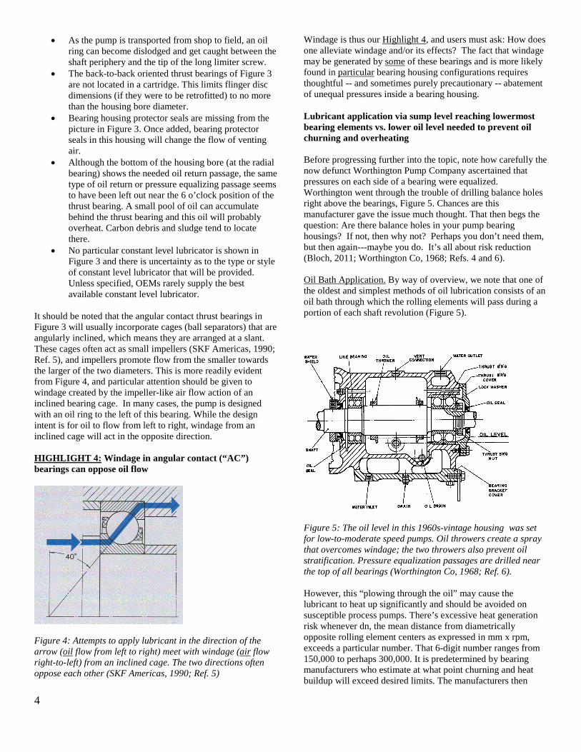
It should be noted that the angular contact thrust bearings in Figure 3 will usually incorporate cages (ball separators) that are angularly inclined, which means they are arranged at a slant. These cages often act as small impellers (SKF Americas, 1990; Ref. 5), and impellers promote flow from the smaller towards the larger of the two diameters. This is more readily evident from Figure 4, and particular attention should be given to windage created by the impeller-like air flow action of an inclined bearing cage. In many cases, the pump is designed with an oil ring to the left of this bearing. While the design intent is for oil to flow from left to right, windage from an inclined cage will act in the opposite direction. HIGHLIGHT 4: Windage in angular contact (“AC”) bearings can oppose oil flow
Figure 4: Attempts to apply lubricant in the direction of the arrow (oil flow from left to right) meet with windage (air flow right-to-left) from an inclined cage. The two directions often oppose each other (SKF Americas, 1990; Ref. 5)
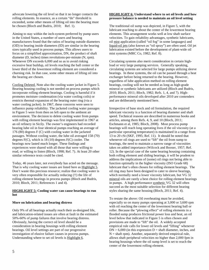
Windage is thus our Highlight 4, and users must ask: How does one alleviate windage and/or its effects? The fact that windage may be generated by some of these bearings and is more likely found in particular bearing housing configurations requires thoughtful -- and sometimes purely precautionary -- abatement of unequal pressures inside a bearing housing. Lubricant application via sump level reaching lowermost bearing elements vs. lower oil level needed to prevent oil churning and overheating Before progressing further into the topic, note how carefully the now defunct Worthington Pump Company ascertained that pressures on each side of a bearing were equalized. Worthington went through the trouble of drilling balance holes right above the bearings, Figure 5. Chances are this manufacturer gave the issue much thought. That then begs the question: Are there balance holes in your pump bearing housings? If not, then why not? Perhaps you don’t need them, but then again---maybe you do. It’s all about risk reduction (Bloch, 2011; Worthington Co, 1968; Refs. 4 and 6). Oil Bath Application. By way of overview, we note that one of the oldest and simplest methods of oil lubrication consists of an oil bath through which the rolling elements will pass during a portion of each shaft revolution (Figure 5).
Figure 5: The oil level in this 1960s-vintage housing was set for low-to-moderate speed pumps. Oil throwers create a spray that overcomes windage; the two throwers also prevent oil stratification. Pressure equalization passages are drilled near the top of all bearings (Worthington Co, 1968; Ref. 6). However, this “plowing through the oil” may cause the lubricant to heat up significantly and should be avoided on susceptible process pumps. There’s excessive heat generation risk whenever dn, the mean distance from diametrically opposite rolling element centers as expressed in mm x rpm, exceeds a particular number. That 6-digit number ranges from 150,000 to perhaps 300,000. It is predetermined by bearing manufacturers who estimate at what point churning and heat buildup will exceed desired limits. The manufacturers then
5
advocate lowering the oil level so that it no longer contacts the rolling elements. In essence, as a certain “dn” threshold is exceeded, some other means of lifting oil into the bearing must be chosen (Bloch and Budris, 2010; Ref. 1). Aiming to stay within the inch-system preferred by pump users in the United States, a number of users and bearing manufacturers found that the ratios of bearing outside diameters (OD) to bearing inside diameters (ID) are similar in the bearing sizes typically used in process pumps. This allows users to focus on a simplified approximation, DN, the product of shaft diameter (D, inches) times revolutions-per-minute (N, rpm). Whenever DN exceeds 6,000 and so as to avoid risking excessive heat buildup, oil levels reaching the ball center or the lower third of the lowermost rolling element are considered a churning risk. In that case, some other means of lifting oil into the bearing are chosen. Cooling Deleted. Note also the cooling water jacket in Figure 5. Bearing housing cooling is not needed on process pumps which incorporate rolling element bearings. Cooling is harmful if it promotes moisture condensation (via water cooling coils) or restricts thermal expansion of the bearing outer ring (via a water cooling jacket). In 1967, these concerns were seen to influence pump reliability. The jacketed cooling water passages in Figure 5 were from then on left open to the ambient air environment. The decision to delete cooling water from pumps with rolling element bearings was first implemented in 1967 at an oil refinery in Sicily. The owner’s engineers had recorded bearing lube oil in four identical pumps reaching an average of 176 (80) degrees F (C) with cooling water in the jacketed passages. Without cooling water, the lube oil averaged 158 (70) degrees F(C), which is 18 (10) degrees F(C) cooler. The bearings now lasted much longer. These findings and experiences were shared with all those that were willing to read, or willing to listen (Bloch, 1998; Ref. 7). At least 20 other similar reference texts could be cited. Today, 46 years later, not everybody has acted on the message. That is why cooling water issues are listed here as Highlight 5. Don’t waste this precious resource; realize that cooling water is very often responsible for actually reducing (!!) the life of rolling element bearings in process pumps (Bloch and Budris, 2010; Bloch, 2011; References 1 and 4). HIGHLIGHT 5: Cooling water can cause bearings to run hot More on lubrication and bearing distress Only 9% of all bearings actually reach their as-designed life, and lubrication-related issues are often at fault in the estimated 50%-60% of pump failures that involve bearing distress. Obviously, having the correct oil level should be a consideration in bearing housings with rolling element bearings. Oil level settings are part of our progressive investigation of elusive failure causes in process pumps. Understanding where to set oil levels is Highlight 6.
HIGHLIGHT 6: Understand where to set oil levels and how pressure balance is needed to maintain an oil level setting The traditional oil sump was depicted, in Figure 5, with the lubricant reaching to about the center of the lowermost bearing elements. This arrangement works well at low shaft surface velocities. To gain reliability advantages, synthetic lubricants, oil mist application (called “oil fog” in some languages) and liquid-oil jets (also known as “oil spray”) are often used. Oil jet lubrication existed before the development of plant-wide oil mist systems (MRC Co, 1982; Ref. 8). Circulating systems also merit consideration in certain high-load or very large pumping services. Generally speaking, circulating systems are selected for large pumps utilizing sleeve bearings. In these systems, the oil can be passed through a heat exchanger before being returned to the bearing. However, regardless of lube application method on rolling element bearings, cooling will not be needed as long as high-grade mineral or synthetic lubricants are utilized (Bloch and Budris, 2010; Bloch, 2011; Bloch, 1982; Refs. 1, 4, and 7). High-performance mineral oils developed after 2010 are contenders and are deliberately mentioned here. Irrespective of base stock and oil formulation, the required lubricant viscosity is a function of bearing diameter and shaft speed. Technical reasons are described in numerous books and articles, among them Refs. 4, 9, and 10 (Bloch, 2011; Eschmann et al, 1985; Bloch, 2008). Most process pump bearings will reach long operating lives if the oil viscosity (at a particular operating temperature) is maintained in a range from 13 to 20 cSt (SKF, 1995; Ref. 11). It should be noted that whenever oil rings are used to “lift” the oil from sump to bearings, the need to maintain a narrow range of viscosities takes on added importance (Wilcock and Booser, 1957; Ref. 12). In the special case of the same bearing housing containing both rolling element and sliding bearings, it will be prudent to address the implications of (some) oil rings not being able to function optimally in the higher viscosity (ISO Grade 68) lubricant that’s often chosen for rolling element bearings. The oil ring may have been designed to cater to sleeve bearings, which normally need a lower viscosity lubricant, but VG 32 mineral oils are rarely a best choice for rolling element bearings in pumps. A high performance synthetic VG 32 will often succeed as the most suitable selection for different bearing styles sharing the same housing (Bloch, 2011; Ref. 4). To restate the above: Oil overheating must be avoided, especially so on many pumps operating at 3,000 or 3,600 rpm with oil reaching the center of the lowermost bearing ball or roller. Because the “plowing effect” of rolling elements in a flooded sump produces frictional power loss and heat, an oil level below that indicated in Figure 5 is often chosen and provisions are made to “lift” the oil. A widely accepted empirical rule calls for lower oil levels and “lifting” whenever DN > 6,000 (in this expression D = shaft diameter, inches, and N = shaft rpm). Another, separately derived empirical rule, allows shaft peripheral velocities no higher than 2,000 fpm in bearing housings where the oil sump level is set to reach the center of the lowermost rolling element.

6
Windage. In oil mist lubrication systems it is generally understood that with shaft surface velocities in excess of 2,000 fpm (~10 m/s), windage effects are opposing the flow of oil mist. As this is being observed, uninformed or baffled oil mist users have, in some cases, reverted back to conventional oil lubrication. In sharp contrast, reliability-focused users have, for many decades, installed directed oil mist reclassifiers to overcome windage action at > 2,000 fpm (~10 m/s). The mist dispensing opening in these reclassifiers is located ~0.2-0.4 inches (~5-10 mm) from the rolling elements. Thousands of these have been supplied and used with total success. This information is available from dozens of texts and articles (including Bloch, 2009; Bloch, 1987; Bloch and Shamim, 1998; Refs. 10, 13, and 14). Lifting the Oil. Again, once the shaft peripheral velocity exceeds 2,000 fpm (~10 m/s), the oil level should be no higher than a horizontal line tangent to the lowermost bearing periphery. This means there should be no contacting of the oil level with any part of a rolling element and oil “lifting” is needed. Assume that Figures 3 and 6 represent situations where DN > 6,000. Therefore, and because initial cost was to be minimized, either oil rings (Figure 3) or shaft-mounted flinger discs (Figure 6) were chosen. Both arrangements are available to lift the oil, or to somehow get the oil into the bearing by creating a random spray. Shaft-mounted flinger discs (Figure 6) are well represented in many European-made pumps. If properly designed, their operating shaft peripheral speed range exceeds that of oil rings.
Figure 6: A bearing housing with a cartridge containing the thrust bearing set. The bearing housing bore is slightly larger than the diameter of the steel flinger disc, making assembly possible. The drawing does not show the required oil return passage at the 6 o’clock bearing positions (Bloch, 2011; SKF Americas, 1995; Refs. 4 and 11).
Two different DN-rules explained When determining oil level settings, either of two empirical rules could be applied. To illustrate Rule (1): A 2-inch bore bearing at 3,600 rpm, with its DN value of 7,200, would operate in the risky or ring instability-prone zone > 6,000. Equipment with a 3-inch bore bearing operating at 1,800 rpm (DN = 5,400) might use oil rings without undue risk of ring instability. In another example, using Rule (2): A 3-inch (~75 mm) diameter bearing bore at 3,600 rpm would operate with a shaft peripheral velocity of (3.14D/12)(3,600) = 2,827 fpm (~14.4 m/s), which would disqualify oil rings from being considered for highly reliable pumps. The fact that a pump manufacturer can point to satisfactory test stand experience at higher peripheral velocities is readily acknowledged, but field situations represent the “real world” where shaft horizontality and oil viscosity, depth of oil ring immersion, bore finish and out-of-roundness are rarely perfect. We can thus opt for using either the DN < 6,000 or the Surface Velocity < 2,000 fpm (~10 m/s), or the lesser of these two “real-world” rules-of-thumb. Either way, the vendor’s test stand experience is of academic interest at best. Pump manufacturers test under near-ideal conditions of shaft horizontality, oil ring concentricity and immersion, oil level and lubricant viscosity. As users we might ask ourselves how often we have seen non-round oil rings, or rings that have shaft radius wear marks (from shaft fillet radii) on one side of the ring. If the answer is “never,” perhaps another look will be warranted. For the reliability-focused, the wide-ranging field experience that led to these two rules-of-thumb will govern over all else. Cartridge Mounting. The cartridge approach for mounting thrust bearings is shown in Figure 6. It has been in use for an estimated 50 or 60 years on thousands of open-impeller ANSI pumps because it facilitates impeller position adjustment in the axial direction. The same cartridge approach may be needed to dimensionally accommodate flinger discs (Figure 6) instead of vulnerable oil rings (Figure 7). Of course, cartridge-mounted bearings are a cost-adder and users may hear claims that the benefit-to-cost-ratio will not justify upgrading to cartridges. However, with the average API pump repair costing slightly over $10,200 at a Texas oil refinery and $11,000 at an oil refinery in Mississippi, we might be surprised at the payback multiplier. Even a single avoided failure over the 30-year total life of a pump will probably pay for it many times over. The trouble with oil rings and constant level lubricators Issues with oil rings are found in many scholarly works (Baudry and Tichvinsky, 1937; also Refs. 15 through 18). On a website post in September 2012, the Malaysian Government’s OSHA agency alerted readers to catastrophic failures brought on by oil rings (www.dosh.gov.my, 2012; Ref. 19). All of these sources observed problems with oil rings, although an industry source opined (in 2011) that “ring lubrication is an accepted practice and it would take user consensus to damn it.” Of course, history shows us that innovations are rarely driven by consensus. If they were, the Wright Brothers would have

7
worked on repeat pump and bicycle repairs instead of developing a powered flying machine. Meanwhile, keep in mind that this tutorial is for the reliability-focused. Nothing will convince those who accept without questioning dozens of repeat failures of centrifugal pumps at their plants. Many illustrations of failed oil rings are available. Studies, observations and measurements have shown the field reliability of oil rings in process pumps out of harmony with industry’s quest for higher reliability and availability. Work described in Refs. 12 and 15 (Wilcock and Booser, 1957) recommends oil ring concentricity within 0.002 inches (0.05 mm). However, in 2009, shop measurements were performed by the author at a pump user’s site in Texas. The oil rings measured in 2009 exceeded the 0.002-inch (0.05 mm) allowable out-of-roundness tolerances by a factor of 30 (Bloch, 2011; Ref. 20). Experience shows that oil rings are rarely the most dependable or least-risk means of lubricant application. They tend to skip around and even abrade (Figure 7) unless the shaft system is truly horizontal, unless ring immersion in the lubricant is just right, and unless ring eccentricity, surface finish, and oil viscosity are within tolerance. Taken together, these parameters are not usually found within close limits in actual operating plants and Highlight 7 is thus of interest. HIGHLIGHT 7: Flinger discs can outperform oil rings. Oil rings must be concentric within 0.002 inches and maintaining that degree of concentricity mandates a stress-relieving step before finish-machining Reliability-focused purchasers often specify and select pumps with flinger discs. Although sometimes used in slow speed equipment to merely prevent temperature stratification of the oil (see Figure 5), larger diameter flinger discs (Figure 6) serve as efficient (non-pressurized) oil distributors at moderate speeds. Of course, the proper flinger disc diameter must be chosen and solid steel flinger discs should be preferred over dimensionally unstable plastic materials. Insufficient lubricant application results if the diameter is too small to dip into the lubricant; conversely, high operating temperatures can be caused if the disc diameter is too large or if no thought was given to its overall geometry. Flexible flinger discs have been used to enable insertion in some “reduced cost” designs, i.e., configurations where the bearing housing bore diameter is smaller than the flinger disc diameter. As was brought out earlier, to accommodate the preferred solid steel flinger discs, bearings must be cartridge-mounted (Figure 6). Using a cartridge design, the effective bearing housing bore (i.e., the cartridge diameter) is made large enough for passage of a steel flinger disc of appropriate diameter. We know of many attempts to get around the use of oil rings; roll pins inserted transversely in pump shafts (Bloch and Budris, 2010, Ref. 1, pp. 251) and flexible (plastic) flinger discs have brought mixed results and marginal improvement at best. Cheap discs pushed on the shaft became a source of failure and were disallowed by API-610 about 10 years ago. Cheap plastics and disc configurations chosen without the
benefit of sound engineering practices have also not been sufficiently reliable. In all, we should never lose sight of the charter and mission of reliability professionals. We believe their goals should be to work in harmony with basic science and to achieve high pump reliability and availability. We estimate the incremental cost (comprising material, labor, CNC production machining processes) of an average-size (30 hp) process pump with cartridge-mounted bearings at $300. The value of even a single avoided failure was earlier shown to be over $10,000 and the benefit-to-cost ratio would thus exceed 33-to-1. HIGHLIGHT 8: Oil rings can become unstable; skip, scrape, abrade. Lack of stress-relieving cheapens them, but often adds to the problem The shortcomings of oil rings were known in the 1970’s, Highlight 8. A then well-known pump manufacturer claimed superior-to-the-competition products. This manufacturer’s literature pointed to an “anti-friction oil thrower [i.e., a flinger disc], ensuring positive lubrication to eliminate the problems associated with oil rings” (Figure 8, Ref. 4; Bloch, 2011).
Figure 7: Oil rings in as-new (“wide and chamfered”) condition on left, and abraded (i.e., badly worn and now without chamfer) condition on the right side. Record both before versus after widths (Highlight 9, also Refs. 1 and 4). Black Oil. About two decades later, in 1999, at least one major pump manufacturer saw fit to examine the situation more closely. In a comprehensive paper the manufacturer described remedial actions which included Grade 46 oil viscosity and oil rings made of high performance polymers (Bradshaw, 2000; Ref. 21). However, the problem did not go away. Users in Canada reported that black oil persisted, and so did repeat failures, even after adopting non-metallic oil rings. Black oil can easily be traced to one of two origins. A simple analysis will point to either overheated oil (i.e., carbon) or will detect slivers of elastomeric “dynamic” O-ring material from components that operate too close to sharp-edged O-ring grooves.

8
Figure 8: Thanks to this 1970s advertisement, we know about “anti-friction oil thrower(s) [i.e., flinger discs], ensuring pos-itive lubrication to eliminate the problems associated with oil rings.” Many European-made pumps incorporate flinger discs (“oil throwers”), and so does at least one U.S. manufacturer. Constant Level Lubricators. The potential malfunction risks of constant level lubricators are more widely known. A number of makes, models and brands are in common use and their unidirectionality is described in at least one manufacturer’s literature. (Trico Mfg. Co, 2008; Ref. 22). HIGHLIGHT 9: Measure oil rings new and after use. Any width difference was caused by oil ring abrasion which, of course, reducess bearing life Figure 9: Pressure non-balanced constant level lubricator (Source: Trico Mfg. Corp.) The author and others have observed that caulking (where transparent bottles meet die-cast metal bases) will, over time, develop stress cracks (fissures). Rain water can then reach the oil via capillary action. Accordingly, bottle-type constant level lubricators are a preventive maintenance item and should be replaced after 4 or 5 years of service (Bloch and Budris, 2010; Bloch, 2011; Refs. 1 and 4).
Note also how, in Figure 9, the oil level in the bearing housing is no longer reaching the rolling elements. This constant level lubricator lacks pressure balance. Any pressure increase in the space above the liquid oil will drive the oil level down. For a while, the top layer of oil will overheat; carbon will form and black oil will appear in the glass bulb. Increasing temperature in the closed space causes a further pressure increase and the oil level decreases even more. Oil then no longer reaches the rolling elements and rapid bearing failure is likely. The lubricator in Figure 10 is configured for a balance line which ensures that the oil levels in the die-cast lubricator support (or at the edge of the slanted tube shown in this illustration) and in the pump bearing housing are always exposed to the same pressure (Trico Mfg. Co, 2008; Ref. 22). Undersized balance lines can exist; either a generous diameter hard pipe or a suitably sized stainless steel hydraulic balance line is favored. If constant level lubricators cannot be avoided, a pressure-equalized model or arrangement (Figure 10) is recommended. Again, bearing distress is inevitable if a constant level lubricator fails to maintain the desired oil level. An incorrect level setting can be caused by a number of factors. It will be clear from Figure 9 that even small increases in the bearing housing-internal pressure can heighten the failure risk. Suppose there is heat generation and because of the addition of bearing protector seals the air no longer escapes and there’s a lack of housing-internal pressure balance. Perhaps the reasons why Worthington had included housing-internal balance holes in Figure 5 have been forgotten. The result may well be that the housing-internal pressure goes up or is unequal. As the housing-internal pressure rises ever so slightly, it will exceed the ambient pressure to which the oil level at the wing nut or slanted tube in the bulb holder portion of the constant level lubricator is exposed. According to the most basic laws of physics, a pressure increase in the bearing housing causes the oil level near the bottom of the bearing inner ring shoulder (Figure 9) to be pushed down. Lubricant will no longer reach the bearing’s rolling elements; oil turns black, and the bearing will fail quickly and seemingly randomly. A summary is captured in Highlight 10.
Figure 10: Pressure-balanced constant level lubricator. Be sure a large diameter balance line is installed. (Source: Trico Mfg. Co, Pewaukee, WI)
9
HIGHLIGHT 10: Constant level lubricators must be installed on the up-arrow side. If the shaft rotation is clockwise, the up-arrow is on the left. If it rotates counter-clockwise, the up-arrow is on the right. • Reliability-focused users insist on pressure-balanced models. • PM-driven replacements are needed because caulking has finite life. • Declining oil levels can rapidly cause formation of overheated “black oil” To re-state: At DN > 6,000 and to satisfy minimum requirements in a reliability-focused plant environment, a stainless steel flinger disc fastened to the shaft will often perform well. Such a disc will be far less prone to cause unforeseen outages than many other presently favored methods. Remember that traditional oil rings will abrade and slow down if they contact a housing-internal surface. Oil rings are sensitive to horizontality, oil viscosity, oil immersion, ring concentricity and RMS surface roughness. If one upgrades to flinger discs, one accepts the findings of the legacy manufacturer whose advertisement is illustrated in Figure 8. That legacy manufacturer’s findings were backed by facts. Still, it must be ascertained that flinger discs are used within their applicable peripheral velocity so as to contact the oil and fling it into the bearing housing. The flinger disc O.D. must exceed the outside diameter of the thrust bearing and this dimensional requirement strongly favors placing the outboard (thrust) bearing(s) in a separate cartridge. Providing such a cartridge will add to the cost of a pump, as will the cost of a well-designed flinger disc. However, in most cases, the incremental cost will be considerably less than what it would cost to repair a pump just once. Bearing housing protector seals At the risk of stating the obvious: Let’s be sure the lube in a pump’s bearing housing is kept clean. Even the most outstanding lubricant cannot save a bearing unless the oil is kept clean. This is where bearing housing protector seals are of value (Bloch and Budris, 2010; Bloch, 2011; Refs. 1 and 4). Lubricant contamination originates from a number of possible sources and can also be a factor in “unexplained” repeat failures. Unless process pumps are provided with suitable bearing housing seals, an interchange of internal and external air (called “breathing”) takes place during alternating periods of operation and shutdown. Bearing housings “breathe” in the sense that rising temperatures during operation cause air volume expansion, and decreasing temperatures at night or after shutdown cause air volume contraction. Open or inadequately sealed bearing housings promote this back-and-forth movement of moisture-laden and dust-containing ambient air. But, simply adding bearing protector seals could change windage or housing-internal pressure patterns in unforeseen ways. This, too, we must recognize as a potential source of “unexplained” failures in housings without internal balance holes (see Figure 5). Moreover, different pressures could cause oil “weepage” past a seal and along the shaft.
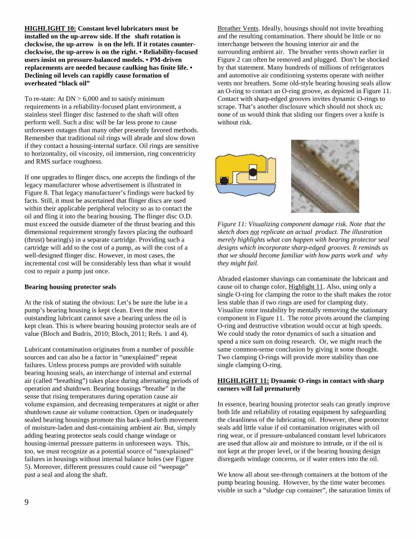
Breather Vents. Ideally, housings should not invite breathing and the resulting contamination. There should be little or no interchange between the housing interior air and the surrounding ambient air. The breather vents shown earlier in Figure 2 can often be removed and plugged. Don’t be shocked by that statement. Many hundreds of millions of refrigerators and automotive air conditioning systems operate with neither vents nor breathers. Some old-style bearing housing seals allow an O-ring to contact an O-ring groove, as depicted in Figure 11. Contact with sharp-edged grooves invites dynamic O-rings to scrape. That’s another disclosure which should not shock us; none of us would think that sliding our fingers over a knife is without risk.
Figure 11: Visualizing component damage risk. Note that the sketch does not replicate an actual product. The illustration merely highlights what can happen with bearing protector seal designs which incorporate sharp-edged grooves. It reminds us that we should become familiar with how parts work and why they might fail. Abraded elastomer shavings can contaminate the lubricant and cause oil to change color, Highlight 11. Also, using only a single O-ring for clamping the rotor to the shaft makes the rotor less stable than if two rings are used for clamping duty. Visualize rotor instability by mentally removing the stationary component in Figure 11. The rotor pivots around the clamping O-ring and destructive vibration would occur at high speeds. We could study the rotor dynamics of such a situation and spend a nice sum on doing research. Or, we might reach the same common-sense conclusion by giving it some thought. Two clamping O-rings will provide more stability than one single clamping O-ring. HIGHLIGHT 11: Dynamic O-rings in contact with sharp corners will fail prematurely In essence, bearing housing protector seals can greatly improve both life and reliability of rotating equipment by safeguarding the cleanliness of the lubricating oil. However, these protector seals add little value if oil contamination originates with oil ring wear, or if pressure-unbalanced constant level lubricators are used that allow air and moisture to intrude, or if the oil is not kept at the proper level, or if the bearing housing design disregards windage concerns, or if water enters into the oil. We know all about see-through containers at the bottom of the pump bearing housing. However, by the time water becomes visible in such a “sludge cup container”, the saturation limits of

10
oil-in-water will have been exceeded and much damage could have been done to the bearings. We can deduce that free water in the oil is a symptom of not having the right bearing housing protection. Our reliability focus should be on treating the root cause, not the symptom. We should prevent water from reaching the bearings in the first place. These proactive and precautionary thought processes are at the core of this tutorial on pump failure prevention. Ranking the different lube application practices Although oil ring lubrication is widely used, it is relatively maintenance-intensive and ranks last from the author’s experience and risk reduction perspective. Next, flinger discs have been used for many decades and allow operation at higher DN values than oil rings. Because they are firmly clamped to the shaft there is far less sensitivity to installation and maintenance-related deviations. On the other hand, non-clamped flinger discs were tried a few decades ago, and with very disappointing results. API-610 therefore disallows push-on flingers and some other low-cost oil application components (American Petroleum Institute, 2009; Ref. 23). HIGHLIGHT 12: Pure oil mist represents many decades of fully proven technology Plant-wide oil mist lubrication systems are ranked ahead of flinger discs. Oil mist has proven superior to conventional lubricant application since the late 1960’s. Pump bearing failure reductions ranging from 80 to 90% have been reported by Charles Towne of Shell Oil, and many others (Miannay, 1974; Shamim and Kettleborough, 1994; Shamim and Kettleborough, 1995; Ehlert, 2011; Refs. 25 through 29). Charles Towne performed tests on identical process units at Shell Oil and deserves much credit for his seminal work on the subject. See Highlight 12 for a summary. The highly beneficial in-plant, real-life results reported by Towne (Shell Oil) refer to pure oil mist, not purge mist. Pure oil mist is an oil-air mixture with a volumetric ratio of 1:200,000. The oil is atomized to globule form and carried by the air, applied in modern plants as shown in Figure 12. The same illustration, Figure 12, could also be used to depict liquid oil spray. Liquid oil spray is sometimes called “jet oil” lubrication (Bloch, 2011; MRC Co, 1982; Refs. 4 and 8) and differs from oil mist. HIGHLIGHT 13: Bearing manufacturers rank spraying liquid oil into a bearing’s cage a bit higher than the widely practiced (and quite cost-effective) oil mist (oil fog) application These facts and findings are summarized in Highlight 13. And so, with regard to the introduction of liquid (not misted) lube oil into rolling element bearings, Figure 13 incorporates a number of very important recommendations for the truly reliability-focused:
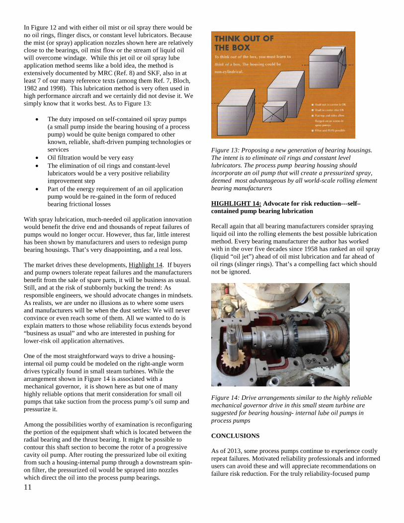
• It conveys that pump bearing housings need not be symmetrically configured. Asymmetry is visualized by
looking into the pump shaft. The distance to the right edge of the bearing housing is not the same as the distance to the left edge of the bearing housing. The volume thus gained could accommodate a small oil pressurization pump; this small pump would be arranged inside the process pump’s bearing housing.
• A box-like geometry with a flat cover and ample space to incorporate a wide range of oil pumps is feasible. Box-like bearing housings for process pumps would open up a host of new and inventive solutions. These might incorporate shaft-driven or other reliable self-contained means or oil application pumps (Bloch, 2001; Ref. 30). The oil application pump would possibly take suction from an increased-size oil sump.
• The main process pump shaft need not be in the geometric center of the box.
• Flat surfaces would invite clamp-on, screw-in or flange-on oil pumps.
• Oil pressurized by the oil application pump would be routed through a filter and hydraulic tubing to spray nozzles incorporated in the end caps. Therefore, the cross-section view of a bearing housing with oil spray would be identical to the one shown for oil mist in Figure 12 (Bloch and Shamim, 1998; Ref. 14)
• Internal pressure equalization and windage issues would never again be a concern.
• The incremental cost of superior bearing housings would be more than matched by the value of avoided failures.
Figure 12: Oil mist lubrication applied to a pump bearing housing in accordance with API 610, 10th Edition (Bloch and Shamim, 1998; Ref. 14). With oil spray lubrication, liquid oil would enter at the nozzles. Note the dual mist (or, for spray lube application, dual liquid oil) injection points. Observe dual-face magnetic bearing housing seals that prevent oil mist (or oil spray) from escaping to atmosphere.
11
In Figure 12 and with either oil mist or oil spray there would be no oil rings, flinger discs, or constant level lubricators. Because the mist (or spray) application nozzles shown here are relatively close to the bearings, oil mist flow or the stream of liquid oil will overcome windage. While this jet oil or oil spray lube application method seems like a bold idea, the method is extensively documented by MRC (Ref. 8) and SKF, also in at least 7 of our many reference texts (among them Ref. 7, Bloch, 1982 and 1998). This lubrication method is very often used in high performance aircraft and we certainly did not devise it. We simply know that it works best. As to Figure 13:
• The duty imposed on self-contained oil spray pumps (a small pump inside the bearing housing of a process pump) would be quite benign compared to other known, reliable, shaft-driven pumping technologies or services
• Oil filtration would be very easy • The elimination of oil rings and constant-level
lubricators would be a very positive reliability improvement step
• Part of the energy requirement of an oil application pump would be re-gained in the form of reduced bearing frictional losses
With spray lubrication, much-needed oil application innovation would benefit the drive end and thousands of repeat failures of pumps would no longer occur. However, thus far, little interest has been shown by manufacturers and users to redesign pump bearing housings. That’s very disappointing, and a real loss. The market drives these developments, Highlight 14. If buyers and pump owners tolerate repeat failures and the manufacturers benefit from the sale of spare parts, it will be business as usual. Still, and at the risk of stubbornly bucking the trend: As responsible engineers, we should advocate changes in mindsets. As realists, we are under no illusions as to where some users and manufacturers will be when the dust settles: We will never convince or even reach some of them. All we wanted to do is explain matters to those whose reliability focus extends beyond “business as usual” and who are interested in pushing for lower-risk oil application alternatives. One of the most straightforward ways to drive a housing-internal oil pump could be modeled on the right-angle worm drives typically found in small steam turbines. While the arrangement shown in Figure 14 is associated with a mechanical governor, it is shown here as but one of many highly reliable options that merit consideration for small oil pumps that take suction from the process pump’s oil sump and pressurize it. Among the possibilities worthy of examination is reconfiguring the portion of the equipment shaft which is located between the radial bearing and the thrust bearing. It might be possible to contour this shaft section to become the rotor of a progressive cavity oil pump. After routing the pressurized lube oil exiting from such a housing-internal pump through a downstream spin-on filter, the pressurized oil would be sprayed into nozzles which direct the oil into the process pump bearings.
Figure 13: Proposing a new generation of bearing housings. The intent is to eliminate oil rings and constant level lubricators. The process pump bearing housing should incorporate an oil pump that will create a pressurized spray, deemed most advantageous by all world-scale rolling element bearing manufacturers HIGHLIGHT 14: Advocate for risk reduction---self–contained pump bearing lubrication Recall again that all bearing manufacturers consider spraying liquid oil into the rolling elements the best possible lubrication method. Every bearing manufacturer the author has worked with in the over five decades since 1958 has ranked an oil spray (liquid “oil jet”) ahead of oil mist lubrication and far ahead of oil rings (slinger rings). That’s a compelling fact which should not be ignored.
Figure 14: Drive arrangements similar to the highly reliable mechanical governor drive in this small steam turbine are suggested for bearing housing- internal lube oil pumps in process pumps CONCLUSIONS As of 2013, some process pumps continue to experience costly repeat failures. Motivated reliability professionals and informed users can avoid these and will appreciate recommendations on failure risk reduction. For the truly reliability-focused pump

12
users, a number of conclusions and upgrade recommendations may be of interest:
1. Discontinue using maintenance-intensive oil rings and, if possible, constant level lubricators.
2. As a matter of routine, the housing or cartridge bore should have a passage at the 6 o’clock position to allow pressure and temperature equalization and oil movement from one side of the bearing to the other. Note that such a passage was shown in Figure 3 for the radial bearing, but not for the thrust bearing set.
3. With proper bearing housing protector seals and the right constant level lubricators, breathers (or vents) are no longer needed on bearing housings. The breathers (or vents) should be removed; one of the openings in Figure 3 can often be plugged.
4. If constant level lubricators are used, a pressure-balanced version should be supplied and its balance line should be connected to the closest breather port.
5. Bearings should be mounted in suitably designed cartridges and loose slinger rings (oil rings) should either be avoided or, in some high DN cases, disallowed.
6. Suitably designed flinger discs should be secured to the shaft whenever the oil level is lowered to accommodate the need to maintain acceptable lube oil temperatures (i.e., for pumps operating with DN-values in excess of 6,000).
7. Modern and technically advantageous versions of bearing housing protector seals should be used for both the inboard and outboard bearings. Lip seals are not good enough, and neither are outdated rotating labyrinth seal designs.
8. Understand that the implementation of true reliability-thinking must strongly support moves away from traditional bearing housings. These moves involve pushing for exploration of the alternatives alluded to in Figures 13 and 14.
Knowledgeable engineers can show that some widely accepted pump components tend to malfunction in the real world. Moreover, as industry often moves away from solid training and from taking the time needed to do things right, designing-out risk and designing-out maintenance become attractive propositions. REFERENCES
1. Bloch, H. P., and Budris, A.; (2010), “Pump User’s Handbook—Life Extension,” 3rd Edition, Fairmont Press, Inc., Lilburn, GA 30047; (ISBN 0-88173-627-9).
2. Taylor, I.; “The Most Persistent Pump-Application Problems for Petroleum and Power Engineers,” ASME Publication 77-Pet-5 (Energy Technology Conference and Exhibit, Houston, Texas, September 18-22, 1977).
3. Karassik et al; “Pump Handbook,” (1985), 2nd Edition, McGraw-Hill, New York, NY, (ISBN 0-07-033302-5).
4. Bloch, H. P.; (2011) “Pump Wisdom,”, John Wiley & Sons, New York, New York,
(ISBN 9-781118-041239).
5. SKF Americas, General Bearing Catalog, (1990) Kulpsville, Pennsylvania.
6. Worthington Pump Company, 1968, Pump Operation and Maintenance Manual.
7. Bloch, H. P.; (1982, 1998), “Improving Machinery Reliability,” 3rd Edition, Gulf Publishing Company, Houston, Texas.
8. MRC Bearings General Catalog 60, “TRW Engineer’s Handbook,” 2nd Edition (1982), p. 197.
9. Eschmann, Hashbargen and Weigand; (1985), “Ball and Roller Bearings: Theory, Design, and Application, John Wily & Sons, New York, NY; ISBN 0-471-26283-8.
10. Bloch, H. P.; (2009), “Practical Lubrication for Industrial Facilities,” 2nd Edition, Fairmont Press, Lilburn, Georgia, 30047; (ISBN 088173-579-5).
11. SKF USA, Inc.; (1995) “Bearings in Centrifugal Pumps, SKF Publication 100-955, Second Edition.
12. Wilcock, D. F., and Booser, E.R.; (1957), “Bearing Design and Application,” McGraw-Hill Publishing Company, New York, NY.
13. Bloch, H. P. (1987), “Oil Mist Lubrication Handbook,” 1st Edition, Gulf Publishing Company, Houston, Texas.
14. Bloch, H. P. and Shamim, A.; (1998), “Oil Mist Lubrication--Practical Application” Fairmont Press, Lilburn, Georgia, 30047; (ISBN 088173-256-7).
15. Baudry, R. A., and Tichvinsky, L.M.; (1937), “Performance of Oil Rings,” Mechanical Engineering, 1937, Volume 59, 89-92; also ASME, Journal of Basic Engineering; (1960) 82D, pp. 327-334.
16. Heshmat, H., and Pinkus. O.; (1984), "Experimental Study of Stable High-Speed Oil Rings," (1984) American Society of Mechanical Engineers (Paper); also (1985) Journal of Tribology, Volume 107 (1), pp. 14-22.
17. Hersey, M.D., “Discussion of Performance of Oil Rings”, Mechanical Engineering, 1937, Volume 59, 291.
18. Urbiola Soto, L.; “Experimental Investigation on Rotating Magnetic Seals,” Masters Thesis, Texas A&M University, 2001/2002.
19. Government of Malaysia, Department of Occupational Safety and Health http://www.dosh.gov.my/doshv2/index.php?option=com_content&view=article&id=424%3Afire-at-oil-refinery&catid=84%3Asafety-alerts&Itemid=118&lang=en .
20. Bloch, H. P.; “Deferred Maintenance Causes Upsurge in BFW Pump Failures”, Hydrocarbon Processing, May 2011 [based on consulting work by the author]
21. Bradshaw, S.; “Investigations into the Contamination of Lubricating Oils in Rolling Element Pump Bearing Assemblies,” (2000), Proceedings of the 17th International Pump User’s Symposium, Texas A&M University, Houston, Texas.
22. TRICO Manufacturing Corporation, Pewaukee, WI; Commercial Literature, 2008; also www.tricocorp.com.
23. American Petroleum Institute, Alexandria, VA, API-610 “Centrifugal Pumps”, 10th Ed.
24. Towne, C. A., “Practical Experience with Oil Mist Lubrication,” (1983), Lubrication Engineering, Vol. 39 (8), pp.496-502.

13
25. Miannay, C. R. “Improve Bearing Life,” Hydrocarbon Processing, May 1974.
26. Shamim, A., and Kettleborough, C.F., “Tribological Performance Evaluation of Oil Mist Lubrication,” ASME Journal of Energy Resources Technology, Vol. 116, No. 3, pp. 224-231 (1994).
27. Shamim, A., and Kettleborough, C.F., “Aerosol Aspects of Oil Mist Lubrication Generation and Penetration in Supply Lines,” presented at the Energy Resources Technology Conference and Exhibition, Houston, Tribology Symposium ASME, PD - Vol. 72, pp. 133-140 (January 1995).
28. Ehlert, D.; “Getting the Facts on Oil Mist Lubrication,” Texas A&M Middle East Turbomachinery Symposium, (2011).
29. Ehlert, D.; “Consider Closed-Loop Oil Mist Lubrication;” Hydrocarbon Processing, June 2011.
30. Bloch, H. P.; “Inductive Pumps Solve Difficult Lubrication Problems;” Hydrocarbon Processing, September 2001.