solvent recovery using the brayton cycle heat pumpinfohouse.p2ric.org/ref/23/22307.pdf · ·...
TRANSCRIPT
Solvent Recovery Using the Brayton Cycle Heat Pump
Nirmal Jain 3M
Paul E. Scheihing Program Manager
U. S. Department of Energy Office of Industrial Technologies
Abstract
A progression of designs to control volatile organic compound (VOC) emission streams
using a reverse Brayton cycle are described in this paper. An advanced design, soon to be
built, is the result of an intensive cooperative effort of 3M, Nucon Intemational and the
U.S. Department of Energy (DOE) over the last two ycars. The new advanced design
benefited from a development effort started by 3M in 1975. Similarly, Nucon and the U.S.
DOE have been involved with 3M since the early 1980’s in the development of the Brayton
Cycle Heat Pump (BCHP) for solvent recovery, ncycle and reuse. The technical
performance along with the estimated costs of an 8OOO S C F M BCHP (that is used in
conjunction with solvent concenuating adsorption beds) at a 3M manufacturing plant is
detailed.
Introduction
The use of solvents in industry is widespread. Solvent use affects a large cross-section of
products such as adhesive tape. plastic foams, synthetic fibers, electronic components,
furniture manufacturer and many more. Recently. environmental concans have prompted
stricter legislation to control VOC emissions (Le. The Clean Air Act). At the same the thc
price of s m e solvents has increased significantly forcing industry to search for cost
effcctive alternatives to manufacture profitably yet within environmental regulations.
Industry is thus presented with the following choices:
1) Eliminate the n d for solvents in the manufacture of their product
2) Reduce VOCs by making the process "tighter" (is. prevent fugitive emissions).
3) Control VOCs by incineration or destruction.
4) Control VOCs by capturing and recycling them back to reusable solvent
3M uses solvents to manufacture a variety of products (eg. adhesive tape. magnetic tape or
discs. and other products requiring coating). A corporate wide effort has been
implemented by the top management to reduce VOC emissions by 90 percent by the y ~ a r
UXK). Thcrcforc, al l of the four choi& above arc being considered.
Controlling VOCs by capture on activated carbon adsorption beds is common in industry
today. Although the number of solvent control devices number in the thousands in the
U.S.. the level of VOCs that are uncontrolled is by far greater. The US. DOE recognizes
the expanse of solvent recycling throughout the nation as an opportunity to save a
significant amount of energy (SO trillion BTUs annually valued at over 200 million dollan).
This energy savings will result from more energy efficient VOC control quipment to be
brought to the marketplace and the saving of the embodied energy of the solvent (i.e. the
aggregate of the process energy and feedstock fuel heating value energy required to
manufacture the solvent is the embodied energy).
DOE P W t O b 7
T h a arc two main goals of this project
. .
Gd-L The first goal is to demonstrate cconomic solvent recovery for large VOC emission points (e.g. a loo0 ton pcr year VOC source). A payback of less
than threc years based on the total installed cost of the quipment with
solvents moderately priced at 30 cents per pound, independent of
arvironmental ngulatory costs, is a target that DOE and 3M want to achieve.

!hU The second goal is directed at small solvent u s m of less than 500 tons per
year. The mobile BCHP should demonstrate to small solvent users (100 tons
per year on average) that the annualii costs of this technology can conaol
many different types of VOC sources at under $loo0 per ton
Of course, these two goals must be achieved concurrent with reliable equipment, enagy
efficient equipment and equipment able to meet environmental regulations.
3M and the U.S. DOE are working cooperatively to develop an advanced BCHP
system. DOE will fund 3M (on a cost sharing basis) to design. manufacture and field
test an 8000 SCFM BCHP system that will be installed at the 3M Grecnville. SC
manufacturing plant to control a loo0 ton pcr year VOC emission source. Nucon
International of Columbus. Ohio, is assisting 3M on this project by providing ~ ~ O C C S S
engineering, equipment design and manufacture and installation of the packaged
BCHP ngeneration/VOC adsorption system.
voce- .. .
The Gmvil le plant application is a relatively large VOC control application VOC
emission source greater than 500 tons per ycar probably accounts for less than 10
percent of the total VOC emissions. Thenforr. DOE will cooperatively work with
Nucon International to cost effectively develop a B m to conml small VOC emission
points (e.g. less than 500 tons pa year). ?his project wil l mobilize the BCHP and thus
allow a single mobile BCHP system to regenerate numerous concentration beds at
scattered industrial host site lodons. In this way the capital cost of the mobde BCHP
(estimated at $300.000 to $400.000) can bc distributed amongst many industrial

solvent users. Southern California Edison (SCE) and The Electric Power Research ' h
1) Institute (EPRI) are co-sponsonng this project wlth Nucon, 3M and the DOE, and
therefore, the host sites will be located in the Southern Califomia area. Figure 1 shows
the small mobile BCHP system that will initially be demonstrated to four companies in
Southem California. Applicability of the Brayton concept in solving their specific VOC
recovery problem will be evaluated. 4
Figure 1 - Small Mobile Brayton Cycle Heat Pump System
of the Bravton Cvck
The BCHP is an altcmative means of condensing solvents from a gas stream by use of a
reverse Brayton cycle. Many solvent streams must be refrigerated to temperatures bclow
- 5O0F ( - 4 5 O C ) to condense greater than 90 percent of the solvent in a single pass through
the condensing system. Other refrigeration methods, such as a reverse Rankine Cycle using
refrigerants in a closed cycle loop can be and have been used to condense solvenu to these
low temperatures. (Comparison of the Brayton cycle to the Rankine cycle will bc
later).

To illustmte how refrigeration is accomplished with the reverse Brayton cycle, F i p 2
shows an ideal regenerative reverse Brayton cycle on a tcmperaturdenmpy diagram. At
station 1 the solvent laden gas stream is compressed isentropically to station 2. Heat is
extracted in the regenerator from station 2 to 3 at constant pressure. Because h a t is
extracted from station 2 to 3 the cycle is termed a reverse Brayton cycle. If heat was added
by heat exchange or combustion (such as in a gas turbine power plant or jet engine), then
the cycle would be a forward Brayton cycle. At station 3 the gas strcam tanperatwe will be
cold enough to condense a majoxity of the solvents. From station 3 to 4 the gas stream has
work extracted isentropically in an expander (turbine) to lower the gas s t ” temperatwe
even further. (Tempuaturcs as low as -1MOF ( - 1 0 1 O C ) can be achieved in a single stage of
compression and expansion). Essentially a l l of the remaining solvents arc condensed at
station 4. The work produced by the expander partially drives the compressor. The
remainder of the compressor work requirement comes from mechanical shaft work input.
The cold gases at station 4 arc then passed through the other side of the regenerator to
m u p heat at constant pressure to complete the cycle.
Regenerator 5
dtTl a e a n Air lo Pmceaa
t Uquld Solvents Out
Entropy
Figure 2 - Description of the Reverse Brayton Cycle with Solvent Rtcovcry

' ? &though the Brayton cycle requires high sped turbomachincry. this machinery is
commonly used today. AU air conditioning systems used on commercial and military jet
akcraft use a reverse Brayton cycle system. For aircraft applications, the Brayton
refrigeration method has been sclccted for reasons of low weight and high reliability.
Another application of the reverse Brayton cycle is a cryogenic air separation plants. Here
too. nliabaty has been good for over fifty yeas. At present, the most common application
of the Brayton cycle is thc automotive turbocharger.
As mentioned, 3M has actively pursued the BCHP for the past 15 ycars. Bryce Fox (a
ntircd 3M engineer) was the champion of this technology and is named sole or joint
inventor on three 3M patents. (1). @h 0)
In 1979 3M funded the AiRescarch Manufacturing Company (a division of the Gamtt
Corporation) to provide a 2000 SCFM prototype Bmyton cycle system. This was used to i
process a solvent laden gas strcam from an inert gas drier at 3M. In showing feasibity
and successful operation of this system, the U.S. DOE decided to fund a larger 9OOO
SCFM unit that was installed a! 3M's Hutchinson. MN tape manufacturing plant Both of
these systems directly condense the solvents by processing the solvent laden air (SU)
from the coating proccss through the BCHP.
-
Both the 2000 and 9000 SCFM system designed'by AiResearch used specidly
manufactured gear boxes that were costly. The system installed at the Hutchinson p h t
(sec Figm 3) shows the gear box coupling thc input shaft power (an elccaic motor
running at 3600 WM) to a high spocd comprcssor/turbine unit running at 16.500 RPM.

Figure 3 - Simplified 9OOO SCFM 3M Hutchinson Brayton Systcm
Learning from the experiences of the Hutchinson system, 3M worked with Nucon to
design and install the second industrial B r a p n cycle system at the 3M Weatherford, OK
plant beginning in 1985. The Weatherford design differed from the Hutchinson design as
follows:
1) Activated carbon bcds arc use to adsorb and concentrate solvent from the Voc s”.
2) ThC BCHP is used to regenerare the carbon bed with inert niaogen gas.
3) A molecular sieve is used as an i”cdiatc step between the adsorption and
regmuation of the carbon bed to eliminate water (and thus ice formation) fium the
BCHP solvent ladca nimga st”.
4) A free spindle comprcssor-ucpanda is used in combination with a rotary blow= to
provide the comprcssor/expansion package. That is. the shaft power input to the
BCHP systcm was decoupled from the compn,ssor/cxpanda package to e l i i

the high speed gear box used in the Hutchinson design. This free spindle
compressor/expander was a modified design of the Garrett Indusnid Products
Division's largest diesel turbocharger.
Figure 4 shows the overall solvent recovery process in which the two carbon beds arc
cycled between stcp 1 and steps 2 to 4. That is. while one bed is adsorbiig solvents at step
1, the other is being regenerated by step 2 (carbon dehydration), step 3 (carbon solvent
desorption with the revasc Brayton cycle) and step 4 (molecular sieve regeneration).
The Weatherford system has been operating for o v a 1.5 ycars with over 99 percent up
time. A more detailed description of the Weatherfd process is presented in rcfcrcncc (4)
by Kovach of Nucon.
Prowst (2 Beds)
Step 1 Solvent Adsorption
I I
U Step 2
Carbon Dehydration
Step 3 - Carbon Regeneration Slep 4 Molecular Sieve Regeneration (Reverse Brayton Cycle)
fim 4 - 3M Wcathafard Brayt~dCon~~~orator System - ovaall Process
/"-a .i

Bra-
In considering the recycle of solvents, equipment selection wil l be dictated by capital and
operating c o s t The solvent type. VOC sueam flow size, VOC concentration level and the
degree to which the VOC must be controlled (is. percent recovery) arc all factors
influencing cost
To U m t e the economics of solvent nzycling. the Greenville plant installation costs will
be detailed for the ppsd advanced Braycon design and other altunative approaches to
controlling the VOC emissions from the coatcr at this plant. The VOC stream to be
conuollcd at Greenville is an 8000 SCFM SLA stream with a concentration of
approximately 2000 ppmv. The solvents used are heptane, xylene, toluene and
isopmpylalcohol (PA).
Figure 5 shows the preliminary design of the advanced Brayton system. The Brayton
regeneration system will provide a dry incrt nitrogen smcam for solvent smpping to one Of
the two adsorbent beds and then will remove o v a 99 percent of the solvents from the
solvent laden nitrogen (SLN) once the SLN is retumed from the adsorption bed. (The
other adsorption bed is adsorbing solvents from the SLA stream coming from the water.)
This process was developed by Nucon under Phase I of the DOE project. The process is
trade marked BRAYSORB’. Figure 6 shows the tempcram versus pressure plot of this
system. Note that the temperature of the adsorba is 320OF (160OC) and therefore no
additional process heating is needed to regencrate the adsorbent beds. This means that
electricity is only needed to drive the Brayton system eliminating the need for stcam
production or a u x i b y hcating systems.
-

TO ACSOREER
N R B O COMPRESSOR
240
0 5 10 15 20 25 SYSTEM PRESSURE - PSlA
Figure 6 - Tempuaturc versus Rcssurc Plot of BRAYSORBm Roccss

Figure 7 shows a generic steam regeneration system analyzed for evaluation purposes to
determine cost competitiveness of the Bxayton system to otha alternative designs. If the
solvents are not miscible or slightly miscible, a decanting system wil l separate the majority
of the solvents from the steam condensate satisfactorily. The contaminated condensate.
however, will necd to be treated by an sir m i p .
COOUNG WATER
’I A 4 A
I CONDENSER II
Figure 7 - Steam Regenexation System with Decanting SolvcnWater Separation
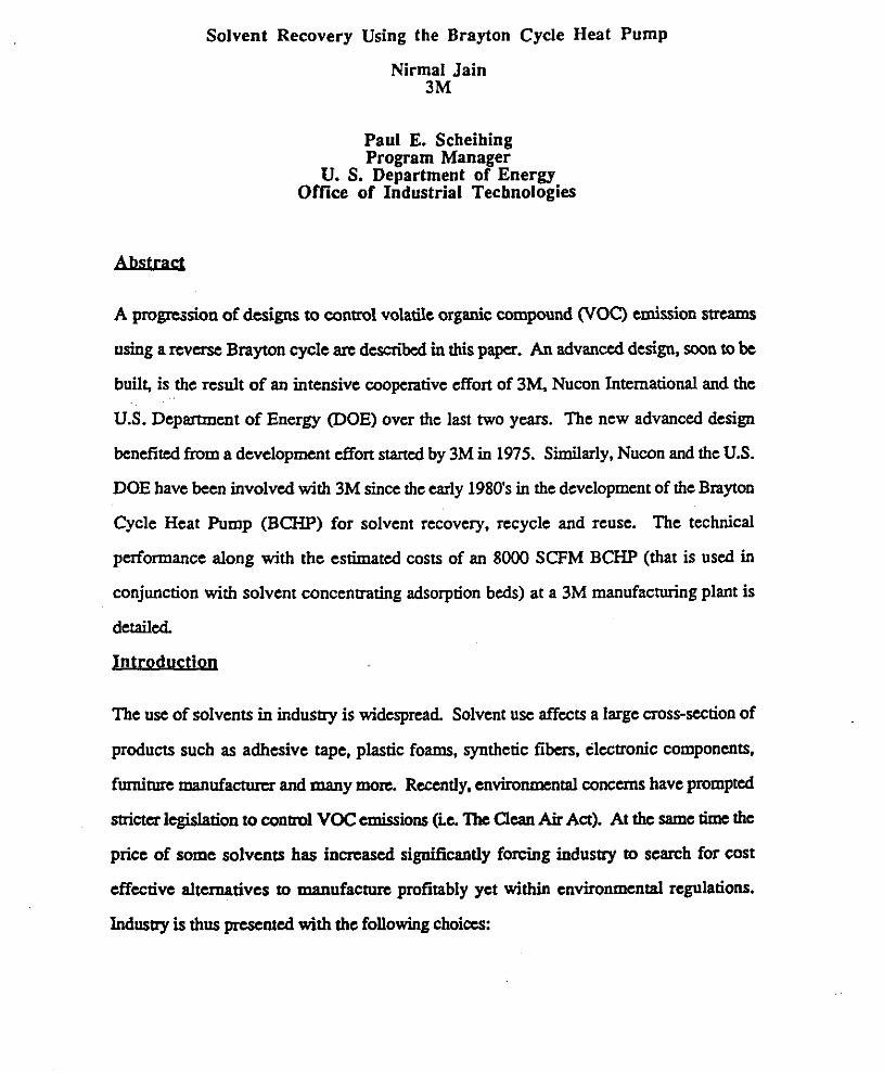
Figure 8 shows a schematic of a revase Rankine system ?his system has two cooling
systems, one with a 30°F (-lac) and one with a -80°F (-62’0 Cpaporator coil cooling
t e T t W C . The SLN Strtam is cooled to -75OF (-5S”c) which is the S B ~ C t e ~ m Bs
that achieved by the Brayton system. This allows for qual comparison of the Brayton and
Rankine systems since approximately the same percent solvent recovery should be
accomplished.
F
Figure 8 - Rcvasc Rankine coOlcd/Incrt Gas Regeneration System
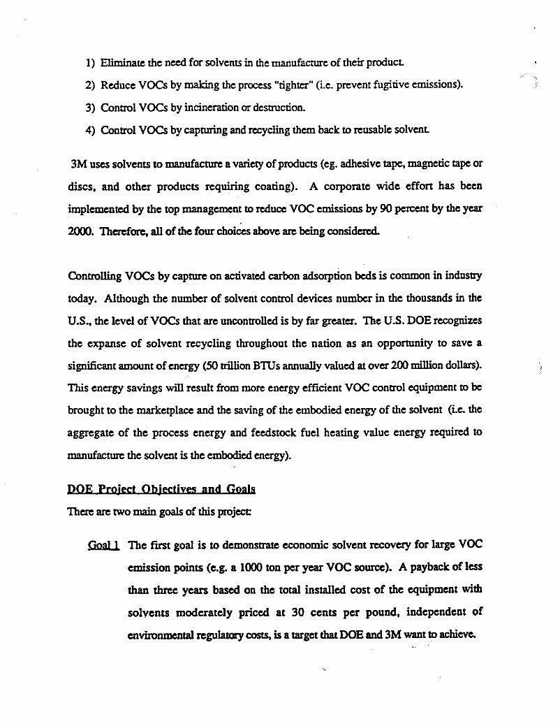
Finally, an incineration system is shown in Figure 9. This system is a high eKciency unit
since heat regeneration takes place. No heat recovery is attempted to provide heat to the
plant's utilities needs. The solvents that are burned account for over 50 percent of the fuel
heating value in the combustion pmess.
Figure 9 - Rcgemmive Inciaemtion Sysmn
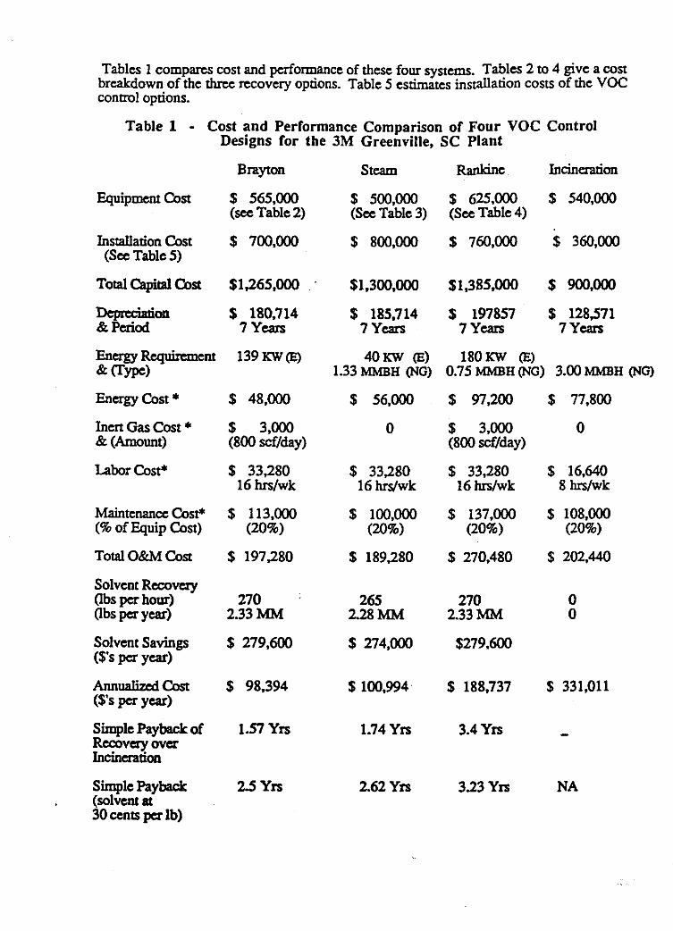
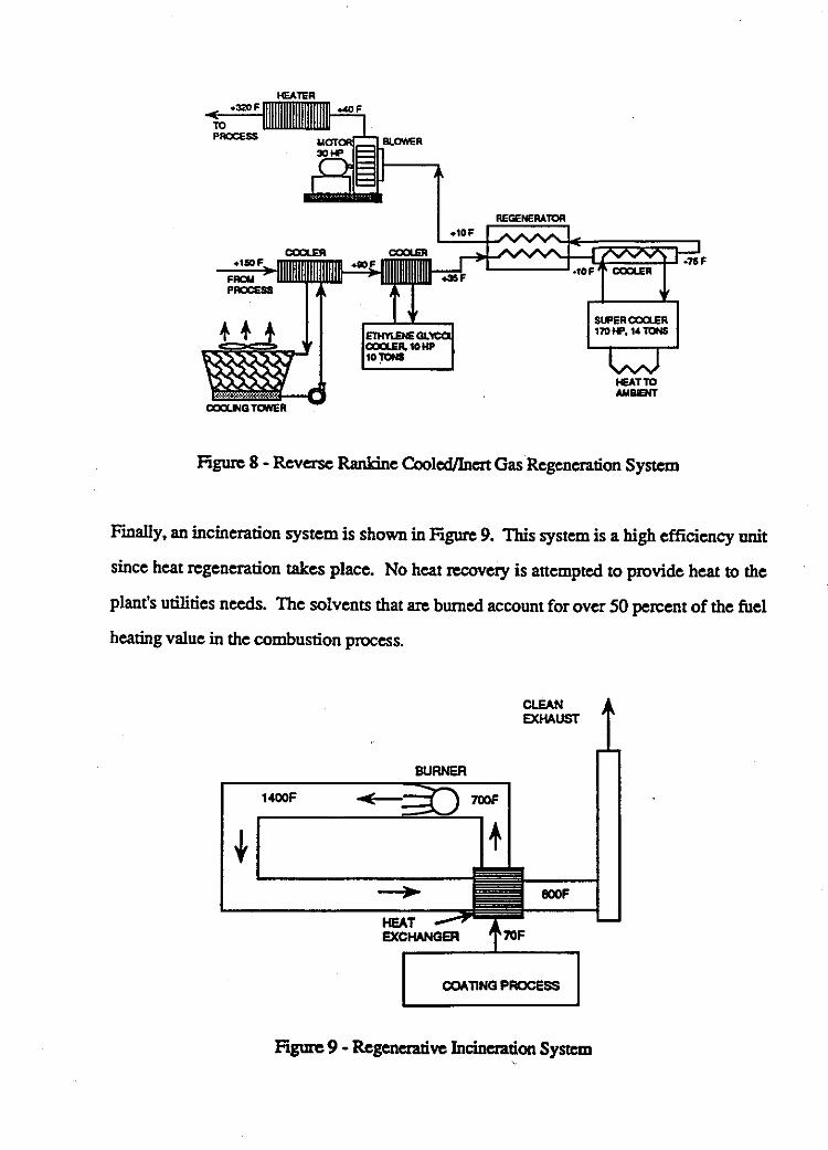
Tables 1 compares cost and performance of these four system. Tables 2 to 4 give a cost breakdown of the three ncovery options. Table 5 estimates installadon costs of the VOC conml options.
Table 1 - Cost and Performance Comparison of Four VOC Control Designs for the 3M Greenville, SC Plant
Brayton stcam Rankine Incineration
Equipment cost $ 565.000 $ 500,000 $ 625.000 $ 540,000 (sec Table 2) (See Table 3) (See Table 4)
Installation Cost $ 700,000 $ 800,000 $ 760.000 $ 360,000 (See Table 5)
Total capital &st $1,265,000 $1.300,000 $1,385,000 $ 900,OW
Dcprcciation $ 180,714 $ 185.714 $ 197857 $ 128,571 & Period 7 Years 7 Years 7 Yuvs 7 Ycars
E n a g y R ~ @ ~ ~ ~ n t 139KWo 4OKW (E) 180KW (E)
Energy cost * $ 48,000 $ 56.000 $ 97,200 $ 77.800
Inert Gas Cost * $ 3.000 0 $ 3,000 0 & (Amount) (800 scf/day) (800 scUday)
Labor Cost* $ 33,280 $ 33,280 $ 33,280 $ 16,640 16 h / w k 16 W w k 16 hrs/wk 8 hrs/wk
Maintenancecost+ $ 113.000 $ l00,OOO $ 137.000 $ 108.000
VYPd 1.33 MMBH (NG) 0.75 MMBH (NG) 3.00 MMBH (NG)
(% of Equip cost) (20%) (20%) (20%) (20%)
Total O&M Cost $ 197,280 $ 189.280 $ 270,480 $ 202,440
(lbs pa hour) 270 265 270 0 Obs pa year) 2.33 MM 2.28 MM 2.33 MM 0
($Is pa Year)
(VS pcr Year)
Sirnple Payback of 1.57 Yrs 1.74 Yrs 3.4 Yrs - Rccoveryov~ Incinmtim
simple Payback 2 5 Yrs 2.62 Yrs 3.23 Yrs NA (solvent at 30 cents pa lb)
Solvent Recovery
Solvent Savings $ 279.600 $ 274.000 $279.600
Annualizcdcost $ 98.394 $100.994 $ 188,737 $ 331,011
.- I

. operation hours per year - 8640 electricity rate - 4 ccntdKw-Hr natumlgascost - $3.00MMBTU boiicreffciency - 75% laborrate - WperHr solvent mycle value - $.12ilb
* Costs arc annual E = Elccaicity NG = N a W Gas MMBH = Million BTU/Hr
Table 2 - Brayton Regenerated System Cost Breakdown
Free-spindle Complwsor&anda Drive compressar Regenerative Heat Exchanger Precoolcr (water cooling) Piping & valves Separators & Rcceivcrs Instrumentation & Controls Structural Slddding. Mounting, Misc. Adsorber Structure (Carbon Steel) Activated Carbon (20.000 lbs @ $2/lb)
Total Equipment Cost Engineering Profit
$ 40,000 $ 40,000 $ 40.000 $ 10.000 s 5 o . m $ 30366 $ 90,000 .S 40.000 $ 60.000 %40.000
$440.000 $ 75,000 50.000
Total Equipment Cost $565.000
Table 3 - Steam Regenerated System Cost Breakdown
Boiler(1o0olblhrsrcam) D e C a n t a 8 i C o n d ~ Piping&ValVes '
Insmm"aon & Controls Structural Slddding. Mounting, Misc. AdsorbaStructurt (304 Stainless) Activated Carbon (20,000 Ibs @ $2/lb) cooling Tower Wata Treatment System Total Equipment Cost &fit Engineaing
$ 20.000 s 5o.m s, s0;ooo $ 50.000 $ 4o.m $ 80.000 $ 40.000 $ 30.000 w $410,000 $ 50,000 s-LlomQ
', - !& 3
Total Equipment Cost $500.000 * Site dependent - Cost may be as high as $500.000

Table 4 - Rankine Regenerated System Cost Breakdown
Precooler (water mling) pncooling Refrigeration Unit Regenerative Heat Exchanger Supercooler Refiigeration Unit Regenerator Blower Heating Unit Piping & valves Separators & Receivers Instrumentation & Conmls Adsorbcr Smcturc (Carbon Steel) Activated Carbon (24),000 lbs @ $2/lb) Total huipmcnt Cost EnginctMg profit
Total Equipment Cost
$ 10.000 $ 20,000 $ 20.000 $ 150,000 $ 10,000 $ 10.000 $ 50,000 $ 30.000 $ 90,000 $ 60,000 %40.000 $490,000 $ 75,000 La!aXl $625.000
Table 5 - Cost Breakdown of Installation of VOC Control
YQ€k=cL Enginming $ 50,000 SLA Fan. Filter, cooler. Ducting $l00,OOo Site Preparation * $250,000 TankFarms $150.000 Equipment Installation $100,000 Process Instrumentation L5Q.mQ Total Installation Cost $700.000
$ 50.000 $100.000 $120,000 $ 0 $ 40.000 %50.000 $360.000
* Add $60,000 for a building enclosure on the Rankine system * Add %lOO,000 for a cooling tower installation for a Stcam system
A few mnclusions can bc made from the above tables:
1) AU the solvent r ~ ~ o v c r y technologies have lower annualized operating cost than
incineration. Also. the incremental investment of a l l three recovery technologies
over the cost of the incineration system yields a 1.5 to 3.5 years payback based on
the aggregate savings of thc recycled solvents and the difference in o p t i n g cosfs
of the rccovQy options and incindon. In the future if the solvent price WQC. fa
instance, 30 cents per pound for this application then the payback on Brayton and
stcam regeneration system would be lcss then 3 years.

The Brayton system costs arc estimated to be competitive with the well established
recovery technologies. This cost estimate of the Brayton system is for the third
generation design. Furthcr cost duction can be expected in the future. For this
reason. 3M is pursuing this technology so that their choices on controlling VOCs
may be broadened. Likewise. the DOE secs the Brayton technology as a vehicle to
reduce energy consumption of VOC control technologics and, to proliferate solvent
ncycling with mort cost effective recycling with both large and small solvent USQS
and thereby reduce demand for energy intensive solvent production nationwide,
of the Bravton Cvcle Technologv
The main accomplishments over the last 15 years on the Brayton cycle solvent recovery
technology have been to reduce capital cost, reduce energy consumption and improve
reliability of the equipment Table 6 summarizes the performance of the two 3M Brayton
systems already installed (Hutchinson and Weatherford) and the expected performance of
the planned Greenville plant installation.

Table 6 - Progression of Cost and Performance Improvements with the BCHP at 3M
SLA saam sizc (SCFM)
T i e pe-riod designed & Built
Solvent Type
VOC Conc. (PpMv)
Power Required (HP)
EqUipmmtCoa
go00
1979 - 1984
MEK. Toluene, Cyclohexanone
4ooo
.550
$1.500,000 (1)
FITeatherford 9Ooo
1985 - 1987
MEK, Toluene, Cyclohexanone
2000
450
$l.OOO.oooC~~
GrcenviUc
8000
1988 - 1991
Heptane. Xylene Toluene, P A
2000
180
$565,000 @"Table 2)
(I) Estimated equipment costs in 1990 dollars to rcplicatc the installed equipment This
does not include installation cosf
In summary. substantial improvements have been made on the Brayton cycle technology,
especially in the last two years. Stricter environmental regulations for VOCs creates a
demand in industry for VOC control quipmcnt at reduced cost Higher solvent prices will
also lintha enhance the economics of solvent recycling over incineraaoa ThC DOE and 3M thgcfon nmain committed to this ttxhnology.
A thrcc phasc coopaativc effort betwcen the US. DOE, 3M. and Nucon International is
about toenter thc Phase II effort to design and f m a Brayton Cycle HcatpUmp system
to conml an 8OOO SCFMVOC air strcam Estimates from a preliminmy design shows that

the equipment cost and energy consumption have both been more than halved from the
previous generation design at 3M. This new and advanced system is expected to be
operational sometime in 1992. This design wil l form the basis for other 3M facilities and
othcr companies with similar VOC control needs to follow through with implementation of
orher cost compztitive Brayton Cycle Heat Pump installations.
References Heat and * uid Recovery Using Open Cycle Heat Pump System, Bryce Fox, "s M; U.S. Patent 44,295,282, Dated October 20.1981
Vapor Recovery Method and Apparatus. Leslie R Flink, Bryce J. Fox, Mary K WimL 3M U.S. Patent 44,486,393, Dated N&emk 6,1984
Heat and Liquid Recovery Using Open Cycle Heat Pump System Bryce J. Fox, 3M; US. Patent M.539.816. Dated September 10.1985
Full Size Industrial Application of the Brayton Cycle Heat Pump in Adsorption Concenmtor, J. L. Kovach. 1989 ASME Winter Annual Meeting, AES-Volume 8 (Advances in Industrial Heat Pumps Technology - 1989). Dccemk. 1989

Just as burning fossil fuels emits pol- lutants. fossil-fuel-derived solvents used io manufacture various products become pollutants when they evapo- rate and are emitted to the atmo- sphere. Most times. solvents evaporate when used in processes. resulting in emissions of volatile organic com- pounds WOCsJ. Many VOCs are now regarded as "air toxics." and more will be regulated under the Clean Air Act Amendments of 1990 than are now regulated. Solvents such as methylene chloride. toluene, methyl ethyl ketone. and CFCs will be increasingly more expensive to use because their con- trol. resulting from the solvent appli-' cation. will cost more or their consumption will be taxed directly (as with CFCs).
The Environmental Protection Agencv estimates that U.S. emissions of VOCs exceeded 8 million tons in 1989. Environmental regulations are now requiring companies to reduce or eliminate these emissions. In fact, the revised Act increased the number of rhemicals needing to be controlled to 189. In addition to contributing to environmental problems. the loss of VOCs represents a loss of energy- because manufacturing solvents can require between 20.000 and 30.000 Btu of energy per pound-and a loss of money-because solvents cost an average of 2.00 per pound. Another method of VOC pollution control. incineration. can be energy intensive and therefore costly.
A new. more energy-efficient recovery technique is the reverse Brayton refrigeration cycle. An established technology with a new application, the Brayton cycle is currently used in automobile turbochargers and in jet aircraft to maintain cabin pressure and fethperature. The &e Bhyton solvent-recovery heat pump is based on the thermodynamic principle of reducing the pressure of air to lower its temperature. If air flow performs work, such as driving a turbine, the
temperature drops even more. Cold air is necessary to condense VOCs back to liquid solvents. The Brayton cycle achieves this using a relatively small amount of energy with com- petitively priced equipment.
The reverse Brayton-cycle system converts a variety of solvents from gaseous to liquid form in many differ- ent processes. I t can reach steady state in minutes. Also, the cost of the energy needed is generally less than 10% of the value of the recycled solvent.
Several companies are working with OIT to improve the economics of the Brayton-cycle system. The 3 M Company is currently operating an 8000-cubic-foot per minute (cfm) sys- tem at its Weatherford. Oklahoma, plant. The system, designed and built by NUCON International of Columbus, Ohio. uses an activated carbon bed to adsorb and concen- trate the solvent from the waste stream. This system has been
J
Heat Pump Works In i ts simplest form. the reverse Brayton cycle works as follows. To recover solvents. the heat pump in a continuous cycle first compresses the solvent- laden gas stream and extracts heat from it at a constant pressure in a regenerator (the reverse part). At this polnt, most of the solvent is con- densed. As the solvent stream continues
lower temperature achieved through t expansion, conden the remainfng solv The work performed by the turboexpander par- tially drives the turbo- compressor. To complete the cycle, the cold, sol- vent-free gases pass through to the other side of the regenerator to
I 5

~ . . ~ ~ ~ ~ . ~ ~ ~
compressor/expander wheel typically used In a Brcqton-cycle solvent-recowry
This 8000-cfm Brayton-cycle refrigeralion unit recovers solvents at 3Mk Weatherford. Oklnhomn nlnnt. Inset shows the turbo-
- susiem [Photo courtesy of NLlCON
operating for more than 4 years. Given the success of this operation. 3 M is now sharing the costs with OIT for another. more advanced unit for its Greenville. South Carolina. facility.
Southern Califomia Edison and EPRl recently joined OIT. 3M. and NUCON to demonstrate a mobile pilot unit in Southern Califomia that can handle a 250-cfm solvent-laden air stream. This pilot unit. which sits on a trailer. was demonstrated at four companies. The mobile unit allowed researchers to determine if a full-sized Brayton unit would be feasible for these companies.
To further help medium- and small- sized manufacturing companies. Dow Chemical has joined OIT. NUCON. and Southem Califomia Edison in develop- ing a 1500-cfm mobile unit that can service many individual plants. An adsorbent bed located at each indus- trial site will collect the VOCs. When the bed is full. the mobile Brayton unit will be hooked up to it. The unit will then regenerate the bed with a hot. inert nitrogen gas stream. The solvent- laden gas stream exiting the bed will then be recirculated to the mobile unit where the Brayton system will
liquid. This would typically be done once a week. This unit. known as Decoupied Bra-ylon Solvent Recovery. will be demonstrated in the Los Angeles. Califomia. area in 1992. This atlordable pollution control technoloey could conceivably recover a siqnificant portion of the VOCs generated in the Southern Califomia area.
In May 1991. NUCON installed two Bra-yton solvent-recovery units at Plizer Pharmaceutical, Inc.'s plant in Barceloneta. F'uerto Rico. These two units will recover up to 2 million pounds of solvents annually. This installation represented the first com- mercial Brayton solvent-recovery sys- tem (without DOE assistance) outside of the 3 M Company.
The reverse Brayton solvent-recovery heat pump is an energy-efficient pollu- tion control method that can reduce VOC emissions to less than 10 parts per million. yield high-quality recovered solvents. and potentially capture and recycle up to 1 billion pounds of VOC and 100 million pounds of CFCs-sav- ing 50 trillion Btu annually within the United States.
With these OIT-sponsored demonstra- tion projects. engineers will be able to evaluate the system's competitiveness with altemative solvent-recovery sys- tems, as well as the quality of the sol- vents recovered. the capital and operating costs of the units. and the system's market potential.
As an extension of the Brayton solvent-recovery work. Science Applications International Corporation is developing a VOC-control assess- ment computer model so companies can access information on the costs of all types of destructive and recovery VOC control methods.

*-. . , ,
s 250-cJm Brayton solwm-remwy pilot unit was u~nu"tMted at four sues in Southem Cafijomia fPhoto courtesy of NUCON InternationaU
This Brayton s o l w n t - r m w y unU was installal at the PJkr Pharmaceutical Inc.'s plant in Barreloneta Puerto Rim. (Photo courtesy of NUCON Intemadonal)
* Not in use while truck is regenerating bed
led Brayton Sdwnt R e m w y concept will accummcdate companfes amounts of solwnts.
17