aircraft composite fuselage optimization through barrel ... · increase the resistance to buckling...
TRANSCRIPT
UNCLASSIFIED
Executive summary
UNCLASSIFIED
Nationaal Lucht- en Ruimtevaartlaboratorium
National Aerospace Laboratory NLR
This report is based on a presentation held at the ECCOMAS Composites 2011, Hannover, Germany, 21-23 September 2011.
Report no. NLR-TP-2011-427 Author(s) W.J. Vankan W.M. van den Brink R. Maas M. Nawijn Report classification UNCLASSIFIED Date June 2012June 2012 Knowledge area(s) Computational Mechanics and Simulation Technology Aerospace Collaborative Engineering and Design Descriptor(s) composite structures fibre angles laminates multi-level optimization buckling
Aircraft composite fuselage optimization through barrel and panel level analyses
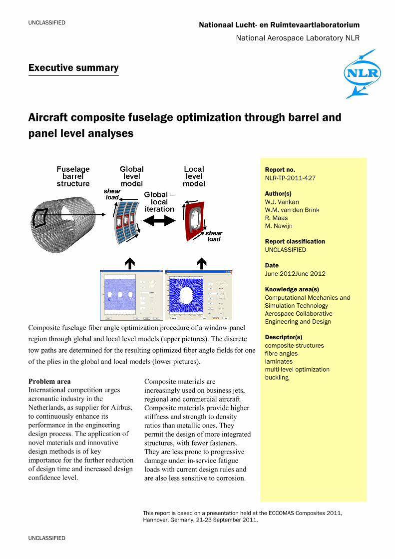
Composite fuselage fiber angle optimization procedure of a window panel region through global and local level models (upper pictures). The discrete tow paths are determined for the resulting optimized fiber angle fields for one of the plies in the global and local models (lower pictures). Problem area International competition urges aeronautic industry in the Netherlands, as supplier for Airbus, to continuously enhance its performance in the engineering design process. The application of novel materials and innovative design methods is of key importance for the further reduction of design time and increased design confidence level.
Composite materials are increasingly used on business jets, regional and commercial aircraft. Composite materials provide higher stiffness and strength to density ratios than metallic ones. They permit the design of more integrated structures, with fewer fasteners. They are less prone to progressive damage under in-service fatigue loads with current design rules and are also less sensitive to corrosion.

UNCLASSIFIED
UNCLASSIFIED
Aircraft composite fuselage optimization through barrel and panel level analyses
Nationaal Lucht- en Ruimtevaartlaboratorium, National Aerospace Laboratory NLR Anthony Fokkerweg 2, 1059 CM Amsterdam, P.O. Box 90502, 1006 BM Amsterdam, The Netherlands Telephone +31 88 511 31 13, Fax +31 88 511 32 10, Web site: www.nlr.nl
Therefore, composite solutions can deliver lighter structures with less maintenance. The aim of the MAAXIMUS project (More Affordable Aircraft structure through eXtended, Integrated, & Mature nUmerical Sizing) is to demonstrate the fast development and right-first-time validation of a highly-optimized composite airframe. This will be achieved through co-ordinated developments on a physical platform, to develop and validate the appropriate composite technologies for low weight aircraft, and on a virtual platform, to identify faster and validate earlier the best solutions. Description of work As part of the virtual platform, a multi-level optimization framework is developed for co-ordinated design optimization of composite fuselage panels. This report describes the application of this framework in a design optimization study of a realistic composite airframe structure where local fiber angles in the skin plies are used as
design variables. A basic multi-level optimization scheme is used where models on two levels, of the fuselage side region and of a local window panel, are optimized. In this optimization, shear loading is considered as the dominant load case and buckling is considered as the critical failure mode. Results and conclusions Various 1D and 2D linear and spline-based parameterizations of fiber orientations were developed and applied in the optimization procedure. The results show that for a fixed structural weight a significant increase in mechanical performance of the fuselage side region with optimized fiber angles can be obtained as compared to quasi-isotropic laminate skin. Applicability The multi-level optimization procedure with the spline-based fiber angle parameterizations developed here can be further applied to other composite aircraft structures.
Nationaal Lucht- en Ruimtevaartlaboratorium National Aerospace Laboratory NLR
NLR-TP-2011-427
Aircraft composite fuselage optimization through barrel and panel level analyses
W.J. Vankan, W.M. van den Brink, R. Maas and M. Nawijn
This report is based on a presentation held at the ECCOMAS Composites 2011, Hannover, Germany, 21-23 September 2011.
The contents of this report may be cited on condition that full credit is given to NLR and the authors. This publication has been refereed by the Advisory Committee AEROSPACE VEHICLES. Customer National Aerospace Laboratory NLR Contract number - - - Owner NLR Division NLR Aerospace Vehicles Distribution Unlimited Classification of title Unclassified June 2012 Approved by:
Author
Reviewer Managing department
NLR-TP-2011-427
2
Summary
The recent introduction of advanced fiber placement machines has lead to a dramatic increase of the design freedom for composite airframe structures. Multi-axis placement heads allow for the manufacturing of fiber paths of almost any shape as long as manufacturing requirements are respected. A challenge currently faced by the aerospace industry is that the increase in manufacturing capabilities is not yet fully supported by traditional design optimization tools. This paper presents a design optimization study of a realistic airframe structure where local fiber angles in the skin plies are used as design variables. A basic multi-level optimization scheme is used where models on two levels, of the fuselage side region and of a local window panel, are optimized. A specific 2D spline-based parameterization of fiber orientations was developed to provide a proper balance between efficiency and general applicability. It is shown that for the same structural weight a significant increase in mechanical performance can be obtained as compared to quasi-isotropic layup.
NLR-TP-2011-427
3
Contents
1 Introduction 5
2 The aircraft fuselage design case 7
3 Parametric definitions of fiber orientations 9
4 Global and local level simulation and optimization 12
5 Results 14
6 Conclusions and discussion 18
References 20
NLR-TP-2011-427
4
Abbreviations
E1, E2, E3 Elastic Young’s moduli in 1/2/3 directions EU European Union FP7 7th Framework Programme G12, G13, G23 Elastic shear moduli in 1/2/3 directions GPa Giga Pascal kg kilogram λ buckling load factor MAAXIMUS More Affordable Aircraft structure through
eXtended, Integrated and Mature nUmerical Sizing
mm millimetre N Newton nu Poisson’s ratio Q4 4-node shell element Ti control angle i Ti_j control angles j for ply i t thickness θ Fiber angle θi Fiber angle for ply i
NLR-TP-2011-427
5
1 Introduction
Ongoing developments in materials technologies have enabled the continuous improvement of airframe structures through the introduction of new materials and the related manufacturing processes. For example, composite materials allow for the design of more integrated structures, yielding lighter structures that require less maintenance than the traditional metallic structures [1]. Due to their laminate nature and the wide range of possible fiber reinforcements, composite materials offer a large range of design variables, with a strong dependency on manufacturing [2]. In particular the application of advanced fiber placement manufacturing allows the exploitation of the local structural benefits of fiber reinforced composite materials. For example, load paths can be locally controlled throughout the primary and secondary aircraft structure. Local elastic tailoring of composite laminate properties, like fiber orientation, thickness reductions or local reinforcements, can be integrated into the structure efficiently. As such the resulting fiber placed structures, also referred to as variable stiffness laminate structures, provide load-tailored local stiffness variations within plies over the whole structure [3]. Variable stiffness structures, as opposed to traditional composite structures with straight and parallel fibres in each ply, are seen as a next step in composite development. The variable stiffness as achieved by steering fiber bundles with an automated fiber placement machine allows for controlled manufacturing of plies with detailed local orientation of the fibres. Consequently, the use of many local fiber orientations as design variables yields tremendous design freedom in structural design and optimization studies. On the other hand also many constraints among the local fiber orientations exist that are related to the continuity, width and thickness of the fiber placed tows. Therefore the adequate representation of variables and constraints and the formulation of the structural design optimization problem is the subject of extensive academic research, e.g. by Gürdal and co-workers [4][5][6]. In these studies often various assumptions, reductions and parameterizations are used to deal with the high dimensionality of the design space. For example, the parametric definition of the local fiber orientation, controlled by few parameters is a commonly used approach (e.g. as proposed in [3], [4]). The benefits of variable stiffness structures may be further exploited if the structural design and optimization process adequately deals with the available degrees of freedom. In particular in the case of optimization of large composite structures, such as aircraft fuselages, the design problem involves very many design variables and constraint functions. One approach to deal with such
NLR-TP-2011-427
6
large optimization problems is to decompose the overall problem into multiple smaller optimization problems. These smaller optimization problems typically consider a series of aspects or sub-systems in various levels of detail. This approach is referred to as multi-level optimization [7]. The above mentioned research on variable stiffness structural design optimization was aimed at thorough structural analysis and extensive optimization, but was mostly applied to relatively simple geometrical structures. Good results were achieved on improving the performance of variable stiffness structures compared to conventional lay-ups. The aim in the present study is to consider a more industrially based structure of an aircraft fuselage section and to investigate the maximization of buckling performance by variable stiffness skin design in combination with a multi-level optimization scheme. Moreover, the aim is to take into account manufacturing constraints that are related to fiber angle continuity over the whole structure for each ply. Additional manufacturing constraints related to minimum fiber curvature radius, fiber densities, gaps and overlaps and laminate thickness effects can be incorporated in the approach but are not yet included. In this paper we address the optimization of an aircraft fuselage structure, where the analysis is focused on the behaviour under shear loading of the side region of the fuselage including window cut outs and local reinforcements. The global level optimization aims for maximum buckling performance, where the fiber angles of the skin plies are used as design variables and structural weight and manufacturing constraints are taken into account. In order to specifically optimize fiber orientations in the reinforcement layers around the window cut outs, also local level analysis and optimization is performed on a more detailed model of the window panel area. In this way the multi-level optimization intends to efficiently incorporate the design variables that are related to the different model levels. This study is part of ongoing work in the EU FP7 research project MAAXIMUS [8]. The focus in the present paper is on the application of effective parametric representation of fiber orientations for design optimization of a realistic industrial structure that includes complex geometries, stiffened structures and multiple materials. Further developments to account for structural sizing and to include additional constraints, e.g. for failure, are ongoing.
NLR-TP-2011-427
7
2 The aircraft fuselage design case
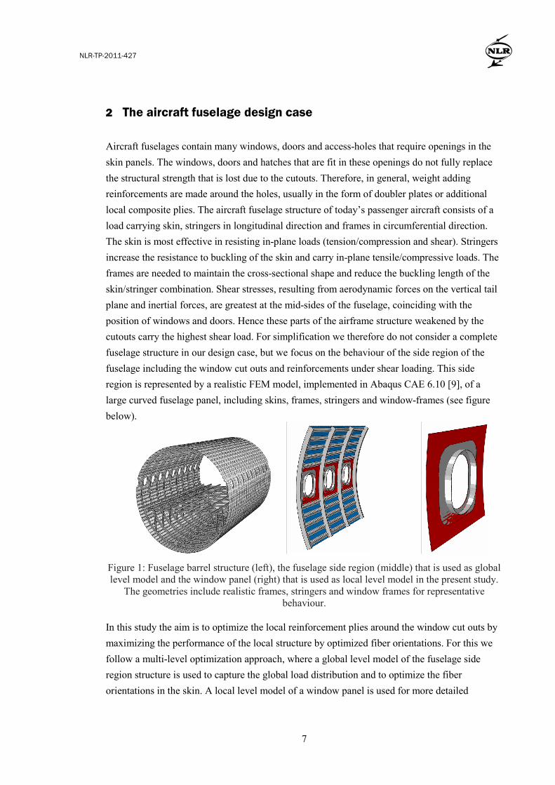
Aircraft fuselages contain many windows, doors and access-holes that require openings in the skin panels. The windows, doors and hatches that are fit in these openings do not fully replace the structural strength that is lost due to the cutouts. Therefore, in general, weight adding reinforcements are made around the holes, usually in the form of doubler plates or additional local composite plies. The aircraft fuselage structure of today’s passenger aircraft consists of a load carrying skin, stringers in longitudinal direction and frames in circumferential direction. The skin is most effective in resisting in-plane loads (tension/compression and shear). Stringers increase the resistance to buckling of the skin and carry in-plane tensile/compressive loads. The frames are needed to maintain the cross-sectional shape and reduce the buckling length of the skin/stringer combination. Shear stresses, resulting from aerodynamic forces on the vertical tail plane and inertial forces, are greatest at the mid-sides of the fuselage, coinciding with the position of windows and doors. Hence these parts of the airframe structure weakened by the cutouts carry the highest shear load. For simplification we therefore do not consider a complete fuselage structure in our design case, but we focus on the behaviour of the side region of the fuselage including the window cut outs and reinforcements under shear loading. This side region is represented by a realistic FEM model, implemented in Abaqus CAE 6.10 [9], of a large curved fuselage panel, including skins, frames, stringers and window-frames (see figure below).
Figure 1: Fuselage barrel structure (left), the fuselage side region (middle) that is used as global level model and the window panel (right) that is used as local level model in the present study.
The geometries include realistic frames, stringers and window frames for representative behaviour.
In this study the aim is to optimize the local reinforcement plies around the window cut outs by maximizing the performance of the local structure by optimized fiber orientations. For this we follow a multi-level optimization approach, where a global level model of the fuselage side region structure is used to capture the global load distribution and to optimize the fiber orientations in the skin. A local level model of a window panel is used for more detailed

NLR-TP-2011-427
8
optimization of fiber orientations in the local reinforcement plies. The fuselage geometry is based on the reference generic fuselage model as defined in MAAXIMUS. The global level model geometry consists of three frame sections with a total length of 2012 mm. The curvature radius of the fuselage skin is 2150 mm. The present study considers only a shear load with an assumed limit load value of 200 N/mm. As shown in the figure above, the global level model is composed from 4 different parts: the skin, stringers, frames and window frames. All parts are modelled with Q4 shell elements and their instances are fixed together with tie constraints. The parts are meshed with an element size of approximately 15 mm such that the skin pockets between the stringers are spanning 5 elements, which is sufficient to represent local skin buckling effects. This results in a total of approximately 16k elements for the model. The following boundary conditions are used in the global panel level analyses:
• All 3 rotations of all skin edges (straight and curved edges) are suppressed; • All radial displacements of all skin edges (straight and curved edges) are suppressed; • All 3 rotations of all frames and stringer end-cross-sections (i.e. near the straight and
curved edges of the panel) are suppressed; • All radial displacements of all frames and stringer end-cross-sections (i.e. near the
straight and curved edges of the panel) are suppressed; • Tangential and axial displacements (i.e. in stringer and frame direction, resp.) of one
skin corner point is suppressed to avoid rigid body motion.
The local level window panel model, also shown in the figure above, consists of only 2 parts, the skin (which includes the local reinforcement plies) and the window frame, which are fixed together with tie constraints. A similar meshing as in the global panel model is applied with an element size of approximately 5 mm resulting here in a total of approximately 1.6k elements for the local level model. For simplicity, similar boundary conditions on the skin edges as for the global panel model are used. The material properties and composite laminate designs that were used are also based on the MAAXIMUS reference generic fuselage model definition. For the reference simulations within this research the following laminate designs and mechanical properties are used:
• Composite lamina: E1=157GPa, E2=8.5GPa, G12=G13=G23=4.2GPa, nu=0.35, t=0.125mm.
• Aluminium - isotropic: E=72GPa, nu=0.33. • Skin: 13 ply composite layup: [-45/45/90/0/-45/45/0/45/-45/0/90/45/-45] • Window local reinforcement plies: 11 ply composite layup: [-45/45/90/0/-45/45/0/45/-
45/0/90/45/-45]
NLR-TP-2011-427
9
• Stringers: 24 ply composite layup: [-45/45/0/0/45/90/-45/0/-45/90/45/0]s • Frames: Aluminium, t=3mm. • Window frames: Aluminium, t=3mm. • Total mass of global level panel: 38kg.
3 Parametric definitions of fiber orientations
For a well-defined optimization a suitable method for defining the fiber paths is needed. Ideally such a definition allows for high freedom of the locally defined fiber orientations, but requires only few input parameters. In this design case we investigated various parametric definitions, in order to obtain the most suitable fiber orientation representation with sufficient freedom but not too many parameters. Initially, a one dimensional piecewise linear variation of the fiber angles (θ(x,T1,...,Tn)) over the panel was used, which is based on the “shifted path” parametric fiber angle definition as proposed in [3]. Here x is the one dimensional spatial co-ordinate, and T1,...,Tn are n control angles that are used as parameters; we used n=2. This parameterization was applied in an initial global level model optimization run, where the fiber angles of several plies in the fuselage skin were replaced by the parametric local fiber angles (±θ) as defined in each finite element. The results from this run showed only little improvement in buckling resistance, which might be due to the low design freedom of the linear angle variation. To allow for more freedom in the fiber orientations, also a one dimensional cubic-spline-based variation of the fiber angles over the panel was used. Similar to the linear variation, the fiber angles are defined as a one dimensional function of the circumferential position in the skin, but now varied non-linearly with five instead of two control angles (n=5). To allow for even more freedom in the fiber angle definition we also implemented a two dimensional variation of the fiber angles (θ(x,y,T1,...,Tn)) based on cubic-spline surface interpolation, where (x,y) are the two dimensional spatial co-ordinates and 12 control angles T1,...,Tn are used as parameters (n=12). Note that all three methods only represent the local fiber orientation, i.e. the actual tow path has to be derived from this vector field. An illustration of this will be given in a later section of this paper. The figure below shows examples of the resulting fiber angles defined by the three different methods in one of the skin plies of the global panel model.
NLR-TP-2011-427
10
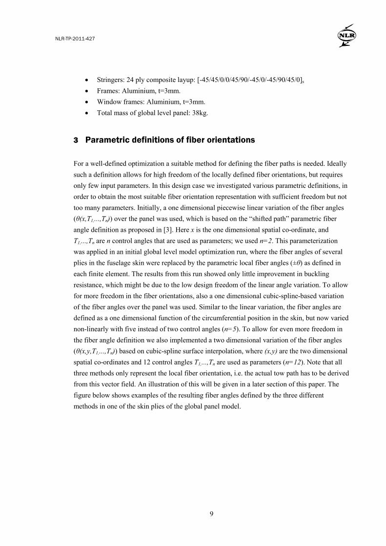
Figure 2: Skin ply angles in the global panel model as defined by the three methods: 1-D linear variation (left graph), 1-D spline-based variation (middle graph) and 2-D spline-based variation
(right graph). The ply angle is defined as the angle between the local fiber direction and the axial direction (horizontal in the graphs) and indicated in the graphs by colour coding where blue represents low values (axial direction) and red represents high values (circumferential
direction).
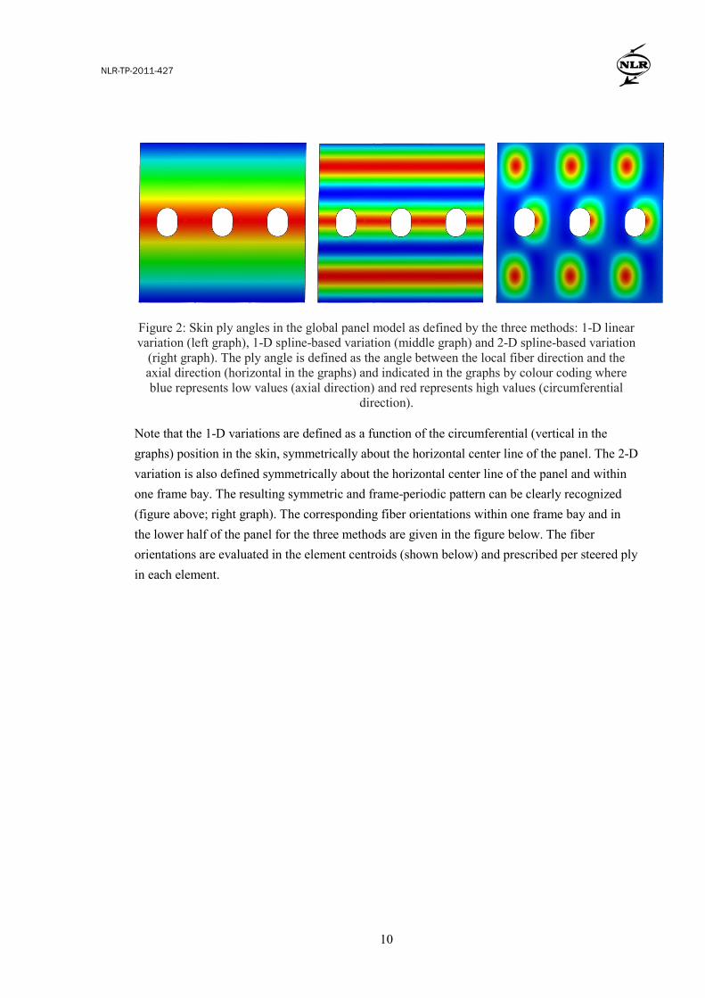
Note that the 1-D variations are defined as a function of the circumferential (vertical in the graphs) position in the skin, symmetrically about the horizontal center line of the panel. The 2-D variation is also defined symmetrically about the horizontal center line of the panel and within one frame bay. The resulting symmetric and frame-periodic pattern can be clearly recognized (figure above; right graph). The corresponding fiber orientations within one frame bay and in the lower half of the panel for the three methods are given in the figure below. The fiber orientations are evaluated in the element centroids (shown below) and prescribed per steered ply in each element.
NLR-TP-2011-427
11
Figure 3: Detailed view of the fiber orientations within one frame bay and in the lower two-thirds of the global panel model for the three methods: 1-D linear variation (left graph), 1-D
spline-based variation (middle graph) and 2-D spline-based variation (right graph).
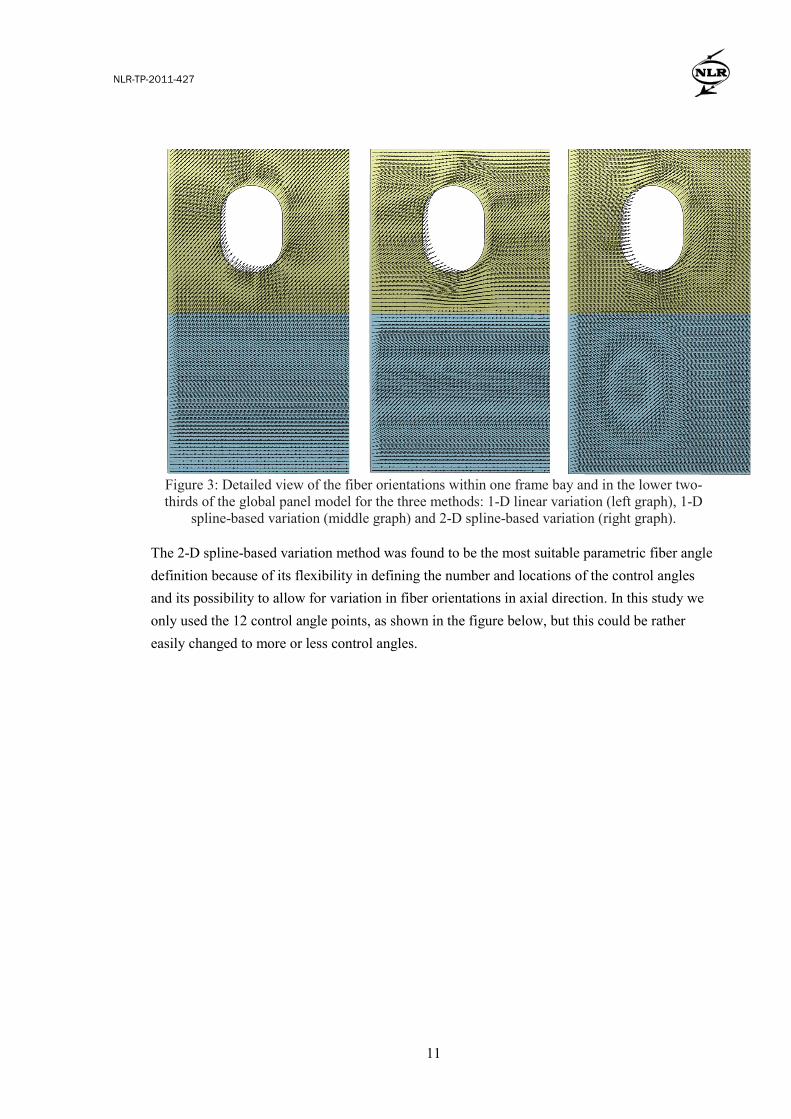
The 2-D spline-based variation method was found to be the most suitable parametric fiber angle definition because of its flexibility in defining the number and locations of the control angles and its possibility to allow for variation in fiber orientations in axial direction. In this study we only used the 12 control angle points, as shown in the figure below, but this could be rather easily changed to more or less control angles.
NLR-TP-2011-427
12
Figure 4: Illustration of the 2-D spline-based variation method as implemented for the global
panel model, with the symmetric and periodic pattern and the locations of the 12 control angle points indicated. An example of a resulting fiber angle distribution is also shown (small black
arrows).
Because of the above mentioned advantages the 2-D spline-based variation method was further used in the optimizations of both the global level panel model and the local level window panel model. For practical implementation reasons the same spatial distribution of control angle points as for the global panel model (i.e. as shown in figure above) was used in the window panel model. As a result, the main effective parameters for the window panel model were the control angles (T3,T4,T7,T8,T11,T12). Note that the frame-periodic pattern of the control angle points that was used accommodates manufacturing constraints such that fiber angle continuity over adjacent frame bays is ensured by the parametric angle definition. In this study only such rather basic manufacturing constraints are taken into account in the parametric fiber angle definitions and hence considered in the optimization. The resulting optimal design, however, will be further evaluated on fiber placement manufacturing aspects such as width of placed tows, minimal radius, fiber placement machine range etc. 4 Global and local level simulation and optimization
In this study we apply a basic multi-level optimization procedure to the global and local panel models described above. On the global level we maximize the first buckling load by variation of the fiber orientations in the global skin plies. Three independent fiber angles (θ1, θ2, θ3) defined by the 2-D spline-based variation are used, yielding 36 parameters (control angles T1_1,...,Tn_m ;

NLR-TP-2011-427
13
n=12, m=3) in total. These fiber angles are assigned to the skin plies in the following layup: [θ1/-θ1/θ3-45/θ3+45/θ2/-θ2/θ3+45/-θ2/θ2/θ3+45/θ3-45/-θ1/θ1]. The resulting optimized global skin fiber angles are then adopted in the skin plies of the local level window panel model. Then the first buckling load of the local level window panel model is maximized by variation of the fiber orientations in the local reinforcement plies. Here we use two independent fiber angles (θ4,θ5) also defined by the 2-D spline-based variation, yielding 24 parameters in total (the control angles T1_4,...,Tn_m ; n=12, m=5). These fiber angles are assigned to the local reinforcement plies according to: [θ4/-θ4/90/0/θ5/-θ5/0/-θ5/θ5/0/90/-θ4/θ4]. The resulting local reinforcement plies fiber angles are then adopted in the global level panel model, where the global level buckling load optimization is repeated. It should be noted that in both the global and local level panel models, the total layup around the windows is: [θ1/-θ1/θ3-45/θ3+45/θ2/-θ2/θ3+45/-θ2/θ2/θ3+45/θ3-45/-θ1/θ1 / θ4/-θ4/90/0/θ5/-θ5/0/-θ5/θ5/0/90/-θ4/θ4]. Also note that with these layup definitions, the reference layups are represented by setting all fiber angles θi to 45o, in the whole geometry, which is achieved by setting all control angles to 45o (Ti_j = 45o ; i=1,...,12 , j=1,...,5). The bounds for each of the parameters (control angles) were set to 0o and 90o (0o ≤ Ti_j ≤ 90o ; i=1,...,12 , j=1,...,5). A combination of general purpose optimization algorithms implemented in python libraries [10] were used in the optimizations.
Figure 5: Illustration of the global-local optimization scheme: a similar optimization loop using Abaqus Lanczos analyses is executed for both the global and local level models.
The iteration of this global and local level optimization leads to a final optimized global panel model with fiber angles in the skin and reinforcement plies defined according to the 60
NLR-TP-2011-427
14
optimized parameters. In the present study a reasonably converged maximum buckling load on the global level was found after 3 global-local iterations, requiring approximately in total 5000 function evaluations of the local level window panel model and 3500 function evaluations of the global level panel model. On the global level the buckling load factor (λ) was improved from 0.827 for the reference configuration to 0.928 for the final global and local optimized configuration, i.e. about 12% improvement. 5 Results
The optimizations on the global and local levels both resulted in improved buckling load factors. The optimized local reinforcement plies from the local model are incorporated in the global model, contributing to the overall optimized panel buckling behaviour. This is illustrated in the figure below, showing the improvement of the buckling modes of the optimized panel as compared to the reference panel. In the reference panel, having conventional QI laminate lay-ups, a low first buckling mode in window region (λ=0.836) and a high buckling mode in skin bay region (λ=1.175). This indicates that high buckling reserve factors remain in the stiffened regions. For the optimized laminate configuration (i.e., with the variable stiffness laminate lay ups), the buckling modes in the window panel region (λ=0.928) and in the stiffened panel region (λ=0.936) converge to higher total buckling resistance. The first skin mode (in the un-stiffened window region) now occurs already as the 3rd mode instead of the 13th mode.

NLR-TP-2011-427
15
Figure 6: Illustration of the first buckling modes occurring in the un-stiffened window region (left) and in the stiffened panel region (right), for the global panel model in the reference
configuration with QI laminates (upper) and for the optimized configuration with variable stiffness laminate lay ups (lower).
From the buckling modes results it seems that the buckling load improvement of about 12% is due to a (slightly) decreased internal shear loading in the central window panel achieved through the optimized fiber orientations in the global skin plies, and a (slightly) increase of buckling resistance in the window panel achieved through the optimized fiber orientations in the local reinforcement plies. In the figure below we show the first buckling modes of the final optimized global and local models, clearly showing the window frame buckling as the first mode on both levels, which supports the approach followed here to specifically consider the window frame buckling in the local level optimization. The fiber orientations in the final optimized global and local models are defined in the element centroids, as illustrated for the first ply of both the global and local panel models (i.e. θ1 and θ4) in the figure below.

NLR-TP-2011-427
16
Figure 7: Illustration of the first buckling modes (upper graphs) and fiber orientations for the
first ply (lower graphs) of the final optimized global (left graphs) and local (right graphs) models.
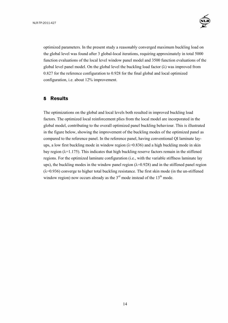
As already mentioned, the optimizations only yield the local fiber orientations in the plies and the actual tow paths have to be derived from these vector fields. In the derivation of these tow paths further fiber placement manufacturing aspects, such as width of placed tows, minimal radius, fiber placement machine range etc., are taken into account. At NLR several procedures have been developed for this [11] and a software tool was developed for determination of tow paths, taking into account these manufacturing settings (see Figure 8 below).
NLR-TP-2011-427
17
Figure 8: Illustration of the fiber placement software tool.
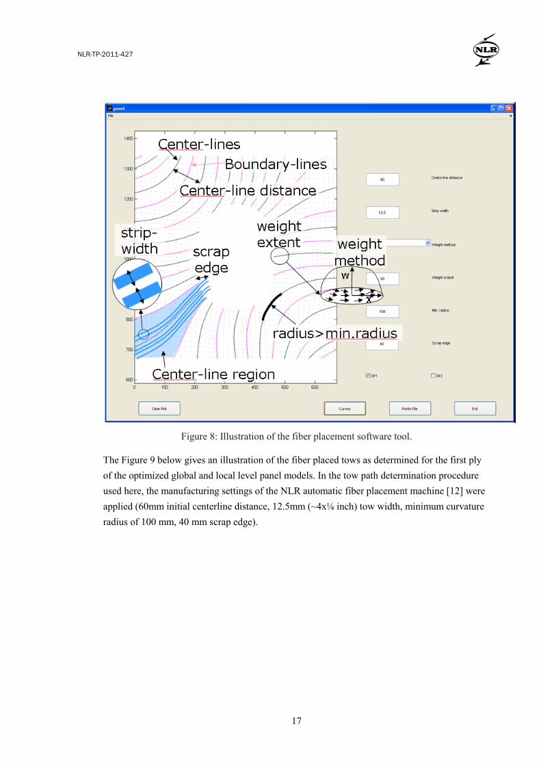
The Figure 9 below gives an illustration of the fiber placed tows as determined for the first ply of the optimized global and local level panel models. In the tow path determination procedure used here, the manufacturing settings of the NLR automatic fiber placement machine [12] were applied (60mm initial centerline distance, 12.5mm (~4x⅛ inch) tow width, minimum curvature radius of 100 mm, 40 mm scrap edge).
NLR-TP-2011-427
18
Figure 9: Illustration of the fiber placed tows as determined for the first ply of the optimized
global (left) and local (right) level panel models.
It should be noted that the fiber placed tows are determined after completion of the global-local optimization loop. Hence the manufacturing aspects that were covered in this determination were not accounted for in the optimization and might lead to sub-optimal or infeasible designs. To avoid that, the tow path determination tool should be included in the global-local optimization loop, see Figure 10 below. This was not considered in the present study and may be addressed in future investigations. 6 Conclusions and discussion
In this paper we present initial results of a multi-level analysis and optimization study of a large structural design case of a side region of a fuselage under shear loading involving local elastic tailoring of composite laminate properties. Local fiber orientations are considered as the design variables, intended for application in advanced fiber placement manufacturing. Some basic manufacturing constraints were accounted for in the optimization and more detailed manufacturing aspects were shown to be handled in the further processing of the optimized design. The optimization covered both global and local level fiber angle optimizations based on various parameterization techniques. It was shown that structural performance benefit can be obtained from elastic tailoring when it is used to control the load paths in the structure. For simplicity, the fiber placed tows are determined after completion of the global-local optimization loop. Instead, to properly cover the manufacturing aspects of the structure, the tow path determination tool should be included in the global-local optimization loop, see Figure 10 below.

NLR-TP-2011-427
19
Figure 10: Illustration of the global-local optimization scheme where the tow path determination
is included, yielding additional manufacturing constraints in the optimization loop.
The optimized panel in the present study yields an improvement of about 12% of the buckling load factor of the first mode of the global panel model as compared to the reference configuration. However, the first mode shape shows a buckling of the central window frame for both the reference and the optimized configurations. The buckling improvement is possibly due to a (slightly) decreased internal shear loading in the central window panel achieved through the optimized fiber orientations in the global skin plies, and a (slightly) increase of buckling resistance in the window panel achieved through the optimized fiber orientations in the local reinforcement plies. If the first buckling mode would be a local mode in the skin of one of the stringers bays, much more improvement of buckling performance could be achieved by the fiber orientation optimization. Instead of the performance optimization shown in this study, another interesting approach would be to consider sizing optimization. The gains in buckling performance should be translated to gains in weight typically by decreasing the skin thickness. This would require, however, ply reductions and layup changes in the skin and reinforcements, which was out of scope for the present study but is intended to be considered in ongoing work in this area with the MAAXIMUS project. Acknowledgements The research leading to these results has received funding from the European Community’s Seventh Framework Programme FP7/2007-2013 under grant agreement n°213371 (MAAXIMUS, www.maaximus.eu).
NLR-TP-2011-427
20
References
[1] Design and analysis of composite structures: with applications to aerospace structures, C. Kasapoglou, Wiley, 2010.
[2] Fundamentals of composites manufacturing: materials, methods and applications, A.B. Strong, Dearborn, Mich.: Society of Manufacturing Engineers, 2008.
[3] In-plane response of laminates with spatially varying fibre orientations: Variable stiffness concept, Z. Gürdal and R. Olmedo, AIAA J., 31(4), pp. 751–758, 1993.
[4] Design tailoring for pressure pillowing using tow-placed steered fibres, A. Alhajahmad, M.M. Abdalla and Z. Gürdal, J. Aircraft, 45(2), pp. 630-640, 2008.
[5] Design of variable stiffness laminates using lamination parameters, S. Setoodeh, M.M. Abdalla and Z. Gürdal, Composites, Part B: Engineering, 37, pp. 301-309, 2006.
[6] Optimization of Course Locations in Fiber-Placed Panels for General Fiber Angle Distributions, A.W. Blom, M.M. Abdalla and Z. Gürdal, J. Compos. Sc. Technol., 70(4), pp. 564-570, 2010.
[7] Optimization of Coupled Systems: A Critical Overview of Approaches, R.J. Balling and J. Sobieszczanski-Sobieski, Proc. AIAA/NASA/USAF/ISSMO 5th Symposium on Multidisciplinary Analysis and Optimization, pp. 697 - 707, Panama City, Florida, USA, September 1994.
[8] http://www.maaximus.eu/ . [9] http://www.simulia.com/products/abaqus_fea.html . [10] http://openopt.org/ . [11] Development of a cost effective composite wing-box for small Aircraft, R. Klomp-de Boer,
SAMPE Conf., Seattle, USA, May 2010 (NLR-TP-2010-047, http://www.nlr.nl/?id=15546 ). [12] http://www.nlr.nl/smartsite.dws?id=8917 .