aircraft general knowledge - yorkshire...
TRANSCRIPT

Aircraft General Knowledge

Different types of rotor systems but first of all some terminology…
Feathering – twisting of the blade in order to change 'pitch'. Flapping – up and down movement of the blade as it gains or loses lift. Lead-Lagging (dragging) – a slight fore and aft movement of the blade to compensate for Coriolis (or ice skating) effect.

Fully Articulated Rotor System. A fully articulated rotor system usually consists of three or more rotor blades. The blades are allowed to flap, feather, and lead or lag independently of each other. Each rotor blade is attached to the rotor hub by a horizontal hinge, called the flapping hinge, which permits the blades to flap up and down. Each blade can move up and down independently of the others. The flapping hinge may be located at varying distances from the rotor hub, and there may be more than one. The position is chosen by each manufacturer, primarily with regard to stability and control. Each rotor blade is also attached to the hub by a vertical hinge, called a drag or lag hinge, that permits each blade, independently of the others, to move back and forth in the plane of the rotor disc. Dampers are normally incorporated in the design of this type of rotor system to prevent excessive motion about the drag hinge. The purpose of the drag hinge and dampers is to absorb the acceleration and deceleration of the rotor blades. The blades of a fully articulated rotor can also be feathered, or rotated about their spanwise axis. To put it more simply, feathering means the changing of the pitch angle of the rotor blades.


Semi-Rigid Rotor System. A semi-rigid main rotor is always a 2 bladed rotor system. It gets its name from the fact that it does not have a lead-lag hinge, the way a fully articulated rotor system does. The rotor system can be said to be rigid in-plane, because the blades are not free to lead and lag, but they are not rigid in the flapping plane (through the use of a teeter hinge). Therefore the rotor is not rigid, but not fully articulated either, so we call it semi-rigid. The rotor systems we will look at here are 2 bladed teetering systems. The Robinson and the Bell teetering system differ because the Robinson includes coning hinges in addition to the teeter hinge, while the Bell system simply cones by bending the blades.

Teeter Hinge The dark blue arrow is pointing to the teeter hinge. This central hinge allows the entire rotor head to tilt left and right in order to allow the blades to flap. When one blade flaps up, the other flaps down. The entire mechanical arrangement works like a child's see-saw Coning Hinge The light blue arrows point to the two coning hinges. These hinges allow each blade to move up and down independently of the other blade. During times of high lift, or low RPM, the blades will be coned quite high, while during low lift or high RPM, the blades will tend to be lower.The holes in the rotor head above the coning hinges serve no purpose except that they may be used to hoist the rotor system.

The design of the Bell 206 rotor head is not that different from that of the Robinson. Note that in this picture, there are no light blue arrows, because the 206 head does not include coning hinges. Instead, the rotor head is designed with a pre-cone angle to the blade retention system, and other coning forces are simply dealt with by bending of the blades (which must be built stronger to deal with the extra stress)

Rigid Rotor System. The rigid rotor system is mechanically simple, but structurally complex because operating loads must be absorbed in bending rather than through hinges. In this system, the blade roots are rigidly attached to the rotor hub. Rigid rotor systems tend to behave like fully articulated systems through aerodynamics, but lack flapping or lead/lag hinges. Instead, the blades accommodate these motions by bending. They cannot flap or lead/lag, but they can be feathered. As advancements in helicopter aerodynamics and materials continue to improve, rigid rotor systems may become more common because the system is fundamentally easier to design and offers the best properties of both semirigid and fully articulated systems.

The rigid rotor system is very responsive and is usually not susceptible to mast bumping like the semirigid or articulated systems because the rotor hubs are mounted solid to the main rotor mast. This allows the rotor and fuselage to move together as one entity and eliminates much of the oscillation usually present in the other rotor systems. Other advantages of the rigid rotor include a reduction in the weight and drag of the rotor hub and a larger flapping arm, which significantly reduces control inputs. Without the complex hinges, the rotor system becomes much more reliable and easier to maintain than the other rotor configurations. A disadvantage of this system is the quality of ride in turbulent or gusty air. Because there are no hinges to help absorb the larger loads, vibrations are felt in the cabin much more than with other rotor head designs.


The Swashplate
A ball joint is mounted on the rotor mast. This ball joint can move freely up and down the shaft.
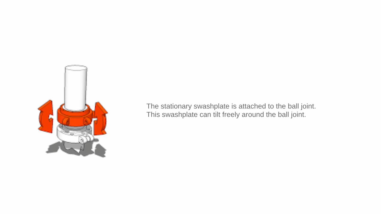
The stationary swashplate is attached to the ball joint. This swashplate can tilt freely around the ball joint.

To keep the stationary swashplate from rotating with the rotor, a scissor mechanism is added.
The swashplate can move freely up and down, and can freely tilt in any direction, but can't rotate around the mast.

Three control rods are attached to the lower swashplate using ball joints. These rods are essential for being able to steer the helicopter. By independently pushing or pulling the rods, the height and tilt of the lower swashplate will change, which in turn changes the blade pitch, and the direction of the helicopter.

A second swashplate is added on top of the lower swashplate. The upper swashplate can rotate independently from the lower swashplate.

A second scissor mechanism is added. This scissor is nearly identical to the one that connects the lower swashplate to the fuselage. The only difference is that this one connects the upper swashplate to the rotor mast. This means that the upper swashplate will always follow the rotor blades.

Tail Rotor Systems

Conventional Tail Rotor Advantages. Effective Anti-torque System. Relatively cheap production
Disadvantages Noisy Dangerous for people on the ground.

Advantages. Quiter Safer Less vibration due to enclosure of blade tips
Disadvantages Increased weight Greater production cost
Fenestron
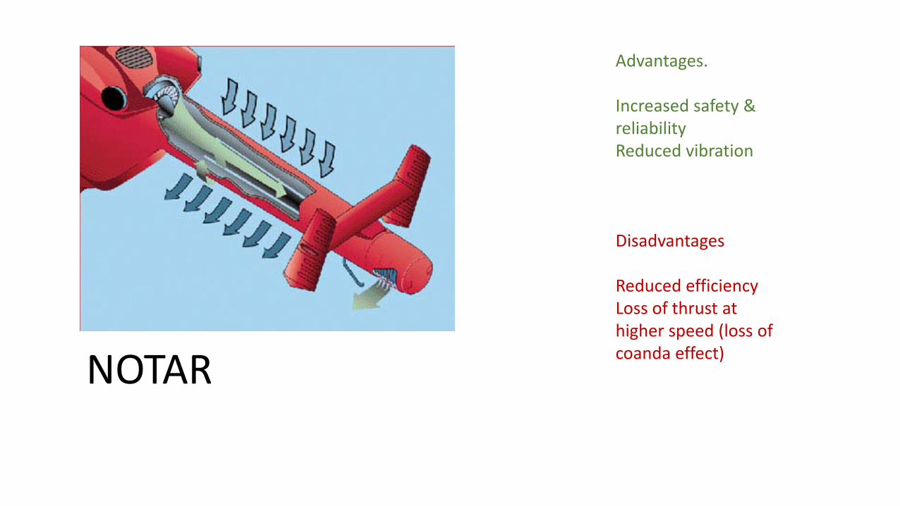
Advantages. Increased safety & reliability Reduced vibration
Disadvantages Reduced efficiency Loss of thrust at higher speed (loss of coanda effect) NOTAR

Piston Engine

Crankshaft – Converts reciprocating motion into rotary motion.

Camshaft

Magnetos
Aircraft piston engines do not need a battery for ignition, instead they generate power for the spark plug using a magneto.
The idea behind any ignition system is to generate an extremely high voltage – in the order of 20,000 volts -- at exactly the right time. The voltage causes a spark to jump across the spark plug's gap, and the
spark ignites the fuel in the engine.

These use a strong magnet rotating inside a coil. The magnetic field generates a voltage in the coil which is transformed to a higher voltage by a secondary coil with much more windings than the primary coil. A breaker contact in the primary coil circuit interrupts the flowing current and this interruption causes the magnetic field to collapse thereby generating a very high peak voltage in the secondary coil. This peak voltage is then conducted to the correct spark plugs by the distributor and high voltage leads.

Distributor The distributor is also part of the magneto. Its function is to guide the high energy voltage to the correct spark plug through one of the high tension leads. As each cylinder fires every two revolutions of the crankshaft, the rotor in the distributor must therefore rotate at half the crankshaft speed.

Impulse coupling During starting of the engine, the crankshaft rotates very slowly (around 120 RPM) and the magnetos at 60 RPM. Generated voltage is very low at that point. The ignition timing is normally fixed at 25° Before TDC, which is too early at low RPM. Should a cylinder fire it would probably cause a violent kickback (rotation in the wrong direction) damaging the starter. A device called an impulse coupling is used to slow down ignition timing to almost TDC and accelerate the magnet (with a coiled spring) in the magneto to increase voltage and help ignite the mixture at TDC. When the engine fires and its RPM rises the timing is set back to 25° for normal operation (between 500 and 2700 RPM). The moment the engine fires and runs idle the impulse coupling detaches and timing is reset to 25° BTDC On some engines a vibrating system is used to create a shower of sparks with the left magneto when starting during these low RPM operations.

Ignition Switch
1.Off - Both magneto p-leads are connected to electrical ground. This disables both magnetos, no spark is produced. 2.Right - The left magneto p-lead is grounded, and the right is open. This disables the left magneto and enables the right magneto only. 3.Left - The right magneto p-lead is grounded, and the left is open. This disables the right magneto and enables the left magneto only. 4.Both - This is the normal operating configuration, both p-leads are open, enabling both magnetos. 5.Start - The pinion gear on the starter motor is engaged with the flywheel and the starter motor runs to turn the engine over. In most cases, only the left magneto is active (the right p-lead is grounded) due to timing differences between the magnetos at low RPMs.
Your P lead is the wire connecting the starter switch to your magneto’s primary windings, thus P lead. Their primary purpose is to ground the magnetos to avoid accidental starts.

Typical R44 Electrical System. Includes either a 14V Alternator with a 12V Battery or a 28V Alternator and 24V battery (for later models). Ammeter will indicate slightly right to show current flowing through battery under normal working conditions. The battery switch controls the battery relay which disconnects the battery from the electrical system. A wire protected by a fuse near the battery bypasses the battery relay to allow both tachometers and the clock to continue to receive battery power with the battery switch off.
An ammeter indicates current to the battery. An ALT caution light or ammeter discharge indication in flight indicates low voltage and possible alternator failure. Turn off nonessential electrical equipment and switch alternator off then back on after one second to reset alternator control unit. If ALT light stays on or ammeter still indicates discharge, land as soon as practical. The battery will last approximately 30 minutes.
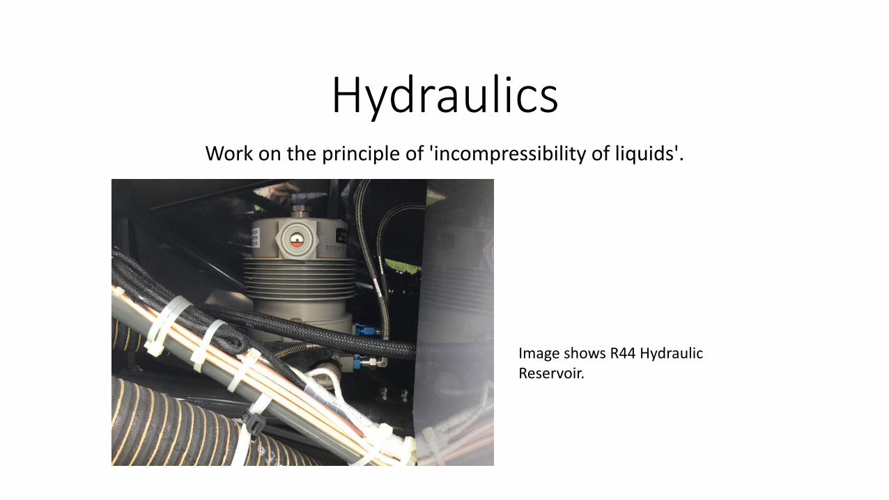
Hydraulics Work on the principle of 'incompressibility of liquids'.
Image shows R44 Hydraulic Reservoir.

Pascal's law is the basis of hydraulic drive systems. As the pressure in the system is the same, the force that the fluid gives to the surroundings is therefore equal to pressure × area. In such a way, a small piston feels a small force and a large piston feels a large force.
Force = Pressure x Area Hydraulic pressure is provided by a pump, usually driven by the engine or gearbox.

The hydraulic system consists of a pump, three servos, a reservoir, and interconnecting lines. The working fluid is MIL-H-5606 and normal operating pressure is 450 to 500 psi. The pump is mounted on and driven by the main rotor gearbox so that hydraulic pressure is maintained in the event of an engine failure. A servo is connected to each of the three push-pull tubes that support the main rotor swashplate. The reservoir is mounted on the steel tube frame behind the main rotor gearbox and includes a filter, pressure relief valve, and pilot-controlled pressure shut-off valve.
R44 System

Carburettor Icing

A temperature drop through the Venturi causes moisture from the air to freeze. A build up of ice further develops the Venturi and worsens the situation. Moisture is almost always present, in fact, warmer air has the ability to hold more moisture. Carburettor Icing can therefore be encountered in outside air temperatures up to 32 degrees Celsius. Any day in the U.K. is a Carb Icing day. Use of Carb Heat takes hot air from a scoop around the exhaust and directs this into the engine.

Pitot-Static Instruments Altimeter Vertical Speed Indicator Airspeed Indicator

Altimeter

Vertical Speed Indicator

Airspeed Indicator


Magnetic Compass It is the only thing we have to determine direction of flight.

UNOS (Undershoot North Overshoot South) ONUS (Overshoot North Undershoot South)
In a coordinated turn, the compass, like the occupants of the airplane, feels an effective gravitational force down the vertical axis of the airplane, which banks the compass card with the airplane, out of the horizontal. Suppose for instance, an airplane (in the Northern Hemisphere) is in a coordinated turn, as illustrated, which depicts the situation where the airplane is currently heading North or South. In each case, because of the dip, the north seeking end of the compass swings downward, so that the compass no longer indicates North or South respectively.

In aircraft instruments, gyros are used in attitude, compass and turn coordinators. These instruments contain a wheel or rotor rotating at a high RPM which gives it two important properties: rigidity and precession. The rotor or gyro can be electrically or vacuum / pressure driven by a pump on the engine.
Gyroscopes

Types of gyros and uses in aircraft instruments. •Rate gyro can move in one plane (not the plane of rotation) and the movement in the third plane is used to measure the precession. You will see this type of gyro in a Turn Coordinator or Turn and Bank indicator (old models). •Tied gyro moves in all three planes but kept in one plane by an outside force, usually air jets in case of the Direction Indicator (Gyro compass) •Earth gyro has freedom of movement in all three planes but is held in one plane by Earths gravity. You will find this gyro in an Attitude Indicator. •Space Gyro moves in all three planes and is stabilized to a fixed point in space. You will apparently see this gyro move due to the Earths rotation while in fact its not moving at all, space wise.


There are two main oil types used in aircraft engines: mineral oil and ashless dispersant (AD) oil. Both types are made of mineral oil - a refined, petroleum based oil. However, AD oils have added chemicals (additives), which collect debris inside the engine and carry them to the oil filter.
Oil
