aircraft systems - acceuilcaacongo.com/corporate/co_at_fcom/pdf_n_fcom_82u_tf_n_eu__2… ·...
TRANSCRIPT

AIRCRAFT SYSTEMS
POWER PLANT

Intentionally left blank

A318/A319/A320/A321FLIGHT CREW
OPERATING MANUAL
AIRCRAFT SYSTEMSPOWER PLANT
PRELIMINARY PAGES - TABLE OF CONTENTS
82U A318/A319/A320/A321 FLEET DSC-70-PLP-TOC P 1/4FCOM 06 MAR 14
DSC-70-10 EngineGENERAL................................................................................................................................................................ ADESCRIPTION.........................................................................................................................................................B
DSC-70-20 FadecGENERAL................................................................................................................................................................ AARCHITECTURE..................................................................................................................................................... BFUNCTIONS ...........................................................................................................................................................CPower Supply...........................................................................................................................................................D
DSC-70-30 Thrust Control System (CFM+PW)DSC-70-30-10 General
General.....................................................................................................................................................................A
DSC-70-30-20 Thrust LeversTHRUST LEVERS................................................................................................................................................... A
DSC-70-30-30 Thrust Rating LimitTHRUST RATING LIMIT......................................................................................................................................... A
DSC-70-30-40 Thrust ControlManual Mode........................................................................................................................................................... AAUTOMATIC MODE................................................................................................................................................ BAutomatic Mode.......................................................................................................................................................CTHRUST CONTROL................................................................................................................................................D
DSC-70-40 Fuel System (CFM)1 DSC-70-40-10 General
General.....................................................................................................................................................................A
DSC-70-40-20 Fuel Pump UnitFUEL PUMP UNIT...................................................................................................................................................A
DSC-70-40-30 Shut-Off ValvesSHUT-OFF VALVES................................................................................................................................................A
DSC-70-40-40 Hydromechanical UnitGENERAL................................................................................................................................................................ AFUEL FLOW ...........................................................................................................................................................BOVERSPEED GOVERNOR SYSTEM.................................................................................................................... CIDLE CONTROL...................................................................................................................................................... DFUEL HYDRAULIC SIGNALS ................................................................................................................................E
Continued on the following page

A318/A319/A320/A321FLIGHT CREW
OPERATING MANUAL
AIRCRAFT SYSTEMSPOWER PLANT
PRELIMINARY PAGES - TABLE OF CONTENTS
82U A318/A319/A320/A321 FLEET DSC-70-PLP-TOC P 2/4FCOM 06 MAR 14
Continued from the previous pageDSC-70-40-50 IDG Cooling System
IDG Cooling System ...............................................................................................................................................A
DSC-70-50 OIL SYSTEMGENERAL................................................................................................................................................................ A
DSC-70-60 Airbleed System (CFM)General.....................................................................................................................................................................ACOOLING.................................................................................................................................................................B
2 DSC-70-70 THRUST REVERSER SYSTEMGENERAL................................................................................................................................................................ AACTUATION LOGIC................................................................................................................................................ BPROTECTION..........................................................................................................................................................CSchematic................................................................................................................................................................ D
DSC-70-80 Ignition and StartingDSC-70-80-10 General
GENERAL................................................................................................................................................................ A
DSC-70-80-20 ArchitectureARCHITECTURE..................................................................................................................................................... A
DSC-70-80-30 Ignition SystemGENERAL................................................................................................................................................................ AIgnition for Starting.................................................................................................................................................. BCONTINUOUS IGNITION........................................................................................................................................C
DSC-70-80-40 Engine Starting SystemGENERAL................................................................................................................................................................ AAUTOMATIC STARTING.........................................................................................................................................BAutomatic Starting Sequence..................................................................................................................................CMANUAL STARTING...............................................................................................................................................DENGINE VENTILATION (dry cranking)................................................................................................................... EManual Starting Sequence...................................................................................................................................... F
Continued on the following page
A318/A319/A320/A321FLIGHT CREW
OPERATING MANUAL
AIRCRAFT SYSTEMSPOWER PLANT
PRELIMINARY PAGES - TABLE OF CONTENTS
82U A318/A319/A320/A321 FLEET DSC-70-PLP-TOC P 3/4FCOM 06 MAR 14
Continued from the previous page3 DSC-70-90 Controls and Indicators (CFM)
Pedestal................................................................................................................................................................... AOVERHEAD PANEL................................................................................................................................................BMAINTENANCE PANEL..........................................................................................................................................CECAM.......................................................................................................................................................................DWarnings and Cautions........................................................................................................................................... E
DSC-70-98 ELECTRICAL SUPPLYELECTRICAL SUPPLY............................................................................................................................................A
A318/A319/A320/A321FLIGHT CREW
OPERATING MANUAL
AIRCRAFT SYSTEMSPOWER PLANT
PRELIMINARY PAGES - TABLE OF CONTENTS
Intentionally left blank
82U A318/A319/A320/A321 FLEET DSC-70-PLP-TOC P 4/4FCOM 06 MAR 14

A318/A319/A320/A321FLIGHT CREW
OPERATING MANUAL
AIRCRAFT SYSTEMSPOWER PLANT
PRELIMINARY PAGES - SUMMARY OF HIGHLIGHTS
82U A318/A319/A320/A321 FLEET DSC-70-PLP-SOH P 1/2FCOM 06 MAR 14
LocalizationTitle
TocIndex
ID Reason
DSC-70-PLP-TOCGeneral
1 Documentation update: Deletion of the "00001585.0001001General" documentary unit.Documentation update: Deletion of the "00001614.0001001PROTECTION" documentary unit.
DSC-70-PLP-TOCTHRUST REVERSER SYSTEM
2
Documentation update: Deletion of the "00001615.0001001Schematic" documentary unit.
DSC-70-PLP-TOCControls and Indicators (CFM)
3 Documentation update: Deletion of the "00001633.0089001Warnings and Cautions" documentary unit.
DSC-70-80-40GENERAL
A 1 Clarification of start valve operation.
DSC-70-30-20THRUST LEVERS
A 1 Effectivity update: The information no longer applies to MSN 0279,0395.
DSC-70-30-40Automatic Mode
C 1 Effectivity update: The information no longer applies to MSN 0279,0395.
DSC-70-40-10General
A 1 Effectivity update: The information now applies to all MSN.
DSC-70-70PROTECTION
C 1 Effectivity update: The information now applies to all MSN.
DSC-70-70Schematic
D 2 Effectivity update: The information now applies to all MSN.
DSC-70-80-40Automatic Starting Sequence
C 2 Effectivity update: The information no longer applies to MSN 0279,0395.
DSC-70-80-40Manual Starting Sequence
F 3 Effectivity update: The information no longer applies to MSN 0279,0395.
DSC-70-90ECAM - Primary Parameter
D 1 Effectivity update: The information no longer applies to MSN 0279,0395.

A318/A319/A320/A321FLIGHT CREW
OPERATING MANUAL
AIRCRAFT SYSTEMSPOWER PLANT
PRELIMINARY PAGES - SUMMARY OF HIGHLIGHTS
Intentionally left blank
82U A318/A319/A320/A321 FLEET DSC-70-PLP-SOH P 2/2FCOM 06 MAR 14

A318/A319/A320/A321FLIGHT CREW
OPERATING MANUAL
AIRCRAFT SYSTEMSPOWER PLANT
ENGINE
82U A318/A319/A320/A321 FLEET DSC-70-10 P 1/2FCOM A to B → 07 OCT 11
GENERALIdent.: DSC-70-10-00001563.0001001 / 09 DEC 09Applicable to: ALL
The CFM 56-5A engine is a high bypass ratio turbofan.
DESCRIPTIONIdent.: DSC-70-10-00001564.0001001 / 16 MAR 11Applicable to: ALL
LOW-PRESSURE (LP) COMPRESSOR/TURBINEThe low-speed rotor (N1) consists of a front fan (single-stage) and a three-stage LP compressorconnected to a four-stage LP turbine.
HIGH-PRESSURE (HP) COMPRESSOR/TURBINEThe high-speed rotor (N2) consists of a nine-stage HP compressor connected to a single-stage HPturbine.
COMBUSTION CHAMBERThe annular combustion chamber is fitted with 20 fuel nozzles and 2 igniters.

A318/A319/A320/A321FLIGHT CREW
OPERATING MANUAL
AIRCRAFT SYSTEMSPOWER PLANT
ENGINE
82U A318/A319/A320/A321 FLEET DSC-70-10 P 2/2FCOM ← B 07 OCT 11
ACCESSORY GEARBOXThe accessory gearbox, located at the bottom of the fan case, receives torque from horizontal HProtor drive shaft and drives gearbox mounted accessories.

A318/A319/A320/A321FLIGHT CREW
OPERATING MANUAL
AIRCRAFT SYSTEMSPOWER PLANT
FADEC
82U A318/A319/A320/A321 FLEET DSC-70-20 P 1/6FCOM A 30 MAY 12
GENERALIdent.: DSC-70-20-00001565.0001001 / 09 DEC 09Applicable to: ALL
Each powerplant has a FADEC (Full Authority Digital Engine Control) system.FADEC, also called the Electronic Control Unit (ECU), is a digital control system that performscomplete engine management.FADEC has two-channel redundancy, with one channel active and one in standby.If one channel fails, the other automatically takes control.The system has a magnetic alternator for an internal power source.FADEC is mounted on the fan case.The Engine Interface Unit (EIU) transmits to FADEC the data it uses for engine management.

A318/A319/A320/A321FLIGHT CREW
OPERATING MANUAL
AIRCRAFT SYSTEMSPOWER PLANT
FADEC
82U A318/A319/A320/A321 FLEET DSC-70-20 P 2/6FCOM B → 30 MAY 12
ARCHITECTUREIdent.: DSC-70-20-00001566.0004001 / 16 MAR 11

A318/A319/A320/A321FLIGHT CREW
OPERATING MANUAL
AIRCRAFT SYSTEMSPOWER PLANT
FADEC
82U A318/A319/A320/A321 FLEET DSC-70-20 P 3/6FCOM ← B 30 MAY 12
Applicable to: ALL

A318/A319/A320/A321FLIGHT CREW
OPERATING MANUAL
AIRCRAFT SYSTEMSPOWER PLANT
FADEC
82U A318/A319/A320/A321 FLEET DSC-70-20 P 4/6FCOM C → 30 MAY 12
FUNCTIONSIdent.: DSC-70-20-00001567.0001001 / 20 DEC 10Applicable to: ALL
The FADEC system performs the following functions :Control of gas generator• control of fuel flow• acceleration and deceleration schedules• variable bleed valve and variable stator vane schedules• control of turbine clearance• idle settingProtection against engine exceeding limits• protection against N1 and N2 overspeed• monitoring of EGT during engine startPower management• automatic control of engine thrust rating• computation of thrust parameter limits• manual management of power as a function of thrust lever position• automatic management of power (A/THR demand).Automatic engine starting sequence• control of :
‐ the start valve (ON/OFF)‐ the HP fuel valve‐ the fuel flow‐ the ignition (ON/OFF)
• monitoring of N1, N2, FF and EGT• initiation of abort and recycle (on the ground only)Manual engine starting sequence• passive monitoring of engine• control of :
‐ the start valve‐ the HP fuel valve‐ the ignition
Thrust reverser control• Actuation of the blocker doors• Engine setting during reverser operationFuel recirculation control• Recirculation of fuel to the fuel tanks, depending on the engine oil temperature, the fuel system
configuration, and the flight phase.

A318/A319/A320/A321FLIGHT CREW
OPERATING MANUAL
AIRCRAFT SYSTEMSPOWER PLANT
FADEC
82U A318/A319/A320/A321 FLEET DSC-70-20 P 5/6FCOM ← C to D → 30 MAY 12
Transmission of engine parameters and engine monitoring information to cockpitindicators• Primary engine parameters• Starting system status• Thrust reverser system status• FADEC system statusDetection, isolation, and recording of failuresFADEC cooling
POWER SUPPLYIdent.: DSC-70-20-00001568.0001001 / 22 MAY 12Applicable to: ALL
The FADEC system is self-powered above 12 % N2.

A318/A319/A320/A321FLIGHT CREW
OPERATING MANUAL
AIRCRAFT SYSTEMSPOWER PLANT
FADEC
82U A318/A319/A320/A321 FLEET DSC-70-20 P 6/6FCOM ← D 30 MAY 12
L3 FADEC POWER SUPPLY
A318/A319/A320/A321FLIGHT CREW
OPERATING MANUAL
AIRCRAFT SYSTEMSPOWER PLANT
THRUST CONTROL SYSTEM (CFM+PW) - GENERAL
82U A318/A319/A320/A321 FLEET DSC-70-30-10 P 1/2FCOM A 07 OCT 11
GENERALIdent.: DSC-70-30-10-00001569.0001001 / 20 DEC 10Applicable to: ALL
A FADEC dedicated to each engine controls thrust.The pilot uses the thrust levers to set the thrust in manual mode, and the FMGS sets the thrust inautomatic mode.The FADEC prevents the thrust from exceeding the limit for the thrust lever position in both manualand automatic modes.

A318/A319/A320/A321FLIGHT CREW
OPERATING MANUAL
AIRCRAFT SYSTEMSPOWER PLANT
THRUST CONTROL SYSTEM (CFM+PW) - GENERAL
Intentionally left blank
82U A318/A319/A320/A321 FLEET DSC-70-30-10 P 2/2FCOM 07 OCT 11

A318/A319/A320/A321FLIGHT CREW
OPERATING MANUAL
AIRCRAFT SYSTEMSPOWER PLANT
THRUST CONTROL SYSTEM (CFM+PW) - THRUST LEVERS
82U A318/A319/A320/A321 FLEET DSC-70-30-20 P 1/2FCOM A → 06 MAR 14
THRUST LEVERSIdent.: DSC-70-30-20-00001570.0003001 / 09 DEC 09
1 Applicable to: MSN 0342
The thrust levers can only be moved manually.They move over a sector that is divided into four operating segments.The sector has five positions defined by detents or stops.Thrust lever position is transmitted to the FADEC, which computes and displays the thrust rating limitand the N1 for that Thrust Lever Angle (TLA).Note: There is no reverse idle detent. When the pilot moves the lever out of the idle stop by
pulling up the reverse lever on the front of the thrust lever, he selects reverse idle.

A318/A319/A320/A321FLIGHT CREW
OPERATING MANUAL
AIRCRAFT SYSTEMSPOWER PLANT
THRUST CONTROL SYSTEM (CFM+PW) - THRUST LEVERS
82U A318/A319/A320/A321 FLEET DSC-70-30-20 P 2/2FCOM ← A 06 MAR 14
THRUST LEVERSIdent.: DSC-70-30-20-00001570.0004001 / 16 MAR 11Applicable to: MSN 0112-0189
The thrust levers can only be moved manually.They move over a sector that is divided into four operating segments.The sector has five positions defined by detents or stops.Thrust lever position is transmitted to the FADEC, which computes and displays the thrust rating limitand the N1 for that Thrust Lever Angle (TLA).Note: There is no reverse idle detent. When the pilot moves the lever out of the idle stop by
pulling up the reverse lever on the front of the thrust lever, he selects reverse idle.

A318/A319/A320/A321FLIGHT CREW
OPERATING MANUAL
AIRCRAFT SYSTEMSPOWER PLANT
THRUST CONTROL SYSTEM (CFM+PW) - THRUST RATING LIMIT
82U A318/A319/A320/A321 FLEET DSC-70-30-30 P 1/2FCOM A 07 OCT 11
THRUST RATING LIMITIdent.: DSC-70-30-30-00001571.0001001 / 16 MAR 11Applicable to: ALL
The FADEC computes the thrust rating limit for each thrust lever position, as shown below.If the thrust lever is set in a detent, the FADEC selects the rating limit corresponding to this detent.If the thrust lever is set between two detents, the FADEC selects the rating limit corresponding to thehigher detent.

A318/A319/A320/A321FLIGHT CREW
OPERATING MANUAL
AIRCRAFT SYSTEMSPOWER PLANT
THRUST CONTROL SYSTEM (CFM+PW) - THRUST RATING LIMIT
Intentionally left blank
82U A318/A319/A320/A321 FLEET DSC-70-30-30 P 2/2FCOM 07 OCT 11
A318/A319/A320/A321FLIGHT CREW
OPERATING MANUAL
AIRCRAFT SYSTEMSPOWER PLANT
THRUST CONTROL SYSTEM (CFM+PW) - THRUST CONTROL
82U A318/A319/A320/A321 FLEET DSC-70-30-40 P 1/6FCOM A → 06 MAR 14
MANUAL MODEIdent.: DSC-70-30-40-00001572.0001001 / 09 OCT 12Applicable to: ALL
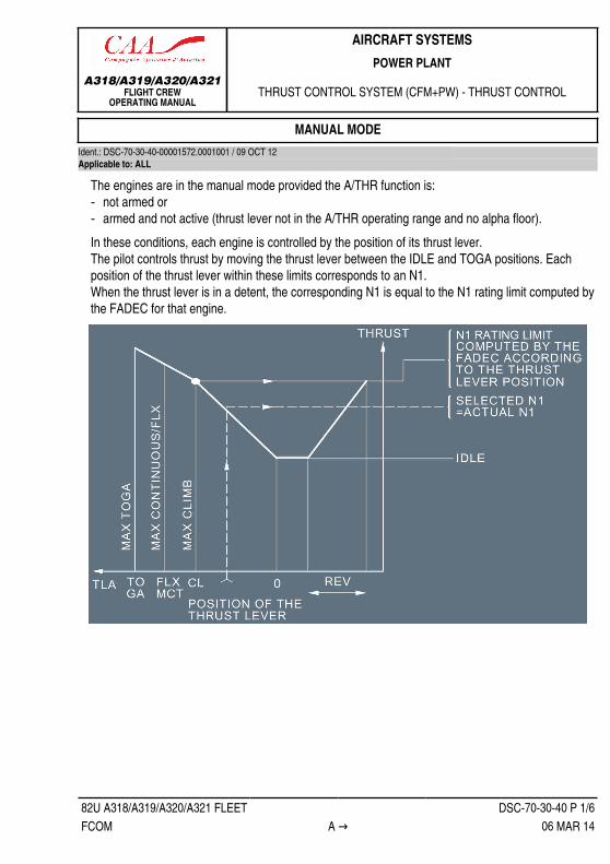
The engines are in the manual mode provided the A/THR function is:‐ not armed or‐ armed and not active (thrust lever not in the A/THR operating range and no alpha floor).In these conditions, each engine is controlled by the position of its thrust lever.The pilot controls thrust by moving the thrust lever between the IDLE and TOGA positions. Eachposition of the thrust lever within these limits corresponds to an N1.When the thrust lever is in a detent, the corresponding N1 is equal to the N1 rating limit computed bythe FADEC for that engine.

A318/A319/A320/A321FLIGHT CREW
OPERATING MANUAL
AIRCRAFT SYSTEMSPOWER PLANT
THRUST CONTROL SYSTEM (CFM+PW) - THRUST CONTROL
82U A318/A319/A320/A321 FLEET DSC-70-30-40 P 2/6FCOM ← A to B → 06 MAR 14
When the thrust lever is in the FLX/MCT detent:‐ On the ground
The engine runs at the flex takeoff thrust rating if the crew has selected a flex takeoff temperatureon the MCDU that is higher than the current Total Air Temperature (TAT).Otherwise the engine produces Maximum Continuous Thrust (MCT).Note: A change in FLEX TEMP during the takeoff has no effect on the thrust.
‐ After takeoffThe pilot can change from FLX to MCT by moving the thrust lever to TOGA or CL, then back toMCT. After that, he cannot use the FLX rating.Note: Setting the thrust lever out of FLX/MCT detent without reaching TOGA or CL detent has
no effect.
The pilot can always get MAX TO thrust by pushing the thrust lever all the way forward.
AUTOMATIC MODEIdent.: DSC-70-30-40-00001573.0001001 / 20 DEC 10Applicable to: MSN 0189
In the autothrust mode (A/THR function active), the FMGC computes the thrust which is limited to thevalue corresponding to the thrust lever position (unless the alpha-floor mode is activated).

A318/A319/A320/A321FLIGHT CREW
OPERATING MANUAL
AIRCRAFT SYSTEMSPOWER PLANT
THRUST CONTROL SYSTEM (CFM+PW) - THRUST CONTROL
82U A318/A319/A320/A321 FLEET DSC-70-30-40 P 3/6FCOM ← B to C → 06 MAR 14
INDICATIONS ON FMAThe FADECs monitor the positions of the thrust levers, and trigger appropriate indications on theFMA.ASYM : appears in amber (3rd line on the FMA) if, with A/THR active and both engines running,
one thrust lever is set out of the CLB detent.CLB : flashes white (2nd line on the FMA) if the thrust levers are not in CL position while the
aircraft is above the altitude of thrust reduction with both engines running.MCT : flashes white (2nd line on the FMA) if the thrust levers are not in MCT position after an
engine failure (with speed above green dot).
AUTOMATIC MODEIdent.: DSC-70-30-40-00001573.0003001 / 20 DEC 10
1 Applicable to: MSN 0112, 0342
In the autothrust mode (A/THR function active), the FMGC computes the thrust which is limited to thevalue corresponding to the thrust lever position (unless the alpha-floor mode is activated).
INDICATIONS ON FMAThe FADECs monitor the positions of the thrust levers, and trigger appropriate indications on theFMA.

A318/A319/A320/A321FLIGHT CREW
OPERATING MANUAL
AIRCRAFT SYSTEMSPOWER PLANT
THRUST CONTROL SYSTEM (CFM+PW) - THRUST CONTROL
82U A318/A319/A320/A321 FLEET DSC-70-30-40 P 4/6FCOM ← C 06 MAR 14
LVRASYM
: appears in amber (3rd line on the FMA) if, with A/THR active and both engines running,one thrust lever is set out of the CLB detent.
LVRCLB
: flashes white (3rd line on the FMA) if the thrust levers are not in CL position while theaircraft is above the altitude of thrust reduction with both engines running.
LVRMCT
: flashes white (3rd line on the FMA) if the thrust levers are not in MCT position after anengine failure (with speed above green dot).

A318/A319/A320/A321FLIGHT CREW
OPERATING MANUAL
AIRCRAFT SYSTEMSPOWER PLANT
THRUST CONTROL SYSTEM (CFM+PW) - THRUST CONTROL
82U A318/A319/A320/A321 FLEET DSC-70-30-40 P 5/6FCOM D → 06 MAR 14
THRUST CONTROLIdent.: DSC-70-30-40-00001574.0001001 / 16 MAR 11

A318/A319/A320/A321FLIGHT CREW
OPERATING MANUAL
AIRCRAFT SYSTEMSPOWER PLANT
THRUST CONTROL SYSTEM (CFM+PW) - THRUST CONTROL
82U A318/A319/A320/A321 FLEET DSC-70-30-40 P 6/6FCOM ← D 06 MAR 14
Applicable to: ALL

A318/A319/A320/A321FLIGHT CREW
OPERATING MANUAL
AIRCRAFT SYSTEMSPOWER PLANT
FUEL SYSTEM (CFM) - GENERAL
82U A318/A319/A320/A321 FLEET DSC-70-40-10 P 1/2FCOM A → 06 MAR 14
GENERALIdent.: DSC-70-40-10-00001585.0003001 / 09 OCT 12
1 Applicable to: ALL
The fuel system supplies fuel to the combustion chamber at the required flow rate, pressure, andtemperature.The fuel flows from the tank, via the fuel pump unit and the fuel/oil heat exchanger, to theHydromechanical Unit (HMU) and to the fuel nozzles.

A318/A319/A320/A321FLIGHT CREW
OPERATING MANUAL
AIRCRAFT SYSTEMSPOWER PLANT
FUEL SYSTEM (CFM) - GENERAL
82U A318/A319/A320/A321 FLEET DSC-70-40-10 P 2/2FCOM ← A 06 MAR 14

A318/A319/A320/A321FLIGHT CREW
OPERATING MANUAL
AIRCRAFT SYSTEMSPOWER PLANT
FUEL SYSTEM (CFM) - FUEL PUMP UNIT
82U A318/A319/A320/A321 FLEET DSC-70-40-20 P 1/2FCOM A 07 OCT 11
FUEL PUMP UNITIdent.: DSC-70-40-20-00001586.0001001 / 09 DEC 09Applicable to: ALL
The HP compressor shaft drives the HP fuel pump assembly. Fuel flows through the LP pump, thenthrough the fuel/oil heat exchanger and the HP pump (gear pump).The fuel then divides into a filtered flow for the servo fuel heater and the servo valves of the HMU,and an unfiltered flow for the metering valve of the HMU.

A318/A319/A320/A321FLIGHT CREW
OPERATING MANUAL
AIRCRAFT SYSTEMSPOWER PLANT
FUEL SYSTEM (CFM) - FUEL PUMP UNIT
Intentionally left blank
82U A318/A319/A320/A321 FLEET DSC-70-40-20 P 2/2FCOM 07 OCT 11

A318/A319/A320/A321FLIGHT CREW
OPERATING MANUAL
AIRCRAFT SYSTEMSPOWER PLANT
FUEL SYSTEM (CFM) - SHUT-OFF VALVES
82U A318/A319/A320/A321 FLEET DSC-70-40-30 P 1/2FCOM A 07 OCT 11
SHUT-OFF VALVESIdent.: DSC-70-40-30-00001587.0001001 / 09 DEC 09Applicable to: ALL
Moving the ENG1 (ENG2) MASTER switch to OFF directly commands the closing of the LP and HPfuel shut off valves for that engine's fuel system.It also closes the fuel return valve and opens the bypass valve.

A318/A319/A320/A321FLIGHT CREW
OPERATING MANUAL
AIRCRAFT SYSTEMSPOWER PLANT
FUEL SYSTEM (CFM) - SHUT-OFF VALVES
Intentionally left blank
82U A318/A319/A320/A321 FLEET DSC-70-40-30 P 2/2FCOM 07 OCT 11

A318/A319/A320/A321FLIGHT CREW
OPERATING MANUAL
AIRCRAFT SYSTEMSPOWER PLANT
FUEL SYSTEM (CFM) - HYDROMECHANICAL UNIT
82U A318/A319/A320/A321 FLEET DSC-70-40-40 P 1/4FCOM A to B → 07 OCT 11
GENERALIdent.: DSC-70-40-40-00001588.0001001 / 09 DEC 09Applicable to: ALL
The FADEC controls the HMU, which :‐ controls fuel flow to the engine combustion chamber‐ controls fuel hydraulic signals to actuators‐ protects against overspeeding.
FUEL FLOWIdent.: DSC-70-40-40-00001589.0002001 / 16 MAR 11Applicable to: ALL
L3 The Fuel Metering Valve (FMV) transforms FADEC orders through a torque motor and servo valveinto fuel flow to the engine fuel nozzles.The FMV resolver generates a feedback signal proportional to the FMV position.The bypass valve maintains a constant pressure drop across the FMV to ensure that the meteredfuel flow is proportional to the FMV position.
L1 The FADEC computes the fuel flow that will maintain the target N1.As the FADEC maintains this N1, it allows N2 to vary while remaining between N2 minimum and N2maximum. The FADEC also controls the engine parameters to :‐ Limit acceleration and deceleration ;‐ Avoid engine stall or flameout ;
A318/A319/A320/A321FLIGHT CREW
OPERATING MANUAL
AIRCRAFT SYSTEMSPOWER PLANT
FUEL SYSTEM (CFM) - HYDROMECHANICAL UNIT
82U A318/A319/A320/A321 FLEET DSC-70-40-40 P 2/4FCOM ← B to D 07 OCT 11
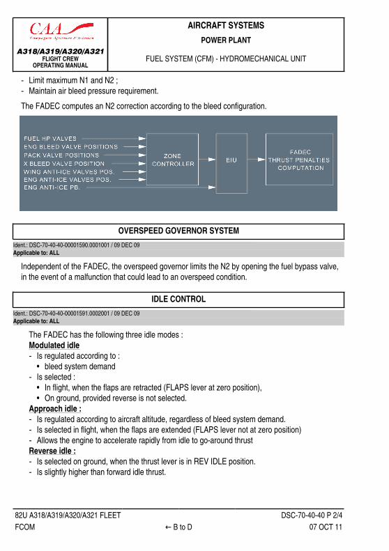
‐ Limit maximum N1 and N2 ;‐ Maintain air bleed pressure requirement.The FADEC computes an N2 correction according to the bleed configuration.
OVERSPEED GOVERNOR SYSTEMIdent.: DSC-70-40-40-00001590.0001001 / 09 DEC 09Applicable to: ALL
Independent of the FADEC, the overspeed governor limits the N2 by opening the fuel bypass valve,in the event of a malfunction that could lead to an overspeed condition.
IDLE CONTROLIdent.: DSC-70-40-40-00001591.0002001 / 09 DEC 09Applicable to: ALL
The FADEC has the following three idle modes :Modulated idle‐ Is regulated according to :
• bleed system demand‐ Is selected :
• In flight, when the flaps are retracted (FLAPS lever at zero position),• On ground, provided reverse is not selected.
Approach idle :‐ Is regulated according to aircraft altitude, regardless of bleed system demand.‐ Is selected in flight, when the flaps are extended (FLAPS lever not at zero position)‐ Allows the engine to accelerate rapidly from idle to go-around thrustReverse idle :‐ Is selected on ground, when the thrust lever is in REV IDLE position.‐ Is slightly higher than forward idle thrust.

A318/A319/A320/A321FLIGHT CREW
OPERATING MANUAL
AIRCRAFT SYSTEMSPOWER PLANT
FUEL SYSTEM (CFM) - HYDROMECHANICAL UNIT
82U A318/A319/A320/A321 FLEET DSC-70-40-40 P 3/4FCOM E → 07 OCT 11
FUEL HYDRAULIC SIGNALSIdent.: DSC-70-40-40-00001592.0001001 / 16 MAR 11Applicable to: ALL
L3 Fuel hydraulic signals go to :‐ Low Pressure Turbine Clearance Control (LPTCC) valves
(Refer to DSC-70-60 General)‐ High Pressure Turbine Clearance Control (HPTCC) valves
(Refer to DSC-70-60 General)‐ Rotor Active Clearance Control (RACC) system
(Refer to DSC-70-60 General)‐ Variable Stator Vanes (VSV)
The VSV system positions the compressor variable vanes.The FADEC maintains optimum compressor efficiency at a steady state and an adequate stallmargin for transient engine operation.VSVs are fully closed during engine start and are fully open at high thrust.

A318/A319/A320/A321FLIGHT CREW
OPERATING MANUAL
AIRCRAFT SYSTEMSPOWER PLANT
FUEL SYSTEM (CFM) - HYDROMECHANICAL UNIT
82U A318/A319/A320/A321 FLEET DSC-70-40-40 P 4/4FCOM ← E 07 OCT 11
‐ Variable Bleed Valves (VBV)The FADEC controls the VBVs, upstream of the HP compressor. Their setting depends oncompressor inlet temperature and on N2. It varies between full open (start, low thrust, and duringfast deceleration) and full closed (high thrust) positions.
‐ Burner Selection Valve (BSV)The FADEC controls the BSV, which allows fuel to go either to 10, or 20 fuel nozzles:• It supplies 10 nozzles permanently.• It supplies the other 10 nozzles when the engine requires a high fuel-air ratio (BSV open).The BSV is closed during engine deceleration and low idle.If the fuel control system fails, an internal safety system ensures that all nozzles are supplied.

A318/A319/A320/A321FLIGHT CREW
OPERATING MANUAL
AIRCRAFT SYSTEMSPOWER PLANT
FUEL SYSTEM (CFM) - IDG COOLING SYSTEM
82U A318/A319/A320/A321 FLEET DSC-70-40-50 P 1/2FCOM A → 15 FEB 13
IDG COOLING SYSTEMIdent.: DSC-70-40-50-00001593.0001001 / 26 JUL 12Applicable to: ALL
Some of the fuel flowing out of the HMU goes to cool the oil systems of the Integrated DriveGenerators (IDGs). It then returns to the fuel pump unit or to the tank.The Fuel Return Valve (FRV), controlled by the FADEC, ensures that this flow is adequate.
L3 At low engine thrust, if the oil going into the IDG is too hot, the cooling fuel is sent back to the tank(300 kg/h).If oil temperature continues to rise, the ECU increases the minimum N2.If oil temperature still keeps rising, the FADEC increases the fuel flow to the tank (from 300 to600 kg/h, depending on fuel return temperature).The fuel return valve is always mixing hot fuel with cold fuel so that the temperature of fuel returningto the tank stays below 100 °C (from 200 to 400 kg/h, depending on fuel return temperature).Fuel recirculation to the tank is inhibited (FRV closed) in the following cases :‐ at engine shutdown‐ during takeoff and climb‐ if :
• wing tank level is below about 300 kg (660 lb).• there is fuel overflow in the surge tank• fuel feed is by gravity only.
‐ when fuel temperature in the wing tank in flight is above 52.5 °CNote: On the ground, high fuel temperature in the wing tank or fuel overflow in the surge tank
does not inhibit the fuel recirculation to the wing tank (FRV remains open).

A318/A319/A320/A321FLIGHT CREW
OPERATING MANUAL
AIRCRAFT SYSTEMSPOWER PLANT
FUEL SYSTEM (CFM) - IDG COOLING SYSTEM
82U A318/A319/A320/A321 FLEET DSC-70-40-50 P 2/2FCOM ← A 15 FEB 13

A318/A319/A320/A321FLIGHT CREW
OPERATING MANUAL
AIRCRAFT SYSTEMSPOWER PLANT
OIL SYSTEM
82U A318/A319/A320/A321 FLEET DSC-70-50 P 1/2FCOM A → 07 OCT 11
GENERALIdent.: DSC-70-50-00001603.0001001 / 16 MAR 11Applicable to: ALL
The oil system lubricates the engine components.It contains :‐ the oil tank‐ the lube and scavenge pump modules‐ the fuel/oil heat exchanger‐ the filters, chip detectors, pressure relief and bypass valves.

A318/A319/A320/A321FLIGHT CREW
OPERATING MANUAL
AIRCRAFT SYSTEMSPOWER PLANT
OIL SYSTEM
82U A318/A319/A320/A321 FLEET DSC-70-50 P 2/2FCOM ← A 07 OCT 11

A318/A319/A320/A321FLIGHT CREW
OPERATING MANUAL
AIRCRAFT SYSTEMSPOWER PLANT
AIRBLEED SYSTEM (CFM)
82U A318/A319/A320/A321 FLEET DSC-70-60 P 1/2FCOM A to B → 30 MAY 12
GENERALIdent.: DSC-70-60-00001604.0002001 / 22 MAY 12Applicable to: ALL
The air bleed system supplies the aircraft with compressed air.It uses the air for:‐ pneumatic system (Refer to DSC-36-10-10 General)‐ cooling the engine compartment and the turbines.
COOLINGIdent.: DSC-70-60-00001605.0002001 / 20 DEC 10Applicable to: ALL
ROTOR ACTIVE CLEARANCE CONTROL (RACC) SYSTEMThe FADEC controls the RACC system through the HMU. The RACC system controls theclearance between the rotor blades of the HP compressor and its stator case.The RACC system uses fifth-stage compressor bleed air that has been modulated according tothe N2 and the flight parameters. The bleed air goes to the N°3 bearing compartment, where it ismixed with fan boost discharge.
A318/A319/A320/A321FLIGHT CREW
OPERATING MANUAL
AIRCRAFT SYSTEMSPOWER PLANT
AIRBLEED SYSTEM (CFM)
82U A318/A319/A320/A321 FLEET DSC-70-60 P 2/2FCOM ← B 30 MAY 12
Clearances are at the maximum when the RACC valve is closed.HP TURBINE CLEARANCE CONTROL (HPTCC) SYSTEM
The FADEC controls the HPTCC system through the HMU. The HPTCC system controls the HPturbine clearance by modulating the HP compressor bleed air flow for cooling the HP turbine case.It optimizes HP turbine performance and reduces exhaust gas temperature.
LP TURBINE CLEARANCE CONTROL (LPTCC) SYSTEMThe FADEC controls the LPTCC system through the HMU. The LPTCC system controls LP turbineclearance by modulating the fan bleed air flow for cooling the LP turbine case.

A318/A319/A320/A321FLIGHT CREW
OPERATING MANUAL
AIRCRAFT SYSTEMSPOWER PLANT
THRUST REVERSER SYSTEM
82U A318/A319/A320/A321 FLEET DSC-70-70 P 1/4FCOM A → 06 MAR 14
GENERALIdent.: DSC-70-70-00001612.0001001 / 09 DEC 09Applicable to: ALL
The aircraft reverses engine thrust by using four pivoting blocker doors on each engine to deflect thefan airstream.
A hydraulic door jack positions each door.‐ The green circuit powers the doors on ENG 1.‐ The yellow circuit powers the doors en ENG 2.The associated FADEC controls the thrust reverser system. Each FADEC channel performs controland monitoring functions. The systems for the two engines are independent of each other.
A318/A319/A320/A321FLIGHT CREW
OPERATING MANUAL
AIRCRAFT SYSTEMSPOWER PLANT
THRUST REVERSER SYSTEM
82U A318/A319/A320/A321 FLEET DSC-70-70 P 2/4FCOM ← A to C 06 MAR 14
The thrust reverser system on each engine has :‐ 4 actuators,‐ 4 latches,‐ Door position switches,‐ A Hydraulic Control Unit (HCU) that :
• Pressurizes the thrust reverser hydraulic system,• Regulates the speed of the blocker doors, and• Supplies actuators with hydraulic power.
Each pivoting door moves independently (the doors are not synchronized).The total actuation time is less than two seconds.
ACTUATION LOGICIdent.: DSC-70-70-00001613.0001001 / 09 DEC 09Applicable to: ALL
Deployment requires :‐ One FADEC channel, operating with its associated throttle reverse signal ;‐ Right and left main gear compressed signal from the corresponding LGCIUs ;‐ A Thrust Lever Angle (TLA) reverse signals from at least one Spoiler Elevator Computer (SEC).Before deployment is completed, the FADEC sets reverse idle thrust on the engine that is having itsthrust reversed.
PROTECTIONIdent.: DSC-70-70-00001614.0004001 / 09 DEC 09
1 Applicable to: ALL
‐ AUTO RESTOW FUNCTIONThe FADEC will automatically command the reverse to stow, if at least one door is unstowed andreverse thrust is not selected while the engine is running.Auto restow is totally inhibited in flight, and on ground, with N1 greater than 70 %.
‐ IDLE PROTECTIONThe FADEC will automatically select idle thrust if reverse thrust is not selected and :• The four doors are detected unstowed, or• At least one door is detected unstowed, and hydraulic pressure is detected in the HCU
(downstream of the pressurizing valve), or• The door position is indefinite, and hydraulic pressure is detected in the HCU (downstream of
the pressurizing valve).
A318/A319/A320/A321FLIGHT CREW
OPERATING MANUAL
AIRCRAFT SYSTEMSPOWER PLANT
THRUST REVERSER SYSTEM
82U A318/A319/A320/A321 FLEET DSC-70-70 P 3/4FCOM D 06 MAR 14
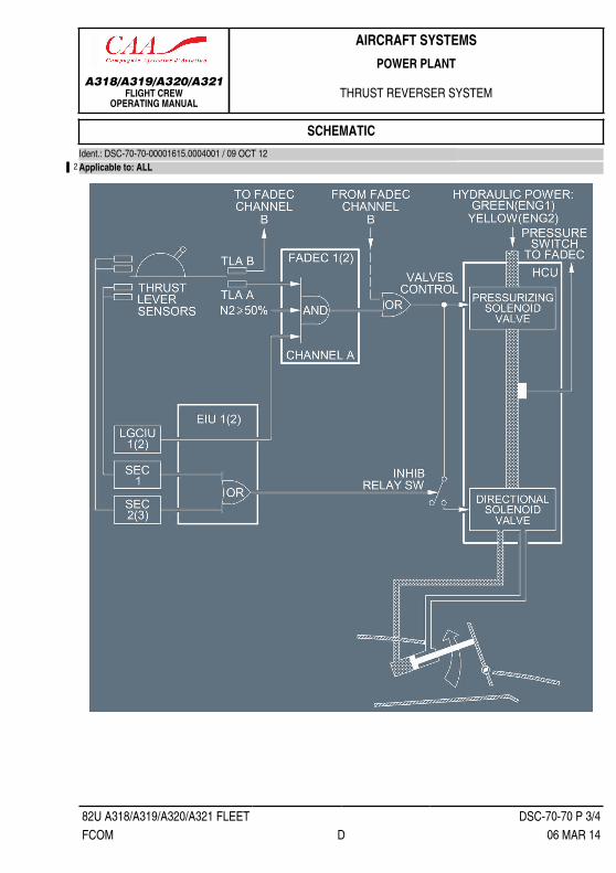
SCHEMATICIdent.: DSC-70-70-00001615.0004001 / 09 OCT 12
2 Applicable to: ALL

A318/A319/A320/A321FLIGHT CREW
OPERATING MANUAL
AIRCRAFT SYSTEMSPOWER PLANT
THRUST REVERSER SYSTEM
Intentionally left blank
82U A318/A319/A320/A321 FLEET DSC-70-70 P 4/4FCOM 06 MAR 14
A318/A319/A320/A321FLIGHT CREW
OPERATING MANUAL
AIRCRAFT SYSTEMSPOWER PLANT
IGNITION AND STARTING - GENERAL
82U A318/A319/A320/A321 FLEET DSC-70-80-10 P 1/2FCOM A 07 OCT 11
GENERALIdent.: DSC-70-80-10-00001616.0001001 / 15 FEB 11Applicable to: ALL
The FADEC controls the ignition and starting system according to :‐ the position of the engine start selector‐ the position of the ENG MASTER switch‐ the position of the ENG MAN START pushbutton switch‐ the position of the ENG 1(2) ANTI ICE pushbutton switch‐ the aircraft status (flight or ground).The FADEC receives its inputs from the Engine Interface Unit (EIU).

A318/A319/A320/A321FLIGHT CREW
OPERATING MANUAL
AIRCRAFT SYSTEMSPOWER PLANT
IGNITION AND STARTING - GENERAL
Intentionally left blank
82U A318/A319/A320/A321 FLEET DSC-70-80-10 P 2/2FCOM 07 OCT 11

A318/A319/A320/A321FLIGHT CREW
OPERATING MANUAL
AIRCRAFT SYSTEMSPOWER PLANT
IGNITION AND STARTING - ARCHITECTURE
82U A318/A319/A320/A321 FLEET DSC-70-80-20 P 1/2FCOM A 07 OCT 11
ARCHITECTUREIdent.: DSC-70-80-20-00001617.0002001 / 17 MAR 11Applicable to: ALL

A318/A319/A320/A321FLIGHT CREW
OPERATING MANUAL
AIRCRAFT SYSTEMSPOWER PLANT
IGNITION AND STARTING - ARCHITECTURE
Intentionally left blank
82U A318/A319/A320/A321 FLEET DSC-70-80-20 P 2/2FCOM 07 OCT 11

A318/A319/A320/A321FLIGHT CREW
OPERATING MANUAL
AIRCRAFT SYSTEMSPOWER PLANT
IGNITION AND STARTING - IGNITION SYSTEM
82U A318/A319/A320/A321 FLEET DSC-70-80-30 P 1/4FCOM A 07 OCT 11
GENERALIdent.: DSC-70-80-30-00001618.0001001 / 09 DEC 09Applicable to: ALL
The ignition system is for engine starting on the ground and restarting in flight. It consists of twoidentical independent circuits for each engine, normally controlled by the FADEC channel A andchannel B. Each FADEC channel can control both igniters.
Note: Supply for igniter A switches to the STAT INV BUS BAR as soon as the static inverter isoperative.

A318/A319/A320/A321FLIGHT CREW
OPERATING MANUAL
AIRCRAFT SYSTEMSPOWER PLANT
IGNITION AND STARTING - IGNITION SYSTEM
82U A318/A319/A320/A321 FLEET DSC-70-80-30 P 2/4FCOM B to C → 07 OCT 11
IGNITION FOR STARTINGIdent.: DSC-70-80-30-00001619.0004001 / 15 FEB 11Applicable to: ALL
ON THE GROUND‐ Automatic start:
• Only one igniter is supplied.• The FADEC automatically alternates the use of igniters for the engine start of the successive
flights following the sequence below:▪ channel A, igniter A▪ channel A, igniter B▪ channel B, igniter A▪ channel B, igniter B
• The ignition comes on automatically when N2 reaches 16 % and cuts off automatically whenN2 reaches 50 %.
• If the automatic start fails, the FADEC energizes both igniters at the same time during thesecond attempt at an engine start.
‐ Manual start:• Both igniters start firing when the ENG MASTER sw is set to ON.• Both igniters are cut off when N2 reaches approximately 50 %.
IN FLIGHTBoth igniters are supplied when the ENG MASTER sw is set to ON.
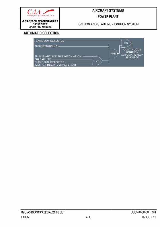
CONTINUOUS IGNITIONIdent.: DSC-70-80-30-00001620.0001001 / 15 FEB 11Applicable to: ALL
Continuous ignition may be selected either manually or automatically to maintain engine combustion.MANUAL SELECTION
In flight, continuous ignition is on when the ENG START selector is on IGN/START, if thecorresponding engine is running.Only one igniter is selected. If failed, both igniters are automatically selected.On the ground after the engine is started, because ignition cuts off automatically, the flight crewmust switch the ENG MODE selector to NORM then back to IGN/START to turn on continuousignition.
A318/A319/A320/A321FLIGHT CREW
OPERATING MANUAL
AIRCRAFT SYSTEMSPOWER PLANT
IGNITION AND STARTING - IGNITION SYSTEM
82U A318/A319/A320/A321 FLEET DSC-70-80-30 P 3/4FCOM ← C 07 OCT 11
AUTOMATIC SELECTION

A318/A319/A320/A321FLIGHT CREW
OPERATING MANUAL
AIRCRAFT SYSTEMSPOWER PLANT
IGNITION AND STARTING - IGNITION SYSTEM
Intentionally left blank
82U A318/A319/A320/A321 FLEET DSC-70-80-30 P 4/4FCOM 07 OCT 11

A318/A319/A320/A321FLIGHT CREW
OPERATING MANUAL
AIRCRAFT SYSTEMSPOWER PLANT
IGNITION AND STARTING - ENGINE STARTING SYSTEM
82U A318/A319/A320/A321 FLEET DSC-70-80-40 P 1/8FCOM A to B 06 MAR 14
GENERALIdent.: DSC-70-80-40-00001621.0001001 / 25 FEB 14Applicable to: ALL
1 The engine starting system consists of an air turbine starter and a start valve.The start valve admits air supplied by the pneumatic system to operate the starter.The FADEC controls the start valve electrically and bleed pressure is required for opening the startvalve. If electrical control fails when the aircraft is on the ground, a handle allows the start valve to beoperated manually.
AUTOMATIC STARTINGIdent.: DSC-70-80-40-00001622.0004001 / 15 FEB 11Applicable to: ALL
This sequence is under the full authority of the FADEC, which controls:‐ the start valve‐ the igniters‐ the fuel HP valvesThe FADEC :‐ detects a hot start, a hung start, a stall, or no light up‐ announces FAULT and identifies the fault in an ECAM message‐ runs an abort sequence if a start aborts on the ground due to hot start, hung start, stall or no light
up.• closes the HP valve• closes the start valve• turns off ignition• cranks the engine crank after the start abort in order to clear out fuel vapors• controls any additional start attemps.
For an inflight start, the FADEC decides whether the engine is windmilling fast enough or needsassistance from the starter in view of current engine parameters and flight environment parameters.Flight crew may interrupt this start sequence by moving the MASTER switch to OFF.
A318/A319/A320/A321FLIGHT CREW
OPERATING MANUAL
AIRCRAFT SYSTEMSPOWER PLANT
IGNITION AND STARTING - ENGINE STARTING SYSTEM
82U A318/A319/A320/A321 FLEET DSC-70-80-40 P 2/8FCOM C → 06 MAR 14
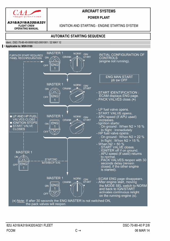
AUTOMATIC STARTING SEQUENCEIdent.: DSC-70-80-40-00001623.0001001 / 22 MAY 12
2 Applicable to: MSN 0189

A318/A319/A320/A321FLIGHT CREW
OPERATING MANUAL
AIRCRAFT SYSTEMSPOWER PLANT
IGNITION AND STARTING - ENGINE STARTING SYSTEM
82U A318/A319/A320/A321 FLEET DSC-70-80-40 P 3/8FCOM ← C 06 MAR 14
AUTOMATIC STARTING SEQUENCEIdent.: DSC-70-80-40-00001623.0005001 / 22 MAY 12Applicable to: MSN 0112, 0342

A318/A319/A320/A321FLIGHT CREW
OPERATING MANUAL
AIRCRAFT SYSTEMSPOWER PLANT
IGNITION AND STARTING - ENGINE STARTING SYSTEM
82U A318/A319/A320/A321 FLEET DSC-70-80-40 P 4/8FCOM D to E 06 MAR 14
MANUAL STARTINGIdent.: DSC-70-80-40-00001624.0001001 / 09 DEC 09Applicable to: ALL
The FADEC has limited authority over manual starting controlling :‐ the opening of the start valve when the ENG MODE selector is set to IGN/START and the MAN
START pushbutton switch is pressed.‐ the position of the HP fuel valve and the operation of both igniters, when the master switch is
turned ON‐ the closing of the start valve at approximately 50 % N2, and, on the ground, the cutting off of
ignition.The FADEC makes a passive survey of the engine during the starting sequence : the flight crew ismade aware of an abnormal start by a proper ECAM warning and has to interrupt the start sequence.The FADEC has not the authority to abort the manual start :‐ in flight‐ on ground, except if the start EGT limit is exceeded before reaching 50 % N2. In this case only,
the FADEC aborts the start.Flight crew may interrupt the starting sequence :‐ before the MASTER switch is set to ON, by switching the MAN START pushbutton switch to OFF‐ after the MASTER switch set to ON, by switching the MAN START pushbutton and the MASTER
switch to OFF (flight crew must perform a dry cranking cycle).In flight, the FADEC always commands a starter-assisted air start.
ENGINE VENTILATION (DRY CRANKING)Ident.: DSC-70-80-40-00001625.0001001 / 15 FEB 11Applicable to: ALL
A dry cranking cycle ventilates the engine to remove fuel vapors after an unsuccessful start attempton the ground.The flight crew can manually select cranking by setting the ENG MODE selector to CRANK and theMAN START pushbutton switch to ON (MASTER switch OFF). Flight crew can stop the cranking bysetting the MAN START pushbutton switch to OFF.
A318/A319/A320/A321FLIGHT CREW
OPERATING MANUAL
AIRCRAFT SYSTEMSPOWER PLANT
IGNITION AND STARTING - ENGINE STARTING SYSTEM
82U A318/A319/A320/A321 FLEET DSC-70-80-40 P 5/8FCOM F → 06 MAR 14
MANUAL STARTING SEQUENCEIdent.: DSC-70-80-40-00001626.0001001 / 15 FEB 11

A318/A319/A320/A321FLIGHT CREW
OPERATING MANUAL
AIRCRAFT SYSTEMSPOWER PLANT
IGNITION AND STARTING - ENGINE STARTING SYSTEM
82U A318/A319/A320/A321 FLEET DSC-70-80-40 P 6/8FCOM ← F → 06 MAR 14
3 Applicable to: MSN 0189

A318/A319/A320/A321FLIGHT CREW
OPERATING MANUAL
AIRCRAFT SYSTEMSPOWER PLANT
IGNITION AND STARTING - ENGINE STARTING SYSTEM
82U A318/A319/A320/A321 FLEET DSC-70-80-40 P 7/8FCOM ← F → 06 MAR 14
MANUAL STARTING SEQUENCEIdent.: DSC-70-80-40-00001626.0005001 / 15 FEB 11Applicable to: MSN 0112, 0342

A318/A319/A320/A321FLIGHT CREW
OPERATING MANUAL
AIRCRAFT SYSTEMSPOWER PLANT
IGNITION AND STARTING - ENGINE STARTING SYSTEM
82U A318/A319/A320/A321 FLEET DSC-70-80-40 P 8/8FCOM ← F 06 MAR 14
(1) Refer to DSC-21-10-20 Pack Flow Control Valve

A318/A319/A320/A321FLIGHT CREW
OPERATING MANUAL
AIRCRAFT SYSTEMSPOWER PLANT
CONTROLS AND INDICATORS (CFM)
82U A318/A319/A320/A321 FLEET DSC-70-90 P 1/26FCOM A → 06 MAR 14
PEDESTALIdent.: DSC-70-90-00001627.0001001 / 22 MAY 12Applicable to: ALL
(1) Thrust levers(Refer to DSC-70-30-20 Thrust Levers).
(2) Reverser latching leversThese permit the pilot to override the stop at the forward idle position to select reverse thrust.This stop resets when the pilot moves the lever back into the forward thrust area.
(3) Autothrust instinctive disconnect pb(Refer to DSC-22_30-90 A/THR Disconnection - General).

A318/A319/A320/A321FLIGHT CREW
OPERATING MANUAL
AIRCRAFT SYSTEMSPOWER PLANT
CONTROLS AND INDICATORS (CFM)
82U A318/A319/A320/A321 FLEET DSC-70-90 P 2/26FCOM ← A → 06 MAR 14
(1) ENG MODE selectorCRANK : The start valve opens, if the MAN START pb-sw is ON. Ignition does not fire.NORM : This turns on continuous ignition (A and B) when the engine is running, and:
‐ The ENG ANTI-ICE pb-sw is ON, or‐ A flame-out is detected, or‐ An EIU fails.
IGNSTART
: If the MASTER sw is ON and N2 ≥ idle, this position selects continuous ignition(A and B):‐ During an automatic start:
• On ground, when N2 passes 16 %, ignition switches to A or B.However, if there is an ignition delay during the start sequence, ignition iscontinuous (A and B)
• In flight, continuous ignition (A and B) begins when the start sequencebegins.
‐ During a manual start, ignition begins when the MASTER sw is turned ON.The pack valve closes automatically during the start sequence. (Refer to DSC-21-10-10General).Note: On ground, ignition shuts off automatically at the end of the start sequence (N2 >
50 %).

A318/A319/A320/A321FLIGHT CREW
OPERATING MANUAL
AIRCRAFT SYSTEMSPOWER PLANT
CONTROLS AND INDICATORS (CFM)
82U A318/A319/A320/A321 FLEET DSC-70-90 P 3/26FCOM ← A to B → 06 MAR 14
(2) ENG 1 (2) MASTER swON : LP fuel valve opens (if the ENG FIRE pb is in):
‐ During an automatic start, the HP fuel valve opens if:• The ENG MODE selector is at IGN/START.• N2 is above the following threshold:
▪ 22 % on the ground▪ 15 % in flight
‐ During a manual start, the HP FUEL valve opens if:• The ENG MODE selector is at IGN/START.• The MAN START pb-sw is ON.
OFF: Close signals go directly to the HP fuel valve and the LP fuel valve. These signalscause both channels of the FADEC to be reset.
(3) ENG 1 (2) FAULT lightFAULTlight
: This amber light comes on, and a caution appears on ECAM, if there is:‐ an automatic start abort‐ a disagreement between the HP fuel valve position and its commanded
position.
OVERHEAD PANELIdent.: DSC-70-90-00001628.0001001 / 07 MAY 13Applicable to: ALL

A318/A319/A320/A321FLIGHT CREW
OPERATING MANUAL
AIRCRAFT SYSTEMSPOWER PLANT
CONTROLS AND INDICATORS (CFM)
82U A318/A319/A320/A321 FLEET DSC-70-90 P 4/26FCOM ← B to D → 06 MAR 14
(1) ENG MAN START pb sw (guarded)ON : The start valve opens if the ENG MODE selector is set to CRANK or IGN/START and
N2 < 20 %.Both pack valves close during the start sequence.Note: The start valve closes automatically when N2 ≥ 50 %.The blue ON light comes on.
Off : When the ENG MAN START pushbutton switch is set to OFF during a manual enginestart, the start valve closes if the MASTER switch is OFF.
MAINTENANCE PANELIdent.: DSC-70-90-00001629.0001001 / 07 MAY 13Applicable to: ALL
(1) FADEC GND PWR pb sw (guarded)ON : FADEC has electrical power on the ground if the ENG FIRE pushbutton is not
released.
ECAMIdent.: DSC-70-90-A-00001630.0001001 / 17 MAR 11Applicable to: ALL
GENERALThe ECAM’s upper E/WD permanently displays the engines’ primary parameters. The ECAM’slower SD displays the secondary parameters, either when they are automatically selected by thesystem, or manually selected by the flight crew.

A318/A319/A320/A321FLIGHT CREW
OPERATING MANUAL
AIRCRAFT SYSTEMSPOWER PLANT
CONTROLS AND INDICATORS (CFM)
82U A318/A319/A320/A321 FLEET DSC-70-90 P 5/26FCOM ← D → 06 MAR 14
Ident.: DSC-70-90-A-00001631.0001001 / 09 OCT 12Applicable to: MSN 0112-0189
PRIMARY PARAMETER
(1) LP rotor speed (N1)
(A) Actual N1The N1 needle and N1 digital indication are normally in green. They pulse in:‐ Amber, when the actual N1 is above the N1 MAX (See (E)).‐ Red, when the actual N1 is above the N1 RED line (102 %).
When the N1 is degraded (in case both N1 sensors fail), the last digit of the digitaldisplay is dashed in amber.

A318/A319/A320/A321FLIGHT CREW
OPERATING MANUAL
AIRCRAFT SYSTEMSPOWER PLANT
CONTROLS AND INDICATORS (CFM)
82U A318/A319/A320/A321 FLEET DSC-70-90 P 6/26FCOM ← D → 06 MAR 14
(B) N1 CommandThis N1 corresponds to the demand of the autothrust system (A/THR), as limited by theposition of the thrust lever. It is displayed only if A/THR is on.
(C) Transient N1This blue arc shows the difference between the actual N1 and the N1 commanded bythe A/THR. It is displayed only if the A/THR is on.
(D) N1 TLAThis small white circle shows the N1 corresponding to the thrust lever position.
(E) MAX N1the MAX N1 amber index displays the N1 that the engine produces when the thrustlevers are in full forward position or when MAX REVERSE is set.
(F) MAX permissible N1This red arc, showing the prohibited or “redline” area of operation, begins at 102 %.
(G) N1 exceedanceif N1 exceeds 102 % during a flight, this red mark appears and remains at the highestN1 attained. It disappears after a new start on the ground or after maintenance actionthrough the MCDU.
(H) REVappears in amber when any one blocker door is unstowed or unlocked.It changes to green when all four blocker doors are fully deployed.(If a door unlocks in flight the indication first flashes for 9 s, then remains steady).
(2) Thrust limit modeTOGA, FLX, CL, MCT, or MREV limit mode, selected by the position of whichever thrustlever is farther forward, is displayed in blue.
(3) N1 rating limitIt is computed by the FADEC for the present thrust lever angle, and is displayed in green.Note: When the aircraft is on ground with the engines running, the N1 rating limit
displayed here corresponds to the TOGA thrust limit, regardless of the thrust leverposition.When the aircraft is on ground with the engines running and FLEX mode isselected, this number is the FLEX N1, regardless of the thrust lever positionbetween idle and FLX/MCT.
(4) FLEX temperatureIf FLX mode is selected, the flexible takeoff temperature selected through the MCDUs isdisplayed in blue.
A318/A319/A320/A321FLIGHT CREW
OPERATING MANUAL
AIRCRAFT SYSTEMSPOWER PLANT
CONTROLS AND INDICATORS (CFM)
82U A318/A319/A320/A321 FLEET DSC-70-90 P 7/26FCOM ← D → 06 MAR 14
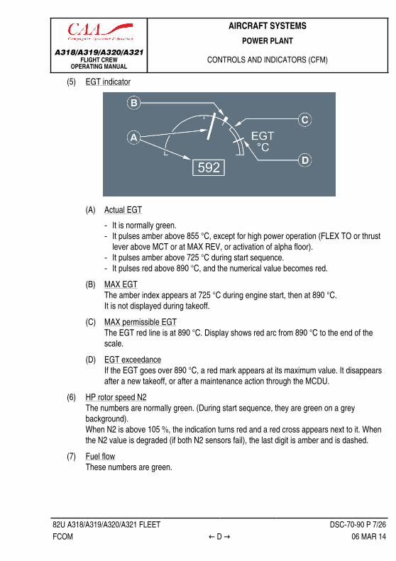
(5) EGT indicator
(A) Actual EGT‐ It is normally green.‐ It pulses amber above 855 °C, except for high power operation (FLEX TO or thrust
lever above MCT or at MAX REV, or activation of alpha floor).‐ It pulses amber above 725 °C during start sequence.‐ It pulses red above 890 °C, and the numerical value becomes red.
(B) MAX EGTThe amber index appears at 725 °C during engine start, then at 890 °C.It is not displayed during takeoff.
(C) MAX permissible EGTThe EGT red line is at 890 °C. Display shows red arc from 890 °C to the end of thescale.
(D) EGT exceedanceIf the EGT goes over 890 °C, a red mark appears at its maximum value. It disappearsafter a new takeoff, or after a maintenance action through the MCDU.
(6) HP rotor speed N2The numbers are normally green. (During start sequence, they are green on a greybackground).When N2 is above 105 %, the indication turns red and a red cross appears next to it. Whenthe N2 value is degraded (if both N2 sensors fail), the last digit is amber and is dashed.
(7) Fuel flowThese numbers are green.

A318/A319/A320/A321FLIGHT CREW
OPERATING MANUAL
AIRCRAFT SYSTEMSPOWER PLANT
CONTROLS AND INDICATORS (CFM)
82U A318/A319/A320/A321 FLEET DSC-70-90 P 8/26FCOM ← D → 06 MAR 14
Note: If the system detects a discrepancy between the N1, N2, EGT and fuel flow valueson the FADEC-DMC bus and the corresponding displayed values, an amberCHECK appears underneath the affected parameter.
Ident.: DSC-70-90-A-00001631.0004001 / 07 MAY 131 Applicable to: MSN 0342
PRIMARY PARAMETER
(1) LP rotor speed (N1)

A318/A319/A320/A321FLIGHT CREW
OPERATING MANUAL
AIRCRAFT SYSTEMSPOWER PLANT
CONTROLS AND INDICATORS (CFM)
82U A318/A319/A320/A321 FLEET DSC-70-90 P 9/26FCOM ← D → 06 MAR 14
(A) Actual N1The N1 needle and N1 digital indication are normally in green. They pulse in:‐ Amber, when the actual N1 is above the N1 MAX (See (E)).‐ Red, when the actual N1 is above the N1 RED line (102 %).
When the N1 is degraded (in case both N1 sensors fail), the last digit of the digitaldisplay is dashed in amber.
(B) N1 CommandThis N1 corresponds to the demand of the autothrust system (A/THR), as limited by theposition of the thrust lever. It is displayed only if A/THR is on.
(C) Transient N1This blue arc shows the difference between the actual N1 and the N1 commanded bythe A/THR. It is displayed only if the A/THR is on.
(D) N1 TLAThis small white circle shows the N1 corresponding to the thrust lever position.
(E) MAX N1the MAX N1 amber index displays the N1 that the engine produces when the thrustlevers are in full forward position or when MAX REVERSE is set.
(F) MAX permissible N1This red arc, showing the prohibited or “redline” area of operation, begins at 102 %.
(G) N1 exceedanceif N1 exceeds 102 % during a flight, this red mark appears and remains at the highestN1 attained. It disappears after a new start on the ground or after maintenance actionthrough the MCDU.
(H) REVappears in amber when any one blocker door is unstowed or unlocked.It changes to green when all four blocker doors are fully deployed.(If a door unlocks in flight the indication first flashes for 9 s, then remains steady).
(2) Thrust limit modeTOGA, FLX, CL, MCT, or MREV limit mode, selected by the position of whichever thrustlever is farther forward, is displayed in blue.
(3) N1 rating limitIt is computed by the FADEC for the present thrust lever angle, and is displayed in green.

A318/A319/A320/A321FLIGHT CREW
OPERATING MANUAL
AIRCRAFT SYSTEMSPOWER PLANT
CONTROLS AND INDICATORS (CFM)
82U A318/A319/A320/A321 FLEET DSC-70-90 P 10/26FCOM ← D → 06 MAR 14
Note: When the aircraft is on ground with the engines running, the N1 rating limitdisplayed here corresponds to the TOGA thrust limit, regardless of the thrust leverposition.When the aircraft is on ground with the engines running and FLEX mode isselected, this number is the FLEX N1, regardless of the thrust lever positionbetween idle and FLX/MCT.
(4) FLEX temperatureIf FLX mode is selected, the flexible takeoff temperature selected through the MCDUs isdisplayed in blue.
(5) EGT indicator
(A) Actual EGT‐ It is normally green.‐ It pulses amber above 855 °C, except for high power operation (FLEX TO or thrust
lever above MCT or at MAX REV, or activation of alpha floor).‐ It pulses amber above 725 °C during start sequence.‐ It pulses red above 890 °C, and the numerical value becomes red.
(B) MAX EGTThe amber index appears at 725 °C during engine start, then at 890 °C.It is not displayed during takeoff.
(C) MAX permissible EGTThe EGT red line is at 890 °C. Display shows red arc from 890 °C to the end of thescale.
(D) EGT exceedanceIf the EGT goes over 890 °C, a red mark appears at its maximum value. It disappearsafter a new takeoff, or after a maintenance action through the MCDU.

A318/A319/A320/A321FLIGHT CREW
OPERATING MANUAL
AIRCRAFT SYSTEMSPOWER PLANT
CONTROLS AND INDICATORS (CFM)
82U A318/A319/A320/A321 FLEET DSC-70-90 P 11/26FCOM ← D → 06 MAR 14
(6) HP rotor speed N2The numbers are normally green. (During start sequence, they are green on a greybackground).When N2 is above 105 %, the indication turns red and a red cross appears next to it. Whenthe N2 value is degraded (if both N2 sensors fail), the last digit is amber and is dashed.
(7) Fuel flowThese numbers are green.Note: If the system detects a discrepancy between the N1, N2, EGT and fuel flow values
on the FADEC-DMC bus and the corresponding displayed values, an amberCHECK appears underneath the affected parameter.
(8) IDLE indicationThis legend appears in green when both engines are at idle. It flashes for 10 s, then remainssteady.
Ident.: DSC-70-90-A-00001632.0002001 / 08 AUG 13Applicable to: ALL
SECONDARY PARAMETERSNORMAL CONFIGURATION
(1) Fuel usedThe green number is the fuel used as computed by the DMC.
A318/A319/A320/A321FLIGHT CREW
OPERATING MANUAL
AIRCRAFT SYSTEMSPOWER PLANT
CONTROLS AND INDICATORS (CFM)
82U A318/A319/A320/A321 FLEET DSC-70-90 P 12/26FCOM ← D → 06 MAR 14
The green number resets, when the engine starts (MASTER switch ON) on the ground.The green number is frozen at the last value (until the next engine start), when the engineshuts down. (The CRUISE SD page also displays the last value).The fuel used indication is dashed when the indication is inaccurate due to the loss of fuelflow data for more than 1 min.
(2) Oil quantityThe oil quantity indicators (needle and values) are green.The indication pulses, when oil quantity decreases below three quarts or increases abovefive quarts.
(3) Oil pressureThe oil pressure indicators (needle and values) are green.If the oil pressure:‐ Exceeds 90 PSI, the indicators begin to pulse
The indicators stop pulsing, when the oil pressure goes below 85 PSI.‐ Goes below 16 PSI, the indicators begin to pulse
The indicators stop pulsing, when the oil pressure returns above 20 PSI.‐ Goes below 13 PSI, the indicators become red, and the ECAM displays the ENG 1(2)
OIL LO PR alert.
(4) Oil temperatureThe oil temperature values are green.If the oil temperature:‐ Exceeds 140 °C, the value begins to pulse
The value stops pulsing, when the oil temperature goes below 135 °C.‐ Exceeds 140 °C for more than 15 min, the value becomes amber, and the ECAM
displays the ENG 1(2) OIL HI TEMP alert‐ Rapidly exceeds 155 °C, the value becomes amber, and the ECAM displays the ENG
1(2) OIL HI TEMP alert.
(5) VIBThe legend is green.VIB N1 pulses above 6.VIB N2 pulses above 4.3.(These numbers also appear on the CRUISE SD page).
(6) Oil filter clogCLOG appears in amber, if there is an excessive pressure loss across the main oilscavenge filter.

A318/A319/A320/A321FLIGHT CREW
OPERATING MANUAL
AIRCRAFT SYSTEMSPOWER PLANT
CONTROLS AND INDICATORS (CFM)
82U A318/A319/A320/A321 FLEET DSC-70-90 P 13/26FCOM ← D 06 MAR 14
(7) Fuel filter clogCLOG appears in amber, if there is an excessive pressure loss across the fuel filter.
(8) IgnitionIGN appears in white during the start sequence.The letters A, B, or AB appear in green, when the respective igniters are firing.
(9) Start valve positionIn line – Green : The valve is fully open.Crossline – Green : The valve is fully closed.
(10) Engine bleed pressureThe green numbers indicate the bleed pressure upstream of the precooler.They become amber, when the pressure drops below 21 PSI with N2 ≥ 10 %, or if there isan overpressure.
ONE NAC TEMPERATURE ABOVE 240 °C
(11) Nacelle temperatureThe screen displays both nacelle temperatures if at least one of them is above 240 °C.A nacelle temperature above 240 °C pulses green.During the start sequence, an ignition indication replaces these temperatures.

A318/A319/A320/A321FLIGHT CREW
OPERATING MANUAL
AIRCRAFT SYSTEMSPOWER PLANT
CONTROLS AND INDICATORS (CFM)
82U A318/A319/A320/A321 FLEET DSC-70-90 P 14/26FCOM E → 06 MAR 14
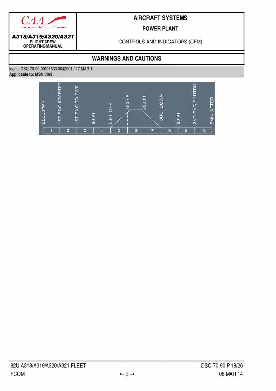
WARNINGS AND CAUTIONSIdent.: DSC-70-90-00001633.0016001 / 17 MAR 11Applicable to: MSN 0342

A318/A319/A320/A321FLIGHT CREW
OPERATING MANUAL
AIRCRAFT SYSTEMSPOWER PLANT
CONTROLS AND INDICATORS (CFM)
82U A318/A319/A320/A321 FLEET DSC-70-90 P 15/26FCOM ← E → 06 MAR 14
E/WD: FAILURE TITLEconditions
AURALWARNING
MASTERLIGHT
SD PAGECALLED
LOCALWARNING
FLTPHASEINHIB
ENG DUAL FAILURE
Associatedwith GENFAULT ltsand PACKFAULT lt
NIL
ENG 1(2) OIL LO PROil low pressure triggered at 13 PSI by the oilpressure switch.
CRC MASTERWARN
1, 10
ENG STALLNIL
ENG 1(2) HP FUEL VALVEHP fuel valve failed closed.
3, 4,5, 7, 8
ENG 1(2) START FAULTStart fault due to:‐ No light up, or‐ ENG stall or over TEMP (above 725 °C), or‐ Starter time exceeded‐ Low start air PRESS
3, 4, 5,6, 7, 8
ENG 1(2) START VALVE FAULTPosition disagree.
AssociatedFAULT lt onENG panelon pedestal(exception
case ofstarter timeexceeded)
3, 4,5, 7, 8
ENG 1(2) THR LEVER DISAGREEDisagree between both resolvers of a thrust lever. 4, 5, 8
ENG 1(2) OIL HI TEMPOil TEMP between 140 and 155 °C for more than15 min, or oil TEMP above 155 °C.ENG 1(2) FADEC FAULTBoth channels failed.
4, 5, 7, 8
ENG 1(2) LOW N1No N1 rotation during start.
SINGLECHIME
MASTERCAUT
ENG
4, 5, 6, 7,8, 9, 10
ENG THRUST LOCKEDThrust levers are not moved within 5 s, followingan unvoluntary disconnection of the A/THR (ordisconnection through the FCU pb).
SINGLECHIME
every 5 s
MASTERCAUT
every 5 s
1, 2, 3, 4,8, 9, 10
ENG FLEX TEMP NOT SETFlex TEMP has not been entered on the MCDU.
SINGLECHIME
MASTERCAUT
NIL
NIL
1, 4, 5, 6,7, 8, 10
Continued on the following page

A318/A319/A320/A321FLIGHT CREW
OPERATING MANUAL
AIRCRAFT SYSTEMSPOWER PLANT
CONTROLS AND INDICATORS (CFM)
82U A318/A319/A320/A321 FLEET DSC-70-90 P 16/26FCOM ← E → 06 MAR 14
Continued from the previous page
E/WD: FAILURE TITLEconditions
AURALWARNING
MASTERLIGHT
SD PAGECALLED
LOCALWARNING
FLTPHASEINHIB
ENG 1(2) FADEC HI TEMP 3, 4,5, 7, 8
ENG TYPE DISAGREERating discrepancy between the two engines. 3 to 10
ENG 1(2) THR LEVER FAULTBoth resolvers on one thrust lever have failed. 5
ENG 1(2) FAILENG core speed below idle, with master sw ONand fire pb not pushed.ENG 1(2) SHUT DOWNENG master at off in phases 3 to 8, or ENG FIREpb pushed in phases 1, 2, 9 and 10.
1, 10
ENG 1(2) REVERSE UNLOCKEDOne or more reverser doors not locked in stowedposition in flight, or on ground with no deploy order.
4, 5, 8((1))
ENG 1(2) REV PRESSURIZEDReverser system is pressurized, while rev doorsare stowed and locked with no deploy order.
4, 5, 8
ENG 1(2) COMPRESSOR VANEVariable bleed valve SYS or variable stator vaneSYS fault.
4, 5, 7, 8
ENG 1(2) N1 or N2 or EGT OVER LIMITN1 above 102.1 %N2 above 105.1 %EGT above 891 °C
4, 8
ENG 1(2) IGN A + B FAULTBoth ignition circuits are failed.
3, 4,5, 7, 8
ENG 1(2) CTL VALVE FAULTBurn stag valve failure or HPTC, or RAC systemfailure.ENG 1(2) FUEL CTL FAULTFuel metering valve position disagree.ENG 1(2) SENSOR FAULTPS3 or T25 or T3 or N1 or N2 data unavailable onboth channels.ENG 1(2) PROBES FAULTT12 or PO PT 2 data unavailable on both channels.
SINGLECHIME
MASTERCAUT NIL NIL
4, 5, 7, 8
Continued on the following page

A318/A319/A320/A321FLIGHT CREW
OPERATING MANUAL
AIRCRAFT SYSTEMSPOWER PLANT
CONTROLS AND INDICATORS (CFM)
82U A318/A319/A320/A321 FLEET DSC-70-90 P 17/26FCOM ← E → 06 MAR 14
Continued from the previous page
E/WD: FAILURE TITLEconditions
AURALWARNING
MASTERLIGHT
SD PAGECALLED
LOCALWARNING
FLTPHASEINHIB
ENG 1(2) N1 (N2, EGT, FF)DISCREPANCYDiscrepancy between real and displayed values.
3, 4, 5, 8
ENG 1(2) BLEED STATUS FAULTBleed, X Bleed, pack, anti-ice valve position statusnot received by FADEC active channel.
3, 4,5, 7, 8
ENG 1(2) FUEL FILTER CLOGENG 1(2) OIL FILTER CLOG ENG 4, 5, 7, 8
ENG VIB SYS FAULTFailure of vibration detection system.
3, 4, 5,6, 7, 8, 9
ENG 1(2) OVSPD PROT FAULTLoss of overspeed protection.
NIL NILNIL
4, 5, 7, 8
ENG 1(2) IGN A(B) FAULTIgnition circuit A or B failed.ENG 1(2) FADEC ALTERNATORLoss of electrical auto supply of either FADECchannel.ENG COMPRESSOR VANEEngine 1 and 2 VBV or VSV fault.ENG 1(2) FUEL RETURN VALVEFuel return valve is failed in the not open, or notclosed position.
3, 4,5, 7, 8
ENG 1(2) FADEC A(B) FAULTOne FADEC channel failed. 4, 5, 7, 8
ENG 1(2) EIU FAULTData bus between EIU and ECU failed.
1, 3, 4, 5,7, 8, 10
ENG 1(2) REVERSER FAULTLoss of thrust reverser on one engine. 3, 4, 5
ENG 1(2) REV SWITCH FAULTENG 1(2) ONE TLA FAULT
NIL NIL NIL NIL
3, 4, 5,6, 7, 8
(1) Alert not inhibited in the flight phases 4 and 5 if the engine thrust is automatically set to idle.
MEMO DISPLAYIGNITION appears in green, when continuous ignition is activated on either engine.
A318/A319/A320/A321FLIGHT CREW
OPERATING MANUAL
AIRCRAFT SYSTEMSPOWER PLANT
CONTROLS AND INDICATORS (CFM)
82U A318/A319/A320/A321 FLEET DSC-70-90 P 18/26FCOM ← E → 06 MAR 14
WARNINGS AND CAUTIONSIdent.: DSC-70-90-00001633.0042001 / 17 MAR 11Applicable to: MSN 0189

A318/A319/A320/A321FLIGHT CREW
OPERATING MANUAL
AIRCRAFT SYSTEMSPOWER PLANT
CONTROLS AND INDICATORS (CFM)
82U A318/A319/A320/A321 FLEET DSC-70-90 P 19/26FCOM ← E → 06 MAR 14
E/WD: FAILURE TITLEconditions
AURALWARNING
MASTERLIGHT
SD PAGECALLED
LOCALWARNING
FLTPHASEINHIB
ENG DUAL FAILURE
Associatedwith GENFAULT ltsand PACKFAULT lt
NIL
ENG 1(2) OIL LO PROil low pressure triggered at 13 PSI by the oilpressure switch.
ENG
1, 10
ENG 1(2) THR LEVER ABV IDLEOne thrust lever is above idle while the other thrustlever is in the reverse detend at landing.
CRC MASTERWARN
NIL 1, 2, 3, 4,5, 6, 7, 10
ENG STALL
NIL
ENG 1(2) HP FUEL VALVEHP fuel valve failed closed.ENG 1(2) START FAULTStart fault due to:‐ No light up, or‐ ENG stall or over TEMP (above 725 °C), or‐ Starter time exceeded‐ Low start air PRESS
ENG 1(2) START VALVE FAULTPosition disagree.
AssociatedFAULT lt onENG panelon pedestal(exception
case ofstarter timeexceeded)
3, 4,5, 7, 8
ENG 1(2) THR LEVER DISAGREEDisagree between both resolvers of a thrust lever. 4, 5, 8
ENG 1(2) OIL HI TEMPOil TEMP between 140 and 155 °C for more than15 min, or oil TEMP above 155 °C.ENG 1(2) FADEC FAULTBoth channels failed.
4, 5, 7, 8
ENG 1(2) LOW N1No N1 rotation during start.
ENG
4, 5, 6, 7,8, 9, 10
ENG THR LEVERS NOT SETThe levers position does not correspond to T.Opower mode.
SINGLECHIME
MASTERCAUT
NIL
NIL
1, 4, 5, 6,7, 8, 10
Continued on the following page

A318/A319/A320/A321FLIGHT CREW
OPERATING MANUAL
AIRCRAFT SYSTEMSPOWER PLANT
CONTROLS AND INDICATORS (CFM)
82U A318/A319/A320/A321 FLEET DSC-70-90 P 20/26FCOM ← E → 06 MAR 14
Continued from the previous page
E/WD: FAILURE TITLEconditions
AURALWARNING
MASTERLIGHT
SD PAGECALLED
LOCALWARNING
FLTPHASEINHIB
ENG 1(2) FADEC HI TEMP 3, 4,5, 7, 8
ENG TYPE DISAGREERating discrepancy between the two engines. 3 to 10
ENG 1(2) THR LEVER FAULTBoth resolvers on one thrust lever have failed. 5
ENG 1(2) FAILENG core speed below idle, with master sw ONand fire pb not pushed.ENG 1(2) SHUT DOWNENG master at off in phases 3 to 8, or ENG FIREpb pushed in phases 1, 2, 9 and 10.
1, 10
ENG 1(2) REVERSE UNLOCKEDOne or more reverser doors not locked in stowedposition in flight, or on ground with no deploy order.
4, 8((1))
ENG 1(2) REV PRESSURIZEDReverser system is pressurized, while rev doorsare stowed and locked with no deploy order.
4, 5, 8
ENG 1(2) COMPRESSOR VANEVariable bleed valve SYS or variable stator vaneSYS fault.
4, 5, 7, 8
ENG 1(2) N1 or N2 or EGT OVER LIMITN1 above 102.1 %N2 above 105.1 %EGT above 891 °C
4, 8
ENG 1(2) IGN A + B FAULTBoth ignition circuits are failed.
3, 4,5, 7, 8
ENG 1(2) CTL VALVE FAULTBurn stag valve failure or HPTC, or RAC systemfailure.ENG 1(2) FUEL CTL FAULTFuel metering valve position disagree.ENG 1(2) SENSOR FAULTPS3 or T25 or T3 or N1 or N2 data unavailable onboth channels.ENG 1(2) PROBES FAULTT12 or PO PT 2 data unavailable on both channels.
SINGLECHIME
MASTERCAUT NIL NIL
4, 5, 7, 8
Continued on the following page

A318/A319/A320/A321FLIGHT CREW
OPERATING MANUAL
AIRCRAFT SYSTEMSPOWER PLANT
CONTROLS AND INDICATORS (CFM)
82U A318/A319/A320/A321 FLEET DSC-70-90 P 21/26FCOM ← E → 06 MAR 14
Continued from the previous page
E/WD: FAILURE TITLEconditions
AURALWARNING
MASTERLIGHT
SD PAGECALLED
LOCALWARNING
FLTPHASEINHIB
ENG 1(2) N1 (N2, EGT, FF)DISCREPANCYDiscrepancy between real and displayed values.
3, 4, 5, 8
ENG 1(2) BLEED STATUS FAULTBleed, X Bleed, pack, anti-ice valve position statusnot received by FADEC active channel.
3, 4,5, 7, 8
ENG 1(2) FUEL FILTER CLOGENG 1(2) OIL FILTER CLOG ENG 3, 4,
5, 7, 8ENG VIB SYS FAULTFailure of vibration detection system.
3, 4, 5,6, 7, 8, 9
ENG 1(2) OVSPD PROT FAULTLoss of overspeed protection.
NIL NILNIL
3, 4,5, 7, 8
ENG 1(2) IGN A(B) FAULTIgnition circuit A or B failed.ENG 1(2) FADEC ALTERNATORLoss of electrical auto supply of either FADECchannel.ENG COMPRESSOR VANEEngine 1 and 2 VBV or VSV fault.ENG 1(2) FUEL RETURN VALVEFuel return valve is failed in the not open, or notclosed position.
3, 4,5, 7, 8
ENG 1(2) FADEC A(B) FAULTOne FADEC channel failed. 4, 5, 7, 8
ENG 1(2) EIU FAULTData bus between EIU and ECU failed.
1, 3, 4, 5,7, 8, 10
ENG 1(2) REVERSER FAULTLoss of thrust reverser on one engine, due tosystem components or input faults.
3, 4, 5
ENG 1(2) REV SWITCH FAULTFailure of reverser permission switch.
3, 4, 5,6, 7, 8
ENG REV SETReverse thrust has been selected in flight.
1 to 48 to 10
ENG 1(2) ONE TLA FAULT
NIL NIL NIL NIL
3, 4, 5,6, 7, 8
(1) Alert not inhibited in the flight phases 4, if the engine thrust is automatically set to idle.

A318/A319/A320/A321FLIGHT CREW
OPERATING MANUAL
AIRCRAFT SYSTEMSPOWER PLANT
CONTROLS AND INDICATORS (CFM)
82U A318/A319/A320/A321 FLEET DSC-70-90 P 22/26FCOM ← E → 06 MAR 14
MEMO DISPLAYIGNITION appears in green, when continuous ignition is activated on either engine.
WARNINGS AND CAUTIONSIdent.: DSC-70-90-00001633.0060001 / 17 MAR 11Applicable to: MSN 0112

A318/A319/A320/A321FLIGHT CREW
OPERATING MANUAL
AIRCRAFT SYSTEMSPOWER PLANT
CONTROLS AND INDICATORS (CFM)
82U A318/A319/A320/A321 FLEET DSC-70-90 P 23/26FCOM ← E → 06 MAR 14
E/WD: FAILURE TITLEconditions
AURALWARNING
MASTERLIGHT
SD PAGECALLED
LOCALWARNING
FLTPHASEINHIB
ENG DUAL FAILURE
Associatedwith GENFAULT ltsand PACKFAULT lt
NIL
ENG 1(2) OIL LO PROil low pressure triggered at 13 PSI by the oilpressure switch.
CRC ENG
1, 10
ENG 1(2) THR LEVER ABV IDLE‐ One thrust lever is above idle while the other
thrust lever is in the reverse detent at landing.‐ One thrust lever is above idle while the other
thrust lever is at idle, at reverser deselectionduring landing roll.
RETARD
MASTERWARN
NIL 1, 2, 3, 4,5, 6, 7, 10
ENG STALL
NIL
ENG 1(2) HP FUEL VALVEHP fuel valve failed closed.ENG 1(2) START FAULTStart fault due to:‐ No light up, or‐ ENG stall or over TEMP (above 725 °C), or‐ Starter time exceeded‐ Low start air PRESS
ENG 1(2) START VALVE FAULTPosition disagree.
AssociatedFAULT lt onENG panelon pedestal(exception
case ofstarter timeexceeded)
3, 4,5, 7, 8
ENG 1(2) OIL HI TEMPOil TEMP between 140 and 155 °C for more than15 min, or oil TEMP above 155 °C.ENG 1(2) FADEC FAULTBoth channels failed.
4, 5, 7, 8
ENG 1(2) LOW N1No N1 rotation during start.
ENG
4, 5, 6, 7,8, 9, 10
ENG THR LEVERS NOT SETThe levers position does not correspond to T.Opower mode.
SINGLECHIME
MASTERCAUT
NIL
NIL
1, 4, 5, 6,7, 8, 10
Continued on the following page

A318/A319/A320/A321FLIGHT CREW
OPERATING MANUAL
AIRCRAFT SYSTEMSPOWER PLANT
CONTROLS AND INDICATORS (CFM)
82U A318/A319/A320/A321 FLEET DSC-70-90 P 24/26FCOM ← E → 06 MAR 14
Continued from the previous page
E/WD: FAILURE TITLEconditions
AURALWARNING
MASTERLIGHT
SD PAGECALLED
LOCALWARNING
FLTPHASEINHIB
ENG 1(2) FADEC HI TEMP 3, 4,5, 7, 8
ENG TYPE DISAGREERating discrepancy between the two engines.
NIL3 to 10
ENG 1(2) THR LEVER DISAGREEDisagree between both resolvers of a thrust lever ENG
ENG 1(2) THR LEVER FAULTBoth resolvers on one thrust lever have failed.
4, 5((1))
ENG 1(2) FAILENG core speed below idle, with master sw ONand fire pb not pushed.ENG 1(2) SHUT DOWNENG master at off in phases 3 to 8, or ENG FIREpb pushed in phases 1, 2, 9 and 10.
1, 10
ENG 1(2) REVERSE UNLOCKEDOne or more reverser doors not locked in stowedposition in flight, or on ground with no deploy order.
4, 8((2))
ENG 1(2) REV PRESSURIZEDReverser system is pressurized, while rev doorsare stowed and locked with no deploy order.
4, 5, 8
ENG 1(2) COMPRESSOR VANEVariable bleed valve SYS or variable stator vaneSYS fault.
4, 5, 7, 8
ENG 1(2) N1 or N2 or EGT OVER LIMITN1 above 102.1 %N2 above 105.1 %EGT above 891 °C
4, 8
ENG 1(2) IGN A + B FAULTBoth ignition circuits are failed.
3, 4,5, 7, 8
ENG 1(2) CTL VALVE FAULTBurn stag valve failure or HPTC, or RAC systemfailure.ENG 1(2) FUEL CTL FAULTFuel metering valve position disagree.ENG 1(2) SENSOR FAULTPS3 or T25 or T3 or N1 or N2 data unavailable onboth channels.ENG 1(2) PROBES FAULT
SINGLECHIME
MASTERCAUT
NIL
NIL
4, 5, 7, 8
Continued on the following page

A318/A319/A320/A321FLIGHT CREW
OPERATING MANUAL
AIRCRAFT SYSTEMSPOWER PLANT
CONTROLS AND INDICATORS (CFM)
82U A318/A319/A320/A321 FLEET DSC-70-90 P 25/26FCOM ← E → 06 MAR 14
Continued from the previous page
E/WD: FAILURE TITLEconditions
AURALWARNING
MASTERLIGHT
SD PAGECALLED
LOCALWARNING
FLTPHASEINHIB
T12 or PO PT 2 data unavailable on both channels.ENG 1(2) N1 (N2, EGT, FF)DISCREPANCYDiscrepancy between real and displayed values.
3, 4, 5, 8
ENG 1(2) BLEED STATUS FAULTBleed, X Bleed, pack, anti-ice valve position statusnot received by FADEC active channel.
3, 4,5, 7, 8
ENG 1(2) FUEL FILTER CLOGENG 1(2) OIL FILTER CLOG ENG 3, 4,
5, 7, 8ENG VIB SYS FAULTFailure of vibration detection system.
3, 4, 5,6, 7, 8, 9
ENG 1(2) OVSPD PROT FAULTLoss of overspeed protection.
NIL NILNIL
3, 4,5, 7, 8
ENG 1(2) IGN A(B) FAULTIgnition circuit A or B failed.
3, 4, 5,6, 7, 8
ENG 1(2) FADEC ALTERNATORLoss of electrical auto supply of either FADECchannel.ENG COMPRESSOR VANEEngine 1 and 2 VBV or VSV fault.ENG 1(2) FUEL RETURN VALVEFuel return valve is failed in the not open, or notclosed position.
3, 4,5, 7, 8
ENG 1(2) FADEC A(B) FAULTOne FADEC channel failed. 4, 5, 7, 8
ENG 1(2) EIU FAULTData bus between EIU and ECU failed.
1, 3, 4, 5,7, 8, 10
ENG 1(2) REVERSER FAULTLoss of thrust reverser on one engine, due tosystem components or input faults.
3, 4, 5
ENG 1(2) REV SWITCH FAULTFailure of reverser permission switch.
3, 4, 5,6, 7, 8
ENG REV SETReverse thrust has been selected in flight.
1 to 48 to 10
ENG 1(2) ONE TLA FAULT
NIL NIL NIL NIL
3, 4, 5,6, 7, 8
(1) Alert not inhibited in the flight phases 4 and 5, if the FADEC automatically selects IDLE thrust.(2) Alert not inhibited in the flight phase 4, if the engine thrust is automatically set to idle.

A318/A319/A320/A321FLIGHT CREW
OPERATING MANUAL
AIRCRAFT SYSTEMSPOWER PLANT
CONTROLS AND INDICATORS (CFM)
82U A318/A319/A320/A321 FLEET DSC-70-90 P 26/26FCOM ← E 06 MAR 14
MEMO DISPLAYIGNITION appears in green, when continuous ignition is activated on either engine.

A318/A319/A320/A321FLIGHT CREW
OPERATING MANUAL
AIRCRAFT SYSTEMSPOWER PLANT
ELECTRICAL SUPPLY
82U A318/A319/A320/A321 FLEET DSC-70-98 P 1/2FCOM A 07 OCT 11
ELECTRICAL SUPPLYIdent.: DSC-70-98-00001649.0001001 / 09 DEC 09Applicable to: ALL
NORM EMER ELEC
AC DC ACESS
DCESS HOT
CHANNEL A ENG 1 and 2 XENG 1 BATFADEC CHANNEL B ENG 2 DC2ENG 1 BAT XEIU ENG 2 X
HP VALVES XLP VALVES DC2 X
ENG 1 DC1OIL PRESS/QTY ENG 2 DC2
A ENG 1 and 2 AC ESS
AC ESS orAC STAT INVduring RATextension
ENG 1 AC1
IGNITION
B ENG 2 AC2EVMU ENG 1 and 2 AC1

A318/A319/A320/A321FLIGHT CREW
OPERATING MANUAL
AIRCRAFT SYSTEMSPOWER PLANT
ELECTRICAL SUPPLY
Intentionally left blank
82U A318/A319/A320/A321 FLEET DSC-70-98 P 2/2FCOM 07 OCT 11